runoff quality/peak rate bmps bmp 6.14: wet · pdf filerunoff quality/peak rate bmps bmp 6.14:...
TRANSCRIPT

Draft Pennsylvania Stormwater Management Manual 6-377
Section 6 - Structural BMPs
Runoff Quality/Peak Rate BMPsBMP 6.14: Wet Pond/Retention Basin
Wet Ponds/Retention Basins are stormwater basinsthat include a substantial permanent pool for waterquality treatment and additional capacity above thepermanent pool for temporary runoff storage.
Pollutant Removal70%60%30%
TSS:TP:
NO3:
Potential ApplicationsResidential:
Commercial:Ultra Urban:
Industrial:Retrofit:
Highway/Road:
YESYESYESYESYESYES
Key Design Elements
• Adequate drainage area (usually 5 to 10 acresminimum)
• Natural high groundwater table
• Maintenance of permanent water surface
• High length to width ratio
• Robust and diverse vegetation surrounding wet pond
• Relatively impermeable soils
• Forebay for sediment collection and removal
• Dewatering mechanism
Stormwater FunctionsLowLowHighMedium
Volume Reduction:Recharge:
Peak Rate Control:Water Quality:

6-378 Draft Pennsylvania Stormwater Management Manual
Section 6 - Structural BMPs
Description
Wet Detention Ponds are stormwater basins that include a permanent pool for water quality treatmentand additional capacity above the permanent pool for temporary storage. Wet Ponds should includeone or more forebays that trap course sediment, prevent short-circuiting, and facilitate maintenance.The pond perimeter should generally be covered by a dense stand of emergent wetland vegetation.While they do not achieve significant groundwater recharge or volume reduction, they can be effectivefor pollutant removal and peak rate mitigation. Wet Ponds (WPs) can also provide aesthetic and
Figure 6.14-1. Wet Detention Pond (New York State Stormwater Manual, 2001)
Draft Pennsylvania Stormwater Management Manual 6-379
Section 6 - Structural BMPs
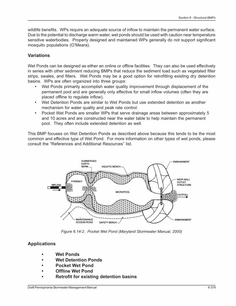
wildlife benefits. WPs require an adequate source of inflow to maintain the permanent water surface.Due to the potential to discharge warm water, wet ponds should be used with caution near temperaturesensitive waterbodies. Properly designed and maintained WPs generally do not support significantmosquito populations (O’Meara).
Variations
Wet Ponds can be designed as either an online or offline facilities. They can also be used effectivelyin series with other sediment reducing BMPs that reduce the sediment load such as vegetated filterstrips, swales, and filters. Wet Ponds may be a good option for retrofitting existing dry detentionbasins. WPs are often organized into three groups:• Wet Ponds primarily accomplish water quality improvement through displacement of the
permanent pool and are generally only effective for small inflow volumes (often they areplaced offline to regulate inflow).
• Wet Detention Ponds are similar to Wet Ponds but use extended detention as anothermechanism for water quality and peak rate control.
• Pocket Wet Ponds are smaller WPs that serve drainage areas between approximately 5and 10 acres and are constructed near the water table to help maintain the permanentpool. They often include extended detention as well.
This BMP focuses on Wet Detention Ponds as described above because this tends to be the mostcommon and effective type of Wet Pond. For more information on other types of wet ponds, pleaseconsult the “References and Additional Resources” list.
Applications
• Wet Ponds• Wet Detention Ponds• Pocket Wet Pond• Offline Wet Pond• Retrofit for existing detention basins
Figure 6.14-2. Pocket Wet Pond (Maryland Stormwater Manual, 2000)

6-380 Draft Pennsylvania Stormwater Management Manual
Section 6 - Structural BMPs
Design Considerations
1. HYDROLOGY. Wet Ponds must be able to receive and retain enough flow from rain,runoff, and groundwater to ensure long-term viability. A permanent water surface in thedeeper areas of the WP should be maintained during all but the driest periods. A relativelystable permanent water surface elevation will reduce the stress on vegetation in anadjacent to the pond. A WP should have a drainage area of at least 10 acres (5 acres forPocket Wet Ponds) or some means of sustaining constant inflow. Even with a largedrainage area, a constant source of inflow can improve the biological health andeffectiveness of a Wet Pond while discouraging mosquito growth. Pennsylvania’sprecipitation is generally well distributed throughout the year and is therefore suited forWPs.
2. UNDERLYING SOILS. Underlying soils must be identified and tested. Generallyhydrologic soil groups “C” and “D” are suitable without modification, “A” and “B” soils mayrequire modification to reduce permeability. Soil permeability must be tested in theproposed Wet Pond location to ensure that excessive infiltration will not cause the WP todry out.
3. PLANTING SOIL. Organic soils should be used for shallow areas within Wet Ponds.Organic soils can serve as a sink for pollutants and generally have high water holdingcapacities. They will also facilitate plant growth and propagation and may hinder invasionof undesirable species.
4. SIZE AND VOLUME. The area required for a WP is generally 1 to 3 percent of its drainagearea. WPs should be sized to treat the water quality volume and, if necessary, to mitigatethe peak rates for larger events.
5. VEGETATION. Vegetation is an integral part of a Wet Pond system. Vegetation in andadjacent to a pond may enhance pollutant removal, reduce algal growth, limit erosion,improve aesthetics, create habitat, and reduce water warming (Mallin et al., 2002; NJ DEP,
Figure 6.14-3. Wet Pond at Delaware County Community College

Draft Pennsylvania Stormwater Management Manual 6-381
Section 6 - Structural BMPs
2004; University of Wisconsin, 2000). Wet Ponds should have varying depths toencourage vegetation in shallow areas. The emergent vegetation zone (areas not morethan 18" deep) generally supports the majority of aquatic vegetation and should include thepond perimeter. Robust, non-invasive, perennial plants that establish quickly are ideal forWPs. The designer should select species that are tolerant of a range of depths, inundationperiods, etc. Monoculture planting must be avoided due to the risk from pests and disease.See local sources for recommended plant lists.
6. CONFIGURATION.a. General. Wet Ponds should be designed with a length to width ratio of at least 2:1
wherever possible. If the length to width ratio is lower, the flow pathway through theWP should be maximized. A wedge-shaped pond with the major inflows on thenarrow end can prevent short-circuiting and stagnation. WPs should not beconstructed within 10 feet of the property line or within 50 feet of a private well orseptic system. Slopes in and around Wet Ponds should be 4:1 to 5:1(horizontal:vertical) or flatter whenever possible (10:1 max. for safety/aquaticbenches, see 6.d. below). Wet Ponds should have an average depth of 3 to 6 feetand a maximum depth of 8 feet. This should be shallow enough to minimizethermal stratification and short-circuiting and deep enough to prevent sedimentresuspension, reduce algal blooms, and maintain aerobic conditions.
b. Forebay/Inflows. Wet Ponds should have a forebay at all major inflow points tocapture coarse sediment, prevent excessive sediment accumulation in theremainder of the WP, and minimize erosion by inflow. The forebays should contain10 to 15 percent of the total permanent pool volume and should be 4 to 6 feet deep.They should be physically separated from the rest of the pond by a berm, gabionwall, etc. Flows exiting the forebay must be non-erosive to the newly constructedWP. Vegetation within forebays can increase sedimentation and reduceresuspension/erosion. The forebay bottom can be constructed of hardenedmaterials to facilitate sediment removal. Forebays should be installed withpermanent vertical markers that indicate sediment depth. Inflow channels shouldbe fully stabilized. Inflow pipes can discharge to the surface or be partiallysubmerged. WPs must be protected from the erosive force of the inflow.
c. Outlet. Outlet control devices should draw from open water areas 5 to 7 feet deepto prevent clogging and allow the WP to be drained for maintenance. Outletdevices are generally multistage structures with pipes, orifices, or weirs for flowcontrol. A reverse slope pipe terminating 2 to 3 feet below the normal watersurface, minimizes the discharge of warm surface water and is less susceptible toclogging by floating debris. Orifices, if used, should be at least 2.5 inches indiameter and should be protected from clogging. Outlet devices should be installedin the embankment for accessibility. If possible, outlet devices should enable thenormal water surface to be varied. This allows the water level to be adjusted (ifnecessary) seasonally, as the WP accumulates sediment over time, if desiredgrades are not achieved, or for mosquito control. A pond drain should also beincluded which allows the permanent pool to be completely drained for maintenancewithin 24 hours. The outlet pipe should generally be fitted with an anti-seep collarthrough the embankment. Online facilities should have an emergency spillway thatcan safely pass the 100-year storm with 1 foot of freeboard. All outflows should beconveyed downstream in a safe and stable manner.

6-382 Draft Pennsylvania Stormwater Management Manual
Section 6 - Structural BMPs
d. Safety/Aquatic Benches. All areas that are deeper than 4 feet should have twosafety benches, totaling 15 feet in width. One should start at the normal watersurface and extend up to the pond side slopes at a maximum slope of 10 percent.The other should extend from the water surface into the pond to a maximum depthof 18 inches, also at slopes no greater than 10 percent.
7. WET POND BUFFER. To enhance habitat value, visual aesthetics, water temperature, andpond health, a 25-foot buffer should be added from the maximum water surface elevation.The buffer should be planted with trees, shrubs, and native ground covers. Accept inmaintenance access areas, turf grass should not be used. Existing trees within the buffershould be preserved. If soils in the buffer will become compacted during construction, soilrestoration should take place to aid buffer vegetation.
8. MAINTENANCE ACCESS. Permanent access must be provided to the forebay, outlet, andembankment areas. It should be at least 9 feet wide, have a maximum slope of 15%, andbe stabilized for vehicles.
9. PLAN ELEMENTS. The plans detailing the Wet Ponds should clearly show the WPconfiguration, inlets and outlets, elevations and grades, safety/aquatic benches, and thelocation, quantity, and propagation methods of pond/buffer vegetation. Plans should alsoinclude site preparation techniques, construction sequence, as well as maintenanceschedules and requirements.
10. REGULATION. Wet Ponds that have drainage areas over 100 acres, embankmentsgreater than 15 feet high, or a capacity greater than 50 acre-feet may be regulated as adam by PADEP (see Title 25, Chapter 105 of the Pennsylvania Code). Once established,portions of WPs may be regulated as Wetlands.
Figure 6.14-4. Wet Pond at Applebrook Golf Course, East Goshen Township, Chester County, PA
Draft Pennsylvania Stormwater Management Manual 6-383
Section 6 - Structural BMPs
Detailed Stormwater Functions
Volume Reduction Calculations
Although not typically considered a volume-reducing BMP, Wet Ponds can achieve some volumereduction through infiltration and evapotranspiration, especially during small storms. According tothe International Stormwater BMP Database, wet ponds have an average annual volume reductionof 7 percent (Strecker et al., 2004). Hydrologic calculations that should be performed to verify thatthe WP will have a viable amount of inflow can also predict the water surface elevation under varyingconditions. The volume stored between the predicted water level and the lowest outlet elevation willbe removed from the storm that occurs under those conditions.
Peak Rate Mitigation Calculations
Peak rate is primarily controlled in Wet Ponds through the transient storage above the normal watersurface. See Section 9 for Peak Rate Mitigation methodology.
Water Quality Improvement
Wet Ponds improve runoff quality through settling, filtration, uptake, chemical and biologicaldecomposition, volatilization, and adsorption. WPs are relatively effective at removing many commonstormwater pollutants including suspended solids, heavy metals, total phosphorus, total nitrogen,and pathogens. The pollutant removal effectiveness varies by season and may be affected by theage of the WP. It has been suggested that this type of BMP does not provide significant nutrientremoval in the long term unless vegetation is harvested because captured nutrients are releasedback into the water by decaying plant material. Even if this is true, nutrients are usually releasedgradually and during the non-growing season when downstream susceptibility is generally low(Hammer, 1990). See Section 9 for Water Quality Improvement methodology which addresses pollutantremoval effectiveness of this BMP.
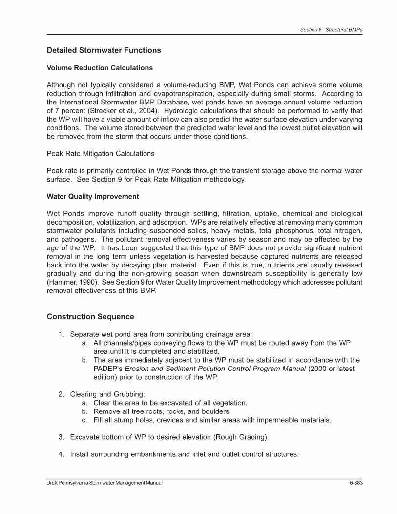
Construction Sequence
1. Separate wet pond area from contributing drainage area:a. All channels/pipes conveying flows to the WP must be routed away from the WP
area until it is completed and stabilized.b. The area immediately adjacent to the WP must be stabilized in accordance with the
PADEP’s Erosion and Sediment Pollution Control Program Manual (2000 or latestedition) prior to construction of the WP.
2. Clearing and Grubbing:a. Clear the area to be excavated of all vegetation.b. Remove all tree roots, rocks, and boulders.c. Fill all stump holes, crevices and similar areas with impermeable materials.
3. Excavate bottom of WP to desired elevation (Rough Grading).
4. Install surrounding embankments and inlet and outlet control structures.

6-384 Draft Pennsylvania Stormwater Management Manual
Section 6 - Structural BMPs
5. Grade and prepare subsoil.
6. Apply and grade planting soil.a. Matching design grades is crucial because aquatic plants can be very sensitive to
depth.
7. Apply erosion-control measures, if applicable.
8. Seed, plant and mulch according to Planting Plan
9. Install any anti-grazing measures, if necessary.
10. Follow required maintenance and monitoring guidelines.
Maintenance Issues
Wet Ponds must have a maintenance plan and privately owned facilities should have an easement,deed restriction, or other legal measure to prevent neglect or removal. During the first growingseason or until established, vegetation should be inspected every 2 to 3 weeks. WPs should beinspected at least 4 times per year and after major storms (greater than 2 inches in 24 hours) or rapidice breakup. Inspections should access the vegetation, erosion, flow channelization, bank stability,inlet/outlet conditions, embankment, and sediment/debris accumulation. The pond drain should alsobe inspected and tested 4 times per year. Problems should be corrected as soon as possible. WetPond and buffer vegetation may require support – watering, weeding, mulching, replanting, etc. –during the first 3 years. Undesirable species should be carefully removed and desirable replacementsplanted if necessary.
Once established, properly designed and installed Wet Ponds should require little maintenance.Vegetation should maintain at least an 85 percent cover of the emergent vegetation zone and bufferarea. Annual harvesting of vegetation may increase the nutrient removal of WPs; if performed itshould generally be done in the summer so that there is adequate regrowth before winter. Careshould be taken to minimize disturbance, especially of bottom sediments, during harvesting. Thepotential disturbance from harvesting may outweigh its benefits unless the WP receives a particularlyhigh nutrient load or discharges to a nutrient sensitive waterbody. Sediment should be removed fromthe forebay before it occupies 50 percent of the forebay, typically every 5 to 10 years.
Cost Issues
The construction cost of Wet Ponds can vary greatly depending on the configuration, location, site-specific conditions, etc. Typical construction costs in 2004 dollars range from approximately $25,000to $50,000 per acre-foot of storage (based on USEPA, 1999). Costs are generally most dependenton the amount of earthwork and the planting. Annual maintenance costs have been reported to beapproximately 3 to 5 percent of the capital costs although there is little data available to support this.

Draft Pennsylvania Stormwater Management Manual 6-385
Section 6 - Structural BMPs
Specifications:
The following specifications are provided for information purposes only. These specifications includeinformation on acceptable materials for typical applications, but are by no means exclusive or limiting.The designer is responsible for developing detailed specifications for individual design projects inaccordance with the project conditions.
1. Excavationa. The area to be used for the WP should be excavated to the required depth below
the desired bottom elevation to accommodate any required impermeable liner,organic matter, and/or planting soil.
b. The compaction of the subgrade and/or the installation of any impermeable linerswill follow immediately.
2. Subsoil Preparationa. Subsoil shall be free from hard clods, stiff clay, hardpan, ashes, slag, construction
debris, petroleum hydrocarbons, or other undesirable material. Subsoil must not bedelivered in a frozen or muddy state.
b. Scarify the subsoil to a depth of 8 to 10 inches with a disk, rototiller, or similarequipment.
c. Roll the subsoil under optimum moisture conditions to a dense seal layer with fourto six passes of a sheepsfoot roller or equivalent. The compacted seal layer shallbe at least 8 inches thick.
3. Planting Soil (Topsoil)a. See Appendix C for Planting Soil requirements.b. Use a minimum of 12 inches of topsoil in the emergent vegetation zone (less than
18" deep) of the pond. If natural topsoil from the site is to be used it must have atleast 8 percent organic carbon content (by weight) in the A-horizon for sandy soilsand 12% for other soil types.
c. If planting soil is being imported it should be made up of equivalent proportions oforganic and mineral materials.
d. Lime should not be added to planting soil unless absolutely necessary as it mayencourage the propagation of invasive species.
e. The final elevations and hydrology of the vegetative zones should be evaluatedprior to planting to determine if grading or planting changes are required.
4. Vegetationa. Plant Lists for WPs can be found locally. No substitutions of specified plants will be
accepted without prior approval of the designer. Planting locations shall be basedon the Planting Plan and directed in the field by a qualified wetland ecologist.
b. All Wet Pond plant stock shall exhibit live buds or shoots. All plant stock shall beturgid, firm, and resilient. Internodes of rhizomes may be flexible and notnecessarily rigid. Soft or mushy stock shall be rejected. The stock shall be free ofdeleterious insect infestation, disease and defects such as knots, sun-scald,injuries, abrasions, or disfigurement that could adversely affect the survival orperformance of the plants.
c. All stock shall be free from invasive or nuisance plants or seeds.d. During all phases of the work, including transport and onsite handling, the plant
materials shall be carefully handled and packed to prevent injuries and desiccation.During transit and onsite handling, the plant material shall be kept from freezing andshall be kept covered, moist, cool, out of the weather, and out of the wind and sun.

6-386 Draft Pennsylvania Stormwater Management Manual
Section 6 - Structural BMPs
Plants shall be watered to maintain moist soil and/or plant conditions until accepted.e. Plants not meeting these specifications or damaged during handling, loading, and
unloading will be rejected.f. Detailed planting specifications can be found locally, and in Appendix B.
5. Outlet Control Structurea. Outlet control structures shall be constructed of non-corrodible material.b. Outlets shall be resistant to clogging by debris, sediment, floatables, plant material,
or ice.c. Materials shall comply with applicable specifications (PennDOT or AASHTO, latest
edition)
Draft Pennsylvania Stormwater Management Manual 6-387
Section 6 - Structural BMPs
References
Auckland Regional Council. Stormwater Management Devices: Design Guidelines Manual. Auckland,New Zealand: 2003.
Caraco, D. and Claytor, R. Stormwater BMP Design Supplement for Cold Climates. 1997.
Center for Watershed Protection and Maryland Department of the Environment. 2000 MarylandStormwater Design Manual. Baltimore, MD: 2000.
Center for Watershed Protection for NYS Department of Environmental Conservation. New YorkState Stormwater Management Design Manual. October 2001.
CH2MHILL. Pennsylvania Handbook of Best Management Practices for Developing Areas. 1998.
Cummings and Booth, circa 2003. “Stormwater Pollutant Removal by Two Wet Ponds in Bellevue,Washington.” Department of Civil and Environmental Engineering, University of Washington,Seattle, WA, 23 pp.
“Effectiveness of Best Management Practices (BMPs) for Stormwater Treatment.” City of Greensboro(NC), Water Resources Department, circa 2000. Available as of October 2004 at http://www.greensboro-nc.gov/stormwater/Quality/bmpeffectiveness.htm.
Federal Highway Administration, Stormwater Best Management Practices in an Ultra-Urban Setting:Selection and Monitoring. “Fact Sheet – Detention Basins.”
Hammer, D.A. (editor). Constructed Wetlands for Wastewater Treatment, Municipal, Industrial andAgricultural. Ann Arbor, MI: Lewis Publishers, 1990.
Mallin, M.; Ensign, S.; Wheeler, T.; and Mayes; D. “Pollutant Removal Efficacy of Three Wet DetentionPonds.” Journal of Environmental Quality 31: 654-660 (2002).
New Jersey Department of Environmental Protection. New Jersey Stormwater Best ManagementPractices Manual. 2004.
O’Meara, G.F. “Mosquito Associated with Stormwater Detention/Retention Areas.” University ofFlorida, Institute of Food and Agricultural Sciences.
Strecker, E.W.; Quigley, M.M.; Urbonas, B.; and Jones, J. “Analyses of the Expanded EPA/ASCEInternational BMP Database and Potential Implications for BMP Design.” Proceedings of theWorld Water and Environmental Resources Congress 2004, Salt Lake City, Utah.
United States Environmental Protection Agency (USEPA). Storm Water Technology Fact Sheet: WetDetention Ponds (EPA 832-F-99-048) 1999.

6-388 Draft Pennsylvania Stormwater Management Manual
Section 6 - Structural BMPs

Draft Pennsylvania Stormwater Management Manual 6-389
Section 6 - Structural BMPs
Runoff Quality/Peak Rate BMPsBMP 6.15: Dry Extended Detention Basin
A dry extended detention basin is an earthen structure,constructed either by impoundment of a naturaldepression or excavation of existing soil, that providestemporary storage of runoff and functions hydraulicallyto attenuate stormwater runoff peaks. The drydetention basin, as constructed in countless locationssince the mid-1970’s and representing the primaryBMP measure until now, has served to control the peakrate of runoff, although some water quality benefitaccrued by settlement of the larger particulate fractionof suspended solids. This extended version is intendedto enhance this mechanism in order to maximize waterquality benefits.
The basin outlet structure must be designed to detain runoff from the stormwater quality designstorm for extended periods. Some volume reduction is also achieved by a dry basin throughinitial saturation of the soil mantle, even when compacted, and some evaporation takes placeduring detention. The net volume reduction for design storms is minimal, especially if the precedentsoil moisture is assumed as in other volume reduction BMPs.
Pollutant Removal60%40%20%
TSS:TP:
NO3:
Stormwater FunctionsLowLowHighMedium
Volume Reduction:Recharge:
Peak Rate Control:Water Quality:
Potential ApplicationsResidential:
Commercial:Ultra Urban:
Industrial:Retrofit:
Highway/Road:
YESYESLIMITED*YESLIMITEDYES
Key Design Elements• Extended detention basins shall have a minimum
contributing area of 10 acres or more (25 or more arerecommended).
• Detention basins are typically designed to control runoffpeak rates for rainfall events with return frequencies of 2years, 5 years, 10 years and 25 years. Some localordinances may require control of less frequent storms,such as the 50 and 100-year storms.
• A forebay and micropool should be incorporated into thedesign in order to maximize water quality control, throughincreased sedimentation and extended detention/retention of runoff volume from the water quality designstorm.
• Low flow channels are not recommended except wheresevere ponding is anticipated due to in situ soilconditions.
• Compaction of the basin bottom should be avoided. Inthe event that compaction should occur, soils shall berestored/amended as per BMP 4.3 – Soils Amendment.
• It is recommended that detention basin bottoms bevegetated with a variety of native species, includingtrees, woody shrubs and herbaceous plants. The use ofturf lawn is not recommended.
*May be limited by sizing constraints and theability to meet water quality standards.
6-390 Draft Pennsylvania Stormwater Management Manual
Section 6 - Structural BMPs
Description
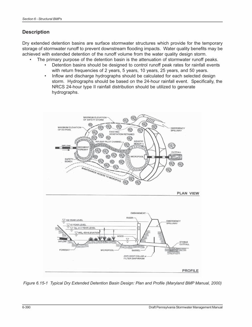
Dry extended detention basins are surface stormwater structures which provide for the temporarystorage of stormwater runoff to prevent downstream flooding impacts. Water quality benefits may beachieved with extended detention of the runoff volume from the water quality design storm.
• The primary purpose of the detention basin is the attenuation of stormwater runoff peaks.• Detention basins should be designed to control runoff peak rates for rainfall events
with return frequencies of 2 years, 5 years, 10 years, 25 years, and 50 years.• Inflow and discharge hydrographs should be calculated for each selected design
storm. Hydrographs should be based on the 24-hour rainfall event. Specifically, theNRCS 24-hour type II rainfall distribution should be utilized to generatehydrographs.
Figure 6.15-1 Typical Dry Extended Detention Basin Design: Plan and Profile (Maryland BMP Manual, 2000)

Draft Pennsylvania Stormwater Management Manual 6-391
Section 6 - Structural BMPs
• Basins shall be designed to provide water quality treatment storage to capture thecomputed runoff volume of the water quality design storm.• Detention basins shall have a sediment forebay or equivalent upstream
pretreatment. The forebay shall consist of a separate cell, formed by an acceptablebarrier and will require periodic sediment removal.
• A micropool storage area shall be designed where feasible for the extendeddetention of runoff volume from the water quality design storm.
• Flow paths from inflow points to outlets shall be maximized.
Variations
Sub-surface extended detention
Extended detention storage can also be provided in a variety of sub-surface structural elements,such as underground vaults, tanks, large pipes or other structural media placed in an aggregate filledbed in the soil mantle. All such systems are designed to provide runoff peak rate mitigation as theirprimary function, but some pollutant removal may be included. Regular maintenance is required,since the structure must be drained within a design period and cleaned to assure detention capacityfor subsequent rainfall events. These facilities are usually intended for space-limited applicationsand are not intended to provide significant water quality treatment.
• Underground vaults are typically box shaped underground stormwater storage facilitiesconstructed of reinforced concrete, while tanks are usually constructed of large diametermetal or plastic pipe. They may be situated within a building, but the use of internal spaceis frequently not cost beneficial.• Storage design and routing methods are the same as for surface detention basins.• Underground vaults and tanks do not provide water quality treatment and must be
used in combination with a pretreatment BMP.
• Underground detention beds can be constructed by excavating a subsurface area andfilling with uniformly graded aggregate for support of overlying land uses.• This approach may be used where space is limited but subsurface infiltration is not
feasible due to high water table conditions or shallow soil mantle.• As with detention vaults and tanks, this facility provides minimal water quality
treatment and must be used in combination with a pretreatment BMP.• It is recommended that underground detention facilities not be lined to allow for
even minimal infiltration, except in the case where toxic contamination is possible.
Applications
• Low Density Residential Development
• Industrial Development
• Commercial Development
• Urban Areas

6-392 Draft Pennsylvania Stormwater Management Manual
Section 6 - Structural BMPs
Design Considerations
1. Storage Volume, Depth and Duration
a. Extended detention basins are usually designed to mitigate runoff peak rates for the2-year, 5-year, 10-year, 25-year, and 50-year rainfall events.
b. An emergency outlet or spillway which is capable of conveying the spillway designflood (SDF) must be included in the design. The SDF is usually equal to the 100-year design flood
c. Extended detention basins should be designed to treat the runoff volume producedby the water quality design storm.
d. The detention time is defined as the time from when the maximum storage volumeis achieved until only 10 percent of that volume remains in the basin. In order toachieve a 60 percent total suspended solids removal rate, a 24-hour detention timeis required within an extended detention basin.
e. The lowest elevation within an extended dry detention basin shall be at least 2 feetabove the seasonal high water table. If high water table conditions are anticipated,then the design of a wet pond, constructed wetland or bioretention facility should beconsidered.
f. The maximum water depth of the basin shall not exceed 10 feet.
2. Dry Extended Detention Basin Location
a. Extended detention basins shall be located down gradient of disturbed ordeveloped areas on the site. The basin must collect as much site runoff aspossible, especially from the site’s impervious surfaces (roads, parking, buildings,etc.).
b. Extended detention basins shall not be constructed on steep slopes, nor shallslopes be significantly altered or modified to reduce the steepness of the existingslope, for the purpose of installing a basin.
c. Extended detention basins shall not worsen the runoff potential of the existing siteby removal of trees for the purpose of installing a basin.
d. Extended detention basins shall not be constructed in areas with high quality and/orwell draining soils, which are adequate for the installation of BMPs capable ofachieving stormwater infiltration.
e. Extended detention basins shall not be constructed within jurisdictional waters,including wetlands.
f. The use of extended detention basins within Exceptional Value or High Qualitywatersheds as defined by Chapter 93 of Pennsylvania’s Code is not recommendedand may be prohibited by local ordinances.
3. Basin Sizing and Configuration
a. Basins should be shaped to maximize the length of stormwater flow pathways andminimize short-circuited inlet-outlet systems. Basins shall have a minimum width of10 feet. A minimum length-to-width ratio of 2:1 is recommended to maximizesedimentation.
b. Irregularly shaped basins are encouraged and appear more natural, or less“engineered”.

Draft Pennsylvania Stormwater Management Manual 6-393
Section 6 - Structural BMPs
c. If site conditions inhibit construction of a long, narrow basin, baffles constructedfrom earthen berms or other materials can be incorporated into the pond design to“lengthen” the stormwater flow path.
d. Low flow channels shall not be incorporated in the design, except where there is aconcern for severe ponding due to in situ soils. In this case, low flow channels shallalways be vegetated with a maximum slope of 3 percent to encouragesedimentation. Alternatively, other BMPs may be considered such as wet ponds,constructed wetlands or bioretention.
4. Embankments
a. Vegetated embankments less than or equal to 3 feet in height are recommended,however embankments must be less than 15 feet in height and shall have sideslopes no steeper than 3:1 (horizontal to vertical).
b. The basin shall have a minimum freeboard of 1 foot above the SDF elevation.c. Woody vegetation can be planted in the immediate embankment area, unless the
root system will compromise the structural integrity.
5. Inlet Structures
a. Inlet structures to basin shall not be submerged at the normal pool depth.b. Erosion protection measures shall be utilized to stabilize inflow structures and
channels.
6. Outlet Design
a. In order to meet designs storm requirements, dry extended detention basins willhave a multistage outlet structure. Three elements are typically included in thisdesign:
1. A low-flow outlet that controls the extended detention and functions to slowlyrelease the water quality design storm.
2. A primary outlet that functions to attenuate the peak of larger design storms.3. An emergency overflow outlet/spillway
b. The primary outlet structure should incorporate weirs, orifices, pipes or acombination of these to control runoff peak rates for required design storms. Waterquality storage shall be provided below the invert of the primary outlet. Whenrouting basins, the low-flow outlet should be included in the depth-dischargerelationship.
c. Energy dissipaters are to be placed at the end of the primary outlet to preventerosion. If the basin discharges to a channel with dry weather flow, care shall betaken to minimize tree clearing along the downstream channel, and to reestablish aforested riparian zone between the outlet and natural channel. Where feasible, amultiple orifice outlet system is preferred to a single pipe.
d. The low-flow orifice shall typically be no smaller than 2.5 inches in diameter.However, the orifice diameter may be reduced to 1 inch if adequate protection fromclogging is provided.
e. The hydraulic design of all outlet structures must consider any significant tailwatereffects of downstream waterways.
f. The primary and low flow outlet shall be protected from clogging by an externaltrash rack.

6-394 Draft Pennsylvania Stormwater Management Manual
Section 6 - Structural BMPs
7. Sediment Forebay
a. Forebays shall be incorporated into the extended detention design. The forebaystorage volume is included for the water quality volume requirement.
b. Forebays shall be vegetated to improve filtering of runoff, to reduce runoff velocity,and to stabilize soils against erosion. Forebays are typically constructed as shallowmarsh areas and should adhere to the following design criteria:
1. It is recommended that forebays have a minimum length of 10 feet.2. Storage shall be provided to trap sediment over a period of 2 to 10 years.
8. Vegetation and Soils Protectiona. Care shall be taken to prevent compaction of in situ soils in the bottom of the
extended detention basin in order to promote healthy plant growth and toencourage infiltration. If soils compaction is not prevented during construction, soilsshall be restored as discussed in BMP 6.19 – Soils Amendment & Restoration.
b. It is recommended that basin bottoms be vegetated in a diverse native planting mixto reduce maintenance needs, promote natural landscapes, and increase infiltrationpotential. Vegetation may include trees, woody shrubs and meadow/wetlandherbaceous plants.
c. Woody vegetation can be planted on the embankments or within 25 feet of theemergency overflow spillway, unless the root system will compromise the structuralembankment.
d. Meadow grasses or other deeply rooted herbaceous vegetation is recommended onthe interior slope of embankments.
e. Fertilizers and pesticides shall not be used.
9. Special Design Considerationsa. Ponds that have embankments higher than 15 feet or will impound more that 50
acre-feet of runoff during the high-water condition will be regulated as dams by
Figure 6.15-2 Picture of a sediment forebay created with a riprap berm. Although not shown, it isrecommended that sediment forebays be vegetated with a minimum of native wet meadow planting, however
more substantial plantings are preferred. (Chester County Conservation District photo, 2002)

Draft Pennsylvania Stormwater Management Manual 6-395
Section 6 - Structural BMPs
PADEP. The designer shall consult Pennsylvania Chapter 105 to determine whichprovisions may apply to the specific project in question.
b. Extended detention ponds shall never be utilized as recreation areas due to healthand safety issues. Design features that discourage access are recommended.
Detailed Stormwater Functions
Peak Rate Mitigation
Inflow and discharge hydrographs must be calculated for each design storm. Hydrographs shouldbe based on a 24-hour rainfall event. The Natural Resources Conservation Service’s (NRCS) 24-hour Type II rainfall distribution should be utilized.
The predevelopment and post-development hydrographs for the drainage area shall be calculatedusing the NRCS’s methodology described in the NRCS National Engineering Handbook. TheNRCS’s method uses a non-dimensional unit hydrograph and the soil cover complex method topredict runoff peak rates. Once the hydrograph has been computed, it can be routed manually orwith a computer-modeling program.
Water Quality Improvement
Water quality mitigation is partially achieved by retaining the runoff volume from the water qualitydesign storm for a minimum of 24 hours. The low flow orifice shall be sized to detain thecalculated water quality runoff volume for at least 24 hours. Sediment forebays should beincorporated into the design to improve sediment removal. The storage volume of the forebaymay be included in the calculated storage of the water quality design volume.
Construction Sequence
1. Install all temporary erosion and sedimentation controls.a. The area immediately adjacent to the basin must be stabilized in accordance with
the PADEP’s Erosion and Sediment Pollution Control Program Manual (2000 orlatest edition) prior to basin construction.
2. Prepare site for excavation and/or embankment construction.a. All existing vegetation should remain if feasible and shall only be removed if
necessary for construction.b. Care should be taken to prevent compaction of the basin bottom.c. If excavation is required, clear the area to be excavated of all vegetation. Remove
all tree roots, rocks, and boulders only in excavation area3. Excavate bottom of basin to desired elevation (if necessary).4. Install surrounding embankments and inlet and outlet control structures.5. Grade subsoil in bottom of basin, taking care to prevent compaction. Compact surrounding
embankment areas and around inlet and outlet structures.6. Apply and grade planting soil.7. Apply geo-textiles and other erosion-control measures.8. Seed, plant and mulch according to Planting Plan9. Install any anti-grazing measures, if necessary.

6-396 Draft Pennsylvania Stormwater Management Manual
Section 6 - Structural BMPs
Maintenance Issues
Maintenance is necessary to ensure proper functionality of the extended detention basin and shouldtake place periodically on an annual basis. A basin maintenance plan should be developed whichincludes the following measures:• All basin structures expected to receive and/or trap debris and sediment must be inspected
for clogging and excessive debris and sediment accumulation at least four times per year,as well as after every storm greater than 1 inch.• Structures include basin bottoms, trash racks, outlets structures, riprap or gabion
structures, and inlets.• Sediment removal should be conducted when the basin is completely dry. Sediment
should be disposed of properly and once sediment is removed, disturbed areas need to beimmediately stabilized and revegetated.
• Mowing and/or trimming of vegetation should be performed as necessary to sustain thesystem, but all detritus must be removed from the basin.• Vegetated areas should be inspected annually for erosion.• Vegetated areas should be inspected annually for unwanted growth of exotic/
invasive species.• Vegetative cover should be maintained at a minimum of 95 percent. If vegetative
cover has been reduced by 10%, vegetation should be reestablished.
Cost Issues
The construction costs associated with dry extended detention basins can range considerably. Onerecent study evaluated the cost of all pond systems (Brown and Schueler, 1997). Adjusting forinflation, the cost of dry extended detention ponds can be estimated with the equation:
C = 12.4V0.760
Where:
C = Construction, Design and Permitting CostV = Volume needed to control the 10-year storm (cubic feet)Using this equation, a typical construction costs are:$ 41,600 for a 1 acre-foot pond$ 239,000 for a 10 acre-foot pond$ 1,380,000 for a 100 acre-foot pond
Dry extended detention basins utilizing highly structural design features (rip-rap for erosion control,etc.) are more costly than naturalized basins. There is an installation cost savings associated with anatural vegetated slope treatment which is magnified by the additional environmental benefits provided.Long-term maintenance costs are reduced when more naturalized approaches are utilized due to theability of native vegetation to adapt to local weather conditions and a reduced need for maintenance,such as mowing and fertilization.
Normal maintenance costs can be expected to range form 3 to 5 percent of the construction costs onan annual basis.

Draft Pennsylvania Stormwater Management Manual 6-397
Section 6 - Structural BMPs
Specifications
The following specifications are provided for information purposes only. These specifications includeinformation on acceptable materials for typical applications, but are by no means exclusive or limiting.The designer is responsible for developing detailed specifications for individual design projects inaccordance with the project conditions.
1. Site Preparationa. All excavation areas, embankments, and where structures are to be installed shall
be cleared and grubbed as necessary, but trees and existing vegetation shall beretained and incorporated within the dry detention basin area where necessary.Under no circumstances shall trees be removed.
b. Where feasible, trees and other native vegetation shall be protected, even in areaswhere temporary inundation is expected. A minimum 10-foot radius around the inletand outlet structures can be cleared to allow construction.
c. Any cleared material shall be used as mulch for erosion control or soil stabilization.d. Care shall be taken to prevent compaction of the bottom of the reservoir. If
compaction should occur, soils shall be restored and amended.
2. Earth Fill Material & Placementa. The fill material shall be taken from approved designated excavation areas. It shall
be free of roots, stumps, wood, rubbish, stones greater than 6 inches, or otherobjectionable materials. Materials on the outer surface of the embankment musthave the capability to support vegetation.
b. Areas where fill is to be placed shall be scarified prior to placement. Fill materialsfor the embankment shall be placed in maximum 8-inch lifts. The principal spillwaymust be installed concurrently with fill placement and not excavated into theembankment.
c. The movement of the hauling and spreading equipment over the site shall becontrolled. For the embankment, the entire surface of each lift shall be traversed bynot less than one tread track of heavy equipment or compaction shall be achievedby a minimum of four complete passes of a sheepsfoot, rubber tired or vibratoryroller. Fill material shall contain sufficient moisture so that if formed in to a ball it willnot crumble, yet not be so wet that water can be squeezed out.
3. Embankment Corea. The core shall be parallel to the centerline of the embankment as shown on the
plans. The top width of the core shall be at least four feet. The height shall extendup to at least the 10-year water elevation or as shown on the plans. The sideslopes shall be 1 to 1 or flatter. The core shall be compacted with constructionequipment, rollers, or hand tampers to assure maximum density and minimumpermeability. The core shall be placed concurrently with the outer shell of theembankment.
4. Structure Backfilla. Backfill adjacent to pipes and structures shall be of the type and quality conforming
to that specified for the adjoining fill material. The fill shall be placed in horizontallayers not to exceed four inches in thickness and compacted by hand tampers orother manually directed compaction equipment. The material shall fill completely allspaces under and adjacent to the pipe. At no time during the backfilling operationshall driven equipment be allowed to operate closer than four feet to any part of the

6-398 Draft Pennsylvania Stormwater Management Manual
Section 6 - Structural BMPs
structure. Equipment shall not be driven over any part of a concrete structure orpipe, unless there is a compacted fill of 24 inches or greater over the structure orpipe.
b. Structure backfill may be flowable fill meeting the requirements of the PADOTStandard Specifications for Construction. Material shall be placed so that aminimum of 6 inches of flowable fill shall be under (bedding), over and, on the sidesof the pipe. It only needs to extend up to the spring line for rigid conduits. Averageslump of the fill material shall be 7 inches to assure flowability of the mixture.Adequate measures shall be taken (sand bags, etc.) to prevent floating the pipe.When using flowable fill all metal pipe shall be bituminous coated. Adjoining soil fillshall be placed in horizontal layers not to exceed 4 inches in thickness andcompacted by hand tampers or other manually directed compaction equipment.
5. Pipe Conduitsa. Corrugated Metal Pipe – All of the following criteria shall apply for corrugated metal
pipe:i. Materials - Polymer coated steel pipe, Aluminum coated steel pipe,
Aluminum pipe –This pipe and its appurtenances shall conform to therequirements of AASTO Specifications with watertight coupling bands orflanges.
ii. Coupling bands, anti-seep collars, end sections, etc., must be composed ofthe same material and coatings as the pipe. Metals must be insulated fromdissimilar materials with use of rubber or plastic insulating materials at least24 mils in thickness.
iii. Connections – All connections with pipes must be completely watertight.The drain pipe or barrel connection to the riser shall be welded all aroundwhen the pipe and riser are metal. Anti-seep collars shall be connected tothe pipe in such a manner as to be completely watertight. Dimple bands arenot considered to be watertight.
iv. Bedding – The pipe shall be firmly and uniformly bedded throughout itsentire length. Where rock or soft, spongy or other unstable soil isencountered, all such material shall be removed and replaced with suitableearth compacted to provide adequate support.
v. Backfilling shall conform to “Structure Backfill”.vi. Other details (anti-seep collars, valves, etc.) shall be as shown on drawings.
b. Reinforced Concrete Pipe - All of the following criteria shall apply for reinforcedconcrete pipe:
i. Materials – Reinforced concrete pipe shall have bell and spigot joints withrubber gaskets and shall equal or exceed ASTM Standards.
ii. Bedding – Reinforced concrete pipe conduits shall be laid in a concretebedding/cradle for their entire length. This bedding/cradle shall consist ofhigh slump concrete placed under the pipe and up the sides of the pipe atleast 50% of its outside diameter with a minimum thickness of 6 inches.Where a concrete cradle is not needed for structural reasons, flowable fillmay be used as described in the “Structure Backfill” section of thisspecification. Gravel bedding is not permitted.
iii. Laying pipe – Bell and spigot pipe shall be placed with the bell endupstream. Joints shall be made in accordance with recommendations of themanufacturer of the material. After the joints are sealed for the entire line,

Draft Pennsylvania Stormwater Management Manual 6-399
Section 6 - Structural BMPs
the bedding shall be placed so that all spaces under the pipe are filled.Care shall be exercised to prevent any deviation from the original line andgrade of the pipe.
iv. Backfilling shall conform to “Structure Backfill”.v. Other details (anti-seep collars, valves, etc.) shall be as shown on drawings.
c. Plastic Pipei. Materials – PVC pipe shall be PVC-1120 or PVC-1220 conforming to ASTM
Standards. Corrugated High Density Polyethylene (HDPE) pipe, couplingsand fittings shall meet the requirements of AASHTO Specifications.
ii. Joints and connections to anti-seep collars shall be completely watertight.iii. Bedding – The pipe shall be firmly and uniformly bedded throughout its
entire length. Where rock or soft, spongy or other unstable soil isencountered, all such material shall be removed and replaced with suitableearth compacted to provide adequate support.
iv. Backfilling shall conform to “Structure Backfill”.v. Other details (anti-seep collars, valves, etc.) shall be as shown on drawings.
d. Drainage Diaphragms – When a drainage diaphragm is used, a registeredprofessional engineer will supervise the design and construction inspection.
6. Rock Riprapa. Rock riprap shall meet the requirements of Pennsylvania Department of
Transportation Standard Specifications.
7. Stabilizationa. All borrow areas shall be graded to provide proper drainage and left in a sightly
condition. All exposed surfaces of the embankment, spillway, spoil and borrowareas, and berms shall be stabilized by seeding, planting and mulching inaccordance with the Natural Resources Conservation Service Standards andSpecifications or as shown on the accompanying drawings.
8. Operation and Maintenancea. An operation and maintenance plan in accordance with Local or State Regulations
will be prepared for all basins. As a minimum, a dam and inspection checklist shallbe included as part of the operation and maintenance plan and performed at leastannually.

6-400 Draft Pennsylvania Stormwater Management Manual
Section 6 - Structural BMPs
References
AMEC Earth and Environmental Center for Watershed Protection et al. Georgia StormwaterManagement Manual. 2001.
Brown, W. and T. Schueler. 1997. The Economics of Stormwater BMPs in the Mid-Atlantic Region.Prepared for: Chesapeake Research Consortium. Edgewater, MD. Center for WatershedProtection. Ellicott City, MD.
California Stormwater Quality Association. California Stormwater Best Management PracticesHandbook: New Development and Redevelopment. 2003.
CH2MHILL. Pennsylvania Handbook of Best Management Practices for Developing Areas. 1998.
Chester County Conservation District. Chester County Stormwater BMP Tour Guide-PermanentSediment Forebay, 2002.
Commonwealth of PA, Department of Transportation. Pub 408 - Specifications. 1990. Harrisburg,PA.
Maryland Department of the Environment. Maryland Stormwater Design Manual. 2000.
Milner, George R. 2001. Conventional vs. Naturalized Detention Basins: A Cost/Benefit Analysis.Prepared for: The Illinois Association for Floodplain and Stormwater Management. Park Forest,IL
New Jersey Department of Environmental Protection. New Jersey Stormwater Best ManagementPractices Manual. 2004.
Stormwater Management Fact Sheet: Dry Extended Detention Pond – www.stormwatercenter.net
Vermont Agency of Natural Resources. The Vermont Stormwater Management Manual. 2002.
Washington State Department of Ecology. Stormwater Management Manual for Eastern Washington(Draft). Olympia, WA: 2002.
Draft Pennsylvania Stormwater Management Manual 6-401
Section 6 - Structural BMPs
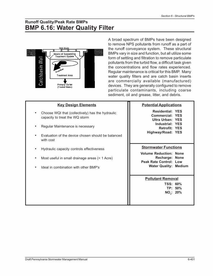
Runoff Quality/Peak Rate BMPsBMP 6.16: Water Quality Filter
A broad spectrum of BMPs have been designedto remove NPS pollutants from runoff as a part ofthe runoff conveyance system. These structuralBMPs vary in size and function, but all utilize someform of settling and filtration to remove particulatepollutants from the turbid flow, a difficult task giventhe concentrations and flow rates experienced.Regular maintenance is critical for this BMP. Manywater quality filters and are catch basin insertsare commercially available (manufactured)devices. They are generally configured to removeparticulate contaminants, including coarsesediment, oil and grease, litter, and debris.
Pollutant Removal60%50%20%
TSS:TP:
NO3:
Stormwater FunctionsNoneNoneLowMedium
Volume Reduction:Recharge:
Peak Rate Control:Water Quality:
Potential ApplicationsResidential:
Commercial:Ultra Urban:
Industrial:Retrofit:
Highway/Road:
YESYESYESYESYESYES
Key Design Elements
• Choose WQI that (collectively) has the hydrauliccapacity to treat the WQ storm
• Regular Maintenance is necessary
• Evaluation of the device chosen should be balancedwith cost
• Hydraulic capacity controls effectiveness
• Most useful in small drainage areas (< 1 Acre)
• Ideal in combination with other BMP's
6-402 Draft Pennsylvania Stormwater Management Manual
Section 6 - Structural BMPs
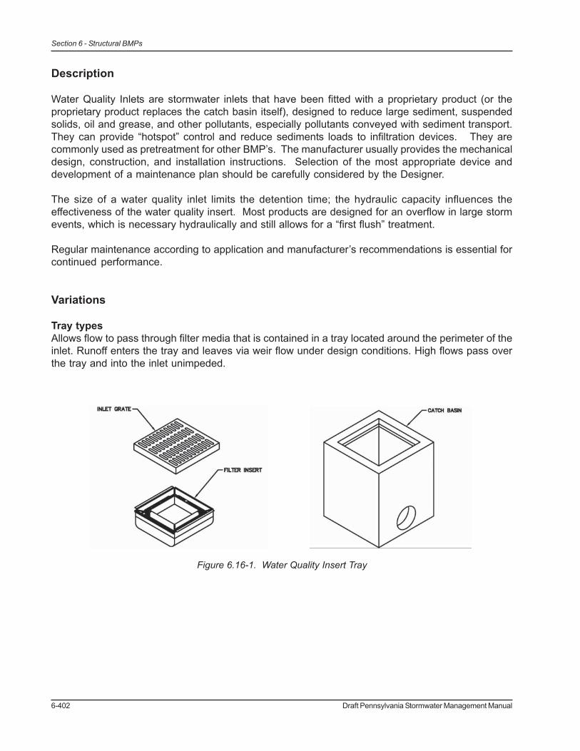
Figure 6.16-1. Water Quality Insert Tray
Description
Water Quality Inlets are stormwater inlets that have been fitted with a proprietary product (or theproprietary product replaces the catch basin itself), designed to reduce large sediment, suspendedsolids, oil and grease, and other pollutants, especially pollutants conveyed with sediment transport.They can provide “hotspot” control and reduce sediments loads to infiltration devices. They arecommonly used as pretreatment for other BMP’s. The manufacturer usually provides the mechanicaldesign, construction, and installation instructions. Selection of the most appropriate device anddevelopment of a maintenance plan should be carefully considered by the Designer.
The size of a water quality inlet limits the detention time; the hydraulic capacity influences theeffectiveness of the water quality insert. Most products are designed for an overflow in large stormevents, which is necessary hydraulically and still allows for a “first flush” treatment.
Regular maintenance according to application and manufacturer’s recommendations is essential forcontinued performance.
Variations
Tray typesAllows flow to pass through filter media that is contained in a tray located around the perimeter of theinlet. Runoff enters the tray and leaves via weir flow under design conditions. High flows pass overthe tray and into the inlet unimpeded.

Draft Pennsylvania Stormwater Management Manual 6-403
Section 6 - Structural BMPs
Bag typesInsert is made of fabric and is placed in the drain inlet around the perimeter of the grate. Runoffpasses through the bag before discharging into the drain outlet pipe. Overflow holes are usuallyprovided to pass larger flows without causing a backwater at the grate. Certain manufactured productsinclude polymers intended to increase pollutant removal effectiveness.
Baskets typesThe insert consists of “basket type” insert that sets into the inlet and has a handle to remove basketfor maintenance. Small orifices allow small storm event to weep through, larger storms overflow thebasket. Primarily useful for debris and larger sediment, and requires consistent maintenance.
Figure 6.16-2. Filter Bag Figure 6.16-3. Filter Bag Installation (FullCircle Ag, Inc., http://www.fullcircleag.com/
pages/954364/)
Figure 6.16-4. Example of a german basket-type water quality inlet, (CA, 2001).

6-404 Draft Pennsylvania Stormwater Management Manual
Section 6 - Structural BMPs
Figure 6.16-5. Sediment sump incorporated with a standard inlet.
Figures 6.16-6. Vortex separator (http://www.hydrointernational.biz/nam/ind_storm.html)
Simple, “sumps” in inletsSpace created in inlets below the invert of the pipes for sediment and debris to deposit, usuallyleaving 6-inches to 12-inches at the bottom of an inlet. Small weep holes should be drilled into thebottom of the inlet to prevent standing water for long periods of time. Regular maintenance is required.
Vortex SeparatorsThese units are not truly inserts, but separate devices designed to serve in concert with inlets andstorm sewer. A variety of products are available from different manufacturers. The primary purposeis to use centrifugal force to remove sediments and pollutants.

Draft Pennsylvania Stormwater Management Manual 6-405
Section 6 - Structural BMPs
Applications
Any existing or proposed inlet where the contributing runoff may contain significant levels of sedimentand debris, for example: parking lots, gas stations, golf courses, streets, driveways, industrial orcommercial facilities, and municipal corporation yards. Commonly used as pretreatment before otherstormwater BMPs.
Design Considerations
1. Match site considerations with manufacturer’s guidelines/specifications (i.e. land use willdetermine specific pollutants to be removed from runoff).
2. Prevent re-suspension of particles by using small drainage areas and good maintenance.
3. Retrofits should be designed to fit existing inlets.
4. Placement should be accessible to maintenance.
5. If used as part of Erosion & Sedimentation Control during construction, insert should bereconfigured (if necessary) per manufacture’s guidelines.
6. Overflow should be designed so that storms in excess of the device’s hydraulic capacitybypass the treatment and is treated by another quality BMP.
Detailed Stormwater Functions
Volume Reduction CalculationsN/A
Peak Rate Mitigation CalculationsN/A
Water Quality ImprovementIf sized to treat the WQ storm, removal rates above can be applied to that volume of water.
Construction Sequence
1. Stabilize all contributing areas before installing and connecting pipes to these inlets.
2. Follow manufacturer’s guidelines for installation. Do not use water quality inserts duringconstruction unless product is designed for it. (Some products have adsorptioncomponents that should be installed post-construction.)
Maintenance Issues
Follow the manufacturer’s guidelines for maintenance, also taking into account expected pollutantload and site conditions. Inlets should be inspected weekly during construction. Post-construction,they should be emptied when full of sediment (and trash) and cleaned at least twice a year. They

6-406 Draft Pennsylvania Stormwater Management Manual
Section 6 - Structural BMPs
Figure 6.16-7. Maintenance of a bag type water quality insert, (Full Circle Ag, Inc., http://www.fullcircleag.com/pages/954364/).
should also be inspected after significant precipitation. Maintenance is crucial to the effectiveness ofthis BMP. The more frequent a water quality insert is cleaned, the more effective it will be. One study(Pitt, 1985) found that WQI’s can store sediment up to 60% of its sump volume, and after that, theinflow resuspends the sediments into the stormwater. Some sites have found keeping a log ofsediment amount date removed helpful in planning a maintenance schedule. The EPA has a monitoringprogram, Environmental Technology Verification (ETV) Program, (www.epa.gov/etv), that may beavailable to assist with the development of a monitoring plan.
Disposal of removed material will depend on the nature of the drainage area and the intent andfunction of the water quality insert. Material removed from water quality inserts that serve “Hot Spots”such as fueling stations or that receive a large amount of debris should be handling according to DEPregulations for solid waste, such as a landfill that is approved by DEP to accept solid waste. Waterquality inserts that primary catch sediment and detritus from areas such as lawns may reuse thewaste on site, which is recommended by the DEP.
Vactor trucks may be an efficient cleaning mechanism.
Winter Concerns: There is limited data studying cold weather effects on water quality inserteffectiveness. Freezing may result in more runoff bypassing the treatment system and overflowing.Salt stratification may also reduce detention time. Colder temperatures reduce the settling velocity ofparticles, which can result in fewer particles being “trapped”. Salt and sand and significantly increasedin the winter, and may warrant more frequent maintenance, but sometimes freezing makes accessingdevices for maintenance difficult
Cost Issues
Inserts range from $400 - $10,000Pre cast range from $2000 - $3000
Specifications
See manufacturer’s instructions and specific specifications in Appendix E.

Draft Pennsylvania Stormwater Management Manual 6-407
Section 6 - Structural BMPs
References
Brzozowski, C., 2003. “Inlet Protection – Strategies for Preserving Water Quality,” Stormwatermagazine.
Lee, F. “The Right BMP’s? Another Look at Water Quality.” Stormwater magazine.
New Hampshire Watershed Management Bureau, Watershed Assistance Section, 2002. “InnovativeStormwater Treatment Technologies BMP Manual.”
Pitt, 1985.

6-408 Draft Pennsylvania Stormwater Management Manual
Section 6 - Structural BMPs

Draft Pennsylvania Stormwater Management Manual 6-409
Section 6 - Structural BMPs
6.7 Restoration BMPs

6-410 Draft Pennsylvania Stormwater Management Manual
Section 6 - Structural BMPs

Draft Pennsylvania Stormwater Management Manual 6-411
Section 6 - Structural BMPs
Restoration BMPs
BMP 6.17: Riparian Buffer Restoration
A riparian forest buffer is a permanent area oftrees and shrubs located adjacent to streams,lakes, ponds, and wetlands. Riparian forestsare the most beneficial type of buffer for theyprovide ecological and water quality benefits.Restoration of this ecologically sensitive habitatis a responsive action from past activities thatmay have eliminated any vegetation.
Pollutant Removal65%50%50%
TSS:TP:
NO3:
Stormwater FunctionsMediumMediumLow/Med.Med./High
Volume Reduction:Recharge:
Peak Rate Control:Water Quality:
Potential ApplicationsResidential:
Commercial:Ultra Urban:
Industrial:Retrofit:
Highway/Road:
YESYESYESYESYESLimited
Key Design Elements
• Reestablish buffer perennial, intermittent, andephemeral streams
• Plant native, diverse tree and shrub vegetation
• Buffer width is dependant on project preferredfunction (water quality, habitat creation, etc.)
• Minimum recommended buffer width is 35’ from topof stream bank, with 100’ preferred.
• Create a short-term maintenance and long-termmaintenance plan
• Mature forest as a vegetative target
• Clear, well-marked boundary
6-412 Draft Pennsylvania Stormwater Management Manual
Section 6 - Structural BMPs
Description
The USDA Forest Service estimates that over one-third of the rivers and streams in Pennsylvaniahave had their riparian areas degraded or altered. This fact is sobering when one considers theimportant stormwater functions that riparian buffer provides. The non-structural BMP, Riparian ForestBuffer Protection, addresses the importance of protecting the three-zone system of existing riparianbuffers.
The values of riparian buffers – economic, environmental, recreational, aesthetic, etc. – are welldocumented in scientific literature and numerous reports and thus will not be restated here in thisBMP sheet. Rather, this BMP serves to provide a starting point for the designer that seeks to restorethe riparian buffer. Important reports are cited consistently throughout this section and should bementioned upfront as sources for additional information to a designer seeking to restore a riparianbuffer. The first, the Chesapeake Bay Riparian Handbook: a Guide for Establishing and MaintainingRiparian Forest Buffers was prepared by the US Department of Agriculture (USDA) Forest Servicefor the Chesapeake Bay Program in 1997. The second, the Pennsylvania Stream ReLeaf ForestBuffer Toolkit was developed by the Alliance for the Chesapeake Bay specifically for the Pennsylvaniastreams in 1998. A third and often-referenced report, is the Riparian Forest Buffers series written byRobert Tjaden for the Maryland Cooperative Extension Service in 1998.
Riparian buffers are scientifically proven to provide a number of economic and environmental values.Buffers are characterized by high species density, high species diversity, and high bio-productivity asa transition between aquatic and upland environments. Project designer should take into accountthe benefits or services provided by the buffer and apply these to their project goals. Priorities forriparian buffer use must be established early on in the planning stages. Some important considerationswhen establishing priorities are:
• Habitat – Restoring a buffer for habitat enhancement will require a different restorationstrategy than for restoring a buffer for increased water quality.
• Stream Size – A majority of Pennsylvania’s stream miles is comprised of small streams(first, second, and third order), which may be priority areas to reduce nutrients. Establishingriparian buffers along these headwater streams will reduce the high nutrient loads relativeto flow volumes typical of small streams.
• Continuous Buffers - Establishing continuous riparian forest buffers in the landscapeshould be given a higher priority than establishing larger but fragmented buffers.Continuous buffers provide better stream shading and water quality protection, as well ascorridors for the movement of wildlife.
• Degree of Degradation – Urban streams are usually buried or piped. Streams in areaswithout forests, such as pastures, may benefit the most from buffer restoration, as sourcesof headwater streams. Highly urbanized/altered streams may not be able to provide highlevels of pollution control.
• Loading Rates - The removal of pollutants may be highest where nutrient and sedimentloading are the highest.
• Land Use – Adjacent land uses will influence Buffer Width and Vegetation types used toestablish a riparian buffer. While the three-zone riparian-forested buffers described earlierare the ideal, they may not always be feasible to establish, especially in urban situations.
Preparation of a Riparian Buffer Restoration Plan is critical to ensuring long-term success of theproject and should be completed before any planting is to occur. It is essential that site conditions

Draft Pennsylvania Stormwater Management Manual 6-413
Section 6 - Structural BMPs
are well understood, objectives of the landowner are considered, and the appropriate plants chosenfor the site, tasks that are completed in the planning stages. Below is a summary of the nine stepsthat PADEP/PADCNR advocates groups/designers/engineers/volunteers/etc., undertake during theplanning stages of a buffer restoration project.
1. Obtain Landowner Permission and SupportLandowner commitment is essential for the success of the project. Landowner must beaware of all maintenance activities that will occur once buffer is planted.
2. Make Sure Site is Suitable for RestorationIf streambanks are extensively eroded, consider alternative location. Rapidly erodingstreambanks may undermine seedlings. Streambank restoration may need to occur priorto riparian buffer restoration. Obtain professional help in evaluating need for streambankrestoration.
3. Analyze Site’s Physical ConditionsThe most important physical condition of the site is the soil, which will control plantselection. Evaluate the soil using the County soil survey book to determine important soilcharacteristics such as flooding potential, seasonal high water table, topography, soil pH,soil moisture, etc. Also, a simple field test can suffice, with direct observation of soilconditions.
4. Analyze Site’s Vegetative FeaturesExisting vegetation present at the restoration site should be examined to determine thestrategy for buffer establishment. Strategies will differ whether pre-restoration conditionsare pasture, overgrown abandoned field, mid-succession forest, or any other setting.
• Identify Desirable Species: Native tree and shrub species that thrive in riparianhabitats in Pennsylvania should be used. These species should be identified in therestoration site and protected for their seed bank potential. Several native vinesand shrubs (blackberry, greenbriar, poison ivy, Virginia creeper, and spicebush) canprovide an effective ground cover during establishment of the buffer, though shouldbe selectively controlled for herbaceous competition.
• Identify Undesirable Species: Consider utilizing undesirable species such as theblack locust for their shade function during buffer establishment. Considercontrolling invasive plants prior to buffer planting.
• Identify Sensitive Species: Since riparian zones are rich in wildlife habitat andwetland plant species to be aware of any rare, threatened or endangered plant (oranimal) species.
5. Draw a Map of the Site (Data collection)Prepare a sketch of the site that denotes important existing features, including streamwidth, length, streambank condition, adjacent land uses and stream activities, desired widthof buffer, discharge pipes, obstructions, etc.
6. Create a Design that Meets Multiple ObjectivesIdeally, the three-zone system should be incorporated into the design, in a flexible mannerto obtain water quality and landowner objectives.
6-414 Draft Pennsylvania Stormwater Management Manual
Section 6 - Structural BMPs
• Consider landowner objectives: Consider the current use of the buffer by thelandowner, especially if the buffer will be protected in perpetuity. Consider linkingthe buffer to an existing (or planned trail system).
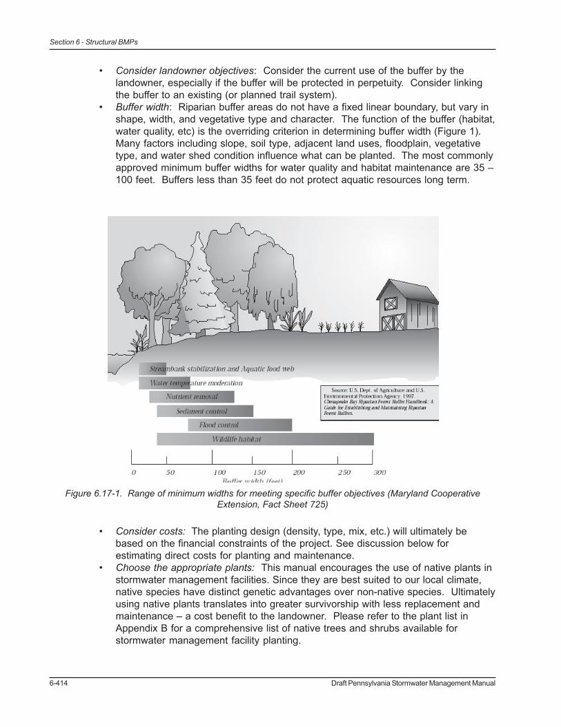
• Buffer width: Riparian buffer areas do not have a fixed linear boundary, but vary inshape, width, and vegetative type and character. The function of the buffer (habitat,water quality, etc) is the overriding criterion in determining buffer width (Figure 1).Many factors including slope, soil type, adjacent land uses, floodplain, vegetativetype, and water shed condition influence what can be planted. The most commonlyapproved minimum buffer widths for water quality and habitat maintenance are 35 –100 feet. Buffers less than 35 feet do not protect aquatic resources long term.
• Consider costs: The planting design (density, type, mix, etc.) will ultimately bebased on the financial constraints of the project. See discussion below forestimating direct costs for planting and maintenance.
• Choose the appropriate plants: This manual encourages the use of native plants instormwater management facilities. Since they are best suited to our local climate,native species have distinct genetic advantages over non-native species. Ultimatelyusing native plants translates into greater survivorship with less replacement andmaintenance – a cost benefit to the landowner. Please refer to the plant list inAppendix B for a comprehensive list of native trees and shrubs available forstormwater management facility planting.
Figure 6.17-1. Range of minimum widths for meeting specific buffer objectives (Maryland CooperativeExtension, Fact Sheet 725)

Draft Pennsylvania Stormwater Management Manual 6-415
Section 6 - Structural BMPs
Plant Size: Choice of planting stock (seeds, container seedling, bare-root seedlings, plugs, etc.)is ultimately determined by funding resources. Larger material will generally cost more, thoughwill generally establish more rapidly.
7. Draw a Planting PlanPlanting Density: Trees should be planted at a density sufficient to provide 320 trees peracres at maturity. To achieve this density, approximately 436 (10 x 10 feet spacing) to 681(8 x 8 feet spacing) trees per acre should be planted initially. Some rules of thumb for treespacing and density based on plant size at installation:
Seedlings 6-10 feet spacing (~700 seedlings / acre)Bare Root Stock 14-16 feet spacing (~200 plants / acre)Larger & Container 16 – 18 feet spacing (~150 plants/acre)
Formula for Estimating Number of Trees and Shrubs:# Plants = length x width of corridor (ft) / 50 square feet
This formula assumes each tree will occupy an average of 50 sq. ft., random placement of plantsapproximately 10 feet apart, and mortality rate of up to 40% that can be absorbed by the growingforest system.
Alternatively, Table 1 below can be utilized to estimate the number of trees per acre needed forvarious methods of spacing.
Spacing Trees Spacing Trees Spacing Trees(feet) (number) (feet) (number) (feet) (number)2x2 10,890 7x9 691 12x15 2423x3 4,840 7x10 622 12x18 2024x4 2,722 7x12 519 12x20 1824x5 2,178 7x15 415 12x25 1454x6 1,815 8x8 681 13x13 2584x7 1,556 8x9 605 13x15 2234x8 1,361 8x10 544 13x20 1684x9 1,210 8x12 454 13x25 134
4x10 1,089 8x15 363 14x14 2225x5 1,742 8x25 218 14x15 2075x6 1,452 9x9 538 14x20 1565x7 1,245 9x10 484 14x25 1245x8 1,089 9x12 403 15x15 1945x9 968 9x15 323 15x20 145
5x10 871 10x10 436 15x25 1166x6 1,210 10x12 363 16x16 1706x7 1,037 10x15 290 16x20 1366x8 908 10x18 242 16x25 1096x9 807 11x11 360 18x18 1346x10 726 11x12 330 18x20 1216x12 605 11x15 264 18x25 976x15 484 11x20 198 20x20 1097x7 889 11x25 158 20x25 877x8 778 12x12 302 25x25 70
Table 6.17-1. Number of Trees per Acre by Various Methods of Spacing (USDA Forest Service)

6-416 Draft Pennsylvania Stormwater Management Manual
Section 6 - Structural BMPs
Planting Layout: Given planting density and mix, drawing the planting plan is fairly straightforward.The plan can vary from a highly technical drawn to scale plan, or a simple line drawing of the site.Any plan must show the site with areas denoted for trees and shrub species with notes for plantspacing and buffer width.
8. Prepare Site Ahead of TimeExisting site conditions will determine the degree of preparation needed prior to planting.Invasive infestation and vegetative competition are extremely variable, and therefore mustbe considered in the planning stages. Site preparation should begin in the fall prior toplanting. Enlist professional to determine whether use of chemical controls are necessaryto prepare site for planting. Release desired existing saplings from competition byundesired species with either herbicide application (consult a professional) or physicalremoval. If utilizing a highly designed planting layout, mark site ahead of time with flags,spray paint, or other markers so that the appropriate plant is put in the right place.
9. Determine Maintenance NeedsAn effective buffer restoration project should include management and maintenanceguidelines, as well as distinctions of allowable and unallowable uses in the buffer. Bufferboundaries should be well defined with clear signs or markers. Weed control is essentialfor the survival and rapid growth of trees and shrubs, and can include any of the following:
• Organic mulch• Weed control fabrics• Shallow cultivation• Pre-emergent herbicides• Mowing
Non-chemical weed control methods are preferred since chemicals can easily enter the watersystem. If possible, avoid working in the riparian area between April 15 and August 15, themating and newborn period for local wildlife.
VariationsSee Applications
Applications• Forested Landscape
Figure 6.17-2 Recently planted riparian buffer in a forested landscape (image courtesy of RutgersCooperative Extension)

Draft Pennsylvania Stormwater Management Manual 6-417
Section 6 - Structural BMPs
Figure 6.17-3 Riparian buffer shown in an agricultural setting (image courtesy of North Carolina CooperativeExtension)
Figure 6.17-4 Cross section showing suburban riparian forest buffer and functions provided (image courtesyof Chesapeake Bay Program: Riparian Buffer Manual)
Figure 6.17-5 Recently planted riparian buffer in Hackettstown, New Jersey (image courtesy of RutgersCooperative Extension)
• Agricultural Landscape
• Suburban / Developing Landscap

6-418 Draft Pennsylvania Stormwater Management Manual
Section 6 - Structural BMPs
• Urban Landscape
Design ConsiderationsThe considerations listed below should all be taken into account during the planning stage. Thereare many potential threats to the long-term viability of riparian plant establishment and with properforesight, these problems can be eliminated or addressed.
1. Deer Control
a. Look for signs of high deer densities, including an overgrazed understory with abrowse line 5-6 feet above the ground.
2. Tree Shelters
a. Recommended for riparian plantings where deer predation or human intrusion maybe a problem.
b. Plastic tubes that fit over newly planted trees that are extremely successful inprotecting seedlings.
c. Protect trees from accidental strikes from mowing or trimmingd. Create favorable microclimate for seedlingse. Secure with wooden stake and place netting over top of tree tubef. Remove tree shelters 2 to 3 years after plants emerge
3. Stream Buffer Fencing
a. Deer can jump fences up to 10 feet high, preferring to go under barriers.b. Farm animals cause greatest damage to stream banks – consider permanent
fencing like high-tensile smooth wire fencing or barbed fencing.c. The least expensive is 8 foot plastic fencing, which are effective against deer and
easily repaired.
Figure 6.17-6 Urban riparian forest buffer (image courtesy of Chesapeake Bay Riparian Handbook)

Draft Pennsylvania Stormwater Management Manual 6-419
Section 6 - Structural BMPs
Figure 6.17-7 Sample planting recommendations according to moisture conditions (Source: PA StreamReLeaf Forest Buffer Toolkit)
4. Vegetation
a. Consider using plants that are able to survive frequent or prolonged floodingconditions. Plant trees that can withstand high water table conditions. Figure 7shows tree species that fit into the moisture conditions of a streamside area.
b. Soil disturbance can allow for unanticipated infestation by invasive plants.

6-420 Draft Pennsylvania Stormwater Management Manual
Section 6 - Structural BMPs
Construction Sequence
The PA Stream ReLeaf project provides a checklist that can substitute for a construction sequencefor riparian buffer restoration. A slightly modified version follows:
1. SELECT SITE
• Confirm site is suitable for restoration• Obtain landowner permission
2. ANALYSE SITE
• Evaluate site’s physical conditions (soil attributes, geology, terrain)• Evaluate site’s vegetative features (desirable and undesirable species, native
species, sensitive habitats)• Sketch or map site feature
3. DESIGN BUFFER
• Consider landowner objectives in creating buffer design• Determine desired functions of buffer in determining buffer width• Match plant species to site conditions (hardiness zone, moisture, soil pH)• Match plant Species to objectives of buffer functions (water quality, wildlife,
recreation, etc.)• Match plant sizes to meet budget limitations• Develop sketch of planting plan
4. PREPARE SITE
• Eliminate undesirable species ahead of planting date• Mark planting layout at the site• Purchase plants and planting materials (mulch, tree shelters)
5. SITE PLAN SHOULD INCLUDE:
• Site map with marked planting zones• Plant species list• Planting directions (spacing, pattern of planting)• Equipment/tool list• Site preparation directions• Maintenance schedule
6. PLANTING DAY
• Keep plants moist and shaded• Provide adequate number of tools• Document with photos of site during planting

Draft Pennsylvania Stormwater Management Manual 6-421
Section 6 - Structural BMPs
7. SITE MAINTENANCE (additional information below)
• Assign responsibilities watering, weeding, mowing, and maintenance• Monitor site regularly for growth and potential problems
Maintenance IssuesThe riparian buffer is subject to many threats, including:
• Herbivory• Invasion by exotic species• Competition for nutrients by adjacent herbaceous vegetation• Human disturbance
Proper awareness of these issues is critical to ensure the long-term effectiveness of a restoredriparian buffer.
The most critical period during buffer establishment is maintenance of the newly planted trees duringcanopy closure, typically the first 3 to 5 years. Ongoing maintenance practices are necessary forboth small seedlings and larger plant materials. Maintenance and monitoring plans should be preparedfor the specific site and caretakers need to be advised of required duties during the regular maintenanceperiod.
Maintenance measures that should be performed regularly:
Watering
• Plantings need deep regular watering during the first growing season, either naturalwatering via rainfall, or planned watering, via caretaker.
• Planting in the fall increases the likelihood of sufficient rain during planting establishment.
Mulching
• Mulch will assist in moisture retention in the root zone of plantings, moderate soiltemperature, provide some weed suppression, and retard evaporation
• Use coarse, organic mulch that is slow to decompose in order minimize repeat application• Apply 2-4 inch layer, leaving air space around tree trunk to prevent fungus growth.• Use combination of woodchips, leaves, and twigs that are stockpiled for six months to a
year.
Weed control
• Weed competition limits buffer growth and survival, therefore weeds should be controlledby either herbicides, mowing, or weed mats:
Herbicides
This is a short-term maintenance technique (2-3 years) that is generally considered lessexpensive and more flexible than mowing, and will result in a quicker establishment of the

6-422 Draft Pennsylvania Stormwater Management Manual
Section 6 - Structural BMPs
buffer. Herbicide use is regulated by the PA Department of Agriculture. Proper care shouldbe taken to ensure that proximity to water features is considered.
Mowing
Mowing controls the height of the existing grasses, yet increases nutrient uptake, thereforecompetition for nutrients will persist until the canopy closure shades out lower layers. Aplanting layout similar to a grid format will facilitate ease of mowing yet yield an unnaturallyspaced community. Mowing may result in strikes on the trunk unless protective measures areutilized. Mowing should occur twice each growing season. Mower height should be setbetween 8 –12 inches.
Weed Mats
Weed mats are geo-textile fabrics that are used to suppress weed growth around newlyplanted vegetation by providing shade and preventing seed deposition. Weed mats areinstalled after planting, and should be removed once the trees have developed a canopy thatwill naturally shade out weeds.
Deer damage• Deer will browse all vegetation within reach, generally between 5-6 feet above the ground• Approaches to minimize damage include: 1) selecting plants that deer do not prefer (ex.
Paper Birch, Beech, Ash, Common Elderberry) 2) homemade deer repellants 3) treeshelters
Tree shelters• Repair broken stakes• Tighten stake lines• Straighten leaning tubes• Clean debris from tube• Remove netting as tree grows• Remove when tree is approximately 2 inches wide
Invasive Plants• Monitor restoration sight regularly for any signs of invasive plants.• Appendix B contains common invasive plants found in Pennsylvania.• Choice of control method is based on a variety of considerations, but falls into three
general categories:• Mechanical• Mechanical with application of herbicide• Herbicide
Special Maintenance ConsiderationsRiparian buffer restoration sites should be monitored to maximize wildlife habitat and water qualitybenefits, and to discover emerging threats to the project. During the first four years, the new buffershould be monitored four times annually (February, May, August, and November are recommended)and inspected after any severe storm. Repairs should be made as soon as possible.

Draft Pennsylvania Stormwater Management Manual 6-423
Section 6 - Structural BMPs
Depending on restoration site size, the buffer area should be sampled to approximate survival rate.Data derived should consider survival of the planted material and natural regeneration to determineif in-fill planting should occur to supplement plant density.
Survival rates of up to 70% area deemed to be successful. Calculate percent survival by the followingequation:
(# of live plants / # of installed plants) 100 = % survival
Cost IssuesEstablishment and maintenance costs should be considered up front in the riparian buffer plan design.Installing a forest riparian buffer involves site preparation, tree planting, second year reinforcementplanting, and additional maintenance. Both the USDA Riparian Handbook and the PADEP/PADCNRStream ReLeaf Forest Buffer Toolkit utilize the following basic outline for estimating costs forestablishment and maintenance:
Costs may fluctuate based on numerous variables including whether or not volunteer labor is utilized,whether plantings and other supplies are donated or provided at a reduced cost.
SpecificationsThe USDA Forest Service developed a riparian forest buffer specification, which outlines three distinctzones and establishes the minimally acceptable requirements for reforestation by landowners.
DefinitionAn area of trees and other vegetation located in areas adjoining and upgradient from surface waterbodies and designed to intercept surface runoff, wastewater, subsurface flow, and deeper groundwaterflows from upland sources for the purpose of removing or buffering the effects of associated nutrients,sediment, organic matter, pesticides, or other pollutants prior to entry into surface waters and groundwater recharge areas.
ScopeThis specification establishes the minimally acceptable requirements for the reforestation of openlands, and renovation of existing forest to be managed as Riparian Forest Buffers for the purposesstated.
PurposeTo remove nutrients, sediment, animal-derived organic matter, and some pesticides from surfacerunoff, subsurface flow, and near root zone groundwater by deposition, absorption, adsorption, plantuptake, denitrification, and other processes, thereby reducing pollution and protecting surface waterand groundwater quality.
Conditions Where Practice AppliesSubsurface nutrient buffering processes, such as denitrification, can take place in the soil wherevercarbon energy, bacteria, oxygen, temperature, and soil moisture is adequate. Nutrient uptake byplants occurs where the water table is within the root zone. Surficial filtration occurs anywhere surfacevegetation and forest litter are adequate.
The riparian forest buffer will be most effective when used as a component of a sound landmanagement system including nutrient management and runoff, and sediment and erosion control

6-424 Draft Pennsylvania Stormwater Management Manual
Section 6 - Structural BMPs
practices. Use of this practice without other nutrient and runoff, sediment and erosion control practicescan result in adverse impacts on buffer vegetation and hydraulics including high maintenance costs,the need for periodic replanting, and the carrying of excess nutrients and sediment through the bufferby concentrated flows.
This practice applies on lands:
1. adjacent to permanent or intermittent streams which occur at the lower edge of upslopecropland, grassland or pasture;
2. at the margins of lakes or ponds which occur at the lower edge of upslope cropland,grassland or pasture;
3. at the margin of any intermittent or permanently flooded, environmentally sensitive, openwater wetlands which occur at the lower edge of upslope cropland, grassland or pasture;
4. on karst formations at the margin of sinkholes and other small groundwater recharge areasoccurring on cropland, grassland, or pasture.
Note: In high sediment production areas (8-20 in./100 yrs.), severe sheet, rill, and gully erosionmust be brought under control on upslope areas for this practice to function correctly.
Design Criteria
Riparian Forest Buffers
Riparian forest buffers will consist of three distinct zones and be designed to filter surface runoff assheet flow and downslope subsurface flow, which occurs as shallow groundwater. For the purposes
Cost, ea. Number Cost, TotalPhase 1: Establishment
PreparationLight site preparation (mow, disking) - - 12.00$
PlantingTree Seedlings (12" - 18" Hardwoods) 1.15$ 430 494.50$ Tree Shelters (optional) 5.00$ 430 2,150.00$ Fencing (1 ac = 282 ft) (optional) 564.00$
Subtotal 3,220.50$ Phase 2: Maintenance
Reinforcement PlantingTree Seedlings in Year 2 1.15$ 50 57.50$ Herbicide Treatment (optional) 54.00$ Mowing (optional) 12.00$
Subtotal 123.50$ Total Costs, no options 564.00$ Total Costs, with options 3,344.00$
Riparian Buffer Installation Costs - Estimation per Acre
Draft Pennsylvania Stormwater Management Manual 6-425
Section 6 - Structural BMPs
of these buffer strips, shallow groundwater is defined as: saturated conditions which occur near orwithin the root zone of trees, and other woody vegetation and at relatively shallow depths wherebacteria, oxygen, and soil temperature contribute to denitrification. Streamside Forest Buffers will bedesigned to encourage sheet flow and infiltration and impede concentrated flow.
Zone 1
LocationZone 1 will begin at the top of the streambank and occupy a strip of land with a fixed width of fifteenfeet measured horizontally on a line perpendicular to the streambank.
PurposeThe purpose of Zone 1 is to create a stable ecosystem adjacent to the water’s edge, provide soil/water contact area to facilitate nutrient buffering processes, provide shade to moderate and stabilizewater temperature encouraging the production of beneficial algal forms, and to contribute necessarydetritus and large woody debris to the stream ecosystem.
RequirementsRunoff and wastewater to be buffered or filtered by Zone 1 will be limited to sheet flow orsubsurface flow only. Concentrated flows must be converted to sheet flow or subsurface flows priorto entering Zone 1. Outflow from subsurface drains must not be allowed to pass through the riparianforest in pipes or tile, thus circumventing the treatment processes. Subsurface drain outflow must beconverted to sheet flow for treatment by the riparian forest buffer, or treated elsewhere in the systemprior to entering the surface water.
Dominant vegetation will be composed of a variety of native riparian tree and shrub species and suchplantings as necessary for streambank stabilization during the establishment period. A mix of specieswill provide the prolonged stable leaf fall and variety of leaves necessary to meet the energy andpupation needs of aquatic insects.
Large overmature trees are valued for their detritus and large woody debris. Zone 1 will be limited tobank stabilization and removal of potential problem vegetation. Occasional removal of extreme highvalue trees may be permitted where water quality values are not compromised. Logging and otheroverland equipment shall be excluded except for stream crossings and stabilization work.
Livestock will be excluded from Zone 1 except for designed stream crossings.
Zone 2
LocationZone 2 will begin at the edge of Zone 1 and occupy an additional strip of land with a minimum widthof 60 feet measured horizontally on a line perpendicular to the streambank. Total minimum width ofZones 1 & 2 is therefore 75 feet. Note that this is the minimum width of Zone 2 and that the width ofZone 2 may have to be increased as described in the section “Determining the Total Width of Buffer”to create a greater combined width for Zones 1 & 2.
PurposeThe purpose of Zone 2 is to provide necessary contact time and carbon energy source for bufferingprocesses to take place, and to provide for long term sequestering of nutrients in the form of forest

6-426 Draft Pennsylvania Stormwater Management Manual
Section 6 - Structural BMPs
trees. Outflow from subsurface drains must not be allowed to pass through the riparian forest in pipeor tile, thus circumventing the treatment processes. Subsurface drain outflow must be converted tosheet flow for treatment by the riparian forest buffer, or treated elsewhere in the system prior toentering the surface water.
RequirementsRunoff and wastewater to be buffered or filtered by Zone 2 will be limited to sheet flow orsubsurface flow only. Concentrated flows must be converted to sheet flow or subsurface flows priorto entering Zone 2.
Predominant vegetation will be composed of riparian trees and shrubs suitable to the site, with emphasison native species, and such plantings as necessary to stabilize soil during the establishment period.Nitrogen-fixing species should be discouraged where nitrogen removal or buffering is desired. Speciessuitability information should be developed in consultation with state and federal forestry agencies,Natural Resources Conservation Service, and USDI Fish and Wildlife Service.
Specifications should include periodic harvesting and timber stand improvement (TSI) to maintainvigorous growth and leaf litter replacement, and to remove nutrients and pollutants sequestered inthe form of wood in tree boles and large branches. Management for wildlife habitat, aesthetics, andtimber are not incompatible with riparian forest buffer objectives as long as shade levels and productionof leaf litter, detritus, and large woody debris are maintained. Appropriate logging equipmentrecommendations shall be determined in consultation with the state and federal forestry agencies.
Livestock shall be excluded from Zone 2 except for necessary designed stream crossings.
Zone 3
LocationZone 3 will begin at the outer edge of Zone 2 and have a minimum width of 20 feet. Additional widthmay be desirable to accommodate land-shaping and mowing machinery. Grazed or ungrazed grasslandmeeting the purpose and requirements stated below may serve as Zone 3.
PurposeThe purpose of Zone 3 is to provide sediment filtering, nutrient uptake, and the space necessary toconvert concentrated flow to uniform, shallow, sheet flow through the use of techniques such asgrading and shaping, and devices such as diversions, basins, and level lip spreaders.
RequirementsVegetation will be composed of dense grasses and forbs for structure stabilization, sediment control,and nutrient uptake. Mowing and removal of clippings are necessary to recycle sequestered nutrients,promote vigorous sod, and control weed growth.
Vegetation must be maintained in a vigorous condition. The vegetative growth must be hayed, grazed,or otherwise removed from Zone 3. Maintaining vigorous growth of Zone 3 vegetation must takeprecedence and may not be consistent with wildlife needs.
Zone 3 may be used for controlled intensive grazing when conditions are such that earthen watercontrol structures will not be damaged.

Draft Pennsylvania Stormwater Management Manual 6-427
Section 6 - Structural BMPs
Zone 3 may require periodic reshaping of earth structures, removal or grading of accumulated sediment,and reestablishment of vegetation to maintain effectiveness of the riparian buffer.
Determining Need For ProtectionBuffers should be used to protect any body of water which will not be:
• treated by routing through a natural or artificial wetland determined to be adequatetreatment;
• treated by converting the flow to sheet flow and routing it through a forest buffer at a pointlower in the watershed.
Determining Total Width of the BufferNote that while not specifically addressed, slope and soil permeability are components of the followingbuffer width criteria.
Each of the following criteria is based on methods developed, or used by persons conducting researchon riparian forests.
Streamside Buffers
The minimum width of streamside buffer areas can be determined by any number of methods suitableto the geographic area.
1. Based on soil hydrologic groups as shown in the county soil survey report, the width ofZone 2 will be increased to occupy any soils designated as Hydrologic Group D and thosesoils of Hydrologic Group C which are subject to frequent flooding. If soils of HydrologicGroups A or B occur adjacent to intermittent or perennial streams, the combined width ofZones 1 & 2 may be limited to the 75 foot minimum.
2. Based on area, the width of Zone 2 should be increased to provide a combined width ofZones 1 & 2 equal to one third of the slope distance from the streambank to the top of thepollutant source area. The effect is to create a buffer strip between field and stream whichoccupies approximately one third of the source area.
3. Based on the Land Capability Class of the buffer site as shown in the county soil survey,the width of Zone 2 should be increased to provide a combined width of Zones 1 & 2 asshown below.
Capability Class Buffer WidthCap. I, II e/s, V 75'Cap. III e/s, IV e/s 100'Cap. VI e/s, VII e/s 150'
Pond and Lake-Side Buffer StripsThe area of pond or lake-side buffer strips should be at least one-fifth the drainage area of thecropland and pastureland source area. The width of the buffer strip is determined by creating a
6-428 Draft Pennsylvania Stormwater Management Manual
Section 6 - Structural BMPs
uniform width buffer of the required area between field and pond. Hydrologic Group and CapabilityClass methods of determining width remain the same as for streamside buffers. Minimum widthsapply in all cases.
Environmentally Sensitive WetlandsSome wetlands function as nutrient sinks. When they occur in fields or at field margins, they can beused for renovation of agricultural surface runoff and/or drainage. However, most wetlands adjoiningopen water are subject to periodic flushing of nutrient-laden sediments and, therefore, require riparianbuffers to protect water quality.
Where open water wetlands are roughly ellipsoid in shape, they should receive the same protectionas ponds.
Where open water wetlands exist in fields as seeps along hillslopes, buffers should consist of Zones1, 2 & 3 on sides receiving runoff and Zones 1 & 3 on the remaining sides. Livestock must beexcluded from Zones 1 & 2 at all times and controlled in Zone 3. Where Zones 1 & 3 only are used,livestock must be excluded from both zones at all times, but hay removal is desirable in Zone 3.
Vegetation SelectionZone 1 & 2 vegetation will consist of native streamside tree species on soils of Hydrologic Groups Dand C and native upland tree species on soils of Hydrologic Groups A and B.
Deciduous species are important in Zone 2 due to the production of carbon leachate from leaf litterwhich drives bacterial processes that remove nitrogen, as well as, the sequestering of nutrients in thegrowth processes. In warmer climates, evergreens are also important due to the potential for nutrientuptake during the winter months. In both cases, a variety of species is important to meet the habitatneeds of insects important to the aquatic food chain.
Zone 3 vegetation should consist of perennial grasses and forbs.
Species recommendations for vegetated buffer areas depend on the geographic location of thebuffer. Suggested species lists should be developed in collaboration with appropriate state andfederal forestry agencies, the Natural Resources Conservation Service, and the USDI Fish and WildlifeService. Species lists should include trees, shrubs, grasses, legumes, forbs, as well as site preparationtechniques. Fertilizer and lime, helpful in establishing buffer vegetation, must be used with cautionand are not recommended in Zone 1.
Maintenance Guidelines
GeneralBuffers must be inspected annually and immediately following severe storms for evidence of sedimentdeposit, and erosion, or concentrated flow channels. Prompt corrective action must be taken to stoperosion and restore sheet flow.
The following should be avoided within the buffer areas: excess use of fertilizers, pesticides, or otherchemicals; vehicular traffic or excessive pedestrian traffic; and removal or disturbance of vegetationand litter inconsistent with erosion control and buffering objectives.
Draft Pennsylvania Stormwater Management Manual 6-429
Section 6 - Structural BMPs
Zone 1 vegetation should remain undisturbed except for removal of individual trees of extremely highvalue or trees presenting unusual hazards such as potentially blocking culverts.
Zone 2 vegetation, undergrowth, forest floor, duff layer, and leaf litter shall remain undisturbed exceptfor periodic cutting of trees to remove sequestered nutrients; to maintain an efficient filter by fosteringvigorous growth; and for spot site preparation for regeneration purposes. Controlled burning for sitepreparation, consistent with good forest management practices, could also be used in Zone 2.
Zone 3 vegetation should be mowed and the clippings removed as necessary to remove sequesterednutrients and promote dense growth for optimum soil stabilization. Hay or pasture uses can be madecompatible with the objectives of Zone 3.
Zone 3 vegetation should be inspected twice annually, and remedial measures taken as necessaryto maintain vegetation density and remove problem sediment accumulations.
Stable DebrisAs Zone 1 reaches 60 years of age, it will begin to produce large stable debris. Large debris, such aslogs, create small dams which trap and hold detritus for processing by aquatic insects, thus addingenergy to the stream ecosystem, strengthening the food chain, and improving aquatic habitat.Wherever possible, stable debris should be conserved.
Where debris dams must be removed, try to retain useful, stable portions which provide detritusstorage.
Deposit removed material a sufficient distance from the stream so that it will not be refloated by highwater.
Planning Considerations
1. Evaluate the type and quantity of potential pollutants that will be derived from the drainagearea.
2. Select species adapted to the zones based on soil, site factors, and possible commercialgoals such as timber and forage.
3. Plan to establish trees early in the dormant season for maximum viability.
4. Be aware of visual aspects and plan for wildlife habitat improvement if desired.
5. Consider provisions for mowing and removing vegetation from Zone 3. Controlled grazingmay be satisfactory in Zone 3 when the filter area is dry and firm.

6-430 Draft Pennsylvania Stormwater Management Manual
Section 6 - Structural BMPs
References
Natural Resources Conservation Service. 1997. USDA Natural Resources Conservation PracticeStandard Riparian Forest Buffer. USDA Natural Resources Conservation Service.
Palone, R.S. and A.H. Todd (editors.) 1997. Chesapeake Bay Riparian Handbook: A Guide forEstablishing and Maintaining Riparian Forest Buffers. USDA Forest Service. NA-TP-02-97.Radnor, PA. http://www.chesapeakebay.net/pubs/subcommittee/nsc/forest or order from: U.S.EPA Chesapeake Bay Program. 410 Severn Ave. Suite 109. Annapolis, MD. 1-800-968-7229.
PA Department of Environmental Protection. 1998. Pennsylvania Stream ReLeaf – Forest BufferToolkit, http://www.dep.state.pa.us/dep/deputate/watermgt/WC/Subjects/StreamReLeaf/default.htm
Tjaden, R.L. and G.M. Weber. 1997. An Introduction to the Riparian Forest Buffer. MarylandCooperative Extension Fact Sheet 724. College Park, MD. 2 pages. http://www.riparianbuffers.umd.edu/PDFs/FS724.pdf.
Tjaden, R.L. and G.M. Weber. 1997. Riparian Buffer Systems. Maryland Cooperative Extension FactSheet 733. College Park, MD. 2 pages. http://www.riparianbuffers.umd.edu/PDFs/FS733.pdf.

Draft Pennsylvania Stormwater Management Manual 6-431
Section 6 - Structural BMPs
Restoration BMPsBMP 6.18: Landscape Restoration
Landscape Restoration is the general term usedfor actively sustainable landscaping practices thatare implemented outside of riparian (or otherspecially protected) buffer areas. LandscapeRestoration includes the restoration of forest (i.e.reforestation) and/or meadow and the conversionof turf to meadow. In a truly sustainable site designprocess, this BMP shall be considered only afterthe areas of development that require landscapingand/or revegetation are minimized. The remainingareas that do require landscaping and/orrevegetation shall be driven by the selection anduse of vegetation (i.e., native species) that doesnot require significant chemical maintenance byfertilizers, herbicides, and pesticides.
Other Considerations• Soil Investigation Required• Soil Restoration may be necessary
Pollutant Removal85%85%50%
TSS:TP:
NO3:
Potential ApplicationsResidential:
Commercial:Ultra Urban:
Industrial:Retrofit:
Highway/Road:
YESYESLIMITEDYESYESYES
Key Design Elements
• Minimize traditional turf lawn area• Maximize landscape restoration area planted with
native vegetation• Protect landscape restoration area during construction• Prevent post-construction erosion through adequate
stabilization• Reduce landscape maintenance• Eliminate fertilizer and chemical-based pest control
programs• Creates and maintains porous surface and healthy
soil.• Minimal mowing (two times per year)• Reduced maintenance cost compared to lawn
Stormwater FunctionsLow/MedLow/MedLow/MedVery High
Volume Reduction:Recharge:
Peak Rate Control:Water Quality:
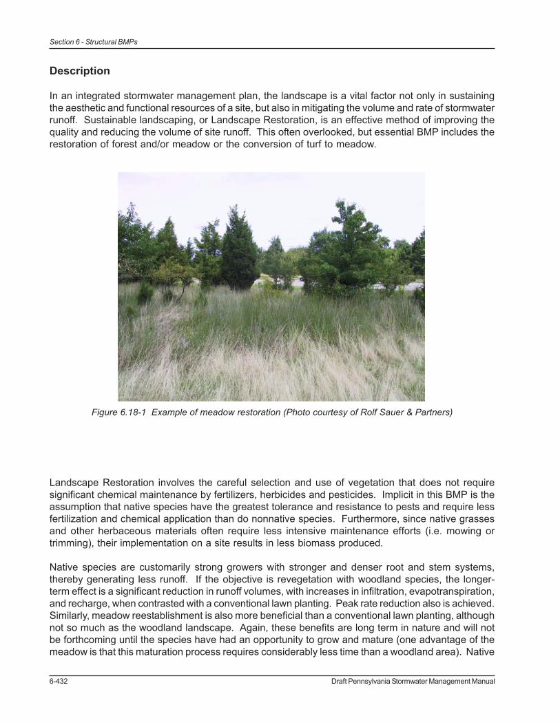
6-432 Draft Pennsylvania Stormwater Management Manual
Section 6 - Structural BMPs
Description
In an integrated stormwater management plan, the landscape is a vital factor not only in sustainingthe aesthetic and functional resources of a site, but also in mitigating the volume and rate of stormwaterrunoff. Sustainable landscaping, or Landscape Restoration, is an effective method of improving thequality and reducing the volume of site runoff. This often overlooked, but essential BMP includes therestoration of forest and/or meadow or the conversion of turf to meadow.
Landscape Restoration involves the careful selection and use of vegetation that does not requiresignificant chemical maintenance by fertilizers, herbicides and pesticides. Implicit in this BMP is theassumption that native species have the greatest tolerance and resistance to pests and require lessfertilization and chemical application than do nonnative species. Furthermore, since native grassesand other herbaceous materials often require less intensive maintenance efforts (i.e. mowing ortrimming), their implementation on a site results in less biomass produced.
Native species are customarily strong growers with stronger and denser root and stem systems,thereby generating less runoff. If the objective is revegetation with woodland species, the longer-term effect is a significant reduction in runoff volumes, with increases in infiltration, evapotranspiration,and recharge, when contrasted with a conventional lawn planting. Peak rate reduction also is achieved.Similarly, meadow reestablishment is also more beneficial than a conventional lawn planting, althoughnot so much as the woodland landscape. Again, these benefits are long term in nature and will notbe forthcoming until the species have had an opportunity to grow and mature (one advantage of themeadow is that this maturation process requires considerably less time than a woodland area). Native
Figure 6.18-1 Example of meadow restoration (Photo courtesy of Rolf Sauer & Partners)

Draft Pennsylvania Stormwater Management Manual 6-433
Section 6 - Structural BMPs
grasses also tend to have substantially deeper roots and more root mass than turf grasses, whichresults in:
• A greater volume of water uptake (evapotranspiration)• Improved soil conditions through organic material and macropore formation• Provide for greater infiltration
Landscape architects specializing in the local plant community are usually able to identify a variety ofspecies that meet these criteria. As the selection of such materials begins at the conceptual designstage, where lawns are eliminated or avoided altogether and landscaping species selected, LandscapeRestoration can generally result in a site with reduced runoff volume and rate, as well as significantnonpoint source load reduction/prevention.
Landscape Restoration can improve water quality preventively by minimizing application of fertilizersand pesticides/herbicides. Given the high rates of chemical application which have been documentedat newly created maintained areas for both residential and nonresidential land uses, eliminating theopportunity for chemical application is important for water quality – perhaps the most effectivemanagement technique. Of special importance here is the reduction in fertilization and nitrate loadings.For example, Delaware’s Conservation Design for Stormwater Management lists multiple studiesthat document high fertilizer application rates, including both nitrogen and phosphorus, in newlycreated landscapes in residential and nonresidential land developments. Expansive lawn areas inlow density single-family residential subdivisions as well as large office parks – development whichhas and continues to proliferate in Pennsylvania municipalities - typically receives intensive chemicalapplication, both fertilization and pest control, which can exceed application rates being applied toagricultural fields. Avoidance of this nonpoint pollutant source is an important water quality objective.
Figure 6.18-2 Native meadow species are more deeply rooted than turf grass.

6-434 Draft Pennsylvania Stormwater Management Manual
Section 6 - Structural BMPs
Variations• Meadow• No-mow lawn area• Woodland restoration• Removal of existing lawn to reduce runoff volume• Buffers between lawn areas and wetlands or stream corridors• Replacement of “wet” lawn areas difficult to mow• Replacement of hard to maintain lawns under mature trees
Applications
• Forested Landscape/Restoration• Suburban / Developing Landscape• Urban Landscape• Meadow Restoration• Conversion of Turf to Meadow
Design Considerations
1. The recommended guidelines for Landscape Restoration are very closely related to thoseof Riparian Buffer Restoration (RBR). Specifically, Landscape Restoration overlaps withthe guidelines for Zones 2 and 3 in typical RBR. As with RBR, it is essential for successfulLandscape Restoration that site conditions are well understood, objectives of thelandowner are considered, and the appropriate plants are chosen for the site. These areall tasks that are completed in the early planning stages of a project. For a summary of thenine steps that PADEP/DCNR advocates during the planning stages of a restorationproject, see BMP 6.17- Riparian Buffer Restoration. Included in this nine-step process are:analysis of site soils/natural vegetative features/habitat significance/topography/etc.,determination of restoration suitability, and site preparation.
2. In those sites where soils have been disturbed or determined inadequate for restoration(based on analysis), soil amendments are required. Soil amendment and restoration is theprocess of restoring compromised soils by subsoiling and/or adding a soil amendment,such as compost, for the purpose of reestablishing its long-term capacity for infiltration andpollution removal. For more information on restoring soils, see BMP 6.19 SoilAmendments.
3. “Native species” is a broad term. Different types of native species landscapes may becreated, from meadow to woodland areas, obviously requiring different approaches toplanting. A native landscape may take several forms in Pennsylvania, ranging fromreestablishment of woodlands with understory plantings to reestablishment of meadow. Itshould be noted that as native landscapes grow and mature, the positive stormwaterbenefits relating to volume control and peak rate control increase. So, unlike highlymaintained turf lawns, these landscapes become much more effective in reducing runoffvolumes and nonpoint source pollutants over time.
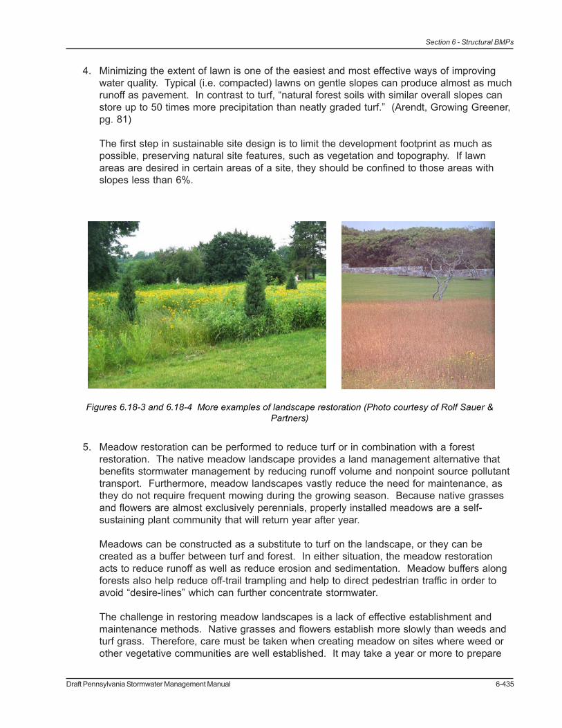
Draft Pennsylvania Stormwater Management Manual 6-435
Section 6 - Structural BMPs
4. Minimizing the extent of lawn is one of the easiest and most effective ways of improvingwater quality. Typical (i.e. compacted) lawns on gentle slopes can produce almost as muchrunoff as pavement. In contrast to turf, “natural forest soils with similar overall slopes canstore up to 50 times more precipitation than neatly graded turf.” (Arendt, Growing Greener,pg. 81)
The first step in sustainable site design is to limit the development footprint as much aspossible, preserving natural site features, such as vegetation and topography. If lawnareas are desired in certain areas of a site, they should be confined to those areas withslopes less than 6%.
5. Meadow restoration can be performed to reduce turf or in combination with a forestrestoration. The native meadow landscape provides a land management alternative thatbenefits stormwater management by reducing runoff volume and nonpoint source pollutanttransport. Furthermore, meadow landscapes vastly reduce the need for maintenance, asthey do not require frequent mowing during the growing season. Because native grassesand flowers are almost exclusively perennials, properly installed meadows are a self-sustaining plant community that will return year after year.
Meadows can be constructed as a substitute to turf on the landscape, or they can becreated as a buffer between turf and forest. In either situation, the meadow restorationacts to reduce runoff as well as reduce erosion and sedimentation. Meadow buffers alongforests also help reduce off-trail trampling and help to direct pedestrian traffic in order toavoid “desire-lines” which can further concentrate stormwater.
The challenge in restoring meadow landscapes is a lack of effective establishment andmaintenance methods. Native grasses and flowers establish more slowly than weeds andturf grass. Therefore, care must be taken when creating meadow on sites where weed orother vegetative communities are well established. It may take a year or more to prepare
Figures 6.18-3 and 6.18-4 More examples of landscape restoration (Photo courtesy of Rolf Sauer &Partners)

6-436 Draft Pennsylvania Stormwater Management Manual
Section 6 - Structural BMPs
the site and to get weeds under control before planting. Erosion prone sites should beplanted with a nurse crop (such as annual rye) for quick vegetation establishment toprevent seed and soil loss. Steep slopes and areas subject to water flow should bestabilized with erosion blankets, selected to mitigate expected runoff volumes andvelocities. Hydro-seeding is not recommended. Additionally, seed quality is extremelyimportant to successful establishment. There is tremendous variation among seedsuppliers, seeds should be chosen with a minimum percent of non-seed plant parts.
Figure 6.18-5. Example of Reforestation (Sauer, 1998)

Draft Pennsylvania Stormwater Management Manual 6-437
Section 6 - Structural BMPs
6. Conversion of turf grass areas to meadow is relatively simple and has enormous benefitsfor stormwater management. Though turf is inexpensive to install, the cost of maintenanceto promote an attractive healthy lawn is high (requiring mowing, irrigation, fertilizer, lime andherbicides) and its effects are detrimental to water quality. Turf areas are good candidatesfor conversion to meadow as they typically have lower density of weed species. Theconversion of turf to meadow requires that all turf be killed before planting, and care mustbe taken to control weed establishment prior to planting.
7. Forest restoration includes planting of appropriate tree species (small saplings) with quickestablishment of an appropriate ground cover around the trees in order to stabilize the soiland prevent colonization of invasive species. Reforestation can be combined with othervolume control BMPs such as retentive berming, vegetated filter strips and swales.
Plant selection should mimic the surrounding native vegetation and expand on the nativespecies composition already found on the site. A mixture of native trees and shrubs isrecommended and should be planted once a ground cover is established.
8. In terms of woodland areas, DNREC’s Conservation Design for Stormwater Managementstates, “…a mixture of young trees and shrubs is recommended…. Tree seedlings from 12to 18 inches in height can be used, with shrubs at 18 to 24 inches. Once a ground covercrop is established (to offset the need for mowing), trees and shrubs should be planted on8-foot centers, with a total of approximately 430 trees per acre. Trees should be plantedwith tree shelters to avoid browse damage in areas with high deer populations, and toencourage more rapid growth.” (p.3-50). Initial watering and weekly watering during dryperiods may be necessary during the first growing season. As tree species grow larger,both shrubs and ground covers recede and yield to the more dominant tree species. Thenative tree species mix of small inexpensive saplings should be picked for variety andshould reflect the local forest communities. Annual mowing to control invasives may benecessary, although the quick establishment of a strong-growing ground cover can beeffective in providing invasive control. Native meadow planting mixes also are available. Avariety of site design factors may influence the type of vegetative community that is to beplanned and implemented. In so many cases, the “natural” vegetation of Pennsylvania’scommunities is, of course, woodlands.
9. Ensure adequate stabilization. Adequate stabilization is extremely important as nativegrasses, meadow flowers, and woodlands establish more slowly than turf. Stabilization canbe achieved for forest restoration by establishing a ground cover before planting of treesand shrubs. When creating meadows, it may be necessary to plant a fast growing nursecrop with meadow seeds for quick stabilization. Annual rye can be planted in the fall orspring with meadow seeds and will establish quickly and usually will not present acompetitive problem. Erosion prone sites should be planted with a nurse crop and coveredwith weed-free straw mulch, while steep slopes and areas subject to runoff should bestabilized with erosion control blankets suitable for the expected volume and velocity ofrunoff.

6-438 Draft Pennsylvania Stormwater Management Manual
Section 6 - Structural BMPs
Volume Reduction Calculations and Peak Rate MitigationAreas designated for landscape restoration should be considered as “Meadow, good condition” instormwater calculations.
Water Quality ImprovementSee Section 9 for Water Quality Improvement methodology, which addresses pollutant removaleffectiveness of this BMP.
Construction Sequence
Forest restoration installation follows closely the procedure outlined in BMP 6.17- Riparian BufferRestoration. Refer to BMP 6.17 for detailed information, with the understanding that species selectionfor upland forest restoration will differ from that for riparian restoration.
Meadow installation should proceed as follows:
1. SELECT SITE· Confirm site is suitable for restoration, should be sunny, open and well-ventilated. Meadow
plants require at least a half a day of full sun.· Obtain landowner permission
2. ANALYZE SITE· Evaluate site’s physical conditions (soil attributes, geology, terrain)· Evaluate site’s vegetative features (desirable and undesirable species, native species,
sensitive habitats). Good candidates for meadow plantings include areas presently in turf,cornfields, soybean fields, alfalfa fields and bare soils from new construction.
· Areas with a history of heavy weed growth may require a full year or longer to prepare forplanting.
· Beware of residual herbicides that may have been applied to agricultural fields. Alwayscheck the herbicide history of the past 2-3 years and test the soils if in doubt.
3. PLANT SELECTION· Select plants that are well adapted to the specific site conditions. Meadow plants must be
able to out compete weed species in the first few years as they become established.
4. PREPARE SITE· All weeds or existing vegetation must be eliminated prior to seeding.· Perennial weeds may require year long smothering, repeated sprayings with herbicides, or
repeated tillage with equipment that can uproot and kill perennial weeds.
5. PLANTING DAY· Planting can take place from Spring thaw through June 30 or from September 1 through
soil freeze-up (“dormant seeding”)· Planting in July and August is generally not recommend due to the frequency of drought
during this time.· Seeding can be accomplished by a variety of methods: no-till seeder for multi-acre
planting; broadcast seeder; hand broadcast for small areas of one acre or less.· Seed quality is critical and a seed mix should be used with a minimum percentage of non-
seed plant parts.

Draft Pennsylvania Stormwater Management Manual 6-439
Section 6 - Structural BMPs
7. SITE MAINTENANCE (additional information below)· Assign responsibilities watering, weeding, mowing, and maintenance· Monitor site regularly for growth and potential problems
Maintenance Issues
Meadows and Forests are low maintenance but not “no maintenance”. They usually require morefrequent maintenance in the first few years immediately following installation.
Forest restoration areas planted with a proper cover crop can be expected to require annual mowingin order to control invasives. Application of a carefully selected herbicide (Roundup or similarglyphosate herbicide) around the protective tree shelters/tubes may be necessary, reinforced byselective cutting/manual removal, if necessary. This initial maintenance routine is necessary for theinitial 2 to 3 years of growth and may be necessary for up to 5 years until tree growth and tree canopybegins to form, naturally inhibiting weed growth (once shading is adequate, growth of invasives andother weeds will be naturally prevented, and the woodland becomes self-maintaining). Review of thenew woodland should be undertaken intermittently to determine if replacement trees should be provided(some modest rate of planting failure is usual).
Meadow management is somewhat more straightforward; a seasonal mowing or burning may berequired, although care must be taken to make sure that any management is coordinated with essentialreseeding and other important aspects of meadow reestablishment. In the first year weeds must becarefully controlled and consistently mowed back to 4-6 inches tall when they reach 12 inches inheight. In the second year, weeds should continue to monitored and mowed and rhizomatousweeds should be hand treated with herbicide. Weeds should not be sprayed with herbicide as thedrift from the spray may kill large patches of desirable plants, allowing weeds to move in to these newopen areas. In the beginning of the third season, the young meadow should be burned off in mid-spring. If burning is not possible, the meadow should be mowed very closely to the ground instead.The mowed material should be removed from the site to expose the soil to the sun. This helpsencourage rapid soil warming which favors the establishment of “warm season” plants over “coolseason” weeds.
Cost Issues
Landscape restoration cost implications are minimal during construction. Seeding for installation ofa conventional lawn is likely to be less expensive than planting of a “cover” of native species, althoughwhen contrasted with a non-lawn landscape, “natives” often are not more costly than other nonnativelandscape species. In terms of woodland creation, somewhat dated (1997) costs have been providedby the Chesapeake Bay Riparian Handbook: A Guide for Establishing and Maintaining RiparianForest Buffers:
$860/acre trees with installation$1,600/acre tree shelters/tubes and stakes$300/acre for four waterings on average
In current dollars, these values would be considerably higher, well over $3,000/acre for installationcosts. Costs for meadow reestablishment are lower than those for woodland, in part due to the

6-440 Draft Pennsylvania Stormwater Management Manual
Section 6 - Structural BMPs
elimination of the need for shelters/tubes. Again, such costs can be expected to be greater thaninstallation of conventional lawn (seeding and mulching), although the installation cost differencesdiminish when conventional lawn seeding is redefined in terms of conventional planting beds.
Cost differentials grow greater when longer term operating and maintenance costs are taken intoconsideration. If lawn mowing can be eliminated, or even reduced significantly to a once per yearrequirement, substantial maintenance cost savings result, often in excess of $1,500 per acre peryear. If chemical application (fertilization, pesticides, etc.) can be eliminated, substantial additionalsavings result with use of native species. These reductions in annual maintenance costs resultingfrom a native landscape reestablishment very quickly outweigh any increased installation costs thatare required at project initiation. Unfortunately, because developers pay for the installation costsand longer term reduced maintenance costs are enjoyed by future owners, there is reluctance toembrace native landscaping concepts.
Specifications
The following specifications are provided for information purposes only. These specifications includeinformation on acceptable materials for typical applications, but are by no means exclusive or limiting.The designer is responsible for developing detailed specifications for individual design projects inaccordance with the project conditions.
1. Topsoil – See Appendix C2. Vegetation – See Appendix B

Draft Pennsylvania Stormwater Management Manual 6-441
Section 6 - Structural BMPs
References
Bowman’s Hill Wildflower Preserve, Washington Crossing Historic Park, PO Box 685, New Hope,PA 18938-0685, Tel (215) 862-2924, Fax (215) 862-1846, Native plant reserve, plant sales,native seed, educational programs, www.bhwp.org
Morris Arboretum of the University of Pennsylvania; 9414 Meadowbrook Avenue, Philadelphia, PA19118, Tel (215) 247-5777, www.upenn.edu/morris, PA Flora Project Website: Arboretum andgardens (some natives), educational programs, PA Flora Project, www.upenn.edu/paflora
Pennsylvania Department of Conservation and Natural Resources; Bureau of Forestry; PO Box8552, Harrisburg, PA 17105-8552, Tel (717)787-3444, Fax (717)783-5109, Invasive plant brochure;list of native plant and seed suppliers in PA; list of rare, endangered, threatened species.
Pennsylvania Native Plant Society, 1001 East College Avenue, State College, PA 16801www.pawildflower.org
Western Pennsylvania Conservancy; 209 Fourth Avenue, Pittsburgh, PA 15222, Tel (412) 288-2777,Fax (412) 281-1792, www.paconserve.org
Conservation Design for Stormwater Management (DNREC and EMC)
Stream ReLeaf Plan and Toolkits
The Once and Future Forest – Leslie Sauer
Forestry Best Management Practices for Water Quality – Virginia Department of Forestry
Chesapeake Bay Riparian Handbook: A Guide for Establishing and Maintaining Riparian ForestBuffers (1997)
Growing Greener, Arendt
Diboll, Neil. Five Steps to Successful Prairie Meadow Establishment. Windstar Wildlife Institute.
Penn State College of Agricultural Sciences, Agricultural Research and Cooperation Extension. “Pennsylvania Wildlife No. 12: Warm-season Grasses and Wildlife” and “Pennsylvania WildlifeNo. 5: Meadows and Prairies: Wildlife-friendly Alternatives to Lawn”
Arendt, Growing Greener, pg. 81

6-442 Draft Pennsylvania Stormwater Management Manual
Section 6 - Structural BMPs

Draft Pennsylvania Stormwater Management Manual 6-443
Section 6 - Structural BMPs
Restoration BMPsBMP 6.19: Soil Amendment & Restoration
Soil amendment and restoration isthe process of restoring disturbedsoils by restoring soil porosity and/or adding a soil amendment, suchas compost, for the purpose ofreestablishing the soil’s long-termcapacity for infiltration and pollutionremoval.
Pollutant Removal
Stormwater FunctionsLow/MedLowMedMed
Volume Reduction:Recharge:
Peak Rate Control:Water Quality:
Potential Applications
Residential:Commercial:Ultra Urban:
Industrial:Retrofit:
Highway/Road:
YESYESYESYESYESYES
Key Design Elements
• Existing soil conditions should be evaluated beforeforming a restoration strategy.
• Physical loosening of the soil, often called subsoiling, ortilling, can treat compaction.
• The combination of subsoiling and soil amendment isoften the more effective strategy.
• Compost amendments increase water retention.
85%85%50%
TSS:TP:
NO3:

6-444 Draft Pennsylvania Stormwater Management Manual
Section 6 - Structural BMPs
Problem Description
Animals, farm equipment, trucks, constructionequipment, cars, and people causecompaction. Wet soil compacts easier than drysoil. Natural compaction occurs due to specialchemical or physical properties, and theseoccurrences are called “hard pans”. A typicalsoil after compaction has strength of about6,000 kPa, while studies have shown that rootgrowth is not possible beyond 3,000 kPa.
Different Types of Compaction
1) Minor Compaction – surface compaction within 8-12” due to contact pressure, axle load >10 tons can compact through root zone, up to 1’ deep
2) Major Compaction – deep compaction, contact pressure and total load, axle load > 20 tonscan compact up to 2’ deep (usually large areas compacted to increase strength for pavingand foundation with overlap to “lawn” areas)
In general, compaction problems occur when airspace drops to 10-15% of total soil volume.Compaction affects the infiltrating and water quality capacity of soils. When soils are compacted, thesoil particles are pressed together, reducing the pore space necessary to move air and water throughoutthe soil. (Figure 2 above.) This decrease in porosity causes an increase in bulk density (weight ofsolids per unit volume of soil). The greater the bulk density, the lower the infiltration and therefore thelarger volume of runoff.
Different types of soils have bulk density levels at which compaction starts to limit root growth. Whenroot growth is limited, the uptake of water and nutrients by vegetation is reduced.
Figure 6.19-2. Comparison showing good to poor physical soil conditions
Figure 6.19-1. Soil compaction and cutting duringconstruction.
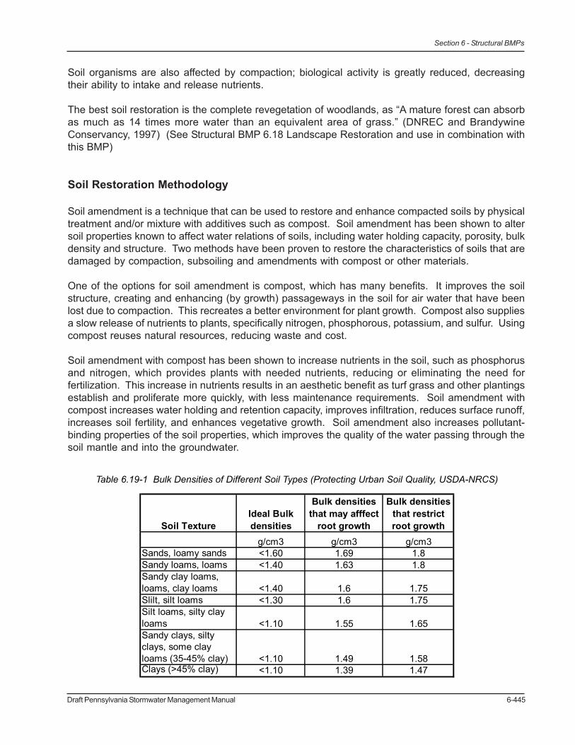
Draft Pennsylvania Stormwater Management Manual 6-445
Section 6 - Structural BMPs
Soil organisms are also affected by compaction; biological activity is greatly reduced, decreasingtheir ability to intake and release nutrients.
The best soil restoration is the complete revegetation of woodlands, as “A mature forest can absorbas much as 14 times more water than an equivalent area of grass.” (DNREC and BrandywineConservancy, 1997) (See Structural BMP 6.18 Landscape Restoration and use in combination withthis BMP)
Soil Restoration Methodology
Soil amendment is a technique that can be used to restore and enhance compacted soils by physicaltreatment and/or mixture with additives such as compost. Soil amendment has been shown to altersoil properties known to affect water relations of soils, including water holding capacity, porosity, bulkdensity and structure. Two methods have been proven to restore the characteristics of soils that aredamaged by compaction, subsoiling and amendments with compost or other materials.
One of the options for soil amendment is compost, which has many benefits. It improves the soilstructure, creating and enhancing (by growth) passageways in the soil for air water that have beenlost due to compaction. This recreates a better environment for plant growth. Compost also suppliesa slow release of nutrients to plants, specifically nitrogen, phosphorous, potassium, and sulfur. Usingcompost reuses natural resources, reducing waste and cost.
Soil amendment with compost has been shown to increase nutrients in the soil, such as phosphorusand nitrogen, which provides plants with needed nutrients, reducing or eliminating the need forfertilization. This increase in nutrients results in an aesthetic benefit as turf grass and other plantingsestablish and proliferate more quickly, with less maintenance requirements. Soil amendment withcompost increases water holding and retention capacity, improves infiltration, reduces surface runoff,increases soil fertility, and enhances vegetative growth. Soil amendment also increases pollutant-binding properties of the soil properties, which improves the quality of the water passing through thesoil mantle and into the groundwater.
Table 6.19-1 Bulk Densities of Different Soil Types (Protecting Urban Soil Quality, USDA-NRCS)
Soil TextureIdeal Bulk densities
Bulk densities that may afffect
root growth
Bulk densities that restrict root growth
g/cm3 g/cm3 g/cm3Sands, loamy sands <1.60 1.69 1.8Sandy loams, loams <1.40 1.63 1.8Sandy clay loams, loams, clay loams <1.40 1.6 1.75Slilt, silt loams <1.30 1.6 1.75Silt loams, silty clay loams <1.10 1.55 1.65Sandy clays, silty clays, some clay loams (35-45% clay) <1.10 1.49 1.58Clays (>45% clay) <1.10 1.39 1.47

6-446 Draft Pennsylvania Stormwater Management Manual
Section 6 - Structural BMPs
The second method is tilling, which involves the digging, scraping, and mixing, and ripping of soil withthe intent of circulating air into the soil mantle in various layers. Compaction down to 20 inches oftenrequires ripping for soil restoration. Tilling exposes compacted soil devoid of oxygen to air andrecreates temporary air space.
Bulk density field tests indicate the compaction level of soils.
Variations
• Soil amendment media can include compost, sand, and manufactured microbial solutions.• Seed can be included in the soil amendment to save application time.
Applications
• New Development (Residential, Commercial, Industrial) – new lawns can be amendedwith compost and not heavily compacted before planting, to increase the porosity of thesoils.
• Urban Retrofits - Tilling of soils that have been compacted before it is converted intomeadow, lawn, or a stormwater facility is recommended.
• Detention Basin Retrofits – The inside face of detention basins is usually heavilycompacted, and tilling the soil mantle will encourage infiltration to take place. Tilling maybe necessary to establish better vegetative cover.
• Landscape Maintenance – compost can substitute for dwindling supplies of native topsoilin urban areas.
• Golf Courses – Using compost as part of the landscaping upkeep on the greens has beenshown to alleviate soil compaction erosion, and turf disease problems.
Design Considerations
1. Treating Compaction by Soil Amendmenta) Soil amendment media can include compost, mulch, manures, sand, and manufactured
microbial solutions.b) Soils should be amended at about a 2:1 ratio of soil to amendment, unless a proprietary
product is used, and in this case the manufacturer’s instructions should be followed interms of mixing and application rate.
c) Soil amendments should not be used on slopes greater than 30%. In these areas, deep-rooted vegetation can be used to increase stability.
d) Soil amendment should not take place within the drip line of a tree to avoid damaging theroot system.
e) On-site soils with an organic content of at least 5 percent can be properly stockpiled (tomaintain organic content) and reused to amend soils, saving costs.

Draft Pennsylvania Stormwater Management Manual 6-447
Section 6 - Structural BMPs
f) Procedure: rototill, or rip the subgrade, remove rocks, distribute the compost, spread thenutrients, rototill again.
g) Add 6 inches compost / amendment and till up to 8 inches for minor compaction.h) Add 10 inches compost / amendment and till up to 20 inches for major compaction.
2. Treating Compaction by Ripping / Subsoiling / Tilling / Scarificationa) Subsoiling is only effective when performed on dry soils.b) Ripping, subsoiling, or scarification of the subsoil should be performed where subsoil has
become compacted by equipment operation, dried out and crusted, or where necessary toobliterate erosion rills.
c) Ripping (Subsoiling) should be performed using a solid-shank ripper and to a depth of 20inches, (8 inches for minor compaction).
d) Should be performed before compost is placed and after any excavation is completed.e) Subsoiling should not be performed within the drip line of any existing trees, over
underground utility installations within 30 inches of the surface, where trenching/drainagelines are installed, where compaction is by design, and on inaccessible slopes.
Subsoiling should not be performed with common tillage tools such as a disk or chisel plow becausethey are too shallow and can compact the soil just beneath the tillage depth.
3. Other methodologies:a) Irrigation Management – low rates of water should be applied, as over-irrigation wastes
water and may lead to environmental pollution from lawn chemicals, nutrients, andsediment.
b) Limited mowing – higher grass corresponds to greater evapotranspiration.c) Compost can be amended with bulking agents, such as aged crumb rubber from used tires
or weed chips. This can be a cost-effective alternative that reuses waste materials.d) In areas where compaction is less severe (not as a result of heavy construction
equipment), planting with deep-rooted perennials can treat compaction, howeverrestoration takes several years.
Figure 6.19-3. Results showing mean runoff and mean time to initiate runoff from unvegetated test plots,Source: http://www.forester.net/ecm_0405_studies.html

6-448 Draft Pennsylvania Stormwater Management Manual
Section 6 - Structural BMPs
Detailed Stormwater Functions
Infiltration Area (If needed)The infiltration area will be the entire area restored, depending on the existing soil conditions, and therestoration effectiveness.
Volume Reduction CalculationsSoil Amendments can reduce the need for irrigation by retaining water and slowly releasing moisture,which encourages deeper rooting. Infiltration is increased; therefore the volume of runoff is decreased.
Compost amended soils can significantly reduce the volume of stormwater runoff. For soils thathave either been compost amended according to the recommendations of their BMP, or subject torestoration such that the field measured bulk densities meet the Ideal Bulk Densities of Table 1, thefollowing volume reduction may be applied:
Amended Area (ft2) x 0.50in x 1/12 = Volume (cf)
Peak Rate MitigationSee Section 9 for peak rate mitigation.
Water Quality ImprovementSee Section 9 for water quality improvement.
Figure 6.19-4. Surface runoff rates reduced by compostapplication (http://www.tucson.ars.ag.gov/icrw/Proceedings/
Tyler.pdf)

Draft Pennsylvania Stormwater Management Manual 6-449
Section 6 - Structural BMPs
Construction Sequence
1. All construction should be completed and stabilized before beginning soil restoration.
Maintenance Issues
The soil restoration process by need to be repeated over time, due to compaction by use and/orsettling. (For example, playfields or park areas will be compacted by foot traffic.)
Cost Issues
Tilling costs, including scarifying sub-soils, range from $800/ac to $1000/ac.
Compost amending of soil ranges in cost from $860/ac to $1000/ac.
Figure 6.19-5. Results showing adsorbed nutrient and metal mass in unvegetated plot runoff(Source: http://www.forester.net/ecm_0405_studies.html)
6-450 Draft Pennsylvania Stormwater Management Manual
Section 6 - Structural BMPs
Specifications
The following specifications are provided for information purposes only. These specifications includeinformation on acceptable materials for typical applications, but are by no means exclusive or limiting.The designer is responsible for developing detailed specifications for individual design projects inaccordance with the project conditions.
1. SCOPE
a. This specification covers the use of compost for soil amendment and themechanical restoration of compacted, eroded and non-vegetated soils. Soilamendment and restoration is necessary where existing soil has been deemedunhealthy in order to restore soil structure and function, increase infiltration potentialand support healthy vegetative communities.
b. Soil amendment prevents and controls erosion by enhancing the soil surface toprevent the initial detachment and transport of soil particles.
2. COMPOST MATERIALS
a. Compost products specified for use in this application are described in Table 1. Theproduct’s parameters will vary based on whether vegetation will be established onthe treated slope.
b. Only compost products that meet all applicable state and federal regulationspertaining to its production and distribution may be used in this application.Approved compost products must meet related state and federal chemicalcontaminant (e.g., heavy metals, pesticides, etc.) and pathogen limit standardspertaining to the feedstocks (source materials) in which it is derived.
c. Very coarse compost should be avoided for soil amendment as it will make plantingand crop establishment more difficult.
d. Note 1 - Specifying the use of compost products that are certified by the U.S.Composting Council’s Seal of Testing (STA) Program (www.compostingcouncil.org)will allow for the acquisition of products that are analyzed on a routine basis, usingthe specified test methods. STA participants are also required to provide a standardproduct label to all customers, allowing easy comparison to other products.
3. SUB-SOILING TO RELIEVE COMPACTION
a. Before the time the compost is placed and preferably when excavation iscompleted, the subsoil shall be in a loose, friable condition to a depth of 20 inchesbelow final topsoil grade and there shall be no erosion rills or washouts in thesubsoil surface exceeding 3 inches in depth.
b. To achieve this condition, subsoiling, ripping, or scarification of the subsoil will berequired as directed by the owners s representative, wherever the subsoil has beencompacted by equipment operation or has become dried out and crusted, and

Draft Pennsylvania Stormwater Management Manual 6-451
Section 6 - Structural BMPs
where necessary to obliterate erosion rills. Sub-soiling shall be required to reducesoil compaction in all areas where plant establishment is planned. Sub-soiling shallbe performed by the prime or excavating contractor and shall occur before compostplacement.
c. Subsoiled areas shall be loosened to less than 1400 kPa (200 psi) to a depth of 20inches below final topsoil grade. When directed by the owner’s representative, theContractor shall verify that the sub-soiling work conforms to the specified depth.
d. Sub-soiling shall form a two-directional grid. Channels shall be created by acommercially available, multi-shanked, parallelogram implement (solid-shankripper). The equipment shall be capable of exerting a penetration force necessaryfor the site. No disc cultivators chisel plows, or spring-loaded equipment will beallowed. The grid channels shall be spaced a minimum of 12 inches to a maximumof 36 inches apart, depending on equipment, site conditions, and the soilmanagement plan. The channel depth shall be a minimum of 20 inches or asspecified in the soil management plan. If soils are saturated, the Contractor shalldelay operations until the soil will not hold a ball when squeezed. Only one passshall be performed on erodible slopes greater than 1 vertical to 3 horizontal. Whenonly one pass is used, work shall be at right angles to the direction of surfacedrainage, whenever practical.
e. Exceptions to sub-soiling include areas within the drip line of any existing trees,over utility installations within 30 inches of the surface, where trenching/drainagelines are installed, where compaction is by design (abutments, footings, or inslopes), and on inaccessible slopes, as approved by the owner’s representative. Incases where exceptions occur, the Contractor shall observe a minimum setback of20 feet or as directed by the owner’s representative. Archeological clearances maybe required in some instances.
4. COMPOST SOIL AMENDMENT QUALITY
a. The final, resulting compost soil amendment must meet all of the mandatory criteriain Table 2.
5. COMPOST SOIL AMENDMENT INSTALLATION
a. Spread 2-3 inches of approved compost on existing soil. Till added soil into existingsoil with a rotary tiller that is set to a depth of 6 inches. Add an additional 4 inches ofapproved compost to bring the area up to grade.
b. After permanent planting/seeding, 2-3 inches of compost blanket will be applied toall areas not protected by grass or other plants

6-452 Draft Pennsylvania Stormwater Management Manual
Section 6 - Structural BMPs
References
“The Compaction of Urban Soils”, Technical Note #107 from Watershed Protection Techniques,Article 36, 3(2): 661-665.
Dallas, H. and A. Lewandowski, 2003. Protecting Urban Soil Quality: Examples for LandscapeCodes and Specifications. USDA Natural Resources Conservation Services.
OCSCD, 2001. Impact of Soil Disturbance During Construction on Bulk Density and Infiltration inOcean County, New Jersey. Ocean County Soil Conservation District, Schnabel EngineeringAssoicates, Inc., USDA Natural Resources Conservation Services. www.ocscd.org.
Pitt, R. et al., 2002. “Compacted Urban Soils Effects on Infiltration and Bioretention StormwaterControl Designs.”
Pitt, R. et al., 2002. “Infiltration Through Disturbed Urban Soils and compost-Amended Soil Effectson Runoff Quality and Quantity.”
“The Relationship Between Soil and Water”, Soils for Salmon, The Urban Environment, 1999
“Soil Quality Resource Concerns: Compaction”, USDA Natural Resources Conservation Service,1996
“Soil Quality Resource Concerns: Available Water Capacity”, USDA Natural Resources ConservationService, 1998
“Specifications for Soil Amendments”, Low Impact Development Center, Inc., www.lid-stormwater.net/soilamend/soilamend_specs.htm
“Urban Soil Compaction”, Soil Quality – Urban Technical Note, No. 2, USDA Natural ResourcesConservation Services, 2000.
DNREC and Brandywine Conservancy, 1997

Draft Pennsylvania Stormwater Management Manual 6-453
Section 6 - Structural BMPs
6.8 Other BMPs and Related Structural Measures

6-454 Draft Pennsylvania Stormwater Management Manual
Section 6 - Structural BMPs
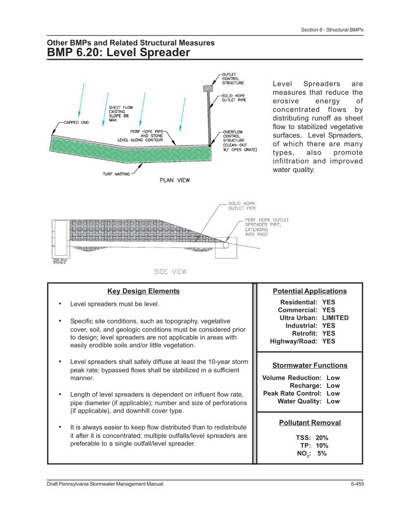
Draft Pennsylvania Stormwater Management Manual 6-455
Section 6 - Structural BMPs
Other BMPs and Related Structural MeasuresBMP 6.20: Level Spreader
Level Spreaders aremeasures that reduce theerosive energy ofconcentrated flows bydistributing runoff as sheetflow to stabilized vegetativesurfaces. Level Spreaders,of which there are manytypes, also promoteinfiltration and improvedwater quality.
Pollutant Removal
Stormwater Functions
Potential ApplicationsKey Design Elements
• Level spreaders must be level.
• Specific site conditions, such as topography, vegetativecover, soil, and geologic conditions must be considered priorto design; level spreaders are not applicable in areas witheasily erodible soils and/or little vegetation.
• Level spreaders shall safely diffuse at least the 10-year stormpeak rate; bypassed flows shall be stabilized in a sufficientmanner.
• Length of level spreaders is dependent on influent flow rate,pipe diameter (if applicable); number and size of perforations(if applicable), and downhill cover type.
• It is always easier to keep flow distributed than to redistributeit after it is concentrated; multiple outfalls/level spreaders arepreferable to a single outfall/level spreader.
20%10% 5%
TSS:TP:
NO3:
LowLowLowLow
Volume Reduction:Recharge:
Peak Rate Control:Water Quality:
Residential:Commercial:Ultra Urban:
Industrial:Retrofit:
Highway/Road:
YESYESLIMITEDYESYESYES

6-456 Draft Pennsylvania Stormwater Management Manual
Section 6 - Structural BMPs
Description
Ensuring distributed, non-erosive flow conditions is an important consideration in any stormwatermanagement strategy and particularly critical to the performance of certain BMPs (e.g. filter strips).Traditionally, stormwater discharges have been stabilized (i.e. diffused) with structural measuressuch as riprap. While riprap typically affords a high degree of protection for significant flow conditionsand requires little maintenance, it can be expensive, result in damaging heat gain in runoff, and maybe an unnecessary waste of natural resources. By promoting concentrated releases of runoff, riprapalso fails to encourage infiltration or improve water quality, other than diffusing erosive flows. On thecontrary, level spreading devices diffuses flows (both low and high), promote infiltration, and improvewater quality by evenly distributing flows over a stabilized vegetated surface. There are many differenttypes and functions of level spreaders. Examples include concrete sills (or lips), curbs, earthenberms, and level perforated pipes.
For the purposes of the Manual, there are essentially two categories of level spreaders. The firsttype of level spreader (Inflow) is meant to evenly distribute flow entering into another structural BMP,such as a filter strip, infiltration basin, or vegetated swale, for example. Examples of this type of levelspreader include concrete sills (or lips), curbs, and earthen berms. The second type of level spreader(Outflow) is intended to reduce the erosive force of high flows while at the same time enhancingnatural infiltration opportunities. Examples of this second type include a level, perforated pipe in ashallow aggregate trench (similar to an Infiltration Trench) and earthen berms. While the first type oflevel spreader can be a very effective measure, it is already discussed in some detail as a designconsideration in other structural BMPs and particularly in BMP 6.10 Infiltration Berms. This sectiontherefore, focuses primarily on the second category of level spreaders.
Outflow level spreaders, the second category, are often used in conjunction with other structuralBMPs, such as BMP 6.2 Infiltration Basins and BMP 6.3 Subsurface Infiltration Bed. However, incertain situations, they can be used as “stand alone” BMPs to “treat” runoff from roofs or otherimpervious areas. In either case, level spreaders will account for some level of volume and ratereduction, the degree to which depends on the specific design, natural infiltration rate of the soil,amount of influent runoff, vegetation density and slope of downhill area, and extent (length). Specificcredit, as defined in BMPs 5.11 and 5.12, is given to stand alone level spreaders for imperviousareas greater than 500 square feet.
A typical level spreader that is used in conjunction with another structural BMP is a level perforatedpipe in a shallow aggregate trench. Though the actual design will vary, a “level spreader pipe” shallbe designed to at least distribute to the 10-year storm. Depending on the computed flow rate andavailable space, the designer may provide enough length of pipe to distribute the 100-year storm(see Design Considerations). If space is limited, then flows above the 10-year storm may be allowedto bypass the level spreader. The level spreader pipe must be installed evenly along a contour at ashallow depth in order to ensure adequate flow distribution and discourage channelization. In somecases, a level spreader pipe may be “upgraded” to an Infiltration Trench if additional volume and ratereduction is required (see BMP 6.4, Infiltration Trench).
The condition of the area downhill of a level spreader must be considered prior to installation. Forinstance, the slope, density and condition of vegetation, natural topography, and length (in the directionof flow) will all affect the effectiveness of a distributed flow measure. Areas immediately downhillfrom a level spreader may need to be stabilized, especially if they have been recently disturbed.Erosion control matting and/or compost blanketing are the recommended measures for temporary

Draft Pennsylvania Stormwater Management Manual 6-457
Section 6 - Structural BMPs
and permanent downhill stabilization. Manufacturer’s specifications shall be followed for chosenstabilization measure.
Variations
• Inflow Level SpreadersEvenly distribute flow entering into another structural BMP, such as a filter strip, infiltrationbasin, or vegetated swale. Examples include concrete sills (or lips), curbs, concrete troughs,½ pipes, short standing PVC-silt fence, aggregate trenches, and earthen berms (see InfiltrationBerms and Filter Strips). To ensure even distribution of flow, it is critical that these devices beinstalled as levelly as possible. More rigid structures (concrete, wood, etc.) are often preferableto earthen berms, which have the potential to erode.
Figure 6.20-1. Concrete Level Spreader distributes flow entering infiltration basin
Figure 6.20-2. Aggregate Trench Level Spreader distributes flow entering filter strip

6-458 Draft Pennsylvania Stormwater Management Manual
Section 6 - Structural BMPs
• Outflow Level Spreaders (in conjunction with structural BMP)Reduces the erosive force of high flows while at the same time enhancing natural infiltrationopportunities. Examples of this second type include a level perforated pipe in a shallowaggregate trench (similar to an Infiltration Trench) and earthen berms.
Figure 6.20-4. Earthen Berm Level Spreader at toe of filter strip
Figure 6.20-3. Level Spreader Perforated Pipe in aggregate trench at pipe outlet

Draft Pennsylvania Stormwater Management Manual 6-459
Section 6 - Structural BMPs
• Outflow Level Spreader (stand alone)Distribute runoff from roofs or other impervious areas of 500 square feet or more. Unlessmodified to approximate an Infiltration Trench, stand-alone level spreaders do not usuallyaccount for substantial volume or rate reductions. However, if designed and installed properly,they still represent effective flow diffusion/infiltration devices with water quality benefits.
Applications
• Ultimate outlet from structural BMPs
• Roof downspout connections (roof area > 500sf
• Inlet connections (impervious area > 500sf)
• Inflow to structural BMP, such as filter strip, infiltration basin, vegetated swale
Design Considerations
1. It is always preferable to not initially concentrate stormwater and provide as many outfalls aspossible. This can reduce or even eliminate the need for engineered devices to provide evendistribution of flow.
2. Receiving soils and land cover should be undisturbed, else sufficiently stabilized with erosion
Figure 6.20-5. Example of stand-alone Outflow Level Spreader in shallow trench in the woods

6-460 Draft Pennsylvania Stormwater Management Manual
Section 6 - Structural BMPs
control matting or compost blanketing. Level spreaders are not applicable in areas witheasily erodable soils and/or little vegetation. The slope below the level spreader shall berelatively smooth in the direction of flow to discourage channelization. The minimum length ofthe receiving area shall be 75 feet.
3. For design considerations of earthen berm level spreaders refer to BMP 6.10 Infiltration Berm.
4. Level spreaders should not be constructed in newly deposited fill dirt. Undisturbed virgin soilis much more resistant to erosion than fill.
5. Most variations of level spreader should not be used for sediment removal. Significant sedimentdeposition in a level spreader will render it ineffective.
6. A perforated pipe level spreader may range in size from 4 to 12 inches in diameter. The pipeis typically laid in an aggregate envelope, the thickness of which is left to the discretion of theEngineer. As previously stated, a deeper trench will provide additional volume reduction andshall be included in such calculations (see BMP 6.4 Infiltration Trench). Non-woven geotextileis typically placed below the aggregate to discourage clogging by sediment. Leaf litter maybe used as an alternative to aggregate.
7. The length of level spreaders is primarily a function of the calculated influent flow rate. Thelevel spreader shall be long enough to freely discharge the desired flow rate. At a minimum,the desired flow rate shall be that resulting from a 10-year design storm. This flow rate shallbe safely diffused without the threat of failure (i.e. creation of erosion, gullies, or rills). Diffusionof the storms greater than the 10-year storm is possible only if space permits. Generally, levelspreaders should have a minimum length of ten feet and a maximum length of 200 feet.
Figure 6.20-6. Example of Level Spreader Pipe

Draft Pennsylvania Stormwater Management Manual 6-461
Section 6 - Structural BMPs
Conventional level spreaders designed to diffuse all flow rates shall be sized based on thefollowing:
For grass or thick ground cover vegetation:
a) 13 linear feet of level spreader for every 1 cfs flowb) Slopes of 8% or less from level spreader to toe of slope
For forested areas with little or no ground cover vegetation:
a) 100 linear feet of level spreader for every 1 cfs flowb) Slopes of 6% or less from level spreader to toe of slope
For slopes up to 15% for forested areas and 25% for grass or thick ground cover, levelspreaders may be installed in series. The above recommended lengths shall be followed.
The length of a perforated pipe level spreader may be further refined by determining theperforation discharge per linear of pipe. A level spreader pipe shall safely discharge in adistributed manner at the same rate of inflow. Perforated pipe manufacturers’ specificationsprovide the discharge per linear foot of pipe, though it is typically based on the general equationfor flow through an orifice. Manufacturer’s specifications can be used to find the rightcombination of length and size of pipe. If the number of perforations per linear foot (based onpipe diameter) and average head above the perforations are known, then the flow can bedetermined by the following equation:
L (length of level spreader pipe) = QP / QL
QL (discharge per linear foot) = QO * # of perforations per linear foot of pipe (provided bymanufacturer, based on pipe diameter)
QO (perforation flow rate) = Cd * A * (2 * g * H)^0.5
Q = the free outfall flow rate through one perforation (ft3/sec)Cd = Coefficient of discharge (typically 0.60)A = Cross sectional area of one perforation (ft2)g = 32.2 ft/sec2
H = head, average height of water above perforation (ft) (provided by manufacturer)
For example, the 10- and 100-year design flows for a site were determined to be 2 and 5 cfs,respectively. Assuming a 12-in diameter pipe with thirty-six 0.375-in. diameter perforationsper linear foot and an H value of 0.418 feet, the discharge per linear foot is calculated at0.086 cfs/ft. When the two design flows are divided by the discharge per linear foot, theresulting required lengths are 24 and 59 feet, respectively.
This calculation assumes a free flow condition. Since the level spreader pipe is encased inaggregate (which is around 40% void space) this assumption is usually acceptable. However,for this reason and to account for the potential for clogging of perforations over time, thelength of pipe should be multiplied by minimum factor of safely of 1.1.

6-462 Draft Pennsylvania Stormwater Management Manual
Section 6 - Structural BMPs
8. Flows (> 10-year storm peak rate) may bypass a level spreader in a variety of ways, includingan overflow structure or up-turned ends of pipe. (The ends of the perforated pipe could beturned uphill at a 45-degree angle or more with the ends screened.) Cleanouts/overflowstructures with open grates can also be installed along longer lengths of perforated pipe. Thedesigner shall provide stabilization measures for bypassed flows in a manner consistent withthe Pennsylvania Erosion and Sedimentation Pollution Control Program Manual.
9. Erosion control matting or compost blanketing is recommended immediately downhill andalong the entire length of the level spreader, particularly in those areas that are unstable orhave been recently disturbed by construction activities. Generally, low flows that are diffusedby a level spreader do not require additional stabilization on an already stabilized and vegetatedslope. The installation requirements for erosion control methods will vary according to themanufacturer’s specifications.
There are a variety of permanent erosion control alternatives to riprap currently on the market.Erosion control/reinforcement matting is a manufactured product that combines vegetativegrowth and synthetic materials to reduce the potential for soil erosion on slopes. It is typicallymade of synthetic materials that will not biodegrade and will create a foundation for plantroots to take hold, extending the viability of grass beyond its natural limits.
Compost blankets are an emerging technology that serves a similar function to permanenterosion control matting. When compost is applied as a “blanket” over a disturbed area, itencourages a thicker, more permanent vegetative cover due to its ability to improve theinfrastructure of the soil. Compost blankets reduce runoff volume by holding water in itspores and improve water quality by binding and degrading specific chemical contaminants.
Figures 6.20-7 and 6.20-8. Examples of Compost Blanket (Filtrexx) and Permanent Erosion Control JuteMatting (North American Green website)

Draft Pennsylvania Stormwater Management Manual 6-463
Section 6 - Structural BMPs
Detailed Stormwater Functions
Volume Reduction CalculationsIn general, level spreaders do not substantially reduce runoff volume. However, for levelspreaders designed similar to Infiltration Trenches, a volume reduction can be achieved.Also, for level spreaders serving as stand-alone BMPs (for contributing impervious areasgreater than 500 square feet), volume reduction credits, as discussed in BMPs 5.11 and 5.12,can be achieved for runoff disconnection. The true amount of volume reduction will dependon the length of level spreader, the density of vegetation, the downhill length and slope, thesoil type of the receiving area, and the design runoff. Large areas with heavy, dense vegetationwill absorb most flows, while barren or compacted areas will absorb limited amounts of runoff.See Section 9 for detailed calculation methodologies.
Peak Rate Mitigation CalculationsThe influent peak rate to a level spreader will be diffused (or dissipated) over the length of thelevel spreader; the number of perforations in a level spreader pipe will essentially divide theconcentrated flow into many smaller flows. To be conservative, and to allow for the possibilityof re-convergence, the peak rate should be taken prior to diffusion from the level spreader.See Section 9 for detailed calculation methodologies.
Water Quality Improvement Water quality improvements occur if the area down gradient of the level spreader is vegetated,stabilized, and minimally sloped. See Section 9 for Water Quality Improvement methodology,which addresses pollutant removal effectiveness of this BMP.
Construction Sequence
1. Level spreaders are considered a permanent part of a site’s stormwater management system.Therefore, the uphill development should be stabilized before any dispersing flow techniquesare installed. (If the level spreader is used in the as erosion and sedimentation control measure,it must be reconfigured (flush perforated pipe, clean out all sediment), to its original statebefore use as a permanent stormwater feature.)
2. All contributing stormwater elements (infiltration beds, inlets, outlet control structures, pipes,etc) shall be installed.
3. Perforated pipe should be installed along a contour, with care taken to construct a level bottom.The pipe can be underground in a shallow infiltration trench (see Infiltration Trench for designguidance), or closer to the surface and covered with a thin layer of aggregate or leaf litter. Ifthe perforated pipe is in a trench, excavate to the design dimensions. If the pipe is to be at ornear the surface, some minor excavation or filling may be necessary to maintain a levelbottom.
4. If necessary, install erosion control matting along the length of the level spreader and to adistance downhill, as specified by the manufacturer/supplier. Cover the pipe with clean,uniformly graded coarse aggregate (if on the ground surface).
5. For construction sequence of earthen berms, see BMP 6.10 Infiltration Berm.

6-464 Draft Pennsylvania Stormwater Management Manual
Section 6 - Structural BMPs
Maintenance Issues
Compared with other BMPs, level spreaders require only minimal maintenance efforts, many of whichmay overlap with standard landscaping demands. The following recommendations represent theminimum maintenance effort for level spreaders:
• Catch Basins and Inlets draining to level spreader should be inspected and cleaned on anannual basis.
• The receiving land area should be restored after construction if damaged, to reflect designassumptions about the soil and land cover.
• It is critical that even sheet flow conditions are sustained throughout the life of the levelspreader, as their effectiveness can deteriorate due to lack of maintenance, inadequatedesign/location, and poor vegetative cover.
o Inspection - The area below a level spreader should be inspected for clogging, densityof vegetation, damage by foot or vehicular traffic, excessive accumulations, andchannelization. Inspections shall be made on a quarterly basis for the first two yearsfollowing installation, and then on a biannual basis thereafter. Inspections shall alsobe made after every storm event greater than 1-inch during the establishment period.
o Removal - Sediment and debris shall be routinely removed (but never less than bi-annually), or upon observation, when buildup occurs in the clean outs. Regradingand reseeding may be necessary in the areas below the level spreader. Regradingmay also be required when pools of standing water are observed along the slope. (Inno case shall standing water be tolerated for longer than 72 hours.)
o Vegetation - Maintaining a vigorous vegetative cover on the areas below a levelspreader is critical for maximizing pollutant removal efficiency and erosion prevention.If vegetative cover is not fully established within the designated time, it may need to bereplaced with an alternative species. (It is standard practice to contractually requirethe contractor to replace dead vegetation.) Unwanted or invasive growth shall beremoved on an annual basis. Biweekly inspections are recommended for at least thefirst growing season, or until the vegetation is permanently established. Once thevegetation is established, inspections of health, diversity, and density shall be performedat least twice per year, during both the growing and non-growing season. Vegetativecover should be sustained at 85% and reestablished if damage greater than 50% isobserved.
Cost Issues
As there are various types of level spreaders, their associated costs will vary. Generally speaking,level spreaders are relatively easy to construct and inexpensive, especially when compared to riprap.Per foot material and equipment cost will range from $5 to $20 depending on the type of levelspreader desired. Concrete level spreaders may cost significantly more than perforated pipes orberms. (For more detailed cost information in BMP 6.4 Infiltration Trenches and BMP 6.10 InfiltrationBerms.)

Draft Pennsylvania Stormwater Management Manual 6-465
Section 6 - Structural BMPs
Specifications
The following specifications are provided for information purposes only. These specifications includeinformation on acceptable materials for typical applications, but are by no means exclusive or limiting.The designer is responsible for developing detailed specifications for individual design projects inaccordance with the project conditions.
1. Stone shall be 2-inch to 1-inch uniformly graded coarse aggregate, with a wash loss of nomore than 0.5%, AASHTO size number 3 per AASHTO Specifications, Part I, 19th Ed.,1998, or later and shall have voids ≥ 35% as measured by ASTM-C29.
2. Non-Woven Geotextile shall consist of needled non-woven polypropylene fibers and meetthe following properties:
a. Grab Tensile Strength (ASTM-D4632) ≥ 120 lbsb. Mullen Burst Strength (ASTM-D3786) ≥ 225 psic. Flow Rate (ASTM-D4491) ≥ 95 gal/min/ft2
d. UV Resistance after 500 hrs (ASTM-D4355) ≥ 70%e. Heat-set or heat-calendared fabrics are not permitted
Acceptable types include Mirafi 140N, Amoco 4547, and Geotex 451.
3. Topsoil amend with compost (See BMP 6.19, Soil Amendment & Restoration)
4. Pipe shall be solid or continuously perforated, smooth interior, with a minimum insidediameter of 4-inches. High-density polyethylene (HDPE) pipe shall meet AASHTO M252,Type S or AASHTO M294, Type S.
5. Vegetation see Native Plant List in Appendix B.
References
Maine BMP Manual
NC Division of Water Quality
Idaho Catalog of Stormwater Best Management Practices
Australia EPA (www.environment.sa.gov.au/epa/pdfs/bccop1.pdf)
US EPA, NPDES, Construction Site Storm Water Runoff Control – Permanent Diversions
Designing Level Spreaders to Treat Stormwater Runoff (W.F. Hunt, D.E. Line, R.A. McLaughlin, N.B.Rajbhandari, R.E. Sheffield; North Carolina State University, 2001.)

6-466 Draft Pennsylvania Stormwater Management Manual
Section 6 - Structural BMPs

Draft Pennsylvania Stormwater Management Manual 6-469
Section 6 - Structural BMPs
Other BMPs and Related Structural MeasuresBMP 6.21: Special Detention Areas - Parking Lot, Rooftop
Areas such as parking lots and rooftops that are primarily intendedfor other uses but that can be designed to temporarily detainstormwater for peak rate mitigation.
Pollutant Removal0%0%0%
TSS:TP:
NO3:
Stormwater FunctionsVery LowVery LowMed./LowLow
Volume Reduction:Recharge:
Peak Rate Control:Water Quality:
Potential ApplicationsResidential:
Commercial:Ultra Urban:
Industrial:Retrofit:
Highway/Road:
LIMITEDYESYESYESYESLIMITED
Key Design Elements
• Almost entirely for peak rate control
• Water quality and quantity are not addressed
• Short duration storage; rapid restoration of primaryuses
• Minimize safety risks, potential property damage, anduser inconvenience
• Emergency overflows
• Maximum ponding depths
• Flow control structures
• Adequate surface slope to outlet
• Waterproofing (rooftop storage)
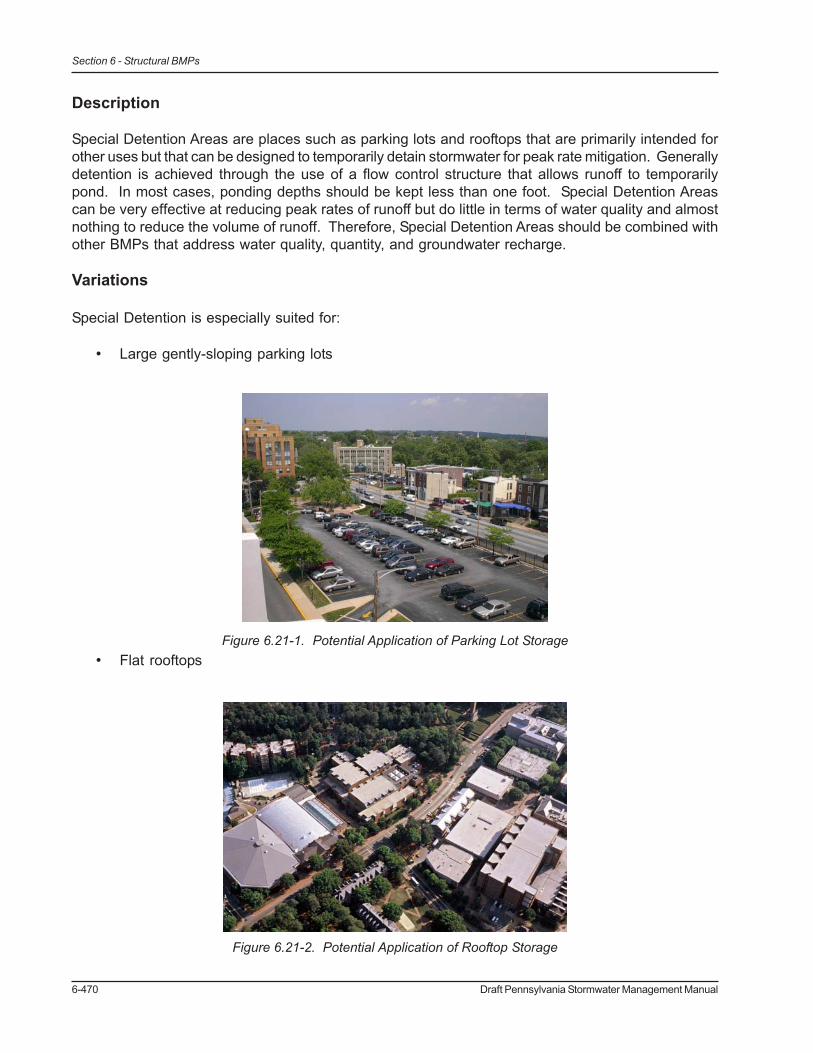
6-470 Draft Pennsylvania Stormwater Management Manual
Section 6 - Structural BMPs
Description
Special Detention Areas are places such as parking lots and rooftops that are primarily intended forother uses but that can be designed to temporarily detain stormwater for peak rate mitigation. Generallydetention is achieved through the use of a flow control structure that allows runoff to temporarilypond. In most cases, ponding depths should be kept less than one foot. Special Detention Areascan be very effective at reducing peak rates of runoff but do little in terms of water quality and almostnothing to reduce the volume of runoff. Therefore, Special Detention Areas should be combined withother BMPs that address water quality, quantity, and groundwater recharge.
Variations
Special Detention is especially suited for:
• Large gently-sloping parking lots
• Flat rooftopsFigure 6.21-1. Potential Application of Parking Lot Storage
Figure 6.21-2. Potential Application of Rooftop Storage

Draft Pennsylvania Stormwater Management Manual 6-471
Section 6 - Structural BMPs
• Recessed plazas
• Athletic fields
Applications
Detention areas can be created in parking lots in depressed areas or along curbs by controlling flowat stormwater inlets and/or using raised curbing. Rooftop runoff storage can be achieved by restrictingflow at scuppers, drains, parapet wall openings, etc. Recessed plazas and athletic fields can bedesigned with detention through the use of flow control structures and/or berms (for fields). SpecialDetention Areas can be used effectively to attenuate flows reaching other BMPs and thereby increasetheir performance; they can also be used to meet release rate requirements from Act 167 plans ormunicipal ordinances.
Figure 6.21-3. Potential Application of Plaza Storage
Figure 6.21-4. Potential Application of Athletic Field Storage

6-472 Draft Pennsylvania Stormwater Management Manual
Section 6 - Structural BMPs
Design Considerations
1. General
a. Emergency overflows should be designed to prevent excessive depths fromoccurring during extreme events or if the primary flow control structures areclogged. Emergency overflows must be designed to safely convey flowsdownstream.
b. Storage areas should be adequately sloped towards outlets to ensure completedrainage after storm events.
c. Flow control structures should be designed to discharge stored runoff in a timelymanner so that the primary use of the area can be restored.
2. Parking Lot Storage
a. Locate storage in areas so that ponding will not significantly disrupt typical trafficor pedestrian flow. Remote areas of large commercial parking lots, overflowparking areas, and other under-utilized parking areas are prime locations.
b. Minimize potential safety risks and property damage due to ponding. Detentionareas should be identified with signage or pavement markings or their use shouldbe restricted during storms.
c. Storage depths must be no greater than 1 foot.d. The area used for detention should be sloped towards the flow control structure at
a least 0.5% to ensure adequate drainage after storms. Slopes greater than 5%tend to be inefficient because storage volume is much lower for a given pondingdepth.
3. Rooftop Storage
a. The roof structure must be able to support the additional load created by pondedwater. Most roofs designed for snow load will be able to support runoff storage.
b. Ponding depths should generally be less than 6 inches and stored water shouldnot cause damage to any HVAC equipment on the roof.
c. The areas utilized for storage must have adequate waterproofing.d. Emergency overflows can be provided by openings in the parapet wall or by
additional drains.
Detailed Stormwater Functions
Volume Reduction Calculations
Special Detention Areas generally do not achieve significant volume reduction.
Peak Rate Mitigation Calculations
Peak rate of runoff is reduced in Special Detention Areas through the transient storage provided.See in Section 9 for Peak Rate Mitigation methodology.

Draft Pennsylvania Stormwater Management Manual 6-473
Section 6 - Structural BMPs
Water Quality Improvement
Although they may provide some quality improvement through settling, Special Detention Areas donot appreciably address water quality.
Construction Sequence
Not applicable.
Maintenance Issues
Special Detention Areas generally require little maintenance. Maintenance activities should includeinspection and cleaning of flow control structures, clearing debris/sediment from detention areas (asnecessary), and inspecting waterproofing in rooftop storage areas.
Cost Issues
Special Storage Areas can be a very economical means of reducing peak rates of runoff becausethey require little additional material and take up no additional space on a site.
Specifications
The following specifications are provided for information purposes only. These specifications includeinformation on acceptable materials for typical applications, but are by no means exclusive or limiting.The designer is responsible for developing detailed specifications for individual design projects inaccordance with the project conditions.
1. Flow Control Structures
a. Flow control structures shall be constructed of non-corrodible material.b. Structures shall be resistant to clogging by debris, sediment, floatables, plant
material, or ice.c. Materials shall comply with applicable specifications (PennDOT or AASHTO, latest
edition)
2. Waterproofing
a. Waterproofing shall prevent all water migration into the building.b. Waterproofing must comply with applicable state and local building codes.c. Waterproofing shall have an expected service life of at least 25 years.

6-474 Draft Pennsylvania Stormwater Management Manual
Section 6 - Structural BMPs
References
2001, Georgia Stormwater Management Manual; Volume Two: Technical Handbook
2003, Ontario Stormwater Management Planning & Design Manual
Iowa Statewide Urban Design Standards Manual
1992, Michigan - Index of Individual BMPs

Draft Pennsylvania Stormwater Management Manual 6-475
Section 6 - Structural BMPs
6.9 Protocols for Structural BMPs

6-476 Draft Pennsylvania Stormwater Management Manual
Section 6 - Structural BMPs

Draft Pennsylvania Stormwater Management Manual 6-477
Section 6 - Structural BMPs
6.9 Protocols for Structural BMPs
Protocol 1: Infiltration Systems Guidelines
Role of Infiltration BMPsThe phrase “infiltration BMPs” describes a wide range of stormwater management practices aimedat infiltrating some fraction of stormwater runoff from developed surfaces into the soil horizon andeventually into deeper groundwater. In this manual the major infiltration strategies are grouped intofour categories or types, based on construction and performance similarities:
• Surface Infiltration Basins• Subsurface Infiltration Beds• Bioretention Areas/Rain Gardens• Other BMPs that support infiltration (vegetated filter/buffer strips, level spreaders, and
vegetated swales)
Infiltration BMPs are one of the most beneficial approaches to stormwater management for a varietyof reasons including:
• Reduction of the peak rate of runoff• Reduction of the volume of runoff• Removal of a significant portion of the particulate-associated pollutants and some portion
of the solute pollutants.• Recharge of groundwater and maintenance of stream baseflow.
Quantitatively, infiltration BMPs replicate the natural hydrologic regime. During periods of rainfall,infiltration BMPs reduce the volume of runoff and help to mitigate potential flooding events. Duringperiods of reduced rainfall, this recharged water serves to provide baseflow to streams and maintainin stream water quality. Qualitatively, infiltration BMPs are known to remove nonpoint source pollutantsfrom runoff through a complex mix of physical, chemical, and biological removal processes. Infiltrationpromotes maintenance of the natural temperature regimes of stream systems (cooler in summer,warmer in winter), which can be critical to the aquatic ecology. Because of the ability of infiltrationBMPs to reduce the volume of runoff, there is also a corresponding reduction in erosive “bankfull”conditions and downstream erosion and channel morphology changes.
Infiltration BMPs are designed to infiltrate some portion of runoff during every storm event. Duringsmall storm events, a large percentage of the runoff may infiltrate, whereas during large storm events,the volume that infiltrates may only be a small portion of the total runoff. However, because most ofthe rainfall in Pennsylvania occurs in small (less than 1-inch) rainfalls, the annual benefits of aninfiltration system may be significant.
Purpose of Protocol 1 Infiltration Systems GuidelinesThe purpose of this protocol is to provide the designer with specific guidelines for the successfulconstruction and longterm performance of Infiltration BMPs. These guidelines fall into three categories:
1. Site conditions and constraints2. Design considerations3. Construction requirements

6-478 Draft Pennsylvania Stormwater Management Manual
Section 6 - Structural BMPs
All of these guidelines are important, and successful infiltration is dependent on careful considerationof site conditions, careful design, and careful construction.
1. SITE CONDITIONS and CONSTRAINTS
a) It is desirable to maintain at least a 2-foot clearance above the seasonally high watertable. This assures unimpeded permeability in the sub-soil, and allows sufficient distanceof water movement through the soil to assure adequate pollutant removal.
b) Maintain a minimum depth to bedrock of 2-feet to assure adequate pollutant removal.In special circumstances, filter media may be employed to remove pollutants if adequatesoil mantle does not exist.
c) It is desired that soils underlying infiltration devices should have infiltration ratesbetween 0.1 and 10 inches per hour, which in most development programs should notresult in an infiltration system which is excessively sized. Where soil permeability isextremely low, infiltration is possible but the surface area required may be large, and othervolume reduction methods may be required. Undisturbed Hydrologic Soil Groups B and Coften fall within this range and cover most of the state. Soils with rates in excess of 6.0inches per hour may require an additional soil buffer (such as an organic layer over the bedbottom) if the Cation Exchange Capacity (CEC) is less than 5. In carbonate soils,excessively rapid drainage may increase the risk of sinkhole formation, and somecompaction or additional soil may be appropriate.
d) Infiltration BMPs should be sited so that they present no threat to groundwater quality,at least 50 feet from individual water supply wells, and 100 feet from community ormunicipal water supply wells. Horizontal separation distances or buffers may also beappropriate from Special Geologic Features, such as fractures traces and faults, dependingon water supply sources.
e) Infiltration BMPs should be sited so that they present no threat to sub-surfacestructures, at least 20 feet downgradient or 100 feet upgradient from building basementfoundations, and 50 feet from septic system drainfields.
In general, soils of Hydrologic Soil Group D will not be suitable for infiltration. Similarly, areas offloodplains and areas of close proximity to wetlands and streams will not be suitable for infiltration.In developing areas that were previously used for agricultural purposes, the designer shouldconsider the past patterns of land use. Areas that were suitable for cultivation will likely besuitable for some level of infiltration. Areas that were left out of cultivation often indicate locationsthat are too wet or too rocky, and will likely not be suitable for infiltration.
2. DESIGN CONSIDERATIONS
a) Do Not Infiltrate in Compacted Fill. Infiltration in native soil without prior fill or disturbanceis preferred but not always possible. Areas that have experienced historic disturbance or fillare suitable for infiltration provided sufficient time has elapsed and the Soil Testingindicates the infiltration is feasible. In disturbed areas it may be necessary to infiltrate at adepth that is beneath soils that have previously been compacted by construction methodsor long periods of mowing, often 18-inches.

Draft Pennsylvania Stormwater Management Manual 6-479
Section 6 - Structural BMPs
b) A Level Infiltration Area (1% or less slope) is preferred. Bed bottoms should always begraded into the existing soil mantle, with terracing as required to construct flat structures.Sloped bottoms tend to pool and concentrate water in small areas, reducing the overall rateof infiltration and longevity of the BMP. Infiltration areas should be flat or nearly so.
c) The soil mantle should be preserved to the maximum extent possible, and excavationshould be minimized. Those soils that do not need to be disturbed for the building programshould be left undisturbed. Macropores provide the primary mechanism for watermovement in infiltration systems, and the extent of macropores often decreases with depth.Therefore, excessive excavation for the construction of infiltration systems is stronglydiscouraged.
d) Isolate “hot spot areas”. Site plans that include ‘hot spots’ need to be considered. ‘Hotspots’ are most often associated with some industrial uses and high traffic – gasolinestations, vehicle maintenance areas, and high intensity commercial uses (fast foodrestaurants, convenience stores, etc.). These “hot spots” are defined in the Section 3.3,Stormwater Standards for Special Areas. Infiltration may occur in areas of hot spotsprovided pretreatment is suitable to address concerns. Pretreatment requirements need tobe analyzed, especially for ‘hot spots’ and areas that produce high sediment loading.Pretreatment devices that operate effectively in conjunction with infiltration include grassswales, vegetated filter strips, settling chambers, oil/grit separators, constructed wetlands,and sediment sumps. Selection of pretreatment should be guided by the pollutants ofgreatest concern, site by site, depending upon the nature and extent of the landdevelopment under consideration. Selection of pretreatment techniques will varydepending upon whether the pollutants are of a particulate (sediment, phosphorus, metals,etc.) versus soluble (nitrogen and others) nature. Types of pretreatment (i.e., filters) shouldbe matched with the nature of the pollutants expected to be generated.
e) The Loading Ratio of impervious area to bed bottom area must be considered. One ofthe more common reasons for infiltration system failure is the design of a system thatattempts to infiltrate a substantial volume of water on a very small area. Infiltration systemswork best when the water is “spread out”. The Loading Ratio describes the ratio ofimperious drainage area to infiltration area, or the ratio of total drainage area to infiltrationarea. In general, the following Loading Ratios are recommended:
· A Loading Ratio of 5:1 relating impervious drainage area to infiltration area.· A Loading Ratio of 8:1 relating total drainage area to infiltration area.
f) The Hydraulic Head or Depth of Water should be limited. The total effective depth ofwater should generally not be greater than two feet to avoid compaction of the bed bottom.Often the water depth is limited by the Loading Ratio and Drawdown Time and is not anissue.
g) Drawdown Time must be considered. In general, infiltration BMPs should be designed sothat infiltration occurs within a 72-hour period in most situations.
h) All infiltration BMPs should be designed with a positive overflow that discharges excessvolume in a non-erosive manner, and allows for controlled discharge during extreme rainfallevents or frozen bed conditions. Infiltration BMPs should never be closed systemsdependent entirely upon infiltration in all situations.
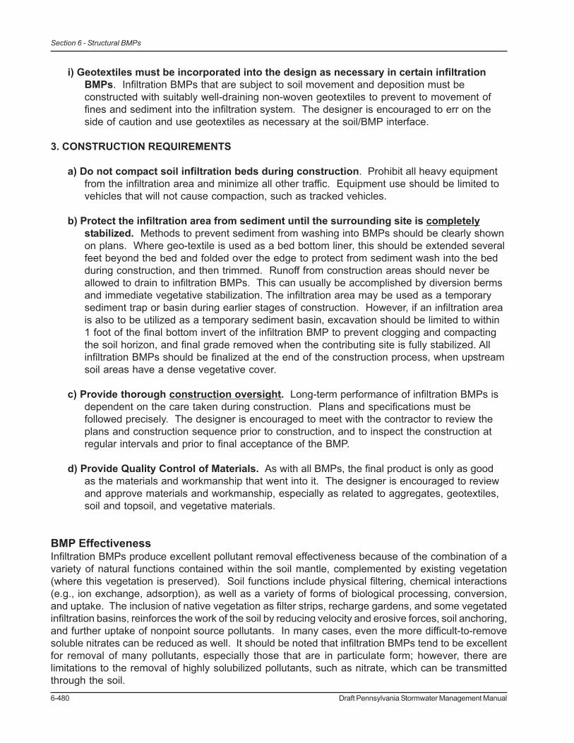
6-480 Draft Pennsylvania Stormwater Management Manual
Section 6 - Structural BMPs
i) Geotextiles must be incorporated into the design as necessary in certain infiltrationBMPs. Infiltration BMPs that are subject to soil movement and deposition must beconstructed with suitably well-draining non-woven geotextiles to prevent to movement offines and sediment into the infiltration system. The designer is encouraged to err on theside of caution and use geotextiles as necessary at the soil/BMP interface.
3. CONSTRUCTION REQUIREMENTS
a) Do not compact soil infiltration beds during construction. Prohibit all heavy equipmentfrom the infiltration area and minimize all other traffic. Equipment use should be limited tovehicles that will not cause compaction, such as tracked vehicles.
b) Protect the infiltration area from sediment until the surrounding site is completelystabilized. Methods to prevent sediment from washing into BMPs should be clearly shownon plans. Where geo-textile is used as a bed bottom liner, this should be extended severalfeet beyond the bed and folded over the edge to protect from sediment wash into the bedduring construction, and then trimmed. Runoff from construction areas should never beallowed to drain to infiltration BMPs. This can usually be accomplished by diversion bermsand immediate vegetative stabilization. The infiltration area may be used as a temporarysediment trap or basin during earlier stages of construction. However, if an infiltration areais also to be utilized as a temporary sediment basin, excavation should be limited to within1 foot of the final bottom invert of the infiltration BMP to prevent clogging and compactingthe soil horizon, and final grade removed when the contributing site is fully stabilized. Allinfiltration BMPs should be finalized at the end of the construction process, when upstreamsoil areas have a dense vegetative cover.
c) Provide thorough construction oversight. Long-term performance of infiltration BMPs isdependent on the care taken during construction. Plans and specifications must befollowed precisely. The designer is encouraged to meet with the contractor to review theplans and construction sequence prior to construction, and to inspect the construction atregular intervals and prior to final acceptance of the BMP.
d) Provide Quality Control of Materials. As with all BMPs, the final product is only as goodas the materials and workmanship that went into it. The designer is encouraged to reviewand approve materials and workmanship, especially as related to aggregates, geotextiles,soil and topsoil, and vegetative materials.
BMP EffectivenessInfiltration BMPs produce excellent pollutant removal effectiveness because of the combination of avariety of natural functions contained within the soil mantle, complemented by existing vegetation(where this vegetation is preserved). Soil functions include physical filtering, chemical interactions(e.g., ion exchange, adsorption), as well as a variety of forms of biological processing, conversion,and uptake. The inclusion of native vegetation as filter strips, recharge gardens, and some vegetatedinfiltration basins, reinforces the work of the soil by reducing velocity and erosive forces, soil anchoring,and further uptake of nonpoint source pollutants. In many cases, even the more difficult-to-removesoluble nitrates can be reduced as well. It should be noted that infiltration BMPs tend to be excellentfor removal of many pollutants, especially those that are in particulate form; however, there arelimitations to the removal of highly solubilized pollutants, such as nitrate, which can be transmittedthrough the soil.

Draft Pennsylvania Stormwater Management Manual 6-481
Section 6 - Structural BMPs
In addition to the removal of chemical pollutants, infiltration can address thermal pollution. Maintainingnatural temperatures in stream systems is recognized as an issue of increasing importance forprotection of overall stream ecology. Detention facilities tend to discharge heated runoff flows. Thereturn of runoff to the groundwater through use of infiltration BMPs guarantees that these waters willbe returned at natural groundwater temperatures, considerably cooler than ambient air in summerand warmer in winter, so that seasonal extreme fluctuations in stream water temperature are minimized.Fish, macroinvertebrates, and a variety of other biota will benefit as the result.
Although precise data on pollutant removal efficiencies is somewhat limited, infiltration BMPs havebeen shown to have excellent efficiencies for a wide range of pollutants. In fact, recent EPA guidancehas suggested that infiltration BMPs can be considered 100 percent effective at removing pollutantsfrom surface water for the fraction of water that infiltrates (EPA, 1999a). Other more conservativeremovals are reported in a variety of other sources. Table 5-1 displays average annual pollutantremoval efficiencies for infiltration BMPs that are designed for the 2-yr storm (3.1 inches / 24 hr.).BMPs that treat less than the 2-year storm may have lower efficiencies than those reported in Table5-1 because less runoff is allowed to infiltrate.
Fate of Infiltrated ContaminantsThe protection of groundwater quality is of utmost importance in any PA watershed. The potential tocontaminate groundwater by infiltrating stormwater in properly designed and constructed BMPs withproper pretreatment is low, if come common sense rules are followed, as discussed above. Numerousstudies have shown that stormwater infiltration BMPs have a minor risk of contaminating eithergroundwater or soil. Perhaps the most comprehensive research was conducted by the U.S.Environmental Protection Agency, summarized in “Potential Groundwater Contamination fromIntentional and Nonintentional Stormwater Infiltration” (Pitt et al., 1994). A table is presented whichidentifies the potential of pollutants to contaminate groundwater as either low, low/moderate, moderate,or high. Of the 25 physical pollutants listed, only one has a “high” potential (chloride), and only twohave even “moderate” potential (fluoranthene and pyrene) for polluting groundwater through the useof shallow infiltration systems with some sediment pretreatment. Pentachlorophenol, cadmium, zinc,chromium, lead, and all the pesticides listed are classified as having a “low” contamination potential.Even nitrate which is soluble and mobile (discussed further below) is only given a “low/moderate”potential.
Legret et al. (1999) simulated the long term effects of heavy metals in infiltrating stormwater andconcluded that the “long-term pollution risks for both soil and groundwater are low,” and “metals aregenerally well retained in the upper layers of the soil (0-20 cm) [0-8 inches]…” Barraud et al. (1999)studied a thirty year-old infiltration BMP and found that both metal and hydrocarbon concentrationsin the soil under the infiltration device decreased rapidly with depth “to a low level after a few decimetersdown [3 decimeters = 1 foot]…” A study concerning the infiltration of highway runoff (Dierkes andGeiger, 1999) found that polycyclic aromatic hydrocarbons (PAH) were effectively removed in theupper 4 inches of the soil and that runoff that had passed through 14 inches of soil met drinking waterstandards for cadmium, zinc, and copper. This extremely high pollutant removal and retention capacityof soils is the result of a multitude of natural processes including physical filtering, ion exchange,adsorption, biological processing, conversion, and uptake.
Several studies have also found that porous pavement and stone-filled subsurface infiltration bedscan significantly reduce the pollutant concentrations (especially hydrocarbons and heavy metals) ofstormwater runoff before it even reaches the underlying soil due to adsorption, filtering, sedimentation,and bio-degradation by a diverse microbial community in the pavement and infiltration beds (Legret

6-482 Draft Pennsylvania Stormwater Management Manual
Section 6 - Structural BMPs
and Colandini, 1999; Balades et al., 1995; Swisher, 2002; Newman et al., 2002; and Pratt et al.,1999).
Common Causes of Infiltration BMP “Failures”The concept of failure is simple – a design no longer provides the benefit or performance anticipated.With respect to stormwater infiltration BMPs, the term requires some qualification, since the netresult of “failure” may be a reduction in the volume of runoff anticipated or the discharge of stormwaterwith excessive levels of some pollutants. Where the system includes built structures, such as porouspavements, failure may include loss of structural integrity for the wearing surface, whereas the infiltrationfunction may continue uncompromised. For infiltration systems with vegetated surfaces, such asplay fields or rain gardens, failure may include the inability to support surface vegetation, caused bytoo much or too little water.
The primary causes of reduced performance appear to be:a) Poor construction techniques, especially soil compaction/smearing, which results in
significantly reduced infiltration rates.b) A lack of site soil stabilization prior to the BMP receiving runoff, which greatly increases the
potential for sediment clogging from contiguous land surfaces.c) Inadequate pretreatment, especially of sediment-laden runoff, which can cause a gradual
reduction of infiltration rates.d) Lack of proper maintenance (erosion repair, re-vegetation, removal of detritus, catch basin
cleaning, vacuuming of pervious pavement, etc.), which can reduce the longevity ofinfiltration BMPs.
Infiltration systems should always be designed such that failure of the infiltration component doesnot compromise the peak rate attenuation capability of the BMP. Because the rate of design infiltrationis usually extremely small in comparison to the peak flow rates during large storm events, this isusually not an issue. Because infiltration BMPs are designed to infiltrate small, frequent storms, theloss or reduction of this capability does not usually significantly impact the storage and peak ratemitigation of the BMP during extreme events.
Consideration of Infiltration Rate in Design and Modeling ApplicationFor the purposes of site suitability, areas with tested soil infiltration rates as low as 0.1 inches perhour may be used for infiltration BMPs. However, in the design of these BMPs and the sizing of theBMP, the designer should incorporate a safety factor. For tested infiltration rates that are less than1.0 inches per hour as determined by percolation tests, the designer should incorporate a safetyfactor of two in sizing and designing the BMP. Therefore a measured infiltration rate of 0.5 inches perhour should be considered as a rate of 0.25 inches per hour in design.
If several percolation tests have been conducted, an average rate should be calculated and a safetyfactor applied as appropriate.
As discussed in Section 9 of this Manual, infiltration systems can be modeled similarly to traditionaldetention basins. The marked difference with modeling infiltration systems is the inclusion of theinfiltration rate, which can be considered as another outlet. For modeling purposes, it is convenientto develop infiltration rates that vary with elevation for inclusion in the Stage-Storage-Discharge table.The following equation may be used to relate infiltration rate to head:

Draft Pennsylvania Stormwater Management Manual 6-483
Section 6 - Structural BMPs
I = fcA(1.5heff+1)(1/43200)
where:I = infiltration flow rate at respective storage depth, cubic feet per secondheff = storage depth - average percolation testing depth (typically 6 to 8 inches; when storage depthis less than heff, consider heff equal to zero), feetA = bed bottom area, square feet (side slopes are generally not considered in calculation to beconservative)fc = minimum infiltration rate, inches per hour (reduced by safety factor)

6-484 Draft Pennsylvania Stormwater Management Manual
Section 6 - Structural BMPs
References
Balades et al., 1995.
Barraud et al. 1999.
Dierkes and Geiger, 1999.
EPA, 1999a.
Legret and Colandini, 1999.
Legret et al. 1999.
Newman et al., 2002.
Pitt et al., 1994. “Potential Groundwater Contamination from Intentional and NonintentionalStormwater Infiltration”
Pratt et al., 1999.
Swisher, 2002.
Draft Pennsylvania Stormwater Management Manual 6-485
Section 6 - Structural BMPs
Protocol 2. Soil Evaluation and Investigation for Infiltration BMP’s
Purpose of this ProtocolThe Soil Evaluation and Testing for Infiltration BMP’s Protocol is a critical component of the design ofinfiltration BMP’s and is intended to be used in conjunction with another protocol, Guidelines forInfiltration Systems. Generally, the purpose of the Guidelines for Infiltration Systems is to provide amethodology for the stormwater designer to determine if infiltration BMP’s are feasible at a site todesign those systems properly. The purpose of the Soil Evaluation and Investigation Protocol is toobtain the required data for infiltration BMP design. This process will also assist the designer in theappropriate selection and location of infiltration BMP’s at a site.
The Guidelines for Infiltration Systems includes a general Site Evaluation process (also discussed inSection 4) intended to assist the designer in determining the appropriate location for BMP’s, includingInfiltration BMP’s. This initial site evaluation includes the following steps:
1. Identify soil types and locations2. Identify site conditions that affect Infiltration BMP design3. Identify areas suitable for infiltration BMP’s4. Identify areas not suitable for Infiltration BMP’s
Based on the initial evaluation of areas that may be suitable for infiltration, detailed testing can thenbe performed. This detailed testing includes the following steps:
1. Conduct Soil Investigation Tests (Deep Hole Tests)2. Conduct Soil Infiltration Rate Tests
All Soil Evaluation and Infiltration Investigation shall be performed under the supervision of aprofessional Soils Scientist, Engineer, or Geologist licensed in the State of Pennsylvania.
Designers are encouraged to conduct Soil Evaluation and Investigation early in the site planning anddesign process. Full build-out of site areas otherwise deemed to be suitable for infiltration does notprovide an exemption or waiver from volume control, which can be provided through cost effectiveinfiltration BMP’s. Testing site soils and understanding how the site is functioning is fundamentallyimportant early on in the site planning process, and municipalities are encouraged to require completionof all testing prior to Preliminary Plan approval.
The Site Planning and Design Process: Site Evaluation for Infiltration BMP’s andTheir Location
As part of the site planning and design process, existing conditions at the site should be inventoriedand evaluated including, but not limited to:
• Existing soils and USDA Hydrologic Soil Group classifications• Existing geology, including the location of any dikes, contacts, or other features of note• Existing streams (perennial and intermittent, including intermittent swales), water bodies,
wetlands, hydric soils, floodplains and alluvial soils, stream classifications, headwaters and1st order streams
• Existing topography, slope, drainage patterns
6-486 Draft Pennsylvania Stormwater Management Manual
Section 6 - Structural BMPs
• The proposed layout plan for development• The location of all existing and proposed water supply sources and wells.• The location of all existing and proposed on-site wastewater systems.• The location of any other features of note such as utility right-of-ways.
The designer should research existing soil conditions at the project site prior to testing, including soilformation, series associations, soils descriptions, Hydrologic Soil Group classification, and so forth.Especially important are limiting factors such as depth to bedrock and depth to seasonal high watertable, as well as any published information relating to the rated permeability of the soil type, lackingany actual soil testing results from the site itself. Any additional data available, such as structuralboring data, should also be considered. All available information should be compiled and overlaid onthe site plan, with feasibility constraints clearly marked. As the result of this process, the designershall determine the preliminary location and type of infiltration BMP’s for the proposed developmentplan, assuming feasibility. The approximate location of these infiltration BMP’s shall be located onthe Proposed Development Plan. The approximate locations for infiltration BMP’s shall serve as thebasis for the location and number of tests to be performed, as set forth below.
Types of Soil Investigation
All soils tests shall include both Test Pits (Deep Holes) and Infiltration Rate tests. The use of Test Pitsis strongly encouraged as a Test Pit allows the Designer to visually observe the soil horizons andoverall soil conditions both horizontally and vertically in that general area of the site. An extensivenumber of Test Pit observations can be made across a site at a relatively low cost and in a short timeperiod. This provides the designer with a valuable understanding of site conditions. The use of soilborings as a substitute for Test Pits is discouraged, as the available area for visual observation isnarrowly limited.
1. Test Pits (Deep Holes)A Deep Hole shall consist of a backhoe-excavated trench, 2-1/2 to 3 feet wide, to a depth of between72 inches and 90 inches, or until bedrock is encountered. The trench should be benched at a depthof 2-3 feet for access and/or multiple percolation tests. Soil horizons are to be identified and describedin depth (in inches) from the surface.
At each Deep Hole, the following conditions shall be noted:
• Upper and Lower boundary of Horizon, soil textural class, soil texture modifier (ifapplicable), estimated type, percent and size of coarse fragments, soil color, color patterns(mottling), pores, roots, soil and/or rock structure, consistency.
• Name, date, elevation, location, test number, equipment used, depth to water, depth tobedrock, geology, soil map unit, land use, additional comments.
At the Engineer’s discretion, soil samples may be collected at various horizons for additional analysis.Following testing, the deep holes are to be refilled with the original soil and the surface replaced withthe original topsoil.
The Form shown in Figure 6.8-1 may be used for documentation of each Deep Hole.

Draft Pennsylvania Stormwater Management Manual 6-487
Section 6 - Structural BMPs
It is important that the Deep Hole provide information related to conditions at the bottom of theproposed Infiltration BMP. If the BMP depth will be greater than 90 inches below existing grade,deeper excavation will be required. The Designer is cautioned regarding the proposal of systemsthat are significantly lower than the existing topography, as the suitability for infiltration is likely todecrease. The Designer is encouraged to consider reducing grading and earthwork as needed toreduce site disturbance and provide greater opportunity for stormwater management.
Figure 2 Deep Hole Test
Figure 1 Deep Hole Test Indicating Multiple Horizons.

6-488 Draft Pennsylvania Stormwater Management Manual
Section 6 - Structural BMPs
2. Infiltration Tests
There are several techniques for determining the infiltration capacity of a soil. Fields tests are stronglyencouraged, while laboratory tests are strongly discouraged, as laboratory testing cannot adequatelyevaluate the macropore system in a soil. Macropores occur primarily in the upper soil horizons andare formed by plant roots (both living and decaying), soil fauna such as insects, the weatheringprocesses caused by the movement of water, the freeze-thaw cycle, soil shrinkage due to desiccationof clays, chemical processes, and other mechanisms. These macropores provide an importantmechanism for infiltration prior to development, extending vertically and horizontally for considerabledistances. It is the intent of good engineering and design practice to maintain these macropores inthe installation of Infiltration BMPs.
When a sample is taken to the laboratory and evaluated for hydraulic conductivity based on ahomogeneous sample, the macropore system is compromised. Darcy’s Law is based on theassumption of a homogeneous soil sample and cannot be used to adequately represent the movementof water through macropores. While macropores may represent a small percentage of total porosity,they allow for significant movement of water through natural soil systems. For this reason, infiltrationtests should be conducted in the field.
Infiltration tests may consist of:
• Percolation tests (such as for on-site wastewater systems and Pa Chapter 73 (ref))• Infiltrometer or Double-ring Infiltrometer tests• ASTM 2003 Volume 4.08, Soil and Rock (I): Designation D 3385-03, Standard Test Method
for Infiltration Rate of Soils in Field Using a Double-Ring Infiltrometer.• ASTM 2002 Volume 4.09, Soil and Rock (II): Designation D 5093-90, Standard Test Method
for Field Measurement of Infiltration Rate Using a Double-Ring Infiltrometer with a Sealed-Inner Ring.
There are differences between the methods. An Infiltrometer test measures the movement of waterthrough the bottom of the test area, whereas a percolation test allows water movement through boththe bottom and sides of the test area. For this reason, infiltrometer tests are considered to be a moreconservative, and possibly more accurate, estimate of potential infiltration capability.
The limitation of Infiltrometer tests is that the required equipment can be costly, and an infiltrometeris required for every test location. For a site with multiple test locations, such as a residentialdevelopment considering on-lot infiltration, the testing requirements can be extensive. For this reasonthe continued use of percolation tests should be considered acceptable. Multiple percolation testscan be performed to provide a broader perspective of site soil conditions. The rate of infiltration mayalso be affected by the head of water. However, for the methodologies described herein, the effectsare negligible.
Number and Location of Tests Required
Based upon the proposed location of BMPs, Soil Evaluation and Investigation shall be conducted.All soils tests shall include both Test Pits (Deep Holes) and Infiltration Rate tests. Deep Hole Testsshall be required as follows:
• For single-family residential subdivisions, one test pit per lot is required at proposed BMP

Draft Pennsylvania Stormwater Management Manual 6-489
Section 6 - Structural BMPs
location.• For large infiltration areas (commercial, institutional, industrial, and other proposed land
uses), multiple test pits should be evenly distributed at the rate of four (4) to six (6) testsper acre of BMP area.
• Additional tests should be conducted if local conditions indicate significant variability insoils, geology, topography, etc.
Infiltration Tests are required at the rate of two per Deep Hole. The Designer is encouraged toperform at least one test at the proposed bed bottom elevation (if known). Tests may be performedin different soil horizons to provide the Designer with additional information.
Infiltration tests should not be conducted in the rain or within 24 hours of significant rainfall events(>0.5 inches).
Background Materials/Actions Needed for Soils Tests
1. PA OneCall 1-800-242-1776 or www.paonecall.org
Soil investigators are required to contact PA-OneCall to have the existing utilities marked in proposedtesting locations at least 3 business days prior to digging.
Below is a list of questions you will be asked when you call (blue = required questions). The locationof existing underground utilities may affect the proposed test pits locations. Prior to field-testing,have alternative test pit sites marked on the plan in the event that underground utilities lie within inyour test pit locations.
• What is your telephone number with the area code first?• Your name?• If you have not called in before, you will be asked for company information.• Who is the contact person at the dig site? Their phone number?• What is the best time to call the contact person?• In what county will the work be done?• In what city, twp or borough will the work be done?• In Erie, Pgh, Allentown or Phila, What is the ward #.• What is the starting address number?• What is the ending address number?• What is the street name for the work site?• What is the nearest intersecting street name?• Do you have any other site-specific location information?• Will the proposed dig site be marked in white?• If a state road, do you have a PennDOT permit number?• Latitude?• Longitude?• What type of work will be done?• Approximately how deep will you be digging?• What type of equipment will be used?

6-490 Draft Pennsylvania Stormwater Management Manual
Section 6 - Structural BMPs
• What are the dimensions (width, length, diameter)?• Will the work take place in the street?• Will the work take place on the sidewalk?• Will the work take place on public property?• Will the work take place on private property?• Where on private property? (use drop down box)• Private prop owner or company name working for?• Work date? (utilities need 3 working days notice) *• What is the time you will begin the work?• Is there anything else you would like to add?
2. Safety
Adherence should be paid to all applicable OSHA regulations and local guidelines related to earthworkand excavation. At no time shall a deep hole be left unattended unless secured and marked. Noperson shall enter a deep hole at a depth greater than hip level.
• The deep hole is not to be accessed if soil conditions are unsuitable for safe entry, or if siteconstraints preclude entry.
• If it is necessary to leave the deep hole unfilled and unattended for any reason, plywoodsheets of 1/4 inch thickness shall be secured over the opening, and the hole shall beclearly marked and secured with caution tape at all sides.
3. Equipment
The following is a list of equipment that is commonly used in Infiltration Testing:
• Backhoe• Post hole digger or auger, if required• Clean water source (preferably on site; approximately 5-10 gallons per deep hole)• 5-gallon container(s)• Hard-hat, caution tape, cones, etc., and other required safety elements• Test Log sheets• Measuring tape stick• Knife blade or sharp-pointed instrument (for soil scarification)• Coarse sand or fine gravel• Object for fixed-reference point during measurement (nail, toothpick, etc.)• Stopwatch for time measurement• Infiltrometer, if desired
Methodology
This percolation test methodology largely follows the Pennsylvania Department of EnvironmentalProtection (PADEP) criteria for on-site sewage investigation of soils (as described in Chapter 73 ofthe Pennsylvania Code).
For each test pit excavated as part of the infiltration testing, a minimum of two infiltration tests shallbe done. At least one test shall be located within the expected horizon of the bottom of the proposed

Draft Pennsylvania Stormwater Management Manual 6-491
Section 6 - Structural BMPs
infiltration BMP. The Designer should conduct infiltration tests at alternate depths if the test pits/auger holes indicate that the soils are more suitable at a different depth (i.e., if a clay horizon isidentified and more suitable soils are located beneath the horizon, an infiltration test should beperformed in the suitable horizon).
1. Deep Hole Execution and Investigation• Locations for deep hole investigations shall be determined by the Designer based on site
conditions and the proposed development plan.• The deep hole shall consist of a backhoe-excavated trench, 2-1/2 to 3 feet wide, to a depth
of between 72 inches and 90 inches, or until bedrock is encountered.• The trench should be benched at a depth of 2-3 feet for access and/or multiple percolation
tests.• Soil horizons are to be identified and described in depth (in inches) from the surface.• Depth to water table or perched water table shall be noted, as well as any indications of
high water table (i.e., mottled soils).• Depth to bedrock or weathered bedrock shall be noted if encountered.• The approximate elevation of the surface shall be recorded, if possible.• The deep hole is not to be accessed if soil conditions are unsuitable for safe entry, or if site
constraints preclude entry.• Deep holes might be located more frequently if site investigation indicates changes in soil
types, geology, water table levels, bedrock bedding, etc.• Following percolation tests, the deep holes are to be refilled with the original soil and the
surface replaced with the original topsoil.• If it is necessary to leave the deep hole unfilled and unattended for any reason, plywood
sheets of 1/4 inch thickness shall be secured over the opening, and the hole shall beclearly marked and secured with caution tape at all sides.
• At the Designer’s discretion, soil samples may be collected at various horizons foradditional analysis.
Figure 3 Excavation of deep hole by backhoe
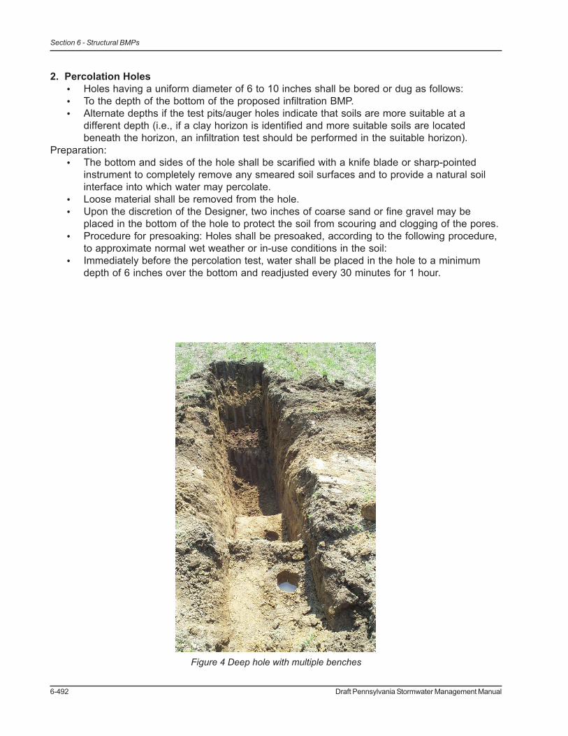
6-492 Draft Pennsylvania Stormwater Management Manual
Section 6 - Structural BMPs
2. Percolation Holes• Holes having a uniform diameter of 6 to 10 inches shall be bored or dug as follows:• To the depth of the bottom of the proposed infiltration BMP.• Alternate depths if the test pits/auger holes indicate that soils are more suitable at a
different depth (i.e., if a clay horizon is identified and more suitable soils are locatedbeneath the horizon, an infiltration test should be performed in the suitable horizon).
Preparation:• The bottom and sides of the hole shall be scarified with a knife blade or sharp-pointed
instrument to completely remove any smeared soil surfaces and to provide a natural soilinterface into which water may percolate.
• Loose material shall be removed from the hole.• Upon the discretion of the Designer, two inches of coarse sand or fine gravel may be
placed in the bottom of the hole to protect the soil from scouring and clogging of the pores.• Procedure for presoaking: Holes shall be presoaked, according to the following procedure,
to approximate normal wet weather or in-use conditions in the soil:• Immediately before the percolation test, water shall be placed in the hole to a minimum
depth of 6 inches over the bottom and readjusted every 30 minutes for 1 hour.
Figure 4 Deep hole with multiple benches
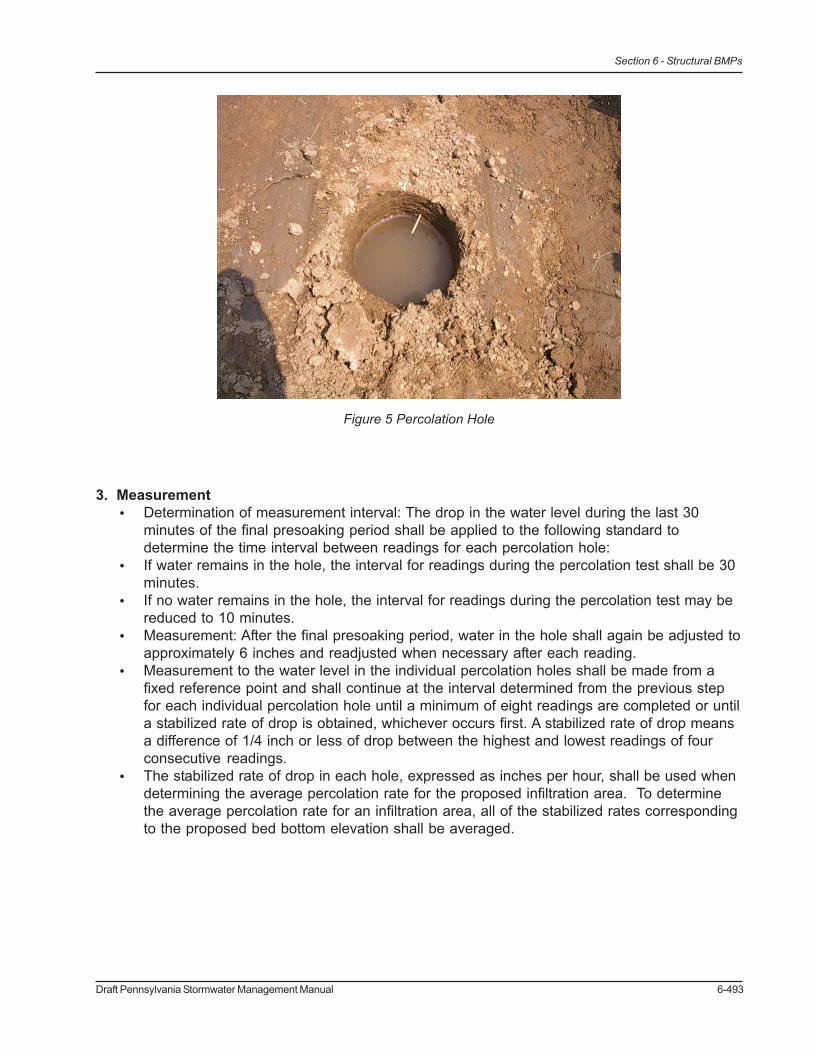
Draft Pennsylvania Stormwater Management Manual 6-493
Section 6 - Structural BMPs
3. Measurement• Determination of measurement interval: The drop in the water level during the last 30
minutes of the final presoaking period shall be applied to the following standard todetermine the time interval between readings for each percolation hole:
• If water remains in the hole, the interval for readings during the percolation test shall be 30minutes.
• If no water remains in the hole, the interval for readings during the percolation test may bereduced to 10 minutes.
• Measurement: After the final presoaking period, water in the hole shall again be adjusted toapproximately 6 inches and readjusted when necessary after each reading.
• Measurement to the water level in the individual percolation holes shall be made from afixed reference point and shall continue at the interval determined from the previous stepfor each individual percolation hole until a minimum of eight readings are completed or untila stabilized rate of drop is obtained, whichever occurs first. A stabilized rate of drop meansa difference of 1/4 inch or less of drop between the highest and lowest readings of fourconsecutive readings.
• The stabilized rate of drop in each hole, expressed as inches per hour, shall be used whendetermining the average percolation rate for the proposed infiltration area. To determinethe average percolation rate for an infiltration area, all of the stabilized rates correspondingto the proposed bed bottom elevation shall be averaged.
Figure 5 Percolation Hole
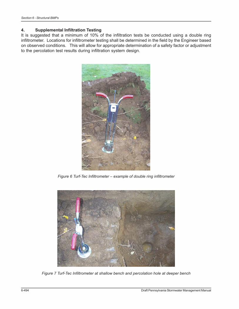
6-494 Draft Pennsylvania Stormwater Management Manual
Section 6 - Structural BMPs
4. Supplemental Infiltration TestingIt is suggested that a minimum of 10% of the infiltration tests be conducted using a double ringinfiltrometer. Locations for infiltrometer testing shall be determined in the field by the Engineer basedon observed conditions. This will allow for appropriate determination of a safety factor or adjustmentto the percolation test results during infiltration system design.
Figure 6 Turf-Tec Infiltrometer – example of double ring infiltrometer
Figure 7 Turf-Tec Infiltrometer at shallow bench and percolation hole at deeper bench