runtime precoding: enabling multipoint transmission in lte ... · pdf filetransmission in...
TRANSCRIPT

Received April 27, 2015, accepted May 13, 2015, date of publication June 1, 2015, date of current version June 9, 2015.
Digital Object Identifier 10.1109/ACCESS.2015.2437903
Runtime Precoding: Enabling MultipointTransmission in LTE-AdvancedSystem-Level SimulationsMARTIN TARANETZ, (Student Member, IEEE), THOMAS BLAZEK, THOMAS KROPFREITER,MARTIN KLAUS MÜLLER, (Student Member, IEEE), STEFAN SCHWARZ, (Member, IEEE),AND MARKUS RUPP, (Fellow, IEEE)Institute of Telecommunications, Vienna University of Technology, Vienna 1040, Austria
Corresponding author: M. Taranetz ([email protected])
This work has been funded by the Christian Doppler Laboratory for Wireless Technologies for Sustainable Mobility, the A1 TelekomAustria AG, and the KATHREIN-Werke KG. The financial support by the Federal Ministry of Economy, Family and Youth and theNational Foundation for Research, Technology and Development is gratefully acknowledged. The authors would like to thank theTU Wien for funding the publication fees.
ABSTRACT System-level simulations have become an indispensable tool for predicting the behavior ofwireless cellular systems. As exact link-level modeling is unfeasible due to its huge complexity, mathematicalabstraction is required to obtain equivalent results by less complexity. A particular problem in suchapproaches is the modeling of multiple coherent transmissions. Those arise in multiple-input-multiple-output transmissions at every base station but nowadays so-called coordinatedmultipoint (CoMP) techniqueshave become very popular, allowing to allocate two or more spatially separated transmission points. Also,multimedia broadcast single frequency networks (MBSFNs) have been introduced recently in long-termevolution (LTE), which enables efficient broadcasting transmission suitable for spreading information thathas a high user demand as well as simultaneously sending updates to a large number of devices. This paperintroduces the concept of runtime-precoding, which allows to accurately abstract many coherent transmissionschemes while keeping additional complexity at a minimum.We explain its implementation and advantages.For validation, we incorporate the runtime-precoding functionality into the Vienna LTE-A downlink system-level simulator, which is an open source tool, freely available under an academic noncommercial use license.We measure simulation run times and compare them against the legacy approach as well as link-levelsimulations. Furthermore, we present multiple application examples in the context of intrasite and intersiteCoMP for train communications and MBSFN.
INDEX TERMS Link abstraction, link quality model, runtime-precoding, 3GPP, LTE-A, Vienna LTE-Adownlink system level simulator, MIESM, Vienna LTE-A downlink link level simulator, LTE transmissionmodes, coordinated multipoint, multimedia broadcast single frequency networks, high-user mobility.
I. INTRODUCTION3gpp LTE-Advanced (LTE-A) is a key technology to meetthe requirements of fourth generation mobile communicationsystems (4G), as specified by the ITU-R [1], [2]. Today, itslimits are continuously pushed by academia, industry andstandardization bodies. Typically, the potential performanceof novel contributions is evaluated by extensive simulationsunder realistic conditions before gaining acceptance. To sig-nificantly reduce the complexity of such process, evaluationsare often separated into two stages or levels of abstraction,referred to as link level and system level, respectively [3].Link level simulations are applied for assessing the
performance of the physical layer as well as those higherlayer aspects that are directly related to the radio interface.
Typically, only a single link is evaluated, including featuressuch as synchronization, modulation and coding, channelfading, channel estimation and multi-antenna processing. It isby far too complex to simulate a substantial number of suchlinks.
The focus of the present work is on system level, where per-formance evaluation requires to encompass a large number ofnetwork elements and upscales the number of interconnectinglinks. In this case, the main interest lies in network-relatedissues such as resource allocation, mobility management andnetwork planning. Hence, computational complexity needsto be decreased substantially in order to make the problemfeasible. A widely accepted solution is the application of linkabstraction models [3] that specify the interaction between
VOLUME 3, 20152169-3536 2015 IEEE. Translations and content mining are permitted for academic research only.
Personal use is also permitted, but republication/redistribution requires IEEE permission.See http://www.ieee.org/publications_standards/publications/rights/index.html for more information.
725

M. Taranetz et al.: Enabling Multipoint Transmission in LTE-Advanced System-Level Simulations
link- and system level simulators and are further detailedin Section II. This structure is also expected to persist insimulation tools for the fifth generation of wireless cellularnetworks (5G) [4].
A. SURVEY ON EXISTING SIMULATION TOOLSThere are several ways to categorize existing system-levelsimulation tools. First, we may distinguish betweensimulators, which are implemented as ‘modules’ of alarger suite, and those, which are specifically designedfor LTE-A [5]. Examples for the former include theRiverbed SteelCentral NetModeler (formerly OPNETModeler Suite) [6], OMNeT++ [7], IT++ [8], ns-2 [9], [10],GNS3 [11], openWNS [12] and Hurricane II [13]. The maindrawback of these solutions is their low level of detail, henceleaving most implementation work to the user. Consequently,results often lack accuracy and verification. On the otherhand, technology-specific simulators are mainly developedby network operators and vendors, and are typically notintended for commercial distribution [5], [14]–[16]. Suchtools yield a broad range of possibilities for parametercalibration and statistical evaluation. Thus, they are keyinstruments for the standardization process and the develop-ment of new technologies.
While these two classes of simulators largely vary incomplexity, scalability and usability, probably the mostrelevant difference for scientific research is their accessibility.The authors strongly believe that open access is a key pre-requisite for reproducible simulation studies. The short listof openly available, technology-specific approaches includesLTE-Sim [17], the tool presented in [16] and the ViennaLTE-A downlink system level simulator. While the firstlacks of detailed Multiple-Input-Multiple-Output (MIMO)modeling, the second provides a rather limited set of features.In this work, we employ the Vienna LTE-A downlink systemlevel simulator [18] (latest version: v1.8 r1375), subsequentlyreferred to as Vienna LTE-A simulator, which is brieflyintroduced in the following.
B. THE VIENNA LTE-A DOWNLINK SYSTEMLEVEL SIMULATORThe Vienna LTE-A simulator is implemented in object-oriented MATLAB1 and is made openly available for down-load under an academic, non-commercial use license. Its richset of features and easy adaptability has led to numerouspublications from researchers all over the globe, includingstudies on energy-efficient cell-coordination schemes [20],handover algorithms in self-optimizing networks [21], andresource allocation techniques for femtocell networks [22] aswell as for machine-to-machine communication [23]. On topof that, the open accessibility warrants the reproducibility ofthese contributions. Today (May 2015), the simulator countsmore than 30 000 downloads and undergoes permanentpeer-review from a substantially large online community.
1For further information, see [19].
With some 100 000 lines of code, employing a large forumwith active users is the only method to guarantee its quality.For a comprehensive description, the interested reader isreferred to [24].
C. CONTRIBUTIONS AND ORGANIZATIONThis work is organized as follows. Section II briefly summa-rizes concepts for LTE-A physical layer modeling on systemlevel. The centerpiece of this contribution is the presenta-tion of a new runtime-precoding concept in Section III. Itsinnovation for openly available system level simulation toolslies in enabling the evaluation of scenarios where signals arecoherently transmitted from multiple spatially separatedtransmission points while not compromising the complex-ity reduction as achieved by well established link abstrac-tion models. For verifying the efficiency of our solution,we extend the link quality model of the Vienna LTE-Asimulator by a runtime-precoding feature. We comparesimulation run times as obtained with the enhanced- andthe legacy model as well as with link level simulations.Section IV presents two example applications, showingthe efficiency of intra- and inter-site Coordinated Multi-point (CoMP) schemes in high-speed train scenarios, and theimplementation of eNodeB-coordinating entities in Multime-dia Broadcast Single Frequency Networks (MBSFNs). Theirinvestigation represent a novelty in the field of open-sourceLTE-A simulators, since both only became feasible withthe proposed runtime-precoding concept. Section V con-cludes the work and outlines directions for future enhance-ments. The simulation assumptions throughout the paper arelargely based on recommendations from 3GPP [25]–[27]and ITU-R [28], respectively. The source files for repro-ducing the results are openly available for download on ourwebsite www.nt.tuwien.ac.at/ltesimulator. Note that the pro-posed runtime-precoding concept is applicable to any systemlevel simulation tool that employs the well accepted separa-tion between link quality- and link performance model, asexplained in Section II. Thus, the Vienna LTE-A simulatoris just one out of many possible tools, which has been chosento demonstrate the capabilities of the method.
II. PHYSICAL LAYER MODELINGThis section provides a brief introduction tomodeling concepts of the physical layer of LTE-Aon system level. The LTE-A PHY procedures canconceptually be described as a Bit-Interleaved Coded
FIGURE 1. Separation of an LTE link into link quality- and linkperformance model. The link can equivalently be described as anLTE BICM transmitter-receiver chain [24].
726 VOLUME 3, 2015

M. Taranetz et al.: Enabling Multipoint Transmission in LTE-Advanced System-Level Simulations
Modulation (BICM)-system [24], as shown in Figure 1.It comprises a transmitter including channel coder,bit interleaver and modulator (M). In LTE-A, codingand interleaving is achieved by a turbo-coder in combina-tion with rate matching. The symbol mapping employs 4-,16- and 64-QAM with Gray mapping, respectively. Signalpropagation over an NRx×NTx MIMO channel is commonlymodeled by slowly-varying, position-dependent macro-scalefading L0, small-scale fadingH0 and Additional White Gaus-sian Noise (AWGN). The matrix representation follows fromthe assumption that the cyclic prefix exceeds the channellength, hence omitting inter-symbol interference. The chan-nel coefficients are typically calculated from a power-delayprofile or a ray-based spatial channel model, such as theWinner model [29] or 3GPP’s 3D model [30]. The receiverencompasses an equalizer filter and a demodulator (M−1) aswell as a turbo decoder, which provides de-interleaving andchannel decoding.2
The objective of the link abstraction model is to predictthe performance of the presented LTE-A link, given a param-eterization of the inputs. For simplification, the model can bedivided into a link quality- and a link performance model, asindicated in Figure 1. The link quality model measures thequality of the received signal after equalization.3 The linkperformance model translates this measure into Block-ErrorRatio (BLER) and further into (area) spectral efficiency andeffective throughput, based on the employed Modulation andCoding Scheme (MCS).
FIGURE 2. LTE link abstraction model with new link quality model asemployed in the Vienna LTE-A downlink system level simulator v1.8 r1375.
The model in Figure 1 is a simplification of the actuallink abstraction model, as it does not account for interferencefrom other base stations. Its expansion to the whole network
2In the current version of the Vienna LTE-A simulator, low complexitymodels for Zero Forcing (ZF)- and Minimum Mean Square Error (MMSE)receivers are available. The former approaches the average performance of anoptimal receiver by exploiting Multi-User (MU) diversity, which is typicallypresent in system level scenarios [31].
3Since the metric has to represent the quality of the input tothe turbo decoder, the post-equalization Signal-to-Interference-plus-NoiseRatio (SINR) is a straightforward choice [24].
is illustrated in Figure 2. The figure identifies the maincomponents of the model as network layout, time-variantfading and scheduling. It also illustrates the correspondinginput-output relations to the link quality- and link perfor-mance model, respectively.
The Vienna LTE-A simulator employs a Mutual Infor-mation based exponential SNR Mapping (MIESM) for theSINR-to-BLER mapping [32], [33], which already provedbeneficial in Release 5 of UMTS [34], and was shown tooutperform all other approaches (e.g., Exponential effectiveSINR mapping (EESM) [35]) in both complexity and perfor-mance. This method compresses the Signal-to-Interference-plus-Noise Ratio (SINR) values of the assigned ResourceBlocks (RBs) for each User Equipment (UE) and 1ms-longsubframe (subsequently also denoted as TransmissionTime Interval (TTI)) into an effective SINR, yielding anAWGN-equivalent representation in terms of mutualinformation. These SINR values are then mapped to a BLERby means of an AWGN BLER curve of the correspond-ing MCS. The curves are obtained from LTE link levelsimulations, thus forming the only computationally costlyphysical layer evaluation, which is required for the linkabstraction model.
III. RUNTIME-PRECODINGIn existing open-source system level simulation tools,UE association is limited to a single eNodeBwith all antennasbeing mounted at the same site. In such scenarios,the fading as experienced over a MIMO link can bedecomposed into a slowly varying, position-dependentmacro-scale component and a faster changing small-scalecomponent, as shown in Figure 2. Macro-scale fading isdetermined by the network layout and comprises antennadirectivity, path loss and shadowing. Small-scale fading rep-resents fast, frequency-selective channel variations over time.As explained in Section II, it is commonly modeled by anormalized4 NRx × NTx channel matrix H0, where NTx andNRx denote the number of transmit- and receive antennas,respectively.
In the single-eNodeB-single-site case, the macro-scaleparameter L0 is a scalar, which is applied on all entriesof H0. Thus, both L0 and H0 can be computed off-line andindependently from each other. Such separation furtherenables to determine the optimal precoder for each transmis-sion rank a-priori with minimum loss of accuracy [24]. Theeffective channel H = GH0W, which encompasses precoderW and receive filter G, can be stored in channel traces andmay be reused in all simulations with the sameMIMO setting.
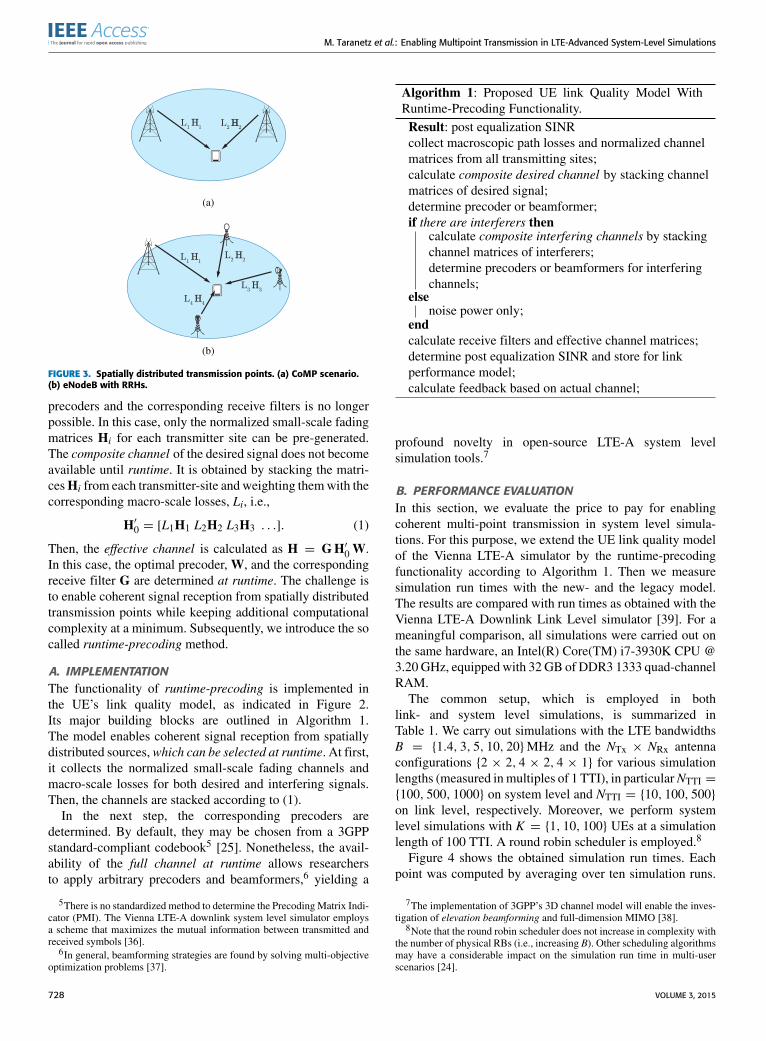
If the desired signal is received from multiple eNodeBs(e.g., in certain Coordinated Multipoint (CoMP) schemes, asindicated in Figure 3a) or from a single eNodeB with geo-graphically separated antennas (e.g., in Distributed AntennaSystem (DAS)- andRemote RadioHead (RRH) deployments,as shown in Figure 3b), a-priori computation of the optimal
4All entries of Hi have unit mean power in ensemble average.
VOLUME 3, 2015 727
M. Taranetz et al.: Enabling Multipoint Transmission in LTE-Advanced System-Level Simulations
FIGURE 3. Spatially distributed transmission points. (a) CoMP scenario.(b) eNodeB with RRHs.
precoders and the corresponding receive filters is no longerpossible. In this case, only the normalized small-scale fadingmatrices Hi for each transmitter site can be pre-generated.The composite channel of the desired signal does not becomeavailable until runtime. It is obtained by stacking the matri-cesHi from each transmitter-site and weighting themwith thecorresponding macro-scale losses, Li, i.e.,
H′0 = [L1H1 L2H2 L3H3 . . .]. (1)
Then, the effective channel is calculated as H = GH′0W.In this case, the optimal precoder, W, and the correspondingreceive filter G are determined at runtime. The challenge isto enable coherent signal reception from spatially distributedtransmission points while keeping additional computationalcomplexity at a minimum. Subsequently, we introduce the socalled runtime-precoding method.
A. IMPLEMENTATIONThe functionality of runtime-precoding is implemented inthe UE’s link quality model, as indicated in Figure 2.Its major building blocks are outlined in Algorithm 1.The model enables coherent signal reception from spatiallydistributed sources,which can be selected at runtime. At first,it collects the normalized small-scale fading channels andmacro-scale losses for both desired and interfering signals.Then, the channels are stacked according to (1).
In the next step, the corresponding precoders aredetermined. By default, they may be chosen from a 3GPPstandard-compliant codebook5 [25]. Nonetheless, the avail-ability of the full channel at runtime allows researchersto apply arbitrary precoders and beamformers,6 yielding a
5There is no standardized method to determine the PrecodingMatrix Indi-cator (PMI). The Vienna LTE-A downlink system level simulator employsa scheme that maximizes the mutual information between transmitted andreceived symbols [36].
6In general, beamforming strategies are found by solving multi-objectiveoptimization problems [37].
Algorithm 1: Proposed UE link Quality Model WithRuntime-Precoding Functionality.Result: post equalization SINRcollect macroscopic path losses and normalized channelmatrices from all transmitting sites;calculate composite desired channel by stacking channelmatrices of desired signal;determine precoder or beamformer;if there are interferers then
calculate composite interfering channels by stackingchannel matrices of interferers;determine precoders or beamformers for interferingchannels;
elsenoise power only;
endcalculate receive filters and effective channel matrices;determine post equalization SINR and store for linkperformance model;calculate feedback based on actual channel;
profound novelty in open-source LTE-A system levelsimulation tools.7
B. PERFORMANCE EVALUATIONIn this section, we evaluate the price to pay for enablingcoherent multi-point transmission in system level simula-tions. For this purpose, we extend the UE link quality modelof the Vienna LTE-A simulator by the runtime-precodingfunctionality according to Algorithm 1. Then we measuresimulation run times with the new- and the legacy model.The results are compared with run times as obtained with theVienna LTE-A Downlink Link Level simulator [39]. For ameaningful comparison, all simulations were carried out onthe same hardware, an Intel(R) Core(TM) i7-3930K CPU @3.20 GHz, equipped with 32 GB of DDR3 1333 quad-channelRAM.
The common setup, which is employed in bothlink- and system level simulations, is summarized inTable 1. We carry out simulations with the LTE bandwidthsB = {1.4, 3, 5, 10, 20}MHz and the NTx × NRx antennaconfigurations {2 × 2, 4 × 2, 4 × 1} for various simulationlengths (measured inmultiples of 1 TTI), in particularNTTI =
{100, 500, 1000} on system level and NTTI = {10, 100, 500}on link level, respectively. Moreover, we perform systemlevel simulations with K = {1, 10, 100} UEs at a simulationlength of 100 TTI. A round robin scheduler is employed.8
Figure 4 shows the obtained simulation run times. Eachpoint was computed by averaging over ten simulation runs.
7The implementation of 3GPP’s 3D channel model will enable the inves-tigation of elevation beamforming and full-dimension MIMO [38].
8Note that the round robin scheduler does not increase in complexity withthe number of physical RBs (i.e., increasing B). Other scheduling algorithmsmay have a considerable impact on the simulation run time in multi-userscenarios [24].
728 VOLUME 3, 2015
M. Taranetz et al.: Enabling Multipoint Transmission in LTE-Advanced System-Level Simulations
TABLE 1. Simulation parameters as employed for the simulation run timeevaluation.
It is observed that on system level the results scaleapproximately linearly with the simulation length NTTI, thebandwidth B and the number of UEs K. Compared to this,the link level results exhibit a slightly non-linear scalingwith B (note that on link level, only a single link is evaluated,i.e., K = 1). Both link- and system level run times show anon-linear dependence on the number of transmit- and receiveantennas, NTx and NRx, respectively. From these observa-tions, we can derive the following generic run time estimator(for a better understanding of the scaling with NTx and NRx,additional simulations with the MIMO configurations{2× 1, 4× 1} were carried out):
T[s](NTTI,B,NTx,NRx,K )
= (c0 + NTTI · K · B[MHz] · (c1 NTx + c2 NRx + c3 NTxNRx)
+. . .+NTTI · K·B2[MHz] · (c4 NTx+c5 NRx+ c6 NTxNRx))
× . . .× 1 s, (2)
where B[MHz] = B/106 Hz. Next, we compute the coef-ficients c0, . . . , c6 by linear least squares. The results aresummarized in Table 2. Compared to the legacy link qualitymodel, simulations with the new model require 1.25× longerfor initialization (represented by the coefficient c0), whichis still 52.5× faster than link level simulations. It slightlydecreases the scaling with B[MHz] · NRx (referring to c2)by 1.4× while increasing c3 (according to the scaling withB[MHz] · NTx · NRx) by 2.7×. The latter term is of particularrelevance for investigating massive MIMO scenarios with alarge number of transmit antennas. On link level, c2 (referringto a scaling proportional to B[MHz] · NRx) is 41.2× largerthan on system level, while c3 = 0 (corresponding to thescaling proportional to B[MHz] ·NRx ·NTx). On the other hand,the link level simulation run times scale with NTx · B2[MHz]and NRx · B2[MHz] (referring to c4 and c5), while system levelsimulations with both legacy- and new link quality model
exhibit no dependency on B2[MHz], i.e., c4 = 0, c5 = 0 andc6 = 0, respectively.9
IV. EXAMPLE APPLICATIONSThis section presents two examples for the application ofthe runtime-precoding enhanced UE link quality model. Thesimulation studies are carried out with the Vienna LTE-Asimulator and, to the best of our knowledge, are the firstof their kind with an openly-available LTE-A system levelsimulation tool.
A. HIGH-SPEED TRAIN SCENARIOSThis section investigates intra-site Joint Processing (JP) andinter-site Coordinated Scheduling (CS) [26] in the contextof train communications. The particular scenario representswireless access at high user mobility, which is becomingan increasingly important topic for commuting andtraveling [40]–[42]. High-speed train scenarios havethe specific feature of UEs moving in a deterministicmanner and imposing a short but heavy traffic demand on thecurrently traversed cell. To support such traffic distribu-tion, the application of RRHs is well suited [43], [44].We apply the runtime-precoding enabled RRH feature of theVienna LTE-A simulator to elaborate the impact of variousRRH collaboration schemes on the UE performance.We assume direct links between the RRHs and the UEs,i.e., the trains are not equipped with roof-mounted relaynodes. This is a particularly realistic scenario for smallercountries such as most European, where mobile providersand train operators refrain from collaborating across countryboarders.
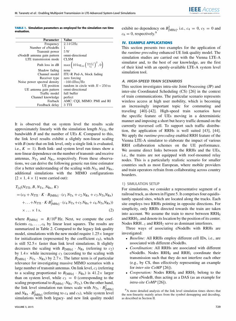
1) SIMULATION SETUPFor simulations, we consider a representative segment of arailroad track, as shown in Figure 5. It comprises four equidis-tantly spaced sites, which are located along the tracks. Eachsite employs two RRHs pointing in opposite directions. Forsimplicity, only RRHs directed towards the train are takeninto account. We assume the train to move between RRH0andRRH1, and denote its location by the position of its center.Nodes RRH−1 and RRH2 serve as dominant interferers.
Three ways of associating eNodeBs with RRHs areinvestigated:• Baseline: All RRHs employ different cell IDs, i.e., areassociated with different eNodeBs.
• Coordination: All RRHs are associated with differenteNodeBs. Nodes RRH0 and RRH1 coordinate theirtransmission such that they do not interfere each other(e.g., by CS, thus effectively representing an examplefor inter-site CoMP [26]).
• Cooperation: Nodes RRH0 and RRH1 belong to thesame eNodeB, thus acting as a DAS (as an example forintra-site CoMP [26]).
9A more detailed analysis of the link level simulation times shows thatthe non-linearity mainly arises from the symbol demapping and decoding,as described in Section II.
VOLUME 3, 2015 729

M. Taranetz et al.: Enabling Multipoint Transmission in LTE-Advanced System-Level Simulations
FIGURE 4. Simulation run times [s] for various LTE bandwidths [MHz], antenna configurations {NTX × NRX} and number of UEs. (b) system level,old model, 1 UE. (c) system level, new model, 1 UE. (d) system level, old model, 100 TTIs. (e) system level, new model, 100 TTIs. (f) link level, 1 UE.
For a fair comparison, the total transmit power per eNodeBis limited to 40W. Elaborated power allocation are omitted.In the cooperation case, serving- as well as interfering RRHstransmit with a power of 20W. The parameters for simulation
are summarized in Table 3. Transceiver impairments due tothe high speeds, such as Inter-Carrier Interference (ICI), aretaken into account by a short block fading model, which isexplained in Appendix A.
730 VOLUME 3, 2015
M. Taranetz et al.: Enabling Multipoint Transmission in LTE-Advanced System-Level Simulations
TABLE 2. Coefficients for the runtime estimator in (2) as obtained by linear least squares. Values are provided for system level simulations with thelegacy- and the new link quality model as well as for link level simulations.
FIGURE 5. Representative segment for simulation of high-speed trainscenario. RRHs are equidistantly spaced out along the tracks. The trainmoves between RRH0 and RRH1, RRH−1 and RRH2 serve as interferers.
TABLE 3. Parameters for high-speed train scenario simulations.
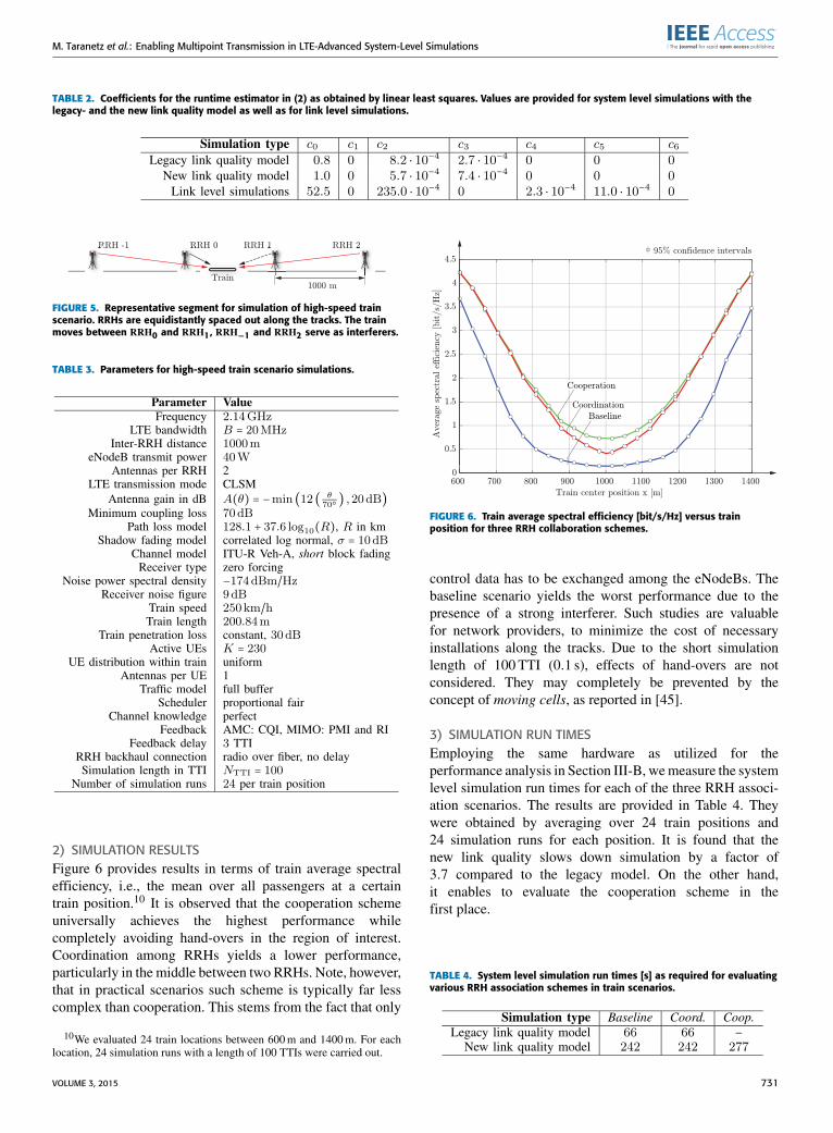
2) SIMULATION RESULTSFigure 6 provides results in terms of train average spectralefficiency, i.e., the mean over all passengers at a certaintrain position.10 It is observed that the cooperation schemeuniversally achieves the highest performance whilecompletely avoiding hand-overs in the region of interest.Coordination among RRHs yields a lower performance,particularly in the middle between two RRHs. Note, however,that in practical scenarios such scheme is typically far lesscomplex than cooperation. This stems from the fact that only
10We evaluated 24 train locations between 600m and 1400m. For eachlocation, 24 simulation runs with a length of 100 TTIs were carried out.
FIGURE 6. Train average spectral efficiency [bit/s/Hz] versus trainposition for three RRH collaboration schemes.
control data has to be exchanged among the eNodeBs. Thebaseline scenario yields the worst performance due to thepresence of a strong interferer. Such studies are valuablefor network providers, to minimize the cost of necessaryinstallations along the tracks. Due to the short simulationlength of 100 TTI (0.1 s), effects of hand-overs are notconsidered. They may completely be prevented by theconcept of moving cells, as reported in [45].
3) SIMULATION RUN TIMESEmploying the same hardware as utilized for theperformance analysis in Section III-B, wemeasure the systemlevel simulation run times for each of the three RRH associ-ation scenarios. The results are provided in Table 4. Theywere obtained by averaging over 24 train positions and24 simulation runs for each position. It is found that thenew link quality slows down simulation by a factor of3.7 compared to the legacy model. On the other hand,it enables to evaluate the cooperation scheme in thefirst place.
TABLE 4. System level simulation run times [s] as required for evaluatingvarious RRH association schemes in train scenarios.
VOLUME 3, 2015 731

M. Taranetz et al.: Enabling Multipoint Transmission in LTE-Advanced System-Level Simulations
TABLE 5. Simulation parameters for MBSFN scenario.
FIGURE 7. Example scenario for comparison of MBSFN simulations onlink level and system level.
B. MULTIMEDIA BROADCAST SINGLEFREQUENCY NETWORKSEmploying cellular networks to broadcast information toa multitude of UEs in parallel, enabling services suchas mobile radio and TV, is a desire that persists alreadysince the introduction of Multimedia Broadcast MulticastServices (MBMS) with Release 6 of UMTS (March 2005).In LTE, the concept has been extended to enhancedMBMS (eMBMS), including Multimedia Broadcast SingleFrequency Networks (MBSFNs) as a main feature. By group-ing several eNodeBs to broadcast the same informationover potentially large geographic areas, MBSFNs allowto form so-called multicast/broadcast areas, as indicatedin Figure 7. Within such area, interference between eNodeBsis not only avoided, but even exploited as useful signal.The resulting peak data rates and network capacities enablehigh-quality video broadcasting and low latency transmis-sions [2]. Currently, interest in enhanced MBMS (eMBMS)and MBSFNs is increasing within the 3GPP, as they allow toefficiently spread information that has a high user demand,e.g., at large events (venue casting) or during peak hours, aswell as to simultaneously update a vast amount of devices,which is expected to become a common use case with theadvent of the Internet of Things [46]. Moreover, they enable
public safety services, road safety applications, as well astasks of fleet control with LTE-A.1) IMPLEMENTATIONThe support of MBSFN in the Vienna LTE-A simulatorrequired some significant modifications of the program code.Signals that previously counted as interference, now haveto be considered as useful signals in the SINR calculation.However, it is not expedient to simply add up the receivedpowers from all the eNodeBs within the MBSFN area,since these base stations broadcast the same informationsynchronously. Thus, instead of adding signal powers, it isnecessary to add the channel matrices Hi of all eNodeBsi ∈ A within the MBSFN area A, i.e., HMBSFN =
∑i∈AHi.
This became feasible with the proposed runtime-precodingconcept as outlined in Section III. In an additional step, theMBSFN base stations are filtered out from the interferingeNodeBs and the corresponding effective MBSFN channelmatrices for multicast UEs are determined.
The support of MBSFN further requires a new element inthe networking hierarchy, termed MBSFN area coordinator.It determines the resource allocation for all eNodeBs withinthe corresponding MBSFN area during subframes that areutilized for multicast transmission. UEs within the MBSFNarea can subscribe to multicast groups in order to receivecertain multicast messages. The task of the MBSFN areacoordinator is to decide on the schedule of these multicastgroups within the MBSFN subframes. This group scheduleis then forwarded to the corresponding MBSFN eNodeBs,which signal the information to the multicast UEs. As anexample, a round robin multicast group scheduler has beenimplemented in the Vienna LTE-A simulator.
To enable LTE-A standard-compliant MBMS/MBSFNsimulations, a few further restrictions have to be considered inthe simulator. Multicast transmissions within MBSFN areasalways apply the extended cyclic-prefix of LTE-A, in orderto avoid inter-symbol interference due to the increaseddelay spread of the effective MBSFN channel. Furthermore,reference-symbols are more densely placed in MBSFN sub-frames, to compensate for the larger frequency selectivityof the effective channel due to the increased delay spread.Basically, on system level, both of these changes cause adifference in the number of available resource elements com-pared to unicast transmission and are taken into account whencalculating the throughput.
2) COMPARISON OF MBSFN SIMULATIONSON LINK LEVEL AND SYSTEM LEVELFor validation of the system level MBSFN implementa-tion, we cross-compare with results from link level simula-tions. A simple example scenario as illustrated in Figure 7,is employed. A larger network cannot be simulated onlink level due to computational complexity issues. In thisscenario, we consider a single MBSFN area consisting oftwoMBSFN eNodeBs and serving a total number of six UEs.An additional unicast base station serves three UEs and actsas out-of-area interferer. The direct link between a UE and
732 VOLUME 3, 2015

M. Taranetz et al.: Enabling Multipoint Transmission in LTE-Advanced System-Level Simulations
FIGURE 8. Throughput [Mbit/s] as achieved by multicast and unicast UEs. Results are obtained from link- and system level simulations with95 % confidence intervals. (a) Signal to interference ratio 10 dB. (b) Signal to interference ratio 20 dB.
its associated eNodeB has an average gain of 0 dB, whereasthe link to other UEs experiences an average gain of X dB,with X ∈ {−10,−20}.We employ a fixed transmission rateof approximately 1.2 bit per channel use (corresponding toChannel Quality Indicator (CQI) 6), to avoid the impact oftransmission rate adaptation in the results.
The results of the link level simulation (red solid) and thesystem level simulation (blue dashed) are shown in Figure 8.At high interference power, i.e., X = −10 dB, we observethat there is a marginal mismatch between link and systemlevel results, as the system level simulator slightly overesti-mates the performance. This is caused by the fact that, onsystem level, interference is considered Gaussian distributed,which is an over-simplification since the interference signalsare taken from a finite symbol alphabet (4-QAM). However,when simulating larger networks, as is commonly the case onsystem level, the law of large numbers validates the applica-tion of this Gaussian approximation. Despite the small size ofthe scenario, cross-comparing the simulation times of system-and link level exhibit a speed-up of about 3.5×.
V. CONCLUSION AND FUTURE WORKThis work presented the concept of runtime-precoding thatenables the simulation of coherent signal transmission fromspatially separated transmission points on system level. Ourapproach only alters the link quality model while preservingthe complexity gains as achieved by state of the art linkabstraction models. The price to pay for enabling coher-ent multi-point transmission turned out to be an additionalupscaling of the simulation run time which is proportional tothe product of the number of transmit- and receive antennas,respectively. On the other hand, the run times showed a linear-rather than a quadratic growth with the bandwidth, the latterbeing observed in link level simulations. Two examples forthe application of runtime precoding, inter- and intra-siteCoMP in fast train scenarios and MBSFNs, were studied.
While the results for a simple MBSFN scenario were highlyconsistent with link level simulations, achieving a simulationrun time speed-up of about 3.5×, such comparison was notpossible at all for the CoMP scenarios, as the large numberof network elements restricted evaluations to system level.The runtime-precoding feature slowed down the simulationsof the coordinated-scheduling scenario by 3.7×. On the other,it enabled the investigation of the joint transmission schemein the first place. Thus, enhancing the link quality model byruntime-precoding provides a convenient tool for simulat-ing large-scale coherent multi-point transmission scenarios,where evaluation on link level is no longer feasible due tocomplexity issues. The source code, including all thepresented new features and examples, is freely available fordownload under an academic, non-commercial use license.Our future work is directed towards 3-dimensional channelmodels [30], which will enable the investigation of elevationbeamforming and full-dimensional MIMO [38].
APPENDIXMODELING HIGH USER-MOBILITY IN THE VIENNALTE-A SYSTEM LEVEL SIMULATORThe LTE-A standard is designed to support reliable com-munication with users moving at velocities as high as500 km/h [2]. At such high speeds, several transceiverimpairments such as channel estimation errors [47] andICI between Orthogonal Frequency Division Multiplexing(OFDM) subcarriers [48], become non-negligible. These andsimilar imperfectionswere, however, not considered in legacyversions of the Vienna LTE-A simulator.
A. IMPLEMENTATIONIn this section, we explain the extension of the Vienna LTE-Asimulator to account for the suboptimal transceiver operation.In a first step, we investigate the impact of ICI on theperformance of the system. Then, we show that a similar
VOLUME 3, 2015 733

M. Taranetz et al.: Enabling Multipoint Transmission in LTE-Advanced System-Level Simulations
approach can be applied to consider other imperfections aswell. The basic requirement is that the impairments can bemodeled sufficiently well as additional Gaussian noise andare treated as such by the receivers. Although such assump-tions do not hold in general, they were found to accuratelyresemble link level simulations as well as measurements forthe considered LTE-A scenarios.
The impact of ICI on the performance of OFDM systemshas been reported in several publications. In [48], a relativelysimple expression for the average ICI power as experiencedby an OFDM transmission over a fast and frequency selec-tive Rayleigh fading channel is derived. This expression isparticularly suitable for the Vienna LTE-A simulator, as itonly depends on the maximum Doppler shift of the channeland can hence be evaluated easily. However, the model is notvery precise as it employs an average over the fading channelrather than using the current realization.
In the Vienna LTE-A simulator, the ICI power can betaken into account by modifying the post-equalization SINRcalculation in the UE link quality model (conf. Algorithm 1).In particular, we consider the ICI power as additionalGaussian noise and add it on top of the already existingthermal noise. Before, however, it is necessary to account forthe macro-scale fading as well as the UE power allocationby multiplying the ICI power as obtained from [48] with thecorresponding fading parameters (pathloss, shadow fading,antenna gain) as well as the transmit power. In case that RRHsare employed, we assume the ICI power contributions fromthe antenna arrays to be statistically independent and simplyaccumulate the individual values.
B. SIMULATIONSThe performance of this simple ICI model can be inves-tigated and verified by comparing the outcome of systemlevel simulations to the results as obtained with theVienna LTE-A link level simulator [39]. The link level sim-ulator supports a fast fading channel model, in which thechannel varies in between OFDM samples (0.52µs sam-pling rate at 1.4MHz bandwidth) and causes ICI. In contrast,the system level simulator applies a block fading channelmodel, where the channel varies only from one LTE subframe(14OFDM symbols, 1ms duration) to the next. With bothsimulators, we evaluate a single-UE-single-eNodeB scenarioas specified in Table 1. Both eNodeB and UE are equippedwith one antenna and the transmission takes place with a fixedtransmission rate of approximately 5.5 bit per channel use(corresponding to CQI 15). To highlight the impact of ICI,an unrealistically high average Signal-to-Noise Ratio (SNR)of 50 dB is employed.
Throughput and BLER results are visualized in Figure 9.The curves denoted as fast fading represent the linklevel results. The straight line in Figure 9a, denoted asBF 14 OFDM symbols without ICI, has been obtainedfrom system level simulations without adding ICI noise.In this case, the performance is independent of the uservelocity. Adding ICI noise yields the curve denoted
FIGURE 9. Throughput and BLER for fast fading channels and blockfading channels with varying fading block-length: BFx corresponds toblock fading over x OFDM symbols. ICI is considered as additionalGaussian noise. (a) Throughput reduction with growing user velocity.(b) BLER degradation with growing user velocity.
as BF 14 (block fading over 14OFDM symbols), which liessignificantly above the fast fading link level result.Thus, ICI noise alone is not sufficient to realistically representthe performance of a fast fading channel.
C. SHORT BLOCK FADINGIt is necessary to consider the increased temporal diversity ofthe channel by reducing the block-length of the block fadingchannel model. The results are illustrated by the remainingcurves in Figure 9a. Figure 9b shows the correspondingBLER curves. It is observed that a fading block-length of atmost three OFDM symbols should be employed to accuratelyreproduce the link level results. The shortening of the block-length is denoted as short block fading.
Activating ICI noise and selecting a fading block-lengthof three OFDM symbols for the system level simulation,we finally compare the throughput performance in a morecomplex scenario, where the eNodeB is equipped with
734 VOLUME 3, 2015

M. Taranetz et al.: Enabling Multipoint Transmission in LTE-Advanced System-Level Simulations
FIGURE 10. Comparison of the throughput for different user velocities asobtained from link- and system level simulations, respectively.
four transmit antennas and the UE has two receive antennas.The SNR is varied from 0 to 30 dB. We evaluate the through-put reduction with increasing user velocity, assuming thattransmission rate adaptation is activated. The results of thelink level simulation (red solid) and the system level simu-lation (blue dashed) are shown in Figure 10. We observe anaccurate match between link level and system level, substan-tiating the validity of this simple ICI model. In this setup, thesystem level simulator was roughly 35× faster.Hence, the Vienna LTE-A system level simulator was
extended to enable a reduced fading block-length, facilitatinghigh-mobility simulations. This short block fading option,however, should be utilized deliberately, as it significantlyincreases the computational complexity of the simulations.
REFERENCES[1] (Jan. 2015). ITU-R Working Party 5D (WP 5D) Contributions. [Online].
Available: http://www.itu.int/md/R07-WP5D-C/en[2] E. Dahlman, S. Parkvall, and J. Skold, 4G: LTE/LTE-Advanced for Mobile
Broadband. Amsterdam, The Netherlands: Elsevier, 2011.[3] S. Ahmadi, LTE-Advanced: A Practical Systems Approach to
Understanding 3GPP LTE Releases 10 and 11 Radio Access Technologies(ITPro Collection). Amsterdam, The Netherlands: Elsevier, 2013.
[4] Y. Wang, J. Xu, and L. Jiang, ‘‘Challenges of system-level simulations andperformance evaluation for 5G wireless networks,’’ IEEE Access, vol. 2,pp. 1553–1561, 2014.
[5] M. Gerasimenko et al., ‘‘Performance comparison of system level simula-tors for 3GPP LTE uplink,’’ in Internet of Things, Smart Spaces, and NextGeneration Networking (Lecture Notes in Computer Science), vol. 7469,S. Andreev, S. Balandin, and Y. Koucheryavy, Eds. Berlin, Germany:Springer-Verlag, 2012, pp. 186–197.
[6] (Jan. 2015). Riverbed. [Online]. Available: http://www.riverbed.com/products/performance-management-control/opnet.html?redirect=opnet
[7] (Jan. 2015). OMNeT++. [Online]. Available: http://www.omnetpp.org[8] (Mar. 2015). IT++. [Online]. Available: http://itpp.sourceforge.net/4.3.1/[9] (Jan. 2015). ns-2. [Online]. Available: http://www.isi.edu/nsnam/ns
[10] (Jan. 2015). ns-3. [Online]. Available: http://www.nsnam.org/[11] (Jan. 2015). GNS3. [Online]. Available: http://www.gns3.com/[12] S. Max, D. Bültmann, R. Jennen, and M. Schinnenburg, ‘‘Evaluation
of IMT-advanced scenarios using the open wireless network simulator,’’in Proc. Int. ICST Conf. Simulation Tools Techn., Torremolinos, Spain,Mar. 2010, p. 26.
[13] (Jan. 2015). Hurricane II WAN Emulation and Network Simula-tion. [Online]. Available: http://packetstorm.com/packetstorm-products/hurricane-ii-software
[14] (Jan. 2015). Nomor System Level Simulation. [Online]. Available: http://www.nomor.de/home/solutions-and-products/system-level-simulation
[15] D. Martín-Sacristán, J. F. Monserrat, V. Osa, and J. Cabrejas,‘‘LTE-advanced system level simulation platform for IMT-advancedevaluation,’’ Waves, 2011.
[16] Y. Li, F. Yu, S.-L. Zheng, and C.-L. Yang, ‘‘LTE system level simula-tion with MATLAB,’’ in Proc. Int. Conf. Internet Technol. Appl. (iTAP),Aug. 2011, pp. 1–4.
[17] G. Piro, L. A. Grieco, G. Boggia, F. Capozzi, and P. Camarda, ‘‘SimulatingLTE cellular systems: An open-source framework,’’ IEEE Trans. Veh.Technol., vol. 60, no. 2, pp. 498–513, Feb. 2011.
[18] (Feb. 2015). The Vienna LTE Simulators. [Online]. Available:http://www.nt.tuwien.ac.at/ltesimulator
[19] Mathworks. (Jul. 2014). MATLAB Documentation. [Online]. Available:http://www.mathworks.com/help/matlab/index.html
[20] K. Abdallah, I. Cerutti, and P. Castoldi, ‘‘Energy-efficient coordinatedsleep of LTE cells,’’ in Proc. IEEE Int. Conf. Commun. (ICC), Ottawa,ON, Canada, Jun. 2012, pp. 5238–5242.
[21] M. Carvalho and P. Vieira, ‘‘An enhanced handover oscillation controlalgorithm in LTE self-optimizing networks,’’ in Proc. IEEE Int. Symp.Wireless Pers. Multimedia Commun. (WPMC), Brest, France, Oct. 2011,pp. 1–5.
[22] M. M. Selim, M. El-Khamy, and M. El-Sharkawy, ‘‘Enhanced frequencyreuse schemes for interference management in LTE femtocell networks,’’in Proc. IEEE Int. Symp. Wireless Commun. Syst. (ISWCS), Paris, France,Aug. 2012, pp. 326–330.
[23] S. Y. Shin and D. Triwicaksono, ‘‘Radio resource control scheme formachine-to-machine communication in LTE infrastructure,’’ in Proc. Int.Conf. ICT Converg. (ICTC), Jeju Island, Korea, Oct. 2012, pp. 1–6.
[24] J. C. Ikuno, ‘‘System level modeling and optimization of the LTE down-link,’’ Ph.D. dissertation, Vienna Univ. Technol., Vienna, Austria, 2013.
[25] Evolved Universal Terrestrial Radio Access (E-UTRA); Further Advance-ments for E-UTRA Physical Layer Aspects, 3rd Generation PartnershipProject (3GPP), document Rec. TR 36.814, Mar. 2010.
[26] Coordinated Multi-Point Operation for LTE Physical Layer Aspects,3rd Generation Partnership Project (3GPP), document Rec. TR 36.819,Sep. 2013.
[27] Evolved Universal Terrestrial Radio Access (E-UTRA); Radio Fre-quency (RF) System Scenarios, 3rd Generation Partnership Project (3GPP),document Rec. TR 36.942, Oct. 2014.
[28] Guidelines for Evaluation of Radio Transmission Technologiesfor IMT-2000, ITU Radiocommunication Sector (ITU-R),document Rec. ITU-R M.1225.
[29] P. Kyösti et al., ‘‘WINNER II channel models,’’ Tech. Rep., Sep. 2007.[Online]. Available: http://www.ist-winner.org/deliverables.html
[30] Study on 3D Channel Model for LTE, 3rd Generation PartnershipProject (3GPP), document Rec. TR 36.873, Sep. 2014.
[31] R.W. Heath, Jr., M. Airy, and A. J. Paulraj, ‘‘Multiuser diversity forMIMOwireless systems with linear receivers,’’ in Proc. Conf. Rec. 35th AsilomarConf. Signals, Syst. Comput., vol. 2. Nov. 2001, pp. 1194–1199.
[32] I. Latif, F. Kaltenberger, and R. Knopp, ‘‘Link abstraction for multi-userMIMO in LTE using interference-aware receiver,’’ in Proc. IEEE WirelessCommun. Netw. Conf. (WCNC), Apr. 2012, pp. 842–846.
[33] M. Döttling et al., ‘‘Assessment of advanced beamforming and MIMOtechnologies,’’ Tech. Rep. D2.7, May 2005.
[34] S. Caban, M. Rupp, C. Mehlführer, and M.Wrulich, Evaluation of HSDPAand LTE: From Testbed Measurements to System Level Performance.New York, NY, USA: Wiley, 2011.
[35] Nortel Networks, OFDM Exponential Effective SIR Mapping Validation,EESM Simulation Results, 3rd Generation Partnership Project (3GPP),document Rec. TR R1-040089, Jan. 2004.
[36] S. Schwarz, M. Wrulich, and M. Rupp, ‘‘Mutual information based calcu-lation of the precoding matrix indicator for 3GPP UMTS/LTE,’’ in Proc.Int. ITG Workshop Smart Antennas (WSA), Bremen, Germany, Feb. 2010,pp. 52–58.
[37] E. Björnson and E. Jorswieck, ‘‘Optimal resource allocation in coordinatedmulti-cell systems,’’ Found. Trends Commun. Inf. Theory, vol. 9, nos. 2–3,pp. 113–381, 2013.
[38] Study on Elevation Beamforming/Full-Dimension (FD) MIMO for LTE,3rd Generation Partnership Project (3GPP), document Rec. TR 36.897,Dec. 2014.
[39] S. Schwarz, J. C. Ikuno, M. Simko, M. Taranetz, Q. Wang, and M. Rupp,‘‘Pushing the limits of LTE: A survey on research enhancing the standard,’’IEEE Access, vol. 1, pp. 51–62, 2013.
VOLUME 3, 2015 735
M. Taranetz et al.: Enabling Multipoint Transmission in LTE-Advanced System-Level Simulations
[40] B. Ai et al., ‘‘Challenges toward wireless communications for high-speedrailway,’’ IEEE Trans. Intell. Transp. Syst., vol. 15, no. 5, pp. 2143–2158,Oct. 2014.
[41] R. He, Z. Zhong, B. Ai, G. Wang, J. Ding, and A. F. Molisch, ‘‘Mea-surements and analysis of propagation channels in high-speed railwayviaducts,’’ IEEE Trans. Wireless Commun., vol. 12, no. 2, pp. 794–805,Feb. 2013.
[42] L. Gao, Z. Zhong, B. Ai, and L. Xiong, ‘‘Estimation of the Ricean factorin K the high speed railway scenarios,’’ in Proc. Int. ICST Conf. Commun.Netw. China, Aug. 2010, pp. 1–5.
[43] M. K. Müller, M. Taranetz, and M. Rupp. (2015). ‘‘Providing currentand future cellular services to high speed trains.’’ [Online]. Available:http://arxiv.org/abs/1505.04557
[44] M. K. Müller, M. Taranetz, and M. Rupp, ‘‘Performance of remote unitcollaboration schemes in high speed train scenarios,’’ in Proc. IEEE Veh.Technol. Conf. (VTC), Boston, MA, USA, Sep. 2015.
[45] C. D. Gavrilovich, Jr., ‘‘Broadband communication on the highways oftomorrow,’’ IEEE Commun. Mag., vol. 39, no. 4, pp. 146–154, Apr. 2001.
[46] H. Kopetz, ‘‘Internet of Things,’’ in Real-Time Systems (Real-Time Sys-tems Series). New York, NY, USA: Springer-Verlag, 2011, pp. 307–323.
[47] M. Simko, P. S. R. Diniz, Q. Wang, and M. Rupp, ‘‘Adaptive pilot-symbolpatterns for MIMO OFDM systems,’’ IEEE Trans. Wireless Commun.,vol. 12, no. 9, pp. 4705–4715, Sep. 2013.
[48] Y.-S. Choi, P. Voltz, and F. A. Cassara, ‘‘On channel estimation and detec-tion formulticarrier signals in fast and selective Rayleigh fading channels,’’IEEE Trans. Commun., vol. 49, no. 8, pp. 1375–1387, Aug. 2001.
MARTIN TARANETZ (S’07) received the B.Sc. degree in electrical engi-neering and Dipl.-Ing degree (M.Sc. equivalent) in telecommunications withhighest honors from the TUWien, Vienna, Austria, in 2008 and 2011, respec-tively. He is currently pursuing the Ph.D. degree in telecommunicationsengineering and he is employed as a University Assistant with the Instituteof Telecommunications, TU Wien. From 2014 to 2014, he was a VisitingResearcher with the Wireless Networking and Communications Group, TheUniversity of Texas at Austin. His research interests lie in the fields of wire-less communications and signal processing. In his Ph.D. thesis, he focuseson system level modeling and evaluation of heterogeneous cellular networks.He is a Reviewer for IEEE TRANSACTIONS ON WIRELESS COMMUNICATIONS andthe IEEE TRANSACTIONS ON SIGNAL PROCESSING.
THOMAS BLAZEK received the B.Sc. degree in electrical engineeringfrom the TU Wien, Vienna, Austria, in 2013. He is currently pursuingthe M.Sc. degree in telecommunications engineering. He is employed as aProject Assistant at the Institute of Telecommunications, TUWien, focusingon vehicular connectivity. His current research topics include modeling andanalysis of vehicular channels.
THOMAS KROPFREITER received the B.Sc. degree in electrical engineer-ing and the Dipl.-Ing degree (M.Sc. equivalent) in telecommunication engi-neering from the TU Wien, Vienna, Austria, in 2012 and 2014, respectively.His Diploma thesis dealt with a quantization of soft information in distributedhypothesis testing scenarios. From 2013 to 2015, he was a member of theMobile Communications Group, TU Wien, where he worked on the topicof beamforming in multicell scenarios. Since 2015, he has been employedas a Project Assistant at TU Wien, where he is currently pursuing thePh.D. degree. His current research interests are random finite sets in the fieldof target tracking and self localization.
MARTIN KLAUS MÜLLER (S’13) received the B.Eng. degree inelectrical and telecommunication engineering from the DHBW Ravensburg,Friedrichshafen, in cooperation with Rohde and Schwarz, in 2009, and theDipl.-Ing degree (M.Sc. equivalent) in telecommunications from the TUWien, Vienna, Austria, in 2013. His Diploma thesis focused on feedbackbased LTE-A measurements. He is currently pursuing the Ph.D. degree intelecommunications engineering and he is employed as a Project Assistantwith the Institute of Telecommunications, TU Wien. His current researchinterests include mobile cellular access in train- and highway scenaros andwireless communication in indoor-scenarios.
STEFAN SCHWARZ (S’10–M’14) received the B.Sc. degree in electricalengineering and the Dipl.-Ing. degree (M.Sc. equivalent) in telecommunica-tions engineering with highest distinctions in 2007 and 2009, respectively,both at the TUWien, and the Dr.techn. degree (Ph.D. equivalent) in telecom-munications engineering with highest distinctions at the TU Wien, in 2013.In 2010, he received the honorary price of the Austrian Minister of Scienceand Research, for excellent graduates of scientific and artistic universities,and in 2014, he received the INiTS Award in the category Informationand Communication Technologies for his dissertation on Limited FeedbackTransceiver Design for Downlink MIMO OFDM Cellular Networks. Since2008, he has been a Project Assistant with the Mobile CommunicationsGroup, Institute of Telecommunications, TUWien. His research interests arelocated in the broad fields of wireless communications and signal processing.In his dissertation, he focused on limited feedback single- and multiuserMIMO-OFDM communication systems, and multi-user scheduling algo-rithms. He actively serves as a Reviewer of the IEEE TRANSACTIONS
ON COMMUNICATIONS, SIGNAL PROCESSING, WIRELESS COMMUNICATIONS AND
VEHICULAR TECHNOLOGY, EURASIP Journal on Signal Processing, and Jour-nal on Wireless Communications and Networking.
MARKUS RUPP received the Dipl.-Ing. degree at the University ofSaarbrücken, Germany, in 1988, and the Dr.-Ing. degree from the Tech-nische Universität Darmstadt, Germany, in 1993, where he worked withEberhardt Hänsler on designing new algorithms for acoustical and electricalecho compensation. From 1993 to 1995, he had a post-doctoral positionwith the University of Santa Barbara, California, with S. Mitra, where heworked with A. H. Sayed on a robustness description of adaptive filters withimpact on neural networks and active noise control. From 1995 to 2001, hewas a member of Technical Staff with the Wireless Technology ResearchDepartment, Bell-Labs, Crawford Hill, NJ, where he worked on varioustopics related to adaptive equalization and rapid implementation for IS-136,802.11, and UMTS. Since 2001, he has been a Full Professor of DigitalSignal Processing in Mobile Communications at the TU Wien, where heserved as the Dean from 2005 to 2007. He was an Associate Editor of theIEEE TRANSACTIONS ON SIGNAL PROCESSING from 2002 to 2005, where he iscurrently an Associate Editor of JASP EURASIP Journal of Advances inSignal Processing, and JES EURASIP Journal on Embedded Systems. He hasbeen elected as aAdComMember of EURASIP since 2004 and serving as thePresident of EURASIP from 2009 to 2010. He has authored or co-authoredover 500 scientific papers, including 15 patents on adaptive filtering, andwireless communications.
736 VOLUME 3, 2015