russell, ontario · russell, ontario k4r 1e5 september 12, 2014 project: 13-538 attention: mr. ray...
TRANSCRIPT

Houle Chevrier Engineering Ltd.
180 Wescar Lane
Ottawa, Ontario
K0A 1L0
tel: 613.836.1422
fax: 613.836.9731
www.hceng.ca
geotechnical • environmental • hydrogeology • materials testing & inspection
Melanie Construction 900 Route 500 Russell, Ontario K4R 1E5
September 12, 2014 Project: 13-538
Attention: Mr. Ray Patenaude
Re: Preliminary Stability Assessment Honey Property Subdivision Church Street Russell, Ontario
General
The purpose of this preliminary stability assessment is to establish the ‘Erosion Hazard Limit’ for
the portion of the subdivision which will abut the Castor River (refer to Key Plan, Figure 1). This
limit constitutes a safe setback for any proposed development along the slope with respect to
slope stability. The Erosion Hazard Limit was determined based on the Natural Hazard Policies
set forth in Section 3.1 of the Provincial Policy Statements of the Planning Act of Ontario.
Current regulations restrict development within the Erosion Hazard Limit.
The slope stability analyses were carried out at Sections ‘A-A’ to ‘G-G’, inclusive, using SLIDE,
a state of the art, two dimensional limit equilibrium slope stability program. Sections ‘A-A’ to
‘D-D’ are located within the eastern portion of the site. Sections ‘E-E’ to ‘G-G’ are located within
the western portion of the site.
Sections ‘A-A’ to ‘D-D’ were surveyed and provided to us by Annis, O’Sullivan, Vollebekk Ltd.
(Ontario Land Surveyors) (refer to Site Plan, Figure 2). The slope profile along Sections ‘E-E’ to
‘G-G’ was inferred from available topographic data.
A site visit was carried out by Houle Chevrier Engineering Ltd. on August 12, 2014. At the time
of our site reconnaissance, no signs of deep seated instability, surficial tension cracks or other
obvious indications of slope movement were observed at the subject site. Minor erosion was
noted along the toe of the slope at the Castor River. The results of the slope stability analyses
are provided in Appendix A.
Report to: Melanie Construction Project: 13-538 (September 12, 2014)
2
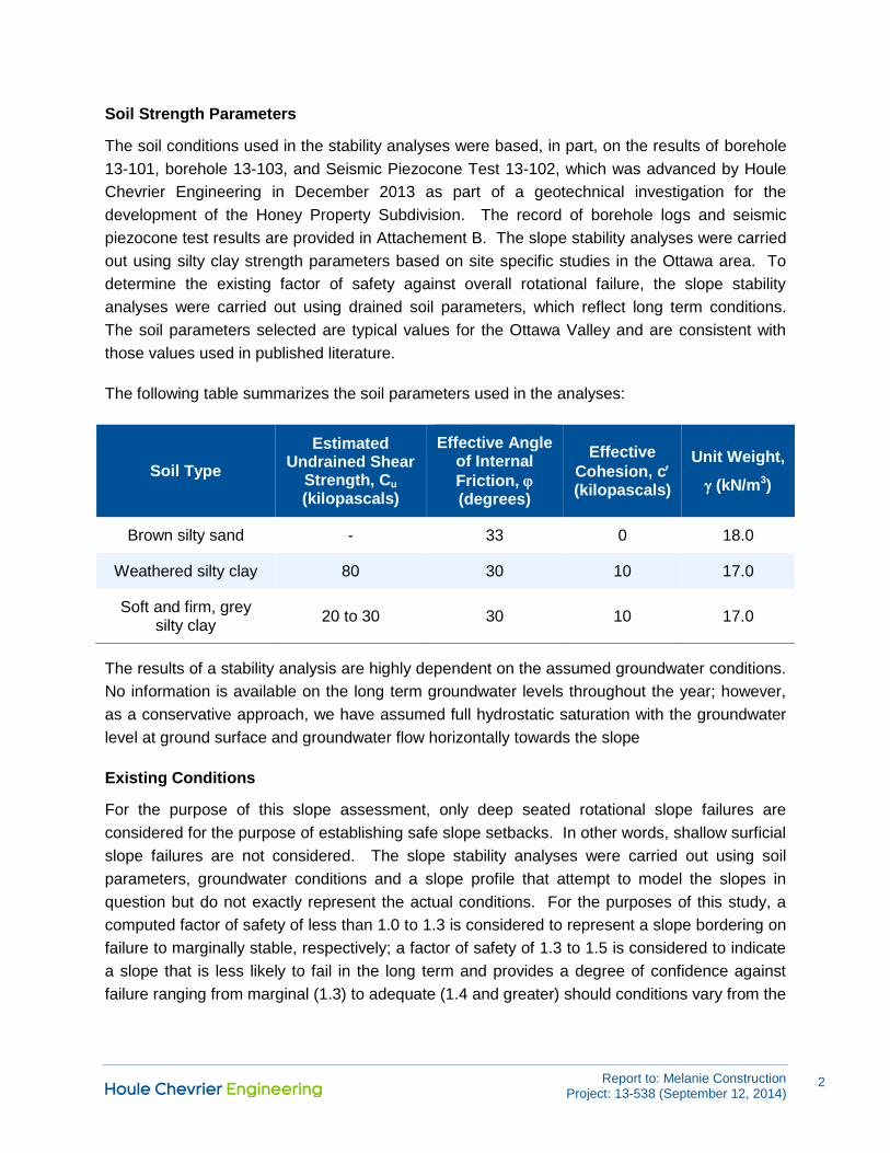
Soil Strength Parameters
The soil conditions used in the stability analyses were based, in part, on the results of borehole
13-101, borehole 13-103, and Seismic Piezocone Test 13-102, which was advanced by Houle
Chevrier Engineering in December 2013 as part of a geotechnical investigation for the
development of the Honey Property Subdivision. The record of borehole logs and seismic
piezocone test results are provided in Attachement B. The slope stability analyses were carried
out using silty clay strength parameters based on site specific studies in the Ottawa area. To
determine the existing factor of safety against overall rotational failure, the slope stability
analyses were carried out using drained soil parameters, which reflect long term conditions.
The soil parameters selected are typical values for the Ottawa Valley and are consistent with
those values used in published literature.
The following table summarizes the soil parameters used in the analyses:
Soil Type
Estimated Undrained Shear
Strength, Cu (kilopascals)
Effective Angle of Internal
Friction, (degrees)
Effective
Cohesion, c (kilopascals)
Unit Weight,
(kN/m3)
Brown silty sand - 33 0 18.0
Weathered silty clay 80 30 10 17.0
Soft and firm, grey silty clay
20 to 30 30 10 17.0
The results of a stability analysis are highly dependent on the assumed groundwater conditions.
No information is available on the long term groundwater levels throughout the year; however,
as a conservative approach, we have assumed full hydrostatic saturation with the groundwater
level at ground surface and groundwater flow horizontally towards the slope
Existing Conditions
For the purpose of this slope assessment, only deep seated rotational slope failures are
considered for the purpose of establishing safe slope setbacks. In other words, shallow surficial
slope failures are not considered. The slope stability analyses were carried out using soil
parameters, groundwater conditions and a slope profile that attempt to model the slopes in
question but do not exactly represent the actual conditions. For the purposes of this study, a
computed factor of safety of less than 1.0 to 1.3 is considered to represent a slope bordering on
failure to marginally stable, respectively; a factor of safety of 1.3 to 1.5 is considered to indicate
a slope that is less likely to fail in the long term and provides a degree of confidence against
failure ranging from marginal (1.3) to adequate (1.4 and greater) should conditions vary from the

Report to: Melanie Construction Project: 13-538 (September 12, 2014)
3
assumed conditions. A factor of safety of 1.5, or greater, is considered to indicate adequate
long term stability.
Based on the site reconnaissance, the slopes along the Castor River were divided into two
areas; Area 1 and Area 2. Area 1 is located within the eastern portion of the subject site and
includes Sections ‘A-A’ to ‘D-D’. Area 2 is located within the western portion of the subject site
and includes Section ‘E-E’ to ‘G-G’. In general, the slopes within Area 1 (i.e., the eastern
portion of the site) are steeper than the slopes within Area 2 (i.e., the western portion of the
site). For the purposes of this assessment, the erosion hazard limit (setback) within Area 1 is
based on the results of the slope stability analyses carried out for Section ‘C-C’ (the most critical
location within Area 1 based on slope geometry). The erosion hazard limit within Area 2 is
based on the results of the slope stability analyses carried out for Section ‘G-G’ (the most critical
location within Area 2 based on slope geometry).
The slope stability analysis indicates that the existing slope at Section ‘C-C’ (i.e., Area 1), in its
current configuration but in a fully saturated condition, has a factor of safety against overall
rotational failure of 1.2 for static loading conditions, which is considered marginally stable (refer
to Figure A1 in Attachment A).
At Section ‘G-G’ (i.e., Area 2), the slope stability analysis indicates that the existing slope, in its
current configuration but in a fully saturated condition, has a factor of safety against overall
rotational failure of 1.9 for static loading conditions, which is considered stable under “worst
case” conditions (refer to Figure B1 in Attachment B).
Setback Requirements
Area 1
For unstable slopes, the distance from the unstable slope to the safe setback line is called
‘Erosion Hazard Limit’. In accordance with the Ministry of Natural Resources (MNR) Technical
Guide “Understanding Natural Hazards” dated 2001, the Erosion Hazard Limit consists of three
components: (1) Stable Slope Allowance, (2) Toe Erosion Allowance, and (3) Erosion Access
Allowance.
At Section ‘C-C’, the slope stability analysis indicates the existing slope, in its current
configuration in a drained condition is considered marginally stable (refer to Figure A1 in
Attachment A). Using the same analysis results, a setback from the crest of the slope which
would provide a factor of safety of 1.5 was calculated to be about 7.8 metres.
Therefore, for this preliminary analysis, a minimum setback of 7.8 metres measured
perpendicular from the crest of the slope along the Castor River is required.
The watercourse is located at the toe of the slope at this site. In accordance with the MNR
documents, we have included a Toe Erosion Allowance of 8 metres to allow for continual

Report to: Melanie Construction Project: 13-538 (September 12, 2014)
4
erosion at the toe of the slope. The Toe Erosion Allowance is applied at the crest of the slope
(refer to Figure A1 in Attachment A).
The MNR procedures also include the application of a 6 metre wide Erosion Access Allowance
beyond the Toe Erosion Allowance to allow for access by equipment to repair a possible failed
slope. For the purposes of this preliminary assessment, we have included a 6 metre wide
Erosion Access Allowance (refer to Figure A1 in Attachment A). Consideration could be given
to constructing a pedestrian/bicycle path within the 6 metre zone defined by the Erosion Access
Allowance, provided that heavy and emergency vehicle access is not hindered.
Therefore, the Erosion Hazard Limit for the slopes within Area 1 is located about 21.8 metres
from the crest of the existing slopes (refer to Figure 2). We recommend that the top of slope be
staked by Houle Chevrier Engineering Ltd. and tied-in by a land surveyor so that the Erosion
Hazard Limit can be accurately shown on a plan.
Area 2
At Section ‘G-G’, the slope stability analysis indicates that the existing slope, in its current
configurations, has a factor of safety against failure of greater than 1.5 (refer to Figures B1 in
Attachment B). Therefore, the Stable Slope Allowance described in the MNR procedures is not
required.
As previously indicated, the Castor River is located at the toe of the slopes at this site. In
accordance with the MNR documents, we have included a Toe Erosion Allowance of 8 metres
to allow for continual erosion at the toe of the slope. The Toe Erosion Allowance is applied at
the crest of the slope (refer to Figure B1 in Attachment B).
The MNR procedures also include the application of a 6 metre wide Erosion Access Allowance
beyond the Toe Erosion Allowance to allow for access by equipment to repair a possible failed
slope. For the purposes of this preliminary assessment, we have included a 6 metre wide
Erosion Access Allowance (refer to Figure B1 in Attachment B).
Therefore, the Erosion Hazard Limit for the slopes within Area 2 is located about 14.0 metres
from the crest of the existing slopes (refer to Figure 2). We recommend that the top of slope be
staked by Houle Chevrier Engineering Ltd. and tied-in by a land surveyor so that the Erosion
Hazard Limit can be accurately shown on a plan.
Seismic Slope Stability
Sections ‘C-C’ and ‘G-G’ were also analysed for pseudo-static (seismic) conditions. A seismic
coefficient of 0.2 was used in the pseudo-static analysis (i.e., half of the Peak Ground
Acceleration for the Ottawa area, based on Seismic Site Class E and the OBC 2012).

Report to: Melanie Construction Project: 13-538 (September 12, 2014)
5
For seismic loading conditions, the Erosion Hazard Limit could consist of only the Stable Slope
Allowance (i.e., the Toe Erosion Allowance and Erosion Access Allowance are not considered).
During a seismic event, the Stable Slope Allowance is the area between the crest of the slope
and location where a factor of safety of greater than 1.1 against overall rotational failure is
calculated. A Toe Erosion Allowance is not considered since erosion is not the trigger of
seismic slope instability. Furthermore, an Erosion Access Allowance is also not considered
given that, in general, the philosophy for seismic design corresponds to post-disaster conditions
(i.e.,to avoid immediate collapse and loss of life).
At Section ‘C-C’, the slope stability analysis indicates that the existing slope, in its current
configuration but fully saturated, has a factor of safety against failure of greater than 1.1 for
pseudo-static (seismic) conditions at a distance of about 15.0 metres from the crest of the slope
(refer to Figure A2 in Attachment A). At Section ‘G-G’, the slope stability analysis indicates that
the existing slope has a factor of safety against failure of greater than 1.1 for pseudo-static
(seismic) conditions. Therefore, the Erosion Hazard Limit determined for static loading
conditions governs for this site.
ADDITIONAL CONSIDERATIONS
The existing vegetation and trees along the slope should be maintained, to ensure the stability
of the slope is not affected. As part of the overall site grading for any future development, no
additional surface water should be directed towards the slope unless adequate erosion control
measures are incorporated. This could cause erosion of the slope and could also negatively
affect the stability of the slope. Final plans and finished grades for any proposed development
adjacent to the slope should be reviewed by a geotechnical engineer to ensure that the
guidelines provided on this report have been interpreted as intended.

Report to: Melanie Construction Project: 13-538 (September 12, 2014)
6
We trust that this letter is sufficient for your purposes. If you have any questions concerning this
information or if we can be of further assistance to you on this project, please call.
Luc Bouchard, P.Eng.
Craig Houle, M.Eng., P.Eng. Principal
12 Sep 2014

FIGURE 1 KEY PLAN
Date: September 2014
Project: 13-538
N.T.S
SITE

70.52
BH13-105
70.96
BH13-106
70.52
13-102
SCPTu
68.37
BH13-103
D
'
D
B'
B
A'
A
C'
C
68.43
BH13-101
BH13-104
F
G
E'F'
G'
APPROXIMATE BOREHOLE LOCATION IN PLAN, CURRENT
INVESTIGATION BY HOULE CHEVRIER ENGINEERING LTD.
LEGEND
BH13-103
68.43
BOREHOLE ELEVATION IN METRES (GEODETIC DATUM)
Figure Project No.
Scale
Drawing
Project
Drawn By
Date
Checked By
13-538
D.J.R.
September 2014
L.B.
2 0
Revision No.
100500
1:2500
150m
A'
A
CROSS SECTION LOCATION IN PLAN
SCPTu
13-102
SEISMIC PIEZOCONE TEST
EROSION HAZARD LIMIT (APPROXIMATE)
AREA 1
AREA 2

Report to: Melanie Construction Project: 13-538 (September 12, 2014)
ATTACHMENT A
Slope Stability Analyses
Area 1 - Section ‘C-C’
Figures A1 and A2

R.R. 2 180 Wescar Lane Carp, Ontario
K0A 1L0 [email protected]
(613) 836-1422 Fax: 836 9731
FIGURE A1
PROJECT: 13-538
DATE: August 2014
SLOPE STABILITY ANALYSIS HONEY PROPERTY SUBDIVISION
SECTION C-C
Loading Conditions: Static
Groundwater Conditions: Full Hydrostatic Saturation
Soil Properties: Drained

R.R. 2 180 Wescar Lane Carp, Ontario
K0A 1L0 [email protected]
(613) 836-1422 Fax: 836 9731
FIGURE A2
PROJECT: 13-538
DATE: August 2014
SLOPE STABILITY ANALYSIS HONEY PROPERTY SUBDIVISION
SECTION C-C
Loading Conditions: Pseudo-Static (0.20)
Groundwater Conditions: Full Hydrostatic Saturation
Soil Properties: Drained

Report to: Melanie Construction Project: 13-538 (September 12, 2014)
ATTACHMENT B
Slope Stability Analyses
Area 2 - Section ‘G-G’
Figures B1 and B2

R.R. 2 180 Wescar Lane Carp, Ontario
K0A 1L0 [email protected]
(613) 836-1422 Fax: 836 9731
FIGURE B1
PROJECT: 13-538
DATE: September 2014
SLOPE STABILITY ANALYSIS HONEY PROPERTY SUBDIVISION
SECTION G-G
Loading Conditions: Static
Groundwater Conditions: Full Hydrostatic Saturation
Soil Properties: Drained

R.R. 2 180 Wescar Lane Carp, Ontario
K0A 1L0 [email protected]
(613) 836-1422 Fax: 836 9731
FIGURE B2
PROJECT: 13-538
DATE: September 2014
SLOPE STABILITY ANALYSIS HONEY PROPERTY SUBDIVISION
SECTION G-G
Loading Conditions: Pseudo-Static (0.20)
Soil Properties: Undrained

Report to: Melanie Construction Project: 13-538 (September 12, 2014)
ATTACHMENT C
Record of Borehole Logs
Seismic Piezocone Test Results

1
2
3
4
5
6
50D.O.
50D.O.
50D.O.
50D.O.
50D.O.
50D.O.
3
5
4
1
W.H.
P.M.
Pow
er A
uger
0.20
2.49
7.01
Bentonite
Filter Sand
51mmdiameter,3.05m longslotted PVCpipe
Groundwaterlevel at 0.85metresbelowgroundsurface(elevation67.58metresgeodeticdatum) onJanuary 10,2014.
68.23
65.94
61.42
200m
m D
iam
eter
Hol
low
Ste
m A
uger
Dark brown silty sand some organicmaterial (TOPSOIL)
Very stiff, reddish grey brown SILTYCLAY (WEATHERED CRUST)
Soft to firm, grey SILTY CLAY
End of Borehole
LOGGED: A.N.
CHECKED:
SOIL PROFILE
Ground Surface
DEPTH(m)
20 40
DEPTH SCALE
1 to 50
HYDRAULIC CONDUCTIVITY,k, cm/s
80
SHEET 1 OF 1
DATUM: Geodetic
SPT HAMMER: 63.5 kg; drop 0.76 m
68.43
DYNAMIC PENETRATIONRESISTANCE, BLOWS/0.3m
SHEAR STRENGTHCu, kPa
-7 -6 -5 -4
NU
MB
ER
TY
PE
PIEZOMETEROR
STANDPIPEINSTALLATION
AD
DIT
ION
AL
LAB
. TE
ST
ING
RECORD OF BOREHOLE 13-101
SAMPLES
WATER CONTENT, PERCENT
20
Q -U -
60 80
W
ELEV.
DE
PT
H S
CA
LEM
ET
RE
S
BO
RIN
G M
ET
HO
D
10 10 10 10
nat. V -rem. V -
40 60
DESCRIPTION
BLO
WS
/0.3
m
20
60
40
0
1
2
3
4
5
6
7
8
9
10
Wp Wl80
PROJECT: 13-538
LOCATION: See Borehole Location Plan, Figure 2
BORING DATE: December 10, 2013
ST
RA
TA
PLO
T
BO
RE
HO
LE R
EC
OR
D 2
012
WIT
H L
AB
WC
BO
RE
HO
LE L
OG
S D
EC
EM
BE
R 1
3 20
13.G
PJ
7/
4/1
4

1
2
3
4
5
6
50D.O.
50D.O.
50D.O.
50D.O.
50D.O.
50D.O.
1
9
1
P.M.
P.M.
1
Pow
er A
uger
0.36
1.52
6.71
7.62
NativeBackfill
Bentonite
NativeBackfill
Bentonite
70.16
69.00
63.81
62.90
200m
m D
iam
eter
Hol
low
Ste
m A
uger
Dark brown silty sand some organicmaterial (TOPSOIL)
Loose, brown SILTY SAND, trace clay
Wet/saturated
Soft, grey SILTY CLAY
Firm, grey SILTY CLAY
End of Borehole
LOGGED: A.N.
CHECKED:
SOIL PROFILE
Ground Surface
DEPTH(m)
20 40
DEPTH SCALE
1 to 50
HYDRAULIC CONDUCTIVITY,k, cm/s
80
SHEET 1 OF 1
DATUM: Geodetic
SPT HAMMER: 63.5 kg; drop 0.76 m
70.52
DYNAMIC PENETRATIONRESISTANCE, BLOWS/0.3m
SHEAR STRENGTHCu, kPa
-7 -6 -5 -4
NU
MB
ER
TY
PE
PIEZOMETEROR
STANDPIPEINSTALLATION
AD
DIT
ION
AL
LAB
. TE
ST
ING
RECORD OF BOREHOLE 13-103
SAMPLES
WATER CONTENT, PERCENT
20
Q -U -
60 80
W
ELEV.
DE
PT
H S
CA
LEM
ET
RE
S
BO
RIN
G M
ET
HO
D
10 10 10 10
nat. V -rem. V -
40 60
DESCRIPTION
BLO
WS
/0.3
m
20
60
40
0
1
2
3
4
5
6
7
8
9
10
Wp Wl80
PROJECT: 13-538
LOCATION: See Borehole Location Plan, Figure 2
BORING DATE: December 10, 2013
ST
RA
TA
PLO
T
BO
RE
HO
LE R
EC
OR
D 2
012
WIT
H L
AB
WC
BO
RE
HO
LE L
OG
S D
EC
EM
BE
R 1
3 20
13.G
PJ
7/
4/1
4

Houle Chevrier Engineering Ltd.Operator ALN Cone Number DPG1148 Location Russell
Job No. 13-538 Date and Time 12/12/2013 11:19:49 AM CPT No. CPT-13-102
Groundwater Depth 1.52 m Ground Elev. 68.37
0
1
2
3
4
5
6
7
0 4000 Tip Resistance
Qt KPA 0 140 Local Friction
Fs KPA -100 700 Pore Pressure
Pw KPA 0 14 Friction Ratio
Fs/Qt (%) 0 12
1 - sensitive fine grained
2 - organic material
3 - clay
4 - silty clay to clay
5 - clayey silt to silty clay
6 - sandy silt to clayey silt
7 - silty sand to sandy silt
8 - sand to silty sand
9 - sand
10 - gravelly sand to sand
11 - very stiff fine grained (*)
12 - sand to clayey sand (*)
CPT DATA REMARKS
DE
PTH
(m)
SO
ILB
EH
AV
IOR
TYP
E
Groundwater assumed 1.5-2m
Qc = 16,000 Kpa at 6.80-m