rv3, rv5, rv8 and rv12 rotary vane vacuum pumps · the edwards rv rotary vane pump is shown in...
TRANSCRIPT
Instruction Manual
To Our Websiteidealvac.com
RV3, RV5, RV8 and RV12Rotary Vane Vacuum Pumps
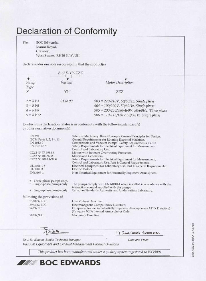

Declaration of Incorporation
* When installed according to this instruction manual.This product has been manufactured under a quality system registered to ISO9001
Date and Place
We, BOC Edwards,Manor Royal,Crawley,West Sussex, RH10 2LW, UK
declare under our sole responsibility that the machine(s)
A 65X-YY-ZZZ
Pump Variant Motor DescriptionTypeX YY ZZZ
2 = RV3 01 to 99 965 = NEMA Bareshaft3 = RV5 970 = ISO Bareshaft4 = RV85 = RV12
to which this declaration relates is intended to be incorporated into other equipment and not to function independently. The machine(s) is in conformity with the following standard(s) or other normative document(s)
EN 292 * Safety of Machinery: Basic Concepts, General Principles for Design.EN1012-2 * Compressors and Vacuum Pumps - Safety Requirements Part 2.
The machine(s) must not be put into service until the equipment into which it is incorporated has been brought into conformity with the provisions of the Machinery Directive, 98/37/EC.
P900
-76-
000
Is
sue
F
2B01
-010
23.4.99 Shoneham

dcs/
0169
/050
3
CONTENTS
Section Title Page
1 INTRODUCTION 11.1 Scope and definitions 11.2 ATEX directive implications 21.3 Description 41.4 Performance modes and controls 41.4.1 Mode selector 51.4.2 Gas-ballast control 51.5 Construction 5
2 TECHNICAL DATA 62.1 Operating and storage conditions 62.2 Performance 62.2.1 General 62.2.2 Performance characteristics 102.3 Mechanical data 112.3.1 General 112.3.2 Noise and vibration data 112.4 Electrical data: single-phase pumps 112.5 Electrical data: three-phase pumps 142.6 Lubrication data 14
3 INSTALLATION 153.1 Safety 153.2 System design considerations 153.3 Unpack and inspect 163.4 Locate the pump 163.5 Fill the pump with oil 183.6 Electrical installation: single-phase pumps 183.6.1 Check and configure the motor 183.6.2 Connect the pump to your electrical supply 193.6.3 Check the direction of rotation 213.7 Electrical installation: three-phase pumps 213.7.1 Check and configure the motor 213.7.2 Connect the pump to your electrical supply 223.7.3 Check the direction of rotation 223.8 Inlet and outlet connections 233.9 Leak-test the system 243.10 Electrical installation 243.10.1 Check and configure the motor 243.10.2 Connect the motor to the electrical supply 243.11 Check the direction of rotation 25
RV3, RV5, RV8 and RV12 Rotary Vane Pumps i
Section Title Page
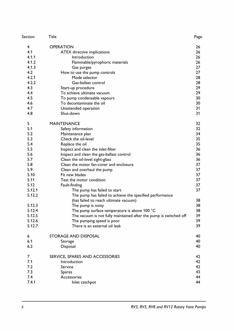
4 OPERATION 264.1 ATEX directive implications 264.1.1 Introduction 264.1.2 Flammable/pyrophoric materials 264.1.3 Gas purges 274.2 How to use the pump controls 274.2.1 Mode selector 284.2.2 Gas-ballast control 284.3 Start-up procedure 294.4 To achieve ultimate vacuum 294.5 To pump condensable vapours 304.6 To decontaminate the oil 304.7 Unattended operation 314.8 Shut-down 31
5 MAINTENANCE 325.1 Safety information 325.2 Maintenance plan 345.3 Check the oil-level 355.4 Replace the oil 355.5 Inspect and clean the inlet-filter 365.6 Inspect and clean the gas-ballast control 365.7 Clean the oil-level sight-glass 365.8 Clean the motor fan-cover and enclosure 375.9 Clean and overhaul the pump 375.10 Fit new blades 375.11 Test the motor condition 375.12 Fault-finding 375.12.1 The pump has failed to start 375.12.2 The pump has failed to achieve the specified performance
(has failed to reach ultimate vacuum) 385.12.3 The pump is noisy 385.12.4 The pump surface temperature is above 100 °C 385.12.5 The vacuum is not fully maintained after the pump is switched off 395.12.6 The pumping speed is poor 395.12.7 There is an external oil leak 39
6 STORAGE AND DISPOSAL 406.1 Storage 406.2 Disposal 40
7 SERVICE, SPARES AND ACCESSORIES 427.1 Introduction 427.2 Service 427.3 Spares 437.4 Accessories 447.4.1 Inlet catchpot 44
ii RV3, RV5, RV8 and RV12 Rotary Vane Pumps
Section Title Page
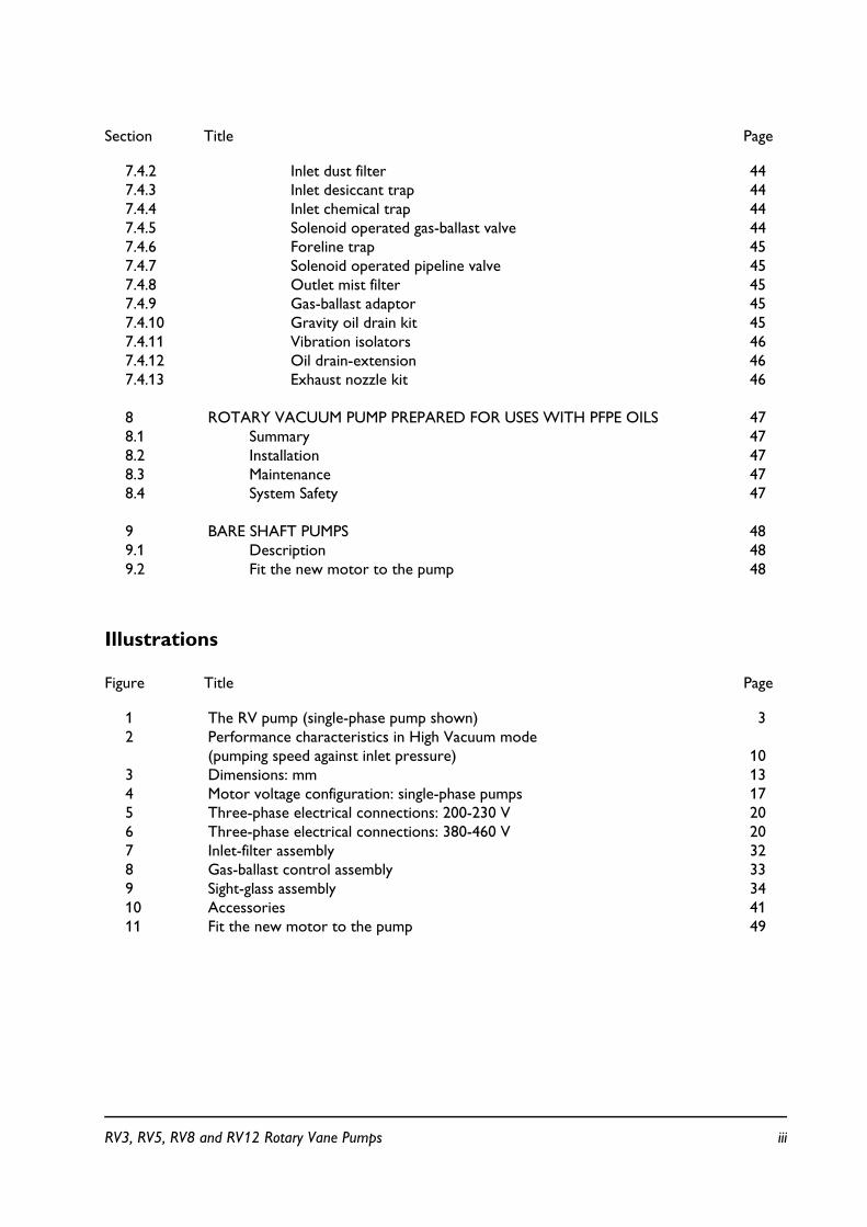
7.4.2 Inlet dust filter 447.4.3 Inlet desiccant trap 447.4.4 Inlet chemical trap 447.4.5 Solenoid operated gas-ballast valve 447.4.6 Foreline trap 457.4.7 Solenoid operated pipeline valve 457.4.8 Outlet mist filter 457.4.9 Gas-ballast adaptor 457.4.10 Gravity oil drain kit 457.4.11 Vibration isolators 467.4.12 Oil drain-extension 467.4.13 Exhaust nozzle kit 46
8 ROTARY VACUUM PUMP PREPARED FOR USES WITH PFPE OILS 478.1 Summary 478.2 Installation 478.3 Maintenance 478.4 System Safety 47
9 BARE SHAFT PUMPS 489.1 Description 489.2 Fit the new motor to the pump 48
Illustrations
Figure Title Page
1 The RV pump (single-phase pump shown) 32 Performance characteristics in High Vacuum mode
(pumping speed against inlet pressure) 103 Dimensions: mm 134 Motor voltage configuration: single-phase pumps 175 Three-phase electrical connections: 200-230 V 206 Three-phase electrical connections: 380-460 V 207 Inlet-filter assembly 328 Gas-ballast control assembly 339 Sight-glass assembly 3410 Accessories 4111 Fit the new motor to the pump 49
RV3, RV5, RV8 and RV12 Rotary Vane Pumps iii

Tables
Table Title Page
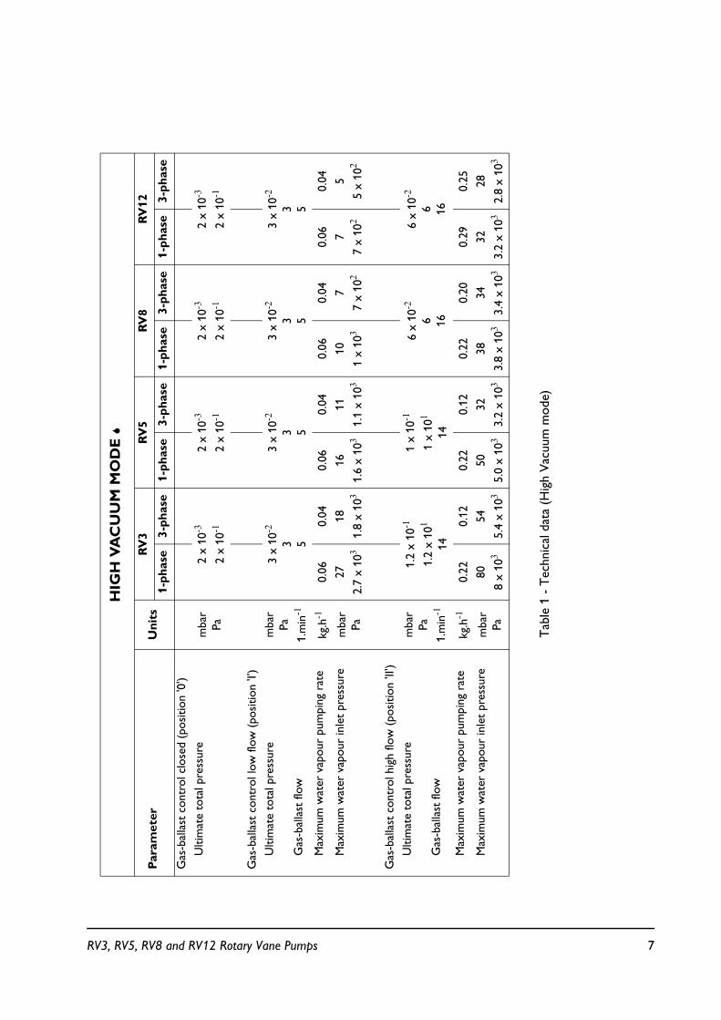
1 Technical data (High Vacuum mode) 72 Technical data (High Throughput mode) 83 Performance characteristics 94 Electrical data (single-phase pumps with Item Numbers -903 or -906) 125 Electrical data (single-phase pumps with Item Numbers -904) 126 Electrical data (three-phase pumps with Item Numbers -905) 147 Maintenance plan 348 Spares and Accessories 43
Associated publications
Publication title Publication Number
Vacuum pump and vacuum system safety P300-20-000
iv RV3, RV5, RV8 and RV12 Rotary Vane Pumps

1 INTRODUCTION
1.1 Scope and definitions
This manual provides installation, operation and maintenance instructions for the EdwardsRV3, RV5, RV8 and RV12 Rotary Vane Pumps. You must use your pump as specified in thismanual. Read this manual before you install and operate your pump.
Important safety information is highlighted as WARNING and CAUTION instructions; youmust obey these instructions. The use of WARNINGS and CAUTIONS is defined below.
The units used throughout this manual conform to the SI international system of units ofmeasurement.
In accordance with the recommendations of IEC1010, the following warning symbols are onthe pump:
Warning - refer to accompanying documents.
Warning - risk of electric shock.
Warning - hot surface.
Warning - risk of catastrophic failure.
WARNING
Warnings are given where failure to observe the instruction could result in injury or death to people.
CAUTION
Cautions are given where failure to observe the instruction could result in damage to the equipment, associated equipment and process.
RV3, RV5, RV8 and RV12 Rotary Vane Pumps 1

1.2 ATEX directive implications
! This equipment is designed to meet the requirements of Group II Category 3 equipmentin accordance with Directive 94/9/EC of the European Parliament and the Council of 23rdMarch 1994 on the approximation of the laws of the Member States concerning equipmentand protective systems intended for use in potentially explosive atmospheres. (The ATEXDirective).
The ATEX Category 3 applies in respect of potential ignition sources internal to theequipment. An ATEX Category has not been assigned in respect of potential ignitionsources on the outside of the equipment as the equipment has not been designed for usewhere there is an external potentially explosive atmosphere.
There is no potential source of ignition within the pump during normal operation but theremay be potential sources of ignition under conditions of predicted and rare malfunction asdefined in the Directive. Accordingly, although the pump is designed to pump flammablematerials and mixtures, operating procedures should ensure that under all normal andreasonably predicted conditions, these materials and mixtures are not within explosivelimits. Category 3 is considered appropriate for the avoidance of ignition in the case of arare malfunction which allows flammable materials or mixtures to pass through the pumpwhile within their explosive limits.
! When flammable or pyrophoric materials are present within the equipment you must:
! Not allow air to enter the equipment.
! Ensure that the system is leak tight.
! Use an inert gas purge (for example, a nitrogen purge) to dilute any flammable gases orvapours entering the pump inlet, and/or use an inert gas purge to reduce theconcentration of flammable gases or vapours in the pump and in the exhaust pipelineto less than one quarter of the gases' published lower explosive limits (LEL).
! For further information, please contact BOC Edwards: refer to the Addresses page at theend of this manual for details of your nearest BOC Edwards company.
2 RV3, RV5, RV8 and RV12 Rotary Vane Pumps

Figure 1 - The RV pump (single-phase pump shown)
1. Electrical inlet-connector
2. Voltage indicator3. Lifting handle (lifting
bracket on RV8 and RV12 pumps and Bareshaft)
4. NW25 inlet-port5. Gas-ballast control6. Oil filler-plug7. NW25 outlet-port8. Oil-level sight-glass9. Oil drain-plug
10. Rubber feet (4 off)11. Mode selector12. On/off switch (single-
phase pumps only)13. Motor fan-cover14. Correct direction of
rotation
RV3, RV5, RV8 and RV12 Rotary Vane Pumps 3

1.3 Description
The Edwards RV rotary vane pump is shown in Figure 1. Refer to Figure 1 for item numbersin brackets in the following descriptions. The RV pumps are two-stage, oil-sealed, sliding-vanevacuum pumps. The pump has NW25 inlet (4) and outlet (7) ports, a gas-ballast control (5)and a mode selector (11). When the pump is switched off, an inlet-valve seals the inlet andprevents the suck-back of air and oil into the vacuum system.
The RV3 and RV5 pumps have a retractable lifting handle (3). The RV8 and the RV12 pumpsare fitted with a lifting bracket for use with suitable lifting equipment.
An oil-pump delivers pressurised oil to the vacuum pumping mechanism in the RV pump. Youcan inspect the level and condition of the oil in the oil-box through a sight-glass (8). Two oilfiller-plugs (6) and an oil drain-plug (9) are provided on the oil-box.
The pump mechanism is driven directly by a single-phase or three-phase electric motorthrough a flexible motor-coupling. The motor is totally enclosed and is cooled by the motorcooling-fan which directs air along the motor fins. The pumps are cooled by an additional fanattached to the motor-coupling.
Single-phase motors are fitted with an on/off switch (12) and a thermal overload device. Whenthe motor is too hot, the thermal overload device switches off the pump. The thermaloverload device has an automatic reset; when the motor cools down, the device resets and(unless you have incorporated suitable control equipment which must be manually reset: seeSection 3.6.2), the motor will restart.
The pump is mounted on a base plate on rubber feet (10). Details of suitable vibration isolatorsand other accessories are provided in Section 7.
If the pump is prepared for uses with PFPE oils, details are provided in Section 8.
1.4 Performance modes and controls
The pump has two controls : the mode selector (11) and the gas-ballast control (5). Sixpossible combinations of these controls allow for a wide choice of operating characteristics soyou can optimize the performance of the pump for a given application.
4 RV3, RV5, RV8 and RV12 Rotary Vane Pumps

1.4.1 Mode selector
The mode selector has two positions; refer to Section 4.2 to select these positions.Throughout the rest of this manual, the following convention is used:
! The High Vacuum mode is specified by the " symbol.
! The High Throughput mode is specified by the " symbol.
With the mode selector set to High Vacuum mode ", pressurised oil is fed to the low vacuumstage only. In this mode of operation, the pump provides the best possible ultimate vacuum.
With the mode selector set to High Throughput mode ", pressurised oil is fed to the highvacuum and low vacuum stages. In this mode of operation, the pump can sustain long-term highinlet pressures.
1.4.2 Gas-ballast control
To pump high vapour loads, gas-ballast is delivered into the pump to prevent condensation ofthe vapour carried by the pumped gases.
Air can be introduced to the low vacuum stage through the gas-ballast valve. Alternatively, aninert gas such as nitrogen can be supplied through a suitable external valve.
The gas-ballast control has three positions :
! Closed (position '0')
! Low flow (position 'I')
! High flow (position 'II').
1.5 Construction
The pump-shafts and rotors are made of high-grade cast-iron. The pump-body and oil-box aremade from cast-aluminium. All surfaces of the pump which are exposed to the pumped gasesare free from copper, zinc and cadmium.
Other materials of construction include fluorocarbon elastomer, nitrile, silicon, chemically-resistant polymers, nickel and stainless steel.
RV3, RV5, RV8 and RV12 Rotary Vane Pumps 5

2 TECHNICAL DATA
2.1 Operating and storage conditions
Ambient temperature range (operation) 12 to 40 °CNormal surface temperature ofthe pump-body at ultimate vacuum (operation),ambient temperature of 20 °C 50 to 70 °CMaximum humidity (operation) 90% RHAmbient temperature range (storage) -30 to 70 °C
2.2 Performance
2.2.1 General
Note: In Tables 1 and 2, total pressures have been measured by a capacitance diaphragm gauge ona vacuum chamber without a cold trap, as specified by Pneurop Standard 6602 (1979).
High Vacuum mode " performance See Table 1High Throughput mode " performance See Table 2Suckback protection 1 x 10⁻⁵ mbar.ls-1, 1 x 10⁻³ Pa.ls-1
Maximum initial pressure risewith no gas ballast flow 1 x 10⁻¹ mbar.l, 1 x 101 Pa.l
RV3 RV5 RV8 RV12Maximum displacement (m3h-1)
50 Hz electrical supply 3.7 5.8 9.7 14.260 Hz electrical supply 4.5 7.0 11.7 17.0
Maximum pumping speed (m3h-1)Pneurop 6602 (1979)
50 Hz electrical supply 3.3 5.1 8.5 12.060 Hz electrical supply 3.9 6.2 10.0 14.2
Maximum permitted inlet pressure andgas-ballast inlet pressure: bar gauge 0.5 0.5 0.5 0.5
Pa 1.5 x 10⁵ 1.5 x 10⁵ 1.5 x 10⁵ 1.5 x 10⁵
Maximum permitted outlet pressure:bar gauge 1 1 1 1
Pa 2 x 10⁵ 2 x 10⁵ 2 x 10⁵ 2 x 10⁵
6 RV3, RV5, RV8 and RV12 Rotary Vane Pumps
Tab
le 1
- T
echn
ical
dat
a (H
igh
Vac
uum
mod
e)
HIG
H V
AC
UU
M M
OD
E "
Par
amet
erU
nit
sR
V3
RV
5R
V8
RV
12
1-p
has
e3-
ph
ase
1-p
has
e3-
ph
ase
1-p
has
e3-
ph
ase
1-p
has
e3-
ph
ase
Gas
-bal
last
con
trol
clo
sed
(pos
ition
'0')
U
ltim
ate
tota
l pre
ssur
em
bar
Pa2
x 10-3
2 x
10-1
2 x
10-3
2 x
10-1
2 x
10-3
2 x
10-1
2 x
10-3
2 x
10-1
Gas
-bal
last
con
trol
low
flow
(po
sitio
n 'I'
)
U
ltim
ate
tota
l pre
ssur
e
G
as-b
alla
st fl
ow
mba
rPa
1.m
in-1
3 x
10-2
3 5
3 x
10-2
3 5
3 x
10-2
3 5
3 x
10-2
3 5
M
axim
um w
ater
vap
our
pum
ping
rat
ekg
.h-1
0.06
0.04
0.06
0.04
0.06
0.04
0.06
0.04
M
axim
um w
ater
vap
our
inle
t pr
essu
rem
bar
Pa27
2.7
x 103
18
1.8
x 103
16
1.6
x 103
11
1.1
x 103
10
1 x
103
7
7 x
102
7
7 x
102
5
5 x
102
Gas
-bal
last
con
trol
hig
h flo
w (
posi
tion
'II')
U
ltim
ate
tota
l pre
ssur
e
G
as-b
alla
st fl
ow
mba
rPa
1.m
in-1
1.2
x 10-1
1.2
x 101
14
1 x
10-1
1 x
101
14
6 x
10-2
6 16
6 x
10-2
6 16
M
axim
um w
ater
vap
our
pum
ping
rat
e
kg.h-1
0.22
0.12
0.22
0.12
0.22
0.20
0.29
0.25
M
axim
um w
ater
vap
our
inle
t pr
essu
rem
bar
Pa80
8 x
103
54
5.4
x 103
50
5.0
x 103
32
3.2
x 103
38
3.8
x 103
34
3.4
x 103
32
3.2
x 103
28
2.8
x 103
RV3, RV5, RV8 and RV12 Rotary Vane Pumps 7

Tab
le 2
- T
echn
ical
dat
a (H
igh
Thr
ough
put
mod
e)
HIG
H T
HR
OU
GH
PU
T M
OD
E "
Par
amet
erU
nit
sR
V3
RV
5R
V8
RV
12
1-p
has
e3-
ph
ase
1-p
has
e3-
ph
ase
1-p
has
e3-
ph
ase
1-p
has
e3-
ph
ase
Gas
-bal
last
con
trol
clo
sed
(pos
ition
'0')
U
ltim
ate
tota
l pre
ssur
em
bar
Pa3
x 10-2
33
x 10-2
33
x 10-2
33
x 10-2
3
Gas
-bal
last
con
trol
low
flow
(po
sitio
n 'I'
)
U
ltim
ate
tota
l pre
ssur
e
G
as-b
alla
st fl
ow
mba
rPa
1.m
in-1
6 x
10-2
6 5
6 x
10-2
6 5
4 x
10-2
4 5
4 x
10-2
4 5
M
axim
um w
ater
vap
our
pum
ping
rat
e
Max
imum
wat
er v
apou
r in
let
pres
sure
kg.h-1
mba
rPa
0.06 27
2.7
x 103
0.04 18
1.8
x 103
0.06 16
1.6
x 103
0.04 11
1.1
x 103
0.06 10
1 x
103
0.04 7
7 x
102
0.06 7
7 x
102
0.04 5
5 x
102
Gas
-bal
last
con
trol
hig
h flo
w (
posi
tion
'II')
U
ltim
ate
tota
l pre
ssur
e
G
as-b
alla
st fl
ow
mba
rPa
1.m
in-1
1.2
x 10-1
1.2
x 101
14
1 x
10-1
1 x
101
14
6 x
10-2
6 16
6 x
10-2
6 16
M
axim
um w
ater
vap
our
pum
ping
rat
e
Max
imum
wat
er v
apou
r in
let
pres
sure
kg.h-1
mba
rPa
0.22 80
8 x
103
0.12 54
5.4
x 103
0.22 50
5.0
x 103
0.12 32
3.2
x 103
0.22 38
3.8
x 103
0.20 34
3.4
x 103
0.29 32
3.2
x 103
0.25 28
2.8
x 103
8 RV3, RV5, RV8 and RV12 Rotary Vane Pumps

MO
DE
S
EL
EC
TO
R
PO
SIT
ION
GA
S-B
AL
LA
ST
CO
NT
RO
L
Clo
sed
(p
osi
tio
n '0
')L
ow f
low
(p
osi
tio
n 'I
')H
igh
flow
(p
osi
tio
n 'I
I')
Hig
h Va
cuum
m
ode
"
Ulti
mat
e to
tal p
ress
ure
Ulti
mat
e to
tal p
resu
reU
ltim
ate
tota
l pre
ssur
e
mba
rPa
mba
rPa
mba
rPa
2 x
10-3
2 x
10-1
3 x
10-2
31.
2 x
10-1
(RV
3)
1.0
x 10-1
(RV
5)
6.0
x 10-2
(RV
B/12
)
1.2
x 101
(RV
3)
1.0
x 101
(RV
5)6.
0
(RV
8/12
)
Use
for
the
best
ulti
mat
e pr
essu
re
Max
imum
wat
er v
apou
r pu
mpi
ng r
ate
Max
imum
wat
er v
apou
r pu
mpi
ng r
ate
1-ph
ase
pum
ps3-
phas
e pu
mps
1-ph
ase
pum
ps3-
phas
e pu
mps
0.06
kg.
h-1
0.04
kg.
h-1
0.22
kg.
h-1
(RV
3/5/
8)
0.29
kg.
h-1
(RV
12)
0.12
kg.
h-1
(RV
3/5)
0.20
kg.
h-1
(RV
8)
0.25
kg.
h-1
(RV
12)
Hig
h T
hrou
ghpu
tm
ode
"
Ulti
mat
e to
tal p
ress
ure
Ulti
mat
e to
tal p
resu
reU
ltim
ate
tota
l pre
ssur
e
mba
rPa
mba
rPa
mba
rPa
3 x
10-2
36
x 10-2
(RV
3/5)
4 x
10-2
(RV
8/12
)
6 (R
V3/
5)4
(RV
8/12
)
1.2
x 10-1
(RV
3)
1.0
x 10-1
(RV
5)
6.0
x 10-2
(RV
8/12
)
1.2
x 101
(RV
3)
1.0
x 101
(RV
5)6.
0
(RV
8/12
)
Use
for
cont
inuo
us in
let
pres
sure
abo
ve
50 m
bar/
5 x
103
Pa
Max
imum
wat
er v
apou
r pu
mpi
ng r
ate
Max
imum
wat
er v
apou
r pu
mpi
ng r
ate
1-ph
ase
pum
ps3-
phas
e pu
mps
1-ph
ase
pum
ps3-
phas
e pu
mps
0.06
kg.
h-1
0.04
kg.
h-1
0.22
kg.
h-1
(RV
3/5/
8)
0.29
kg.
h-1
(RV
12)
0.12
kg.
h-1
(RV
3/5)
0.20
kg.
h-1
(RV
8)
0.25
kg.
h-1
(RV
12)
Tab
le 3
- P
erfo
rman
ce c
hara
cter
istic
s
RV3, RV5, RV8 and RV12 Rotary Vane Pumps 9

Figure 2 - Performance characteristics in High Vacuum mode(pumping speed against inlet pressure)
2.2.2 Performance characteristics
Note: Typical for hydrocarbon oil
The following performance characteristics are typical for hydrocarbon oil.
The positions of the mode selector and the gas-ballast control define the performancecharacteristics of the pump. These performance characteristics are listed fully in Tables 1and 2.
Table 3 gives the ultimate vacuum and maximum water vapour inlet pressure for each of thesix possible combinations of control positions. The curves 0, I, and II in Figure 2 show therelationship between inlet pressure and pumping speed for High Vacuum mode ".
10 RV3, RV5, RV8 and RV12 Rotary Vane Pumps

2.3 Mechanical data
2.3.1 General
Overall dimensions See Figure 3Degree of protection (IEC 34-5: 1981) IP44 (single-phase pumps)
IP54 (three-phase pumps)Maximum tilt angle 10 °Motor rotational speed (50 Hz supply) 1470 r.min-1
Motor rotational speed (60 Hz supply) 1760 r.min-1
RV3 RV5 RV8 RV12Maximum mass, without oil (kg) 21.6 21.5 26.0 26.3Maximum mass, Bareshaft pump (kg) 14.0 14.0 16.5 17.5
2.3.2 Noise and vibration data
Sound pressure, measured at ultimate vacuum 1 metre from 1-phase 3-phasethe end of the pump to ISO 11201, High Vacuum mode ",50 Hz operation 48 dB (A) 50 dB(A)Vibration severity: measured at the inlet port to ISO 2372 (1974) Class 1C Class 1C
2.4 Electrical data: single-phase pumps
Note: We recommend that you use fuses of the maximum ratings specified in Tables 4 and 5. Youmust not use fuses of a higher rating.
The dual-voltage, dual-frequency motor is designed for a single-phase electrical supply and issuitable for 50 Hz or 60 Hz operation. The motor can be manually switched between nominalsupply voltages of 110-120 V and 220-240 V (refer to Section 3.6.1).
When you start a cold pump, the motor will draw the start-up current shown in Tables 4 and5 for up to several seconds, so you must use a slow-blow fuse to prevent unnecessary fusefailure during pump start-up. Within five minutes, as the oil in the pump warms up, the currentdrawn will slowly reduce to the full load current specified in Tables 4 and 5.
RV3, RV5, RV8 and RV12 Rotary Vane Pumps 11

Table 4 - Electrical data (single-phase pumps with Item Numbers -903 or -906)
Table 5 - Electrical data (single-phase pumps with Item Numbers -904)
Note: The fuse type chosen should be either, time delay type CC or a type M, or in the UK they shouldbe to BS 88.
PumpNominal
supply (V)Frequency
(Hz)Power (W)
Full load current (A)
Start-up current
Maximum fuse rating
(A)
RV3 and RV5
220-240230-240
110115-120
50605060
250300250300
2.42.24.64.4
15.615.229.431.5
551010
RV8 and RV12
220-240230-240
110115-120
50605060
450550450550
4.03.67.87.2
18.018.034.034.0
551313
PumpNominal
supply (V)Frequency
(Hz)Power (W)
Full load current (A)
Start-up current
Maximum fuse rating
(A)
RV3 and RV5
200200-210
100100-105
50605060
250300250300
2.82.45.44.6
19.419.537.039.0
551010
RV8 and RV12
200200-210
100100-105
50605060
450550450550
3.93.87.67.6
21.020.640.041.5
551313
12 RV3, RV5, RV8 and RV12 Rotary Vane Pumps

* Single-phase pumps † Three-phase pumps
Figure 3 - Dimensions: mm
Pump A B C D E F G H I J K
RV3RV5RV8RV12
430*430*470*490*
429†429†469†489†
158158158158
225225225225
127127161181
29293535
78787878
230230230230
120120120120
37373737
32323232
--
261261
1. On/off switch (single-phase pumps only)2. Lifting bracket (RV8 and RV12 pumps only)
and all Bareshaft pumps
A Top view of single-phase pumpB Side view of single-phase pumpC Side view of three-phase pumpD Front view of single-phase pumpE Bare shaft pump
RV3, RV5, RV8 and RV12 Rotary Vane Pumps 13

2.5 Electrical data: three-phase pumps
The dual-voltage, dual-frequency motor is designed for a three-phase electrical supply and issuitable for 50Hz or 60Hz operation. The motor can be manually switched between nominalsupply voltages of 220-240v and 380-460v (refer to section 3.7.1). Pumps are supplied pre-setfor nominal 380-460v electrical supplies.
When you start a cold pump, the motor will draw the start-up current shown in Table 6 forup to 0.5 seconds. The current will then reduce quickly as the motor reaches rated rotationalspeed. Within 5 minutes, as the oil and pump warms up, the current drawn will slowly reduceto a maximum of the full load current specified in Table 6.
When you start a warm pump, the motor will draw the start-up current shown in Table 6 forup to 0.5 seconds. The current drawn will then immediately fall to a maximum of the full loadcurrent.
Electrical short-circuit and ground-fault protection of the pump will be provided by fitting ClassCC fuses of the values shown in Table 6 at the point of connection to the supply. If these arenot available in your country of use, Type aM European fuses of the same rating can also beused.
Table 6 - Electrical data (three-phase pumps with Item Numbers -905)
2.6 Lubrication data
Note: Edwards Health and Safety Data sheets for rotary pump oils are available on request.
Recommended oil* Edwards Ultragrade 19 in hydrocarbonprepared pumps.Krtox 1506 or Fomblin 06/6 in PFPE prepared pumps.
Oil capacity (litres) RV3 RV5 RV8 RV12Maximum 0.70 0.70 0.75 1.00Minimum 0.42 0.42 0.45 0.65
* To operate the pump when the ambient temperature is outside the limits specified in Section 2.1, orto optimise the pump performance when you pump condensible vapours, you may need to use adifferent oil.
PumpNominal
supply (V)Frequency
(Hz)Power (W)
Full load current (A)
Start-up current (A)
Recommended fuse rating (A)
RV3 and RV5
200-220200-230380-415
460
50605060
250300250300
1.71.71.01.0
10.210.25.77.0
2.52.52.52.5
RV8 and RV12
200-220200-230380-415
460
50605060
450550450550
2.52.91.51.5
14.012.09.08.7
44
2.52.5
14 RV3, RV5, RV8 and RV12 Rotary Vane Pumps
3 INSTALLATION
3.1 Safety
You must ensure that the RV pump is suitable for your application. If you have any doubt asto the suitability of the RV pump for your application, refer to the Edwards guidelines onvacuum pump and vacuum system safety (see the Associated publications at the end of theContents list at the front of this manual).
The installation of your RV pump must be performed by a suitably trained and supervisedtechnician. Obey the safety instructions listed below when you install the pump, especiallywhen you connect the pump into an existing system. Details of specific safety precautions aregiven at the appropriate point in the instructions.
! Wear the appropriate safety-clothing when you come into contact with contaminatedcomponents.
! Vent and purge your vacuum system before you start installation work.
! Ensure that the installation technician is familiar with the safety procedures which relate tothe pump-oil and the products handled by the pumping system. Take suitable precautionsto avoid the inhalation of oil mist and excessive skin contact with pump-oil, as prolongedexposure can be harmful.
! Disconnect the other components in the pumping system from the electrical supply so thatthey cannot be operated accidentally.
3.2 System design considerations
Consider the following points when you design your pumping system:
! Use a suitable valve to isolate the pump from your vacuum system if you need to allow thepump to warm up before you pump condensable vapours, or to provide additional systemprotection when the pump is switched off.
! Avoid high levels of heat input to the pump from the process gases, otherwise the pumpmay overheat and seize, and cause the motor thermal overload device to open.
! If you use the pump in a high ambient temperature and have a high gas throughput, thetemperature of the pump-body may exceed 70 °C and you must fit suitable guards toprevent contact with hot surfaces.
! Make sure that the exhaust pipeline cannot become blocked. If you have an exhaust-isolation valve, make sure that you cannot operate the pump with the valve closed.
WARNING
The hydrocarbon prepared RV pump is not recommended for pumping hazardous substances. PFPE prepared pumps are suitable for oxygen applications. Refer to Section 8
RV3, RV5, RV8 and RV12 Rotary Vane Pumps 15

! Provide for a purge of inert gas when you shut down the pumping system, to dilutedangerous gases to safe concentrations. A suitable gas ballast adaptor for introduction ofpurge gas into the pump is available as an accessory (see Section 7.4.9).
3.3 Unpack and inspect
Remove all packing materials, remove the pump from its packing-box, remove the protectivecovers from the inlet and outlet-ports and inspect the pump. If the pump is damaged, notifyyour supplier and the carrier in writing within three days; state the Item Number of the pumptogether with your order number and your supplier's invoice number. Retain all the packingmaterials for inspection. Do not use the pump if it is damaged.
If the pump is not to be used immediately, replace the protective covers. Store the pump insuitable conditions, as described in Section 6.1.
3.4 Locate the pump
The RV3 and RV5 pumps have a lifting handle which you can use to move the pump by hand.If you wish to use mechanical lifting equipment, do not attach the equipment to the handle; forstability, use slings around the motor and the pump-body.
Do not lift the RV8 and RV12 pumps by hand; attach your mechanical lifting equipment to thelifting bracket on the pump. You do not need to use slings to move the RV8 and RV12 pumps.
Provide a firm, level platform for the pump. Locate the pump so that the oil-level sight-glass isvisible and the oil filler-plug, oil drain-plug, mode selector and gas-ballast control are accessible.
If your pump will be located inside an enclosure, make sure that there is adequate ventilationat both ends of the pump, so that the ambient temperature around the pump does not exceed40 °C. There must be a minimum space of 25 mm between the pump and the enclosure walls.
WARNING
Use suitable lifting equipment to move the RV8 or RV12 pump.The mass of the RV8 and RV12 pumps is approximately 26 kg.
16 RV3, RV5, RV8 and RV12 Rotary Vane Pumps
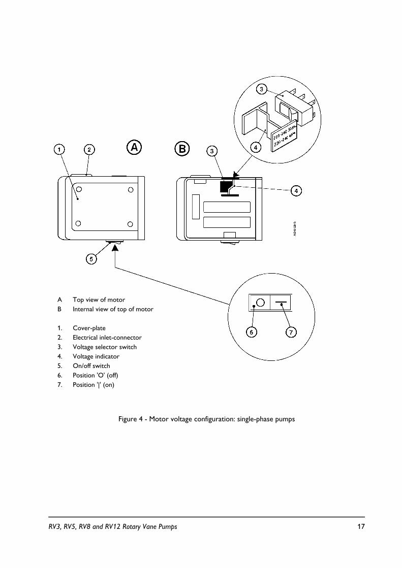
Figure 4 - Motor voltage configuration: single-phase pumps
A Top view of motorB Internal view of top of motor
1. Cover-plate2. Electrical inlet-connector3. Voltage selector switch4. Voltage indicator5. On/off switch6. Position 'O' (off)7. Position '|' (on)
RV3, RV5, RV8 and RV12 Rotary Vane Pumps 17

3.5 Fill the pump with oil
Fill the pump with oil as described below. Refer to Section 2 for the recommended oil. Referto Figure 1 for the item numbers in brackets.
1. Remove one of the oil filler-plugs (6)
2. Pour oil into the pump until the oil-level just reaches the MAX mark on the bezel at thetop of the sight-glass (8). If the oil-level goes above the MAX mark, remove the drain-plug(9) and drain the excess oil from the pump.
3. After a few minutes, recheck the oil-level. If the oil-level is now below the MAX mark, pourmore oil into the pump.
4. Refit the oil filler-plug. Tighten the plug firmly by hand. Do not overtighten.
3.6 Electrical installation: single-phase pumps
Note: If you have a bare shaft pump read section 9 before continuing. Some parts of Section 3.6will not be applicable, depending on the type of motor fitted.
3.6.1 Check and configure the motor
Refer to Figure 4 for the item numbers in brackets.
Ensure that the voltage shown on the voltage indicator (4) in the motor-cover correspondswith your electrical supply voltage. If it does not, you must change the configuration of thepump-motor to match your electrical supply voltage; use the procedure below.
1. Undo the four screws, remove the cover-plate (1) and lift out the voltage indicatormoulding (4).
2. Press the voltage selector switch (3) to select the alternative position.
3. Turn the voltage indicator moulding over so that the outer panel shows the requiredvoltage. Refit the moulding.
WARNING
If you use a hydrocarbon prepared pump, you must not use the pump to process oxygen in concentrations greater than 25 % in volume. If you do, there is a risk of fire or explosion in
the oil-box of the pump. PFPE prepared pumps are available. Refer to Section 8
CAUTION
Ensure that the motor is correctly configured for your electrical supply. If you operate the pump when the motor is not correctly configured for the electrical supply, you will damage
the motor.
18 RV3, RV5, RV8 and RV12 Rotary Vane Pumps

4. Refit the cover-plate and secure it with the four screws.
3.6.2 Connect the pump to your electrical supply
Notes: In the UK, if you use a 13 A plug, it must comply with BS1363A and be fitted with a 13 A fusewhich complies with BS1362.
To prevent automatic restart of the pump-motor if the electrical supply is restored after anelectrical supply failure, connect the pump to the electrical supply through suitable controlequipment which must be reset manually after an electrical supply failure.
Make the electrical connections to the pump-motor with an IEC 320 cable socket (coldcondition type) that satisfies your local electrical standards.
To maintain compliance with CSA standards, you must only use CSA/UL certified electricalsupply cables and connectors. Cables must be SJT rated (minimum) and must incorporate anearth conductor. The conductors in the cable must be a minimum of 18 AWG.
If your RV pump was supplied with an electrical supply cable, the cable will be fitted with amoulded IEC connector at one end. The other end of the cable may be fitted with a plugsuitable for your local electrical supply. A cable without a plug will contain wires colour codedas follows:
Green and yellow earthBlue neutralBrown live
1. Ensure that the on/off switch on the motor (Figure 4, item 5) is in the 'off' position.
2. Insert the moulded IEC connector at the end of the cable into the electrical inlet-connectoron the motor (Figure 4, item 2).
3. Connect the plug (if fitted) at the other end of the cable to your electrical supply. If a plugis not fitted, connect the wires in the cable to the correct terminals of your electricalsupply.
WARNING
Ensure that the electrical installation of the RV pump conforms with your local and national safety requirements. It must be connected to a suitably fused and protected electrical supply
and a suitable earth point.
RV3, RV5, RV8 and RV12 Rotary Vane Pumps 19
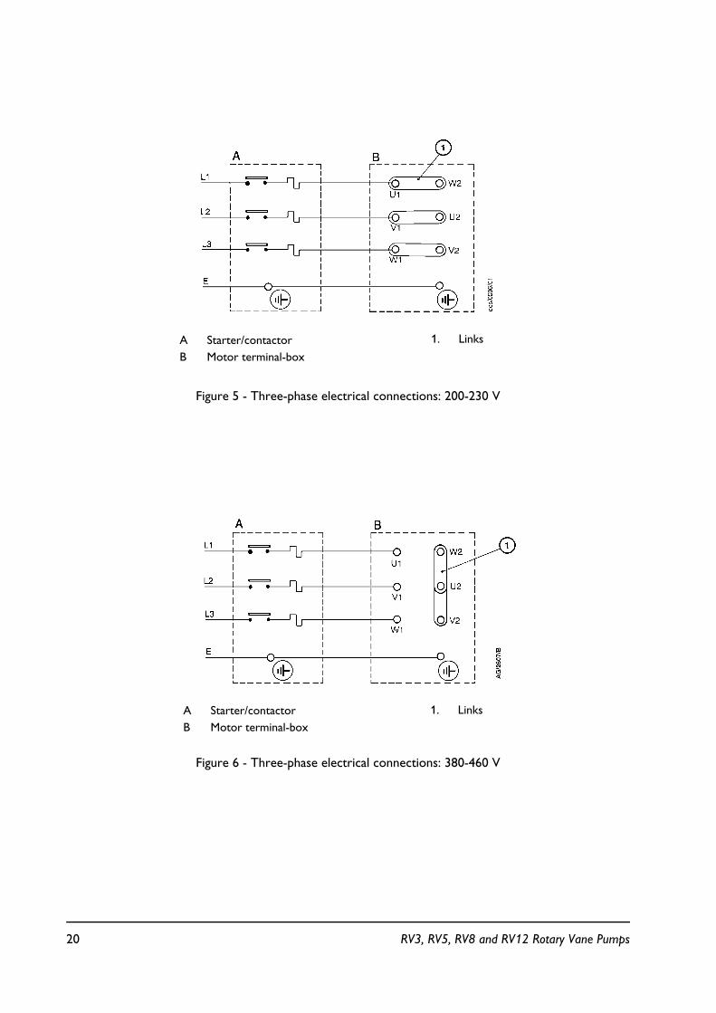
Figure 5 - Three-phase electrical connections: 200-230 V
Figure 6 - Three-phase electrical connections: 380-460 V
A Starter/contactorB Motor terminal-box
1. Links
A Starter/contactorB Motor terminal-box
1. Links
20 RV3, RV5, RV8 and RV12 Rotary Vane Pumps
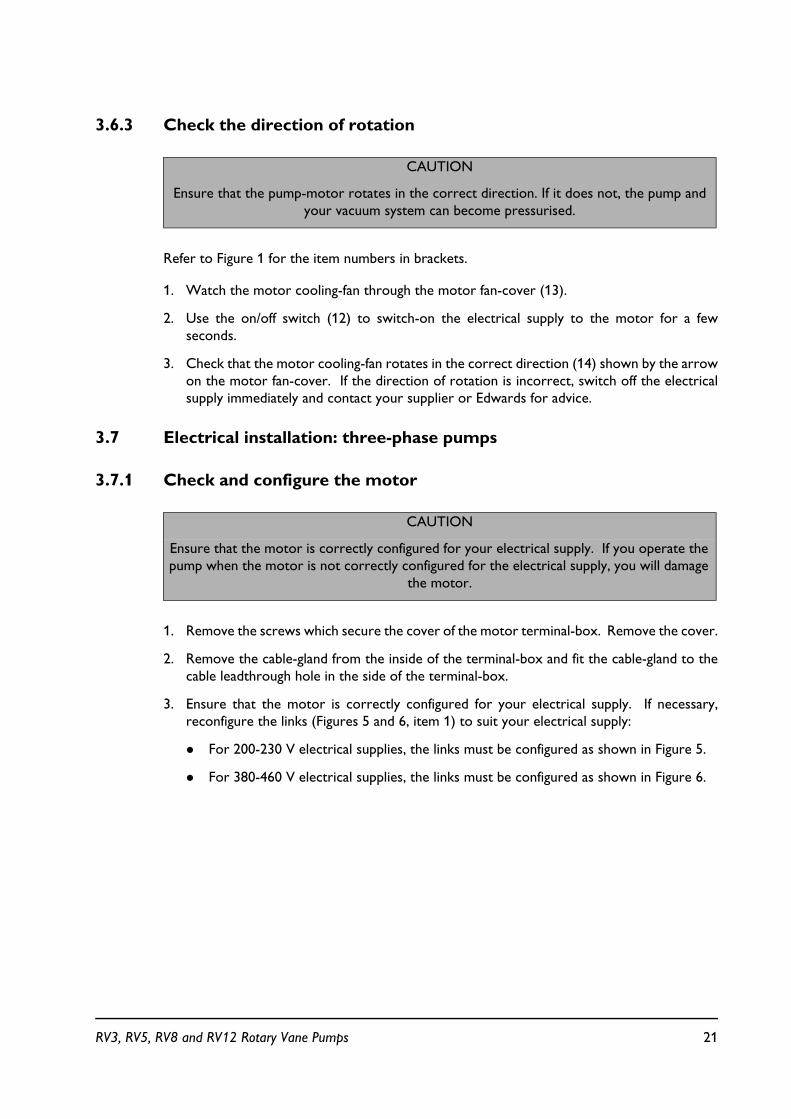
3.6.3 Check the direction of rotation
Refer to Figure 1 for the item numbers in brackets.
1. Watch the motor cooling-fan through the motor fan-cover (13).
2. Use the on/off switch (12) to switch-on the electrical supply to the motor for a fewseconds.
3. Check that the motor cooling-fan rotates in the correct direction (14) shown by the arrowon the motor fan-cover. If the direction of rotation is incorrect, switch off the electricalsupply immediately and contact your supplier or Edwards for advice.
3.7 Electrical installation: three-phase pumps
3.7.1 Check and configure the motor
1. Remove the screws which secure the cover of the motor terminal-box. Remove the cover.
2. Remove the cable-gland from the inside of the terminal-box and fit the cable-gland to thecable leadthrough hole in the side of the terminal-box.
3. Ensure that the motor is correctly configured for your electrical supply. If necessary,reconfigure the links (Figures 5 and 6, item 1) to suit your electrical supply:
! For 200-230 V electrical supplies, the links must be configured as shown in Figure 5.
! For 380-460 V electrical supplies, the links must be configured as shown in Figure 6.
CAUTION
Ensure that the pump-motor rotates in the correct direction. If it does not, the pump and your vacuum system can become pressurised.
CAUTION
Ensure that the motor is correctly configured for your electrical supply. If you operate the pump when the motor is not correctly configured for the electrical supply, you will damage
the motor.
RV3, RV5, RV8 and RV12 Rotary Vane Pumps 21

3.7.2 Connect the pump to your electrical supply
Notes: To prevent automatic restart of the pump-motor if the electrical supply is restored after anelectrical supply failure, connect the pump to the electrical supply through suitable controlequipment which must be reset manually after an electrical supply failure.
To maintain compliance with CSA (Canadian Standards Association) standards, you mustincorporate a switch or circuit breaker in the pump electrical supply. The switch or circuitbreaker must be close to the pump and easily accessible, and must be clearly marked toidentify that it is the electrical supply disconnection device for the pump.
We recommend that you connect the electrical supply to the motor through a starter orcircuit breaker which has thermal over-current protection which can be adjusted to suit thefull load current ratings shown in Table 4. The fuse ratings in Table 4 are provided for guidanceonly. The supplier of your thermal over-current protection device may specify different valuesto ensure correct operation of the fuse and the over-current protection device. Ensure thatthe fuse you use is suitable for the starting currents given in Table 4.
1. Pass the electrical supply cable through the cable-gland. The diameter of the electricalsupply cable should be in the range 7 to 11 mm.
2. Use insulated crimped connectors to connect the wires in the cable to the terminals U1,V1 and W1 in the terminal-box as shown in Figures 5 and 6.
3. Ensure that the cover gasket is correctly positioned, then refit the cover to the terminal-box and secure with the screws. Tighten the strain-relief nut on the cable-gland.
3.7.3 Check the direction of rotation
1. Refer to Figure 1. Watch the motor cooling-fan through the motor fan-cover (13).
2. Switch-on the electrical supply to the motor for a few seconds.
3. Check that the motor cooling-fan rotates in the correct direction shown by the arrow onthe motor mounting plate. If the direction of rotation is incorrect:
! Switch off the electrical supply immediately.
! Isolate the pump from the electrical supply.
WARNING
Ensure that the electrical installation of the RV pump conforms with your local and national safety requirements. It must be connected to a suitably fused and protected electrical supply
and a suitable earth point.
CAUTION
Ensure that the pump-motor rotates in the correct direction. If it does not, the pump and your vacuum system can become pressurised.
22 RV3, RV5, RV8 and RV12 Rotary Vane Pumps

! Remove the terminal-box cover and swap wires L1 and L3: see Figures 5 and 6.
! Refit the cover to the terminal-box.
3.8 Inlet and outlet connections
Before you connect the pump to your vacuum system, fit the centring-ring and inlet-filter(supplied with the pump) to the pump inlet-port (see Figure 5).
Take note of the following information when you connect the pump to your vacuum system.Refer to Section 7 for details of the accessories mentioned below. Use standard NW25 fittings(not supplied) when you connect the pump.
! For optimum pumping speeds, ensure that the pipeline connected to the pump-inlet is asshort as possible and has an internal diameter of 25 mm or larger.
! Support the vacuum pipelines to prevent loading of the coupling-joints.
! If necessary, incorporate flexible bellows in your system pipelines to reduce thetransmission of vibration and to prevent loading of coupling-joints. If you use flexiblebellows, you must ensure that you use bellows which have a maximum pressure ratingwhich is greater than the highest pressure that can be generated in your system. Werecommend that you use Edwards flexible bellows.
! Use a suitable inlet trap if you pump condensable vapours or if you use the pump for verydusty applications.
! Use a suitable valve to isolate the pump from your vacuum system if you need to pumpcondensable vapours or maintain vacuum when the pump is switched off.
! Ensure that sealing surfaces are clean and scratch-free.
WARNING
Connect the exhaust to a suitable treatment plant to prevent the discharge of dangerous gases and vapours to the surrounding atmosphere. Use a catchpot to prevent the drainage of
contaminated condensate back into the pump.
RV3, RV5, RV8 and RV12 Rotary Vane Pumps 23
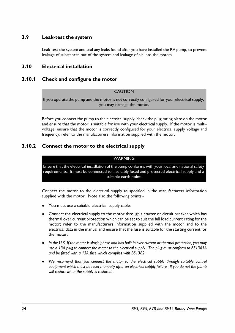
3.9 Leak-test the system
Leak-test the system and seal any leaks found after you have installed the RV pump, to preventleakage of substances out of the system and leakage of air into the system.
3.10 Electrical installation
3.10.1 Check and configure the motor
Before you connect the pump to the electrical supply, check the plug rating plate on the motorand ensure that the motor is suitable for use with your electrical supply. If the motor is multi-voltage, ensure that the motor is correctly configured for your electrical supply voltage andfrequency; refer to the manufacturers information supplied with the motor.
3.10.2 Connect the motor to the electrical supply
Connect the motor to the electrical supply as specified in the manufacturers informationsupplied with the motor. Note also the following points;-
! You must use a suitable electrical supply cable.
! Connect the electrical supply to the motor through a starter or circuit breaker which hasthermal over current protection which can be set to suit the full load current rating for themotor; refer to the manufacturers information supplied with the motor and to theelectrical data in the manual and ensure that the fuse is suitable for the starting current forthe motor.
! In the U.K. If the motor is single phase and has built in over current or thermal protection, you mayuse a 13A plug to connect the motor to the electrical supply. The plug must conform to BS1363Aand be fitted with a 13A fuse which complies with BS1362.
! We recomend that you connect the motor to the electrical supply through suitable controlequipment which must be reset manually after an electrical supply failure. If you do not the pumpwill restart when the supply is restored.
CAUTION
If you operate the pump and the motor is not correctly configured for your electrical supply, you may damage the motor.
WARNING
Ensure that the electrical insatllation of the pump conforms with your local and national safety requirements. It must be connected to a suitably fused and protected electrical supply and a
suitable earth point.
24 RV3, RV5, RV8 and RV12 Rotary Vane Pumps
3.11 Check the direction of rotation
1. Correct direction of rotation is anti clockwise when looking on the motor fan.
2. Watch the motor fan, switch on the supply to the motor for a few seconds, then switch off.
3. If the direction of rotation is incorrect, isolate the motor from the supply and reconfigurethe electrical connections to the motor; refer to the manufacturuers information suppliedwith the motor.
4. Repeat the above check to ensure the direction of rotation is correct.
CAUTION
Ensure that the motor rotates in the correct direction. If it does not the pump and vacuum system will be pressurised. Do not connect the pump to the vacuum system when carrying
out these tests.
RV3, RV5, RV8 and RV12 Rotary Vane Pumps 25
4 OPERATION
4.1 ATEX directive implications
4.1.1 Introduction
This equipment is designed to meet the requirements of Group II Category 3 equipment inaccordance with Directive 94/9/EC of the European Parliament and the Council of 23rd March1994 on the approximation of the laws of the Member States concerning equipment andprotective systems intended for use in potentially explosive atmospheres. (The ATEXDirective)
The ATEX Category 3 applies in respect of potential ignition sources internal to the equipment.An ATEX Category has not been assigned in respect of potential ignition sources on theoutside of the equipment as the equipment has not been designed for use where there is anexternal potentially explosive atmosphere.
There is no potential source of ignition within the pump during normal operation but theremay be potential sources of ignition under conditions of predicted and rare malfunction asdefined in the Directive. Accordingly, although the pump is designed to pump flammablematerials and mixtures, operating procedures should ensure that under all normal andreasonably predicted conditions, these materials and mixtures are not within explosive limits.Category 3 is considered appropriate for the avoidance of ignition in the case of a raremalfunction which allows flammable materials or mixtures to pass through the pump whilewithin their explosive limits.
4.1.2 Flammable/pyrophoric materials
When flammable or pyrophoric materials are present within the equipment you must:
! Not allow air to enter the equipment.
! Ensure the system is leak tight.
! Use an inert gas purge (for example, a nitrogen purge) to dilute any flammable gases orvapours entering the pump inlet, and/or use an inert gas purge to reduce the concentrationof flammable gases or vapours in the pump and in the exhaust pipeline to less than onequarter of the gases' published lower explosive limits (LEL).
! Use an inert gas purge in to the pump gas ballast connection to prevent the condensationof flammable vapours within the pump mechanism and exhaust pipeline.
WARNING
You must obey the instructions and take note of the precautions given below, to ensure that pumped gases do not enter their flammable ranges.
26 RV3, RV5, RV8 and RV12 Rotary Vane Pumps

4.1.3 Gas purges
Switch on the inert gas purge to remove air from the pump and the exhaust pipeline beforethe process starts. Switch off the purge flow at the end of the process only after any remainingflammable gases or vapours have been purged from the pump and exhaust pipeline.
If liquids that produce flammable vapours could be present in the pump foreline, then the inertgas purge to the RV3, RV5, RV8 and RV12 rotary vane pump should be left on all the time thisliquid is present. Flammable liquids could be present in the foreline as a result of condensation,or may be carried over from the process.
When you calculate the flow rate of inert gas required for dilution, consider the maximum flowrate for the flammable gases/vapours that could occur. For example, if a mass flow controlleris used to supply flammable gases to the process, you should assume a flow rate for flammablegases that could arise if the mass flow controller is fully open.
Continually measure the inert gas purge flow rate: if the flow rate falls below that required, youmust stop the flow of flammable gases or vapours into the pump.
Note: We recommend that you obtain and read the Vacuum Pump and Vacuum System Safetymanual (publication number P300-20-000), available from BOC Edwards or your supplier.
4.2 How to use the pump controls
You can use the mode selector (Figure 1, item 11) and the gas-ballast control (Figure 1, item 5)to optimise the performance of the RV pump for your application. The performancecharacteristics of the pump with the different control settings are shown in Tables 1 and 2. Youcan change the position of both the mode selector and the gas-ballast control when the pumpis off or when the pump is operating.
WARNING
If you use inert gas purges to dilute dangerous gases to a safe level, ensure that the RV3, RV5, RV8 and RV12 rotary vane pump is shut down if an inert
gas supply fails.
WARNING
You must obey the instructions and take note of the precautions given below, to ensure that pumped gases do not enter their flammable ranges.
RV3, RV5, RV8 and RV12 Rotary Vane Pumps 27
4.2.1 Mode selector
Note: The pump is supplied with High Vacuum mode " selected. If High Vacuum mode is selectedand you cannot turn the mode selector by hand to select the High Throughput mode, use asuitable tool fitted to the flat part of the mode selector to turn the selector.
The mode selector controls the flow of pressurised oil to the high vacuum stage of the pump(see Section 1.4.1). You can turn the mode selector to one of two positions, as follows:
To select the High Vacuum mode ", turn the mode selector fully clockwise and tighten by hand.When High Vacuum mode is selected, there is a gap of approximately 3 mm between the modeselector and the inner face of the side panel of the pump. Use this mode:
! to achieve ultimate vacuum
! to pump clean gases
! to pump clean condensable vapours.
To select the High Throughput mode ", turn the mode selector fully anticlockwise until ittouches the inner face of the side panel of the pump, then gently tighten by hand. Use thismode:
! for long-term operation with high gas throughput (that is, inlet pressure > 50 mbar)
! to pump dirty condensable vapours
! to decontaminate the oil.
4.2.2 Gas-ballast control
Use the gas-ballast control to change the amount of air (or inert gas) introduced into the lowvacuum stage of the pump (refer to Section 1.4.2). Use of gas-ballast will prevent thecondensation of vapours in the pump; the condensates would contaminate the oil. You canturn the gas-ballast control to select one of three positions, as follows:
To select gas-ballast closed, turn the control to position '0'. Use this setting:
! to achieve ultimate vacuum
! to pump dry gases.
To select low flow gas-ballast, turn the control to position 'I'. Use this setting:
! to pump low concentrations of condensable vapours
! to decontaminate the oil.
28 RV3, RV5, RV8 and RV12 Rotary Vane Pumps
To select high flow gas-ballast, turn the control to position 'II'. Use this setting:
! to pump high concentrations of condensable vapours.
When you use either low flow or high flow gas-ballast, there will be an increased rate of oilloss from the pump. Where possible, we recommend that you select low flow gas-ballast(position 'I') rather than high flow gas-ballast (position 'II') to minimise the loss of oil.
4.3 Start-up procedure
If the oil is contaminated, or if the pump temperature is below 12 °C, or if the electrical supplyvoltage is more than 10% below the lowest voltage specified on the voltage indicator (Figure4, item 4), the pump may operate at a reduced speed for a few minutes. On single-phasepumps, if the pump continues to operate at reduced speed, the motor thermal overload devicewill open and stop the pump. When the motor has cooled, the thermal overload device willreset automatically and the pump will restart.
1. Check that the pump oil-level is between the MAX and MIN marks on the bezel of the oil-level sight-glass; if it is not, refer to Section 5.3.
2. Turn the mode selector fully clockwise to select High Vacuum mode " or fullyanticlockwise to select High Throughput mode ", as required (refer to Section 4.2.1).
3. Turn the gas-ballast control to position '0', 'I' or 'II', as required (refer to Section 4.2.2).
4. Switch on the electrical supply to the pump; on single-phase pumps, use the on/off switch.
5. If you want to achieve ultimate vacuum, to pump condensable vapours or to decontaminatethe pump oil, refer to the procedures in Sections 4.4, 4.5 and 4.6 respectively. Otherwise,open the vacuum system isolation-valve.
4.4 To achieve ultimate vacuum
If the pump does not achieve the performance specified in Section 2, make sure that this is notdue to your system design before you contact your supplier or Edwards for advice. Inparticular, the vapour pressure of all materials used in your vacuum system (including pump oil,see below) must be much lower than the specified ultimate vacuum of the pump. Refer toSection 5.12.2 for a list of possible causes for failure to achieve the specified performance; notehowever that the most common causes are:
! Your pressure measurement technique or gauge head is unsuitable or the gauge head isfaulty.
! You have used an oil other than the recommended oil, and the vapour pressure of the oilis higher than the specified ultimate vacuum of the pump.
WARNING
Ensure that your system design does not allow the exhaust pipeline to be blocked.
RV3, RV5, RV8 and RV12 Rotary Vane Pumps 29

Use the following procedure to achieve ultimate vacuum:
1. Isolate the RV pump from your vacuum system.
2. Turn the mode selector to select High Throughput mode ", set the gas-ballast control tolow flow (position 'I') and operate the pump for at least 1 hour (or overnight) to thoroughlypurge the oil of contaminants.
3. Turn the mode selector to select High Vacuum mode " and close the gas-ballast control(that is, set it to position '0').
4. Open the vacuum system isolation-valve and pump down to ultimate vacuum.
4.5 To pump condensable vapours
Use gas-ballast (gas-ballast control in position 'I' or 'II') when there is a high proportion ofcondensable vapours in the process gases.
1. Close the vacuum system isolation-valve.
2. Turn the mode selector fully clockwise to select High Vacuum mode " or fullyanticlockwise to select High Throughput mode ", as required (refer to Section 4.2.1).
3. Turn the gas-ballast control to high flow (position 'II') and operate the pump for 30 minutesto warm the oil; this will help to prevent vapour condensation in the pump.
4. Set the gas-ballast control to the position required for your application (refer to Section4.2.2 and the data in Tables 1 and 2).
5. Open the vacuum system isolation-valve.
After you have pumped condensable vapours, you can (if necessary) decontaminate the oil: usethe procedure in Section 4.6.
4.6 To decontaminate the oil
The oil in the pump should be clear; if the oil is cloudy or discoloured, it is contaminated withprocess vapours.
1. Look at the condition of the oil in the oil-level sight-glass (Figure 1, item 8). If the oil iscloudy or discoloured, continue with the procedure at Step 2 below.
2. Close the vacuum system isolation-valve.
3. Turn the mode selector fully anticlockwise to select High Throughput mode ". Set thegas-ballast control to low flow (position 'I').
4. Operate the pump until the oil is clear.
30 RV3, RV5, RV8 and RV12 Rotary Vane Pumps

4.7 Unattended operation
The RV pump is designed for unattended operation under the normal operating conditionsspecified in Section 2. However, we recommend that you check the pump at regular intervalsof not more than 14 days, or more frequently if you pump high volumes of gas or vapour.
On single-phase pumps, the motor is protected by an overload device which isolates the pumpfrom the electrical supply when critical temperature or current levels are exceeded. Theoverload device resets automatically when the motor has cooled. When you check the pump,make sure that the pump is not going through a repetitive cycle of thermal overload failuresand automatic resets. If necessary, change the mode selector to High Throughput mode " andreduce the thermal load from the pumped gases, to prevent overheating of the pump.
4.8 Shut-down
We recommend, as described in the procedure below, that you decontaminate the oil beforeyou shut down the pump; this will prevent damage to the pump by the contaminates in the oil.
1. Refer to Section 4.6 and decontaminate the oil, as required.
2. Close the vacuum system isolation-valve (if not already closed).
3. Close gas-ballast (that is, set the gas-ballast control to position '0').
4. On single-phase pumps, use the on/off switch to switch off the pump.
5. Switch off the electrical supply to the pump.
RV3, RV5, RV8 and RV12 Rotary Vane Pumps 31
5 MAINTENANCE
5.1 Safety information
! If your pump is PFPE prepared, refer to Section 8.
! Ensure that maintenance is done by a suitably trained and supervised technician. Obey yourlocal and national safety requirements.
! Ensure that the maintenance technician is familiar with the safety procedures which relateto the pump-oil and the products processed by the pumping system.
! Check that all the required parts are available and of the correct type before you startwork.
! Isolate the pump and other components from the electrical supply so that they cannot beoperated accidentally.
! Allow the pump to cool (so that it is at a safe temperature for skin contact) before youstart maintenance work. Make sure the pump is switched off in case the thermal overloaddevice restarts the pump.
! Do not reuse 'O' rings and seals if they are damaged.
! After maintenance is completed, recheck the direction of pump rotation if the electricalsupply has been disconnected.
! The pump and the pump-oil will be contaminated with the process chemicals that havebeen pumped during operation. Ensure that the pump is decontaminated beforemaintenance and that you take adequate precautions to protect people from the effects ofdangerous substances if contamination has occurred.
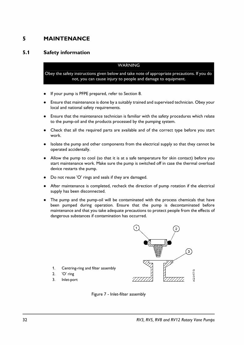
Figure 7 - Inlet-filter assembly
WARNING
Obey the safety instructions given below and take note of appropriate precautions. If you do not, you can cause injury to people and damage to equipment.
1. Centring-ring and filter assembly2. 'O' ring3. Inlet-port
32 RV3, RV5, RV8 and RV12 Rotary Vane Pumps
! Do not touch or inhale the thermal breakdown products of fluorinated materials whichmay be present if the pump has been heated to 310 °C and above. Fluorinated materialsare safe in normal use but can decompose into very dangerous substances (which mayinclude hydrofluoric acid) if they are heated to 310 °C and above. The pump may haveoverheated if it was misused or if it was in a fire. Health and Safety Data sheets forfluorinated materials used in the pump are available on request: contact your supplier orEdwards.
! If neccessary, maintain the motor as specified in the manufacturers information suppliedwith the motor.
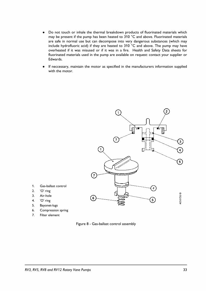
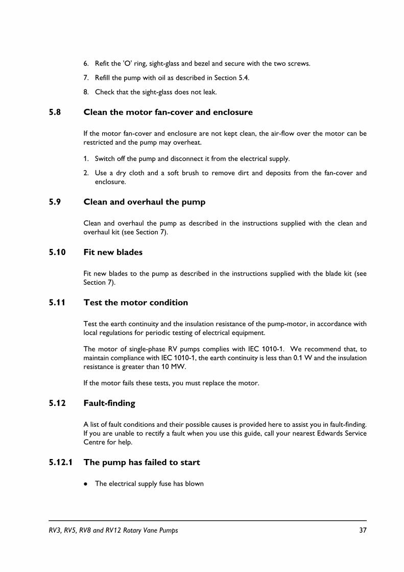
Figure 8 - Gas-ballast control assembly
1. Gas-ballast control2. 'O' ring3. Air-hole4. 'O' ring5. Bayonet-lugs6. Compression spring7. Filter element
RV3, RV5, RV8 and RV12 Rotary Vane Pumps 33

5.2 Maintenance plan
The plan shown in Table 7 details the routine maintenance operations necessary to maintainRV pumps in normal use. Instructions for each operation are given in the section shown.
Table 7 - Maintenance plan
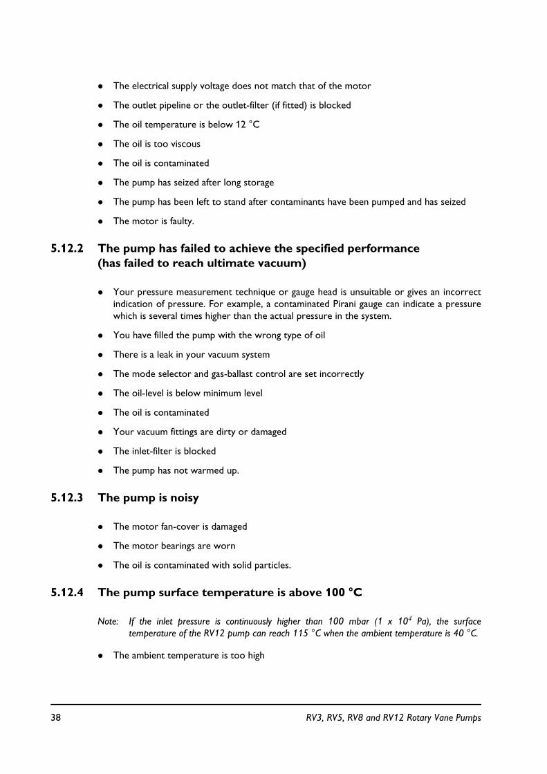
Figure 9 - Sight-glass assembly
Operation Frequency Refer to Section
Check the oil-levelReplace the oilInspect and clean the inlet-filterInspect and clean the gas-ballast controlClean the oil-level sight-glassClean the motor fan-cover and enclosureClean and overhaul the pumpFit new bladesTest the motor condition
MonthlyEvery 3000 hours
YearlyYearlyYearlyYearly
Every 15000 hoursEvery 30000 hoursEvery 15000 hours
5.35.45.55.65.75.85.95.105.11
1. Screws (2 off M6 x 20)2. Bezel3. Sight-glass4. 'O' ring5. Oil-box
34 RV3, RV5, RV8 and RV12 Rotary Vane Pumps

More frequent maintenance may be required if the pump is used to pump corrosive or abrasivegases and vapours, such as solvents, organic substances and acids; in these circumstances, werecommend that you replace the pump seals every year (refer to Section 7 for details ofavailable spares). If necessary, adjust the maintenance plan according to your experience.
When you maintain the RV pump, use Edwards spares and maintenance kits; these contain allof the components necessary to complete maintenance operations successfully. The ItemNumbers of the spares and kits are given in Section 7.
5.3 Check the oil-level
Note: If required, you can check the oil-level while the pump is operating, however you must switchoff the pump and isolate the pump and other components in the pumping system from theelectrical supply before you pour oil into the pump.
Refer to Figure 1 for the items in brackets.
1. Check that the oil-level in the sight-glass (8) is between the MAX and MIN level marks onthe bezel of the sight-glass.
2. If the oil-level is near to or below the MIN level mark, remove one of the filler-plugs (6)and pour more oil into the reservoir until the oil reaches the MAX level mark. If the oil-level goes above the MAX mark, remove the drain-plug (9) and drain the excess oil fromthe pump. Refit the filler-plug.
3. If the oil is contaminated, drain and refill the pump with clean oil as described in Section 5.4.
5.4 Replace the oil
1. Refer to Figure 1. Operate the pump for approximately ten minutes to warm the oil, thenswitch off the pump (this lowers the viscosity of the oil and enables it to be drained fromthe pump more easily).
2. Isolate the pump from your electrical supply and disconnect it from your vacuum system.
3. Remove one of the oil filler-plugs (6).
4. Place a suitable block under the pump-motor to tilt the pump and place a suitable containerunder the drain-plug (9). Remove the drain-plug and allow the oil to drain into thecontainer.
5. If the oil drained from the pump is contaminated, pour clean oil into the filler-hole and allowit to drain out of the pump. Repeat this step until the oil reservoir in the pump has beenthoroughly cleaned.
6. Refit the drain-plug, remove the block and reconnect the pump to your vacuum system.
7. Fill a suitable container with clean oil and pour the oil into the filler hole until the oil-levelreaches the MAX level mark on the bezel of the sight-glass (8).
8. Allow a few minutes for the oil to drain into the pump. If necessary, add more oil. Refitthe filler-plug.
RV3, RV5, RV8 and RV12 Rotary Vane Pumps 35
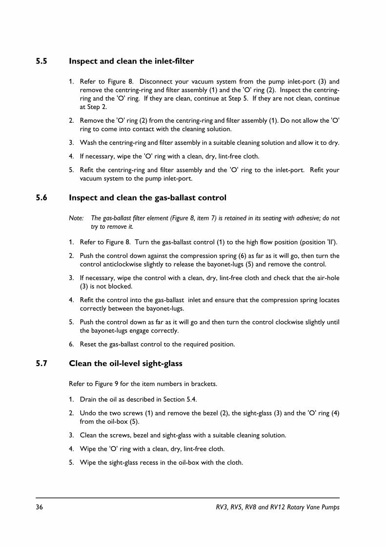
5.5 Inspect and clean the inlet-filter
1. Refer to Figure 8. Disconnect your vacuum system from the pump inlet-port (3) andremove the centring-ring and filter assembly (1) and the 'O' ring (2). Inspect the centring-ring and the 'O' ring. If they are clean, continue at Step 5. If they are not clean, continueat Step 2.
2. Remove the 'O' ring (2) from the centring-ring and filter assembly (1). Do not allow the 'O'ring to come into contact with the cleaning solution.
3. Wash the centring-ring and filter assembly in a suitable cleaning solution and allow it to dry.
4. If necessary, wipe the 'O' ring with a clean, dry, lint-free cloth.
5. Refit the centring-ring and filter assembly and the 'O' ring to the inlet-port. Refit yourvacuum system to the pump inlet-port.
5.6 Inspect and clean the gas-ballast control
Note: The gas-ballast filter element (Figure 8, item 7) is retained in its seating with adhesive; do nottry to remove it.
1. Refer to Figure 8. Turn the gas-ballast control (1) to the high flow position (position 'II').
2. Push the control down against the compression spring (6) as far as it will go, then turn thecontrol anticlockwise slightly to release the bayonet-lugs (5) and remove the control.
3. If necessary, wipe the control with a clean, dry, lint-free cloth and check that the air-hole(3) is not blocked.
4. Refit the control into the gas-ballast inlet and ensure that the compression spring locatescorrectly between the bayonet-lugs.
5. Push the control down as far as it will go and then turn the control clockwise slightly untilthe bayonet-lugs engage correctly.
6. Reset the gas-ballast control to the required position.
5.7 Clean the oil-level sight-glass
Refer to Figure 9 for the item numbers in brackets.
1. Drain the oil as described in Section 5.4.
2. Undo the two screws (1) and remove the bezel (2), the sight-glass (3) and the 'O' ring (4)from the oil-box (5).
3. Clean the screws, bezel and sight-glass with a suitable cleaning solution.
4. Wipe the 'O' ring with a clean, dry, lint-free cloth.
5. Wipe the sight-glass recess in the oil-box with the cloth.
36 RV3, RV5, RV8 and RV12 Rotary Vane Pumps
6. Refit the 'O' ring, sight-glass and bezel and secure with the two screws.
7. Refill the pump with oil as described in Section 5.4.
8. Check that the sight-glass does not leak.
5.8 Clean the motor fan-cover and enclosure
If the motor fan-cover and enclosure are not kept clean, the air-flow over the motor can berestricted and the pump may overheat.
1. Switch off the pump and disconnect it from the electrical supply.
2. Use a dry cloth and a soft brush to remove dirt and deposits from the fan-cover andenclosure.
5.9 Clean and overhaul the pump
Clean and overhaul the pump as described in the instructions supplied with the clean andoverhaul kit (see Section 7).
5.10 Fit new blades
Fit new blades to the pump as described in the instructions supplied with the blade kit (seeSection 7).
5.11 Test the motor condition
Test the earth continuity and the insulation resistance of the pump-motor, in accordance withlocal regulations for periodic testing of electrical equipment.
The motor of single-phase RV pumps complies with IEC 1010-1. We recommend that, tomaintain compliance with IEC 1010-1, the earth continuity is less than 0.1 W and the insulationresistance is greater than 10 MW.
If the motor fails these tests, you must replace the motor.
5.12 Fault-finding
A list of fault conditions and their possible causes is provided here to assist you in fault-finding.If you are unable to rectify a fault when you use this guide, call your nearest Edwards ServiceCentre for help.
5.12.1 The pump has failed to start
! The electrical supply fuse has blown
RV3, RV5, RV8 and RV12 Rotary Vane Pumps 37
! The electrical supply voltage does not match that of the motor
! The outlet pipeline or the outlet-filter (if fitted) is blocked
! The oil temperature is below 12 °C
! The oil is too viscous
! The oil is contaminated
! The pump has seized after long storage
! The pump has been left to stand after contaminants have been pumped and has seized
! The motor is faulty.
5.12.2 The pump has failed to achieve the specified performance (has failed to reach ultimate vacuum)
! Your pressure measurement technique or gauge head is unsuitable or gives an incorrectindication of pressure. For example, a contaminated Pirani gauge can indicate a pressurewhich is several times higher than the actual pressure in the system.
! You have filled the pump with the wrong type of oil
! There is a leak in your vacuum system
! The mode selector and gas-ballast control are set incorrectly
! The oil-level is below minimum level
! The oil is contaminated
! Your vacuum fittings are dirty or damaged
! The inlet-filter is blocked
! The pump has not warmed up.
5.12.3 The pump is noisy
! The motor fan-cover is damaged
! The motor bearings are worn
! The oil is contaminated with solid particles.
5.12.4 The pump surface temperature is above 100 °C
Note: If the inlet pressure is continuously higher than 100 mbar (1 x 10⁴ Pa), the surfacetemperature of the RV12 pump can reach 115 °C when the ambient temperature is 40 °C.
! The ambient temperature is too high
38 RV3, RV5, RV8 and RV12 Rotary Vane Pumps

! The cooling-air supply is insufficient or is too hot
! The electrical supply voltage is too high
! The outlet-filter or the outlet pipeline is blocked
! The oil-level is below minimum level
! You have filled the pump with the wrong type of oil
! The oil is contaminated
! The process gas is too hot or the throughput is too high.
5.12.5 The vacuum is not fully maintained after the pump is switched off
! The gas-ballast control is open (that is, in position 'I' or 'II')
! The inlet valve-pad is damaged
! The inlet valve has not closed.
5.12.6 The pumping speed is poor
! The connecting pipelines are too small in diameter
! The connecting pipelines are too long
! The inlet-filter is blocked.
5.12.7 There is an external oil leak
! The outer shaft-seal is worn or damaged
! The oil-box gaskets have deteriorated
! There is an oil leak from the gas-ballast control
! There is an oil leak from the drain-plug
! There is an oil leak from the sight-glass
RV3, RV5, RV8 and RV12 Rotary Vane Pumps 39

6 STORAGE AND DISPOSAL
6.1 Storage
Note: If you will store a new pump in conditions of high humidity, remove the pump from itscardboard packaging box; dispose of the box (refer to Section 6.2).
Use the following procedure to store the pump:
1. Shut-down the pump as described in Section 4.
2. Disconnect the pump from the electrical supply.
3. Purge your vacuum system and the pump with dry nitrogen and disconnect the pump fromyour vacuum system.
4. Replace the oil as described in Section 5.4.
5. Place and secure protective covers over the inlet and outlet-ports.
6. Store the pump in cool, dry conditions until required for use. When required, prepare andinstall the pump as described in Section 3. If the pump has been stored for more than ayear, before you install the pump you must clean and overhaul it as described in theinstructions supplied with the clean and overhaul kit.
6.2 Disposal
Dispose of the pump and any components removed from it safely in accordance with all localand national safety and environmental requirements.
Particular care must be taken with components and waste oil which have been contaminatedwith dangerous process substances.
Do not incinerate fluoroelastomer seals and 'O' rings.
CAUTION
Observe the storage temperature limits stated in Section 2. Storage below -30 °C will permanently damage the pump seals.
40 RV3, RV5, RV8 and RV12 Rotary Vane Pumps
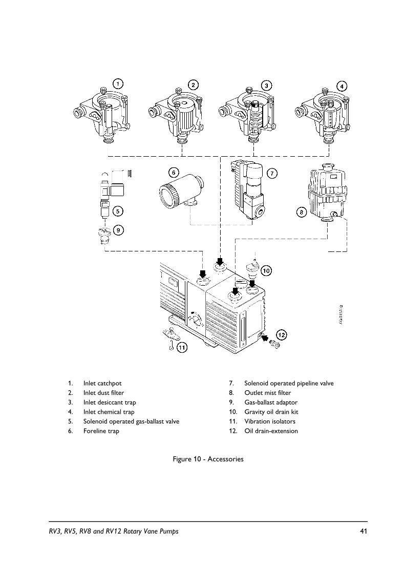
Figure 10 - Accessories
1. Inlet catchpot2. Inlet dust filter3. Inlet desiccant trap4. Inlet chemical trap5. Solenoid operated gas-ballast valve6. Foreline trap
7. Solenoid operated pipeline valve 8. Outlet mist filter9. Gas-ballast adaptor10. Gravity oil drain kit11. Vibration isolators12. Oil drain-extension
RV3, RV5, RV8 and RV12 Rotary Vane Pumps 41

7 SERVICE, SPARES AND ACCESSORIES
7.1 Introduction
Edwards products, spares and accessories are available from Edwards companies in Belgium,Brazil, Canada, France, Germany, Hong Kong, Italy, Japan, Korea, Switzerland, United Kingdom,U.S.A and a world-wide network of distributors. The majority of these centres employ ServiceEngineers who have undergone comprehensive Edwards training courses.
Order spare parts and accessories from your nearest Edwards company or distributor. Whenyou order, state for each part required:
! Model and Item Number of your equipment
! Serial number
! Item Number and description of part.
7.2 Service
Edwards products are supported by a world-wide network of Edwards Service Centres. EachService Centre offers a wide range of options including: equipment decontamination; serviceexchange; repair; rebuild and testing to factory specifications. Equipment which has beenserviced, repaired or rebuilt is returned with a full warranty.
Your local Service Centre can also provide Edwards engineers to support on-site maintenance,service or repair of your equipment.
For more information about service options, contact your nearest Service Centre or otherEdwards company.
42 RV3, RV5, RV8 and RV12 Rotary Vane Pumps

7.3 Spares
Table 8 - Spares and Accessories
Product
Hydrocarbon VariantsPart Number
PFPE VariantsPart Number
Edwards oil 1L Ultragrade 19 H110-25-015
(1kg) Fomblin 06/6 H113-06-019
Edwards oil 4L Ultragrade 19 H110-25-013
(5kg) Fomblin 06/6 H113-06-020
Clean and overhaul kit (Standard) A652-01-131 A652-01-131
RV3 Blade kit A652-01-130 A652-01-130
RV5 Blade kit A653-01-130 A653-01-130
RV8 Blade kit A654-01-130 A654-01-130
RV12 Blade kit A655-01-130 A655-01-130
RV3 Cartridge Kit A652-01-032 A652-09-032
RV5 Cartridge Kit A653-01-032 A653-09-032
RV8 Cartridge Kit A654-01-032 A654-09-032
RV12 Cartridge Kit A655-01-032 A655-09-032
Inlet-valve kit A652-01-036 A652-01-036
Motor Starting Relay Kit A505-74-000 A505-74-000
Outer Shaft-Seal Kit A652-01-134 A652-01-134
Rotor Sleeve Kit A652-01-136 A652-09-136
RV3/RV5 Motor Kit (Europe/USA) 50/60 Hz, 250/300 W, 1 phase, 110-120/220-240 V
A652-99-000 A652-99-000
RV8/RV12Motor Kit (Europe/USA) 50/60 Hz, 450/550 W, 1 phase, 110-120/220-240 V
A654-99-000 A654-99-000
RV3/RV5 Motor Kit (Japan) 50/60 Hz, 250/300 W, 1 phase, 100/200 V
A652-98-000 A652-98-000
RV8/RV12 Motor Kit (Japan) 50/60 Hz, 450/550 W, 1 phase, 100/200 V
A654-98-000 A654-98-000
RV3/RV5 Motor Kit (Europe/USA/Japan 50/60 Hz, 250/300 W, 3 phase, 200-230/380-460 V
A652-97-000 A652-97-000
RV8/RV12 Motor Kit (Europe/USA/Japan) 50/60 Hz, 450/550 W, 3 phase, 200-230/380-460 V
A654-97-000 A654-97-000
Clean and Overhaul Kit (Nitrile) A652-01-137
RV3, RV5, RV8 and RV12 Rotary Vane Pumps 43
7.4 Accessories
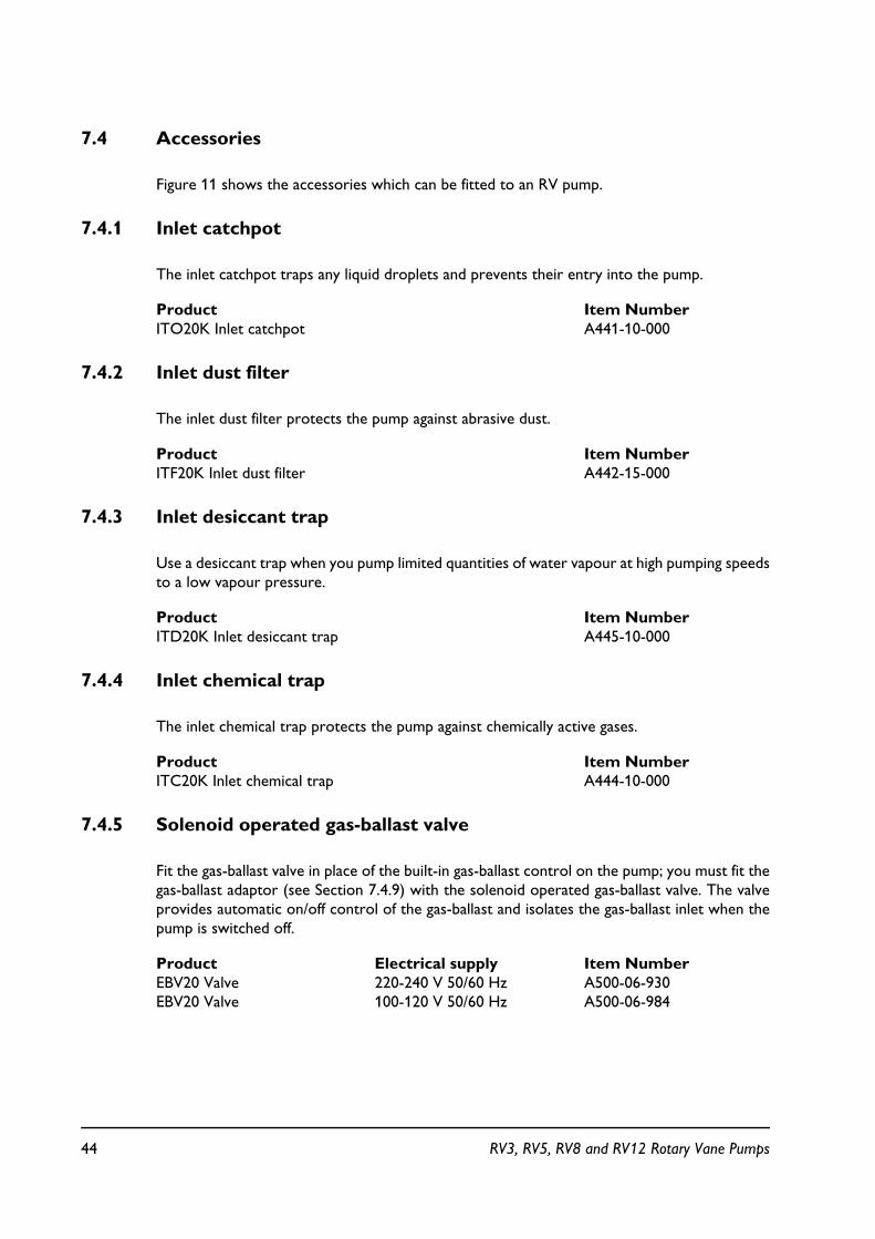
Figure 11 shows the accessories which can be fitted to an RV pump.
7.4.1 Inlet catchpot
The inlet catchpot traps any liquid droplets and prevents their entry into the pump.
Product Item NumberITO20K Inlet catchpot A441-10-000
7.4.2 Inlet dust filter
The inlet dust filter protects the pump against abrasive dust.
Product Item NumberITF20K Inlet dust filter A442-15-000
7.4.3 Inlet desiccant trap
Use a desiccant trap when you pump limited quantities of water vapour at high pumping speedsto a low vapour pressure.
Product Item NumberITD20K Inlet desiccant trap A445-10-000
7.4.4 Inlet chemical trap
The inlet chemical trap protects the pump against chemically active gases.
Product Item NumberITC20K Inlet chemical trap A444-10-000
7.4.5 Solenoid operated gas-ballast valve
Fit the gas-ballast valve in place of the built-in gas-ballast control on the pump; you must fit thegas-ballast adaptor (see Section 7.4.9) with the solenoid operated gas-ballast valve. The valveprovides automatic on/off control of the gas-ballast and isolates the gas-ballast inlet when thepump is switched off.
Product Electrical supply Item NumberEBV20 Valve 220-240 V 50/60 Hz A500-06-930EBV20 Valve 100-120 V 50/60 Hz A500-06-984
44 RV3, RV5, RV8 and RV12 Rotary Vane Pumps

7.4.6 Foreline trap
Use a foreline trap on a clean pumping system to prevent back-migration of pump-oil vapourinto your vacuum system.
Product Item NumberFL20K Foreline trap A133-05-000
7.4.7 Solenoid operated pipeline valve
Fit the pipeline valve between your vacuum system and the pump-inlet to provide additionalsystem protection when the pump is switched off.
Product Electrical supply Item NumberAluminium Stainless steel
PV25EK Valve 220-240 V 50/60 Hz C413-01-000 C413-02-000PV25EK Valve 110-127 V 50/60 Hz C413-03-000 C413-04-000
7.4.8 Outlet mist filter
The outlet mist filter separates and traps oil droplets in the pump outlet to prevent oil mistdischarge.
Product Item NumberEMF10 Outlet mist filter A462-26-000EMF20 Outlet mist filter A462-29-000
7.4.9 Gas-ballast adaptor
Fit the gas-ballast adaptor in place of the gas-ballast control on the pump. The adaptor allowsyou to fit a solenoid operated gas-ballast valve or a controlled supply of inert gas to the pump.
Product Item NumberGas-ballast adaptor A505-02-000
7.4.10 Gravity oil drain kit
Fit the oil drain kit between the drain port of the outlet mist filter and the oil filler-plug on thepump. When the kit is fitted, oil will be returned from the mist filter to the pump when thepump is switched off or when the gas-ballast control is closed (in the '0' position) and there isno process gas being pumped.
Product Item NumberGravity oil drain kit A505-01-000
RV3, RV5, RV8 and RV12 Rotary Vane Pumps 45
7.4.11 Vibration isolators
Vibration isolators reduce vibration and noise when the pump is floor or frame mounted andhelp to reduce strain when the mounting area is uneven.
Product Item NumberVibration isolators (pack of four) A248-01-404
7.4.12 Oil drain-extension
Fit the oil drain-extension between the oil drain port on the pump and the oil drain-plug tomake the drainage of oil from the pump easier.
Product Item NumberOil drain-extension A505-03-000
7.4.13 Exhaust nozzle kit
The exhaust nozzle replaces the outlet flange. Use the exhaust nozzle to connect the pumpoutlet to 12 mm internal diameter plastic hose.
Product Item NumberExhaust nozzle kit A505-09-000
46 RV3, RV5, RV8 and RV12 Rotary Vane Pumps
RV3, RV5, RV8 and RV12 Rotary Vane Pumps 47
8 ROTARY VACUUM PUMP PREPARED FOR USES WITH PFPE OILS
8.1 Summary
The pump is prepared for use with BOC Edwards PFPE mechanical pump oils, (such as FomblinYVAC 06/6 and Krytox 1506) and is intended for use when pumping high concentrates ofoxygen.
8.2 Installation
When you fill the pump with oil, use a suitable BOC Edwards PFPE oil. Ignore any furthermention of BOC Edwards Oils stated in this manual.
8.3 Maintenance
Note! Fomblin oil is difficult to seal, and it is advised that a regular check must be performedfor oil leaks, especially round shaft seals.
8.4 System Safety
Refer to EHVI Publication No P300-20-0000. (Vacuum Pump & Vacuum System Safety)
WARNING
PFPE prepared pumps allow pumping of high concentrates of oxygen, but are not recommended for pumping hazardous materials.
CAUTION
Never use hydrocarbon lubricants in a PFPE prepared pump.
WARNING
Do not touch the thermal breakdown products of fluorinated materials which may PFPE present if the pump has been heated to 260 °C and above. These breakdown products are very dangerous. Fluorinated materials in the pump include the seals, the RT15 grease and
your oil.
CAUTION
Care must be taken after a pump malfunction, in case the oil has been overheated.
9 BARE SHAFT PUMPS
9.1 Description
Two types of bare shaft pump are available;-
! To suit an IEC72-1 motor with an (IMB14) FT85 face mounting and 14 mm diameter shaft.
! To suit a NEMA 56C motor with a 5/8" diameter shaft.
The new motor must have an adequate power rating for use with the RV pump, refer to thepump electrical data section in the manual.
Note: Some of the standard performance specifications may vary, depending on the type of motorfitted.
9.2 Fit the new motor to the pump
Refer to Figure 11. Use the four screws (455) to fit the motor support (453) to the motor.
Use the two screws (422) to fit the lifting plate (413), then fit the lifting plate cover (414).
Fit the fan ducting sheet (409).
Ensure that key "B" is in place on the motor shaft, then push the fan (410) onto the shaft.Ensure that the end of the shaft aligns with the bottom of the cavity in the fan and that the backof the fan is 2,5 mm from the ducting sheet. Secure the fan to the shaft with the screw (454).Tighten the screw to a torque between 7 and 9 Nm.
Use a suitable lubricant on the coupling element (411) then fit the element to the coupling hub.Align the coupling element in the hub with the coupling in the fan and fit the motor to the pump.Secure the motor with the four screws (421). Tighten the screws to a torque of between 10and 12 Nm. The gap between the coupling faces must be 2 mm or less; adjust the position ofthe coupling hub on the pump shaft to acheive this dimension.
48 RV3, RV5, RV8 and RV12 Rotary Vane Pumps
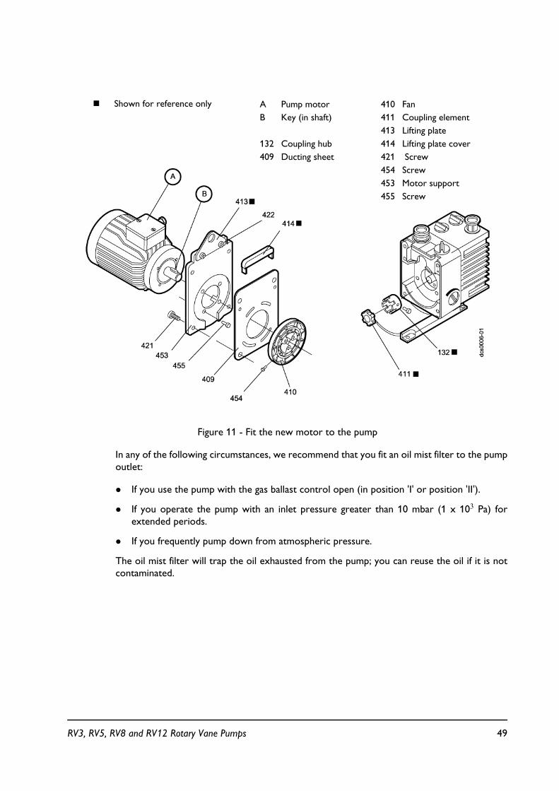
Figure 11 - Fit the new motor to the pump
In any of the following circumstances, we recommend that you fit an oil mist filter to the pumpoutlet:
! If you use the pump with the gas ballast control open (in position 'I' or position 'II').
! If you operate the pump with an inlet pressure greater than 10 mbar (1 x 10³ Pa) forextended periods.
! If you frequently pump down from atmospheric pressure.
The oil mist filter will trap the oil exhausted from the pump; you can reuse the oil if it is notcontaminated.
# Shown for reference only A Pump motorB Key (in shaft)
132 Coupling hub409 Ducting sheet
410 Fan411 Coupling element413 Lifting plate 414 Lifting plate cover 421 Screw454 Screw453 Motor support455 Screw
RV3, RV5, RV8 and RV12 Rotary Vane Pumps 49

50 RV3, RV5, RV8 and RV12 Rotary Vane Pumps
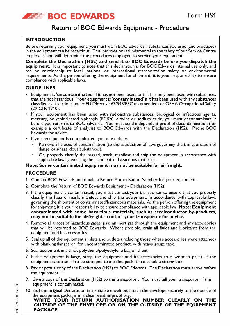
Return of BOC Edwards Equipment - Procedure
Form HS1
INTRODUCTIONBefore returning your equipment, you must warn BOC Edwards if substances you used (and produced)in the equipment can be hazardous. This information is fundamental to the safety of our Service Centreemployees and will determine the procedures employed to service your equipment.Complete the Declaration (HS2) and send it to BOC Edwards before you dispatch theequipment. It is important to note that this declaration is for BOC Edwards internal use only, andhas no relationship to local, national or international transportation safety or environmentalrequirements. As the person offering the equipment for shipment, it is your responsibility to ensurecompliance with applicable laws.
GUIDELINES• Equipment is 'uncontaminated' if it has not been used, or if it has only been used with substances
that are not hazardous. Your equipment is 'contaminated' if it has been used with any substancesclassified as hazardous under EU Directive 67/548/EEC (as amended) or OSHA Occupational Safety(29 CFR 1910).
• If your equipment has been used with radioactive substances, biological or infectious agents,mercury, polychlorinated biphenyls (PCB’s), dioxins or sodium azide, you must decontaminate itbefore you return it to BOC Edwards. You must send independent proof of decontamination (forexample a certificate of analysis) to BOC Edwards with the Declaration (HS2). Phone BOCEdwards for advice.
• If your equipment is contaminated, you must either:• Remove all traces of contamination (to the satisfaction of laws governing the transportation of
dangerous/hazardous substances).• Or, properly classify the hazard, mark, manifest and ship the equipment in accordance with
applicable laws governing the shipment of hazardous materials.Note: Some contaminated equipment may not be suitable for airfreight.
PROCEDURE1. Contact BOC Edwards and obtain a Return Authorisation Number for your equipment.2. Complete the Return of BOC Edwards Equipment - Declaration (HS2).3. If the equipment is contaminated, you must contact your transporter to ensure that you properly
classify the hazard, mark, manifest and ship the equipment, in accordance with applicable lawsgoverning the shipment of contaminated/hazardous materials. As the person offering the equipmentfor shipment, it is your responsibility to ensure compliance with applicable law. Note: Equipmentcontaminated with some hazardous materials, such as semiconductor by-products,may not be suitable for airfreight - contact your transporter for advice.
4. Remove all traces of hazardous gases: pass an inert gas through the equipment and any accessoriesthat will be returned to BOC Edwards. Where possible, drain all fluids and lubricants from theequipment and its accessories.
5. Seal up all of the equipment's inlets and outlets (including those where accessories were attached)with blanking flanges or, for uncontaminated product, with heavy gauge tape.
6. Seal equipment in a thick polythene/polyethylene bag or sheet.7. If the equipment is large, strap the equipment and its accessories to a wooden pallet. If the
equipment is too small to be strapped to a pallet, pack it in a suitable strong box.8. Fax or post a copy of the Declaration (HS2) to BOC Edwards. The Declaration must arrive before
the equipment.9. Give a copy of the Declaration (HS2) to the transporter. You must tell your transporter if the
equipment is contaminated.10. Seal the original Declaration in a suitable envelope: attach the envelope securely to the outside of
the equipment package, in a clear weatherproof bag.WRITE YOUR RETURN AUTHORISATION NUMBER CLEARLY ON THEOUTSIDE OF THE ENVELOPE OR ON THE OUTSIDE OF THE EQUIPMENTPACKAGE.
�����������������
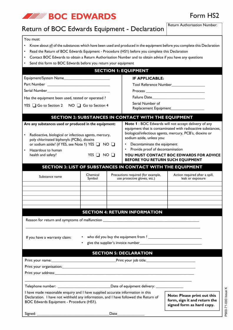
Return of BOC Edwards Equipment - Declaration
Form HS2
You must:
• Know about all of the substances which have been used and produced in the equipment before you complete this Declaration
• Read the Return of BOC Edwards Equipment - Procedure (HS1) before you complete this Declaration
• Contact BOC Edwards to obtain a Return Authorisation Number and to obtain advice if you have any questions
• Send this form to BOC Edwards before you return your equipment
Return Authorisation Number:
Equipment/System Name_________________________
Part Number _________________________________
Serial Number_________________________________
Has the equipment been used, tested or operated ?
YES � Go to Section 2 NO � Go to Section 4
IF APPLICABLE:
Tool Reference Number_________________
Process ______________________________
Failure Date___________________________
Serial Number ofReplacement Equipment_________________
Are any substances used or produced in the equipment:
• Radioactive, biological or infectious agents, mercury, poly chlorinated biphenyls (PCBs), dioxins or sodium azide? (if YES, see Note 1) YES � NO �
• Hazardous to humanhealth and safety? YES � NO �
Note 1 : BOC Edwards will not accept delivery of any equipment that is contaminated with radioactive substances, biological/infectious agents, mercury, PCB’s, dioxins or sodium azide, unless you:
• Decontaminate the equipment• Provide proof of decontamination
YOU MUST CONTACT BOC EDWARDS FOR ADVICE BEFORE YOU RETURN SUCH EQUIPMENT
Print your name:_________________________________Print your job title:_________________________
Print your organisation:____________________________________________________________________
Print your address:_______________________________________________________________________
_______________________________________________________________________Telephone number: ___________________________Date of equipment delivery: ______________
I have made reasonable enquiry and I have supplied accurate information in thisDeclaration. I have not withheld any information, and I have followed the Return ofBOC Edwards Equipment - Procedure (HS1).
Signed: _____________________________________Date______________
• who did you buy the equipment from ? _____________________________
• give the supplier’s invoice number_________________________________If you have a warranty claim:
Substance name ChemicalSymbol
Precautions required (for example,use protective gloves, etc.)
Action required after a spill,leak or exposure
Note: Please print out this form, sign it and return the signed form as hard copy.
SECTION 1: EQUIPMENT
SECTION 2: SUBSTANCES IN CONTACT WITH THE EQUIPMENT
SECTION 3: LIST OF SUBSTANCES IN CONTACT WITH THE EQUIPMENT
SECTION 4: RETURN INFORMATION
SECTION 5: DECLARATION
�����������������
Reason for return and symptoms of malfunction _________________________________________________
_________________________________________________________________________________

nt
This page inte ionally blank.
UNITED KINGDOM
CORPORATE HEADQUARTERSBOC EDWARDS Manor RoyalCrawleyWest Sussex RH10 9LWTel +(44) 1293 528844Fax +(44) 1293 533453
BOC EDWARDSWingates Industrial EstateGreat Bank RoadWesthoughton, BoltonLancashireBL5 3SLTel +(44) 1942 652652Fax +(44) 1942 652651
AMERICA (USA)
USA HEADQUARTERSBOC EDWARDSOne Edwards Park301 Ballardvale StreetWilmington, MA 01887Tel +(1) 978 658 5410Toll free (USA only) 1 800 848 9800Fax +(1) 978 658 7969
3901 Burton DriveSanta Clara, CA 95054Tel +(1) 408 496 1177Fax +(1) 408 496 1188
1810 West Drake DriveSuite 101Tempe, AZ 85283Tel +(1) 480 777 7007Fax +(1) 480 777 2244
11701 Stonehollow DriveSuite 100Austin, TX 78758Tel +(1) 512 491 6622Fax +(1) 512 491 0629
3501 Island AvenuePhiladelphia, PA 19153Tel +(1) 215 365 8653Fax +(1) 978 753 6846
BELGIUM
BOC EDWARDSBergensesteenweg 709B1600 Sint-Pieters-LeeuwBrusselsTel +(32) 2 363 0030Fax +(32) 2 363 0064
BRAZIL
BOC DO BRASIL LTDADIVISÃO EDWARDS ALTO VACORua Bernado Wrona 22202710 São Paulo-SPTel +(55) 11 3952 5000Fax +(55) 11 3965 2766
CANADA
BOC EDWARDS5975 Falbourne StreetMississauga, Ontario L5R3W6CanadaTel +(1) 905 501 2558Fax +(1) 905 501 1632
12055 Cote de LiesseDorval, Quebec H9P1B4CanadaTel +(1) 514 631 3501Fax +(1) 514 631 3502
CHINA
BOC TRADING (SHANGHAI) CO. LTD.23 Fu Te Road (N)Wai Gao Qiao Free Trade ZonePudongShanghai, 200131PRC ChinaTel +(86 21) 5866 9618Fax +(86 21) 5866 9993
FRANCE
BOC EDWARDS125 Avenue Louis Roche92238 Gennevilliers, CedexParisTel +(33) 1 47 98 24 01Fax +(33) 1 47 98 44 54
GERMANY
BOC EDWARDSAmmerthalstraße 3685551 KirchheimMunichTel +(49) 89 99 19 18 0Fax +(49) 89 99 19 18 99
HONG KONG S.A.R.
BOC EDWARDS (ASIA)12 Chun Yat StreetTseung Kwan O Industrial EstateTseung Kwan O, KowloonHong Kong S.A.R.Tel +(852) 2372 2640Fax +(852) 2796 9095
INDIA
BOC EDWARDSDIVIN. OF BOC INDIA LIMITED203 Surya Kiran Building19 Kasturba Gandhi MargNew Delhi - 110 001IndiaTel +(91) 11 851 0065Fax +(91) 11 851 0245
ISRAEL
EDWARDS ISRAEL VACUUM LTD.5 Habarzel BlvdGat 2000 Industrial ZoneQiryat Gat 82000Tel +(972) 8 681 0633Fax +(972) 8 681 0640
ITALY
BOC EDWARDSVia Carpaccio 3520090 Trezzano sul NaviglioMilanTel +(39) 02 48 4471Fax +(39) 02 48 401638
JAPAN
HEADQUARTERSBOC EDWARDSShuwa Shiba Park Building A-3F2-4-1 Shibakoen Minato-kuTokyo, 105-0011Tel +(81) (0) 3 5470 6530Fax +(81) (0) 3 5470 6521
KOREA
HEADQUARTERSSONGWON EDWARDS LTD.5th FL. Daewoo Engineering Bldg.Soonae-dongBundang-gu, Sungnam CityKyungki-do, KoreaTel +(82) 31 716 7070Fax +(82) 31 738 1001-3
FACTORY & GVSONGWON EDWARDS LTD.625-7 Upsong-dongChunan CityChungchong Nam-doKoreaTel +(82) 41 621 7070Fax +(82) 41 621 7700
SINGAPORE
BOC EDWARDS (ASIA)42 Loyang DriveLoyang Industrial EstateSingapore 508962Tel +(65) 6546 8408Fax +(65) 6546 8407
TAIWAN, R.O.C.
EDWARDS TECHNOLOGIES LIMITEDNo. 434 Chung hua RoadToufen Town, Miaoli CountyTaiwan ROCTel +(886) 37 611422Fax +(886) 37 611401
http://[email protected]
PLEASE CONTACT ANY OF THESE COMPANIES FOR DETAILS OF OTHER SALES AND SERVICE CENTRES IN YOUR AREA.BOC Edwards is part of BOC Limited. BOC Edwards and the stripe symbol are trade marks of The BOC Group.© BOC Edwards 2003
Produced by Technical Publicity [email protected]
� ��� ���������������������