s a two-story high rise 10
TRANSCRIPT

1 Airport in Linear Perspective 8
S A Two-Story High Rise 10
8 197" Architectural A wards 01 Excelknce U

MIJDERN CIJNSTRUCnlJN Published by
American Institute of Steel Construction 1221 Avenue of the Americas New York, NY. 10020
o,.Ple ....
Van W. Coddington, President D. B. Hughes,
First Vice President George W. Hall,
Second Vice President Robert P. Stupp, Treasurer John K. Edmonds,
Executive Vice President Leslie H. Gillette,
Assistant Executive Vice President William W. Lanigan,
Secretary and General Counsel
• DITONtAL STA""
Daniel Farb, Director of Publications Mary Anne Stockwell, Editor
... OIONAL o,.,.,le ••
Atlanta, Georgia Birmingham, Alabama Boston, Massachusetts Chicago, Illinois Cleveland, Ohio Columbus, Ohio Dallas, Texas Denver, Colorado Detroit, Michigan Charlotte, North Carolina Hartford, Connecticut Houston, Texas los Angeles, California Memphis, Tennessee Milwaukee, Wisconsin Minneapolis, Minnesota New York, New York Oklahoma City, Oklahoma Omaha, Nebraska Philadelphia, Pennsylvania Pittsburgh, Pennsylvania St. Louis, Missouri San Francisco. California Seattle, Washington Syracuse, New York Washington, District of Columbia
VOLUME XIV I NUMBER 4 1 FOURTH QUARTER 1974
CONTENTS
Airport in Linear Perspective Steel Trusses Support Exchange A Two-Story High Rise Conversion to Steel Frame Saved Time and Money 1974 Architectural Awards of Excellence
SIMPLIFIED STEEL DESIGN-A NEW LECTURE SERIES
8 8
10 12 14
PrMtical steel design by practical methods is the theme of this new series of six lectures that will be presented in major cities throughout the United States. Empha.~is is on the actual design of beams, columns, and connectiolls 1tlilizing many new design aids not available in the AI SC Manual. Basic theory is presented as bMkground for the methods and techniques med in the design examples.
•
Since the previous A/SC lecture series Structural Steel De- • sign was presented in 1971, several supplements to the A/SC Specification have been published and many valuable new de-sign aids have been developed. The new Simplified Steel De-sign series updates and modifies the previcnUl series to reflect this new material.
Each registrant will receive a 100-page compilation of design aids and design examples to be used throughout the lectures. This reference will also prove valuable to the practicing engineer in his everyday work.
Contact your local A/SC regional engineer for time, place, and details of the lectures to be presented in your area.
1975 AISC NATIONAL ENGINEERING CONFERENCE
Leading authorities in the fields of steel design, research and C&nstruction will meet in St. Louis on April SO through May 2 to exchange ideas and information. The engineer or architect who wishes to keep informed about the continuing developments in these fields will find this conference a valuable and exciting experience.
An out8tanding group of speakers will discuss a wide variety of t&pics, such as landmark projects in steel, duigning for motion, and new developments in the design and analysis of structural steel. As a special feature, the winner of the 1975 T. R. Riggin)1 Lectureship Award will make an oral presenta,. ~~~~~ •
Contact A/SC, 1221 Avenue of the Americas, New York, N. Y. 10020 for information about registration.

AIRPORT
in
LINEAR
PERSPECTIVE
• FOURTH QUARTER 1974
The recently completed Greater Cincinnati Airport marks a break with traditional airport terminal design. The architects had little choice but to depart from the conventional approach when asked to come up with a functional , aesthetically pleasing complex that would relieve the congestion at the existing facilities - at half the price and half the cost of a comparable airport terminal.
Design Through Innovation The design process began when in
put from the Airport Board and the airline industry was analyzed from an operational standpoint. The data revealed that most Cincinnati airport traffic involved passenger departures and arrivals, rather than inter-airline transfers for continuation. This fact, coupled with the requirement for maximum future expansion potential based on land availability, led to an individual unit terminal approach.

Airport terminals generally center on a vertically separated highway system, but the high cost of elevated roadway construction dictated an alternate approach. The solution comprised a horizontal separation of the Term inal/Concourse and the Baggage Claim area via a roadway system at grade level, connected by an enclosed pedestrian bridge at the upper level. This arrangement led to the favorable situation of actually having the Baggage Claim building directly in the parking lot.
Ticketing and baggage checking facilities in both the Terminal and Bag· gage Claim buildings allow for quick check-in service for passengers, whether parking at the airport or arriving by commercial transportation . Passengers
arriving in Cincinnati find commercial transportation or curbside pick-up available at the Baggage Claim building.
One Large Holdroom Another breakthrough in airport ter
minal design at the Greater Cincinnati Airport is the treatment of passenger holdrooms. Traditionally, individual boarding gate passenger holdrooms flank the Concourse. However, an indepth analysis revealed that actual usage of these spaces was cycl ical, thereby wasting valuable area. To resolve this problem, separate concourse holdrooms were eliminated and replaced by a single large hold room in the Terminal. Besides the cost saving realized in reducing square footage, the
single holdrcom utilizes maximum space and increases passenger convenience, allowing for close proximity to all concession spaces and other amenities right up to boarding time.
This central holdrcom concept also permits the concourses to retain the simplicity of their basic function to conduct passengers to and from the aircraft. Additionally, this approach enabled the airlines to eliminate costly redundancy in equipment and personnel by providing boarding services at a single point, instead of at each gate.
Linear Expansion Plan The overall concept was then refined
to provide the maximum potential for flexibility and expandability. The final
-=-----.... --
, l r 1- -\ " -I- .:- __ ...L __ ~ __ ~
, /
/ /
/
I I \ I ..L ___ -+-
/ I / /
/ --+--I /
\ \
J ___ .i
\
MODERN STEEL CONSTRUCTION
•
•
•

•
•
•
Unit Terminal Concept
1 centralized hold room (consolidation of gate holding areas)
terminal building
pedestnan bndge
2 hOrizontal separauon of ground transportation
parkll19
baggage claim bUilding
~ ~,ng area concourse terrmal bUilding ,
~~~EE~~~~-, ~~~~-parking
baggage claim faCIlities
* Grade Access Unear expansion Plan
-'r " 'I " ~
" ,
" " " ..,. " " " " II _~"1 .. " II
" " ~l\,,; ; " ~~ " " ..
FOURTH QUARTER 1974
3 separatIOn of.
alr1lne use space
_ concessions space
c:J public space for independent,
~ ~
+ ~ : : ,
~ ':: : ' ",I
Ci)) vertical separation t:b of ground
transportation
baggage claim bUilding
--, t 1_ .. -,
- . ..:
roadway system -.7, pedestnan
-If terrnlnal bUilding
Interconnector people movers
concourse
• • • • ~ • ~
f •
5

layout aligned the Concourse, holdroom, concessions, and Baggage Claim on a line perpendicular to the roadway system, so that each individual area could be easily expanded linearly along the road system without interference to the operation of the Airport.
As these features evolved, they fit into a concept which the architects call Grade Access Linear Expansion Plan (GALEP). The end result provides a greatly reduced cost per gate and allows for easy expansion, as was demonstrated during construction .
Prefabricated Components Modular, panelized and component
systems were extensively studied while the design was in development. Dimensional requirements made modular systems infeasible, so attention was
6
focused on panelized components. Refinement of this approach resulted in using a steel frame with long span steel joists, precast floor planks, wood fiber roof deck planks, and metal exterior wall panels. A modular mechanical system was chosen to complement the systems approach. The overall objective was to get maximum use of plant fabricated components brought to the site in the largest possible size for erection or installation.
In addition to satisfying the cost and availability requirements, the structural system, when integrated with the lighting system can be left exposed as a finished element. This combination provides a dramatic, three dimensional effect in the Terminal and Baggage Claim Buildings, without the extra cost of providing additional finishes.
Another system developed for this project is the curved metal panel on all transit areas - concourses, bridges, and interconnectors. This offered a wall/ roof component in one piece.
Construction Program Management Successful completion of this pro
ject, with its extreme and often contradictory parameters, depended upon the close coordination and cooperation of the client, airlines, architect, and construction industry. A comprehensive construction program management plan was developed early in the design.
With the plan establishing the proper sequencing for phases of construction and providing the management tool to monitor the progress of the entire project, the design and construction proceeded on time and within budget.
MODERN STEEL CONSTRUCTION
•

•
Arch itect·Enaineer: Heery & Heery, Inc. Atlanta, Ga .
General Contractor: Dugan & Meyers Construction Co., Inc. Cincinnati, Ohio
Steel Fabricators: International Steel Company Evansville, Ind. Southern Ohio Fabricators, Inc. Cincinnati, Ohio Vulcra!t Fort Payne, Ala .
FOURTH QUARTER 1974 7

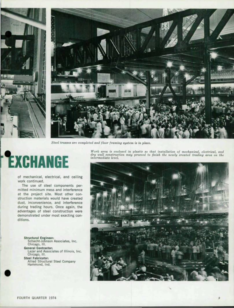
View 01 trading .ellion under lonr temporary column. and bottom cllord. 01 the .teel trulle.
Top chord 01 one 01 the steel trusse. being brought into 'Po.ition at night
by Robert W. Shuldes
When the Chicago Board of Trade, the largest commodities trading market in the world, required additional space, they decided to add an intermediate floor to their 75·ft high, 20,000 sq-ft trading hall, rather than move to larger quarters. The existing building, de· signed in 1929, is the world famous Board of Trade Building, which fea· tures the six·story trading hall.
Adding a new floor midway above the 120·ft x 175-ft trading floor was budgeted at a cost of $2.5-million.
Steel Trusses Span Trading Floor The new floor is a composite steel
deck supported by two 10-ft deep steel trusses that span 120 ft across the trading floor to provide column-free space both above and below the new deck. Set 57 ft apart, the trusses are framed into existing columns. Wide
Mr. Shuldes is AISC Relion.1 Ensineer, Chic.so, III.
8
STEEL TRUSSES SUPPO flange beams span 57 ft between the trusses and are framed into the bottom chords of the trusses.
Although this addition added considerable weight to the existing structural frame, the columns were not enlarged because the design formulas utilized 40 years ago were conservative enough to permit the additional column loads under today's more liberal specifications and codes.
Construction Time Restricted The project presented a challenge
not normally encountered in remodeling and alteration work: No construction work could take place during trading sessions. All building activity was restricted to the hours between 3 p.m. and 8 a.m. on weekdays and all day on weekends. Furthermore, no equipment or materials on the premises could interfere with the trading pits, quotation boards, clerks' stations, or communication equipment.
The engineers and general contractor used a scale model to rehearse the sequence of a II facets of the project. In addition, the City of Chicago cooperated by agreeing to close off Jackson Boulevard and La Salle Street at night to enable cranes to operate from positions set up in the street outside the Board of Trade Building and feed the structural components through two large windows that had been removed.
Temporary Columns Support Steelwork All steel was test assembled in the
fabrication yard, steel deck was precut and predrilled before delivery to the site. Four temporary columns were set up to support the steelwork. Beams were fed through the open windows by a crane. A small derrick, mounted inside, positioned the members.
Upon completion of the floor framing system, temporary columns were removed. The work area was closed off in plastic while progress on installation
MODERN STEEL CONSTRUCTION
•
•
Steel trusses are completed and floor framing system 'is in place.
CHANGE of mechanical, electrical, and ceili ng work conti nued.
The use of steel components permitted minimum mess and interference at the project site. Most other construction materials would have created dust. inconvenience, and interference during trading hours. Once again, the advantages of steel construct ion were demonstrated under most exacting conditions.
Structural Engineer: Schacht·Johnson Associa tes, Inc, Chicago, III.
General Contractor: Lazar and Associates of Illinois, Inc, Chicago, III.
Steel Fabricator: Allied Structural Steel Company Hammond, Ind .
FOURTH QUARTER 1974
Work area 1S encloBed in plaBtic BO that installation of m~chanical. electrical, and dry wall conltnlction may proceed to jill ish the newly created tradillU area on the intermediate level.

.----- • by Francis R. Hoffman
A TWO-STORY HIGH RISE
10 MODERN STEEL CONSTRUCTION

T
•
•
•
Architect: Francis R. Hoffman & Associates Los Angeles, Calif.
Structural Enlineer: Socoloske, Zeiner and Associates Van Nuys, Calif.
General Contractor: Appel Construction Company Los Angeles, Calif.
Steel Fabricator: Riverside Steel Construction Santa Fe Springs, Calif.
A last minute decision by a leading West Coast bank set into motion a chain of events that resulted in the conversion of a nearly completed twostory concrete structure into an imposing II-story high-rise steel office building. Although the complexity of the changeover was enormous, it was accomplished with an ease more typical today of changing the prime interest rate than of completely redesigning a $6.6-million bank building.
The new ll-story United California Bank B/lilding in Glendale, California was originally conceived as a two-story structure containing approximately 35,-000 sq ft of space. Construction on the shell of the structure had almost been completed, with even the steel roof being installed.
Revised growth projections for the area made the bank feel that it would be shortsighted to complete the planned two-story structure only to outgrow it within a few years. Instead, it decided to provide space both for the present and future needs it anticipated in the area. The 35,000 sq-ft floor space became 121,000 sq ft.
The addition of nine stories of steel required changes that affected prac· tically every phase of design and construction. With the exception of the roof on the two-story structure, which had to be removed, all of the original building shell was retained.
One reason we were able to quickly accommodate the bank's changes is that we had considered the expansion possibilities earlier in the original design, but the developer felt that the added expense was not in proportion to the project cost at that stage. Naturally, we didn't expect that expansion to occur so rapidly that it would take place before construction was even completed on the new building, but
Mr. Hoffman is the prlnci~1 of the architectural firm FranciS R. HoHman & Associ,tes, los Ana.les, C.lif
FOURTH QUARTER 1974
when it did we had all of the conceptual groundwork laid to proceed without any lost time.
A number of difficult engineering problems had to be solved. Moment connections between the existing concrete structure and the new steel tower were critical. Existing interior column capacities were increased with rein· forcing steel and gunite. Foundations were enlarged and deepened. Air conditioning systems were revised and utility services increased. Fire protection and emergency systems had to be installed to cover the existing structure as well as the addition.
While the general contractor was pouring additional footings and beefing up the foundation to carry the additional weight, we were striving to complete working drawings for other modifications. In fact, we were still designing the building while the contractor installed the structural steel for the additional floors. It was quite literally a hand·to·mouth operation.
Fortunately, the 2-ft x 3-ft exterior concrete columns were sturdy enough to carry the additional loads. Although it was not planned that way, we had sized them large as an architectural amenity. However, the 14-in. square interior columns were too weak. These existing columns were shored, sandblasted at the corners, and additional reinforcing bars added before high strength concrete was gunited onto the columns. This process resulted in a 21-in. square column. But the interior columns would have had to have been very much larger if we had not decided to build the additional nine stories out of steel, rather than continue the concrete upward. Opting for steel because of its lighter weight, the engineers had their own migraines. They had to make sure the two-story concrete columns and the nine·story steel ones would act together to resist lateral and vertical
stresses; after all, the building is in a high earthquake risk area.
To join the two diverse elements, the steel roof of the Original building had to be removed. Then the reinforcing bars of the exterior concrete columns were exposed six inches and a detailed base plate added to wed the steel and concrete.
The most difficult part in redesign was not the interior rearranging, but the exterior. We did not want the structure to look like two different buildings or one added as an afterthought, so we cement plastered the exterior columns and textured them from grade to roof, so that now the hybrid building looks as if it were intended to be II stories from the very beginning .
As an architect, I am proud not just of the fact that the changeover from low to high-rise was accomplished economically but that the finished product is an aesthetiC asset to the community. Of course, on my next project I would like to achieve the same results without any eleventh-hour change of plan.
Column Base Plate
11

Conversion to Steel Frame
Saved Time and Money . ...
MODERN STEEL CONSTRUCTION
•
•
•
•
I
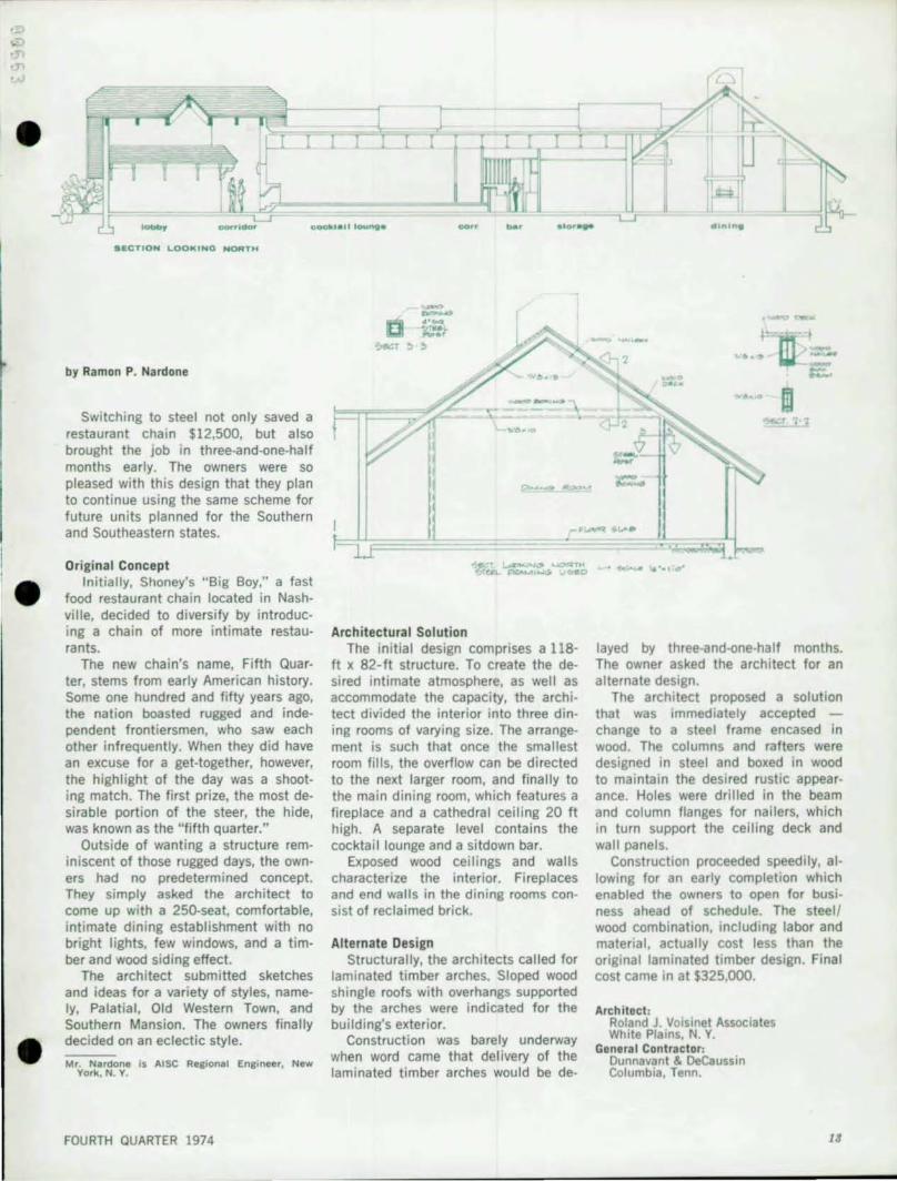
'- acwridOf" ooettl_11 lounge ... .'Of'",
•• eTION LOOKtNO NORTH
by Ramon P. Nardone
Switching to steel not only saved a restaurant chain $12,500, but also brought the job in three-and-one-half months early. The owners were so pleased with this design that they plan to continue using the same scheme for future units planned for the Southern and Southeastern states.
Original Concept Initially, Shoney's "Big Boy," a fast
food restaurant chain located in Nashville, decided to diversity by introducing a chain of more intimate restaurants.
The new chain's name, Fifth Quarter, stems from early American history. Some one hundred and fifty years ago, the nation boasted rugged and independent frontiersmen, who saw each other infrequently. When they did have an excuse for a get-together, however, the highlight of the day was a shooting match. The first prize, the most de· sirable portion of the steer, the hide, was known as the "fifth quarter."
Outside of wanting a structure reminiscent of those rugged days, the owners had no predetermined concept. They simply asked the architect to come up with a 250-seat, comfortable, intimate dining establishment with no bright lights, few windows, and a timber and wood siding effect.
The architect submitted sketches and ideas for a variety of styles, namely, Palatial, Old Western Town, and Southern Mansion. The owners finally decided on an eclectic style.
Mr. Nardone is AISC Regional Engineer, New York, N. Y.
FOURTH QUARTER 1974
-u -
Architectural Solution The initial design comprises a 118-
ft x 82·ft structure. To create the desired intimate atmosphere, as well as accommodate the capacity, the architect divided the interior into three dining rooms of varying size. The arrangement is such that once the smallest room fills, the overflow can be directed to the next larger room, and finally to the main dining room, which features a fireplace and a cathedral ceiling 20 ft high. A separate level contains the cocktail lounge and a sitdown ba r.
Exposed wood ceilings and walls characterize the interior. Fireplaces and end walls in the dining rooms consist of reclaimed brick.
Alternate Design Structurally, the architects called for
laminated timber arches. Sloped wood shingle roofs with overhangs supported by the arches were indicated for the building's exterior.
Construction was barely underway when word came that delivery of the laminated timber arches would be de-
• ... •••
"" ..... III m
----...-'
layed by three-and-one-half months. The owner asked the architect for an alternate design.
The architect proposed a solution that was immediately accepted -change to a steel frame encased in wood. The columns and rafters were designed in steel and boxed in wood to maintain the desired rustic appearance. Holes were drilled in the beam and column flanges for nailers, which in turn support the ceiling deck and wall panels.
Construction proceeded speedily, allowing for an early completion which enabled the ownerS to open for business ahead of schedule. The steel I wood combination, including labor and material, actually cost less than the original laminated timber design. Final cost came in at $325,000.
Architect: Roland J. Voisinet Associates White Plains, N. Y.
General Contractor: Dunnavant & DeCaussi" Columbia, Tenn .

1974 ARCHITECTURAL
AWARDS OF EXCELLENCE
14
STUDIO Highland Parkl Illinois Architect: DaYld Held
~ THE. HILLIER GROUP BUILDING West Windsor, New Jersey Architect: J . Robert Hillier
~
.. FEDEAAL RESERVE SANK OF MINNEAPOLIS Minneapolis, Minnesota Architect: GUnnar 8 irkerts and Associates
FRANK B. HALL .. CO., INC. OFFICE BUILDING Briucliff Manor, New York Architects : M."Jrice A Capobianco
Fleaal. and Kaeyer
NATIONAL AIRLINES, INC., HANGAR NO.2 Miami, Florida DesIgners: (A Joint Venture)
Greenleaf/Telesca Kellermann & Dragnett, Inc.
MODERN STEEL CONSTRUCTION
•
•

•
HEADQUARTERS BUILDING FOR THE PROGRESSIVE FARMER COMPANY Blrmlnlh_m, AI_~m_ Archit.ct; JO\Ia/Oaniels/Busby
... PAGE SOUTHERLAND PAGE HEAOQUARTERS BUILDING Austin, T ... s ArchitKt: P.,. Southerl.nd P., •
FOURTH QUARTER 1974
HOMESTEAD fEDERAL SAVINGS AND LOAN ASSOCIATION 0.yl0n, OhiO Architect: Rich.,d Levin AsSOCI.t.s Inc.
~ UNITED STATES PAVILlOH, EXPO '14 Spok.ne, W.sh~n,ton Architect: Nar1lmor. a.in ar1ldy & Johnson
SEATTLE CEHTER COVERED WALKWAY S 5 •• ttle, Washin£1on Architect: Th. Rlch.rdson Associ.t"
16

AMERICAN INSTITUTE OF STEEL CONSTRUCTION 1221 Avenue of the Americas New York, N. Y. 10020
----Address Correction Requested
~ PARAMUS PARK SHOPPING CENTER Paramus, New Jersey Architect: RTKL Associates Inc
DOWNTOWN MALL Sioux Falls, South Dakota Architects: The Spitznagel Partners Inc.
Herb Baldwin
~ CONTROL CENTER FOR POWER PLANTS Lawton, Oklahoma Pittsburah, Pennsylvani. Architect: Robert l. Zleplman
BULK RAT[ US POSTAGE
PA ID
NEWYORK.NY Permit No 6662 •