s hu welder beha vi m l f p w p torc pure
TRANSCRIPT

Study on Human Welder Behavior by Measuring LocalFlow Pattern of Weld Pool and Torch Posture
Ding Fan(✉), Xiaochun Dun, Gang Zhang, and Yu Shi
State Key Laboratory of Advanced Processing and Recycling Nonferrous Metals,Lanzhou University of Technology, Lanzhou 730050, China
Abstract. To study human welder behavior by sensing the welding torch postureand weld pool flow pattern, so as to provide a way to realize intelligent robotwelding, a synchronous experiment system is setup with laser vision and adynamic tilt sensor to precisely obtain the three-dimensional information of weldpool and torch posture. In the downward welding experiment, the data of reflectedlaser striped image of weld metal fluid flow and the change of torch posture areobtained. The algorithm for extracting weld metal fluid flow characteristic param‐eters is also written to obtain the weld pool flow pattern. Through the experimentanalysis, it is found that the change of weld pool flow characteristic parametersand the change of torch posture have obvious coherence. The change of torchposture reflects the reaction and control ability of the human welder. The changeof the weld pool flow characteristic parameters reflects that the welder maintainsspecific weld metal fluid flow pattern and obtains good weld forming ability.
Keywords: GTAW · Human welder behavior · Laser vision · Local flow pattern ·Weld pool · Torch posture
1 Introduction
It is found that through observing the surface of weld pool, skilled welders can adjust thewelding torch posture correctly to control certain penetration status, and to control the welddefects so as to obtain homogeneous weld as much as possible [1]. However, it needs along-term to train human welders for getting skills and experience. Welders’ experience isthe interaction behavior between people and weld pool. In order to realize intelligent robotwelding [2], many scholars of home and abroad have studied the interaction behaviorbetween human welder and weld pool. Liu Yukang, Zhang Yuming [3–6] made someresearches on human welder behavior relating to welding current and welding speed, theyproposed an adaptive neuro-fuzzy inference system (ANFIS) to correlate the humanwelder’s response to the 3D weld pool surface as characterized by its width, length andconvexity. Japan’s Aoyama Gakuin University [7] made a research on welder behaviorswith four cameras to record the positions of tungsten electrode tips in the TIG welding withfiller wire process. British M.S. Erden [8] identified the difference between skilled welderand unskilled welder by analyzing the data of welding torch tip’s position which wasobtained from a three-dimensional motion capture system, and the result showed that
© Springer Nature Singapore Pte Ltd. 2018S. Chen et al. (eds.), Transactions on Intelligent Welding Manufacturing,Transactions on Intelligent Welding Manufacturing, DOI 10.1007/978-981-10-5355-9_2

skilled welders can control the welding torch tip and limit the torch speed to vary in asmall range. Liu Yukang, Zhang Yuming [9] also established a virtual welding system,which successfully finished the welding on a pipeline, and they obtained a good weldformation. They established a predictive control algorithm, made the automated GTAWpipeline welding experiment with different welding current and speed. The result showedthat the algorithm has a good robustness. However, these studies are all focused on thecontrol or regulation of the energy index of the weld pool. On the one hand, the regulationof energy is easy to make the temperature gradient change relatively, which makes theweld pool unstable. On the other hand, the regulation of energy is easy to make the prop‐erty of welded joint change greatly, which influences the follow-up service of welds.Therefore, this paper proposes a new experimental scheme that intends to control weldingtorch posture to change the weld metal flow pattern of weld pool and adjust local heat inputof the thermodynamic coupling process. At present, direct measurement of the weld metalflow pattern is very difficult. Although some researchers have investigated the measure‐ments of molten pool fluid flow in metallic melts [10, 11], those processes are not associ‐ated with actual welding conditions.
This paper focuses on qualitatively studying the correlation of the welding torchposture and the local flow pattern of the weld pool, which in turn reflects the humanwelder’s responses on the varying weld pool surface, and verifies the proposed schemeto investigate the interactive behavior of welder. To this end, a synchronous acquisitiontest system, including a five-line-mode-structure laser vision to measure the flow patternof weld pool and a dynamic angle sensor sensing the data of welding torch posture wereestablished, and the verified experiment was performed.
2 Experimental Principle and System
2.1 Experimental Principle
During TIG welding process, the surface of liquid weld pool carries important weldingphysical information. However, during the welding process, the change of the weldmetal fluid flow cannot be measured directly. Therefore, this paper presents the meas‐uring method of using the striped laser vision to measure the local flow pattern of weldpool. The laser stripes produced by low-power structured laser are projected, coveringon the surface of weld pool. The changes of the laser stripes reflected on the surface ofthe weld pool are observed and recorded by the CCD camera and stored in the computer.Because the laser stripe pattern, which is projected onto the surface of weld pool witha certain geometric parameter and imaged after specular reflection, has a strict opticalcorrespondence with the change of the flow pattern of weld pool on the surface, so thespatial geometrical mapping optical model established between the weld pool and theprojected laser stripes can realize the dynamic measurement of the weld metal fluid flow.The principle is shown in Fig. 1.
28 D. Fan et al.

z
x
y
io
workpiece weld pool
laser generator
imaging plane
Pt
Pt+ tΔ
Fig. 1. Experimental principle
2.2 Experimental System
According to the principle of measuring the flow pattern of weld pool by laser vision inFig. 1, the experimental system of synchronous acquisition in Fig. 2 is established. Theexperimental system of synchronous acquisition uses the MPU6050 sensor to sense thewelding torch posture. In the system, a structured laser with wavelengths of 658 nm,37.5 mW is placed in plane OYZ, and it was about 90 mm from the weld pool, and about30° from the work-piece. In the plane OXZ, an imaging screen is vertically or obliquelyplaced about 53 mm from the weld pool to intercept the striped lacer reflected by theweld pool surface. The system uses the high-speed CCD camera to record the reflectedlaser image. In order to further reduce the impact of the arc exerts on the image quality,CCD camera lens is equipped with a 660 ± 10 nm band-pass filter. It uses AC-DCinverter welding machine TIG315AC/DC as a welding power source. During thewelding process, the torch is supported by the universal joint and adjusts the directionand speed of welding trolley by the stepper motor combined with an inverter.
z
x
y
CCD camera
Laser generator
Tilt sensor
Weld pool
Projecteed laser lines
Imaging plane
Reflected laser lines
Image process and coordinate transformation
Weld pool parameters
Weld torch attitude
O
Fig. 2. Experimental system
Study on Human Welder Behavior 29

3 Experimental Procedure and Discussion
3.1 Image Processing Algorithm
In order to extract the laser stripes’ curvature radius from the collected laser stripe image,the image should be preprocessed at first. In order to remove the noise signal in thereflected laser stripe image, image filter method was adopted. Through the binarizationof image processing, the laser stripe is separated from the image and to study. The edgeof the laser stripe contains a wealth of intrinsic information, which is a basis to make adistinction between a laser stripes and another one. In order to facilitate the curve fittingof the laser stripes, it is necessary to perform the image edge detection on the edge ofthe laser stripe image, and then extract the edge value of the laser stripes, using the leastsquares fitting method to fit the midpoint between the upper and lower edges of the laserstripes. The fitting steps are as follows.
Fitting Laser Stripe FunctionAssuming the general expression of the image fitting function is:
(1)
where are constants.
Midpoint value should be fitted at first, and each midpoint value should be go onthrough, and then can be constructed, and finally the fitting function of themidpoint value in the laser stripe was obtained. Figure 3 shows the laser stripes’ midpointdetection, and the detected mid-points were fitted by the above function. The fitted curvecan be seen in Fig. 3 red line.
Fig. 3. Midpoint detection of laser stripe (Color figure online)
Solving the Laser Stripes’ Curvature Radius. After the function expression that canexpresses the laser stripe image is obtained, each should be goon through and tofind the first derivative . And then each should be goon
30 D. Fan et al.

through to find the second derivative , finally the first derivative func‐tion expression y′ of the function, and the second derivative function expression y″ canbe obtained.
Then according to the expression of curvature K:
(2)
Therefore, the curvature radius:
(3)
Thus the solution of the laser stripes’ curvature radius function expression isobtained, which is shown in Fig. 4.
Fig. 4. The curvature radius of the laser stripe
Representation of Local Flow Pattern of the Weld Pool. As shown in Fig. 1, the ithlaser stripe reflected by the surface of the weld pool is taken as an example. After aninterval time ∆t, point P(t) moved to point P(t + ∆t). Taking a small part of the liquidmetal on the surface of weld pool as an example, a micro displacement Δs occurred inthe pool. Taking the laser stripe on the imaging screen as the object of study, the reflectedlaser stripes’ curvature radius is changed from R(t) to R (t + ∆t), so the flow rate of theweld pool is:
(4)
Because so simply:
(5)
where c is a constant.
Study on Human Welder Behavior 31

So:
(6)
After the laser stripes curvature radius of function expression is obtained, the curva‐ture radius of each laser stripe. Since the length of the video time is T, the total numberof the pictures which obtained after framing is N, the flow rate is expressed as a functionbetween the change of curvature radius and time:
(7)
3.2 Experimental Results and Discussion
In order to extract characteristic parameters which reflect the change of flow pattern ofweld pool from the changing laser stripes, a program to extract the laser stripes’ curvatureradius is written in Lab VIEW by using the program flow chart shown in Fig. 5.
Fig. 5. The program flow chart of laser stripe image processing
32 D. Fan et al.

The established experimental platform was used to make a bead-on-plate weldingexperiment with 304 stainless steel, and the experimental parameters are shown inTable 1. When the laser stripes completely covered the surface of the weld pool, thelaser stripe images captured on the imaging screen were shown in Fig. 6. In order tostudy the welders’ behavior of adjusting flow pattern of weld pool by adjusting the weldtorch posture, the program which was written by the program flow chart shown inFig. 5 was used to process the laser stripe image.
Table 1. Experimental parameters
Name Material PlatethicknessH/(mm)
CurrentI/(A)
Arclengthl/(mm)
Weldingspeedv/(mm/s)
Gas flowQ/(L/min)
Parameters 304Stainlesssteel
3 60 3 1.5 8
Figure 6 shows laser stripe images which reflected by the weld pool surface duringthe welding process, and the image was formed under the DC current which was obtainedevery 3 s in the video shot by the high-speed camera with the sampling frequency of200 Hz. In Fig. 6, during the whole welding process, the shape of the laser stripe imageis changing constantly. There are 3 points selected in the second laser stripe image: thepoint near the center of the weld pool, the point near the edge of the weld pool and thepoint between the center and the edge of the weld pool. And the Fig. 7 shows the dynamicchanging curve of torch posture. Figure 7 shows the weld pool characteristic parametersof local flow pattern, which is obtained from Eq. (7). From the change trend of the wholecurve, we can receive the information that closer to the center of the weld pool, thegreater of curvature radius change rate will be, indicating that when the position is closer
Fig. 6. The typical reflection of the laser stripe (the time interval of images: 3 s)
Study on Human Welder Behavior 33
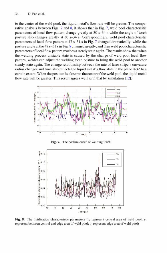
to the center of the weld pool, the liquid metal’s flow rate will be greater. The compa‐rative analysis between Figs. 7 and 8, it shows that in Fig. 7, weld pool characteristicparameters of local flow pattern change greatly at 30 s–34 s while the angle of torchposture also changes greatly at 30 s–34 s. Correspondingly, weld pool characteristicparameters of local flow pattern at 47 s–51 s in Fig. 7 changed dramatically, while theposture angle at the 47 s–51 s in Fig. 8 changed greatly, and then weld pool characteristicparameters of local flow pattern reaches a steady state again. The results show that whenthe welding process unstable state is caused by the change of weld pool local flowpattern, welder can adjust the welding torch posture to bring the weld pool to anothersteady state again. The change relationship between the rate of laser stripe’s curvatureradius changes and time also reflects the liquid metal’s flow state in the plane XOZ to acertain extent. When the position is closer to the center of the weld pool, the liquid metalflow rate will be greater. This result agrees well with that by simulation [12].
Fig. 7. The posture curve of welding torch
Fig. 8. The fluidization characteristic parameters (v0 represent central area of weld pool; v1represent between central and edge area of weld pool; v2 represent edge area of weld pool)
34 D. Fan et al.

4 Conclusions
A new method is proposed in this paper to characterize the local flow pattern of weldpool by mean of measuring the dynamic change rate of the curvature radius of weld poolsurface during welding process. The change of weld pool characteristic parameters oflocal flow pattern and the change of welding torch posture have obvious coherence,therefore it can characterize the human welder behavior in welding operation. The weldpool characteristic parameters of local flow pattern show that liquid metal flow rate atthe center of weld pool is greater than that at the weld pool edge. This result agrees wellwith that by similation.
Acknowledgement. Thanks for the help of Prof. Zhang Yuming of University of Kentucky inthis article. Thanks for the National Natural Science Foundation of China (No. 61365011-2014).
References
1. Liu YK, Zhang YM (2014) Control of human arm movement in machine-human cooperativewelding process. Control Eng Pract 32:161–171
2. Zhao WG, Li SK, Zhang BB (2016) Present situation and prospect of intelligent technologyfor welding robot. Dev Appl Mater 31(3):108–114
3. Liu YK, Zhang YM (2015) Iterative local ANFIS based human welder intelligence modelingand control in pipe GTAW process: a data-driven approach. IEEE Trans Mechatron 20(3):1079–1088
4. Liu YK, Zhang WJ, Zhang YM (2015) Dynamic neuro-fuzzy based human intelligencemodeling and control in GTAW. IEEE Trans Autom Sci Eng 12(1):324–335
5. Liu YK, Zhang YM, Kvidahl L (2014) Skilled human welder intelligence modeling andcontrol: part I-modeling. Weld J 93(2):46s–52s
6. Liu YK, Zhang YM, Kvidahl L (2014) Skilled human welder intelligence modeling andcontrol: part II-analysis and control applications. Weld J 93(5):162s–170s
7. Hashimoto N, Nakamura A, Ohishi S (2014) Traing system for manual arc welding usingartificial reality measurement of manual welding motion for skill evaluation. Weld J 93:388–398
8. Erden MS, Tomiyama T (2009) Identifying welding skills for training and assistance withrobot. Sci Technol Weld Joining 14(6):523–532
9. Liu YK, Shao Z, Zhang YM (2014) Learning human welder movement in pipe GTAW: avirtualized welding approach. Weld J 93:388s–398s
10. Hanao M, Kawamoto M, Mizukami H et al (2000) Influence of molten steel flow velocitynear the meniscus in continuous casting mold on surface quality of slabs. Iron Steelmaker27(11):55–59
11. Ricou R, Vives C (1982) Local velocity and mass transfer measurements in molten metalsusing an incorporated magnet probe. Int J Heat Mass Transf 25(10):1579–1588
12. Hang JK, Guo CB, Fan D (1992) Numerical analysis of molten pool in TIG welding stepparameters. Trans China Weld Inst 28(10):47–52
Study on Human Welder Behavior 35