s lar powered bike rack system - ucf department …€¦ · s lar powered bike rack system v daniel...
TRANSCRIPT

S LAR POWERED BIKE RACK SYSTEM
v Daniel Adarme (E.E)
v The Pham (E.E)
v Christine Erwin (E.E)
v Nha Nguyen (E.E)

Table of Content
u Motivation
u Goal and objective
u Specification
u Structural Design
u Hardware Design : Power System, DC-AC, locking system, applications
u Software Design: Embedded System
u Project Budget and Finance
u Question

MOTIVATIONu Typical bike rack does not fully protect the bike from bad weather
u Not safe to walk to the bike rack at NIGHT TIME on campus
u BIKE LOCK KEY can be STOLEN or LOST
u BIKE can still be STOLEN even if it is locked to the rack
u Campus is large and time gap between classes is short
u There is a huge demand for charging station for Electric Bikes

Goals and Objectives
• Bikes can be fully protected from bad weather by built-in roof
• Embedded locking system is added to the rack for easy access
• Magnetic Card Reader device is added to locking system to improve security/Identification purpose
• Only student with valid ID has the access to the bike station (preventing outside thefts)
• LED lights and Security camera being added the system provide more safety at night time
• Motion Detection Sensor is added to the system for energy efficient purpose
• Bike Sharing System is designed to help students with easy commuting between place to place
• The 110V AC outlet is provided to charge electric bikes
• Power will be provided 100% by the OFF-GRID Solar Power System

Specifications
Component Parameter Design Specification
Power Storage System(Deep Cycle Battery)
Discharging Duration without power provided by solar panel STILL MAINTAIN ABOVE 50% CAPACITY
12 HOURS
Solar Charge Controller VOLTAGE RATING and CURRENT RATING ~12V DC and 5A DC
Solar Charge Controller Power Efficiency greater than 75%
Power Distribution System(DC-DC converter)
Power Consumption Less than 5W
Power Distribution System(DC-DC converter)
Total System Efficiency Above 95%
DC-AC inverter Stable AC Power Supply 110V 60Hz
Microcontroller Low power, wireless comm. capable 3.3V max, WiFi
Motion Detection Sensor Viewing distance/range 270 degree, 2 meters

Over All Structural Design
Component Parameter Desired Value
Over AllStructural
Height 6.0 Feet ~ 7.0 Feet
Structure Support Force Capability
60 lbs
Structure Estimated Cost
$50~$100
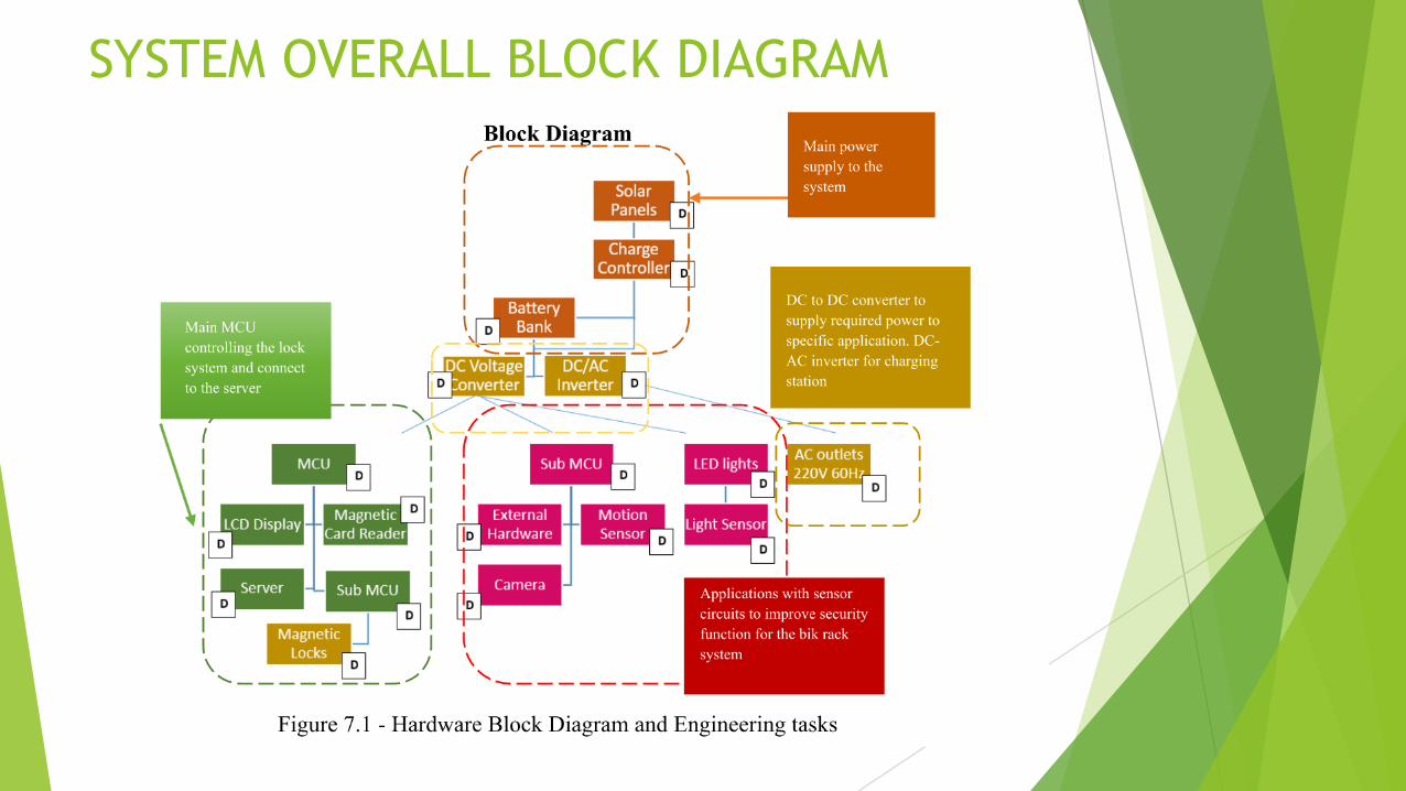
SYSTEM OVERALL BLOCK DIAGRAM

Changing Decision on POWER SYSTEMu Time and financial constraints affected on initial system design decision
NAME INITIAL DESIGN NEW DESIGN Reason to Change ADVANTAGE/DISADVANTAGE
SOLAR PANELS 200WPolycrystalline18V rating voltage10A rating current
100W Monocrystalline18V rating voltage6A rating current
Financial Constraint • Less weight• Smaller
Dimension• Cost Reduced
by $80• Taking longer
to charge
BATTERIES Golf Cart BatteriesDeep Cycle430 Ah 12V5.16 kWh
AGM Deep Cycle105 Ah12V1.26 kW
Financial ConstraintLack of information
• Cost reduced by $200
• Smaller Size• Less power
capability
SOLAR CHARGE CONTROLLER
MPPT PMP765 TI CHARGE CONTROLLER REFERENCE DESIGN
SOLID STATE SWITCH CHARGE CONTROLLER
Time ConstraintBudget ConstraintRequired knowledge in coding
• No Codes Required
• Cost reduced by $50
• Less Efficiency

Solar Photovoltaic Devices for the Systemu Photovoltaic Device Materials Choice: Monocrystalline Technologies
u HIGHER POWER EFFICIENCY and SMALLER IN SIZE
Specifications
Quantity 2 Panels connects in Parallel
OptimumOperating Voltage (Vmp)
18.5V
OptimumOperating Current(Imp)
5.40 A

Power Storage Systemu AGM (Absorbent Glass Mat) Deep Cycle Battery
u Most Safety and Least Maintenance required compared to other types
Specifications
Quantity 3X Battery
Cycle Use Voltage 14.5V~14.9V
Total Capacity 105 AhOr 1.43 kWh
Charging Time required to reach full stage from 50% capacity
10 Hours

POWER SYSTEM BLOCK DIAGRAM
SOLARSSSCHARGE CONTROLLER
POWER STORAGE SYSTEM(DEEP CYCLE BATTERY)
POWER DISTRIBUTION SYSTEM
SYSTEM LOADS
12V 35A Deep Cycle AGM Battery CONNECT IN SERIES
Protection Fuse

SOLID STATE SWITCH SOLAR CHARGE CONTROLLER
u Low cost construction
u Easy to troubleshoot
u Requires less power consumption
u Requires less maintenance
u Light weight and small dimension
u No programming code required
0
1
2
3
4
5
6
Cost Efficiency Maintenance Complication
Comparison Chart Between different types of Charge Controller
ON/OFF PWM MPPT
Rating Scale• 5: Desirable• 2-4: Average• 1: Not Desirable

Solid State Switch Charge Controller Block Diagram
Solar Panel
Terminal
Adjustable pot feeding desired cut-off voltage to comparator circuit to drive the MOSFET Switch
Four comparator circuits connected as S-R FLIP-FLOP with wire OR output to taking in inputs and driving the MOSFET
Voltage Buck Regulator to provide QUAD-Comparator reference voltage value and power clock generator
Lock Oscillator period generate 30mS Pulse every 15s. Its function to set the flip flop so that charging may commence
Battery Full Charge Voltage is at 14.5V
18V ~ 20VP Channel MOSFET
TI-LM317LZTI-LM339N
50K TrimPot
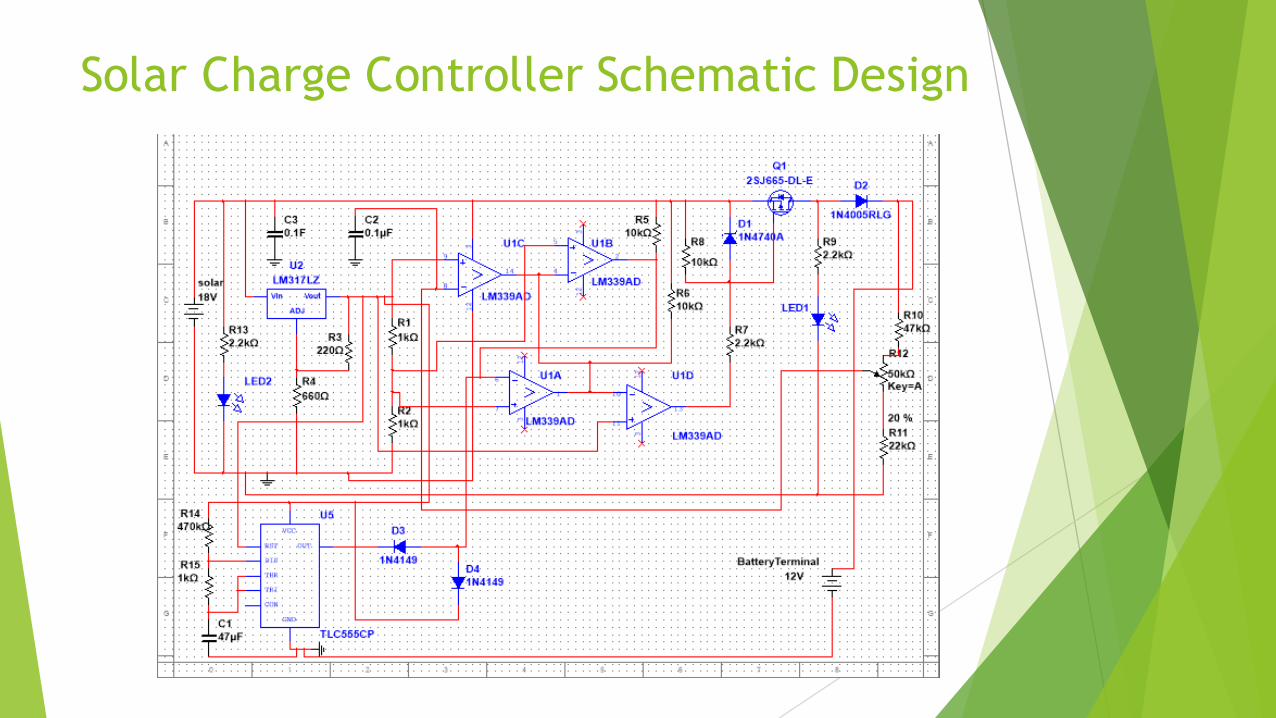
Solar Charge Controller Schematic Design

EagleCAD Solar Charge Controller Schematic Design

PCB Board Design

Power Distribution System
COMPARISON CHART
EFFICIENCY COST
OPTIMIZATION

DC-to-AC Power Converter
• Input 12VDC / Output 120VAC 60Hz
• N-channel MOSFET H-bridge Configuration
• MOSFET Driver
• Pulse Width Modulation (Sine wave Reference Signal, Triangular Carrier Signal, and Comparators)
• Low Pass Filter
• Surge Protection

DC-to-AC Power ConverterBlock Diagram

DC-to-AC Power ConverterSchematic Design

DC-to-AC Power ConverterSurge Protection
• Current from Inductors flow back to off MOSFETs
• Snubber Circuit with Zener Diode is used to damped the surge current
• Rsn, Csn, and Zener Diode are connected parallel to MOSFETs

DC-to-AC Power ConverterPCB Design
• Dimension : 159 mm x 213 mm (W x L)
• 2 Layers• Designed by Software CS
EAGLE ver 7.5.0

DC-to-AC Power ConverterPCB Design
Top View Bottom View

DC-to-AC Power ConverterDesign Implementation on Breadboard

• Pull-type Solenoid• Part A#420-066842-00 manufactured by Guardian Electric is used for low power
consumption and high achievable pull force
Locking Mechanism


Locking Mechanism
INITIAL STAGEAt this stage, system verifies user’s valid ID
SIGNAL IS SENT TO SUB MCUSTEEL BAR PULLED BACK BY SOLENOID WHILE WAITING FOR PROPER PLACEMENT
SIGNAL OFF, BACK TO INITIAL STAGE
ENCLOSED BOX CONTAINTED SUB MCU CONTROLING SOLENOID
EXTENDED STEELBAR
SOLENOID
Front Tire inserted and properly place in the
center
FRONT TIRE IS SECURELY LOCKED BY
THE STEEL BAR
FRONT VIEW FRONT VIEW FRONT VIEW

TOP VIEW OF LOCKING SYSTEM
RELAY RELAY RELAY

Lighting System Features
u Only on between the hours of 6:00 PM and 6:00 AM and off otherwise using RTC
u Activated via motion sensor
u Controlled using TI CC3200
u Designed for the safety of the user
u Circuit switched using 5V relay
u Flyback diode used to protect against relay spikes

Camera System Features
u Sends video footage to a server
u Footage is intended to be used to retrieve information on stolen bicycles
u Surveillance deters theft
u Cameras are activated when someone is nearby via the PIR motion sensor
u Controlled using CC3200

Lighting/Camera System Hardware General Diagram

Lighting System Code Block Diagram

Camera System Code Block Diagram

Embedded System
u Tiva C Series
u SimpleLink CC3200
u Code Composer Studio
u RFID Reader
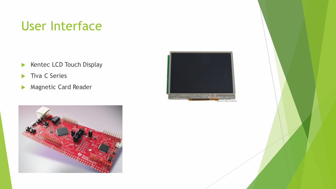
User Interface
u Kentec LCD Touch Display
u Tiva C Series
u Magnetic Card Reader

Software Block Diagrams

Software Block Diagrams

Software Block Diagrams

Software Diagram

Graphical User Interface

Graphical User Interface

Graphical User Interface

Graphical User Interface

WORK DISTRIBUTIONName Major Area of interest Project design
The Pham Electrical Engineering Electric Power System and Electronic Device
• Solar Power System• Structural Design• DC-DC Converter
Nha Nguyen Electrical Engineering Electronic Device and Integrated Circuit Design
• DC-AC Inverter• Locking Mechanism• Embedded System
Christine Erwin Electrical Engineering Electric Power System and Application
• SecurityCamera• Motion Detection• Light Sensor
Daniel Adarme Electrical Engineering Embedded system and communication system
• Main Embedded system• Electric Lock system• Structural Design

Financing and Fundraising
u The project was not funded by any company
u Late in March, fundraising for the project was created on “gofundme.com” site
u Goal for Fundraising was set at $1000 and duration of 2 WEEKS
u Result: LESS THAN 2 WEEKS, the goal $1000 was reached by the helps from family and friends

Proposed Budget TableName Quantity/Types Price/unit Status
Solar Panel 2x(50 watts offgrid solar panel) $200 confirmed
Charge Controller Charge Controller (Included PCB) $35 research
Battery 2x(215 Ah 6V Golf Cart Battery) $200 research
DC-DC inverters 5 Circuits $70 research
DC-AC inverters 1 $30 research
TI CC3200 SimpleLink 1; sample from TI $0 donated
TI CC3200 Launchpad 1 $0 donated
Magnetic card reader 1/prime eligible $17.78 purchased
RFID reader 1/prime eligible $12.80 purchased
TI Stellaris Launchpad 1 $13.38 In Transit
TI Stellaris LCD Module 1 $35 In Transit
FTDI Board (2) USB 2 I2C $9.95 In Transit
Phototransistor 1 $5 research
camera 1 $25 research
Microcontroller for the camera 1 $40 research
LED strip 1 $15 research
External hard drive 1 $65 research
Motion Sensor 1 $12 research
Bike Rack Structure
Others shipping cost, material cost $200 research
Total $985~$1000

Process
0 1 2 3 4 5 6
Embedded System
DC-AC and Locking Mechanism
Application System
Power System and Structural Design
Chart Title
Implementation Design and Prototyping Research

Question