s pages 721-762 creo lesson 17...
TRANSCRIPT

Creo Parametric Lesson 17
©2013CengageLearning.AllRightsReserved.Maynotbescanned,copiedorduplicated,orpostedtoapubliclyaccessiblewebsite,inwholeorinpart. 721
Lesson 17 Shell, Reorder, and Insert Mode
Figure 17.1 Oil Sink OBJECTIVES
Master the use of the Shell Tool Reorder features Insert a feature at a specific point in the design order Create a Hole Pattern using a Table Render the part using new lights Create a 3D PDF Detail the part
REFERENCES AND RESOURCES For Resources go to www.cad-resources.com > click on the Creo Parametric Book cover
Lesson 17 Lecture Book Projects PDF Project Lectures Creo Parametric Quick Reference Card
http://www.cad-resources.com/Creo_Parametric_Qick_reference_cards.pdf Creo Parametric Configuration Options
http://www.cad-resources.com/Creo_1.0_configoptions.pdf SHELL, REORDER, AND INSERT MODE The Shell Tool removes a surface or surfaces from the solid and then hollows out the inside of the solid, leaving a shell of a specified wall thickness, as in the Oil Sink (Fig. 17.1). When Creo Parametric makes the shell, all the features that were added to the solid before you chose the Shell Tool are hollowed out. Therefore, the order of feature creation is very important when you use the Shell Tool. You can alter the feature creation order by using the Reorder option. Another method of placing a feature at a specific place in the feature/design creation order is to use the Insert Mode option.
Creo Parametric Lesson 17
©2013CengageLearning.AllRightsReserved.Maynotbescanned,copiedorduplicated,orpostedtoapubliclyaccessiblewebsite,inwholeorinpart. 722
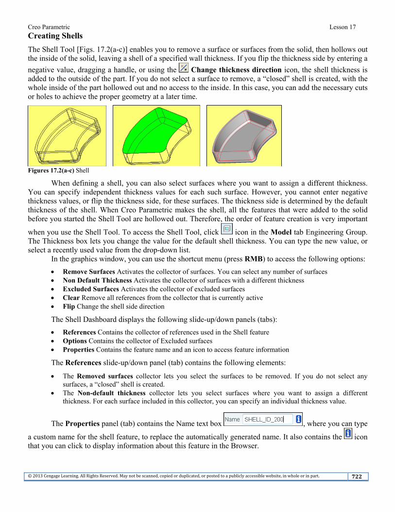
Creating Shells The Shell Tool [Figs. 17.2(a-c)] enables you to remove a surface or surfaces from the solid, then hollows out the inside of the solid, leaving a shell of a specified wall thickness. If you flip the thickness side by entering a
negative value, dragging a handle, or using the Change thickness direction icon, the shell thickness is added to the outside of the part. If you do not select a surface to remove, a “closed” shell is created, with the whole inside of the part hollowed out and no access to the inside. In this case, you can add the necessary cuts or holes to achieve the proper geometry at a later time.
Figures 17.2(a-c) Shell
When defining a shell, you can also select surfaces where you want to assign a different thickness. You can specify independent thickness values for each such surface. However, you cannot enter negative thickness values, or flip the thickness side, for these surfaces. The thickness side is determined by the default thickness of the shell. When Creo Parametric makes the shell, all the features that were added to the solid before you started the Shell Tool are hollowed out. Therefore, the order of feature creation is very important
when you use the Shell Tool. To access the Shell Tool, click icon in the Model tab Engineering Group. The Thickness box lets you change the value for the default shell thickness. You can type the new value, or select a recently used value from the drop-down list.
In the graphics window, you can use the shortcut menu (press RMB) to access the following options: Remove Surfaces Activates the collector of surfaces. You can select any number of surfaces Non Default Thickness Activates the collector of surfaces with a different thickness Excluded Surfaces Activates the collector of excluded surfaces Clear Remove all references from the collector that is currently active Flip Change the shell side direction The Shell Dashboard displays the following slide-up/down panels (tabs): References Contains the collector of references used in the Shell feature Options Contains the collector of Excluded surfaces Properties Contains the feature name and an icon to access feature information The References slide-up/down panel (tab) contains the following elements: The Removed surfaces collector lets you select the surfaces to be removed. If you do not select any
surfaces, a “closed” shell is created. The Non-default thickness collector lets you select surfaces where you want to assign a different
thickness. For each surface included in this collector, you can specify an individual thickness value.
The Properties panel (tab) contains the Name text box , where you can type
a custom name for the shell feature, to replace the automatically generated name. It also contains the icon that you can click to display information about this feature in the Browser.
Creo Parametric Lesson 17
©2013CengageLearning.AllRightsReserved.Maynotbescanned,copiedorduplicated,orpostedtoapubliclyaccessiblewebsite,inwholeorinpart. 723
Reordering Features
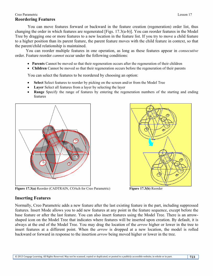
You can move features forward or backward in the feature creation (regeneration) order list, thus changing the order in which features are regenerated [Figs. 17.3(a-b)]. You can reorder features in the Model Tree by dragging one or more features to a new location in the feature list. If you try to move a child feature to a higher position than its parent feature, the parent feature moves with the child feature in context, so that the parent/child relationship is maintained.
You can reorder multiple features in one operation, as long as these features appear in consecutive order. Feature reorder cannot occur under the following conditions:
Parents Cannot be moved so that their regeneration occurs after the regeneration of their children Children Cannot be moved so that their regeneration occurs before the regeneration of their parents You can select the features to be reordered by choosing an option: Select Select features to reorder by picking on the screen and/or from the Model Tree Layer Select all features from a layer by selecting the layer Range Specify the range of features by entering the regeneration numbers of the starting and ending
features
Figure 17.3(a) Reorder (CADTRAIN, COAch for Creo Parametric) Figure 17.3(b) Reorder Inserting Features Normally, Creo Parametric adds a new feature after the last existing feature in the part, including suppressed features. Insert Mode allows you to add new features at any point in the feature sequence, except before the base feature or after the last feature. You can also insert features using the Model Tree. There is an arrow-shaped icon on the Model Tree that indicates where features will be inserted upon creation. By default, it is always at the end of the Model Tree. You may drag the location of the arrow higher or lower in the tree to insert features at a different point. When the arrow is dropped at a new location, the model is rolled backward or forward in response to the insertion arrow being moved higher or lower in the tree.

Creo Parametric Lesson 17
©2013CengageLearning.AllRightsReserved.Maynotbescanned,copiedorduplicated,orpostedtoapubliclyaccessiblewebsite,inwholeorinpart. 724
Lesson 17 STEPS
Figure 17.4 Oil Sink Oil Sink The Oil Sink (Fig. 17.4) requires the use of the Shell Tool. The shelling of a part should be done after the desired protrusions and most rounds have been modeled. This lesson part will have you create a protrusion, a cut, and a set of rounds. Some of the required rounds will be left off the part model on purpose.
Creo Parametric’s Insert Mode option enables you to insert a set of features at an earlier stage in the design of the part. In other words, you can create a feature after or before a selected existing feature even if the whole model has been completed. You can also move the order in which a feature was created and therefore have subsequent features affect the reordered feature. A round created after a shell operation can be reordered to appear before the shell, to have the shell be affected by the round.
In this lesson, you will also insert a round or two before the existing shell feature using Insert Mode. The rounds will be shelled after the Resume option is picked, because the rounds now appear before the shell feature. The details shown in Figures 17.5(a) through (h) provide the design dimensions.

Creo Parametric Lesson 17
©2013CengageLearning.AllRightsReserved.Maynotbescanned,copiedorduplicated,orpostedtoapubliclyaccessiblewebsite,inwholeorinpart. 725
Figure 17.5(a) Oil Sink Detail Drawing
Figure 17.5(b) Oil Sink Front and Right Side Views

Creo Parametric Lesson 17
©2013CengageLearning.AllRightsReserved.Maynotbescanned,copiedorduplicated,orpostedtoapubliclyaccessiblewebsite,inwholeorinpart. 726
Figure 17.5(c) Oil Sink Section A-A
Figure 17.5(d) Oil Sink Back View

Creo Parametric Lesson 17
©2013CengageLearning.AllRightsReserved.Maynotbescanned,copiedorduplicated,orpostedtoapubliclyaccessiblewebsite,inwholeorinpart. 727
Figure 17.5(e) Oil Sink Cutaway View
Figure 17.5(f) Oil Sink Front View Dimensions
Creo Parametric Lesson 17
©2013CengageLearning.AllRightsReserved.Maynotbescanned,copiedorduplicated,orpostedtoapubliclyaccessiblewebsite,inwholeorinpart. 728
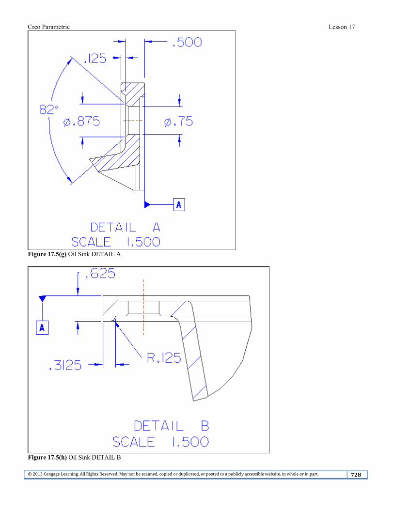
Figure 17.5(g) Oil Sink DETAIL A
Figure 17.5(h) Oil Sink DETAIL B

Creo Parametric Lesson 17
©2013CengageLearning.AllRightsReserved.Maynotbescanned,copiedorduplicated,orpostedtoapubliclyaccessiblewebsite,inwholeorinpart. 729
Click: File > Manage Session > Select Working Directory > select the working directory > OK > Ctrl+N
> oil_sink > > OK > File > Prepare > Model Properties (set the material and units): Material = steel.mtl Units = Inch lbm Second
Set Datum and Rename the default datum planes and coordinate system (Fig. 17.6): Datum TOP = B Datum FRONT = A Datum RIGHT = C Coordinate System = OIL_SINK
Figure 17.6 Set Datums and Renamed Coordinate System Make the first protrusion .50 (thickness) X 12.00 (height) X 18.00 (length), with R4.00 rounds (add the fillets to the sketch). Sketch on datum plane A, and center the first protrusion horizontally on datum B and vertically on datum C [Figs. 17.7(a-b)].

Creo Parametric Lesson 17
©2013CengageLearning.AllRightsReserved.Maynotbescanned,copiedorduplicated,orpostedtoapubliclyaccessiblewebsite,inwholeorinpart. 730
Figure 17.7(a) Dimensions for the First Protrusion
Figure 17.7(b) Standard Orientation Make the second protrusion offset from the edge of the first protrusion -3.00, with a height of 7.00 [Figs. 17.8(a-b)]. Sketch on the top surface of the first protrusion; then, create the cut [Figs. 17.9(a-b)].
Figure 17.8(a) Second Protrusion is Offset from the Edge of the First Protrusion

Creo Parametric Lesson 17
©2013CengageLearning.AllRightsReserved.Maynotbescanned,copiedorduplicated,orpostedtoapubliclyaccessiblewebsite,inwholeorinpart. 731
Figure 17.8(b) Second Protrusion
Figure 17.9(a) Cut
Figure 17.9(b) Standard Orientation of the Cut

Creo Parametric Lesson 17
©2013CengageLearning.AllRightsReserved.Maynotbescanned,copiedorduplicated,orpostedtoapubliclyaccessiblewebsite,inwholeorinpart. 732
Add the R1.50 rounds [Figs. 17.10(a-b)]. Draft all vertical surfaces of the second protrusion 10 degrees. Use the top surface as the Draft hinge [Figs. 17.11(a-b)].
Figure 17.10(a) Create the R1.50 Rounds Figure 17.10(b) Completed Rounds
Figure 17.11(a) Draft References

Creo Parametric Lesson 17
©2013CengageLearning.AllRightsReserved.Maynotbescanned,copiedorduplicated,orpostedtoapubliclyaccessiblewebsite,inwholeorinpart. 733
Figure 17.11(b) Drafted Sides
Click: > Thickness .375 > Enter > spin the model > References tab > Removed surfaces-- select
the bottom surface of the part [Fig. 17.12(a)] > > LMB > > > > Enter > File > Manage File > Delete Old Versions > Enter [Fig. 17.12(b)]
Figure 17.12(a) Shell Tool

Creo Parametric Lesson 17
©2013CengageLearning.AllRightsReserved.Maynotbescanned,copiedorduplicated,orpostedtoapubliclyaccessiblewebsite,inwholeorinpart. 734
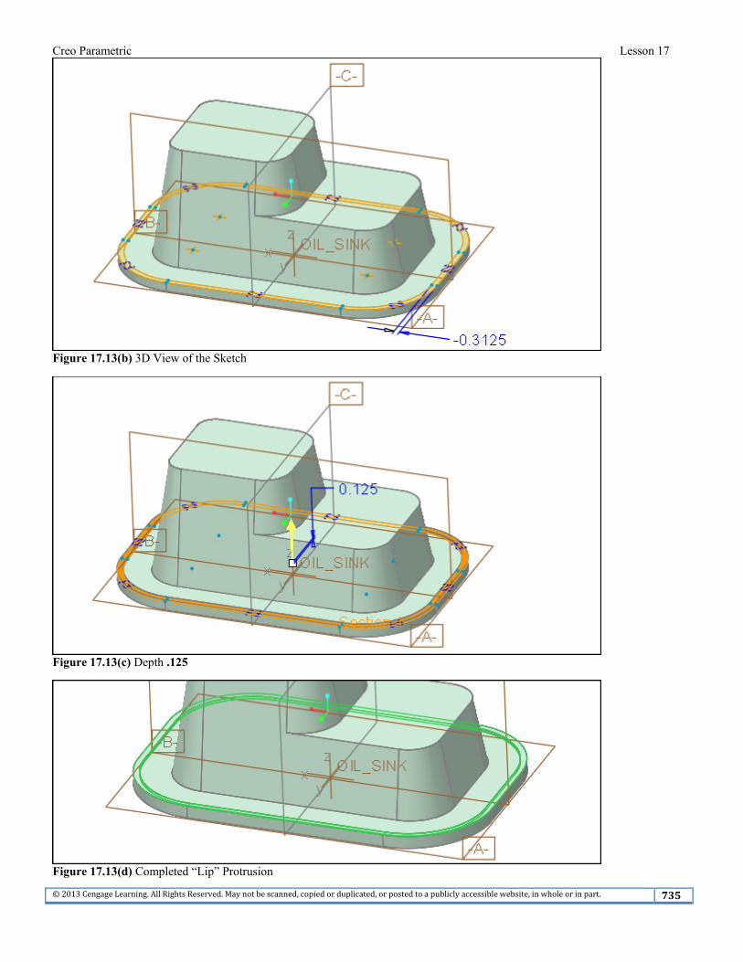
Figure 17.12(b) Shelled Part The next feature you need to create is a “lip” around the part using a protrusion. Press: Ctrl+D > sketch on the top surface of the first protrusion > sketch two closed loops [Fig. 17.13(a)]. Use the edge of the first protrusion for the first loop and then create an offset edge (-.3125) for the second loop [Fig. 17.13(b)]. > The depth of the lip protrusion is .125 [Figs. 17.13(c-d)].
Figure 17.13(a) Sketch Closed Loops
Creo Parametric Lesson 17
©2013CengageLearning.AllRightsReserved.Maynotbescanned,copiedorduplicated,orpostedtoapubliclyaccessiblewebsite,inwholeorinpart. 735
Figure 17.13(b) 3D View of the Sketch
Figure 17.13(c) Depth .125
Figure 17.13(d) Completed “Lip” Protrusion

Creo Parametric Lesson 17
©2013CengageLearning.AllRightsReserved.Maynotbescanned,copiedorduplicated,orpostedtoapubliclyaccessiblewebsite,inwholeorinpart. 736
Add the rounds: R.125 round on the inside of the “lip” [Fig. 17.14(a)] > spin the model > R.125 round to the inside edge [Fig. 17.14(b)] > spin the model > R.250 round between the first two extrusions [Fig. 17.14(c)] >
> Ctrl+S > Enter > LMB to deselect
Figure 17.14(a) Set 1 Round R.125
Figure 17.14(b) Set 2 Round R.125
Figure 17.14(c) Set 3 Round R.250

Creo Parametric Lesson 17
©2013CengageLearning.AllRightsReserved.Maynotbescanned,copiedorduplicated,orpostedtoapubliclyaccessiblewebsite,inwholeorinpart. 737
The countersunk holes will be added next, click: > spin the part > Drill to intersect with all surfaces > change the diameter to .750 > Placement tab > select the location on the surface for hole placement [Figs. 17.15(a-c)]
Figure 17.15(a) Hole Dimensions Figure 17.15(b) X-Section of Hole
Figure 17.15(c) Hole Placement View Orientation
Creo Parametric Lesson 17
©2013CengageLearning.AllRightsReserved.Maynotbescanned,copiedorduplicated,orpostedtoapubliclyaccessiblewebsite,inwholeorinpart. 738
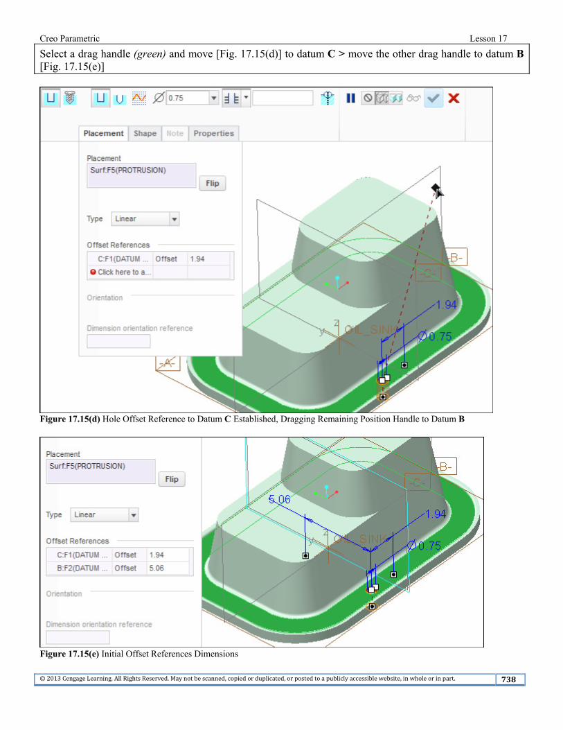
Select a drag handle (green) and move [Fig. 17.15(d)] to datum C > move the other drag handle to datum B [Fig. 17.15(e)]
Figure 17.15(d) Hole Offset Reference to Datum C Established, Dragging Remaining Position Handle to Datum B
Figure 17.15(e) Initial Offset References Dimensions
Creo Parametric Lesson 17
©2013CengageLearning.AllRightsReserved.Maynotbescanned,copiedorduplicated,orpostedtoapubliclyaccessiblewebsite,inwholeorinpart. 739
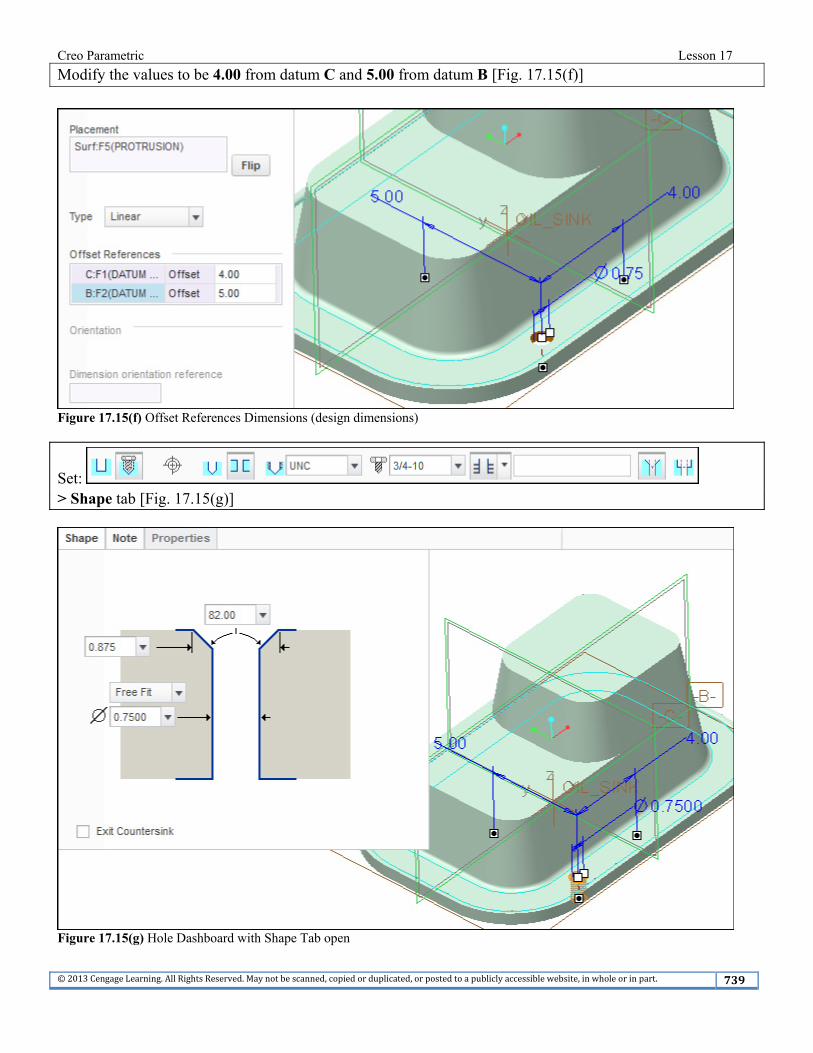
Modify the values to be 4.00 from datum C and 5.00 from datum B [Fig. 17.15(f)]
Figure 17.15(f) Offset References Dimensions (design dimensions)
Set: > Shape tab [Fig. 17.15(g)]
Figure 17.15(g) Hole Dashboard with Shape Tab open

Creo Parametric Lesson 17
©2013CengageLearning.AllRightsReserved.Maynotbescanned,copiedorduplicated,orpostedtoapubliclyaccessiblewebsite,inwholeorinpart. 740
Click: > Ctrl+S > Enter> check your settings in the Navigator > Settings > Tree Filters > toggle on all Display options > OK > click on the note in the Model Tree [Fig. 17.15(h)] > select the hole > press RMB >
Pattern > > [Fig. 17.16(a)]
Figure 17.15(h) Completed Countersunk Hole (your hole id may be different)
Figure 17.16(a) Pattern Members Defined by Table

Creo Parametric Lesson 17
©2013CengageLearning.AllRightsReserved.Maynotbescanned,copiedorduplicated,orpostedtoapubliclyaccessiblewebsite,inwholeorinpart. 741
Click: Table Dimensions tab > with the Ctrl key pressed, select the 4.00 dimension and then on the 5.00 dimension [Fig. 17.16(b)] > release the Ctrl key
Figure 17.16(b) Table Dimensions Tab with the 4.00 and the 5.00 Dimensions Added to the Table (your display may be different)
Click: [Fig. 17.16(c)] > add the information [Figs. 17.16(d-f)]
Figure 17.16(c) Pattern Table (your d symbols may be different)

Creo Parametric Lesson 17
©2013CengageLearning.AllRightsReserved.Maynotbescanned,copiedorduplicated,orpostedtoapubliclyaccessiblewebsite,inwholeorinpart. 742
Figure 17.16(d) Add numbers 1-7 Figure 17.16(e) Add Values in the Second Column (* means identical parent value)
Figure 17.16(f) Add Values in the Third Column From the Pro/TABLE window, click: File > Exit [Fig. 17.16(g)]
Figure 17.16(g) Completed Table

Creo Parametric Lesson 17
©2013CengageLearning.AllRightsReserved.Maynotbescanned,copiedorduplicated,orpostedtoapubliclyaccessiblewebsite,inwholeorinpart. 743
Click: [Fig. 17.16(h)] > Ctrl+S > Enter [Fig. 17.16(i)] > LMB to deselect
Figure 17.16(h) Previewed Pattern
Figure 17.16(i) Completed Pattern
Creo Parametric Lesson 17
©2013CengageLearning.AllRightsReserved.Maynotbescanned,copiedorduplicated,orpostedtoapubliclyaccessiblewebsite,inwholeorinpart. 744
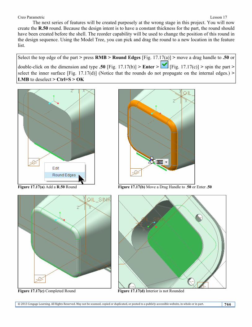
The next series of features will be created purposely at the wrong stage in this project. You will now create the R.50 round. Because the design intent is to have a constant thickness for the part, the round should have been created before the shell. The reorder capability will be used to change the position of this round in the design sequence. Using the Model Tree, you can pick and drag the round to a new location in the feature list. Select the top edge of the part > press RMB > Round Edges [Fig. 17.17(a)] > move a drag handle to .50 or
double-click on the dimension and type .50 [Fig. 17.17(b)] > Enter > [Fig. 17.17(c)] > spin the part > select the inner surface [Fig. 17.17(d)] (Notice that the rounds do not propagate on the internal edges.) > LMB to deselect > Ctrl+S > OK
Figure 17.17(a) Add a R.50 Round Figure 17.17(b) Move a Drag Handle to .50 or Enter .50
Figure 17.17(c) Completed Round Figure 17.17(d) Interior is not Rounded
Creo Parametric Lesson 17
©2013CengageLearning.AllRightsReserved.Maynotbescanned,copiedorduplicated,orpostedtoapubliclyaccessiblewebsite,inwholeorinpart. 745
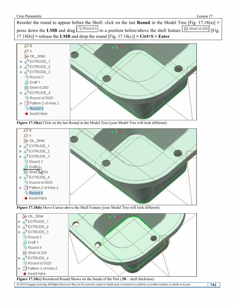
Reorder the round to appear before the Shell: click on the last Round in the Model Tree [Fig. 17.18(a)] >
press down the LMB and drag to a position before/above the shell feature [Fig. 17.18(b)] > release the LMB and drop the round [Fig. 17.18(c)] > Ctrl+S > Enter
Figure 17.18(a) Click on the last Round in the Model Tree (your Model Tree will look different)
Figure 17.18(b) Move Cursor above the Shell Feature (your Model Tree will look different)
Figure 17.18(c) Reordered Round Shows on the Inside of the Part (.50 – shell thickness)

Creo Parametric Lesson 17
©2013CengageLearning.AllRightsReserved.Maynotbescanned,copiedorduplicated,orpostedtoapubliclyaccessiblewebsite,inwholeorinpart. 746
You can also insert new features using the Model Tree. The arrow-shaped icon in the Model Tree indicates where features will be inserted upon creation and is by default at the end (or bottom) of the Model Tree.
By dragging the location of the insert node higher, so that its position is before existing features, you can insert a new feature at that stage of the model history. When the insert node is dropped at a new location, the model is rolled backward (suppressed) or forward in response to the insertion node being moved higher or lower. The Model Tree displays a small square (■) next to the features that are not active (suppressed).
The previous round was created at the wrong stage in the design sequence and then reordered. To eliminate the reordering of a feature, the remaining R.50 rounds will be created using Insert Mode with the Model Tree.
Insert Mode allows you to insert a feature at a previous stage of the design sequence. This is like going back into the past and doing something you wish you had done before--not possible with life, but with Creo Parametric less of a problem. Add the additional R.50 rounds.
Your Model Tree will look different.
In the Model Tree, click on [Fig. 17.19(a)] and drag it to a position before/above the shell feature
and drop [Fig. 17.19(b)] > spin the model > Refit
Figure 17.19(a) Insert Here Pointer (your Model Tree will Look Different)

Creo Parametric Lesson 17
©2013CengageLearning.AllRightsReserved.Maynotbescanned,copiedorduplicated,orpostedtoapubliclyaccessiblewebsite,inwholeorinpart. 747
Figure 17.19(b) Model Tree Shows Suppressed Features (your Model Tree will Look Different)
Create two separate rounds, click: Round > select the upper edge > Radius .50 > Enter [Fig. 17.20(a)] >
> Ctrl+C > Ctrl+V > select the front edge [Fig. 17.20(b)] > [Fig. 17.20(c)]
Figure 17.20(a) First Round Figure 17.20(b) Second Round

Creo Parametric Lesson 17
©2013CengageLearning.AllRightsReserved.Maynotbescanned,copiedorduplicated,orpostedtoapubliclyaccessiblewebsite,inwholeorinpart. 748
Figure 17.20(c) New Rounds Added (your Model Tree will look different)
Rotate the model > click on [Fig. 17.21(a)]
Figure 17.21(a) Rotate the Model (your Model Tree will Look Different)

Creo Parametric Lesson 17
©2013CengageLearning.AllRightsReserved.Maynotbescanned,copiedorduplicated,orpostedtoapubliclyaccessiblewebsite,inwholeorinpart. 749
Drag it to the bottom of the Model Tree list and drop [Fig. 17.21(b)] > select the propagated internal round surfaces in the model [Fig. 17.21(c)] > Ctrl+D > Ctrl+S > Enter > File > Manage File > Delete Old Versions > Enter > LMB to deselect
Figure 17.21(b) Drag and Drop Insert Here Node, All Features are Resumed (your Model Tree will look different)
Figure 17.21(c) Propagated Internal Rounds

Creo Parametric Lesson 17
©2013CengageLearning.AllRightsReserved.Maynotbescanned,copiedorduplicated,orpostedtoapubliclyaccessiblewebsite,inwholeorinpart. 750
Hide datum A, B and C > Model Tree off > View tab > off >
Ctrl+D > Render tab > Render Setup > Renderer > PhotoRender > set options as shown [Fig. 17.22(a)] > Close
Figure 17.22(a) Render Setup Dialog Box
Creo Parametric Lesson 17
©2013CengageLearning.AllRightsReserved.Maynotbescanned,copiedorduplicated,orpostedtoapubliclyaccessiblewebsite,inwholeorinpart. 751
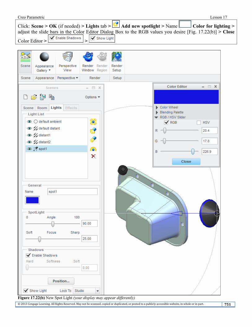
Click: Scene > OK (if needed) > Lights tab > Add new spotlight > Name Color for lighting > adjust the slide bars in the Color Editor Dialog Box to the RGB values you desire [Fig. 17.22(b)] > Close
Color Editor > >
Figure 17.22(b) New Spot Light (your display may appear differently)

Creo Parametric Lesson 17
©2013CengageLearning.AllRightsReserved.Maynotbescanned,copiedorduplicated,orpostedtoapubliclyaccessiblewebsite,inwholeorinpart. 752
Click: Add new distance light > Name Color for lighting > adjust the slide bars in the Color Editor Dialog Box to the RGB values you desire > Close Color Editor > move the light to a new position
[Fig. 17.22(c)] >
Figure 17.22(c) New Distant Light (your display may appear differently)

Creo Parametric Lesson 17
©2013CengageLearning.AllRightsReserved.Maynotbescanned,copiedorduplicated,orpostedtoapubliclyaccessiblewebsite,inwholeorinpart. 753
Click: Add new skylight > Name Color for lighting > adjust the slide bars in the Color Editor Dialog Box to the RGB values you desire > Close Color Editor > move the skylight [Fig. 17.22(d)] >
> > Close the Scenes Dialog Box
Figure 17.22(d) New Sky Light (your display may appear differently)

Creo Parametric Lesson 17
©2013CengageLearning.AllRightsReserved.Maynotbescanned,copiedorduplicated,orpostedtoapubliclyaccessiblewebsite,inwholeorinpart. 754
Click: > Shading With Reflections [Fig. 17.22(e)] > Ctrl+S > Enter
Figure 17.22(e) Shading With Reflections (the quality of your graphics card and graphics settings may prevent this display)

Creo Parametric Lesson 17
©2013CengageLearning.AllRightsReserved.Maynotbescanned,copiedorduplicated,orpostedtoapubliclyaccessiblewebsite,inwholeorinpart. 755
Click: File > Save as > Save a Copy > Type PDF U3D (*.pdf) [Fig. 17.23(a)] > OK [Fig. 17.23(b)] > OK
Figure 17.23(a) PDF U3D (*.pdf)
Figure 17.23(b) PDF U3D Export Settings

Creo Parametric Lesson 17
©2013CengageLearning.AllRightsReserved.Maynotbescanned,copiedorduplicated,orpostedtoapubliclyaccessiblewebsite,inwholeorinpart. 756
If needed- Click to activate > double-click on the model in the PDF [Fig. 17.23(c)]
Figure 17.23(c) Part Displayed in PDF Reader (make sure you get the latest available PDF Reader)

Creo Parametric Lesson 17
©2013CengageLearning.AllRightsReserved.Maynotbescanned,copiedorduplicated,orpostedtoapubliclyaccessiblewebsite,inwholeorinpart. 757
Click: Toggle Model Tree [Fig. 17.23(d)]
Figure 17.23(d) Model Tree Displayed

Creo Parametric Lesson 17
©2013CengageLearning.AllRightsReserved.Maynotbescanned,copiedorduplicated,orpostedtoapubliclyaccessiblewebsite,inwholeorinpart. 758
Press: LMB to rotate the part > Use Perspective Projection > off > Background Color (select a different color background) > press RMB to zoom in and out > expand the Tool Bar [Fig. 17.23(e)]
> Zoom > try other available commands > File > Properties > OK > File > Exit the PDF Reader
Figure 17.23(e) Expand 3D Tools

Creo Parametric Lesson 17
©2013CengageLearning.AllRightsReserved.Maynotbescanned,copiedorduplicated,orpostedtoapubliclyaccessiblewebsite,inwholeorinpart. 759
Click: > > Name oil_sink (do not use a space in the name) > > OK > OK > double-click on the SIZE: C tag in the lower left corner of your Graphics Window
> Sheet 1 C Size > > Browse > d.frm > Open > Preview > OK > double-click on the SCALE: tag in the lower left corner of the Graphics Window > type .50 > Enter > from the
Ribbon, (off) > rearrange the views as necessary [Fig. 17.24(a)] > Ctrl+S > Enter > View tab >
all off > in the Model Tree, select datums A, B, and C > RMB > Unhide in Model > Ctrl+S > OK > File > Prepare > Drawing Properties > Detail Options change > Option: type,
gtol > Enter > Value: > std_asme > Add/Change > Apply > Close > Close
Figure 17.24(a) Oil Sink Drawing

Creo Parametric Lesson 17
©2013CengageLearning.AllRightsReserved.Maynotbescanned,copiedorduplicated,orpostedtoapubliclyaccessiblewebsite,inwholeorinpart. 760
Click: Annotate tab > from the Ribbon, Show Model Annotations > select the front view > Ctrl > select
the top view > release the Ctrl key > tab > (select all) > Apply > tab > (select all) > Apply
> (close the dialog) > in the Drawing Tree, expand Annotations [Fig. 17.24(b)] > Layout tab > select the right view > press RMB > Delete > rearrange the remaining two views to fit the sheet > Change the sheet size, add views and sections to completely describe the part. Erase, delete, and reposition the axes and annotations as per ASME standards. [Figs. 17.24(c-d)] > use additional sheets as needed
Figure 17.24(b) Possible Detail Views and Dimensioning Scheme

Creo Parametric Lesson 17
©2013CengageLearning.AllRightsReserved.Maynotbescanned,copiedorduplicated,orpostedtoapubliclyaccessiblewebsite,inwholeorinpart. 761
Figure 17.24(c) Oil Sink Detail Drawing

Creo Parametric Lesson 17
©2013CengageLearning.AllRightsReserved.Maynotbescanned,copiedorduplicated,orpostedtoapubliclyaccessiblewebsite,inwholeorinpart. 762
Figure 17.24(d) Oil Sink Detail Drawing, Sheet 2- Additional Views
Press: Ctrl+S > Enter > File > Manage File > Delete Old Versions > Enter > File > Save As > Type > > Zip File (*.zip) > OK > upload the zip file to your course interface or attach to an email and send to your instructor and/or yourself > File > Close > File > Close > File > Exit > Yes Download projects from www.cad-resources.com > click on the image of your book cover.