s10, s12 series - lowaradoc.lowara.com/lowdata/doc/en/s-td-en.pdf · s12 series specifications ......
TRANSCRIPT
Lowara
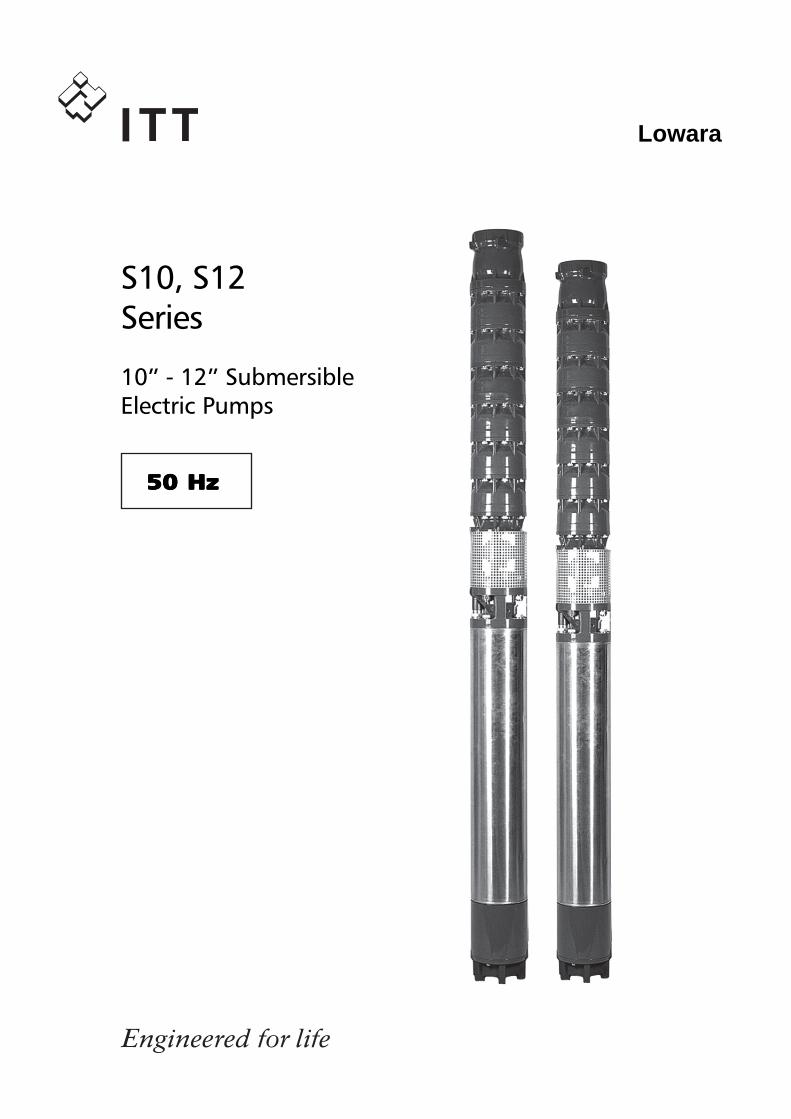
S10, S12Series
50 Hz50 Hz50 Hz50 Hz50 Hz
10” - 12” SubmersibleElectric Pumps
2
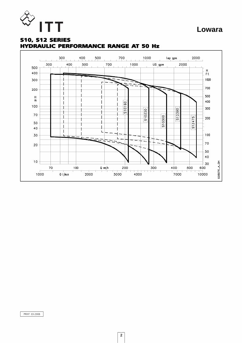
LowaraS10, S12 SERIESS10, S12 SERIESS10, S12 SERIESS10, S12 SERIESS10, S12 SERIESHYDRAHYDRAHYDRAHYDRAHYDRAULIC PERFORMANCE RANGE AULIC PERFORMANCE RANGE AULIC PERFORMANCE RANGE AULIC PERFORMANCE RANGE AULIC PERFORMANCE RANGE AT 50 HzT 50 HzT 50 HzT 50 HzT 50 Hz
PRINT 03-2008
3
Lowara
S10 Series Specifications .......................................................................................................................55555
Table of Materials ..................................................................................................................................66666
Hydraulic Performance Range, S10 Series 50 Hz ....................................................................................77777
S12 Series Specifications .................................................................................................................2525252525
Table of Materials ............................................................................................................................2626262626
Hydraulic Performance Range, S12 Series 50 Hz ..............................................................................2727272727
L6C Series Motors ............................................................................................................................4343434343
L6W Series Motors ..........................................................................................................................4747474747
L8W Series Motors ..........................................................................................................................5151515151
L10W Series Motors ........................................................................................................................5353535353
L12W Series Motors ........................................................................................................................5555555555
Accessories ......................................................................................................................................5757575757
Technical Appendix .........................................................................................................................7373737373
CONTENTSCONTENTSCONTENTSCONTENTSCONTENTS

4
Lowara
5
Lowara
APPLICAAPPLICAAPPLICAAPPLICAAPPLICATIONSTIONSTIONSTIONSTIONS• Water supply from deep wells.• Pressure boosting and water distribution in civil and industrial systems.• Supply of surge tanks and reservoirs.• Firefighting and washing systems.• Water table level control.• Irrigation.
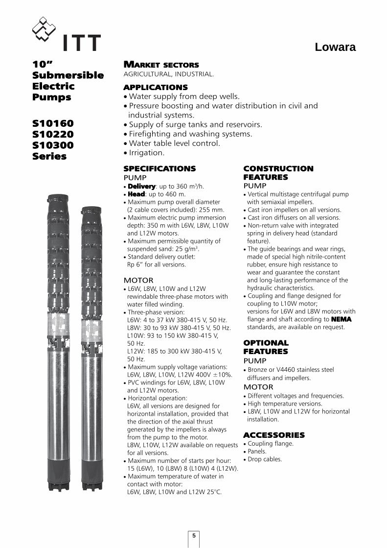
10”10”10”10”10”SubmersibleSubmersibleSubmersibleSubmersibleSubmersibleElectricElectricElectricElectricElectricPumpsPumpsPumpsPumpsPumps
MMMMMARKET SECTORSARKET SECTORSARKET SECTORSARKET SECTORSARKET SECTORSAGRICULTURAL, INDUSTRIAL.
S10160S10160S10160S10160S10160S10220S10220S10220S10220S10220S10300S10300S10300S10300S10300SeriesSeriesSeriesSeriesSeries
SPECIFICASPECIFICASPECIFICASPECIFICASPECIFICATIONSTIONSTIONSTIONSTIONSPUMP• DeliveryDeliveryDeliveryDeliveryDelivery: up to 360 m3/h.• HeadHeadHeadHeadHead: up to 460 m.• Maximum pump overall diameter (2 cable covers included): 255 mm.• Maximum electric pump immersion depth: 350 m with L6W, L8W, L10W and L12W motors.• Maximum permissible quantity of suspended sand: 25 g/m3.• Standard delivery outlet: Rp 6” for all versions.
MOTOR• L6W, L8W, L10W and L12W rewindable three-phase motors with water filled winding.• Three-phase version: L6W: 4 to 37 kW 380-415 V, 50 Hz. L8W: 30 to 93 kW 380-415 V, 50 Hz. L10W: 93 to 150 kW 380-415 V, 50 Hz. L12W: 185 to 300 kW 380-415 V, 50 Hz.• Maximum supply voltage variations: L6W, L8W, L10W, L12W 400V ±10%.• PVC windings for L6W, L8W, L10W and L12W motors.• Horizontal operation: L6W, all versions are designed for horizontal installation, provided that the direction of the axial thrust generated by the impellers is always from the pump to the motor. L8W, L10W, L12W available on requests for all versions.• Maximum number of starts per hour: 15 (L6W), 10 (L8W) 8 (L10W) 4 (L12W).• Maximum temperature of water in contact with motor: L6W, L8W, L10W and L12W 25°C.
CONSTRUCTIONCONSTRUCTIONCONSTRUCTIONCONSTRUCTIONCONSTRUCTIONFEAFEAFEAFEAFEATURESTURESTURESTURESTURESPUMP• Vertical multistage centrifugal pump with semiaxial impellers.• Cast iron impellers on all versions.• Cast iron diffusers on all versions.• Non-return valve with integrated spring in delivery head (standard feature).• The guide bearings and wear rings, made of special high nitrile-content rubber, ensure high resistance to wear and guarantee the constant and long-lasting performance of the hydraulic characteristics.• Coupling and flange designed for coupling to L10W motor; versions for L6W and L8W motors with flange and shaft according to NEMANEMANEMANEMANEMA standards, are available on request.
OPTIONALOPTIONALOPTIONALOPTIONALOPTIONALFEAFEAFEAFEAFEATURESTURESTURESTURESTURESPUMP• Bronze or V4460 stainless steel diffusers and impellers.MOTOR• Different voltages and frequencies.• High temperature versions.• L8W, L10W and L12W for horizontal installation.
ACCESACCESACCESACCESACCESSORIESSORIESSORIESSORIESSORIES• Coupling flange.• Panels.• Drop cables.
6
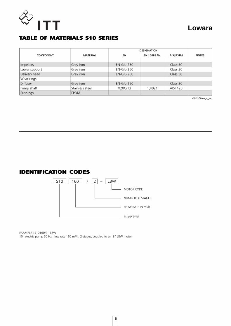
LowaraTTTTTABLE OF MAABLE OF MAABLE OF MAABLE OF MAABLE OF MATERIALS S10 SERIESTERIALS S10 SERIESTERIALS S10 SERIESTERIALS S10 SERIESTERIALS S10 SERIES
L8WS10 /
NUMBER OF STAGES
FLOW RATE IN m3/h
MOTOR CODE
160 2
PUMP TYPE
EXAMPLE : S10160/2 - L8W10” electric pump 50 Hz, flow rate 160 m3/h, 2 stages, coupled to an 8” L8W motor.
IDENTIFICAIDENTIFICAIDENTIFICAIDENTIFICAIDENTIFICATION CODESTION CODESTION CODESTION CODESTION CODES
TABELLA MATERIALI S10
COMPONENT MATERIAL EN EN 10088 Nr. AISI/ASTM NOTES
Impellers Grey iron EN-GJL-250 Class 30
Lower support Grey iron EN-GJL-250 Class 30
Delivery head Grey iron EN-GJL-250 Class 30
Wear rings -
Diffuser Grey iron EN-GJL-250 Class 30
Pump shaft Stainless steel X20Cr13 1,4021 AISI 420
Bushings EPDM
s10-2p50-en_a_tm
DESIGNATION
7
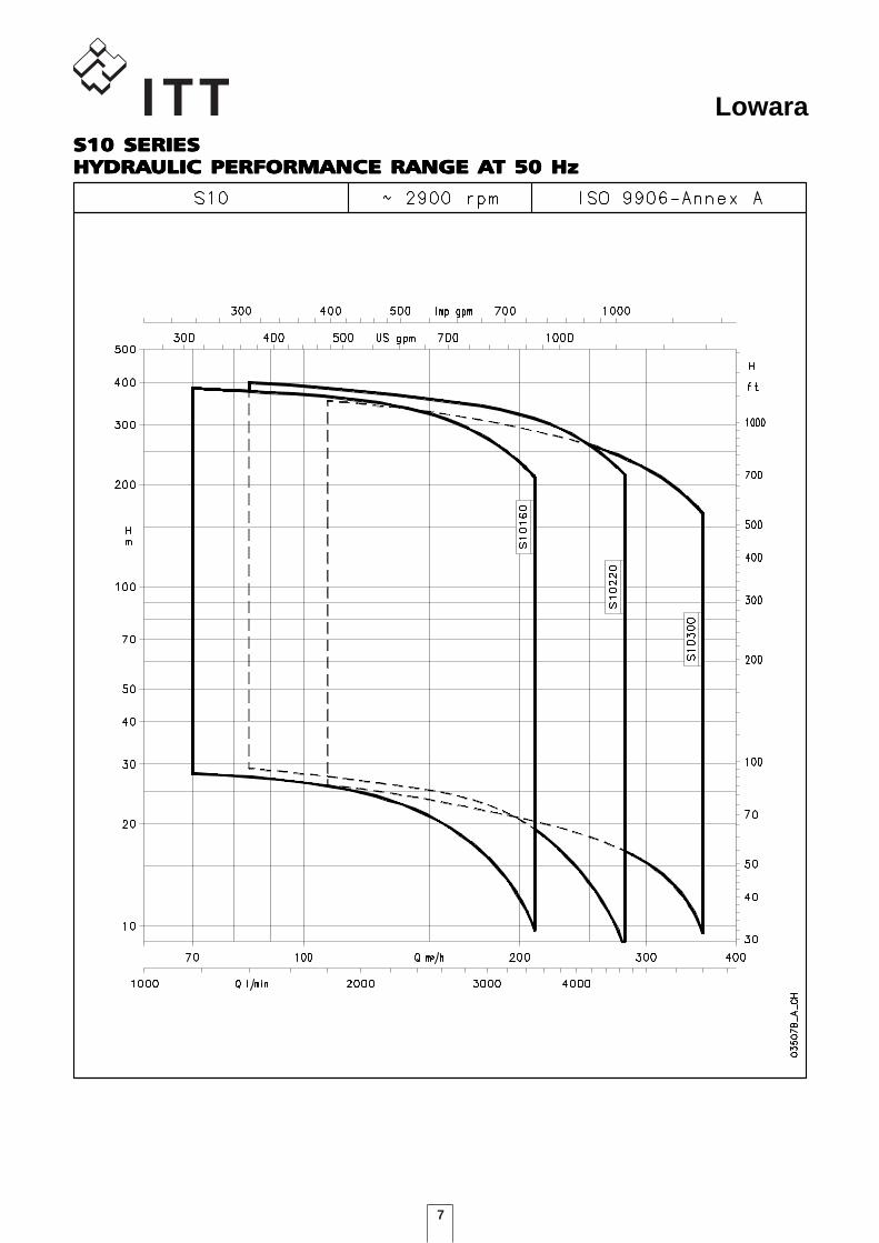
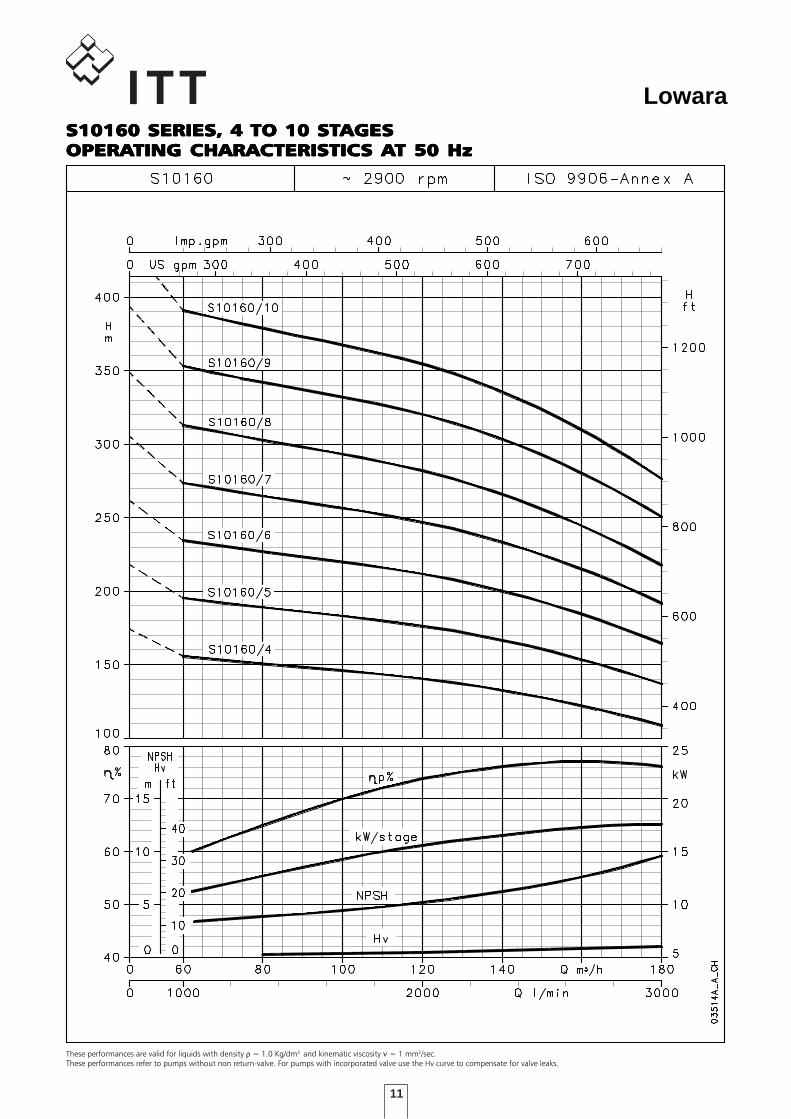
LowaraS10 SERIESS10 SERIESS10 SERIESS10 SERIESS10 SERIESHYDRAHYDRAHYDRAHYDRAHYDRAULIC PERFORMANCE RANGE AULIC PERFORMANCE RANGE AULIC PERFORMANCE RANGE AULIC PERFORMANCE RANGE AULIC PERFORMANCE RANGE AT 50 HzT 50 HzT 50 HzT 50 HzT 50 Hz
8
Lowara
DIMENSIONS AND WEIGHTSDIMENSIONS AND WEIGHTSDIMENSIONS AND WEIGHTSDIMENSIONS AND WEIGHTSDIMENSIONS AND WEIGHTS
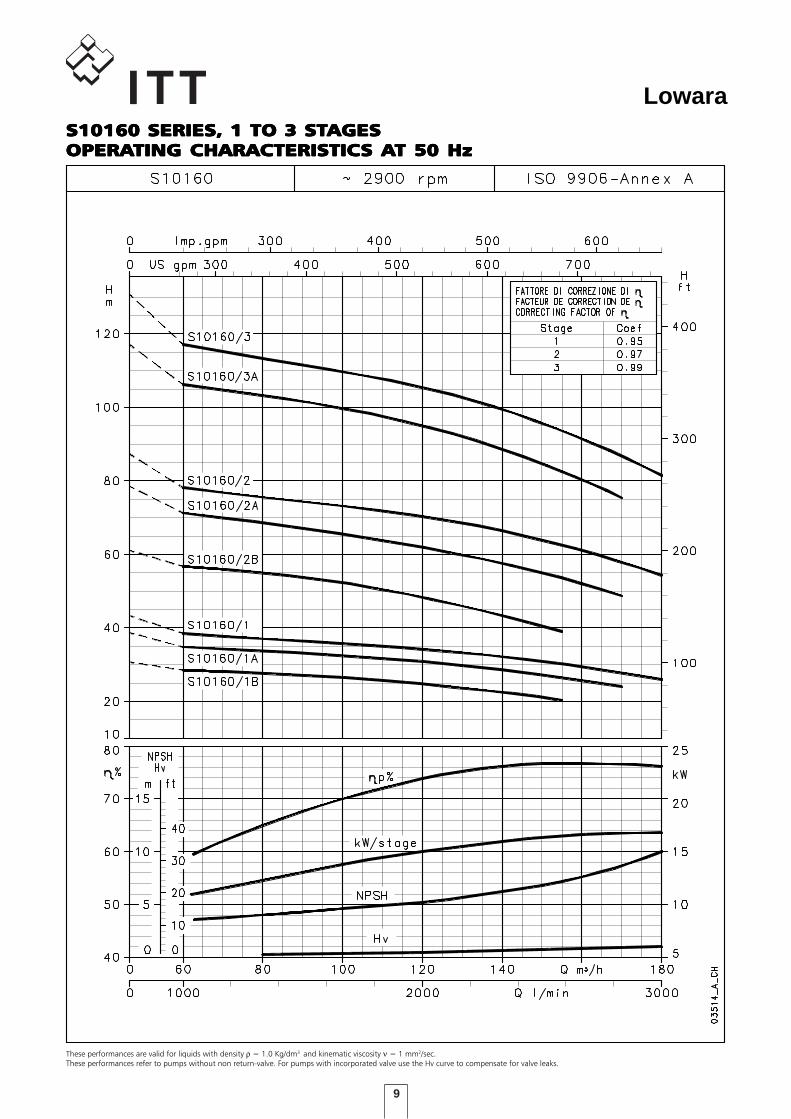
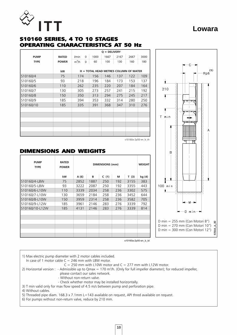
S10160 SERIES, 1 TO 3 STS10160 SERIES, 1 TO 3 STS10160 SERIES, 1 TO 3 STS10160 SERIES, 1 TO 3 STS10160 SERIES, 1 TO 3 STAGESAGESAGESAGESAGESOPERAOPERAOPERAOPERAOPERATING CHARACTERISTICTING CHARACTERISTICTING CHARACTERISTICTING CHARACTERISTICTING CHARACTERISTICS AS AS AS AS AT 50 HzT 50 HzT 50 HzT 50 HzT 50 HzTABELLA DI PRESTAZIONI IDRAULICHE SERIE S10160 2 poli 50 Hz
PUMP RATED l/min 0l/min 0 10001000 16671667 21672167 26672667 30003000
TYPE POWER m3/h 0/h 0 6060 100100 130130 160160 180180
kW
S10160/1 18,5 43 38 36 33 29 26
S10160/2 37 87 78 73 68 61 54
S10160/3 55 131 117 110 103 92 82
l/min 0l/min 0 10001000 15001500 20002000 23332333 28332833
m3/h 0m3/h 0 60 90 120120 140140 170170
S10160/1A 15 38 35 33 31 28 24
S10160/2A 30 78 72 67 62 58 49
S10160/3A 45 117 107 102 95 88 76
l/min 0l/min 0 10001000 13331333 16671667 20002000 25832583
m3/h 0m3/h 0 60 80 100100 120120 155155
S10160/1B 11 31 28 28 26 25 21
S10160/2B 22 61 57 55 52 48 39
s10160-2p50-en_b_th
H = TOTAL HEAD METRES COLUMN OF WATER
Q = DELIVERY
DIMENSIONI E PESI SERIE S10160 2 poli 50 Hz
PUMP RATED
TYPE POWER
kW A (6) B C (1) M T (3) kg (4)
S10160/1B-L6W 11 1505 1050 250 144 2323 118
S10160/1A-L6W 15 1615 1160 250 144 2433 130
S10160/1-L6W 18,5 1685 1230 250 144 2503 138
S10160/2B-L6W 22 1895 1270 250 144 2543 163
S10160/2A-L6W 30 2103 1478 250 144 2751 180
S10160/2-L6W 37 2142 1628 250 144 2901 194
S10160/3A-L8W 45 2322 1527 250 192 2795 289
S10160/3-L8W 55 2452 1657 250 192 2925 315
s10160-2p50-en_b_td
WEIGHTDIMENSIONS (mm)
1) Max electric pump diameter with 2 motor cables included. In case of 1 motor cable C = 246 mm with L6W motor. C = 246 mm with L8W motor.2) Horizontal version : - Admissible up to Qmax = 170 m3/h. (Only for full impeller diameter); for reduced impeller, please contact our sales network. - Without non-return valve. - Check whether motor may be installed horizontally.3) T min valid only for max flow speed of 4.5 m/s between pump and perforation pipe.4) Without cables.5) Threaded pipe diam. 168.3 x 7.1mm L=143 available on request, API thred available on request.6) For pumps without non-return valve, reduce by 210 mm.
D min = 255 mm.
9
Lowara
These performances are valid for liquids with density ρ = 1.0 Kg/dm3 and kinematic viscosity ν = 1 mm2/sec.These performances refer to pumps without non return-valve. For pumps with incorporated valve use the Hv curve to compensate for valve leaks.
S10160 SERIES, 1 TO 3 STS10160 SERIES, 1 TO 3 STS10160 SERIES, 1 TO 3 STS10160 SERIES, 1 TO 3 STS10160 SERIES, 1 TO 3 STAGESAGESAGESAGESAGESOPERAOPERAOPERAOPERAOPERATING CHARACTERISTICTING CHARACTERISTICTING CHARACTERISTICTING CHARACTERISTICTING CHARACTERISTICS AS AS AS AS AT 50 HzT 50 HzT 50 HzT 50 HzT 50 Hz
10
Lowara
DIMENSIONS AND WEIGHTSDIMENSIONS AND WEIGHTSDIMENSIONS AND WEIGHTSDIMENSIONS AND WEIGHTSDIMENSIONS AND WEIGHTS
TABELLA DI PRESTAZIONI IDRAULICHE SERIE S10160 2 poli 50 Hz
PUMP RATED l/min 0l/min 0 10001000 16671667 21672167 26672667 30003000
TYPE POWER m3/h 0/h 0 6060 100100 130130 160160 180180
kW
S10160/4 75 174 156 146 137 122 109
S10160/5 93 218 196 184 173 153 137
S10160/6 110 262 235 220 207 184 164
S10160/7 130 305 273 257 241 215 192
S10160/8 150 350 313 294 275 245 217
S10160/9 185 394 353 332 314 280 250
S10160/10 185 335 391 368 347 310 276
s10160a-2p50-en_b_th
H = TOTAL HEAD METRES COLUMN OF WATER
Q = DELIVERY
DIMENSIONI E PESI SERIE S10160 2 poli 50 Hz
PUMP RATED
TYPE POWER
kW A (6) B C (1) M T (3) kg (4)
S10160/4-L8W 75 2852 1887 250 192 3155 383
S10160/5-L8W 93 3222 2087 250 192 3355 443
S10160/6-L10W 110 3339 2034 258 236 3302 575
S10160/7-L10W 130 3659 2184 258 236 3452 644
S10160/8-L10W 150 3959 2314 258 236 3582 705
S10160/9-L12W 185 3961 2146 283 276 3339 792
S10160/10-L12W 185 4131 2146 283 276 3339 814
s10160a-2p50-en_b_td
WEIGHTDIMENSIONS (mm)
1) Max electric pump diameter with 2 motor cables included. In case of 1 motor cable C = 246 mm with L8W motor. C = 250 mm with L10W motor and C = 277 mm with L12W motor.2) Horizontal version : - Admissible up to Qmax = 170 m3/h. (Only for full impeller diameter); for reduced impeller, please contact our sales network. - Without non-return valve. - Check whether motor may be installed horizontally.3) T min valid only for max flow speed of 4.5 m/s between pump and perforation pipe.4) Without cables.5) Threaded pipe diam. 168.3 x 7.1mm L=143 available on request, API thred available on request.6) For pumps without non-return valve, reduce by 210 mm.
D min = 255 mm (Con Motori 8”)D min = 270 mm (Con Motori 10”)D min = 300 mm (Con Motori 12”)
S10160 SERIES, 4 TO 10 STS10160 SERIES, 4 TO 10 STS10160 SERIES, 4 TO 10 STS10160 SERIES, 4 TO 10 STS10160 SERIES, 4 TO 10 STAGESAGESAGESAGESAGESOPERAOPERAOPERAOPERAOPERATING CHARACTERISTICTING CHARACTERISTICTING CHARACTERISTICTING CHARACTERISTICTING CHARACTERISTICS AS AS AS AS AT 50 HzT 50 HzT 50 HzT 50 HzT 50 Hz
11
Lowara
These performances are valid for liquids with density ρ = 1.0 Kg/dm3 and kinematic viscosity ν = 1 mm2/sec.These performances refer to pumps without non return-valve. For pumps with incorporated valve use the Hv curve to compensate for valve leaks.
S10160 SERIES, 4 TO 10 STS10160 SERIES, 4 TO 10 STS10160 SERIES, 4 TO 10 STS10160 SERIES, 4 TO 10 STS10160 SERIES, 4 TO 10 STAGESAGESAGESAGESAGESOPERAOPERAOPERAOPERAOPERATING CHARACTERISTICTING CHARACTERISTICTING CHARACTERISTICTING CHARACTERISTICTING CHARACTERISTICS AS AS AS AS AT 50 HzT 50 HzT 50 HzT 50 HzT 50 Hz
12
Lowara
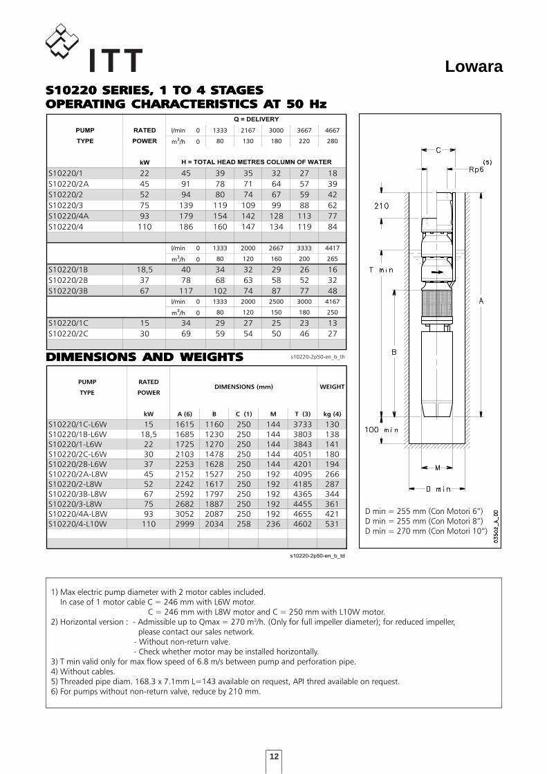
TABELLA DI PRESTAZIONI IDRAULICHE SERIE S10220 2 poli 50 Hz
PUMP RATED l/min 0l/min 0 1333 2167 3000 3667 4667
TYPE POWER m3/h 0 80 130 180 220 280
kW
S10220/1 22 45 39 35 32 27 18
S10220/2A 45 91 78 71 64 57 39
S10220/2 52 94 80 74 67 59 42
S10220/3 75 139 119 109 99 88 62
S10220/4A 93 179 154 142 128 113 77
S10220/4 110 186 160 147 134 119 84
l/min 0l/min 0 1333 2000 2667 3333 4417
m3/h 0 80 120 160 200 265
S10220/1B 18,5 40 34 32 29 26 16
S10220/2B 37 78 68 63 58 52 32
S10220/3B 67 117 102 74 87 77 48
l/min 0l/min 0 1333 2000 2500 3000 4167
m3/h 0 80 120 150 180 250
S10220/1C 15 34 29 27 25 23 13
S10220/2C 30 69 59 54 50 46 27
s10220-2p50-en_b_th
H = TOTAL HEAD METRES COLUMN OF WATER
Q = DELIVERY
DIMENSIONI E PESI SERIE S10220 2 poli 50 Hz
PUMP RATED
TYPE POWER
kW A (6) B C (1) M T (3) kg (4)
S10220/1C-L6W 15 1615 1160 250 144 3733 130
S10220/1B-L6W 18,5 1685 1230 250 144 3803 138
S10220/1-L6W 22 1725 1270 250 144 3843 141
S10220/2C-L6W 30 2103 1478 250 144 4051 180
S10220/2B-L6W 37 2253 1628 250 144 4201 194
S10220/2A-L8W 45 2152 1527 250 192 4095 266
S10220/2-L8W 52 2242 1617 250 192 4185 287
S10220/3B-L8W 67 2592 1797 250 192 4365 344
S10220/3-L8W 75 2682 1887 250 192 4455 361
S10220/4A-L8W 93 3052 2087 250 192 4655 421
S10220/4-L10W 110 2999 2034 258 236 4602 531
s10220-2p50-en_b_td
WEIGHTDIMENSIONS (mm)
1) Max electric pump diameter with 2 motor cables included. In case of 1 motor cable C = 246 mm with L6W motor. C = 246 mm with L8W motor and C = 250 mm with L10W motor.2) Horizontal version : - Admissible up to Qmax = 270 m3/h. (Only for full impeller diameter); for reduced impeller, please contact our sales network. - Without non-return valve. - Check whether motor may be installed horizontally.3) T min valid only for max flow speed of 6.8 m/s between pump and perforation pipe.4) Without cables.5) Threaded pipe diam. 168.3 x 7.1mm L=143 available on request, API thred available on request.6) For pumps without non-return valve, reduce by 210 mm.
DIMENSIONS AND WEIGHTSDIMENSIONS AND WEIGHTSDIMENSIONS AND WEIGHTSDIMENSIONS AND WEIGHTSDIMENSIONS AND WEIGHTS
D min = 255 mm (Con Motori 6”)D min = 255 mm (Con Motori 8”)D min = 270 mm (Con Motori 10”)
S10220 SERIES, 1 TO 4 STS10220 SERIES, 1 TO 4 STS10220 SERIES, 1 TO 4 STS10220 SERIES, 1 TO 4 STS10220 SERIES, 1 TO 4 STAGESAGESAGESAGESAGESOPERAOPERAOPERAOPERAOPERATING CHARACTERISTICTING CHARACTERISTICTING CHARACTERISTICTING CHARACTERISTICTING CHARACTERISTICS AS AS AS AS AT 50 HzT 50 HzT 50 HzT 50 HzT 50 Hz
13
Lowara
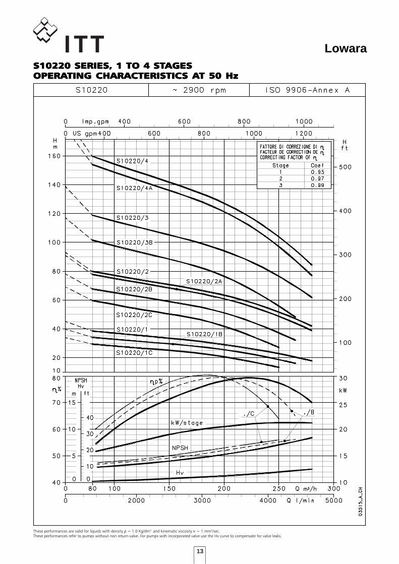
These performances are valid for liquids with density ρ = 1.0 Kg/dm3 and kinematic viscosity ν = 1 mm2/sec.These performances refer to pumps without non return-valve. For pumps with incorporated valve use the Hv curve to compensate for valve leaks.
S10220 SERIES, 1 TO 4 STS10220 SERIES, 1 TO 4 STS10220 SERIES, 1 TO 4 STS10220 SERIES, 1 TO 4 STS10220 SERIES, 1 TO 4 STAGESAGESAGESAGESAGESOPERAOPERAOPERAOPERAOPERATING CHARACTERISTICTING CHARACTERISTICTING CHARACTERISTICTING CHARACTERISTICTING CHARACTERISTICS AS AS AS AS AT 50 HzT 50 HzT 50 HzT 50 HzT 50 Hz
14
Lowara
DIMENSIONS AND WEIGHTSDIMENSIONS AND WEIGHTSDIMENSIONS AND WEIGHTSDIMENSIONS AND WEIGHTSDIMENSIONS AND WEIGHTS
TABELLA DI PRESTAZIONI IDRAULICHE SERIE S10220 2 poli 50 Hz
PUMP RATED l/min 0 1333 2167 3000 3667 4667
TYPE POWER m3/h 0 80 130 180 220 280
kW
S10220/5A 110 218 188 171 155 135 89
S10220/5 130 233 199 183 167 148 104
S10220/6A 150 260 224 207 185 163 107
S10220/6 150 278 239 219 198 177 125
S10220/7A 185 304 262 238 215 188 123
S10220/7 185 325 280 257 235 209 148
S10220/8 185 370 318 293 267 237 167
S10220/9 220 420 360 333 302 271 193
S10220/10A 220 436 377 347 313 276 184
S10220/10 260 466 402 370 337 302 215
s10220a-2p50-en_b_th
H = TOTAL HEAD METRES COLUMN OF WATER
Q = DELIVERY
DIMENSIONI E PESI SERIE S10220 2 poli 50 Hz
PUMP RATED
TYPE POWER
kW A (6) B C (1) M T (3) kg (4)
S10220/5A-L10W 110 3169 2034 258 236 4602 553
S10220/5-L10W 130 3319 2184 258 236 4752 600
S10220/6A-L10W 150 3619 2314 258 236 4882 661
S10220/6-L10W 150 3619 2314 258 236 4882 661
S10220/7A-L12W 185 3621 2146 283 276 4639 748
S10220/7-L12W 185 3621 2146 283 276 4639 748
S10220/8-L12W 185 3791 2146 283 276 4639 770
S10220/9-L12W 220 4111 2296 283 276 4789 856
S10220/10A-L12W 220 4281 2296 283 276 4789 878
S10220/10-L12W 260 4431 2446 283 276 4939 942
s10220a-2p50-en_b_td
WEIGHTDIMENSIONS (mm)
1) Max electric pump diameter with 2 motor cables included. In case of 1 motor cable C = 250 mm with L10W motor. C = 277 mm with L12W motor.2) Horizontal version : - Admissible up to Qmax = 270 m3/h. (Only for full impeller diameter); for reduced impeller, please contact our sales network. - Without non-return valve. - Check whether motor may be installed horizontally.3) T min valid only for max flow speed of 6.8 m/s between pump and perforation pipe.4) Without cables.5) Threaded pipe diam. 168.3 x 7.1mm L=143 available on request, API thred available on request.6) For pumps without non-return valve, reduce by 210 mm.
D min = 270 mm (with 10” Motors)D min = 300 mm (with 12” Motors)
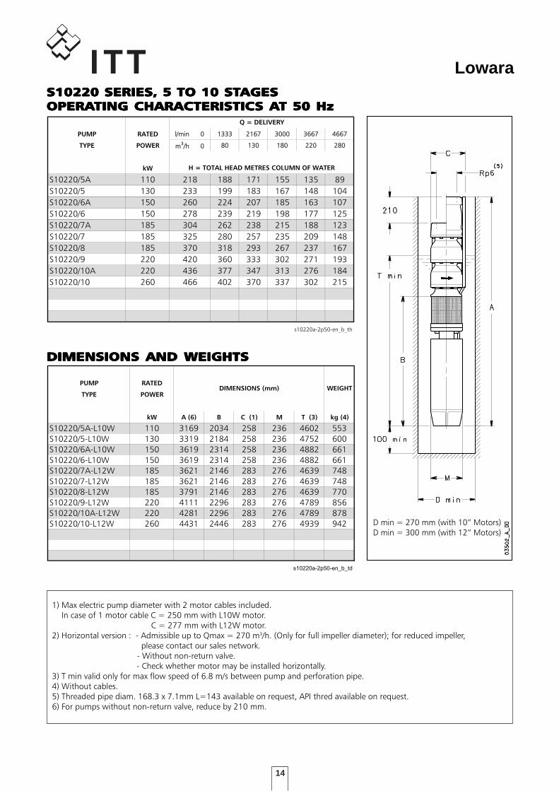
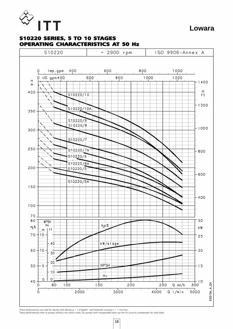
S10220 SERIES, 5 TO 10 STS10220 SERIES, 5 TO 10 STS10220 SERIES, 5 TO 10 STS10220 SERIES, 5 TO 10 STS10220 SERIES, 5 TO 10 STAGESAGESAGESAGESAGESOPERAOPERAOPERAOPERAOPERATING CHARACTERISTICTING CHARACTERISTICTING CHARACTERISTICTING CHARACTERISTICTING CHARACTERISTICS AS AS AS AS AT 50 HzT 50 HzT 50 HzT 50 HzT 50 Hz
15
Lowara
These performances are valid for liquids with density ρ = 1.0 Kg/dm3 and kinematic viscosity ν = 1 mm2/sec.These performances refer to pumps without non return-valve. For pumps with incorporated valve use the Hv curve to compensate for valve leaks.
S10220 SERIES, 5 TO 10 STS10220 SERIES, 5 TO 10 STS10220 SERIES, 5 TO 10 STS10220 SERIES, 5 TO 10 STS10220 SERIES, 5 TO 10 STAGESAGESAGESAGESAGESOPERAOPERAOPERAOPERAOPERATING CHARACTERISTICTING CHARACTERISTICTING CHARACTERISTICTING CHARACTERISTICTING CHARACTERISTICS AS AS AS AS AT 50 HzT 50 HzT 50 HzT 50 HzT 50 Hz
16
Lowara
DIMENSIONS AND WEIGHTSDIMENSIONS AND WEIGHTSDIMENSIONS AND WEIGHTSDIMENSIONS AND WEIGHTSDIMENSIONS AND WEIGHTS
TABELLA DI PRESTAZIONI IDRAULICHE SERIE S10300 2 poli 50 Hz
PUMP RATED l/min 0l/min 0 20002000 30003000 40004000 48334833 60006000
TYPE POWER m3/h 0/h 0 120120 180180 240240 290290 360360
kW
S10300/1 26 43 34 30 27 23 16
S10300/2 55 85 68 60 54 48 32
S10300/3 75 127 103 91 82 73 48
l/min 0l/min 0 20002000 30003000 40004000 48334833 56675667
m3/h 0/h 0 120120 180180 240240 290290 340340
S10300/1A 22 37 29 25 23 19 14
S10300/2A 45 75 60 52 47 41 31
l/min 0l/min 0 20002000 30003000 36673667 45004500 53335333
m3/h 0/h 0 120120 180180 220220 270270 320320
S10300/1B 18,5 32 25 22 20 18 14
S10300/2B 37 65 52 44 42 38 30
s10300-2p50-en_b_th
H = TOTAL HEAD METRES COLUMN OF WATER
Q = DELIVERY
DIMENSIONI E PESI SERIE S10300 2 poli 50 Hz
PUMP RATED
TYPE POWER
kW A (6) B C (1) M T (3) kg (4)
S10300/1B-L6W 18,5 1685 1230 250 144 3803 138
S10300/1A-L6W 22 1725 1270 250 144 3843 141
S10300/1-L6W 26 1853 1398 250 144 3971 150
S10300/2B-L6W 37 2253 1628 250 144 4201 194
S10300/2A-L8W 45 2152 1527 250 192 4095 267
S10300/2-L8W 55 2282 1657 250 192 4225 292
S10300/3-L8W 75 2682 1887 250 192 4455 360
s10300-2p50-en_b_td
WEIGHTDIMENSIONS (mm)
1) Max electric pump diameter with 2 motor cables included. In case of 1 motor cable C = 246 mm with L6W motor. C = 246 mm with L8W motor.2) Horizontal version : - Admissible up to Qmax = 340m3/h. (Only for full impeller diameter); for reduced impeller, please contact our sales network. - Without non-return valve. - Check whether motor may be installed horizontally.3) T min valid only for max flow speed of 6.8 m/s between pump and perforation pipe.4) Without cables.5) Threaded pipe diam. 168.3 x 7.1mm L=143 available on request, API thred available on request.6) For pumps without non-return valve, reduce by 210 mm.
D min = 255 mm (with 6” Motors)D min = 255 mm (with 8” Motors)
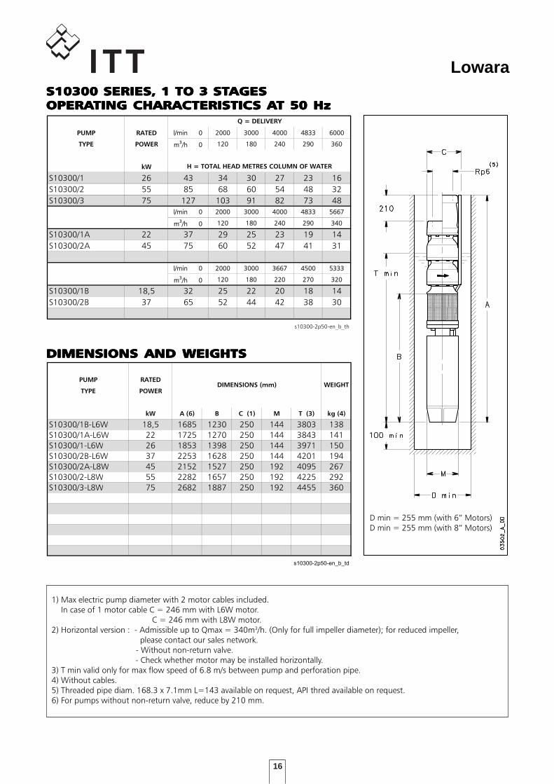
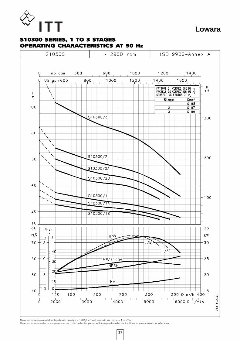
S10300 SERIES, 1 TO 3 STS10300 SERIES, 1 TO 3 STS10300 SERIES, 1 TO 3 STS10300 SERIES, 1 TO 3 STS10300 SERIES, 1 TO 3 STAGESAGESAGESAGESAGESOPERAOPERAOPERAOPERAOPERATING CHARACTERISTICTING CHARACTERISTICTING CHARACTERISTICTING CHARACTERISTICTING CHARACTERISTICS AS AS AS AS AT 50 HzT 50 HzT 50 HzT 50 HzT 50 Hz
17
Lowara
These performances are valid for liquids with density ρ = 1.0 Kg/dm3 and kinematic viscosity ν = 1 mm2/sec.These performances refer to pumps without non return-valve. For pumps with incorporated valve use the Hv curve to compensate for valve leaks.
S10300 SERIES, 1 TO 3 STS10300 SERIES, 1 TO 3 STS10300 SERIES, 1 TO 3 STS10300 SERIES, 1 TO 3 STS10300 SERIES, 1 TO 3 STAGESAGESAGESAGESAGESOPERAOPERAOPERAOPERAOPERATING CHARACTERISTICTING CHARACTERISTICTING CHARACTERISTICTING CHARACTERISTICTING CHARACTERISTICS AS AS AS AS AT 50 HzT 50 HzT 50 HzT 50 HzT 50 Hz
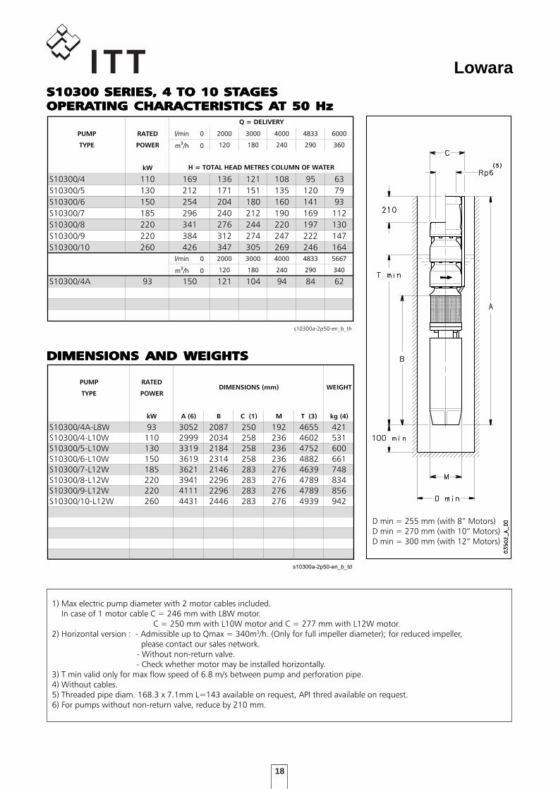
18
Lowara
DIMENSIONS AND WEIGHTSDIMENSIONS AND WEIGHTSDIMENSIONS AND WEIGHTSDIMENSIONS AND WEIGHTSDIMENSIONS AND WEIGHTS
TABELLA DI PRESTAZIONI IDRAULICHE SERIE S10300 2 poli 50 Hz
PUMP RATED l/min 0l/min 0 20002000 30003000 40004000 48334833 60006000
TYPE POWER m3/h 0/h 0 120120 180180 240240 290290 360360
kW
S10300/4 110 169 136 121 108 95 63
S10300/5 130 212 171 151 135 120 79
S10300/6 150 254 204 180 160 141 93
S10300/7 185 296 240 212 190 169 112
S10300/8 220 341 276 244 220 197 130
S10300/9 220 384 312 274 247 222 147
S10300/10 260 426 347 305 269 246 164
l/min 0l/min 0 20002000 30003000 40004000 48334833 56675667
m3/h 0/h 0 120120 180180 240240 290290 340340
S10300/4A 93 150 121 104 94 84 62
s10300a-2p50-en_b_th
H = TOTAL HEAD METRES COLUMN OF WATER
Q = DELIVERY
DIMENSIONI E PESI SERIE S10300 2 poli 50 Hz
PUMP RATED
TYPE POWER
kW A (6) B C (1) M T (3) kg (4)
S10300/4A-L8W 93 3052 2087 250 192 4655 421
S10300/4-L10W 110 2999 2034 258 236 4602 531
S10300/5-L10W 130 3319 2184 258 236 4752 600
S10300/6-L10W 150 3619 2314 258 236 4882 661
S10300/7-L12W 185 3621 2146 283 276 4639 748
S10300/8-L12W 220 3941 2296 283 276 4789 834
S10300/9-L12W 220 4111 2296 283 276 4789 856
S10300/10-L12W 260 4431 2446 283 276 4939 942
s10300a-2p50-en_b_td
WEIGHTDIMENSIONS (mm)
1) Max electric pump diameter with 2 motor cables included. In case of 1 motor cable C = 246 mm with L8W motor. C = 250 mm with L10W motor and C = 277 mm with L12W motor.2) Horizontal version : - Admissible up to Qmax = 340m3/h. (Only for full impeller diameter); for reduced impeller, please contact our sales network. - Without non-return valve. - Check whether motor may be installed horizontally.3) T min valid only for max flow speed of 6.8 m/s between pump and perforation pipe.4) Without cables.5) Threaded pipe diam. 168.3 x 7.1mm L=143 available on request, API thred available on request.6) For pumps without non-return valve, reduce by 210 mm.
D min = 255 mm (with 8” Motors)D min = 270 mm (with 10” Motors)D min = 300 mm (with 12” Motors)
S10300 SERIES, 4 TO 10 STS10300 SERIES, 4 TO 10 STS10300 SERIES, 4 TO 10 STS10300 SERIES, 4 TO 10 STS10300 SERIES, 4 TO 10 STAGESAGESAGESAGESAGESOPERAOPERAOPERAOPERAOPERATING CHARACTERISTICTING CHARACTERISTICTING CHARACTERISTICTING CHARACTERISTICTING CHARACTERISTICS AS AS AS AS AT 50 HzT 50 HzT 50 HzT 50 HzT 50 Hz
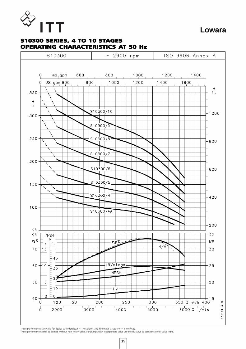
19
Lowara
These performances are valid for liquids with density ρ = 1.0 Kg/dm3 and kinematic viscosity ν = 1 mm2/sec.These performances refer to pumps without non return-valve. For pumps with incorporated valve use the Hv curve to compensate for valve leaks.
S10300 SERIES, 4 TO 10 STS10300 SERIES, 4 TO 10 STS10300 SERIES, 4 TO 10 STS10300 SERIES, 4 TO 10 STS10300 SERIES, 4 TO 10 STAGESAGESAGESAGESAGESOPERAOPERAOPERAOPERAOPERATING CHARACTERISTICTING CHARACTERISTICTING CHARACTERISTICTING CHARACTERISTICTING CHARACTERISTICS AS AS AS AS AT 50 HzT 50 HzT 50 HzT 50 HzT 50 Hz
20
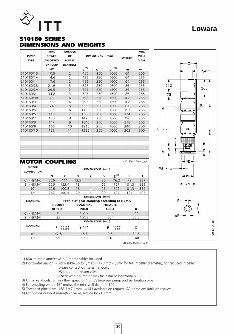
LowaraS10160 SERIESS10160 SERIESS10160 SERIESS10160 SERIESS10160 SERIESDIMENSIONS AND WEIGHTSDIMENSIONS AND WEIGHTSDIMENSIONS AND WEIGHTSDIMENSIONS AND WEIGHTSDIMENSIONS AND WEIGHTSDIMENSIONI E PESI SERIE S10160 A 2 Poli 50 Hz
MAX NUMBER MIN.
PUMP POWER OF WELL
TYPE ABSORBED PUMPS DIAM.
BY PUMP BEARINGS
kW L(6)
C (1)
U (3) kg mm
S10160/1B 10,9 2 455 250 1600 64 255
S10160/1A 14,6 2 455 250 1600 64 255
S10160/1 17,6 2 455 250 1600 64 255
S10160/2B 21,6 3 625 250 1600 86 255
S10160/2A 29,5 3 625 250 1600 86 255
S10160/2 34,8 3 625 250 1600 86 255
S10160/3A 45 4 795 250 1600 108 255
S10160/3 55 4 795 250 1600 108 255
S10160/4 74 5 965 250 1600 130 255
S10160/5 90 6 1135 250 1600 152 255
S10160/6 110 7 1305 250 1600 174 255
S10160/7 130 8 1475 250 1600 196 255
S10160/8 147 9 1645 250 1600 218 255
S10160/9 166 10 1815 255 1600 240 300
S10160/10 183 11 1985 255 1600 262 300
s10160p-2p50-en_a_td
DIMENSIONS (mm)WEIGHT
1) Max pump diameter with 2 motor cables included.2) Horizontal version : - Admissible up to Qmax = 170 m3/h. (Only for full impeller diameter); for reduced impeller, please contact our sales network. - Without non-return valve. - Check whether motor may be installed horizontally.3) U min valid only for max flow speed of 4,5 m/s between pump and perforation pipe.4) For coupling with a 12” motor, the min. well diam. = 300 mm.5) Threaded pipe diam. 168.3 x 7.1mm L=143 available on request, API thred available on request.6) For pumps without non-return valve, reduce by 210 mm.
DIMENSIONI ACCOPPIAMENTO MOTORI SERIE S10 2 Poli 50 H
MOTOR
CONNECTION
N k d z b EH7 R l
6" (NEMA) 226 111 13,5 4 20 76,2 73 237
8" (NEMA) 226 152,4 18 4 25 127 101,3 332
10" 226 190,5 18 4 25 127 101,3 332
12" 232 190,5 20 4 20 127 127 407
COUPLING
6" (NEMA)
8" (NEMA)
COUPLING +0.084 +0.05+0.059 +0.02
10"
12"
s10-mtcn-2p50-en_a_td
DIMENSIONS (mm)
NUMBER
OF TEETH
DIMENSIONS (mm)
Profile of gear coupling according to NEMA
DIAMETRAL
PITCH
PRESSURE
ANGLE
9,5
16
84,5
108
42,8
55
H+0.1
48,3
59,3
DIMENSIONS (mm)
F P X
X
15
23
16/32
16/32
30°
30°
22
38,5
MOTOR COUPLINGMOTOR COUPLINGMOTOR COUPLINGMOTOR COUPLINGMOTOR COUPLING
21
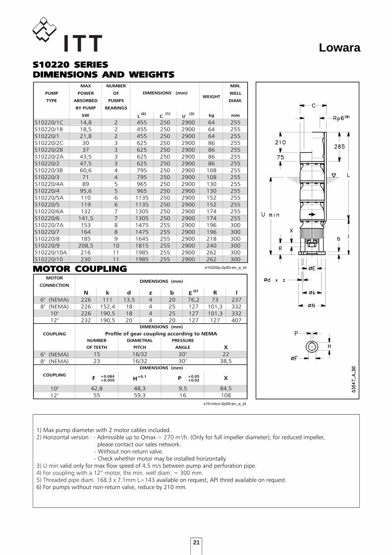
LowaraS10220 SERIESS10220 SERIESS10220 SERIESS10220 SERIESS10220 SERIESDIMENSIONS AND WEIGHTSDIMENSIONS AND WEIGHTSDIMENSIONS AND WEIGHTSDIMENSIONS AND WEIGHTSDIMENSIONS AND WEIGHTSDIMENSIONI E PESI SERIE S10220 A 2 Poli 50 Hz
MAX NUMBER MIN.
PUMP POWER OF WELL
TYPE ABSORBED PUMPS DIAM.
BY PUMP BEARINGS
kW L(6)
C (1)
U (3) kg mm
S10220/1C 14,8 2 455 250 2900 64 255
S10220/1B 18,5 2 455 250 2900 64 255
S10220/1 21,8 2 455 250 2900 64 255
S10220/2C 30 3 625 250 2900 86 255
S10220/2B 37 3 625 250 2900 86 255
S10220/2A 43,5 3 625 250 2900 86 255
S10220/2 47,5 3 625 250 2900 86 255
S10220/3B 60,6 4 795 250 2900 108 255
S10220/3 71 4 795 250 2900 108 255
S10220/4A 89 5 965 250 2900 130 255
S10220/4 95,6 5 965 250 2900 130 255
S10220/5A 110 6 1135 250 2900 152 255
S10220/5 119 6 1135 250 2900 152 255
S10220/6A 132 7 1305 250 2900 174 255
S10220/6 141,5 7 1305 250 2900 174 255
S10220/7A 153 8 1475 255 2900 196 300
S10220/7 164 8 1475 255 2900 196 300
S10220/8 185 9 1645 255 2900 218 300
S10220/9 208,5 10 1815 255 2900 240 300
S10220/10A 216 11 1985 255 2900 262 300
S10220/10 230 11 1985 255 2900 262 300
s10220p-2p50-en_a_td
DIMENSIONS (mm)WEIGHT
1) Max pump diameter with 2 motor cables included.2) Horizontal version : - Admissible up to Qmax = 270 m3/h. (Only for full impeller diameter); for reduced impeller, please contact our sales network. - Without non-return valve. - Check whether motor may be installed horizontally.3) U min valid only for max flow speed of 4,5 m/s between pump and perforation pipe.4) For coupling with a 12” motor, the min. well diam. = 300 mm.5) Threaded pipe diam. 168.3 x 7.1mm L=143 available on request, API thred available on request.6) For pumps without non-return valve, reduce by 210 mm.
DIMENSIONI ACCOPPIAMENTO MOTORI SERIE S10 2 Poli 50 H
MOTOR
CONNECTION
N k d z b EH7 R l
6" (NEMA) 226 111 13,5 4 20 76,2 73 237
8" (NEMA) 226 152,4 18 4 25 127 101,3 332
10" 226 190,5 18 4 25 127 101,3 332
12" 232 190,5 20 4 20 127 127 407
COUPLING
6" (NEMA)
8" (NEMA)
COUPLING +0.084 +0.05+0.059 +0.02
10"
12"
s10-mtcn-2p50-en_a_td
DIMENSIONS (mm)
NUMBER
OF TEETH
DIMENSIONS (mm)
Profile of gear coupling according to NEMA
DIAMETRAL
PITCH
PRESSURE
ANGLE
9,5
16
84,5
108
42,8
55
H+0.1
48,3
59,3
DIMENSIONS (mm)
F P X
X
15
23
16/32
16/32
30°
30°
22
38,5
MOTOR COUPLINGMOTOR COUPLINGMOTOR COUPLINGMOTOR COUPLINGMOTOR COUPLING
22
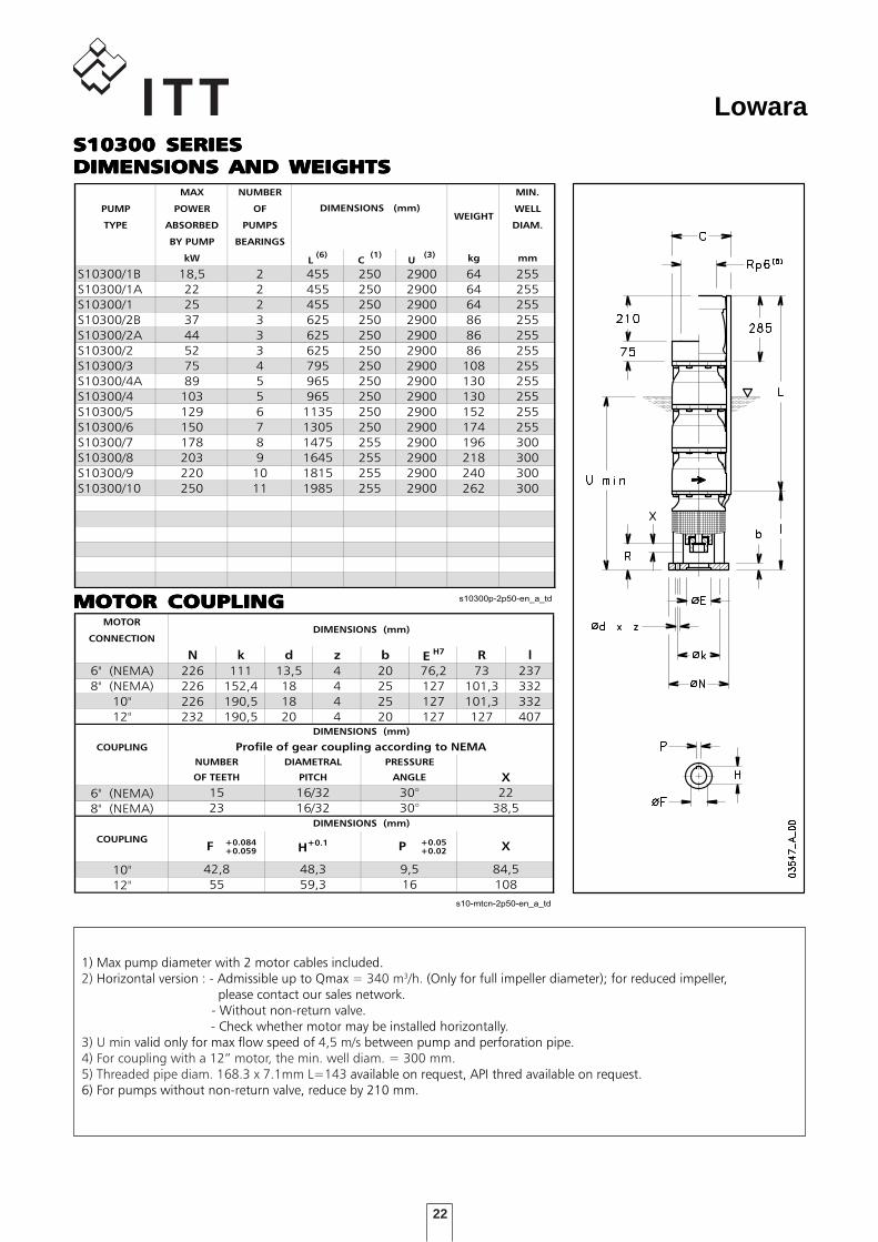
LowaraS10300 SERIESS10300 SERIESS10300 SERIESS10300 SERIESS10300 SERIESDIMENSIONS AND WEIGHTSDIMENSIONS AND WEIGHTSDIMENSIONS AND WEIGHTSDIMENSIONS AND WEIGHTSDIMENSIONS AND WEIGHTSDIMENSIONI E PESI SERIE S10300 A 2 Poli 50 Hz
MAX NUMBER MIN.
PUMP POWER OF WELL
TYPE ABSORBED PUMPS DIAM.
BY PUMP BEARINGS
kW L(6)
C (1)
U (3) kg mm
S10300/1B 18,5 2 455 250 2900 64 255
S10300/1A 22 2 455 250 2900 64 255
S10300/1 25 2 455 250 2900 64 255
S10300/2B 37 3 625 250 2900 86 255
S10300/2A 44 3 625 250 2900 86 255
S10300/2 52 3 625 250 2900 86 255
S10300/3 75 4 795 250 2900 108 255
S10300/4A 89 5 965 250 2900 130 255
S10300/4 103 5 965 250 2900 130 255
S10300/5 129 6 1135 250 2900 152 255
S10300/6 150 7 1305 250 2900 174 255
S10300/7 178 8 1475 255 2900 196 300
S10300/8 203 9 1645 255 2900 218 300
S10300/9 220 10 1815 255 2900 240 300
S10300/10 250 11 1985 255 2900 262 300
s10300p-2p50-en_a_td
DIMENSIONS (mm)WEIGHT
1) Max pump diameter with 2 motor cables included.2) Horizontal version : - Admissible up to Qmax = 340 m3/h. (Only for full impeller diameter); for reduced impeller, please contact our sales network. - Without non-return valve. - Check whether motor may be installed horizontally.3) U min valid only for max flow speed of 4,5 m/s between pump and perforation pipe.4) For coupling with a 12” motor, the min. well diam. = 300 mm.5) Threaded pipe diam. 168.3 x 7.1mm L=143 available on request, API thred available on request.6) For pumps without non-return valve, reduce by 210 mm.
DIMENSIONI ACCOPPIAMENTO MOTORI SERIE S10 2 Poli 50 H
MOTOR
CONNECTION
N k d z b EH7 R l
6" (NEMA) 226 111 13,5 4 20 76,2 73 237
8" (NEMA) 226 152,4 18 4 25 127 101,3 332
10" 226 190,5 18 4 25 127 101,3 332
12" 232 190,5 20 4 20 127 127 407
COUPLING
6" (NEMA)
8" (NEMA)
COUPLING +0.084 +0.05+0.059 +0.02
10"
12"
s10-mtcn-2p50-en_a_td
DIMENSIONS (mm)
NUMBER
OF TEETH
DIMENSIONS (mm)
Profile of gear coupling according to NEMA
DIAMETRAL
PITCH
PRESSURE
ANGLE
9,5
16
84,5
108
42,8
55
H+0.1
48,3
59,3
DIMENSIONS (mm)
F P X
X
15
23
16/32
16/32
30°
30°
22
38,5
MOTOR COUPLINGMOTOR COUPLINGMOTOR COUPLINGMOTOR COUPLINGMOTOR COUPLING
23
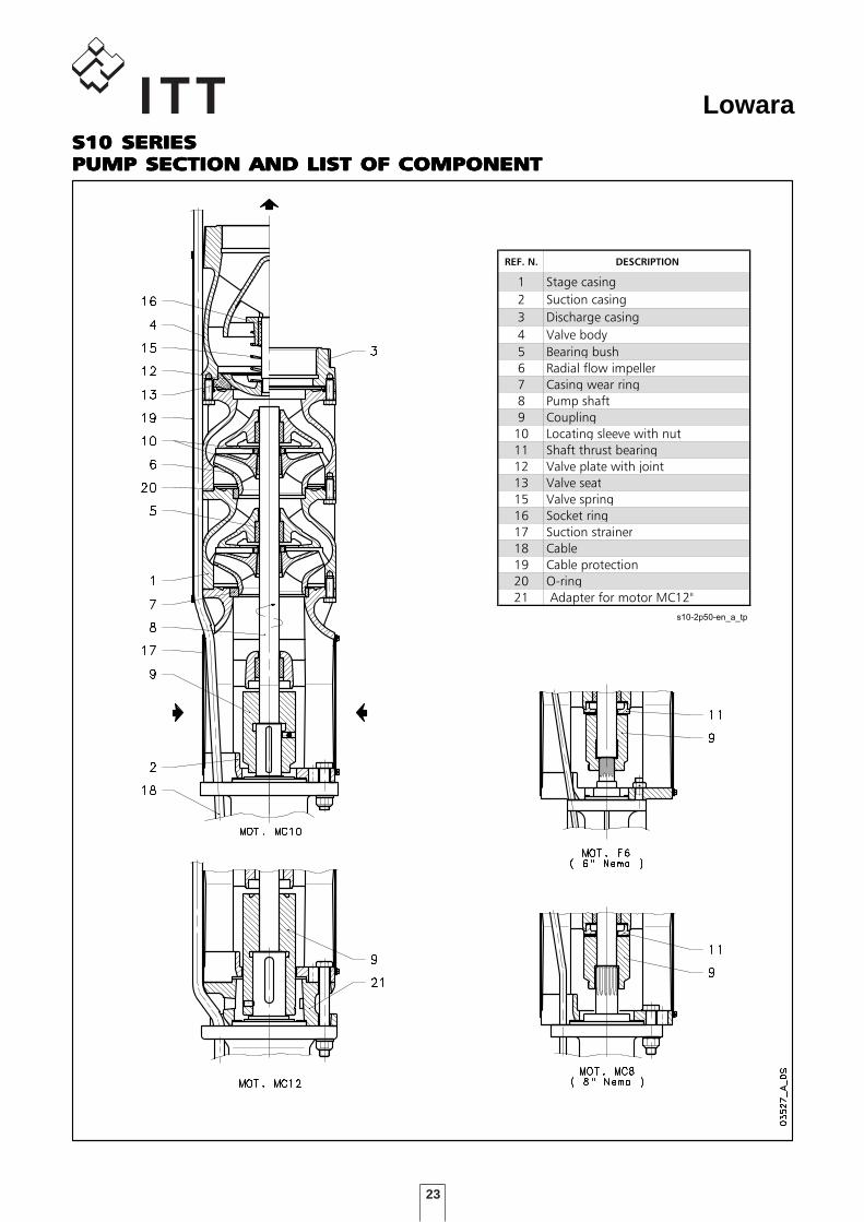
LowaraS10 SERIESS10 SERIESS10 SERIESS10 SERIESS10 SERIESPUMP SECTION AND LIST OF COMPONENTPUMP SECTION AND LIST OF COMPONENTPUMP SECTION AND LIST OF COMPONENTPUMP SECTION AND LIST OF COMPONENTPUMP SECTION AND LIST OF COMPONENT
DENOMINAZIONE COMPONENTI
SERIE S10-2poli 50 Hz
REF. N. DESCRIPTION
1 Stage casing
2 Suction casing
3 Discharge casing
4 Valve body
5 Bearing bush
6 Radial flow impeller
7 Casing wear ring
8 Pump shaft
9 Coupling
10 Locating sleeve with nut
11 Shaft thrust bearing
12 Valve plate with joint
13 Valve seat
15 Valve spring
16 Socket ring
17 Suction strainer
18 Cable
19 Cable protection
20 O-ring
21 Adapter for motor MC12"
s10-2p50-en_a_tp
24
Lowara
25
Lowara
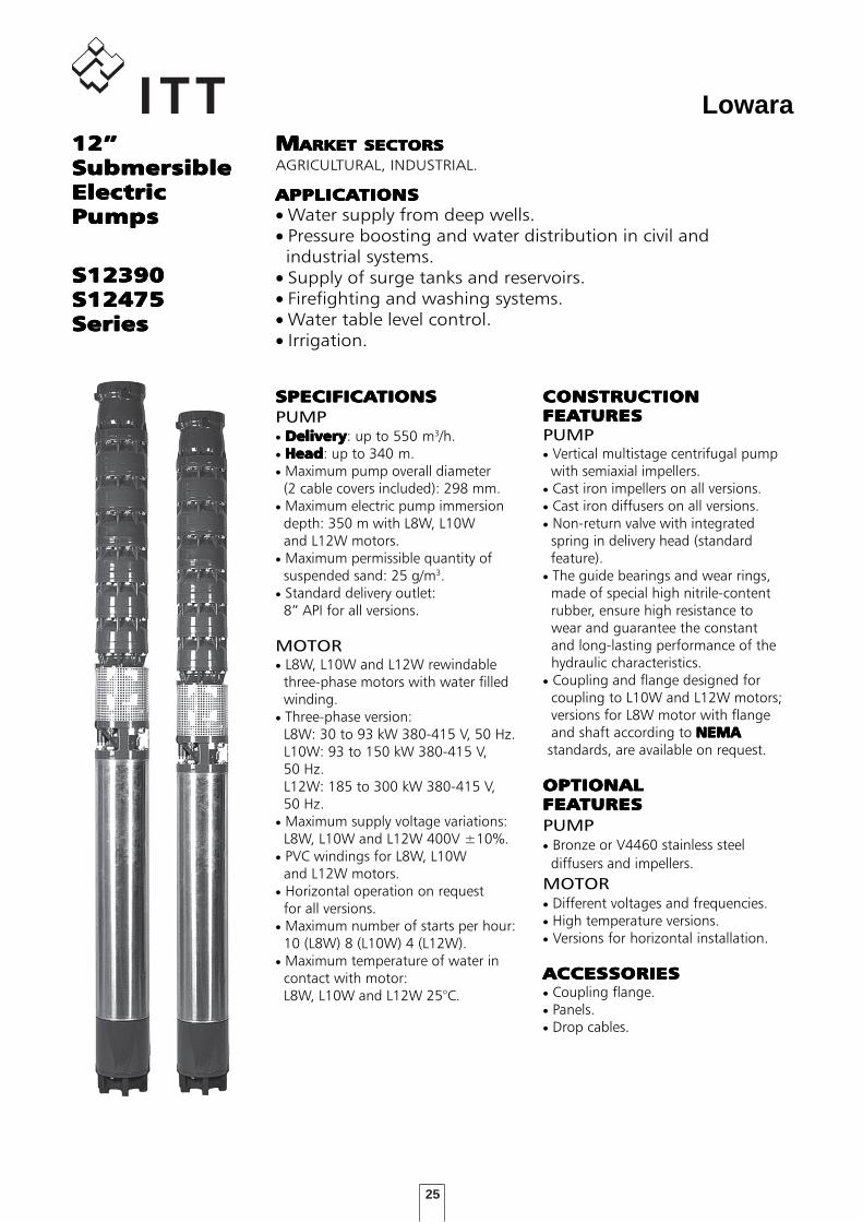
APPLICAAPPLICAAPPLICAAPPLICAAPPLICATIONSTIONSTIONSTIONSTIONS• Water supply from deep wells.• Pressure boosting and water distribution in civil and industrial systems.• Supply of surge tanks and reservoirs.• Firefighting and washing systems.• Water table level control.• Irrigation.
12”12”12”12”12”SubmersibleSubmersibleSubmersibleSubmersibleSubmersibleElectricElectricElectricElectricElectricPumpsPumpsPumpsPumpsPumps
MMMMMARKET SECTORSARKET SECTORSARKET SECTORSARKET SECTORSARKET SECTORSAGRICULTURAL, INDUSTRIAL.
S12390S12390S12390S12390S12390S12475S12475S12475S12475S12475SeriesSeriesSeriesSeriesSeries
SPECIFICASPECIFICASPECIFICASPECIFICASPECIFICATIONSTIONSTIONSTIONSTIONSPUMP• DeliveryDeliveryDeliveryDeliveryDelivery: up to 550 m3/h.• HeadHeadHeadHeadHead: up to 340 m.• Maximum pump overall diameter (2 cable covers included): 298 mm.• Maximum electric pump immersion depth: 350 m with L8W, L10W and L12W motors.• Maximum permissible quantity of suspended sand: 25 g/m3.• Standard delivery outlet: 8” API for all versions.
MOTOR• L8W, L10W and L12W rewindable three-phase motors with water filled winding.• Three-phase version: L8W: 30 to 93 kW 380-415 V, 50 Hz. L10W: 93 to 150 kW 380-415 V, 50 Hz. L12W: 185 to 300 kW 380-415 V, 50 Hz.• Maximum supply voltage variations: L8W, L10W and L12W 400V ±10%.• PVC windings for L8W, L10W and L12W motors.• Horizontal operation on request for all versions.• Maximum number of starts per hour: 10 (L8W) 8 (L10W) 4 (L12W).• Maximum temperature of water in contact with motor: L8W, L10W and L12W 25°C.
CONSTRUCTIONCONSTRUCTIONCONSTRUCTIONCONSTRUCTIONCONSTRUCTIONFEAFEAFEAFEAFEATURESTURESTURESTURESTURESPUMP• Vertical multistage centrifugal pump with semiaxial impellers.• Cast iron impellers on all versions.• Cast iron diffusers on all versions.• Non-return valve with integrated spring in delivery head (standard feature).• The guide bearings and wear rings, made of special high nitrile-content rubber, ensure high resistance to wear and guarantee the constant and long-lasting performance of the hydraulic characteristics.• Coupling and flange designed for coupling to L10W and L12W motors; versions for L8W motor with flange and shaft according to NEMANEMANEMANEMANEMA standards, are available on request.
OPTIONALOPTIONALOPTIONALOPTIONALOPTIONALFEAFEAFEAFEAFEATURESTURESTURESTURESTURESPUMP• Bronze or V4460 stainless steel diffusers and impellers.MOTOR• Different voltages and frequencies.• High temperature versions.• Versions for horizontal installation.
ACCESACCESACCESACCESACCESSORIESSORIESSORIESSORIESSORIES• Coupling flange.• Panels.• Drop cables.
26
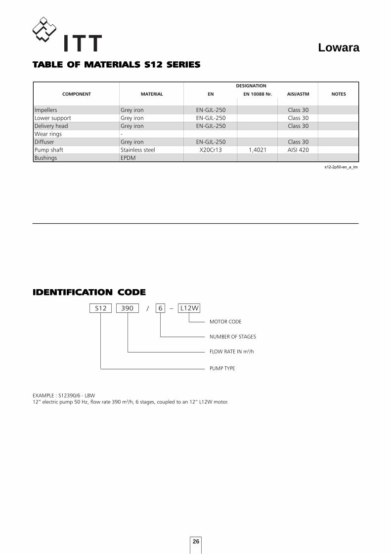
LowaraTTTTTABLE OF MAABLE OF MAABLE OF MAABLE OF MAABLE OF MATERIALS S12 SERIESTERIALS S12 SERIESTERIALS S12 SERIESTERIALS S12 SERIESTERIALS S12 SERIESTABELLA MATERIALI S12
COMPONENT MATERIAL EN EN 10088 Nr. AISI/ASTM NOTES
Impellers Grey iron EN-GJL-250 Class 30
Lower support Grey iron EN-GJL-250 Class 30
Delivery head Grey iron EN-GJL-250 Class 30
Wear rings -
Diffuser Grey iron EN-GJL-250 Class 30
Pump shaft Stainless steel X20Cr13 1,4021 AISI 420
Bushings EPDM
s12-2p50-en_a_tm
DESIGNATION
L12WS12 /
NUMBER OF STAGES
FLOW RATE IN m3/h
MOTOR CODE
390 6
PUMP TYPE
EXAMPLE : S12390/6 - L8W12” electric pump 50 Hz, flow rate 390 m3/h, 6 stages, coupled to an 12” L12W motor.
IDENTIFICAIDENTIFICAIDENTIFICAIDENTIFICAIDENTIFICATION CODETION CODETION CODETION CODETION CODE
27
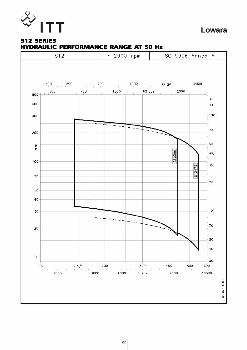
LowaraS12 SERIESS12 SERIESS12 SERIESS12 SERIESS12 SERIESHYDRAHYDRAHYDRAHYDRAHYDRAULIC PERFORMANCE RANGE AULIC PERFORMANCE RANGE AULIC PERFORMANCE RANGE AULIC PERFORMANCE RANGE AULIC PERFORMANCE RANGE AT 50 HzT 50 HzT 50 HzT 50 HzT 50 Hz
28
Lowara
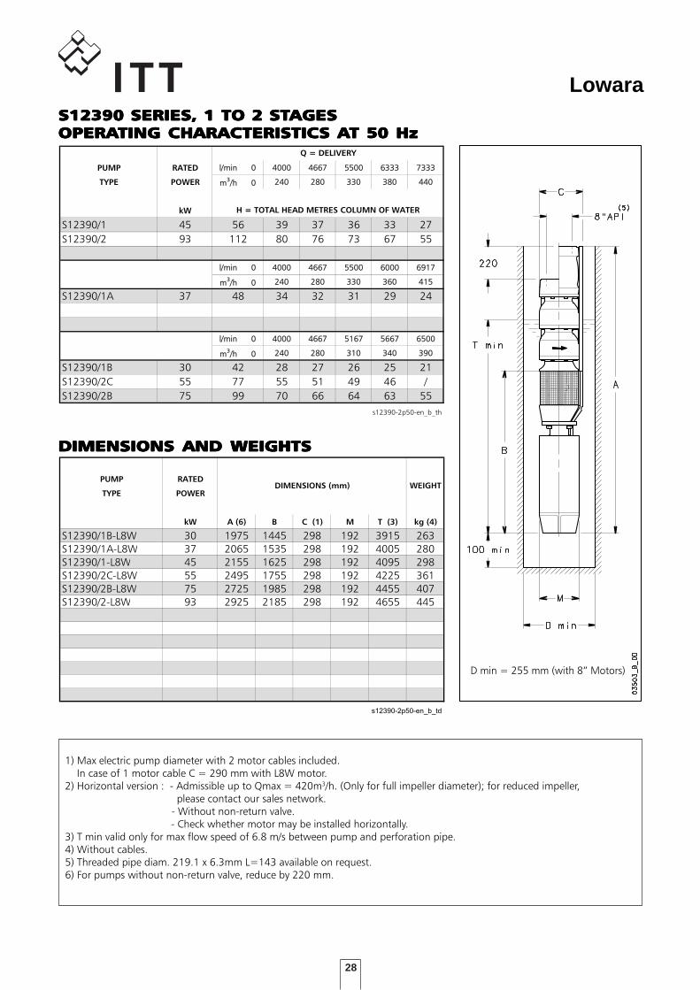
DIMENSIONS AND WEIGHTSDIMENSIONS AND WEIGHTSDIMENSIONS AND WEIGHTSDIMENSIONS AND WEIGHTSDIMENSIONS AND WEIGHTS
TABELLA DI PRESTAZIONI IDRAULICHE SERIE S12390 2 poli 50 Hz
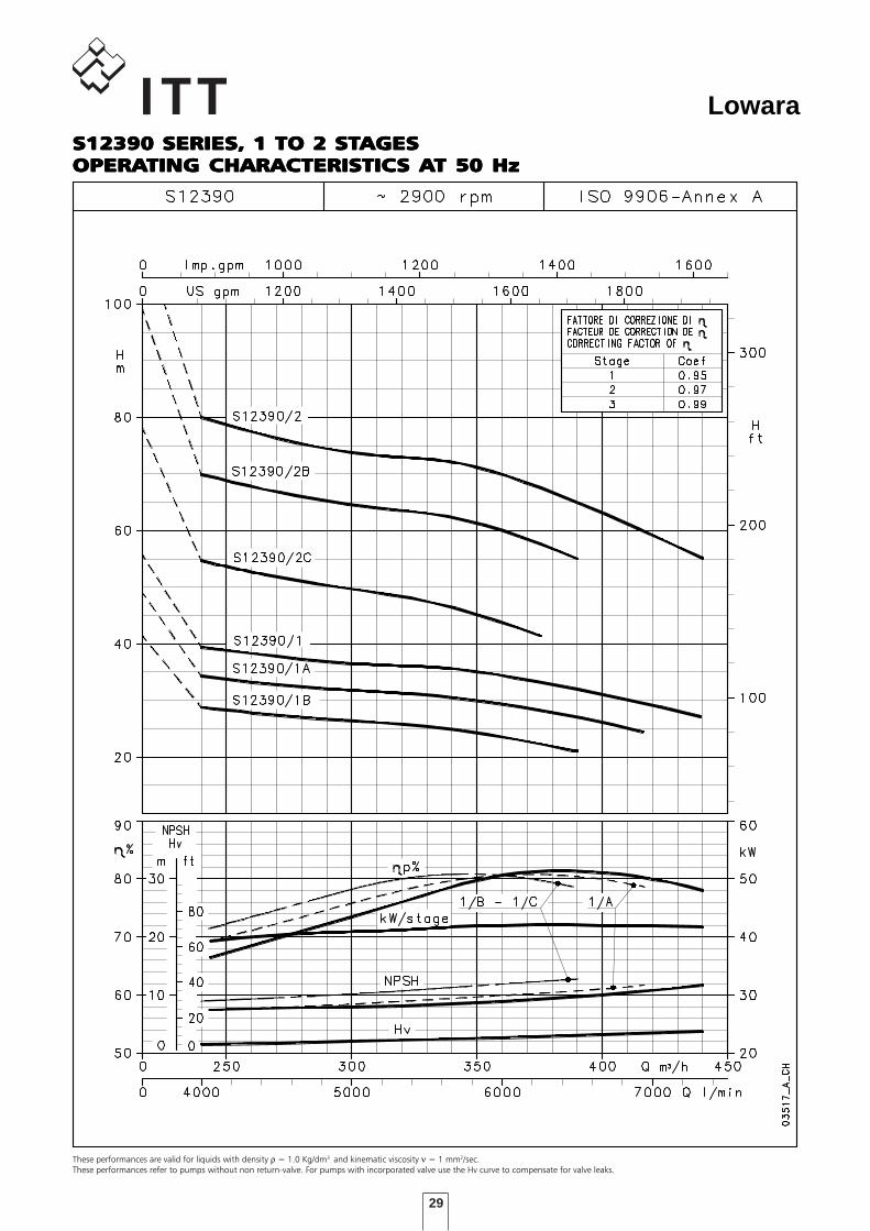
PUMP RATED l/min 0 4000 4667 5500 6333 7333
TYPE POWER m3/h 0 240 280 330 380 440
kW
S12390/1 45 56 39 37 36 33 27
S12390/2 93 112 80 76 73 67 55
l/min 0 4000 4667 5500 6000 6917
m3/h 0 240 280 330 360 415
S12390/1A 37 48 34 32 31 29 24
l/min 0 4000 4667 5167 5667 6500
m3/h 0 240 280 310 340 390
S12390/1B 30 42 28 27 26 25 21
S12390/2C 55 77 55 51 49 46 /
S12390/2B 75 99 70 66 64 63 55
s12390-2p50-en_b_th
H = TOTAL HEAD METRES COLUMN OF WATER
Q = DELIVERY
DIMENSIONI E PESI SERIE S12390 2 poli 50 Hz
PUMP RATED
TYPE POWER
kW A (6) B C (1) M T (3) kg (4)
S12390/1B-L8W 30 1975 1445 298 192 3915 263
S12390/1A-L8W 37 2065 1535 298 192 4005 280
S12390/1-L8W 45 2155 1625 298 192 4095 298
S12390/2C-L8W 55 2495 1755 298 192 4225 361
S12390/2B-L8W 75 2725 1985 298 192 4455 407
S12390/2-L8W 93 2925 2185 298 192 4655 445
s12390-2p50-en_b_td
WEIGHTDIMENSIONS (mm)
1) Max electric pump diameter with 2 motor cables included. In case of 1 motor cable C = 290 mm with L8W motor.2) Horizontal version : - Admissible up to Qmax = 420m3/h. (Only for full impeller diameter); for reduced impeller, please contact our sales network. - Without non-return valve. - Check whether motor may be installed horizontally.3) T min valid only for max flow speed of 6.8 m/s between pump and perforation pipe.4) Without cables.5) Threaded pipe diam. 219.1 x 6.3mm L=143 available on request.6) For pumps without non-return valve, reduce by 220 mm.
D min = 255 mm (with 8” Motors)
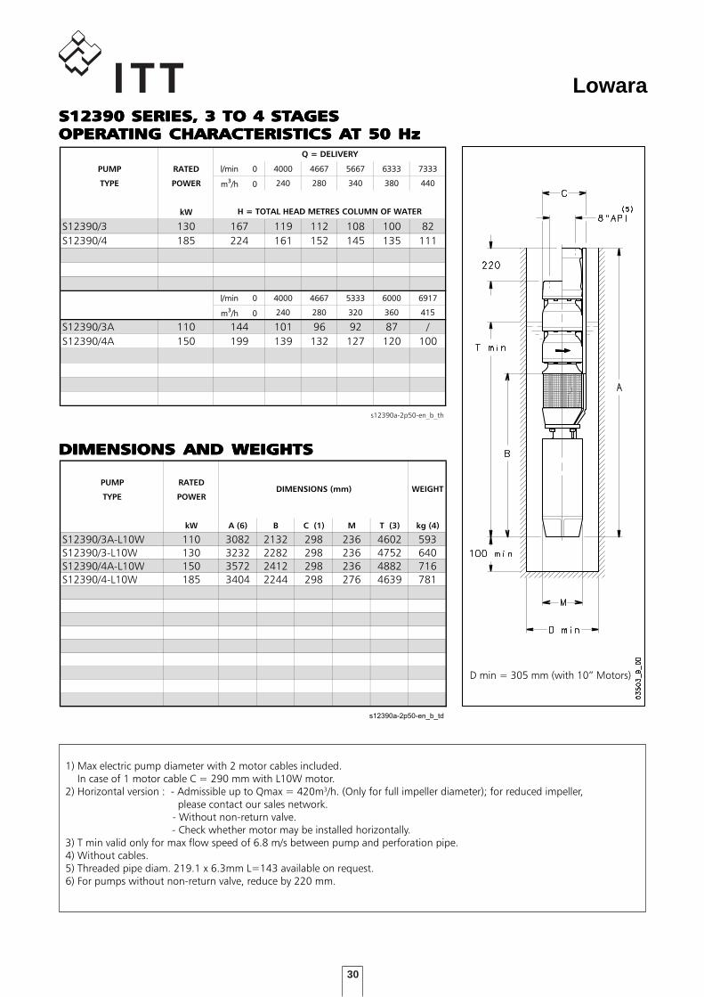
S12390 SERIES, 1 TO 2 STS12390 SERIES, 1 TO 2 STS12390 SERIES, 1 TO 2 STS12390 SERIES, 1 TO 2 STS12390 SERIES, 1 TO 2 STAGESAGESAGESAGESAGESOPERAOPERAOPERAOPERAOPERATING CHARACTERISTICTING CHARACTERISTICTING CHARACTERISTICTING CHARACTERISTICTING CHARACTERISTICS AS AS AS AS AT 50 HzT 50 HzT 50 HzT 50 HzT 50 Hz
29
Lowara
These performances are valid for liquids with density ρ = 1.0 Kg/dm3 and kinematic viscosity ν = 1 mm2/sec.These performances refer to pumps without non return-valve. For pumps with incorporated valve use the Hv curve to compensate for valve leaks.
S12390 SERIES, 1 TO 2 STS12390 SERIES, 1 TO 2 STS12390 SERIES, 1 TO 2 STS12390 SERIES, 1 TO 2 STS12390 SERIES, 1 TO 2 STAGESAGESAGESAGESAGESOPERAOPERAOPERAOPERAOPERATING CHARACTERISTICTING CHARACTERISTICTING CHARACTERISTICTING CHARACTERISTICTING CHARACTERISTICS AS AS AS AS AT 50 HzT 50 HzT 50 HzT 50 HzT 50 Hz
30
Lowara
DIMENSIONS AND WEIGHTSDIMENSIONS AND WEIGHTSDIMENSIONS AND WEIGHTSDIMENSIONS AND WEIGHTSDIMENSIONS AND WEIGHTS
TABELLA DI PRESTAZIONI IDRAULICHE SERIE S12390 2 poli 50 Hz
PUMP RATED l/min 0l/min 0 40004000 46674667 56675667 63336333 73337333
TYPE POWER m3/h 0/h 0 240240 280280 340340 380380 440440
kW
S12390/3 130 167 119 112 108 100 82
S12390/4 185 224 161 152 145 135 111
l/min 0l/min 0 40004000 46674667 53335333 60006000 69176917
m3/h 0/h 0 240240 280280 320320 360360 415415
S12390/3A 110 144 101 96 92 87 /
S12390/4A 150 199 139 132 127 120 100
s12390a-2p50-en_b_th
H = TOTAL HEAD METRES COLUMN OF WATER
Q = DELIVERY
DIMENSIONI E PESI SERIE S12390 2 poli 50 Hz
PUMP RATED
TYPE POWER
kW A (6) B C (1) M T (3) kg (4)
S12390/3A-L10W 110 3082 2132 298 236 4602 593
S12390/3-L10W 130 3232 2282 298 236 4752 640
S12390/4A-L10W 150 3572 2412 298 236 4882 716
S12390/4-L10W 185 3404 2244 298 276 4639 781
s12390a-2p50-en_b_td
WEIGHTDIMENSIONS (mm)
1) Max electric pump diameter with 2 motor cables included. In case of 1 motor cable C = 290 mm with L10W motor.2) Horizontal version : - Admissible up to Qmax = 420m3/h. (Only for full impeller diameter); for reduced impeller, please contact our sales network. - Without non-return valve. - Check whether motor may be installed horizontally.3) T min valid only for max flow speed of 6.8 m/s between pump and perforation pipe.4) Without cables.5) Threaded pipe diam. 219.1 x 6.3mm L=143 available on request.6) For pumps without non-return valve, reduce by 220 mm.
D min = 305 mm (with 10” Motors)
S12390 SERIES, 3 TO 4 STS12390 SERIES, 3 TO 4 STS12390 SERIES, 3 TO 4 STS12390 SERIES, 3 TO 4 STS12390 SERIES, 3 TO 4 STAGESAGESAGESAGESAGESOPERAOPERAOPERAOPERAOPERATING CHARACTERISTICTING CHARACTERISTICTING CHARACTERISTICTING CHARACTERISTICTING CHARACTERISTICS AS AS AS AS AT 50 HzT 50 HzT 50 HzT 50 HzT 50 Hz
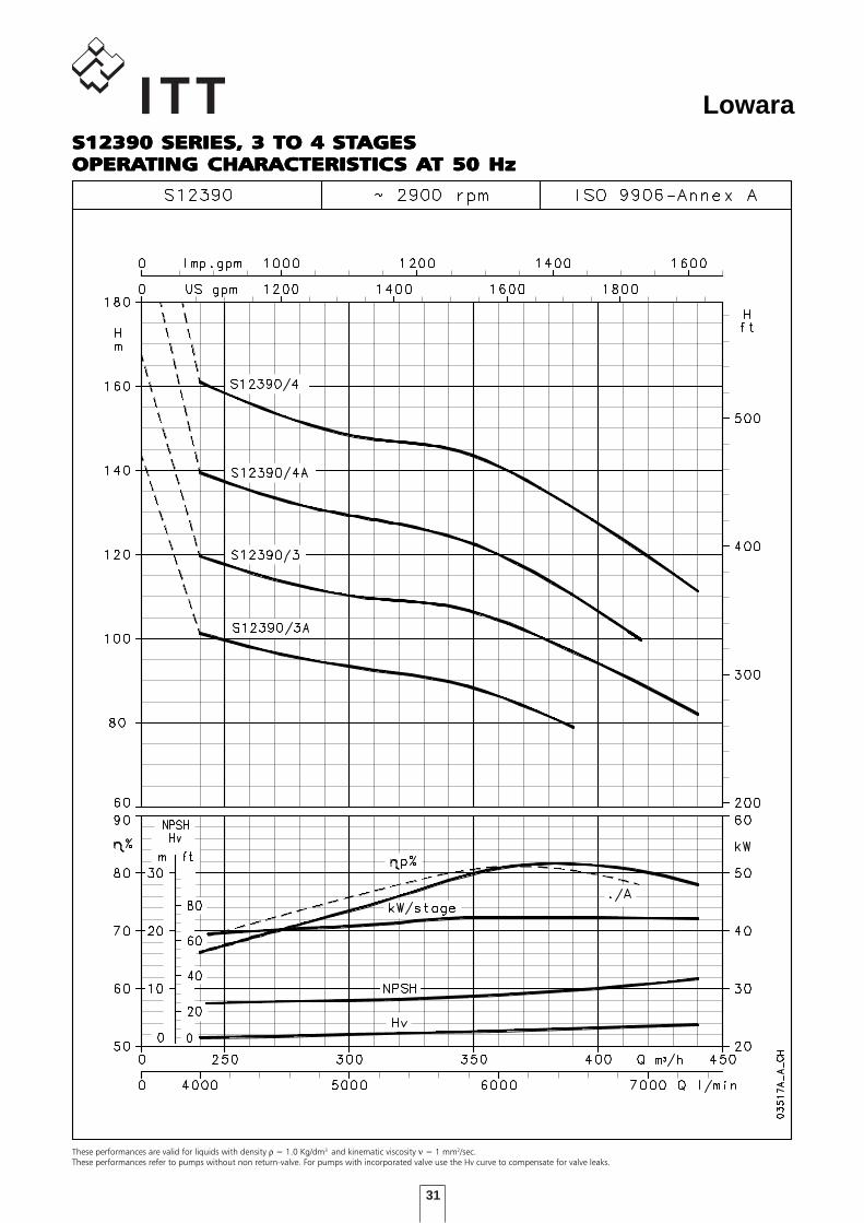
31
Lowara
These performances are valid for liquids with density ρ = 1.0 Kg/dm3 and kinematic viscosity ν = 1 mm2/sec.These performances refer to pumps without non return-valve. For pumps with incorporated valve use the Hv curve to compensate for valve leaks.
S12390 SERIES, 3 TO 4 STS12390 SERIES, 3 TO 4 STS12390 SERIES, 3 TO 4 STS12390 SERIES, 3 TO 4 STS12390 SERIES, 3 TO 4 STAGESAGESAGESAGESAGESOPERAOPERAOPERAOPERAOPERATING CHARACTERISTICTING CHARACTERISTICTING CHARACTERISTICTING CHARACTERISTICTING CHARACTERISTICS AS AS AS AS AT 50 HzT 50 HzT 50 HzT 50 HzT 50 Hz
32
Lowara
DIMENSIONS AND WEIGHTSDIMENSIONS AND WEIGHTSDIMENSIONS AND WEIGHTSDIMENSIONS AND WEIGHTSDIMENSIONS AND WEIGHTS
TABELLA DI PRESTAZIONI IDRAULICHE SERIE S12390 2 poli 50 Hz
PUMP RATED l/min 0l/min 0 40004000 46674667 56675667 63336333 73337333
TYPE POWER m3/h 0/h 0 240240 280280 340340 380380 440440
kW
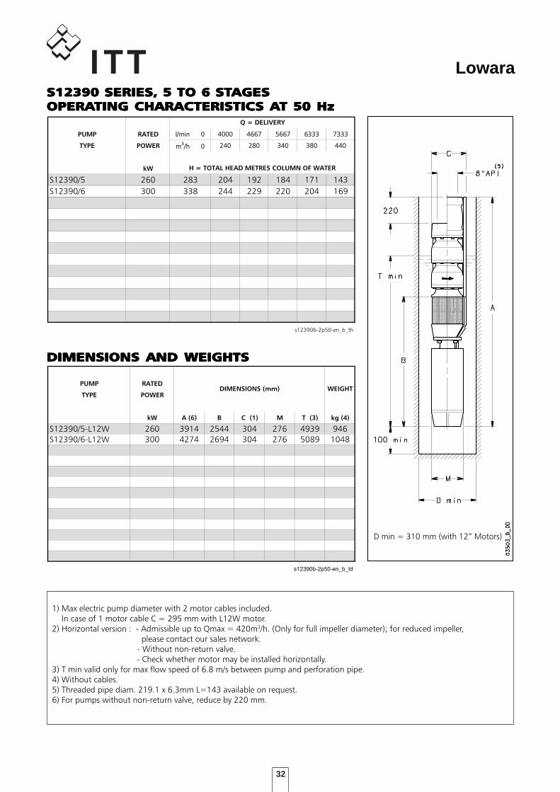
S12390/5 260 283 204 192 184 171 143
S12390/6 300 338 244 229 220 204 169
s12390b-2p50-en_b_th
H = TOTAL HEAD METRES COLUMN OF WATER
Q = DELIVERY
DIMENSIONI E PESI SERIE S12390 2 poli 50 Hz
PUMP RATED
TYPE POWER
kW A (6) B C (1) M T (3) kg (4)
S12390/5-L12W 260 3914 2544 304 276 4939 946
S12390/6-L12W 300 4274 2694 304 276 5089 1048
s12390b-2p50-en_b_td
WEIGHTDIMENSIONS (mm)
1) Max electric pump diameter with 2 motor cables included. In case of 1 motor cable C = 295 mm with L12W motor.2) Horizontal version : - Admissible up to Qmax = 420m3/h. (Only for full impeller diameter); for reduced impeller, please contact our sales network. - Without non-return valve. - Check whether motor may be installed horizontally.3) T min valid only for max flow speed of 6.8 m/s between pump and perforation pipe.4) Without cables.5) Threaded pipe diam. 219.1 x 6.3mm L=143 available on request.6) For pumps without non-return valve, reduce by 220 mm.
D min = 310 mm (with 12” Motors)
S12390 SERIES, 5 TO 6 STS12390 SERIES, 5 TO 6 STS12390 SERIES, 5 TO 6 STS12390 SERIES, 5 TO 6 STS12390 SERIES, 5 TO 6 STAGESAGESAGESAGESAGESOPERAOPERAOPERAOPERAOPERATING CHARACTERISTICTING CHARACTERISTICTING CHARACTERISTICTING CHARACTERISTICTING CHARACTERISTICS AS AS AS AS AT 50 HzT 50 HzT 50 HzT 50 HzT 50 Hz
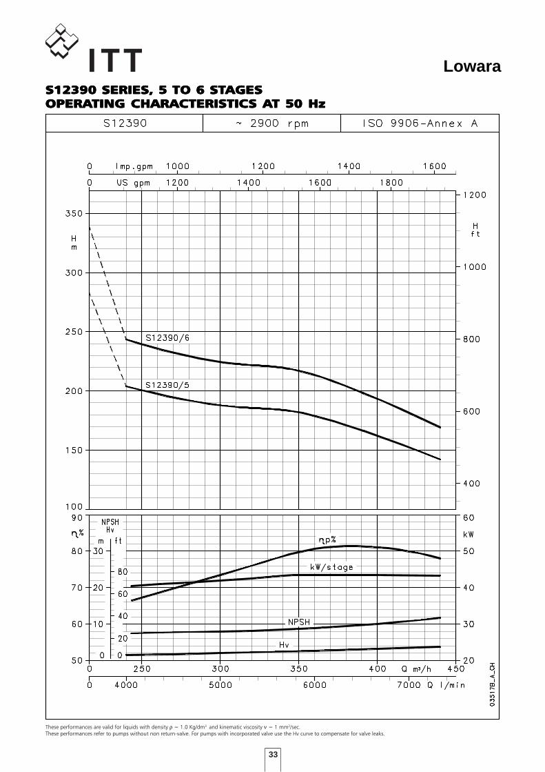
33
Lowara
These performances are valid for liquids with density ρ = 1.0 Kg/dm3 and kinematic viscosity ν = 1 mm2/sec.These performances refer to pumps without non return-valve. For pumps with incorporated valve use the Hv curve to compensate for valve leaks.
S12390 SERIES, 5 TO 6 STS12390 SERIES, 5 TO 6 STS12390 SERIES, 5 TO 6 STS12390 SERIES, 5 TO 6 STS12390 SERIES, 5 TO 6 STAGESAGESAGESAGESAGESOPERAOPERAOPERAOPERAOPERATING CHARACTERISTICTING CHARACTERISTICTING CHARACTERISTICTING CHARACTERISTICTING CHARACTERISTICS AS AS AS AS AT 50 HzT 50 HzT 50 HzT 50 HzT 50 Hz
34
Lowara
DIMENSIONS AND WEIGHTSDIMENSIONS AND WEIGHTSDIMENSIONS AND WEIGHTSDIMENSIONS AND WEIGHTSDIMENSIONS AND WEIGHTS
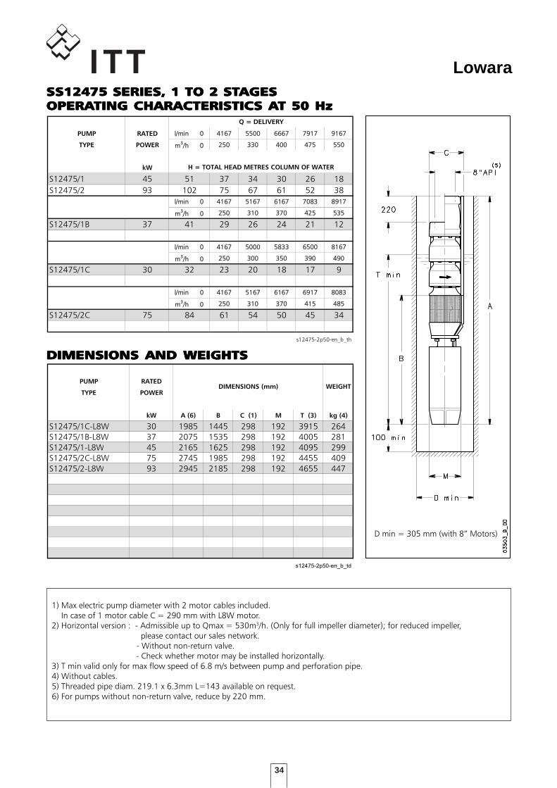
TABELLA DI PRESTAZIONI IDRAULICHE SERIE S12475 2 poli 50 Hz
PUMP RATED l/min 0 4167 5500 6667 7917 9167
TYPE POWER m3/h 0 250 330 400 475 550
kW
S12475/1 45 51 37 34 30 26 18
S12475/2 93 102 75 67 61 52 38
l/min 0 4167 5167 6167 7083 8917
m3/h 0 250 310 370 425 535
S12475/1B 37 41 29 26 24 21 12
l/min 0 4167 5000 5833 6500 8167
m3/h 0 250 300 350 390 490
S12475/1C 30 32 23 20 18 17 9
l/min 0 4167 5167 6167 6917 8083
m3/h 0 250 310 370 415 485
S12475/2C 75 84 61 54 50 45 34
s12475-2p50-en_b_th
H = TOTAL HEAD METRES COLUMN OF WATER
Q = DELIVERY
DIMENSIONI E PESI SERIE S12475 2 poli 50 Hz
PUMP RATED
TYPE POWER
kW A (6) B C (1) M T (3) kg (4)
S12475/1C-L8W 30 1985 1445 298 192 3915 264
S12475/1B-L8W 37 2075 1535 298 192 4005 281
S12475/1-L8W 45 2165 1625 298 192 4095 299
S12475/2C-L8W 75 2745 1985 298 192 4455 409
S12475/2-L8W 93 2945 2185 298 192 4655 447
s12475-2p50-en_b_td
WEIGHTDIMENSIONS (mm)
1) Max electric pump diameter with 2 motor cables included. In case of 1 motor cable C = 290 mm with L8W motor.2) Horizontal version : - Admissible up to Qmax = 530m3/h. (Only for full impeller diameter); for reduced impeller, please contact our sales network. - Without non-return valve. - Check whether motor may be installed horizontally.3) T min valid only for max flow speed of 6.8 m/s between pump and perforation pipe.4) Without cables.5) Threaded pipe diam. 219.1 x 6.3mm L=143 available on request.6) For pumps without non-return valve, reduce by 220 mm.
D min = 305 mm (with 8” Motors)
SSSSSS12475 SERIES, 1 TO 2 STS12475 SERIES, 1 TO 2 STS12475 SERIES, 1 TO 2 STS12475 SERIES, 1 TO 2 STS12475 SERIES, 1 TO 2 STAGESAGESAGESAGESAGESOPERAOPERAOPERAOPERAOPERATING CHARACTERISTICTING CHARACTERISTICTING CHARACTERISTICTING CHARACTERISTICTING CHARACTERISTICS AS AS AS AS AT 50 HzT 50 HzT 50 HzT 50 HzT 50 Hz
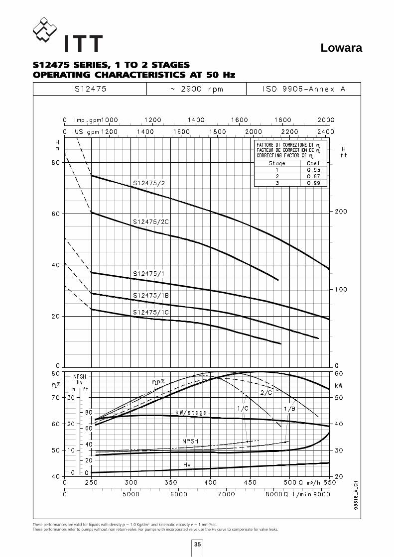
35
Lowara
These performances are valid for liquids with density ρ = 1.0 Kg/dm3 and kinematic viscosity ν = 1 mm2/sec.These performances refer to pumps without non return-valve. For pumps with incorporated valve use the Hv curve to compensate for valve leaks.
S12475 SERIES, 1 TO 2 STS12475 SERIES, 1 TO 2 STS12475 SERIES, 1 TO 2 STS12475 SERIES, 1 TO 2 STS12475 SERIES, 1 TO 2 STAGESAGESAGESAGESAGESOPERAOPERAOPERAOPERAOPERATING CHARACTERISTICTING CHARACTERISTICTING CHARACTERISTICTING CHARACTERISTICTING CHARACTERISTICS AS AS AS AS AT 50 HzT 50 HzT 50 HzT 50 HzT 50 Hz

36
Lowara
DIMENSIONS AND WEIGHTSDIMENSIONS AND WEIGHTSDIMENSIONS AND WEIGHTSDIMENSIONS AND WEIGHTSDIMENSIONS AND WEIGHTS
TABELLA DI PRESTAZIONI IDRAULICHE SERIE S12475 2 poli 50 Hz
PUMP RATED l/min 0 4167 5500 7500 7917 9167
TYPE POWER m3/h 0 250 330 450 475 550
kW
S12475/3A 130 147 107 96 78 72 52
S12475/3 150 154 113 102 83 78 58
S12475/4 185 205 151 137 112 105 78
l/min 0 4167 5500 6167 7083 8917
m3/h 0 250 330 370 425 535
S12475/4B 150 173 124 108 102 92 55
l/min 0 4167 5000 5833 6667 8167
m3/h 0 250 300 350 400 490
S12475/3C 110 118 85 77 71 64 44
s12475a-2p50-en_b_th
H = TOTAL HEAD METRES COLUMN OF WATER
Q = DELIVERY
DIMENSIONI E PESI SERIE S12475 2 poli 50 Hz
PUMP RATED
TYPE POWER
kW A (6) B C (1) M T (3) kg (4)
S12475/3C-L10W 110 3112 2132 298 236 4602 596
S12475/3A-L10W 130 3262 2282 298 236 4752 643
S12475/3-L10W 150 3392 2412 298 236 4882 682
S12475/4B-L10W 150 3612 2412 298 236 4882 720
S12475/4-L12W 185 3444 2244 304 276 4639 785
s12475a-2p50-en_b_td
WEIGHTDIMENSIONS (mm)
1) Max electric pump diameter with 2 motor cables included. In case of 1 motor cable C = 290 mm with L10W motor and C = 295 mm with L12W motor.2) Horizontal version : - Admissible up to Qmax = 530m3/h. (Only for full impeller diameter); for reduced impeller, please contact our sales network. - Without non-return valve. - Check whether motor may be installed horizontally.3) T min valid only for max flow speed of 6.8 m/s between pump and perforation pipe.4) Without cables.5) Threaded pipe diam. 219.1 x 6.3mm L=143 available on request.6) For pumps without non-return valve, reduce by 220 mm.
D min = 305 mm (with 10” Motors)D min = 310 mm (with 12” Motors)
S12475 SERIES, 3 TO 4 STS12475 SERIES, 3 TO 4 STS12475 SERIES, 3 TO 4 STS12475 SERIES, 3 TO 4 STS12475 SERIES, 3 TO 4 STAGESAGESAGESAGESAGESOPERAOPERAOPERAOPERAOPERATING CHARACTERISTICTING CHARACTERISTICTING CHARACTERISTICTING CHARACTERISTICTING CHARACTERISTICS AS AS AS AS AT 50 HzT 50 HzT 50 HzT 50 HzT 50 Hz
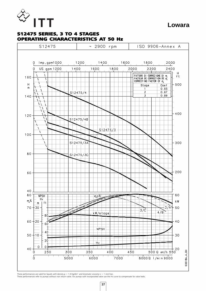
37
Lowara
These performances are valid for liquids with density ρ = 1.0 Kg/dm3 and kinematic viscosity ν = 1 mm2/sec.These performances refer to pumps without non return-valve. For pumps with incorporated valve use the Hv curve to compensate for valve leaks.
S12475 SERIES, 3 TO 4 STS12475 SERIES, 3 TO 4 STS12475 SERIES, 3 TO 4 STS12475 SERIES, 3 TO 4 STS12475 SERIES, 3 TO 4 STAGESAGESAGESAGESAGESOPERAOPERAOPERAOPERAOPERATING CHARACTERISTICTING CHARACTERISTICTING CHARACTERISTICTING CHARACTERISTICTING CHARACTERISTICS AS AS AS AS AT 50 HzT 50 HzT 50 HzT 50 HzT 50 Hz

38
Lowara
DIMENSIONS AND WEIGHTSDIMENSIONS AND WEIGHTSDIMENSIONS AND WEIGHTSDIMENSIONS AND WEIGHTSDIMENSIONS AND WEIGHTS
TABELLA DI PRESTAZIONI IDRAULICHE SERIE S12475 2 poli 50 Hz
PUMP RATED l/min 0l/min 0 4167 5500 6667 7917 9167
TYPE POWER m3/h 0 250 330 400 475 550
kW
S12475/5 260 260 190 173 157 134 100
S12475/6 300 312 230 208 188 160 120
l/min 0l/min 0 4167 5500 6667 7500 9167
m3/h 0 250 330 400 450 550
S12475/5A 220 245 179 161 144 130 86
S12475/6A 300 305 222 201 181 164 113
s12475b-2p50-en_b_th
H = TOTAL HEAD METRES COLUMN OF WATER
Q = DELIVERY
DIMENSIONI E PESI SERIE S12475 2 poli 50 Hz
PUMP RATED
TYPE POWER
kW A (6) B C (1) M T (3) kg (4)
S12475/5A-L12W 220 3814 2394 304 276 4789 887
S12475/5-L12W 260 3964 2544 304 276 4939 951
S12475/6A-L12W 300 4334 2694 304 276 5089 1054
S12475/6-L12W 300 4334 2694 304 276 5089 1054
s12475b-2p50-en_b_td
WEIGHTDIMENSIONS (mm)
1) Max electric pump diameter with 2 motor cables included. In case of 1 motor cable C = 295 mm with L12W motor.2) Horizontal version : - Admissible up to Qmax = 530m3/h. (Only for full impeller diameter); for reduced impeller, please contact our sales network. - Without non-return valve. - Check whether motor may be installed horizontally.3) T min valid only for max flow speed of 6.8 m/s between pump and perforation pipe.4) Without cables.5) Threaded pipe diam. 219.1 x 6.3mm L=143 available on request.6) For pumps without non-return valve, reduce by 220 mm.
D min = 310 mm (with 12” Motors)
S12475 SERIES, 5 TO 6 STS12475 SERIES, 5 TO 6 STS12475 SERIES, 5 TO 6 STS12475 SERIES, 5 TO 6 STS12475 SERIES, 5 TO 6 STAGESAGESAGESAGESAGESOPERAOPERAOPERAOPERAOPERATING CHARACTERISTICTING CHARACTERISTICTING CHARACTERISTICTING CHARACTERISTICTING CHARACTERISTICS AS AS AS AS AT 50 HzT 50 HzT 50 HzT 50 HzT 50 Hz
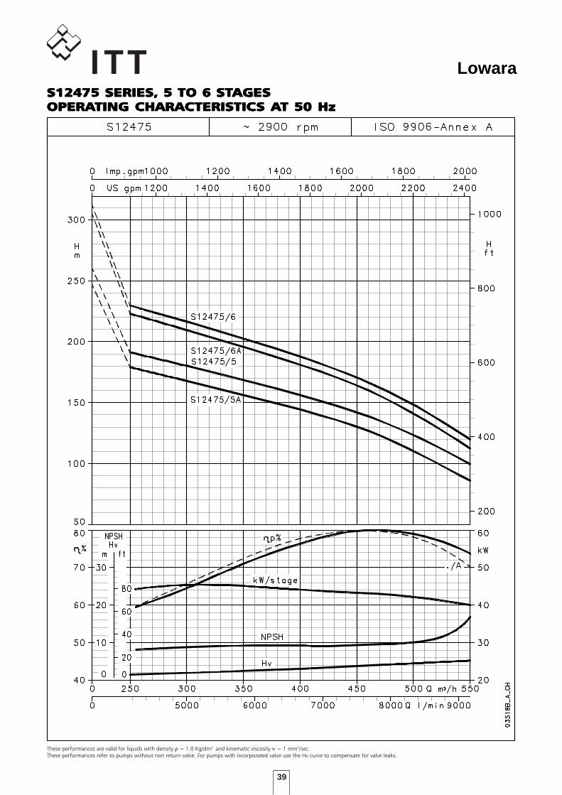
39
Lowara
These performances are valid for liquids with density ρ = 1.0 Kg/dm3 and kinematic viscosity ν = 1 mm2/sec.These performances refer to pumps without non return-valve. For pumps with incorporated valve use the Hv curve to compensate for valve leaks.
S12475 SERIES, 5 TO 6 STS12475 SERIES, 5 TO 6 STS12475 SERIES, 5 TO 6 STS12475 SERIES, 5 TO 6 STS12475 SERIES, 5 TO 6 STAGESAGESAGESAGESAGESOPERAOPERAOPERAOPERAOPERATING CHARACTERISTICTING CHARACTERISTICTING CHARACTERISTICTING CHARACTERISTICTING CHARACTERISTICS AS AS AS AS AT 50 HzT 50 HzT 50 HzT 50 HzT 50 Hz
40
Lowara
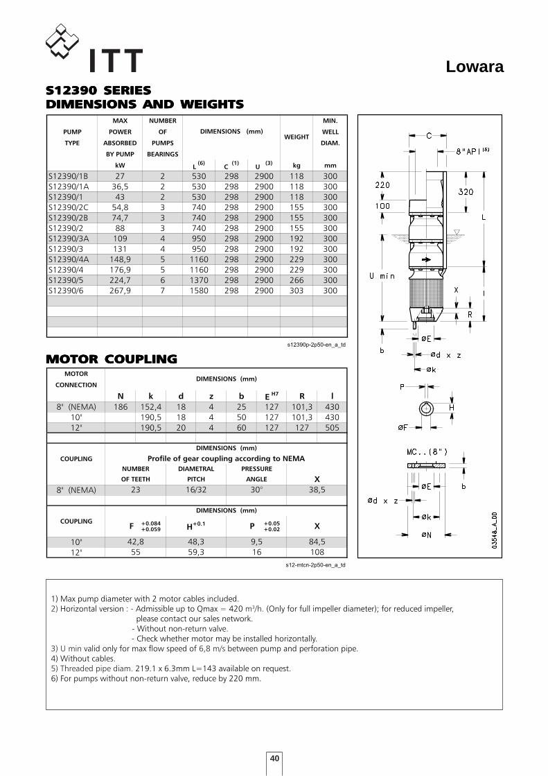
MOTOR COUPLINGMOTOR COUPLINGMOTOR COUPLINGMOTOR COUPLINGMOTOR COUPLING
DIMENSIONI E PESI SERIE S12390 A 2 Poli 50 Hz
MAX NUMBER MIN.
PUMP POWER OF WELL
TYPE ABSORBED PUMPS DIAM.
BY PUMP BEARINGS
kW L(6)
C (1)
U (3) kg mm
S12390/1B 27 2 530 298 2900 118 300
S12390/1A 36,5 2 530 298 2900 118 300
S12390/1 43 2 530 298 2900 118 300
S12390/2C 54,8 3 740 298 2900 155 300
S12390/2B 74,7 3 740 298 2900 155 300
S12390/2 88 3 740 298 2900 155 300
S12390/3A 109 4 950 298 2900 192 300
S12390/3 131 4 950 298 2900 192 300
S12390/4A 148,9 5 1160 298 2900 229 300
S12390/4 176,9 5 1160 298 2900 229 300
S12390/5 224,7 6 1370 298 2900 266 300
S12390/6 267,9 7 1580 298 2900 303 300
s12390p-2p50-en_a_td
DIMENSIONS (mm)WEIGHT
DIMENSIONI ACCOPPIAMENTO MOTORI SERIE S12 2 Poli 50 H
MOTOR
CONNECTION
N k d z b EH7 R l
8" (NEMA) 186 152,4 18 4 25 127 101,3 430
10" 190,5 18 4 50 127 101,3 430
12" 190,5 20 4 60 127 127 505
COUPLING
8" (NEMA)
COUPLING +0.084 +0.05+0.059 +0.02
10"
12"
s12-mtcn-2p50-en_a_td
X
23 16/32 30° 38,5
DIMENSIONS (mm)
F P X
42,8
55
H+0.1
48,3
59,3
9,5
16
84,5
108
DIMENSIONS (mm)
NUMBER
OF TEETH
DIMENSIONS (mm)
Profile of gear coupling according to NEMA
DIAMETRAL
PITCH
PRESSURE
ANGLE
1) Max pump diameter with 2 motor cables included.2) Horizontal version : - Admissible up to Qmax = 420 m3/h. (Only for full impeller diameter); for reduced impeller, please contact our sales network. - Without non-return valve. - Check whether motor may be installed horizontally.3) U min valid only for max flow speed of 6,8 m/s between pump and perforation pipe.4) Without cables.5) Threaded pipe diam. 219.1 x 6.3mm L=143 available on request.6) For pumps without non-return valve, reduce by 220 mm.
S12390 SERIESS12390 SERIESS12390 SERIESS12390 SERIESS12390 SERIESDIMENSIONS AND WEIGHTSDIMENSIONS AND WEIGHTSDIMENSIONS AND WEIGHTSDIMENSIONS AND WEIGHTSDIMENSIONS AND WEIGHTS

41
Lowara
MOTOR COUPLINGMOTOR COUPLINGMOTOR COUPLINGMOTOR COUPLINGMOTOR COUPLING
DIMENSIONI E PESI SERIE S12475 A 2 Poli 50 Hz
MAX NUMBER MIN.
PUMP POWER OF WELL
TYPE ABSORBED PUMPS DIAM.
BY PUMP BEARINGS
kW L(6)
C (1)
U (3) kg mm
S12475/1C 29,2 2 540 298 2900 119 300
S12475/1B 37 2 540 298 2900 119 300
S12475/1 44,8 2 540 298 2900 119 300
S12475/2C 74,2 3 760 298 2900 157 300
S12475/2 88,7 3 760 298 2900 157 300
S12475/3C 110 4 980 298 2900 195 300
S12475/3A 130 4 980 298 2900 195 300
S12475/3 137,5 4 980 298 2900 195 300
S12475/4B 150 5 1200 298 2900 233 300
S12475/4 184,8 5 1200 298 2900 233 300
S12475/5A 220 6 1420 298 2900 271 300
S12475/5 235,1 6 1420 298 2900 271 300
S12475/6A 270 7 1640 298 2900 309 300
S12475/6 282,5 7 1640 298 2900 309 300
s12475p-2p50_a_td
DIMENSIONS (mm)WEIGHT
DIMENSIONI ACCOPPIAMENTO MOTORI SERIE S12 2 Poli 50 H
MOTOR
CONNECTION
N k d z b EH7 R l
8" (NEMA) 186 152,4 18 4 25 127 101,3 430
10" 190,5 18 4 50 127 101,3 430
12" 190,5 20 4 60 127 127 505
COUPLING
8" (NEMA)
COUPLING +0.084 +0.05+0.059 +0.02
10"
12"
s12-mtcn-2p50-en_a_td
X
23 16/32 30° 38,5
DIMENSIONS (mm)
F P X
42,8
55
H+0.1
48,3
59,3
9,5
16
84,5
108
DIMENSIONS (mm)
NUMBER
OF TEETH
DIMENSIONS (mm)
Profile of gear coupling according to NEMA
DIAMETRAL
PITCH
PRESSURE
ANGLE
1) Max pump diameter with 2 motor cables included.2) Horizontal version : - Admissible up to Qmax = 530 m3/h. (Only for full impeller diameter); for reduced impeller, please contact our sales network. - Without non-return valve. - Check whether motor may be installed horizontally.3) U min valid only for max flow speed of 6,8 m/s between pump and perforation pipe.4) Without cables.5) Threaded pipe diam. 219.1 x 6.3mm L=143 available on request.6) For pumps without non-return valve, reduce by 220 mm.
S12475 SERIESS12475 SERIESS12475 SERIESS12475 SERIESS12475 SERIESDIMENSIONS AND WEIGHTSDIMENSIONS AND WEIGHTSDIMENSIONS AND WEIGHTSDIMENSIONS AND WEIGHTSDIMENSIONS AND WEIGHTS
42
Lowara
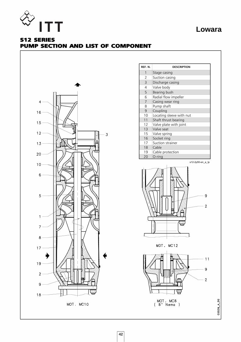
DENOMINAZIONE COMPONENTI
SERIE S12 2 poli 50 Hz
REF. N. DESCRIPTION
1 Stage casing
2 Suction casing
3 Discharge casing
4 Valve body
5 Bearing bush
6 Radial flow impeller
7 Casing wear ring
8 Pump shaft
9 Coupling
10 Locating sleeve with nut
11 Shaft thrust bearing
12 Valve plate with joint
13 Valve seat
15 Valve spring
16 Socket ring
17 Suction strainer
18 Cable
19 Cable protection
20 O-ring
s12-2p50-en_a_tp
S12 SERIESS12 SERIESS12 SERIESS12 SERIESS12 SERIESPUMP SECTION AND LIST OF COMPONENTPUMP SECTION AND LIST OF COMPONENTPUMP SECTION AND LIST OF COMPONENTPUMP SECTION AND LIST OF COMPONENTPUMP SECTION AND LIST OF COMPONENT
43
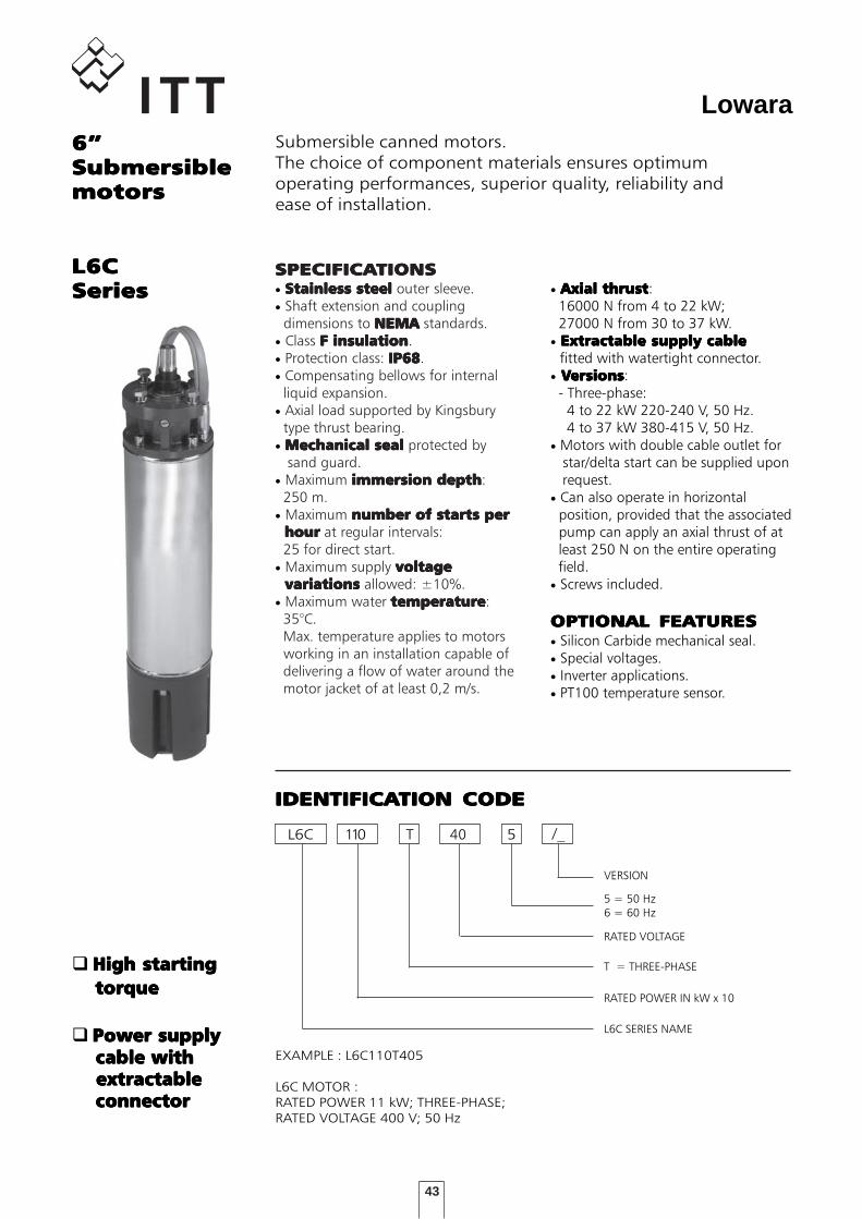
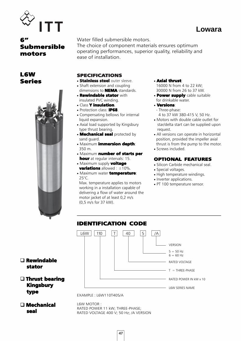
Lowara6”6”6”6”6”SubmersibleSubmersibleSubmersibleSubmersibleSubmersiblemotorsmotorsmotorsmotorsmotors
Submersible canned motors.The choice of component materials ensures optimumoperating performances, superior quality, reliability andease of installation.
L6CL6CL6CL6CL6CSeriesSeriesSeriesSeriesSeries
SPECIFICASPECIFICASPECIFICASPECIFICASPECIFICATIONSTIONSTIONSTIONSTIONS• Stainless steelStainless steelStainless steelStainless steelStainless steel outer sleeve.• Shaft extension and coupling dimensions to NEMANEMANEMANEMANEMA standards.• Class F insulationF insulationF insulationF insulationF insulation.• Protection class: IP68IP68IP68IP68IP68.• Compensating bellows for internal liquid expansion.• Axial load supported by Kingsbury type thrust bearing.• Mechanical sealMechanical sealMechanical sealMechanical sealMechanical seal protected by sand guard.• Maximum immersion depthimmersion depthimmersion depthimmersion depthimmersion depth: 250 m.• Maximum number of starts pernumber of starts pernumber of starts pernumber of starts pernumber of starts per hour hour hour hour hour at regular intervals: 25 for direct start.• Maximum supply voltagevoltagevoltagevoltagevoltage variations variations variations variations variations allowed: ±10%.• Maximum water temperaturetemperaturetemperaturetemperaturetemperature: 35°C. Max. temperature applies to motors working in an installation capable of delivering a flow of water around the motor jacket of at least 0,2 m/s.
• Axial thrustAxial thrustAxial thrustAxial thrustAxial thrust: 16000 N from 4 to 22 kW; 27000 N from 30 to 37 kW.• Extractable supply cableExtractable supply cableExtractable supply cableExtractable supply cableExtractable supply cable fitted with watertight connector.• VVVVVersionsersionsersionsersionsersions: - Three-phase: 4 to 22 kW 220-240 V, 50 Hz. 4 to 37 kW 380-415 V, 50 Hz.• Motors with double cable outlet for star/delta start can be supplied upon request.• Can also operate in horizontal position, provided that the associated pump can apply an axial thrust of at least 250 N on the entire operating field.• Screws included.
OPTIONAL FEAOPTIONAL FEAOPTIONAL FEAOPTIONAL FEAOPTIONAL FEATURESTURESTURESTURESTURES• Silicon Carbide mechanical seal.• Special voltages.• Inverter applications.• PT100 temperature sensor.
L6C 110 5
L6C SERIES NAME
RATED POWER IN kW x 10
T = THREE-PHASE
RATED VOLTAGE
IDENTIFICAIDENTIFICAIDENTIFICAIDENTIFICAIDENTIFICATION CODETION CODETION CODETION CODETION CODE
EXAMPLE : L6C110T405
L6C MOTOR :RATED POWER 11 kW; THREE-PHASE;RATED VOLTAGE 400 V; 50 Hz
T
5 = 50 Hz6 = 60 Hz
40
High startingHigh startingHigh startingHigh startingHigh starting torque torque torque torque torque
Power supplyPower supplyPower supplyPower supplyPower supply cable with cable with cable with cable with cable with extractable extractable extractable extractable extractable connector connector connector connector connector
/_
VERSION
44
Lowara
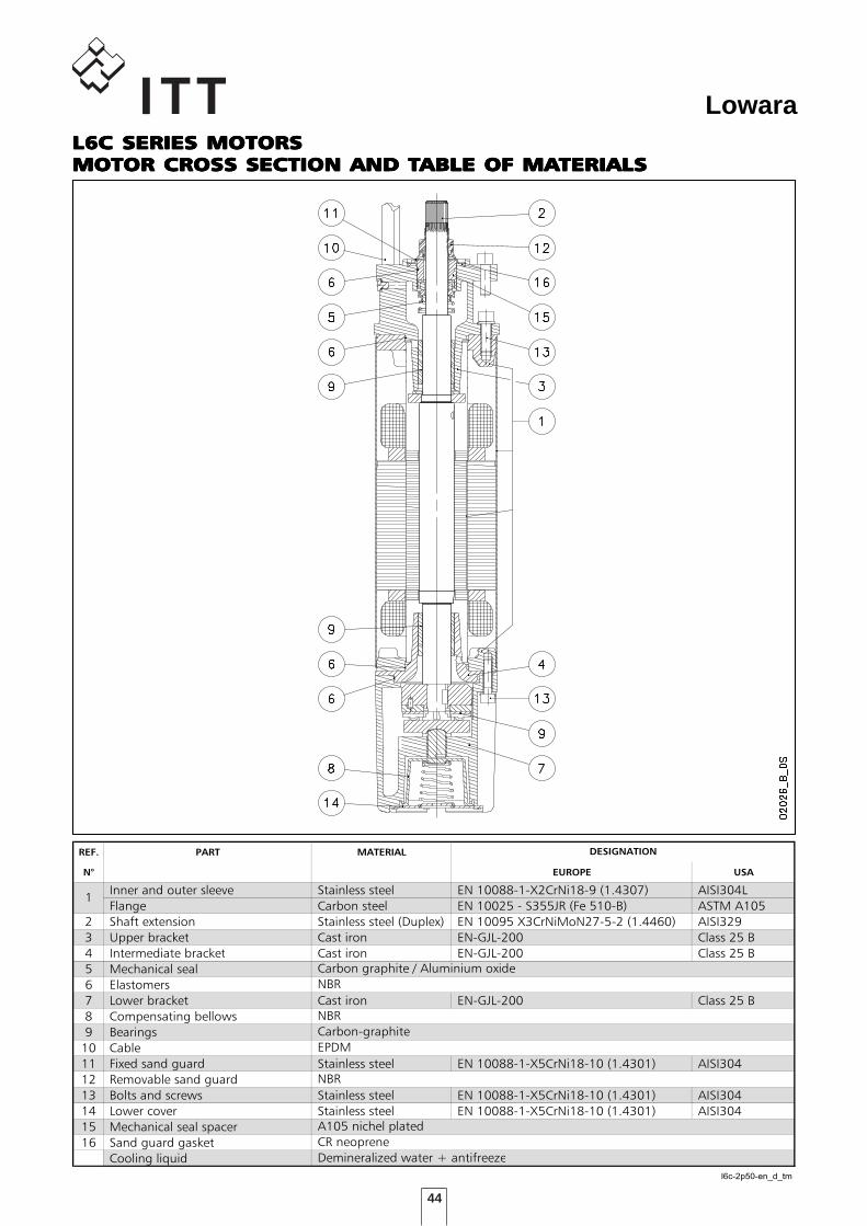
TABELLA MATERIALI L6C
REF. PART MATERIAL
N° EUROPE USA
Inner and outer sleeve Stainless steel EN 10088-1-X2CrNi18-9 (1.4307) AISI304L
Flange Carbon steel EN 10025 - S355JR (Fe 510-B) ASTM A105
2 Shaft extension Stainless steel (Duplex) EN 10095 X3CrNiMoN27-5-2 (1.4460) AISI329
3 Upper bracket Cast iron EN-GJL-200 Class 25 B
4 Intermediate bracket Cast iron EN-GJL-200 Class 25 B
5 Mechanical seal
6 Elastomers
7 Lower bracket Cast iron EN-GJL-200 Class 25 B
8 Compensating bellows
9 Bearings
10 Cable
11 Fixed sand guard Stainless steel EN 10088-1-X5CrNi18-10 (1.4301) AISI304
12 Removable sand guard
13 Bolts and screws Stainless steel EN 10088-1-X5CrNi18-10 (1.4301) AISI304
14 Lower cover Stainless steel EN 10088-1-X5CrNi18-10 (1.4301) AISI304
15 Mechanical seal spacer
16 Sand guard gasket
Cooling liquid
l6c-2p50-en_d_tm
Demineralized water + antifreeze
NBR
A105 nichel plated
CR neoprene
1
EPDM
Carbon-graphite
DESIGNATION
Carbon graphite / Aluminium oxide
NBR
NBR
L6C SERIES MOTORSL6C SERIES MOTORSL6C SERIES MOTORSL6C SERIES MOTORSL6C SERIES MOTORSMOTOR CROSMOTOR CROSMOTOR CROSMOTOR CROSMOTOR CROSS SECTION AND TS SECTION AND TS SECTION AND TS SECTION AND TS SECTION AND TABLE OF MAABLE OF MAABLE OF MAABLE OF MAABLE OF MATERIALSTERIALSTERIALSTERIALSTERIALS
45
Lowara
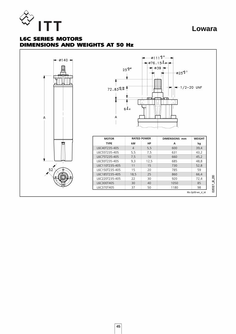
DIMENSIONI E PESI MOTORI L6C - 2 poli 50Hz
MOTOR DIMENSIONS mm WEIGHT
TYPE kW HP A kg
L6C40T235-405 4 5,5 600 39,4
L6C55T235-405 5,5 7,5 631 43,2
L6C75T235-405 7,5 10 660 45,2
L6C93T235-405 9,3 12,5 685 48,8
L6C110T235-405 11 15 730 52,8
L6C150T235-405 15 20 785 59
L6C185T235-405 18,5 25 860 66,4
L6C220T235-405 22 30 920 72,4
L6C300T405 30 40 1050 85
L6C370T405 37 50 1180 98
l6c-2p50-en_d_td
RATED POWER
L6C SERIES MOTORSL6C SERIES MOTORSL6C SERIES MOTORSL6C SERIES MOTORSL6C SERIES MOTORSDIMENSIONS AND WEIGHTS ADIMENSIONS AND WEIGHTS ADIMENSIONS AND WEIGHTS ADIMENSIONS AND WEIGHTS ADIMENSIONS AND WEIGHTS AT 50 HzT 50 HzT 50 HzT 50 HzT 50 Hz
46
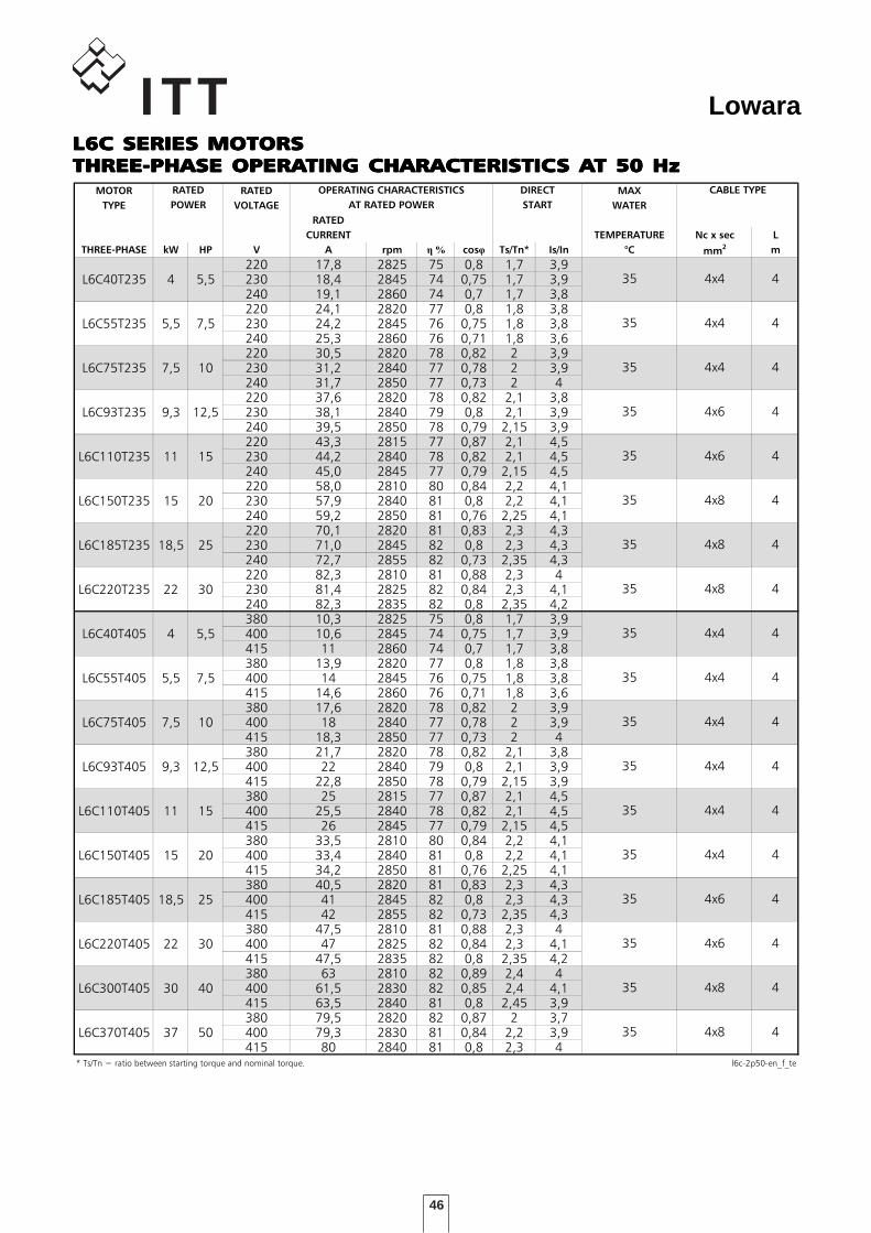
LowaraL6C SERIES MOTORSL6C SERIES MOTORSL6C SERIES MOTORSL6C SERIES MOTORSL6C SERIES MOTORSTHREE-PHASE OPERATHREE-PHASE OPERATHREE-PHASE OPERATHREE-PHASE OPERATHREE-PHASE OPERATING CHARACTERISTICTING CHARACTERISTICTING CHARACTERISTICTING CHARACTERISTICTING CHARACTERISTICS AS AS AS AS AT 50 HzT 50 HzT 50 HzT 50 HzT 50 HzL6C OPERATING CHARACTERISTICS - 50Hz
MOTOR RATED MAX
TYPE VOLTAGE WATER
RATED
CURRENT TEMPERATURE Nc x sec L
THREE-PHASE kW HP V A rpm % cos Ts/Tn* Is/In °C mm2 m
220 17,8 2825 75 0,8 1,7 3,9L6C40T235 4 5,5 230 18,4 2845 74 0,75 1,7 3,9
240 19,1 2860 74 0,7 1,7 3,8220 24,1 2820 77 0,8 1,8 3,8
L6C55T235 5,5 7,5 230 24,2 2845 76 0,75 1,8 3,8240 25,3 2860 76 0,71 1,8 3,6220 30,5 2820 78 0,82 2 3,9
L6C75T235 7,5 10 230 31,2 2840 77 0,78 2 3,9240 31,7 2850 77 0,73 2 4220 37,6 2820 78 0,82 2,1 3,8
L6C93T235 9,3 12,5 230 38,1 2840 79 0,8 2,1 3,9240 39,5 2850 78 0,79 2,15 3,9220 43,3 2815 77 0,87 2,1 4,5
L6C110T235 11 15 230 44,2 2840 78 0,82 2,1 4,5240 45,0 2845 77 0,79 2,15 4,5220 58,0 2810 80 0,84 2,2 4,1
L6C150T235 15 20 230 57,9 2840 81 0,8 2,2 4,1240 59,2 2850 81 0,76 2,25 4,1220 70,1 2820 81 0,83 2,3 4,3
L6C185T235 18,5 25 230 71,0 2845 82 0,8 2,3 4,3240 72,7 2855 82 0,73 2,35 4,3220 82,3 2810 81 0,88 2,3 4
L6C220T235 22 30 230 81,4 2825 82 0,84 2,3 4,1240 82,3 2835 82 0,8 2,35 4,2380 10,3 2825 75 0,8 1,7 3,9
L6C40T405 4 5,5 400 10,6 2845 74 0,75 1,7 3,9415 11 2860 74 0,7 1,7 3,8380 13,9 2820 77 0,8 1,8 3,8
L6C55T405 5,5 7,5 400 14 2845 76 0,75 1,8 3,8415 14,6 2860 76 0,71 1,8 3,6380 17,6 2820 78 0,82 2 3,9
L6C75T405 7,5 10 400 18 2840 77 0,78 2 3,9415 18,3 2850 77 0,73 2 4380 21,7 2820 78 0,82 2,1 3,8
L6C93T405 9,3 12,5 400 22 2840 79 0,8 2,1 3,9415 22,8 2850 78 0,79 2,15 3,9380 25 2815 77 0,87 2,1 4,5
L6C110T405 11 15 400 25,5 2840 78 0,82 2,1 4,5415 26 2845 77 0,79 2,15 4,5380 33,5 2810 80 0,84 2,2 4,1
L6C150T405 15 20 400 33,4 2840 81 0,8 2,2 4,1415 34,2 2850 81 0,76 2,25 4,1380 40,5 2820 81 0,83 2,3 4,3
L6C185T405 18,5 25 400 41 2845 82 0,8 2,3 4,3415 42 2855 82 0,73 2,35 4,3380 47,5 2810 81 0,88 2,3 4
L6C220T405 22 30 400 47 2825 82 0,84 2,3 4,1415 47,5 2835 82 0,8 2,35 4,2380 63 2810 82 0,89 2,4 4
L6C300T405 30 40 400 61,5 2830 82 0,85 2,4 4,1415 63,5 2840 81 0,8 2,45 3,9380 79,5 2820 82 0,87 2 3,7
L6C370T405 37 50 400 79,3 2830 81 0,84 2,2 3,9415 80 2840 81 0,8 2,3 4
* Ts/Tn = ratio between starting torque and nominal torque. l6c-2p50-en_f_te
35 4x8 4
35 4x8 4
35 4x6 4
35 4x8 4
35 4x4 4
35 4x6 4
35 4x4 4
35 4x4 4
35
35
35
35
35
35
4x4 4
4x6
35
35
35
35
4x4
4x4
4
CABLE TYPERATED
POWER
OPERATING CHARACTERISTICS
AT RATED POWER
DIRECT
START
4
4x4 4
4x4
4x4
4
4
4x8
4
4
4
4x6 4
4x8
47
Lowara6”6”6”6”6”SubmersibleSubmersibleSubmersibleSubmersibleSubmersiblemotorsmotorsmotorsmotorsmotors
Water filled submersible motors.The choice of component materials ensures optimumoperating performances, superior quality, reliability andease of installation.
L6WL6WL6WL6WL6WSeriesSeriesSeriesSeriesSeries
SPECIFICASPECIFICASPECIFICASPECIFICASPECIFICATIONSTIONSTIONSTIONSTIONS• Stainless steelStainless steelStainless steelStainless steelStainless steel outer sleeve.• Shaft extension and coupling dimensions to NEMA NEMA NEMA NEMA NEMA standards.• Rewindable statorRewindable statorRewindable statorRewindable statorRewindable stator with insulated PVC winding.• Class YYYYY insulationinsulationinsulationinsulationinsulation.• Protection class: IP68IP68IP68IP68IP68.• Compensating bellows for internal liquid expansion.• Axial load supported by Kingsbury type thrust bearing.• Mechanical sealMechanical sealMechanical sealMechanical sealMechanical seal protected by sand guard.• Maximum immersion depthimmersion depthimmersion depthimmersion depthimmersion depth: 350 m.• Maximum number of starts pernumber of starts pernumber of starts pernumber of starts pernumber of starts per hour hour hour hour hour at regular intervals: 15.• Maximum supply voltagevoltagevoltagevoltagevoltage variationsvariationsvariationsvariationsvariations allowed : ±10%.• Maximum water temperaturetemperaturetemperaturetemperaturetemperature: 25°C. Max. temperature applies to motors working in a installation capable of delivering a flow of water around the motor jacket of at least 0,2 m/s (0,5 m/s for 37 kW).
• Axial thrustAxial thrustAxial thrustAxial thrustAxial thrust: 16000 N from 4 to 22 kW; 30000 N from 26 to 37 kW.• Power supply Power supply Power supply Power supply Power supply cable suitable for drinkable water.• VVVVVersionsersionsersionsersionsersions: - Three-phase: 4 to 37 kW 380-415 V, 50 Hz.• Motors with double cable outlet for star/delta start can be supplied upon request.• All versions can operate in horizontal position, provided the impeller axial thrust is from the pump to the motor.• Screws included.
OPTIONAL FEAOPTIONAL FEAOPTIONAL FEAOPTIONAL FEAOPTIONAL FEATURESTURESTURESTURESTURES• Silicon Carbide mechanical seal.• Special voltages.• High temperature windings.• Inverter applications.• PT 100 temperature sensor.
L6W 110 5
L6W SERIES NAME
RATED POWER IN kW x 10
T = THREE-PHASE
RATED VOLTAGE
IDENTIFICAIDENTIFICAIDENTIFICAIDENTIFICAIDENTIFICATION CODETION CODETION CODETION CODETION CODE
EXAMPLE : L6W110T405/A
L6W MOTOR :RATED POWER 11 kW; THREE-PHASE;RATED VOLTAGE 400 V; 50 Hz; /A VERSION
T
5 = 50 Hz6 = 60 Hz
40
RewindableRewindableRewindableRewindableRewindable stator stator stator stator stator
Thrust bearingThrust bearingThrust bearingThrust bearingThrust bearing Kingsbury Kingsbury Kingsbury Kingsbury Kingsbury type type type type type
MechanicalMechanicalMechanicalMechanicalMechanical seal seal seal seal seal
/A
VERSION
48
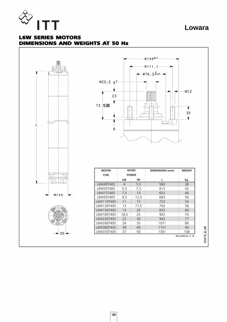
LowaraL6W SERIES MOTORSL6W SERIES MOTORSL6W SERIES MOTORSL6W SERIES MOTORSL6W SERIES MOTORSDIMENSIONS AND WEIGHTS ADIMENSIONS AND WEIGHTS ADIMENSIONS AND WEIGHTS ADIMENSIONS AND WEIGHTS ADIMENSIONS AND WEIGHTS AT 50 HzT 50 HzT 50 HzT 50 HzT 50 Hz
DIMENSIONI E PESI MOTORI L6W - 2 poli 50 Hz
MOTOR DIMENSIONS (mm) WEIGHT
TYPE
kW HP L kg
L6W40T405 4 5,5 583 38
L6W55T405 5,5 7,5 613 42
L6W75T405 7,5 10 653 46
L6W93T405 9,3 12,5 683 50
L6W110T405 11 15 723 54
L6W130T405 13 17,5 763 58
L6W150T405 15 20 833 66
L6W185T405 18,5 25 903 74
L6W220T405 22 30 943 77
L6W260T405 26 35 1071 86
L6W300T405 30 40 1151 94
L6W370T405 37 50 1301 108l6w-2p50-en b td
RATED
POWER
49
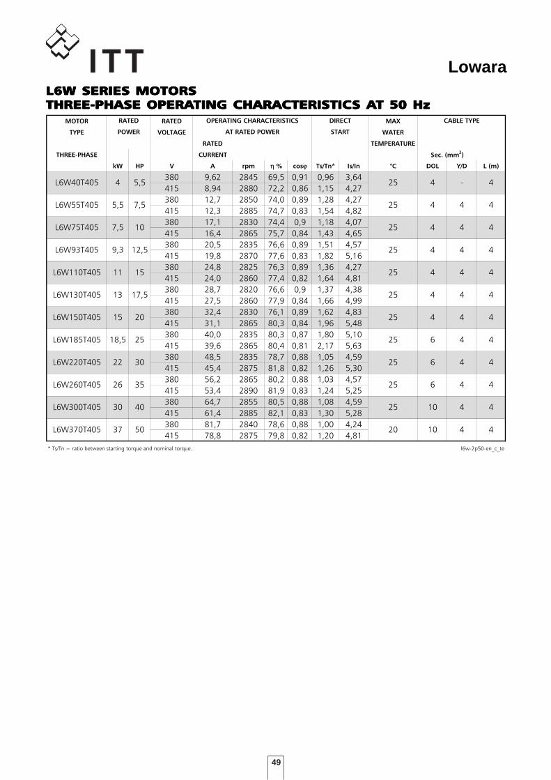
LowaraL6W SERIES MOTORSL6W SERIES MOTORSL6W SERIES MOTORSL6W SERIES MOTORSL6W SERIES MOTORSTHREE-PHASE OPERATHREE-PHASE OPERATHREE-PHASE OPERATHREE-PHASE OPERATHREE-PHASE OPERATING CHARACTERISTICTING CHARACTERISTICTING CHARACTERISTICTING CHARACTERISTICTING CHARACTERISTICS AS AS AS AS AT 50 HzT 50 HzT 50 HzT 50 HzT 50 HzCARATTERISTICHE DI FUNZIONAMENTO A 50 Hz
MOTOR RATED MAX
TYPE VOLTAGE WATER
RATED TEMPERATURE
THREE-PHASE CURRENT
kW HP V A rpm η % cosϕ Ts/Tn* Is/In °C DOL Y/D L (m)
380 9,62 2845 69,5 0,91 0,96 3,64
415 8,94 2880 72,2 0,86 1,15 4,27
380 12,7 2850 74,0 0,89 1,28 4,27
415 12,3 2885 74,7 0,83 1,54 4,82
380 17,1 2830 74,4 0,9 1,18 4,07
415 16,4 2865 75,7 0,84 1,43 4,65
380 20,5 2835 76,6 0,89 1,51 4,57
415 19,8 2870 77,6 0,83 1,82 5,16
380 24,8 2825 76,3 0,89 1,36 4,27
415 24,0 2860 77,4 0,82 1,64 4,81
380 28,7 2820 76,6 0,9 1,37 4,38
415 27,5 2860 77,9 0,84 1,66 4,99
380 32,4 2830 76,1 0,89 1,62 4,83
415 31,1 2865 80,3 0,84 1,96 5,48
380 40,0 2835 80,3 0,87 1,80 5,10
415 39,6 2865 80,4 0,81 2,17 5,63
380 48,5 2835 78,7 0,88 1,05 4,59
415 45,4 2875 81,8 0,82 1,26 5,30
380 56,2 2865 80,2 0,88 1,03 4,57
415 53,4 2890 81,9 0,83 1,24 5,25
380 64,7 2855 80,5 0,88 1,08 4,59
415 61,4 2885 82,1 0,83 1,30 5,28
380 81,7 2840 78,6 0,88 1,00 4,24
415 78,8 2875 79,8 0,82 1,20 4,81
* Ts/Tn = ratio between starting torque and nominal torque. l6w-2p50-en_c_te
CABLE TYPE
4
4
4
4
4
4
4
-
4L6W55T405
L6W75T405
L6W110T405
4
4
4
425
25
25
25
Sec. (mm2)
L6W40T405 4 5,5
5,5 7,5
7,5 10
9,3
RATED
POWER
25
OPERATING CHARACTERISTICS
AT RATED POWER
DIRECT
START
L6W150T405
L6W220T405
L6W93T405
L6W130T405
L6W185T405
12,5
11 15
13 17,5
22 30
25
25
25
25
15 20
18,5 25
L6W260T405 26 35 25
L6W370T405 37 50 20
L6W300T405 30 40 25
4
4
4
4
4
4
4
4
44
4
6
10
4
4
4
4
6
6
10
4
4
4

50
Lowara
51
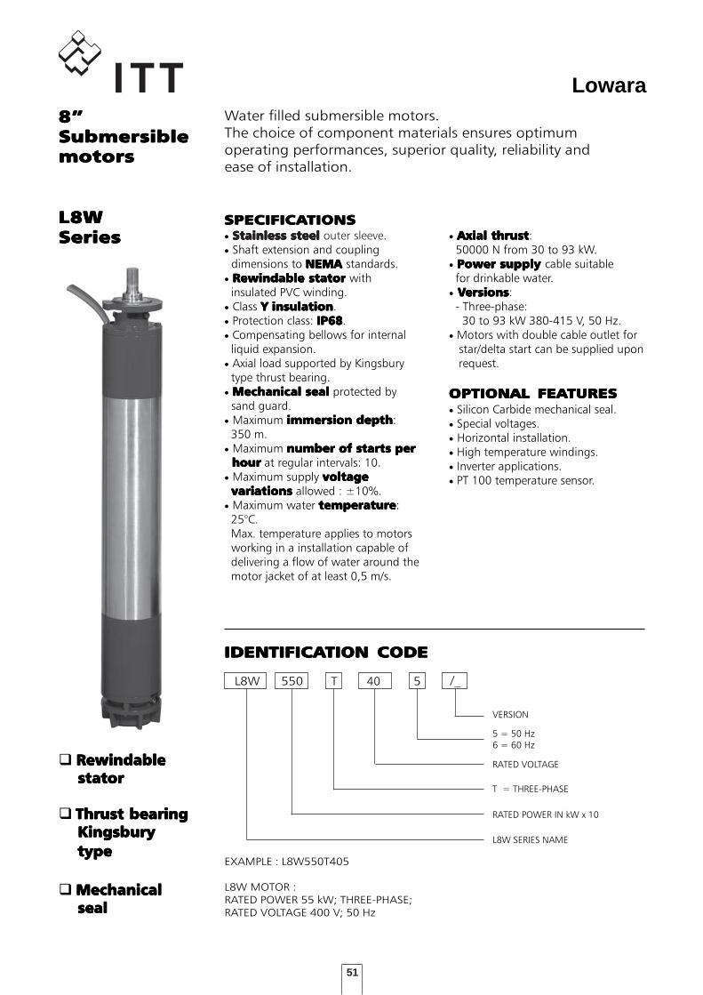
Lowara8”8”8”8”8”SubmersibleSubmersibleSubmersibleSubmersibleSubmersiblemotorsmotorsmotorsmotorsmotors
Water filled submersible motors.The choice of component materials ensures optimumoperating performances, superior quality, reliability andease of installation.
L8WL8WL8WL8WL8WSeriesSeriesSeriesSeriesSeries
SPECIFICASPECIFICASPECIFICASPECIFICASPECIFICATIONSTIONSTIONSTIONSTIONS• Stainless steelStainless steelStainless steelStainless steelStainless steel outer sleeve.• Shaft extension and coupling dimensions to NEMA NEMA NEMA NEMA NEMA standards.• Rewindable statorRewindable statorRewindable statorRewindable statorRewindable stator with insulated PVC winding.• Class YYYYY insulationinsulationinsulationinsulationinsulation.• Protection class: IP68IP68IP68IP68IP68.• Compensating bellows for internal liquid expansion.• Axial load supported by Kingsbury type thrust bearing.• Mechanical sealMechanical sealMechanical sealMechanical sealMechanical seal protected by sand guard.• Maximum immersion depthimmersion depthimmersion depthimmersion depthimmersion depth: 350 m.• Maximum number of starts pernumber of starts pernumber of starts pernumber of starts pernumber of starts per hour hour hour hour hour at regular intervals: 10.• Maximum supply voltagevoltagevoltagevoltagevoltage variationsvariationsvariationsvariationsvariations allowed : ±10%.• Maximum water temperaturetemperaturetemperaturetemperaturetemperature: 25°C. Max. temperature applies to motors working in a installation capable of delivering a flow of water around the motor jacket of at least 0,5 m/s.
• Axial thrustAxial thrustAxial thrustAxial thrustAxial thrust: 50000 N from 30 to 93 kW.• Power supply Power supply Power supply Power supply Power supply cable suitable for drinkable water.• VVVVVersionsersionsersionsersionsersions: - Three-phase: 30 to 93 kW 380-415 V, 50 Hz.• Motors with double cable outlet for star/delta start can be supplied upon request.
OPTIONAL FEAOPTIONAL FEAOPTIONAL FEAOPTIONAL FEAOPTIONAL FEATURESTURESTURESTURESTURES• Silicon Carbide mechanical seal.• Special voltages.• Horizontal installation.• High temperature windings.• Inverter applications.• PT 100 temperature sensor.
L8W 550 5
L8W SERIES NAME
RATED POWER IN kW x 10
T = THREE-PHASE
RATED VOLTAGE
IDENTIFICAIDENTIFICAIDENTIFICAIDENTIFICAIDENTIFICATION CODETION CODETION CODETION CODETION CODE
EXAMPLE : L8W550T405
L8W MOTOR :RATED POWER 55 kW; THREE-PHASE;RATED VOLTAGE 400 V; 50 Hz
T
5 = 50 Hz6 = 60 Hz
40
RewindableRewindableRewindableRewindableRewindable stator stator stator stator stator
Thrust bearingThrust bearingThrust bearingThrust bearingThrust bearing Kingsbury Kingsbury Kingsbury Kingsbury Kingsbury type type type type type
MechanicalMechanicalMechanicalMechanicalMechanical seal seal seal seal seal
/_
VERSION
52
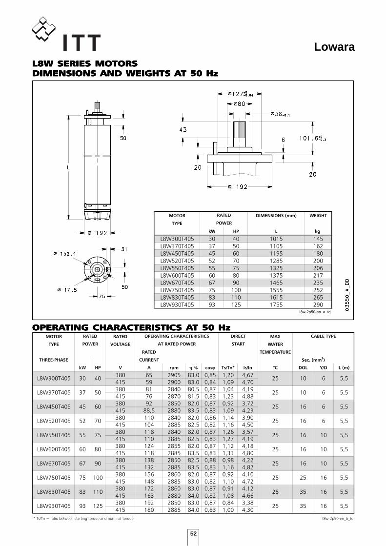
Lowara
OPERAOPERAOPERAOPERAOPERATING CHARACTERISTICTING CHARACTERISTICTING CHARACTERISTICTING CHARACTERISTICTING CHARACTERISTICS AS AS AS AS AT 50 HzT 50 HzT 50 HzT 50 HzT 50 HzCARATTERISTICHE DI FUNZIONAMENTO A 50 Hz
MOTOR RATED MAX
TYPE VOLTAGE WATER
RATED TEMPERATURE
THREE-PHASE CURRENT
kW HP V A rpm η % cosϕ Ts/Tn* Is/In °C DOL Y/D L (m)
380 65 2905 83,0 0,85 1,20 4,67415 59 2900 83,0 0,84 1,09 4,70380 81 2840 80,5 0,87 1,04 4,19415 76 2870 81,5 0,83 1,23 4,88380 92 2850 82,0 0,87 0,92 3,72415 88,5 2880 83,5 0,83 1,09 4,23380 110 2840 82,0 0,86 1,14 3,90415 104 2885 82,5 0,82 1,16 4,50380 118 2840 82,0 0,87 1,26 3,57415 110 2885 82,5 0,83 1,27 4,19380 124 2855 82,0 0,87 1,12 4,18415 118 2885 83,5 0,83 1,33 4,80380 138 2850 82,5 0,88 0,98 4,22415 132 2885 83,5 0,83 1,16 4,82380 156 2860 82,0 0,87 0,92 4,10415 148 2885 83,0 0,82 1,10 4,72380 172 2860 83,0 0,87 0,91 4,12415 163 2880 84,0 0,82 1,08 4,66380 192 2850 83,0 0,87 0,84 3,38415 180 2885 84,0 0,83 1,00 4,30
* Ts/Tn = ratio between starting torque and nominal torque. l8w-2p50-en_b_te
L8W300T405 30 40
25
25
25
25
L8W370T405
L8W450T405
L8W550T405
CABLE TYPERATED
POWER
25
OPERATING CHARACTERISTICS
AT RATED POWER
DIRECT
START
Sec. (mm2)
5,5
L8W670T405
L8W930T405
L8W520T405
L8W600T405
L8W750T405
L8W830T405
37 50
45 60
52 70
55 75
60 80
67 90
75 100
93 125
83 110
25
25
25
25
25 16
5,5
5,5
5,5
5,5
5,5
5,5
5,5
5,5
5,5
10
10
16
16
16
16
16
25
1635
6
6
6
6
10
10
10
16
35
DIMENSIONI E PESI MOTORI L8W - 2 poli 50 Hz
MOTOR DIMENSIONS (mm) WEIGHT
TYPE
kW HP L kg
L8W300T405 30 40 1015 145
L8W370T405 37 50 1105 162
L8W450T405 45 60 1195 180
L8W520T405 52 70 1285 200
L8W550T405 55 75 1325 206
L8W600T405 60 80 1375 217
L8W670T405 67 90 1465 235
L8W750T405 75 100 1555 252
L8W830T405 83 110 1615 265
L8W930T405 93 125 1755 290l8w-2p50-en_a_td
RATED
POWER
L8W SERIES MOTORSL8W SERIES MOTORSL8W SERIES MOTORSL8W SERIES MOTORSL8W SERIES MOTORSDIMENSIONS AND WEIGHTS ADIMENSIONS AND WEIGHTS ADIMENSIONS AND WEIGHTS ADIMENSIONS AND WEIGHTS ADIMENSIONS AND WEIGHTS AT 50 HzT 50 HzT 50 HzT 50 HzT 50 Hz
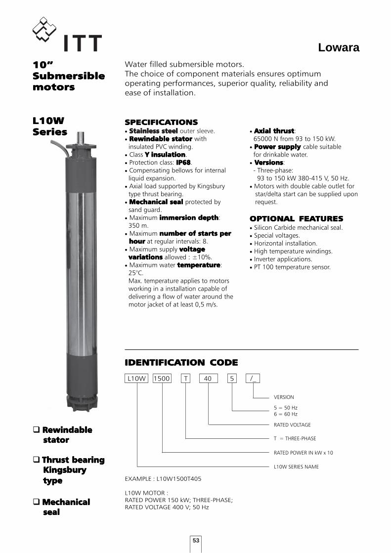
53
Lowara10”10”10”10”10”SubmersibleSubmersibleSubmersibleSubmersibleSubmersiblemotorsmotorsmotorsmotorsmotors
Water filled submersible motors.The choice of component materials ensures optimumoperating performances, superior quality, reliability andease of installation.
SPECIFICASPECIFICASPECIFICASPECIFICASPECIFICATIONSTIONSTIONSTIONSTIONS• Stainless steelStainless steelStainless steelStainless steelStainless steel outer sleeve.• Rewindable statorRewindable statorRewindable statorRewindable statorRewindable stator with insulated PVC winding.• Class YYYYY insulationinsulationinsulationinsulationinsulation.• Protection class: IP68IP68IP68IP68IP68.• Compensating bellows for internal liquid expansion.• Axial load supported by Kingsbury type thrust bearing.• Mechanical sealMechanical sealMechanical sealMechanical sealMechanical seal protected by sand guard.• Maximum immersion depthimmersion depthimmersion depthimmersion depthimmersion depth: 350 m.• Maximum number of starts pernumber of starts pernumber of starts pernumber of starts pernumber of starts per hour hour hour hour hour at regular intervals: 8.• Maximum supply voltagevoltagevoltagevoltagevoltage variationsvariationsvariationsvariationsvariations allowed : ±10%.• Maximum water temperaturetemperaturetemperaturetemperaturetemperature: 25°C. Max. temperature applies to motors working in a installation capable of delivering a flow of water around the motor jacket of at least 0,5 m/s.
• Axial thrustAxial thrustAxial thrustAxial thrustAxial thrust: 65000 N from 93 to 150 kW.• Power supply Power supply Power supply Power supply Power supply cable suitable for drinkable water.• VVVVVersionsersionsersionsersionsersions: - Three-phase: 93 to 150 kW 380-415 V, 50 Hz.• Motors with double cable outlet for star/delta start can be supplied upon request.
OPTIONAL FEAOPTIONAL FEAOPTIONAL FEAOPTIONAL FEAOPTIONAL FEATURESTURESTURESTURESTURES• Silicon Carbide mechanical seal.• Special voltages.• Horizontal installation.• High temperature windings.• Inverter applications.• PT 100 temperature sensor.
L10W 1500 5
L10W SERIES NAME
RATED POWER IN kW x 10
T = THREE-PHASE
RATED VOLTAGE
IDENTIFICAIDENTIFICAIDENTIFICAIDENTIFICAIDENTIFICATION CODETION CODETION CODETION CODETION CODE
EXAMPLE : L10W1500T405
L10W MOTOR :RATED POWER 150 kW; THREE-PHASE;RATED VOLTAGE 400 V; 50 Hz
T
5 = 50 Hz6 = 60 Hz
40
RewindableRewindableRewindableRewindableRewindable stator stator stator stator stator
Thrust bearingThrust bearingThrust bearingThrust bearingThrust bearing Kingsbury Kingsbury Kingsbury Kingsbury Kingsbury type type type type type
MechanicalMechanicalMechanicalMechanicalMechanical seal seal seal seal seal
L10WL10WL10WL10WL10WSeriesSeriesSeriesSeriesSeries
/_
VERSION
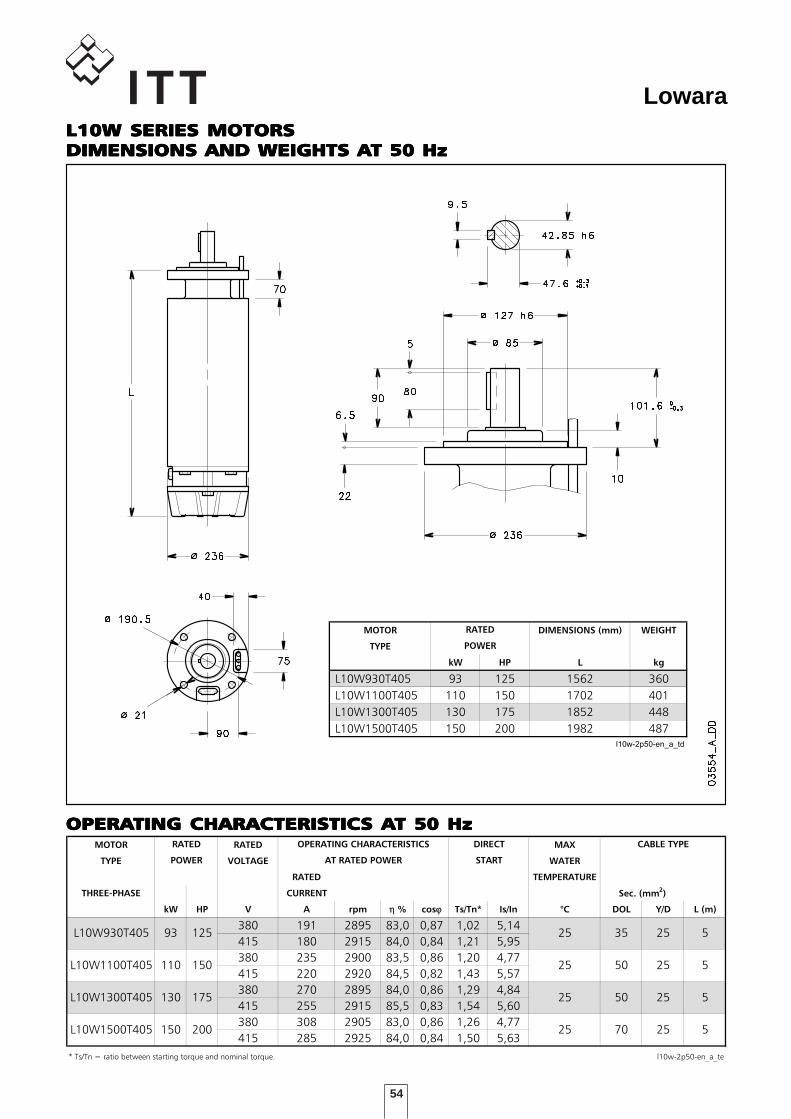
54
Lowara
CARATTERISTICHE DI FUNZIONAMENTO A 50 Hz
MOTOR RATED MAX
TYPE VOLTAGE WATER
RATED TEMPERATURE
THREE-PHASE CURRENT
kW HP V A rpm η % cosϕ Ts/Tn* Is/In °C DOL Y/D L (m)
380 191 2895 83,0 0,87 1,02 5,14
415 180 2915 84,0 0,84 1,21 5,95
380 235 2900 83,5 0,86 1,20 4,77
415 220 2920 84,5 0,82 1,43 5,57
380 270 2895 84,0 0,86 1,29 4,84
415 255 2915 85,5 0,83 1,54 5,60
380 308 2905 83,0 0,86 1,26 4,77
415 285 2925 84,0 0,84 1,50 5,63
* Ts/Tn = ratio between starting torque and nominal torque. l10w-2p50-en_a_te
L10W930T405 93 125
25
25
L10W1100T405
L10W1300T405
L10W1500T405 150 200
110 150
130 25175
CABLE TYPERATED
POWER
25
OPERATING CHARACTERISTICS
AT RATED POWER
DIRECT
START
Sec. (mm2)
35
50
50
70
25
25
25
25
5
5
5
5
DIMENSIONI E PESI MOTORI L10W - 2 poli 50 Hz
MOTOR DIMENSIONS (mm) WEIGHT
TYPE
kW HP L kg
L10W930T405 93 125 1562 360
L10W1100T405 110 150 1702 401
L10W1300T405 130 175 1852 448
L10W1500T405 150 200 1982 487l10w-2p50-en_a_td
RATED
POWER
OPERAOPERAOPERAOPERAOPERATING CHARACTERISTICTING CHARACTERISTICTING CHARACTERISTICTING CHARACTERISTICTING CHARACTERISTICS AS AS AS AS AT 50 HzT 50 HzT 50 HzT 50 HzT 50 Hz
L10W SERIES MOTORSL10W SERIES MOTORSL10W SERIES MOTORSL10W SERIES MOTORSL10W SERIES MOTORSDIMENSIONS AND WEIGHTS ADIMENSIONS AND WEIGHTS ADIMENSIONS AND WEIGHTS ADIMENSIONS AND WEIGHTS ADIMENSIONS AND WEIGHTS AT 50 HzT 50 HzT 50 HzT 50 HzT 50 Hz
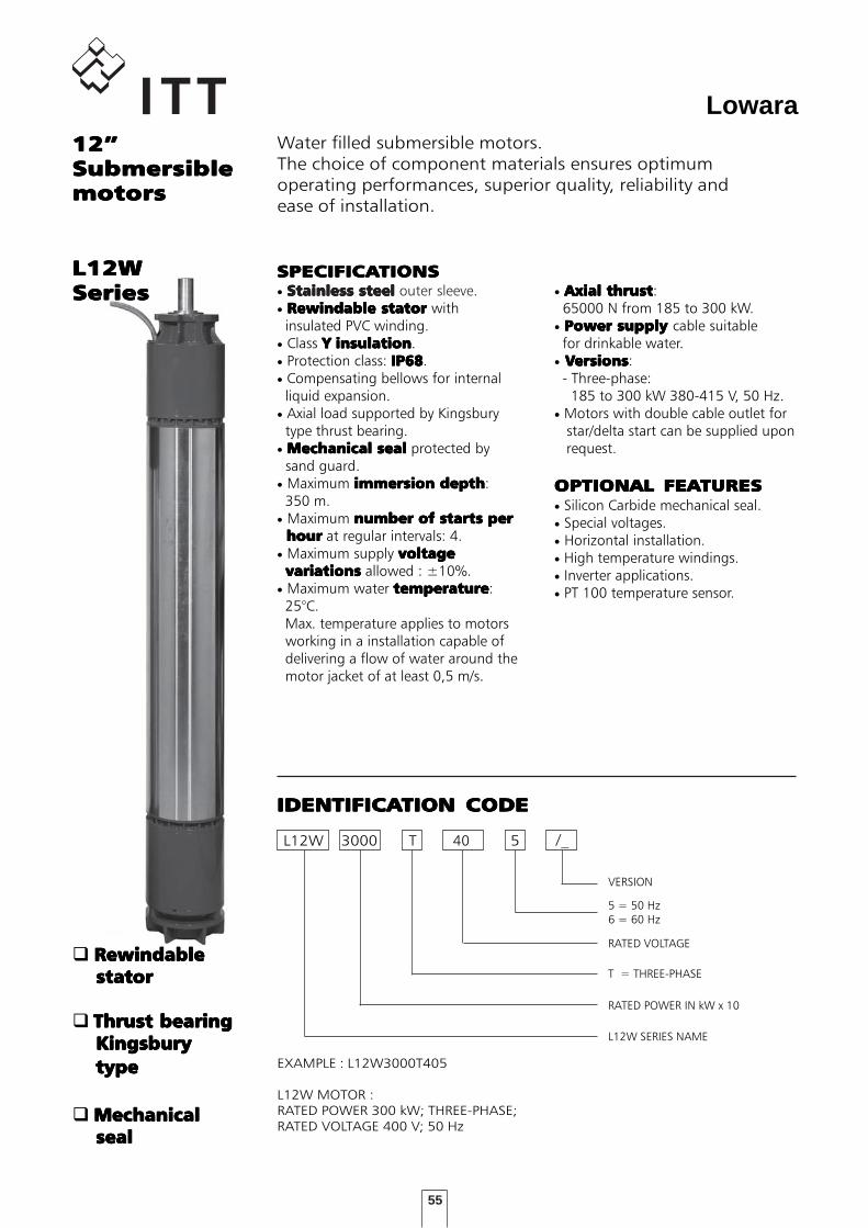
55
Lowara12”12”12”12”12”SubmersibleSubmersibleSubmersibleSubmersibleSubmersiblemotorsmotorsmotorsmotorsmotors
Water filled submersible motors.The choice of component materials ensures optimumoperating performances, superior quality, reliability andease of installation.
L12W 3000 5
L12W SERIES NAME
RATED POWER IN kW x 10
T = THREE-PHASE
RATED VOLTAGE
IDENTIFICAIDENTIFICAIDENTIFICAIDENTIFICAIDENTIFICATION CODETION CODETION CODETION CODETION CODE
EXAMPLE : L12W3000T405
L12W MOTOR :RATED POWER 300 kW; THREE-PHASE;RATED VOLTAGE 400 V; 50 Hz
T
5 = 50 Hz6 = 60 Hz
40
SPECIFICASPECIFICASPECIFICASPECIFICASPECIFICATIONSTIONSTIONSTIONSTIONS• Stainless steelStainless steelStainless steelStainless steelStainless steel outer sleeve.• Rewindable statorRewindable statorRewindable statorRewindable statorRewindable stator with insulated PVC winding.• Class YYYYY insulationinsulationinsulationinsulationinsulation.• Protection class: IP68IP68IP68IP68IP68.• Compensating bellows for internal liquid expansion.• Axial load supported by Kingsbury type thrust bearing.• Mechanical sealMechanical sealMechanical sealMechanical sealMechanical seal protected by sand guard.• Maximum immersion depthimmersion depthimmersion depthimmersion depthimmersion depth: 350 m.• Maximum number of starts pernumber of starts pernumber of starts pernumber of starts pernumber of starts per hour hour hour hour hour at regular intervals: 4.• Maximum supply voltagevoltagevoltagevoltagevoltage variationsvariationsvariationsvariationsvariations allowed : ±10%.• Maximum water temperaturetemperaturetemperaturetemperaturetemperature: 25°C. Max. temperature applies to motors working in a installation capable of delivering a flow of water around the motor jacket of at least 0,5 m/s.
• Axial thrustAxial thrustAxial thrustAxial thrustAxial thrust: 65000 N from 185 to 300 kW.• Power supply Power supply Power supply Power supply Power supply cable suitable for drinkable water.• VVVVVersionsersionsersionsersionsersions: - Three-phase: 185 to 300 kW 380-415 V, 50 Hz.• Motors with double cable outlet for star/delta start can be supplied upon request.
OPTIONAL FEAOPTIONAL FEAOPTIONAL FEAOPTIONAL FEAOPTIONAL FEATURESTURESTURESTURESTURES• Silicon Carbide mechanical seal.• Special voltages.• Horizontal installation.• High temperature windings.• Inverter applications.• PT 100 temperature sensor.
L12WL12WL12WL12WL12WSeriesSeriesSeriesSeriesSeries
RewindableRewindableRewindableRewindableRewindable stator stator stator stator stator
Thrust bearingThrust bearingThrust bearingThrust bearingThrust bearing Kingsbury Kingsbury Kingsbury Kingsbury Kingsbury type type type type type
MechanicalMechanicalMechanicalMechanicalMechanical seal seal seal seal seal
/_
VERSION
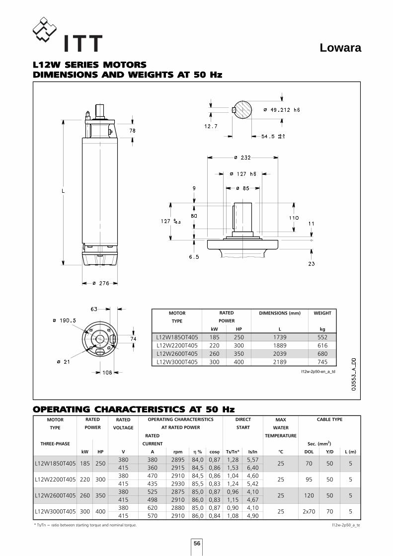
56
Lowara
CARATTERISTICHE DI FUNZIONAMENTO A 50 Hz
MOTOR RATED MAX
TYPE VOLTAGE WATER
RATED TEMPERATURE
THREE-PHASE CURRENT
kW HP V A rpm η % cosϕ Ts/Tn* Is/In °C DOL Y/D L (m)
380 380 2895 84,0 0,87 1,28 5,57
415 360 2915 84,5 0,86 1,53 6,40
380 470 2910 84,5 0,86 1,04 4,60
415 435 2930 85,5 0,83 1,24 5,42
380 525 2875 85,0 0,87 0,96 4,10
415 498 2910 86,0 0,83 1,15 4,67
380 620 2880 85,0 0,87 0,90 4,10
415 570 2910 86,0 0,84 1,08 4,90
* Ts/Tn = ratio between starting torque and nominal torque. l12w-2p50_a_te
50
50
50
70
70
95
120
2x70
5
5
5
5300
CABLE TYPERATED
POWER
25
OPERATING CHARACTERISTICS
AT RATED POWER
DIRECT
START
Sec. (mm2)
220 300
260 350
25
400
L12W1850T405 185 250
25
25
L12W2200T405
L12W2600T405
L12W3000T405
DIMENSIONI E PESI MOTORI L12W - 2 poli 50 Hz
MOTOR DIMENSIONS (mm) WEIGHT
TYPE
kW HP L kg
L12W185OT405 185 250 1739 552
L12W2200T405 220 300 1889 616
L12W2600T405 260 350 2039 680
L12W3000T405 300 400 2189 745
l12w-2p50-en_a_td
RATED
POWER
OPERAOPERAOPERAOPERAOPERATING CHARACTERISTICTING CHARACTERISTICTING CHARACTERISTICTING CHARACTERISTICTING CHARACTERISTICS AS AS AS AS AT 50 HzT 50 HzT 50 HzT 50 HzT 50 Hz
L12W SERIES MOTORSL12W SERIES MOTORSL12W SERIES MOTORSL12W SERIES MOTORSL12W SERIES MOTORSDIMENSIONS AND WEIGHTS ADIMENSIONS AND WEIGHTS ADIMENSIONS AND WEIGHTS ADIMENSIONS AND WEIGHTS ADIMENSIONS AND WEIGHTS AT 50 HzT 50 HzT 50 HzT 50 HzT 50 Hz
57
Lowara
ISO Threaded Flange .......................................................................................................................5858585858
Supporting Collars ..........................................................................................................................6060606060
Motor - Control Panel Combination Table ........................................................................................6161616161
Electrical Panels ...............................................................................................................................6363636363
Level control panels ........................................................................................................................6969696969
Level probe module ........................................................................................................................7070707070
Lightning protection .......................................................................................................................7171717171
ACCESACCESACCESACCESACCESSORIESSORIESSORIESSORIESSORIES
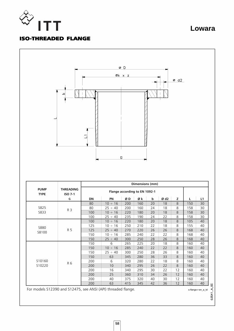
58
LowaraISOISOISOISOISO-----THREADED FLANGETHREADED FLANGETHREADED FLANGETHREADED FLANGETHREADED FLANGE
DIMENSIONI FLANGE ISO PER POMPE SERIE S
PUMP THREADING
TYPE ISO 7-1
G DN PN Ø D Ø k b Ø d2 Z L L1
80 10 ÷ 16 200 160 20 18 8 150 30
80 25 ÷ 40 200 160 24 18 8 158 30
100 10 ÷ 16 220 180 20 18 8 158 30
100 25 ÷ 40 235 190 24 22 8 158 30
100 10 ÷ 16 220 180 20 18 8 105 40
125 10 ÷ 16 250 210 22 18 8 155 40
125 25 ÷ 40 270 220 26 26 8 168 40
150 10 ÷ 16 285 240 22 22 8 168 40
150 25 ÷ 40 300 250 28 26 8 168 40
150 6 265 225 20 18 8 160 40
150 10 ÷ 16 285 240 22 22 8 160 40
150 25 ÷ 40 300 250 28 26 8 160 40
150 63 345 280 36 33 8 160 40
200 6 320 280 22 18 8 160 40
200 10 340 295 26 22 8 160 40
200 16 340 295 30 22 12 160 40
200 25 360 310 34 26 12 160 40
200 40 375 320 40 30 12 160 40
200 63 415 345 42 36 12 160 40
For models S12390 and S12475, see ANSI (API) threaded flange. s-flange-r-en_a_td
Dimensions (mm)
Flange according to EN 1092-1
S10160
S10220
S880
S8100
S825
S833 R 3
R 5
R 6
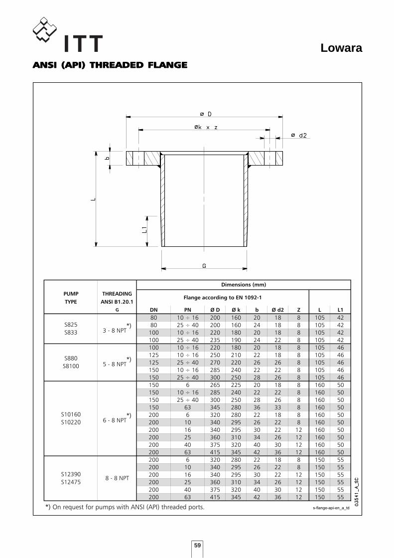
59
LowaraANSI (API) THREADED FLANGEANSI (API) THREADED FLANGEANSI (API) THREADED FLANGEANSI (API) THREADED FLANGEANSI (API) THREADED FLANGE
DIMENSIONI FLANGE ANSI (API) POMPE SERIE S
PUMP THREADING
TYPE ANSI B1.20.1
G DN PN Ø D Ø k b Ø d2 Z L L1
80 10 ÷ 16 200 160 20 18 8 105 42
80 25 ÷ 40 200 160 24 18 8 105 42
100 10 ÷ 16 220 180 20 18 8 105 42
100 25 ÷ 40 235 190 24 22 8 105 42
100 10 ÷ 16 220 180 20 18 8 105 46
125 10 ÷ 16 250 210 22 18 8 105 46
125 25 ÷ 40 270 220 26 26 8 105 46
150 10 ÷ 16 285 240 22 22 8 105 46
150 25 ÷ 40 300 250 28 26 8 105 46
150 6 265 225 20 18 8 160 50
150 10 ÷ 16 285 240 22 22 8 160 50
150 25 ÷ 40 300 250 28 26 8 160 50
150 63 345 280 36 33 8 160 50
200 6 320 280 22 18 8 160 50
200 10 340 295 26 22 8 160 50
200 16 340 295 30 22 12 160 50
200 25 360 310 34 26 12 160 50
200 40 375 320 40 30 12 160 50
200 63 415 345 42 36 12 160 50
200 6 320 280 22 18 8 150 55
200 10 340 295 26 22 8 150 55
200 16 340 295 30 22 12 150 55
200 25 360 310 34 26 12 150 55
200 40 375 320 40 30 12 150 55
200 63 415 345 42 36 12 150 55
*) On request for pumps with ANSI (API) threaded ports. s-flange-api-en_a_td
Dimensions (mm)
Flange according to EN 1092-1
S12390
S124758 - 8 NPT
S10160
S10220
S880
S8100
S825
S833 3 - 8 NPT*)
5 - 8 NPT*)
6 - 8 NPT*)
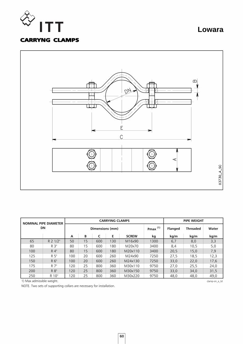
60
LowaraCARRYNG CLAMPSCARRYNG CLAMPSCARRYNG CLAMPSCARRYNG CLAMPSCARRYNG CLAMPS
DIMENSIONI CLAMP PER POMPE SOMMERSE
A B C E SCREW kg kg/m kg/m kg/m
65 R 2 1/2" 50 15 600 130 M16x90 1300 6,7 8,0 3,3
80 R 3" 80 15 600 180 M20x70 3400 8,4 10,5 5,0
100 R 4" 80 15 600 180 M20x110 3400 20,5 15,0 7,9
125 R 5" 100 20 600 260 M24x90 7250 27,5 18,5 12,3
150 R 6" 100 20 600 260 M24x130 7250 33,0 22,0 17,6
175 R 7" 120 25 800 360 M30x110 9750 27,0 25,5 24,0
200 R 8" 120 25 800 360 M30x150 9750 33,0 34,0 31,5
250 R 10" 120 25 800 360 M30x220 9750 48,0 48,0 49,0
1) Max admissible weight. clamp-en_a_td
NOTE. Two sets of supporting collars are necessary for installation.
NOMINAL PIPE DIAMETER
DN Pmax (1) Threaded Water
PIPE WEIGHTCARRYING CLAMPS
Dimensions (mm) Flanged
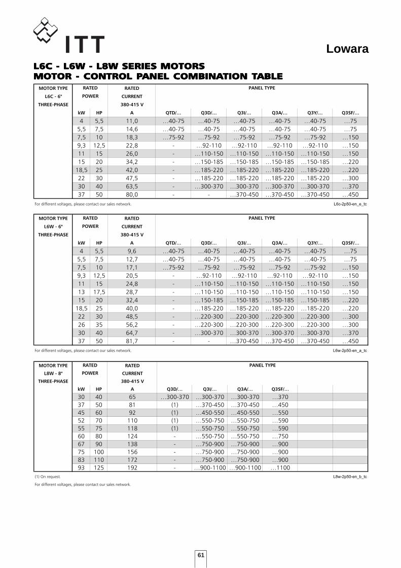
61
LowaraL6C - L6W - L8W SERIES MOTORSL6C - L6W - L8W SERIES MOTORSL6C - L6W - L8W SERIES MOTORSL6C - L6W - L8W SERIES MOTORSL6C - L6W - L8W SERIES MOTORSMOTOR - CONTROL PMOTOR - CONTROL PMOTOR - CONTROL PMOTOR - CONTROL PMOTOR - CONTROL PANEL COMBINAANEL COMBINAANEL COMBINAANEL COMBINAANEL COMBINATION TTION TTION TTION TTION TABLEABLEABLEABLEABLETABELLE INDICATIVE DI ABBINAMENTO MOTORE - QUADRO
MOTOR TYPE RATED
L6C - 6" CURRENT
THREE-PHASE 380-415 V
kW HP A QTD/… Q3D/… Q3I/… Q3A/… Q3Y/… Q3SF/…
4 5,5 11,0 …40-75 …40-75 …40-75 …40-75 …40-75 …75
5,5 7,5 14,6 …40-75 …40-75 …40-75 …40-75 …40-75 …75
7,5 10 18,3 …75-92 …75-92 …75-92 …75-92 …75-92 …150
9,3 12,5 22,8 - …92-110 …92-110 …92-110 …92-110 …150
11 15 26,0 - …110-150 …110-150 …110-150 …110-150 …150
15 20 34,2 - …150-185 …150-185 …150-185 …150-185 …220
18,5 25 42,0 - …185-220 …185-220 …185-220 …185-220 …220
22 30 47,5 - …185-220 …185-220 …185-220 …185-220 …300
30 40 63,5 - …300-370 …300-370 …300-370 …300-370 …370
37 50 80,0 - - …370-450 …370-450 …370-450 …450
For different voltages, please contact our sales network. L6c-2p50-en_e_tc
POWER
RATED PANEL TYPE
TABELLE INDICATIVE DI ABBINAMENTO MOTORE - QUADRO
MOTOR TYPE RATED
L6W - 6" CURRENT
THREE-PHASE 380-415 V
kW HP A QTD/… Q3D/… Q3I/… Q3A/… Q3Y/… Q3SF/…
4 5,5 9,6 …40-75 …40-75 …40-75 …40-75 …40-75 …75
5,5 7,5 12,7 …40-75 …40-75 …40-75 …40-75 …40-75 …75
7,5 10 17,1 …75-92 …75-92 …75-92 …75-92 …75-92 …150
9,3 12,5 20,5 - …92-110 …92-110 …92-110 …92-110 …150
11 15 24,8 - …110-150 …110-150 …110-150 …110-150 …150
13 17,5 28,7 - …110-150 …110-150 …110-150 …110-150 …150
15 20 32,4 - …150-185 …150-185 …150-185 …150-185 …220
18,5 25 40,0 - …185-220 …185-220 …185-220 …185-220 …220
22 30 48,5 - …220-300 …220-300 …220-300 …220-300 …300
26 35 56,2 - …220-300 …220-300 …220-300 …220-300 …300
30 40 64,7 - …300-370 …300-370 …300-370 …300-370 …370
37 50 81,7 - - …370-450 …370-450 …370-450 …450
For different voltages, please contact our sales network. L6w-2p50-en_a_tc
POWER
RATED PANEL TYPE
TABELLA ABBINAMENTO POMPA-QUADRO COMANDO
MOTOR TYPE RATED
L8W - 8" CURRENT
THREE-PHASE 380-415 V
kW HP A Q3D/… Q3I/… Q3A/… Q3SF/…
30 40 65 …300-370 …300-370 …300-370 …370
37 50 81 (1) …370-450 …370-450 …450
45 60 92 (1) …450-550 …450-550 …550
52 70 110 (1) …550-750 …550-750 …590
55 75 118 (1) …550-750 …550-750 …590
60 80 124 - …550-750 …550-750 …750
67 90 138 - …750-900 …750-900 …900
75 100 156 - …750-900 …750-900 …900
83 110 172 - …750-900 …750-900 …900
93 125 192 - …900-1100 …900-1100 …1100
(1) On request. L8w-2p50-en_b_tc
For different voltages, please contact our sales network.
POWER
RATED PANEL TYPE
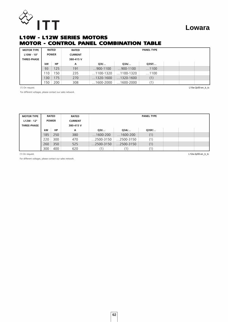
62
LowaraL10W - L12W SERIES MOTORSL10W - L12W SERIES MOTORSL10W - L12W SERIES MOTORSL10W - L12W SERIES MOTORSL10W - L12W SERIES MOTORSMOTOR - CONTROL PMOTOR - CONTROL PMOTOR - CONTROL PMOTOR - CONTROL PMOTOR - CONTROL PANEL COMBINAANEL COMBINAANEL COMBINAANEL COMBINAANEL COMBINATION TTION TTION TTION TTION TABLEABLEABLEABLEABLETABELLA ABBINAMENTO POMPA-QUADRO COMANDO
MOTOR TYPE RATED
L10W - 10" CURRENT
THREE-PHASE 380-415 V
kW HP A Q3I/… Q3A/… Q3SF/…
93 125 191 …900-1100 …900-1100 …1100
110 150 235 …1100-1320 …1100-1320 …1100
130 175 270 …1320-1600 …1320-1600 (1)
150 200 308 …1600-2000 …1600-2000 (1)
(1) On request. L10w-2p50-en_b_tc
For different voltages, please contact our sales network.
RATED PANEL TYPE
POWER
TABELLA ABBINAMENTO POMPA-QUADRO COMANDO
MOTOR TYPE RATED
L12W - 12" CURRENT
THREE-PHASE 380-415 V
kW HP A Q3I/… Q3A/… Q3SF/…
185 250 380 …1600-200 …1600-200 (1)
220 300 470 …2500-3150 …2500-3150 (1)
260 350 525 …2500-3150 …2500-3150 (1)
300 400 620 (1) (1) (1)
(1) On request. L12w-2p50-en_b_tc
For different voltages, please contact our sales network.
RATED
POWER
PANEL TYPE
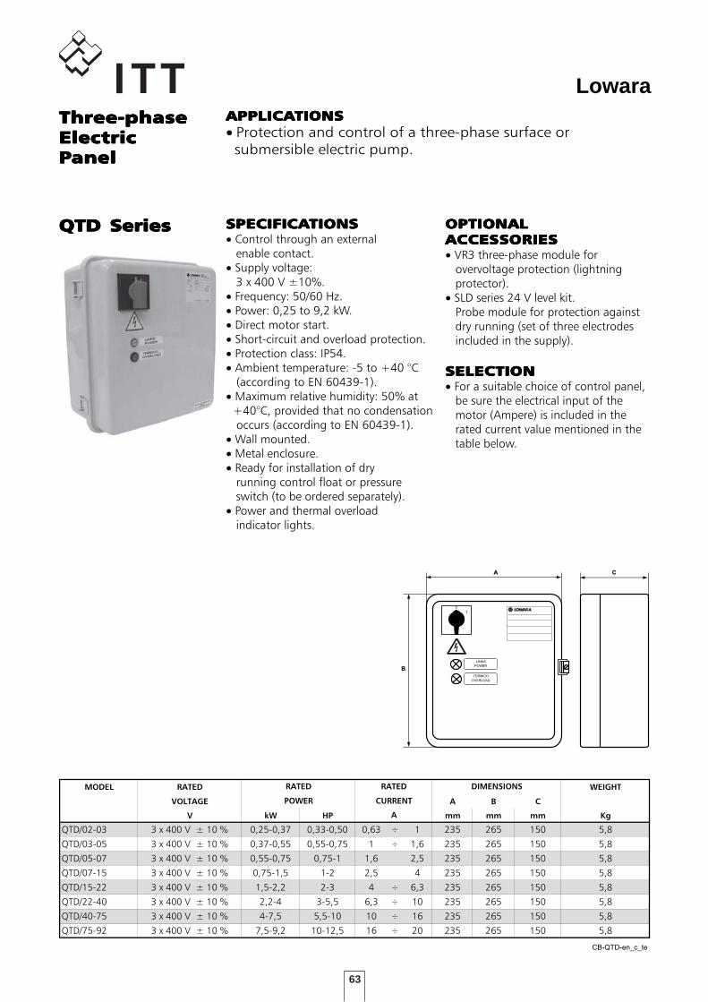
63
LowaraThree-phaseThree-phaseThree-phaseThree-phaseThree-phaseElectricElectricElectricElectricElectricPPPPPanelanelanelanelanel
QTD SeriesQTD SeriesQTD SeriesQTD SeriesQTD Series
APPLICAAPPLICAAPPLICAAPPLICAAPPLICATIONSTIONSTIONSTIONSTIONS• Protection and control of a three-phase surface or submersible electric pump.
SERIE QTD
MODEL RATED WEIGHT
VOLTAGE A B C
V kW HP mm mm mm Kg
QTD/02-03 3 x 400 V ± 10 % 0,25-0,37 0,33-0,50 0,63 ÷ 1 235 265 150 5,8
QTD/03-05 3 x 400 V ± 10 % 0,37-0,55 0,55-0,75 1 ÷ 1,6 235 265 150 5,8
QTD/05-07 3 x 400 V ± 10 % 0,55-0,75 0,75-1 1,6 2,5 235 265 150 5,8
QTD/07-15 3 x 400 V ± 10 % 0,75-1,5 1-2 2,5 4 235 265 150 5,8
QTD/15-22 3 x 400 V ± 10 % 1,5-2,2 2-3 4 ÷ 6,3 235 265 150 5,8
QTD/22-40 3 x 400 V ± 10 % 2,2-4 3-5,5 6,3 ÷ 10 235 265 150 5,8
QTD/40-75 3 x 400 V ± 10 % 4-7,5 5,5-10 10 ÷ 16 235 265 150 5,8
QTD/75-92 3 x 400 V ± 10 % 7,5-9,2 10-12,5 16 ÷ 20 235 265 150 5,8
CB-QTD-en_c_te
A
RATED
POWER
DIMENSIONSRATED
CURRENT
OPTIONALOPTIONALOPTIONALOPTIONALOPTIONALACCESACCESACCESACCESACCESSORIESSORIESSORIESSORIESSORIES• VR3 three-phase module for overvoltage protection (lightning protector).• SLD series 24 V level kit. Probe module for protection against dry running (set of three electrodes included in the supply).
SELECTIONSELECTIONSELECTIONSELECTIONSELECTION• For a suitable choice of control panel, be sure the electrical input of the motor (Ampere) is included in the rated current value mentioned in the table below.
A
B
C
0
1
LINEA
POWER
TERMICO
OVERLOAD
SPECIFICASPECIFICASPECIFICASPECIFICASPECIFICATIONSTIONSTIONSTIONSTIONS• Control through an external enable contact.• Supply voltage: 3 x 400 V ±10%.• Frequency: 50/60 Hz.• Power: 0,25 to 9,2 kW.• Direct motor start.• Short-circuit and overload protection.• Protection class: IP54.• Ambient temperature: -5 to +40 °C (according to EN 60439-1).• Maximum relative humidity: 50% at +40°C, provided that no condensation occurs (according to EN 60439-1).• Wall mounted.• Metal enclosure.• Ready for installation of dry running control float or pressure switch (to be ordered separately).• Power and thermal overload indicator lights.
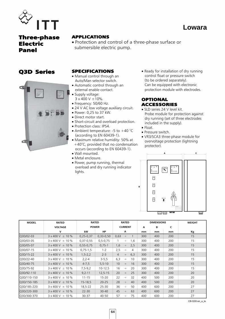
64
Lowara
• Ready for installation of dry running control float or pressure switch (to be ordered separately). Can be equipped with electronic protection module with electrodes.
OPTIONALOPTIONALOPTIONALOPTIONALOPTIONALACCESACCESACCESACCESACCESSORIESSORIESSORIESSORIESSORIES• SLD series 24 V level kit. Probe module for protection against dry running (set of three electrodes included in the supply).• Float.• Pressure switch.• VR3/SCA3 three-phase module for overvoltage protection (lightning protector).
Three-phaseThree-phaseThree-phaseThree-phaseThree-phaseElectricElectricElectricElectricElectricPPPPPanelanelanelanelanel
APPLICAAPPLICAAPPLICAAPPLICAAPPLICATIONSTIONSTIONSTIONSTIONS• Protection and control of a three-phase surface or submersible electric pump.
SERIE Q3D
MODEL RATED WEIGHT
VOLTAGE A B C
V kW HP mm mm mm Kg
Q3D/02-03 3 x 400 V ± 10 % 0,25-0,37 0,33-0,50 0,63 ÷ 1 300 400 200 15
Q3D/03-05 3 x 400 V ± 10 % 0,37-0,55 0,5-0,75 1 ÷ 1,6 300 400 200 15
Q3D/05-07 3 x 400 V ± 10 % 0,55-0,75 0,75-1 1,6 ÷ 2,5 300 400 200 15
Q3D/07-15 3 x 400 V ± 10 % 0,75-1,5 1-2 2,5 ÷ 4 300 400 200 15
Q3D/15-22 3 x 400 V ± 10 % 1,5-2,2 2-3 4 ÷ 6,3 300 400 200 15
Q3D/22-40 3 x 400 V ± 10 % 2,2-4 3-5,5 6,3 ÷ 10 300 400 200 15
Q3D/40-75 3 x 400 V ± 10 % 4-7,5 5,5-10 10 ÷ 16 300 400 200 15
Q3D/75-92 3 x 400 V ± 10 % 7,5-9,2 10-12,5 16 ÷ 20 300 400 200 15
Q3D/92-110 3 x 400 V ± 10 % 9,2-11 12,5-15 20 ÷ 25 300 400 200 20
Q3D/110-150 3 x 400 V ± 10 % 11-15 15-20 22 ÷ 32 400 500 200 20
Q3D/150-185 3 x 400 V ± 10 % 15-18,5 20-25 28 ÷ 40 400 500 200 20
Q3D/185-220 3 x 400 V ± 10 % 18,5-22 25-30 36 ÷ 50 400 600 200 27
Q3D/220-300 3 x 400 V ± 10 % 22-30 30-40 45 ÷ 63 400 600 200 27
Q3D/300-370 3 x 400 V ± 10 % 30-37 40-50 57 ÷ 75 400 600 200 27
CB-Q3D-en_a_te
A
RATED
POWER
DIMENSIONSRATED
CURRENT
Q3D SeriesQ3D SeriesQ3D SeriesQ3D SeriesQ3D Series
0
200
150A
25
0
V 500
300
50 0
L1-L2
L2-L3
L3-L1
0M A
A
B
C
SPECIFICASPECIFICASPECIFICASPECIFICASPECIFICATIONSTIONSTIONSTIONSTIONS• Manual control through an Auto/Man selector switch.• Automatic control through an external enable contact.• Supply voltage: 3 x 400 V ±10%.• Frequency: 50/60 Hz.• 24 V AC low voltage auxiliary circuit.• Power: 0,25 to 37 kW.• Direct motor start.• Short-circuit and overload protection.• Protection class: IP54.• Ambient temperature: -5 to +40 °C (according to EN 60439-1).• Maximum relative humidity: 50% at +40°C, provided that no condensation occurs (according to EN 60439-1).• Wall mounted.• Metal enclosure.• Power, pump running, thermal overload and dry running indicator lights.

65
LowaraThree-phaseThree-phaseThree-phaseThree-phaseThree-phaseElectricElectricElectricElectricElectricPPPPPanelanelanelanelanel
Q3Y SeriesQ3Y SeriesQ3Y SeriesQ3Y SeriesQ3Y Series
APPLICAAPPLICAAPPLICAAPPLICAAPPLICATIONSTIONSTIONSTIONSTIONS• Protection and control of a three-phase surface or submersible electric pump.
SERIE Q3Y
MODEL RATED WEIGHT
VOLTAGE A B C
V kW HP mm mm mm Kg
Q3Y/40-75 3 x 400 V ± 10 % 4-7,5 5,5-10 10 ÷ 16 400 600 200 23
Q3Y/75-92 3 x 400 V ± 10 % 7,5-9,2 10-12,5 16 ÷ 20 400 600 200 23
Q3Y/92-110 3 x 400 V ± 10 % 9,2-11 12,5-15 20 ÷ 25 400 600 200 23
Q3Y/110-150 3 x 400 V ± 10 % 11-15 15-20 22 ÷ 32 400 600 200 23
Q3Y/150-185 3 x 400 V ± 10 % 15-18,5 20-25 28 ÷ 40 400 600 200 23
Q3Y/185-220 3 x 400 V ± 10 % 18,5-22 25-30 36 ÷ 50 500 700 200 32
Q3Y/220-300 3 x 400 V ± 10 % 22-30 30-40 45 ÷ 63 500 700 200 32
Q3Y/300-370 3 x 400 V ± 10 % 30-37 40-50 57 ÷ 75 600 800 250 68
Q3Y/370-450 3 x 400 V ± 10 % 37-45 50-60 70 ÷ 90 600 800 250 80
Q3Y/450-550 3 x 400 V ± 10 % 45-55 60-75 80 ÷ 108 600 800 250 80
Q3Y/550-750 3 x 400 V ± 10 % 55-75 75-100 105 ÷ 138 600 800 250 109
Q3Y/750-900 3 x 400 V ± 10 % 75-90 100-125 138 ÷ 185 600p 1300p 300p 109
Q3Y/900-1100 3 x 400 V ± 10 % 90-110 125-150 175 ÷ 210 600p 1500p 300p 120
Q3Y/1100-1320 3 x 400 V ± 10 % 110-132 150-180 210 ÷ 260 800p 1700p 400p 130
Q3Y/1320-1600 3 x 400 V ± 10 % 132-160 180-218 250 ÷ 305 800p 1700p 400p 130
Q3Y/1600-2000 3 x 400 V ± 10 % 160-200 218-273 290 ÷ 400 800p 1900p 400p 140
Q3Y/2000-2500 3 x 400 V ± 10 % 200-250 273-340 400 ÷ 460 1000p 1900p 400p 180
Q3Y/2500-3150 3 x 400 V ± 10 % 250-315 340-430 450 ÷ 580 1000p 1900p 400p 180
Dimensions note : P indicates floor mounted control panel. CB-Q3Y-en_b_te
A
RATED
POWER
DIMENSIONSRATED
CURRENT
• Ready for installation of dry running control float or pressure switch (to be ordered separately). Can be equipped with electronic protection module with electrodes.
OPTIONALOPTIONALOPTIONALOPTIONALOPTIONALACCESACCESACCESACCESACCESSORIESSORIESSORIESSORIESSORIES• SLD series 24 V level kit. Probe module for protection against dry running (set of three electrodes included in the supply).• Float.• Pressure switch.• VR3/SCA3 three-phase module for overvoltage protection (lightning protector).
SPECIFICASPECIFICASPECIFICASPECIFICASPECIFICATIONSTIONSTIONSTIONSTIONS• Manual control through an Auto/Man selector switch.• Automatic control through an external enable contact.• Supply voltage: 3 x 400 V ±10%.• Frequency: 50/60 Hz.• 24 V AC low voltage auxiliary circuit.• Power: 4 to 315 kW.• Star-delta starting.• Short-circuit and overload protection.• Protection class: IP54.• Ambient temperature: -5 to +40 °C (according to EN 60439-1).• Maximum relative humidity: 50% at +40°C, provided that no condensation occurs (according to EN 60439-1).• Wall mounted.• Metal enclosure.• Power, pump running, thermal overload and dry running indicator lights.
0
200
150A
25
0
V 500
300
50 0
L1-L2
L2-L3
L3-L1
0M A
A
B
C
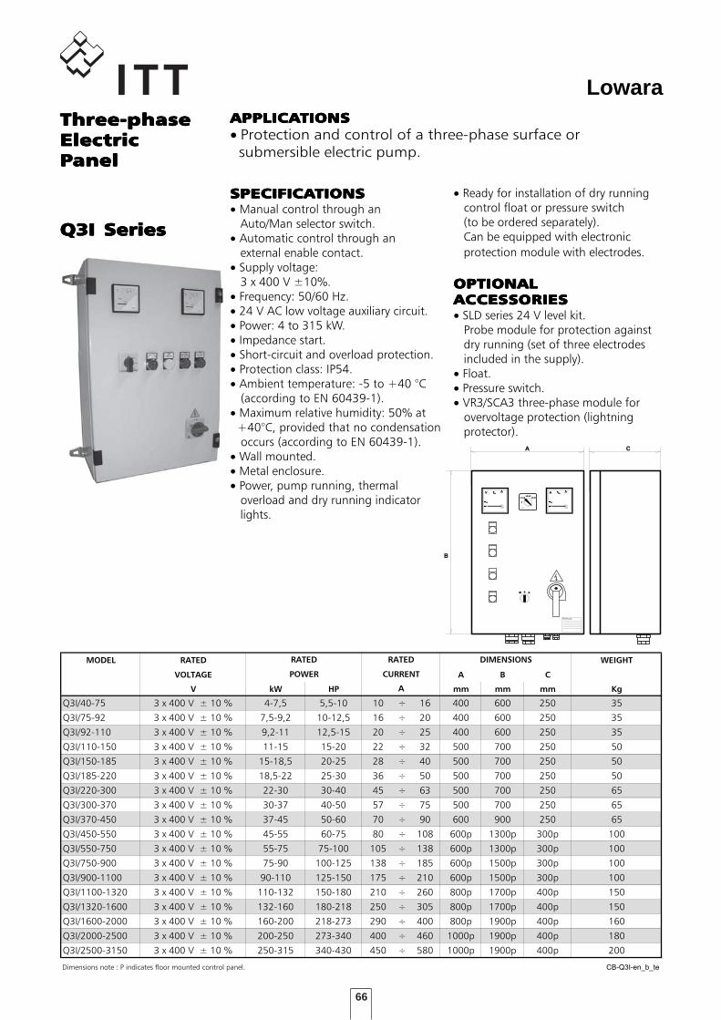
66
LowaraThree-phaseThree-phaseThree-phaseThree-phaseThree-phaseElectricElectricElectricElectricElectricPPPPPanelanelanelanelanel
Q3I SeriesQ3I SeriesQ3I SeriesQ3I SeriesQ3I Series
APPLICAAPPLICAAPPLICAAPPLICAAPPLICATIONSTIONSTIONSTIONSTIONS• Protection and control of a three-phase surface or submersible electric pump.
SERIE Q3I
MODEL RATED WEIGHT
VOLTAGE A B C
V kW HP mm mm mm Kg
Q3I/40-75 3 x 400 V ± 10 % 4-7,5 5,5-10 10 ÷ 16 400 600 250 35
Q3I/75-92 3 x 400 V ± 10 % 7,5-9,2 10-12,5 16 ÷ 20 400 600 250 35
Q3I/92-110 3 x 400 V ± 10 % 9,2-11 12,5-15 20 ÷ 25 400 600 250 35
Q3I/110-150 3 x 400 V ± 10 % 11-15 15-20 22 ÷ 32 500 700 250 50
Q3I/150-185 3 x 400 V ± 10 % 15-18,5 20-25 28 ÷ 40 500 700 250 50
Q3I/185-220 3 x 400 V ± 10 % 18,5-22 25-30 36 ÷ 50 500 700 250 50
Q3I/220-300 3 x 400 V ± 10 % 22-30 30-40 45 ÷ 63 500 700 250 65
Q3I/300-370 3 x 400 V ± 10 % 30-37 40-50 57 ÷ 75 500 700 250 65
Q3I/370-450 3 x 400 V ± 10 % 37-45 50-60 70 ÷ 90 600 900 250 65
Q3I/450-550 3 x 400 V ± 10 % 45-55 60-75 80 ÷ 108 600p 1300p 300p 100
Q3I/550-750 3 x 400 V ± 10 % 55-75 75-100 105 ÷ 138 600p 1300p 300p 100
Q3I/750-900 3 x 400 V ± 10 % 75-90 100-125 138 ÷ 185 600p 1500p 300p 100
Q3I/900-1100 3 x 400 V ± 10 % 90-110 125-150 175 ÷ 210 600p 1500p 300p 100
Q3I/1100-1320 3 x 400 V ± 10 % 110-132 150-180 210 ÷ 260 800p 1700p 400p 150
Q3I/1320-1600 3 x 400 V ± 10 % 132-160 180-218 250 ÷ 305 800p 1700p 400p 150
Q3I/1600-2000 3 x 400 V ± 10 % 160-200 218-273 290 ÷ 400 800p 1900p 400p 160
Q3I/2000-2500 3 x 400 V ± 10 % 200-250 273-340 400 ÷ 460 1000p 1900p 400p 180
Q3I/2500-3150 3 x 400 V ± 10 % 250-315 340-430 450 ÷ 580 1000p 1900p 400p 200
Dimensions note : P indicates floor mounted control panel. CB-Q3I-en_b_te
A
RATED
POWER
DIMENSIONSRATED
CURRENT
• Ready for installation of dry running control float or pressure switch (to be ordered separately). Can be equipped with electronic protection module with electrodes.
OPTIONALOPTIONALOPTIONALOPTIONALOPTIONALACCESACCESACCESACCESACCESSORIESSORIESSORIESSORIESSORIES• SLD series 24 V level kit. Probe module for protection against dry running (set of three electrodes included in the supply).• Float.• Pressure switch.• VR3/SCA3 three-phase module for overvoltage protection (lightning protector).
SPECIFICASPECIFICASPECIFICASPECIFICASPECIFICATIONSTIONSTIONSTIONSTIONS• Manual control through an Auto/Man selector switch.• Automatic control through an external enable contact.• Supply voltage: 3 x 400 V ±10%.• Frequency: 50/60 Hz.• 24 V AC low voltage auxiliary circuit.• Power: 4 to 315 kW.• Impedance start.• Short-circuit and overload protection.• Protection class: IP54.• Ambient temperature: -5 to +40 °C (according to EN 60439-1).• Maximum relative humidity: 50% at +40°C, provided that no condensation occurs (according to EN 60439-1).• Wall mounted.• Metal enclosure.• Power, pump running, thermal overload and dry running indicator lights.
0
200
150A
25
0
V 500
300
50 0
L1-L2
L2-L3
L3-L1
0M A
A
B
C
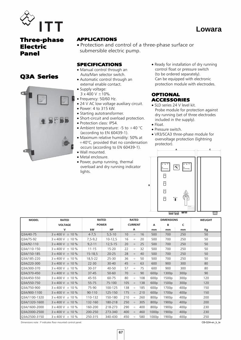
67
LowaraThree-phaseThree-phaseThree-phaseThree-phaseThree-phaseElectricElectricElectricElectricElectricPPPPPanelanelanelanelanel
Q3A SeriesQ3A SeriesQ3A SeriesQ3A SeriesQ3A Series
APPLICAAPPLICAAPPLICAAPPLICAAPPLICATIONSTIONSTIONSTIONSTIONS• Protection and control of a three-phase surface or submersible electric pump.
SERIE Q3A
MODEL RATED WEUGHT
VOLTAGE A B C
V kW HP mm mm mm Kg
Q3A/40-75 3 x 400 V ± 10 % 4-7,5 5,5-10 10 ÷ 16 500 700 250 50
Q3A/75-92 3 x 400 V ± 10 % 7,5-9,2 10-12,5 16 ÷ 20 500 700 250 50
Q3A/92-110 3 x 400 V ± 10 % 9,2-11 12,5-15 20 ÷ 25 500 700 250 50
Q3A/110-150 3 x 400 V ± 10 % 11-15 15-20 22 ÷ 32 500 700 250 50
Q3A/150-185 3 x 400 V ± 10 % 15-18,5 20-25 28 ÷ 40 500 700 250 50
Q3A/185-220 3 x 400 V ± 10 % 18,5-22 25-30 36 ÷ 50 500 700 250 50
Q3A/220-300 3 x 400 V ± 10 % 22-30 30-40 45 ÷ 63 600 900 300 80
Q3A/300-370 3 x 400 V ± 10 % 30-37 40-50 57 ÷ 75 600 900 300 80
Q3A/370-450 3 x 400 V ± 10 % 37-45 50-60 70 ÷ 90 600p 1300p 300p 90
Q3A/450-550 3 x 400 V ± 10 % 45-55 60-75 80 ÷ 108 600p 1500p 300p 120
Q3A/550-750 3 x 400 V ± 10 % 55-75 75-100 105 ÷ 138 600p 1500p 300p 120
Q3A/750-900 3 x 400 V ± 10 % 75-90 100-125 138 ÷ 185 600p 1700p 400p 150
Q3A/900-1100 3 x 400 V ± 10 % 90-110 125-150 175 ÷ 210 600p 1700p 400p 150
Q3A/1100-1320 3 x 400 V ± 10 % 110-132 150-180 210 ÷ 260 800p 1900p 400p 200
Q3A/1320-1600 3 x 400 V ± 10 % 132-160 180-218 250 ÷ 305 800p 1900p 400p 200
Q3A/1600-2000 3 x 400 V ± 10 % 160-200 218-273 290 ÷ 400 800p 1900p 400p 230
Q3A/2000-2500 3 x 400 V ± 10 % 200-250 273-340 400 ÷ 460 1000p 1900p 400p 230
Q3A/2500-3150 3 x 400 V ± 10 % 250-315 340-430 450 ÷ 580 1000p 1900p 400p 250
Dimensions note : P indicates floor mounted control panel. CB-Q3A-en_b_te
A
RATED
POWER
DIMENSIONSRATED
CURRENT
• Ready for installation of dry running control float or pressure switch (to be ordered separately). Can be equipped with electronic protection module with electrodes.
OPTIONALOPTIONALOPTIONALOPTIONALOPTIONALACCESACCESACCESACCESACCESSORIESSORIESSORIESSORIESSORIES• SLD series 24 V level kit. Probe module for protection against dry running (set of three electrodes included in the supply).• Float.• Pressure switch.• VR3/SCA3 three-phase module for overvoltage protection (lightning protector).
SPECIFICASPECIFICASPECIFICASPECIFICASPECIFICATIONSTIONSTIONSTIONSTIONS• Manual control through an Auto/Man selector switch.• Automatic control through an external enable contact.• Supply voltage: 3 x 400 V ±10%.• Frequency: 50/60 Hz.• 24 V AC low voltage auxiliary circuit.• Power: 4 to 315 kW.• Starting autotransformer.• Short-circuit and overload protection.• Protection class: IP54.• Ambient temperature: -5 to +40 °C (according to EN 60439-1).• Maximum relative humidity: 50% at +40°C, provided that no condensation occurs (according to EN 60439-1).• Wall mounted.• Metal enclosure.• Power, pump running, thermal overload and dry running indicator lights.
0
200
150A
25
0
V 500
300
50 0
L1-L2
L2-L3
L3-L1
0M A
A
B
C

68
LowaraThree-phaseThree-phaseThree-phaseThree-phaseThree-phaseElectricElectricElectricElectricElectricPPPPPanelanelanelanelanel
Q3SF SeriesQ3SF SeriesQ3SF SeriesQ3SF SeriesQ3SF Series
APPLICAAPPLICAAPPLICAAPPLICAAPPLICATIONSTIONSTIONSTIONSTIONS• Protection and control of a three-phase surface or submersible electric pump.
SERIE Q3SF
MODEL RATED WEIGHT
VOLTAGE A B C
V kW HP mm mm mm Kg
Q3SF 75 3 x 400 V ± 10 % 5,5 - 7,5 7,5 -10 8,5 ÷ 17 400 600 250 35
Q3SF 150 3 x 400 V ± 10 % 9,2 - 15 12,5 - 20 15 ÷ 30 500 700 250 40
Q3SF 220 3 x 400 V ± 10 % 18,5 - 22 25 - 30 28 ÷ 45 500 700 250 40
Q3SF 300 3 x 400 V ± 10 % 30 40 42 ÷ 60 600 900 300 90
Q3SF 370 3 x 400 V ± 10 % 37 50 55 ÷ 75 600 900 300 90
Q3SF 450 3 x 400 V ± 10 % 45 60 70 ÷ 85 600 900 300 90
Q3SF 550 3 x 400 V ± 10 % 55 75 80 ÷ 110 600 900 300 90
Q3SF 590 3 x 400 V ± 10 % 59 80 105 ÷ 125 600 900 300 90
Q3SF 750 3 x 400 V ± 10 % 75 100 120 ÷ 142 600p 1700p 400p 120
Q3SF 900 3 x 400 V ± 10 % 90 125 135 ÷ 190 600p 1700p 400p 120
Q3SF 1100 3 x 400 V ± 10 % 110 150 185 ÷ 245 600p 1700p 400p 120
Dimensions note : P indicates floor mounted control panel. CB-Q3SF-en_b_te
A
RATED
POWER
DIMENSIONSRATED
CURRENT
Protections against phase failure / phase sequence / frequency out of limits on power supply line. Low-voltage protection on auxiliary circuits. Protection against starter overtemperature / overload / malfunction. Protection against overload / locked rotor / current asymmetry on motor side. Short-circuit protection on inputs and outputs. RS232 interface for remote control and RS485 for use of remote keypanel. Incorporated by-pass contactor.
OPTIONALOPTIONALOPTIONALOPTIONALOPTIONALACCESACCESACCESACCESACCESSORIESSORIESSORIESSORIESSORIES• SLD series 24 V level kit. Probe module for protection against dry running (set of three electrodes included in the supply).• Float.• Pressure switch.• VR3/SCA3 three-phase module for overvoltage protection (lightning protector).
SPECIFICASPECIFICASPECIFICASPECIFICASPECIFICATIONSTIONSTIONSTIONSTIONS• Manual control through an Auto/Man selector switch.• Automatic control through an external enable contact.• Supply voltage: 3 x 400 V ±10%.• Frequency: 50/60 Hz.• 24 V AC low voltage auxiliary circuit.• Power: 5,5 to 110 kW.• Softstart with torque control.• Protection class: IP54.• Ambient temperature: -5 to +40 °C (according to EN 60439-1).• Maximum relative humidity: 50% at +40°C, provided that no condensation occurs (according to EN 60439-1).• Wall mounted.• Metal enclosure.• Dry running indicator light.• Power - pump running - malfunction LEDs on starter keypanel.• ON/OFF selector switch for activation of by-pass contactor.• Ready for installation of dry running control float or pressure switch (to be ordered separately). Can be equipped with electronic protection module with electrodes.
STSTSTSTSTAAAAATIC STTIC STTIC STTIC STTIC STARTERARTERARTERARTERARTERCHARACTERISTICCHARACTERISTICCHARACTERISTICCHARACTERISTICCHARACTERISTICSSSSS• Static starter for gradual start-up/ shutdown, featuring: keypanel with liquid crystal display showing voltage, absorbed current, cos ϕ, operating hours, number of starts, last twenty messages on system status (events / alarms).
0M A
A
B
C
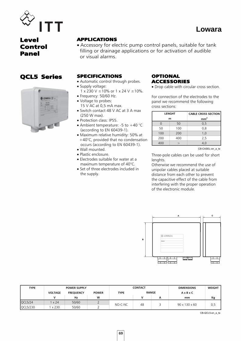
69
Lowara
For connection of the electrodes to thepanel we recommend the followingcross sections:
Three-pole cables can be used for shortlenghts.Otherwise we recommend the use ofunipolar cables placed at suitabledistance from each other to preventthe capacitive effect of the cable frominterfering with the proper operationof the electronic module.
LevelLevelLevelLevelLevelControlControlControlControlControlPPPPPanelanelanelanelanel
QCL5 SeriesQCL5 SeriesQCL5 SeriesQCL5 SeriesQCL5 Series
APPLICAAPPLICAAPPLICAAPPLICAAPPLICATIONSTIONSTIONSTIONSTIONS• Accessory for electric pump control panels, suitable for tank filling or drainage applications or for activation of audible or visual alarms.
SERIE QCL5
TYPE POWER SUPPLY DIMENSIONS WEIGHT
VOLTAGE FREQUENCY POWER TYPE A x B x C
V Hz W V A mm Kg
QCL5/24 1 x 24 50/60 2
QCL5/230 1 x 230 50/60 2
CB-QCL5-en_a_te
CONTACT
0,5
RANGE
90 x 130 x 60NO-C-NC 48 3
OPTIONALOPTIONALOPTIONALOPTIONALOPTIONALACCESACCESACCESACCESACCESSORIESSORIESSORIESSORIESSORIES• Drop cable with circular cross section.
SPECIFICASPECIFICASPECIFICASPECIFICASPECIFICATIONSTIONSTIONSTIONSTIONS• Automatic control through probes.• Supply voltage: 1 x 230 V ±10% or 1 x 24 V ±10%.• Frequency: 50/60 Hz.• Voltage to probes: 15 V AC at 0,5 mA max.• Switch contact 48 V AC at 3 A max (250 W max).• Protection class: IP55.• Ambient temperature: -5 to +40 °C (according to EN 60439-1).• Maximum relative humidity: 50% at +40°C, provided that no condensation occurs (according to EN 60439-1).• Wall mounted.• Plastic enclosure.• Electrodes suitable for water at a maximum temperature of 40°C.• Set of three electrodes included in the supply.
TABELLA CAVI
CABLE CROSS SECTION
mm2
0 50 0,5
50 100 0,8
100 200 1,0
200 400 2,5
400 > 4,0
CB-CASEL-en_a_te
LENGHT
m
Control box
A
B
C
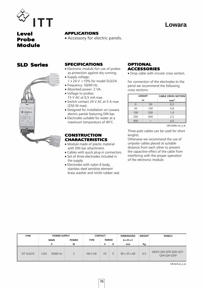
70
Lowara
For connection of the electrodes to thepanel we recommend the followingcross sections:
Three-pole cables can be used for shortlenghts.Otherwise we recommend the use ofunipolar cables placed at suitabledistance from each other to preventthe capacitive effect of the cable frominterfering with the proper operationof the electronic module.
LevelLevelLevelLevelLevelProbeProbeProbeProbeProbeModuleModuleModuleModuleModule
SLD SeriesSLD SeriesSLD SeriesSLD SeriesSLD Series
APPLICAAPPLICAAPPLICAAPPLICAAPPLICATIONSTIONSTIONSTIONSTIONS• Accessory for electric panels.
SERIE SLD
TYPE DIMENSIONS WEIGHT PANELS
MAIN POWER TYPE A x B x C
V W V A mm Kg
KIT SLD/24 1x24 50/60 Hz 2 N0-C-NC 24 5 90 x 35 x 60 0,5QMCS-QM-QTD-Q3D-Q3Y-
Q3A-Q3I-Q3SF
CB-SLD-en_a_te
POWER SUPPLY CONTACT
RANGE
OPTIONALOPTIONALOPTIONALOPTIONALOPTIONALACCESACCESACCESACCESACCESSORIESSORIESSORIESSORIESSORIES• Drop cable with circular cross section.
SPECIFICASPECIFICASPECIFICASPECIFICASPECIFICATIONSTIONSTIONSTIONSTIONS• Electronic module forr use of probes as protection against dry running.• Supply voltage: 1 x 24 V ±10% for model SLD/24.• Frequency: 50/60 Hz.• Absorbed power: 2 VA.• Voltage to probes: 15 V AC at 0,5 mA max.• Switch contact 24 V AC at 5 A max (250 W max).• Designed for installation on Lowara electric panels featuring DIN bar.• Electrodes suitable for water at a maximum temperature of 40°C.
TABELLA CAVI
CABLE CROSS SECTION
mm2
0 50 0,5
50 100 0,8
100 200 1,0
200 400 2,5
400 > 4,0
CB-CASEL-en_a_te
LENGHT
m
CONSTRUCTIONCONSTRUCTIONCONSTRUCTIONCONSTRUCTIONCONSTRUCTIONCHARACTERISTICCHARACTERISTICCHARACTERISTICCHARACTERISTICCHARACTERISTICSSSSS• Module made of plastic material with DIN bar attachment.• Cables with quick plug-in connectors.• Set of three electrodes included in the supply.• Electrodes with nylon 6 body, stainless steel sensitive element brass washer and nitrile rubber seal.
71
LowaraLightningLightningLightningLightningLightningProtectionProtectionProtectionProtectionProtection
DPF SeriesDPF SeriesDPF SeriesDPF SeriesDPF Series
APPLICAAPPLICAAPPLICAAPPLICAAPPLICATIONSTIONSTIONSTIONSTIONS• Accessory for electric panels.
SERIE VR
TYPE VOLTAGE PANELS
V
DPF 1 x 220-240 50/60 Hz QSM - QMC - QMCS - QPC
KIT VR1 1 x 220-230 50/60 Hz QM - QDRM - QDRM2
KIT VR3 3 x 400 50/60 Hz QTD - QDR - QDR2 - Q3D
KIT SCA 3 3 x 400 50/60 Hz Q3Y-Q3A-Q3I-Q3SF-Q3D
CB-VR-en_b_te
SPECIFICASPECIFICASPECIFICASPECIFICASPECIFICATIONSTIONSTIONSTIONSTIONS• Varistors for overvoltage protection of three-phase lines.• To be connected between the phases (VR3 model).• Operating voltage: 460 V AC.• Maximum varistor voltage: 750 V with 100 A peak current.• Designed for installation on Lowara electric panels featuring DIN bar.
SPECIFICASPECIFICASPECIFICASPECIFICASPECIFICATIONSTIONSTIONSTIONSTIONS• Lightning arresters for overvoltage protection of three-phase lines. To be connected between the phases and the heart conductor,• Operating voltage: 500 V AC.• Maximum varistor voltage: 2,5 kW with 40 kA peak current.• Designed for installation on Lowara electric panels featuring DIN bar.
SPECIFICASPECIFICASPECIFICASPECIFICASPECIFICATIONSTIONSTIONSTIONSTIONS• Varistor for overvoltage protection of single-phase lines. To be connected between the phase and neutral conductor.• Operating voltage: 460 V AC.• Maximum varistor voltage: 750 V with 100 A peak current.
VR SeriesVR SeriesVR SeriesVR SeriesVR Series
SCA3 SeriesSCA3 SeriesSCA3 SeriesSCA3 SeriesSCA3 Series

72
Lowara
73
Lowara
TECHNICALTECHNICALTECHNICALTECHNICALTECHNICALAPPENDIXAPPENDIXAPPENDIXAPPENDIXAPPENDIX
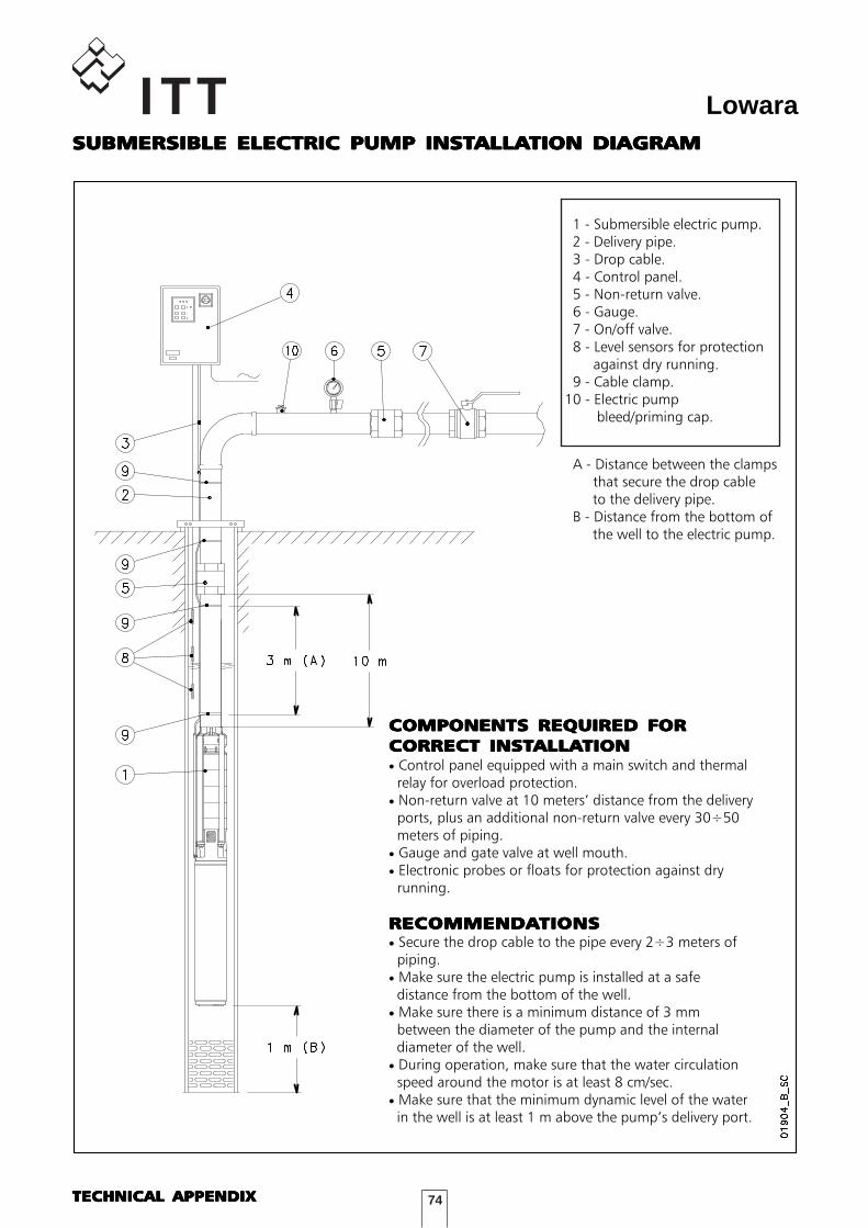
74
LowaraSUBMERSIBLE ELECTRIC PUMP INSTSUBMERSIBLE ELECTRIC PUMP INSTSUBMERSIBLE ELECTRIC PUMP INSTSUBMERSIBLE ELECTRIC PUMP INSTSUBMERSIBLE ELECTRIC PUMP INSTALLAALLAALLAALLAALLATION DIAGRAMTION DIAGRAMTION DIAGRAMTION DIAGRAMTION DIAGRAM
1 - Submersible electric pump. 2 - Delivery pipe. 3 - Drop cable. 4 - Control panel. 5 - Non-return valve. 6 - Gauge. 7 - On/off valve. 8 - Level sensors for protection against dry running. 9 - Cable clamp.10 - Electric pump bleed/priming cap.
A - Distance between the clamps that secure the drop cable to the delivery pipe. B - Distance from the bottom of the well to the electric pump.
COMPONENTS REQUIRED FORCOMPONENTS REQUIRED FORCOMPONENTS REQUIRED FORCOMPONENTS REQUIRED FORCOMPONENTS REQUIRED FORCORRECT INSTCORRECT INSTCORRECT INSTCORRECT INSTCORRECT INSTALLAALLAALLAALLAALLATIONTIONTIONTIONTION• Control panel equipped with a main switch and thermal relay for overload protection.• Non-return valve at 10 meters’ distance from the delivery ports, plus an additional non-return valve every 30÷50 meters of piping.• Gauge and gate valve at well mouth.• Electronic probes or floats for protection against dry running.
RECOMMENDARECOMMENDARECOMMENDARECOMMENDARECOMMENDATIONSTIONSTIONSTIONSTIONS• Secure the drop cable to the pipe every 2÷3 meters of piping.• Make sure the electric pump is installed at a safe distance from the bottom of the well.• Make sure there is a minimum distance of 3 mm between the diameter of the pump and the internal diameter of the well.• During operation, make sure that the water circulation speed around the motor is at least 8 cm/sec.• Make sure that the minimum dynamic level of the water in the well is at least 1 m above the pump’s delivery port.
TECHNICAL APPENDIXTECHNICAL APPENDIXTECHNICAL APPENDIXTECHNICAL APPENDIXTECHNICAL APPENDIX
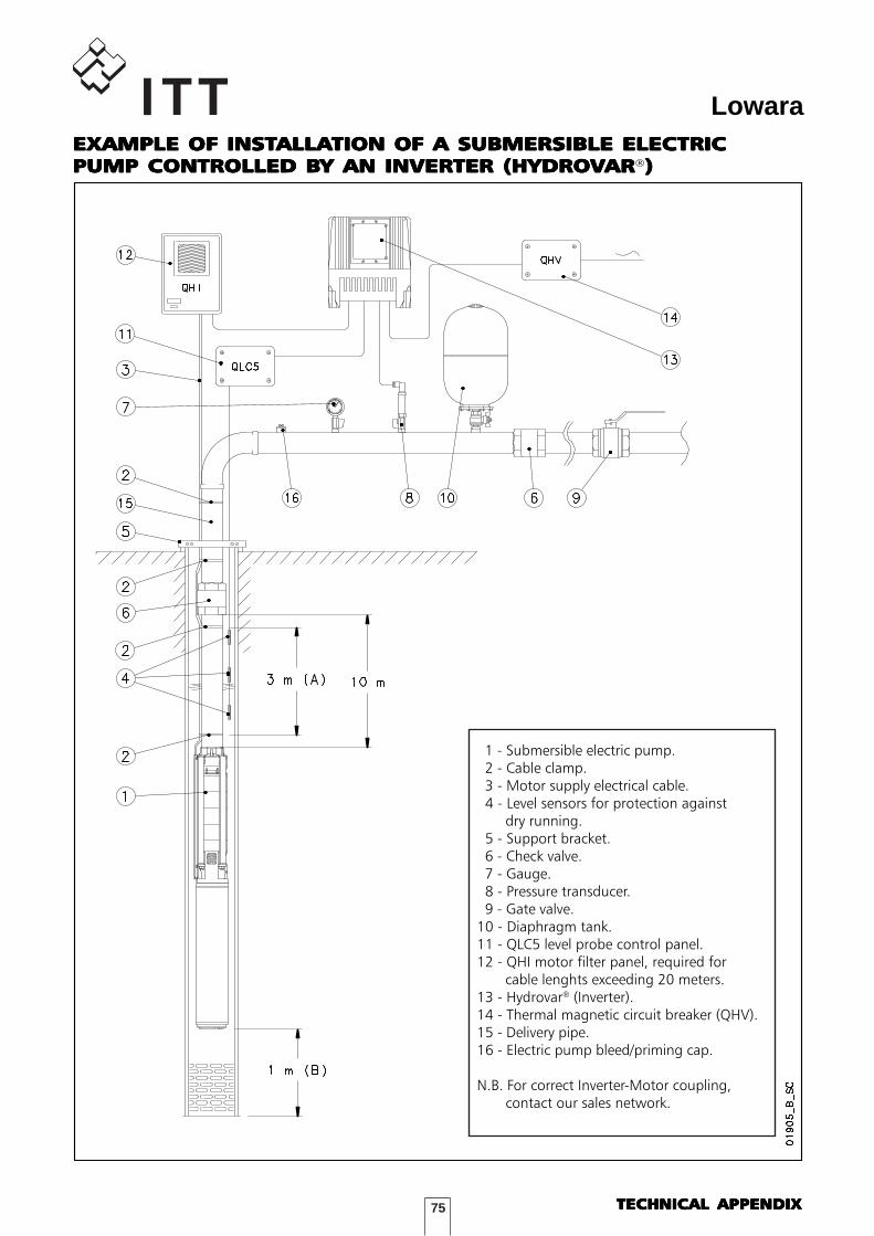
75
Lowara
TECHNICAL APPENDIXTECHNICAL APPENDIXTECHNICAL APPENDIXTECHNICAL APPENDIXTECHNICAL APPENDIX
EXAMPLE OF INSTEXAMPLE OF INSTEXAMPLE OF INSTEXAMPLE OF INSTEXAMPLE OF INSTALLAALLAALLAALLAALLATION OF A SUBMERSIBLE ELECTRICTION OF A SUBMERSIBLE ELECTRICTION OF A SUBMERSIBLE ELECTRICTION OF A SUBMERSIBLE ELECTRICTION OF A SUBMERSIBLE ELECTRICPUMP CONTROLLED BPUMP CONTROLLED BPUMP CONTROLLED BPUMP CONTROLLED BPUMP CONTROLLED BY AN INVERTER (HYDROY AN INVERTER (HYDROY AN INVERTER (HYDROY AN INVERTER (HYDROY AN INVERTER (HYDROVVVVVARARARARAR®)))))
1 - Submersible electric pump. 2 - Cable clamp. 3 - Motor supply electrical cable. 4 - Level sensors for protection against dry running. 5 - Support bracket. 6 - Check valve. 7 - Gauge. 8 - Pressure transducer. 9 - Gate valve.10 - Diaphragm tank.11 - QLC5 level probe control panel.12 - QHI motor filter panel, required for cable lenghts exceeding 20 meters.13 - Hydrovar® (Inverter).14 - Thermal magnetic circuit breaker (QHV).15 - Delivery pipe.16 - Electric pump bleed/priming cap.
N.B. For correct Inverter-Motor coupling, contact our sales network.
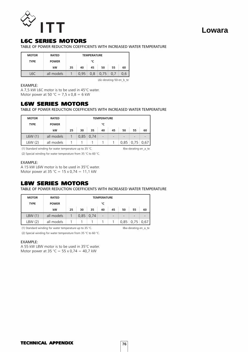
76
LowaraL6C SERIES MOTORS
MOTOR RATED TEMPERATURE
TYPE POWER °C
kW 35 40 45 50 55 60
L6C all models 1 0,95 0,8 0,75 0,7 0,6
L6c-derating-50-en_b_te
L6C SERIES MOTORSL6C SERIES MOTORSL6C SERIES MOTORSL6C SERIES MOTORSL6C SERIES MOTORSTABLE OF POWER REDUCTION COEFFICIENTS WITH INCREASED WATER TEMPERATURE
EXAMPLE:A 7,5 kW L6C motor is to be used in 45°C water.Motor power at 50 °C = 7,5 x 0,8 = 6 kW
L6W SERIES MOTORS
MOTOR RATED TEMPERATURE
TYPE POWER °C
kW 25 30 35 40 45 50 55 60
L6W (1) all models 1 0,85 0,74 - - - - -
L6W (2) all models 1 1 1 1 1 0,85 0,75 0,67
(1) Standard winding for water temperature up to 35 °C. l6w-derating-en_a_te
(2) Special winding for water temperature from 35 °C to 60 °C.
L6W SERIES MOTORSL6W SERIES MOTORSL6W SERIES MOTORSL6W SERIES MOTORSL6W SERIES MOTORSTABLE OF POWER REDUCTION COEFFICIENTS WITH INCREASED WATER TEMPERATURE
EXAMPLE:A 15 kW L6W motor is to be used in 35°C water.Motor power at 35 °C = 15 x 0,74 = 11,1 kW
L8W SERIES MOTORS
MOTOR RATED TEMPERATURE
TYPE POWER °C
kW 25 30 35 40 45 50 55 60
L8W (1) all models 1 0,85 0,74 - - - - -
L8W (2) all models 1 1 1 1 1 0,85 0,75 0,67
(1) Standard winding for water temperature up to 35 °C. l8w-derating-en_a_te
(2) Special winding for water temperature from 35 °C to 60 °C.
L8W SERIES MOTORSL8W SERIES MOTORSL8W SERIES MOTORSL8W SERIES MOTORSL8W SERIES MOTORSTABLE OF POWER REDUCTION COEFFICIENTS WITH INCREASED WATER TEMPERATURE
EXAMPLE:A 55 kW L8W motor is to be used in 35°C water.Motor power at 35 °C = 55 x 0,74 = 40,7 kW
TECHNICAL APPENDIXTECHNICAL APPENDIXTECHNICAL APPENDIXTECHNICAL APPENDIXTECHNICAL APPENDIX
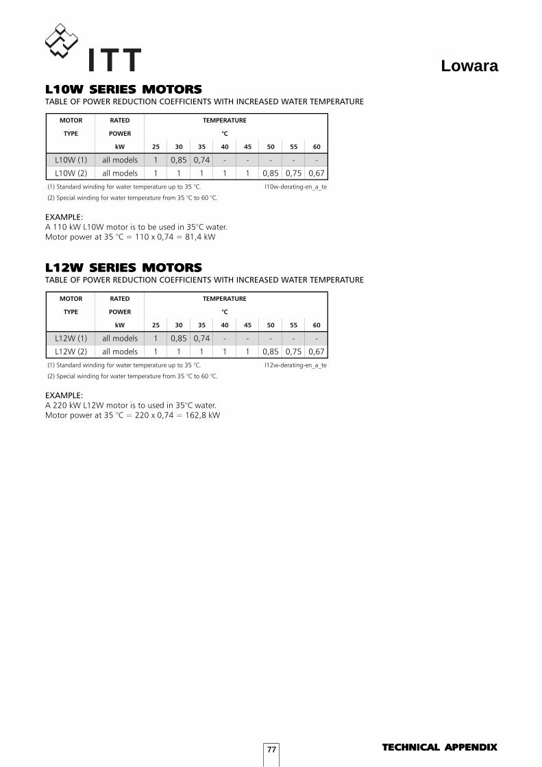
77
Lowara
EXAMPLE:A 110 kW L10W motor is to be used in 35°C water.Motor power at 35 °C = 110 x 0,74 = 81,4 kW
L10W SERIES MOTORSL10W SERIES MOTORSL10W SERIES MOTORSL10W SERIES MOTORSL10W SERIES MOTORSTABLE OF POWER REDUCTION COEFFICIENTS WITH INCREASED WATER TEMPERATURE
L10W SERIES MOTORS
MOTOR RATED TEMPERATURE
TYPE POWER °C
kW 25 30 35 40 45 50 55 60
L10W (1) all models 1 0,85 0,74 - - - - -
L10W (2) all models 1 1 1 1 1 0,85 0,75 0,67
(1) Standard winding for water temperature up to 35 °C. l10w-derating-en_a_te
(2) Special winding for water temperature from 35 °C to 60 °C.
L12W SERIES MOTORSL12W SERIES MOTORSL12W SERIES MOTORSL12W SERIES MOTORSL12W SERIES MOTORSTABLE OF POWER REDUCTION COEFFICIENTS WITH INCREASED WATER TEMPERATURE
EXAMPLE:A 220 kW L12W motor is to used in 35°C water.Motor power at 35 °C = 220 x 0,74 = 162,8 kW
L12W SERIES MOTORS
MOTOR RATED TEMPERATURE
TYPE POWER °C
kW 25 30 35 40 45 50 55 60
L12W (1) all models 1 0,85 0,74 - - - - -
L12W (2) all models 1 1 1 1 1 0,85 0,75 0,67
(1) Standard winding for water temperature up to 35 °C. l12w-derating-en_a_te
(2) Special winding for water temperature from 35 °C to 60 °C.
TECHNICAL APPENDIXTECHNICAL APPENDIXTECHNICAL APPENDIXTECHNICAL APPENDIXTECHNICAL APPENDIX
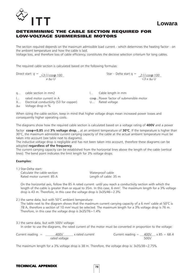
78
LowaraDETERMINING THE CABLE SECTION REQUIRED FORLOW-VOLTAGE SUBMERSIBLE MOTORS
The section required depends on the maximum admissible load current - which determines the heating factor - onthe ambient temperature and how the cable is laid.Voltage loss, and therefore loss of cable efficiency, constitutes the decisive selection criterium for long cables.
The required cable section is calculated based on the following formulas:
Direct start: q = Star – Delta start q =
q... cable section in mm2 l... Cable length in mm
l... rated motor current in A cos�... Power factor of submersible motorX... Electrical conductivity (53 for copper) U... Rated voltage∆u Voltage drop in %
When sizing the cable section, keep in mind that higher voltage drops mean increased power losses andconsequently higher operating costs.
The diagrams show how the required cable section is calculated based on a voltage rating of 400V and a power
factor cos�=0,85 and 3% voltage drop, , at an ambient temperature of 30°C. If the temperature is higher than30°C, the maximum admissible current carrying capacity of the cable at the actual ambient temperature must betaken into account (see table next to diagrams).The inductive voltage drop is negligible and has not been taken into account, therefore these diagrams can beadopted regardless of the frequency.The current carrying capacity can be established from the horizontal lines above the length of the cable (verticallines). The bend point indicates the limit length for 3% voltage drops.
Examples:
1.) Star-Delta start:Calculate the cable section Waterproof cableRated motor current: 85 A Length of cable: 35 m
On the horizontal axis, follow the 85 A rated current until you reach a conductivity section with which thelength of the cable is greater than or equal to 35m. In this case, 6 mm2. The maximum length for a 3% voltagedrop is 43 m. Therefore, in this case the voltage drop is 3x35/46=2.3%
2.) the same data, but with 50°C ambient temperature:The table next to the diagram shows that the maximum current carrying capacity of a 6 mm2 cable at 50°C is78 A, therefore a section of 10 mm2 must be selected. The maximum length for a 3% voltage drop is 76 m.Therefore, in this case the voltage drop is 3x35/76=1.4%
3.) the same data, but with 500V voltage:In order to use the diagrams, the rated current of the motor must be converted in proportion to the voltage:
Current reading = 400V x rated current Current reading = 400V x 85 = 68 Arated voltage 500V
The maximum length for a 3% voltage drop is 38 m. Therefore, the voltage drop is: 3x35/38=2.75%
√3·l·l·cos�·100 x·∆u·U
2·l·l·cos�·100 √3·x·∆u·U
TECHNICAL APPENDIXTECHNICAL APPENDIXTECHNICAL APPENDIXTECHNICAL APPENDIXTECHNICAL APPENDIX
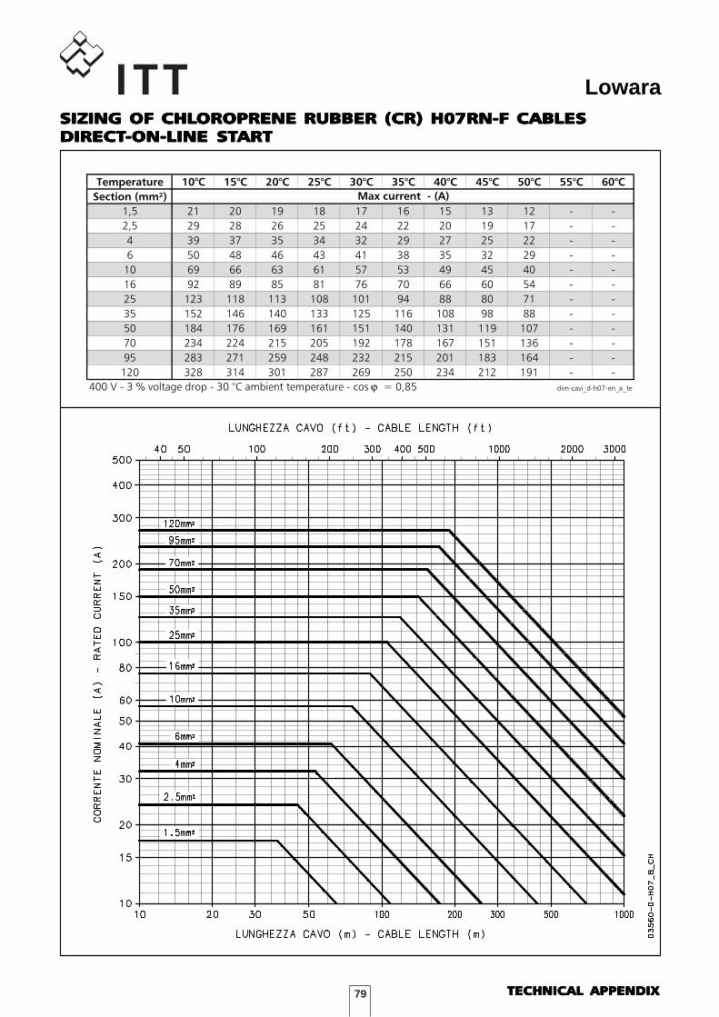
79
LowaraSIZING OF CHLSIZING OF CHLSIZING OF CHLSIZING OF CHLSIZING OF CHLOROPRENE RUBBER (CR) H07RN-F CABLESOROPRENE RUBBER (CR) H07RN-F CABLESOROPRENE RUBBER (CR) H07RN-F CABLESOROPRENE RUBBER (CR) H07RN-F CABLESOROPRENE RUBBER (CR) H07RN-F CABLESDIRECTDIRECTDIRECTDIRECTDIRECT-ON-LINE ST-ON-LINE ST-ON-LINE ST-ON-LINE ST-ON-LINE STARTARTARTARTART
DIMENSIONAMENTO CAVI in H07RN-F - AVVIAMENTO DIRETTO
Temperature 10°C 15°C 20°C 25°C 30°C 35°C 40°C 45°C 50°C 55°C 60°C
Section (mm²)
1,5 21 20 19 18 17 16 15 13 12 - -
2,5 29 28 26 25 24 22 20 19 17 - -
4 39 37 35 34 32 29 27 25 22 - -
6 50 48 46 43 41 38 35 32 29 - -
10 69 66 63 61 57 53 49 45 40 - -
16 92 89 85 81 76 70 66 60 54 - -
25 123 118 113 108 101 94 88 80 71 - -
35 152 146 140 133 125 116 108 98 88 - -
50 184 176 169 161 151 140 131 119 107 - -
70 234 224 215 205 192 178 167 151 136 - -
95 283 271 259 248 232 215 201 183 164 - -
120 328 314 301 287 269 250 234 212 191 - -
400 V - 3 % voltage drop - 30 °C ambient temperature - cos ϕ = 0,85 dim-cavi_d-h07-en_a_te
Max current - (A)
TECHNICAL APPENDIXTECHNICAL APPENDIXTECHNICAL APPENDIXTECHNICAL APPENDIXTECHNICAL APPENDIX
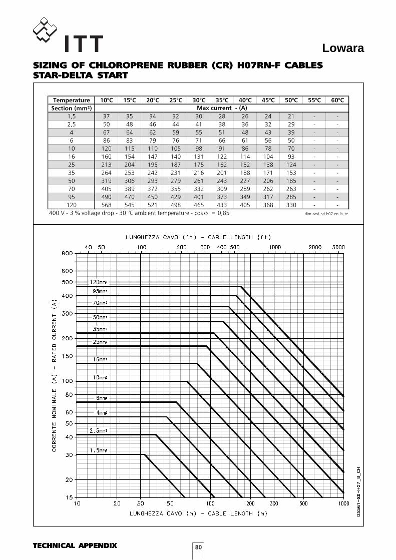
80
LowaraSIZING OF CHLSIZING OF CHLSIZING OF CHLSIZING OF CHLSIZING OF CHLOROPRENE RUBBER (CR) H07RN-F CABLESOROPRENE RUBBER (CR) H07RN-F CABLESOROPRENE RUBBER (CR) H07RN-F CABLESOROPRENE RUBBER (CR) H07RN-F CABLESOROPRENE RUBBER (CR) H07RN-F CABLESSTSTSTSTSTAR-DELAR-DELAR-DELAR-DELAR-DELTTTTTA STA STA STA STA STARTARTARTARTART
DIMENSIONAMENTO CAVI in H07RN-F - AVVIAMENTO STELLA-TRIANGOLO
Temperature 10°C 15°C 20°C 25°C 30°C 35°C 40°C 45°C 50°C 55°C 60°C
Section (mm²)
1,5 37 35 34 32 30 28 26 24 21 - -
2,5 50 48 46 44 41 38 36 32 29 - -
4 67 64 62 59 55 51 48 43 39 - -
6 86 83 79 76 71 66 61 56 50 - -
10 120 115 110 105 98 91 86 78 70 - -
16 160 154 147 140 131 122 114 104 93 - -
25 213 204 195 187 175 162 152 138 124 - -
35 264 253 242 231 216 201 188 171 153 - -
50 319 306 293 279 261 243 227 206 185 - -
70 405 389 372 355 332 309 289 262 263 - -
95 490 470 450 429 401 373 349 317 285 - -
120 568 545 521 498 465 433 405 368 330 - -
400 V - 3 % voltage drop - 30 °C ambient temperature - cos ϕ = 0,85 dim-cavi_sd-h07-en_b_te
Max current - (A)
TECHNICAL APPENDIXTECHNICAL APPENDIXTECHNICAL APPENDIXTECHNICAL APPENDIXTECHNICAL APPENDIX
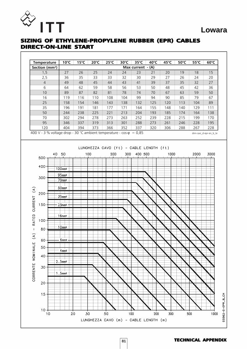
81
LowaraSIZING OF ETHYLENE-PROPYLENE RUBBER (EPR) CABLESSIZING OF ETHYLENE-PROPYLENE RUBBER (EPR) CABLESSIZING OF ETHYLENE-PROPYLENE RUBBER (EPR) CABLESSIZING OF ETHYLENE-PROPYLENE RUBBER (EPR) CABLESSIZING OF ETHYLENE-PROPYLENE RUBBER (EPR) CABLESDIRECTDIRECTDIRECTDIRECTDIRECT-ON-LINE ST-ON-LINE ST-ON-LINE ST-ON-LINE ST-ON-LINE STARTARTARTARTART
DIMENSIONAMENTO CAVI in ETILENPROPILENE (EPR) - AVVIAMENTO DIRE
Temperature 10°C 15°C 20°C 25°C 30°C 35°C 40°C 45°C 50°C 55°C 60°C
Section (mm²)
1,5 27 26 25 24 24 23 21 20 19 18 15
2,5 36 35 33 33 32 30 29 27 26 24 20
4 49 48 45 44 43 41 39 37 35 32 27
6 64 62 59 58 56 53 50 48 45 42 36
10 89 87 82 81 78 74 70 67 63 59 50
16 119 116 110 108 104 99 94 90 85 79 67
25 158 154 146 143 138 132 125 120 113 104 89
35 196 191 181 177 171 164 155 148 140 129 111
50 244 238 225 221 213 204 193 185 174 164 138
70 302 294 278 273 263 252 239 228 215 199 170
95 346 337 319 313 301 288 273 261 246 228 195
120 404 394 373 366 352 337 320 306 288 267 228
400 V - 3 % voltage drop - 30 °C ambient temperature - cos ϕ = 0,85 dim-cavi_d-epr-en_b_te
Max current - (A)
TECHNICAL APPENDIXTECHNICAL APPENDIXTECHNICAL APPENDIXTECHNICAL APPENDIXTECHNICAL APPENDIX
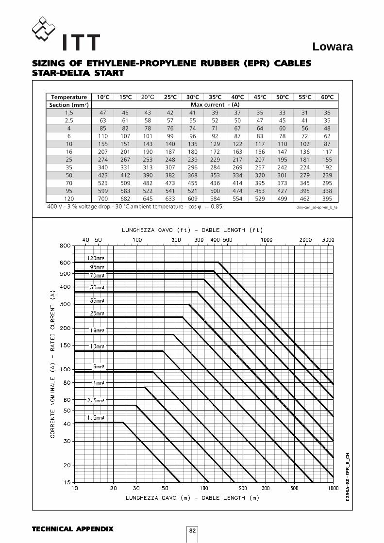
82
LowaraSIZING OF ETHYLENE-PROPYLENE RUBBER (EPR) CABLESSIZING OF ETHYLENE-PROPYLENE RUBBER (EPR) CABLESSIZING OF ETHYLENE-PROPYLENE RUBBER (EPR) CABLESSIZING OF ETHYLENE-PROPYLENE RUBBER (EPR) CABLESSIZING OF ETHYLENE-PROPYLENE RUBBER (EPR) CABLESSTSTSTSTSTAR-DELAR-DELAR-DELAR-DELAR-DELTTTTTA STA STA STA STA STARTARTARTARTART
DIMENSIONAMENTO CAVI in ETILENPROPILENE (EPR) - AVVIAMENTO STEL
Temperature 10°C 15°C 20°C 25°C 30°C 35°C 40°C 45°C 50°C 55°C 60°C
Section (mm²)
1,5 47 45 43 42 41 39 37 35 33 31 36
2,5 63 61 58 57 55 52 50 47 45 41 35
4 85 82 78 76 74 71 67 64 60 56 48
6 110 107 101 99 96 92 87 83 78 72 62
10 155 151 143 140 135 129 122 117 110 102 87
16 207 201 190 187 180 172 163 156 147 136 117
25 274 267 253 248 239 229 217 207 195 181 155
35 340 331 313 307 296 284 269 257 242 224 192
50 423 412 390 382 368 353 334 320 301 279 239
70 523 509 482 473 455 436 414 395 373 345 295
95 599 583 522 541 521 500 474 453 427 395 338
120 700 682 645 633 609 584 554 529 499 462 395
400 V - 3 % voltage drop - 30 °C ambient temperature - cos ϕ = 0,85 dim-cavi_sd-epr-en_b_te
Max current - (A)
TECHNICAL APPENDIXTECHNICAL APPENDIXTECHNICAL APPENDIXTECHNICAL APPENDIXTECHNICAL APPENDIX
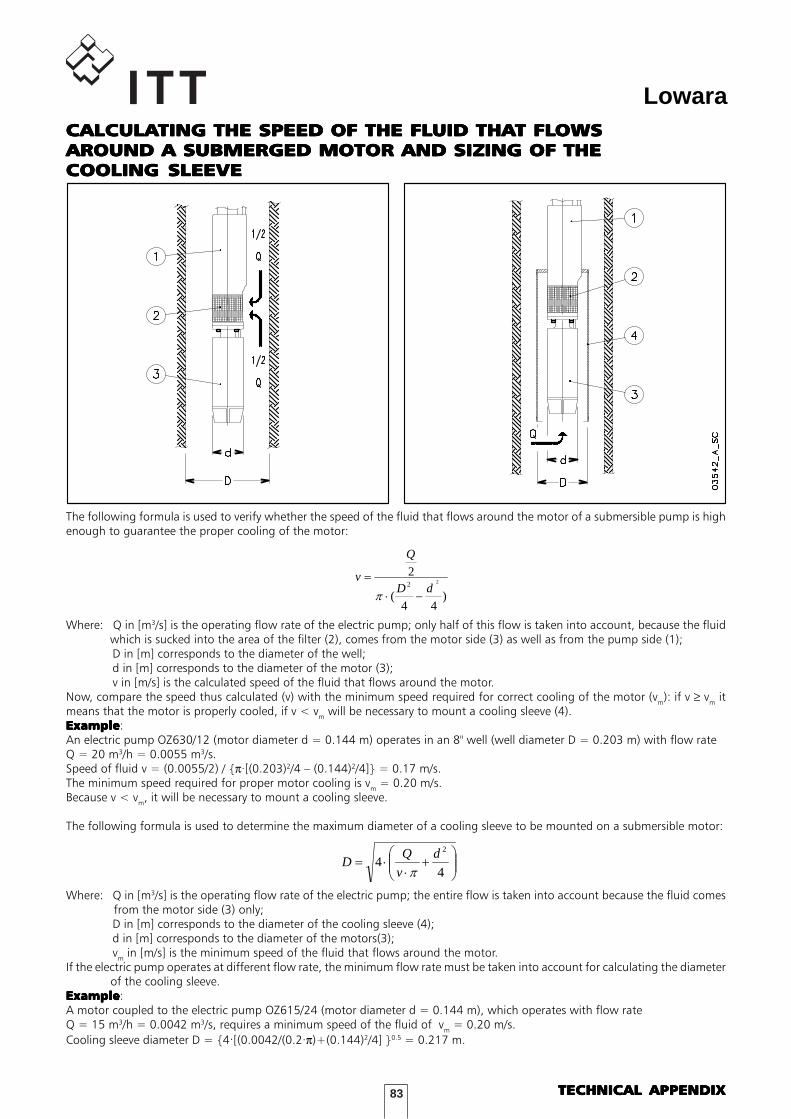
83
LowaraCALCULACALCULACALCULACALCULACALCULATING THE SPEED OF THE FLTING THE SPEED OF THE FLTING THE SPEED OF THE FLTING THE SPEED OF THE FLTING THE SPEED OF THE FLUID THAUID THAUID THAUID THAUID THAT FLT FLT FLT FLT FLOWSOWSOWSOWSOWSAROUND A SUBMERGED MOTOR AND SIZING OF THEAROUND A SUBMERGED MOTOR AND SIZING OF THEAROUND A SUBMERGED MOTOR AND SIZING OF THEAROUND A SUBMERGED MOTOR AND SIZING OF THEAROUND A SUBMERGED MOTOR AND SIZING OF THECOOLING SLEEVECOOLING SLEEVECOOLING SLEEVECOOLING SLEEVECOOLING SLEEVE
TECHNICAL APPENDIXTECHNICAL APPENDIXTECHNICAL APPENDIXTECHNICAL APPENDIXTECHNICAL APPENDIX
The following formula is used to verify whether the speed of the fluid that flows around the motor of a submersible pump is highenough to guarantee the proper cooling of the motor:
)
44(
222 dD
Q
v
−⋅
=
π
Where: Q in [m3/s] is the operating flow rate of the electric pump; only half of this flow is taken into account, because the fluid which is sucked into the area of the filter (2), comes from the motor side (3) as well as from the pump side (1);
D in [m] corresponds to the diameter of the well;d in [m] corresponds to the diameter of the motor (3);v in [m/s] is the calculated speed of the fluid that flows around the motor.
Now, compare the speed thus calculated (v) with the minimum speed required for correct cooling of the motor (vm): if v ≥ vm itmeans that the motor is properly cooled, if v < vm will be necessary to mount a cooling sleeve (4).ExampleExampleExampleExampleExample:An electric pump OZ630/12 (motor diameter d = 0.144 m) operates in an 8" well (well diameter D = 0.203 m) with flow rateQ = 20 m3/h = 0.0055 m3/s.Speed of fluid v = (0.0055/2) / {π·[(0.203)2/4 – (0.144)2/4]} = 0.17 m/s.The minimum speed required for proper motor cooling is vm = 0.20 m/s.Because v < vm, it will be necessary to mount a cooling sleeve.
The following formula is used to determine the maximum diameter of a cooling sleeve to be mounted on a submersible motor:
⎟⎟⎠
⎞⎜⎜⎝
⎛+
⋅⋅=
44
2d
v
QD
π
Where: Q in [m3/s] is the operating flow rate of the electric pump; the entire flow is taken into account because the fluid comes from the motor side (3) only;
D in [m] corresponds to the diameter of the cooling sleeve (4);d in [m] corresponds to the diameter of the motors(3);vm in [m/s] is the minimum speed of the fluid that flows around the motor.
If the electric pump operates at different flow rate, the minimum flow rate must be taken into account for calculating the diameter of the cooling sleeve.ExampleExampleExampleExampleExample:A motor coupled to the electric pump OZ615/24 (motor diameter d = 0.144 m), which operates with flow rateQ = 15 m3/h = 0.0042 m3/s, requires a minimum speed of the fluid of vm = 0.20 m/s.Cooling sleeve diameter D = {4·[(0.0042/(0.2·π)+(0.144)2/4] }0.5 = 0.217 m.
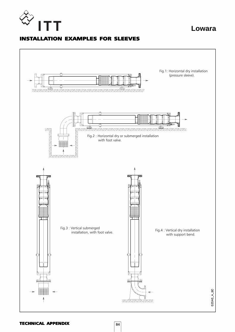
84
Lowara
Fig.1: Horizontal dry installation (pressure sleeve).
Fig.2 : Horizontal dry or submerged installation with foot valve.
Fig.3 : Vertical submerged installation, with foot valve.
Fig.4 : Vertical dry installation with support bend.
INSTINSTINSTINSTINSTALLAALLAALLAALLAALLATION EXAMPLES FOR SLEEVESTION EXAMPLES FOR SLEEVESTION EXAMPLES FOR SLEEVESTION EXAMPLES FOR SLEEVESTION EXAMPLES FOR SLEEVES
TECHNICAL APPENDIXTECHNICAL APPENDIXTECHNICAL APPENDIXTECHNICAL APPENDIXTECHNICAL APPENDIX
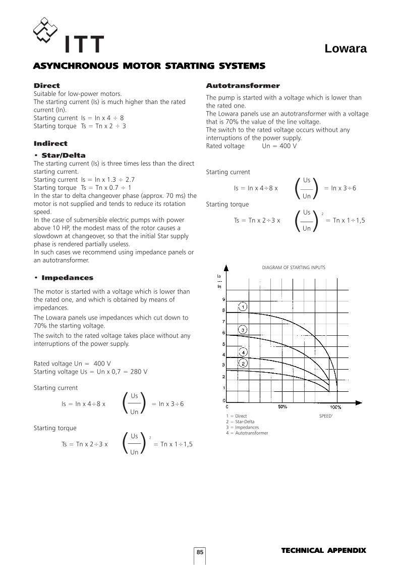
85
LowaraASYNCHRONOUS MOTOR STASYNCHRONOUS MOTOR STASYNCHRONOUS MOTOR STASYNCHRONOUS MOTOR STASYNCHRONOUS MOTOR STARTING SYSTEMSARTING SYSTEMSARTING SYSTEMSARTING SYSTEMSARTING SYSTEMS
DirectSuitable for low-power motors.The starting current (Is) is much higher than the ratedcurrent (In).Starting current Is = In x 4 ÷ 8Starting torque Ts = Tn x 2 ÷ 3
Indirect
• Star/DeltaThe starting current (Is) is three times less than the directstarting current.Starting current Is = In x 1.3 ÷ 2.7Starting torque Ts = Tn x 0.7 ÷ 1In the star to delta changeover phase (approx. 70 ms) themotor is not supplied and tends to reduce its rotationspeed. In the case of submersible electric pumps with powerabove 10 HP, the modest mass of the rotor causes aslowdown at changeover, so that the initial Star supplyphase is rendered partially useless.In such cases we recommend using impedance panels oran autotransformer.
• Impedances
The motor is started with a voltage which is lower thanthe rated one, and which is obtained by means ofimpedances.The Lowara panels use impedances which cut down to70% the starting voltage.The switch to the rated voltage takes place without anyinterruptions of the power supply.
Rated voltage Un = 400 VStarting voltage Us = Un x 0,7 = 280 V
Starting currentUs
Is = In x 4÷8 x = In x 3÷6Un
Starting torqueUs
Ts = Tn x 2÷3 x 2
= Tn x 1÷1,5Un
DIAGRAM OF STARTING INPUTS
1 = Direct SPEED’2 = Star-Delta3 = Impedances4 = Autotransformer
Autotransformer
The pump is started with a voltage which is lower thanthe rated one.The Lowara panels use an autotransformer with a voltagethat is 70% the value of the line voltage.The switch to the rated voltage occurs without anyinterruptions of the power supply.Rated voltage Un = 400 V
Starting currentUs
Is = In x 4÷8 x = In x 3÷6Un
Starting torqueUs
Ts = Tn x 2÷3 x 2
= Tn x 1÷1,5Un
(
(
)
)
((
))
Ia
TECHNICAL APPENDIXTECHNICAL APPENDIXTECHNICAL APPENDIXTECHNICAL APPENDIXTECHNICAL APPENDIX
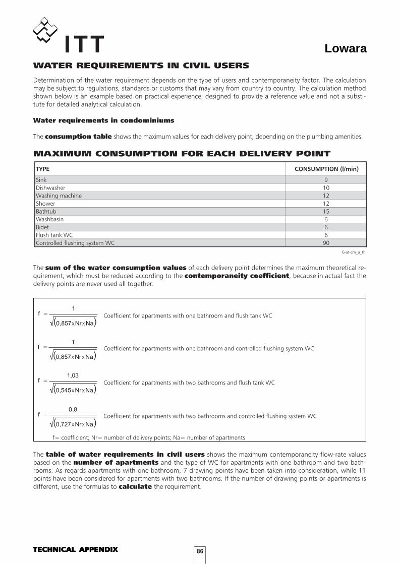
86
LowaraWATER REQUIREMENTS IN CIVIL USERS
Determination of the water requirement depends on the type of users and contemporaneity factor. The calculationmay be subject to regulations, standards or customs that may vary from country to country. The calculation methodshown below is an example based on practical experience, designed to provide a reference value and not a substi-tute for detailed analytical calculation.
Water requirements in condominiums
The consumption table shows the maximum values for each delivery point, depending on the plumbing amenities.
MAXIMUM CONSUMPTION FOR EACH DELIVERY POINT
TYPE CONSUMPTION (l/min)
Sink 9Dishwasher 10Washing machine 12Shower 12Bathtub 15Washbasin 6Bidet 6Flush tank WC 6Controlled flushing system WC 90
G-at-cm_a_th
The sum of the water consumption values of each delivery point determines the maximum theoretical re-quirement, which must be reduced according to the contemporaneity coefficient, because in actual fact thedelivery points are never used all together.
The table of water requirements in civil users shows the maximum contemporaneity flow-rate valuesbased on the number of apartments and the type of WC for apartments with one bathroom and two bath-rooms. As regards apartments with one bathroom, 7 drawing points have been taken into consideration, while 11points have been considered for apartments with two bathrooms. If the number of drawing points or apartments isdifferent, use the formulas to calculate the requirement.
( )NaNr857,0
1f
xx
=
( )NaNr857,0
1f
xx
=
( )NaNr545,0
03,1f
xx
=
( )NaNr727,0
8,0f
xx
=
Coefficient for apartments with one bathroom and flush tank WC
Coefficient for apartments with one bathroom and controlled flushing system WC
Coefficient for apartments with two bathrooms and flush tank WC
Coefficient for apartments with two bathrooms and controlled flushing system WC
f= coefficient; Nr= number of delivery points; Na= number of apartments
TECHNICAL APPENDIXTECHNICAL APPENDIXTECHNICAL APPENDIXTECHNICAL APPENDIXTECHNICAL APPENDIX
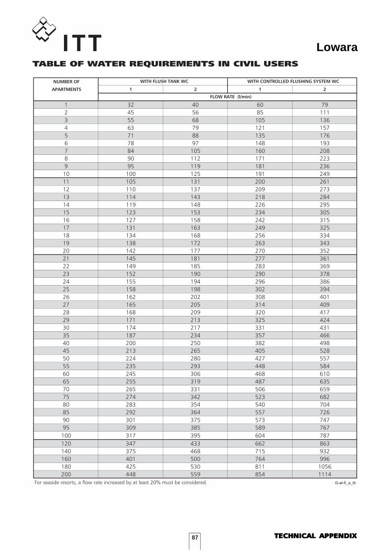
87
Lowara
NUMBER OF
APARTMENTS 1 2 1 2
1 32 40 60 792 45 56 85 1113 55 68 105 1364 63 79 121 1575 71 88 135 1766 78 97 148 1937 84 105 160 2088 90 112 171 2239 95 119 181 236
10 100 125 191 24911 105 131 200 26112 110 137 209 27313 114 143 218 28414 119 148 226 29515 123 153 234 30516 127 158 242 31517 131 163 249 32518 134 168 256 33419 138 172 263 34320 142 177 270 35221 145 181 277 36122 149 185 283 36923 152 190 290 37824 155 194 296 38625 158 198 302 39426 162 202 308 40127 165 205 314 40928 168 209 320 41729 171 213 325 42430 174 217 331 43135 187 234 357 46640 200 250 382 49845 213 265 405 52850 224 280 427 55755 235 293 448 58460 245 306 468 61065 255 319 487 63570 265 331 506 65975 274 342 523 68280 283 354 540 70485 292 364 557 72690 301 375 573 74795 309 385 589 767
100 317 395 604 787120 347 433 662 863140 375 468 715 932160 401 500 764 996180 425 530 811 1056200 448 559 854 1114
For seaside resorts, a flow rate increased by at least 20% must be considered. G-at-fi_a_th
FLOW RATE (l/min)
WITH FLUSH TANK WC WITH CONTROLLED FLUSHING SYSTEM WC
TABLE OF WATER REQUIREMENTS IN CIVIL USERS
TECHNICAL APPENDIXTECHNICAL APPENDIXTECHNICAL APPENDIXTECHNICAL APPENDIXTECHNICAL APPENDIX
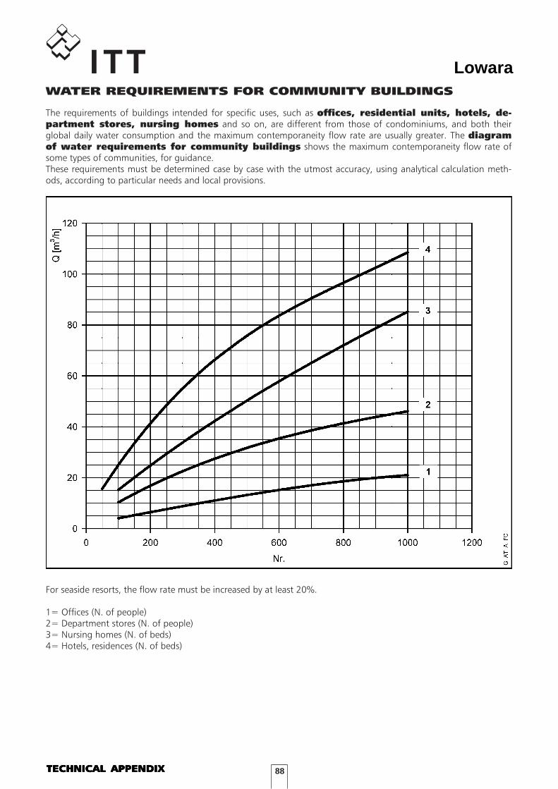
88
LowaraWATER REQUIREMENTS FOR COMMUNITY BUILDINGS
For seaside resorts, the flow rate must be increased by at least 20%.
1= Offices (N. of people)2= Department stores (N. of people)3= Nursing homes (N. of beds)4= Hotels, residences (N. of beds)
The requirements of buildings intended for specific uses, such as offices, residential units, hotels, de-partment stores, nursing homes and so on, are different from those of condominiums, and both theirglobal daily water consumption and the maximum contemporaneity flow rate are usually greater. The diagramof water requirements for community buildings shows the maximum contemporaneity flow rate ofsome types of communities, for guidance.These requirements must be determined case by case with the utmost accuracy, using analytical calculation meth-ods, according to particular needs and local provisions.
TECHNICAL APPENDIXTECHNICAL APPENDIXTECHNICAL APPENDIXTECHNICAL APPENDIXTECHNICAL APPENDIX
89
LowaraNPSH
The minimum operating values that can be reached atthe pump suction end are limited by the onset ofcavitation.
Cavitation is the formation of vapour-filled cavitieswithin liquids where the pressure is locally reduced toa critical value, or where the local pressure is equal to,or just below the vapour pressure of the liquid.
The vapour-filled cavities flow with the current andwhen they reach a higher pressure area the vapourcontained in the cavities condenses. The cavitiescollide, generating pressure waves that are transmittedto the walls. These, being subjected to stress cycles,gradually become deformed and yield due to fatigue.This phenomenon, characterized by a metallic noiseproduced by the hammering on the pipe walls, iscalled incipient cavitation.
The damage caused by cavitation may be magnified byelectrochemical corrosion and a local r ise intemperature due to the plastic deformation of thewalls. The materials that offer the highest resistance toheat and corrosion are alloy steels, especially austeniticsteel. The conditions that trigger cavitation may beassessed by calculating the total net suction head,referred to in technical literature with the acronymNPSH (Net Positive Suction Head).
The NPSH represents the total energy (expressed in m.)of the liquid measured at suction under conditions ofincipient cavitation, excluding the vapour pressure(expressed in m.) that the liquid has at the pump inlet.
To find the static height hz at which to install themachine under safe conditions, the following formulamust be verified:
hp + hz ≥ (NPSHr + 0.5) + hf + hpv ➀
where:hp is the absolute pressure applied to the free liquid
surface in the suction tank, expressed in m. ofliquid; hp is the quotient between the barometricpressure and the specific weight of the liquid.
hz is the suction lift between the pump axis and thefree liquid surface in the suction tank, expressedin m.; hz is negative when the liquid level is lowerthan the pump axis.
hf is the flow resistance in the suction line and itsaccessories, such as: fittings, foot valve, gatevalve, elbows, etc.
hpv is the vapour pressure of the liquid at theoperating temperature, expressed in m. of liquid. hpv is the quotient between the Pv vapourpressure and the liquid's specific weight.
0.5 is the safety factor.
The maximum possible suction head for installationdepends on the value of the atmospheric pressure(i.e. the elevation above sea level at which the pumpis installed) and the temperature of the liquid.
To help the user, with reference to water temperature(4°C) and to the elevation above sea level, thefollowing tables show the drop in hydraulic pressurehead in relation to the elevation above sea level, andthe suction loss in relation to temperature.
Water20 40 60 80 90 110 120temperature (°C)
Suction0,2 0,7 2,0 5,0 7,4 15,4 21,5loss (m)
Elevation above500 1000 1500 2000 25003000sea level (m)
Suction0,55 1,1 1,65 2,2 2,75 3,3loss (m)
Flow resistance is shown in the tables at pages 91-92of this catalogue. To reduce it to a minimum,especially in cases of high suction head (over 4-5 m.)or within the operating limits with high flow rates, werecommend using a suction line having a largerdiameter than that of the pump's suction port.It is always a good idea to position the pump as closeas possible to the liquid to be pumped.
Make the following calculation:
Liquid: water at ∼ 15°C y = 1 kg/dm3
Flow rate required: 30 m3/hHead for required delivery: 43 m.Suction lift: 3.5 m.The selection is an FHE 40-200/75 pump whose NPSHrequired value is, at 30 m3/h, 2.5 m.
For water at 15°C the hpv term is Pv = 0,174 m (0.01701 bar)γ
and hp = Pa = 10,33mγ
The Hf flow resistance in the suction line with footvalves is ∼1.2 m.By substituting the parameters in formula ➀ with thenumeric values above, we have:
10.33 + (-3.5) ≥ (2.5 + 0.5) + 1.2 + 0.17
from which we have: 6.8 > 4.4
The relation is therefore verified.
TECHNICAL APPENDIXTECHNICAL APPENDIXTECHNICAL APPENDIXTECHNICAL APPENDIXTECHNICAL APPENDIX
90
Lowara
t T ps ρ ρ ρt T ps t T ps
°C K bar kg/dm3 °C K bar kg/dm3 °C K bar kg/dm3
0 273,15 0,00611 0,9998 55 328,15 0,15741 0,9857 120 393,15 1,9854 0,94291 274,15 0,00657 0,9999 56 329,15 0,16511 0,9852 122 395,15 2,1145 0,94122 275,15 0,00706 0,9999 57 330,15 0,17313 0,9846 124 397,15 2,2504 0,93963 276,15 0,00758 0,9999 58 331,15 0,18147 0,9842 126 399,15 2,3933 0,93794 277,15 0,00813 1,0000 59 332,15 0,19016 0,9837 128 401,15 2,5435 0,93625 278,15 0,00872 1,0000 60 333,15 0,1992 0,9832 130 403,15 2,7013 0,93466 279,15 0,00935 1,0000 61 334,15 0,2086 0,9826 132 405,15 2,867 0,93287 280,15 0,01001 0,9999 62 335,15 0,2184 0,9821 134 407,15 3,041 0,93118 281,15 0,01072 0,9999 63 336,15 0,2286 0,9816 136 409,15 3,223 0,92949 282,15 0,01147 0,9998 64 337,15 0,2391 0,9811 138 411,15 3,414 0,9276
10 283,15 0,01227 0,9997 65 338,15 0,2501 0,9805 140 413,15 3,614 0,925811 284,15 0,01312 0,9997 66 339,15 0,2615 0,9799 145 418,15 4,155 0,921412 285,15 0,01401 0,9996 67 340,15 0,2733 0,9793 155 428,15 5,433 0,912113 286,15 0,01497 0,9994 68 341,15 0,2856 0,9788 160 433,15 6,181 0,907314 287,15 0,01597 0,9993 69 342,15 0,2984 0,9782 165 438,15 7,008 0,902415 288,15 0,01704 0,9992 70 343,15 0,3116 0,9777 170 433,15 7,920 0,897316 289,15 0,01817 0,9990 71 344,15 0,3253 0,9770 175 448,15 8,924 0,892117 290,15 0,01936 0,9988 72 345,15 0,3396 0,9765 180 453,15 10,027 0,886918 291,15 0,02062 0,9987 73 346,15 0,3543 0,9760 185 458,15 11,233 0,881519 292,15 0,02196 0,9985 74 347,15 0,3696 0,9753 190 463,15 12,551 0,876020 293,15 0,02337 0,9983 75 348,15 0,3855 0,9748 195 468,15 13,987 0,870421 294,15 0,24850 0,9981 76 349,15 0,4019 0,9741 200 473,15 15,550 0,864722 295,15 0,02642 0,9978 77 350,15 0,4189 0,9735 205 478,15 17,243 0,858823 296,15 0,02808 0,9976 78 351,15 0,4365 0,9729 210 483,15 19,077 0,852824 297,15 0,02982 0,9974 79 352,15 0,4547 0,9723 215 488,15 21,060 0,846725 298,15 0,03166 0,9971 80 353,15 0,4736 0,9716 220 493,15 23,198 0,840326 299,15 0,03360 0,9968 81 354,15 0,4931 0,9710 225 498,15 25,501 0,833927 300,15 0,03564 0,9966 82 355,15 0,5133 0,9704 230 503,15 27,976 0,827328 301,15 0,03778 0,9963 83 356,15 0,5342 0,9697 235 508,15 30,632 0,820529 302,15 0,04004 0,9960 84 357,15 0,5557 0,9691 240 513,15 33,478 0,813630 303,15 0,04241 0,9957 85 358,15 0,5780 0,9684 245 518,15 36,523 0,806531 304,15 0,04491 0,9954 86 359,15 0,6011 0,9678 250 523,15 39,776 0,799232 305,15 0,04753 0,9951 87 360,15 0,6249 0,9671 255 528,15 43,246 0,791633 306,15 0,05029 0,9947 88 361,15 0,6495 0,9665 260 533,15 46,943 0,783934 307,15 0,05318 0,9944 89 362,15 0,6749 0,9658 265 538,15 50,877 0,775935 308,15 0,05622 0,9940 90 363,15 0,7011 0,9652 270 543,15 55,058 0,767836 309,15 0,05940 0,9937 91 364,15 0,7281 0,9644 275 548,15 59,496 0,759337 310,15 0,06274 0,9933 92 365,15 0,7561 0,9638 280 553,15 64,202 0,750538 311,15 0,06624 0,9930 93 366,15 0,7849 0,9630 285 558,15 69,186 0,741539 312,15 0,06991 0,9927 94 367,15 0,8146 0,9624 290 563,15 74,461 0,732140 313,15 0,07375 0,9923 95 368,15 0,8453 0,9616 295 568,15 80,037 0,722341 314,15 0,07777 0,9919 96 369,15 0,8769 0,9610 300 573,15 85,927 0,712242 315,15 0,08198 0,9915 97 370,15 0,9094 0,9602 305 578,15 92,144 0,701743 316,15 0,09639 0,9911 98 371,15 0,9430 0,9596 310 583,15 98,70 0,690644 317,15 0,09100 0,9907 99 372,15 0,9776 0,9586 315 588,15 105,61 0,679145 318,15 0,09582 0,9902 100 373,15 1,0133 0,9581 320 593,15 112,89 0,666946 319,15 0,10086 0,9898 102 375,15 1,0878 0,9567 325 598,15 120,56 0,654147 320,15 0,10612 0,9894 104 377,15 1,1668 0,9552 330 603,15 128,63 0,640448 321,15 0,11162 0,9889 106 379,15 1,2504 0,9537 340 613,15 146,05 0,610249 322,15 0,11736 0,9884 108 381,15 1,3390 0,9522 350 623,15 165,35 0,574350 323,15 0,12335 0,9880 110 383,15 1,4327 0,9507 360 633,15 186,75 0,527551 324,15 0,12961 0,9876 112 385,15 1,5316 0,9491 370 643,15 210,54 0,451852 325,15 0,13613 0,9871 114 387,15 1,6362 0,9476 374,15 647,30 221,20 0,315453 326,15 0,14293 0,9862 116 389,15 1,7465 0,946054 327,15 0,15002 0,9862 118 391,15 1,8628 0,9445
G-at_npsh_a_sc
TECHNICAL APPENDIX VAPOUR PRESSURE PS VAPOURPRESSURE AND ρ DENSITY OF WATER TABLE
TECHNICAL APPENDIXTECHNICAL APPENDIXTECHNICAL APPENDIXTECHNICAL APPENDIXTECHNICAL APPENDIX
91
LowaraTABLE OF FLOW RESISTANCE IN 100 m OF STRAIGHT CASTIRON PIPELINE (HAZEN-WILLIAMS FORMULA C=100)
m3/h l/min 15 20 25 32 40 50 65 80 100 125 150 175 200 250 300 350 4001/2" 3/4" 1" 1 1/4" 1 1/2" 2 2 1/2" 3" 4" 5" 6" 7" 8" 10" 12" 14" 16"
v 0,94 0,53 0,34 0,21 0,13 hr 16 3,94 1,33 0,40 0,13 The hr values must be multiplied by:v 1,42 0,80 0,51 0,31 0,20 0.71 for galvanized or painted steel pipeshr 33,9 8,35 2,82 0,85 0,29 0.54 for stainless steel or copper pipesv 1,89 1,06 0,68 0,41 0,27 0,17 0.47 for PVC or PE pipeshr 57,7 14,21 4,79 1,44 0,49 0,16 v 2,36 1,33 0,85 0,52 0,33 0,21hr 87,2 21,5 7,24 2,18 0,73 0,25v 2,83 1,59 1,02 0,62 0,40 0,25hr 122 30,1 10,1 3,05 1,03 0,35v 3,30 1,86 1,19 0,73 0,46 0,30hr 162 40,0 13,5 4,06 1,37 0,46v 2,12 1,36 0,83 0,53 0,34 0,20hr 51,2 17,3 5,19 1,75 0,59 0,16v 2,65 1,70 1,04 0,66 0,42 0,25hr 77,4 26,1 7,85 2,65 0,89 0,25v 3,18 2,04 1,24 0,80 0,51 0,30hr 108 36,6 11,0 3,71 1,25 0,35v 3,72 2,38 1,45 0,93 0,59 0,35hr 144 48,7 14,6 4,93 1,66 0,46v 4,25 2,72 1,66 1,06 0,68 0,40hr 185 62,3 18,7 6,32 2,13 0,59v 3,06 1,87 1,19 0,76 0,45 0,30hr 77,5 23,3 7,85 2,65 0,74 0,27v 3,40 2,07 1,33 0,85 0,50 0,33hr 94,1 28,3 9,54 3,22 0,90 0,33v 4,25 2,59 1,66 1,06 0,63 0,41hr 142 42,8 14,4 4,86 1,36 0,49v 3,11 1,99 1,27 0,75 0,50 0,32hr 59,9 20,2 6,82 1,90 0,69 0,23v 3,63 2,32 1,49 0,88 0,58 0,37hr 79,7 26,9 9,07 2,53 0,92 0,31v 4,15 2,65 1,70 1,01 0,66 0,42hr 102 34,4 11,6 3,23 1,18 0,40v 5,18 3,32 2,12 1,26 0,83 0,53 0,34hr 154 52,0 17,5 4,89 1,78 0,60 0,20v 3,98 2,55 1,51 1,00 0,64 0,41hr 72,8 24,6 6,85 2,49 0,84 0,28v 5,31 3,40 2,01 1,33 0,85 0,54 0,38hr 124 41,8 11,66 4,24 1,43 0,48 0,20v 6,63 4,25 2,51 1,66 1,06 0,68 0,47hr 187 63,2 17,6 6,41 2,16 0,73 0,30v 5,10 3,02 1,99 1,27 0,82 0,57 0,42hr 88,6 24,7 8,98 3,03 1,02 0,42 0,20v 5,94 3,52 2,32 1,49 0,95 0,66 0,49hr 118 32,8 11,9 4,03 1,36 0,56 0,26v 6,79 4,02 2,65 1,70 1,09 0,75 0,55hr 151 42,0 15,3 5,16 1,74 0,72 0,34v 7,64 4,52 2,99 1,91 1,22 0,85 0,62hr 188 52,3 19,0 6,41 2,16 0,89 0,42v 5,03 3,32 2,12 1,36 0,94 0,69 0,53hr 63,5 23,1 7,79 2,63 1,08 0,51 0,27v 6,28 4,15 2,65 1,70 1,18 0,87 0,66hr 96,0 34,9 11,8 3,97 1,63 0,77 0,40v 7,54 4,98 3,18 2,04 1,42 1,04 0,80hr 134 48,9 16,5 5,57 2,29 1,08 0,56v 8,79 5,81 3,72 2,38 1,65 1,21 0,93hr 179 65,1 21,9 7,40 3,05 1,44 0,75v 6,63 4,25 2,72 1,89 1,39 1,06 0,68hr 83,3 28,1 9,48 3,90 1,84 0,96 0,32v 8,29 5,31 3,40 2,36 1,73 1,33 0,85hr 126 42,5 14,3 5,89 2,78 1,45 0,49v 6,37 4,08 2,83 2,08 1,59 1,02 0,71hr 59,5 20,1 8,26 3,90 2,03 0,69 0,28v 7,43 4,76 3,30 2,43 1,86 1,19 0,83hr 79,1 26,7 11,0 5,18 2,71 0,91 0,38v 8,49 5,44 3,77 2,77 2,12 1,36 0,94hr 101 34,2 14,1 6,64 3,46 1,17 0,48v 6,79 4,72 3,47 2,65 1,70 1,18hr 51,6 21,2 10,0 5,23 1,77 0,73v 8,15 5,66 4,16 3,18 2,04 1,42hr 72,3 29,8 14,1 7,33 2,47 1,02v 6,61 4,85 3,72 2,38 1,65 1,21hr 39,6 18,7 9,75 3,29 1,35 0,64v 7,55 5,55 4,25 2,72 1,89 1,39hr 50,7 23,9 12,49 4,21 1,73 0,82v 8,49 6,24 4,78 3,06 2,12 1,56 1,19hr 63,0 29,8 15,5 5,24 2,16 1,02 0,53v 6,93 5,31 3,40 2,36 1,73 1,33hr 36,2 18,9 6,36 2,62 1,24 0,65
G-at-pct_a_th
hr = flow resistance for 100m of straight pipeline (m)V = water speed (m/s)
420 7000
600 10000
8000480
540 9000
210 3500
360 6000
240 4000
300 5000
180 3000
2000120
150 2500
250
1500
100060
90
75 1250
500
800
600
400
90
175
48
36
24
15
10,5
18 300
30
4,2 70
3 50
150
12 200
4,8 80
0,9 15
0,6 10
5,4
1,2 20
1,8 30
2,1 35
1,5 25
2,4 40
3,6 60
6 100
7,5 125
FLOW RATE NOMINAL DIAMETER in mm and INCHES
105 1750
42 700
54 900
9
TECHNICAL APPENDIXTECHNICAL APPENDIXTECHNICAL APPENDIXTECHNICAL APPENDIXTECHNICAL APPENDIX
92
LowaraFLOW RESISTANCE
TABLE OF FLOW RESISTANCE IN BENDS, VALVES AND GATES
The flow resistance is calculated using the equivalent pipeline length method according to the table below:
The table is valid for the Hazen Williams coefficient C = 100 (cast iron pipework). For steel pipework, multiply thevalues by 1.41. For stainless steel, copper and coated cast iron pipework, multiply the values by 1.85.When the equivalent pipeline length has been determined, the flow resistance is obtained from the table offlow resistance.The values given are guideline values which are bound to vary slightly according to the model, especially for gatevalves and non-return valves, for which it is a good idea to check the values supplied by the manufacturers.
ACCESSORY
TYPE 25 32 40 50 65 80 100 125 150 200 250 300
45° bend 0,2 0,2 0,4 0,4 0,6 0,6 0,9 1,1 1,5 1,9 2,4 2,890° bend 0,4 0,6 0,9 1,1 1,3 1,5 2,1 2,6 3,0 3,9 4,7 5,890° smooth bend 0,4 0,4 0,4 0,6 0,9 1,1 1,3 1,7 1,9 2,8 3,4 3,9Union tee or cross 1,1 1,3 1,7 2,1 2,6 3,2 4,3 5,3 6,4 7,5 10,7 12,8Gate - - - 0,2 0,2 0,2 0,4 0,4 0,6 0,9 1,1 1,3Non return valve 1,1 1,5 1,9 2,4 3,0 3,4 4,7 5,9 7,4 9,6 11,8 13,9
G-a-pcv_a_th
DN
Equivalent pipeline length (m)
TECHNICAL APPENDIXTECHNICAL APPENDIXTECHNICAL APPENDIXTECHNICAL APPENDIXTECHNICAL APPENDIX
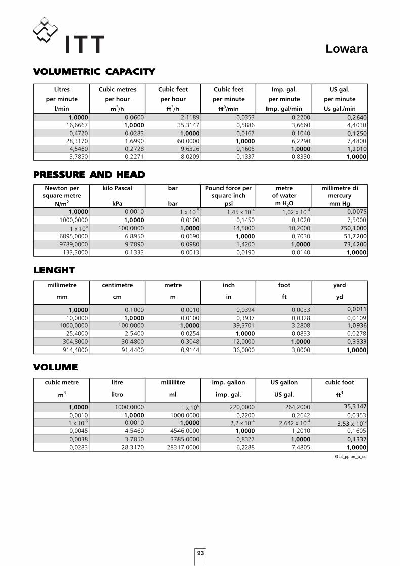
93
Lowara
VOLUMETRIC CAPACITY
Litres Cubic metres Cubic feet Cubic feet Imp. gal. US gal.
per minute per hour per hour per minute per minute per minute
l/min m3/h ft
3/h ft
3/min Imp. gal/min Us gal./min
1,0000 0,0600 2,1189 0,0353 0,2200 0,2640
16,6667 1,0000 35,3147 0,5886 3,6660 4,4030
0,4720 0,0283 1,0000 0,0167 0,1040 0,1250
28,3170 1,6990 60,0000 1,0000 6,2290 7,4800
4,5460 0,2728 9,6326 0,1605 1,0000 1,2010
3,7850 0,2271 8,0209 0,1337 0,8330 1,0000
PRESSURE AND HEAD
Newton per kilo Pascal bar Pound force per metre millimetre di
square metre square inch of water mercury
N/m2 kPa bar psi m H2O mm Hg
1,0000 0,0010 1 x 10⁻⁵ 1,45 x 10⁻⁴ 1,02 x 10⁻⁴ 0,0075
1000,0000 1,0000 0,0100 0,1450 0,1020 7,5000
1 x 10⁵ 100,0000 1,0000 14,5000 10,2000 750,1000
6895,0000 6,8950 0,0690 1,0000 0,7030 51,7200
9789,0000 9,7890 0,0980 1,4200 1,0000 73,4200
133,3000 0,1333 0,0013 0,0190 0,0140 1,0000
LENGHT
millimetre centimetre metre inch foot yard
mm cm m in ft yd
1,0000 0,1000 0,0010 0,0394 0,0033 0,0011
10,0000 1,0000 0,0100 0,3937 0,0328 0,01091000,0000 100,0000 1,0000 39,3701 3,2808 1,0936
25,4000 2,5400 0,0254 1,0000 0,0833 0,0278
304,8000 30,4800 0,3048 12,0000 1,0000 0,3333
914,4000 91,4400 0,9144 36,0000 3,0000 1,0000
VOLUME
cubic metre litre millilitre imp. gallon US gallon cubic foot
m3 litro ml imp. gal. US gal. ft
3
1,0000 1000,0000 1 x 10⁶ 220,0000 264,2000 35,3147
0,0010 1,0000 1000,0000 0,2200 0,2642 0,0353
1 x 10⁻⁶ 0,0010 1,0000 2,2 x 10⁻⁴ 2,642 x 10-43,53 x 10
-5
0,0045 4,5460 4546,0000 1,0000 1,2010 0,1605
0,0038 3,7850 3785,0000 0,8327 1,0000 0,1337
0,0283 28,3170 28317,0000 6,2288 7,4805 1,0000
G-at_pp-en_a_sc
VVVVVOLOLOLOLOLUMETRIC CAPUMETRIC CAPUMETRIC CAPUMETRIC CAPUMETRIC CAPACITYACITYACITYACITYACITY
PRESPRESPRESPRESPRESSURE AND HEADSURE AND HEADSURE AND HEADSURE AND HEADSURE AND HEAD
LENGHTLENGHTLENGHTLENGHTLENGHT
VVVVVOLOLOLOLOLUMEUMEUMEUMEUME
94
Lowara

Lowara
cod. 000000001 P 01/08
Lowara reserves the right to make modification without prior notice.
Headquarters
LOWARA S.r.l.Via Dott. Lombardi, 1436075 Montecchio MaggioreVicenza - ItalyTel. (+39) 0444 707111Fax (+39) 0444 492166e-mail: [email protected] - http: //www.lowara.com
Customer Service
848 787011For Italian market only
®
Do it 100%
RECYCLEDPAPER
“RESIDENTIAL AND COMMERCIAL WATER GROUP - EMEA” SALES NETWORK
ITALY
MILANO 20090 Cusago - Viale Europa, 30Tel. (+39) 02 90394188Fax (+39) 0444 707176e-mail: [email protected]
BOLOGNA 40132 - Via Marco Emilio Lepido, 178Tel. (+39) 051 6415666Fax (+39) 0444 707178e-mail: [email protected]
VICENZA 36061 Bassano del Grappa - Via Pigafetta, 6Tel. (+39) 0424 566776 (R.A. 3 Linee)Fax (+39) 0424 566773e-mail: [email protected]
PADOVA 35020 Albignasego - Via A. Volta, 56 - Zona MandriolaTel. (+39) 049 8801110Fax (+39) 049 8801408e-mail: [email protected]
ROMA 00173 Via Frascineto, 8Tel. (+39) 06 7235890 (2 linee)Fax (+39) 0444 707180e-mail: [email protected]
CAGLIARI 09122 - Via Dolcetta, 3Tel. (+39) 070 287762 - 292192Fax (+39) 0444 707179e-mail: [email protected]
CATANIA 95027 S. Gregorio - Via XX Settembre, 75Tel. (+39) 095 7123226 - 7123987Fax (+39) 095 498902e-mail: [email protected]
EUROPEPumpenfabrik ERNST VOGEL GmbHA-2000 STOCKERAUErnst Vogel-Straße 2Tel. (+43) 02266 604 - Fax (+43) 02266 65311e-mail: [email protected] - http://www.vogel-pumpen.comLOWARA DEUTSCHLAND GMBHBiebigheimer Straße 12D-63762 GroßostheimTel. (+49) 0 60 26 9 43 - 0 - Fax (+49) 0 60 26 9 43 - 2 10e-mail: [email protected] - http://www.lowara.deLOWARA FRANCE S.A.S.BP 5731137073 Tours Cedex 2Tel. (+33) 02 47 88 17 17 - Fax (+33) 02 47 88 17 00e-mail: [email protected] - http://www.lowara.frLOWARA FRANCE SAS Agence SudZ.I. La Sipière - BP 2313730 Saint Victoret - FTel. (+33) 04 42 10 02 30 - Fax (+33) 04 42 10 43 75http://www.lowara.frLOWARA NEDERLAND B.V.Zandweistraat 224181 CG WaardenburgTel. (+31) 0418 655060 - Fax (+31) 0418 655061e-mail: [email protected] - http://www.lowara.nlITT PORTUGAL, Unipessoal, Lda.Praçeta da Castanheira, 384475-019 BarcaTel. (+351) 22 9478550 - Fax (+351) 22 9478570e-mail: [email protected] - http://www.lowara.ptITT PORTUGAL, Unipessoal, Lda. DelegaçãoQuinta da Fonte - Edificio D. Pedro I2770-071 Paço de ArcosTel. (+351) 21 0001628 - Fax (+351) 21 0001675LOWARA UK LTD.Millwey Rise, Industrial EstateAxminster - Devon EX13 5HU UKTel. (+44) 01297 630200 - Fax (+44) 01297 630270e-mail: [email protected] - http://www.lowara.co.ukLOWARA IRELAND LTD.59, Broomhill Drive - Tallaght Industrial EstateTallaght - DUBLIN 24Tel. (+353) 01 4520266 - Fax (+353) 01 4520725e-mail: [email protected] - http://www.lowara.ieLOWARA VOGEL POLSKA Sp. z o.o.PL 57-100 Strzelinul. Kazimierza Wielkiego 5Tel. (+48) 071 769 3900 - Fax (+48) 071 769 3909e-mail: [email protected] - http://www.lowara-vogel.pl
cod. 191005921 P 03/08