s25 cover page a2 - indian railway online training
TRANSCRIPT


S 25
TRAIN DETECTION – TRACK CIRCUITS
Issued in January 2010
INDIAN RAILWAYS INSTITUTE OF
SIGNAL ENGINEERING & TELECOMMUNICATIONS
SECUNDERABAD - 500 017

S-25
TRAIN DETECTION - TRACK CIRCUITS
CONTENTS S.No Chapter Page
No
1 Introduction 1
2 D.C Track Circuits 10
3 Insulated Rail Joints & Maintenance 22
4 Track Circuit Bonding 30
5 Audio Frequency Track Circuit 50
6 Siemens Remote-fed Coded AFTC 57
7 ALSTOM AFTC 69
8 ANNEXURE - I : ABB AFTC – STYLE TI –21 77
9 ANNEXURE - II : US & S AFTC 84
10 ANNEXURE - III : AC Track Circuits 88
11 ANNEXURE- IV: Comparison of various AFTCs in use over Indian Railways 95
12 ANNEXURE- V: Track Bonding Plan for a typical 4-Road station 96
13 QUESTIONS 97
© IRISET
http://www.iriset.ac.in
Drafted By P. Raju, IMS-2
Checked By Ch. Mohan, SPS
Approved By Ch. Mohan, SPS
DTP and Drawings G. Rajagopal, SE (D)
No. of Pages 100
Date of Issue January, 2010
Version No A2
“ This is the Intellectual property for exclusive use of Indian Railways. No part of this publication may be stored in a retrieval system, transmitted or reproduced in any way, including but not limited to photo copy, photograph, magnetic, optical or other record without the prior agreement and written permission of IRISET, Secunderabad, India”

INTRODUCTION
S 25 Page 1 TRAIN DETECTION TRACK CIRCUITS
CHAPTER – 1: INTRODUCTION 1.1 To detect the presence of a vehicle of a set portion of track is known as train detection. Basically there are two means to detect the presence of a train over a track which are
(a) Track Circuit.
(b) Axle Counters.
Typical Applications:- To detect presence of train on- Berthing Tracks , Signal Replacements, Point Zones , L.C Gate , Block Section, Automatic sections, Intermediate block sections
This notes deals with the TRACK CIRCUIT.
In a track circuit, a portion of rail track is electrically isolated from adjoining rails and included in a circuit to energise a relay. The occupation or vacancy of the track portion is detected by the condition of track relay. The length of the track confined within one circuit depends on its working feasibility. Two types of track circuit were designed. One is continuously live and is called a 'Closed Track Circuit.' The other one is made live only when occupied by vehicles and is called an 'Open Track Circuit.' The latter type is rarely used due to its serious limitations. According to the nature of supply source, the track circuits are categorised as:
(a) D.C. Track Circuits - (i) Open DC Track circuit (ii) Closed DC Track circuit
(b) A.F. Track Circuits (also known as Electronic Track Circuits)- (i) Non-Coded (ii) Coded
(c) A.C. Track Circuits - Currently used in D.C traction areas (Mumbai area with 1500 V.D.C).
1.2 DC Track Circuits The components of D.C track circuit are: -
1) Battery
2) Adjustable Resistance
3) Track Relay
4) Track Lead Cables
5) G.I. wires connecting cables to the rails
6) Continuity rail bonds
7) Insulated rail joints.

INTRODUCTION
IRISET Page 2 S 25
1.2.1 Open DC Track Circuit A schematic diagram of an 'Open Track Circuit' is given below: -
7 6 7
5
65
4
2 1 3
4
TR
Fig No.1.2.1
The circuit gets completed when the track is occupied through the net resistance of the vehicle axles occupying the track circuit.
The series resistance is so adjusted as to give sufficient voltage to the relay when axles shunt track rails with a high contact resistance. It is also to be ensured that the relay does not get, without shunt, a voltage enough to pick it up due to leakage currents through track bed ballast when damp. Otherwise, the track circuit can fail frequently.
Disadvantage : In this type of track circuit, if any connection breaks, Train `s occupation goes undetected. Hence, it is not used currently. 1.2.2 Closed Type D.C. Track Circuit
A schematic diagram of a 'Closed Track Circuit’ is connected as below:
In closed Track Circuit, feed is connected at one end of the track and the relay at the other end, which is normally energized. Track relay drops when shunted by a Train. Any breakage of rail continuity also drops the Track relay
In this track circuit, a resistance called Regulating Resistance (also referred as Track Feed Resistance) is connected in series at feed end. It serves the following purposes.
• To alter relay end voltage (Please see in Para 2.8 for details).
• It protects the feed equipment when the track is shunted, by avoiding a short across it as battery internal resistance is less.
• It causes voltage drop (when track is occupied) to reduce voltage at relay end to drop the relay.
A series resistance of 0-15 Ohms (with tappings at 1, 2, 4, 8 Ohms) is used in Non-RE and 0-30 Ohms (with tappings at 2, 4, 8, 16 Ohms) used in R.E track circuits.
Fig.No.1.2.2
TR

FEED & RELAY ENDS
S 25 Page 3 TRAIN DETECTION TRACK CIRCUITS
1.2.2 .1 Feed & Relay Ends
• Feed End :- Track feed Charger of 110 V AC/ 2-10 V D.C is used with 40AH/80AH secondary Cell in float to feed track Circuit in series with Regulating Resistance. In RE areas, one B Type Choke (R=3 Ω & Z= 120Ω at 50 HZ) is also used in series.
• Relay End:- Track Relays used are - Shelf Type ( 9 Ω, 2.25 Ω in Non-RE areas, ACI- 9 Ω in RE areas), QT2( 9 Ω, 4 Ω in Non-RE), QTA2( 9 ohms in RE areas) . QBAT is used for Longer Track Circuit. B Type Choke (R=3 Ω & Z= 120Ω at 50 HZ) may also used in series to increase Immunity level of Track Relay in RE areas.
Other Details are given in subsequent chapters.
Note on Track Relays: (Extract of para SEM-II Para 19.141)
(i) Minimum percentage release of track relays should be 68% of its rated pickup value. Deterioration of 15% in operating characteristics is considered for safety reasons. Hence Drop away value shall be taken as 85% of 68. i.e 57.8% of rated pickup value.
(ii) Shelf type track relays shall normally be overhauled every 10 years subject to a maximum of 12 years. (May also be reduced depending upon the intensity of traffic and other local conditions of the section such as heavy suburban and major Route Relay Interlocking installation).
(iii) Plug in type track relays have to be replaced on completion of 12 years or earlier if warranted by the actual condition of the relay and / or its usage.
1.3 BALLAST RESISTANCE
Ballast Resistance is the net resistance of various leakage paths across track circuit rails offered by ballast and sleepers. Ballast resistance is inversely proportional to length of Track circuit and also it varies as per condition (Dry/Wet) of the ballast and soil as explained below.
• It reduces with increase in the length of track circuit as leakage paths in parallel are more.
• Clean ballast is not a good conductor. Water across the tracks causes leakage. So ballast resistance falls during rainy season. A good drainage is essential to avoid water logging and for maintaining a higher ballast resistance. Periodical screening of the ballast is not only necessary to improve the strength of track bed but it also improves the track circuit ballast resistance.
TR
AA
VF RV
IF RI
Fig.No.1.7 (a)

INTRODUCTION
IRISET Page 4 S 25
1.3.1 CALCULATION OF BALLAST RESISTANCE IN D.C. TR ACK CIRCUIT
Measure the voltages and currents as shown. The Ballast Resistance can be calculated from: RB = (Average Rail Voltage) = (VF + VR)/2 = (VF + VR) Leakage Current (IF – IR) 2(IF – IR)
where, VF = Feed End track voltage VR = Relay End Track Voltage IF = Feed End Track Circuit current IR = Relay End Track Circuit current
Fig.No.1.3.1
RELAY
RrRr
rRrR
RB
TR
I R
I F
FI
- RI )(
VF RV
Knowing the length of track circuit, RB per Kilometer can be found out. 1.3.2 MINIMUM PERMISSIBLE BALLAST RESISTANCE FOR T RACK CIRCUITS
It is considered as: -
(a) 2 Ω per Kilometer track length in station yard, and
(b) 4 Ω per Kilometer track length - block section (as here, better drainage can be provided, the track being free from all line connections).
1.4 MINIMUM PERMISSIBLE RESISTANCE OF A CONCRETE SL EEPER
Type of Area Minimum Permissible Resistance Of A Co ncrete Sleeper
(a) In Non - RE and AC RE area
500Ω after six months from the date of manufacture.
(b) In DC RE area.
800 Ω for Single Rail Track Circuits of up to 200m length and Double Rail Track circuits of up to 400m length.
1000 Ω for Single Rail track circuits of more than 200m length and Double Rail Track circuits of more than 400m length.
With PSC (Pre-Stressed Concrete) sleepers, availability of insulated liners up to a minimum level of 97% shall be ensured.

RAIL & BONDING RESISTANCE
S 25 Page 5 TRAIN DETECTION TRACK CIRCUITS
1.4.1 METHOD OF MEASUREMENT
Measurement shall be made with a sensitive Multimeter of not less than 20 KΩ/Volt resistance of coil. Megger should not be used.
After cleaning a spot on the surface of each insert, measurement shall be made between inserts A & B, A&C, A &D, B & C, B & D, and C&D.
The lowest of these readings shall be considered the sleeper resistance.
HALF SECTIONAL ELEVATION
BA C D
XX
Fig.No.1.8.1
1.5 RAIL & BONDING RESISTANCE Rail Resistance is the combined resistance of the track circuits rails and the continuity bonds at rail joints. 8 SWG, G.I wire bonds are provided by the signalling staff to reduce resistance at these joints. In DC RE areas, Traction Power department also provides larger cross-section multi-strand copper bonds for good conduction of traction return currents at these joints. These also serve to limit the rail drop of track circuit voltage. The resistance of these bonds is considerable enough as compared to the resistance of rails themselves, which is negligible. Due to continuous battering of rail ends by the moving wheels and due to the interference of External factors, these bonds sometimes get loosened, become rusty at the ends or may even break. This causes further increase in their resistance. Obviously, the longer the track circuits, the higher becomes their rail resistance. 1.5.1 HOW TO CALCULATE THE TRACK CIRCUIT RAIL RESIS TANCE
Measure the rail voltages and currents at the feed end and relay end of the track circuit. Then the rail resistance value can be deduced as below:-
Fig.No.1.3.1
RELAY
RrRr
rRrR
RB
TR
I R
I F
FI
- RI )(
VF RV

INTRODUCTION
IRISET Page 6 S 25
Rr = _(Voltage drop in the rails)___ (Average Track circuit current) Rr = (VF – VR) = 2(VF – VR) where, (IF + IR)/2 (IF + IR) VF = Feed End track voltage VR = Relay End Track Voltage IF = Feed End Track Circuit current IR = Relay End Track Circuit current (Note : In track circuits where alternating currents are fed to the track rails, rail inductance also plays a part along with rail resistance to cause voltage drop in rails. Also, due to their 'Skin Effect' rails offer more resistance to AC currents. To know the total effect of both these factors, rail impedance is considered instead of rail resistance in the working of these track circuits.)
1.5.2 MAXIMUM PERMISSIBLE RAIL RESISTANCE.
Generally the track circuit length is limited to 700m (C.S.R length) within station yards. Outside the station sections, track circuits may be longer. The condition of rail bonds cannot be checked as frequently outside the station yards as inside them. Hence, the need for keeping the rail resistance minimum there.
Track circuit length Maximum permissible rail resis tance per kilometer
Up to 700m 1.5 Ω More than 700m 0.5 Ω
1.6 TRACK LEAD CABLES Voltage drop in the track lead cables shall be kept within limits so as to work sufficiently long track circuits with minimum power application.
Generally, feed sets are kept in location boxes very close to the track circuits to get better track voltages with minimum applied source. But longer track lead cables at the relay end cannot be avoided at way - side stations because of the need to keep the track relays in the cabins and avoid thefts.
However, longer track leads due to their high resistance in series with the track relays make their operations and release quicker. This is an advantage in case of shorter track circuits. 1.7 Train Shunt Resistance (TSR)
The highest resistance which, when applied across the track, can open the track relay
front contacts is known as its 'Train Shunt Resistance' (TSR).
It is specified as: - (a) 0.5 Ω for D.C. Track Circuits.
For Audio frequency Track Circuits outside their tuned lengths.
(b) 0.15Ω for
Conventional AC Track Circuits and the tuned portions of Audio Frequency Track Circuits.
(Note :- For D.C. Track Circuits, it is expected that If a Track relay drops with 0.5 Ω shunt across rails , it will be able detect any vehicle such as Motor Trolley, Light engine , Full train which give better shunting effect if rails & wheels are not rusted condition. Thus higher TSR of >0.5 Ω is desirable and to be ensured)
TSR is affected by Rail resistance / Feed end resistance & Ballast resistance whose effect is given below.

TRAIN SHUNT RESISTANCE
S 25 Page 7 TRAIN DETECTION TRACK CIRCUITS
1.7.1 Various factors affecting TSR are as foll ows: (a) T.S.R vs REGULATING RESISTANCE on the working of a track circuit is shown below.
TR
TSR
Fig.No.1.14
Increase in the regulating resistance results in an increase of T.S.R up to some limit, beyond which, it starts having an adverse effect.
(b) T.S.R vs RELAY RESISTANCE
Two Types of Track Relays are used- Plug-in Type & Shelf type. The relay resistance between 2.25 and 9Ω. This facilitates their lesser operating values. Due to this, the relays' percentage release is high, contributing to better T.S.R. of track circuits. But to keep the T.S.R. within limits in these track circuits, a higher regulating resistance in series is required.
(c) T.S.R vs RAIL RESISTANCE / IMPEDANCE
Rail resistance and the rail impedance are directly proportional to the length of a track circuit as all the rails are connected in series. T.S.R. at the relay end of track circuit is lesser than that at its feed end due to the reduced track voltage there. It means that the rail resistance or rail impedance has an adverse effect on the T.S.R. Because of this the track circuit rail resistance shall be kept low.
(d) T.S.R vs BALLAST RESISTANCE
If the ballast resistance of a track circuit is more, the leakage currents across rails are less resulting in lesser voltage drop across the regulating resistance. Due to this, the track voltage and the relay voltage are higher. To bring this voltage down to a value below the relay drop away, the track is required to be shunted by a smaller resistance. It means that an increased ballast resistance of a track circuit causes a decrease in Train Shunt Resistance value.
Min R
TSR
V
RB Verses TSR
Verses VBR R
R
B Fig.No.1.9
The relationships of Ballast Resistance (1) with the track relay voltage and (2) with the Train Shunt Resistance are depicted in a graph here with Ballast Resistance on the X - Axis and the other two on the Y - axis.
As can be seen, at higher values of RB, the effects of its change on VR and T.S.R are not as prominent as at its lower values.

INTRODUCTION
IRISET Page 8 S 25
(e) T.S.R vs RELAY VOLTAGE
TSR
RV
Increase in Relay voltage requires decrease of T.S.R as more current is now to be diverted away through lower shunt value in order to de-energise the relay.
Increase in Relay voltage may be due to one or more of the following factors.
(i) Increase in ballast resistance (less leakage) or
(ii) Increase in Feed end voltage or
(iii) Reduction in Feed end resistance / Rail Resistance.
The relations between the various factors mentioned above and the TSR value of a track
circuit have to be clearly understood so as to maintain the track circuits properly under adverse conditions. A higher T.S.R is always aimed at to ensure safety in train working on these track circuits. Lower TSR may not be achievable in field as shunting effect of each vehicle depends on Rail & Wheel contact surface and rail resistance etc.
1.8 PICK UP SHUNT & DROP SHUNTS
In 'Closed track Circuits', the track relay is normally kept energized and it drops when shunted by proper resistance. The highest value of such shunting resistance that can cause the track relay to drop is referred to as 'Drop Shunt Value'. The drop shunt value must be higher than the minimum permissible TSR (0.5 Ohms for DC T.C) for safe working of Track circuit. It shall be measured with TSR Meter once in quarter and adjusted if required. During regular inspections all the parallel portion of the track circuit should be checked for Drop-shunt. Shunt test shall be taken not only at Relay end but also at other parallel portions of the track such as turnouts and crossovers.
Once the track relay is dropped, it requires a considerable increase in its voltage to pick up again. This increase can be affected by increasing the shunting resistance. This least resistance value at which the track relay picks up again is called the 'Pick up Shunt Value' of this track circuit. If this shunting resistance is very high, the track relay may not pick up properly.
In longer track circuits, sometimes effective shunting by a lighter vehicle may not take place throughout their length. At vulnerable points, the track relay may again pick up momentarily under occupation, due to rusted rails or by the drop shunt being of critical value and the ballast condition in the track not being uniform. So, it is necessary that at the time of installatio n and often during maintenance, the 'Pick up Shunt' value be also noted for such tr ack circuits.

TRACK CIRCUIT PARAMETERS
S 25 Page 9 TRAIN DETECTION TRACK CIRCUITS
1.9 TRACK CIRCUIT PARAMETERS
The factors which influence the working of this track circuits are shown in an equivalent electric circuit below: -
RRsR
RrcRrfcR
rcRrR
RB
Rfc
TR
Fig.No.1.3
Resistance Description
RT Regulating Resistance is the resistance which is adjustable when used with a fixed voltage battery and connected in series with the track.
RB Ballast Resistance is the net resistance offered by the ballast and sleepers across the track to leakage of rail currents. It varies according to the dry or wet condition of the ballast and soil
Rr Rail Resistance is the resistance offered by the continuity rail bonds, which is rather more than the resistance of the rails themselves. It is in fact negligible under normal conditions, but varies according to bond conditions.
RR Relay Resistance is fixed for a relay and type of its coil connections.
RS Resistance of the shunting vehicles is the resistance offered by the shunting vehicle axles. It varies according to the condition of rail table (top), weight of the vehicles and their speed.
The highest resistance which, when applied across the track, can open the track relay front contacts is known as its 'Train Shunt Resistance' (TSR) value. It is the measure of its dependability.
Rfc Resistance of track lead cable at feed end
Rrc Resistance of track lead cable at relay end is generally very low and Rrc is the main constituent of cable resistance.
* * *

D.C TRACK CIRCUITS
IRISET Page 10 S 25
CHAPTER – 2: D.C TRACK CIRCUITS 2.0 DC Track circuits are classified in to two types depending up on the Non-RE/RE area of
the application.
1. D.C. Track Circuit in Non - RE area.
2. D.C. Single Rail Track Circuit in AC RE area.
2.1 D.C. TRACK CIRCUITS IN NON - RE AREAS.
Fig.No.2.1 It was already described in previous chapter. Length of Track Ckt depends on various factors such as Ballast resistance, Type of Relay etc. Minimum length of DC track circuit is 2 & 3 rail length track circuit for train speed up to 130 KMPH & 160 KMPH respectively. Please refer to table -A for max length of Track circuits. NON-RE : Typical Parameters Of D.C Track Circuits:
Type of TC
Type of Relay
Resistance of Track Relay
(L= Length of the Track Circuit)
Cells at Feed end
PU Voltage Approx
PU Current Approx
DC TC for Non-RE
Non ACI shelf type
For L < 100 m → 9 Ω 1 cells (2 V) 0.4 V 40 mA
For L > 100 m → 2.25Ω 1 cells (2 V) 0.2 V 80 mA
Non ACI Plug in Type (QT2)
For L < 100 m→ 9 Ω 1 cells (2 V) 1.4 V 150 mA
For L > 100 m → 4 Ω 2 cells ( 4 V) 0.5 V 125 mA
TR

STAGGERING OF POLARITIES OF ADJOINING RAILS
S 25 Page 11 TRAIN DETECTION TRACK CIRCUITS
2.2 STAGGERING OF POLARITIES OF ADJOINING RAILS
Fig.No.2.2 (a)
In the arrangement shown in fig.2.2 (a), same polarities are connected to the adjoining track circuit rails. Here, failure of one of the two block joints No.1 or No.2 goes undetected, as it does not drop the track relay on either side. But later, if the second block joint also fails, both the track circuit feeds come in parallel. When 1T is shunted by a vehicle at the feed end, its own feed is effectively shunted. But 1TR may not drop due to its proximity to the feed of 2T, while the shunt is remotely connected making it less effective. This is an unsafe condition, which should be avoided.
Fig.No.2.2 (b)
In the arrangement shown in fig.2.2 (b), the polarities of track feed across the block joints in between are not similar. So, when both the block joints No.1 & No.2 fail, both the track feeds get connected in series and both the track relays 1TR and 2TR become parallel resulting in higher circulating current and higher drop across Feed end resistances. As a result, either 1TR or 2TR or both may drop even without a shunt across.
Hence, to make the track circuit working safe even during block joint failures, it is necessary that the track feed polarities are staggered in continuously track circuited sections. 2.3 D.C. TRACK CIRCUITS IN 25 KV AC RE AREAS
In RE areas, traction return current has to flow through the rails to the substation. As it is possible to work with one insulated rail (insulated from the adjoining rails) for Track circuit, second rail (earthed) is utilized for carrying Traction return current (and also track circuit current). These track circuits are called 'Single Rail Track Circuits'.
In the case of isolated track circuits, insulated rail joints are provided on rails carrying positive polarity of track circuit voltage only. The other rail carrying negative polarity is not provided with any insulated joints.
1
1T 2T
1TR 2TR
+ + -
-
SHUNT
2
1
1T 2T
1TR 2TR
+ + - -
SHUNT
2

DC TRACK CIRCUITS
IRISET Page 12 S 25
2.4 TRACTION BONDS
(a) Transverse Bond
(b) Cross Bond.
(c) Structural Bond.
(d) Longitudinal Bonds : In Non-welded Negative rails i.e having fish plates, a metal strip is connected across fish plate for traction return current.
However in between two consecutive track circuits insulated joints are provided on both the rails so as to be able to maintain 'Staggered' track circuit polarities. Negative rails of adjoining track circuits are provided with a cross connection-bonding strip in between, known as 'Transverse Bond'. This transverse bond (i) facilitates passing of traction return current ahead from one track circuit to the other and also (ii) helps in detecting a block joint (insulated rail joint) failure between the two track circuits.
RAIL
FEEDTRACK
1
T.BT.B
UN-INSULATED
INSULATED RAIL
1TR 2TR
2
Fig.No.2.4
When block Joint No.1 fails, 1TR drops as its feed gets short circuited and when block joint No.2 fails, 2TR drops as its feed gets short circuited.
The rail at whose block joint, traction return current flow is stopped is called the 'Insulated Rail'. The rail at whose block joint, traction return current is given an alternate path through transverse bonds is called the 'Un-Insulated Rail'. 2.5 CROSS BONDING OF UNINSULATED TRACK CIRCUIT RAILS
Uninterrupted flow of traction return currents through negative rails shall be ensured to avoid their interference with track circuit working.
TRACK
X
FEED EQPT.
Rail Breakage
TR
Fig.No.2.5 (a)

CROSS BONDING OF UNINSULATED TRACK CIRCUIT RAILS
S 25 Page 13 TRAIN DETECTION TRACK CIRCUITS
In case there is a break in the traction return path of track circuit as shown, the heavy traction return current passes through the track feed source to the insulated rail and returns to the un-insulated rail through the track relay at the other end to go further ahead. This can cause unsafe conditions in track circuit working. To avoid this, an alternate path shall be available for traction return current in such circumstances.
Fig.No.2.5 (b)
Fig.No.2.5 (c)
In multiple line sections traction return rails in track circuits are cross connected with bonding straps at an interval of about 100metres in between them. At the end of last track circuit, a cross bond is provided to connect the two track circuited rails.
SCRAP RAIL
CROSS BOND
CROSS BOND
OHE Mast
STRUCTURAL BOND

DC TRACK CIRCUITS
IRISET Page 14 S 25
2.6 D.C SINGLE RAIL TRACK CIRCUITS
Fig.No.2.6 Components:
1) Battery charger 110V /2-10V D.C. ( 7) Track lead J.B
2) Feed Battery (1 to 4 secondary cells). (8) Track lead steel wire ropes
3) Fuse & link (9) Transverse bonds
4) Regulating Resistance (adjustable) 0-30 Ω (10) Block joints.
5) Type 'B' choke (R=3 Ω & Z= 120Ω). (11)Track Relay (ACI).
6) Track lead cable (2 X 2.5 mm2 copper) (12) Continuity Bonds.
Pl. Note the following: -
1. Feed End :-
• Separate feed shall be used for each track circuit with a fuse of 5A / 250V.
• A ‘B’ Type choke (R=3 Ω and Z=120 Ω at 50Hz) shall be connected in series with track feed to the un-insulated rail. This prevents damage to the feed source in case of a catenary snap resulting in heavy currents in the un-insulated rail.
• A Regulating resistance of 0-30 Ω is used for regulating purpose so that minor adjustments can be made on the track feed voltage, which is higher than that of Non-RE area.
• When shelf type ACI track relay is used, track feeding shall not be done directly from a rectifier, without a battery in parallel. Also their connection shall be so done that whenever battery gets disconnected, rectifier also shall automatically be isolated from the track. Otherwise, AC interference voltage coming across the charger output terminals gets half wave rectified and superimposed on the same terminals, causing high voltage across Relay, which may not drop the track relay though track is shunted.
1 2 3 4
5 6
7
8 9
10
11
10
9
110 V
5
6 7
8
12
12
TR

D.C SINGLE RAIL TRACK CIRCUITS
S 25 Page 15 TRAIN DETECTION TRACK CIRCUITS
2. Relay End:-
• Due to the passage of traction return current through one of its rails & to safe guard against short circuit current only A.C.I Track relays of 9 Ω - Shelf type/ QTA 2/ QBAT type shall be used with this track circuit.
• QTA2 (With ACI= 50 V) and Shelf Type relays (With ACI= 50 V) are used for Track lengths up to 450 m beyond which up to 750m QBAT (with 80 V ACI ) is used. (*Use of shelf type track relay is not favoured due to its sluggish operation.)
• QSPA1 relay only shall be used (to add slight delay of 540 to 600 m secs) as repeater for QTA2 or QBAT track relay. However, for ACI shelf type track relay, any AC immunized line relay can be used as repeater due to its greater operate time lag.
• B type choke shall be connected in series with the track relay also to enhance the AC immunity of the track relay. In the case of shelf type ACI track relay with ‘B’ type choke in series in relay end, 450 m long track circuit can be worked even with traction return current up to 1000 Amps. Without this choke, 450 m long track circuit can be worked only when the traction return current is within 600 Amps.
3. Staff Safety: -
• Before starting the work, a surge discharge shall be connected across the track at the site of work. This is to protect the staff from excessive AC current that may parts through the equipment in times of a catenary circuit short. A transverse bond shall be connected joining the un-insulated rails of two adjoining track circuits as already discussed before.
RE AREA : Typical PARAMETERS OF DC Track Circuits:
Type of TC Type of Track Relay
Track Relay Resistance Cells at Feed end
PU Voltage Approx
PU Current Approx
DC Single Rail Track circuit – AC RE Area
ACI Shelf type 9 Ω 1 cell (2 V) 0.68 V 72 mA
ACI Plug in Type QTA2
9 Ω 2 cells up to < 100m 3 cells > 100 m
1.4 V 140 mA
ACI Plug in Type QBAT
9 Ω 2 cells up to < 100m 3 cells > 100 m to 450m 4 cells up to 750m
1.75 V 175 mA

DC TRACK CIRCUITS
IRISET Page 16 S 25
Table A Maximum length of Track Circuit under different track parameter conditions shall not exceed the limits as given in this table
Sl.No
RE/ Non- RE
Sleeper
Section Yard/ Block
Min. RB
in Ω per Km
TSR in Ω
Max. Length of Track Circuit in meters
Type of Track Relay to be used (L= Length of the Track circuit)
Remarks
1
Non- RE
Wooden/PSC Block 4 0.5 Ω 1000 m QT2 of 4Ω or 9 Ω / Shelf type track relay of 2.25 Ω or 9 Ω.
• If L ≤100m, 9Ω QT2 or Shelf type Track relay.
• If L>100m, 4Ω for QT2 or 2.25 Ω for Shelf type Track relay
2 Wooden/PSC Yard 2 0.5 Ω 670 m QT2 of 4Ω or 9 Ω / Shelf type track relay of 2.25 Ω or 9 Ω.
• If L ≤100m, 9Ω QT2 or Shelf type Track relay.
• If L>100m, 4Ω for QT2 or 2.25 Ω for Shelf type Track relay..
3
RE
Wooden/PSC Block 4 0.5 Ω 450 m QTA2 / Shelf Type 9 Ω AC Immunised Track Relay
• QSPA1 Relay shall be used as a 1st repeater relay for QTA2 Track Relay.
4 Wooden Yard 2 0.5 Ω 450 m QTA2 / Shelf Type 9 Ω AC Immunised Track Relay
• QSPA1 Relay shall be used as a 1st repeater relay for QTA2 Track Relay.
5 PSC Yard 2 0.5 Ω 350 m QTA2 / Shelf Type 9 Ω AC Immunised Track Relay
• QSPA1 Relay shall be used as a 1st repeater relay for QTA2 Track Relay.
6
PSC
Yard
2
0.5 Ω
750 m
QBAT (ACI level = 80V AC, PU. 1.75 V, 175 mA ) in conjunction with QSPA1 With B-type Choke at relay end.
• QSPA1 Relay shall be used as a 1st repeater relay for QBAT Track Relay.
Note : - (i) B type choke shall be connected in series with the relay also for its protection to enhance the AC immunity of the track relay. (ii) In the case of shelf type ACI track relay with this choke in series, 450 m long track circuit can be worked even with traction return current up to 1000 Amps. Without this choke, 450 m long track circuit can be worked only when the traction return current is within 600 Amps.

ADJUSTMENTS OF D.C TRACK CIRCUITS
S 25 Page 17 TRAIN DETECTION TRACK CIRCUITS
2.7 ADJUSTMENTS OF D.C. TRACK CIRCUITS
(a) Relay to be in Picked state when Track is not occup ied under Max Leakage
(RB –Minimum) & Max Rail Resistance (Rr - Maximum ).
Relay is required to be in picked up condition when track is not occupied. Relay end voltage (excitation) is minimum when its feed source voltage is normal and ballast resistance is minimum (Max. leakage).
For track circuit to be workable even with max leakage (when track is not occupied),
minimum excitation of the track relay (122% for QBAT, 125% for others) shall be ensured. This will generate required front contact pressure on the relay.
(b) Relay must drop when Track is occupied & Voltage ac ross relay is maximum
(RB -Max i.e min leakage) For Safe working of a track circuit, track relay must drop when shunted by a train (simulated by a TSR across it), under worst condition. Please note that the relay gets maximum voltage when the leakage through ballast is minimum (maximum ballast resistance). This is the worst condition for working of track circuit. To drop track relay under such conditions, more shunting effect is required (i.e. less TSR). (Note: - If required Drop shunt is low for this track circuit, then certain vehicles may not be able to give this lower value of shunt, thus making Track circuits unreliable.)
For safe working, under conditions mentioned above, and when minimum permissible shunt resistance is connected across, the voltage across the track relay shall not be more than 85% of its drop away value (to take care of aging & other factors for relays) to ensure dropping of track relay. ( c ) Precaution against over energisation : - To avoid build up of residual flux in the core over a period of time (which will warrant lowering of relay drop away voltage more than 15% than specified), Maximum excitation at relay end shall not exceed 250 % (For Shelf type ) or 300% (for QT2/QTA2) or 235% for QBAT of its rated pick up value under any circumstances. Summary is as follows:
Subject Under Conditions Track Relay Voltage V R
Minimum Excitation at Track Relay
Max leakge (RB
Minimum) & Minimum Battery voltage
• Not less than 125% of rated PU voltage for all Track Relays except QBAT.
• Not less than 122% of rated PU voltage for QBAT
Maximum Excitation at Track Relay
Min Leakage (RB
Maximum), Rr Minimum and Fully charged Battery voltage
• Not more than 250% of rated PU voltage for Shelf Type Track Relay
• Not more than 300% of rated PU voltage for Plug in Type Track Relay except QBAT
• Not more than 235% of rated PU voltage for QBAT
Dropping of Track Relay
Irrespective of RB
conditions, with the application of TSR=0.5 Ω
• Not more than 85% of rated DA voltage

DC TRACK CIRCUITS
IRISET Page 18 S 25
2.8 PROCEDURE FOR ADJUSTMENT
Adjustment of the track circuit voltage to satisfy the above conditions simultaneously is possible with a careful choice of tapping on the regulating resistance. This is commonly referred to as 'the fail-safe adjustment of D.C. track circuits. This is done in three stages to satisfy the conditions stipulated in the IRSE manual and given as below. (a) First the highest possible (infinite) ballast resistance condition is erected by directly
connecting the feed and regulating resistance in series to the track relay excluding track rails from the circuit, in case the length of track lead cables is more, the voltage drop in them shall be reckoned and the relay voltage readings shall be corrected to exclude this voltage drop.
(i) Minimum permissible TSR (0.5Ω) shall be connected across the relay. The relay voltage shall be adjusted to 85% of its drop away value by choosing the correct tapping on the regulating device.
Fig.No.2.8 (a)
(ii) Now, the shunt resistance shall be disconnected and the relay voltage shall be measured. If it is more than required value it shall be brought down by increasing the regulating resistance suitably. However, the relay voltage shall not be increased now if found to be less, as in that case an improved ballast resistance condition can make the track circuit working unsafe.
The required value is 250% of pickup value for Shelf type Track relays 300% of Pickup value for Plug in Type Track relays except QBAT & 235% of the pickup value for QBAT.
Fig.No.2.8 (b)
(b) It is now necessary to check whether the minimum required voltage is available on the relay under minimum ballast resistance and normal feed voltage conditions. Also, in this condition, rail Voltage drop cannot be ignored, as the relay voltage is just sufficient. Hence, the track is included in the circuit, by connecting the feed set and the relay to it at their respective ends. It shall now be checked if the relay has a voltage not less than 125% of its pickup value except QBAT & for QBAT it shall not be less than the 122% of its pickup value.
However, the relay voltage shall not be increased now even if found to be less, because if ballast condition improves later on, voltage across relay will also increase requiring lowering of TSR and can make the track circuit working unsafe. If ballast condition can not be improved (to minimise the leakages), the track circuit shall be divided into two or more portions with separate relays. The feeding of these track portions is done as below:-
TR
TSR
TRR T

CUT SECTION OR FED OVER TRACK CIRCUITS
S 25 Page 19 TRAIN DETECTION TRACK CIRCUITS
5(1)TR 5TR5(1)TR
Fig.No.2.8 (c)
This arrangement is known as 'fed over' or 'cut section' track circuit arrangement. The relay connected to the last portion of the track is treated as the track relay of the entire Section involved for the purpose of detection and other controls.
2.9 CUT SECTION or FED OVER TRACK CIRCUITS
This is an arrangement in which a track circuit is split into two or more sections with individual track relays and the feed for each latter section is controlled by the relay of former section. This type of arrangement is used in Non-RE area.
BTNT
6BT6AT
6BTR6TR6BTR6ATR
6ATR
TB NT
6ATR 6BTR
NT TB
6CT
Fig.No.2.9 (a)
This is generally adopted when it is not possible to work a long track circuit due to poor ballast resistance, splitting a track circuit in to two or more track circuits. This result, ballast resistance per track circuit increases as its length reduces.
This is also adopted in automatic signalling sections wherein the last control track circuit of each automatic signal is fed over the overlap track circuit of that signal. This method of control is termed as 'Automatic overlap system'.
Fig.No.2.9 (b) In this arrangement, berthing track ckt 101 AT is fed through the front contact of overlap Track ckt -103 TR. When 101 ATR goes down, 103TR which also controls S103 may remain picked up but when 103TR goes down, 101ATR cannot pickup until overlap 103T is also cleared by the running train.
S101 S103 S105 A1T 101T 101AT 103T 103AT 103BT 105T

DC TRACK CIRCUITS
IRISET Page 20 S 25
2.10 STRAY CURRENTS IN D.C TRACK CIRCUITS
Due to high soil resistivity under the track bed between the two ends of a track circuit and complete earthing of only one of the two track rails, sometimes some stray voltage develops on the track. This can be observed when a voltmeter is connected across the track after disconnecting the concerned track circuit feed.
TR
Fig.No.2.10 (a)
Beyond a certain limit, this voltage may prevent the track relay from dropping when track is shunted by a vehicle. The incidence of this phenomenon may be frequently observed in rocky territories where some power cables may have been laid in the vicinity. There were instances when DC track relays of a DC track circuit operated due to stray currents. It is therefore necessary that DC stray current tests shall be carried out to ensure that DC track relays shall not operate with stray currents. For measuring the stray currents, the following shall be borne in mind:
(a) The test shall be carried out only on non-electrified lines i.e. the test shall be carried out at the foot-by-foot survey stage itself, which is done at the time to preparation of the Project Report for Electrification.
(b) If there are already track circuits existing in the area, they shall be disconnected to
safeguard against false readings being recorded in case of leakage of Block, Joints. The length of the track required to be track circuited shall be insulated by means of
Block Joints on either end of the rails. On this track, Bonding is not considered necessary on the rail joints.
Two suitable earths, one on either end of the track shall be provided and these are
connected to the rails by leads of negligible lead resistance. The earth resistance shall not exceed 5Ω.
The arrangement of measuring the D.C. stray current is shown in Fig.2.10 (b)
MEASUREMENT OF STRAY CURRENT
5 OHMS5 OHMS
MILLI AMMETERMILLI AMMETER
X1X
AA
Fig 2.10 (b)

STRAY CURRENTS IN D.C TRACK CIRCUITS
S 25 Page 21 TRAIN DETECTION TRACK CIRCUITS
Two suitable types of milli-ammeters are connected. as shown in the diagram and the readings are taken simultaneously at 'X' and 'X1'. The readings shall be recorded at different periods of the day - one in morning, one in afternoon and one in evening and. the test shall be extended for 3 days so that maximum values can be obtained.
For measurement of stray voltage, the arrangement needs modification as shown in Fig.2.10 (c). The resistance 'R' shall be equal to the resistance of the relay. After making the connections, measure the voltage across the resistance at 'X' and ‘XI'. A milli-voltmeter is adequate for this purpose.
V
X X1
R
5 OHMMEASUREMENT OF RAIL EARTH VOLTAGE
Fig 2.10 (c)
Here also, the readings shall be taken for different periods of the day for 3 days to obtain maximum values. The reading will give the potential difference between the rails and earth. If this voltage is high the track relay will pick up when the track is shunted by the axles of a train.
Since the pickup voltage and currents of D.C. track relays are small, it is to be ensured that high stray currents and voltages are not present at the location of track circuits.
As per SEM Part II Annexure 32
(a) Rail earth voltage as measured across the Resistance 'R' shall not exceed 100mV.
(b) The total stray current as measured, shall not exceed 10 milliamps if the length of the track circuit is less than 100metres and 100 milliamps, if the length of the track circuit is 100 meters and above.
Where stray currents/voltages are observed, to obviate this problem immediately one of these methods may be tried:
(i) Interchanging the positive and negative connections of the rails, as in that case the stray voltage polarity becomes opposite to the proper feed polarity.
(ii) Interchanging the feed and relay ends of the track circuit as in that case, the stray voltage may disappear at the relay end.
(iii) Splitting of the track circuit as in that case, the stray voltage in each portion may become negligible.
If none of the above solves the problem, the track circuit may be replaced with an Electronic track circuit.
* * *

INSULATION RAIL JOINTS & MAINTENANCE
IRISET Page 22 S 25
CHAPTER – 3: INSULATION RAIL JOINTS & MAINTENANCE 3.1 Track circuits requires Insulation rail Joints (also known as Block Joints ) for isolating it adjacent track circuits , Traction Bonding for Traction return current, Continuity bonding for track circuit currents . These are dealt here. Before installing a track circuit, the portion of track to be included is made properly conductive and exclusive so as to make it fit for track circuiting. A straight track portion of welded rails does not need any props to enhance its conductivity. But if smaller panels or individual rails are to be included, the ordinary fish-plated and bolted joints themselves cannot give good electrical continuity. The rails have to be additionally connected with Continuity Rail Bonds. 3.2 RAIL BONDS
30
8
0.500.25
SECTION ON 'YY'
SINGLE GROVE CHANNEL PIN
4.304.50
60
SECTION YY
'Y'
'Y'
BOND WIRE PROTECTOR
CHANNEL PINBOND WIRE
Fig.No.3.2 (a)
8 SWG Galvanised Iron wires are shaped as shown to make 'Rail Bonds'. To fix a pair of bonds at each rail joint, holes are drilled on the rails with a 6.9mm drill. The bond wire ends are inserted in these holes and channel pins are driven to hold them tight. Two bonds are used together so as to get lesser bond resistance at the joints. This also ensures that one of these bonds at least is always secure. Two types of channel pins are in use. One has only one grove to hold bond wire. The other one has two groves so that two wires can be held by the same pin. Two bond holding clamps called 'Bond Wire Protectors' fixed on the fish bolts of joint as shown ensure that the bond wires do not loose-hang, swing under the train and get entangled with any hanging part of vehicle. The following precautions shall be taken while providing these rail bonds:
(a) The bonds shall be fixed without much delay after drilling holes so that the holes do not get rusty.
(b) Drilling of holes and driving the channel pins through them shall be done in the same
direction to ensure proper riveting of the pins.

RAIL BONDS
S 25 Page 23 TRAIN DETECTION TRACK CIRCUITS
(c) Channel pins shall be driven with a 1½ kg. Hammer for their proper hugging in the holes.
(d) Bond wires shall not be provided between the rails and fish plates, as they cannot be
easily checked.
(e) Holes for bonding shall be as close to the fish plates as possible.
At switches and crossings, additional bonding is also required between: -
1) The heel of a cut-heel switch and lead rail
2) The lead rail and the stock rail.
3) The wing rail and the point rail.
4) The wing rail and the splice rail
5) The splice rail and the nose rail.
Fig.No.3.2 (b) In addition to these 'Continuity Rail Bonds' provided by the S&T department in RE
areas, traction power department also provides high current capacity bonds at the rail joints for traction return current passage. Traction bonds can be found throughout the length of track whether track circuited or otherwise. In AC RE areas, mild steel flat is used for this purpose whereas multi-strand copper wire ropes are used in DC RE areas. In fact, traction power bonds also can serve the purpose of track circuit continuity. But their becoming loose or breaking at one or two places does not affect traction as much as it fails the track circuit. Hence, providing of rail bonds by the S&T department is considered essential at all places. Secondly, the track portion to be detected has to be electrically isolated from adjoining rails so as to block the track circuit current, within its boundaries by providing 'Block Joints' at each end of the track circuit. This is, however, not necessary in case of coded Track circuit such as Audio Frequency track circuits in which frequency coding takes care of this need. Also on track circuits in which additional rail connections such as turnouts are to be included more block joints are required to include them without shorting track circuit rails. These joints have to be provided in all types of track circuits including coded ones.
4 53
1
2

INSULATION RAIL JOINTS & MAINTENANCE
IRISET Page 24 S 25
3.3 BLOCK JOINTS (INSULATED RAIL JOINTS) Two types of these joints are presently in use,
(a) Nylon Insulated Rail joints
(b) Glued Rail Joints.
3.3.1 NYLON INSULATED RAIL JOINTS
In this type, insulation components are supplied by the S&T department, which have to be inserted in the rail joint when track circuit is being installed and also whenever they get crushed under traffic resulting in insulation failure. To prevent failures under normal conditions block joint insulation is checked electrically by means of a meter by the S&T staff according to a time schedule.
The metallic components of the rail joints as supplied by the civil engineering department for this purpose are not the usual ones. The fish plates are planed so as to accommodate insulation liners between the rails and themselves. The fish bolts have to be of 140mm length instead of 115mm. Also, four steel backing plates have to be provided for support over the nylon backing plates held by fish bolts.
2 3
4
1
5
32
1
PLANED FISH PLATE FOR BLOCK JOINT
FISHING PLANES AFTER PLANING
7R3
8R
2.75
2.75
7R3Y
54
12210
432
66
3
SECTION ON 'YY'
Fig.No.3.3 (a)
The insulation components of the rail joint are:
1) End post 1No
2) Left hand Side channels 2 Nos.
3) Right hand Side channels 2 Nos.
4) Ferrules or Bushes 8 Nos.
5) Nylon backing plates with collar 4 Nos.
6) Nylon backing plates without collar or as required for packing nylon washers.
7) Iron backing plates 4 Nos.

GLUED INSULATED RAIL JOINTS
S 25 Page 25 TRAIN DETECTION TRACK CIRCUITS
These insulation components are available in different sizes to suite different weights of rails, Viz. 60 kg, 52 kg, 90 R, 75R etc.
Proper components only shall be used according to the rail weightage. Even left hand side channels and right hand side channels shall not be interchanged after locally sizing them up to avoid insulation break down on these joints. Certain precautions have to be taken while installing and maintaining these block joints as detailed below:-
(i) The rail ends at these joints shall be cut straight as otherwise, the nylon end post may break very quickly.
(ii) All the holes on the rails shall be drilled at the same height.
(iii) The holes in the rails and in fishplates shall be in correct alignment. Bolts shall not be forced into the rails, nor shall they be bent and pushed in as the bushes can thus get crushed.
(iv) Rail chairs are replaced by steel bearing plates on one sleeper each holding rails on either side of the joint. These plates shall be fixed sufficiently clear of rail ends to avoid their short-circuiting.
(v) Dog spikes that hold the bearing plates on to sleepers shall not touch the fishplates and they shall be tightly driven in the sleepers.
(vi) Packing of a couple of sleepers on either side of these joints shall always be good and no water logging shall be allowed near them.
(vii) The fish bolts of these joints should not roll due to swing under the traffic. For this, the steel backing plates shall be properly bent on the sides to hold the nuts and bolt heads.
Advantage & Disadvantage: These Nylon joints can be made with required materials easily at site. These joints are more prone to failures due to rail creep and require frequent checking and corrective action. Hence not favoured for high speed / density sections
3.3.2 GLUED INSULATED RAIL JOINTS (As per RDSO Manual of 27.9.90)
These are having more mechanical strength to retain insulation and to withstand rail creep. The joints are fabricated in a workshop in 2 m Length and transported to the site for insertion in the track. Laying of these joints involves civil Engg. Works viz. distressing of welded rails, welding of the joints into running track etc.
The insulating components viz. bushes, liners and end-posts are fabricated using glass
cloth reinforcement and epoxy of an RDSO approved quality with hardener by a hand laying process or pressure moulding technique. These are built up layer after layer to achieve sufficient thickness. Generally end posts are made of 20 layers, liners of 4 layers and bushes of 5 layers.
After making a rectangular piece of glass cloth reinforcement and allowing it to cure, it is cut and profiled to the shape of an end post. The liners are fabricated in the hollow of a rail web. The bushes are cut to size from a long ferrule made by winding a wide piece of glass cloth on a bolt shank layer after layer with adhesive in between. The fabricated component is able to be separated from the surface on which it is made due to a coat of a releasing agent applied beforehand.
All the insulating components of the joint are stuck in place with an adhesive layer and the bolts are tightened for a permanent setting.

INSULATION RAIL JOINTS & MAINTENANCE
IRISET Page 26 S 25
NUT BOLT
WASHER
FISH PLATE
INSULATING LINERADHESIVE LAYER
INSULATING BUSH
Fig.No.3.3 (b) Glued Rail Joints are available in two types:
(a) G3 (L) type having 6 bolts
(b) G3 (S) type having 4 bolts
The drawings for the same of different rail sections are: Sl. No Rail Section Drawing No. for
G3(L)type G3(S)type
1 75R RDSO/T-1283 RDSO/T-3008
2 90R RDSO/T-1276 RDSO/T-1278
3 52kg RDSO/T-671 RDSO/T-1259
4 60kg(UIC) RDSO/T-2572 RDSO/T/2576
G3(L) type joints are of 6.2m length and shall be used with Continuous Welded Rails
and Long Welded Rails of 75R, 90R, 52kg and 60kg(UIC) rail sections in all temperature zones of I, II, III, & IV both in B.G and M.G.
G3(S) type joints are of 4.2m length and may be used in Fish plated track and Short Welded Rails and crossings of 75R, 90R, 52kg and 60kg (UIC) in temperature zones of I, II, III & IV both in B.G and MG.

MAINTENANCE OF GLUED JOINTS
S 25 Page 27 TRAIN DETECTION TRACK CIRCUITS
3.4 Maintenance of Glued Joints
(a) The ballast used on track in the vicinity of these joints shall be cleaned to ensure efficient packing and drainage. Care must be taken to see that the ballast is clear of rails and rail fastenings. The clearance from the underside of rail must not be less than 50mm.
(b) The joint does not need any special maintenance than that required for normal track.
(c) As in the case of standard insulated joints, the metal burrs at the ends of rails shall be removed well in time to avoid short circuiting through them. This work shall be done skillfully avoiding damage to end posts.
(d) Normally no relative movement occurs between rails and fish plates at these joints. In case failure occurs with separation of rail/fish plate surfaces and relative movement takes place, the damaged joint must be replaced soon. The electrical resistance of the joint does not decrease appreciably for a considerable time even after this separation.
(e) Live cinders shall not be dropped near these joints, which can cause damage to them. Protective boxes of asbestos or some such things shall be provided for these joints at places where this cannot be avoided.
Testing of Glued Joints i.e. Insulation Resistance test in Dry condition: Resistance shall not be less than 25 MΩ when a meggering voltage of 100V DC is applied across the joint.
In wet condition: Resistance shall not be less than 3 KΩ when obtained with application of 100V DC and by dividing the voltage reading with that of current.
Precautions needed while inserting a glued joint:
(i) At least 10 sleepers on either side of the joint must be well packed before the joint is inserted to avoid damage /fatigue of the joint.
(ii) No damage shall be caused to the joint while inserting.
(iii) While welding the joint with adjoining rails, the heat shall not spread to the joint. Heating appliances shall not be applied at a distance of less than 1m from the joint.
3.5 ADDITIONAL INSULATIONS ON POINT TURNOUTS IN A TRACK CIRCUIT
(a) Two or three William's stretcher bars provided on point turnouts have to be insulated
in the middle to avoid a direct short across the track. Two half pieces of each stretcher are joined with two small support plates and three bolts. The insulation components of each stretcher bar are:-
(i) Nylon Backing plates 2 Nos.
(ii) Nylon bushes for bolts 3 Nos.
(iii) Nylon washers for bolts & nuts 6 Nos.

INSULATION RAIL JOINTS & MAINTENANCE
IRISET Page 28 S 25
Fig.No.3.5 (a)
(b) Gauge tie plates provided on wooden sleepers have to be insulated. Two pieces of this plate are joined with insulation between them. The insulation components for each plate are:
(i) Nylon end post with 3 holes 1 No.
(ii) Nylon bushes for bolts 3 Nos.
(iii) Nylon washers for bolts & nuts 6 Nos.
3.5.1 With Electrical detectors provided on mechan ical points
Insulation to be provided between detector rods and drop links: - 1 bush & 2 washers per rod.
3.5.2 With IRS type point machine
Insulation components provided between each switch rail and tongue attachment are:
(i) Nylon liner plate 1No.
(ii) Nylon Bushes 2Nos.
(iii) Nylon washers 2Nos.
3.5.3 With Siemens type point machine
Insulation components provided between each switch rail and D-bracket for rodding attachments are:
(i) Nylon insulation plate 1 No.
(ii) Nylon Bushes for bolts 2 Nos.
(iii) Nylon washers for nuts 2 Nos.

ADDITIONAL INSULATIONS ON POINT TURNOUTS IN A TRACK CIRCUIT
S 25 Page 29 TRAIN DETECTION TRACK CIRCUITS
3.5.4 In addition, any rodding lay across the track and which is likely to short the two track rails has to be insulated. The rodding insulation joint has the following nylon components:
(i) Liner plate 1 No.
(ii) Bushes for bolts 2 Nos.
(iii) Washers for bolts & nuts 4 Nos.
Fig No.3.5 (b)
* * *

TRACK CIRCUIT BONDING
IRISET Page 30 S 25
CHAPTER – 4: TRACK CIRCUIT BONDING 4.1 TRACK CIRCUITING TURNOUTS Additional block joints and rail bonds need to be provided on track circuits having point turn-outs in them. They are required in order to avoid electrical short on each road by the rails of the other on diversion and also to ensure that the track relay gets shunted in all portions of the track. Also, while providing end position block joints on turnout track circuits, protection to running or stabled vehicles shall be ensured near fouling marks by spacing them with care. It is also preferable, wherever possible to provide for detection of rail breakage in a track circuit by including all the track circuit rails in series between the feed and the relay ends. For track circuiting turnouts, depending on the mode of connection between the rails of different track circuit portions three types of arrangement are possible, viz.1. Parallel connection 2. Series connection and 3. Series - Parallel connection. Specific Choice of arrangement adopted depends on site condition, Zonal railways practices, Required Degree of safety/ Reliability etc. 4.2 PARALLEL CONNECTION OF A SIMPLE TURNOUT
In this arrangement , two block joints are provided in the middle of track circuit and the feed is extended on to the insulated rail by means of a small two core cable or a mild steel strap called 'Feed extension jumper' . This makes it possible for a vehicle to shunt the track relay while on the parallel portion of the track circuit.
TN BT RBNR (With Block
Straight road)Joints on
Fig.4.2 (a)
It is preferable to have the block joints in the middle on a less used track to increase
their life of insulation as shown below.
Disadvantage: Removal of certain portion of a rail in the track circuited area may not be detected in this type of track circuit. Hence this type of arrangement is not favored.
Joints onDiversion)
(With BlockRN BRTNBT
Fig.4.2 (b)

SERIES CONNECTION OF A SIMPLE TURNOUT
S 25 Page 31 TRAIN DETECTION TRACK CIRCUITS
4.3 SERIES CONNECTION OF A SIMPLE TURNOUT
(a) Type 1: With Block Joints on Straight portion
on straight Road)(With Block Joints
RNRB
T
BTN
A
Fig.4.3 (a)
(b) Type 2 :-With Block Joints on Diversion
N TB
T
BR NR
+_
_+
(With Block
Diversion)Joints on
A
Fig.4.3 (b)
Bonding arrangement shown in fig.4.3 (a) & (b) requires negative to negative jumper to detect presence of train in case of rail fracture. But open circuit failure of this jumper may not get detected. Hence care should be taken for checking the integrity of this jumper. This arrangement requires one extra block joint (marked as ‘A’) which separates the rails of same polarity, whose failure goes undetected in normal course. Hence, this Series arrangement is not favored much.

TRACK CIRCUIT BONDING
IRISET Page 32 S 25
4.4 SERIES - PARALLEL CONNECTION OF TURN-OUT
In this arrangement of track circuit, only positive polarity rails are connected in series while keeping rails of negative polarity in parallel, to provide multiple paths for traction return current, so as to prevent traction current from passing through the track circuit equipment and interfere with its working if any path is interrupted. In non-RE areas also, this arrangement is sometimes adopted to minimize cable requirement.
(a) Type 1 : Block Joints on Straight Portion, Feed end on Diversion
on straight Road)(With Block Joints
RNRB
T
BTN
Fig.No.4.4 (a)
(b) Type 2: Block Joints on Straight Portion, Feed end on Straight.
NB TTon Straight Road)(With Block Joints
BR NR
T.C.J
Fig.No.4.4 (b)

SERIES - PARALLEL CONNECTION OF TURNOUT
S 25 Page 33 TRAIN DETECTION TRACK CIRCUITS
(c) Type 3: Joints on Diversion, Feed end on Diver sion
Here block joints are provided on the turnout and the track circuit ends of the two roads are joined by means of two cable jumpers.
RBRN
BT
NT
Joints on(With BlockDiversion)
T.C.J
Fig.No.4.4 (c)
(d) Type 4: Minor Modification to Type 3
N TB
T
BR NR
+_
_+
(With Block
Diversion)Joints on
Fig.4.4 (d)
This bonding arrangement requires negative to negative jumper to detect presence of train in case of rail fracture. But open circuit failure of this jumper may not get detected. Hence care should be taken for checking integrity of this jumper.
(e) Type 5: Minor Modification to Type 4. This arrangement is in wide use. Further examples in this notes will be based on this arrangement.
NT
T
B
T.C.J. TRACK CIRCUIT JUMPERT.C.J
RBNR
Fig.No.4.4 (e)

TRACK CIRCUIT BONDING
IRISET Page 34 S 25
4.5 TRACK CIRCUITS ON A CROSS- OVER Both track circuits end in the middle of cross-over as shown. Each half of the cross over forms part of a multiple (parallel connection) track circuit on the main line adjacent to it. The thick lines indicate traction return rails in RE area. In non-RE area the transverse bonds are not provided.
T.B. TRASVERSE BONDT N2
RN2B2R
T.BN1T
T
B1 T.C.J
T.C.J. TRACK CIRCUIT JUMPERT.C.J
B2T
T.B.
RB1N1R
Fig.No.4.5
Positive feed jumpers in RE area and all feed jumpers in non-RE areas are provided by the S&T staff. Each track circuit has 6 block joints on the turnouts with two more block joints in between.
4.6 TRACK CIRCUITS ON A DOUBLE (or) SCISSORS CROSSO VER
(a) Parallel Connection:
T.J. TRACTION JUMPER
RN2B2R
TJ
TJ
TJTB
TJ
RB1 N1R
T.B. TRASVERSE BOND
TN2B2T
TN1B1T
Fig.No.4.6 (a)

TRACK CIRCUITS ON A DOUBLE (or) SCISSORS CROSSOVER
S 25 Page 35 TRAIN DETECTION TRACK CIRCUITS
In this arrangement also, the crossover portion has two parallel connection track circuits including the adjoining main line in each.
In RE area, the transverse bonds and two traction power jumpers on each track circuit are provided by the traction department. In non-RE area, negative feed jumpers are provided in place of traction jumpers by the S&T staff and no transverse bonds are needed. Each track circuit has, in addition to four end position block joints on main line, four block joints exclusively on cross overs and four block joints in between to separate the track circuits. The cross-over portions have twelve block joints in all.
(b) Connection with positive rails in series
RB1 RN 1
2RN2RB
2
1
3
E
F
D
AC
TN2 TB 2
1TB
TN1
B
Fig.No.4.6 (b)
In this arrangement the positive feed of track circuit (1) is interrupted at (A) and (B) by two separating block joints. A positive cable jumper is connected as shown to extend the feed on to the extreme portion on the right. Another Positive jumper (2) is connected between (c) and (d) to bring the positive feedback to the turnout portion. In the second track circuit, one positive cable jumper (3) is connected between (E) and (F) as shown to make the positive rail connection a series one. Negative rails of these track circuits on the turnouts are not separated.

TRACK CIRCUIT BONDING
IRISET Page 36 S 25
4.7 TRACK CIRCUIT ON A DIAMOND CROSSING
(a) Parallel Connection
TNTB
RBRN
Fig.No.4.7 (a)
In this four block joints are provided on the turn-out portion as shown and two positive feed jumpers are connected to include the parallel portions in the track circuit.
(b) With positive rail in series
TNTB
RB
RN
Fig.No.4.7 (b)
In this arrangement, the feed and relay connections of the track circuit are shifted inside to the turnout portion. The positive rail ends on straight road and turnout are joined by means of two cable jumpers.
(c) With both positive and negative rails in series
TBNT
RB NR
Fig.No.4.7 (c)
The arrangement is almost similar to the one shown in (b) except that the
negative rail on the turnout is brought in series by means of two separation block joints.

TRACK CIRCUITS ON A SINGLE SLIP LAYOUT
S 25 Page 37 TRAIN DETECTION TRACK CIRCUITS
4.8 TRACK CIRCUIT ON A SINGLE SLIP LAYOUT
(a) Parallel Connection
TB TN NRBRFig.No.4.8 (a) The layout has block joint positions and positive jumper connections similar to those of a diamond cross over without slip and with both rails in parallel.
(b) With positive rail in series
BTNT R BR N
Fig.No.4.8 (b)
On this layout the block joint positions and positive jumper connections are similar to those of a diamond cross over without slip and with positive rail in series.
(c) With both positive and negative rails in series
BTNT R BR N
Fig.No.4.8 (c)
The same arrangement of connections as with a diamond cross over without slip can be repeated here.

TRACK CIRCUIT BONDING
IRISET Page 38 S 25
4.9 TRACK CIRCUIT ON A DOUBLE SLIP LAYOUT
(a) Parallel wiring BR
NR
NTBT
Fig.No.4.9 (a)
In this arrangement, 4 block joints are provided on turnout portion of straight roads and 4 more block joints on adjacent slip turnout portion. Two positive rail jumpers are provided. The feed and relay connections are made on one of the two tracks at the extreme ends.
(b) With positive rail in series
B RN
T B T N
Fig.No.4.9 (b)
In this arrangement also, the 8 turnout block joints are placed exactly as in parallel connection. The positive rails at one extreme end of the layout are joined by a positive cable jumper. The feed and relay connections are made at the other extreme end.

TRACK CIRCUITS ON LADDER LAYOUTS
S 25 Page 39 TRAIN DETECTION TRACK CIRCUITS
4.10 TRACK CIRCUITS ON LADDER LAYOUTS
(a) Parallel connection
NTTB
BRRN
Fig.No.4.10 (a)
Here, for two turnouts on a ladder, 4 block joints and two positive feed jumpers are provided, while having the feed and relay connections on the first line.
(b) With positive rail in series
NRRB
TNTB
Fig.No.4.10 (b)
In this arrangements also, four block joints are provided on the turnout portions. The second line turnout block joints are provided on the straight road. The positive rails are connected in series by means of two long feed jumpers as shown. The feed and relay connections are close to each other on the first turnout.

TRACK CIRCUIT BONDING
IRISET Page 40 S 25
(c) With both positive and negative rails in series
TNBT
RB RN
Fig.No.4.10(c)
In this arrangement, three block joints are provided on each turnout so that the negative rails are cut in the middle and included in series. For this purpose, one long and one short negative feed jumpers are connected as shown. The position of negative connection to the relay also gets shifted to the right of block joint as can be seen above.
(d) Series parallel connection of track circuit on double line layout where both the
lines branch off to a side
2RB2RN1T
TB11
TN
2T
2TN
2TB
3TB3TN
11RN RB
1T
3T
RBRN3 3
Fig.No.4.10 (d)
Three track circuits are provided on this double line layout.
1T has two block joints on the turnout with one positive jumper. The feed and relay of this track circuit are connected at extreme positions on either side.

TRACK CIRCUITING AT FOULING MARKS & PROTECTION
S 25 Page 41 TRAIN DETECTION TRACK CIRCUITS
2T has four block joints on the turnout with two positive feed jumpers connected as shown. Feed and relay are connected on the turnout close to each other. 3T has two block joints on the turnout. Its relay is connected at one extreme end of the line. Its feed is connected on the turnout as shown.
In all the above layouts, the negative rails are shown with thick lines. In RE areas, these rails carry traction return current, which is passed on to the adjacent track circuit through transverse bonds shown. In non RE areas, these bonds are not required. While the negative feed jumpers are provided by the traction power department in RE area, they are provided by the S&T department in non RE areas.
4.11 TRACK CIRCUITING AT FOULING MARKS & PROTE CTION
3m
F.M
Fig.No.4.11
(a) A track circuit shall extend beyond fouling marks on both straight road and diversion
portions to afford protection to the standing vehicles. In case, it is not possible to provide the block joints beyond fouling marks on any portion, the point operation to a position connecting the fouled line shall be prevented until the time the fouling vehicle clears the adjoining track circuit also.
(b) With parallel connection of turnout track circuits, the non-clearance of fouling mark
by a vehicle may not be detected when any connection in the parallel portion is broken. This shall be checked and avoided especially in case of the 1 in 8 1/2 and 1 in 12 turnouts. Hence, it is preferable to have series connection track circuits to have fouling mark protection on running lines.
The end position block joints on turnout track circuits shall be so located that not only
the last axle wheels but also the overhanging portions of vehicle (1.8m) clear the fouling mark before the track relay picks up. So, in case of Crossovers, Block joints shall be provided away from Fouling mark at a distance of NOT LESS THAN 3 m (towards divergence).

TRACK CIRCUIT BONDING
IRISET Page 42 S 25
4.12 DEAD SECTIONS IN TRACK CIRCUITS These are defined as those portions of track circuits in which occupation by a vehicle cannot be detected. This may be due to the vehicle shunting rails of the same track feed polarity. This may also be due to one or both rails of that portion being bypassed by the track feed.
The following are some of the examples where dead sections occur: -
(a) The block joints position on track rails is staggered either
(i) due to unequal rail creep, particularly on curved tracks.
Fig.No.4.12 (i)
or (ii) due to rail ends on cross-overs being out of square:-
Fig.No.4.12 (ii)
(b) A track portion is excluded from track circuit either
(i) due to a level crossing road not allowing track circuiting of the covered area of track:
Fig.No.4.12 (iii)
or (ii) due to a bridge or culvert being under the track.
BRIDGE
or (iii) due to a tram line passing across the railway track.
Fig.No.4.12 (v)
D.S
RLY TRACK
LEVEL CROSSING
Fig.No.4.12 (iv)

DEAD SECTIONS IN TRACK CIRCUITS
S 25 Page 43 TRAIN DETECTION TRACK CIRCUITS
While allowing for dead sections in track circuits, the following precautions shall be taken so as to avoid unsafe conditions of traffic over them: -
• The dead section shall not accommodate a four-wheeler vehicle entirely in itself without shunting any 'live' portion of the track circuit at the same time.
In B.G sections, the distance between the two axles of a four-wheeler is 6m (20') and in MG /NG sections, it is 3.6m (12').
Fig.No.4.12 (vi)
• If one trolley of an eight-wheeler gets entirely accommodated in a dead section, the second trolley of the same vehicle shall not go beyond the live portion of that track circuit in either direction.
In B.G sections, the distance between the two axles of this trolley is 1.8m (6') and in MG/NG sections, it is 1.125m (3'9").
In this case, the track circuit shall extend on either side of dead section by more than 12m (40').
Fig.No.4.12 (vii)
CAUTION :-
• Dead section on point’s zone shall not be more than 1.8m (6’) for B.G and 1.125m (3’9”) for MG/NG sections.
• If the dead section is longer than 10.8m(36') as in the case of long bridges underneath the track, a 'Trap Circuit' shall be provided including the control of dead section track by two other track circuits on either side which is given below.
4.13 TRAP CIRCUIT
Working of Trap Circuit:
Pl refer to circuit Fig.No.4.13. When the train coming from the left is trapped in the dead section, BTR, which has dropped, cannot pick up as ATR has already picked up and CT is yet to be occupied. Similarly, when the train coming from the right is trapped in the dead section, BTR, which has dropped, cannot pick up as CTR has already picked up and AT is not yet occupied.
BTR picks up only when the train passes over AT or CT after completely clearing BT and the dead section. Once picked up, it is kept energised through its own front contact till it is shunted again by a vehicle.
1.8 m in BG 11.7 m (39')
1.125m in MG/NG
6m in BG 3.6 m in M.G/N.G

TRACK CIRCUIT BONDING
IRISET Page 44 S 25
Caution :- If the last vehicles of a train get trapped in the dead section after parting from the train and the front portion goes ahead over the track circuit in advance, this cannot be detected. Also any vehicle trapped in the dead section of BT does not get detected if AT or BT fail.
CABLE JUMPER
CTR
BTR
ATR
SECTIONDEAD
CABLE JUMPER
TB TNTBTNTNTB
BTAT CTBT
BTR
CTRATR
Fig.No.4.13 The controlling relay contacts of BTR may be connected in series with the battery
instead of relay, if desired. (Ref: Fig. No.: 4.13)
4.14 MAINTENANCE OF TRACK CIRCUITS & REGULAR CHECKS
(a) T.S.R: - Any change of their components or adjustments shall be immediately followed by a test of TSR. For this, a fixed resistance of minimum TSR value shall be always available with the maintenance staff. For D.C track Ckts, TSR Shall not be less than 0.5 Ohms.
(b) TRACK CIRCUIT HISTORY CARDS: Exact entries shall be made in them and no detail shall be neglected. Inspectorial staff shall carefully check these on every visit. Ballast resistance value shall periodically be calculated and monitored to avoid failures on this count in the near future.
(c) TRI-MONTHLY JOINT INSPECTION OF SSE/JE(S) with JE/SE/SSE (P-Way) helps in carrying out timely preventive maintenance. The joint inspection involves block joints, condition of track ballast and drainage, clearance of ballast under the track circuit rails and packing of block joint and point sleepers. The broken and crushed insulations of block joints shall be replaced soon.
(d) The condition of rail bonds shall be ascertained by taking track voltage readings on every fourth track circuit rail at least once in three months to avoid intermittent track circuit failures. This shall be recorded in the inspection reports.
(e) Although the point rodding, stretcher and gauge tie plate insulations do not fail often, the packing underneath the point sleepers shall be well maintained to keep them in good condition always. A visual inspection on every visit to the site, particularly of tongue attachment liners and the recesses under the gauge tie plate joints helps in detecting a failure condition about to develop.
(f) Just before the onset of monsoon, track relay voltages shall be checked once, not to be taken off guard in avoiding track circuit failures with the first showers. Also, on clearing of weather after monsoon, it shall be seen that the track relay voltages do not shoot up beyond safe limits. Particularly, early attention shall be paid to those track circuits on which adjustments are made during monsoon.
(g) It is a healthy practice to keep all the section track relay voltages of recent inspection noted in the personal work schedule files or dairies of the concerned JE/SE/SSE. Whenever a new reading is noted, it shall be invariably tallied with the previous reading so that any unusual changes do not escape the attention of all concerned.
TRACK CIRCUIT FAILURES
S 25 Page 45 TRAIN DETECTION TRACK CIRCUITS
(h) The due date of overhauling shall be noted in paint on every shelf type track relay prominently in the front so that it is not retained in circuit even for one day after the overhaul falls due.
(i) All the track circuit tail cables shall be meggered once in six months and to be replaced if insulation resistance is less than 1 Mega ohm. The condition of cable sheathing at the location entries shall not be missed during inspections.
(j) Track circuit battery condition shall always be good and its voltage shall be measured after switching its charger off.
(k) In busy yards, most of the track circuit maintenance, other than taking of voltage readings shall be carried out under permitted block except in cases of post failure maintenance works.
(l) In no case, the regulating/damping/protective resistances shall be bypassed to avoid track circuit failures, particularly in monsoon.
(m) Anti-tilting devices shall be provided with shelf type track relays and they shall not be tampered with.
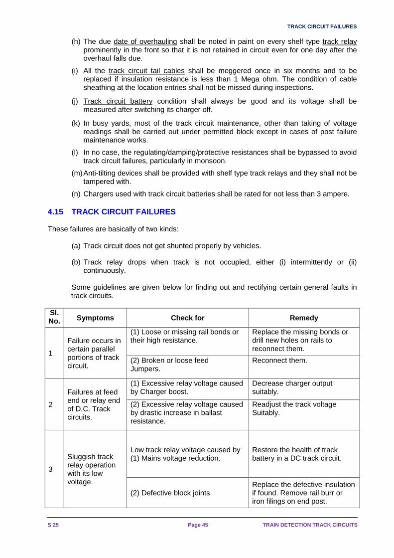
(n) Chargers used with track circuit batteries shall be rated for not less than 3 ampere. 4.15 TRACK CIRCUIT FAILURES These failures are basically of two kinds:
(a) Track circuit does not get shunted properly by vehicles.
(b) Track relay drops when track is not occupied, either (i) intermittently or (ii) continuously.
Some guidelines are given below for finding out and rectifying certain general faults in track circuits.
Sl. No. Symptoms Check for Remedy
1
Failure occurs in certain parallel portions of track circuit.
(1) Loose or missing rail bonds or their high resistance.
Replace the missing bonds or drill new holes on rails to reconnect them.
(2) Broken or loose feed Jumpers.
Reconnect them.
2
Failures at feed end or relay end of D.C. Track circuits.
(1) Excessive relay voltage caused by Charger boost.
Decrease charger output suitably.
(2) Excessive relay voltage caused by drastic increase in ballast resistance.
Readjust the track voltage Suitably.
3
Sluggish track relay operation with its low voltage.
Low track relay voltage caused by (1) Mains voltage reduction.
Restore the health of track battery in a DC track circuit.
(2) Defective block joints Replace the defective insulation if found. Remove rail burr or iron filings on end post.

TRACK CIRCUIT BONDING
IRISET Page 46 S 25
Sl. No. Symptoms Check for Remedy
(3) Defective point rodding or stretcher or other insulations (a rare occurrence)
Replace the defective insulation if found. Check carefully for any small metallic object wedged under gauge plate insulation, when relevant sleeper packing is loose
4
Track relay drops occasionally with no constant reduction in its voltage.
1) Loose or broken rail bonds Replace or reconnect the defective bonds.
2) Loose series feed jumper connections or track lead connections.
Reconnect them properly
5
Relay voltage disappears for a particular setting of points in the track circuit.
(1) Block joint or other insulation defect in the track portion connected with that point setting only.
Locate and replace the defective insulation.
(2) Loose bonding or other connections or bad jumper cable insulation in the track portion connected with that point setting.
Replace or reconnect the defective bonding or other connections and repair the defective cable.
6
Track voltage disappears soon after a vehicle movement and is restored after another movement
Defective block joint insulation over which the previous train has just passed before failure.
Replace the defective insulation
7
Track relay dropped continuously
Low track relay voltage caused by faults mentioned above.
Necessary voltage adjustments or insulation replacements or repairs to defective connections as mentioned above.
8 Intermittent dropping of track repeater relay.
(1) Low battery voltage after switching the charger off.
Replace the defective cells and boost the charger output for the time being, if necessary.
(2) Loose battery connection Remake a secure connection.
9 Continuous dropping of track relay.
Dry solder developed on shelf type track relay coil connection. Replace the relay.

VITAL SAFETY CHECKS FOR TRACK CIRCUITS
S 25 Page 47 TRAIN DETECTION TRACK CIRCUITS
4.16 VITAL SAFETY CHECKS FOR TRACK CIRCUITS:
(a) Track relay must drop when shunted by any Vehicle other than Insulated Push trolleys.
(b) For any adjustment on D.C. track Circuits , TSR Shall not be less than 0.5 Ohms.
(c) Max Excitation at Relay end shall not exceed 250 % or 300 % or 235% of its rated pickup value as per Relay type.
(d) Block Joint protecting Fouling shall not be less than 3 meters from Fouling mark. It shall be towards divergence.
(e) Staggering of polarity between adjacent rails is to be maintained. Crossing shall be maintained at negative polarity.
(f) Dead section shall not be more than 1.8m (6’).
(g) Track relays shall be located at the entry end of the train wherever feasible.
(h) Feed and relay ends shall be connected by separate and individual cables.
(i) Jumper connections shall normally so made that the whole of track circuit is in series excluding traction return rail. When the rails of a track circuit are in parallel, integrity of jumper connections to be ensured.
(j) Distance from SRJ of the loop line point to Block joint shall be 13m. The distance between this Block joint and the starter shall be 11m. Hence the starter is located at 24m from the SRJ.

TRACK CIRCUIT BONDING
IRISET Page 48 S 25
3940
4142
4344
45
STATION _________________
SIGNATURE OF S.S.E _______________
SIG
NA
TU
RE
O
F
A
.S.T
.E
CO
ND
ITIO
N
O
F R
AIL
S
UR
FA
CE
BA
LLA
ST
RE
SIS
TA
NC
ER
AIL
R
ES
IST
AN
CE
DR
OP
SH
UN
T
VA
LUE
PIC
K U
P
SH
UN
T V
ALU
E
NU
MB
ER
OF
T
RA
CK
F
AIL
UR
ES
CA
US
E O
F F
AIL
UR
ES
VO
LTA
GE
AT
R
AIL
S
VR
TIC
UR
RE
NT
AT
R
ELA
Y
TE
RM
INA
LS
RE
LAY
EN
D
3637
38
3534
3332
3130
2928
2726
2524
23B
AT
TE
RY
EN
D
CU
RR
EN
T
AT
R
AIL
S
I FF
VV
OLT
AG
E A
T
RA
ILS
WE
AT
HE
RV
OLT
AG
E
AT
B
AT
TE
RY
RE
SIS
TA
NC
E
AT
B
ATT
ER
Y
CO
ND
ITIO
N
O
F T
RA
CK
B
AT
TE
RY
CO
ND
ITIO
N
O
F
INS
ULA
TE
D
JOIN
TS
CO
ND
ITIO
N
O
F B
ON
DS
&
JU
MP
ER
CO
ND
ITIO
N
O
F R
AIL
S
UR
FA
CE
DR
AIN
AG
E
O
F T
RA
CK
G
OO
D, F
AIR
O
R B
AD
PE
RC
EN
TA
GE
O
F B
ALL
AS
T
CLE
AR
OF
R
AIL
S
CO
ND
ITIO
NS
O
F B
ALL
AS
T W
ET
D
AM
P
OR
DR
Y
DA
TE
RE
SIS
TA
NC
E O
F R
ELA
YC
UR
RE
NT
AT
RE
LAY
=V
OLT
AG
E A
T R
ELA
Y T
ER
MIN
ALS
I -
IV R
FV
RII T
T
R
1/2
(
)B
ALL
AS
T R
ES
IST
AN
CE
=V
- V
F
R
T
R
F
RV
- V
RA
IL R
ES
IST
AN
CE
=1/
2 (I
+I
)
21N
o. O
F L
.XIN
GS
IN T
RA
CK
___
____
____
____
____
___
IN T
RA
CK
___
____
____
____
____
____
____
____
___
22N
UM
BE
R O
F IN
SU
LAT
ED
JO
INTS
3D
AT
E _
____
____
____
____
____
____
____
_
P.U
. VO
LTS
___
____
____
____
____
____
____
____
___
6
D/A
. M/A
. __
____
____
____
____
____
____
____
____
__9
LEN
GT
H O
F L
EA
DS
BA
TT
. TO
TR
AC
K _
____
____
___
12
CO
ND
ITIO
N O
F S
LEE
PE
RS
___
____
____
____
____
___
1815T
YP
E O
F B
AT
TE
RY
___
____
____
____
____
____
____
_
2T
RA
CK
CIR
CU
IT N
UM
BE
R _
____
____
____
____
____
DA
TE
INS
TA
LLE
D _
____
____
____
____
____
____
___
5
P.U
. M/A
. __
____
____
____
____
____
____
____
____
_8
LEN
GT
H O
F T
RA
CK
___
____
____
____
____
____
___
11
TY
PE
OF
BA
LLA
ST
___
____
____
____
____
____
____
14
NU
MB
ER
OF
AS
HP
ITS
IN T
RA
CK
___
____
____
___
2017S
IZE
OF
CO
ND
UC
TO
R T
O R
ELA
Y _
____
____
____
_LE
NG
TH
OF
LE
AD
S R
ELA
Y T
O T
RA
CK
___
____
____
16
OR
JO
INT
S O
N A
CU
RV
E _
____
____
____
____
____
__
OT
HE
R T
HA
N J
OIN
TS A
T P
OIN
TS
19S
TA
TE O
F IN
SU
LATE
D J
OIN
TS
13LE
NG
TH
OF
LE
AD
S R
ELA
Y T
O T
RA
CK
___
____
____
10R
ES
IST
AN
CE
OF
RE
LAY
___
____
____
____
____
____
7D
.A. V
OLT
S _
____
____
____
____
____
____
____
____
_
4T
YP
E O
F R
ELA
Y _
____
____
____
____
____
____
____
_
ST
ATI
ON
OR
SE
CT
ION
OF
LIN
E _
____
____
____
____
1
Par
a 9
11(a
)A
nnex
ure
'A'
S &
T -
TC
/1
TR
AC
K C
IRC
UIT
TE
ST
RE
CO
RD
CA
RD
SIG
NA
L &
TE
LEC
OM
MU
NIC
AT
ION
DE
PA
RT
ME
NT
____
____
____
____
____
__ R
AIL
WA
Y
Fig.No.4 (A)

TRACK CIRCUIT TEST RECORD CARD
S 25 Page 49 TRAIN DETECTION TRACK CIRCUITS
45
____
____
____
____
____
__ R
AIL
WA
Y
SIG
NA
L &
TE
LEC
OM
MU
NIC
AT
ION
DE
PA
RT
ME
NT
TR
AC
K C
IRC
UIT
TE
ST
RE
CO
RD
CA
RD
S &
T -
TC
/2A
nnex
ure
'B'
Par
a 9
11(a
)
1S
TA
TIO
N O
R S
EC
TIO
N O
F L
INE
___
____
____
____
__
TY
PE
OF
RE
LAY
___
____
____
____
____
____
____
___
4
D.A
. VO
LTS
___
____
____
____
____
____
____
____
___
7
RE
SIS
TA
NC
E O
F R
ELA
Y _
____
____
____
____
____
__10
LEN
GT
H O
F L
EA
DS
RE
LAY
TO
TR
AC
K _
____
____
__13
ST
AT
E O
F IN
SU
LAT
ED
JO
INT
S19
OT
HE
R T
HA
N J
OIN
TS
AT
PO
INT
S
OR
JO
INT
S O
N A
CU
RV
E _
____
____
____
____
____
__
16LE
NG
TH
OF
LE
AD
S R
ELA
Y T
O T
RA
CK
___
____
____
SIZ
E O
F C
ON
DU
CT
OR
TO
RE
LAY
___
____
____
___
17 20N
UM
BE
R O
F A
SH
PIT
S IN
TR
AC
K _
____
____
____
_
14T
YP
E O
F B
ALL
AS
T _
____
____
____
____
____
____
__
11LE
NG
TH
OF
TR
AC
K _
____
____
____
____
____
____
_
8P
.U. M
/A.
____
____
____
____
____
____
____
____
___
5D
AT
E IN
ST
ALL
ED
___
____
____
____
____
____
____
_
TR
AC
K C
IRC
UIT
NU
MB
ER
___
____
____
____
____
__2
TY
PE
OF
BA
TT
ER
Y _
____
____
____
____
____
____
___
15 18C
ON
DIT
ION
OF
SLE
EP
ER
S _
____
____
____
____
____
_
12LE
NG
TH
OF
LE
AD
S B
AT
T. T
O T
RA
CK
___
____
____
_
9D
/A. M
/A.
____
____
____
____
____
____
____
____
____
6P
.U. V
OLT
S _
____
____
____
____
____
____
____
____
_
DA
TE
___
____
____
____
____
____
____
___
3
NU
MB
ER
OF
INS
ULA
TE
D J
OIN
TS
22IN
TR
AC
K _
____
____
____
____
____
____
____
____
_
No.
OF
L.X
ING
S IN
TR
AC
K _
____
____
____
____
____
_21
1/2
(I
+I )
RA
IL R
ES
IST
AN
CE
=V
- V
F
R
T
R
F
RV
- V
BA
LLA
ST
RE
SIS
TA
NC
E =
1/2
(
)
T
R
I -
I
VO
LTA
GE
AT
RE
LAY
TE
RM
INA
LSC
UR
RE
NT
AT
RE
LAY
=R
ES
IST
AN
CE
OF
RE
LAY
DA
TE
CO
ND
ITIO
NS
O
F B
ALL
AS
T
WE
T
DA
MP
O
R D
RY
PE
RC
EN
TA
GE
O
F B
ALL
AS
T
CLE
AR
OF
RA
ILS
DR
AIN
AG
E
O
F T
RA
CK
G
OO
D, F
AIR
O
R B
AD
CO
ND
ITIO
N
O
F R
AIL
S
UR
FA
CE
CO
ND
ITIO
N
O
F B
ON
DS
&
JU
MP
ER
CO
ND
ITIO
N
O
F IN
SU
LAT
ED
JO
INT
S
CO
ND
ITIO
N
O
F T
RA
CK
B
AT
TE
RY
RE
SIS
TAN
CE
A
T
BA
TT
ER
Y
VO
LTA
GE
A
T
BA
TTE
RY
WE
AT
HE
RV
OLT
AG
E A
T
RA
ILS
VF
FIC
UR
RE
NT
AT
R
AIL
S
BA
TT
ER
Y E
ND
23
2425
2627
2829
3031
3233
3435
4443
4241
4039
3837
36
RE
LAY
EN
D
CU
RR
EN
T A
T
RE
LAY
T
ER
MIN
ALS
I TR
VV
OLT
AG
E A
T
RA
ILS
CA
US
E O
F F
AIL
UR
ES
NU
MB
ER
OF
T
RA
CK
F
AIL
UR
ES
PIC
K U
P
SH
UN
T
VA
LUE
DR
OP
SH
UN
T
VA
LUE
RA
IL
RE
SIS
TA
NC
EB
ALL
AS
T
RE
SIS
TA
NC
E
CO
ND
ITIO
N
O
F R
AIL
S
UR
FA
CE
SIG
NA
TU
RE
O
F
A
.S.T
.E
SIGNATURE OF S.S.E _______________
STATION _________________
LOC
AL
110
V
VF
RV
RI
TR
AC
K R
ELA
Y
RE
AC
TA
NC
EA
DJU
ST
AB
LE
FE
ED
TR
AN
SF
OR
ME
R
I T
110
V S
UP
PLY
Fig.No.4 (B)
* * *

AUDIO FREQUENCY TRACK CIRCUIT
IRISET Page 50 S 25
CHAPTER – 5: AUDIO FREQUENCY TRACK CIRCUIT 5.1 INTRODUCTION Conventional D.C track circuit has certain limitati ons given below:
1. It is single rail type, i.e. only one rail is available for traction return.
2. It needs insertion of insulated block joints at all track circuit boundaries. Civil engineering department is averse to insertion of more joints as it may lead to wakening of rail and more maintenance.
3. Its working length is dependent on immunity of track relay.
4. Effect of traction harmonics generated when a thyristor controlled locomotive is worked in the track that could affect fail safety of the dc track circuit.
Signalling in auto- sections and IBS requires greater lengths of track circuit with less dependence on other departments like civil engineering, for maintenance This led to working with audio frequency, Frequency Modulated signal operated track circuit,
making a portion of track tuned to a particular frequency and matching transmitter and receivers to same modulated signal.
5.2 Audio frequency track circuits can be classifi ed into two major groups
1. Non-coded AFTC- Modulating signal is not coded. ( Pl. see Annexure) 2. Coded AFTC-Modulating signal is digital bit code d with a digital message
As bit coding of modulating signal enhances the safety, coded type track circuits are preferred over the non –coded type. This type will be discussed in detail.
5.3 As per Feeding arrangement – (a) Locally fed AFTC - In this configuration, Transmitter, Receiver, Power supplies to transmitter and Receiver and Relay, all equipments are kept on Track-side location boxes. Track repeater relay is only kept at relay room (b) Remote fed AFTC - In this configuration, Transmitter, Receiver, Power supplies to transmitter and Receiver and Relay, all equipments are kept centrally in AFTC room, while only tuning units are kept at track side box mounted on rails. The communication from transmitter to tuning unit and from tuning unit at receive ends to receiver is taken through quad cable. The 0.9 mm quad cable is best suited for impedance matching.
There are four major manufacturers of AFTC- Siemens, Alstom, ABB and US&S. while siemens and alstom AFTCs are coded type and remote fed, others are non-coded and locally fed.

CONFIGURATIONS OF AFTC
S 25 Page 51 TRAIN DETECTION TRACK CIRCUITS
5.4 CONFIGURATIONS OF AFTC
AFTC can be setup in two types.
1. END FED
2. CENTRE FED
1. End fed At one end Transmitter is provided and the other receiver is provided,
TC
Transmitter Receiver
End of Section Transmission (End Fed) Fig.1
2. Centre fed TX is provided at the centre of track circuit. RX is installed at each end of the track
TC
Receiver - II
Intermediate Transmission (Centre Fed) Fig.2
Receiver - I Transmitter
5.5 Principle of Working
a) Audio Frequency Track Circuit (AFTC) works with modulated signal in audio frequency range in Frequency Shift Keying
b) Each track Circuit, basic carrier Frequency is different from adjacent track circuit.
c) An audio frequency track circuit includes a transmitter and receiver
d) The basic carrier frequency is generated by an oscillator.
e) Oscillator is fed with D.C supply from power supply unit.
f) Power supply unit gets input 110Vor 230V AC which is converted to DC through transformer rectifier and filter circuits.
g) The modulating signals is bit coded and carries digital message selected through dip switches or jumper selection in transmitter card.
h) Transmitter card has oscillator, modulating frequency generator and modulator sections.
i) Carrier frequency and Digital data signal are fed to FSK modulator .The out put of oscillator card is modulated in the modulator.
j) The modulated output signal is fed to the primary of an isolation transformer in the tuning unit.

AUDIO FREQUENCY TRACK CIRCUIT
IRISET Page 52 S 25
k) The secondary of this transformer is connected to the R-L-C unit which forms a resonant circuit along with rails, bonds for the corresponding frequency band.
l) A portion of track thus tuned to a frequency receives maximum power from transmitter.
m) Suitable lightening protection is provided to tuning unit.
n) Screen of matching transformer is connected to earth.
o) A tuned track receiver for each section is independently tuned to the corresponding frequency Received track current signal is demodulated by the corresponding receiver and applied through decoding units to a logic network which detects track section.
p) Received signal amplitude is evaluated, frequency checked and data (coding) is checked. A relay is picked up by receiver when it measures sufficiently high amplitude of the track voltage, frequency is within the range and bit pattern data (coding) is correct
q) Modulation provides safety against interference and coding provides safety against false fed.
5.6 Understanding of coded type AFTC - FM with F SK a) FSK modulator generates output of higher frequencies and Lower frequencies with
reference to digital data signal.
b) In correspondence to each “1” bit, the “Fc+∆f” frequency (USB) is transmitted and in correspondence to each “0” bit, the “Fc-∆f” frequency (LSB) is transmitted by the FSK modulator.
c) In other words FSK modulator output is deviated between two adjacent frequencies.
d) The receiver includes a decoder tuned to the track frequency modulation rate.
e) Both frequencies are detected independently by the receiver In Frequency Shift Keying; Carrier frequency, in audio range, is generated by an oscillator and Modulating signal is digital data.
f) Carrier frequency and Digital data signal are fed to FSK modulator. FSK modulator generates output of higher frequencies and Lower frequencies with reference to digital data signal. i..e. In correspondence to each “1” bit, the “F+∆f” frequency (higher frequency) is transmitted and in correspondence to each “0” bit, the “F-∆f” frequency (lower frequency) is transmitted by the FSK modulator. In other words FSK modulator output is deviated between two adjacent frequencies.
g) Modulated signal, after amplifying and filtering, is fed to feed end of the track circuit. At the other end called receiver end / relay end this signal is taken and fed to Receiver unit in which received signal amplitude is evaluated, frequency is checked and data (coding) is checked. The receiver section only issues a ‘Track Clear’ signal if the receiver measures sufficiently high amplitude of the track voltage, frequency is within the range and bit pattern data (coding) is correct. Otherwise it shows ‘Track Occupied’ status. Modulation provides safety against interference and coding provides safety against false fed.
Fc- carrier signal in audio range
Modulating signal – Either plain square wave - in non coded type or digitally bit coded –in coded type.
∆f - Deviation frequency.

BOUNDARY BETWEEN TWO ADJACENT TRACK CIRCUITS
S 25 Page 53 TRAIN DETECTION TRACK CIRCUITS
BIT CODING
The modulating signal is digitally coded with a mes sage at a given speed
1. In correspondence to each “0” bit, the “F-∆f” frequency is transmitted and in correspondence to each “1” bit, the “F+∆f” frequency is transmitted by the MSK modulator.
H
5 ms 10 15 20 25 30 35 40 ms
bit 1 2 3 5 6 7 bit 8 bit1
Bit Pattern
Variation with time of bit pattern
4
Variation with time of modulated trackcircuit frequency
f = f + f Lf = f - f Hf = f + f
5.7 Boundary between two adjacent track circuits:
Adjacent Audio frequency track circuits are isolate d through tuning tracks to different frequencies.
1. The resonance is achieved through R-L-C circuit. These consist of a rail bond and a tuning unit. The tuning unit is located in the trackside connection box and used to tune the electrical joint to the relevant track circuit frequency.
2. Electrical isolation between two adjacent track circuits is achieved by using these tuning units.
3. Tuning unit of frequency ‘f1’ offers high impedance (pole) to its own track circuit frequency ’f1’ and low impedance (zero) to the adjacent track circuit frequency ’f3’. Similarly Tuning unit of frequency ‘f3’ offers high impedance (pole) to its own track circuit frequency ‘f3’ and low impedance (zero) to the adjacent track circuit frequency ‘f1’ as shown in fig below.
100 %
50 %
TrackVoltage
Frequency f3 Frequency f1
Response thresholdof receivers
Axle position
Shunting Overlap Zone
Track Section 1Frequency f1
Track Section 2Frequency f3
vehicle position
Track Voltage Track Voltage

AUDIO FREQUENCY TRACK CIRCUIT
IRISET Page 54 S 25
5.8 IMPORTANT FACTORS
• Balancing of traction return current -
• Traction return current in both rails is to be given a path for balancing so that there is no unbalancing in tuned zone connections.
• If the two rails are at a potential difference to each other, an unbalanced current will flow through the tuning unit which can burn the tuning unit resulting into failure.
• For balancing traction return current in tuned zone Z bond is used in TI-21, ABB AFTC, and S bond/ALPHA bond in Siemens & ALSTOM AFTC
• Avoiding interference from adjacent tracks of same frequency-
• For adjacent track circuit, same frequency or very next frequency should not be allocated. There should be at least one frequency separation. Similarly modulating signal the bit coding type can be changed with coding plug. Allocation of basic frequencies and bit coding is called frequency allocation plan.
• Fail-safety -
• Fail-safety-is dependent on correct level setting of transmitter and receiver level. Drop shunt test is done with TSR to adjust the receiver energisation level.
• In the event of over energisation caused by inadvertent change from low power mode to high power mode or by other reasons, the level of AF signal received at Rx will be beyond the specified level of demodulator and there will be neither demodulation nor detection of AF signal. This will result in the dropping of relay when the track is free.
• While shunting, the signal level is bound to come down and fall within the range of demodulation resulting in detection and output will be extended to energise the relay when the track is actually shunted.
• Hence, when adjustment in any part of the track circuit is done, all the parameters shall be checked for their correctness within the limits specified therein
5.9 AFTC installation :
(a) Installation is to be done as per installation manual of OEM (Original Equipment Manufacturer) by qualified engineers of OEM or approved agency.
(b) The railway has to prepare frequency plan and installation plans jointly OEM.
(c) Proper training of installation and maintenance staff is to be ensured.
(d) Technical and installation manuals must be given by the OEM before installations.
(e) Technical and installations manuals should detail all configurations, their installation requirements / adjustments / specified values / precautions etc for 25 KV AC RE, 1500 V DC RE and Non RE area.
(f) OEM (Original Equipment Manufacturer) should inspect AFTC installation and certify its efficacy before its commissioning.
(g) Frequency Selective Volt Meter (FSVM), True RMS multi-meter and other measuring instruments should be used for AFTC measurements.
(h) Safety tests as specified by the manufacturers like Directionality test for S bonds, Interference test, TSR tests and proper track circuit adjustment should invariably be ensured and recorded before commissioning.
(i) Provision of liners & pads under both the rails, proper drainage to avoid water logging in the track ,clearance of foot of the rails from ballast.

OUT DOOR CABLE TERMINATION
S 25 Page 55 TRAIN DETECTION TRACK CIRCUITS
(j) As AFTC is inherently a double rail track circuit, it is recommended that bonding practice should be adopted as per provisions of ACTM FOR Double Rail track circuits
(k) In case Single Rail Configuration is proposed / planned in view of RB’s letter no. 92/Sig/SGF/5-Pt dated 22.11.05, railway should ensure from the OEM that interconnection of OHE masts to rail has been assessed in its design and validated before going for it and take necessary precautions as recommended by the manufacturer.
(l) Tuning zone must not contain check / guard rails, level crossing, catch point / expansion joint, TPWS (or AWS) track equipment, impedance bonds, old bypassed insulated rail joints and structure bond / cross bond.
(m) Maximum permissible cable lengths between Transmitter (TX) & its TU (Tuning Unit) and Receiver (Rx) & its TU with 0.9 mm dia. copper conductor of quad cable are within limits as specified in technical & installation manuals of AFTC.
(n) TX and Rx of same track circuits are not run in one cable. Receivers of different track circuits having same frequency are not run in one cable. Similarly, Transmitters of different track circuits having same frequency are not run in one cable.
(o) Cable compensating resistance, line matching unit, end terminating unit, equipotential / S / α / Shunt bond etc. are used as applicable.
(p) As design of AFTC is specific to make, it would be preferable not to install variety of AFTCs in a section from maintenance point of view.
(q) At boundary of AFTC of one make with another make or DC track circuit, specified arrangement as per AFTC’s technical and installation manuals should be provided and continuity of traction return current path should be ensured and strengthened.
5.10 OUT DOOR CABLE TERMINATION
Cables for Feed –in and Feed –out : Four quad cable 0.9 mm)
Maximum Feeding : 3.5 Km Max
No of Conductors : Single pair Conductor - 1 km for TX/RX
: Double pair Conductor above 1 km for TX/RX Preparation of cable core chart:
• Separate quad cable should be used for Transmitter & Receiver irrespective of main and tail cable.
• With in a single quad individual circuits use opposite conductors i.e. 1&1 form one circuit and 2&2 form one circuit.
• Armours of each quad cable to be earthed at location boxes and at the tuning unit.
Testing of Cable:
• Minimum Insulation resistance between each pair at CT Rack should be more than 10 m ohms/km and should be recorded & maintained in the below mentioned sheet.
• Loop resistance of each pair should be recorded & maintained separately. It shall be maximum resistance of 56 Ω/Km at 20 0 C.

AUDIO FREQUENCY TRACK CIRCUIT
IRISET Page 56 S 25
5.11 Advantages of Audio Frequency Track Circuit s
1. It can be used universally in AC electrified / DC electrified / non- electrified sections.
2. Joint-Less in straight portion of tracks.
3. Dependency on other departments is minimised, as insulated rail joints are minimised for separation of track circuits.
4. Immune to harmonics - Not affected by harmonics generated by Thyristor controlled locomotives.
5. Double Rail track circuit - Both Rails are available for traction return currents.
6. Suitable for longer Length track circuits. Hence ideal for Automatic Block signalling.
7. Remote feeding up to 2.5 km possible.
8. Bit-coded Track circuit - to enhance safety & reliability
9. Uses FSK / MSK modulation for immunity against Traction interferences.
10. Diagnostic LED indications provided for ease of maintenance.
Other signals like Train speed control and messages to driver can be superimposed with train detection signal. So, it is compatible for cab signalling.
5.12 COMPARISON OF D.C. & AF TRACK CIRCUITS
Sl.No D.C.T.Cs. A.F. Track Circuits
1 These work on the principle of relay voltage regulation when vehicles shunt the track.
Only track voltage gets reduced in these when shunted to drop the relay.
2 Track Relay is required. Track Relay is not required. DC neutral line relay is used.
3 These are simple in design and less costly. These require more sophisticated and costly components.
4 They can be fed from small batteries or rectifiers connected to AC mains. Batteries need more maintenance.
Track feed is given through individual conversion units that need additional maintenance.
5 The maximum workable length of these track circuits is about 750m.
The maximum workable length of these track circuits is about 750m.
6 Insulated Rail joints at track ends are additional sources of failure in these.
Except points and crossings insulated rail joints are not used.
7 Not Immune to interference and harmonics. Immune to interference and harmonics.
8 Only one rail is available for traction return current.
Both the rails are available for traction return current.
9 Equipment is required to be provided in the trackside location box.
Equipment can be provided in centralised location.
* * *

THE GERMAN ABBREVIATION FOR FTG-S
S 25 Page 57 TRAIN DETECTION TRACK CIRCUITS
CHAPTER- 6: SIEMENS REMOTE-FED, CODED AFTC (FTG-S T YPE)
6.1 The German abbreviation for FTG-S
F = Remote fed, coded
T = Audio Frequency
G = Track Circuit
S = Siemens
TRACK
f 3
Trackside Connection boxwith tuning units
Transmitter Receiver
Indoor Equipment
Mounting frameClear /OccupiedIndication to interlocking
f 2f 1
S BONDSOut door Site
Trackside Connection boxwith tuning units
FTGS
6.1.5 System consists of the following components
(a) Indoor equipment
(b) Outdoor equipment
6.1.6 Indoor Equipment
It consists of two units:
(a) CPU (Central Processing Unit) frame with printe d circuit boards (Ref. Fig.No.5.1.a, b)
i. Transmitter card
ii. Amplifier card
iii. Filter card
iv. Receiver I card
v. Demodulator card
vi. Receiver II card
vii. Relay card

SIEMENS REMOTE-FED, CODED AFTC (FTG-S TYPE)
IRISET Page 58 S 25
6.1.1 Features of FTG-S
1. FTGS is remote fed with a frequency modulated AC voltage. Both transmitter and receiver are centrally provided in Relay Room/huts, up to 3 Km away from the track section.
2. Centralized electronic equipment consists printed circuit boards provided in frames on racks.
3. Highly reliable - since mechanical stress and climatic influences have less effect as electronic components are installed in Relay room/hut.
4. Have maximum availability since extensive operating state indications (diagnostic aids - LEDs) permit fault localisation and immediate replacement of defective PC-boards.
5. Have transmitter, receiver, and demodulation and relay PCBs of plug in type. Ten (10) FTGS track circuit components can be accommodated in a rack.
6. Maintenance free tuning units are provided in the trackside connection boxes. 6.1.2 Types of FTG-S
• FTG-S 46-suitable for longer track circuits outside station limits-4frequencies
• FTG-S 917-suitable For shorter track circuits in station limits -8frequencies
• Each frequency can have up to 15 different bit coding modulating signal.
6.1.3 Operating frequencies
FTG-S 917
F1 = 9.5 KHz
F2 = 10.5 KHz Frequency at gap of 1KHz
F3 = 11.5 KHz
F4 = 12.5 KHz
F5 = 13.5 KHz
F6 = 14.5 KHz
F7 = 15.5 KHz
F8 = 16.5 KHz
FTG-S 46
F9 = 4.75 KHz
F10 = 5.25 KHz Frequency at gap of 0.5KHz
F11 = 5.75 KHz
F12 = 6.25 KHz

TECHNICAL PARAMETERS AND DATA
S 25 Page 59 TRAIN DETECTION TRACK CIRCUITS
6.1.4 Technical parameters and data
Sl.No Technical parameters Data
1 Transmission reliability Frequency modulation coding with 15 types of 8 bit pattern per track circuit frequency
2 Minimum Ballast Resistance 1.5 ohms/km (ideal is 2.5 ohms/Km)
3 Maximum recommended TSR 0.5 ohms (other than the tuned zone)
4 Electric traction AC/DC tractions
5 Rail cross section Any
6 Power Supply (i) 220V AC + 22V/-33V, 50Hz. ±1 Hz
(ii) 110V AC ± 15%; 50 Hz ±1 Hz
7 Power Consumption
FTGS - 46 Standard Configuration (st) 80VA
Central feed-in (M) 90VA
FTGS -917
Standard (ST) 65VA
Central feed in (M) 75VA
Points (W) 75VA
Crossings (K) 85VA
8 Cable for feed in
and feed out
quad cable of 0.9 mm core diameter (from cabin to tuning unit)
Copper ropes of diameter 25 mm2 (from tuning units to track rails) 11. Diagnostic LED indications on all PCB's ensure quick fault detection 12. Comparison of transmitted and received signals using
magnetic memory in addition to electronic memory (Magnetic
memory).
9 Minimum effective length of TC 30 Mts.
10 Maximum effective: (Table - 1)
RANGES OF INFLUENCE FOR RB=1.5 OHM X KM RB=2.5 OHM X KM
FTG
S 917
REMOTE FEEDING ZA ST 917 M 917
<=1.0 OHM 350 M 950 M
<=0.5 OHM 350 M 850 M ST 917 M 917 WK 917
<=0.5 OHM 300 M 700 M 300 M 750 M YES
FTG S 46
REMOTE FEEDING ZA ST 46 M 46 ST 46 M 46
<=0.5 OHM 550 M 1000 M 750 M M
ZA = PERMITTED AXLE SHUNT ST = STANDARD LAYOUT
RB = SPESIFIC BALLAST RESISTANCE M = CENTER-FED LAYOUT
W/K = POINTS & CROSSINGS LAYOUT

SIEMENS REMOTE-FED, CODED AFTC (FTG-S TYPE)
IRISET Page 60 S 25
Mounting frame for standard track circuit (ST) or c entral feed-in (M):-
L4 L4.1
F LCRE2DE1SV
L1L7
L7
L6
L6
L5
L5
L2L3L8
L9
Fig.5.1 (a) Mounting frame FTG S 46-ST
L4 L4.1
F DE1RE2DE1SV
L1L7
L7
L6
L6
L5
L5
L2L3L8
L9
W
L6
L6
L5
L5
Fig 5.1(b) Mounting frame FTG S 46- M (b) Power supply Unit: (Refer Fig. No5.2 (a), (b))
Input voltage = 110V AC or 220 V AC
Output voltage = + 5V DC, + 12 V DC
Fig 5.2 (a) Front view
51 2 3 4 6 7 8
+ 5 V DC + 12 V DC
110 V AC Fig 5.2 (b) Rear view
AC LED TEST LED FUSES LEDLED TEST
ON SOCKET FAIL FAILON SOCKET
+ 5 V DC + 12 V DC

OUTDOOR EQUIPMENT
S 25 Page 61 TRAIN DETECTION TRACK CIRCUITS
6.1.7 Outdoor Equipment: (Fig.No5.3)
1. Tuning units in track connection boxes - 2 Nos.
2. Quad cables (9m m dia.) - for connecting T.U to Rx Tx
3. 25 mm 2 copper lead ropes - for connecting TU to rail.5.2
S BOND TRACKSIDE ARRANGEMENT.
CD B A
Connecting Box
Connecting cables
Cable Clamp
S Bond
Centre of track+ 5cm
r
Block or Branch Clamp
B
L1 L1
Lv Lv
L1
L2
rr
r
rr
D
S Bond
Fig.No.5.3 6.2.1 Principle of Working
1. Audio frequency modulated and coded signals are generated by the transmitter card.
2. These signals are amplified by the amplifier card and then filtered by the filter card.
3. The filter card passes only Fc± ∆f signals attenuates all other harmonic frequencies and noise.
4. The output of the filter card is then fed to the feed end track through a tuning unit. When the track is unoccupied, transmitted Audio Frequency modulated AC voltage reaches the receiver end tuning unit through rails.
5. From receiver end T.U. signals are sent to the receiver card provided in the cabin through quad cables. Here the signals are demodulated and evaluated in two separate channels for redundancy.
6. The codes of received signal are compared for matching with the preset code there in. If there is a match, two track relays, connected at the end of the channels in relay card (GF1, GF2) picks up.
7. Whenever the track is occupied, the transmitted signal voltages get shunted through the vehicle axle. Receiver card detects this and drops the two track relays (GF1, GF2).
8. Various LED indications are provided on each card to facilitate failure detection.
9. Various testing voltage are available at measuring sockets.

SIEMENS REMOTE-FED, CODED AFTC (FTG-S TYPE)
IRISET Page 62 S 25
Level settingand tuning
S Bonds
Track
Level settingand tuning
Filter response levelDemodulator
Amplifier Receiver 1.1 Receiver 2.1
Transmitter Receiver 1.2 Receiver 2.2
pick-up and
pick-up and
230 V AC /
Demodulator
OutdoorEquipment
IndoorEquipment
Cables
DEM
F&A* RX1
RX2 RLY
TX
DEM
from Interlocking Power Supply Interlocking
Functional Diagram of SIEMENS AFTC
1.2
1.1
to
Power Supply
12 V, 5V DC
Adjustable
Filter
Relay with
drop-out delay
Relay with
drop-out delay
Fig.5.4 (b)
6.3 Function of PCB's in FTG-S Frame
(a) Transmitter Card:
Transmitter PC board consists of a quartz oscillator with modulator. In this card a particular audio frequency voltage is generated and modulated with a bit pattern. The particular track circuit frequency is generated by means of a variable frequency divider, which steps down the clock pulses of the quartz oscillator (16,336 MHz). Bit pattern & frequency can be selected by means of bit pattern code plug and frequency code plug.
(b) Amplifier and Filter Circuits :
For FTG-S917, these are provided in one PCB and for FTG-S46, these are
on separate PCB's. In this card, the modulated audio frequency signal from the transmitter is raised to the required level by the amplifier and transmitter to the feed end point of the track via a selective filter.

FUNCTION OF PCB'S IN FTG-S FRAME
S 25 Page 63 TRAIN DETECTION TRACK CIRCUITS
(c) Receiver Circuits : These are provided on two PC Boards.
Receiver 1 PCB: It assesses the track voltage amplitude received through cable from the track-tuning unit. When the track is clear, this card transmits pulses to the demodulator card and extends DC voltage to receiver card 2.
(d) DC Modulator PCB:
When the track circuit is vacant, this card compares the bit pattern received
from Receiver 1 with an internal reference bit pattern. This reference bit pattern selected by means of bit pattern coding plug. Please note that bit pattern-coding plug of this card must have same code as in the bit pattern coding plug of transmitter card. If both are identical, the received bits are sent to the logic comparator on the Receiver 2 PCB.
(e) Receiver 2 PCB :
This card combines the output signals of receiver 1 resulting from amplitude
assessment there and those of demodulator after bit pattern check. The output signal resulting from the dynamic AND operation, is amplified and fed to the Relay PCB.
For reasons of safety, Receiver 1, Demodulator and the Receiver 2 circuits are of two identical channels picking up two relays independently.
(f) Relay PCB:
There are two relays one in each channel. The interlocking circuits regularly check the switching state of both track relays.
For operational reasons, the track occupied signal is delayed by 170 milli seconds and track clear signal is delayed by 1300 milli. Sec.
Frequency and Bit pattern (Data) coding Plugs
Different Frequency and bit pattern coding plugs are available to select the frequency and data in the transmitter card and also select the reference data signal in the demodulator card.
Frequency coding plug (for Transmitter Card only) 9500; 10500; 11500; 12500; 13500; 14500; 15500; 16500; 4750; 5250; 5750; 6250;
Bit pattern coding plug (for Transmitter Card and D emodulator Card) M2.2; M2.3; M2.4; M2.5; M2.6; M3.2; M3.3; M3.4; M3.5; M4.2; M4.3; M4.4; M5.2; M5.3; M6.2;

SIEMENS REMOTE-FED, CODED AFTC (FTG-S TYPE)
IRISET Page 64 S 25
6.4 TRACK CIRCUIT BOUND BY SECTION DIVIDER S/ALPHA BONDS
9m PTG S 469m
3.2m FTGS 9173.2m
'S' BOND OF STEELWIRE ROPE 16mm dia.IN BET. TWO AFTC'S
6.7 m FTG S 46
1.75m FTGS 917
ALFA BONDSGALVANISED STEEL WIRE ROPE 16mm dia. AT THE END OF THE AFTC
6.7 m
6.7 m
S-BOND –
1. It is a wire rope of proper cross section forming two semi loops each delimited between its center tap and its connection point to the rail. The size of S bond varies for different basic frequency.
2. This along with the rail of this track section forms the inductive branch of a parallel-resonated circuit.
3. The discrete capacitors of tuning unit make its capacitive branch.
C1 (f3)
TR
AXLE
RECEIVER (f1)
(f1) C1
TR
RECEIVER (f3)
TX (f1)
1. The more distant semi loop of the two S-bonds at the end of a track section is
tuned to the operating frequency of track circuit.
2. Feed is applied to the resonated semi loop circuit causing its transmitter to consume little energy.
3. The other semi loop of section divider is tuned to the operating frequency of adjacent track circuit.
4. Due to the layout of semi loops in the S-bond, an axle standing on the S-bond occupies both the near and advance track circuits.
5. This S-bond causes overlapping, of the two track circuits so that there is no detection gap.
In the last AFTC of a region, End bonds (Alfa bonds) are provided at their exact delimitation or for their transition to other types of track circuits with block joints in between.

MODES OF CONNECTIONS
S 25 Page 65 TRAIN DETECTION TRACK CIRCUITS
6.5 Three modes of connections are adopted for FTGS -depend on the length of section and location
(a) STANDARD LAYOUT
EFFECTIVE LENGTH
&&
SIGNALBOX
12 V DC / 5V DC 220V 50 Hz
F1F5 F3
(b) CENTRE FED LAYOUT
&&
12 V DC / 5V DC 220V 50 Hz
F1F5 F3
1 2
F1
EFFECTIVE LENGTH

SIEMENS REMOTE-FED, CODED AFTC (FTG-S TYPE)
IRISET Page 66 S 25
(c) POINT LAYOUT
&&
12 V DC / 5V D C 220V 50 H z
F5 F4
1 2
F1
F3F1
6.6 Frequency & Data (coding) allocation for SI EMENS AFTCs of one Centralised place
(a) For adjacent track circuit, same frequency or very next frequency should not be allocated. There should be at least one frequency separation. But F8 can be followed by F9 since between these two frequencies frequency separation is more.
F1 F3 201T 203T
In the above example for 202T we cannot allocate F1 & F2 frequencies. Other than those two frequencies any frequency can be allotted.
(b) If the same frequency is repeated any where in the same yard/ centralised place
then care should be taken while allocating ‘data’. Then data must be different for the other track circuit where same frequency is used.
F1 (2.2) F3 (2.4) F5 (2.2) F1 (3.2) 201T 203T 204T 205T
In the above example for 205T frequency ‘F1’ is repeated. It shall be observed that data (shown in bracket) is different for 201T and 205T.
(c) At one centralised location / station yard, for any two track circuits frequency and
data both should not be identical.

TESTING VOLTAGES AT MEASURING SOCKETS
S 25 Page 67 TRAIN DETECTION TRACK CIRCUITS
6.7 Testing Voltages at Measuring Sockets
For troubleshooting purposes, the voltage at the power unit and measuring socket the major components can be measured. The permitted values are given in the tab below.
Sockets Circuit board
Adjuster range
Permitted Value [V]
Measurement location Remarks
1/ 2 (-B40/B41-) 20V AC 9 to 12* Transmitter
output
Square wave voltage approx.18V T=1/10= 69 to 210 us
3/4 (-B42-) 200V AC 60 to 90 Amplifier output
Square wave voltage approx.100 to 150V with peaks
3 /4 (-B40-) 200V AC 30 to 100 Filter output To track (before cable
stabilizing resistor)
II 5 / II 8 II 5 / II 8 (-B33-)
20V AC > 6.5 < 5
“Clear” track volt. “Occupied” track volt.
Without external axle shunt (see section 5.10) with 0.5
I 6/II 8 II 6/II 8 (-B33-)
20V DC 12 to 15 Receiver 1 output
I 7/II 8 II 7/II 8 (-B33-)
20/2V AC 1.3 to 2.0 Demodulator input
I 8/II 8 (-B33-) 20V DC 11 to 13 12 V Supply voltage
I 9/II 8 II 9/II 8 (-B33-)
- - Receiver 1 output without modulation
I 10/II 8 II 10/II 8 (-B33-)
20V DC 5.6 Reference voltage
I 11/I 12 II 11/II 12 (-B39/B34-)
20V DC 16.5 + 1 Relay voltage
I 13/I 14 II 13/II 14 (-B39/B34-)
20V DC 4 to 5 Cascade clock pulse Output of AND element
12V /0 V 20V DC 12 + 1 Power unit Supply voltage 12V DC
5 V/0 V 20V AC 5 + 0.5 Power unit Supply voltage 5 V DC
E1/E2 (-B33-)
20/2V AC 0.3 to 2.0 Receiver 1 input Via adjusting filter;
according to setting
* Owing to shape of curve only approx. values.

SIEMENS REMOTE-FED, CODED AFTC (FTG-S TYPE)
IRISET Page 68 S 25
Restrictions & precautions
1. Frequency plan for more than two parallel tracks require interlacing of FTGS-46 and FTGS-917 AFTCs.
2. FTGS-917 has limitation of 1Km for remote feed against 2.9Km for FTGS-46 with
0.9mm dia. Copper conductor. FTGS-917 will require use of 1.4mm dia. Copper conductor for more distance.
AFTC in point zone requires insulation rail joints, strict bonding discipline. FTGS-46 configuration cannot be used in point zone. FTGS-917 is permitted for point track circuits with two receivers.
* * *

TYPES
S 25 Page 69 TRAIN DETECTION TRACK CIRCUITS
CHAPTER – 7: ALSTOM AFTC 7.1 Introduction
This system is equipped with a diagnostic board in its design and with which the values of characteristic voltages and currents can be displayed on the monitor of PC, so that they can be stored on a hard disk. 7.2 Types
DTC 24 DTC 921
F1 = 2100 Hz (diff: 400Hz) F7 = 9.5 KHz (diff: 1.6KHz)
F2 = 2500 Hz F8 = 11.1 KHz
F3 = 2900 Hz F9 = 12.7 KHz
F4 = 3300 Hz F10 = 14.3 KHz
F5 = 3700 Hz F11 = 15.9 KHz
F6 = 4100 Hz F12 = 17.5 KHz
F13 = 19.1 KHz
F14 = 20.7 KHz
DTC 24 is used for longer length track circuits, on main line, points & crossings track circuits lengths from 100m to 700m in case of end-fed configuration, and up to 1000m in case of center-fed configuration.
DTC-921- it is used for short length track circuits on main line, points & crossings track
circuits lengths from 30m to 400m.
MSK (Minimum Shift Keying)
1. The digital data is divided into even and odd stream.
2. The odd stream consists of b1, b3, b5 bits and
3. Even stream consists of b0, b2, b4, and b6 bits.
4. Each bit in both streams is held for two bits interval 7.3 EQUIPMENT
(a) Outdoor Equipment: S-bonds / α – bonds / Shunt bonds, Tuning units, cables, etc.
(b) In door Equipment- Evaluator:
(c) Tx - Rx module.
(d) RT module. (Train Detection Module)
−−−− Modem board.
−−−− Point Rx board. (for Points zone track circuits)
−−−− Diagnostic board. (Optional)
−−−− Power Supply Unit.

ALSTOM AFTC
IRISET Page 70 S 25
BLOCK DIAGRAM
110 V AC
Rx CARDTx CARD
TU TU
Filter Filter
AmpAmp
D C
RT Card
OccupiedVacant/
ComparatorDelay 2
Amp
RMS/MSR Delay 1
20 KHzGenerator
DelayNetwork
DemodulatorMSKMSK Code
GeneratorModulator
MODEM CARD
RI CARD
The connection cable between the Tuning Unit (T.U.) & processing unit used is a Shielded Cable (double armored and shielded pair plus one service telephone pair. The telephone connection can be used during calibration and putting in to service of electric joints.) Containing two conductor pairs (1 Quad) of 1.5 Sq.mm, one for each of the two track circuits of the Tuning Unit location.

WORKING OF THE SYSTEM
S 25 Page 71 TRAIN DETECTION TRACK CIRCUITS
7.4 Working of the system
1. MSK (Minimum Shift Keying) Modulation is used. This means that the digital data is divided into even and odd stream. The odd stream consists of b1, b3, b5 bits and even stream consists of b0, b2, b4, and b6 bits. Each bit in both streams is held for two bits interval. In correspondence to each “0” bit, the “f-∆f” frequency is transmitted and in correspondence to each “1” bit, the “F+∆f” frequency is transmitted by the MSK modulator. ∆f = 100 Hz. Data transmission rate is 400 Bits/ sec (Baud).
2. Digi code is fitted with a number of LED’s allowing obtaining very rapidly a rough indication of the probable origin of the problem. The signal is generated in the relay room by a modulator circuit, then amplified and injected in the track filter, a cable and a tuning unit. Receiving, tuning unit and sent to the relay room through a cable. Then the signal is filtered and checked both in amplitude and bit patterns (after demodulation) and, on the basis of the result of the checks, clear track circuit information is given.
3. At the Departure point (Exit- TX end), the code generator generates modulating signal. The modulating signal is represented by a cyclically repeated 200-bit Sequence. The bit sequence contains the protection code associated to the track circuit. The protection code is selected, via mechanically setting, while putting into service. When receiving the bit sequence, the modulator generates the MSK (Minimum shift keying) modulated signal. Then this modulated signal is power amplified, which is required for feeding to the field circuit. C1 to C42 codes are available as a modulating signal, but only 3 codes are allotted for each frequency.
4. The band pass Transmission filter is provided with passive components and transforms the square- wave signal generated by the amplifier into the sine wave signal that supplies the field circuit. After running over the field circuit, the track circuit signal returns to the Processing unit. In the processing unit, it is transformed by the vital circuits that establish the occupied / vacant state of the track circuit.
5. The band pass Receiver filter is realized by passive components and selects the track circuit signal drawn directly from the field circuit on the normal layout branch. The receiver amplifier increases the signal level so as to render it compatible with the operation of the successive circuits. The occupied / vacant state of the track circuit depends upon the effective voltage value of the signal received and upon the composition of the data message.
6. Starting from the output of the Receiver Amplifier, two separate routes can be identified. One dedicated to the valuation of the effective value and the other for comparing the message transmitted and the message received. The two routes converge in circuit, the solid-state magneto relay, which ensures a true output, when the conditions at the inputs are true.
7. The fail-safe comparator compares the demodulated data and the data transmitted by the coder on a bit-by-bit basis. The sequence compared must be in phase in order to achieve positive comparison. In order to obtain alignment, the data transmitted must be delayed for an interval of time equal to the delayed propagation of the signal via track circuits. This function is realized by the Delay network.
8. The output of the comparator supplies the delay-1 circuit that in turn enables the 20 KHz generator. The 20 KHz frequency oscillator represents one of the two inputs of the Solid State Magneto relay (RMS) / Magneto Static Relay (MSR).
9. The RMS-transfers the alternating signal from the first input to the output as and when a continuous voltage having an amplitude greater than a certain threshold present on the second input. The outgoing signal from the Receiver Amplifier is rectified to supply the RMS continuous input. The RMS threshold level is guaranteed intrinsically by its construction characteristics. The RMS output is rectified to enter into the Delay-2 circuit, the output of which generates the occupied / vacant Digi code signal.
ALSTOM AFTC
IRISET Page 72 S 25
10. The function of the Delay-1 and Delay-2 circuits is to avoid the undue temporary clearance of the track circuit ensuring, in safety, that the signal clears the track circuit only after the characteristic delay timing.
11. The comparator supplies the Delay 1 circuit. The function of this circuit is to delay the energisation of the 20 KHz generator for about 1 second only after the continuous comparison of the data transmitted and received. In addition, the delay 1 sets its output almost immediately to zero. If negative pulses of the comparator’s output are detected when the bits do not correspond.
12. The magnetic threshold supplies the delay 2 circuits. The function of the circuit is to delay for about 1 sec. The energisation of the vital output of the equipment (occupied/ vacant) after application of the 20 KHz signal and the level of the signal received at the magnetic threshold. The overall energisation delay is about 2 seconds. In case of Normal layout branch and it is 1 Sec in case of Switch branch. Moreover, the function of the delay-2 is to supply an output of zero or maximum (12V per vital input and 24V per relay coil) without intermediate values versus user.
7.5 Power Supply Unit
The manufacturer will supply the Power supply unit with the input voltage option of either 230V AC±10%, 50 Hz ±2% or 110V AC±10%, 50 Hz ±2% as per the customer requirement. 7.6 Restrictions & precautions 1. AFTC in point zone requires insulation rail joints, strict bonding discipline.
2. DTC-24 configuration cannot be used in point zone. Track circuits in point zone can have a maximum of two branches (maximum 3 receivers). For correct operation of track circuit in point zone, the length of the main branch and diverted branches are to be as specified in the manual.
3. Remote feeding with 0.9mm dia. Copper conductor is up to 3Km.
4. Tuning units are for pre-specified pairs of carrier frequencies.
5. Lengths of S-bond, Terminal bond and Short circuit bond depend upon pair of carrier frequencies used in the TU.
6. A carrier frequency can be assigned any of pre-specified 3 codes only, against a total of 42 codes.
7. Direct inter connection of OHE masts to a rail is not recommended.
7.7 Advanced features
1. Inversion of Transmitter and Receiver ends depending of Direction of Traffic.
2. Track to train message for CAB signaling in addition to train detection.

VARIOUS TEST POINTS& PARAMETERS FOR DTC 24 MAIN LIN E
S 25 Page 73 TRAIN DETECTION TRACK CIRCUITS
7.8 Various Test Points& Parameters for DTC 24 M ain Line
Card Test Points Allowed Values Measured Values
TX
CARD
V TX Square wave output. 10-90 V AC
Frequency Range at V OUT F channel ±100 Hz
V OUT TX Filter output. 2-40 V AC
DC level (50 V Fuse) 45-58 V DC
DC level (10 V Fuse) 9.0 - 11 V DC
RX
CARD
24 V DIG 22 - 28 V DC
VIN > 0.300 V AC
VRX ; when Track Circuit is Vacant 0.500 to 0.900 V AC
VRX ; when Track Circuit is Occupied 0.010 to 0.280V AC
RT CARD
+12V 11.8 -12.2VDC
-12V 12.2 to 11.8 VDC
+5V 4.9 - 5.1 VDC
24V LOC 22 - 27 VDC
OUT PUT; when Track Circuit is Vacant.
20-28 VDC
OUT PUT; when Track Circuit is Occupied.
< 0.6 VDC
OUT MSR; when Track Circuit is Vacant.
4.8 - 7 V DC
OUT MSR; when Track Circuit is Occupied.
< 4.2 V DC
20 KHZ Voltage. 25 - 32 V AC
MSR + -; when Track Circuit is Vacant.
9.8 - 20 V DC

ALSTOM AFTC
IRISET Page 74 S 25
7.9 TRACTION RETURN AND CROSS-BONDING 7.9.1 DC Traction Area
Fig. 7.9.1 (a): ALSTOM AFTC with Conventional AC Tr ack circuit
Fig. 7.9.1 (b): ALSTOM AFTC with Other AFTC (Back t o Back Terminal Bond)
Return path to Traction Sub-Station is provided through DC Impedance Bond of suitable Capacity as indicated. Connection either to power substation or to parallel tracks is realized through the center tap of impedance bonds
Fig. 7.9.1 (c): Return Path of Sub-station & Parallel Tracks
ALS
TO
M
AF
TC
Any
oth
er
ALS
TO
M
AF
TC
Any
oth
er
Impedance Bond“S” Bond
Traction Substation
Impedance Bond“S” Bond
Traction Substation
ALS
TO
M
AF
TC
AC
Tra
ck C
ircui
t
Or
Any
mak
e
Terminal Bond Impedance Bond
ALS
TO
M
AF
TC
AC
Tra
ck C
ircui
t
Or
Any
mak
e
Terminal Bond Impedance Bond

AC TRACTION AREA
S 25 Page 75 TRAIN DETECTION TRACK CIRCUITS
7.9.2 AC Traction Area
In Case of Interfacing with conventional DC Track Circuits, the Traction Return path is provided through Terminal Bond as indicated in Fig. :7.9.2(a) and in case of interfacing with any other AFTC (similar to Digi code) Fig.: 7.9.2(b) to be followed.
Fig. 7.9.2 (a): ALSTOM AFTC with Conventional DC Tr ack circuit
ALS
TO
M
AF
TC
Any
oth
erA
FT
C-c
oded
type
ALS
TO
M
AF
TC
Any
oth
erA
FT
C-c
oded
type
Fig. 7.9.2 (b): Back to Back Terminal Bond
ALS
TO
M
AF
TC
DC
Tra
ck C
ircui
t
Terminal Bond
Traction Rail
ALS
TO
M
AF
TC
DC
Tra
ck C
ircui
t
Terminal Bond
Traction Rail

ALSTOM AFTC
IRISET Page 76 S 25
7.10 Structural Bonding for Passenger Safety Running Separate earth conductor
Separate earth wires of suitable cross section are being run throughout the section and connected to the neutral (Center) of the AC Impedance Bonds spaced at every 1 – 1.5 km distance. Refer the following figure.
Structures of OHE connected to one Rail uniformly.
In this case, the broken rail detection for the traction rail (on which the structure bonds are connected) is not assured. The reduction in track circuit length is to be analyzed. Refer the following figure.
Permitting One Structure Bonding Per Track Circuit
In such arrangement, only one OHE structure is allowed to be connected to either of the Rail Uniformly as indicated below.
* * *
DN
f1 f3 f5 f1
Structure Structure Structure Structure
Structure
f5 f3
TU f1/f3 TU f3/f5 TU f5/f1 TU f5/f1 TU f1/f3
Structure Structure Structure Structure Structure
DN
f1 f3 f5 f1
AC IMP.Bond (CI300) 1.0 to 1.5 km
Structure
Earth Return
Structure Structure Structure Structure Structure Structure Structure
Structure
f5 f3
TU f1/f3 TU f3/f5 TU f5/f1 TU f5/f1 TU f1/f3
DN
f1 f3 f5 f1
Structure Structure Structure Structure Structure Structure Structure Structure
Structure
f5 f3
TU f1/f3 TU f3/f5 TU f5/f1 TU f5/f1 TU f1/f3

INTRODUCTION
S 25 Page 77 TRAIN DETECTION TRACK CIRCUITS
ANNEXURE – I
ABB – AUDIO FREQUENCY TRACK CIRCUIT – STYLE TI –21
(a) The transmitter feeds in the AF voltage to the track through tuning unit, which is received at the other end by the receiver. The Receiver directly operates a standard miniature line relay.
(b) The track circuit operates on a frequency shift principle where the basic frequency is shifted between two frequencies close to each other (+ 17 Hz & - 17 Hz). Both the frequencies are detected independently by the receiver for energising the track relay.
(c) This modulation is made to enable transmission of Audio Frequency without getting distorted.
(d) There are eight nominal frequencies (A to H) in the range of 1.5 KHz. to 2.6 KHz that are employed to have eight types of track circuits.
(e) This enables two types to be used per track and with the available eight types track circuit requirement of quadruple lines can be met.
F2Rx
RelayTrack
F1Rx
24 V DCPSU
F2Tx
RelayTrack
24 V DCPSU
F1Tx
TRACK CIRCUITFREQUENCY
F1F1FREQUENCY
TRACK CIRCUIT
F2FREQUENCY
TRACK CIRCUIT
TUF1 F2
TU TUF1F2
TU
Fig.No.7.1
Block Diagram of a Basic Audio Frequency Track Circ uit 2. ELEMENTS OF AFTC
Sl. No. AFTC consists of No.s
(a) Transmitter 1
(b) Tuning Unit 2
(c) End Termination Unit 1 (In centre fed Track Circuit only)
(d) Receiver 1
(e) Power Supply Unit 2
(f) Output Relay 1

ANNEXURE – I
IRISET Page 78 S 25
3. Transmitter – TX
(a) A Bi-stable Multi-vibrator (1) produces a square wave output of 4.8 Hz. An oscillator
(b) Produces the nominal frequency f (A or B or H).
(c) The square wave output of the multivibrator modulates the output of oscillator (f) to produce a signal, which varies by ±17 Hz about the nominal frequency (f) at a rate of 4.8 Hz in modulator
(d) The output amplifier (4) increases the signal to a power level suitable for transmission down the track. The transformer (5) provides a means of matching the amplifier output to the load. Filter (6) is provided to isolate the unit from unwanted AC / DC currents from the track.
Functional diagram of transmitter is shown below: -
4
2
1
3
TransformerMatching / Isolating
65
To Tu
AmplifierOutput
llatorOsci-
OutputFilter
Modu-latorVibrator
Multi
Fig.No.7.2
The transmitter output waveform is shown below: -
f - 17f + 17f - 17f + 17
Modulation at 4.8 HZ
Fig.No.7.3

RECEIVER - RX
S 25 Page 79 TRAIN DETECTION TRACK CIRCUITS
4. RECEIVER – RX
Functional diagram of Receiver is shown below: -
1
7
6
2b 3b 4b 5b
5a4a3a2a
formerTrans-Input
From TuInput
RelayOutput
DriveRelay
DelayTime
DemodulatorFilter
Amplifier
Filter
DemodulatorFilter
AmplifierFilter
AND Gate
Sequential
Fig.No.7.4
1. Signal received from the (receiver end) tuning unit is fed to the Input-Isolating
Transformer (1) of the Receiver.
2. This has tappings to obtain different turn ratios for the adjustment of receiver gain. Inter-winding earth screen is provided to afford protection from the common mode interference’s.
3. Different taps as provided on the input side to be connected to the tuning unit are shown ' below. The connected tap is for a gain of 7.
4. Receiver input wiring & pick up current for different gain settings are given in Annexure I. 1Ohm resistance is provided to enable direct measurement of input current.
ETU/TTUFrom
I/P1
I/P2
I/P2
1
3
9
1
9L
9H
3L
3H
1L
1H
Terminal arrangement of Receiver for Gain Adjustment
Fig.No.7.5
The higher frequency of signal is filtered at 2A and the lower frequency of signal at 2B. Thereafter, they are amplified at amplifiers (3A & 3B), filtered at (4A & 4B) and demodulated at 5A & 5B. The two demodulated frequencies are combined in a sequential 'AND' gate (6) which give a constant output only when both the frequencies are out of phase by 180 degrees. This output after an initial time delay of about two seconds provided by (7) is extended to the relay driver to energise the relay.

ANNEXURE – I
IRISET Page 80 S 25
5. Track Tuning Unit - TTU
The electrical separation of adjacent track circuits is obtained by tuning a short length of track (about 20 meters) using tuning units to which a transmitter/receiver is connected. Each tuning unit present offers low impedance to the frequency of adjacent track circuit and prevents its influence. Thus tuning unit forms a part of electrical separation joint. Block schematic of the tuning unit is given below:
TO TRACK
TUNING UNIT
MODETo Tx - HIGH POWER
Tx - LOW MODETo Rx - BOTH MODES
5
1
C2
432
C1
T1
T2
L
Fig.No.7.6
Tuning unit, in addition to acting as a selective band pass filter provides a means of connecting transmitter/receiver to the rails. Receiver is always connected to terminals 1 & 2. Transmitter is connected to terminals 4 & 5 for normal power mode while it is connected to terminals 1 & 2 for low power mode (short track circuits of 50 to 250 m.) 6. End Termination Unit - ETU
End Termination Unit is used at the start and the end of section on which AFTC is provided. An insulated rail joint is normally provided beyond the ETU within one meter. It is also used in place of TTU for centre fed arrangement. Two types of end termination units - one with 3 parallel branches of circuits for frequencies A, C, E & G and the other with two branches of circuits, for frequencies B, D, F & H. The schematic arrangement of each is given below:
FREQ - B,D,F,HFREQ - A,C,E,G
Rx
TO TRACK
TO TRACK
Tx
ETHETH
Tx
TO TRACK
TO TRACK
Rx
END TERMINATION UNIT
Fig.No.7.7
A common power supply unit feeds 2 adjacent AF Track circuits.
7. Output Relay: 50 V / 1350 ohm, DC neutral relay to BRS: 930.

TECHNICAL SPECIFICATION OF AFTC
S 25 Page 81 TRAIN DETECTION TRACK CIRCUITS
8. TECHNICAL SPECIFICATION OF AFTC
1. Track circuit length
a) End Fed Low mode 50 - 250 metres
Normal mode 200 - 650 metres
b) Centre fed 450 - 1200 metres
2. Minimum ballast resistance 2 OHM / km
3. Minimum Train shunt resistance 0.5 ohm (outside tuned area)
0.15 ohm (inside tuned area)
4. Boundary of track circuit +/- 5 metres (max.) (from centre of tuned area)
5. Length of electrical separation Joint 18.0 - 22.0 metres.
6. Output relay 50 V / 1350 ohm. DC neutral relay to BRS: 930.
7. Track circuit Frequencies:-
Type Nominal Frequency Actual Frequency band
Lower Limit Upper Limit
A 1699 Hz. 1682 Hz. 1716 Hz.
B 2296 Hz. 2279 Hz. 2313 Hz.
C 1996 Hz. 1979 Hz. 2013 Hz.
D 2593 Hz. 2576 Hz. 2610 Hz.
E 1549 Hz. 1566 Hz. 1532 Hz.
F 2146 Hz. 2163 Hz. 2129 Hz.
G 1848 Hz. 1865 Hz. 1831 Hz.
H 2445 Hz. 2462 Hz. 2428 Hz.
8. Current consumption on 24 V DC side
Transmitter 2.2 A (Max)
Receiver 0.5 A (Max)
9. Transmitter power output (max) Low Mode 3 W
Normal Mode 40 W
10 Maximum length of connecting cable between
a) Transmitter & feed end tuning unit 30 meters
b) Receiver & Receiver end tuning unit
350 meters
11 Receiver output 40 V - 65 V DC
12 Receiver Sensitivity 15 Ma
13 Maximum length of cable (19/1.8 mm Sq. Al.) between the tuning unit and track
Long Cable 3.25 M.
Short Cable 1.45 M.

ANNEXURE – I
IRISET Page 82 S 25
14 Resonated impedance bond
Resonated impedance 12 ohm (Min.)
Traction impedance DC 0.75 m Ohm AC 3.00 m Ohm
15 Power Supply Unit
Input (Nominal) 110 V, 50 Hz
Input tappings 5 - 0 - 95 - 105 - 115 V
Output voltage 22.5 to 30.5 V DC
Output current 4.4 A (Max.)
Ripple Content 3 V peak to peak
9. Centre fed arrangement
When the length of track circuit is required to be more than 900 meters, centre fed arrangement shall be provided as indicated below:
T2
2TT1
ETU 2
Tx 2
3TU
3Tx2Rx R2RR
3TUR
2RL
2TUL
2RxL
1TU
Tx1
CENTER FED TRACK CIRCUIT
Fig.No.7.8 10. Termination with other types of Track Circuits
A special arrangement using ETU shall be provided as indicated below when an AFTC is followed by other types of track circuits. Insulated rail joints are, to be provided at a distance not greater than 1 meter.
TERMINATING WITH OTHER TCs
< 1 M
OTHER TCAFTC
RRx
ETU
Fig.No.7.9

TERMINATION OF AFTC WITH NON- TRACK CIRCUITED PORTI ON
S 25 Page 83 TRAIN DETECTION TRACK CIRCUITS
11. Termination of AFTC with non- track circuited portion
Both the rails are to be shorted with 50 sq. mm Aluminium cable at 18.5 meters from the last tuning unit as indicated below:
INTERFACE WITH NON-TRACK CIRCUITED LINE
TTU
Rx R
18.5 M
Fig.No.7.10 12. Frequency allocation plan In this AFTC Type TI 21there are Eight Operating Frequencies A to H.
A & B - Paired Frequencies for FIRST Line
C & D - Paired Frequencies for SECOND Line
E & F - Paired Frequencies for THIRD Line
G & H - Paired Frequencies for FOURTH Line
For more than four tracks the above sequence is repeated. Between track-circuits of same frequency pair on different Lines, there should be a minimum separation of two lines

ANNEXURE –II
IRISET Page 84 S 25
ANNEXURE - II
AFTC - UM71 (UNION SWITCH & SIGNALS)
1. Brief description The UM71-AFTC is a Non-coded, remote feeding upto 1 KM.
2. 5. Principle of operation Frequency assignment The UM71 operates at one of the four basic carrier frequencies in two pairs: CARRIER FREQUENCIES Fc SET1 (UP LINE) * One pair assigned to Track I: V1-F1 : 1700Hz
V1-F2 : 2300Hz CARRIER FREQUENCIES Fc SET2 (DN LINE) * One pair assigned to Track II: V2 - F1: 2000Hz
V2 - F2: 2600 Hz Each pair (set) can be used for one track (UP / Dn.)
This Track Circuit operates on Frequency shift key (fsk) principle where the frequency is shifted between two frequencies close to each other (i.e. Basic frequency ± 11 Hz).
∆ F = 11Hz Modulation rate is set by division of 128 of the basic frequency. Fc
i.e. modulation signal frequency = 128
Example: -
CARRIER FREQUENCIES Modulation Rate
V1 - F1 - 1700 Hz 1700/128 = 13.3 Hz
V1 - F2 - 2300 Hz 2300/128 = 18.00 Hz
V2 - f1 - 2000 Hz 2000/128 = 15.6 Hz.
V2 - f2 - 2600 Hz 2600/128 = 20.3 Hz
6. Components
The system consists of the following components:
(a) Indoor equipment. (Equipment at Relay room)
(b) Field Equipment (wayside equipment)

INDOOR EQUIPMENT
S 25 Page 85 TRAIN DETECTION TRACK CIRCUITS
(a) Indoor Equipment
The Equipments in the Relay room are Transmitter, Receiver, Power supply unit and Relay (24 V DC plug-in-type Relay).
(i) Transmitter (Tx)
The transmitter generates a power limited sinusoidal signal, at one of the four basic frequencies (Fo) 1700 Hz; 2000 Hz; 2300 Hz; 2600 Hz.
The basic frequency is encoded by shifting which is switching two frequencies with a modulation depth, ∆∆∆∆ ƒƒƒƒ = 11 Hz. The basic frequency is modulated at a rate set by division by 128 of this basic frequency (Fo).
(ii) Receiver
The Receiver detects the presence of the train in the associated track section. The receiver must recognise the carrier signal in quality (modulated frequency) and in quantity (i.e., level).
(iii) Relay
It is a 24V DC, plug-in-type, non-proved type. (Ordinary Q series line Relay QN1 can be used as a Track Relay).
(b) Field Equipment (way side equipment)
The Air core Inductor (ACI), Matching Unit (MU) and Tuning Unit (TU) are
provided at the way side, near the tracks. There is one tuning unit (TU) for each of the four frequencies used, where as matching unit is common for all the frequencies.
(i) Matching Unit (MU):
Impedance matching between the items of the equipment installed at the
track and those installed in the technical room (i.e. Relay room - Tx and Rx) is achieved by means of an auto-matching unit.
(ii) Tuning Unit:
There are two types of tuning units: -
- Tuning Unit F1 (V1 & V2): This consists of LC (inductive Capacitance) series circuit tuned at a frequency close to F2. If characteristics are:
Capacitive impedance at frequency F1
Low capacitive impedance at frequency F2
- Tuning Unit F2 (V1 or V2): This consists of a LC series circuit, tuned at a
frequency close to F1, mounted in parallel with a high value capacitor. Its characteristics are
Low capacitive impedance at frequency F1, with the parallel capacitor
shorted by the series branch tuned at F1.
Capacitive impedance at F2, resulting from the tuning of the three components. As frequency F2 is higher than frequency F1, the inductive series tuning is marked by the parallel capacitor.

ANNEXURE –II
IRISET Page 86 S 25
FOR TRACK 1 FREQUENCY PAIR:
V1 F1 TU : Exhibits ‘ ZERO’ at 2300 Hz ( V1– F2) &
‘POLE’ at 1700 Hz (V1– F1)
V1 F2 TU : Exhibits ‘ ZERO’ at 1700 Hz (V1– F1) &
‘POLE’ at 2300 Hz (V1– F2)
FOR TRACK 2 FREQUENCY PAIR:
V2 F1 TU : Exhibits ‘ ZERO’ at 2600 Hz (V2 – F2) &
‘POLE’ at 2000 Hz (V2 – F1)
V2 F2 TU : Exhibits ‘ ZERO’ at 2000 Hz (V2 – F1) &
‘POLE’ at 2600 Hz (V2 – F2) (iii) Air Core Inductor (ACI):
There are two types of ACI. They are:
- The ACI 200 - used for re-equalizing the traction current.
- The higher power ACI 600- used for routing the traction return current.Electrical Separation Joint (ESJ):
1. For implementation of continuous track circuits, reliable separation of audio
frequencies on all continuous track circuits (common to same ESJ). This can be achieved either conventionally through the use of insulated joints which break the rail electrical continuity or through electrical separation joint, which do not require any continuity bonds. The ESJ consists of a short track section limited at each end by a LC-type tuned circuit, known as TU. And on Electrified track, a non-saturable inductor, known as the ACI, is located at the centre of the ESJ. ESJ length varies from 20 to 29 meters in accordance with Rail type, Sleepers type, Track gauge, Track electrified or non-electrified. Cables: 1. PSU to Tx/Rx Flexible 1 sq.mm.
2. Tx/Rx to TMU Quad cable - 0.9 mm dia
3. TMU to Rail 70mm2 copper or 120 mm2 Aluminum

PARAMETERS
S 25 Page 87 TRAIN DETECTION TRACK CIRCUITS
Parameters:
At PSU Input voltage 110VAC ± 25%
Output voltage 24VDC ± 1V
At Tx (KEM) Input voltage 24V DC ± 1V
Output voltage 25 to 50 V AC
Frequency 2300 Hz ± 3 Hz
Gain adjustment (V1 - V10) V5 to V6 - 3Units
At TMU (Tuning & Matching Unit) (Tx end)
Input at E1 & E2 25 to 50VAC
Frequency 2300 ± 3 Hz
Output of TMU 1V to 5VAC
Input across the track 1V to 5VAC
At TMU (Rx end) Voltage across the track (ie. Input to TMU at Rx end)
0.2 to 0.8 VAC
Output of TMU (Rx end) 0 to 3VAC ie. V1 - V2
At RX (KRV) Input to RX (v1 - V2) 0 to 3V AC
Voltage at R1 R2 > 250mv AC
Gain adjustment (R3.... R10) KRV56
At KRV
K= adjustment
RV = Rx Input.
PU. TSR 1 Ohm.
Drop TSR 0.5 Ohms
KRV 56
At TR Voltage across the TR without T.S.R
24 to 30VDC
Voltage across the TR with 0.5 Ω TS.R
0V DC
* * *

ANNEXURE –III
IRISET Page 88 S 25
ANNEXURE – III
AC. TRACK CIRCUITS 3.1 A.C.Track Circuits are provided where D.C. Track circuits cannot work. The working of an AC Track relay requires not only a good voltage from the track but also a considerable phase difference in track voltage with reference to the voltage applied to one of the relay windings locally. Even as a good phase difference is maintained at the track feed end, it gets reduced at the relay end due to the transformers, impedance bonds, relay winding and the ballast resistance in the circuit. Also, the phase angle gets shifted when the ballast resistance changes according to weather. These effects create problems for efficient and safe maintenance of the track circuit. Hence A.C. Track Circuits are provided exclusively in DC traction areas confined to Bombay Divisions of Western and Central Railways. It is possible to work A.C. Track circuits with A.C. traction also, provided the track circuit supply frequency does not have even a harmonic relation with the traction power frequency of 50Hz. 83 1/3 Hz frequency is chosen for this purpose and these track circuits are used in A.C.Traction areas including the places where DC electric traction ends and AC traction starts.
In areas of exclusive AC traction of our railways, the usage of AC track circuits is tried out for some time due to the tempting possibility of working very long AC track circuits. However, this practice is not continued for long there, due to the problems in maintaining a good phase angle on these track circuits. DC track circuits are preferred there now.
Introduction of electronic track circuits of high impulse type and audio frequency type on our railways created prospects for gradual and widespread replacement of many conventional DC and AC track circuits.
AC and Electronic track circuits in RE areas can be broadly classified as (1) Single Rail track circuits and (2) Double Rail Track Circuits conventional AC track circuits of both the types are dealt with here.
Single Rail track circuits as already seen in the case of DC track circuits in AC RE area,
are those in which traction return current also passes through one of the two track circuit rails. In these the traction return current passes from one track circuit to another through transverse bonds provided by the traction power department.

SUPPLY ARRANGEMENTS FOR TRACK CIRCUIT FEEDING
S 25 Page 89 TRAIN DETECTION TRACK CIRCUITS
Double Rail track circuits are those in which the traction return current passes (in the same direction) through both the track circuit rails (even as the track circuit current passes in the same direction in one rail and in the opposite direction in the second rail). Traction return current from both the track circuit rails passes into the adjoining rails through the centre tap of an 'impedance bond' provided by the S&T department. But the track circuit current is confined within its limits by the block joints provided on both the rails at its ends. Most of the current from the feeding transformer flows through the relay and the ballast, even though small leakage currents through the impedance bonds cannot be avoided. British practice of AC track circuits which was initially followed on the Bombay divisions of Western and Central Railways has given way to the Siemens practice as progressively Siemens installations have been introduced there. As Railways switched over to AC. traction, Siemens practice is the only prevailing one on our railways at present. Hence, our study will be confined to this. 3.2 SUPPLY ARRANGEMENTS FOR TRACK CIRCUIT FEEDING
A reliable 3 phase AC supply is a pre-requisite for working AC track circuits in Siemens practice. All the track relays are fixed in the cabin relay room.
In DC traction areas, a 440/110-130V transformer is provided in the cabin for this purpose. A 3 phase 130V 50Hz output from this transformer is taken on a ring main busbar to the track relay racks.
Where 83 1/3 Hz AC. track circuits are provided 440V 3 phase 50Hz AC supply is fed into a frequency convertor (preferably static). 165V 83 1/3 Hz 3 phase output from this converter is taken to the track relay racks in the relay room.
Another 110V 3 phase feed is taken as output from the transformer or inverter, as the case may be, and fed to a ring mains busbar taken to various location in the yard for track circuit feeding.
'Track feed phase distribution plan' for the yard is prepared well in advance to nominate phases between which individual track feed transformer connections at site and their corresponding relay local coil phase connections in the cabin are to be made.
While making this plan, (i) load on each phase is sought to be balanced as far as possible and (ii) Staggered phase connections are made on adjacent track circuit rails to avoid unsafe conditions at the time of block joint failures.

ANNEXURE –III
IRISET Page 90 S 25
3.3 A.C SINGLE RAIL TRACK CIRCUIT
110V 50 Hz AC supply or 110V 83 1/3 Hz AC supply between the nominated phases in the location box is connected as input to the track feed transformer for stepping down. l Its output from a suitable tapping on its secondary is taken with a 3 Ohm damping resistance in series to the track lead J.Box or Bootleg on a 2 core cable of 1.5 mm2 or 2.5 sq. mm copper conductors. Multistrand wires ropes connect the feed to the track rails.
At the relay end, track leads are taken similarly to the J.Box or bootleg. From these, a 2 core 1.5 mm2 cable takes this feed to the relay end step up transformer with a 2 ohm protective resistance in series. From the secondary of this transformer feed is taken on a common cable from location to the cabin to be connected there to the relay control coil.
The relay local coil is connected in the cabin between the nominated phases of the ring main busbar of 130V 50Hz or 165V 83 1/3 Hz, as the case may be . At the end of this track circuit a transverse bond is connected by the traction power department if there is a track circuit or there is no track circuit on the adjoining rails. If there is a double rail track circuit adjacent to this, a multistrand wire rope known as neutral connection is joined between the uninsulated rail of this track circuit and the centre tap of impedance bond by the side. 3.4 IMPEDANCE BOND
It is a device used for bonding the rails of a Double Rail track circuit with adjacent track rails for the purpose of conducting traction return current while blocking the track circuit current to pass within its relay circuit. The construction of an 'impedance bond' is as given below :-

IMPEDANCE BOND
S 25 Page 91 TRAIN DETECTION TRACK CIRCUITS
There are two copper coils in the bond wound on a shell type core. One is called the 'Main or Buffer coil' which consists of about 8 to 10 turns of a heavy cross section. This carries the large traction return current when connected between adjacent rails across block joints at the end of a track circuit.
The second winding is called as the 'Auxiliary Coil' which has a large number of turns of a smaller cross section with different tapping for connection. This windings is used along with a 10 µf condenser to resonate the output circuit. This circuit resonation makes it possible to draw maximum current from the given input voltage and improves the output phase angle also. A surge anestor is also connected to protect the condenser in the auxiliary coil. Higher inductance of the auxiliary coil having many turns facilitates the usage of a small condenser.
The impedance bond coils are included in the track circuit with a transformer type connection. At the track circuit feed end, the auxiliary coil with the condenser in series acts as the primary circuit to draw power from the track feed transformer secondary. Hence, the series resonating Condenser also serves as the 'Regulating Device' for dropping a large voltage across it under track occupation. The main coil acting as the secondary steps down the feed voltage to less than 5V on open circuit and feeds it to the track rails when connected across them.
At the relay end of track circuit, the track rail voltage gets impressed on the main coil of the bond which form the primary. On the secondary side, the auxiliary coil steps up the voltage to over 25V and feeds the relay control coil. On the relay end impedance bond, a 10 µf condenser is connected in parallel on a carefully chosen tapping of the auxiliary coil. This condenser is known as the 'phase shifting condenser' as it serves to improve the output phase angle of the bond so that the relay rotor gets the best possible torque, by the choice of right tapping on the auxiliary winding for its connection.

ANNEXURE –III
IRISET Page 92 S 25
3.5 FLUX SYSTEM IN THE BOND CORE
AS can be seen from the diagram, half the number of turns in the bond main coil carry traction return current in one direction and the other half in opposite direction. Due to these currents, the fluxes established in the core are in opposite direction. They are also equal if both the rails carry equal current to the bond. In that case, no flux due to traction return current remains in the core. Hence, when track circuit current tries to pass through all the coil turns in the same direction a very high inductance causing reactance of the order of 3 Ohms or more is encountered by this current. A very low current only can leak through this path while sufficient current passes through the relay coil in parallel and operates it. 3.6 EFFECT OF UNBALANCED TRACTION RETURN CURRENTS T HROUGH BOND IN DC RE AREA Due to some loose bonding on one of the rails or some such reasons, if traction current through the rails is unequal, bond core retains the difference of fluxes due to the unbalanced traction return currents. This can saturate the core if the retained flux rises to a high level. Such a condition may occur when a train is started in approach of the track circuit.
In saturated condition of the bond core, the track circuit current through bond coil encounters a very negligible inductance as it cannot create any further flux in the core. This causes a heavy leakage current through the bond coil making the track relay to drop.
To obviate this, saturation of the core by unbalanced traction currents in the bond coil is prevented by increasing the core reluctance. This is done by means of a thin sheet of nylon on the core limbs above as shown in the diagram.

IMPEDANCE BOND IN AC.RE AREA
S 25 Page 93 TRAIN DETECTION TRACK CIRCUITS
3.7 IMPEDANCE BOND IN AC.RE AREA (1) The Impedance bonds in AC. RE area carry lesser traction currents due to higher voltage of 25 KV as against 1500V of DC used for traction. Because of this, the cross section of the main coil conductor required is less and hence these bonds are smaller. (2) Due to the higher frequency of track circuit current used in this area (83 1/3 Hz instead of 50Hz) the impedance of the bond increases to nearly 5 Ohms from about 3 Ohms of those in D.C traction. (3) No provision of nylon sheet in the core for increasing its reluctance is required in these bonds as core does not get saturated by the traction currents. The reason for this is that the traction currents through the two halves of the bond main coil exhibit a self balancing features as explained below:- When unequal currents flow through the two half windings of the bonds main coil, unequal fluxes are created in the core by these. But since traction current is AC and the flux created is alternating, back emf's are induced in the two half coils in such a manner that the currents balance themselves out.
Fig.No.3.8(a)

ANNEXURE –III
IRISET Page 94 S 25
3.8 AC DOUBLE RAIL TRACK CIRCUIT
A 110/25-75V step down track feed transformer draws its input from two nominated phases of supply in the location box. Its secondary output is taken on a cable to the impedance bond provided on the track at feed end. The supply is connected to suitable tapping on the auxiliary coil of the bond with the 10 µf regulating condenser in series. The main coil of the impedance bond is connected across the track rails with two multistrand steel wire ropes known as 'side connections' of the bond. The voltage is stepped down on the bond at the feed end. The center tap of the bond main coil is connected to the adjoining track circuit by means of a 'neutral connection' wire rope. At the relay end of the track, the main coil of another impedance bond is connected across the rails to draw about 1V from the track. This will be stepped up suitable on the auxiliary coil of the bond. Also, the phase angle of this voltage gets corrected as required by the connection of 10 µf bond condenser on suitable tapping of its auxiliary coil. This output voltage at a phase angle above 60
o with respect to source is fed to the relay end track lead cable on the bond which is laid upto the cabin relay room. This voltage is applied to the track relay control coil. The relay local coil is connected on the rack to nominated phases of local supply.
At the relay end also, the center tap of impedance bond main coil is joined with the adjacent track circuit.
In all the AC track circuits, a voltage between 130% and 200% of relay safe pick up value is maintained on the control coil of the relay. The local coil voltage is 130V @ 50Hz or 165V @ 83 1/3Hz as already mentioned. A phase difference of 60o – 90o is to be maintained between the control coil and local coil voltage of the relay for reliable working of the track circuit. A minimum T.S.R of 0.15 Ohm is permitted to be maintained on these track circuits. Whereas a good T.S.R can be easily obtained on a single rail track circuit, it requires careful adjustment of track voltage and phase angle on the double rail track circuit to get the required minimum T.S.R of 0.15 Ohms.
* * *

COMPARISON OF VARIOUS AFTCS IN USE OVER INDIAN RAIL WAYS
S 25 Page 95 TRAIN DETECTION TRACK CIRCUITS
ANNEXURE - IV COMPARISON OF VARIOUS AFTCS IN USE OVER INDIAN RAIL WAYS
FEATURES ABB -TI-21 US&S-UM-71 SIEMENS-FTGS ALSTOM- DTC-III 1 Basic Frequencies (Fc) A-H( 8 frequencies) 4 frequencies FTGS-46 (4 frequencies) DTC-24-( 6 frequencies)
A-1699 Hz., B-2296 V1F1-1700HZ, 4.75KHZ, 5.25 KHZ 2.1KHZ, 2.5 KHZ, 2.9KHZ C-1996 ,D-2593 V1F2-2300HZ 5.75KHZ, 6.25 KHZ 3.3 KHZ, 3.7KHZ, 4.1 KHZ E-1549, F-2146 V2F1-2000HZ, Separation 0.5KHZ Separation 0.4KHZ G-1848 ,H-2445HZ V2F2-2600HZ FTGS-917 (8 frequencies) DTC-921 – ( 8 frequencies) 9.5 KHZ,10.5 KHZ,11.5 KHZ 9.5 KHZ,11.1 KHZ, 12.7 KHZ,
12.5 KHZ,13.5 KHZ,14.5 KHZ 14.3 KHZ, 15.9 KHZ,17.5 KHZ, 15.5KHZ,16.5KHZ 19.1 KHZ,20.7 KHZ (Separation-1 KHZ) (Separation-1.6 KHZ)
2 Modulating Frequency(Fm) 4.8 HZ F/128 HZ 200 BPS-15type 8bit message 400 BPS 3 Deviation Frequency(+/-f) 17 HZ 3 HZ 64 HZ 100 HZ 4 Modulation FSK FSK FSK MSK 5 Coded or not Non-coded Non-coded Coded Coded 4 Remote Feeding 1 KM 1 KM 2.5 KM 3.5 KM 6 Bonds Used at boundary Z -bond Air core inductor S-bond, alpha, S-bond, alpha, double alpha 7 Interfacing With Non-TC area Shunt Bond Shunt bond Shunt bond Shunt bond 8 Number of Lines Four Two Any Any 9 Compatibility to cab signalling No No Yes Yes 10 Card File TX,RX,PSU TX,RX,PSU TX,RX-I,RX-II,PSU TX,RX,RT 11 Relay 1000-OHM-QS3 1000-OHM-QS3 Miniature Miniature 12 Overlap Zone 22 m 5m 5m 13 Minimum Length 50 m 50 m 30 m 30m
14 Maximum Working Length
(A) End Fed 450 m 450 m 450m 450m (B) Centre Fed 700 m 700 m 700m 700m
15 Diagnostic Nil Nil LED indications Diagnostic card
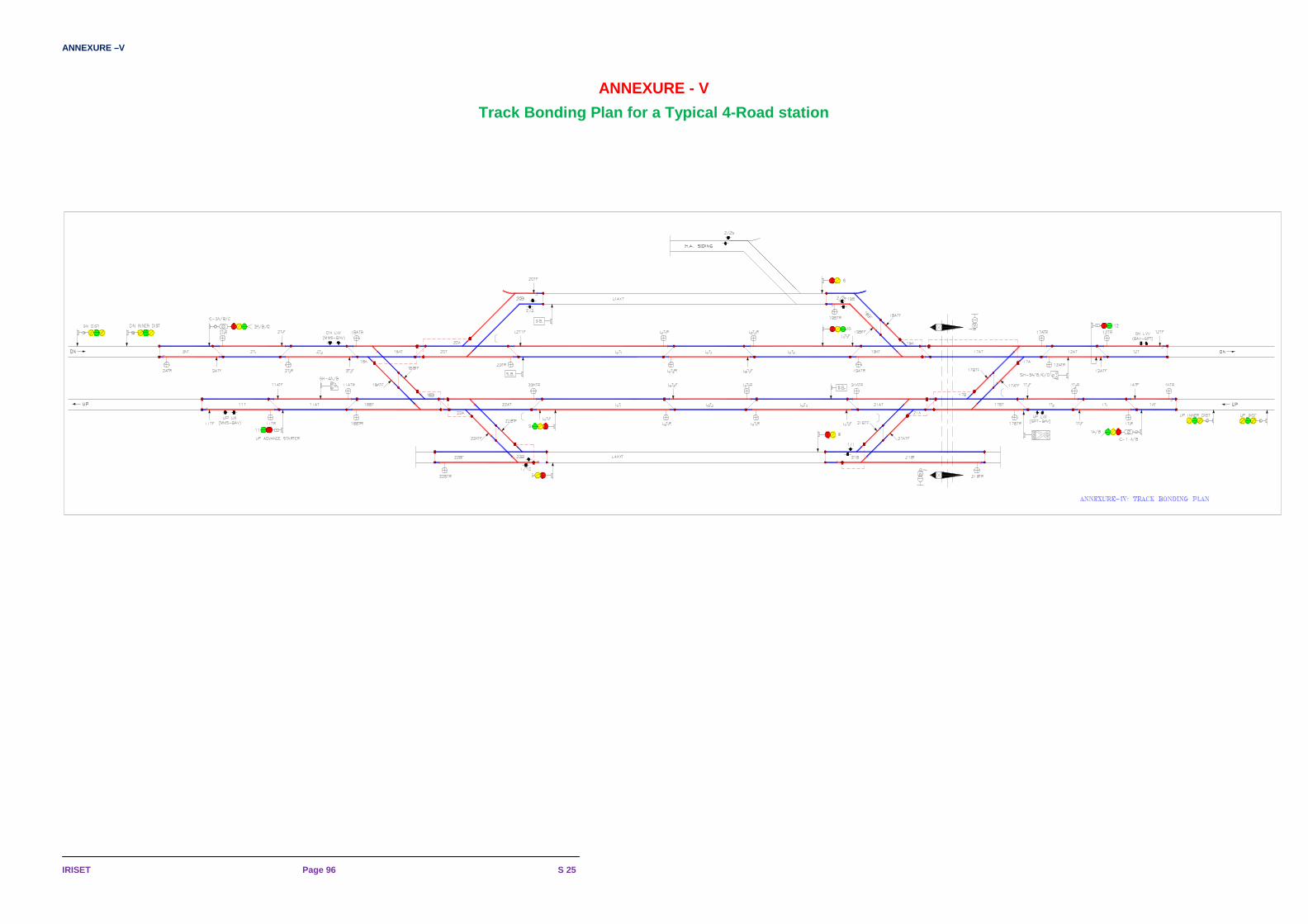
ANNEXURE –V
IRISET Page 96 S 25
ANNEXURE - V
Track Bonding Plan for a Typical 4-Road station

REVIEW QUESTIONS
S 25 Page 97 TRAIN DETECTION TRACK CIRCUITS
REVIEW QUESTIONS
CHAPTER -1, 2 &3 (DC Track Circuits) SUBJECTIVE 1. What are the factors that influence the working of Track circuits?
2. Explain the DC Single Rail track circuit with the help of wiring diagram?
3. Write the procedure for fail safe adjustment of a DC track circuit. STATE TRUE OR FALSE 1. Train shunt Resistance (TSR) is directly proportional to the Relay voltage. ( T )
2. Ballast resistance (RB) is directly proportional to the length of the Track circuit. ( F )
3. Dead section on the point zone shall not be more than 1.8 m (6’) for B.G. ( T )
4. The value of the regulating resistance used in the D.C track circuit in AC RE area is 0-30Ω (adjustable) ( T )
5. Minimum permissible Ballast resistance of a D.C track circuit in Block section shall be 2 Ω/ K.M ( F )
6. Minimum permissible Ballast resistance of a D.C track circuit in Station section shall be 2 Ω/ K.M ( T )
7. Minimum permissible value of TSR for a D.C track circuit shall be 0.5 ohms. ( T )
8. Maximum length of DC Track Circuit in AC RE area using QBAT is 750 m with B type choke at both ends. ( T )
9. The maximum limit of voltage drop across DC track relay of QTA2 is up to 300% of its pick up value. ( T )
10. The total stray current as measured, shall not exceed 10 milliamps if the length of the track circuit is less than 100metres. ( T )
11. The total stray current as measured, shall not exceed 100 milliamps if the length of the track circuit is more than or equal to 100metres. ( T )
12. Stray voltage shall not be more than 100mv irrespective of length of track circuit. ( T )
13. The insert to insert resistance of a sleeper should not be less than 500 ohms. ( T )
14. B type choke has impedance Z=120Ω and resistance = 3Ω. ( T )
15. Insulation Resistance Testing of Glued Joints is done with 100V DC Megger. ( T )
16. Insulation Resistance of a glued joint in Dry condition shall not be less than 25 MΩ when a meggering voltage of 100V DC is applied across the joint. ( T )
17. Insulation Resistance of a glued joint in wet condition shall not be less than 3 KΩ. ( T )
18. The measured TSR value of a track circuit should be always higher than the minimum TSR of 0.5 ohms. ( T )
19. Track Relay used for track circuit length up to 100 m is 2.25 Ω ( F )

REVIEW QUESTIONS, CHAPTER-1, 2&3 (DC TRACK CIRCUITS )
IRISET Page 98 S 25
20. Track Relay used for Track Circuit length more than 100 m is 2.25 Ω ( T )
21. The minimum length of a DC track circuit is 2 rail lengths (26m) ( T ) 22. The DC Track Circuit Regulating Resistance can be made zero ( F ) 23. Ballast Resistance is inversely proportional to Length of Track Circuit. ( T ) 24. When TPR drops, it indicates that the Closed Track Circuit is not occupied by the train.
( F ) 25. Transverse Bonds are provided between Positive Rails in DC Single Rail Track Circuit.
( F ) 26. Transverse Bonds are provided between Negative Rails of adjacent DC single rail track
circuits. ( T )
27. Rail Resistance is directly proportional to the length of The Track Circuit. ( T )
28. Rail Resistance shall not exceed 0.5Ω/Km., if Track Circuit Length is more than 700 m. ( T )
29. Rail Resistance shall not exceed 1.5Ω/Km, if Track Circuit Length is less than 700 m. ( T )
30. Under minimum Ballast Resistance condition, for the QBAT Track Relay, voltage across the
track relay shall not be less than 125% of its Rated Pick UP Value. ( F ) 31. Under minimum Ballast Resistance condition, voltage across the track relay shall not be less
than 125% of its Rated Pick UP Value except for QBAT. ( T ) 32. The insert-to-insert resistance of a PSC sleeper should be more than 500Ω for use in D.C
track circuit. ( T ) 33. When drop shunt test is done with 0.5ohm resistance the relay voltage should not be more
than 85% of drop away voltage. ( T ) 34. As per SEM the availability of GFN liners should be ensured up to 97% for proper working of
DC track circuit. ( T )

REVIEW QUESTIONS
S 25 Page 99 TRAIN DETECTION TRACK CIRCUITS
REVIEW QUESTIONS
CHAPTER – 5, 6 & 7 (AUDIO FREQUENCY TRACK CIRCUITS) SUBJECTIVE 1. Write the advantages of Audio Frequency Track Circuits.
2. What are the points should be taken care for AFTC installation?
3. Explain SIEMENS AFTC with the help of the functional diagram.
4. Draw the frequency and data allocation plan for different track circuits.
5. Explain ALSTOM AFTC with the help of the functional diagram. STATE TRUE OR FALSE 1. Audio frequency track circuits are generally separated by electrical joints which consist of a
rail bond and a tuning unit. ( T ) 2. Tx and Rx of same track circuits should run in one cable. ( F ) 3. In AFTC, Track Relay (QT2 or QTA2 or QBAT) is required for Train detection. ( F ) 4. In AFTC, Transmitter and Receiver of same frequency and code should not be in the same
quad cable. ( T ) 5. In AFTC, electrical isolation between two adjacent track circuits shall be achieved through
Tuning Unit. ( T ) 6. AFTC can be used in RE as well as Non-RE areas. ( T ) 7. In SIEMENS AFTC, F1 and F2 frequencies can be allotted to adjacent track circuits without
insulated rail joint. ( F ) 8. If SIEMENS AFTC is followed by SIEMENS AFTC then ‘S’ – bonds shall be used between
the two adjacent track circuits. ( T ) 9. In SIEMENS AFTC, F12 frequency can be used for track circuits provided on points and
crossing. ( F ) 10. With the introduction of AFTC in place of DC track circuit, the usage of insulated rail joints
are minimised. ( T ) 11. Where ballast and drainage conditions are poor, track circuit of more than 450m length
should be of the centre fed version. ( T ) 12. Coded track circuit enhances level of safety in all applications. ( T ) 13. In SIEMENS AFTC filter card and Receiver-1 card are frequency dependent cards. ( T ) 14. In SIEMENS AFTC data selection settings should be done in Transmitter card and also in
Demodulator card. ( T ) 15. ‘Alpha’ bonds are used where SIEMENS AFTC is followed by DC Track circuit. ( T )

REVIEW QUESTIONS, CHAPTERS - 5, 6 & 7
IRISET Page 100
16. In SIEMENS AFTC, 15 different types of data are available. ( T ) 17. 12 types of carrier frequencies are used in SIEMENS AFTC. ( T ) 18. ALSTOM AFTC works on FSK principle. ( F ) 19. ALSTOM AFTC and SIEMENS AFTC are coded track circuits. ( T ) 20. If ALSTOM AFTC is followed by SIEMENS AFTC then ‘S’ – bonds shall be used between
the two adjacent track circuits. ( F ) 21. ‘Shunt’ bond is required to be provided where ALSTOM AFTC is followed by non-track
circuited portion. ( T ) 22. 14 types (F1 to F14) of carrier frequencies are used in ALSTOM AFTC. ( T )
23. In ALSTOM AFTC, C1 to C42 codes are available as a data signal, but only three codes are
allocated for each frequency. ( T )
* * *