s3000 safety laser scanner - operating man
DESCRIPTION
S3000 Safety Laser Scanner - Operating ManualTRANSCRIPT

O P E R A T I N G I N S T R U C T I O N S
S3000
Safety Laser Scanner
GB

Operating Instructions
S3000
2 © SICK AG • Industrial Safety Systems • Germany • All rights reserved 8009942/TL59/2010-01-29
This document is protected by the law of copyright, whereby all rights established therein remain with the com-pany SICK AG. Reproduction of this document or parts of this document is only permissible within the limits of thelegal determination of Copyright Law. Alteration or abridgement of the document is not permitted without theexplicit written approval of the company SICK AG.

Operating Instructions
S3000
8009942/TL59/2010-01-29 © SICK AG • Industrial Safety Systems • Germany • All rights reserved 3
List of contents
List of contents1 About this document.........................................................................................................7
1.1 Function of this document....................................................................................71.2 Target group ..........................................................................................................71.3 Scope .....................................................................................................................71.4 Depth of information.............................................................................................81.5 Abbreviations.........................................................................................................81.6 Symbols used ........................................................................................................9
2 On safety...........................................................................................................................102.1 Specialist personnel............................................................................................102.2 Device applications.............................................................................................102.3 Correct use ..........................................................................................................112.4 General safety notes and protective measures ................................................112.5 Environmental protection ...................................................................................122.6 Applicable directives and standards..................................................................13
3 Product description.........................................................................................................143.1 Special features ..................................................................................................143.2 Function...............................................................................................................14
3.2.1 Principles of operation......................................................................153.2.2 Field set comprising of protective field and warning field ..............163.2.3 Monitoring cases...............................................................................173.2.4 Device components ..........................................................................17
3.3 Applications .........................................................................................................183.3.1 Stationary applications .....................................................................183.3.2 Mobile applications...........................................................................223.3.3 Other applications (not for personnel protection) ...........................22
3.4 S3000 variants ...................................................................................................243.4.1 Possible applications for the S3000 variants .................................26
3.5 Configurable functions........................................................................................273.5.1 Field sets ...........................................................................................273.5.2 Resolution, basic response time and scanning range....................293.5.3 Using the contour as a reference.....................................................313.5.4 Internal or external OSSDs ...............................................................333.5.5 External device monitoring (EDM)....................................................333.5.6 Application diagnostic output...........................................................343.5.7 Restart ...............................................................................................343.5.8 Multiple sampling..............................................................................363.5.9 Monitoring cases...............................................................................373.5.10 Static and dynamic control inputs for incremental encoders.........383.5.11 Checking of the monitoring case switching .....................................413.5.12 Simultaneous monitoring .................................................................413.5.13 Naming applications and laser scanners ........................................42
3.6 S3000 in master/slave operation......................................................................423.6.1 Addressing the slave.........................................................................423.6.2 Control inputs ....................................................................................423.6.3 Internal or external OSSDs ...............................................................433.6.4 Monitoring case switching ................................................................43
3.7 S3000 in combination with a Flexi Soft safety controller.................................433.7.1 Addressing the slave.........................................................................443.7.2 EFI network topologies......................................................................44
Operating Instructions
S3000
4 © SICK AG • Industrial Safety Systems • Germany • All rights reserved 8009942/TL59/2010-01-29
List of contents
3.8 Indicators and outputs .......................................................................................453.8.1 LEDs and 7segment display............................................................453.8.2 Outputs..............................................................................................46
4 Installation and mounting..............................................................................................474.1 Stationary application in horizontal operation..................................................48
4.1.1 Protective field size...........................................................................494.1.2 Measures to protect areas not covered by the S3000 ..................54
4.2 Stationary vertical operation for access protection..........................................554.2.1 Safety distance .................................................................................56
4.3 Stationary vertical operation for hazardous point protection ..........................574.3.1 Safety distance .................................................................................57
4.4 Mobile applications ............................................................................................594.4.1 Protective field length.......................................................................604.4.2 Protective field width ........................................................................634.4.3 Height of the scan plane ..................................................................634.4.4 Methods of preventing unprotected areas......................................64
4.5 Timing for monitoring case switching................................................................654.6 Mounting steps ...................................................................................................68
4.6.1 Direct mounting ................................................................................694.6.2 Mounting with mounting kit 1 ..........................................................694.6.3 Mounting with mounting kit 2 ..........................................................704.6.4 Mounting with mounting kit 3 ..........................................................714.6.5 Mounting with the Heavy Duty mounting bracket...........................724.6.6 Adhesive label Important information .............................................724.6.7 Using multiple safety laser scanners S3000 ..................................72
5 Electrical installation .....................................................................................................745.1 System connection .............................................................................................75
5.1.1 Pin assignments of the I/O modules ...............................................755.2 System plug assembly........................................................................................785.3 Pre-assembled system plugs .............................................................................80
5.3.1 Pre-assembled system plugs with flying leads................................80
6 Application and connection diagrams..........................................................................826.1 Stationary applications.......................................................................................82
6.1.1 Applications with one monitored area (S3000 Standard) .............826.1.2 Applications with multiple monitored areas (S3000
Advanced) .........................................................................................836.2 Mobile applications ............................................................................................84
6.2.1 Vehicle monitoring for unidirectional travel(S3000 Standard).............................................................................84
6.2.2 Velocity-dependent vehicle monitoring for unidirectionaltravel (S3000 Professional) .............................................................85
6.2.3 Vehicle monitoring with determination of the surroundingcontour and reflector detection (S3000 Professional CMS)..........85
6.2.4 Velocity-dependent vehicle monitoring for bi-directionaltravel (S3000 Professional with S3000 Remote) ..........................86
6.2.5 Vehicle monitoring with four safety laser scanners and theFlexi Soft modular safety controller.................................................87
6.3 Applications with sens:Control...........................................................................876.3.1 Complex system enhancements series UE100 ..............................886.3.2 Bus interfaces UE1000 series .........................................................88
6.4 Connection diagrams .........................................................................................88

Operating Instructions
S3000
8009942/TL59/2010-01-29 © SICK AG • Industrial Safety Systems • Germany • All rights reserved 5
List of contents
6.4.1 Restart interlock and external device monitoring ...........................896.4.2 Restart interlock and external device monitoring with UE10
series .................................................................................................906.4.3 Protective field switching with two static inputs..............................906.4.4 Protective field switching with four static inputs.............................916.4.5 Protective field switching with static and dynamic inputs ..............916.4.6 Protective field switching between two S3000 with static
inputs .................................................................................................926.4.7 Protective field switching between two S3000 with static
and dynamic inputs...........................................................................936.4.8 Protective field switching between an S3000 and an S300
with static and dynamic inputs.........................................................946.4.9 Protective field switching with a Flexi Soft safety controller...........95
7 Configuration ...................................................................................................................967.1 Default delivery status ........................................................................................967.2 Preparation of the configuration ........................................................................96
8 Commissioning ................................................................................................................978.1 Initial commissioning ..........................................................................................97
8.1.1 Power up sequence...........................................................................978.2 Test notes ............................................................................................................98
8.2.1 Pre-commissioning tests...................................................................988.2.2 Regular inspection of the protective device by qualified
personnel...........................................................................................988.2.3 Daily testing of the protective device by a specialist or
authorised personnel........................................................................998.3 Re-commissioning............................................................................................ 100
9 Care and maintenance................................................................................................. 1029.1 Cleaning the front screen ................................................................................ 1029.2 Replacing the front screen .............................................................................. 1029.3 Replacing the I/O module................................................................................ 105
10 Diagnostics ................................................................................................................... 10710.1 In the event of faults or errors......................................................................... 10710.2 SICK Support .................................................................................................... 10710.3 Indications and error messages...................................................................... 10710.4 Errors displayed by the 7segment display..................................................... 10810.5 Extended diagnostics....................................................................................... 113
11 Technical specifications.............................................................................................. 11411.1 Characteristics ................................................................................................. 114
11.1.1 Scanning range .............................................................................. 11411.1.2 Reset pulse..................................................................................... 115
11.2 OSSD response times ...................................................................................... 11511.3 Timing behaviour of the OSSDs....................................................................... 11711.4 Data sheet ........................................................................................................ 11911.5 EFI status information and control commands .............................................. 12711.6 Dimensional drawings ..................................................................................... 129
11.6.1 S3000............................................................................................. 12911.6.2 Mounting kits.................................................................................. 13011.6.3 Scan plane origin ........................................................................... 131
12 Ordering information.................................................................................................... 13212.1 Items supplied.................................................................................................. 132

Operating Instructions
S3000
6 © SICK AG • Industrial Safety Systems • Germany • All rights reserved 8009942/TL59/2010-01-29
List of contents
12.2 Available systems .............................................................................................13212.3 Accessories/spare parts ..................................................................................133
12.3.1 Sensor heads ..................................................................................13312.3.2 I/O modules ....................................................................................13312.3.3 Mounting kits ..................................................................................13312.3.4 System plug.....................................................................................13412.3.5 Service cable...................................................................................13412.3.6 Self assembly connecting cables ..................................................13512.3.7 Documentation ...............................................................................13512.3.8 Safety relays/compact safety controller .......................................13512.3.9 Safety controllers............................................................................13612.3.10 Network solutions...........................................................................13612.3.11 SDL connecting cables...................................................................13612.3.12 Miscellaneous.................................................................................137
13 Annex..............................................................................................................................13813.1 EC Declaration of conformity ...........................................................................13813.2 Manufacturer’s checklist .................................................................................13913.3 Glossary.............................................................................................................14013.4 List of tables .....................................................................................................14113.5 List of illustrations ............................................................................................142

Operating Instructions Chapter 1
S3000
8009942/TL59/2010-01-29 © SICK AG • Industrial Safety Systems • Germany • All rights reserved 7
About this document
1 About this documentPlease read this chapter carefully before working with this documentation and the S3000.
1.1 Function of this documentThese operating instructions are designed to address the technical personnel of themachine manufacturer or the machine operator in regards to correct mounting, electricalinstallation, commissioning, operation and maintenance of the S3000 safety laserscanner.
These operating instructions do not provide instructions for operating the machine, thesystem or the vehicle on which the safety laser scanner is, or will be, integrated. Informa-tion on this is to be found in the appropriate operating instructions of the machine, thesystem or the vehicle.
1.2 Target groupThese operating instructions are addressed to planning engineers, developers and theoperators of machines and systems which are to be protected by one or several S3000safety laser scanners. They also address people who integrate the S3000 into a machine,a system or a vehicle, initialise its use, or who are in charge of servicing and maintainingthe device.
1.3 ScopeThis document is an original document.
These operating instructions are only applicable to the S3000 safety laser scanner withone of the following entries on the type label in the field Operating Instructions:
• 8009791
• 8009791 AE N517
• 8009791 AE N702
• 8009791 AE OA34
• 8009791 AE PA46
• 8009791 AE TL59
This document is part of SICK part number 8009791 (operating instructions “S3000Safety Laser Scanner” in all available languages).
For the configuration and diagnostics of these devices you require CDS (SICKConfiguration & Diagnostic Software) version 3.6.1 or higher. To check the version of thesoftware, on the ? menu select Module info...
Note

Chapter 1 Operating Instructions
S3000
8 © SICK AG • Industrial Safety Systems • Germany • All rights reserved 8009942/TL59/2010-01-29
About this document
1.4 Depth of informationThese operating instructions contain information on the S3000 safety laser scanner:
• installation and mounting
• electrical installation
• commissioning and configuration
• care and maintenance
• fault, error diagnosis andtroubleshooting
• part numbers
• accessories
• conformity and approval
Planning and using protective devices such as the S3000 also requires specific technicalskills that are not detailed in this documentation.
General information on accident prevention using opto-electronic protective devices canbe found in the brochure “Safe Machines with opto-electronic protective devices”.
When operating the S3000, the national, local and statutory rules and regulations must beobserved.
We also refer you to the SICK AG homepage on the Internet at www.sick.de/S3000.
Here you will find information on:
• application examples
• a list of frequently asked questions regarding the S3000
• these operating instructions in different languages for viewing and printing
1.5 AbbreviationsAutomated guided vehicle
American National Standards Institute
American Wire Gauge = standardisation and classification of wires and cables by type,diameter etc.
SICK Configuration & Diagnostic Software
External device monitoring
Enhanced function interface = safe SICK device communication
Electrostatic discharge
Electro-sensitive protective equipment
Fail-safe programmable logic controller
Output signal switching device = signal output of the protective device that is used to stopthe dangerous movement
Robotic Industries Association
Note
AGV
ANSI
AWG
CDS
EDM
EFI
ESD
ESPE
FPLC
OSSD
RIA

Operating Instructions Chapter 1
S3000
8009942/TL59/2010-01-29 © SICK AG • Industrial Safety Systems • Germany • All rights reserved 9
About this document
1.6 Symbols usedRecommendations are designed to give you some assistance in your decision-makingprocess with respect to a certain function or a technical measure.
Refer to notes for special features of the device.
Display indicators show the status of the 7segment display on the S3000:� Constant indication of characters, e.g. 8� Flashing indication of characters, e.g. 8��� Alternating indication of characters, e.g. L and 2
LED symbols describe the status of an LED:� The LED is constantly illuminated.
� The LED is flashing.
� The LED is off.
These symbols identify which LED is described.
�� The “Error/Contamination” LED is flashing.
�� The “OSSDs deactivated” LED is constantly illuminated.
Instructions for taking action are shown by an arrow. Read carefully and follow the instruc-tions for action.
Warning!
A warning indicates an actual or potential risk or health hazard. Observation and imple-mentation of the warning will protect you from accidents.
Read carefully and follow the warnings!
Software notes show the location in the CDS (SICK Configuration & Diagnostic Software)where you can make the appropriate settings and adjustments. In the CDS on the Viewmenu, Dialog box, select the item File cards to go straight to the stated dialog fields. Alter-natively, the software wizard will guide you through the appropriate setting.
The term “dangerous state”
The dangerous state (standard term) of the machine is always shown in the drawings anddiagrams of this document as a movement of a machine part. In practical operation, theremay be a number of different dangerous states:
• machine movements
• vehicle movements
• electrical conductors
• visible or invisible radiation
• a combination of several risks and hazards
Recommendation
Note
�,���
�,�,�
�����
Take action …
WARNING
�

Chapter 2 Operating Instructions
S3000
10 © SICK AG • Industrial Safety Systems • Germany • All rights reserved 8009942/TL59/2010-01-29
On safety
2 On safetyThis chapter deals with your own safety and the safety of the equipment operators.
Please read this chapter carefully before working with the S3000 or with the machineprotected by the S3000.
2.1 Specialist personnelThe S3000 safety laser scanner must be installed, connected, commissioned and servicedonly by specialist personnel. Specialist personnel are defined as persons who
• due to their specialist training and experience have adequate knowledge of the power-driven equipment to be checked
and
• who have been instructed by the responsible machine operator in the operation of themachine and the current valid safety guidelines
and
• are sufficiently familiar with the applicable official health and safety regulations, direc-tives and generally recognised engineering practice (e.g. DIN standards, VDE stipula-tions, engineering regulations from other EC member states) that they can assess thework safety aspects of the power-driven equipment
and
• who have access to these operating instructions and who have read them.
As a rule these are specialist personnel from the ESPE manufacturer or also those personswho have been appropriately trained at the ESPE manufacturer, are primarily involved inchecking ESPE and are allocated the task by the organisation operating the ESPE.
2.2 Device applicationsThe S3000 safety laser scanner is used to protect persons and plant. It is intended to beused to monitor hazardous areas indoors.
The S3000 is not intended for outdoor use.
The S3000 cannot provide protection from flying parts or from emitted radiation.
The S3000 is only intended for use in industrial environments. When used in residentialareas it can cause radio interferences.
The device is a Type 3 ESPE as defined by EN 61�4961 and CLC/TS 61�4962 and istherefore allowed for use with controls in category 3 PL d1) according to EN ISO 13�8491and SIL2 according to IEC 61�508.
The S3000 is suitable for:
• hazardous area protection
• hazardous point protection
• access protection
• vehicle protection
Depending on the application, other protective devices and measures may be required inaddition to the safety laser scanner.
1) PL e can be achieved using additional devices, e.g. by using special actuators and a safety controllerFlexi Soft. However, an exact analysis of the performance levels by a safety specialist with the aid of theSISTEMA software is always necessary.
Note
Operating Instructions Chapter 2
S3000
8009942/TL59/2010-01-29 © SICK AG • Industrial Safety Systems • Germany • All rights reserved 11
On safety
2.3 Correct useThe S3000 safety laser scanner must only be used as defined in chapter 2.2 “Deviceapplications” on page 10. It must only be used by qualified personnel on the machinewhere it has been installed and initialised by specialist personnel in accordance with theseoperating instructions. It is only permitted to be used on machines on which the dangerousstate can be stopped immediately by the S3000 and/or it is possible to prevent themachine being placed in operation.
If the device is used for any other purposes or modified in any way — also during mountingand installation — any warranty claim against SICK AG shall become void.
2.4 General safety notes and protective measures
Pay attention to the safety notes!
Please observe the following statements in order to ensure the correct use of the S3000safety laser scanner.
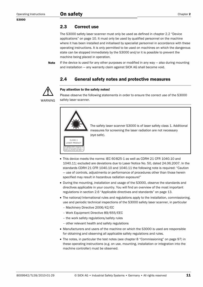
The safety laser scanner S3000 is of laser safety class 1. Additionalmeasures for screening the laser radiation are not necessary(eye safe).
• This device meets the norms: IEC 60�825-1 as well as CDRH 21 CFR 1040.10 and1040.11; excluded are deviations due to Laser Notice No. 50, dated 24.06.2007. In thestandards CDRH 21 CFR 1040.10 and 1040.11 the following note is required: “Caution— use of controls, adjustments or performance of procedures other than those hereinspecified may result in hazardous radiation exposure!”
• During the mounting, installation and usage of the S3000, observe the standards anddirectives applicable in your country. You will find an overview of the most importantregulations in section 2.6 “Applicable directives and standards” on page 13.
• The national/international rules and regulations apply to the installation, commissioning,use and periodic technical inspections of the S3000 safety laser scanner, in particular– Machinery Directive 2006/42/EC– Work Equipment Directive 89/655/EEC– the work safety regulations/safety rules– other relevant health and safety regulations
• Manufacturers and users of the machine on which the S3000 is used are responsiblefor obtaining and observing all applicable safety regulations and rules.
• The notes, in particular the test notes (see chapter 8 “Commissioning” on page 97) inthese operating instructions (e.g. on use, mounting, installation or integration into themachine controller) must be observed.
Note
WARNING

Chapter 2 Operating Instructions
S3000
12 © SICK AG • Industrial Safety Systems • Germany • All rights reserved 8009942/TL59/2010-01-29
On safety
Changes to the configuration of the devices can degrade the protective function. Afterevery change to the configuration you must therefore check the effectiveness of theprotective device. The person who makes the change is also responsible for the correctprotective function of the device. When making configuration changes, please alwaysuse the password hierarchy provided by SICK to ensure that only authorised personsmake changes to the configuration. The SICK service team is available to provideassistance if required.
• The tests must be carried out by specialist personnel or specially qualified and autho-rised personnel and must be recorded and documented to ensure that the tests can bereconstructed and retraced at any time.
• The operating instructions must be made available to the operator of the machine wherethe S3000 is used. The machine operator is to be instructed in the use of the device byspecialist personnel and must be instructed to read the operating instructions.
• The external voltage supply of the device must be capable of buffering brief mains volt-age failures of 20 ms as specified in EN 60�204. Suitable power supplies are availableas accessories from SICK (Siemens type series 6 EP 1).
Enclosed with these operating instructions is a checklist for checking by the manufac-turer and OEM (see chapter 13.2 “Manufacturer’s checklist” on page 139). Use thischecklist when checking the plant that is protected with the S3000.
2.5 Environmental protectionThe S3000 safety laser scanner is constructed in such a way that it adversely affects theenvironment as little as possible. It uses only a minimum of power and natural resources.
At work, always act in an environmentally responsible manner. For this reason please notethe following information on disposal.
Disposal
Always dispose of unserviceable or irreparable devices in compliance with local/nationalrules and regulations on waste disposal.
Remove the plastic parts and send the aluminium housing of the safety laser scanner forrecycling.
Dispose of all electronic assemblies as hazardous waste. The electronic assemblies areeasy to dismantle.
• We would be pleased to be of assistance on the disposal of this device. Contact yourlocal SICK representative.
Note

Operating Instructions Chapter 2
S3000
8009942/TL59/2010-01-29 © SICK AG • Industrial Safety Systems • Germany • All rights reserved 13
On safety
2.6 Applicable directives and standardsThe most important directives and standards, valid for the use of opto-electronic safetysystems in Europe, are listed below. Further regulations may be of importance to you,depending on the type of use. You can obtain further information of machine-specificstandards from national institutions (e.g. DIN, BSI, ANFOR etc.), the authorities or yourtrade association.
If you operate the machine or vehicle in a country outside the European Union, pleasecontact the manufacturer of the plant and the local authorities and obtain information onthe regulations and standards applicable there.
Application and installation of safety systems
Machinery Directive 2006/42/EC, e.g.:
• Safety of machinery — Basic concepts, general principles for design (EN ISO 12�100)
• Industrial automation systems — Safety of integrated manufacturing systems — Basicrequirements (ISO 11�161)
• Safety of machinery — Electrical equipment of machines — Part 1: General requirements(EN 60�204)
• Safety of machinery — Safety distances to prevent hazard zones being reached by theupper and lower limbs (EN ISO 13�857)
• Safety requirements for robots (EN ISO 10�2181)
• Safety of industrial trucks. Driverless trucks and their systems (EN 1525)
• Safety of machinery — The positioning of protective equipment in respect of approachspeeds of parts of the human body (prEN ISO 13�855)
• Safety of machinery — Principles for risk assessment (EN ISO 14�121-1)
• Safety of machinery — Safety-related parts of control systems — Part 1: Generalprinciples for design (EN ISO 13�849 part 1 and part 2)
• Safety of machines — Electro-sensitive protective equipment — Part 1: Generalrequirements (EN 61�496-1) as well as part 3: Particular requirements for Active Opto-electronic Protective Devices responsive to Diffuse Reflection (AOPDDR)(CLC/TS 61�4963)
Foreign standards, for example:
• Performance Criteria for Safeguarding (ANSI B11.19)
• Machine tools for manufacturing systems/cells (ANSI B11.20)
• Safety requirements for Industrial Robots and Robot Systems (ANSI/RIA R15.06)
• Safety Standard for guided industrial vehicles and automated functions of namedindustrial vehicles (ANSI B56.5)
To some extent these standards require the protective device to have the safety level“Control reliable”. The S3000 safety laser scanner meets this requirement.
Please request our brochure on this subject “Safe Machines with opto-electronic protectivedevices”.
Note
Recommendation

Chapter 3 Operating Instructions
S3000
14 © SICK AG • Industrial Safety Systems • Germany • All rights reserved 8009942/TL59/2010-01-29
Product description
3 Product descriptionThis chapter provides information on the special features and properties of the S3000safety laser scanner. It describes the structure and the operating principle of the device, inparticular the different operating modes.
Please read this chapter before mounting, installing and commissioning the device.
3.1 Special features• sensor heads with scanning ranges up to 4 m, 5.5 m or 7 m2)
• 190° scanning angle
• up to 8 protective fields and warning fields (dependent on the I/O module)
• the contour of the surrounding can be monitored (contour change e.g. the opening of adoor to the outside)
• integrated external device monitoring (EDM)
• integrated restart interlock/restart interlock delay for which parameters can be set
• status display with LEDs and 7segment display
• various I/O modules for different applications
• simple replacement of the I/O module (in this way the functionality can be easilyenhanced)
• dynamic protective field switching using incremental encoder inputs (S3000 Profes-sional)
• minimum response time 60 ms
• configuration using PC or notebook with SICK Configuration & Diagnostic Software
• configuration memory in the system plug. Down times are shortened by the easyreplacement of the S3000
• safe bus interfacing using SICK sens:Control products
• increased resilience to ambient light and dust due to highly effective dazzle and particlealgorithms
3.2 FunctionThe S3000 safety laser scanner only operates correctly as a protective device if thefollowing conditions are met:
• The control of the machine, system or vehicle must be electrical.
• It must be possible to transfer the dangerous state of the machine, the plant or thevehicle to a safe state at any time using the OSSDs on the S3000 after integration in thecontroller.
• The S3000 must be mounted and configured such that it detects objects as they enterthe hazardous area (see chapter 4 “Installation and mounting” on page 47).
2) Maximum protective field radii.

Operating Instructions Chapter 3
S3000
8009942/TL59/2010-01-29 © SICK AG • Industrial Safety Systems • Germany • All rights reserved 15
Product description
3.2.1 Principles of operation
The S3000 is an optical sensor that scans its surroundings in two dimensions usinginfrared laser beams. It is used to monitor a hazardous area on a machine or a vehicle.
The S3000 works on the principle of timeofflight measurement �. It sends out very shortpulses of light (S). At the same time an “electronic stopwatch” is started. When the light isincident on an object, it is reflected and received by the safety laser scanner (E). From thetime between sending and reception (∆t) the S3000 calculates the distance to the object.
In the S3000 there is also a mirror rotating at constant speed � that deflects the lightpulses such that they cover an arc of 190°. By determining the angle of rotation of themirror, the S3000 determines the direction of the object.
From the measured distance and the direction of the object, the safety laser scanner de-termines the exact position of the object.
The S3000 uses light pulses precisely radiated in specific directions. Thus the laserscanner does not continuously cover the area to be monitored. In this way resolutions ofbetween 30 mm and 150 mm are achieved.
Fig. 1: Principle of operation,timeofflight measurementby the S3000
Fig. 2: Principle of operationof the S3000 — light pulses
∆t
S E
S – ∆t
S
E
�
�

Chapter 3 Operating Instructions
S3000
16 © SICK AG • Industrial Safety Systems • Germany • All rights reserved 8009942/TL59/2010-01-29
Product description
Due to its active scanning principle, the S3000 does not require receivers or reflectors.This has the following advantages:
• Ease of installation.
• You can easily adapt the monitored area to the hazardous area on a machine.
• In comparison with contact sensors, there is less wear when electro-sensitive scanningis used.
3.2.2 Field set comprising of protective field and warning field
The protective field � secures the hazardous area on a machine or vehicle. As soon as thesafety laser scanner detects an object in the protective field, the S3000 switches theOSSDs to the off status and thus initiates the shutdown of the machine or stop of thevehicle.
You can define the warning field � such that the safety laser scanner detects an objectbefore the actual hazardous area and e.g. triggers a warning signal.
The protective field and warning field form a pair, the so-called field set. With the aid of theCDS you can configure these field sets and transfer them to the S3000. If the area to bemonitored changes, then you can re-configure the S3000 in software without additionalmounting effort.
Depending on the I/O module used (see section “I/O modules” on page 24) you can defineup to eight field sets and save these in the safety laser scanner. When using the safetylaser scanners S3000 Advanced, S3000 Professional and S3000 Remote this enablesyou to switch to a different field set if the monitoring situation changes (see section 3.2.3“Monitoring cases” on page 17).
Fig. 3: Protective field andwarning field
�
�
Operating Instructions Chapter 3
S3000
8009942/TL59/2010-01-29 © SICK AG • Industrial Safety Systems • Germany • All rights reserved 17
Product description
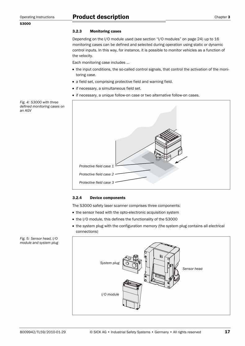
3.2.3 Monitoring cases
Depending on the I/O module used (see section “I/O modules” on page 24) up to 16monitoring cases can be defined and selected during operation using static or dynamiccontrol inputs. In this way, for instance, it is possible to monitor vehicles as a function ofthe velocity.
Each monitoring case includes …
• the input conditions, the so-called control signals, that control the activation of the moni-toring case.
• a field set, comprising protective field and warning field.
• if necessary, a simultaneous field set.
• if necessary, a unique follow-on case or two alternative follow-on cases.
3.2.4 Device components
The S3000 safety laser scanner comprises three components:
• the sensor head with the opto-electronic acquisition system
• the I/O module, this defines the functionality of the S3000
• the system plug with the configuration memory (the system plug contains all electricalconnections)
Fig. 4: S3000 with threedefined monitoring cases onan AGV
Fig. 5: Sensor head, I/Omodule and system plug
System plug
I/O module
Sensor head
Protective field case 1
Protective field case 2
Protective field case 3
Chapter 3 Operating Instructions
S3000
18 © SICK AG • Industrial Safety Systems • Germany • All rights reserved 8009942/TL59/2010-01-29
Product description
3.3 Applications
3.3.1 Stationary applications
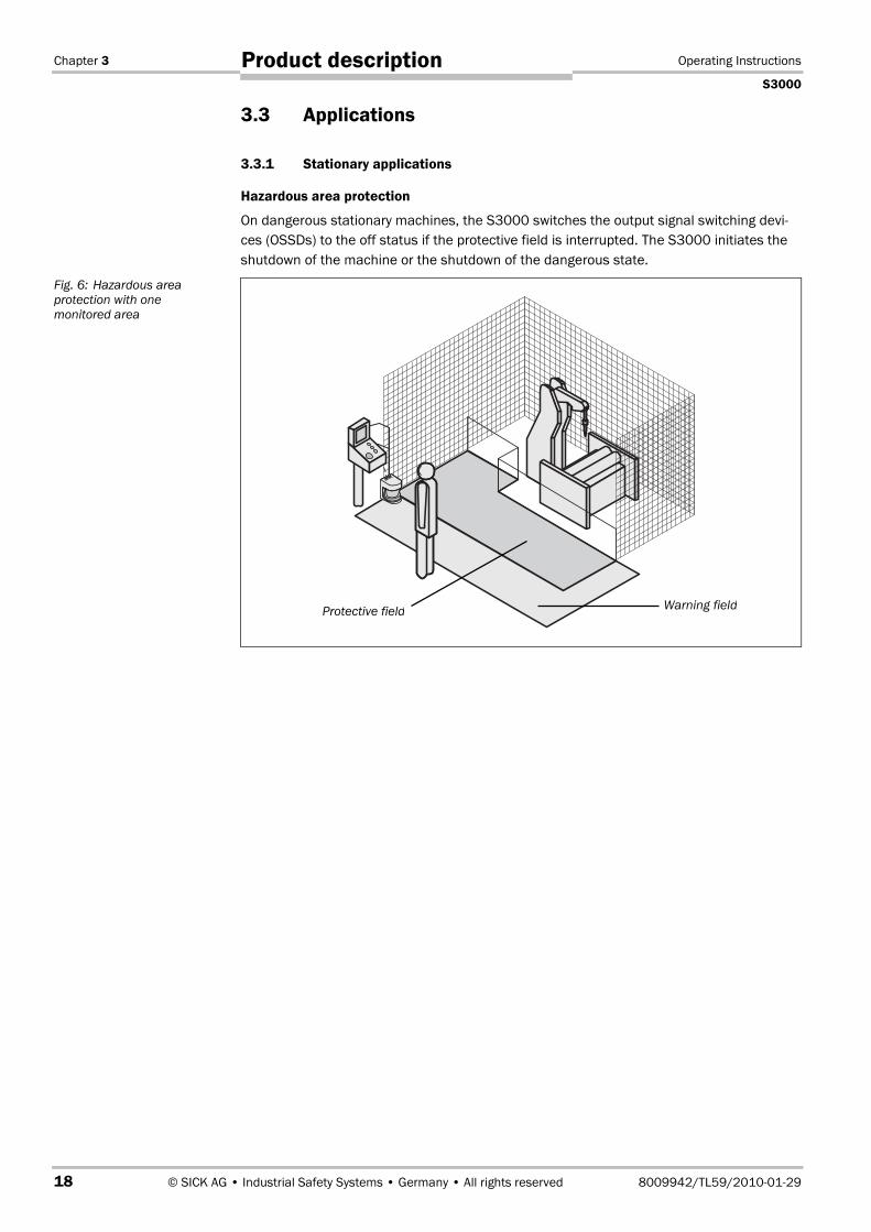
Hazardous area protection
On dangerous stationary machines, the S3000 switches the output signal switching devi-ces (OSSDs) to the off status if the protective field is interrupted. The S3000 initiates theshutdown of the machine or the shutdown of the dangerous state.
Fig. 6: Hazardous areaprotection with onemonitored area
Protective field Warning field
Operating Instructions Chapter 3
S3000
8009942/TL59/2010-01-29 © SICK AG • Industrial Safety Systems • Germany • All rights reserved 19
Product description
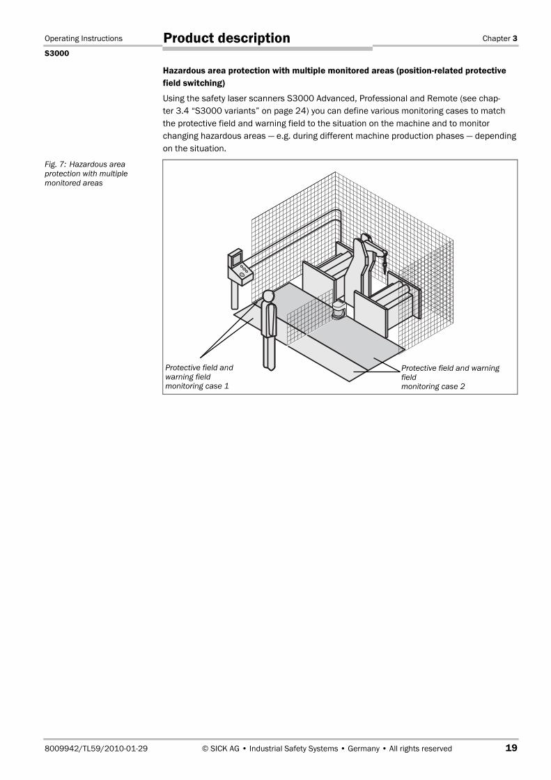
Hazardous area protection with multiple monitored areas (position-related protectivefield switching)
Using the safety laser scanners S3000 Advanced, Professional and Remote (see chap-ter 3.4 “S3000 variants” on page 24) you can define various monitoring cases to matchthe protective field and warning field to the situation on the machine and to monitorchanging hazardous areas — e.g. during different machine production phases — dependingon the situation.
Fig. 7: Hazardous areaprotection with multiplemonitored areas
Protective field andwarning fieldmonitoring case 1
Protective field and warningfieldmonitoring case 2
Chapter 3 Operating Instructions
S3000
20 © SICK AG • Industrial Safety Systems • Germany • All rights reserved 8009942/TL59/2010-01-29
Product description
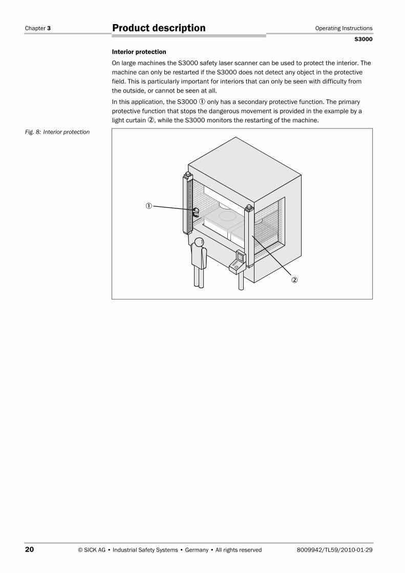
Interior protection
On large machines the S3000 safety laser scanner can be used to protect the interior. Themachine can only be restarted if the S3000 does not detect any object in the protectivefield. This is particularly important for interiors that can only be seen with difficulty fromthe outside, or cannot be seen at all.
In this application, the S3000 � only has a secondary protective function. The primaryprotective function that stops the dangerous movement is provided in the example by alight curtain �, while the S3000 monitors the restarting of the machine.
Fig. 8: Interior protection
�
�
Operating Instructions Chapter 3
S3000
8009942/TL59/2010-01-29 © SICK AG • Industrial Safety Systems • Germany • All rights reserved 21
Product description
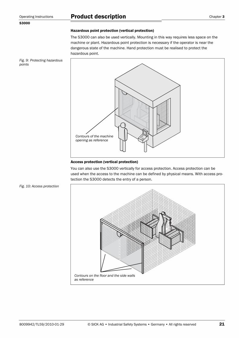
Hazardous point protection (vertical protection)
The S3000 can also be used vertically. Mounting in this way requires less space on themachine or plant. Hazardous point protection is necessary if the operator is near thedangerous state of the machine. Hand protection must be realised to protect thehazardous point.
Access protection (vertical protection)
You can also use the S3000 vertically for access protection. Access protection can beused when the access to the machine can be defined by physical means. With access pro-tection the S3000 detects the entry of a person.
Fig. 9: Protecting hazardouspoints
Fig. 10: Access protection
Contours of the machineopening as reference
Contours on the floor and the side wallsas reference

Chapter 3 Operating Instructions
S3000
22 © SICK AG • Industrial Safety Systems • Germany • All rights reserved 8009942/TL59/2010-01-29
Product description
3.3.2 Mobile applications
The S3000 can be used both on manually controlled vehicles, e.g. fork lift trucks, and alsoon automated guided vehicles (AGV) or trolleys.
Velocity-dependent protective field switching
You can use the S3000 on vehicles, e.g. to protect the route of a vehicle through a factorybuilding. If there is a person or an obstacle in the hazardous area, the S3000 ensures thatthe vehicle reduces speed and stops if necessary.
Several user defined monitoring cases are used to monitor the hazardous areas differentlyat varying velocities. You can acquire the velocity of the vehicle using incrementalencoders, and using this information dynamically adapt field sets of varying size to thevehicle velocity (see section “Incremental encoder specification” on page 77).
3.3.3 Other applications (not for personnel protection)
Along with safety-related applications, you can also use the S3000 for applications inwhich people do not need to be protected.
Collision protection
Along with people, you can also, for instance, protect vehicles from colliding with otherobjects.
As soon as vehicle � reaches the warning field of vehicle �, vehicle � slows down. Whenvehicle � reaches the protective field of vehicle �, vehicle � stops.
Fig. 11: Velocity-dependentprotective field switching
Fig. 12: Collision protection
�
�
Protective field case 1
Protective field case 2
Protective field case 3
Operating Instructions Chapter 3
S3000
8009942/TL59/2010-01-29 © SICK AG • Industrial Safety Systems • Germany • All rights reserved 23
Product description
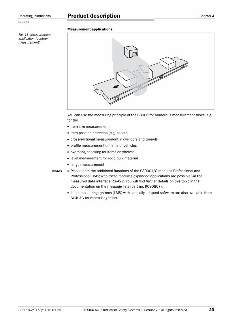
Measurement applications
You can use the measuring principle of the S3000 for numerous measurement tasks, e.g.for the
• item size measurement
• item position detection (e.g. pallets)
• cross-sectional measurement in corridors and tunnels
• profile measurement of items or vehicles
• overhang checking for items on shelves
• level measurement for solid bulk material
• length measurement
• Please note the additional functions of the S3000 I/O modules Professional andProfessional CMS; with these modules expanded applications are possible via themeasured data interface RS422. You will find further details on this topic in thedocumentation on the message lists (part no. 9090807).
• Laser measuring systems (LMS) with specially adapted software are also available fromSICK AG for measuring tasks.
Fig. 13: Measurementapplication “contourmeasurement”
Notes

Chapter 3 Operating Instructions
S3000
24 © SICK AG • Industrial Safety Systems • Germany • All rights reserved 8009942/TL59/2010-01-29
Product description
3.4 S3000 variantsTo cover the stated applications, there are 15 S3000 variants. These are formed by threesensor heads and five I/O modules.
Sensor heads
The sensor heads differ in the maximum scanning range and the resulting size of theprotective field.
The protective field ranges are the maximum achievable radial distances from the safetylaser scanner. They are achieved in applications with a resolution of 70 mm and coarser.
I/O modules
Five I/O modules are available for the S3000. With the aid of these I/O modules, theS3000 covers the various application areas.
Fig. 14: Protective fieldranges of the sensor heads
Note
Fig. 15: AvailableI/O modules
Standard
Advanced
Professional
Remote
Professional CMS
Long-rangesensor head
Medium-rangesensor head
Max. 7 mMax. 5.5 mMax. 4 m
Short-rangesensor head

Operating Instructions Chapter 3
S3000
8009942/TL59/2010-01-29 © SICK AG • Industrial Safety Systems • Germany • All rights reserved 25
Product description
Functions Stan
dard
Adva
nced
Prof
essi
onal
Prof
essi
onal
CMS
Rem
ote
Pairs of output signal switching devices (OSSDs) 1 1 1 1 1
External device monitoring (EDM) Yes Yes Yes Yes Yes
Restart interlock/delay Yes Yes Yes Yes Yes
Application diagnostic output (warning fieldinterrupted, control switch, restart or resetpressed, error/contamination)
3 3 3 3 3
Field sets for the simultaneous monitoring of twoareas
Yes Yes Yes Yes Yes
Switchable field sets 1 4 8 8 83)
Programmable monitoring cases 1 4 16 16 164)
EFI (safe SICK device communication) for thecombination of two S3000 in one system (vehiclemonitoring with bi-directional travel) or for a businterface to devices in the Flexi Soft/Classic, EFIgateways series (function enhancement)
Yes Yes Yes Yes Yes
Static control inputs for switching between themonitoring cases (complementary or 1-of-n)
– 2 2 2 –
Universal control inputs. The inputs can be usedboth as static (complementary or 1-of-n) controlinputs and as dynamic control inputs for switchingbetween the monitoring cases.
– – 2 2 –
Output of the measured data (surroundingcontour)
Yes Yes Yes Yes Yes
Filter function for the measured data – – – Yes –
Reflector detection – – – Yes –
Configurable message structure – – – Yes –
The CDROM “CDS & Manuals” contains additional documentation on the topics ofmeasured data output, filter functions, reflector detection and message structure (PDF filein German and English).
3) Maximum possible number of field sets — the actual number is the same as for the S3000 variant to which anS3000 Remote is connected.
4) Maximum possible number of monitoring cases — the actual number is the same as for the S3000 variant towhich an S3000 Remote is connected.
Tab. 1: Functionsof the I/O modules
Note

Chapter 3 Operating Instructions
S3000
26 © SICK AG • Industrial Safety Systems • Germany • All rights reserved 8009942/TL59/2010-01-29
Product description
3.4.1 Possible applications for the S3000 variants
Typical application Functionality required Necessary variant
Protection of a robot inser-tion station
One field set S3000 Standard
Protection of a pipe bendingmachine
Up to four switchable fieldsets
S3000 Advanced
Protection of a complexmaterial processing system
Up to eight switchable fieldsets
S3000 Professional
Protection of an automatedguided vehicle AGV with bi-directional travel
In each direction of travelup to eight velocity-dependent switchable fieldsets
S3000 Professionaltogether with S3000Remote
Protection of an automatedguided vehicle (AGV) withoutput of processed meas-ured data (for assistingcontrol, e.g. during dockingmanoeuvres)
Up to eight velocity-depen-dent switchable field sets,separate data interface forthe output of room contourand reflector detection
S3000 Professional CMS
Tab. 2: Possible applicationsfor the I/O modules

Operating Instructions Chapter 3
S3000
8009942/TL59/2010-01-29 © SICK AG • Industrial Safety Systems • Germany • All rights reserved 27
Product description
3.5 Configurable functions
3.5.1 Field sets
Configuring the protective field and warning field
Check the protective fields configured!
Prior to commissioning the machine or vehicle, check the configuration of the protectivefields using the instructions in chapter 8 “Commissioning” on page 97 and using thechecklist on page 139.
The area to be monitored is scanned radially by the S3000. The S3000 cannot “seearound a corner”. The area behind objects that are in the area to be monitored (pillars,grilles, etc.) can thus not be monitored.
• The protective field (�) can cover up to 190° and, depending on the sensor head, havea radius of up to 4 m, 5.5 m or up to 7 m.
• The warning field (�) can cover up to 190° and have a radius of up to 49 m. Thedetection is dependent on the remission (e.g. objects with 20�% remission can bedetected at a radius of up to 20 m).
With the aid of the CDS you can configure the field set, which comprises a protective fieldand a warning field. During this process you configure the shape and size of the protectivefield and the warning field. You can realise any field shape required.
WARNING
Note
Fig. 16: Radii ofprotective field andwarning field
�
�
�
4 m/5.5 m/7 m E.g. 20 m
at 20�%remission

Chapter 3 Operating Instructions
S3000
28 © SICK AG • Industrial Safety Systems • Germany • All rights reserved 8009942/TL59/2010-01-29
Product description
If the protective field or warning field stretches as far as a wall or another object (pillar,neighbouring machine, shelf), there must be a distance of 100 mm between the protectivefield or warning field and the object �.
Secure unprotected areas
If it is to be possible to access a narrow strip between the protective field and a wall oranother object, you must protect this strip using additional measures (e.g. fence or floorprotection).
Protective field suggested by the safety laser scanner
The CDS can suggest a protective field. The safety laser scanner scans the visible roomcontour several times. During this process possible measurement errors are taken intoaccount. From the data obtained in this way the CDS determines the contour of thesurrounding.
You can obtain the suggestion for the protective field in the field set editor in the CDS.
The size determined for the protective field is …
• as large as the visible room contour �.
• as large as the maximum scanning range of the safety laser scanner � in places wherethere is no room contour within the scanning range.
The measurement tolerances of the S3000 are automatically subtracted from theprotective field suggested. The protective field is then a distance of 100 mm from walls orobjects �.
Note
Fig. 17: Configuringprotective field and warningfield
WARNING
�
Note
�
Protective field
Warning field
Operating Instructions Chapter 3
S3000
8009942/TL59/2010-01-29 © SICK AG • Industrial Safety Systems • Germany • All rights reserved 29
Product description
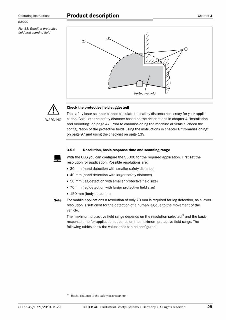
Check the protective field suggested!
The safety laser scanner cannot calculate the safety distance necessary for your appli-cation. Calculate the safety distance based on the descriptions in chapter 4 “Installationand mounting” on page 47. Prior to commissioning the machine or vehicle, check theconfiguration of the protective fields using the instructions in chapter 8 “Commissioning”on page 97 and using the checklist on page 139.
3.5.2 Resolution, basic response time and scanning range
With the CDS you can configure the S3000 for the required application. First set theresolution for application. Possible resolutions are:
• 30 mm (hand detection with smaller safety distance)
• 40 mm (hand detection with larger safety distance)
• 50 mm (leg detection with smaller protective field size)
• 70 mm (leg detection with larger protective field size)
• 150 mm (body detection)
For mobile applications a resolution of only 70 mm is required for leg detection, as a lowerresolution is sufficient for the detection of a human leg due to the movement of thevehicle.
The maximum protective field range depends on the resolution selected5) and the basicresponse time for application depends on the maximum protective field range. Thefollowing tables show the values that can be configured:
5) Radial distance to the safety laser scanner.
Fig. 18: Reading protectivefield and warning field
WARNING
�
Note
Protective field
�
�
�
Chapter 3 Operating Instructions
S3000
30 © SICK AG • Industrial Safety Systems • Germany • All rights reserved 8009942/TL59/2010-01-29
Product description
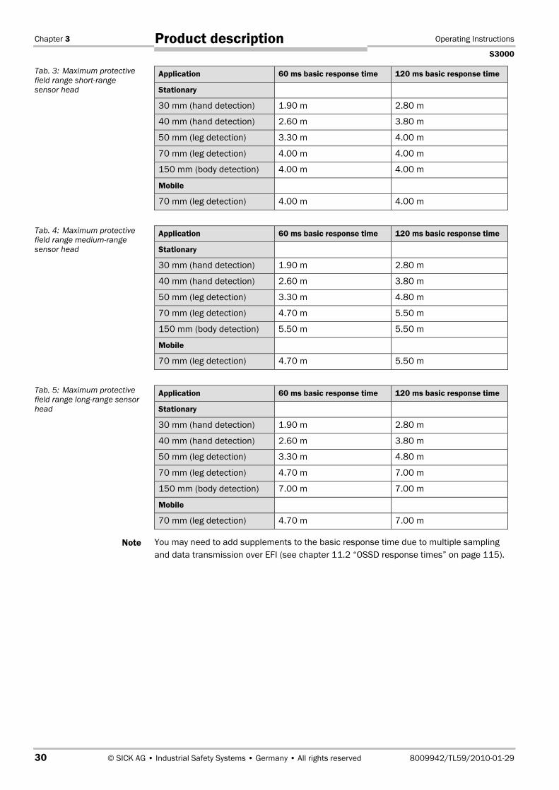
Application 60 ms basic response time 120 ms basic response time
Stationary
30 mm (hand detection) 1.90 m 2.80 m
40 mm (hand detection) 2.60 m 3.80 m
50 mm (leg detection) 3.30 m 4.00 m
70 mm (leg detection) 4.00 m 4.00 m
150 mm (body detection) 4.00 m 4.00 m
Mobile
70 mm (leg detection) 4.00 m 4.00 m
Application 60 ms basic response time 120 ms basic response time
Stationary
30 mm (hand detection) 1.90 m 2.80 m
40 mm (hand detection) 2.60 m 3.80 m
50 mm (leg detection) 3.30 m 4.80 m
70 mm (leg detection) 4.70 m 5.50 m
150 mm (body detection) 5.50 m 5.50 m
Mobile
70 mm (leg detection) 4.70 m 5.50 m
Application 60 ms basic response time 120 ms basic response time
Stationary
30 mm (hand detection) 1.90 m 2.80 m
40 mm (hand detection) 2.60 m 3.80 m
50 mm (leg detection) 3.30 m 4.80 m
70 mm (leg detection) 4.70 m 7.00 m
150 mm (body detection) 7.00 m 7.00 m
Mobile
70 mm (leg detection) 4.70 m 7.00 m
You may need to add supplements to the basic response time due to multiple samplingand data transmission over EFI (see chapter 11.2 “OSSD response times” on page 115).
Tab. 3: Maximum protectivefield range short-rangesensor head
Tab. 4: Maximum protectivefield range medium-rangesensor head
Tab. 5: Maximum protectivefield range long-range sensorhead
Note
Operating Instructions Chapter 3
S3000
8009942/TL59/2010-01-29 © SICK AG • Industrial Safety Systems • Germany • All rights reserved 31
Product description
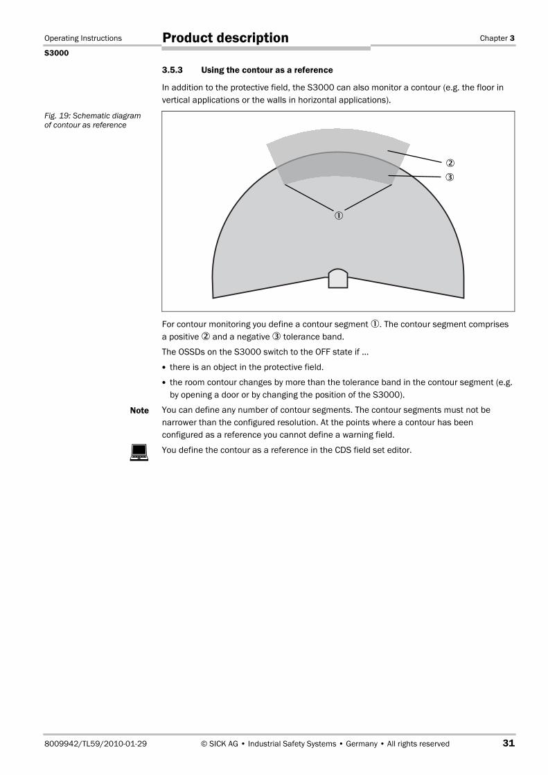
3.5.3 Using the contour as a reference
In addition to the protective field, the S3000 can also monitor a contour (e.g. the floor invertical applications or the walls in horizontal applications).
For contour monitoring you define a contour segment �. The contour segment comprisesa positive � and a negative � tolerance band.
The OSSDs on the S3000 switch to the OFF state if …
there is an object in the protective field.
the room contour changes by more than the tolerance band in the contour segment (e.g.by opening a door or by changing the position of the S3000).
You can define any number of contour segments. The contour segments must not benarrower than the configured resolution. At the points where a contour has beenconfigured as a reference you cannot define a warning field.
You define the contour as a reference in the CDS field set editor.
Fig. 19: Schematic diagramof contour as reference
Note
�
�
�
�

Chapter 3 Operating Instructions
S3000
32 © SICK AG • Industrial Safety Systems • Germany • All rights reserved 8009942/TL59/2010-01-29
Product description
Vertical operation
In vertical operation (for access protection and hazardous point protection) according toCLC/TS 61�496-3 you must always configure the protective fields used with the contour asreference function.
Use lateral, vertical boundaries of the opening (e.g. door frames) and the floor asreference. If in this case the position of the S3000 is changed in one or more planes, thedistance to the reference changes and the S3000 switches its OSSDs to the OFF state.
Horizontal operation
During horizontal operation, you can also use the contour as reference function, e.g. sothat if a door is opened (change to the room contour) the OSSDs on the S3000 are placedin the OFF state.
Fig. 20: Contour as referencefor vertical operation
Recommendation
Fig. 21: Contour as referencefor horizontal operation
Door as reference
Contours of the machine opening
Protective field
Contour segment

Operating Instructions Chapter 3
S3000
8009942/TL59/2010-01-29 © SICK AG • Industrial Safety Systems • Germany • All rights reserved 33
Product description
3.5.4 Internal or external OSSDs
On a system with two safety laser scanners S3000 or on an S3000 that is connected to aswitching amplifier or a bus node (series UE100 or UE1000), you can define which outputis switched by the protective field or the protective fields.
• Internal OSSDs
Defines that the protective field or the protective fields switch the OSSDs on S3000.
• External OSSDsThe S3000 transmits the status of the field sets (protective field/warning field) over theEFI. The OSSDs on another device connected via the EFI have switched.
– S3000 connected: The OSSDs on the second S3000 are switched.– Switching amplifier connected (UE100 series): The OSSDs on the switching device are
switched.– Bus node connected (UE1000 series): Using the bus node the information is passed to
an FPLC that must shutdown the dangerous state.
Only connect the OSSDs to a single subsequent switching element!
Each output signal switching device (OSSD) is only allowed to be connected to one switch-ing element (e.g. relay or contactor). If several switching elements are required, then youmust choose a suitable form of contact duplication.
3.5.5 External device monitoring (EDM)
The EDM function monitors the contact elements activated by both the OSSDs (e.g.contactors). The machine is only allowed to start if both contactors are in the de-energisedstate on reset, that is they are deactivated.
The S3000 monitors the contactors after every interruption of the protective field andbefore the restart of the machine. The EDM can therefore detect if one of the contacts onthe contactor has fused, for instance.�
You can configure the external device monitoring in the CDS.
• If no internal restart interlock is configured, then …– the system locks completely (lockout).– the error message � appears in the 7segment display.
• If an internal restart interlock is configured, then …
– the S3000 deactivates its OSSDs.– the adjacent LED illuminates.– the error message � appears in the 7segment display.– with the flashing LED the S3000 signals that the control switch for restarting or reset-
ting the restart must be operated.
• You will find examples on the connection of the external device monitoring in chapter 6.4“Connection diagrams” on page 88.
• If you do not use the external device monitoring function, leave the inputs disconnected(see chapter 5.1.1 “Pin assignments of the I/O modules” on page 75).
�
WARNING
�
��
��
Notes
Chapter 3 Operating Instructions
S3000
34 © SICK AG • Industrial Safety Systems • Germany • All rights reserved 8009942/TL59/2010-01-29
Product description
3.5.6 Application diagnostic output
The S3000 has an application diagnostic output that can be configured. For theapplication diagnostic output you configure in the CDS …
• whether it is deactivated.
• whether a signal is only output when the front screen is contaminated.
• whether a signal is only output on errors.
• whether a signal is output both for front screen contamination and on errors.
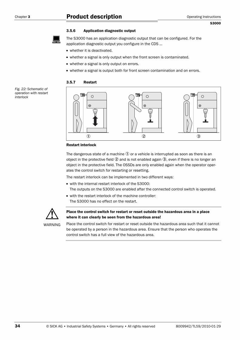
3.5.7 Restart
Restart interlock
The dangerous state of a machine � or a vehicle is interrupted as soon as there is anobject in the protective field � and is not enabled again �, even if there is no longer anobject in the protective field. The OSSDs are only enabled again when the operator oper-ates the control switch for restarting or resetting.
The restart interlock can be implemented in two different ways:
• with the internal restart interlock of the S3000:The outputs on the S3000 are enabled after the connected control switch is operated.
• with the restart interlock of the machine controller:The S3000 has no effect on the restart.
Place the control switch for restart or reset outside the hazardous area in a placewhere it can clearly be seen from the hazardous area!
Place the control switch for restart or reset outside the hazardous area such that it cannotbe operated by a person in the hazardous area. Ensure that the person who operates thecontrol switch has a full view of the hazardous area.
�
Fig. 22: Schematic ofoperation with restartinterlock
WARNING
� � �
Operating Instructions Chapter 3
S3000
8009942/TL59/2010-01-29 © SICK AG • Industrial Safety Systems • Germany • All rights reserved 35
Product description
Restart delay
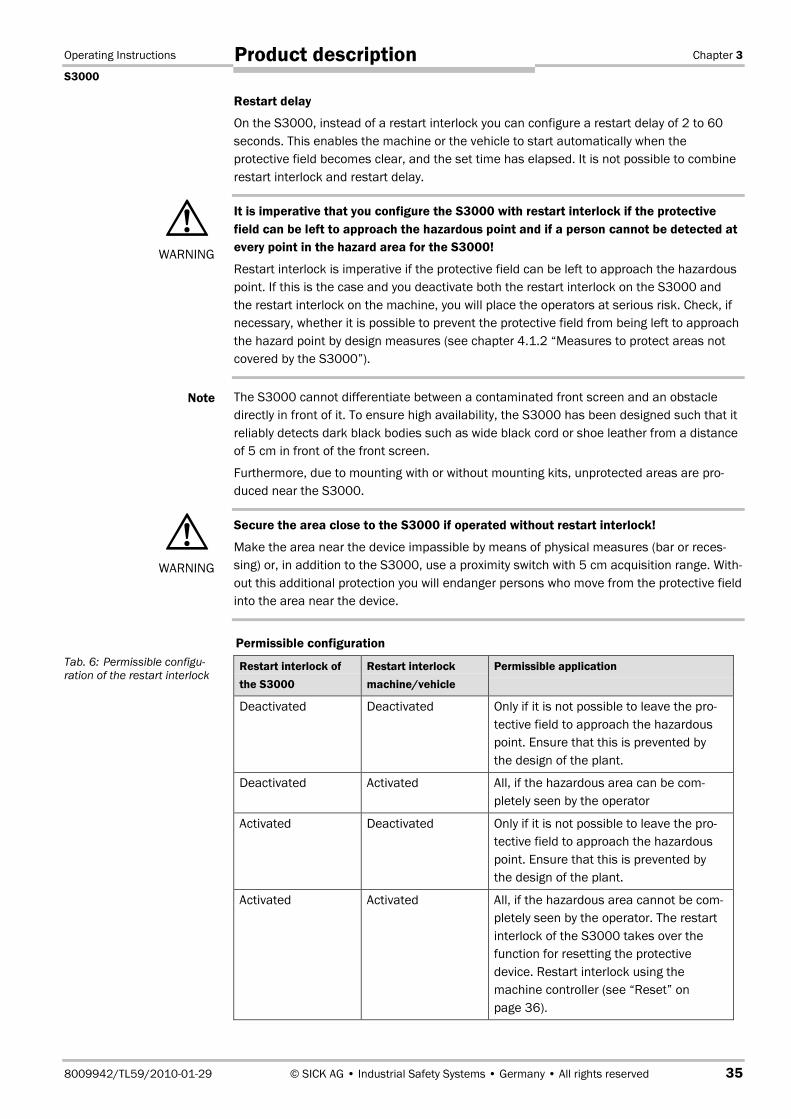
On the S3000, instead of a restart interlock you can configure a restart delay of 2 to 60seconds. This enables the machine or the vehicle to start automatically when theprotective field becomes clear, and the set time has elapsed. It is not possible to combinerestart interlock and restart delay.
It is imperative that you configure the S3000 with restart interlock if the protectivefield can be left to approach the hazardous point and if a person cannot be detected atevery point in the hazard area for the S3000!
Restart interlock is imperative if the protective field can be left to approach the hazardouspoint. If this is the case and you deactivate both the restart interlock on the S3000 andthe restart interlock on the machine, you will place the operators at serious risk. Check, ifnecessary, whether it is possible to prevent the protective field from being left to approachthe hazard point by design measures (see chapter 4.1.2 “Measures to protect areas notcovered by the S3000”).
The S3000 cannot differentiate between a contaminated front screen and an obstacledirectly in front of it. To ensure high availability, the S3000 has been designed such that itreliably detects dark black bodies such as wide black cord or shoe leather from a distanceof 5 cm in front of the front screen.
Furthermore, due to mounting with or without mounting kits, unprotected areas are pro-duced near the S3000.
Secure the area close to the S3000 if operated without restart interlock!
Make the area near the device impassible by means of physical measures (bar or reces-sing) or, in addition to the S3000, use a proximity switch with 5 cm acquisition range. With-out this additional protection you will endanger persons who move from the protective fieldinto the area near the device.
Permissible configuration
Restart interlock ofthe S3000
Restart interlockmachine/vehicle
Permissible application
Deactivated Deactivated Only if it is not possible to leave the pro-tective field to approach the hazardouspoint. Ensure that this is prevented bythe design of the plant.
Deactivated Activated All, if the hazardous area can be com-pletely seen by the operator
Activated Deactivated Only if it is not possible to leave the pro-tective field to approach the hazardouspoint. Ensure that this is prevented bythe design of the plant.
Activated Activated All, if the hazardous area cannot be com-pletely seen by the operator. The restartinterlock of the S3000 takes over thefunction for resetting the protectivedevice. Restart interlock using themachine controller (see “Reset” onpage 36).
WARNING
Note
WARNING
Tab. 6: Permissible configu-ration of the restart interlock
Chapter 3 Operating Instructions
S3000
36 © SICK AG • Industrial Safety Systems • Germany • All rights reserved 8009942/TL59/2010-01-29
Product description
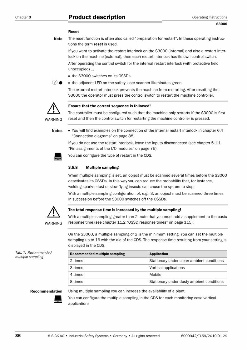
Reset
The reset function is often also called “preparation for restart”. In these operating instruc-tions the term reset is used.
If you want to activate the restart interlock on the S3000 (internal) and also a restart inter-lock on the machine (external), then each restart interlock has its own control switch.
After operating the control switch for the internal restart interlock (with protective fieldunoccupied) …
• the S3000 switches on its OSSDs.
• the adjacent LED on the safety laser scanner illuminates green.
The external restart interlock prevents the machine from restarting. After resetting theS3000 the operator must press the control switch to restart the machine controller.
Ensure that the correct sequence is followed!
The controller must be configured such that the machine only restarts if the S3000 is firstreset and then the control switch for restarting the machine controller is pressed.
• You will find examples on the connection of the internal restart interlock in chapter 6.4“Connection diagrams” on page 88.
If you do not use the restart interlock, leave the inputs disconnected (see chapter 5.1.1“Pin assignments of the I/O modules” on page 75).
You can configure the type of restart in the CDS.
3.5.8 Multiple sampling
When multiple sampling is set, an object must be scanned several times before the S3000deactivates its OSSDs. In this way you can reduce the probability that, for instance,welding sparks, dust or slow flying insects can cause the system to stop.
With a multiple sampling configuration of, e.g., 3, an object must be scanned three timesin succession before the S3000 switches off the OSSDs.
The total response time is increased by the multiple sampling!
With a multiple sampling greater than 2, note that you must add a supplement to the basicresponse time (see chapter 11.2 “OSSD response times” on page 115)!
On the S3000, a multiple sampling of 2 is the minimum setting. You can set the multiplesampling up to 16 with the aid of the CDS. The response time resulting from your setting isdisplayed in the CDS.
Recommended multiple sampling Application
2 times Stationary under clean ambient conditions
3 times Vertical applications
4 times Mobile
8 times Stationary under dusty ambient conditions
Using multiple sampling you can increase the availability of a plant.
You can configure the multiple sampling in the CDS for each monitoring case.verticalapplications
Note
� �
WARNING
Notes
�
WARNING
Tab. 7: Recommendedmultiple sampling
Recommendation
�
Operating Instructions Chapter 3
S3000
8009942/TL59/2010-01-29 © SICK AG • Industrial Safety Systems • Germany • All rights reserved 37
Product description
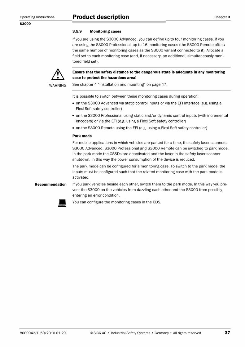
3.5.9 Monitoring cases
If you are using the S3000 Advanced, you can define up to four monitoring cases, if youare using the S3000 Professional, up to 16 monitoring cases (the S3000 Remote offersthe same number of monitoring cases as the S3000 variant connected to it). Allocate afield set to each monitoring case (and, if necessary, an additional, simultaneously moni-tored field set).
Ensure that the safety distance to the dangerous state is adequate in any monitoringcase to protect the hazardous area!
See chapter 4 “Installation and mounting” on page 47.
It is possible to switch between these monitoring cases during operation:
• on the S3000 Advanced via static control inputs or via the EFI interface (e.g. using aFlexi Soft safety controller)
• on the S3000 Professional using static and/or dynamic control inputs (with incrementalencoders) or via the EFI (e.g. using a Flexi Soft safety controller)
• on the S3000 Remote using the EFI (e.g. using a Flexi Soft safety controller)
Park mode
For mobile applications in which vehicles are parked for a time, the safety laser scannersS3000 Advanced, S3000 Professional and S3000 Remote can be switched to park mode.In the park mode the OSSDs are deactivated and the laser in the safety laser scannershutdown. In this way the power consumption of the device is reduced.
The park mode can be configured for a monitoring case. To switch to the park mode, theinputs must be configured such that the related monitoring case with the park mode isactivated.
If you park vehicles beside each other, switch them to the park mode. In this way you pre-vent the S3000 on the vehicles from dazzling each other and the S3000 from possiblyentering an error condition.
You can configure the monitoring cases in the CDS.
WARNING
Recommendation
�

Chapter 3 Operating Instructions
S3000
38 © SICK AG • Industrial Safety Systems • Germany • All rights reserved 8009942/TL59/2010-01-29
Product description
3.5.10 Static and dynamic control inputs for incremental encoders
The S3000 Advanced has two two-channel static control inputs via which the four possiblemonitoring cases can be switched.
The S3000 Professional has four two-channel control inputs via which the 16 possiblemonitoring cases can be switched. Of these four control inputs, two are static, the othertwo can be used universally as both static control inputs and also dynamic control inputs.
You can configure the control inputs in the CDS.
If you are using static sampling, decide between complementary or 1-of-n sampling depen-ding on the control features available.
When switching the monitoring cases using static and dynamic control inputs, pleasenote the following points:
Ensure that the control for the monitoring case switching has a sufficiently high level ofsafety.
Ensure that the circuit for the control inputs is suitable for the ambient conditions to beexpected so that systematic effects and thus errors on the switching of the monitoringcases can be excluded.
Ensure that the control — using static or dynamic control inputs (incremental encoderinputs) — provides switching between the monitoring cases in the correct time frame.Note that at the time of the switching there may be a person in the protective field. Onlyby means of switching in the correct time frame (i.e. before the hazard occurs at thispoint for the person) is protection provided (see chapter 4.5 “Timing for monitoring caseswitching” on page 65).
Ensure that only one safety laser scanner is connected to an incremental encoder.
Static complementary sampling
A control input comprises a pair of two connections. For correct switching one connectionmust be inverted in relation to the other.
The following table shows the levels that must be present at the connections for the con-trol input to define the logical input state 1 and 0 at the related control input.
A1 A2 Logical input state
• 1 0 0
• 0 1 1
• 1 1 Error
• 0 0 Error
Using the two control input pairs on the S3000 Advanced 22 = 4 monitoring cases can beswitched, using the four control input pairs on the S3000 Professional 24 = 16 monitoringcases can be switched.
If, on the S3000 Professional, you use two of the control input pairs as incremental enco-der inputs, the additional static switching is reduced to 4, as there are only two control in-put pairs still available.
�
WARNING
Tab. 8: Level at the connec-tions for the control inputs forcomplementary sampling
Note
Operating Instructions Chapter 3
S3000
8009942/TL59/2010-01-29 © SICK AG • Industrial Safety Systems • Germany • All rights reserved 39
Product description
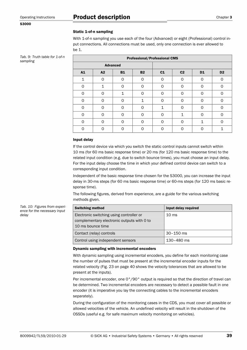
Static 1-of-n sampling
With 1-of-n sampling you use each of the four (Advanced) or eight (Professional) control in-put connections. All connections must be used, only one connection is ever allowed tobe 1.
Professional/Professional CMS
Advanced
A1 A2 B1 B2 C1 C2 D1 D2
1 0 0 0 0 0 0 0
0 1 0 0 0 0 0 0
0 0 1 0 0 0 0 0
0 0 0 1 0 0 0 0
0 0 0 0 1 0 0 0
0 0 0 0 0 1 0 0
0 0 0 0 0 0 1 0
0 0 0 0 0 0 0 1
Input delay
If the control device via which you switch the static control inputs cannot switch within10 ms (for 60 ms basic response time) or 20 ms (for 120 ms basic response time) to therelated input condition (e.g. due to switch bounce times), you must choose an input delay.For the input delay choose the time in which your defined control device can switch to acorresponding input condition.
Independent of the basic response time chosen for the S3000, you can increase the inputdelay in 30-ms steps (for 60 ms basic response time) or 60ms steps (for 120 ms basic re-sponse time).
The following figures, derived from experience, are a guide for the various switchingmethods given.
Switching method Input delay required
Electronic switching using controller orcomplementary electronic outputs with 0 to10 ms bounce time
10 ms
Contact (relay) controls 30–150 ms
Control using independent sensors 130–480 ms
Dynamic sampling with incremental encoders
With dynamic sampling using incremental encoders, you define for each monitoring casethe number of pulses that must be present at the incremental encoder inputs for therelated velocity (Fig. 23 on page 40 shows the velocity tolerances that are allowed to bepresent at the inputs).
Per incremental encoder, one 0°/90° output is required so that the direction of travel canbe determined. Two incremental encoders are necessary to detect a possible fault in oneencoder (it is imperative you lay the connecting cables to the incremental encodersseparately).
During the configuration of the monitoring cases in the CDS, you must cover all possible orallowed velocities of the vehicle. An undefined velocity will result in the shutdown of theOSSDs (useful e.g. for safe maximum velocity monitoring on vehicles).
Tab. 9: Truth table for 1-of-nsampling
Tab. 10: Figures from experi-ence for the necessary inputdelay
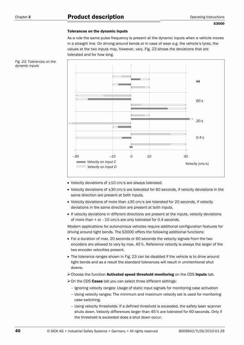
Chapter 3 Operating Instructions
S3000
40 © SICK AG • Industrial Safety Systems • Germany • All rights reserved 8009942/TL59/2010-01-29
Product description
Tolerances on the dynamic inputs
As a rule the same pulse frequency is present at the dynamic inputs when a vehicle movesin a straight line. On driving around bends or in case of wear e.g. the vehicle’s tyres, thevalues at the two inputs may, however, vary. Fig. 23 shows the deviations that aretolerated and for how long.
• Velocity deviations of ±10 cm/s are always tolerated.
• Velocity deviations of ±30 cm/s are tolerated for 60 seconds, if velocity deviations in thesame direction are present at both inputs.
• Velocity deviations of more than ±30 cm/s are tolerated for 20 seconds, if velocitydeviations in the same direction are present at both inputs.
• If velocity deviations in different directions are present at the inputs, velocity deviationsof more than + or –10 cm/s are only tolerated for 0.4 seconds.
Modern applications for autonomous vehicles require additional configuration features fordriving around tight bends. The S3000 offers the following additional functions:
• For a duration of max. 20 seconds or 60 seconds the velocity signals from the twoencoders are allowed to vary by max. 45�%. Reference velocity is always the larger of thetwo encoder velocities present.
• The tolerance ranges shown in Fig. 23 can be disabled if the vehicle is to drive aroundtight bends and as a result the standard tolerances will result in unintentional shutdowns.
Choose the function Activated speed threshold monitoring on the CDS Inputs tab.
On the CDS Cases tab you can select three different settings:
– Ignoring velocity ranges: Usage of static input signals for monitoring case activation– Using velocity ranges: The minimum and maximum velocity set is used for monitoring
case switching.– Using velocity thresholds: If a defined threshold is exceeded, the safety laser scanner
shuts down. Velocity differences larger than 45�% are tolerated for 60 seconds. Only ifthe threshold is exceeded does a shut down occur.
Fig. 23: Tolerances on thedynamic inputs
Velocity [cm/s]
0.4 s
–30 0 10 30Velocity on input C
–10
Velocity on input D
20 s
60 s
∞

Operating Instructions Chapter 3
S3000
8009942/TL59/2010-01-29 © SICK AG • Industrial Safety Systems • Germany • All rights reserved 41
Product description
The information on the minimum and maximum velocity is determined for the thresholdand in this case is not used for the velocity-dependent monitoring case activation.
• Warning — The redundant velocity monitoring by the safety laser scanner is deactivatedfor max. 60 seconds. Ensure the safety requirements for the application are met.
• For safety reasons the 60 seconds criterion must never be exceeded. The safety laserscanner then switches off its OSSDs, i.e. tight bends are not allowed to last more than60 seconds.
3.5.11 Checking of the monitoring case switching
To check the switching between monitoring cases, configure a series of monitoring cases.Here you can define either an arbitrary sequence, a unique sequence, or two alternativesequences.
• Arbitrary sequence: It is allowed to switch from one monitoring case to any other definedmonitoring case.
• Unique sequence: It is only allowed to switch from a monitoring case to another specifi-cally defined monitoring case.
• Alternative sequence: It is allowed to switch from a monitoring case to one of twospecifically defined monitoring cases.
Use the checking of the monitoring cases as an additional medium to exclude risks. Forexample, deviations of a vehicle from a corridor or a plant from the stipulated productionprocess can be detected.
Arbitrary sequence Unique sequence Alternative sequence
� � �
� � � � � �
�
3.5.12 Simultaneous monitoring
Within a monitoring case, the S3000 can monitor two field sets simultaneously (e.g.hazardous area on the left and hazardous area on the right). �For this purpose choose anyfurther field set with the related monitoring case as the simultaneous field set.
On a system with one S3000 both field sets act on the internal OSSDs in the S3000. Inaddition, the device signals protective field infringements in both field sets to an externaldevice (e.g. the UE100 series) via EFI�
On a system with two S3000, the switching signals for the two field sets can be allocatedto the OSSDs on the first or second device.
You configure a monitoring case with simultaneous field set in the CDS.
Notes
Recommendation
Fig. 24: Schematic layout ofthe monitoring caseswitching
�
Chapter 3 Operating Instructions
S3000
42 © SICK AG • Industrial Safety Systems • Germany • All rights reserved 8009942/TL59/2010-01-29
Product description
3.5.13 Naming applications and laser scanners
A name can be assigned to the application configured and to the laser scanner(s). Thenames are saved in the devices after the configuration is transferred. The name chosenmay, for example, be the identifier for the system or the machine.
If you assign unique application names, you may “reserve” the devices for certain duties.A machine maintenance person comparing exchanged devices with the configuration datasaved in the CDS will be notified that the application name does not match. He may thenexchange these devices for those with the correct application name.
You enter the application name and the name of the scanner used in the CDS.
3.6 S3000 in master/slave operationThe S3000 safety laser scanner can be incorporated in a master/slave system using anEFI connection.
• Two S3000 can form the master/slave system in which one of the safety laser scannersis the master, the other the slave.
• One S3000 together with an S300 can form the master/slave system in which theS3000 is the master and the S300 is the slave.
• An S3000 can be connected to a higher-level device (S3000, series UE100 switchingamplifier or series UE1000 bus node). In this case the S3000 is the slave.
• It is possible to connect up to four safety laser scanners to a safety controller Flexi Soft;one safety laser scanner in each pair is the master, the other the slave (see also 3.7further unten).
When the S3000 is switched on in a configured master/slave system, the followingmessage appears briefly on the 7segment display (see section 8.3 on page 100):
• � for host on the S3000 master
• � for guest on the S3000 slave
3.6.1 Addressing the slave
To unambiguously differentiate between the master device and slave device in amaster/slave system, it is possible to define a S3000 as a slave. For this purpose ajumper is wired between the connection terminals 7 (ERR) and 10 (A1) (see section 5.1.1“Pin assignments of the I/O modules” on page 75).
Connect this connection terminal only for a slave device that is connected to a master overEFI and that as a result uses the master’s control inputs and its application diagnosticoutput.
3.6.2 Control inputs
In a master/slave system, the control signals for monitoring case switching are applied tothe inputs on the master. The slave is connected to the master via EFI and receives fromthe master the input information for monitoring case switching.
You can only connect the input signals to one safety laser scanner. Distributed connectionof the input signals to two safety laser scanners is not possible.
You can configure the control inputs of the master in the CDS.
�
Note
Note
�

Operating Instructions Chapter 3
S3000
8009942/TL59/2010-01-29 © SICK AG • Industrial Safety Systems • Germany • All rights reserved 43
Product description
3.6.3 Internal or external OSSDs
In a master/slave system you define in the CDS which output signal switching device(OSSD) is switched when there is an object in the protective field.
• Internal OSSDsDefines that the protective field or the protective fields switch the OSSDs on S3000.
• External OSSDsThe S3000 transmits the status of the field sets (protective field/warning field) over theEFI. The OSSDs on another device connected via the EFI have switched.– Connected S3000 or S300: The OSSDs on the second safety laser scanner are
switched.– Connected switching amplifier (UE100 series): The OSSDs on the UE100 are switched
depending on its configuration.– Connected bus node (UE1000 series): The information is passed to an FPLC, which
further processes the information, depending on the configuration of the UE1000.
3.6.4 Monitoring case switching
In a master/slave system, the simplest device defines the number of possible monitoringcases. If, for example, a S3000 Professional and an S3000 Advanced are connectedtogether, only four monitoring cases are available to the two S3000.
A field set and the input conditions that activate the monitoring case must be allocated toeach monitoring case.
3.7 S3000 in combination with a Flexi Soft safetycontroller
The safety controller Flexi Soft provides two EFI strings; up to two safety laser scanners(S3000, S300, also mixed) can be connected to each of these strings. It is thereforepossible to realise applications with up to four safety laser scanners (see also section6.2.5 on page 87 and section 6.4.9 on page 95).
Using the safety controller Flexi Soft it is possible to monitor two protective fieldssimultaneously on one safety laser scanner. In one application it is therefore possible toconfigure up to eight protective fields and up to eight warning fields.
�
Fig. 25: S3000 and S300in combination with aFlexi Soft modular safetycontroller
Flexi Soft modularsafety controller S3000 S3000
S3000 S300

Chapter 3 Operating Instructions
S3000
44 © SICK AG • Industrial Safety Systems • Germany • All rights reserved 8009942/TL59/2010-01-29
Product description
The entire application is configured using the Flexi Soft Designer, from this user interface itis possible to start the CDS to configure the safety laser scanners.
The status of the protective and warning fields is transmitted using EFI and can becombined in the safety controller Flexi Soft as required. During this process it does notmatter whether the devices are connected using one or various EFI strings. The signal onthe safety outputs on the safety controller Flexi Soft is transferred, e.g., to a machine orvehicle control.
The monitoring cases that have been configured in the safety laser scanners can beswitched with the aid of the programmed logic blocks in the safety controller Flexi Soft.
Monitoring case switching is, however, also still possible at the local inputs if, e.g.,incremental encoders are used. The incremental encoders must always be connected tothe master. Signals from the safety controller Flexi Soft can then not be processed in thisarrangement. For this reason the simultaneous combination of local inputs on the safetylaser scanners and inputs on the safety controller is not possible.
3.7.1 Addressing the slave
To be able to unambiguously differentiate between the master device and the slave devicein a master/slave system, you must define one safety laser scanner on each EFI string asthe slave. For this purpose a jumper is wired between the connection terminals 7 (ERR)and 10 (A1) (see section 5.1.1 “Pin assignments of the I/O modules” on page 75).
The safety controller Flexi Soft can then unambiguously identify all safety laser scannersinvolved and distribute and retrieve information using bit assignment (see also TechnicalDescription “EFI — Enhanced Function Interface”, SICK part no. 8012621).
3.7.2 EFI network topologies
To connect two safety laser scanners to one of the EFI strings on a safety controllerFlexi Soft there are two possibilities:
Series connection
The two safety laser scanners are connected one after the other. The signals and thevoltage supply for the second safety laser scanner are routed via the first safety laserscanner in the EFI string.
Star configuration
The two safety laser scanners are connected to the same Flexi Soft input for the EFI string.It is possible to differentiate between the safety laser scanners using the addressing in theEFI protocol.
�

Operating Instructions Chapter 3
S3000
8009942/TL59/2010-01-29 © SICK AG • Industrial Safety Systems • Germany • All rights reserved 45
Product description
You will find details on the connection of safety laser scanners in section 6.4.9 “Protectivefield switching with a Flexi Soft safety controller” on page 95.
3.8 Indicators and outputs
3.8.1 LEDs and 7segment display
The LEDs and the 7segment display indicate the operational status of the S3000. Theyare on the front face of the safety laser scanner. Above the LEDs there are symbols thatare used in the remainder of these operating instructions to describe the LEDs.
The symbols have the following meaning:
OSSDs deactivated (e.g. if object in the protective field, reset necessary, lock-out)
Reset required
Warning field interrupted (object in warning field)
Front screen contaminated
OSSDs activated (no object in protective field)
Fig. 26: EFI networktopologies
Fig. 27: Operational statusindicators on the S3000
�����
Series connection
Star configuration
Max. 25 m
Max. 50 m
Max. 25 m
Max. 50 m

Chapter 3 Operating Instructions
S3000
46 © SICK AG • Industrial Safety Systems • Germany • All rights reserved 8009942/TL59/2010-01-29
Product description
3.8.2 Outputs
Using the outputs on the S3000 you shutdown the dangerous state on a machine, a plantor a vehicle and evaluate the operational status of the S3000. The S3000 has the follow-ing outputs:
• OSSDs
• warning field
• application diagnostic output (contamination of the front screen/error)
• reset required
The outputs are brought out at the system plug (see chapter 5.1 “System connection” onpage 75).
All outputs are only allowed to be used for the purpose specified. Note that the signals atthe application diagnostic outputs for “warning field”, “contamination of the front screen/error” and “reset necessary” are not safe. For this reason the warning field is not allowedto be used for tasks related to personnel protection.
Note

Operating Instructions Chapter 4
S3000
8009942/TL59/2010-01-29 © SICK AG • Industrial Safety Systems • Germany • All rights reserved 47
Installation and mounting
4 Installation and mountingThis chapter describes the preparation and completion of the mounting of the S3000safety laser scanner.
Mounting requires four steps:
• definition of the application and the necessary mounting location for the laser scanner
• calculation of the protective field sizesYou can enter the calculated protective field sizes with the aid of the CDS. Or leave theS3000 to suggest the protective fields. In the latter case it is necessary to checkwhether the suggested sizes correspond to those calculated. Thus in any circumstanceyou must calculate the protective field size.
• definition of the switching point between monitoring cases
• mounting the safety laser scanner with or without mounting kits
No protective function without sufficient safety distance!
The S3000’s safety function depends on the system being mounted with the correct safetydistance from the hazardous area.
Mount the S3000 in a dry place and protect the device from dirt and damage.
Avoid strong electrical fields. These can, e.g., be produced by welding cables, inductioncables in the immediate vicinity and also by mobile telephones operated in closephysical proximity.
Ensure that there are no obstacles in the area to be monitored in the field of view of theS3000 that could cause interference or shadowing. Such shadowed areas cannot bemonitored by the S3000. If there are unavoidable shadowed areas, check whether thereis a risk. Take additional safety precautions as necessary.
Keep the area to be monitored free of smoke, fog, steam or other forms of air impurities.Otherwise the function of the S3000 may be impaired and incorrect switching mayoccur.
Avoid placing highly reflective objects in the scan plane of the S3000. Examples:Retroreflectors can affect the measurement results of the S3000. Mirrored objects canhide part of the area to be monitored.
Mount the S3000 such that it is not dazzled by incident sunlight. Do not position strobo-scopic and fluorescent lights directly in the scan plane as these may affect the S3000 inspecific circumstances.
Mark the protective field on the floor, if this is reasonable for the application (seeEN 61�496, part 1, chapter 7).
The following steps are necessary after mounting and installation:
• completing the electrical connections (chapter 5 “Electrical installation”)
• configuration of the protective field (chapter 7 “Configuration”)
• commissioning and checking of the installation (chapter 8 “Commissioning”)
• checking of the S3000 functionality and safe shutdown of the machine, vehicle or plant(chapter 8.2 “Test notes”)
WARNING
Notes
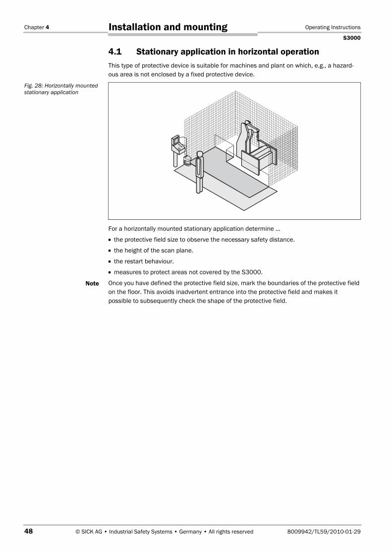
Chapter 4 Operating Instructions
S3000
48 © SICK AG • Industrial Safety Systems • Germany • All rights reserved 8009942/TL59/2010-01-29
Installation and mounting
4.1 Stationary application in horizontal operationThis type of protective device is suitable for machines and plant on which, e.g., a hazard-ous area is not enclosed by a fixed protective device.
For a horizontally mounted stationary application determine …
• the protective field size to observe the necessary safety distance.
• the height of the scan plane.
• the restart behaviour.
• measures to protect areas not covered by the S3000.
Once you have defined the protective field size, mark the boundaries of the protective fieldon the floor. This avoids inadvertent entrance into the protective field and makes itpossible to subsequently check the shape of the protective field.
Fig. 28: Horizontally mountedstationary application
Note

Operating Instructions Chapter 4
S3000
8009942/TL59/2010-01-29 © SICK AG • Industrial Safety Systems • Germany • All rights reserved 49
Installation and mounting
4.1.1 Protective field size
The protective field must be so configured that a safety distance (S) to the hazardous areais maintained. This safety distance ensures that the hazardous point can only be reachedafter the dangerous state of the machine has been completely stopped.
If you are using an S3000 Advanced, Professional or Remote, you can define severalmonitoring cases with different protective fields. In such a case you must calculate theprotective field size for all protective fields used.
You can operate the S3000 in stationary horizontal operation with 50 mm or with 70 mmresolution. For each resolution you can choose between 60 ms and 120 ms responsetime. The maximum protective field range6) for the S3000 is given by the resolution andthe response time.
• If you choose a 50 mm resolution, the maximum protective field range is less than for a70 mm resolution, however you can mount the S3000 as low as required.
• If you choose a 70 mm resolution, you can configure the largest protective field rangebut must position the scan plane of the S3000 at 300 mm.
Ensure that a human leg can be detected in horizontal stationary applications with70 mm resolution!
Mount the scan planes for horizontal stationary applications with 70 mm resolution at aheight of at least 300 mm (see “Height of the scan plane at 70 mm resolution” onpage 53).
Due to the choice of two resolutions and two response times, it may be necessary torepeatedly calculate the protective field size (iterative calculation).
Perform your protective field calculation initially based on a resolution of 50 mm and abasic response time of 60 ms.
If the calculated protective field is larger than the maximum protective field range at50 mm resolution, calculate it again using the same resolution and the higher responsetime.
If the protective field calculated is larger than the maximum protective field rangeachievable, then re-calculate the protective field with the lower resolution.
6) Radial distance to the safety laser scanner.
Note
WARNING
Recommendation

Chapter 4 Operating Instructions
S3000
50 © SICK AG • Industrial Safety Systems • Germany • All rights reserved 8009942/TL59/2010-01-29
Installation and mounting
The safety distance S depends on:
• approach speed of the body or parts of the body
• stopping/run-down time of the machine or system(The stopping/run-down time is shown in the machine documentation or must be deter-mined by taking a measurement.)
• response time of the S3000
• supplements for general measurement errors and any measurement errors related toreflection
• supplement for prevention of reaching over
• height of the scan plane
• possibly the time for switching between the monitoring cases
Calculation of the safety distance S:
First, calculate S using the following formula:S = (K × (TM + TS)) + ZG + ZR + C
Where …
K = Approach speed (1600 mm/s, defined in prEN ISO 13�855)TM = Stopping/run-down time of the machine or systemTS = Response time of the S3000 combined with the downstream controllerZG = General safety supplement = 100 mmZR = Supplement for measurement error related to reflectionC = Supplement for prevention of reaching over
Response time TS of the S3000
The response time TS of the S3000 depends on …
• the resolution used.
• the multiple sampling used.
• the transmission speed to external OSSDs over EFI.
See chapter 11.2 “OSSD response times” on page 115.
Supplement ZR for measurement error related to reflection
Avoid mounting retroreflectors at a distance of less than one meter from the boundaryof the protective field!
With retroreflectors positioned at a distance of less than 1 m from the boundary of theprotective field a supplement, ZR, of 200 mm must be added to the protective field.
WARNING

Operating Instructions Chapter 4
S3000
8009942/TL59/2010-01-29 © SICK AG • Industrial Safety Systems • Germany • All rights reserved 51
Installation and mounting
Supplement C for protection against reaching over
With a protective field installed horizontally, there is a risk that people may reach over theprotective field and in this way reach the hazardous area before the S3000 shuts downthe dangerous state. For this reason the calculation of the safety distance must take intoaccount a supplement to prevent persons from finding themselves in a hazardous situa-tion by reaching over the protective field (see EN ISO 13�857, table 1) before the S3000triggers.
The necessary supplement for the safety distance is dependent on the height of the scanplane for the protective field. At low heights � the supplement is larger than at greaterheights �.
Prevent the possibility of crawling beneath the protective device if you mount it higherthan 300 mm!
Prevent people from being able to crawl beneath the protective field by means of approp-riate mounting of the S3000. If you mount the protective device higher than 300 mm, youmust prevent crawling beneath by means of additional measures. For applications that areaccessible to the public, the mounting height may need to be reduced to 200 mm (on thissubject see the appropriate regulations).
Fig. 29: Risk of reaching over(mm)
WARNING
� �
C = 1200 C = 850
HD = 0
HD = 875

Chapter 4 Operating Instructions
S3000
52 © SICK AG • Industrial Safety Systems • Germany • All rights reserved 8009942/TL59/2010-01-29
Installation and mounting
How to calculate the supplement C:
If there is enough empty space in front of your machine or plant, use 1200 mm for thesupplement C.
If the safety distance is to be kept as small as possible, calculate C using the followingformula:C = 1200 mm – (0.4 × HD)Here HD is the height at which the protective field is mounted.
The minimum supplement to prevent reaching over is 850 mm (arm length).
In summary there are three practical methods of mounting the scan plane for the S3000.The optimal method depends on the related application.
Tab. 11 provides assistance in making the selection.
Mounting orientation Benefit Disadvantage
Scanner low (HS < 300 mm)Inclination of the scanner planelow (HD ≈ HS)
No external effects due todazzle, crawling beneathnot possible
Larger supplement C
Scanner high (HS > 300 mm)Inclination of the scanner planelow (HD ≈ HS)
Lower protective fieldsupplement C
Danger of crawlingbeneath (at the front andside)
Scanner low (HS < 300 mm)Inclination of the scanner planehigh (HD > HS)
Lower protective fieldsupplement C
Danger of crawlingbeneath (at the front),external effect due todazzle possible
HD = Detection heightHS = Scanner mounting height
Note
Fig. 30: Mounting methodsfor the scan plane
Tab. 11: Advantages anddisadvantages of mountingmethods
CCC
HDHD
HS
HS HD
HS
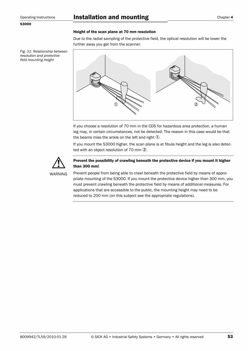
Operating Instructions Chapter 4
S3000
8009942/TL59/2010-01-29 © SICK AG • Industrial Safety Systems • Germany • All rights reserved 53
Installation and mounting
Height of the scan plane at 70 mm resolution
Due to the radial sampling of the protective field, the optical resolution will be lower thefurther away you get from the scanner.
If you choose a resolution of 70 mm in the CDS for hazardous area protection, a humanleg may, in certain circumstances, not be detected. The reason in this case would be thatthe beams miss the ankle on the left and right �.
If you mount the S3000 higher, the scan plane is at fibula height and the leg is also detec-ted with an object resolution of 70 mm �.
Prevent the possibility of crawling beneath the protective device if you mount it higherthan 300 mm!
Prevent people from being able to crawl beneath the protective field by means of appro-priate mounting of the S3000. If you mount the protective device higher than 300 mm, youmust prevent crawling beneath the protective field by means of additional measures. Forapplications that are accessible to the public, the mounting height may need to bereduced to 200 mm (on this subject see the appropriate regulations).
Fig. 31: Relationship betweenresolution and protectivefield mounting height
WARNING
� �

Chapter 4 Operating Instructions
S3000
54 © SICK AG • Industrial Safety Systems • Germany • All rights reserved 8009942/TL59/2010-01-29
Installation and mounting
4.1.2 Measures to protect areas not covered by the S3000
During mounting, areas may be found that are not covered by the safety laser scanner.
These areas � become larger if the S3000 is mounted using the mounting kits.
Size of the unprotected areas
Mounting method X Y
Direct mounting 109 mm 618 mm
With mounting kit 1 112 mm 635 mm
With mounting kit 1 and 2 127 mm 720 mm
With mounting kit 1, 2 and 3 142 mm 805 mm
Prevent unprotected areas!
Mount the S3000 such that there are no unprotected areas. Take one of the precautionsgiven in the following:
Fit cover plates to prevent standing behind.
Fit the S3000 in a recess.
Mounting with cover plates
Fit the cover plates such � that the areas not covered by the safety laser scanner arecompletely protected against personnel standing in them.
Fig. 32: Unprotected areasfor stationary applications
Tab. 12: Size of theunprotected areas
WARNING
Fig. 33: Example of mountingwith cover plates
�
�
XX
Y Y

Operating Instructions Chapter 4
S3000
8009942/TL59/2010-01-29 © SICK AG • Industrial Safety Systems • Germany • All rights reserved 55
Installation and mounting
Mounting in a recess
Design the recess � to be sufficiently deep enough that it completely covers the areanot protected by the safety laser scanner (Fig. 33) and such that standing in anunscanned area is not possible.
Prevent crawling beneath the recess by limiting the height of the recess � such thatnobody can crawl beneath.
4.2 Stationary vertical operation for access protectionAccess protection can be used when the access to the machine can be defined by physicalmeans. For access protection the S3000 detects the entry of an entire body.
• To ensure adequate access protection, a response time of ≤ 90 ms and a resolution of150 mm or finer is required.
• To protect the protective device against inadvertent adjustment or manipulation, youmust use the contour of the surrounding area as a reference for the S3000 (see chap-ter 3.5.3 “Using the contour as a reference” on page 31).
Fig. 34: Form of the recess
Important
Notes
�
�

Chapter 4 Operating Instructions
S3000
56 © SICK AG • Industrial Safety Systems • Germany • All rights reserved 8009942/TL59/2010-01-29
Installation and mounting
4.2.1 Safety distance
For access protection, a safety distance (S) must be maintained between protective fieldand hazardous area. This safety distance ensures that the hazardous point can only bereached after the dangerous state of the machine has been completely stopped.
The safety distance S as defined in prEN ISO 13�855 and EN ISO 13�857 depends on:
• reach or approach speed
• stopping/run-down time of the machine or system(The stopping/run-down time is shown in the machine documentation or must be deter-mined by taking a measurement. — On request SICK service can perform a detailed stop-ping/run-down measurement on your plant.)
• response time of the S3000
• supplement C against reaching through
Calculation of the safety distance S:
First, calculate S using the following formula:S = (K × (TM + TS)) + C
Where …
K = Approach speed (1600 mm/s, defined in prEN ISO 13�855)TM = Stopping/run-down time of the machine or systemTS = Response time of the S3000C = Supplement against reaching through (850 mm)
Fig. 35: Access protection
Contours of the floor and sidewalls as reference
Operating Instructions Chapter 4
S3000
8009942/TL59/2010-01-29 © SICK AG • Industrial Safety Systems • Germany • All rights reserved 57
Installation and mounting
Response time TS of the S3000
The overall response time of the S3000 must not be more than 90 ms for accessprotection!
If a critical response time is exceeded (for an object diameter of 150 mm and a speed of1.6 m/s that is 90 ms) a person may no longer be detected under certain circumstances.The critical response time is exceeded if the basic response time is too high, possibly dueto multiple sampling or due to the usage of external OSSDs.
In specific cases agreed with the responsible authorities higher response times may beallowed (for example by increasing the detection time available by positioning the scannerat an angle). In this case ensure that the areas the scanner cannot see are protected byadditional measures.
The response time TS of the S3000 depends on …
• the multiple sampling used.
• the transmission speed to external OSSDs over EFI.
See chapter 11.2 “OSSD response times” on page 115.
4.3 Stationary vertical operation for hazardous pointprotection
Hazardous point protection is necessary if the operator must remain near the dangerousstate of the machine. Hand protection must be realised for hazardous point protection.
• To provide hand protection with hazardous point protection a resolution of at least40 mm is required. The S3000 provides a maximum resolution of 30 mm.
Never use the S3000 for applications in which finger protection is required!
Due to the maximum resolution of 30 mm, the S3000 is not suitable for finger protection.
• To protect the protective device against unadvertent adjustment or manipulation, youmust use the contour of the surroundings as a reference for the S3000 (see chap-ter 3.5.3 “Using the contour as a reference” on page 31).
4.3.1 Safety distance
For hazardous point protection, a safety distance must be observed between protectivefield and hazardous point. This safety distance ensures that the hazardous point can onlybe reached after the dangerous state of the machine has been completely stopped.
You can operate the S3000 with 30 mm or 40 mm resolution for hazardous point protec-tion. At each resolution you can choose a response time between 60 ms and 120 ms (dueto the proximity of the hazardous point in the majority of cases only the shorter responsetime can be used). The maximum protective field range and the minimum distance to thehazardous point is given by the resolution and the response time.
WARNING
Notes
WARNING

Chapter 4 Operating Instructions
S3000
58 © SICK AG • Industrial Safety Systems • Germany • All rights reserved 8009942/TL59/2010-01-29
Installation and mounting
• If you choose 30 mm resolution, the protective field that can be configured is smaller(for smaller hazardous points to be protected), however you can mount the S3000nearer to the hazardous point.
• If you choose 40 mm resolution, the protective field that can be configured is larger(thus for larger hazardous points to be protected), however you must mount the S3000further away from the hazardous point.
Danger due reaching around or reaching behind!
Always mount the scanner such that reaching around and behind is impossible. Providesuitable additional precautions as necessary.
The safety distance as defined in prEN ISO 13�855 and EN ISO 13�857 depends on:
• stopping/run-down time of the machine or system(The stopping/run-down time is shown in the machine documentation or must bedetermined by taking a measurement.)
• response time of the S3000
• reach or approach speed
• resolution of the S3000
WARNING
Fig. 36: Safety distance tothe hazardous area
Contour of the floor andside walls as reference
Operating Instructions Chapter 4
S3000
8009942/TL59/2010-01-29 © SICK AG • Industrial Safety Systems • Germany • All rights reserved 59
Installation and mounting
Calculation of the safety distance S:
First, calculate S using the following formula:S = 2000 × (TM + TS) + 8 × (d – 14 mm) [mm]
Where …
S = Safety distance [mm]TM = Stopping/run-down time of the machine or systemTS = Response time of the S3000d = Resolution of the S3000 [mm]The reach/approach speed is already included in the formula.
If the result S is ≤ 500 mm, then use the determined value as the safety distance.
If the result S > 500 mm, you may be able to reduce the safety distance using the follow-ing calculation:S = 1600 × (TM + TS) + 8 × (d – 14 mm) [mm]
If the new value S is > 500 mm, then use the newly calculated value as the minimumsafety distance.
If the new value S is ≤ 500 mm, then use 500 mm as the minimum safety distance.
Response time of the S3000
The response time TS of the S3000 depends on …
• the resolution used.
• the multiple sampling used.
• the transmission speed to external OSSDs over EFI.
See chapter 11.2 “OSSD response times” on page 115.
4.4 Mobile applicationsIf the dangerous state is produced by a vehicle (e.g. AGV or fork lift), the hazardous areathat is produced by the movement of the vehicle is protected by the S3000.
• The S3000 may only be used to protect vehicles powered by electric motor.
• Due to the movement of the S3000 in a mobile application, a resolution of 70 mm issufficient for the detection of people.
• In the following calculations only take into account the velocity of the vehicle, not thespeed of the person walking. This is based on the assumption that the person willrecognise the danger and stand still.
• If the application is to protect vehicles from collisions, then you may need to make differ-ent assumptions. These are very specific and can therefore not be described within thismanual. Contact the relevant authorities and clarify the assumptions that must be takeninto account with regard to your application.
For a horizontally mounted mobile application, determine:
• protective field length
• protective field width
• height of the scan plane
• restart behaviour
• methods of preventing unprotected areas
Note
Notes
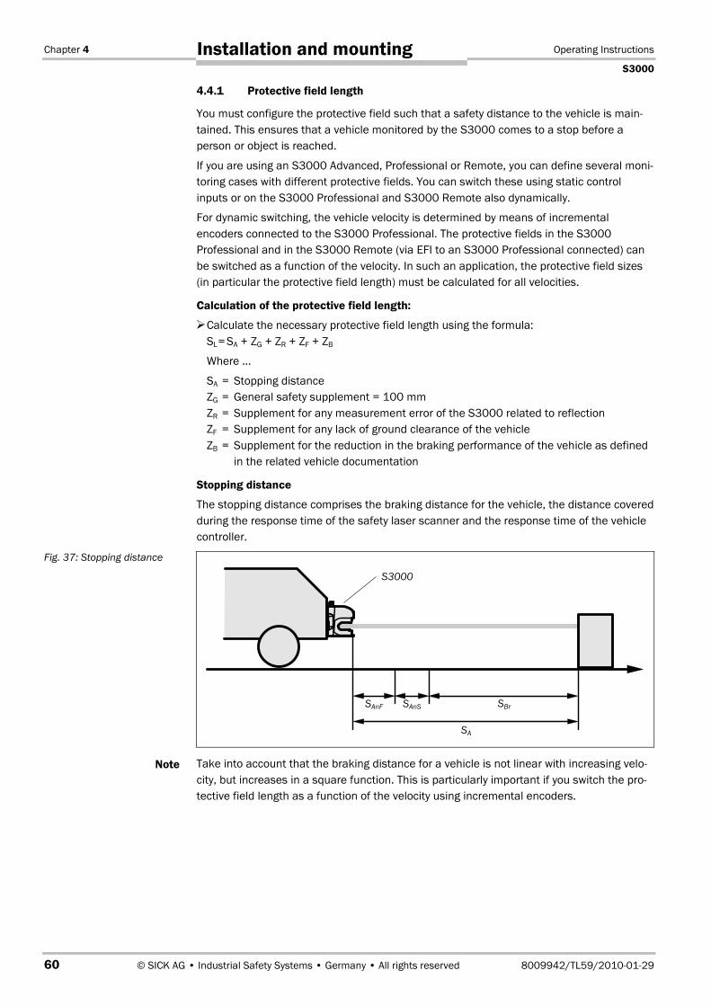
Chapter 4 Operating Instructions
S3000
60 © SICK AG • Industrial Safety Systems • Germany • All rights reserved 8009942/TL59/2010-01-29
Installation and mounting
4.4.1 Protective field length
You must configure the protective field such that a safety distance to the vehicle is main-tained. This ensures that a vehicle monitored by the S3000 comes to a stop before aperson or object is reached.
If you are using an S3000 Advanced, Professional or Remote, you can define several moni-toring cases with different protective fields. You can switch these using static controlinputs or on the S3000 Professional and S3000 Remote also dynamically.
For dynamic switching, the vehicle velocity is determined by means of incrementalencoders connected to the S3000 Professional. The protective fields in the S3000Professional and in the S3000 Remote (via EFI to an S3000 Professional connected) canbe switched as a function of the velocity. In such an application, the protective field sizes(in particular the protective field length) must be calculated for all velocities.
Calculation of the protective field length:
Calculate the necessary protective field length using the formula:SL= SA + ZG + ZR + ZF + ZB
Where …
SA = Stopping distanceZG = General safety supplement = 100 mmZR = Supplement for any measurement error of the S3000 related to reflectionZF = Supplement for any lack of ground clearance of the vehicleZB = Supplement for the reduction in the braking performance of the vehicle as defined
in the related vehicle documentation
Stopping distance
The stopping distance comprises the braking distance for the vehicle, the distance coveredduring the response time of the safety laser scanner and the response time of the vehiclecontroller.
Take into account that the braking distance for a vehicle is not linear with increasing velo-city, but increases in a square function. This is particularly important if you switch the pro-tective field length as a function of the velocity using incremental encoders.
Fig. 37: Stopping distance
Note
SAnF SBr
SA
S3000
SAnS
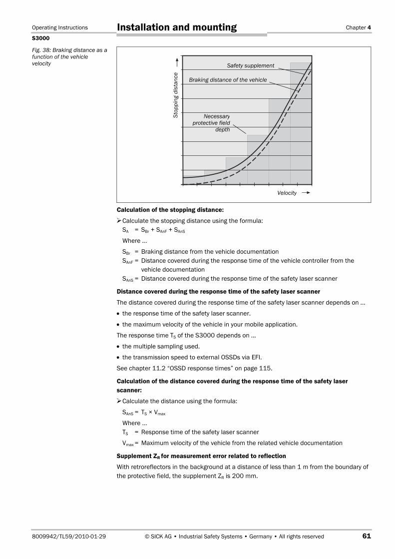
Operating Instructions Chapter 4
S3000
8009942/TL59/2010-01-29 © SICK AG • Industrial Safety Systems • Germany • All rights reserved 61
Installation and mounting
Calculation of the stopping distance:
Calculate the stopping distance using the formula:SA = SBr + SAnF + SAnS
Where …
SBr = Braking distance from the vehicle documentationSAnF = Distance covered during the response time of the vehicle controller from the
vehicle documentationSAnS = Distance covered during the response time of the safety laser scanner
Distance covered during the response time of the safety laser scanner
The distance covered during the response time of the safety laser scanner depends on …
• the response time of the safety laser scanner.
• the maximum velocity of the vehicle in your mobile application.
The response time TS of the S3000 depends on …
• the multiple sampling used.
• the transmission speed to external OSSDs via EFI.
See chapter 11.2 “OSSD response times” on page 115.
Calculation of the distance covered during the response time of the safety laserscanner:
Calculate the distance using the formula:
SAnS = TS × Vmax
Where …TS = Response time of the safety laser scanner
Vmax = Maximum velocity of the vehicle from the related vehicle documentation
Supplement ZR for measurement error related to reflection
With retroreflectors in the background at a distance of less than 1 m from the boundary ofthe protective field, the supplement ZR is 200 mm.
Fig. 38: Braking distance as afunction of the vehiclevelocity
Necessaryprotective field
depth
Braking distance of the vehicle
Safety supplement
Velocity
Stop
ping
dist
ance

Chapter 4 Operating Instructions
S3000
62 © SICK AG • Industrial Safety Systems • Germany • All rights reserved 8009942/TL59/2010-01-29
Installation and mounting
Supplement due to lack of ground clearance
This supplement is necessary because a person is generally detected above the foot andthe braking action can therefore not take into account the length of the foot in front of thedetection point. If a vehicle has no ground clearance, a person may receive foot injuries.
The supplement for foot space below 120 mm is 150 mm. If you wish to further reducethis supplement, read the supplement necessary from the following diagram:
Fig. 39: Supplement due tolack of ground clearance
Fig. 40: Diagram of groundclearance of the vehicle
0 50 100 150Supplement ZF in mm
50
60
120
Gro
und
clea
ranc
eof
the
vehi
cle
Ground clearance
Protective field length ZF
S3000

Operating Instructions Chapter 4
S3000
8009942/TL59/2010-01-29 © SICK AG • Industrial Safety Systems • Germany • All rights reserved 63
Installation and mounting
4.4.2 Protective field width
The width of the protective field must take into account the width of the vehicle, thesupplements for the measurement error and the lack of ground clearance.
Calculation of the protective field width:
Calculate the protective field width SB using the formula:SB = FB + 2 × (ZG + ZR + ZF)
Where …FB = Vehicle widthZG = General safety supplement = 100 mmZR = Supplement for any measurement error of the S3000 related to reflectionZF = Supplement for any lack of ground clearance of the vehicle
Normally you will mount the S3000 in the middle of the vehicle �. If this is not the case,then you must define the protective field asymmetrically �. (The CDS represents the fieldsas they appear in the top view on the scanner.) Ensure that there are supplements on theright and left of the vehicle �.
4.4.3 Height of the scan plane
Mount the S3000 such that the scan plane is at a maximum height of 200 mm!
Any body lying flat on the floor will be reliably detected. Tilting the protective field, whichwill result in objects with a diameter of 200 mm not being detected, is not allowed. We re-commend aligning the scan plane at 150 mm.
Fig. 41: Protective field width
Note
WARNING
Fig. 42: Mounting height
Max. 272 mm
Protective fieldlength set
150 mm
��
�
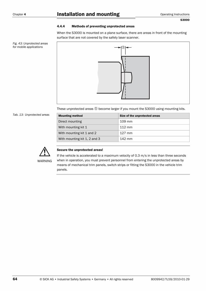
Chapter 4 Operating Instructions
S3000
64 © SICK AG • Industrial Safety Systems • Germany • All rights reserved 8009942/TL59/2010-01-29
Installation and mounting
4.4.4 Methods of preventing unprotected areas
When the S3000 is mounted on a plane surface, there are areas in front of the mountingsurface that are not covered by the safety laser scanner.
These unprotected areas � become larger if you mount the S3000 using mounting kits.
Mounting method Size of the unprotected areas
Direct mounting 109 mm
With mounting kit 1 112 mm
With mounting kit 1 and 2 127 mm
With mounting kit 1, 2 and 3 142 mm
Secure the unprotected areas!
If the vehicle is accelerated to a maximum velocity of 0.3 m/s in less than three secondswhen in operation, you must prevent personnel from entering the unprotected areas bymeans of mechanical trim panels, switch strips or fitting the S3000 in the vehicle trimpanels.
Fig. 43: Unprotected areasfor mobile applications
Tab. 13: Unprotected areas
WARNING
�
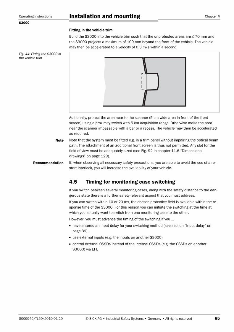
Operating Instructions Chapter 4
S3000
8009942/TL59/2010-01-29 © SICK AG • Industrial Safety Systems • Germany • All rights reserved 65
Installation and mounting
Fitting in the vehicle trim
Build the S3000 into the vehicle trim such that the unprotected areas are ≤ 70 mm andthe S3000 projects a maximum of 109 mm beyond the front of the vehicle. The vehiclemay then be accelerated to a velocity of 0.3 m/s within a second.
Aditionally, protect the area near to the scanner (5 cm wide area in front of the frontscreen) using a proximity switch with 5 cm acquisition range. Otherwise make the areanear the scanner impassable with a bar or a recess. The vehicle may then be acceleratedas required.
Note that the system must be fitted e.g. in a trim panel without impairing the optical beampath. The attachment of an additional front screen is thus not permitted. Any slot for thefield of view must be adequately sized (see Fig. 92 in chapter 11.6 “Dimensionaldrawings” on page 129).
If, when observing all necessary safety precautions, you are able to avoid the use of a re-start interlock, you will increase the availability of your vehicle.
4.5 Timing for monitoring case switchingIf you switch between several monitoring cases, along with the safety distance to the dan-gerous state there is a further safety-relevant aspect that you must address.
If you can switch within 10 or 20 ms, the chosen protective field is available within the re-sponse time of the S3000. For this reason you can initiate the switching at the time atwhich you actually want to switch from one monitoring case to the other.
However, you must advance the timing of the switching if you …
• have entered an input delay for your switching method (see section “Input delay” onpage 39).
• use external inputs (e.g. the inputs on another S3000).
• control external OSSDs instead of the internal OSSDs (e.g. the OSSDs on anotherS3000) via EFI.
Fig. 44: Fitting the S3000 inthe vehicle trim
Note
Recommendation

Chapter 4 Operating Instructions
S3000
66 © SICK AG • Industrial Safety Systems • Germany • All rights reserved 8009942/TL59/2010-01-29
Installation and mounting
The following diagram shows the relationships:
• If the input conditions are present at the control inputs within 10 or 20 ms (cf. �), thetiming for the switching (tUF) does not need to be advanced.
• If an input delay for the control inputs needs to be taken into account (cf. �), the timingfor the switching (tUFVz2) must be advanced by the input delay.
• If the inputs on a different device are used via EFI, the timing for the switching (tUFVz3)must be further advanced by 0.5 times the basic response time (= 30 or 60 ms) (cf. �).On a system with two S3000 use the scanner with the higher response time for the basisfor the calculation.
• If external OSSDs are used, the timing for the switching (tUFVz4) must be further advancedby 20 ms (cf. �).
Define the timing for the switching such that the S3000 already detects a person in theprotective field before the dangerous state occurs!
At the time of the switching there may be personnel in the protective field. Only by meansof switching in the correct time frame (i.e. before the hazard occurs at this point for theperson) is protection provided.
• In the phases before and after the switching, the safety distances calculated for the indi-vidual monitoring cases apply on their own.
• The considerations above serve only for the selection of the optimal timing of the switch-ing.
• If the timing for the switching cannot be exactly defined, e.g. due to the variable pro-cessing speed of the machine, or if advancing of the timing results in prematuretermination of the monitoring of the initial area, you must …– allow the two protective fields to partially overlap.– have both hazardous areas monitored temporarily using simultaneous monitoring.
Fig. 45: Advancement for theswitch timing
WARNING
Note
�
tUFtUFVz2tUFVz3tUFVz4
�
�
�
t

Operating Instructions Chapter 4
S3000
8009942/TL59/2010-01-29 © SICK AG • Industrial Safety Systems • Germany • All rights reserved 67
Installation and mounting
The following figure shows an example for a gantry robot that is protected using two moni-toring cases.
The gantry robot � moves to the right �. On the left hand side the dangerous movementis monitored by a monitoring case �. When the gantry robot arrives at the point tUv, switch-ing must have already been performed due to the advancing of the switching necessary sothat at time tU the right monitoring case � is active.
For the movement to the left, that is for the switching to the monitoring case �, the sameapplies.
How far you must advance the timing for the switching depends on …
• the input delay your switching method requires to provide the input condition for caseswitching (see section “Input delay” on page 39).
• whether you switch external OSSDs via EFI.
• whether you use external control inputs (e.g. on another S3000).
Calculation of the timing for the switching:
Calculate the timing for the switching using the following formula:
tUFVz = tEVz + texOVz + tStVz
Where …
tUFVz = Timing advance for the switching
tEVz = Input delay for the control inputs
texOVz = Delay due to external OSSDs over EFI = 20 ms
tStVz = Delay due to external control inputs over EFI (0.5 × basic response time)
Fig. 46: Example of advan-cing the timing for theswitching
Note
�
�
� �
tUv tU∆t

Chapter 4 Operating Instructions
S3000
68 © SICK AG • Industrial Safety Systems • Germany • All rights reserved 8009942/TL59/2010-01-29
Installation and mounting
4.6 Mounting steps
Special features to note during mounting:
Mount the S3000 such that it is protected from moisture, dirt and damage.
Ensure that the front screen field of view is not restricted.
Mount the scanner such that the indicators are easy to see.
Always mount the S3000 such that you can plug in and remove the system plug.
Avoid excessive shock and vibration loading on the safety laser scanner.
On applications that suffer from heavy vibration, prevent the fixing screws from comingloose using screw locking devices.
Regularly check the tightness of the fixing screws.
Prevent personnel from being able to crawl beneath, stand behind or climb over the pro-tective field by means of appropriate mounting of the S3000.
The origin of the scan plane is 63 mm above the bottom edge of the S3000. If you mountthe S3000 using mounting kit 3, then the origin of the scan plane is 102 mm above thebottom edge of mounting kit 3 (see chapter 11.6.3 “Scan plane origin” on page 131).
There are four possible ways of fixing the S3000:
• direct mounting without mounting kit
• mounting with mounting kit 1
• mounting with mounting kit 1 and 2
• mounting with mounting kit 1, 2, and 3
The mounting kits build one on another. For fixing with mounting kit 2 you will thereforealso need mounting kit 1. For fixing with mounting kit 3 you will therefore also need mount-ing kits 1 and 2. You will find the part numbers for the mounting kits in chapter 12.3.3“Mounting kits” on page 133.
WARNING
Fig. 47: Prevent crawlingbeneath, standing behind,climbing over
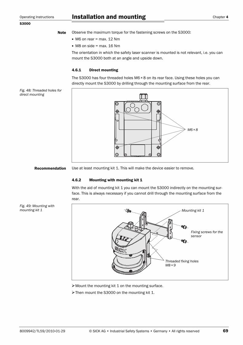
Operating Instructions Chapter 4
S3000
8009942/TL59/2010-01-29 © SICK AG • Industrial Safety Systems • Germany • All rights reserved 69
Installation and mounting
Observe the maximum torque for the fastening screws on the S3000:
M6 on rear = max. 12 Nm
M8 on side = max. 16 Nm
The orientation in which the safety laser scanner is mounted is not relevant, i.e. you canmount the S3000 both at an angle and upside down.
4.6.1 Direct mounting
The S3000 has four threaded holes M6�×8 on its rear face. Using these holes you candirectly mount the S3000 by drilling through the mounting surface from the rear.
Use at least mounting kit 1. This will make the device easier to remove.
4.6.2 Mounting with mounting kit 1
With the aid of mounting kit 1 you can mount the S3000 indirectly on the mounting sur-face. This is always necessary if you cannot drill through the mounting surface from therear.
Mount the mounting kit 1 on the mounting surface.
Then mount the S3000 on the mounting kit 1.
Note
Fig. 48: Threaded holes fordirect mounting
Recommendation
Fig. 49: Mounting withmounting kit 1
M6×8
Fixing screws for thesensor
Threaded fixing holesM8�×9
Mounting kit 1
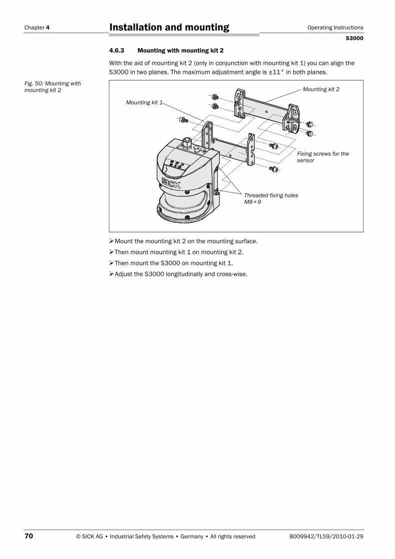
Chapter 4 Operating Instructions
S3000
70 © SICK AG • Industrial Safety Systems • Germany • All rights reserved 8009942/TL59/2010-01-29
Installation and mounting
4.6.3 Mounting with mounting kit 2
With the aid of mounting kit 2 (only in conjunction with mounting kit 1) you can align theS3000 in two planes. The maximum adjustment angle is ±11° in both planes.
Mount the mounting kit 2 on the mounting surface.
Then mount mounting kit 1 on mounting kit 2.
Then mount the S3000 on mounting kit 1.
Adjust the S3000 longitudinally and cross-wise.
Fig. 50: Mounting withmounting kit 2
Threaded fixing holesM8�×9
Fixing screws for thesensor
Mounting kit 1
Mounting kit 2
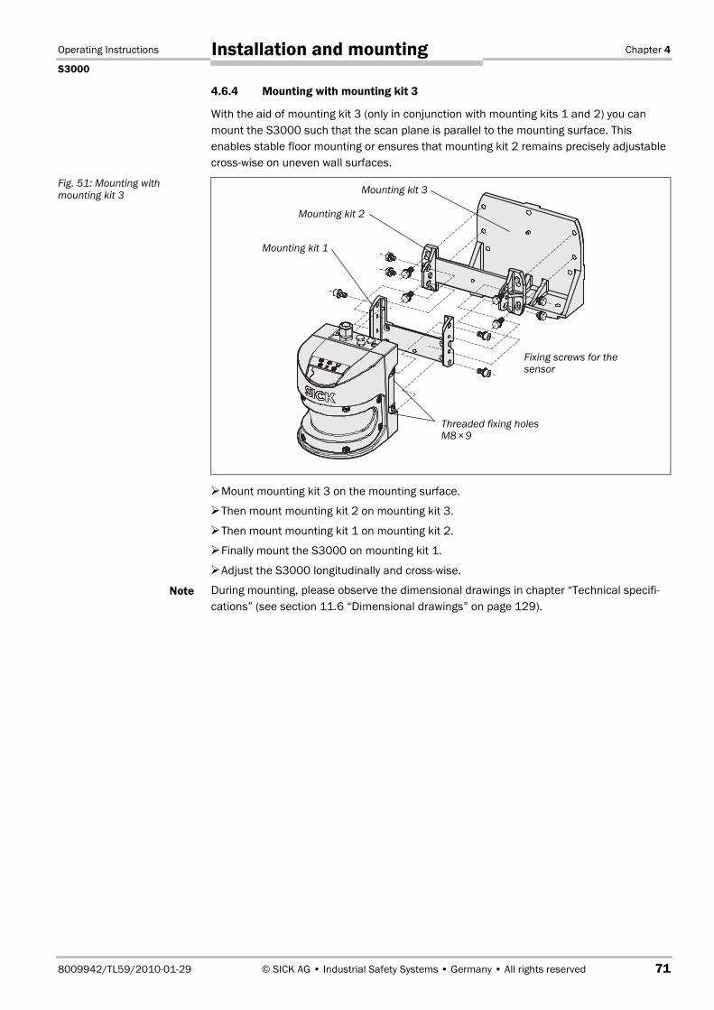
Operating Instructions Chapter 4
S3000
8009942/TL59/2010-01-29 © SICK AG • Industrial Safety Systems • Germany • All rights reserved 71
Installation and mounting
4.6.4 Mounting with mounting kit 3
With the aid of mounting kit 3 (only in conjunction with mounting kits 1 and 2) you canmount the S3000 such that the scan plane is parallel to the mounting surface. Thisenables stable floor mounting or ensures that mounting kit 2 remains precisely adjustablecross-wise on uneven wall surfaces.
Mount mounting kit 3 on the mounting surface.
Then mount mounting kit 2 on mounting kit 3.
Then mount mounting kit 1 on mounting kit 2.
Finally mount the S3000 on mounting kit 1.
Adjust the S3000 longitudinally and cross-wise.
During mounting, please observe the dimensional drawings in chapter “Technical specifi-cations” (see section 11.6 “Dimensional drawings” on page 129).
Fig. 51: Mounting withmounting kit 3
Note
Threaded fixing holesM8�×9
Mounting kit 1
Fixing screws for thesensor
Mounting kit 2
Mounting kit 3
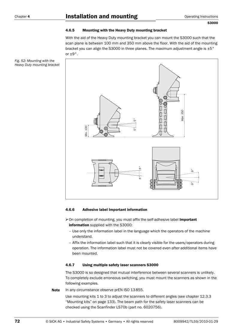
Chapter 4 Operating Instructions
S3000
72 © SICK AG • Industrial Safety Systems • Germany • All rights reserved 8009942/TL59/2010-01-29
Installation and mounting
4.6.5 Mounting with the Heavy Duty mounting bracket
With the aid of the Heavy Duty mounting bracket you can mount the S3000 such that thescan plane is between 100 mm and 350 mm above the floor. With the aid of the mountingbracket you can align the S3000 in three planes. The maximum adjustment angle is ±5°or ±9°.
4.6.6 Adhesive label Important information
On completion of mounting, you must affix the self-adhesive label Importantinformation supplied with the S3000:– Use only the information label in the language which the operators of the machine
understand.– Affix the information label such that it is clearly visible for the users/operators during
operation. The information label must not be covered even after additional items havebeen mounted.
4.6.7 Using multiple safety laser scanners S3000
The S3000 is so designed that mutual interference between several scanners is unlikely.To completely exclude erroneous switching, you must mount the scanners as shown in thefollowing examples.
In any circumstance observe prEN ISO 13�855.
Use mounting kits 1 to 3 to adjust the scanners to different angles (see chapter 12.3.3“Mounting kits” on page 133). The beam path for the safety laser scanners can bechecked using the Scanfinder LS70b (part no. 6020756).
Fig. 52: Mounting with theHeavy Duty mounting bracket
Note
9°9°
5°5°
5°5°
Min
.100
Max
.350
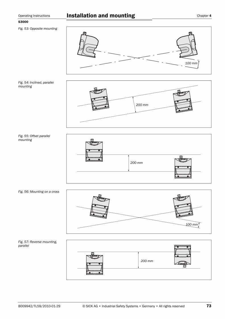
Operating Instructions Chapter 4
S3000
8009942/TL59/2010-01-29 © SICK AG • Industrial Safety Systems • Germany • All rights reserved 73
Installation and mounting
Fig. 53: Opposite mounting
Fig. 54: Inclined, parallelmounting
Fig. 55: Offset parallelmounting
Fig. 56: Mounting on a cross
Fig. 57: Reverse mounting,parallel
200 mm
200 mm
200 mm
100 mm
100 mm
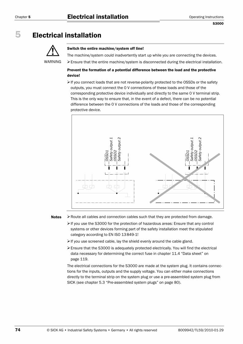
Chapter 5 Operating Instructions
S3000
74 © SICK AG • Industrial Safety Systems • Germany • All rights reserved 8009942/TL59/2010-01-29
Electrical installation
5 Electrical installation
Switch the entire machine/system off line!
The machine/system could inadvertently start up while you are connecting the devices.
Ensure that the entire machine/system is disconnected during the electrical installation.
Prevent the formation of a potential difference between the load and the protectivedevice!
If you connect loads that are not reverse-polarity protected to the OSSDs or the safetyoutputs, you must connect the 0 V connections of these loads and those of thecorresponding protective device individually and directly to the same 0 V terminal strip.This is the only way to ensure that, in the event of a defect, there can be no potentialdifference between the 0 V connections of the loads and those of the correspondingprotective device.
Route all cables and connection cables such that they are protected from damage.
If you use the S3000 for the protection of hazardous areas: Ensure that any controlsystems or other devices forming part of the safety installation meet the stipulatedcategory according to EN ISO 13�8491!
If you use screened cable, lay the shield evenly around the cable gland.
Ensure that the S3000 is adequately protected electrically. You will find the electricaldata necessary for determining the correct fuse in chapter 11.4 “Data sheet” onpage 119.
The electrical connections for the S3000 are made at the system plug. It contains connec-tions for the inputs, outputs and the supply voltage. You can either make connectionsdirectly to the terminal strip on the system plug or use a pre-assembled system plug fromSICK (see chapter 5.3 “Pre-assembled system plugs” on page 80).
WARNING
Notes
OSS
D1
Safe
tyou
tput
1O
SSD
2Sa
fety
outp
ut2
OSS
D1
Safe
tyou
tput
1O
SSD
2Sa
fety
outp
ut2

Operating Instructions Chapter 5
S3000
8009942/TL59/2010-01-29 © SICK AG • Industrial Safety Systems • Germany • All rights reserved 75
Electrical installation
5.1 System connectionAll inputs and output connections for the S3000 are located on the system connector. Thiscomprises of a 30pin screw terminal connector and is located in the system plug.
The system connection pin assignments vary depending on the S3000 variant.
• If the cable gland is missing or not tightened, or if fixing screws are missing or nottightened on the system plug, the IP 65 enclosure rating is not met.
• All inputs and outputs for the S3000 are to be used only in the context specified.
• If you want to operate two scanners in a group (communication via EFI), then the sameearthing method must be used for both scanners.
5.1.1 Pin assignments of the I/O modules
Pin Signal FunctionSt
anda
rd
Adva
nced
Prof
essi
onal
Prof
essi
onal
CMS
Rem
ote
1 +24V DC Supply voltage S3000 x x x x x
2 0V DC Supply voltage S3000 x x x x x
3 OSSD1 Output signal switching device x x x x x
4 OSSD2 Output signal switching device x x x x x
5 RESET Input, reset x x x x x
6 EDM Input, external device monitoring x x x x x
7 ERR Application diagnostic output —error/contamination or connection for ajumper for slave addressing7)
x x x x x
8 RES_REQ Output, reset required x x x x x
9 WF Output, object in warning field x x x x x
7) In master/slave operation, a device can be defined as a slave using a jumper between pin 7 and pin 10. Thisaction is also necessary if several safety laser scanners are connected to one EFI string on a safety controllerFlexi Soft.
Fig. 58: Screw terminal stripon the system plug
Note
Tab. 14: Pin assignments ofthe I/O modules

Chapter 5 Operating Instructions
S3000
76 © SICK AG • Industrial Safety Systems • Germany • All rights reserved 8009942/TL59/2010-01-29
Electrical installation
Pin Signal Function
Stan
dard
Adva
nced
Prof
essi
onal
Prof
essi
onal
CMS
Rem
ote
10 A1 Static control input A or connection for ajumper for slave addressing7)
x8) x x x X8)
11 A2 Static control input A x x x
12 B1 Static control input B x x x
13 B2 Static control input B x x x
14 EFIA x x x x x
15 EFIB
Enhanced function interface = safe SICKdevice communication x x x x x
16 +24V DC x x
17 GNDSupply voltage incremental encoder 1
x x
18 C1 orINC1_0
Static control input C or dynamic controlinput (incremental encoder input) 1
x x
19 D1 orINC1_90
Static control input D or dynamic controlinput (incremental encoder input) 1
x x
20 +24V DC x x
21 GNDSupply voltage incremental encoder 2
x x
22 C2 orINC2_0
Static control input C or dynamic controlinput (incremental encoder input) 2
x x
23 D2 orINC2_90
Static control input D or dynamic controlinput (incremental encoder input) 2
x x
24 Reserved, do not use!
25 RxD– x x x x x
26 RxD+ x x x x x
27 TxD+ x x x x x
28 TxD–
RS422 interface for output of measureddata
x x x x x
29 EFIA x x x x x
30 EFIB
Enhanced function interface = safe SICKdevice communication x x x x x
8) No control input A on S3000 Standard and Remote.

Operating Instructions Chapter 5
S3000
8009942/TL59/2010-01-29 © SICK AG • Industrial Safety Systems • Germany • All rights reserved 77
Electrical installation
Incremental encoder specification
Never supply both incremental encoders using one supply cable!
The connection cables for the incremental encoders must each be in a separate plastic-sheathed cable as otherwise a cable break could cause an error that could remain un-detected.
The incremental encoders must meet the following specifications:
• two-channel rotary encoder with 90° phase offset
• supply voltage: 24 V DC
• outputs: push/pull outputs
• enclosure rating IP 54 or better
• screened cable
• max. pulse frequency: 100 kHz
• min. number of pulses: 50 pulses per cm
You can procure suitable incremental encoders, e.g., from SICK-Stegmann GmbH,Duerrheimer Strasse 36, 78166 Donaueschingen,www.sick.de/de/products/categories/industrial/encoder/en.html.Recommended series: DGS60-G, DGS65-G or DGS66-G.
EFI connection
Connect EFI-A on the first device with EFI-A on the second device and EFI-B on the firstdevice with EFI-B on the second device.
• Always use screened twisted pair cables!
• If the length of the cable to the safety laser scanner is more than 30 m, the shield is tobe connected as close as possible to the safety laser scanner.
WARNING
Recommendation
Notes
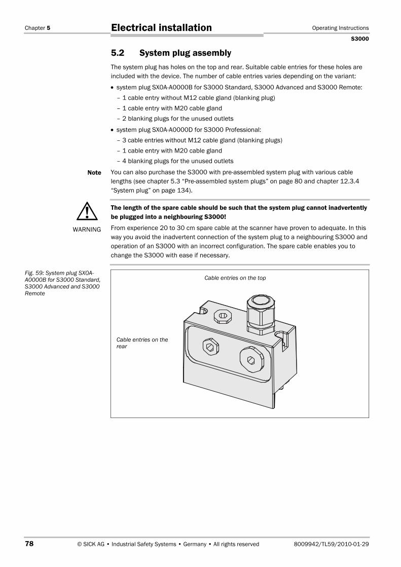
Chapter 5 Operating Instructions
S3000
78 © SICK AG • Industrial Safety Systems • Germany • All rights reserved 8009942/TL59/2010-01-29
Electrical installation
5.2 System plug assemblyThe system plug has holes on the top and rear. Suitable cable entries for these holes areincluded with the device. The number of cable entries varies depending on the variant:
• system plug SX0A-A0000B for S3000 Standard, S3000 Advanced and S3000 Remote:– 1 cable entry without M12 cable gland (blanking plug)– 1 cable entry with M20 cable gland– 2 blanking plugs for the unused outlets
• system plug SX0A-A0000D for S3000 Professional:– 3 cable entries without M12 cable gland (blanking plugs)– 1 cable entry with M20 cable gland– 4 blanking plugs for the unused outlets
You can also purchase the S3000 with pre-assembled system plug with various cablelengths (see chapter 5.3 “Pre-assembled system plugs” on page 80 and chapter 12.3.4“System plug” on page 134).
The length of the spare cable should be such that the system plug cannot inadvertentlybe plugged into a neighbouring S3000!
From experience 20 to 30 cm spare cable at the scanner have proven to adequate. In thisway you avoid the inadvertent connection of the system plug to a neighbouring S3000 andoperation of an S3000 with an incorrect configuration. The spare cable enables you tochange the S3000 with ease if necessary.
Note
WARNING
Fig. 59: System plug SX0A-A0000B for S3000 Standard,S3000 Advanced and S3000Remote
Cable entries on therear
Cable entries on the top
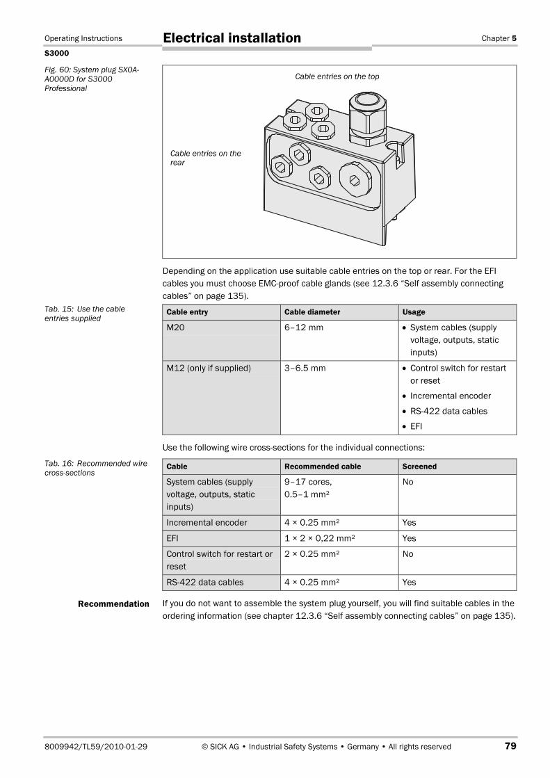
Operating Instructions Chapter 5
S3000
8009942/TL59/2010-01-29 © SICK AG • Industrial Safety Systems • Germany • All rights reserved 79
Electrical installation
Depending on the application use suitable cable entries on the top or rear. For the EFIcables you must choose EMC-proof cable glands (see 12.3.6 “Self assembly connectingcables” on page 135).
Cable entry Cable diameter Usage
M20 6–12 mm • System cables (supplyvoltage, outputs, staticinputs)
M12 (only if supplied) 3–6.5 mm • Control switch for restartor reset
• Incremental encoder
• RS422 data cables
• EFI
Use the following wire cross-sections for the individual connections:
Cable Recommended cable Screened
System cables (supplyvoltage, outputs, staticinputs)
9–17 cores,0.5–1 mm²
No
Incremental encoder 4 × 0.25 mm² Yes
EFI 1 × 2 × 0,22 mm² Yes
Control switch for restart orreset
2 × 0.25 mm² No
RS422 data cables 4 × 0.25 mm² Yes
If you do not want to assemble the system plug yourself, you will find suitable cables in theordering information (see chapter 12.3.6 “Self assembly connecting cables” on page 135).
Fig. 60: System plug SX0A-A0000D for S3000Professional
Tab. 15: Use the cableentries supplied
Tab. 16: Recommended wirecross-sections
Recommendation
Cable entries on therear
Cable entries on the top

Chapter 5 Operating Instructions
S3000
80 © SICK AG • Industrial Safety Systems • Germany • All rights reserved 8009942/TL59/2010-01-29
Electrical installation
5.3 Pre-assembled system plugs
5.3.1 Pre-assembled system plugs with flying leads
To connect the S3000 variants, the following pre-assembled system plugs are available(see also chapter 12.3.4 “System plug” on page 134):
• SX0A-B0905G– for S3000 Standard and S3000 Remote– with 9 unscreened cores– 5 m long
– cable outlet on the bottom
• SX0A-B0905B, SX0A-B0910B and SX0A-B0920B– for S3000 Standard and S3000 Remote– with 9 unscreened cores– 5, 10 or 20 m long
– cable outlet on the top
• SX0A-B1305B, SX0A-B1310B and SX0A-B1320B– for S3000 Advanced– with 13 unscreened cores– 5, 10 or 20 m long
– cable outlet on the top
• SX0A-B1305D and SX0A-B1310D– for S3000 Professional with static and dynamic inputs– with 13 unscreened cores– 5 or 10 m long– with 3 M12 cable entries for incremental encoders
– cable outlet on the top
• SX0A-B1705B, SX0A-B1710B and SX0A-B1720B– for S3000 Professional mit static inputs– with 17 unscreened cores– 5, 10 or 20 m long– cable outlet on the top
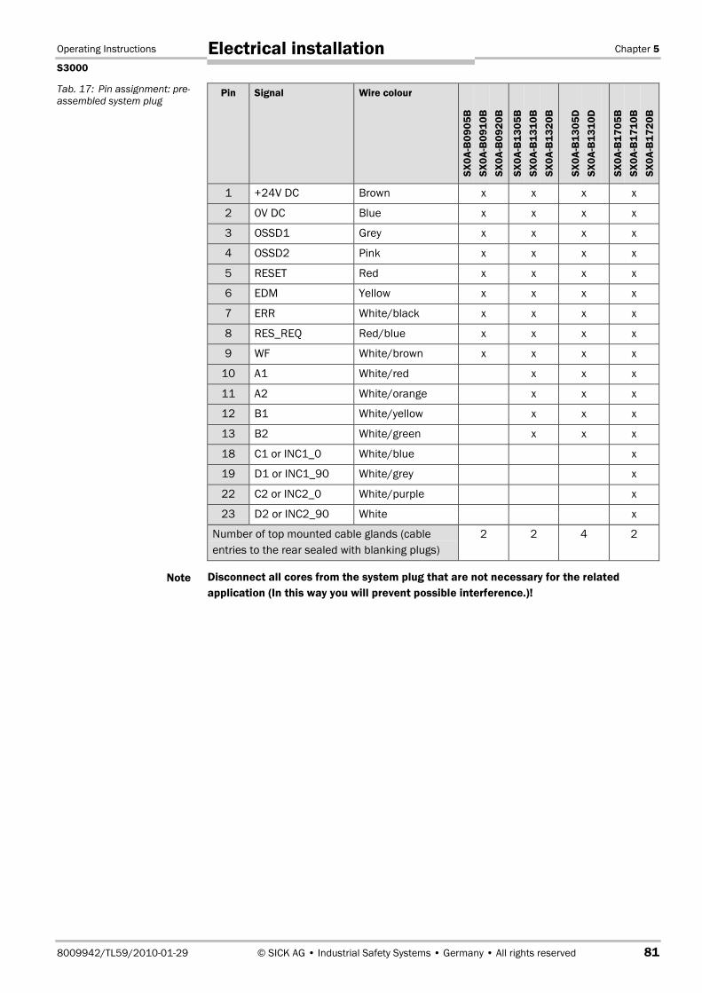
Operating Instructions Chapter 5
S3000
8009942/TL59/2010-01-29 © SICK AG • Industrial Safety Systems • Germany • All rights reserved 81
Electrical installation
Pin Signal Wire colour
SX0A
-B09
05B
SX0A
-B09
10B
SX0A
-B09
20B
SX0A
-B13
05B
SX0A
-B13
10B
SX0A
-B13
20B
SX0A
-B13
05D
SX0A
-B13
10D
SX0A
-B17
05B
SX0A
-B17
10B
SX0A
-B17
20B
1 +24V DC Brown x x x x
2 0V DC Blue x x x x
3 OSSD1 Grey x x x x
4 OSSD2 Pink x x x x
5 RESET Red x x x x
6 EDM Yellow x x x x
7 ERR White/black x x x x
8 RES_REQ Red/blue x x x x
9 WF White/brown x x x x
10 A1 White/red x x x
11 A2 White/orange x x x
12 B1 White/yellow x x x
13 B2 White/green x x x
18 C1 or INC1_0 White/blue x
19 D1 or INC1_90 White/grey x
22 C2 or INC2_0 White/purple x
23 D2 or INC2_90 White x
Number of top mounted cable glands (cableentries to the rear sealed with blanking plugs)
2 2 4 2
Disconnect all cores from the system plug that are not necessary for the relatedapplication (In this way you will prevent possible interference.)!
Tab. 17: Pin assignment: pre-assembled system plug
Note

Chapter 6 Operating Instructions
S3000
82 © SICK AG • Industrial Safety Systems • Germany • All rights reserved 8009942/TL59/2010-01-29
Application and connectiondiagrams
6 Application and connection diagramsThe examples shown are only provided as an aid for your planning. You may need to con-sider additional protection measures for your application.
In the examples with protective field switching, note that at the time of the switching theremay already be a person in the protective field. Only by means of switching in the correcttime frame (i.e. before the danger occurs at this point) is reliable protection provided (seechapter 4.5 “Timing for monitoring case switching” on page 65).
6.1 Stationary applications
6.1.1 Applications with one monitored area (S3000 Standard)
The area is permanently monitored by the S3000.
Fig. 61: Hazardous areaprotection with S3000Standard
S3000 Standard with oneprotective field and warningfield — mounted horizontally
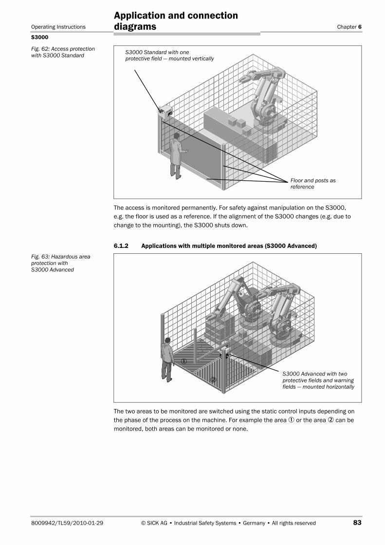
Operating Instructions Chapter 6
S3000
8009942/TL59/2010-01-29 © SICK AG • Industrial Safety Systems • Germany • All rights reserved 83
Application and connectiondiagrams
The access is monitored permanently. For safety against manipulation on the S3000,e.g. the floor is used as a reference. If the alignment of the S3000 changes (e.g. due tochange to the mounting), the S3000 shuts down.
6.1.2 Applications with multiple monitored areas (S3000 Advanced)
The two areas to be monitored are switched using the static control inputs depending onthe phase of the process on the machine. For example the area � or the area � can bemonitored, both areas can be monitored or none.
Fig. 62: Access protectionwith S3000 Standard
Fig. 63: Hazardous areaprotection withS3000 Advanced
S3000 Advanced with twoprotective fields and warningfields — mounted horizontally
�
�
S3000 Standard with oneprotective field — mounted vertically
Floor and posts asreference

Chapter 6 Operating Instructions
S3000
84 © SICK AG • Industrial Safety Systems • Germany • All rights reserved 8009942/TL59/2010-01-29
Application and connectiondiagrams
The two areas to be monitored are switched using the static control inputs depending onthe process phase. For example the area � or the area � can be monitored, both areascan be monitored or none. For safety against manipulation on the S3000, e.g. the floor isused as a reference in each case. If the alignment of the S3000 changes (e.g. due tochange to the mounting), the S3000 shuts down.
6.2 Mobile applications
6.2.1 Vehicle monitoring for unidirectional travel (S3000 Standard)
The S3000 monitors the area in one direction of travel and stops the vehicle as soon asthere is an object in the protective field.
Fig. 64: Access protectionwith S3000 Advanced
Fig. 65: Vehicle monitoringwith S3000 Standard
�
�
S3000 Advanced with twoprotective fields — mountedvertically
Floor as reference
S3000 Standard withone protective field andwarning field

Operating Instructions Chapter 6
S3000
8009942/TL59/2010-01-29 © SICK AG • Industrial Safety Systems • Germany • All rights reserved 85
Application and connectiondiagrams
6.2.2 Velocity-dependent vehicle monitoring for unidirectional travel(S3000 Professional)
Using incremental encoders the S3000 Professional acquires the velocity of the vehicle viaits dynamic control inputs. For different velocities, various field sets with protective fieldsand warning fields of varying sizes are configured in the S3000. The field sets are switcheddynamically using the vehicle velocity.
6.2.3 Vehicle monitoring with determination of the surrounding contour andreflector detection (S3000 Professional CMS)
The S3000 monitors the area in one direction of travel and stops the vehicle as soon asthere is an object in the protective field. In addition, the surrounding contour is measuredand reflectors fitted to the walls detected. Surrounding contour and reflector detection areoutput via the RS422 interface using configurable messages.
Fig. 66: Velocity-dependentvehicle monitoring withS3000 Professional
Fig. 67: Mobile applicationwith S3000 ProfessionalCMS
S3000 Professional
Incremental encoder
S3000 Professional CMS
ReflectorsWarning field
Protective field
Surrounding contour

Chapter 6 Operating Instructions
S3000
86 © SICK AG • Industrial Safety Systems • Germany • All rights reserved 8009942/TL59/2010-01-29
Application and connectiondiagrams
6.2.4 Velocity-dependent vehicle monitoring for bi-directional travel(S3000 Professional with S3000 Remote)
Using incremental encoders the S3000 Professional acquires the velocity of the vehicle viaits dynamic control inputs. Various field sets of different sizes are configured in the S3000for the different velocities. The field sets are switched dynamically using the vehiclevelocity.
The S3000 Remote receives the values from the incremental encoders from the S3000Professional via the EFI. It monitors the areas for the second direction of travel as a func-tion of the velocity. As soon as there is an object in the protective field, the S3000 Remotedeactivates the OSSDs on the S3000 Professional using the EFI.
Fig. 68: Mobile applicationwith S3000 Professional
S3000 Professional
Incremental encoder
S3000 Remote
EFI connection

Operating Instructions Chapter 6
S3000
8009942/TL59/2010-01-29 © SICK AG • Industrial Safety Systems • Germany • All rights reserved 87
Application and connectiondiagrams
6.2.5 Vehicle monitoring with four safety laser scanners and the Flexi Soft modularsafety controller
The protective fields on the two S3000 monitor in the related direction of travel on forwardor reverse movement. The protective fields on the S300 monitor the area to the side of thevehicle. The information on the protective fields is passed via EFI to the safety controllerFlexi Soft and there combined using logic modules.
The signal on the safety outputs on the safety controller Flexi Soft is passed to the vehiclecontrol.
6.3 Applications with sens:ControlWith sens:Control, the safe control solutions, SICK provides you with an entire range ofinterface products that were specially developed for interfacing safety products andmachines.
For complex applications the S3000 can be integrated into sens:Control family safetysystems. In this way the functions of the laser scanner can be enhanced andcorresponding applications realised.
Please observe the related operating instructions for the sens:Control products.
Fig. 69: Mobile applicationwith S3000 and S300Advanced
Note
S3000 Advanced
S300 Advanced
S3000 Advanced
S300 Advanced
Flexi Soft
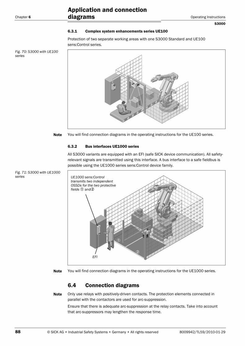
Chapter 6 Operating Instructions
S3000
88 © SICK AG • Industrial Safety Systems • Germany • All rights reserved 8009942/TL59/2010-01-29
Application and connectiondiagrams
6.3.1 Complex system enhancements series UE100
Protection of two separate working areas with one S3000 Standard and UE100sens:Control series.
You will find connection diagrams in the operating instructions for the UE100 series.
6.3.2 Bus interfaces UE1000 series
All S3000 variants are equipped with an EFI (safe SICK device communication). All safety-relevant signals are transmitted using this interface. A bus interface to a safe fieldbus ispossible using the UE1000 series sens:Control device family.
You will find connection diagrams in the operating instructions for the UE1000 series.
6.4 Connection diagramsOnly use relays with positively-driven contacts. The protection elements connected inparallel with the contactors are used for arc-suppression.
Ensure that there is adequate arc-suppression at the relay contacts. Take into accountthat arc-suppressors may lengthen the response time.
Fig. 70: S3000 with UE100series
Note
Fig. 71: S3000 with UE1000series
Note
Note
UE1000 sens:Controltransmits two independentOSSDs for the two protectivefields � and�
�
�
EFI

Operating Instructions Chapter 6
S3000
8009942/TL59/2010-01-29 © SICK AG • Industrial Safety Systems • Germany • All rights reserved 89
Application and connectiondiagrams
If you require to operate two scanners in a group (communication via EFI), then the sameearthing method must be used for both scanners.
Sketch key
• 1) = output circuitsThese contacts are to be connected to the controller such that, with the output circuitopen, the dangerous state is disabled. For categories 3 and 4 in compliance withEN ISO 13�8491, the interfacing must be two-channel (x-/y paths). Observe themaximum values for the loading of the outputs (see chapter 11.4 “Data sheet” onpage 119).
• H2 = sensor for error/contamination
• H3 = sensor for waiting for restart
• H8 = sensor for warning field interruption
6.4.1 Restart interlock and external device monitoring
S3000 Standard in conjunction with relays/contactors; operating mode: with restart inter-lock and external device monitoring.
Fig. 72: Connection diagramsfor restart interlock andexternal device monitoring
S3000

Chapter 6 Operating Instructions
S3000
90 © SICK AG • Industrial Safety Systems • Germany • All rights reserved 8009942/TL59/2010-01-29
Application and connectiondiagrams
6.4.2 Restart interlock and external device monitoring with UE10 series
S3000 Standard in conjunction with UE10-3 OS; operating mode: with restart interlock andexternal device monitoring.
6.4.3 Protective field switching with two static inputs
S3000 Advanced in conjunction with relays/contactors; operating mode: with restart inter-lock and external device monitoring; protective field switching by means of control inputs A(In A) and B (In B).
Fig. 73: Connection diagramfor restart interlock andexternal device monitoringwith series UE10
Fig. 74: Connection diagramfor protective field switchingusing two static inputs
S3000
S3000
�

Operating Instructions Chapter 6
S3000
8009942/TL59/2010-01-29 © SICK AG • Industrial Safety Systems • Germany • All rights reserved 91
Application and connectiondiagrams
6.4.4 Protective field switching with four static inputs
S3000 Professional in conjunction with relays/contactors; operating mode: with restartinterlock and external device monitoring; static protective field switching by means of thecontrol inputs A (In A), B (In B), C (In C) and D (In D).
6.4.5 Protective field switching with static and dynamic inputs
S3000 Professional in conjunction with relays/contactors; operating mode: without restartinterlock with external device monitoring, dynamic protective field switching by means ofB1 and B2 as well as static protective field switching by means of control inputs A (In A)and B (In B).
Fig. 75: Connection diagramfor protective field switchingwith four static inputs
Fig. 76: Connection diagramfor protective field switchingwith static and dynamicinputs
S3000
S3000

Chapter 6 Operating Instructions
S3000
92 © SICK AG • Industrial Safety Systems • Germany • All rights reserved 8009942/TL59/2010-01-29
Application and connectiondiagrams
6.4.6 Protective field switching between two S3000 with static inputs
S3000 Advanced with S3000 Advanced in master/slave conjunction with relays/con-tactors; operating mode: without restart interlock with external device monitoring; pro-tective field switching by means of control input A (In A) and control input B (In B) onseparate OSSD pairs (simultaneous monitoring).
If you use two S3000 Advanced or two S3000 Professional in one application, then youcan only connect the input signals to one safety laser scanner. Distributed connection ofthe input signals to two safety laser scanners is not possible.
Fig. 77: Connection diagramfor protective field switchingbetween two S3000 withstatic inputs
Note
S3000 S3000
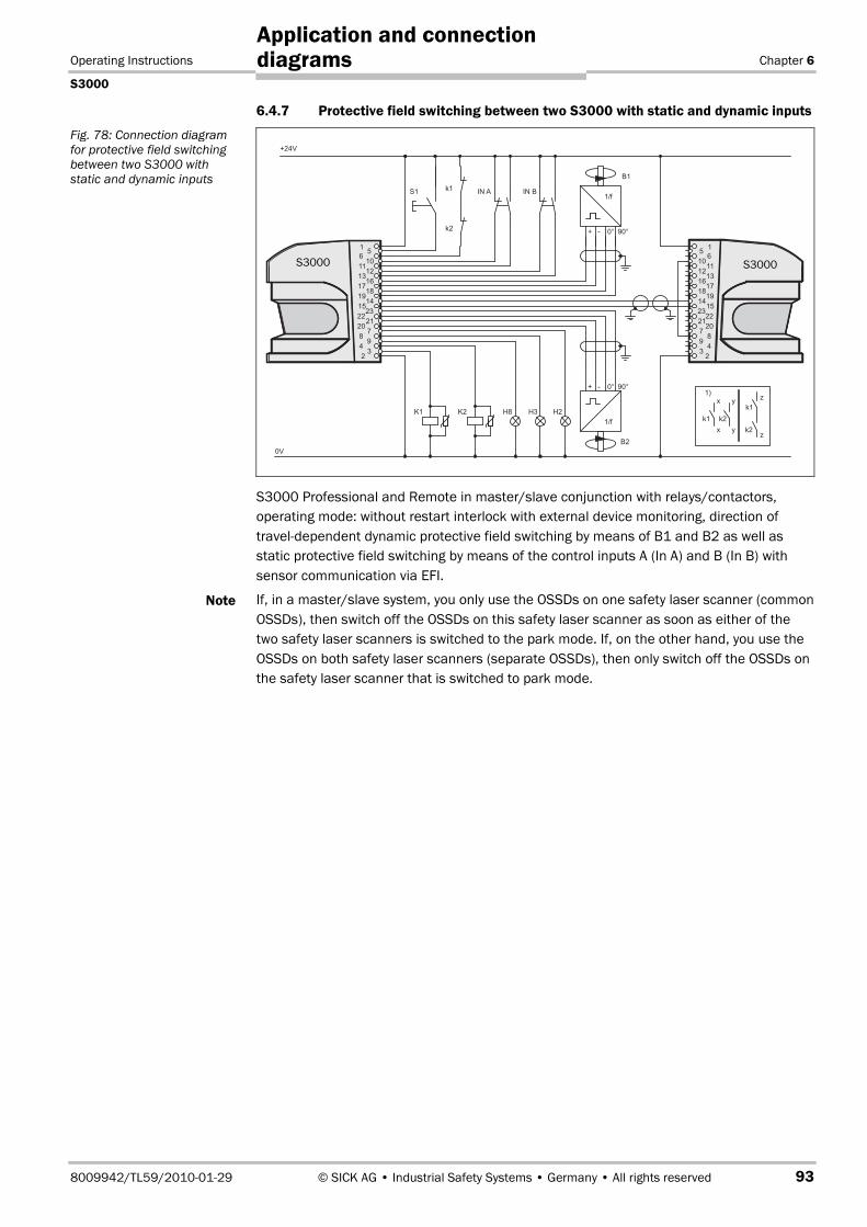
Operating Instructions Chapter 6
S3000
8009942/TL59/2010-01-29 © SICK AG • Industrial Safety Systems • Germany • All rights reserved 93
Application and connectiondiagrams
6.4.7 Protective field switching between two S3000 with static and dynamic inputs
S3000 Professional and Remote in master/slave conjunction with relays/contactors,operating mode: without restart interlock with external device monitoring, direction oftravel-dependent dynamic protective field switching by means of B1 and B2 as well asstatic protective field switching by means of the control inputs A (In A) and B (In B) withsensor communication via EFI.
If, in a master/slave system, you only use the OSSDs on one safety laser scanner (commonOSSDs), then switch off the OSSDs on this safety laser scanner as soon as either of thetwo safety laser scanners is switched to the park mode. If, on the other hand, you use theOSSDs on both safety laser scanners (separate OSSDs), then only switch off the OSSDs onthe safety laser scanner that is switched to park mode.
Fig. 78: Connection diagramfor protective field switchingbetween two S3000 withstatic and dynamic inputs
Note
S3000 S3000
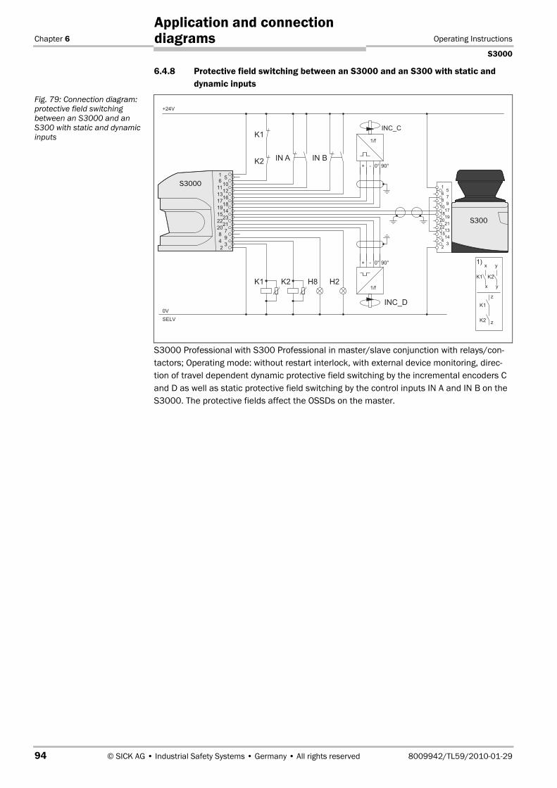
Chapter 6 Operating Instructions
S3000
94 © SICK AG • Industrial Safety Systems • Germany • All rights reserved 8009942/TL59/2010-01-29
Application and connectiondiagrams
6.4.8 Protective field switching between an S3000 and an S300 with static anddynamic inputs
S3000 Professional with S300 Professional in master/slave conjunction with relays/con-tactors; Operating mode: without restart interlock, with external device monitoring, direc-tion of travel dependent dynamic protective field switching by the incremental encoders Cand D as well as static protective field switching by the control inputs IN A and IN B on theS3000. The protective fields affect the OSSDs on the master.
Fig. 79: Connection diagram:protective field switchingbetween an S3000 and anS300 with static and dynamicinputs
S3000
S300

Operating Instructions Chapter 6
S3000
8009942/TL59/2010-01-29 © SICK AG • Industrial Safety Systems • Germany • All rights reserved 95
Application and connectiondiagrams
6.4.9 Protective field switching with a Flexi Soft safety controller
Two S3000 Professional with one S300 Professional in master/slave combination.Protective field evaluation and switching via EFI using a Flexi Soft safety controller.
One S3000 Professional with one S300 Professional in master/slave combination.Protective field evaluation and switching via EFI using a Flexi Soft safety controller.
Fig. 80: Connection diagram:protective field switchingbetween two S3000 using aFlexi Soft safety controller
Fig. 81: Connection diagram:protective field switchingbetween S3000 and S300using a Flexi Soft safetycontroller
S3000
FX3CPU0
FX3XTIO
S3000
Simplified representation
S300
S3000
FX3CPU0
FX3XTIO
Simplified representation
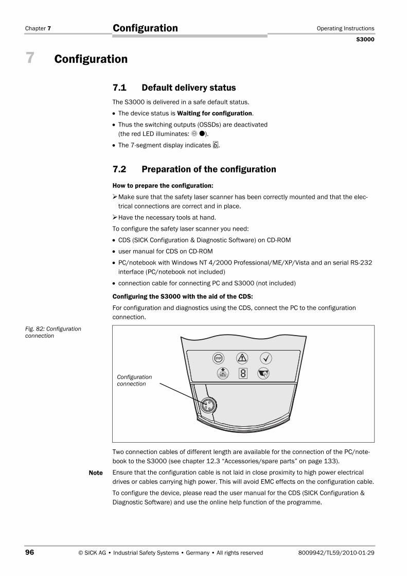
Chapter 7 Operating Instructions
S3000
96 © SICK AG • Industrial Safety Systems • Germany • All rights reserved 8009942/TL59/2010-01-29
Configuration
7 Configuration
7.1 Default delivery statusThe S3000 is delivered in a safe default status.
• The device status is Waiting for configuration.
• Thus the switching outputs (OSSDs) are deactivated(the red LED illuminates: ��).
• The 7segment display indicates �.
7.2 Preparation of the configuration
How to prepare the configuration:
Make sure that the safety laser scanner has been correctly mounted and that the elec-trical connections are correct and in place.
Have the necessary tools at hand.
To configure the safety laser scanner you need:
• CDS (SICK Configuration & Diagnostic Software) on CDROM
• user manual for CDS on CDROM
• PC/notebook with Windows NT 4/2000 Professional/ME/XP/Vista and an serial RS232interface (PC/notebook not included)
• connection cable for connecting PC and S3000 (not included)
Configuring the S3000 with the aid of the CDS:
For configuration and diagnostics using the CDS, connect the PC to the configurationconnection.
Two connection cables of different length are available for the connection of the PC/note-book to the S3000 (see chapter 12.3 “Accessories/spare parts” on page 133).
Ensure that the configuration cable is not laid in close proximity to high power electricaldrives or cables carrying high power. This will avoid EMC effects on the configuration cable.
To configure the device, please read the user manual for the CDS (SICK Configuration &Diagnostic Software) and use the online help function of the programme.
Fig. 82: Configurationconnection
Note
Configurationconnection
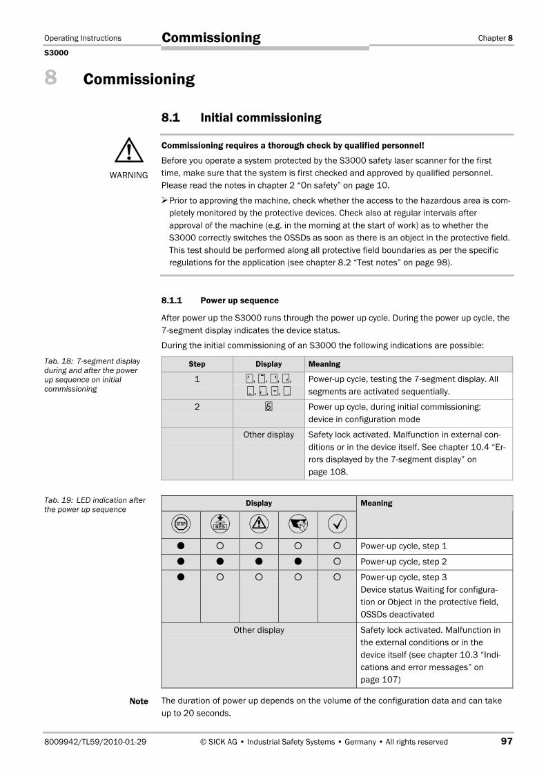
Operating Instructions Chapter 8
S3000
8009942/TL59/2010-01-29 © SICK AG • Industrial Safety Systems • Germany • All rights reserved 97
Commissioning
8 Commissioning
8.1 Initial commissioning
Commissioning requires a thorough check by qualified personnel!
Before you operate a system protected by the S3000 safety laser scanner for the firsttime, make sure that the system is first checked and approved by qualified personnel.Please read the notes in chapter 2 “On safety” on page 10.
Prior to approving the machine, check whether the access to the hazardous area is com-pletely monitored by the protective devices. Check also at regular intervals afterapproval of the machine (e.g. in the morning at the start of work) as to whether theS3000 correctly switches the OSSDs as soon as there is an object in the protective field.This test should be performed along all protective field boundaries as per the specificregulations for the application (see chapter 8.2 “Test notes” on page 98).
8.1.1 Power up sequence
After power up the S3000 runs through the power up cycle. During the power up cycle, the7segment display indicates the device status.
During the initial commissioning of an S3000 the following indications are possible:
Step Display Meaning
1 , , �, �, , �, �, �
Power-up cycle, testing the 7segment display. Allsegments are activated sequentially.
2 � Power up cycle, during initial commissioning:device in configuration mode
Other display Safety lock activated. Malfunction in external con-ditions or in the device itself. See chapter 10.4 “Er-rors displayed by the 7segment display” onpage 108.
Display
� � � � �Meaning
� � � � � Power-up cycle, step 1
� � � � � Power-up cycle, step 2
� � � � � Power-up cycle, step 3Device status Waiting for configura-tion or Object in the protective field,OSSDs deactivated
Other display Safety lock activated. Malfunction inthe external conditions or in thedevice itself (see chapter 10.3 “Indi-cations and error messages” onpage 107)
The duration of power up depends on the volume of the configuration data and can takeup to 20 seconds.
WARNING
Tab. 18: 7segment displayduring and after the powerup sequence on initialcommissioning
Tab. 19: LED indication afterthe power up sequence
Note
Chapter 8 Operating Instructions
S3000
98 © SICK AG • Industrial Safety Systems • Germany • All rights reserved 8009942/TL59/2010-01-29
Commissioning
8.2 Test notesThe purpose of the tests described in the following is to confirm the safety requirementsspecified in the national/international rules and regulations, especially the safetyrequirements in the Machine and Work Equipment Directive (EC Conformity).
These tests are also used to identify if the protection is affected by external light sourcesor other unusual ambient effects.
These tests must therefore always be performed.
8.2.1 Pre-commissioning tests
The purpose of the pre-commissioning tests is to confirm the safety requirementsspecified in the national/international rules and regulations (EC Conformity). This appliesparticularly to the safety requirements in the machinery directive or work equipmentdirective.
Ensure that you do not place anybody at risk during initial commissioning of themachine!
Always expect that the machine, plant or the protective device does not yet behave as youhave planned.
Ensure that there are no persons in the hazardous area during initial commissioning.
Check the effectiveness of the protective device mounted to the machine, using allselectable operating modes as specified in the checklist in the annex (see section 13.2“Manufacturer’s checklistManufacturer’s checklist” on page 139).
Make sure that the operating personnel of the machine protected by the safety laserscanner are properly instructed by specialist personnel before being allowed to operatethe machine. Instructing the operating personnel is the responsibility of the machineowner.
Ensure that the adhesive label Important information, which is included with the scan-ner on delivery, is affixed to the machine in a place where it is clearly visible for theoperators. Ensure that the operators have the possibility to perform this daily checkcorrectly.
The annex to this document includes a checklist for review by the manufacturer andOEM. Use this checklist as a reference prior to commissioning for the first time (see sec-tion 13.2 “Manufacturer’s checklistManufacturer’s checklist” on page 139).
Document the adjustment of the scanner and the results of the testing during initialcommissioning in a traceable manner. For this purpose also print out the complete con-figuration of the scanner (including protective field shapes) and include these with thedocumentation.
SICK AG can perform the testing prior to initial commissioning for you.
8.2.2 Regular inspection of the protective device by qualified personnel
Check the system following the inspection intervals specified in the national rules andregulations. This procedure ensures that any changes on the machine or manipulationsof the protective device after the first commissioning are detected.
If major changes have been made to the machine or the protective device, or if the safe-ty laser scanner has been modified or repaired, check the plant again as per the check-list in the annex (see section 13.2 “Manufacturer’s checklistManufacturer’s checklist”on page 139).
WARNING
Note

Operating Instructions Chapter 8
S3000
8009942/TL59/2010-01-29 © SICK AG • Industrial Safety Systems • Germany • All rights reserved 99
Commissioning
8.2.3 Daily testing of the protective device by a specialist or authorised personnel
The effectiveness of the protective device must be checked daily by a specialist or byauthorised personnel. The test must also be performed if the operating mode is changed.
No further operation if errors occur during the test!
If any one of the following points is not met, it is not permitted to continue to work on themachine or operate the vehicle. In this case the installation of the S3000 must be checkedby specialised personnel (see section 8.2.2 “Regular inspection of the protective device byqualified personnel” on page 98).
The test must be carried out for the relevant preset monitoring case.
Check the mechanical installation to ensure that all mounting screws are secure andthat the S3000 is properly aligned.
Check each S3000 device for visible changes such as damage, manipulation etc.
Switch on the machine/plant.
Watch the LEDs on each S3000.
If at least one LED is not permanently lit when the machine/plant is switched on, it is tobe assumed that there is a fault in the machine or plant. In this case the machine mustbe shut down immediately and checked by a specialist.
Deliberately obstruct the protective field without risk to any personnel while the machineis running in order to test the effectiveness of the entire system.
The LEDs of the S3000 device must change from green to red and the hazardous move-ment must stop immediately. If the S3000, with the protective field that you are inter-rupting, switches the OSSDs on another S3000 or the OSSDs on an interface of thesens:Control series via EFI, then on this device the LEDs must change from green to redand the dangerous movement on the machine or plant connected must come to animmediate stop.
Repeat this test at different points in the danger area and on all S3000 devices. If youdiscover any non-conformance of this function, the machine/plant must be shut downimmediately and checked by a specialist.
For stationary applications, check that the danger area marked out on the floor matchesthe shape of the protective field stored in the S3000 and that any gaps are protectedby additional protective measures. In the case of mobile applications, check that themoving vehicle actually stops at the field limits which are set in the S3000 and listed onthe information label in the vehicle or in the configuration protocol. If you discover anynon-conformance of this function, the machine/plant/vehicle must be stoppedimmediately and checked by a specialist.
WARNING
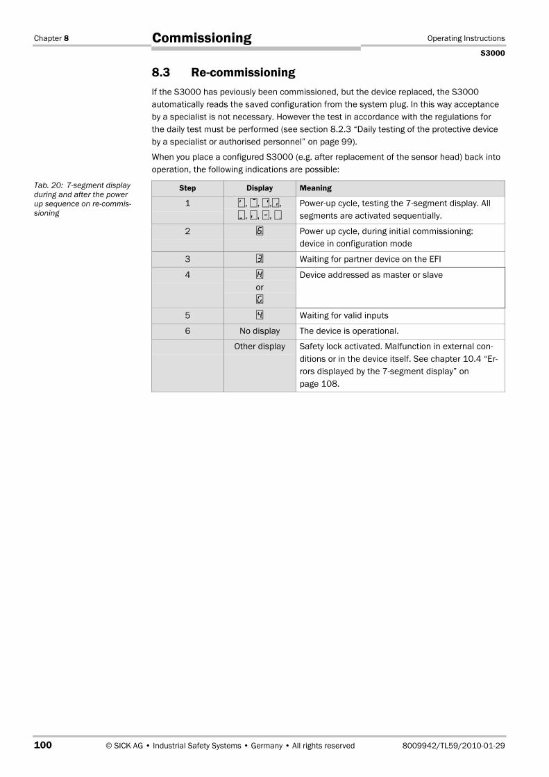
Chapter 8 Operating Instructions
S3000
100 © SICK AG • Industrial Safety Systems • Germany • All rights reserved 8009942/TL59/2010-01-29
Commissioning
8.3 Re-commissioningIf the S3000 has peviously been commissioned, but the device replaced, the S3000automatically reads the saved configuration from the system plug. In this way acceptanceby a specialist is not necessary. However the test in accordance with the regulations forthe daily test must be performed (see section 8.2.3 “Daily testing of the protective deviceby a specialist or authorised personnel” on page 99).
When you place a configured S3000 (e.g. after replacement of the sensor head) back intooperation, the following indications are possible:
Step Display Meaning
1 , , �,�, , �, �, �
Power-up cycle, testing the 7segment display. Allsegments are activated sequentially.
2 � Power up cycle, during initial commissioning:device in configuration mode
3 � Waiting for partner device on the EFI
4 �
or�
Device addressed as master or slave
5 � Waiting for valid inputs
6 No display The device is operational.
Other display Safety lock activated. Malfunction in external con-ditions or in the device itself. See chapter 10.4 “Er-rors displayed by the 7segment display” onpage 108.
Tab. 20: 7segment displayduring and after the powerup sequence on recommis-sioning
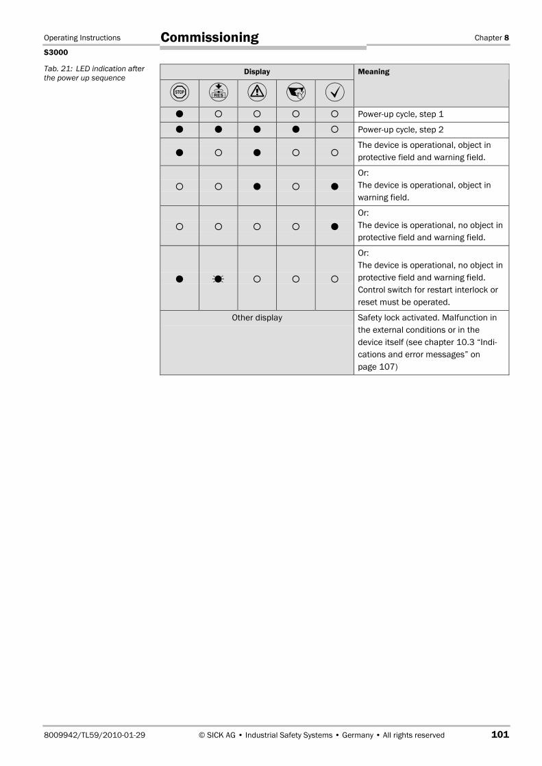
Operating Instructions Chapter 8
S3000
8009942/TL59/2010-01-29 © SICK AG • Industrial Safety Systems • Germany • All rights reserved 101
Commissioning
Display
� � � � �Meaning
� � � � � Power-up cycle, step 1
� � � � � Power-up cycle, step 2
� � � � �The device is operational, object inprotective field and warning field.
� � � � �
Or:The device is operational, object inwarning field.
� � � � �
Or:The device is operational, no object inprotective field and warning field.
� � � � �
Or:The device is operational, no object inprotective field and warning field.Control switch for restart interlock orreset must be operated.
Other display Safety lock activated. Malfunction inthe external conditions or in thedevice itself (see chapter 10.3 “Indi-cations and error messages” onpage 107)
Tab. 21: LED indication afterthe power up sequence

Chapter 9 Operating Instructions
S3000
102 © SICK AG • Industrial Safety Systems • Germany • All rights reserved 8009942/TL59/2010-01-29
Care and maintenance
9 Care and maintenance
Do not make any repairs to the device!
The S3000 does not contain any repairable components. For this reason do not open theS3000 components and only replace the parts that are described in the following chaptersas replaceable.
Switch the entire machine/system off line!
The machine/system could inadvertently start up while you are changing the front screen.As a matter of principle, always isolate the machine from the power supply during all workon the machine and safety laser scanner.
9.1 Cleaning the front screenThe safety laser scanner S3000 is largely maintenance-free. The front screen on the safetylaser scanner should however be regularly cleaned and also if contaminated.
Do not use aggressive detergents.
Do not use abrasive cleaning agents.
Static charges cause dust particles to be attracted to the front screen. You can diminishthis effect by using the anti-static plastic cleaner (SICK Part No. 5600006) and theSICK lens cloth (Part No. 4003353) (see section 12.3 “Accessories/spare parts” onpage 133).
Cleaning the front screen:
Use a clean and soft brush to remove dust from the front screen.
Now wipe the front screen with a clean and damp cloth.
9.2 Replacing the front screen
Always perform a front screen calibration after the replacement of the front screen!
After the replacement of the front screen with a new front screen you must perform a frontscreen calibration with the aid of the CDS. In this way the new front screen on the S3000is measured and the device made functional. Perform the front screen calibration at roomtemperature.
If the front screen is scratched or damaged, you must replace it. Order the replacementfront screen from SICK (see section 12.3 “Accessories/spare parts” on page 133).
• The front screen on the S3000 is an optical part that must not be contaminated orscratched.
• The front screen is only allowed to be replaced by specialist personnel in a dust- and dirt-free environment.
• Never replace the front screen during operation as dust particles could enter the device.
• It is imperative that you avoid contamination of the inside of the front screen, e.g. withfingerprints.
WARNING
Note
WARNING
Notes

Operating Instructions Chapter 9
S3000
8009942/TL59/2010-01-29 © SICK AG • Industrial Safety Systems • Germany • All rights reserved 103
Care and maintenance
• Do not use any additional sealant for sealing the front screen, e.g. silicon, as the vapoursproduced may damage the optics.
• Mount the front screen as per the following instructions to ensure that the housing issealed to IP 65.
Replacement of the front screen:
Disconnect the system plug and remove the S3000.
Take the S3000 to a clean place (office, repair shop or similar).
First clean the outside of the S3000. This prevents foreign bodies entering the devicewhen it is opened.
Undo the fixing screws � to � for the front screen.
Now remove the old front screen and the old rubber seal.
Remove any dirt from the seal groove and the mating face on the sensor head. For thispurpose if possible use a plastic cleaner that does not leave residues (see section 12.3“Accessories/spare parts” on page 133).
If necessary smear a thin coating of vaseline in the seal groove. This makes mountingeasier.
Insert the new seal � — starting in the middle —. During this process first align thecentre markings on the sensor head (� and �) and seal (� and �).
Fig. 83: Removing the fixingscrews for the front screen
Recommendation
Fig. 84: Inserting the rubberseal
�
�
�
�
�
��
�
�
�
�
�
�

Chapter 9 Operating Instructions
S3000
104 © SICK AG • Industrial Safety Systems • Germany • All rights reserved 8009942/TL59/2010-01-29
Care and maintenance
If the front seal is not inserted correctly, the front screen may be damaged. Do not use anypointed or sharp tools.
First place the seal only lightly in the rounded sections of the seal groove. In this way youwill avoid stretching the seal.
Only then press the seal home. The seal should not be stretched on insertion.
The seal is pressed in far enough when the edge of the seal and the sensor head are flush.
It is imperative that you check that the seal is seated evenly all the way around thegroove.
Check whether the mirror on the motor is clean and remove any contamination with anoptic brush.
Set a torque wrench to 0.7 Nm (hand-tight) and have this at hand.
Take the new front screen from the packaging.
Remove any remnants of packaging.
Place the front screen on the rubber seal and insert the new fixing screws � to � withspacers (see Fig. 84).
Press the front screen on the front of the cover. During this process tighten the frontscrews � to � to the torque set.
Then insert the rest of the screws � to � with spacers (see Fig. 84), and tighten usingthe torque wrench.
Re-commissioning the S3000:
Re-mount the S3000 correctly (see chapter 4 “Installation and mounting” on page 47).
Connect the S3000 system plug.After power up the S3000 automatically reads the saved configuration from the systemplug (see chapter 8.3 “Re-commissioning” on page 100).
Always perform a front screen calibration with the aid of the CDS after the replacementof the front screen!
The level of contamination is measured continuously during the operation of the S3000.For this purpose the front screen calibration must first be performed; this then serves as areference for the contamination measurement (status = not contaminated).
The front screen calibration may only be performed immediately after the replacement ofthe front screen!
The new front screen must be free of contamination at the time of the front screen calibra-tion. The front screen calibration should be performed at room temperature (10-30 °C)!
Note
Fig. 85: Depth for pressing inthe seal
WARNING
Seal edge flush withhousing edge
Seal
Housing
Operating Instructions Chapter 9
S3000
8009942/TL59/2010-01-29 © SICK AG • Industrial Safety Systems • Germany • All rights reserved 105
Care and maintenance
9.3 Replacing the I/O module
Switch the entire machine/system off line!
While you are replacing the I/0 module, the plant may start inadvertently.
As a matter of principle, always isolate the machine from the power supply during allwork on the machine and safety laser scanner.
When the I/O module is dismantled, advanced electronic components are accessible.Protect these from electrostatic discharge, contamination and moisture.
If possible use anti-static floor mats and workbench covers.
When working on the S3000, touch a bare metal surface from time to time to dischargestatic charging of your body.
Only remove the components for the S3000 from their anti-static packing immediatelyprior to installation.
Note that no liability can be accepted for damage caused by electrostatic discharge.
• The I/O module is only allowed to be replaced by specialist personnel in a clean environ-ment.
• Mount the I/O module as per the following instructions to ensure that the housing issealed to IP 65.
Replacing the I/O module:
Disconnect the system plug and remove the S3000.
Take the S3000 to a clean place (office, repair shop or similar).
First clean the outside of the S3000.This prevents foreign bodies entering the device when it is opened.
Undo the fixing screws for the I/O module.
Take hold of the I/O module with one hand at the recess for the connector to the systemplug.
With the other hand take hold of the I/O module at the dismantling aid on the undersideof the device.
Pull out the I/O module parallel to the mounting shaft.
Remove any contamination from the sealing surface and the mating surface for thesensor head. For this purpose if possible use a plastic cleaner that does not leaveresidues (see section 12.3 “Accessories/spare parts” on page 133).
Remove the I/O module from the packaging, ensure that you take adequate ESDprotection measures during this process.
Check the surfaces for cleanliness and the seal for correct seating.
Insert the I/O module in the mounting shaft parallel to the rear of the sensor head.During this process use the three surrounding sides of the shaft for orientation.
Guide the I/O module along these surfaces to the connector. During this process slidethe I/O module parallel to the rear of the sensor, avoid tilting. The I/O module can beconnected without the need to apply force.
When the I/O module is flat against the rear of the sensor head (distance approx.1 mm), tighten the screws in stages, diagonally, to 10 to 12 Nm.
WARNING
Note
Notes

Chapter 9 Operating Instructions
S3000
106 © SICK AG • Industrial Safety Systems • Germany • All rights reserved 8009942/TL59/2010-01-29
Care and maintenance
Re-commissioning the S3000:
Correctly re-mount the S3000 (see chapter 4 “Installation and mounting” on page 47).
Connect the S3000 system plug.– If you have replaced the I/O module for the same I/O module variant, after power up
the S3000 automatically reads the saved configuration from the system plug (seechapter 8.3 “Re-commissioning” on page 100).
– If you have replaced the I/O module with a different I/O module variant (e.g. Standardwith Advanced), you must perform initial commissioning (see chapter 8.1 “Initial com-missioning” on page 97).

Operating Instructions Chapter 10
S3000
8009942/TL59/2010-01-29 © SICK AG • Industrial Safety Systems • Germany • All rights reserved 107
Diagnostics
10 DiagnosticsThis chapter describes how to identify and remedy errors and malfunctions during theoperation of the safety laser scanner.
10.1 In the event of faults or errors
Cease operation if the cause of the malfunction has not been clearly identified!
Stop the machine, the system or the vehicle if you cannot clearly identify or allocate theerror and if you cannot safely remedy the malfunction.
10.2 SICK SupportIf you cannot remedy an error with the help of the information provided in this chapter,please contact your local SICK representative.
Make a note of the telephone number of your SICK subsidiary so that you or other usershave this number easily at hand. You will find the telephone number on the rear of theseoperating instructions.
Telephone number of your SICK subsidiary
10.3 Indications and error messagesThis section describes the meaning of the indications and error messages and how youcan respond. You will find a description of the indicators in section 3.8 “Indicators andoutputs” on page 45, the connections for the outputs in section 5.1 “System connection”on page 75.
Display Output level Possible cause
�� At the OSSDs Object in the protectivefield, OSSDsdeactivated
�� At the OSSDs Protective fieldunoccupied,OSSDs activated
�� At the warning fieldoutput
Object in warning field
WARNING
Tab. 22: Operational statusindicators during operation
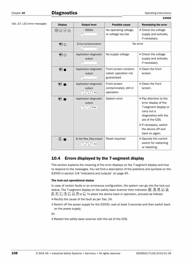
Chapter 10 Operating Instructions
S3000
108 © SICK AG • Industrial Safety Systems • Germany • All rights reserved 8009942/TL59/2010-01-29
Diagnostics
Display Output level Possible cause Remedying the error
���� OSSDs No operating voltage,or voltage too low
Check the voltagesupply and activate,if necessary.
�� Error/contamination No error
�� Application diagnosticoutput
No supply voltage Check the voltagesupply and activate,if necessary.
�� Application diagnosticoutput
Front screen contami-nated, operation notguaranteed
Clean the frontscreen.
�� Application diagnosticoutput
1 Hz
Front screencontaminated, still inoperation
Clean the frontscreen.
�� Application diagnosticoutput
4 Hz
System error Pay attention to theerror display of the7segment display orcarry out adiagnostics with theaid of the CDS.
If necessary, switchthe device off andback on again.
�� At the Res_Req output
1 Hz
Reset required Operate the controlswitch for restartingor resetting.
10.4 Errors displayed by the 7segment displayThis section explains the meaning of the error displays on the 7segment display and howto respond to the messages. You will find a description of the positions and symbols on theS3000 in section 3.8 “Indicators and outputs” on page 45.
The lockout operational status
In case of certain faults or an erroneous configuration, the system can go into the lockoutstatus. The 7segment display on the safety laser scanner then indicates �, �, �, �, �,�, �, �, �, �, �, � or �. To place the device back in operation, proceed as follows:
Rectify the cause of the fault as per Tab. 24.
Switch off the power supply for the S3000, wait at least 3 seconds and then switch backon the power supply.
Or:
Restart the safety laser scanner with the aid of the CDS.
Tab. 23: LED error messages
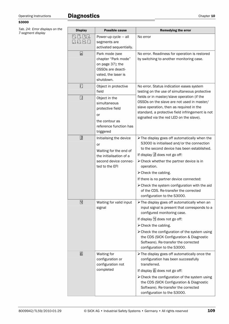
Operating Instructions Chapter 10
S3000
8009942/TL59/2010-01-29 © SICK AG • Industrial Safety Systems • Germany • All rights reserved 109
Diagnostics
Display Possible cause Remedying the error
, , �,�, , �, �, �
Power-up cycle — allsegments areactivated sequentially.
No error
� Park mode (seechapter “Park mode”on page 37); theOSSDs are deacti-vated, the laser isshutdown.
No error. Readiness for operation is restoredby switching to another monitoring case.
� Object in protectivefield
� Object in thesimultaneousprotective field
or
the contour asreference function hastriggered
No error. Status indication eases systemtesting on the use of simultaneous protectivefields or in master/slave operation (if theOSSDs on the slave are not used in master/slave operation, then as required in thestandard, a protective field infringement is notsignalled via the red LED on the slave).
� Initialising the device
or
Waiting for the end ofthe initialisation of asecond device connec-ted to the EFI
The display goes off automatically when theS3000 is initialised and/or the connectionto the second device has been established.
If display � does not go off:
Check whether the partner device is inoperation.
Check the cabling.
If there is no partner device connected:
Check the system configuration with the aidof the CDS. Re-transfer the correctedconfiguration to the S3000.
� Waiting for valid inputsignal
The display goes off automatically when aninput signal is present that corresponds to aconfigured monitoring case.
If display � does not go off:
Check the cabling.
Check the configuration of the system usingthe CDS (SICK Configuration & DiagnosticSoftware). Re-transfer the correctedconfiguration to the S3000.
� Waiting forconfiguration orconfiguration notcompleted
The display goes off automatically once theconfiguration has been successfullytransferred.
If display � does not go off:
Check the configuration of the system usingthe CDS (SICK Configuration & DiagnosticSoftware). Re-transfer the correctedconfiguration to the S3000.
Tab. 24: Error displays on the7segment display
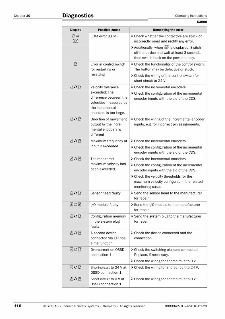
Chapter 10 Operating Instructions
S3000
110 © SICK AG • Industrial Safety Systems • Germany • All rights reserved 8009942/TL59/2010-01-29
Diagnostics
Display Possible cause Remedying the error
� or�
EDM error (EDM) Check whether the contactors are stuck orincorrectly wired and rectify any error.
Additionally, when � is displayed: Switchoff the device and wait at least 3 seconds,then switch back on the power supply.
� Error in control switchfor restarting orresetting
Check the functionality of the control switch.The button may be defective or stuck.
Check the wiring of the control switch forshort-circuit to 24 V.
� � � Velocity toleranceexceeded: Thedifference between thevelocities measured bythe incrementalencoders is too large.
Check the incremental encoders.
Check the configuration of the incrementalencoder inputs with the aid of the CDS.
� � � Direction of movementoutput by the incre-mental encoders isdifferent
Check the wiring of the incremental encoderinputs, e.g. for incorrect pin assignments.
� � � Maximum frequency atinput C exceeded
Check the incremental encoders.
Check the configuration of the incrementalencoder inputs with the aid of the CDS.
� � � The monitoredmaximum velocity hasbeen exceeded.
Check the incremental encoders.
Check the configuration of the incrementalencoder inputs with the aid of the CDS.
Check the velocity thresholds for themaximum velocity configured in the relatedmonitoring cases
� � � Sensor head faulty Send the sensor head to the manufacturerfor repair.
� � � I/O module faulty Send the I/O module to the manufacturerfor repair.
� � � Configuration memoryin the system plugfaulty
Send the system plug to the manufacturerfor repair.
� � � A second deviceconnected via EFI hasa malfunction.
Check the device connected and theconnection.
� � � Overcurrent on OSSDconnection 1
Check the switching element connected.Replace, if necessary.
Check the wiring for short-circuit to 0 V.
� � � Short-circuit to 24 V atOSSD connection 1
Check the wiring for short-circuit to 24 V.
� � � Short-circuit to 0 V atOSSD connection 1
Check the wiring for short-circuit to 0 V.

Operating Instructions Chapter 10
S3000
8009942/TL59/2010-01-29 © SICK AG • Industrial Safety Systems • Germany • All rights reserved 111
Diagnostics
Display Possible cause Remedying the error
� � � Overcurrent on OSSDconnection 2
Check the switching element connected.Replace, if necessary.
Check the wiring for short-circuit to 0 V.
� � Short-circuit to 24 V atOSSD connection 2
Check the wiring for short-circuit to 24 V.
� � � Short-circuit to 0 V atOSSD connection 2
Check the wiring for short-circuit to 0 V.
� � ! Short-circuit betweenOSSD connection 1and 2
Check the wiring and rectify the error.
� � � General OSSD wiringerror
Check the complete wiring of the OSSDs.
� Device is addressed asslave
No error. The symbol is displayed for approx.2 seconds on switching on a device that isaddressed as a slave.
� Device is addressed asmaster
No error. The symbol is displayed for approx.2 seconds on switching on a device that isaddressed as a master.
� � � The S3000 is receivingno measured valueswithin a range of atleast 90° (measuringrange maximum49 m), it thus is notdetecting anyobstacles such as e.g.building walls.
For the correct function of the safety laserscanner, always ensure that measuredvalues are received within a range of 90°;this range can be moved as required withinthe scan range.
� � � Device is dazzled Check whether the S3000 is being dazzledby an external light source, e.g. headlight,infrared light sources, stroboscopic light,sun etc.
If necessary, re-mount the device.
� � � Temperature error. Theoperating temperatureof the S3000 hasexceeded thepermissible range.
Check whether the S3000 is operated asper the permissible ambient conditions.
� � � Invalid configuration ofthe EDM
Verify that the machine-side EDM isconnected correctly.
� � � A device connected viaEFI is faulty or the con-nection has amalfunction.
Check the device connected and theconnection to this device.

Chapter 10 Operating Instructions
S3000
112 © SICK AG • Industrial Safety Systems • Germany • All rights reserved 8009942/TL59/2010-01-29
Diagnostics
Display Possible cause Remedying the error
� � � There is a short-circuitbetween the resetinput and anotherinput or output, or thereset pulse does notcomply with therequirements.
Check the cabling for cross-circuits.
Or:
Check whether the reset pulse complies withthe requirements (see Fig. 87 on page 115).
� � � Input signal for anundefined monitoringcase
� � � Incorrect sequence onswitching themonitoring cases
Check the path of the vehicle.
Or:
Check the work process on the machine orplant monitored.
If necessary, check the configuration of themonitoring cases with the aid of the CDS.
� � � Incorrect operation ofthe control inputs
Check the operation of the digital controlinputs.
� A device connected viaEFI reports amalfunction.
Carry out a fault diagnosis of the deviceconnected with the S3000.
� � � … � Channel 1 to 6 of thecontaminationmeasurement soiled
Clean the front screen.
� � ! No front screen fittedor dazzling of thecontaminationmeasurement
Re-fit the new front screen (then performfront screen calibration).
If at the time of the error a front screen wasfitted:
Check whether the S3000 is being dazzledby an external light source, e.g. headlight,infrared light source, stroboscopic light, sunetc.
� � �
�� �
Traceability dataincorrect or frontscreen calibrationfailed
Carry out a front screen calibration orreplace the S3000, if necessary.
" � � Internal error Replace the S3000.
" � � I/O module/sensorhead devicecombination invalid
Check whether the correct I/O module hasbeen used, and replace if necessary.
If you have problems during troubleshooting, contact SICK support. Keep a copy of theprint out of the results of the diagnostics at hand.
Note

Operating Instructions Chapter 10
S3000
8009942/TL59/2010-01-29 © SICK AG • Industrial Safety Systems • Germany • All rights reserved 113
Diagnostics
10.5 Extended diagnosticsThe CDS software supplied with the device (SICK Configuration & Diagnostic Software)includes extended diagnostic options. It allows you to narrow down the problem if the erroris non-specific or if you experience usage downtime problems. Detailed information to befound …
• in the online help function of the CDS (SICK Configuration & Diagnostic Software).
• in the user manual for the CDS.
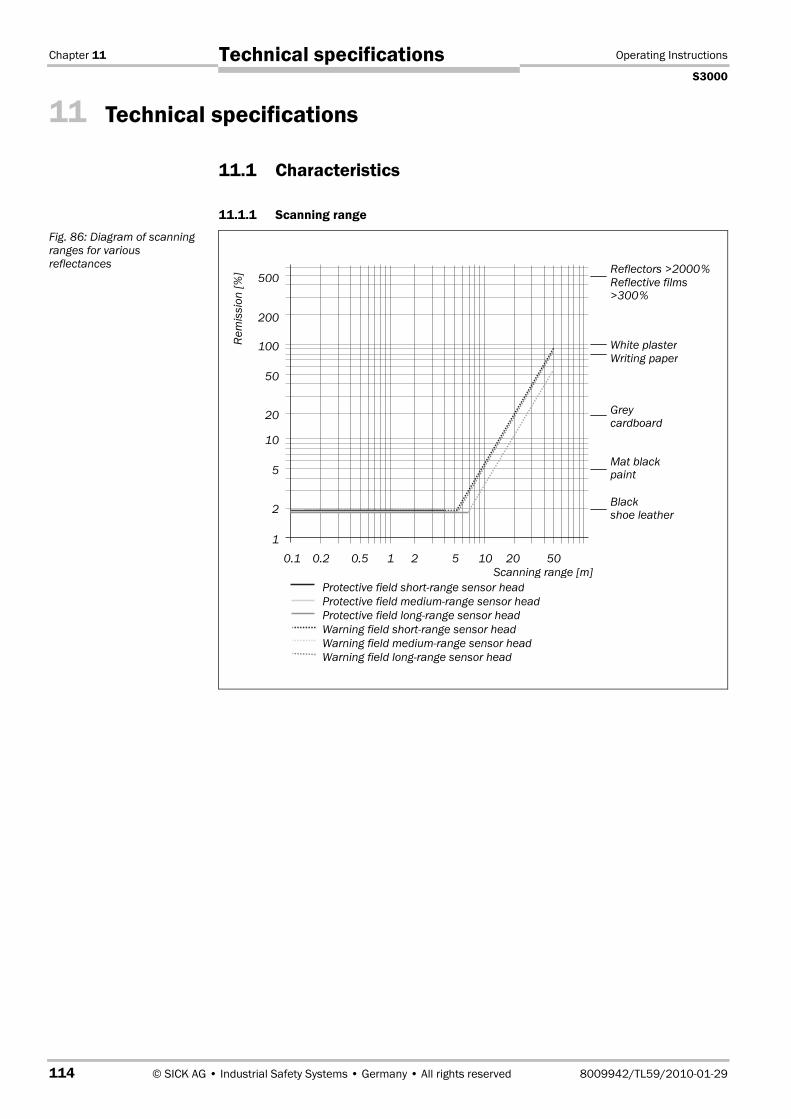
Chapter 11 Operating Instructions
S3000
114 © SICK AG • Industrial Safety Systems • Germany • All rights reserved 8009942/TL59/2010-01-29
Technical specifications
11 Technical specifications
11.1 Characteristics
11.1.1 Scanning range
Fig. 86: Diagram of scanningranges for variousreflectances
White plasterRem
issi
on[%
]
Scanning range [m]
Blackshoe leather
0.11
2
10
0.2 0.5 1 2 5 10 20 50
5
20
50
100
200
500
Mat blackpaint
Greycardboard
Writing paper
Reflectors >2000%Reflective films>300�%
Protective field short-range sensor headProtective field medium-range sensor headProtective field long-range sensor headWarning field short-range sensor headWarning field medium-range sensor headWarning field long-range sensor head

Operating Instructions Chapter 11
S3000
8009942/TL59/2010-01-29 © SICK AG • Industrial Safety Systems • Germany • All rights reserved 115
Technical specifications
11.1.2 Reset pulse
If the reset pulse on the “Reset” input is, e.g., provided by an (F)PLC, then the pulse mustbe of a specific length.
Ensure that pulses do not have a frequency of 1 Hz or 4 Hz, as otherwise there may beoverlaps with the application diagnostic output signals for “Front screen contamination” or“System error”. This overlap will result in an error on the safety laser scanner.
11.2 OSSD response times
The total response time of your application is dependent on …
• the basic response time at the related resolution and the maximum protective fieldrange.
• the multiple sampling used.
• the OSSDs used.
Calculation of the total response time TS:
TS = tB + TMFA + TEFI
Where …
tB = Basic response time (60 ms or 120 ms)
TMFA = Supplement due to multiple sampling > 2
TEFI = Supplement for the usage of external OSSDs via EFI
Fig. 87: Reset pulserequirements
t [ms]
500250
500 ms
10
1000 1500 1750 2000
20
–20
–10
V [S]
0

Chapter 11 Operating Instructions
S3000
116 © SICK AG • Industrial Safety Systems • Germany • All rights reserved 8009942/TL59/2010-01-29
Technical specifications
Multiple sampling
The S3000 is always set to a minimum of 2 times multiple sampling.. From a multiplesampling of 3 you must add a supplement to the response time. The related supplement isdependent on the basic response time and the multiple sampling.
Multiple sampling Supplement for basicresponse time 60 ms
Supplement for basicresponse time 120 ms
3 times 30 ms 60 ms
4 times 60 ms 120 ms
5 times 90 ms 180 ms
6 times 120 ms 240 ms
7 times 150 ms 300 ms
8 times 180 ms 360 ms
9 times 210 ms 420 ms
10 times 240 ms 480 ms
11 times 270 ms 540 ms
12 times 300 ms 600 ms
13 times 330 ms 660 ms
14 times 360 ms 720 ms
15 times 390 ms 780 ms
16 times 420 ms 840 ms
External OSSDs
If you use the OSSDs on another device via the EFI as external switching outputs (forexample with two S3000 connected together), the response time increases by 20 ms ineach case.
Tab. 25: Supplements formultiple sampling
Note
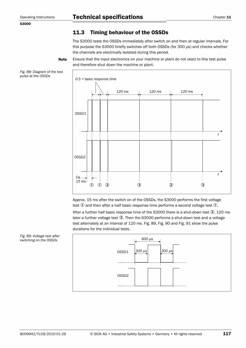
Operating Instructions Chapter 11
S3000
8009942/TL59/2010-01-29 © SICK AG • Industrial Safety Systems • Germany • All rights reserved 117
Technical specifications
11.3 Timing behaviour of the OSSDsThe S3000 tests the OSSDs immediately after switch on and then at regular intervals. Forthis purpose the S3000 briefly switches off both OSSDs (for 300 µs) and checks whetherthe channels are electrically isolated during this period.
Ensure that the input electronics on your machine or plant do not react to this test pulseand therefore shut down the machine or plant.
Approx. 15 ms after the switch on of the OSSDs, the S3000 performs the first voltagetest � and then after a half basic response time performs a second voltage test �.
After a further half basic response time of the S3000 there is a shut-down test �, 120 mslater a further voltage test �. Then the S3000 performs a shut-down test and a voltagetest alternately at an interval of 120 ms. Fig. 89, Fig. 90 and Fig. 91 show the pulsedurations for the individual tests.
Note
Fig. 88: Diagram of the testpulse at the OSSDs
Fig. 89: Voltage test afterswitching on the OSSDs 600 µs
300 µs300 µsOSSD1
OSSD2
0.5 × basic response time
120 ms 120 ms 120 ms
Ca.15 ms
� � �� ��
OSSD1
OSSD2
t
t

Chapter 11 Operating Instructions
S3000
118 © SICK AG • Industrial Safety Systems • Germany • All rights reserved 8009942/TL59/2010-01-29
Technical specifications
Fig. 90: Shut-down test
Fig. 91: Voltage test
600 µs
300 µs
300 µsOSSD1
OSSD2
300 µsOSSD1
OSSD2

Operating Instructions Chapter 11
S3000
8009942/TL59/2010-01-29 © SICK AG • Industrial Safety Systems • Germany • All rights reserved 119
Technical specifications
11.4 Data sheet
Minimum Typical Maximum
General dataLaser protection class Laser class 1
(according to IEC 60�825-1 as well asCDRH 21 CFR 1040.10 and 1040.11;excluded are deviations due to LaserNotice No. 50, dated 24.06.2007)
Enclosure rating IP 65 (EN 60�529)Protection class II (EN 50�178)9)
Type Type 3 (EN 61�4961)Safety integrity level10) SIL2 (IEC 61�508)
SILCL2 (EN 62�061)Category Category 3 (EN ISO 13�8491)Performance Level PL d11) (EN ISO 13�849)PFHd (mean probability of a dangerous failureper hour)
76,7 × 10⁻⁹
TM (mission time) 20 years (EN ISO 13�849)Operating temperature range –10 °C +50 °CStorage temperature range –25 °C +70 °C
max. 24 hHumidity (taking into account the operatingtemperature range)
EN 61�4961, section 5.1.2 and 5.4.2,as well as CLC/TS 61�4963, section5.4.2
Vibration EN 61�4961, section 5.1.2 and 5.4.4.1,as well as CLC/TS 61�4963, section5.4.4.2
Frequency range 10 Hz 150 HzAmplitude 0.35 mm or 5 g
Shock resistanceSingle shock 15 g, 11 ms (EN 60�068227)Continuous shock 10 g, 16 ms (EN 61�4961, section
5.1.2 and 5.4.4.2, as well asCLC/TS 61�4963, section 5.4.4.2)
9) Safety extra-low voltage SELV/PELV.10) For detailed information on the exact design of your machine/system, please contact your local SICK
representative.11) PL e can be achieved using additional devices, e.g. by using special actuators and a safety controller
Flexi Soft. However, an exact analysis of the performance levels by a safety specialist with the aid of theSISTEMA software is always necessary.
Tab. 26: Data sheet S3000

Chapter 11 Operating Instructions
S3000
120 © SICK AG • Industrial Safety Systems • Germany • All rights reserved 8009942/TL59/2010-01-29
Technical specifications
Minimum Typical Maximum
Sender Pulsed laser diodeWavelength 880 nm 905 nm 935 nmDivergence of the collimated beam 2.5 mradPulse duration 3.1 nsAverage output power 562 µWSize of light spot at the front screen 12 mmSize of light spot at 4,0 m scanning range 23 mmSize of light spot at 5.5 m scanning range 27 mmSize of light spot at 7.0 m scanning range 32 mm
HousingMaterial Aluminium die-castColour RAL 1021 (rape yellow)
Front screenMaterial PolycarbonateSurface finish Outside with scratch-resistant coating
System plug ESD protectedDimensions S300012)
Height 185 mmWidth 155 mmDepth 160 mm
Total weight 3.3 kg
Functional dataProtective field of the sensor head with 4.0 mscanning range13) at 120 ms response time
At 30 mm resolutionw 2.80 mAt 40 mm resolution 3.80 mAt 50 mm resolution 4.00 mAt 70 mm resolution 4.00 mAt 150 mm resolution 4.00 m
Protective field of the sensor head with 4,0 mscanning range at 60 ms response time
At 30 mm resolution 1.90 mAt 40 mm resolution 2.60 mAt 50 mm resolution 3.30 mAt 70 mm resolution 4.00 mAt 150 mm resolution 4.00 m
Protective field of the sensor head with 5.5 mscanning range at 120 ms response time
At 30 mm resolution 2.80 mAt 40 mm resolution 3.80 mAt 50 mm resolution 4.80 mAt 70 mm resolution 5.50 mAt 150 mm resolution 5.50 m
12) Without projection of cable glands with system plug mounted.13) Radial distance to the safety laser scanner.

Operating Instructions Chapter 11
S3000
8009942/TL59/2010-01-29 © SICK AG • Industrial Safety Systems • Germany • All rights reserved 121
Technical specifications
Minimum Typical Maximum
Protective field of the sensor head with 5.5 mscanning range at 60 ms response time
At 30 mm resolution 1.90 mAt 40 mm resolution 2.60 mAt 50 mm resolution 3.30 mAt 70 mm resolution 4.70 mAt 150 mm resolution 5.50 m
Protective field of the sensor head with 7 mscanning range at 120 ms response time
At 30 mm resolution 2.80 mAt 40 mm resolution 3.80 mAt 50 mm resolution 4.80 mAt 70 mm resolution 7.00 mAt 150 mm resolution 7.00 m
Protective field of the sensor head with 7 mscanning range at 60 ms response time
At 30 mm resolution 1.90 mAt 40 mm resolution 2.60 mAt 50 mm resolution 3.30 mAt 70 mm resolution 4.70 mAt 150 mm resolution 7.00 m
Scan angle 190°(–5° to185°)
Reflectivity 1.8�% Several1000�%(Reflectors)
Resolution 30, 40, 50, 70, 150 mmAngular resolution 0.50° 0.25°Protective field supplement generallynecessary
100 mm
Supplement for retroreflectors in scan planeat a distance of less than 1 m to the protectivefield boundary
200 mm
Measurement error for measured data outputup to 5.5 m and 1.8�% reflectivity
Systematic error ±5 mmStatistical incl. systematic errors
at 1 σ ±24 mmat 2 σ ±43 mmat 3 σ ±62 mmat 4 σ ±80 mmat 5 σ ±99 mm
Evenness of the scan field at 5.5 m ±70 mmEvenness of the scan field at 7 m ±88 mm

Chapter 11 Operating Instructions
S3000
122 © SICK AG • Industrial Safety Systems • Germany • All rights reserved 8009942/TL59/2010-01-29
Technical specifications
Minimum Typical Maximum
Distance from mirror axis of rotation (zeropoint on the X and Y axis) to the rear of thedevice
93 mm
Distance between centre of the scan planeand the bottom edge of the housing
63 mm
Warning field range (radial) Approx.20 m14)
49 m
Distance measuring range 49 mNumber of multiple samplings(configurable via CDS)
2 16
Power up time 9 s 20 sRestart after (configurable) 2 s 60 s
Electrical dataElectrical connection Plug-in connection housing with screw
terminal connectionsTechnical specifications, screw terminals
Cross-section of rigid cores 0.14 mm² 1.5 mm²Cross-section of flexible cores15) 0.14 mm² 1.0 mm²American Wire Gauge (AWG) 26 16Insulation stripping length for the cores 5 mmScrew tightening torque 0.22 Nm 0.25 Nm
Cable length for power supply tolerance ±10�%For wire cross-section 1 mm² 50 mFor wire cross-section 0.5 mm² 25 mFor wire cross-section 0.25 mm² 12 m
Cable length for power supply tolerance ±5�%For wire cross-section 1 mm² 60 mFor wire cross-section 0.5 mm² 30 mFor wire cross-section 0.25 mm² 15 m
Cable length for power supply tolerance ±1�%For wire cross-section 1 mm² 70 mFor wire cross-section 0.5 mm² 35 mFor wire cross-section 0.25 mm² 17 m
Supply voltage (SELV)The voltage supply must be capable ofbuffering brief mains voltage failures of 20 msas specified in EN 60�204. Suitable powersupplies are available as accessories fromSICK (Siemens type series 6 EP 1)
16.8 V 24 V 28.8 V
Permissible residual ripple16) ± 5%Switch on current17) 2 AOperating current at 24 V without output load 0.8 A
14) For objects with 20�% reflectivity.15) Core terminating sleeves are not required.16) The absolute voltage level must not drop below the specified minimum voltage.17) The load currents for the input capacitors are not taken into account.
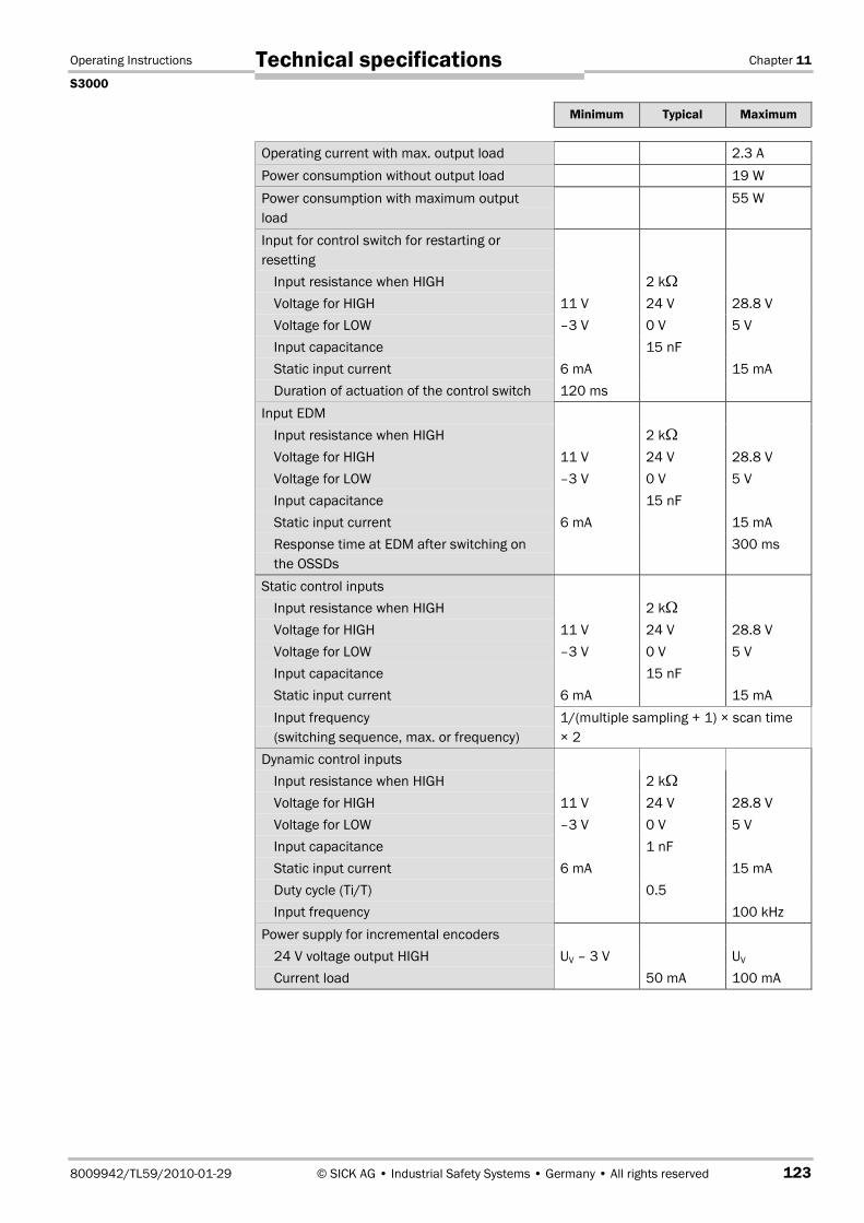
Operating Instructions Chapter 11
S3000
8009942/TL59/2010-01-29 © SICK AG • Industrial Safety Systems • Germany • All rights reserved 123
Technical specifications
Minimum Typical Maximum
Operating current with max. output load 2.3 APower consumption without output load 19 WPower consumption with maximum outputload
55 W
Input for control switch for restarting orresetting
Input resistance when HIGH 2 k�Voltage for HIGH 11 V 24 V 28.8 VVoltage for LOW –3 V 0 V 5 VInput capacitance 15 nFStatic input current 6 mA 15 mADuration of actuation of the control switch 120 ms
Input EDMInput resistance when HIGH 2 k�Voltage for HIGH 11 V 24 V 28.8 VVoltage for LOW –3 V 0 V 5 VInput capacitance 15 nFStatic input current 6 mA 15 mAResponse time at EDM after switching onthe OSSDs
300 ms
Static control inputsInput resistance when HIGH 2 k�Voltage for HIGH 11 V 24 V 28.8 VVoltage for LOW –3 V 0 V 5 VInput capacitance 15 nFStatic input current 6 mA 15 mAInput frequency(switching sequence, max. or frequency)
1/(multiple sampling + 1) × scan time× 2
Dynamic control inputsInput resistance when HIGH 2 k�Voltage for HIGH 11 V 24 V 28.8 VVoltage for LOW –3 V 0 V 5 VInput capacitance 1 nFStatic input current 6 mA 15 mADuty cycle (Ti/T) 0.5Input frequency 100 kHz
Power supply for incremental encoders24 V voltage output HIGH UV – 3 V UV
Current load 50 mA 100 mA

Chapter 11 Operating Instructions
S3000
124 © SICK AG • Industrial Safety Systems • Germany • All rights reserved 8009942/TL59/2010-01-29
Technical specifications
Minimum Typical Maximum
OSSDsOutput signal switching device pair 2 PNP semiconductors, short-circuit
protected18), cross-circuit monitoredHIGH switching voltage at 500 mA UV – 2.7 V UV
Switching voltage LOW 0 V 0 V 3.5 VSource switching current 6 mA 0.2 A 0.5 ALeakage current19) 250 µALoad inductance20) 2.2 HLoad capacity 2.2 µF at
50 �Switching sequence (without switching andwithout simultaneous monitoring)
Depending on load inductance
Permissible cable resistance21) 2.5 �Test pulse width22) 230 µs 300 µsTest frequency 120 msSwitching time of the OSSDs from red togreen
120 ms
Time offset on switching the OSSDs betweenOSSD2 and OSSD1
1.3 ms 2 ms
Application diagnostic outputs warning field,contamination of the front screen/error, resetnecessary
HIGH switching voltage at 200 mA UV – 3.3 V UV
Source switching current 100 mA 200 mACurrent limiting (after 5 ms at 25 °C) 600 mA 920 mAPower up delay 1.4 ms 2 msSwitch off delay 0.7 ms 2 ms
18) Applies to the voltage range between Uv and 0 V.19) In the case of a fault (the 0V cable is open circuit) the leakage current flows through the OSSD cable as a
maximum. The downstream controller must detect this status as LOW. An FPLC (fail-safe programmable logiccontroller) must detect this status.
20) The maximum rated load inductance is higher with lower switching sequence.
21) Make sure to limit the individual line core resistance to the downstream controller to this value to ensure thata short-circuit between the outputs is safely detected. (Also note EN 60�2041.)
22) When active, the outputs are tested cyclically (brief LOW). When selecting the downstream controllers, makesure that the test pulses do not result in deactivation.

Operating Instructions Chapter 11
S3000
8009942/TL59/2010-01-29 © SICK AG • Industrial Safety Systems • Germany • All rights reserved 125
Technical specifications
Minimum Typical Maximum
Incremental encoders that can be evaluatedType Two-channel rotary encoder with 90°
phase offsetEnclosure rating IP 54Supply voltage 24 VOutputs required on the incrementalencoders
Push/pull
Pulse frequency 100 kHzNumber of pulses per cm 50Cable length (screened) 10 m
Configuration and diagnostics interfaceCommunication protocol RS232 (proprietary)Transmission speed 9600 baud
19�200 baud38�400 baud
Cable length at 9600 baud and0.25mm² cables
15 m
Galvanic de-coupling NoOutput TxD HIGH 5 V 15 VOutput TxD LOW –15 V –5 VVoltage range RxD –15 V 15 VSwitching threshold RxD LOW –15 V 0.4 VSwitching threshold RxD HIGH 2.4 V 15 VShort-circuit current at TxD –60 mA 60 mAMax. voltage level at RxD –15 V 15 VMax. voltage level at TxD –11 V 11 V
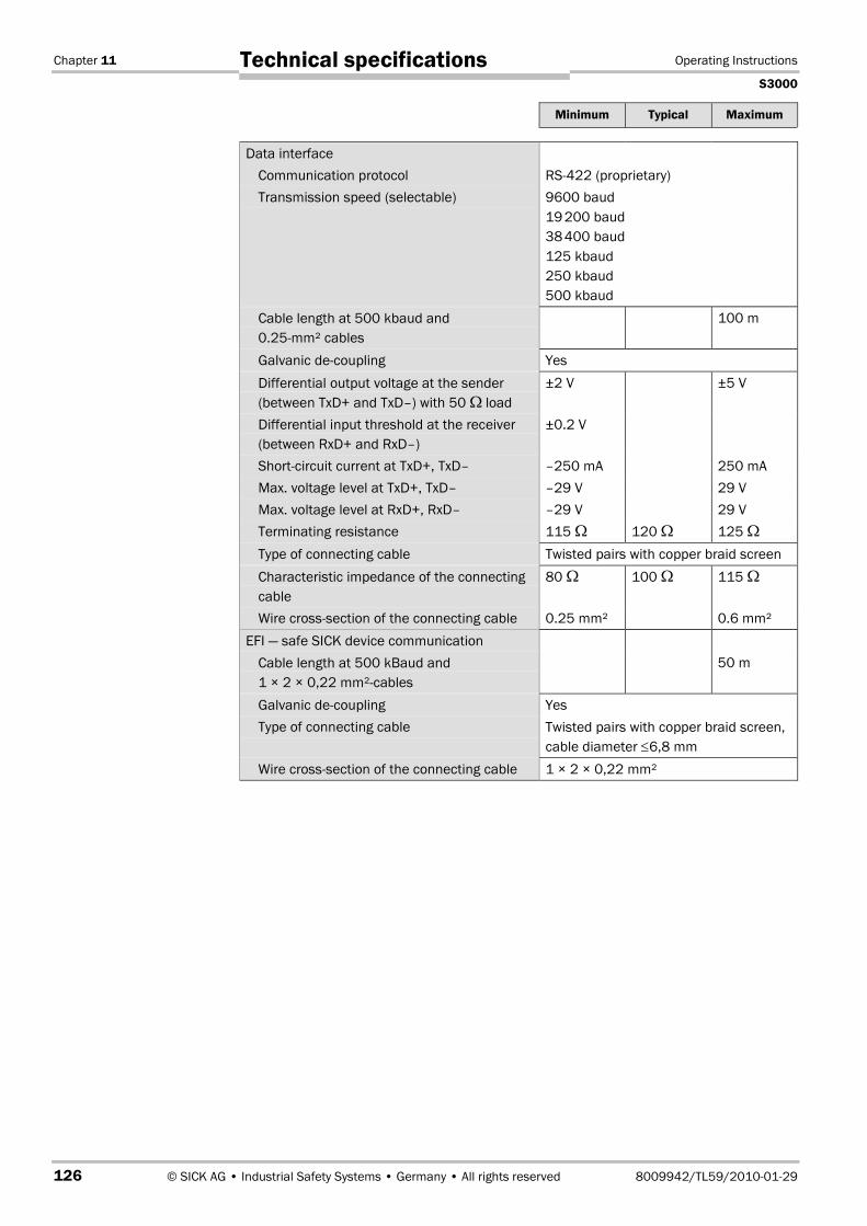
Chapter 11 Operating Instructions
S3000
126 © SICK AG • Industrial Safety Systems • Germany • All rights reserved 8009942/TL59/2010-01-29
Technical specifications
Minimum Typical Maximum
Data interfaceCommunication protocol RS422 (proprietary)Transmission speed (selectable) 9600 baud
19�200 baud38�400 baud125 kbaud250 kbaud500 kbaud
Cable length at 500 kbaud and0.25mm² cables
100 m
Galvanic de-coupling YesDifferential output voltage at the sender(between TxD+ and TxD–) with 50 � load
±2 V ±5 V
Differential input threshold at the receiver(between RxD+ and RxD–)
±0.2 V
Short-circuit current at TxD+, TxD– –250 mA 250 mAMax. voltage level at TxD+, TxD– –29 V 29 VMax. voltage level at RxD+, RxD– –29 V 29 VTerminating resistance 115 � 120 � 125 �Type of connecting cable Twisted pairs with copper braid screenCharacteristic impedance of the connectingcable
80 � 100 � 115 �
Wire cross-section of the connecting cable 0.25 mm² 0.6 mm²EFI — safe SICK device communication
Cable length at 500 kBaud and1 × 2 × 0,22 mm²cables
50 m
Galvanic de-coupling YesType of connecting cable Twisted pairs with copper braid screen,
cable diameter ≤6,8 mmWire cross-section of the connecting cable 1 × 2 × 0,22 mm²

Operating Instructions Chapter 11
S3000
8009942/TL59/2010-01-29 © SICK AG • Industrial Safety Systems • Germany • All rights reserved 127
Technical specifications
11.5 EFI status information and control commandsIf devices are connected together via EFI, EFI status information and control commandsare exchanged. Tab. 27 and Tab. 28 shows the status information that can be retrievedand the possible control commands for the S3000.
The information in square brackets reflects the names used in the CDS and in the FlexiSoft Designer.
Status information Meaning/effect
1. OSSD on [OSSD] • Logical 1, if the internal OSSD of the S3000 isswitched on (green)
• Logical 0, if the OSSD of the S3000 is switchedoff (red)
Warning field unoccupied [WF LED] • Logical 1, if the warning field for the is S3000unoccupied
Contamination [Weak] • Logical 1, on contamination of the front screenReset required [Res_Req] • Logical 1, if reset requiredReset button pressed [Res. Pressed] • Logical 1, if the reset button is pressed on the
S3000I/O error [I/O Error] • Logical 0, if there is no error on the S3000
• Logical 1, if there is an error on the S3000Control input A1 [In A1] • Logical 1, if the connection of control input A1
is HIGHNote: The control inputs on the S3000 are usedto switch the monitoring cases on the S3000.
Control input A2 [In A2] • Logical 1, if the connection of control input A2is HIGH
Control input B1 [In B1] • Logical 1, if the connection of control input B1is HIGH
Control input B2 [In B2] • Logical 1, if the connection of control input B2is HIGH
Control input C1 [In C1] • Logical 1, if the connection of control input C1is HIGH
Control input C2 [In C2] • Logical 1, if the connection of control input C2is HIGH
Control input D1 [In D1] • Logical 1, if the connection of control input D1is HIGH
Control input D2 [In D2] • Logical 1, if the connection of control input D2is HIGH
Allocated protective fieldunoccupied [PF]
• Logical 1, if the active allocated protective fieldis unoccupied
Allocated warning field unoccupied[WF]
• Logical 1, if the active allocated warning field isunoccupied
Simultaneous protective fieldunoccupied [Sim. PF]
• Logical 1, if the simultaneously monitoredprotective field is unoccupied
Simultaneous warning fieldunoccupied [Sim. WF]
• Logical 1, if the simultaneously monitoredwarning field is unoccupied
Note
Tab. 27: Status informationof the S3000 (Data from theS3000)
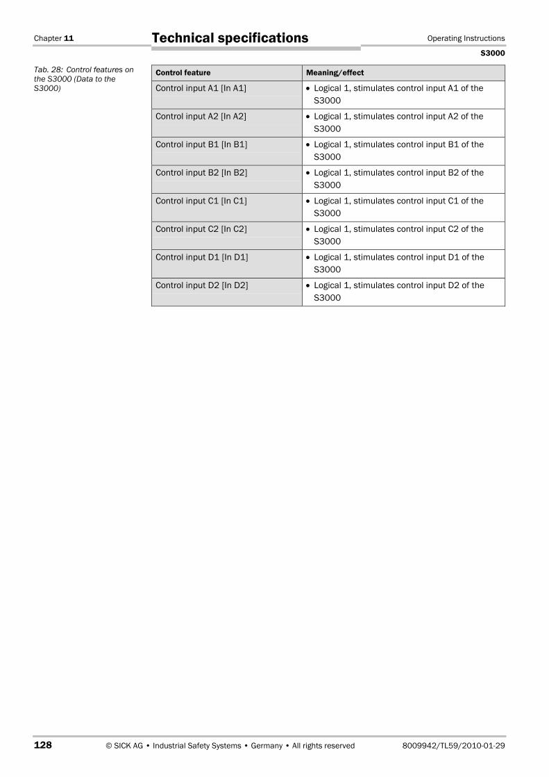
Chapter 11 Operating Instructions
S3000
128 © SICK AG • Industrial Safety Systems • Germany • All rights reserved 8009942/TL59/2010-01-29
Technical specifications
Control feature Meaning/effect
Control input A1 [In A1] • Logical 1, stimulates control input A1 of theS3000
Control input A2 [In A2] • Logical 1, stimulates control input A2 of theS3000
Control input B1 [In B1] • Logical 1, stimulates control input B1 of theS3000
Control input B2 [In B2] • Logical 1, stimulates control input B2 of theS3000
Control input C1 [In C1] • Logical 1, stimulates control input C1 of theS3000
Control input C2 [In C2] • Logical 1, stimulates control input C2 of theS3000
Control input D1 [In D1] • Logical 1, stimulates control input D1 of theS3000
Control input D2 [In D2] • Logical 1, stimulates control input D2 of theS3000
Tab. 28: Control features onthe S3000 (Data to theS3000)

Operating Instructions Chapter 11
S3000
8009942/TL59/2010-01-29 © SICK AG • Industrial Safety Systems • Germany • All rights reserved 129
Technical specifications
11.6 Dimensional drawings
11.6.1 S3000
Fig. 92: Dimensional drawingS3000 (mm)
147
136.
8
65.2
27.8
9316
0
77.5
155
92.5
13.5
23
Connector rangeapprox. 270
211185
63
120 31.755 35
211185
78.5 53.2
M8
×9
Area
tobe
kept
clea
rdu
ring
inst
alla
tion
ofth
esc
anne
r
M6 ×8 Referencepoints formounting
63
155
160
Beam diameterReceiver = 44
Beam diameterSender = 15
Axis
ofro
tatio
nof
mot
or

Chapter 11 Operating Instructions
S3000
130 © SICK AG • Industrial Safety Systems • Germany • All rights reserved 8009942/TL59/2010-01-29
Technical specifications
11.6.2 Mounting kits
Fig. 93: Dimensional drawing,mounting kit 1, 2 and 3 (mm)
Fig. 94: Dimensional drawingHeavy Duty mounting bracket
8030220
160
193.2175
120
87.522.5
67
7160
46
∅9
30
183
∅9 71106.
110
251.8
∅9
46.531.5
16.5
DIN74 Am6
9°9°
222.51
166
5°5°
144.02
5°5°
Scan plane origin
Min
.100
Max
.590
255
Min
.340
166122 Scan plane origin
4 × ∅13
Max
.350

Operating Instructions Chapter 11
S3000
8009942/TL59/2010-01-29 © SICK AG • Industrial Safety Systems • Germany • All rights reserved 131
Technical specifications
11.6.3 Scan plane origin
Fig. 95: Dimensional drawingof the scan plane (mm)
Fig. 96: Dimensional drawingof the scan plane withmounting kit 3 (mm)
102
63
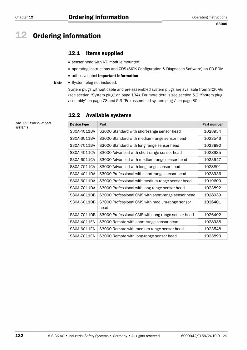
Chapter 12 Operating Instructions
S3000
132 © SICK AG • Industrial Safety Systems • Germany • All rights reserved 8009942/TL59/2010-01-29
Ordering information
12 Ordering information
12.1 Items supplied• sensor head with I/O module mounted
• operating instructions and CDS (SICK Configuration & Diagnostic Software) on CDROM
• adhesive label Important information
• System plug not included.
System plugs without cable and pre-assembled system plugs are available from SICK AG(see section “System plug” on page 134). For more details see section 5.2 “System plugassembly” on page 78 and 5.3 “Pre-assembled system plugs” on page 80.
12.2 Available systemsDevice type Part Part number
S30A-4011BA S3000 Standard with short-range sensor head 1028934
S30A-6011BA S3000 Standard with medium-range sensor head 1023546
S30A-7011BA S3000 Standard with long-range sensor head 1023890
S30A-4011CA S3000 Advanced with short-range sensor head 1028935
S30A-6011CA S3000 Advanced with medium-range sensor head 1023547
S30A-7011CA S3000 Advanced with long-range sensor head 1023891
S30A-4011DA S3000 Professional with short-range sensor head 1028936
S30A-6011DA S3000 Professional with medium-range sensor head 1019600
S30A-7011DA S3000 Professional with long-range sensor head 1023892
S30A-4011DB S3000 Professional CMS with short-range sensor head 1028939
S30A-6011DB S3000 Professional CMS with medium-range sensorhead
1026401
S30A-7011DB S3000 Professional CMS with long-range sensor head 1026402
S30A-4011EA S3000 Remote with short-range sensor head 1028938
S30A-6011EA S3000 Remote with medium-range sensor head 1023548
S30A-7011EA S3000 Remote with long-range sensor head 1023893
Note
Tab. 29: Part numberssystems

Operating Instructions Chapter 12
S3000
8009942/TL59/2010-01-29 © SICK AG • Industrial Safety Systems • Germany • All rights reserved 133
Ordering information
12.3 Accessories/spare parts
12.3.1 Sensor heads
Part Description Part number
Shortrange Sensor head with up to 4 m scanning range 2034999
Medium-range Sensor head with up to 5.5 m scanning range 2022972
Long-range Sensor head with up to 7 m scanning range 2026747
12.3.2 I/O modules
I/O module Part number
Standard 2026801
Advanced 2026802
Professional 2022827
Professional CMS 2030915
Remote 2026803
12.3.3 Mounting kits
Mounting kit Description Part number
1 Mounting bracket for direct mounting at the rearon wall or machine.
No adjustment facility
2015623
2 Bracket only in conjunction with mounting kit 1.Mounting at the rear on wall or machine.Longitudinal and cross-wise adjustment possible
2015624
3 Bracket only in conjunction with mounting kit 1and 2. Mounting at the rear or below on wall,floor or machine. Longitudinal and cross-wiseadjustment possible
2015625
Heavy Dutymounting bracket
Mounting bracket, Heavy Duty version, withprotective cover, steel, painted, for floormounting, height adjustment possible
7087514
Tab. 30: Part numberssensor heads
Tab. 31: Part numbers I/Omodules
Tab. 32: Part numbersmounting kit

Chapter 12 Operating Instructions
S3000
134 © SICK AG • Industrial Safety Systems • Germany • All rights reserved 8009942/TL59/2010-01-29
Ordering information
12.3.4 System plug
Suitable forSystem plug Description
Stan
dard
Adva
nced
Prof
essi
onal
Prof
essi
onal
CMS
Rem
ote
Part number
SX0A-A0000B Without cable, for on-site assembly, one M20cable gland and one M13 blanking plug
x x x x x 2023797
SX0A-A0000D Without cable, for on-site assembly, cableoutlet at the rear, one M20 cable gland andone M13 blanking plug
x x x x x 2023310
SX0A-B0905B Pre-assembled, 5 m cable length, 9 cores,one M20 cable gland and one M13 blankingplug
x x 2027170
SX0A-B0905G Pre-assembled, 5 m cable length, 9 cores,cable outlet at rear, one M20 cable gland andone M13 blanking plug
x x 2049222
SX0A-B0910B Pre-assembled, 10 m cable length, 9 cores,one M20 cable gland and one M13 blankingplug
x x 2027171
SX0A-B0920B Pre-assembled, 20 m cable length, 9 cores,one M20 cable gland and one M13 blankingplug
x x 2027814
SX0A-B1305B Pre-assembled, 5 m cable length, 13 cores,one M20 cable gland and one M13 blankingplug
x 2027172
SX0A-B1310B Pre-assembled, 10 m cable length, 13 cores,one M20 cable gland and one M13 blankingplug
x 2027173
SX0A-B1320B Pre-assembled, 20 m cable length, 13 cores,one M20 cable gland and one M13 blankingplug
x 2027815
SX0A-B1705B Pre-assembled, 5 m cable length, 17 cores,one M20 cable gland and one M13 blankingplug
x x 2027174
SX0A-B1710B Pre-assembled, 10 m cable length, 17 cores,one M20 cable gland and one M13 blankingplug
x x 2027175
SX0A-B1720B Pre-assembled, 20 m cable length, 17 cores,one M20 cable gland and one M13 blankingplug
x x 2027816
SX0A-B1305D Pre-assembled, 5 m cable length, 13 cores,one M20 cable gland, three M12 blankingplugs, 2 EMC-proof cable glands
x 2027176
SX0A-B1310D Pre-assembled, 10 m cable length, 13 cores,one M20 cable gland, three M12 blankingplugs, 2 EMC-proof cable glands
x 2027177
12.3.5 Service cable
Part Description Part number
Service cable 2 m Connection cable between the serial interface ofthe PC and the configuration interfaceM8�×4-pin/DSub 9-pin approx. 2 m
6021195
Service cable 10 m Connection cable between the serial interface ofthe PC and the configuration interfaceM8�×4-pin/DSub 9-pin approx. 10 m
2027649
Tab. 33: Part numberssystem plugs
Tab. 34: Part numbersservice cables
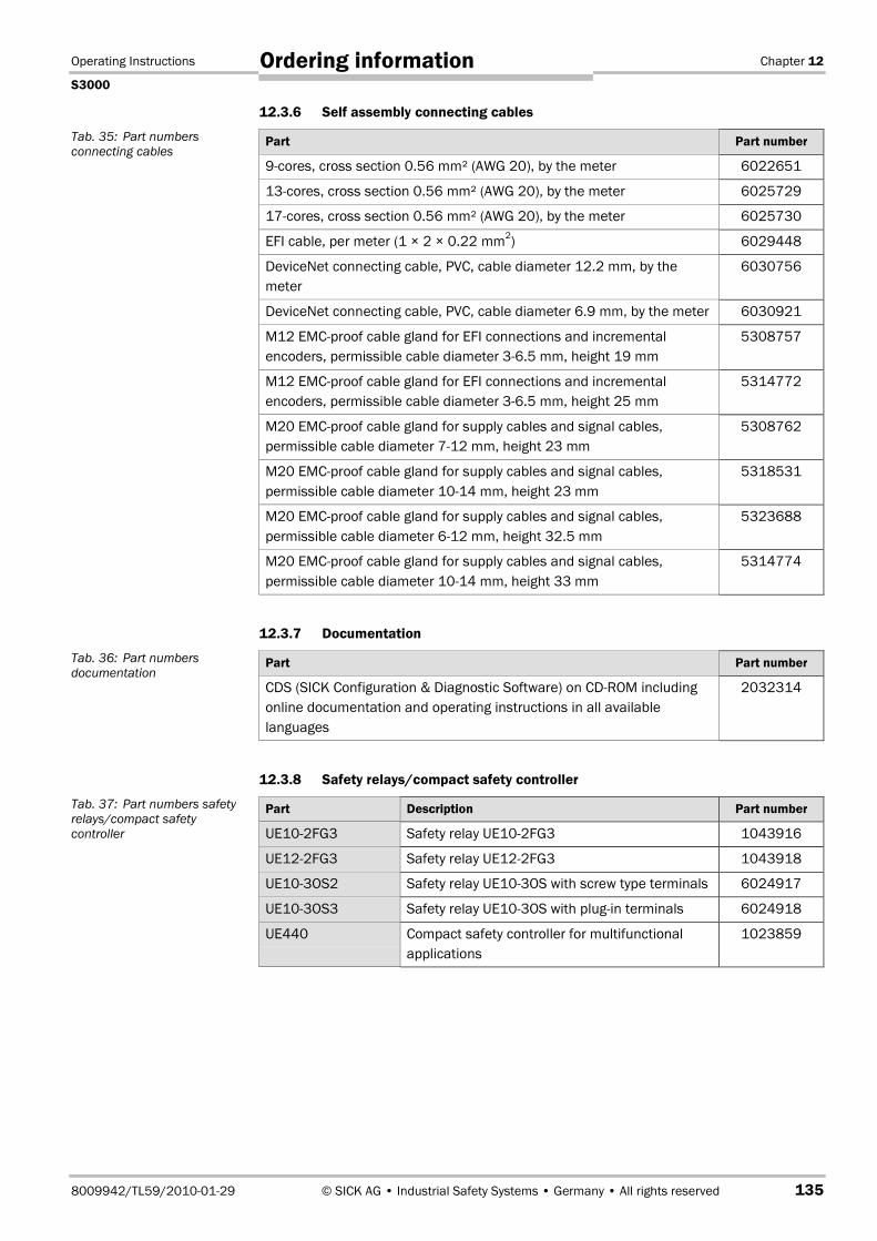
Operating Instructions Chapter 12
S3000
8009942/TL59/2010-01-29 © SICK AG • Industrial Safety Systems • Germany • All rights reserved 135
Ordering information
12.3.6 Self assembly connecting cables
Part Part number
9cores, cross section 0.56 mm² (AWG 20), by the meter 6022651
13-cores, cross section 0.56 mm² (AWG 20), by the meter 6025729
17-cores, cross section 0.56 mm² (AWG 20), by the meter 6025730
EFI cable, per meter (1 × 2 × 0.22 mm2) 6029448
DeviceNet connecting cable, PVC, cable diameter 12.2 mm, by themeter
6030756
DeviceNet connecting cable, PVC, cable diameter 6.9 mm, by the meter 6030921
M12 EMC-proof cable gland for EFI connections and incrementalencoders, permissible cable diameter 3-6.5 mm, height 19 mm
5308757
M12 EMC-proof cable gland for EFI connections and incrementalencoders, permissible cable diameter 3-6.5 mm, height 25 mm
5314772
M20 EMC-proof cable gland for supply cables and signal cables,permissible cable diameter 7-12 mm, height 23 mm
5308762
M20 EMC-proof cable gland for supply cables and signal cables,permissible cable diameter 10-14 mm, height 23 mm
5318531
M20 EMC-proof cable gland for supply cables and signal cables,permissible cable diameter 6-12 mm, height 32.5 mm
5323688
M20 EMC-proof cable gland for supply cables and signal cables,permissible cable diameter 10-14 mm, height 33 mm
5314774
12.3.7 Documentation
Part Part number
CDS (SICK Configuration & Diagnostic Software) on CDROM includingonline documentation and operating instructions in all availablelanguages
2032314
12.3.8 Safety relays/compact safety controller
Part Description Part number
UE102FG3 Safety relay UE102FG3 1043916
UE122FG3 Safety relay UE122FG3 1043918
UE103OS2 Safety relay UE103OS with screw type terminals 6024917
UE103OS3 Safety relay UE103OS with plug-in terminals 6024918
UE440 Compact safety controller for multifunctionalapplications
1023859
Tab. 35: Part numbersconnecting cables
Tab. 36: Part numbersdocumentation
Tab. 37: Part numbers safetyrelays/compact safetycontroller

Chapter 12 Operating Instructions
S3000
136 © SICK AG • Industrial Safety Systems • Germany • All rights reserved 8009942/TL59/2010-01-29
Ordering information
12.3.9 Safety controllers
Part Description Part number
UE410-MU3T5 Flexi Classic main unit 6026136
UE410-XU3T5 Flexi Classic extension unit 6032470
UE410-8DI3 Flexi Classic input expansion unit 6026139
FX3-CPU000000 Flexi Soft CPU0 main unitDouble-layer spring terminals
1043783
FX3-CPU130002 Flexi Soft CPU1 main unit2 EFI connectionsDouble-layer spring terminals
1043784
FX3-XTIO84002 Flexi Soft XTIO extension unit8 inputs/4 outputsDouble-layer spring terminals
1044125
FX3-XTDI80002 Flexi Soft XTDI input expansion unit8 inputs, double-layer spring terminals
1044124
FX3-MPL000001 Flexi Soft system plug 1043700
12.3.10 Network solutions
Part Description Part number
UE4140 EFI gateway PROFIsafe 1029098
UE1140 EFI gateway PROFIBUS 1029099
UE1840 EFI gateway Ethernet TCP/IP 1029100
UE1940 EFI gateway CANopen 1040397
UE4740 EFI gateway PROFINET IO PROFIsafe 1046978
UE4155 PROFIBUS bus node 1024057
UE4455 DeviceNet bus node 1028306
UE4457 Safety remote controller 1028307
UE4215 ASi Safety at Work bus node 1025687
12.3.11 SDL connecting cables
Part Description Part number
SDL connectioncable 2.5 m
2029337
SDL connectioncable 5 m
2029338
SDL connectioncable 10 m
2029339
SDL connectioncable 15 m
Screened connecting cable, for the connection ofthe S3000 safety laser scanner, wire cross-section 6 × 0.75 mm2, plug straight, stripped
2029340
Tab. 38: Part numbers safetycontrollers
Tab. 39: Part numbersnetwork solutions
Tab. 40: Part numbers SDLconnecting cables

Operating Instructions Chapter 12
S3000
8009942/TL59/2010-01-29 © SICK AG • Industrial Safety Systems • Germany • All rights reserved 137
Ordering information
12.3.12 Miscellaneous
Part Description Part number
Front screen Spare parts set for front screen with replacementseal and screws
2027180
Plastic cleaner Plastic cleaner and care product, anti-static,1 litre
5600006
Lens cloth Cloth for cleaning the front screen 4003353
Power supply, 2.1 A Power supply, 24 V DC, 2.1 A, 100/240 V AC,50 W
7028789
Power supply 3.9 A Power supply, 24 V DC, 3.9 A, 120/240 V AC,95 W
7028790
Quatech interfacecard
Serial PC interface card with two RS422interfaces, up to 500 kBaud
6022515
LS70b Scan finder 6020756
Tab. 41: Part numbersmiscellaneous
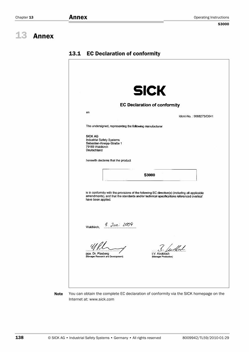
Chapter 13 Operating Instructions
S3000
138 © SICK AG • Industrial Safety Systems • Germany • All rights reserved 8009942/TL59/2010-01-29
Annex
13 Annex
13.1 EC Declaration of conformity
You can obtain the complete EC declaration of conformity via the SICK homepage on theInternet at: www.sick.com
Note

Operating Instructions Chapter 13
S3000
8009942/TL59/2010-01-29 © SICK AG • Industrial Safety Systems • Germany • All rights reserved 139
Annex
13.2 Manufacturer’s checklist
�Checklist for the manufacturer/installer for installing electro-sensitive protective equipment (ESPE)
Details about the points listed below must be present at least during initial commissioning — they are, however,dependent on the respective application, the specifications of which are to be controlled by the manufacturer/installer.
This checklist should be retained and kept with the machine documentation to serve as reference during recurringtests.
Have the safety rules and regulations been observed in compliance with the directives/ standardsapplicable to the machine?
Yes # No #
Are the applied directives and standards listed in the declaration of conformity? Yes # No #
Does the protective device comply with the required PL/SILCL and PFHd according toEN ISO 13�8491/EN 62�061 and the type according to EN 61�4961?
Yes # No #
Is the access to the hazardous area/hazardous point only possible through the protective field of theESPE?
Yes # No #
Have appropriate measures been taken to prevent (mechanical protection) or monitor unprotectedpresence in the hazardous area when protecting a hazardous area/hazardous point and havethese been secured against removal?
Yes # No #
Are additional mechanical protective measures fitted and secured against manipulation whichprevent reaching under, over or around the ESPE?
Yes # No #
Has the maximum stopping and/or run-down time of the machine been measured, specified anddocumented (at the machine and/or in the machine documentation)?
Yes # No #
Has the ESPE been mounted such that the required safety distance from the nearest hazardouspoint has been achieved?
Yes # No #
Are the ESPE devices correctly mounted and secured against manipulation after adjustment? Yes # No #
Are the required protective measures against electric shock in effect (protection class)? Yes # No #
Is the control switch for resetting the protective device (ESPE) or restarting the machine present andcorrectly installed?
Yes # No #
Are the outputs of the ESPE (OSSDs, ASInterface Safety at Work) integrated in compliance with therequired PL/SILCL according to EN ISO 13�849/EN 62�061 and does the integration comply withthe circuit diagrams?
Yes # No #
Has the protective function been checked in compliance with the test notes of this documentation? Yes # No #
Are the given protective functions effective at every setting of the operating mode selector switch? Yes # No #
Are the switching elements activated by the ESPE, e.g. contactors, valves, monitored? Yes # No #
Is the ESPE effective over the entire period of the dangerous state? Yes # No #
Once initiated, will a dangerous state be stopped when switching the ESPE on or off and whenchanging the operating mode, or when switching to another protective device?
Yes # No #
Has the information label “Important Information” for the daily check been attached so that it iseasily visible for the operator?
Yes # No #
This checklist does not replace the initial commissioning, nor the regular inspection by qualified safety personnel.

Chapter 13 Operating Instructions
S3000
140 © SICK AG • Industrial Safety Systems • Germany • All rights reserved 8009942/TL59/2010-01-29
Annex
13.3 GlossaryActive opto-electronic protective device responsive to diffuse reflection (e.g. S3000, seealso CLC/TS 61�4963)
The monitoring cases are switched using the control inputs. The S3000 Advanced has twostatic control inputs, the S3000 Professional two static control inputs and two universalcontrol inputs. The universal control inputs can be used both statically and dynamically (forincremental encoders).
A means by which the electro-sensitive protective equipment (ESPE) monitors the state ofcontrol devices which are external to the ESPE.
Protective field and warning field form a pair, the so-called field set.
Defines the functionality of the S3000. Five I/O modules (Standard, Advanced,Professional, Professional CMS and Remote) are available.
A component that produces electrical pulses in proportion to a movement. For thesepulses, various physical parameters can be derived, e.g. velocity, distance, etc.
Two S3000 that are configured to form a master/slave system using an EFI connectionwith the aid of the CDS. The control signals for monitoring case switching are applied tothe inputs on the master. The slave is connected to the master via EFI and receives fromthe master the input information for local monitoring case switching.
A field set (if necessary a simultaneous field set) is allocated to a monitoring case.Monitoring case switching is performed using the control inputs. In this way the S3000 canbe adapted to the operating mode of the machine or plant that it monitors.
The OSSD output is the switching output on the S3000. This is a semiconductor outputand is periodically tested for correct function. The S3000 has two OSSD outputs thatoperate in parallel; for safety reasons these must be evaluated using two channels.
The protective field secures the hazardous area on a machine or vehicle. As soon as thesafety laser scanner detects an object in the protective field, it switches the OSSDs to theoff status and thus initiates the shutdown of the machine or stop of the vehicle.
Reflection of luminance. A measure of the reflectivity is the reflectance defined as the ratioof the luminance reflected from a surface in the measuring direction and the luminance ofa completely matt white surface (white standard).
The minimum size of an object that is acquired by the protective device and is guaranteedby the manufacturer
The restart interlock is a protective device. In certain situations it prevents the machinefrom automatically restarting. This applies, e.g., after the scanner function has triggeredduring a dangerous machine state, after a change to the operating mode or the method ofactivation of the machine, or after the change to the start control device on the machine.
Contains the opto-electronic acquisition system. Three sensor heads are available (short-range with 4 m, medium-range with 5.5 m and long-range with 7 m scanning range).
Contains the configuration memory and all electrical connections. In this way the S3000can be easily replaced. After re-commissioning the configuration is loaded from the systemplug; the S3000 is then, normally, ready for use.
The warning field is a field with a radius of 49 m. Using this field larger areas can be con-trolled and simple switching functions (e.g. warning functions) triggered. The warning fieldis not allowed to be used for tasks related to the protection of people.
AOPDDR
Control input, dynamic,static, universal
External devicemonitoring (EDM)
Field set
I/O module
Incremental encoder
Master/slave
Monitoring case
OSSD
Protective field
Reflectivity
Resolution
Restart interlock
Sensor head
System plug
Warning field

Operating Instructions Chapter 13
S3000
8009942/TL59/2010-01-29 © SICK AG • Industrial Safety Systems • Germany • All rights reserved 141
Annex
13.4 List of tablesTab. 1: Functions of the I/O modules .................................................................................25
Tab. 2: Possible applications for the I/O modules .............................................................26
Tab. 3: Maximum protective field range short-range sensor head ...................................30
Tab. 4: Maximum protective field range medium-range sensor head ..............................30
Tab. 5: Maximum protective field range long-range sensor head.....................................30
Tab. 6: Permissible configuration of the restart interlock .................................................35
Tab. 7: Recommended multiple sampling..........................................................................36
Tab. 8: Level at the connections for the control inputs for complementarysampling...................................................................................................................38
Tab. 9: Truth table for 1-of-n sampling ...............................................................................39
Tab. 10: Figures from experience for the necessary input delay ........................................39
Tab. 11: Advantages and disadvantages of mounting methods.........................................52
Tab. 12: Size of the unprotected areas.................................................................................54
Tab. 13: Unprotected areas...................................................................................................64
Tab. 14: Pin assignments of the I/O modules ......................................................................75
Tab. 15: Use the cable entries supplied ...............................................................................79
Tab. 16: Recommended wire cross-sections........................................................................79
Tab. 17: Pin assignment: pre-assembled system plug ........................................................81
Tab. 18: 7segment display during and after the power up sequence on initialcommissioning.........................................................................................................97
Tab. 19: LED indication after the power up sequence.........................................................97
Tab. 20: 7segment display during and after the power up sequence onrecommissioning ................................................................................................. 100
Tab. 21: LED indication after the power up sequence...................................................... 101
Tab. 22: Operational status indicators during operation .................................................. 107
Tab. 23: LED error messages ............................................................................................. 108
Tab. 24: Error displays on the 7segment display ............................................................. 109
Tab. 25: Supplements for multiple sampling .................................................................... 116
Tab. 26: Data sheet S3000................................................................................................ 119
Tab. 27: Status information of the S3000 (Data from the S3000).................................. 127
Tab. 28: Control features on the S3000 (Data to the S3000) ......................................... 128
Tab. 29: Part numbers systems ......................................................................................... 132
Tab. 30: Part numbers sensor heads................................................................................. 133
Tab. 31: Part numbers I/O modules .................................................................................. 133
Tab. 32: Part numbers mounting kit .................................................................................. 133
Tab. 33: Part numbers system plugs ................................................................................. 134
Tab. 34: Part numbers service cables ............................................................................... 134
Tab. 35: Part numbers connecting cables......................................................................... 135
Tab. 36: Part numbers documentation.............................................................................. 135
Tab. 37: Part numbers safety relays/compact safety controller ...................................... 135
Tab. 38: Part numbers safety controllers .......................................................................... 136
Tab. 39: Part numbers network solutions.......................................................................... 136

Chapter 13 Operating Instructions
S3000
142 © SICK AG • Industrial Safety Systems • Germany • All rights reserved 8009942/TL59/2010-01-29
Annex
Tab. 40: Part numbers SDL connecting cables..................................................................136
Tab. 41: Part numbers miscellaneous................................................................................137
13.5 List of illustrationsFig. 1: Principle of operation, timeofflight measurement by the S3000.......................15
Fig. 2: Principle of operation of the S3000 — light pulses...............................................15
Fig. 3: Protective field and warning field...........................................................................16
Fig. 4: S3000 with three defined monitoring cases on an AGV.......................................17
Fig. 5: Sensor head, I/O module and system plug ...........................................................17
Fig. 6: Hazardous area protection with one monitored area ...........................................18
Fig. 7: Hazardous area protection with multiple monitored areas ..................................19
Fig. 8: Interior protection ...................................................................................................20
Fig. 9: Protecting hazardous points...................................................................................21
Fig. 10: Access protection....................................................................................................21
Fig. 11: Velocity-dependent protective field switching .......................................................22
Fig. 12: Collision protection .................................................................................................22
Fig. 13: Measurement application “contour measurement” .............................................23
Fig. 14: Protective field ranges of the sensor heads..........................................................24
Fig. 15: Available I/O modules.............................................................................................24
Fig. 16: Radii of protective field and warning field .............................................................27
Fig. 17: Configuring protective field and warning field.......................................................28
Fig. 18: Reading protective field and warning field ............................................................29
Fig. 19: Schematic diagram of contour as reference .........................................................31
Fig. 20: Contour as reference for vertical operation...........................................................32
Fig. 21: Contour as reference for horizontal operation ......................................................32
Fig. 22: Schematic of operation with restart interlock .......................................................34
Fig. 23: Tolerances on the dynamic inputs .........................................................................40
Fig. 24: Schematic layout of the monitoring case switching..............................................41
Fig. 25: S3000 and S300 in combination with a Flexi Soft modular safetycontroller..................................................................................................................43
Fig. 26: EFI network topologies............................................................................................45
Fig. 27: Operational status indicators on the S3000.........................................................45
Fig. 28: Horizontally mounted stationary application.........................................................48
Fig. 29: Risk of reaching over (mm).....................................................................................51
Fig. 30: Mounting methods for the scan plane...................................................................52
Fig. 31: Relationship between resolution and protective field mounting height ..............53
Fig. 32: Unprotected areas for stationary applications ......................................................54
Fig. 33: Example of mounting with cover plates.................................................................54
Fig. 34: Form of the recess ..................................................................................................55
Fig. 35: Access protection....................................................................................................56
Fig. 36: Safety distance to the hazardous area..................................................................58
Fig. 37: Stopping distance ...................................................................................................60
Fig. 38: Braking distance as a function of the vehicle velocity..........................................61

Operating Instructions Chapter 13
S3000
8009942/TL59/2010-01-29 © SICK AG • Industrial Safety Systems • Germany • All rights reserved 143
Annex
Fig. 39: Supplement due to lack of ground clearance........................................................62
Fig. 40: Diagram of ground clearance of the vehicle ..........................................................62
Fig. 41: Protective field width...............................................................................................63
Fig. 42: Mounting height.......................................................................................................63
Fig. 43: Unprotected areas for mobile applications............................................................64
Fig. 44: Fitting the S3000 in the vehicle trim......................................................................65
Fig. 45: Advancement for the switch timing ........................................................................66
Fig. 46: Example of advancing the timing for the switching...............................................67
Fig. 47: Prevent crawling beneath, standing behind, climbing over ..................................68
Fig. 48: Threaded holes for direct mounting .......................................................................69
Fig. 49: Mounting with mounting kit 1.................................................................................69
Fig. 50: Mounting with mounting kit 2.................................................................................70
Fig. 51: Mounting with mounting kit 3.................................................................................71
Fig. 52: Mounting with the Heavy Duty mounting bracket..................................................72
Fig. 53: Opposite mounting ..................................................................................................73
Fig. 54: Inclined, parallel mounting......................................................................................73
Fig. 55: Offset parallel mounting..........................................................................................73
Fig. 56: Mounting on a cross................................................................................................73
Fig. 57: Reverse mounting, parallel .....................................................................................73
Fig. 58: Screw terminal strip on the system plug................................................................75
Fig. 59: System plug SX0A-A0000B for S3000 Standard, S3000 Advanced andS3000 Remote ........................................................................................................78
Fig. 60: System plug SX0A-A0000D for S3000 Professional.............................................79
Fig. 61: Hazardous area protection with S3000 Standard.................................................82
Fig. 62: Access protection with S3000 Standard ...............................................................83
Fig. 63: Hazardous area protection with S3000 Advanced................................................83
Fig. 64: Access protection with S3000 Advanced ..............................................................84
Fig. 65: Vehicle monitoring with S3000 Standard ..............................................................84
Fig. 66: Velocity-dependent vehicle monitoring with S3000 Professional ........................85
Fig. 67: Mobile application with S3000 Professional CMS ................................................85
Fig. 68: Mobile application with S3000 Professional .........................................................86
Fig. 69: Mobile application with S3000 and S300 Advanced............................................87
Fig. 70: S3000 with UE100 series.......................................................................................88
Fig. 71: S3000 with UE1000 series.....................................................................................88
Fig. 72: Connection diagrams for restart interlock and external device monitoring.........89
Fig. 73: Connection diagram for restart interlock and external device monitoringwith series UE10......................................................................................................90
Fig. 74: Connection diagram for protective field switching using two static inputs..........90
Fig. 75: Connection diagram for protective field switching with four static inputs ...........91
Fig. 76: Connection diagram for protective field switching with static and dynamicinputs .......................................................................................................................91
Fig. 77: Connection diagram for protective field switching between two S3000with static inputs .....................................................................................................92

Chapter 13 Operating Instructions
S3000
144 © SICK AG • Industrial Safety Systems • Germany • All rights reserved 8009942/TL59/2010-01-29
Annex
Fig. 78: Connection diagram for protective field switching between two S3000with static and dynamic inputs...............................................................................93
Fig. 79: Connection diagram: protective field switching between an S3000 and anS300 with static and dynamic inputs ....................................................................94
Fig. 80: Connection diagram: protective field switching between two S3000 usinga Flexi Soft safety controller ...................................................................................95
Fig. 81: Connection diagram: protective field switching between S3000 and S300using a Flexi Soft safety controller .........................................................................95
Fig. 82: Configuration connection........................................................................................96
Fig. 83: Removing the fixing screws for the front screen.................................................103
Fig. 84: Inserting the rubber seal ......................................................................................103
Fig. 85: Depth for pressing in the seal ..............................................................................104
Fig. 86: Diagram of scanning ranges for various reflectances ........................................114
Fig. 87: Reset pulse requirements ....................................................................................115
Fig. 88: Diagram of the test pulse at the OSSDs ..............................................................117
Fig. 89: Voltage test after switching on the OSSDs ..........................................................117
Fig. 90: Shut-down test ......................................................................................................118
Fig. 91: Voltage test............................................................................................................118
Fig. 92: Dimensional drawing S3000 (mm) ......................................................................129
Fig. 93: Dimensional drawing, mounting kit 1, 2 and 3 (mm) .........................................130
Fig. 94: Dimensional drawing Heavy Duty mounting bracket ..........................................130
Fig. 95: Dimensional drawing of the scan plane (mm).....................................................131
Fig. 96: Dimensional drawing of the scan plane with mounting kit 3 (mm) ...................131

Operating Instructions Chapter 13
S3000
8009942/TL59/2010-01-29 © SICK AG • Industrial Safety Systems • Germany • All rights reserved 145
Annex

Chapter 13 Operating Instructions
S3000
146 © SICK AG • Industrial Safety Systems • Germany • All rights reserved 8009942/TL59/2010-01-29
Annex

Operating Instructions Chapter 13
S3000
8009942/TL59/2010-01-29 © SICK AG • Industrial Safety Systems • Germany • All rights reserved 147
Annex
SICK AG | Waldkirch | Germany | www.sick.com
8009
942/
TL59
/201
0-01
-29
∙ RV/
XX ∙
Prin
ted
in G
erm
any
(201
0-02
) ∙ S
ubje
ct to
cha
nge
with
out n
otic
e ∙ T
he s
peci
fied
prod
uct f
eatu
res
and
tech
nica
l dat
a do
not
repr
esen
t any
gua
rant
ee ∙
A4 s
w in
t34 Australia
Phone +61 3 9497 4100 1800 33 48 02 – tollfreeE-Mail [email protected]
Belgium/LuxembourgPhone +32 (0)2 466 55 66E-Mail [email protected]
BrasilPhone +55 11 3215-4900E-Mail [email protected]
Ceská RepublikaPhone +420 2 57 91 18 50E-Mail [email protected]
ChinaPhone +852-2763 6966E-Mail [email protected]
DanmarkPhone +45 45 82 64 00E-Mail [email protected]
DeutschlandPhone +49 211 5301-301E-Mail [email protected]
EspañaPhone +34 93 480 31 00E-Mail [email protected]
FrancePhone +33 1 64 62 35 00E-Mail [email protected]
Great BritainPhone +44 (0)1727 831121E-Mail [email protected]
IndiaPhone +91–22–4033 8333E-Mail [email protected]
IsraelPhone +972-4-999-0590E-Mail [email protected]
ItaliaPhone +39 02 27 43 41E-Mail [email protected]
JapanPhone +81 (0)3 3358 1341E-Mail [email protected]
NederlandsPhone +31 (0)30 229 25 44E-Mail [email protected]
Norge Phone +47 67 81 50 00E-Mail [email protected]
ÖsterreichPhone +43 (0)22 36 62 28 8-0E-Mail [email protected]
PolskaPhone +48 22 837 40 50E-Mail [email protected]
Republic of KoreaPhone +82-2 786 6321/4E-Mail [email protected]
Republika SlovenijaPhone +386 (0)1-47 69 990E-Mail [email protected]
RomâniaPhone +40 356 171 120 E-Mail [email protected]
RussiaPhone +7 495 775 05 34E-Mail [email protected]
SchweizPhone +41 41 619 29 39E-Mail [email protected]
SingaporePhone +65 6744 3732E-Mail [email protected]
SuomiPhone +358-9-25 15 800E-Mail [email protected]
SverigePhone +46 10 110 10 00E-Mail [email protected]
TaiwanPhone +886 2 2375-6288E-Mail [email protected]
TürkiyePhone +90 216 587 74 00E-Mail [email protected]
United Arab EmiratesPhone +971 4 8865 878E-Mail [email protected]
USA/Canada/MéxicoPhone +1(952) 941-6780 1 800-325-7425 – tollfreeE-Mail [email protected]
More representatives and agencies in all major industrial nations at www.sick.com