s7-200 modbus
DESCRIPTION
S7200 ModbusTRANSCRIPT

Using the USS Protocol Library to Control a MicroMaster Drive Chapter 11
333
Some drives require longer delays whenusing the parameter access instructions.The amount of time required for aparameter access is dependent on thedrive type and the parameter beingaccessed.After a USS_INIT instruction assigns Port 0to use the USS Protocol (or USS_INIT_P1for port 1), the S7-200 regularly polls allactive drives at the intervals shown inTable 11-1. You must set the time-outparameter of each drive to allow for thistask.
Table 11-1 Communications TimesBaudRate
Time Between Polls of Active Drives(with No Parameter Access InstructionsActive)1200 240 ms (maximum) times the number of drives2400 130 ms (maximum) times the number of drives4800 75 ms (maximum) times the number of drives9600 50 ms (maximum) times the number of drives
19200 35 ms (maximum) times the number of drives38400 30 ms (maximum) times the number of drives57600 25 ms (maximum) times the number of drives115200 25 ms (maximum) times the number of drives
TipOnly one USS_RPM_x or USS_WPM_x instruction can be active at a time. The Done output ofeach instruction should signal completion before user logic initiates a new instruction.Use only one USS_CTRL instruction for each drive.
Using the USS InstructionsTo use the USS protocol instructions in your S7-200 controller program, follow these steps:1. Insert the USS_INIT instruction in your program and execute the USS_INIT instruction forone scan only. You can use the USS_INIT instruction either to initiate or to change the USScommunications parameters.
When you insert the USS_INIT instruction, several hidden subroutines and interruptroutines are automatically added to your program.2. Place only one USS_CTRL instruction in your program for each active drive.
You can add as many USS_RPM_x and USS_WPM_x instructions as required, but onlyone of these can be active at a time.3. Allocate the V memory for the library instructionsby right-clicking (to get the menu) on the ProgramBlock node in the instruction tree.
Select the Library Memory option to display theLibrary Memory Allocation dialog box.4 C fi th d i t t t h th4. Configure the drive parameters to match thebaud rate and address used in the program. Figure 11-1 Allocating V Memory for theInstruction Library5. Connect the communications cable between the S7-200 and the drives.
Ensure that all of the control equipment, such as the S7-200, that is connected to the drivebe connected by a short, thick cable to the same ground or star point as the drive.CautionInterconnecting equipment with different reference potentials can cause unwanted currents toflow through the interconnecting cable. These unwanted currents can cause communicationserrors or damage equipment.Ensure that all equipment that is connected with a communications cable either shares acommon circuit reference or is isolated to prevent unwanted current flows.The shield must be tied to chassis ground or pin 1 on the 9-pin connector. It is recommendedthat you tie wiring terminal 2--0V on the MicroMaster drive to chassis ground.

S7-200 Programmable Controller System Manual
334
Instructions for the USS ProtocolUSS_INIT Instruction
The USS_INIT instruction (port 0) or USS_INIT_P1 (port 1)is used to enable and initialize, or to disable MicroMasterDrive communications. Before any other USS instructioncan be used, the USS_INIT instruction must be executedwithout errors. The instruction completes and the Done bit isset immediately, before continuing to the next instruction.The instruction is executed on each scan when the ENinput is on.Execute the USS_INIT instruction only once for eachchange in communications state. Use an edge detectioninstruction to pulse the EN input on. To change theinitialization parameters, execute a new USS_INITinstruction.The value for Mode selects the communications protocol:an input value of 1 assigns a port to USS protocol andenables the protocol, and an input value of 0 assigns port 0to PPI and disables the USS protocol.Baud sets the baud rate at 1200, 2400, 4800, 9600, 19200, 38400, 57600 or 115200. Baud rates57600 and 115200 are supported by S7-200 CPUs version 1.2 or later.Table 11-2 Parameters for the USS_INIT InstructionInputs/Outputs Data Type OperandsMode BYTE VB, IB, QB, MB, SB, SMB, LB, AC, Constant, *VD, *AC, *LDBaud, Active DWORD VD, ID, QD, MD, SD, SMD, LD, Constant, AC *VD, *AC, *LDDone BOOL I, Q, M, S, SM, T, C, V, LError BYTE VB, IB, QB, MB, SB, SMB, LB, AC, *VD, *AC, *LDActive indicates which drives are active.Some drives only support addresses 0through 30.Figure 11-2 shows the description andformat of the active drive input. Any drivethat is marked as Active is automaticallypolled in the background to control thedrive, collect status, and prevent seriallink time-outs in the drive
D0 Drive 0 active bit; 0 -- drive not active, 1 -- drive activeD1 Drive 1 active bit; 0 -- drive not active, 1 -- drive active...
MSB LSB30 29 28 3 2 1 0
D0D1D2D30 D29D3131
link time-outs in the drive.Refer to Table 11-1 to compute the timebetween status polls.
Figure 11-2 Format for the Active Drive Parameter
When the USS_INIT instruction completes, the Done output is turned on. The Error output bytecontains the result of executing the instruction. Table 11-6 defines the error conditions that couldresult from executing the instruction.Example: USS_INIT Subroutine
Network 1LD I0.0EUCALL USS_INIT, 1, 9600, 16#00000001,M0.0, VB10

Using the USS Protocol Library to Control a MicroMaster Drive Chapter 11
335
USS_CTRL InstructionThe USS_CTRL (port 0) or USS_CTRL_P1 (port 1)instruction is used to control an active MicroMaster drive.The USS_CTRL instruction places the selected commandsin a communications buffer, which is then sent to theaddressed drive (Drive parameter), if that drive has beenselected in the Active parameter of the USS_INITinstruction.Only one USS_CTRL instruction should be assigned toeach drive.Some drives report speed only as a positive value. If thespeed is negative, the drive reports the speed as positivebut reverses the D_Dir (direction) bit.The EN bit must be on to enable the USS_CTRLinstruction. This instruction should always be enabled.RUN (RUN/STOP) indicates whether the drive is on (1) oroff (0). When the RUN bit is on, the MicroMaster drivereceives a command to start running at the specified speedand direction. In order for the drive to run, the following mustbe true:- Drive must be selected as Active in USS_INIT.- OFF2 and OFF3 must be set to 0.- Fault and Inhibit must be 0.
When RUN is off, a command is sent to the MicroMasterdrive to ramp the speed down until the motor comes to astop. The OFF2 bit is used to allow the MicroMaster drive tocoast to a stop. The OFF3 bit is used to command theMicroMaster drive to stop quickly.The Resp_R (response received) bit acknowledges a response from the drive. All the Activedrives are polled for the latest drive status information. Each time the S7-200 receives a responsefrom the drive, the Resp_R bit is turned on for one scan and all the following values are updated.The F_ACK (fault acknowledge) bit is used to acknowledge a fault in the drive. The drive clearsthe fault (Fault) when F_ACK goes from 0 to 1.The DIR (direction) bit indicates in which direction the drive should move.Table 11-3 Parameters of the USS_CTRL InstructionInputs/Outputs Data Types OperandsRUN, OFF 2, OFF 3, F_ACK, DIR BOOL I, Q, M, S, SM, T, C, V, L, Power FlowResp_R, Run_EN, D_Dir, Inhibit,Fault BOOL I, Q, M, S, SM, T, C, V, LDrive, Type BYTE VB, IB, QB, MB, SB, SMB, LB, AC, *VD, *AC, *LD,ConstantError BYTE VB, IB, QB, MB, SB, SMB, LB, AC, *VD, *AC, *LDStatus WORD VW, T, C, IW, QW, SW, MW, SMW, LW, AC, AQW, *VD,*AC, *LDSpeed_SP REAL VD, ID, QD, MD, SD, SMD, LD, AC, *VD, *AC, *LD,ConstantSpeed REAL VD, ID, QD, MD, SD, SMD, LD, AC, *VD, *AC, *LD

S7-200 Programmable Controller System Manual
336
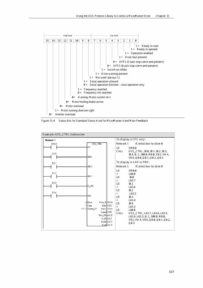
The Drive (drive address) input is the address of the MicroMaster drive to which the USS_CTRLcommand is to be sent. Valid addresses: 0 to 31The Type (drive type) input selects the type of drive. For a MicroMaster 3 (or earlier) drive, setType to 0. For a MicroMaster 4 drive, set Type to 1.Speed_SP (speed setpoint) is drive speed as a percentage of full speed. Negative values ofSpeed_SP cause the drive to reverse its direction of rotation. Range: --200.0% to 200.0%Error is an error byte that contains the result of the latest communications request to the drive.Table 11-6 defines the error conditions that could result from executing the instruction.Status is the raw value of the status word returned by the drive. Figure 11-3 shows the status bitsfor Standard Status Word and Main Feedback.Speed is drive speed as a percentage of full speed. Range: --200.0% to 200.0%Run_EN (RUN enable) indicates whether the drive is running (1) or stopped (0).D_Dir indicates the drive’s direction of rotation.Inhibit indicates the state of the inhibit bit on the drive (0 -- not inhibited, 1 -- inhibited). To clear theinhibit bit, the Fault bit must be off, and the RUN, OFF2, and OFF3 inputs must also be off.Fault indicates the state of the fault bit (0 -- no fault, 1 -- fault). The drive displays the fault code.(Refer to the manual for your drive). To clear the Fault bit, correct the cause of the fault and turnon the F_ACK bit.
15 14 13 12 11 10 9 8 7 6 5 4 3 2 1 0High byte Low byte
1 = Ready to start1 = Ready to operate1 = Operation enabled1 = Drive fault present0 = OFF2 (Coast stop command present)0 = OFF3 (Quick stop command present)1 = Switch-on inhibit
1 = Drive warning present1 = Not used (always 1)1 = Serial operation allowed0 = Serial operation blocked -- local operation only1 = Frequency reached0 = Frequency not reached
1 = Converter output is clockwise1 = Converter output is counter-clockwiseReserved for future use: These bits might not always be zero
Figure 11-3 Status Bits for Standard Status Word for MicroMaster 3 and Main Feedback
Using the USS Protocol Library to Control a MicroMaster Drive Chapter 11
337
15 14 13 12 11 10 9 8 7 6 5 4 3 2 1 0High byte Low byte
1 = Ready to start1 = Ready to operate1 = Operation enabled1 = Drive fault present0 = OFF2 (Coast stop command present)0 = OFF3 (Quick stop command present)1 = Switch-on inhibit
1 = Drive warning present1 = Not used (always 1)1 = Serial operation allowed0 = Serial operation blocked -- local operation only1 = Frequency reached0 = Frequency not reached
0= Warning: Motor current limit0= Motor holding brake active
0= Motor overload1 = Motor running direction right0= Inverter overload
Figure 11-4 Status Bits for Standard Status Word for MicroMaster 4 and Main Feedback
Example: USS_CTRL SubroutineTo display in STL only:Network 1 //Control box for drive 0LD SM0.0CALL USS_CTRL, I0.0, I0.1, I0.2, I0.3,I0.4, 0, 1, 100.0, M0.0, VB2, VW4,VD6, Q0.0, Q0.1, Q0.2, Q0.3To display in LAD or FBD:Network 1 //Control box for drive 0LD SM0.0= L60.0LD I0.0= L63.7LD I0.1= L63.6LD I0.2= L63.5LD I0.3= L63.4LD I0.4= L63.3LD L60.0CALL USS_CTRL, L63.7, L63.6, L63.5,L63.4, L63.3, 0, 1, 100.0, M0.0,VB2, VW4, VD6, Q0.0, Q0.1, Q0.2,Q0.3

S7-200 Programmable Controller System Manual
338
USS_RPM_x InstructionThere are three read instructions for the USS protocol:- USS_RPM_W (port 0) or USS_RPM_W_P1 (port 1)instruction reads an unsigned word parameter.- USS_RPM_D (port 0) or USS_RPM_D_P1 (port 1)instruction reads an unsigned double word parameter.- USS_RPM_R (port 0) or USS_RPM_R_P1 (port 1)instruction reads a floating-point parameter.
Only one read (USS_RPM_x) or write (USS_WPM_x)instruction can be active at a time.The USS_RPM_x transactions complete when theMicroMaster drive acknowledges receipt of the command,or when an error condition is posted. The logic scancontinues to execute while this process awaits a response.The EN bit must be on to enable transmission of a request,and should remain on until the Done bit is set, signalingcompletion of the process. For example, a USS_RPM_xrequest is transmitted to the MicroMaster drive on eachscan when XMT_REQ input is on. Therefore, the XMT_REQinput should be pulsed on through an edge detectionelement which causes one request to be transmitted foreach positive transition of the EN input.The Drive input is the address of the MicroMaster drive towhich the USS_RPM_x command is to be sent. Validaddresses of individual drives are 0 to 31.Param is the parameter number. Index is the index value of the parameter that is to be read. Valueis the parameter value returned. The address of a 16-byte buffer must be supplied to the DB_Ptrinput. This buffer is used by the USS_RPM_x instruction to store the results of the commandissued to the MicroMaster drive.When the USS_RPM_x instruction completes, the Done output is turned on and the Error outputbyte and the Value output contain the results of executing the instruction. Table 11-6 defines theerror conditions that could result from executing the instruction. The Error and Value outputs arenot valid until the Done output turns on.Table 11-4 Valid Operands for the USS_RPM_xInputs/Outputs Data Type OperandsXMT_REQ BOOL I, Q, M, S, SM, T, C, V, L, Power Flow conditioned by a rising edgedetection elementDrive BYTE VB, IB, QB, MB, SB, SMB, LB, AC, *VD, *AC, *LD, ConstantParam, Index WORD VW, IW, QW, MW, SW, SMW, LW, T, C, AC, AIW, *VD, *AC, *LD,ConstantDB_Ptr DWORD &VBValue WORD
DWORD, REALVW, IW, QW, MW, SW, SMW, LW, T, C, AC, AQW, *VD, *AC, *LDVD, ID, QD, MD, SD, SMD, LD, *VD, *AC, *LD
Done BOOL I, Q, M, S, SM, T, C, V, LError BYTE VB, IB, QB, MB, SB, SMB, LB, AC. *VD, *AC, *LD

Using the USS Protocol Library to Control a MicroMaster Drive Chapter 11
339
USS_WPM_x InstructionThere are three write instructions for the USS protocol:- USS_WPM_W (port 0) or USS_WPM_W_P1 (port 1)instruction writes an unsigned word parameter.- USS_WPM_D (port 0) or USS_WPM_D_P1 (port 1)instruction writes an unsigned double word parameter.- USS_WPM_R (port 0) or USS_WPM_R_P1 (port 1)instruction writes a floating-point parameter.
Only one read (USS_RPM_x) or write (USS_WPM_x)instruction can be active at a time.The USS_WPM_x transactions complete when theMicroMaster drive acknowledges receipt of the command,or when an error condition is posted. The logic scancontinues to execute while this process awaits a response.The EN bit must be on to enable transmission of a request,and should remain on until the Done bit is set, signalingcompletion of the process. For example, a USS_WPM_xrequest is transmitted to the MicroMaster drive on eachscan when XMT_REQ input is on. Therefore, the XMT_REQinput should be pulsed on through an edge detectionelement which causes one request to be transmitted foreach positive transition of the EN input.The EEPROM input enables writing to both RAM andEEPROM of the drive when it is on and only to the RAMwhen it is off. Note that this function is not supported byMM3 drives, so this input must be off.The Drive input is the address of the MicroMaster drive towhich the USS_WPM_x command is to be sent. Validaddresses of individual drives are 0 to 31.Param is the parameter number. Index is the index value ofthe parameter that is to be written. Value is the parametervalue to be written to the RAM in the drive. For MicroMaster3 drives, you can also write this value to the EEPROM of thedrive, based on how you have configured P971 (EEPROMStorage Control).The address of a 16-byte buffer must be supplied to the DB_Ptr input. This buffer is used by theUSS_WPM_x instruction to store the results of the command issued to the MicroMaster drive.When the USS_WPM_x instruction completes, the Done output is turned on and the Error outputbyte contains the result of executing the instruction. Table 11-6 defines the error conditions thatcould result from executing the instruction.When the EEPROM input is turned on, the instruction writes to both the RAM and the EEPROM ofthe drive. When the the input is turned off, the instruction writes only to the RAM of the drive.Because the MicroMaster 3 drive does not support this function, you must ensure that this input isoff in order to use this instruction with a MicroMaster 3 drive.Table 11-5 Valid Operands for the USS_WPM_x InstructionsInputs/Outputs Data Type OperandsXMT_REQ BOOL I, Q, M, S,SM,T,C,V,L, Power Flow conditioned by a rising edge detection elementEEPROM BOOL I, Q, M, S, SM, T, C, V, L, Power FlowDrive BYTE VB, IB, QB, MB, SB, SMB, LB, AC, *VD, *AC, *LD, ConstantParam, Index WORD VW, IW, QW, MW, SW, SMW, LW, T, C, AC, AIW, *VD, *AC, *LD, ConstantDB_Ptr DWORD &VBValue WORD
DWORD, REALVW, IW, QW, MW, SW, SMW, LW, T, C, AC, AQW, *VD, *AC, *LDVD, ID, QD, MD, SD, SMD, LD, *VD, *AC, *LD

S7-200 Programmable Controller System Manual
340
Table 11-5 Valid Operands for the USS_WPM_x Instructions, continuedOperandsData TypeInputs/Outputs
Done BOOL I, Q, M, S, SM, T, C, V, LError BYTE VB, IB, QB, MB, SB, SMB, LB, AC. *VD, *AC, *LDCautionWhen you use an USS_WPM_x instruction to update the parameter set stored in driveEEPROM, you must ensure that the maximum number of write cycles (approximately 50,000) tothe EEPROM is not exceeded.Exceeding the maximum number of write cycles will result in corruption of the stored data andsubsequent data loss. The number of read cycles is unlimited.If frequent writes to the drive parameters are required, then you should first set the EEPROMstorage control parameter in the drive to zero (for MicroMaster 3 drives) and turn off theEEPROM input for MicroMaster 4 drives.
Example: USS_RPM_x and USS_WPM_xNetwork 1 //The two contacts must have the//same address.LD I0.0= L60.0LD I0.0EU= L63.7LD L60.0CALL USS_RPM_W, L63.7, 0, 3, 0, &VB100,M0.0, VB10, VW200Network 2 //The two contacts must have thesame addressLD I0.1= L60.0LD I0.1EU= L63.7LDN SM0.0= L63.6LD L60.0CALL USS_WPM_W, L63.7, L63.6, 0, 971, 0, 1,&VB120, M0.1, VB11

Using the USS Protocol Library to Control a MicroMaster Drive Chapter 11
341
Sample Programs for the USS ProtocolExample: USS Instructions Sample Program that Correctly Displays in STL
Network 1 //Initialize USS Protocol://On the first scan, enable USS//protocol for port 0 at 19200//with drive address//”0” active.LD SM0.1CALL USS_INIT, 1, 19200, 16#00000001, Q0.0,VB1Network 2 //Control parameters for Drive 0LD SM0.0CALL USS_CTRL, I0.0, I0.1, I0.2, I0.3, I0.4, 0, 1,100.0, M0.0, VB2, VW4, VD6, Q0.1, Q0.2,Q0.3, Q0.4Network 3 //Read a Word parameter from Drive 0.//Read parameter 5 index 0.//1. Save the state of I0.5 to a// temporary location so that this// network displays in LAD.//2. Save the rising edge pulse of I0.5// to a temporary L location so that// it can be passed to the subroutine.LD I0.5= L60.0LD I0.5EU= L63.7LD L60.0CALL USS_RPM_W, L63.7, 0, 5, 0, &VB20, M0.1,VB10, VW12Network 4 //Write a Word parameter to Drive 0.//Write parameter 2000 index 0.LD I0.6= L60.0LD I0.6EU= L63.7LDN SM0.0= L63.6LD L60.0CALL USS_WPM_R, L63.7, L63.6, 0, 2000, 0, 50.0,&VB40, M0.2, VB14
Note: This STL code does not compile to LAD or FBD.

S7-200 Programmable Controller System Manual
342
USS Execution Error CodesTable 11-6 Execution Error Codes for the USS InstructionsError Codes Description
0 No error1 Drive did not respond2 A checksum error in the response from the drive was detected3 A parity error in the response from the drive was detected4 An error was caused by interference from the user program5 An illegal command was attempted6 An illegal drive address was supplied7 The communications port was not set up for USS protocol8 The communications port is busy processing an instruction9 The drive speed input is out of range10 The length of the drive response is incorrect11 The first character of the drive response is incorrect12 The length character in the drive response is not supported by USS instructions13 The wrong drive responded14 The DB_Ptr address supplied is incorrect15 The parameter number supplied is incorrect16 An invalid protocol was selected17 USS is active; change is not allowed18 An illegal baud rate was specified19 No communications: the drive is not ACTIVE20 The parameter or value in the drive response is incorrect or contains an error code21 A double word value was returned instead of the word value requested22 A word value was returned instead of the double word value requested
Connecting and Setting Up the MicroMaster Series 3 DriveConnecting the MicroMaster 3 Drive
You can use the standard PROFIBUS cable and connectors to connect the S7-200 to theMicroMaster Series 3 (MM3) drive. See Figure 11-5 for the proper cable bias and termination ofthe interconnecting cable.CautionInterconnecting equipment with different reference potentials can cause unwanted currents toflow through the interconnecting cable.These unwanted currents can cause communications errors or damage equipment.Be sure all equipment that you are about to connect with a communications cable either sharesa common circuit reference or is isolated to prevent unwanted current flows.The shield must be tied to chassis ground or pin 1 on the 9-pin connector. It is recommendedthat you tie wiring terminal 2--0V on the MicroMaster drive to chassis ground.

Using the USS Protocol Library to Control a MicroMaster Drive Chapter 11
343
A B A B A B A B
On OnA B A B
OffSwitch position = OnTerminated and biased Switch position = OffNo termination or bias Switch position = OnTerminated and biasedCable must be terminatedand biased at both ends.
390 220 390
BA
TxD/RxD +TxD/RxD -
Cable shield
63851
Networkconnector
Pin #
BA
TxD/RxD +TxD/RxD -
Cable shield
Networkconnector
ABTxD/RxD +
TxD/RxD -Cable shield
Bare shielding: approximately 12 mm (1/2 in.) mustcontact the metal guides of all locations.
63851
Pin #Switch position = Off: No termination or biasSwitch position = On: Terminated and biased
Figure 11-5 Bias and Termination of the Network Cable
Setting Up the MicroMaster 3 DriveBefore you connect a drive to the S7-200, you must ensure that the drive has the following systemparameters. Use the keypad on the drive to set the parameters:1. Reset the drive to factory settings (optional). Press the P key: P000 is displayed. Press theup or down arrow key until the display shows the P944. Press P to enter the parameter.
P944=12. Enable the read/write access to all parameters. Press the P key. Press the up or downarrow key until the display shows P009. Press P to enter the parameter.
P009=33. Check motor settings for your drive. The settings will vary according to the motor(s) beingused. Press the P key. Press the up or down arrow key until the display shows the motorsetting for your drive. Press P to enter the parameter.
P081=Nominal frequency of motor (Hz)P082=Nominal speed of motor (RPM)P083=Nominal current of motor (A)P084=Nominal voltage of motor (V)P085=Nominal power of motor (kW/HP)4. Set the Local/Remote control mode. Press the P key. Press the up or down arrow key untilthe display shows P910. Press P to enter the parameter.
P910=1 Remote control mode

S7-200 Programmable Controller System Manual
344
5. Set the Baud Rate of the RS--485 serial interface. Press the P key. Press the up or downarrow key until P092 appears. Press P to enter the parameter. Press the up or down arrowkey until the display shows the number that corresponds to the baud rate of your RS--485serial interface. Press P to enter.P092 3 (1200 baud)4 (2400 baud)5 (4800 baud)6 (9600 baud -- default)7 (19200 baud)
6. Enter the Slave address. Each drive (a maximum of 31) can be operated over the bus.Press the P key. Press the up or down arrow key until P091 appears. Press P to enter theparameter. Press the up or down arrow key until the display shows the slave address youwant. Press P to enter.P091=0 through 31.7. Ramp up time (optional). This is the time in seconds that it takes the motor to accelerate tomaximum frequency. Press the P key. Press the up or down arrow key until P002 appears.Press P to enter the parameter. Press the up or down arrow key until the display shows theramp up time you want. Press P to enter.P002=0--650.008. Ramp down time (optional). This is the time in seconds that it takes the motor to decelerateto a complete stop. Press the P key. Press the up or down arrow key until P003 appears.Press P to enter the parameter. Press the up or down arrow key until the display shows theramp down time you want. Press P to enter.P003=0--650.009. Serial Link Time-out. This is the maximum permissible period between two incoming datatelegrams. This feature is used to turn off the inverter in the event of a communicationsfailure.
Timing starts after a valid data telegram has been received. If a further data telegram is notreceived within the specified time period, the inverter will trip and display fault code F008.Setting the value to zero switches off the control. Use Table 11-1 to calculate the timebetween the status polls to the drive.Press the P key. Press the up or down arrow key until P093 appears. Press P to enter theparameter. Press the up or down arrow key until the display shows the serial link time-outyou want. Press P to enter.P093=0--240 (0 is default; time is in seconds)
10. Serial Link Nominal System Setpoint. This value can vary, but will typically correspond to 50Hz or 60 Hz, which defines the corresponding 100% value for PVs or SPs. Press the P key.Press the up or down arrow key until P094 appears. Press P to enter the parameter. Pressthe up or down arrow key until the display shows the serial link nominal system setpoint youwant. Press P to enter.P094=0--400.00
11. USS Compatibility (optional). Press the P key. Press the up or down arrow key until P095appears. Press P to enter the parameter. Press the up or down arrow key until the displayshows the number that corresponds to the USS compatibility you want. Press P to enter.P095 = 0 0.1 Hz resolution (default)1 0.01 Hz resolution
12. EEPROM storage control (optional). Press the P key. Press the up or down arrow key untilP971 appears. Press P to enter the parameter. Press the up or down arrow key until thedisplay shows the number that corresponds to the EEPROM storage control you want.Press P to enter.P971 = 0 Changes to parameter settings (including P971) are lost when power isremoved.1 (default) Changes to parameter settings are retained during periods whenpower is removed.
13. Operating display. Press P to exit out of parameter mode.

Using the USS Protocol Library to Control a MicroMaster Drive Chapter 11
345
Connecting and Setting Up the MicroMaster Series 4 DriveConnecting the MicroMaster 4 Drive
To make the connection to the MicroMaster Series 4 (MM4) drive, insert the ends of the RS-485cable into the two caged clamp, screwless terminals provided for USS operation. The standardPROFIBUS cable and connectors can be used to connect the S7-200.CautionInterconnecting equipment with different reference potentials can cause unwanted currents toflow through the interconnecting cable.These unwanted currents can cause communications errors or damage equipment.Be sure all equipment that you are about to connect with a communications cable either sharesa common circuit reference or is isolated to prevent unwanted current flows.The shield must be tied to chassis ground or pin 1 on the 9-pin connector. It is recommendedthat you tie wiring terminal 2--0V on the MicroMaster drive to chassis ground.As shown in Figure 11-6, the two wires atthe opposite end of the RS-485 cablemust be inserted into the MM4 driveterminal blocks. To make the cableconnection on a MM4 drive, remove thedrive cover(s) to access the terminalblocks. See the MM4 user manual fordetails about how to remove thecovers(s) of your specific drive.The terminal block connections arelabeled numerically. Using a PROFIBUSconnector on the S7-200 side, connectthe A terminal of the cable to the driveterminal 15 (for an MM420) or terminal30 (MM440). Connect the B terminal of
B (P) A (N)
30 (MM440). Connect the B terminal ofthe cable connector to terminal 14(MM420) or terminal 29 (MM440). Figure 11-6 Connecting to the MM420 Terminal BlockIf the S7-200 is a terminating node in the network, or if the connection is point-to-point, it isnecessary to use terminals A1 and B1 (not A2 and B2) of the connector since they allow thetermination settings to be set (for example, with DP connector type 6ES7 972--0BA40--0X40).CautionMake sure the drive covers are replaced properly before supplying power to the unit.If the drive is configured as the terminating node inthe network, then termination and bias resistorsmust also be wired to the appropriate terminalconnections. For example, Figure 11-7 shows anexample of the connections necessary fortermination and bias for the MM4 drive.
141521
120 ohm470 ohm 1.5K ohm
MM420
NP
0V+10 V
293021
120 ohm470 ohm 1.5K ohm
MM440
NP
0V+10 VFigure 11-7 Sample Termination and Bias

S7-200 Programmable Controller System Manual
346
Setting Up the MM4 DriveBefore you connect a drive to the S7-200, you must ensure that the drive has the following systemparameters. Use the keypad on the drive to set the parameters:1. Reset the drive to factory settings (optional): P0010=30P0970=1
If you skip this step, ensure that the following parameters are set to these values:USS PZD length: P2012 Index 0=2USS PKW length: P2013 Index 0=1272. Enable the read/write access to all parameters (Expert mode): P0003=33. Check motor settings for your drive: P0304=Rated motor voltage (V)P0305=Rated motor current (A)P0307=Rated motor power (W)P0310=Rated motor frequency (Hz)P0311=Rated motor speed (RPM)
The settings will vary according to the motor(s) being used.In order to set the parameters P304, P305, P307, P310, and P311, you must first setparameter P010 to 1 (quick commissioning mode). When you are finished setting theparameters, set parameter P010 to 0. Parameters P304, P305, P307, P310, and P311 canonly be changed in the quick commissioning mode.
4. Set the local/remote control mode: P0700 Index 0=55. Set selection of frequency setpoint to USS on COM Link: P1000 Index 0=56. Ramp up time (optional): P1120=0 to 650.00
This is the time in seconds that it takes the motor to accelerate to maximum frequency.7. Ramp down time (optional): P1121=0 to 650.00
This is the time in seconds that it takes the motor to decelerate to a complete stop.8. Set the serial link reference frequency: P2000=1 to 650 Hz9. Set the USS normalization: P2009 Index 0=010. Set the baud rate of the RS--485 serial interface: P2010 Index 0= 4 (2400 baud)5 (4800 baud)6 (9600 baud)7 (19200 baud8 (38400 baud)9 (57600 baud)12 (115200 baud)11. Enter the Slave address: P2011 Index 0=0 to 31
Each drive (a maximum of 31) can be operated over the bus.12. Set the serial link timeout: P2014 Index 0=0 to 65,535 ms(0=timeout disabled)
This is the maximum permissible period between two incoming data telegrams. This featureis used to turn off the inverter in the event of a communications failure. Timing starts after avalid data telegram has been received. If a further data telegram is not received within thespecified time period, the inverter will trip and display fault code F0070. Setting the value tozero switches off the control. Use Table 11-1 to calculate the time between the status pollsto the drive.13. Transfer the data from RAM to EEPROM:
P0971=1 (Start transfer) Save the changes to the parameter settings to EEPROM

347
Using the Modbus Protocol LibraryThe STEP 7--Micro/WIN Instruction Libraries make communicating to Modbus devices easier byincluding pre-configured subroutines and interrupt routines that are specifically designed forModbus communications. With the Modbus Protocol Instructions, you can configure the S7-200 toact as a Modbus master or slave device.You find these instructions in the Libraries folder of the STEP 7--Micro/WIN instruction tree. Whenyou put a Modbus instruction in your program, one or more associated subroutines areautomatically added to your project.Siemens Libraries are sold on a separate CD, STEP 7--Micro/WIN Add-On: Instruction Library,with the order number 6ES7 830--2BC00--0YX0. After version 1.1 of the Siemens Library ispurchased and installed, any subsequent STEP 7--Micro/WIN V3.2x and V4.0 upgrade that youinstall will also upgrade your libraries automatically at no additional cost (when library additions ormodifications are made).
In This ChapterOverview 348. . . . . . . . . . . . . . . . . . . . . . . . . . . . . . . . . . . . . . . . . . . . . . . . . . . . . . . . . . . . . . . . . . . . . . .Requirements for Using Modbus Protocol 348. . . . . . . . . . . . . . . . . . . . . . . . . . . . . . . . . . . . . . . . . . .Initialization and Execution Time for Modbus Protocol 349. . . . . . . . . . . . . . . . . . . . . . . . . . . . . . . . .Modbus Addressing 350. . . . . . . . . . . . . . . . . . . . . . . . . . . . . . . . . . . . . . . . . . . . . . . . . . . . . . . . . . . . . .Using the Modbus Master Instructions 351. . . . . . . . . . . . . . . . . . . . . . . . . . . . . . . . . . . . . . . . . . . . . .Using the Modbus Slave Instructions 352. . . . . . . . . . . . . . . . . . . . . . . . . . . . . . . . . . . . . . . . . . . . . . .Instructions for the Modbus Protocol 353. . . . . . . . . . . . . . . . . . . . . . . . . . . . . . . . . . . . . . . . . . . . . . . .Advanced Topics 362. . . . . . . . . . . . . . . . . . . . . . . . . . . . . . . . . . . . . . . . . . . . . . . . . . . . . . . . . . . . . . . .

S7-200 Programmable Controller System Manual
348
OverviewSTEP 7--Micro/WIN Instruction Libraries make communicating to Modbus master and slavedevices easier by including pre-configured subroutines and interrupt routines that are specificallydesigned for Modbus communications.Modbus slave instructions can configure the S7-200 to act as a Modbus RTU slave device andcommunicate to Modbus master devices.Modbus master instructions can configure the S7-200 to act as a Modbus RTU master device andcommunicate to one or more Modbus slave devices.The Modbus instructions are installed into the libraries folder in the STEP 7--Micro/WIN instructiontree. These instructions enable the S7-200 to act as a Modbus device. When you place a Modbusinstruction in your program, one or more associated subroutines are automatically added to yourproject.There are two versions of the Modbus master protocol library. One version uses port 0 of the CPUand the other uses port 1 of the CPU. The port 1 library has a _P1 appended to the POU names(for example, MBUS_CTRL_P1) to denote that the POU utilizes port 1 on the CPU. The twoModbus master libraries are identical in all other respects.The Modbus slave library only supports port 0 communication.
Requirements for Using Modbus ProtocolThe Modbus Master Protocol instructions use the following resources from the S7-200:- Initializing the Modbus Slave Protocol dedicates the specific CPU port for Modbus MasterProtocol communications.
When the CPU port is being used for Modbus Master Protocol communications, it cannot beused for any other purpose, including communications with STEP 7--Micro/WIN. TheMBUS_CTRL instruction controls assignment of Port 0 to Modbus Master Protocol or PPI.The MBUS_CTRL_P1 instruction (from the port 1 library) controls assignment of Port 1 toModbus Master Protocol or PPI- The Modbus Master Protocol instructions affect all of the SM locations associated withFreeport communications port in use- The Modbus Master Protocol instructions use 3 subroutines and 1 interrupt routine.- The Modbus Master Protocol instructions require about 1620 bytes of program space forthe two Modbus Master instructions and the support routines.- The variables for the Modbus Master Protocol instructions require a 284 byte block of Vmemory. The starting address for this block is assigned by the user and is reserved forModbus variables.- The S7-200 CPU must be firmware revision 2.00 or greater to support the Modbus MasterProtocol Library (CPU MLFB 21x--2xx23--0XB0)- The Modbus Master Library uses the user interrupts for some functions. The user interruptsmust not be disabled by the user program.TipTo change the operation of the CPU communications port back to PPI so that you cancommunicate with STEP 7-Micro/WIN, you can do one of the following:-- Set the Mode parameter of the MBUS_CTRL instruction to a zero (0).-- Set the mode switch on the S7-200 to STOP mode position.Either of these methods will set the CPU communications port to communicate withSTEP 7--Micro/WIN.

Using the Modbus Protocol Library Chapter 12
349
The Modbus Slave Protocol instructions use the following resources from the S7-200:- Initializing the Modbus Slave Protocol dedicates Port 0 for Modbus Slave Protocolcommunications.
When Port 0 is being used for Modbus Slave Protocol communications, it cannot be usedfor any other purpose, including communications with STEP 7--Micro/WIN. The MBUS_INITinstruction controls assignment of Port 0 to Modbus Slave Protocol or PPI.- The Modbus Slave Protocol instructions affect all of the SM locations associated withFreeport communications on Port 0.- The Modbus Slave Protocol instructions use 3 subroutines and 2 interrupts.- The Modbus Slave Protocol instructions require 1857 bytes of program space for the twoModbus Slave instructions and the support routines.- The variables for the Modbus Slave Protocol instructions require a 779-byte block of Vmemory. The starting address for this block is assigned by the user and is reserved forModbus variables.TipTo change the operation of Port 0 back to PPI so that you can communicate withSTEP 7-Micro/WIN, you can do one of the following:-- Use another MBUS_INIT instruction to reassign Port 0.-- Set the mode switch on the S7-200 to STOP mode.Either of these methods will set the parameters for Port 0 so that you can communicate withSTEP 7--Micro/WIN.
Initialization and Execution Time for Modbus ProtocolModbus Master Protocol -- The Modbus Master Protocol requires a small amount of time everyscan to execute the MBUS_CTRL instruction. The time will be about 1.11 milliseconds when theMBUS_CTRL is initializing the Modbus Master (first scan), and about 0.41 milliseconds onsubsequent scans.The scan time is extended when the MBUS_MSB subroutine executes a request. Most of the timeis spent calculating the Modbus CRC for the request and the response. The CRC (CyclicRedundancy Check) insures the integrity of the communications message. The scan time isextended by about 1.85 milliseconds for each word in request and in the response. A maximumrequest/response (read or write of 120 words) extends the scan time to approximately 222milliseconds. A read request extends the scan mainly when the response is received from theslave, and to a lesser extent when the request is sent. A write request extends the scan mainlywhen the data is sent to the slave, and to a lesser extent when the response is received.Modbus Slave Protocol -- Modbus communications utilize a CRC (cyclic redundancy check) toinsure the integrity of the communications messages. The Modbus Slave Protocol uses a table ofprecalculated values to decrease the time required to process a message. The initialization of thisCRC table requires about 240 milliseconds. This initialization is done inside the MBUS_INITsubroutine and is normally done in the first scan of the user program after entering RUN mode.You are responsible for resetting the watchdog timer and keeping the outputs enabled (if requiredfor expansion modules) if the time required by the MBUS_INIT subroutine and any other userinitialization exceeds the 500 millisecond scan watchdog. The output module watchdog timer isreset by writing to the outputs of the module. See the Watchdog Reset Instruction in Chapter 6.The scan time is extended when the MBUS_SLAVE subroutine services a request. Since most ofthe time is spent calculating the Modbus CRC, the scan time is extended by about 420microseconds for every byte in the request and in the response. A maximum request/response(read or write of 120 words) extends the scan time by approximately 100 milliseconds.