sab 355 screw compressor units - · pdf file1. spare parts list 1.1.1. sab 355 pos. item part...
TRANSCRIPT
Spare p
arts man
ual
SAB 355Screw compressor units
en

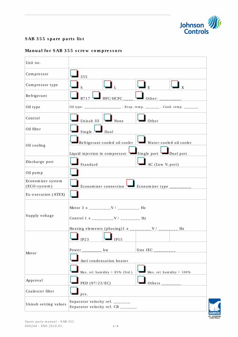
SAB 355 spare parts list
Manual for SAB 355 screw compressors
Unit no.
Compressor 355
Compressor type S L E X
Refrigerant R717 HFC/HCFC ____ Other: _________
Oil type Oil type: __________________ . Evap. temp. _______ . Cond. temp. _______
Control Unisab III None Other
Oil filter Single Dual
Oil coolingRefrigerant-cooled oil cooler Water-cooled oil cooler
Liquid injection in compressor Single port Dual port
Discharge port Standard AC (Low Vi port)
Oil pump
Economizer system(ECO-system) Economizer connection Economizer type _________
Ex-execution (ATEX)
Supply voltage
Motor 3 x _________V / _________ Hz
Control 1 x _________V / ________ Hz
Heating elements (phasing)1 x _________V / ________ Hz
Motor
IP23 IP55
Power ________ kw Size IEC _________
Anti condensation heater
Max. rel. humidity = 85% (Std.) Max. rel. humidity = 100%
Approval PED (97/23/EC) Others ________
Coalescer filter pcs.
Unisab setting valuesSeparator velocity ref. _______Separator velocity ref. CR _______
Spare parts manual - SAB 355006244 - ENG 2010.01. 1/9
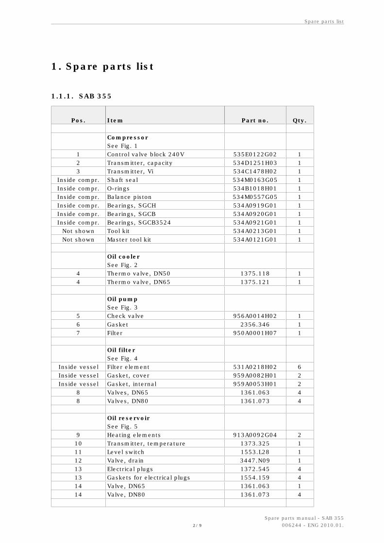
1. Spare parts list
1.1.1. SAB 355
Pos. Item Part no. Qty.
CompressorSee Fig. 1
1 Control valve block 240V 535E0122G02 12 Transmitter, capacity 534D1251H03 13 Transmitter, Vi 534C1478H02 1
Inside compr. Shaft seal 534M0163G05 1Inside compr. O-rings 534B1018H01 1Inside compr. Balance piston 534M0557G05 1Inside compr. Bearings, SGCH 534A0919G01 1Inside compr. Bearings, SGCB 534A0920G01 1Inside compr. Bearings, SGCB3524 534A0921G01 1
Not shown Tool kit 534A0213G01 1Not shown Master tool kit 534A0121G01 1
Oil coolerSee Fig. 2
4 Thermo valve, DN50 1375.118 14 Thermo valve, DN65 1375.121 1
Oil pumpSee Fig. 3
5 Check valve 956A0014H02 16 Gasket 2356.346 17 Filter 950A0001H07 1
Oil filterSee Fig. 4
Inside vessel Filter element 531A0218H02 6Inside vessel Gasket, cover 959A0082H01 2Inside vessel Gasket, internal 959A0053H01 2
8 Valves, DN65 1361.063 48 Valves, DN80 1361.073 4
Oil reservoirSee Fig. 5
9 Heating elements 913A0092G04 210 Transmitter, temperature 1373.325 111 Level switch 1553.L28 112 Valve, drain 3447.N09 113 Electrical plugs 1372.545 413 Gaskets for electrical plugs 1554.159 414 Valve, DN65 1361.063 114 Valve, DN80 1361.073 4
Spare parts list
2/9
Spare parts manual - SAB 355006244 - ENG 2010.01.
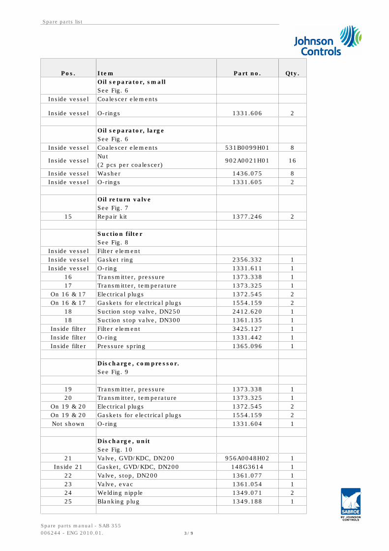
Pos. Item Part no. Qty.
Oil separator, smallSee Fig. 6
Inside vessel Coalescer elements
Inside vessel O-rings 1331.606 2
Oil separator, largeSee Fig. 6
Inside vessel Coalescer elements 531B0099H01 8
Inside vesselNut(2 pcs per coalescer)
902A0021H01 16
Inside vessel Washer 1436.075 8Inside vessel O-rings 1331.605 2
Oil return valveSee Fig. 7
15 Repair kit 1377.246 2
Suction filterSee Fig. 8
Inside vessel Filter element Inside vessel Gasket ring 2356.332 1Inside vessel O-ring 1331.611 1
16 Transmitter, pressure 1373.338 117 Transmitter, temperature 1373.325 1
On 16 & 17 Electrical plugs 1372.545 2On 16 & 17 Gaskets for electrical plugs 1554.159 2
18 Suction stop valve, DN250 2412.620 118 Suction stop valve, DN300 1361.135 1
Inside filter Filter element 3425.127 1Inside filter O-ring 1331.442 1Inside filter Pressure spring 1365.096 1
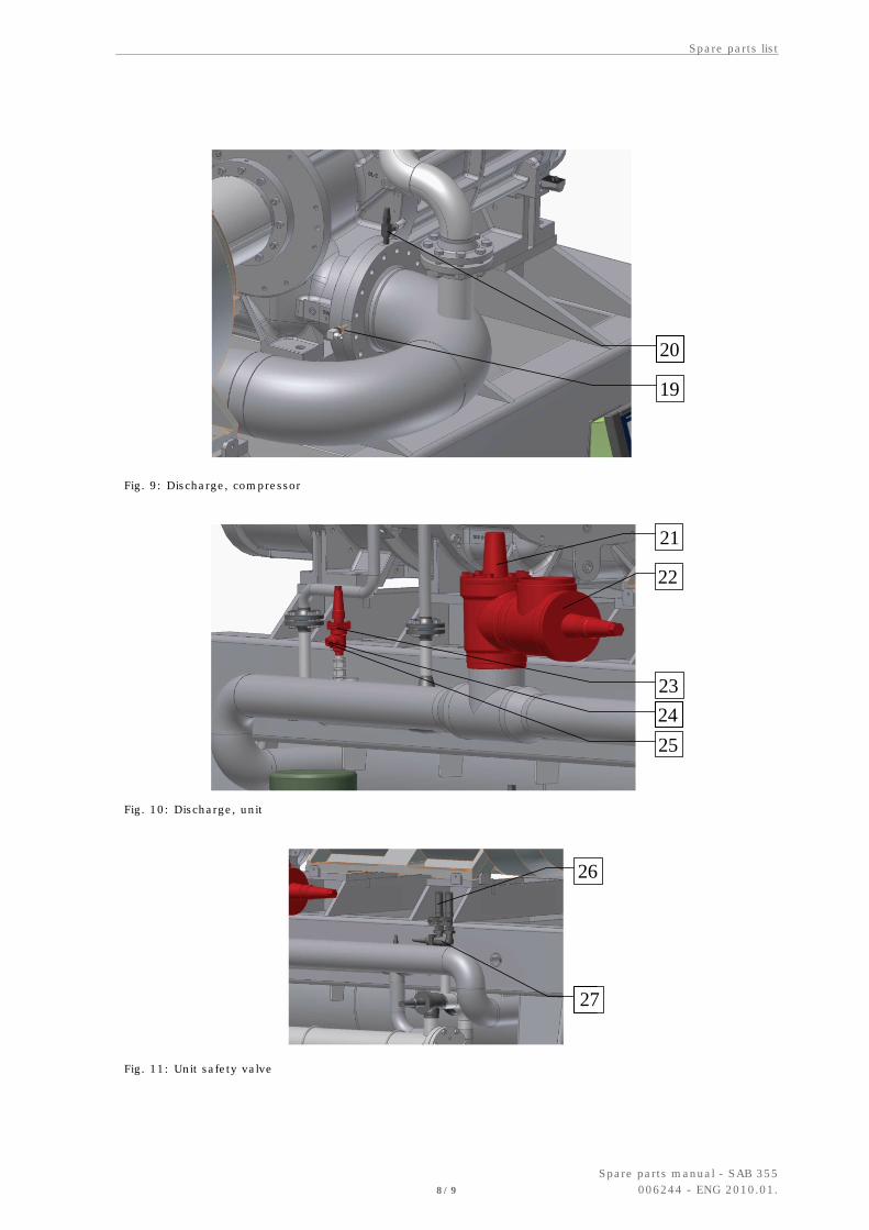
Discharge, compressor.See Fig. 9
19 Transmitter, pressure 1373.338 120 Transmitter, temperature 1373.325 1
On 19 & 20 Electrical plugs 1372.545 2On 19 & 20 Gaskets for electrical plugs 1554.159 2Not shown O-ring 1331.604 1
Discharge, unitSee Fig. 10
21 Valve, GVD/KDC, DN200 956A0048H02 1Inside 21 Gasket, GVD/KDC, DN200 148G3614 1
22 Valve, stop, DN200 1361.077 123 Valve, evac 1361.054 124 Welding nipple 1349.071 225 Blanking plug 1349.188 1
Spare parts list
Spare parts manual - SAB 355006244 - ENG 2010.01. 3/9

Pos. Item Part no. Qty.
Safety systemsSee Fig. 11 and Fig. 12
Unit safety valve 26 - Safety valve, 22 bar 2416.241 226 - Safety valve, 24 bar 2416.264 227 - Stop valve, double 1364.353 128 Compressor safety valve 1364.347 1 to 329 Pilot valve, BSV 20 bar 2416.203 1 to 329 Pilot valve, BSV 22 bar 2416.224 1 to 329 Pilot valve, BSV 24 bar 2416.315 1 to 3 Coupling Coupling hub, SR52 size 375, compr. 1524.366 1 Coupling hub, SR52 size 375, motor 1524.364 1 Coupling spacer, SR52 size 375 1524.362 1 Coupling guard, SR52 size 375 2158.L02 1 Coupling hub, SR52 size 450, compr. 1524.365 1 Coupling hub, SR52 size 450, motor 1524.363 1 Coupling spacer, SR52 size 450 1524.361 1 Coupling guard, SR52 size 450 2158.L01 1
1
2
3
Fig. 1: Compressor
Spare parts list
4/9
Spare parts manual - SAB 355006244 - ENG 2010.01.

4
Fig. 2: Oil cooler
7
6
5
Fig. 3: Oil pump
Spare parts list
Spare parts manual - SAB 355006244 - ENG 2010.01. 5/9

8
Fig. 4: Oil filter
9
13 14
101112
9
Fig. 5: Oil reservoir
Spare parts list
6/9
Spare parts manual - SAB 355006244 - ENG 2010.01.

Fig. 6: Oil separator
15
Fig. 7: Oil return valve
18
16
17
Fig. 8: Suction filter
Spare parts list
Spare parts manual - SAB 355006244 - ENG 2010.01. 7/9
19
20
Fig. 9: Discharge, compressor
23
22
21
2425
Fig. 10: Discharge, unit
27
26
Fig. 11: Unit safety valve
Spare parts list
8/9
Spare parts manual - SAB 355006244 - ENG 2010.01.

29
28
Fig. 12: Safety valve and pilot valve
Spare parts list
Spare parts manual - SAB 355006244 - ENG 2010.01. 9/9