sabre - lucy switchgear sensors 29 vi. watchdog for relays 29 vii. operation counter 29 viii....
TRANSCRIPT

providing intelligent solutions
SabreVacuum circuit breaker ring main unit up to 24kVwith automation and remote control options

Page 2
Sabre catalogueTable of contents
Introduction to Lucy Switchgear 3
Product panorama 4
Introduction to Sabre 5
Installation and operating conditions 6
Safety features 6
Application example 9
Standards 9
The Sabre range 10
Non extensible range 10
Extensible range 12
Mounting style 16
Product characteristics 18
i. Product presentation 18ii. User interface and interlocking mechanism 19iii. Ring switch 20iv. Vacuum circuit breaker 20v. Circuit breaker protection 21 a. TLF 21 b. Protection relays 23vi. Protection CTs for TLF and relays 26vii. Bushings 26
Options and accessories 27i. Secondary injection 27ii. Actuators (motors) 27iii. Cable boxes, glands and accessories 28iv. Bus bar couplings 29v. MV sensors 29vi. Watchdog for relays 29vii. Operation counter 29 viii. Castell locks 29ix. Protection trip remote indicator 29x. Shunt trip coils 30xi. Earth fault indicators (EFI) 30
Cable terminations 31
Air metering unit (AMU) 32
Remote terminal unit (RTU) 33
Technical data sheet 35
Dimensions 37
Models, options and accessories 47
Order forms 54

Page 3
AEGIS
1965 1970 1975 1980 1985 1990 1995 2000 2005 2010 2015
SCIMITAR
TRIDENT
Ring main unit range evolution
SABRE
Introduction to Lucy Switchgear
Lucy Switchgear is a global leader in switching, protection and automation solutions for electrical distribution systems with over 100 years’ industry experience. From its modest beginnings in street lighting, the company today is a specialist in secondary power distribution, engineering high-performance medium voltage switchgear for utility, industrial and commercial applications with a broad product portfolio that includes overhead line equipment and retrofit and automation solutions.
Engineering excellence coupled with state of the art technology make Lucy Switchgear one of the few
companies that can offer truly bespoke solutions. With the capability to manufacture equipment to suit almost any location, climate or situation, Lucy Switchgear can also offer maintenance packages and dedicated after sales support throughout the product lifecycle. A specialist UK based research and development facility ensures that Lucy Switchgear’s products are always at the cutting edge of technology enabling rapid response to evolving technical and market demands of customers. All of our purpose built, state of the art manufacturing facilities espouse the latest international Quality and Environmental standards. The global profile of Lucy Switchgear is emphasised through manufacturing facilities in the United Arab Emirates, Saudi Arabia and India, offices in China, Dubai, Malaysia and South Africa and an established global network of industrial partners and contractors operating in over 50 countries worldwide.

Page 4
Product panoramaLucy medium voltage and high voltage range
Range name Trident Scimitar Sabre Aegis Rapier GX Rapier AX Rapier DSB
Type Ring main unit Switch disconnector
Rated voltage 15.5kV
17.5kV 24kV 24kV 38kV 36kV 145kV
(up to)
Mode of fault current Fuse Fuse Vacuum Vacuum - - - interruption
Insulation Oil SF6 Air Air
medium
Rated current 630A 800A 2500A
(up to)
Mounting Ground / Transformer Ground Pole Pole Structure
Installation Indoor / Outdoor Outdoor
Operation Local / Remote

Page 5
Introduction to Sabre
Characteristics:
• Up to 24kV and 630Amps ratings
• Non extensible, extensible and modular range
• Switching functions enclosed in a SF6 gas insulated steel tank, sealed for life
• Intuitive single line mimic diagram for simple and safe operation
• Integrated earth and test facility for easy and safe cable test without removing cable connections
• Choice of TLF (time limit fuses) or self/auxiliary powered relay protection
• Anti-reflex mechanism to prevent load break switch opening under fault conditions
• Fully interlocked operation with padlocking facility for maximum operator protection
• Freestanding and transformer mounted units
• Actuators (motorised) for ring switches and circuit breakers
• Seamless integration with SCADA network for remote operation and control
• Maintenance free with 30 years life expectancy
Sabre ring main units are designed for secondary distribution networks up to 24kV. The range is an ideal solution for indoor/outdoor compact substations and is available in non-extensible, extensible and modular formats to suit various application requirements. All of the switching functions are insulated with SF6 gas and sealed in a stainless steel tank with a leakage rate of less than 0.1% per year.
The structural tank welding is performed by a robotic welding process ensuring high reliability with a product life expectancy of more than 30 years. The housing is fully treated using zinc coated steel and electrostatically applied oven cured paint to resist degradation from pollution and harsh climatic conditions.
The transformer protection is by vacuum circuit breaker. On request, the units can be supplied with integrated automation for remote monitoring and control functions.
Page 6
Installation and operating conditions
Safety features
• IP54 outdoor installation (kiosk not necessary)
• Ambient temperature for operation: -25°C to 40°C (50°C optional)
• Average value over 24 hours max: 40°C
• Maximum altitude for operation without derating:1000m
• Insulation medium: SF6 Gas
• Interruption medium: Vacuum
Operation mechanism
The operating mechanism of the ring switches and circuit breaker incorporates mechanical interlocks and padlocking facilities which make it impossible to simultaneously close the ring switch/circuit breaker and the earth switch.
Anti-reflex mechanism
Anti-reflex mechanisms on ring switches ensure a time delay between switching operations.
Internal arc withstand
Sabre gas tanks are fully internal arc rated and this feature is also available on the cable boxes (optional) to ensure maximum operator safety in the event of internal faults. The gas tanks are available in AF (front), AFL (front and lateral) and AFLR (front, lateral and rear) ratings.
For more details on internal arc classification (IAC) ratings, please refer to the technical data sheet.

Page 7
Cable earth and test facility (E&T)
E&T feature is used for testing cable insulation and to locate faults in the circuit without the need to remove the main cables from the cable box.
The cable test access cover is fully interlocked and cannot be opened until the ring switch or circuit breaker switch is in the Earth ON position. The test bushings are earthed with a star bar which has to be removed for cable tests.
Cable boxes
The cable boxes are located laterally or at the rear of the ring main unit. Factory mounted protection CTs are provided on the circuit breaker cable bushings for ease of installation and to avoid any potential damage to the CT during transit and connection. For additional operator safety, the cable boxes are earthed and can be interlocked to allow access to the operator only if the function is in the Earth ON position. There is an option to supply these cable boxes with internal arc rating as per IEC standards (for further information, please refer to the cable box, gland and accessories section).
Ring switches: E&T is a standard feature located at the bottom of the unit.
Vacuum circuit breakers: E&T is an optional feature only on 630A VCB and is located at the top of the unit

Page 8
Safety features
VPIS
VPIS (Voltage Presence Indication System) is an optional feature in the Sabre range. The VPIS receives a voltage signal through the voltage divider built into the cable bushings. They can also be fitted with neon lights and momentary latching push buttons to show voltage presence without needing external testing probes.
Two types of voltage presence indication devices are offered:• Pfisterer sockets• Neon indicators with push-to-test buttons and
phase comparator sockets
Gas pressure indicator
• A gas pressure indicator is fitted to the tank which has green and red sectors to indicate the minimum permissible pressure for safe operation
• An optional remote gas pressure alarm (1N/O) can be specified to alert the operator in the event of gas pressure falling below the permissible operable limit
Pfisterer sockets
Neon indicator with push-to-test buttons

Page 9
Application examples
The key areas of application are
• Energy i. Generation: wind power, solar power
ii. Distribution: compact substations
• Infrastructure: tunnels, airports, ports, underground railway stations
• Commercial buildings: hospitals, shopping centres, hotels, office buildings, data centres
• Industries: water and waste water, mining, minerals, automotive, iron and steel, paper and pulp, cement and petroleum
International Standards IEC 62271-1 IEC 62271-100 IEC 62271-102 IEC 62271-103 IEC 62271-200 ENA TS 41-36
Standards
Page 10
The Sabre range
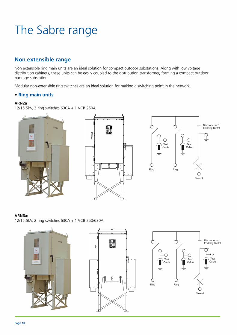
Non extensible range
Non extensible ring main units are an ideal solution for compact outdoor substations. Along with low voltage distribution cabinets, these units can be easily coupled to the distribution transformer, forming a compact outdoor package substation.
Modular non-extensible ring switches are an ideal solution for making a switching point in the network.
• Ring main units
VRN2a 12/15.5kV, 2 ring switches 630A + 1 VCB 250A
VRN6a: 12/15.5kV, 2 ring switches 630A + 1 VCB 250/630A
Page 11
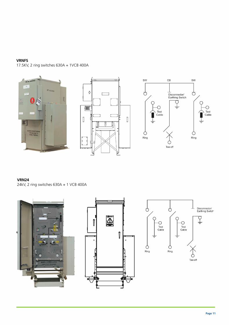
VRNFS 17.5KV, 2 ring switches 630A + 1VCB 400A
VRN24 24kV, 2 ring switches 630A + 1 VCB 400A

Page 12
The Sabre range
Extensible range
The extensible range is used to add another function on the left, right or both sides of switchgear installed in secondary networks. This is an ideal solution to allow future upgrades to systems when extra capacity is required. The units can be easily extended in any combination on site without specific tooling or floor preparation and without the need to transfer SF6 gas. The extensible range is designed to be mounted outdoors without needing a kiosk.
• Modular ring switch
DSN6a 12/15.5kV, 2 ring switches 630A
The units are extended as shown in the diagram below:
All the extensible units are available in the following configurations:• Left hand• Right hand • Both sides
Page 13
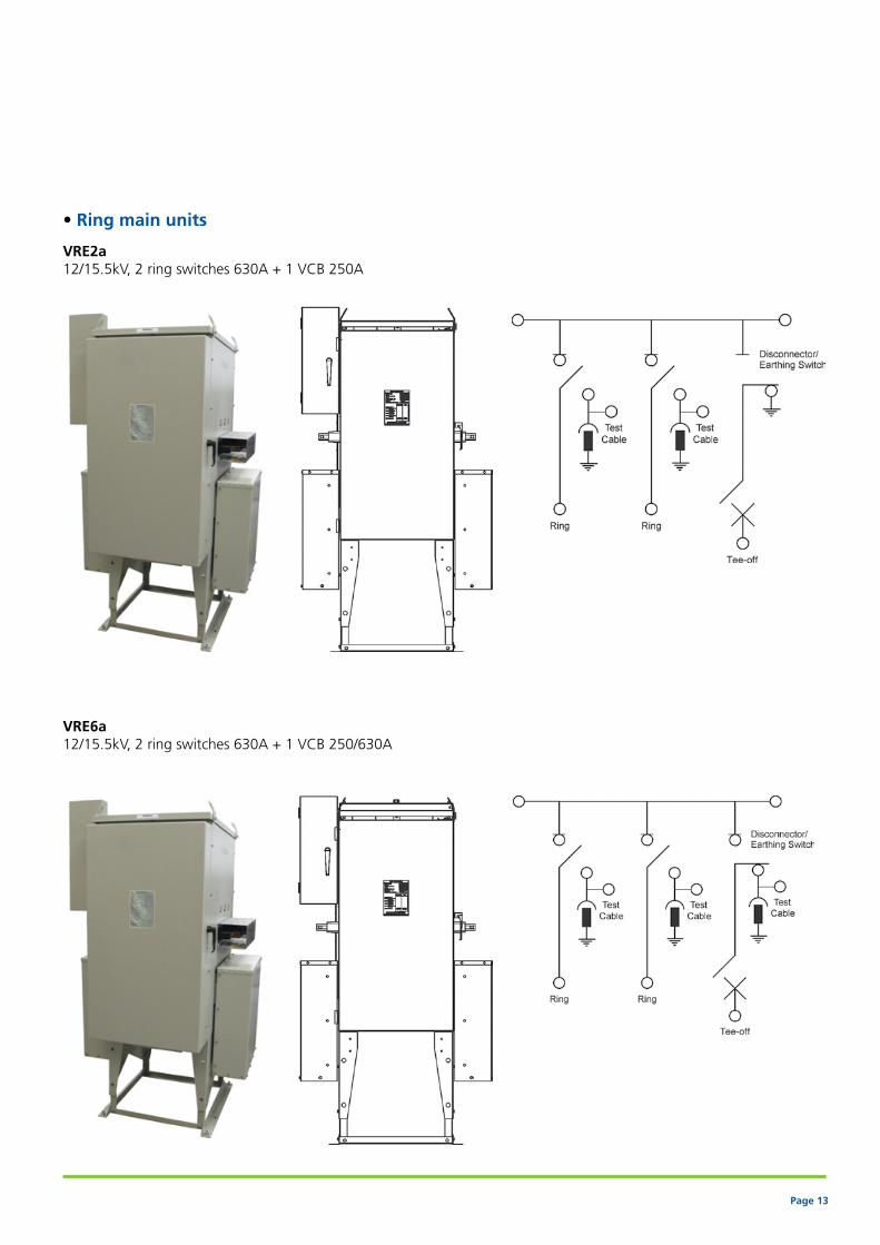
• Ring main units
VRE2a 12/15.5kV, 2 ring switches 630A + 1 VCB 250A
VRE6a 12/15.5kV, 2 ring switches 630A + 1 VCB 250/630A

Page 14
The Sabre range
DSE6a 12/15.5kV, 2 ring switches 630A
• Modular ring switch
SSE6a 12/15.5kV, 1 ring switch 630A

Page 15
VCE6a 12/15.5kV, 1 VCB 630A
• Modular circuit breakers
VCE2a 12/15.5kV, 1 VCB 250A

Page 16
Mounting style
• Freestanding units
Outdoor free standing with bottom entry cable box
Indoor free standing with top entry cable box

Page 17
• Transformer mounted unit
The Sabre ring main unit along with the low voltage distribution cabinet is mounted on the distribution transformer to form a low cost outdoor package substation to be used in distribution networks.
Page 18
Product characteristics
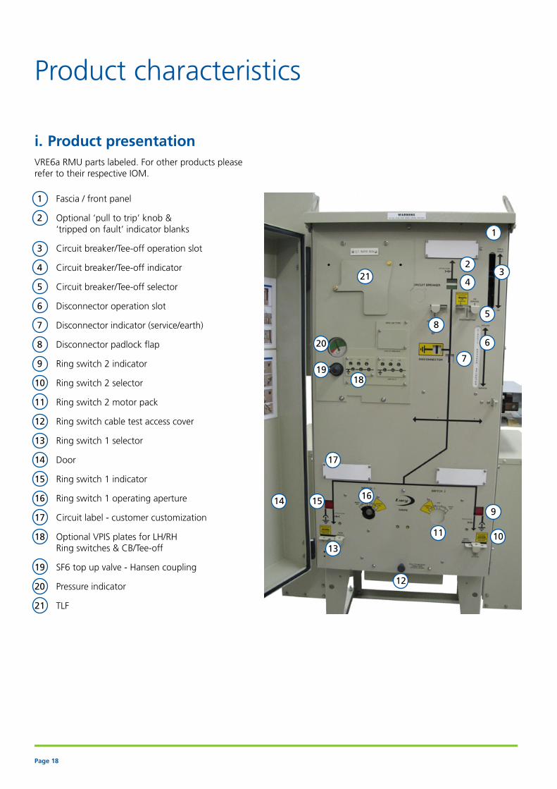
i. Product presentationVRE6a RMU parts labeled. For other products please refer to their respective IOM.
1 Fascia / front panel
2 Optional ‘pull to trip’ knob & ‘tripped on fault’ indicator blanks
3 Circuit breaker/Tee-off operation slot
4 Circuit breaker/Tee-off indicator
5 Circuit breaker/Tee-off selector
6 Disconnector operation slot
7 Disconnector indicator (service/earth)
8 Disconnector padlock flap
9 Ring switch 2 indicator
10 Ring switch 2 selector
11 Ring switch 2 motor pack
12 Ring switch cable test access cover
13 Ring switch 1 selector
14 Door
15 Ring switch 1 indicator
16 Ring switch 1 operating aperture
17 Circuit label - customer customization
18 Optional VPIS plates for LH/RH Ring switches & CB/Tee-off
19 SF6 top up valve - Hansen coupling
20 Pressure indicator
21 TLF
20
1918
17
1615
13
12
14
11 10
9
8
7
6
5
4
2
1
321

Page 19
ii. User interface and interlocking mechanismSafety interlocking Ring switch and circuit breaker mechanisms are fitted with safety interlocks to protect the operator and equipment from unintentional operation
Ring switch mechanism
Circuit breaker mechanism
Position Interlock status
Ring switch Selector Cable box(optional)
Earth & test interlock
ON Main ON Locked
OFF Main ON Locked
OFF Earth ON Locked
Earth ON Earth OFF Unlocked
Position Interlock status
Circuit breaker
Selector Cable compartment
interlock(optional)
Earth & test interlock (optional)
ON Main Locked Locked
OFF (Tripped) Main Locked Locked
OFF (Reset) Earth Locked Locked
Earth ON Earth Unlocked Unlocked
Earth ON Earth Locked Locked
OFF (Tripped) Earth Locked Locked

Page 20
iii. Ring switchStandard features• Three function ON, OFF & Earth spring loaded
mechanism, independent manual operation
• Single mechanism with rotary moving shaft for switching ON/OFF/Earth positions
• Interlocked selector with padlocking facility for selecting Mains or Earth ON position
• Single line intuitive mimic diagram with clear indication of switch status (ON, OFF or Earth position)
• Fully interlocked cable earth and test (E&T) facility
• Gas pressure indicator
• Lateral cable terminations with DIN 400 type C bushings
• Padlock facility (8.5mm diameter hole) for all the operating positions
Optional features, factory fitted• Remote low gas pressure alarm,1N/O
• VPIS - voltage presence indication system
• Remote switch position indicator (1N/O,1N/C and 2N/O, 2NC)
• Short circuit and earth fault current indicators (EFI)
• Actuator (motor) wiring
• Castell locks
Optional features also available as retrofit• Actuator (motor) for ring switch (only if unit is pre
wired for motorisation)
• Internal arc rated cable box
• Wide range of cable glands and accessories to accommodate 1 and 3 core cables (refer to cable box section for further information)
iv. Vacuum circuit breaker• 250A rated vacuum circuit breaker for
transformer protection
• 400A rated vacuum circuit breaker for transformer/downstream network protection
• 630A rated vacuum circuit breaker for transformer/downstream network protection
Standard features• Three functions (ON, OFF & Earth), two position spring
loaded mechanism, independent manual operation
• Single mechanism with two independent operating shafts, one for circuit breaker ON/OFF position and another for selecting disconnector in Mains or Earth (isolation)
• Interlocked disconnector selector, locked from operation when circuit breaker is in ON position
• Trip coil for receiving tripping signal from relay or TLF devices
• Protection function TLF or relay (customer specific)
• Single line intuitive mimic diagram with clear indication of switch status (ON, OFF or Earth position)
• Gas pressure indicator
• Horizontal cable terminations at the rear of the unit with parallel bushings (except for VRNFS and VRN24 which have DIN 400 type C bushings as standard)
• Protection CTs (current transformers) mounted on cable bushings (customer specific ratios)
• Padlock facility (8.5mm diameter hole) for all the operating positions
Optional features, factory fitted• Remote low gas pressure alarm,1N/O
• Mechanical (manual) pull-to-trip button for local operation
• VPIS (voltage presence indication system - refer to VPIS section for more details)
• Remote circuit breaker position indicator (1N/O,1N/C and 2N/O, 2NC)
• Fully interlocked cable earth and test facility (only on 630A VCB)
• Self-powered relay for protection (customer specific)
• TLF (time limit fuses) for alternative protection
• Wide range of CTs for TLF and relay protection
• Remote protection trip output status signal (for TLF or relay trip status) 1N/O
• Shunt trip coils for external tripping
• Tripped on fault indication
• Watchdog for relays (only available with selective relays)
• Circuit breaker actuator enabled indication
• Actuators (motor) wiring
Optional features also available as retrofit• Actuator (motor) for CB (only if unit is pre wired for
motorisation)
• Internal arc rated cable box
• Wide range of cable glands and accessories to accommodate 1 and 3 core cables (refer to cable box section for further information)

Page 21
v. Circuit breaker protection
Two types of protection devices are offered to protect the circuit breaker• TLF : Time limit fuses• Protection relays
a. TLF When utilised in conjunction with circuit breaker type ring main units, time limit fuses (TLF) are a cost effective method of providing fault protection for overcurrent and earth faults (optional) to a transformer of 2MVA or less.
It is a recognised method of protection and was developed to comply with EA 41-26 (now superseded by ENA TS 41-36) with fuse links in accordance with ENA TS 12-6.
It should be noted that the TLF protection system is not a device for limiting overload levels of individual transformers. It should be used for fault protection only.
The TLF system provides protection for overcurrent and earth faults between the MV circuit breaker and the LV protection device.
The selected TLF rating should be such that it allows for discrimination between the MV & LV devices. This will ensure that the circuit breaker does not open for faults beyond the LV distributor protection device.
When fitted with TLF, the Lucy RMU can also be configured to enable tripping of the circuit breaker from remote devices (Bukholtz, LV CB etc).
Lucy Switchgear customers in Europe, the Middle East, Africa and Asia are currently using TLF protection system within their distribution networks.
Fuse dimensions: Length 57mm x Diameter 13mm

Page 22
Recommended TLF settings
Advantage of vacuum circuit breaker with TLF compared to HV fuses
Advantage of vacuum circuit breaker with TLF compared to protection relays
Feature VCB with TLF Fuse switch
Overall cost of units Similar
Approximate fuse replacement cost $5 $50
Maximum rating of transformer, can be protected 2MVA* 1MVA
Maximum rated normal current 630A 200A
Physical size of fuses Small Large
Possibility of some pollution while changing fuses causing PD and flashover issues No Yes
Fuse location inside the unit LV side HV side
Range of fuses required for different rated transformers Very small with multi ratio CT Large
Feature TLF Protection relay
Installation cost of function Low High
Auxiliary power source for operation Not required As required
Delay in activation of trip function due to capacitor charging time lag No delay Delay
Employee training on setting tripping curves Not required Required
Additional training on different manufacturer setting up procedure Not required Required
Maintenance and repair cost Low High
Operating temperature limitations None Up to 70 °C
Upstream and downstream discrimination protection of circuit Yes Yes
Overcurrent and Earth fault protection Yes Yes
Transformer ratings (kVA)
200 315 500 800 1000 1250 1600 2000
Rated voltage (kV) TFL fuse rating (A)
ct ratio 50/5
Earth fault setting = 25A (instantaneous trip)
3.3 10A
6.6 5A 10A 15A
11 3A 5A 10A 15A
13.8 3A 5A 10A 15A
24 3A 5A 7.5A
ct ratio 100/5
Earth fault setting = 30A (instantaneous trip)
3.3 5A 10A 15A
6.6 5A 7.5A 12.5A 15A
11 5A 7.5A 10A 12.5A 15A 12.5A
13.8 5A 7.5A 10A 12.5A 15A
24 5A 5A 7.5A
(* No issues with transfer current switching to IEC 62271-105, which minimizes the MVA rating)

Page 23
b. Protection relays Woodward WIP 1
Manufacturer Woodward
Range WIP1
Functions
Phase overcurrent •
Short circuit protection •
Number of overcurrent elements 2
Earth overcurrent •
Number of earth overcurrent elements 2
Characteristics
Display (measuring values and parameters) •
Setting via buttons •
Standard CT (1A/5A) 1A
LED pickup •
LED trip indicator •
Flag indication output •
Fault memory •
Clock •
Password protection •
Electro impulse and relay contact output •
Number of output relays 3 C/O
Input remote tripping •
Interface O
RS 485 interface with pro open data protocol O
RS-485 interface with Modbus protocol O
Additional power supply O
The Sabre range can be fitted with self-powered relays for protecting the transformer or downstream network from fault currents by tripping the circuit breaker. These relays incorporate many advanced features and have a variety of settings to provide discrimination protection in networks. The self-powered feature eliminates reliance on external power sources and increases the performance and reliability of the protection function.
Below are the technical characteristics of Woodward WIP1 and Fanox SIAC range. Other manufacturers’ relays can also be incorporated into the units on request.
Key • Standard O Option

Page 24
Fanox
Manufacturer Fanox Fanox Fanox
Range SIAC*********D SIAC*********B SIAC*********FA
Functions
Phase overcurrent • • •
Short circuit protection • • •
Number of overcurrent elements 250P:
Tap:0.1…30xInTime:0,02…300 s
51P:Tap:0.1…7xIn
250P:
Tap:0.1…30xInTime:0,02…300 s
51P:Tap:0.1…7xIn
3(2) 50P:
Tap:0.1…30xInTime:0,02…300 s
51P:Tap:0.1…7xIn
Earth overcurrent • • •
Number of earth overcurrent elements
250N:
Tap:0.1…30xInTime:0,02…300 s
51N:Tap:0.1…7xIn
250N:
Tap:0.1…30xInTime:0,02…300 s
51N:Tap:0.1…7xIn
3(2) 50N:
Tap:0.1…30xInTime:0,02…300 s
51N:Tap:0.1…7xIn
Pickup level 0,2xIn(single phase)0,1xIn (three phase)
0,2xIn(single phase)0,1xIn (three phase)
0,2xIn(single phase)0,1xIn (three phase)
Startup time (Trip time after fault. Single phase)
130 ms 130 ms 70 ms
Characteristics
Display (measuring values and parameters)
• (Display 20x2)
• (Display 20x2)
• (Display 20x2)
Setting via buttons • • •
Test menu • The test menu can be used to
check the operation of the signaling components (LEDs and magnetic indicators), along with the trip output and the signaling
outputs
• The test menu can be used to
check the operation of the signaling components (LEDs and magnetic indicators), along with the trip output and the signaling
outputs
• The test menu can be used
to check the operation of the signaling components (LEDs and magnetic indicators), along with the trip output and the signaling
outputs
Settings groups 1 1 3
Standard CT (1A/5A) 1A or 5A (depending on model) 1A or 5A (depending on model) 1A or 5A (depending on model)
LED pickup The pickup message is shown at the display. Besides, the SIA-C front panel has three LED pilot
lights to show the type of power being used: self-power, battery or
auxiliary power
The pickup message is shown at the display. Besides, the SIA-C front panel has three LED pilot
lights to show the type of power being used: self-power, battery or
auxiliary power
The pickup message is shown at the display. Besides, the SIA-C front panel has two LED pilot
lights to show the type of power being used: self-power or battery
LED trip indicator To signal the trip, the front panel is equipped with 1 bistable magnetic
indicator which indicates a trip has occurred
To signal the trip, the front panel is equipped with 1 bistable magnetic
indicator which indicates a trip has occurred
To signal the trip, the front panel is equipped with 2 bistable magnetic
indicators which indicates a trip has occurred
Page 25
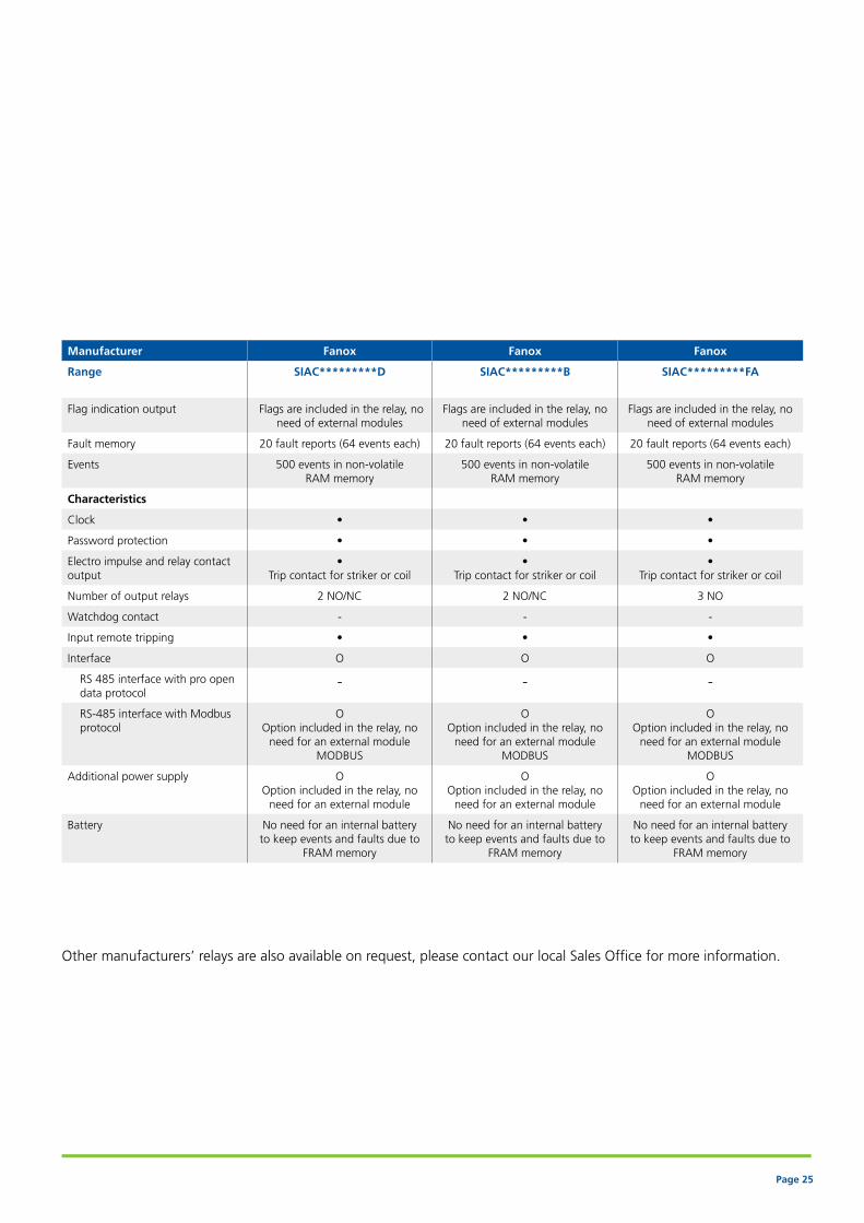
Manufacturer Fanox Fanox Fanox
Range SIAC*********D SIAC*********B SIAC*********FA
Flag indication output Flags are included in the relay, no need of external modules
Flags are included in the relay, no need of external modules
Flags are included in the relay, no need of external modules
Fault memory 20 fault reports (64 events each) 20 fault reports (64 events each) 20 fault reports (64 events each)
Events 500 events in non-volatile RAM memory
500 events in non-volatile RAM memory
500 events in non-volatile RAM memory
Characteristics
Clock • • •
Password protection • • •
Electro impulse and relay contact output
• Trip contact for striker or coil
• Trip contact for striker or coil
• Trip contact for striker or coil
Number of output relays 2 NO/NC 2 NO/NC 3 NO
Watchdog contact - - -
Input remote tripping • • •
Interface O O O
RS 485 interface with pro open data protocol
- - -
RS-485 interface with Modbus protocol
O Option included in the relay, no
need for an external moduleMODBUS
O Option included in the relay, no
need for an external moduleMODBUS
O Option included in the relay, no
need for an external moduleMODBUS
Additional power supply O Option included in the relay, no
need for an external module
O Option included in the relay, no
need for an external module
O Option included in the relay, no
need for an external module
Battery No need for an internal battery to keep events and faults due to
FRAM memory
No need for an internal battery to keep events and faults due to
FRAM memory
No need for an internal battery to keep events and faults due to
FRAM memory
Other manufacturers’ relays are also available on request, please contact our local Sales Office for more information.
Page 26
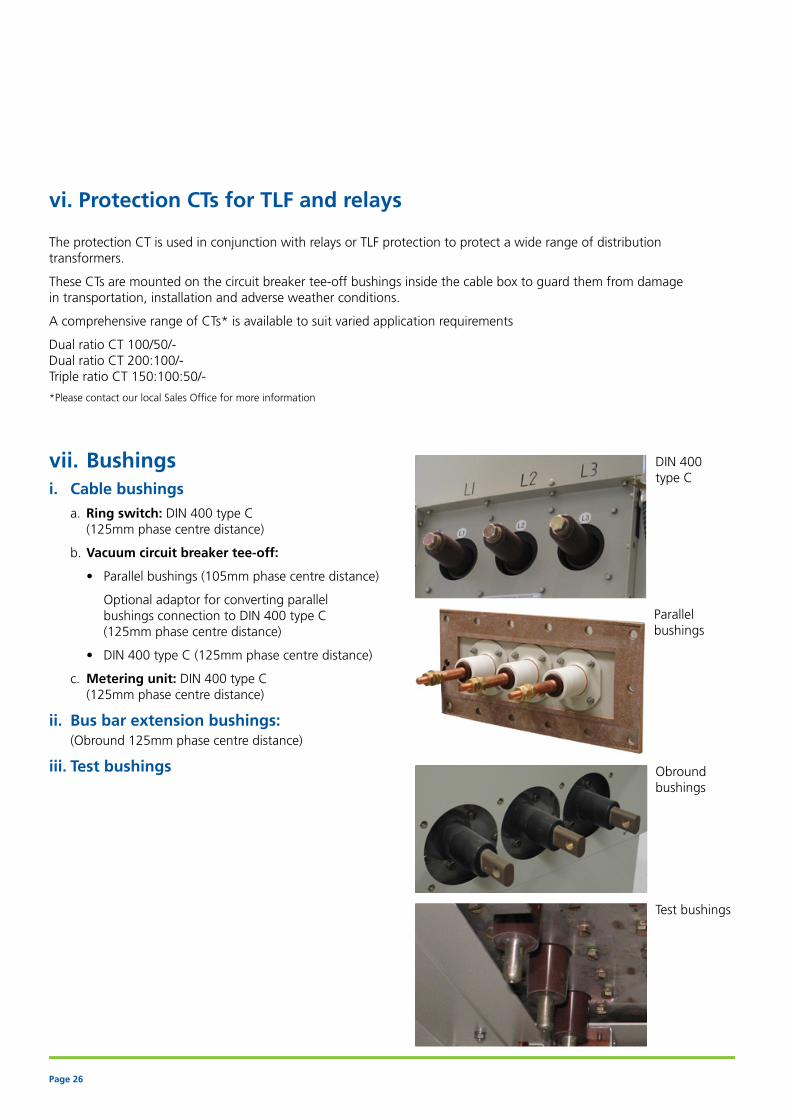
vii. Bushingsi. Cable bushings
a. Ring switch: DIN 400 type C (125mm phase centre distance)
b. Vacuum circuit breaker tee-off:
• Parallel bushings (105mm phase centre distance)
Optional adaptor for converting parallel bushings connection to DIN 400 type C (125mm phase centre distance)
• DIN 400 type C (125mm phase centre distance)
c. Metering unit: DIN 400 type C (125mm phase centre distance)
ii. Bus bar extension bushings: (Obround 125mm phase centre distance)
iii. Test bushings Obround bushings
Parallel bushings
DIN 400 type C
Test bushings
vi. Protection CTs for TLF and relays
The protection CT is used in conjunction with relays or TLF protection to protect a wide range of distribution transformers.
These CTs are mounted on the circuit breaker tee-off bushings inside the cable box to guard them from damage in transportation, installation and adverse weather conditions.
A comprehensive range of CTs* is available to suit varied application requirements
Dual ratio CT 100/50/- Dual ratio CT 200:100/- Triple ratio CT 150:100:50/-
*Please contact our local Sales Office for more information

Page 27
Vaccum circuit breaker actuator
Ring switch actuator
Marshalling box
Options and accessories
i. Secondary injection
Secondary injection is used to test the relays or TLF operation without switching on the high voltage supply to the unit. A low voltage is applied to the secondary side of the CT connection (located in terminal box) to test the operation of the protection devices at the time of commissioning and routine tests.
ii. Actuators (motors)
Sabre units are fitted with 24V DC motors, which can be powered from the Gemini remote terminal unit (RTU) 24V DC battery in the event of mains AC supply failure.

Page 28
iii. Cable boxes, glands and accessories
Cable boxCable boxes are available for the following: o Ring switches cable bushings o Circuit breakers tee-off bushings o Metering units bushings o Extensible bus bar bushings• Safety interlocks: The cable boxes can be interlocked with a ring
switch or circuit breaker mechanism. Interlocked cable boxes can only be removed when the circuit is in the ‘Earth ON’ position
• Internal arc rating o Non internal arc rated cable box as standard o Internal arc rated cable boxes 12.5kA 1sec and 20kA
1 sec as optional• Cable box lengths o 450mm o 610mm• Cable entry o Top entry with • IP50 standard (indoor only) • IP54 optional o Bottom entry with IP54 as standard • Straight • Angled
Cable gland and gland plates• Cable gland and gland plates o 1 x 3 core cable • X size • Gland plates o X size gland plate with earth stud o X size gland plate with earth bar • Glands o X tube glands o X brass wiping gland • Y size • Gland plates o Y size gland with earth stud o Y size gland with earth bar • Glands o Y tube glands o Y brass wiping gland o 3 x 1 core cable • Gland plates • 3 hole split steel with earth stud • 3 hole split steel with earth bar • 3 hole solid brass with earth stud • 3 hole solid brass with earth bar • Glands • Single core compression gland • Single core heat shrink glands
Bottom entry
Top entry cable box
Angled cable box
For further information refer to the accessories table.

Page 29
iv. Bus bar couplingsBus bar couplings are used to connect two extensible units.
Bus bar coupling lengths • 378mm• 453mm• 500mm• 750mm
Bus bar insulation types• Heat shrink (manufactured by SPS)• Heat shrink (manufactured by Raychem)• Heat shrink (manufactured by REPL)• Cold fit rubber boot (manufactured by Pirelli)
v. MV sensorsMV sensors are used to detect the medium voltage in the cable and send a signal to the remote control device for auto changeover.
vi. Watchdog for relaysThey are used to check the healthy operation of relays.
vii. Operation counterThey are used to count the number of mechanical operations of the ring switch and circuit breaker mechanisms.
viii. Castell locksRing switch: Castell locks are used to prevent closing of the open point in the ring network.
Circuit breaker: Key free Earth ON: They are typically used for preventing transformer cubicle access until the circuit breaker is in the Earth ON position.
ix. Protection trip remote indicatorThey are used to send a signal to a remote terminal unit if a protection device relay or TLF has tripped (operated).
Castell lock

Page 30
x. Shunt trip coilsShunt trips are magnetic coils that are used to trip circuit breakers through local push buttons, RTUs or additional transformer protection devices.
Shunt trips are available in the following voltages:
• DC voltage: 12V, 24V, 48V and 110V• AC voltages: 110V, 240V• Multiple voltage range: 24VAC/DC – 240VAC/DC.
xi. Earth Fault Indicators (EFI)Earth fault indicators (EFI) are used for rapid location and isolation of faults on medium voltage networks in open loop ring main networks. When the unit detects asymmetrical currents in the 3 phase cable, an earth fault is indicated by means of a flashing LED or mechanical flag.
Below is the list of EFIs available for the Sabre range
Key • Standard O Option Other manufacturers’ EFIs are also available on request, please contact our local sales office for more information.
Shunt trip
Manufacturer Model: BLZ-50 BFZ-50 MFZ-50 MLZ-50 CFZ-50 CLZ-50
Suparule Sensorform
Features
Power source 3.6V lithium ½ AA 850mAH battery
110-240V a.c. CT on current carrying phase
Voltage range 1 – 38kV
Trip current 50A
Primary indication LED Mech-flag (RED) LED Mech-flag (RED) LED
Flashing duration >1000 hrs - - 10 hrs - 10 hrs
Minimum fault duration 2.5 cycles
Manual reset Push button
Automatic timer reset 4 or 8 hrs selectable 10 secs after mains restore
Manual trip test Push button
Operating temperature -40°C to +80°C
Operating humidity 0-100% RH
Ingress protection IP65
Current sensor diameter: CT100: 100mm • • • • • •
CT150: 150mm O O O O O O
CT300: 300mm O O O O O O
Remote flashing LED indicator O O O O O O
Auxiliary relay, 1N/O latching O O O O O O

Page 31
Cable terminations
The bushings are accessible by removing the cable box covers at the lateral and rear of the unit.
The maximum cable sizes that can be used are:• 300mm² 3 - core• 500mm² single - core.The following types of terminations can be used with the Sabre range:
DIN type C bushings (cable boxes)• Insulating bushing boot• Heat shrink insulating bushing boot• Profile “C” bolted separable
Obround bushings (bus bar extension)The following cable connections could be used if direct cable connection is required on the bus bar bushings• Insulating bushing boot• Heat shrink insulating bushing boot
Parallel bushings (tee-off)The following connectors could be used if cable tee-off direct cable connection is required• Insulating bushing boot• Heat shrink insulating bushing boot
Insulating bushing boot Heat shrinkinsulating bushing boot
Profile “C” bolted separable

Page 32
Air metering unit (AMU)
i. Characteristics• Up to 17.5kV and 630Amps ratings• Freestanding and RMU mounted version• Voltage transformer (VT) isolation for HV testing• Bus bar metering and tee-off metering options• Trip lock out relay for RMU/AMU combinations for
emergency tripping• Wide range of CT and VT options to suit various
application needs• IP54 for outdoor installation without needing a kiosk
ii. Mounting stylea. Tee-off meteringb. BC: Bus bar connectedc. FS: Free standing metering
Tee-off metering RMU mounted
Free standing metering unit
Free standing meteringBus bars connected metering
Tee-off metering

Page 33
Remote terminal unit (RTU)
The Gemini RTU is an advanced, highly flexible and ultra-efficient solution for remote operation and control of electrical distribution networks. Enclosed in a stainless steel casing for maximum protection, the Gemini RTU is designed to operate in the most demanding environments.
The key features of the Gemini range are:
• Embedded auto change over and auto sectionalizing functions
• Control and monitoring of up to 4 motorized functions (switches or circuit breakers)
• Inbuilt earth and fault passage indicators• Advanced monitoring of current, voltage, battery
condition, switching parameters such as open/close status, actuator disabled and gas pressure
• Flexible communication through radio, RS232, packet data network, GSM, GPRS, PSTN, bluetooth, ethernet TCP/IP, optical fibre and SMS messaging
• Advanced battery pack to operate under mains AC input failure
• Fully tested to ENATS (Energy Network Association Technical Standards), EMC and environmental standards
In addition to the above features, remotely monitored and controlled switchgear provides significant benefits to customers such as:
• Reduced time in diagnosing system anomalies as well as locating and isolating faulty sections of the network
• Faster response time and quick network reconfiguration• Optimisation of asset management through the
implementation of customized automation schemes• Reduced operational cost associated with routine
network switching• Increased operator safety
RTU enclosure

Page 34
Gemini RTU SpecificationGeneral Enclosure Stainless steel
Degree of protection IP54
Operating temperature -25 to 60C
Relative humidity Up to 95%
Method of mounting Floor, wall, pole or RMU switchgear
Dimensions H 600mm, W 400mm, D 210mm
RTU hardware Processor module ARM9 microprocessor
Power supply 110/230V AC supply - over and under-voltage protection
Battery type 2 x 12V DC, sealed lead acid or high temperature NiMH
Battery charger Temperature compensated, fully protected
Control electronics PIC based processor with expandable I2C bus
Inner enclosure Stainless steel
Ventilation Microprocessor controlled, long life fan with baffle air intake filter
Inputs / Outputs Digital inputs 14 isolated digital inputs - expandable
Digital outputs 8 isolated digital outputs - expandable
Analogue inputs 3 CT analogue inputs as standard (DIs reduced to 11)
Expansion I/O module 3 AIs / 4 DIs; 7 DIs / 2 DOs
Communications Communication interfaces3 RS-232 for control (ethernet option), configuration and programming plus one expansion bus
ProtocolsDNP3, IEC 60870-5-101/104 and Modbus (others on request)
Communication media
RS-232, UHF / VHF radio, packet data, GSM / GPRS / EDGE, PTSN, leased or twisted pair lines, optical fibre, ethernet (TCP/IP) and bluetooth
Switchgear interface Controls
Membrane push-button for open / close operations in conjunction with activate push-button, up to four switching functions (standard 1, 2, 3 or 4 switch control formats),selector control for off, local or remote modes
Indications
RTU services such as DC / AC supplies, dummy control and debug LEDsSwitch status LEDs for open / closed positionsControl output LEDs (illuminates when active)Configurable LED indications
Cables Plug-in, multi-core umbilicals to switchgear
Software Configuration
Windows-based software for configuration of:• Protocol parameters including device and I/O addresses• Parameters for the communications device• Parameters for digital, analogue and counter points• Automation sequences• Power saving routines• Battery tests
Gemini RTU Specification

Page 35
Technical Data Sheet
Ring main unit Modular circuit breaker
Modular ring switch
Non Extensible Extensible NonExtensible
Models VRN2a VRN6a VRNFS VRN24 VRE2a VRE6a VCE2a VCE6a SSE6a DSE6a DSN6a
Description 2 RSW+ 1VCB
2 RSW+ 1VCB
2 RSW+ 1VCB
2 RSW+ 1VCB
2 RSW+ 1VCB
2 RSW+ 1VCB 1 VCB 1 VCB 1 RSW 2 RSW 2 RSW
GeneralRated voltage kV 12 (15.5) 12 (15.5) 17.5 24 12 (15.5) 12 (15.5) 12 (15.5) 12 (15.5) 12 (15.5) 12 (15.5) 12 (15.5)
Rated frequency Hz 50/60
Rated lightning impulse withstand voltage
Directly earthed kV 75 (95) 95 125 75 (95)
Across disconnector kV 85 (110) 110 145 85 (110)
Rated power frequency withstand voltage
Directly earthed kV 28 (38) 38 50 28 (38)
Across disconnector kV 38 (45) 45 60 38 (45)
Protection
Overall unit IP IP54
Tank with HV parts IP IP67
LV control box IP IP54
Front face + mechanism IP IP2x
Cable box IP IP54
Mechanical impact protection IK IK07 (2J) Indoor, IK08 (5J) Outdoor
Internal arc protection
Unit kA 1 sec 20 21 16 20
cable box (optional) kA 1 sec 12.5/20 21 12.5 12.5/20
Gas tank internal arc ratings
AF Standard
AFL Optional
AFLR - Optional - - Optional
SF6 gas
Filled pressure Bar (G) 0.4 0.5 0.4
Minimum operating presure Bar (G) 0 0.3 0
Annual leakage rate ≤0.1% per annum
Weight Kg 1.46 1.56 1.78 1.05 0.78 0.98
Installation conditions
Ambient air temperature ˚C 40 / 50
Maximum altitude (without derating)* M 1000
Relative humidity (max) - over period of 24hrs (IEC 62271-1, sub-clause 2.1)
100%
Ring main unit Modular circuit breaker
Modular ring switch
Non Extensible Extensible NonExtensible
Models VRN2a VRN6a VRNFS VRN24 VRE2a VRE6a VCE2a VCE6a SSE6a DSE6a DSN6a
Description 2 RSW+ 1VCB
2 RSW+ 1VCB
2 RSW+ 1VCB
2 RSW+ 1VCB
2 RSW+ 1VCB
2 RSW+ 1VCB 1 VCB 1 VCB 1 RSW 2 RSW 2 RSW
Bus barsRated normal current A 630 400/630 630
Rated short time withstand current 20 kA 3s 21kA 1s 16kA 3s 20kA 3s
Rated peak withstand current kA 50 54.6 40 50
* for higher altitude applications please contact our local Lucy Switchgear sales office

Page 36
Ring main unit Modular circuit breaker
Modular ring switch
Non Extensible Extensible NonExtensible
Models VRN2a VRN6a VRNFS VRN24 VRE2a VRE6a VCE2a VCE6a SSE6a DSE6a DSN6a
Description 2 RSW+ 1VCB
2 RSW+ 1VCB
2 RSW+ 1VCB
2 RSW+ 1VCB
2 RSW+ 1VCB
2 RSW+ 1VCB 1 VCB 1 VCB 1 RSW 2 RSW 2 RSW
Ring switchRated normal current A 630 400/630 630 630 630
Rated active load breaking current A 630 400/630 630 630 630
Rated short circuit making current
Ring switch kA 50 54.6 40 50 50
Earth switch kA 50 54.6 40 50 50
Rated cable charging breaking current A 25 25
Rated short time withstand current
Ring switch 20 kA 3s 21kA 1s 16kA 3s 20kA 3s 20kA 3s
Earth switch 20 kA 3s 21kA 1s 16kA 3s 20kA 3s 20kA 3s
Mechanical endurance class
Ring switch M2 (5000) M2 (5000)
Earth switch M1 (1000) M1 (1000)
Electrical endurance class short circuit making
Ring switch E3 (5 times) E1 (2 times) E3 (5 times) E3 (5 times)
Earth switch E2 (3 times) E1 (2 times) E2 (3 times) E2 (3 times)
Operating mechanism
Local: close/open Handle Handle
Remote: close/open Actuator (Motor) Actuator (Motor)
Ring main unit Modular circuit breaker
Modular ring switch
Non Extensible Extensible NonExtensible
Models VRN2a VRN6a VRNFS VRN24 VRE2a VRE6a VCE2a VCE6a SSE6a DSE6a DSN6a
Description 2 RSW+ 1VCB
2 RSW+ 1VCB
2 RSW+ 1VCB
2 RSW+ 1VCB
2 RSW+ 1VCB
2 RSW+ 1VCB 1 VCB 1 VCB 1 RSW 2 RSW 2 RSW
Vacuum circuit breakerRated normal current A 250 630 400 400 250 630 250 630
Rated active load breaking current A 250 630 400 400 250 630 250 630
Rated short circuit breaking current kA 20 21 16 20
Rated short circuit making current
Circuit breaker kA 50 54.6 40 50
Earth switch kA 7.9 50 54.6 40 7.9 50 50 50
Rated cable charging breaking current A 25
Rated short time withstand current
Main electrical circuit 20 kA 3s 21kA 1s 16kA 3s 20kA 3s
Earthing circuit 3.15kA 3s 20kA 3s 21kA 1s 16kA 3s 3.15kA 3s 20kA 3s 3.15kA 3s 20kA 3s
Mechanical endurance class
Circuit breaker M1 (2000)
Earth switch M1 (1000)
Electrical endurance class
Circuit breaker E2
Earth switch E2
Operating mechanism
Tripping time ms <80ms
Operating sequence for mechanism 0-3min-CO-3min-CO
Local: close/open Handle
Remote: close/open Actuator (Motor)

Page 37
Dimensions
Dimensions & floor: VRN2A
Dim A(Ring bushingheight in mm)
Dim B(450mm Tail length cable box in mm)
Dim B(570mm Tail length cable box in mm)
Dim C
(mm)
Dim D
(mm)
Dim E(Tee-off bushingheight in mm)
1052 600 480 1715 817 1402
970 518 398 1633 735 1320
750 298 178 1413 515 1100
NOTE: All dimensions are in mm
Page 38
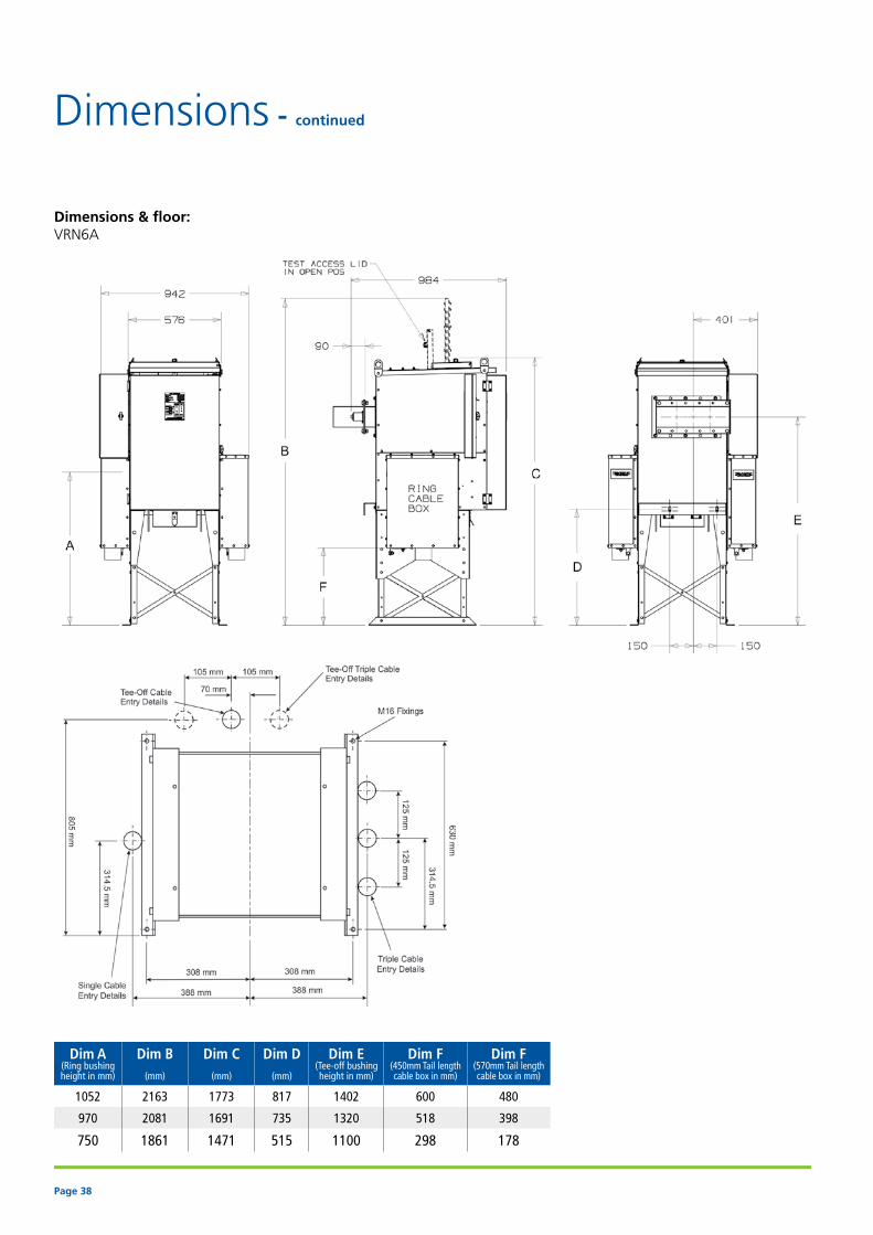
Dimensions & floor: VRN6A
Dim A(Ring bushingheight in mm)
Dim B
(mm)
Dim C
(mm)
Dim D
(mm)
Dim E(Tee-off bushingheight in mm)
Dim F(450mm Tail length cable box in mm)
Dim F(570mm Tail length cable box in mm)
1052 2163 1773 817 1402 600 480
970 2081 1691 735 1320 518 398
750 1861 1471 515 1100 298 178
Dimensions - continued

Page 39
Dimensions & floor: VRNFS
NOTE: All dimensions are in mm

Page 40
Dimensions - continued
Dimensions & floor: VRN24

Page 41
Dimensions & floor: DSN6A
NOTE: All dimensions are in mm

Page 42
Dimensions - continued
Dimensions & floor: VRE2A / VRE6A
Page 43
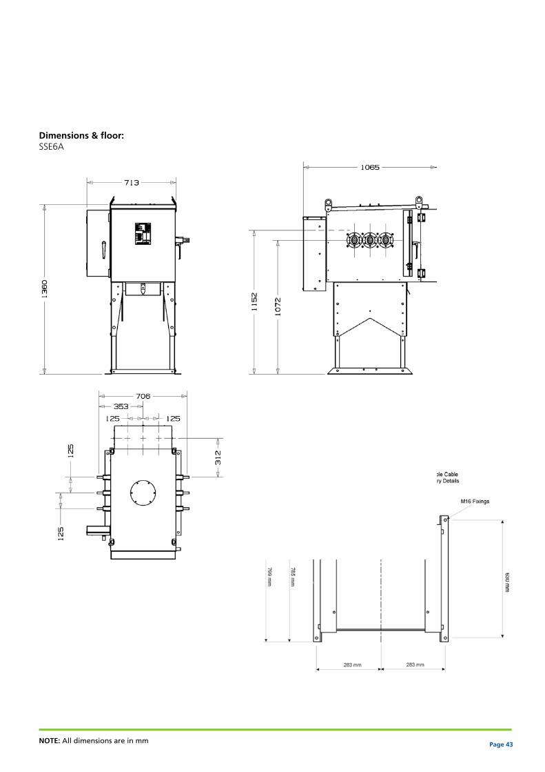
Dimensions & floor: SSE6A
NOTE: All dimensions are in mm

Page 44
Dimensions - continued
Dimensions & floor: DSE6A

Page 45
Dimensions & floor: VCE2A / VCE6A
NOTE: All dimensions are in mm

Page 46
Dimensions - continued
Dimensions & floor: AMU Free standing
Page 47
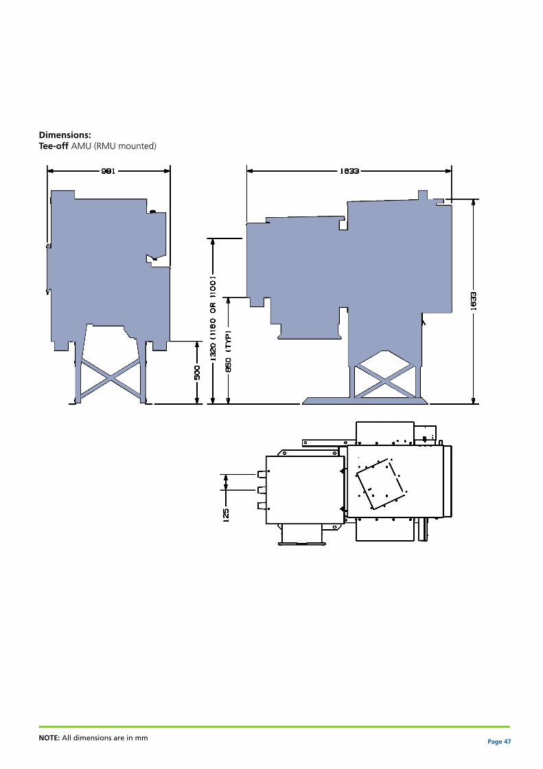
Dimensions: Tee-off AMU (RMU mounted)
NOTE: All dimensions are in mm

Page 48
Ring main units
Modular unitsRange Modular
circuit breaker
Modular ring switches
Extensibility Non extensible Extensible ExtensibleNon
extensible
Models VRN2a VRN6a VRNFS VRN24 VRE2a VRE6a VCE2a VCE6a SSE6a DSE6a DSN6a
Description 2 RSW+ 1VCB
2 RSW+ 1VCB
2 RSW+ 1VCB
2 RSW+ 1VCB
2 RSW+ 1VCB
2 RSW+ 1VCB 1VCB 1VCB 1 RSW 2 RSW 2 RSW
General ExtensibilityNon extensible • • • • - - - - - - •LH extensible - - - - o o o o o o -RH extensible - - - - o o o o o o -Both sides extensible - - - - o o o o o o -Impulse withstand voltage (BIL) kVP (choose one from below)
12kV at 75KVP BIL o o - - o o o o o o o15.5kV at 95KVP BIL o o - - o o o o o o o17.5kV at 95KVP BIL - - o - - - - - - - -24kV at 125kVP BIL - - - o - - - - - - -24kV at 145kVP BIL - - - o - - - - - - -Low gas pressure alarm auxiliary contact 1NO o o o o o o o o o o oPressure indicator gauge with Hanson coupling • • • • • • • • • • •Mounting styleTransformer mounted unit (fitted with ESI flange) o - - - - - o - - - -Freestanding unit o • • • • • o • • • •No ESI flange (with cable box)1 o o o o o o o o - - -ESI Transformer flange fitted (with/without cable box)1 o o o o o o o o - - -Height of tee-off bushing from floor (applicable to freestanding units)
1100mm o - - o - - - - - - -1320mm o o - o - - - - - - -1348mm - - • - - - - - - - -1402mm o o - o - - - - - - -Height of extension bushings from floor (applicable to free standing units)
1072 mm - - - - • • • • • • •Any other (available on request) - - - - o o o o o o oInternal arc protection for gas chamber (tank)AF • • • • • • • • • • •AFL o o o o o o o o o o oAFLR o o - o o o o o o o oTank exhaust at top • • - - • • • • • • •Tank exhaust at rear - - • • - - - - - - -Extensible bus bar bushings: Obround (Hysol) - - - - • • • • • • -Vacuum circuit breakerShort circuit breaking current16kA RMS - - - • - - - - - - -20kA RMS • • - - • • • • - - -21kA RMS - - • - - - - - - - -25KA RMS 2 - o o - - o - o - - -
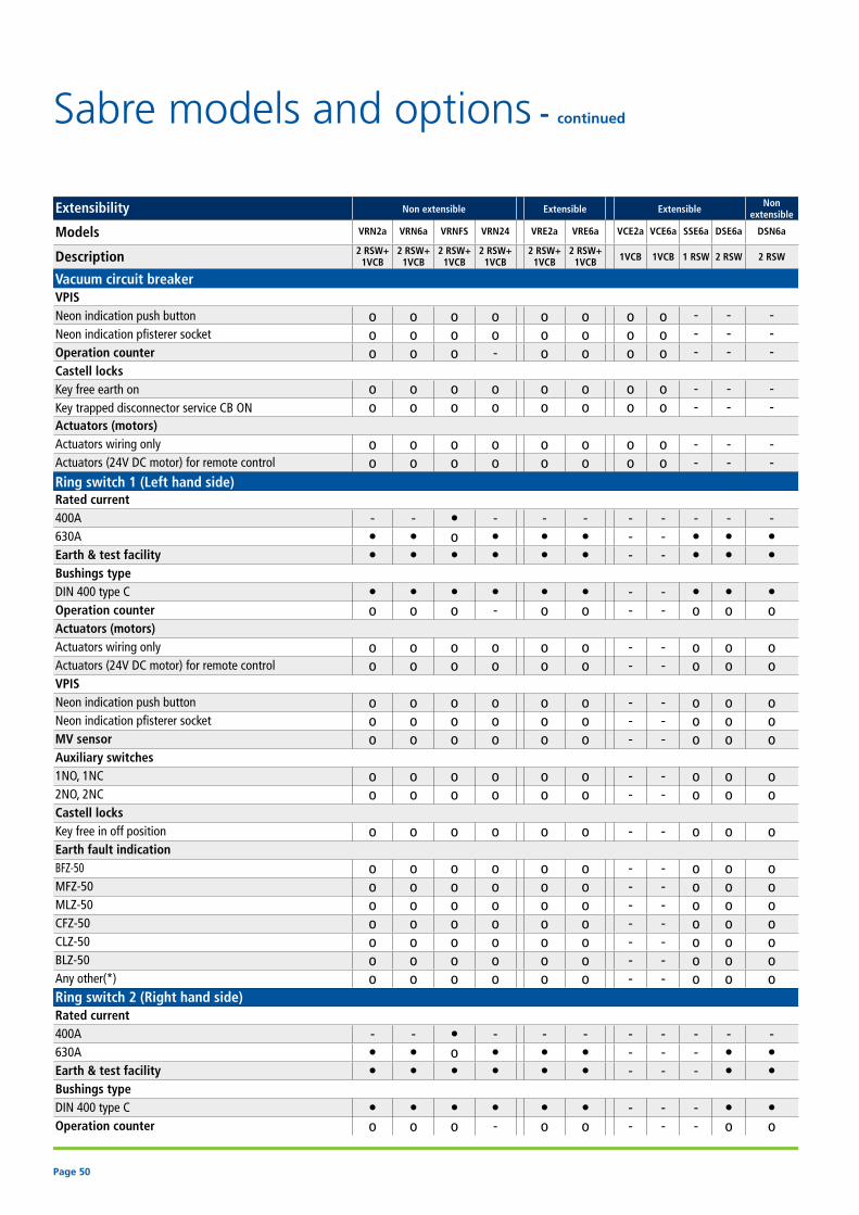
Sabre models and options

Page 49
Extensibility Non extensible Extensible ExtensibleNon
extensible
Models VRN2a VRN6a VRNFS VRN24 VRE2a VRE6a VCE2a VCE6a SSE6a DSE6a DSN6a
Description 2 RSW+ 1VCB
2 RSW+ 1VCB
2 RSW+ 1VCB
2 RSW+ 1VCB
2 RSW+ 1VCB
2 RSW+ 1VCB 1VCB 1VCB 1 RSW 2 RSW 2 RSW
Vacuum circuit breakerBushings typeParallel bushings • • - - • • • • - - -Adaptor to convert parallel bushings to DIN 400 type C bushing o o - - o o o o - - -DIN 400 type C - - • • - - - - - - -Rated normal current250A • o - - • o • - - - -400A - - • • - - - - - - -630A - • o - - • - • - - -Earth & test facility - o - - - o - o - - -Circuit breaker protectionTLF o o - o o o o o - - -Relay (choose one from below) WIP1 relay o o o o o o o o - - - Fanox relay o o o o o o o o - - - Any other* o o o o o o o o - - -Protection (CT) current transformersDual (Primary) ratio CT 100/50/- o o o o o o o o - - -Dual (Primary) ratio CT 200/100/- o o o o o o o o - - -Triple (Primary) ratio CT 150/100/50/- o o o o o o o o - - -Dual (Primary) ratio CT 400/200/- - o o o - o - o - - -Dual (Primary) ratio CT 150/100/- o o o o o o o o - - -Dual (Primary) ratio CT 600/200/- - o o - - o - o - - -Manual "Pull to trip" o o • • o o o o - - -Remote shunt trip12V DC o o o o o o o o - - -24V DC o o o o o o o o - - -48V DC o o o o o o o o - - -110V DC o o o o o o o o - - -110V AC o o o o o o o o - - -240V AC o o o o o o o o - - -Multi voltage (24V AC/DC- 240V AC/DC) o o o o o o o o - - -Indication / auxiliary switchesRemote protection trip output signal (for TLF or relay trip status) 1N/O o o o o o o o o - - -Watchdog for relays (only available with selective relays) o o o o o o o o - - -Tripped on fault indication o o o o o o o o - - -Circuit breaker actuator enabled indication o o o o o o o o - - -Circuit breaker service indication1NO, 1NC o o o o o o o o - - -2NO, 2NC o o o o o o o o - - -Circuit breaker earth indication1NO, 1NC o o o o o o o o - - -2NO, 2NC o o o o o o o o - - -Secondary injection terminals o o o o o o o o - - -Key • Standard 1: Refer to cable box, cable gland and gland plate table for more information o Options 2: Available soon - Not applicable
Page 50
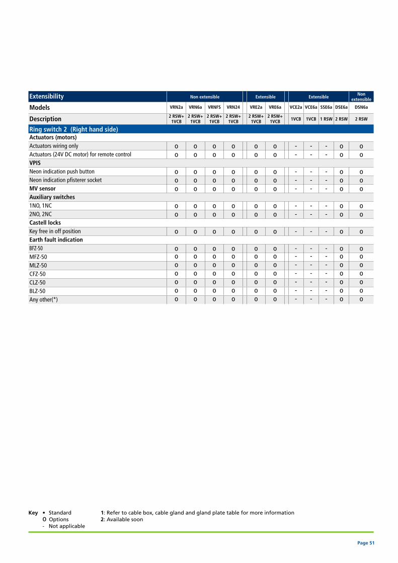
Sabre models and options - continued
Extensibility Non extensible Extensible ExtensibleNon
extensible
Models VRN2a VRN6a VRNFS VRN24 VRE2a VRE6a VCE2a VCE6a SSE6a DSE6a DSN6a
Description 2 RSW+ 1VCB
2 RSW+ 1VCB
2 RSW+ 1VCB
2 RSW+ 1VCB
2 RSW+ 1VCB
2 RSW+ 1VCB 1VCB 1VCB 1 RSW 2 RSW 2 RSW
Vacuum circuit breakerVPISNeon indication push button o o o o o o o o - - -Neon indication pfisterer socket o o o o o o o o - - -Operation counter o o o - o o o o - - -Castell locksKey free earth on o o o o o o o o - - -Key trapped disconnector service CB ON o o o o o o o o - - -Actuators (motors)Actuators wiring only o o o o o o o o - - -Actuators (24V DC motor) for remote control o o o o o o o o - - -Ring switch 1 (Left hand side)Rated current 400A - - • - - - - - - - -630A • • o • • • - - • • •Earth & test facility • • • • • • - - • • •Bushings typeDIN 400 type C • • • • • • - - • • •Operation counter o o o - o o - - o o oActuators (motors)Actuators wiring only o o o o o o - - o o oActuators (24V DC motor) for remote control o o o o o o - - o o oVPISNeon indication push button o o o o o o - - o o oNeon indication pfisterer socket o o o o o o - - o o oMV sensor o o o o o o - - o o oAuxiliary switches1NO, 1NC o o o o o o - - o o o2NO, 2NC o o o o o o - - o o oCastell locksKey free in off position o o o o o o - - o o oEarth fault indicationBFZ-50 o o o o o o - - o o oMFZ-50 o o o o o o - - o o oMLZ-50 o o o o o o - - o o oCFZ-50 o o o o o o - - o o oCLZ-50 o o o o o o - - o o oBLZ-50 o o o o o o - - o o oAny other(*) o o o o o o - - o o oRing switch 2 (Right hand side)Rated current400A - - • - - - - - - - -630A • • o • • • - - - • •Earth & test facility • • • • • • - - - • •Bushings typeDIN 400 type C • • • • • • - - - • •Operation counter o o o - o o - - - o o
Page 51
Extensibility Non extensible Extensible ExtensibleNon
extensible
Models VRN2a VRN6a VRNFS VRN24 VRE2a VRE6a VCE2a VCE6a SSE6a DSE6a DSN6a
Description 2 RSW+ 1VCB
2 RSW+ 1VCB
2 RSW+ 1VCB
2 RSW+ 1VCB
2 RSW+ 1VCB
2 RSW+ 1VCB 1VCB 1VCB 1 RSW 2 RSW 2 RSW
Ring switch 2 (Right hand side)Actuators (motors)Actuators wiring only o o o o o o - - - o oActuators (24V DC motor) for remote control o o o o o o - - - o oVPISNeon indication push button o o o o o o - - - o oNeon indication pfisterer socket o o o o o o - - - o oMV sensor o o o o o o - - - o oAuxiliary switches1NO, 1NC o o o o o o - - - o o2NO, 2NC o o o o o o - - - o oCastell locksKey free in off position o o o o o o - - - o oEarth fault indicationBFZ-50 o o o o o o - - - o oMFZ-50 o o o o o o - - - o oMLZ-50 o o o o o o - - - o oCFZ-50 o o o o o o - - - o oCLZ-50 o o o o o o - - - o oBLZ-50 o o o o o o - - - o oAny other(*) o o o o o o - - - o o
Key • Standard 1: Refer to cable box, cable gland and gland plate table for more information o Options 2: Available soon - Not applicable
Page 52
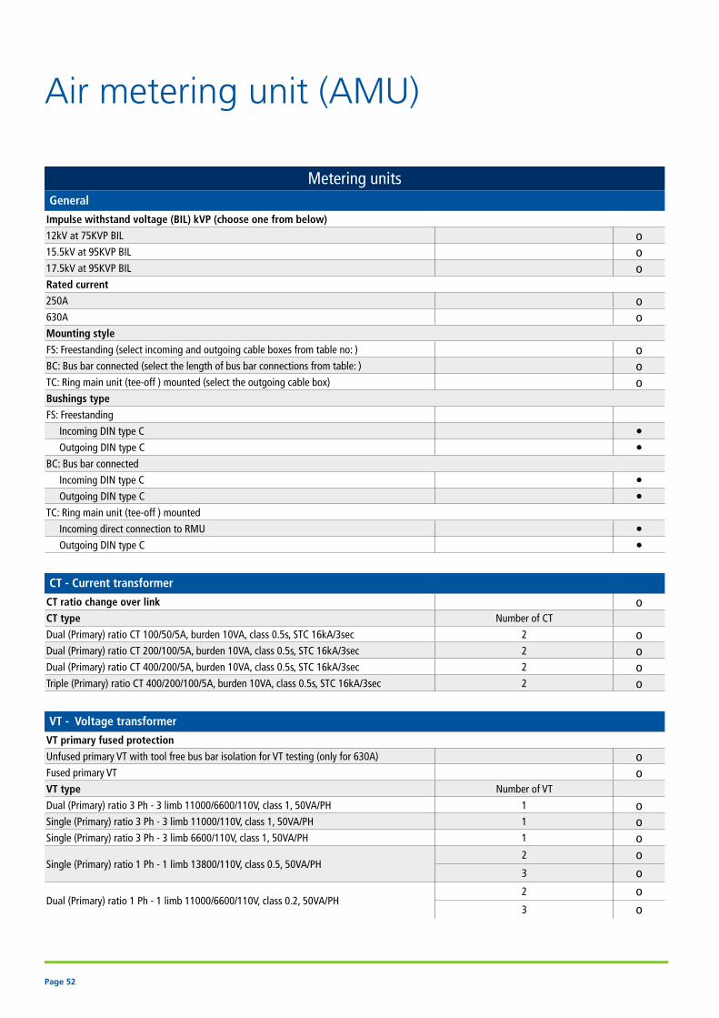
Air metering unit (AMU)
Metering unitsGeneral
Impulse withstand voltage (BIL) kVP (choose one from below)
12kV at 75KVP BIL o15.5kV at 95KVP BIL o17.5kV at 95KVP BIL oRated current
250A o630A oMounting style
FS: Freestanding (select incoming and outgoing cable boxes from table no: ) oBC: Bus bar connected (select the length of bus bar connections from table: ) oTC: Ring main unit (tee-off ) mounted (select the outgoing cable box) oBushings type
FS: Freestanding
Incoming DIN type C • Outgoing DIN type C •BC: Bus bar connected
Incoming DIN type C • Outgoing DIN type C •TC: Ring main unit (tee-off ) mounted
Incoming direct connection to RMU • Outgoing DIN type C •
CT - Current transformer
CT ratio change over link oCT type Number of CT
Dual (Primary) ratio CT 100/50/5A, burden 10VA, class 0.5s, STC 16kA/3sec 2 oDual (Primary) ratio CT 200/100/5A, burden 10VA, class 0.5s, STC 16kA/3sec 2 oDual (Primary) ratio CT 400/200/5A, burden 10VA, class 0.5s, STC 16kA/3sec 2 oTriple (Primary) ratio CT 400/200/100/5A, burden 10VA, class 0.5s, STC 16kA/3sec 2 o
VT - Voltage transformer
VT primary fused protection
Unfused primary VT with tool free bus bar isolation for VT testing (only for 630A) oFused primary VT oVT type Number of VT
Dual (Primary) ratio 3 Ph - 3 limb 11000/6600/110V, class 1, 50VA/PH 1 oSingle (Primary) ratio 3 Ph - 3 limb 11000/110V, class 1, 50VA/PH 1 oSingle (Primary) ratio 3 Ph - 3 limb 6600/110V, class 1, 50VA/PH 1 o
Single (Primary) ratio 1 Ph - 1 limb 13800/110V, class 0.5, 50VA/PH2 o3 o
Dual (Primary) ratio 1 Ph - 1 limb 11000/6600/110V, class 0.2, 50VA/PH2 o3 o

Page 53
Accessories
Shunt trip supply (110VAC to power shunt trip on RMU) oTrip lock out relay o
Secondary wiring protectionMCB oFuses o
Power meters
Metering wiring Wiring for single meter •Wiring for 2 meters o
Meter type
Circutor oActaris o
Any other (*) o
Number of meters1 o2 o
Meter mounting styleDoor mounted o
DIN mounted (window on the door) oMarshalling box gland plates
Blank gland plate o
Gland plate with 1 hole (hole size)20mm o25mm o
Gland plate with 2 holes (hole sizes)
20mm and 25mm o16mm and 25mm o20mm and 20mm o25mm and 25mm o
Any other hole sizes / combination(*) o
Key • Standard o Options

Page 54
Accessories
Cable box, cable gland and gland plate selection table
Ring switch 1
Ring switch 2
Circuit breaker tee-off
Extensible bus bars
Metering unit
(Not to be used with VRE
and DSE)
Incoming side
(for FS only)
Outgoing side
(for FS and TC only)
Interlocked cable box o o o - - -Cable box internal arc rated (AFL)Top entryIP50 (standard) • • • • • •IP54 (optional) o o o o o o450mm bushings to gland height,12.5KA IAC o o o o o o610 mm bushings to gland height,12.5KA IAC o o o o o oBottom entry (IP54)450mm bushings to gland height, 12.5 kA IAC o o o o o o610mm bushings to gland height, 12.5 kA IAC o o o o o o450mm bushings to gland height, 20KA IAC o o o o o o610mm bushings to gland height, 20KA IAC o o o o o oBottom entry angled, 12.5KA IAC o o o o - -Bottom entry deep, 12.5KA IAC o o o o - -Cable box non IAC ratedTop entryIP50 (standard) • • • • • •IP54 (optional) o o o o o o450mm bushings to gland height o o o o o o610mm bushings to gland height o o o o o oBottom entry (IP54)450mm bushings to gland height o o o o o o610mm bushings to gland height o o o o o oBottom entry angled o o o o - -Bottom entry deep o o o o - -1 X 3C cable gland and gland platesX size Gland plates X size gland plate with earth stud o o o o o o X size gland plate with earth bar o o o o o o Glands X tube glands o o o o o o X brass wiping gland o o o o o oY size Gland plates Y size gland with earth stud o o o o o o Y size gland with earth bar o o o o o o Glands Y tube glands o o o o o o Y brass wiping gland o o o o o o

Page 55
Cable box, cable gland and gland plate selection table
Ring Switch 1
Ring Switch 2
Circuit breaker tee-off
Extensible bus bars
Metering Unit
(Not to be used with VRE
and DSE)
Incoming side
(for FS only)
Outgoing side
(for FS and TC only)
3 x 1C cable gland and gland platesGland plates3 hole split steel with earth stud o o o o o o3 hole split steel with earth bar o o o o o o3 hole solid brass with earth stud o o o o o o3 hole solid brass with earth bar o o o o o oGlands
Single core compression gland o o o o o oSingle core heat shrink glands o o o o o o
Bus bar coupling selection table
Bus bar coupling kits (length mm) 241 378 453 500 750Insulation for bus bar couplingHeat shrink manufactured by SPS o - o o oHeat shrink manufactured by Raychem o - o o oHeat shrink manufactured by REPL • - • • •Cold fit rubber boot manufactured by Pirelli - • - - -
Other accessories Quantity
Padlocks
TLF fuses (specify quantity and Amp rating)
Foundation bolts (not required for transformer mounting)
Adaptor for converting parallel bushings to DIN 400 type C connection
Key • Standard o Options - Not applicable

Page 56
Sabre models and options order formTo use this form, please photocopy and return the completed form to your nearest Lucy Switchgear office Tick the boxes with your required order (addresses can be found on the back cover)
Name:
Address:
Company:
Tel No:
Fax No:
Email:
Order number:
Ring main units
Modular unitsRange Modular
circuit breaker
Modular ring switches
Extensibility Non extensible Extensible ExtensibleNon
extensible
Models VRN2a VRN6a VRNFS VRN24 VRE2a VRE6a VCE2a VCE6a SSE6a DSE6a DSN6a
Description 2 RSW+ 1VCB
2 RSW+ 1VCB
2 RSW+ 1VCB
2 RSW+ 1VCB
2 RSW+ 1VCB
2 RSW+ 1VCB 1VCB 1VCB 1 RSW 2 RSW 2 RSW
General ExtensibilityNon extensible • • • • - - - - - - •LH extensible - - - - -RH extensible - - - - -Both sides extensible - - - - -Impulse withstand voltage (BIL) kVP (choose one from below)
12kV at 75KVP BIL - - 15.5kV at 95KVP BIL - - 17.5kV at 95KVP BIL - - - - - - - - - -24kV at 125kVP BIL - - - - - - - - - -24kV at 145kVP BIL - - - - - - - - - -Low gas pressure alarm auxillary contact 1NO Pressure indicator gauge with Hanson coupling • • • • • • • • • • •Mounting style Transformer mounted unit (fitted with ESI flange) - - - - - - - - -Freestanding unit • • • • • • • • •No ESI flange (with cable box) - - -ESI transformer flange fitted (with/without cable box) - - -Height of tee-off bushing from floor (applicable to freestanding units)
1100mm - - - - - - - - -1320mm - - - - - - - -1348mm - - • - - - - - - - -1402mm - - - - - - - -Height of extension bushings from floor (applicable to free standing units)
1072 mm - - - - • • • • • • •Any other (available on request) - - - - Internal arc protection for gas chamber (tank)AF • • • • • • • • • • •AFL AFLR - Tank exhaust at top • • - - • • • • • • •Tank exhaust at rear - - • • - - - - - - -Extensible bus bar bushings: Obround (Hysol) - - - - • • • • • • -
Order quantity / number of units (please fill separate form for each type)

Page 57
Extensibility Non extensible Extensible ExtensibleNon
extensible
Models VRN2a VRN6a VRNFS VRN24 VRE2a VRE6a VCE2a VCE6a SSE6a DSE6a DSN6a
Description 2 RSW+ 1VCB
2 RSW+ 1VCB
2 RSW+ 1VCB
2 RSW+ 1VCB
2 RSW+ 1VCB
2 RSW+ 1VCB 1VCB 1VCB 1 RSW 2 RSW 2 RSW
Vacuum circuit breakerShort circuit breaking current
16kA RMS - - - • - - - - - - -20kA RMS • • - - • • • • - - -21kA RMS - - • - - - - - - - -25KA RMS - - - - - - -Bushings type
Parallel bushings • • - - • • • • - - -Adaptor to convert parallel bushings to DIN 400 type C bushing - - - - -DIN 400 type C - - • • - - - - - - -Rated normal current
250A • - - • • - - - -400A - - • • - - - - - - -630A - • - - • - • - - -Earth & test facility - - - - - - - -Circuit breaker protection
TLF - - - -Relay (choose one from below)
WIP1 relay - - - Fanox realy - - - Any other* - - -Protection (CT) current transformers
Dual (Primary) ratio CT 100/50/- - - -Dual (Primary) ratio CT 200/100/- - - -Triple (Primary) ratio CT 150/100/50/- - - -Dual (Primary) ratio CT 400/200/- - - - - - -Dual (Primary) ratio CT 150/100/- - - -Dual (Primary) ratio CT 600/200/- - - - - - - -Manual "Pull to trip" • • - - -Remote shunt trip
12V DC - - -24V DC - - -48V DC - - -110V DC - - -110V AC - - -240V AC - - -Multi voltage (24V AC/DC- 240V AC/DC) - - -Indication/ Auxilliary switches
Remote protection trip output signal (for TLF or relay trip status) 1N/O - - -
Watchdog for relays (only available with selective relays) - - -Tripped on fault indication - - -Circuit breaker actuator enabled indication - - -Circuit breaker service indication
1NO, 1NC - - -2NO, 2NC - - -

Page 58
Extensibility Non extensible Extensible ExtensibleNon
extensible
Models VRN2a VRN6a VRNFS VRN24 VRE2a VRE6a VCE2a VCE6a SSE6a DSE6a DSN6a
Description 2 RSW+ 1VCB
2 RSW+ 1VCB
2 RSW+ 1VCB
2 RSW+ 1VCB
2 RSW+ 1VCB
2 RSW+ 1VCB 1VCB 1VCB 1 RSW 2 RSW 2 RSW
Circuit breaker earth indication
1NO, 1NC - - -2NO, 2NC - - -Secondary injection terminals - - -VPIS
Neon indication push button - - -Neon indication pfisterer socket - - -Operation counter - - - -Castell locks
Key free earth on - - -Key trapped disconnector service CB ON - - -Actuators (motors)
Actuators wiring only - - -Actuators (24V DC motor) for remote control - - -Ring switch 1 (Left hand side)
Rated current
400A - - • - - - - - - - -630A • • • • • - - • • •Earth & test facility • • • • • • - - • • •Bushings type
DIN 400 type C • • • • • • - - • • •Operation counter - - -Actuators (motors)
Actuators wiring only - -Actuators (24V DC motor) for remote control - -VPIS
Neon indication push button - -Neon indication pfisterer socket - -MV sensor - -Auxilliary switches
1NO, 1NC - -2NO, 2NC - -Castell locks
Key free in off position - -Earth fault indication
BFZ-50 - -MFZ-50 - -MLZ-50 - -CFZ-50 - -CLZ-50 - -BLZ-50 - -Any other(*) - -Ring switch 2 (Right hand side)
Rated current
400A - - • - - - - - - - -630A • • • • • - - - • •
Sabre models and options order form - continued

Page 59
Extensibility Non extensible Extensible ExtensibleNon
extensible
Models VRN2a VRN6a VRNFS VRN24 VRE2a VRE6a VCE2a VCE6a SSE6a DSE6a DSN6a
Description 2 RSW+ 1VCB
2 RSW+ 1VCB
2 RSW+ 1VCB
2 RSW+ 1VCB
2 RSW+ 1VCB
2 RSW+ 1VCB 1VCB 1VCB 1 RSW 2 RSW 2 RSW
Ring switch 2 (Right hand side)
Earth & test facility • • • • • • - - - • •Bushings type
DIN 400 type C • • • • • • - - - • •Operation counter - - - -Actuators (motors)
Actuators wiring only - - -Actuators (24V DC motor) for remote control - - -VPIS
Neon indication push button - - -Neon indication pfisterer socket - - -MV sensor - - -Auxilliary switches
1NO, 1NC - - -2NO, 2NC - - -Castell locks
Key free in off position - - -Earth fault indication
BFZ-50 - - -MFZ-50 - - -MLZ-50 - - -CFZ-50 - - -CLZ-50 - - -BLZ-50 - - -Any other(*) - - -
* Please fill the details in comments section below.
Comments
Key • Standard Option select - Not applicable

Page 60
Air metering unit (AMU) order formTo use this form, please photocopy and return the completed form to your nearest Lucy Switchgear office Tick the boxes with your required order (addresses can be found on the back cover)
Name:
Address:
Company:
Tel No:
Fax No:
Email:
Order number:
Order quantity / number of units (please fill separate form for each type)
Metering unitsGeneral
Impulse withstand voltage (BIL) kVP (choose one from below)
12kV at 75KVP BIL
15.5kV at 95KVP BIL
17.5kV at 95KVP BIL
Rated current
250A
630A
Mounting style
FS: Freestanding (select incoming and outgoing cable boxes from table no: )
BC: Bus bar connected (select the length of bus bar connections from table: )
TC: Ring main unit (tee-off ) mounted (select the outgoing cable box:)
Bushings type
FS: Freestanding
Incoming DIN type C •
Outgoing DIN type C •BC: Bus bar connected
Incoming DIN type C •
Outgoing DIN type C •TC: Ring main unit (tee-off ) mounted
Incoming direct coonection to RMU •
Outgoing DIN type C •
CT - Current transformer
CT Ratio change over link
CT Type Number of CT
Dual (Primary) ratio CT 100/50/5A, burden 10VA, class 0.5s, STC 16kA/3sec 2
Dual (Primary) ratio CT 200/100/5A, burden 10VA, class 0.5s, STC 16kA/3sec 2
Dual (Primary) ratio CT 400/200/5A, burden 10VA, class 0.5s, STC 16kA/3sec 2
Triple (Primary) ratio CT 400/200/100/5A, burden 10VA, class 0.5s, STC 16kA/3sec 2

Page 61
VT - Voltage transformer
VT Primary fused protection
Unfused primary VT with tool free bus bar isolation for VT testing (only for 630A)
Fused primary VT
VT Type Number of VT
Dual (Primary) ratio 3 Ph - 3 limb 11000/6600/110V, class 1, 50VA/PH 1
Single (Primary) ratio 3 Ph - 3 limb 11000/110V, class 1, 50VA/PH 1
Single (Primary) ratio 3 Ph - 3 limb 6600/110V, class 1, 50VA/PH 1
Single (Primary) ratio 1 Ph - 1 limb 13800/110V, class 0.5, 50VA/PH2
3
Dual (Primary) ratio 1 Ph - 1 limb 11000/6600/110V, class 0.2, 50VA/PH2
3
Accessories
Shunt trip supply (110VAC to power shunt trip on RMU)
Trip lock out relay
Secondary wiring protectionMCB
Fuses
Power meters
Metering wiringWiring for single meter •
Wiring for 2 meters
Meter type
Circutor
Actaris
Any other (*)
Number of meters1
2
Meter mounting styleDoor mounted
Din mounted (window on the door)
Marshalling box gland plates
Blank gland plate
Gland plate with 1 hole (hole size)20mm
25mm
Gland plate with 2 holes (hole sizes)
20mm and 25mm
16mm and 25mm
20mm and 20mm
25mm and 25mm
Any other hole sizes/ combination(*)
Key • Standard Option select

Page 62
Sabre accessories order formTo use this form, please photocopy and return the completed form to your nearest Lucy Switchgear office Tick the boxes with your required order (addresses can be found on the back cover)
Name:
Address:
Company:
Tel No:
Fax No:
Email:
Order number:
Order quantity / number of units (please fill separate form for each type)
Cable box, cable gland and gland plate selection table
Ring switch 1
Ring switch 2
Circuit breaker tee-off
Extensible bus bars
Metering unit
(Not to be used with VRE
and DSE)
Incoming side
(for FS only)
Outgoing side
(for FS and TC only)
Interlocked cable box - - -Cable box internal arc rated (AFL)Top entry
IP50 (standard) • • • • • •IP54 (optional)
450mm bushings to gland height,12.5KA IAC
610 mm bushings to gland height,12.5KA IAC
Bottom entry (IP54)
450mm bushings to gland height, 12.5 kA IAC
610mm bushings to gland height, 12.5 kA IAC
450mm bushings to gland height, 20KA IAC
610mm bushings to gland height, 20KA IAC
Bottom entry angled, 12.5KA IAC - -Bottom entry deep, 12.5KA IAC - -Cable box non IAC rated
Top entry
IP50 (standard) • • • • • •IP54 (optional)
450mm bushings to gland height
610mm bushings to gland height
Bottom entry (IP54)
450mm bushings to gland height
610mm bushings to gland height
Bottom entry angled - -Bottom entry deep - -1 X 3C cable gland and gland plates
X size
Gland plates
X size gland plate with earth stud
X size gland plate with earth bar

Page 63
Cable box, cable gland and gland plate selection table
Ring switch 1
Ring switch 2
Circuit breaker tee-off
Extensible bus bars
Metering unit
(Not to be used with VRE
and DSE)
Incoming side
(for FS only)
Outgoing side
(for FS and TC only)
1 X 3C cable gland and gland plates
Glands
X tube glands
X brass wiping gland
Y size
Gland plates
Y size gland with earth stud
Y size gland with earth bar
Glands
Y tube glands
Y brass wiping gland
3 x 1C cable gland and gland plates
Gland plates
3 hole split steel with earth stud
3 hole split steel with earth bar
3 hole solid brass with earth stud
3 hole solid brass with earth bar
Glands
Single core compression gland
Single core heat shrink glands
Bus bar coupling selection table
Bus bar coupling kits (length mm) 241 378 453 500 750Insulation for bus bar coupling
Heat shrink manufactured by SPS -Heat shrink manufactured by Raychem -Heat shrink manufactured by REPL • - • • •Cold fit rubber boot manufactured by Pirelli - • - - -
Other accessories Quantity
Padlocks
TLF fuses (specify quantity and amp rating)
Foundation bolts (not required for transformer mounting)
Adaptor for converting parallel bushings to DIN400 type C connection
Key • Standard Option select - Not applicable
To find out more about us, visit:
www.lucyswitchgear.com
Lucy Switchgear Ltd. Howland Road, Thame, Oxfordshire,OX9 3UJ, United Kingdom Tel: +44 1844 267 267 GeneralTel: +44 1844 267 222 SalesFax: +44 1844 267 223 Email: [email protected]
Lucy Middle East FZEPO Box 17335, Jebel Ali, Dubai, United Arab Emirates Tel: +97 148 129 999Fax: +97 148 129 900 Email: [email protected]
Lucy Switchgear worldwide offices
Lucy Asia Pacific Sdn BhdL13A-03-03A, PJX-HM Shah Tower,No16A Jalan Persiaran Barat,46050 Petaling Jaya, Selangor, Malaysia Tel: +603 74910700Fax: +603 79316923Email: [email protected]
Lucy Electric (Beijing) Co. Ltd.卢西电器(北京)有限公司北京市朝阳区东三环北路霞光里18号佳程广场A座1122室邮编:100027电话:+86 1059 231 176传真:+86 1059 231 177电子邮件:[email protected]
Lucy Switchgear Arabia Co. Ltd.Novotel Business Centre,P.O. Box 35340, Dammam 31488,Saudi ArabiaTel: +966 3 8147 910Fax: +966 3 8147 914Email: [email protected]
Lucy Switchgear (South Africa)Unit 2, Cranberry Industrial Park, Cranberry StreetLaser Park, Honeydew, 2170, South AfricaTel: +27 11 025 7490Fax: +27 11 794 3277Email: [email protected]
Postal Address:P.O. Box 1078, Honeydew, 2040
DisclaimerLucy Switchgear has a policy of continuous research and development and accordingly reserves the right to change the design and specification of its products without prior notice or liability.