sae 2009 nvh conference structure borne nvh...
TRANSCRIPT

Slide 12009 SAE NVC Structure Borne Noise WorkshopAutomotive Analytics LLC 2009
SAE 2009 NVH ConferenceStructure Borne NVH Workshop
Presenters:
Alan DuncanAlan Duncan Automotive Analytics
Greg Greg GoetchiusGoetchius Material Sciences Corp.
JianminJianmin Guan Guan Altair Engineering
Contact Email: [email protected]
Contact Email: [email protected]
Contact Email: [email protected]

Slide 22009 SAE NVC Structure Borne Noise WorkshopAutomotive Analytics LLC 2009
Structure Borne NVH WorkshopWorkshop Objectives -1. Review Basic Concepts of Automotive Structure Borne Noise.
2. Propose Generic Targets.
3. Present Real World Application Example.
Intended Audience –• New NVH Engineers.
• “Acoustics” Engineers seeking new perspective.
• “Seasoned Veterans” seeking to brush up skills.
Slide 32009 SAE NVC Structure Borne Noise WorkshopAutomotive Analytics LLC 2009
Structure Borne NVH Workshop• Introduction• Low Frequency Basics• Mid Frequency Basics• Live Noise Attenuation Demo• Real World Application Example• Closing Remarks

Slide 42009 SAE NVC Structure Borne Noise WorkshopAutomotive Analytics LLC 2009
Structure Borne NVH Workshop
• Introduction• Low Frequency Basics• Mid Frequency Basics• Live Noise Attenuation Demo• Real World Application Example• Closing Remarks

Slide 52009 SAE NVC Structure Borne Noise WorkshopAutomotive Analytics LLC 2009
Rideand
Handling
NVH Durability
ImpactCrashWorthiness
Competing Vehicle Design Disciplines

Slide 62009 SAE NVC Structure Borne Noise WorkshopAutomotive Analytics LLC 2009
Structure Borne Noise and Vibration
VibratingSource
Frequency Range: up to 1000 HzSystem Characterization
• Source of Excitation• Transmission through Structural Paths • “Felt” as Vibration• “Heard” as Noise

Slide 72009 SAE NVC Structure Borne Noise WorkshopAutomotive Analytics LLC 2009
Structure Borne NoiseAirborne Noise
Res
pons
e
Log Frequency
“Low”Global Stiffness
“Mid”
Local Stiffness+
Damping
“High”
Absorption+
Mass+
Sealing+
Damping
~ 150 Hz ~ 1000 Hz ~ 10,000 Hz
Automotive NVH Frequency Range

Slide 82009 SAE NVC Structure Borne Noise WorkshopAutomotive Analytics LLC 2009
Structure Borne NVH Workshop
• Introduction• Low Frequency Basics• Mid Frequency Basics• Live Noise Attenuation Demo• Real World Application Example• Closing Remarks

Slide 92009 SAE NVC Structure Borne Noise WorkshopAutomotive Analytics LLC 2009
Low Frequency Basics• Source-Path-Receiver Concept• Single DOF System Vibration• NVH Source Considerations• Receiver Considerations• Vibration Attenuation Strategies
Provide Improved IsolationMode ManagementNodal Point MountingDynamic Absorbers

Slide 102009 SAE NVC Structure Borne Noise WorkshopAutomotive Analytics LLC 2009
Low Frequency Basics• Source-Path-Receiver Concept• Single DOF System Vibration• NVH Source Considerations• Receiver Considerations• Vibration Attenuation Strategies
Provide Improved IsolationMode ManagementNodal Point MountingDynamic Absorbers

Slide 112009 SAE NVC Structure Borne Noise WorkshopAutomotive Analytics LLC 2009
RECEIVER
PATH
SOURCE
Structure Borne NVH Basics

Slide 122009 SAE NVC Structure Borne Noise WorkshopAutomotive Analytics LLC 2009
Low Frequency Basics• Source-Path-Receiver Concept• Single DOF System Vibration• NVH Source Considerations• Receiver Considerations• Vibration Attenuation Strategies
Provide Improved IsolationMode ManagementNodal Point MountingDynamic Absorbers

Slide 132009 SAE NVC Structure Borne Noise WorkshopAutomotive Analytics LLC 2009
m
APPLIED FORCE
F = FO sin 2 π f t
k c FT
TR = FT / F
TransmittedForce
Single Degree of Freedom Vibration
= fraction of critical damping
fn = natural frequency
f = operating frequency
( )2n
22n
2
2n
ff2)ff(1)ff(21ζ
ζ+−
+=
ζmk

Slide 142009 SAE NVC Structure Borne Noise WorkshopAutomotive Analytics LLC 2009
0 1 2 3 4 50
1
2
3
4Tr
ansm
issi
bilit
y R
atio
1.414Frequency Ratio (f / fn)
Vibration Isolation Principle
m
APPLIED FORCEF = FO sin 2 π f t
k c FT
TR = FT / F
TransmittedForce
Isolation RegionIsolation Region
1.00.5
0.375
0.25
0.15
0.1
Slide 152009 SAE NVC Structure Borne Noise WorkshopAutomotive Analytics LLC 2009
Low Frequency Basics• Source-Path-Receiver Concept• Single DOF System Vibration• NVH Source Considerations• Receiver Considerations• Vibration Attenuation Strategies
Provide Improved IsolationMode ManagementNodal Point MountingDynamic Absorbers

Slide 162009 SAE NVC Structure Borne Noise WorkshopAutomotive Analytics LLC 2009
Two Main Sources
NVH Source Considerations
Suspension Powertrain

Slide 172009 SAE NVC Structure Borne Noise WorkshopAutomotive Analytics LLC 2009
Typical NVH Pathways to the Passenger
PATHS FOR
STRUCTURE BORNE
NVH

Slide 182009 SAE NVC Structure Borne Noise WorkshopAutomotive Analytics LLC 2009
Structure Borne NVH Sources

Slide 192009 SAE NVC Structure Borne Noise WorkshopAutomotive Analytics LLC 2009
Structure Borne NVH Sources
Primary Consideration:
Reduce the Source first as much as possible because whatever enters the structure is transmitted through multiple paths to the receiver.
Transmission through multiple paths is more subject to variability.

Slide 202009 SAE NVC Structure Borne Noise WorkshopAutomotive Analytics LLC 2009
Low Frequency Basics• Source-Path-Receiver Concept• Single DOF System Vibration• NVH Source Considerations• Receiver Considerations• Vibration Attenuation Strategies
Provide Improved IsolationMode ManagementNodal Point MountingDynamic Absorbers

Slide 212009 SAE NVC Structure Borne Noise WorkshopAutomotive Analytics LLC 2009
Receiver ConsiderationsSubjective to Objective Conversions
Subjective NVH Ratings are typically based on a 10 Point Scale resulting from Ride Testing
A 2 ≈≈≈≈ 1/2 A 1Represents 1.0 Rating Change
TACTILE: 50% reduction in motion
SOUND : 6.dB reduction in sound pressure level ( long standing rule of thumb )
Receiver Sensitivity is a Key Consideration

Slide 222009 SAE NVC Structure Borne Noise WorkshopAutomotive Analytics LLC 2009
Low Frequency Basics• Source-Path-Receiver Concept• Single DOF System Vibration• NVH Source Considerations• Receiver Considerations• Vibration Attenuation Strategies
Provide Improved IsolationMode ManagementNodal Point MountingDynamic Absorbers

Slide 232009 SAE NVC Structure Borne Noise WorkshopAutomotive Analytics LLC 2009
Total 2178.2 Kg (4800LBS)Mass Sprung 1996.7 Kg
Unsprung 181.5 Kg (8.33% of Total)Powertrain 181.5 Kg
Tires 350.3 N/mmKF 43.8 N/mmKR 63.1 N /mmBeam mass lumped on grids like a beam M2,3,4 =2 * M1,5
Symbolic Model of Unibody Passenger Car8 Degrees of Freedom
From Reference 6
318
2
6
4
75

Slide 242009 SAE NVC Structure Borne Noise WorkshopAutomotive Analytics LLC 2009
1 2 4 5
6 7
8
3
TiresWheels
SuspensionSprings
Engine Mass
EngineIsolator
Flexible Beam for Body
8 Degree of Freedom Vehicle NVH Model

Slide 252009 SAE NVC Structure Borne Noise WorkshopAutomotive Analytics LLC 2009
8 Degree of Freedom Vehicle NVH ModelForce Applied to Powertrain Assembly
Forces at Powertrain could represent a First OrderRotating Imbalance
Feng
1 2 4 5
6 7
8
3

Slide 262009 SAE NVC Structure Borne Noise WorkshopAutomotive Analytics LLC 2009
Engine Isolation Example
Response at Mid Car
0.0001
0.0010
0.0100
0.1000
1.0000
5.0 10.0 15.0 20.0Frequency Hz
Velo
city
(mm
/sec
)
Constant Force Load; F ~ A 15.9 Hz8.5 Hz7.0 Hz
700 Min. RPM First Order UnbalanceOperation Range of Interest
318
2
6
4
753311
8822
66
44
7755
Slide 272009 SAE NVC Structure Borne Noise WorkshopAutomotive Analytics LLC 2009
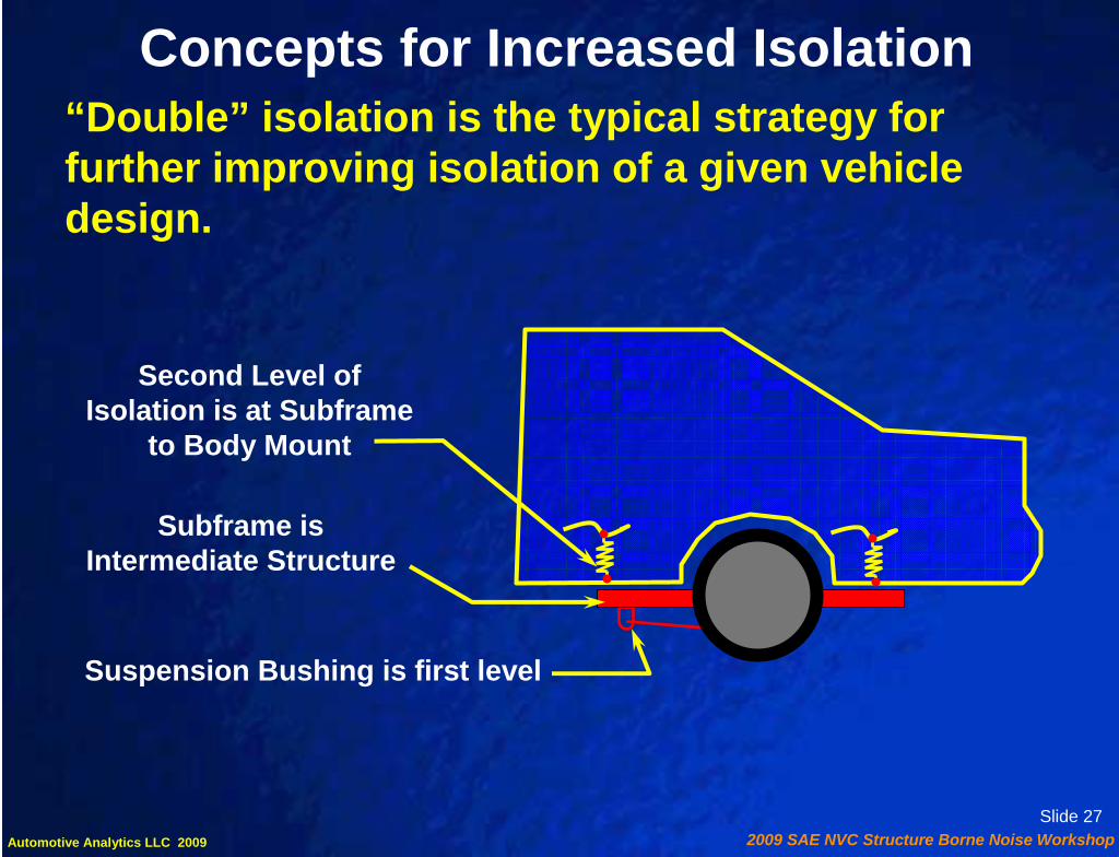
Concepts for Increased Isolation“Double” isolation is the typical strategy for further improving isolation of a given vehicle design.
Subframe is Intermediate Structure
Suspension Bushing is first level
Second Level of Isolation is at Subframe
to Body Mount
Slide 282009 SAE NVC Structure Borne Noise WorkshopAutomotive Analytics LLC 2009
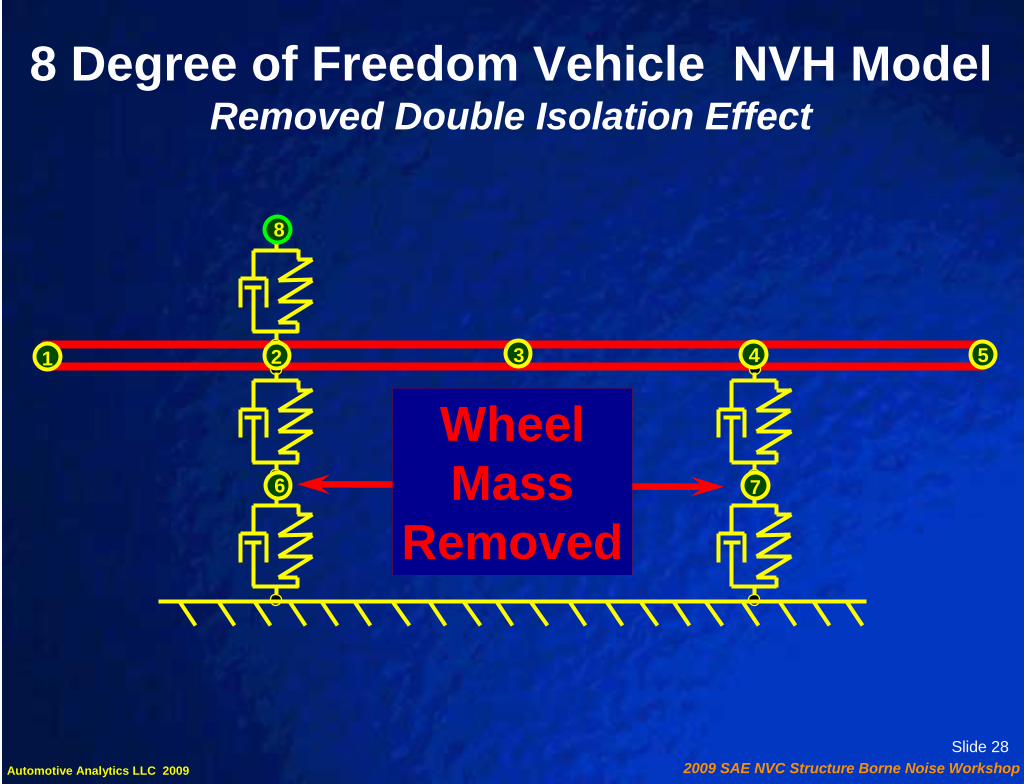
8 Degree of Freedom Vehicle NVH ModelRemoved Double Isolation Effect
WheelMass
Removed
1 2 4 5
6 7
8
3

Slide 292009 SAE NVC Structure Borne Noise WorkshopAutomotive Analytics LLC 2009
Double Isolation ExampleVertical Response at DOF3
0.0E+00
1.0E+00
2.0E+00
3.0E+00
4.0E+00
5.0E+00
6.0E+00
5.0 10.0 15.0 20.0Frequency Hz
Velo
city
(m
m/s
ec)
Base Model
Without Double_ISO
1.414*fn
318
2
6
4
753311
8822
66
44
7755
Slide 302009 SAE NVC Structure Borne Noise WorkshopAutomotive Analytics LLC 2009
Low Frequency Basics• Source-Path-Receiver Concept• Single DOF System Vibration• NVH Source Considerations• Receiver Considerations• Vibration Attenuation Strategies
Provide Improved IsolationMode ManagementNodal Point MountingDynamic Absorbers

Slide 312009 SAE NVC Structure Borne Noise WorkshopAutomotive Analytics LLC 2009
Mode Management Chart
0 5 10 15 20 25 30 35 40 45 50HzFirst Order Wheel/Tire Unbalance V8 Idle
Hot - Cold
EXCITATION SOURCESInherent Excitations (General Road Spectrum, Reciprocating Unbalance, Gas Torque, etc.)Process Variation Excitations (Engine, Driveline, Accessory, Wheel/Tire Unbalances)
Hz
Hz0 5 10 15 20 25 30 35 40 45 50
0 5 10 15 20 25 30 35 40 45 50
CHASSIS/POWERTRAIN MODES
Ride ModesPowertrain Modes
Suspension Hop and Tramp ModesSuspension Longitudinal Modes
Exhaust Modes
BODY/ACOUSTIC MODES
Body First Bending First Acoustic Mode
Steering Column First Vertical BendingBody First Torsion
(See Ref. 1)
Slide 322009 SAE NVC Structure Borne Noise WorkshopAutomotive Analytics LLC 2009
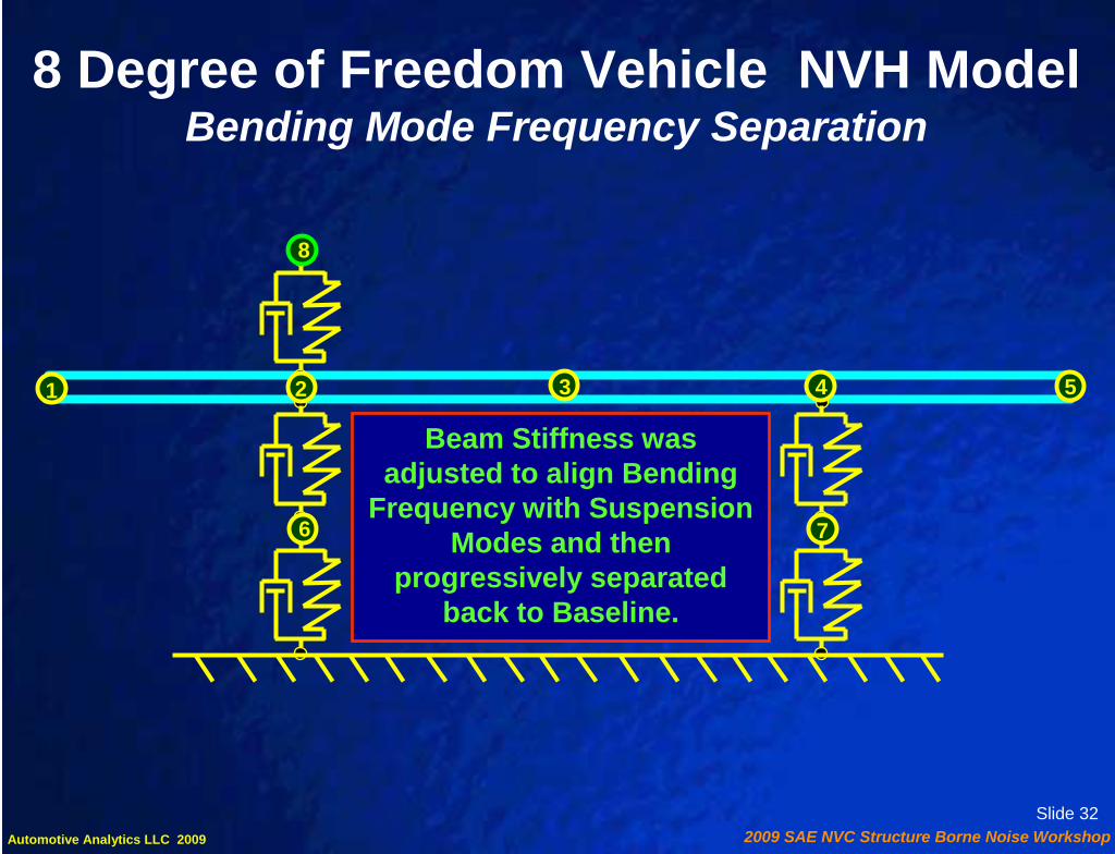
8 Degree of Freedom Vehicle NVH ModelBending Mode Frequency Separation
Beam Stiffness was adjusted to align Bending
Frequency with Suspension Modes and then
progressively separated back to Baseline.
1 2 4 5
6 7
8
3

Slide 332009 SAE NVC Structure Borne Noise WorkshopAutomotive Analytics LLC 2009
Response at Mid Car
0.10
1.00
10.00
100.00
5 10 15 20Frequency Hz
Velo
city
(mm
/sec
)
18.2 Hz Bending13.Hz Bending10.6 Bending
8 DOF Mode Separation Example
18.2 Hz13.0 Hz
10.6 Hz318
2
6
4
753311
8822
66
44
7755

Slide 342009 SAE NVC Structure Borne Noise WorkshopAutomotive Analytics LLC 2009
Low Frequency Basics• Source-Path-Receiver Concept• Single DOF System Vibration• NVH Source Considerations• Receiver Considerations• Vibration Attenuation Strategies
Provide Improved IsolationMode ManagementNodal Point MountingDynamic Absorbers
Slide 352009 SAE NVC Structure Borne Noise WorkshopAutomotive Analytics LLC 2009
Front input forces Rear input forces
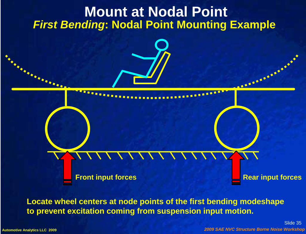
First Bending: Nodal Point Mounting ExampleMount at Nodal Point
Locate wheel centers at node points of the first bending modeshapeto prevent excitation coming from suspension input motion.

Slide 362009 SAE NVC Structure Borne Noise WorkshopAutomotive Analytics LLC 2009
Passenger sits at node point for First Torsion.
Side View
First Torsion: Nodal Point Mounting ExamplesMount at Nodal Point
Transmission Mount of a3 Mount N-S P/T is nearthe Torsion Node.
Rear View
Engine

Slide 372009 SAE NVC Structure Borne Noise WorkshopAutomotive Analytics LLC 2009
Powertrain Bending Mode Nodal Mounting
Mount system is placed to support Powertrain at the Nodal Locations of the First order Bending Mode. Best compromise with Plan View nodes should also be considered.
1 2 4 5
6 7
3

Slide 382009 SAE NVC Structure Borne Noise WorkshopAutomotive Analytics LLC 2009
1 2 4 5
6 7
8
3
8 Degree of Freedom Vehicle NVH ModelBending Node Alignment with Wheel Centers
Redistribute Beam Masses to move Node Points to
Align with points 2 and 4

Slide 392009 SAE NVC Structure Borne Noise WorkshopAutomotive Analytics LLC 2009
Response at Mid-Car
0.0E+00
1.0E+00
2.0E+00
3.0E+00
4.0E+00
5.0 10.0 15.0 20.0Frequency Hz
Velo
city
(m
m/s
ec)
Node ShiftedBase Model
First Bending Nodal Point Alignment
318
2
6
4
753311
8822
66
44
7755

Slide 402009 SAE NVC Structure Borne Noise WorkshopAutomotive Analytics LLC 2009
Low Frequency Basics• Source-Path-Receiver Concept• Single DOF System Vibration• NVH Source Considerations• Receiver Considerations• Vibration Attenuation Strategies
Provide Improved IsolationMode ManagementNodal Point MountingDynamic Absorbers

Slide 412009 SAE NVC Structure Borne Noise WorkshopAutomotive Analytics LLC 2009
YO
xSDOF
Dynamic Absorber Concept
MYO
x
Auxiliary Spring-Mass-Damperm = M / 10
2DOFM

Slide 422009 SAE NVC Structure Borne Noise WorkshopAutomotive Analytics LLC 2009
Powertrain Example of Dynamic Absorber
Anti-Node Identifiedat end of Powerplant
k c
Absorber attached at anti-node acting in the Vertical and Lateral plane.
Tuning Frequency = √√√√ k/m
m
[Figure Courtesy of DaimlerChrysler Corporation]

Slide 432009 SAE NVC Structure Borne Noise WorkshopAutomotive Analytics LLC 2009
Baseline Sound Level63 Hz Dynamic Absorber63 + 110 Hz Absorbers
Baseline Sound Level63 Hz Dynamic Absorber63 + 110 Hz Absorbers
[Figure Courtesy of DaimlerChrysler Corporation]
10 dB

Slide 442009 SAE NVC Structure Borne Noise WorkshopAutomotive Analytics LLC 2009
Low Frequency Basics - Review• Source-Path-Receiver Concept• Single DOF System Vibration• NVH Source Considerations• Receiver Considerations• Vibration Attenuation Strategies
Provide Improved IsolationMode ManagementNodal Point MountingDynamic Absorbers

Slide 452009 SAE NVC Structure Borne Noise WorkshopAutomotive Analytics LLC 2009
Structure Borne NVH Workshop
• Introduction• Low Frequency Basics• Mid Frequency Basics• Live Noise Attenuation Demo• Real World Application Example• Closing Remarks
Greg Goetchius

Slide 462009 SAE NVC Structure Borne Noise WorkshopAutomotive Analytics LLC 2009
Mid Frequency NVH Fundamentals
This looks familiar!Frequency Range of Interest has changed to
150 Hz to 1000 Hz

Slide 472009 SAE NVC Structure Borne Noise WorkshopAutomotive Analytics LLC 2009
Typical NVH Pathways to the Passenger
PATHS FOR
STRUCTURE BORNE
NVHNoise Paths are the
same as LowFrequency Region
Noise Paths are thesame as Low
Frequency Region
Slide 482009 SAE NVC Structure Borne Noise WorkshopAutomotive Analytics LLC 2009
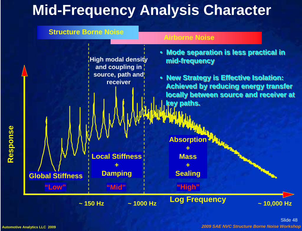
Mid-Frequency Analysis CharacterStructure Borne Noise
Airborne Noise
Res
pons
e
Log Frequency“Low”
Global Stiffness“Mid”
Local Stiffness+
Damping
“High”
Absorption+
Mass+
Sealing
~ 150 Hz ~ 1000 Hz ~ 10,000 Hz
High modal densityand coupling in
source, path andreceiver
• Mode separation is less practical inmid-frequency
• New Strategy is Effective Isolation:Achieved by reducing energy transferlocally between source and receiver atkey paths.
•• Mode separation is less practical inMode separation is less practical inmidmid--frequencyfrequency
•• New Strategy is Effective Isolation:New Strategy is Effective Isolation:Achieved by reducing energy transferAchieved by reducing energy transferlocally between source and receiver atlocally between source and receiver atkey paths.key paths.

Slide 492009 SAE NVC Structure Borne Noise WorkshopAutomotive Analytics LLC 2009
Control Measures for Mid Frequency Concerns
Effective Isolation
Attenuation along Key Noise Paths
Mid-Frequency Analysis Character

Slide 502009 SAE NVC Structure Borne Noise WorkshopAutomotive Analytics LLC 2009
Control Measures for Mid Frequency Concerns
Effective Isolation
Attenuation along Key Noise Paths
Mid-Frequency Analysis Character
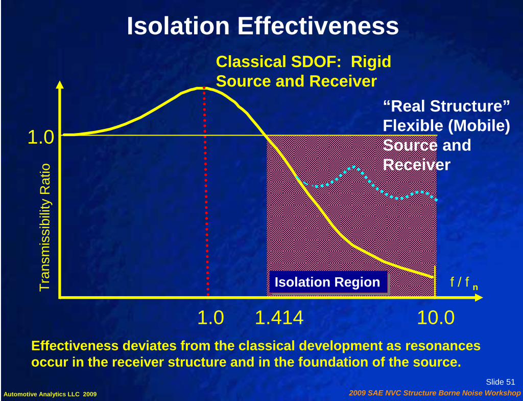
Slide 512009 SAE NVC Structure Borne Noise WorkshopAutomotive Analytics LLC 2009
Classical SDOF: Rigid Source and Receiver
T ran
smis
sib i
lity
Rat
io
1.0 1.414 10.0
f / f n
“Real Structure”Flexible (Mobile)Source and Receiver
Isolation Effectiveness
Effectiveness deviates from the classical development as resonances occur in the receiver structure and in the foundation of the source.
Isolation RegionIsolation Region
1.0

Slide 522009 SAE NVC Structure Borne Noise WorkshopAutomotive Analytics LLC 2009
Mobility• Mobility is the ratio of velocity response at the excitation point on structure
where point force is applied
Mobility =Velocity
Force
• Mobility, related to Admittance, characterizes Dynamic Stiffness of the structure at load application point
Mobility =Frequency * Displacement
Force
=Frequency
Dynamic Stiffness

Slide 532009 SAE NVC Structure Borne Noise WorkshopAutomotive Analytics LLC 2009
• The isolation effectiveness can be quantified by a theoretical model based on analysis of mobilities of receiver, isolator and source
• Transmissibility ratio is used to objectively define measure of isolation
TR =Force from source without isolator
Force from source with isolator
Isolation
V r
V ir
V is
F rF ir
Receiver
Source
F is
Fs V s
Isolator
VF s=
Y i + Y r + Y s
V r
F r
Receiver
Source
F s V s
VF s=
Y r + Y s
VV

Slide 542009 SAE NVC Structure Borne Noise WorkshopAutomotive Analytics LLC 2009
TR = ( Y r + Y s ) //// ( Y i + Y r + Y s )
• For Effective Isolation (Low TR) the Isolator Mobility must exceed the sum of the Source and Receiver Mobilities.
Y r : Receiver mobility
Y s : Source mobility
Y i : Isolator mobility
V m
V im
V if
F mF im
Receiver
Source
F if
F f V f
Isolator
TR = Force from source without an isolator Force from source with an isolator
Isolation
Recall that K 1Y ∝

Slide 552009 SAE NVC Structure Borne Noise WorkshopAutomotive Analytics LLC 2009
TR = ( ) //// ( ) K body
1K source
1+ K body
1 + K iso
1K source
1+
K iso
K sourceK body
K iso1.0 5.0 20.0
1.0
5.0
20.0
0.67 0.55 0.51
0.55 0.29 0.20
0.51 0.20 0.09
Generic targets:body to bushing stiffness ratio of at least 5.0source to bushing stiffness ratio of at least 20.0
Designing Noise Paths

Slide 562009 SAE NVC Structure Borne Noise WorkshopAutomotive Analytics LLC 2009
Stiffness Ratio; K body / K iso
Tran
smis
sibi
lity
Rat
io T
RBody-to-Bushing Stiffness RatioRelationship to Transmissibility
0
0.1
0.2
0.3
0.4
0.5
0.6
1 2 3 4 5 6 7 8 9 10
Target Min. = 5 gives TR = .20
For a source ratio of 20

Slide 572009 SAE NVC Structure Borne Noise WorkshopAutomotive Analytics LLC 2009
Control Measures for Mid Frequency Concerns
Effective Isolation
Attenuation along Key Noise Paths
Mid-Frequency Analysis Character

Slide 582009 SAE NVC Structure Borne Noise WorkshopAutomotive Analytics LLC 2009
Identifying Key NVH PathsKey NVH paths are identified by Transfer Path Analysis (TPA)
Fi
TactileTransferTactile
TransferAcousticTransfer
AcousticTransfer
Operating loads Operating loads
Break the system at the points where the forces enter the body (Receiver)
Total Acoustic Response is summation of partial responses over all noise paths
Pt = ΣΣΣΣ paths [Pi ] = ΣΣΣΣ paths [ (P/F) i * Fi ]

Slide 592009 SAE NVC Structure Borne Noise WorkshopAutomotive Analytics LLC 2009
Designing Noise Paths
Fi
Acoustic Transfer (P/F)iAcoustic Transfer (P/F)i
Operating loads createForces (Fi) into body atAll noise paths
F FF F
FF F
Pt = ΣΣΣΣ paths [Pi ] = ΣΣΣΣ paths [ Fi * (P/F) i ] = ΣΣΣΣ paths [ Fi * (P/V) i * (V/F)i]
P/V
P/F(Kbody)
V/F
Measurement Parameters Generic Targets
P/F Acoustic Sensitivity 50 - 60 dBL/N
V/F Structural Point Mobility (Receiver Side)
0.2 to 0.3 mm/sec/N

Slide 602009 SAE NVC Structure Borne Noise WorkshopAutomotive Analytics LLC 2009
Recall for Acoustic Response Pt
Pt = ΣΣΣΣ paths [Pi ] = ΣΣΣΣ paths [ Fi * (P/V) i * (V/F)i]
“Downstream” Effects: Body Panels
(P/V)i !!!! “Downstream” (Body Panel) System Dynamics: Three Main Effects:
Increased Damping
Increased Stiffness
1. Panel Damping
2. Panel Stiffness
3. Panel Acoustic Contribution

Slide 612009 SAE NVC Structure Borne Noise WorkshopAutomotive Analytics LLC 2009
Generic Noise Path Targets
K iso
K body> 5.0
K iso
K source
> 20.0
AcousticSensitivity < 50 - 60
dBL/N
StructuralMobility < 0.2 to 0.3 mm/sec/N
Panel Damping Loss Factor> .10
Primary: Minimize the Source Force< 1.0 N

Slide 622009 SAE NVC Structure Borne Noise WorkshopAutomotive Analytics LLC 2009
Final Remarks on Mid Frequency Analysis
• Effective isolation at dominant noise paths is critical• Effective isolation at dominant noise paths is critical
• Reduced mobilities at body & source and softenedbushing are key for effective isolation
• Reduced mobilities at body & source and softenedbushing are key for effective isolation
• Other means of dealing with high levels of response(Tuned dampers, damping treatments, isolatorplacement at nodal locations) are also effective
• Other means of dealing with high levels of response(Tuned dampers, damping treatments, isolatorplacement at nodal locations) are also effective
• Mode Separation remains a valid strategy as modesin the source structure start to participate
• Mode Separation remains a valid strategy as modesin the source structure start to participate

Slide 632009 SAE NVC Structure Borne Noise WorkshopAutomotive Analytics LLC 2009
Structure Borne NVH: Concepts Summary
• Source-Path-Receiver as a system1. Reduce Source
2. Rank and Manage Paths
3. Consider Subjective Response
• Effective Isolation
• Mode Management
• Nodal Point Placement
• Attachment Stiffness
• “Downstream” (Body Panel) Considerations
• Source-Path-Receiver as a system1. Reduce Source
2. Rank and Manage Paths
3. Consider Subjective Response
• Effective Isolation
• Mode Management
• Nodal Point Placement
• Attachment Stiffness
• “Downstream” (Body Panel) Considerations

Slide 642009 SAE NVC Structure Borne Noise WorkshopAutomotive Analytics LLC 2009
Structure Borne NVH Workshop
• Introduction• Low Frequency Basics• Mid Frequency Basics• Live Noise Attenuation Demo• Real World Application Example• Closing Remarks

Slide 652009 SAE NVC Structure Borne Noise WorkshopAutomotive Analytics LLC 2009
Toolbox Demo Noise Test Results
85
61
68
63
55
47
39
30
40
50
60
70
80
90
1) Baseline:Imbalance, No
Isolation
2) Imbalance +Isolation
3) No Imbalance,No Isolation
4) No Imbalance,No Isolation +
Damping
5) No Imbalance +Isolation +Damping
6) #5 + Absorption 7) #6 + InsulatorMat
SPL
(dB
A)
Tool Box Demo Test Results

Slide 662009 SAE NVC Structure Borne Noise WorkshopAutomotive Analytics LLC 2009
Structure Borne NVH Workshop
• Introduction• Low Frequency Basics• Mid Frequency Basics• Live Noise Attenuation Demo• Real World Application Example• Closing Remarks Jianmin Guan
Slide 672009 SAE NVC Structure Borne Noise WorkshopAutomotive Analytics LLC 2009
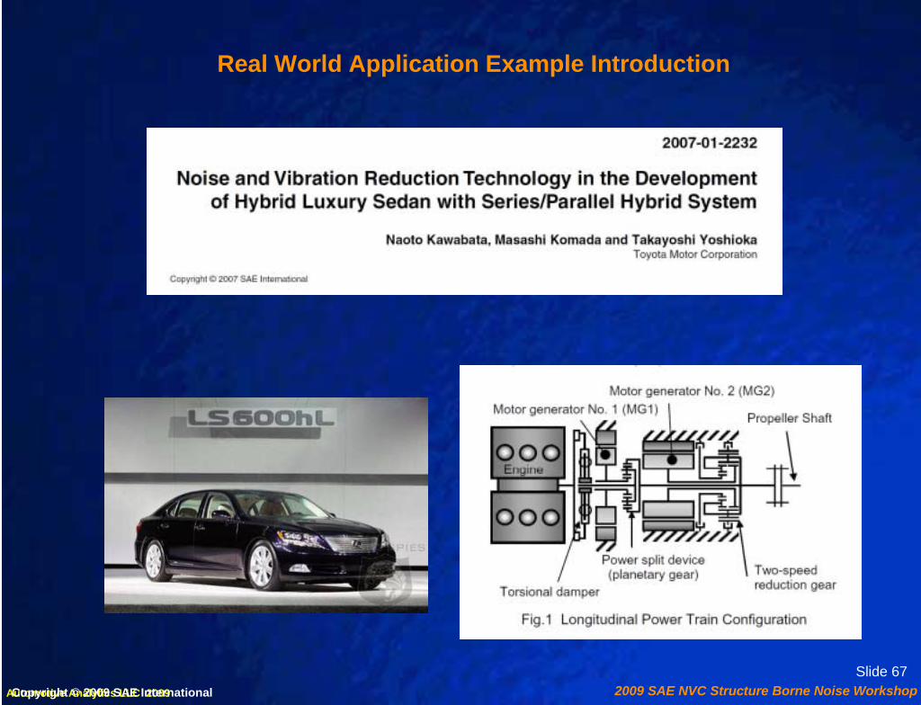
Real World Application Example Introduction
Copyright © 2009 SAE International

Slide 682009 SAE NVC Structure Borne Noise WorkshopAutomotive Analytics LLC 2009
Quietness during Idle and Electric-Vehicle Operation
Reduce Inverter Water Pump Loads:
1. Reduce pump impeller imbalance2. Redesign bearing structure3. Changing motor structure
Improve Isolation from Body:
1. Install rubber isolator2. Increase mounting bracket rigidity3. Improve Inverter case
Root Cause Diagnostics:
1. Water pump in the inverter cooling system2. Electromagnetic noise of the motor,
the inverter, and other units
Copyright © 2009 SAE International

Slide 692009 SAE NVC Structure Borne Noise WorkshopAutomotive Analytics LLC 2009
Quietness during Idle and Electric-Vehicle Operation
Reduce Inverter Water Pump Loads:
1. Reduce pump impeller imbalance2. Redesign bearing structure3. Changing motor structure
Improve Isolation from Body:
1. Install rubber isolator2. Increase mounting bracket rigidity3. Improve Inverter case
Root Cause Diagnostics:
1. Water pump in the inverter cooling system2. Electromagnetic noise of the motor,
the inverter, and other units
Reduce Source
EffectiveIsolation
Attach.Stiffness
Downstream
Copyright © 2009 SAE International

Slide 702009 SAE NVC Structure Borne Noise WorkshopAutomotive Analytics LLC 2009
Engine Start Vibration
Reduce Effect of Engine Loads:
1. Operating MG1 at high torque during engine start2. Implement vibration-reducing motor control3. Use two stage hysteretic torsional damper4. Shorten distance between principal elastic
axis and center of gravity of power plant
Root Cause Diagnostics:
1. Engine torque fluctuations2. Engine torque reaction forces
Reduce Torque Fluctuation:
1. Change intake valve closing timing2. Control piston stop position3. Adjust injected fuel volume and
ignition timing
Copyright © 2009 SAE International

Slide 712009 SAE NVC Structure Borne Noise WorkshopAutomotive Analytics LLC 2009
Engine Start Vibration
Reduce Effect of Engine Loads:
1. Operating MG1 at high torque during engine start2. Implement vibration-reducing motor control3. Use two stage hysteretic torsional damper4. Shorten distance between principal elastic
axis and center of gravity of power plant
Root Cause Diagnostics:
1. Engine torque fluctuations2. Engine torque reaction forces
Reduce Torque Fluctuation:
1. Change intake valve closing timing2. Control piston stop position3. Adjust injected fuel volume and
ignition timingReduce Source
Mode Manage.
Damper
EffectiveIsolation
Copyright © 2009 SAE International

Slide 722009 SAE NVC Structure Borne Noise WorkshopAutomotive Analytics LLC 2009
2nd Order Engine Induced Boom
Root Cause Diagnostics:
1. 2nd order couple of the reciprocating inertia of piston2. THS II Trans 50 mm longer and 35 kg heavier3. Lower power plant bending mode4. Requires 1.5X higher mount rates
Reduce Effect of 2nd order Couple:
1. Increase power plant bending mode2. Move mount to a nodal point3. Embed mounts inside cross member4. Reduces distance from principle
elastic axis to CG 5. Optimized vertical to lateral rate ratio
Copyright © 2009 SAE International

Slide 732009 SAE NVC Structure Borne Noise WorkshopAutomotive Analytics LLC 2009
2nd Order Engine Induced Boom
Root Cause Diagnostics:
1. 2nd order couple of the reciprocating inertia of piston2. THS II Trans 50 mm longer and 35 kg heavier3. Lower power plant bending mode4. Requires 1.5X higher mount rates
Reduce Effect of 2nd order Couple:
1. Increase power plant bending mode2. Move mount to a nodal point3. Embed mounts inside cross member4. Reduces distance from principle
elastic axis to CG 5. Optimized vertical to lateral rate ratio
Mode Manage.
Nodal Mounting
EffectiveIsolation
Copyright © 2009 SAE International

Slide 742009 SAE NVC Structure Borne Noise WorkshopAutomotive Analytics LLC 2009
Engine Radiated Noise
Reduce Effect of 24th order Loads:
1. Modified Trans case to improve modes2. Added dynamic damper at a high amp. point
on Trans case3. Added ribs in high radiating area of Trans case
Root Cause Diagnostics:
1. 24th MG2 order excitation2. Lower MG2 reduction gear ratio3. Lower transmission bending mode
- two key modes identified
Reduce 24th order Loads:
Arranged permanent magnets in V shape with optimized angle
Copyright © 2009 SAE International

Slide 752009 SAE NVC Structure Borne Noise WorkshopAutomotive Analytics LLC 2009
Engine Radiated Noise
Reduce Effect of 24th order Loads:
1. Modified Trans case to improve modes2. Added dynamic damper at a high amp. point
on Trans case3. Added ribs in high radiating area of Trans case
Root Cause Diagnostics:
1. 24th MG2 order excitation2. Lower MG2 reduction gear ratio3. Lower transmission bending mode
- two key modes identified
Reduce 24th order Loads:
Arranged permanent magnets in V shape with optimized angle
Mode Manage.
Reduce Source
Damper
Downstream
Copyright © 2009 SAE International

Slide 762009 SAE NVC Structure Borne Noise WorkshopAutomotive Analytics LLC 2009
Structure Borne NVH Workshop
• Introduction• Low Frequency Basics• Mid Frequency Basics• Live Noise Attenuation Demo• Real World Application Example• Closing Remarks

Slide 772009 SAE NVC Structure Borne Noise WorkshopAutomotive Analytics LLC 2009
Structure Borne NVH: Concepts Summary
• Source-Path-Receiver as a system1. Reduce Source
2. Rank and Manage Paths
3. Consider Subjective Response
• Effective Isolation
• Mode Management
• Nodal Point Placement
• Attachment Stiffness
• “Downstream” (Body Panel) Considerations
• Source-Path-Receiver as a system1. Reduce Source
2. Rank and Manage Paths
3. Consider Subjective Response
• Effective Isolation
• Mode Management
• Nodal Point Placement
• Attachment Stiffness
• “Downstream” (Body Panel) Considerations

Slide 782009 SAE NVC Structure Borne Noise WorkshopAutomotive Analytics LLC 2009
SAE 2009 NVH ConferenceStructure Borne NVH Workshop
Thank You for Your Time!
Q & AQ & A

Slide 792009 SAE NVC Structure Borne Noise WorkshopAutomotive Analytics LLC 2009
Primary References (Workshop Basis: 4 Papers)
1. A. E. Duncan, et. al., “Understanding NVH Basics”, IBEC, 1996
2. A. E. Duncan, et. al., “MSC/NVH_Manager Helps Chrysler Make Quieter Vibration-free Vehicles”, Chrysler PR Article, March 1998.
3. B. Dong, et. al., “Process to Achieve NVH Goals: Subsystem Targets via ‘Digital Prototype’ Simulations”, SAE 1999-01-1692, NVH Conference Proceedings, May 1999.
4. S. D. Gogate, et. al., “’Digital Prototype’ Simulations to Achieve Vehicle Level NVH Targets in the Presence of Uncertainties’”,
SAE 2001-01-1529, NVH Conference Proceedings, May 2001
Structure Borne NVH References
WS + Refs. at www.AutoAnalytics.com/papers.html
Structure Borne NVH Workshop - on InternetAt SAE www.sae.org/events/nvc/specialevents.htm

Slide 802009 SAE NVC Structure Borne Noise WorkshopAutomotive Analytics LLC 2009
Supplemental Reference Recommendations
5. T.D. Gillespie, Fundamentals of Vehicle Dynamics, SAE 1992(Also see SAE Video Lectures Series, same topic and author)
6. D. E. Cole, Elementary Vehicle Dynamics, Dept. of Mechanical Engineering, University of Michigan, Ann Arbor, Michigan, Sept. 1972
7. J. Y. Wong, Theory of Ground Vehicles, John Wiley & Sons, New York, 1978
8. N. Takata, et.al. (1986), “An Analysis of Ride Harshness” Int. Journal of Vehicle Design, Special Issue on Vehicle Safety, pp. 291-303.
9. T. Ushijima, et.al. “Objective Harshness Evaluation” SAE Paper No. 951374, (1995).
Structure Borne NVH References