sae baja- final drive gearbox
TRANSCRIPT

SAE Baja: Final Drive Gearbox
by
Michael McCausland Michael Watkins
Ian Masterson Andrew Sommer
Mechanical Engineering Department
California Polytechnic State University, San Luis Obispo
September, 2010
© Michael McCausland, Michael Watkins, Ian Masterson and Andrew Sommer

Statement of Disclaimer
Since this project is a result of a class assignment, it has been graded and accepted as fulfillment of the course requirements. Acceptance does not imply technical accuracy or reliability. Any use of information in this report is done at the risk of the user. These risks may include catastrophic failure of the device or infringement of patent or copyright laws. California Polytechnic State University at San Luis Obispo and its staff cannot be held liable for any use or misuse of the project.

Final Drive Gearbox Cal Poly SAE Baja

i
Table of Contents
List of Tables ................................................................................................................................. iii List of Figures ................................................................................................................................ iv Abstract ........................................................................................................................................ vi Chapter 1. Introduction ............................................................................................................................ 1
1.1. Objectives ....................................................................................................................... 1 1.2. Management Plan ........................................................................................................... 3
2. Background ............................................................................................................................. 4
3. Design Development ............................................................................................................... 6
3.1. CVT and Reverse Spur Gear ............................................................................................. 7 3.2. CVT and Planetary Reduction ........................................................................................... 7
3.2.1. GX7 CVT and Planetary Reduction and Secondary Sprocket Reduction ..................... 7 3.2.2. CVTech or Gaged CVT with Planetary Reduction and Reverse ................................... 10 3.2.3. Planetary Gearbox Shift Mechanism ......................................................................... 12
3.3. Manual Transmission ....................................................................................................... 13 3.3.1. Manual Transmission Shift Mechanism ..................................................................... 18 3.3.2. Manual Transmission Clutch Setup ........................................................................... 19
4. Final Design ............................................................................................................................. 19
4.1. Gears ............................................................................................................................... 20 4.2. Case ................................................................................................................................ 21 4.3. Sequential Shift Assembly ................................................................................................ 23 4.4. Final Output Assembly ..................................................................................................... 27 4.5. Clutch Assembly .............................................................................................................. 28 4.6. Secondary Sprocket and Adapter ..................................................................................... 30
5. Analysis .................................................................................................................................. 30
5.1. ADAMS - Rigid Body Dynamic Simulation ........................................................................ 31 5.2. Stress .............................................................................................................................. 34
6. Product Realization ................................................................................................................. 35 6.1. Sprocket Adapter ............................................................................................................ 36 6.2. Shift Lever ....................................................................................................................... 38 6.3. Covers ............................................................................................................................. 39 6.4. Output Shaft .................................................................................................................... 40 6.5. Gears .............................................................................................................................. 41 6.6. Cases ............................................................................................................................... 42
6.6.1. Investment Casting ................................................................................................. 43 6.6.2. Full CNC Machining ................................................................................................. 46

ii
7. Design Verification (Testing) .................................................................................................... 48
7.1. Material Hardness ........................................................................................................... 49
8. Conclusions and Recommendations ........................................................................................ 52 Appendix A Pertinent Rules from Baja SAE Rules Committee .................................................. 53 Appendix B Quality Function Deployment (QFD) ...................................................................... 55 Appendix C Gantt Chart .......................................................................................................... 56 Appendix D ASTM E140-97 Table 2 .......................................................................................... 57 Appendix E Stress Analysis ..................................................................................................... 58 Appendix F Output Assembly Final Drawings and Parts List .................................................... 61 Appendix G CNC procedures .................................................................................................... 68

iii
List of Tables Table 1. Planetary Reduction and Secondary Sprocket Reduction Cost Analysis............................... 9 Table 2. Planetary configuration cost analysis.................................................................................. 12 Table 3. A comparison of several aftermarket and OEM transmissions................................................ 15 Table 4. Sequential Shift Assembly Analysis (Cable Linkage)............................................................. 26 Table 5. Sequential Shift Assembly Analysis (Rod Linkage)............................................................... 26 Table 6. Output assembly cost........................................................................................................ 28 Table 7. AGMA and Lewis-bending results...................................................................................... 34 Table 8. Experimental test of the 54T QTC gear hardness................................................................ 51
iv
List of Figures Figure 1. Table of Requirements for formal engineering requriements............................................ 2 Figure 2. Planetary reduction mechanism of Patent No. 4502353..................................................... 4 Figure 3. Horsepower and Torque curve for Briggs & Stratton 10 hp Intek model 20 engine............ 5 Figure 4. Baja Vehicle solid model to be used for overall layout and system design........................... 6 Figure 5. Sketch of Planetary Reduction and Secondary Sprocket Reduction.................................... 8 Figure 6. Sketch of Planetary Reduction and Secondary Sprocket Reduction.................................... 11 Figure 7. Proposed manual transmission system layout.................................................................. 14 Figure 8. 400EX vehicle speed and shift locations................................................................................ 16 Figure 9. 185s vehicle speed and shift locations.................................................................................. 17 Figure 10. Kawasaki Bayou vehicle speed and shift locations............................................................... 18 Figure 11. Representative ratcheting shift drum.............................................................................. 19 Figure 12. 1994 Kawasaki Bayou 220 transmission assembly........................................................... 20 Figure 13. Exterior of transmission case CAD model......................................................................... 23 Figure 14. Lengths of rod setup used for the travel calculations..................................................... 24 Figure 15. Applied forces on the rod used for the buckling calculation............................................. 25 Figure 16. CAD schematic of output assembly................................................................................. 27 Figure 17. Available tractive effort (lbf) applied to road surface at rear wheels................................. 30 Figure 18. Power loss due to combined aerodynamic drag and road resistance................................ 31 Figure 19. ADAMS model (a), force and torque vectors during simulation (b)................................... 32 Figure 20. FFT spectrum for 1st gear engagement with an eccentric tooth........................................ 32 Figure 21. Shock torque applied to output shaft as vehicle lands..................................................... 33 Figure 22. Overlapping force profiles indicate the load sharing of the contact ratio.......................... 34 Figure 23. Completed sprocket adapter.......................................................................................... 36

v
Figure 24. Spline adapter being pressed into the main body of the sprocket adapter........................ 37 Figure 25. The final output shaft contains both gear spline and CVJ spline profiles............................ 41 Figure 26. Quality Transmission Components 55T gear mated to the final output shaft..................... 42 Figure 27. Image of the Haas CNC milling center during its first operation on the first setup............. 44 Figure 28. Aluminum case half immediately after removal from the plaster...................................... 45 Figure 29. Example of carbide insert endmills................................................................................... 47 Figure 30. Completed case half prior to bearing surface re-machining.............................................. 48 Figure 31. Schematic of a Rockwell Hardness Test............................................................................ 50 Figure 32. Test locations for the material hardness test................................................................... 51

vi
Abstract
This paper presents the results of a manual transmission project for SAE Baja. A full engineering
process is documented, including problem definition, scheduling, conceptualization, decision theory,
synthesis, analysis, manufacturing, and testing. A comparison is made between existing and potential
mechanical power train solutions. The final design is analyzed in dynamic simulations, AGMA stress,
predicted FFT spectrums, and shifting rod buckling. A number of complicated parts are manufactured
through investment casting and direct CNC machining. Issues in the final assembly have prevented the
project from being fully realized, recommendations are made for future SAE Baja teams.

1 / 60
1. Introduction
The goal of this project will be to design and implement a complete manual transmission for usage
in the Society of Automotive Engineers (SAE) mini Baja vehicle. The timeline for this project spans the
summer of 2009 and concludes after the mini Baja team's competition in western Washington in May of
2010.
This manual transmission is aimed towards improving the scores of the Baja team in both the rock
crawl event and the static presentations. Additional benefits can be gained in the maneuverability events
should the course be designed as a low-speed, low-turning radius biased event. In the present
configuration, the transmission does not implement reverse, and as such has hindered the performance of
the vehicle in previous competitions where the course layout necessitates improved maneuverability.
Specifically, in the 2009 competition the team only scored 27.81 out of 75 total points in the rock crawl
event as a result of having a large low-speed turning radius. A reverse gear would have allowed the driver
to continue on through the course and ultimately yield a higher score for that event. Additional gains can
be seen in the sales event of the competition, where a reverse gear makes the car more marketable and
appealing.
1.1 Objectives
The main goal of this new iteration is to add a reverse gear to the final drive gearbox without
damaging the existing performance of the vehicle in the 2009 configuration. The final concept selected by
the team has shown a theoretical improvement to the vehicle’s performance in all categories. In order to
reach these comprehensive objectives, the following list of project specifications has been developed:
• Design for CVTech or Gaged Engineering CVT’s inertia and spatial requirements.
• Retain the current rear suspension mounting locations on the chassis.
• Provide for mounting to a tube frame.
• Maintain the current weight distribution of 45/55 longitudinally and 50/50 laterally.
• Match or reduce the weight of the final drive assembly, 40 pounds.
• Maintain existing half-shaft angles and plunge.
• Achieve 80% efficiency.
• Retain the 10:1 final drive ratio, or similar.

2 / 60
• Must be easily shifted by the driver’s right hand when fully restrained in race-day safety gear
(Helmet, neck roll, goggles, gloves, and wrist restraints).
• Adhere to all the SAE competition rules, shown in Appendix A.
• 1-2 year reliability, minimum.
• Everything must be easily maintained. This includes having both a drain and fill plug in the proper
locations on the gearbox, a sealed casing for the gears, as well as a shifting setup that requires little
to no maintenance.
• The gearbox must stay locked (spooled) to maximize traction and performance.
To derive engineering specifications from the customer requirements, a Quality Function
Deployment (QFD) was utilized. The QFD method chosen was the House of Quality, shown in Appendix B.
Although not all of the customer requirements have been converted to specific engineering targets,
important conclusions can be drawn from the QFD exercise. The hand operated shifting mechanism has
strong relationships with almost every customer requirement. Achieving the highest possible efficiency will
address most of the customers' highest weighted concerns. Clearly, the relationship between a
requirement and a given engineering specification includes a high degree of uncertainty. As the project
progresses modification to the House of Quality QFD will include further refinement of engineering targets,
along with additional customer requirements as necessary.
The table shown in Figure 1 summarizes the engineering targets and their associated risk. This is a
concise way to view the relative importance of each specification in the scope of the entire project.
Figure 1: Table of Requirements for formal engineering requriements.

3 / 60
1.2 Management Plan
Management of the project team’s resources and adherence to a detailed schedule will allow the
successful integration of this new final drive system into the sponsor’s vehicle. The project team has
identified each individual’s strengths and weakness and a preliminary outline of the phases and the leads
for each are as follows:
1. Phase 1 – Design and Analysis
Lead: Andrew Sommer
Proposed tools:
o ADAMS for kinematic/rigid body analysis
o Prior research and thesis development
o SolidWorks CAD
o AGMA and Lewis-bending methodology
2. Phase 2 – Manufacturing and Assembly
Lead: Michael McCausland
Purchasing and Assembly Lead: Michael Watkins
Proposed tools:
o Haas CNC machining centers
o Cal Poly Mechanical Engineering student project labs (bldg 04 and bldg 197)
3. Phase 3 – Testing
Lead: Ian Masterson
Proposed tools:
o Engine dynamometer
o In-vehicle testing
o Cal Poly ME vibrations lab frequency analysis
o ADAMS simulation results
The Gantt chart for this project can be found in Appendix C.

4 / 60
2. Background
This project is not a new concept for the team, as there have been previous gearbox designs over
the years; this gearbox will improve upon those previous designs. To produce the best final product
possible, it will be necessary to analyze old designs and reports. The foundation for this project will be the
final reports produced by the previous gearbox teams, either through the Cal Poly senior project system or
within the team itself. In addition to these reports, designs produced by other SAE Baja teams from other
universities provide insight into the multiple methodologies that can be utilized. Regarding the analysis of
the final concept, the project team has gathered information from engineering journals, articles,
professional case studies, textbooks, and others in order to ensure that the appropriate analytical methods
are used for this product.
One resource that was particularly helpful was the online patent databases. Multiple planetary
transmission configurations were studied and scrutinized for possible use in our application. The variety of
solutions using the planetary concept was very helpful in terms of generating ideas. Also, the conceptual
understanding of fundamental transmission concepts including shift mechanisms, clutches, and brakes, was
greatly enhanced.
For example, Patent No. 4502353 1 shown in Figure 2, which shows a belt driven flywheel, dog
clutch, ring-shift mechanism, and carrier braked reverse drive.
Figure 2: Planetary reduction mechanism of Patent No. 4502353 with locked dual output and external drive flywheel.
1. http://www.patentstorm.us/patents/pdfs/patent_id/4502353.html

5 / 60
Gaining an understanding of this locked rear axle transmission provided the team with a sound
foundation from which to generate new ideas. Many aspects of this design are ideal for our application,
while several unnecessary components can be omitted. Other automotive transmission patents were
analyzed in a similar manner and continue to be a valuable reference as the team moves forward.
As per the governing SAE rulebook, the vehicle’s required engine is a Briggs and Stratton 10hp unit.
Knowing the horsepower and torque curve of this engine is an integral piece of data for modeling any gear
reduction box chosen. For this project, data for the engine was taken from the 2005 senior project report
for the Baja SAE gear reduction box performed by Christopher Curtis and Daniel Meine, under the guidance
of Dr. Joseph Mello. The horsepower and torque curves derived from the published Brigg's and Stratton
data are shown in Figure 3.
Figure 3: Horsepower and Torque curve for Briggs & Stratton 10 hp Intek model 20 engine.
Lastly, the Baja team has provided the solid models from the previous year. However, the full
vehicle assembly was never completed and required significant work to repair and bring up-to-date for the
present configuration. Having this full working model has allowed for easy import to ADAMS simulation
software and for checking for the fit and any possible interferences with existing systems on the car. The

6 / 60
most recent SolidWorks model developed does not include drive-shafts, the existing gear box, or the
shocks, shown in Figure 4.
Figure 4: Baja Vehicle solid model to be used for overall layout and system design.
3. Design Development
The development of our design has yielded three significantly different configurations, which will
be analyzed individually and compared relative to one another. The first design consists of a simple spur
gear setup which utilizes the existing Polaris CVT and adds a reverse gear to the existing reduction gearbox.
Our second design consists of a compact planetary reduction gearbox capable of forward and reverse in
combination with either a new Gaged Engineering GX7 CVT or a new CVTech CVT. Our third and final
design consists of a manual transmission adapted from an aftermarket ATV, which will include a centrifugal
clutch and customized sequential shifting. The team decided to carry the second and third configurations
to the end of Fall Quarter, so that their relative pros and cons could be fully explored. The inclusion of the
CVT and reverse spur gear design serves as documentation of our design process.

7 / 60
3.1 CVT and Reverse Spur Gear The biggest advantage of the spur gear setup is its simplicity. To keep cost down and lead time to a
minimum, the existing gear reduction and configuration can be retained with reverse coming by way of
adapting two additional gears to the box. Another added bonus of this setup is that the final drive ratio
doesn’t change. As a result, our acceleration time, time to top speed, and the final top speed of the car see
very little, if any, change. The final benefit of this configuration is that the car remains easy to drive and
control, which is a strong selling point in the sales presentation.
However, the spur gear setup does have its disadvantages. The primary fault is that the Polaris CVT
is still utilized. According to our background research, the efficiency of a belt and pulley CVT (such as the
Polaris one the team has used in the past competition) has a power transmission efficiency of 75%. Add to
that another 2% loss in efficiency for the four gear meshes (0.5% loss per mesh)2 inside the gearbox and
system efficiency becomes 73%. Another disadvantage to the system is the added weight of the reverse
gears (our preliminary research has shown an estimated 10 pounds). With only ten horsepower, efficiency
and weight are key factors to the vehicle’s performance.
In the 2009 competition setup, the vehicle (with driver) weighs 550 pounds, therefore even adding
ten pounds can have a significant effect on the acceleration and handling (factoring in the weight
distribution) of the car. Any loss in performance and handling translates to a major loss in points in the
dynamic portion of the competition. This setup, while fairly cheap and simple, does not have the
performance required by the sponsor. Further analysis into premium CVTs and altering the gear ratios to
compensate for the additional weight and location of the setup still needs to be conducted before
completely invalidating this concept.
3.2 CVT and Planetary Reduction 3.2.1 GX7 CVT and Planetary Reduction and Secondary Sprocket Reduction
The input from the Gaged Engineering CVT comes into a gearing set that can be manuevered back
and forth through a shift linkage between forward and reverse, as shown in Figure 5 below. The forward
drive is obtained through a 1:1 gearing set, which is transmitted into the planetary gearset with a reduction
ratio of 5:1, which is then transmitted into a sprocket reduction of 2:1. The reverse is obtained through an
idler gear which gives a 1:1 ratio, which is transmitted through the same planetary and sprocket reduction
as the forward drive.
2. This efficiency calculation has been proposed by Jeff Walston, Transmission Design Engineer at Advance Adapters, Paso Robles, CA.

8 / 60
Figure 5: Sketch of Planetary Reduction and Secondary Sprocket Reduction.
An online component sourcing analysis was done for the cost, weight, and part count of the
preliminary planetary gearbox setup with the Gaged Engineering GX7 CVT, shown in Table 1. The sourcing
for the parts was done online at www.gtcgears.com for all the gears, www.pitposse.com for the sprockets
and chains, and at www.mcmastercarr.com for raw metal stock, bearings, and shafts. To compete with the
manual setup, the Gaged Engineering CVT was chosen due to its high efficiency and its high quality. Each
GX7 piece is fully machined to ensure better product quality over cast parts from other CVTs. The Gaged
Engineering CVTs come equipped with an RCX roller cam with a GE caged helix on the secondary unit as
well as the GX barrel which encases the primary unit.

9 / 60
Table 1: Planetary Reduction and Secondary Sprocket Reduction Cost Analysis.
Part No. Part Name Quantity Weight (lb) Cost ($) 1 CVT (Gaged Engineering) 1 8.00 875.00 2 Aluminum 6061 Rod(D=3.5",L=6") 1 5.65 37.40 3 Stainless Steel Ball Bearings(OD=.5") 2 0.10 12.76 4 Flywheel 1 5.00 100.00 5 Planetary Case 1 15.00 150.00 6 Ring Gear (80T) 1 5.10 212.17 7 Sun Gear (20T) 1 0.68 56.57 8 Planet Gear (70T) 3 6.38 179.45 9 Front Sprocket (30T) 1 1.10 22.49
10 Rear Sprocket (15T) 1 0.60 7.25 11 Chain (Gold) 1 1.25 35.95 12 Case Bearings (15 mm ID,32 mm OD) 2 0.40 13.84 13 Planet Bearings (17mm ID,30mm OD) 3 0.60 26.76 14 Shafts (16mm OD, 1000 mm length) 1 0.23 28.73 15 Shafts (20mm OD, 1000 mm length) 1 0.36 29.46 16 Total: 21 50.45 $1787.83
The efficiency of the CVT is not as high as the manual due to the belt drive pulleys, but its
inefficiency is made up for in a non-existent shifting times and the “infinite” gear ratios provided by the
expanding pulleys. This infinite number of gear ratios, within the minimum and maximum reduction of the
CVT, allows the CVT to operate at the optimum horsepower and torque throughout the entire range of
vehicle speeds. Essentially, the CVT replaces the driver having to select the best gear for each speed and
automatically utilizes the optimum ratio from its range (usually from 0.7 : 1 to 4 : 1).
The high cost of the GX7 CVT put the planetary setup slightly over the allowable budget of
$1500.00, by an amount of $290. When considering maintainability and serviceability, the low part count of
the planetary setup can be very favorable if any parts fail during use. The total weight of the planetary
setup is 50.45 pounds, which is more than double the expected manual transmission weight. This added
weight is not desirable, but having no shift time and the aforementioned performance of the CVT can
potentially compensate for this weight.
Another positive aspect of this design is the fact that the driver will only be required to shift into
reverse, as opposed to shifting into possibly five forward gears. This takes out the driver error that often
occurs in shifting, as well as increasing "drivability." The revolutions of the engine will stay in optimum
range, unlike the possibility of over revving or stalling the engine in a manual transmission. Driver comfort
during a long, grueling race is also very important, and the CVT can make this comfort possible. The last
thing that a driver should be worrying about during a race is what gear he is in and whether or not he needs

10 / 60
to shift gears for the next section of the course. Overall, the planetary gearbox takes shifting out of the
driver’s concentration which could benefit the team in the long endurance events.
This configuration is still being actively analyzed. Many of the benefits of retaining a CVT inclusive
design are difficult to quantify. These include the car's "drivability," the increased handling inherent in an
infinite speed ratio span. The trade between efficiency loss and driver shift time is also ambiguous, a better
driver will drastically effect acceleration time.
This design requires the manufacture of a clutch pedal transmission linkage, as well as a custom
shifting device integral with the planetary system. These components are within the capability of the Baja
team to create, and will require detailed stress analysis if this configuration is chosen. Analysis will be
completed by simultaneously using AGMA equations, ADAMS dynamic analysis software, and other gear
design resources to achieve a reasonable consensus in the results. By utilizing a variety of sources in this
manner, the limitations of any one source can be eliminated.
3.2.2 CVTech or Gaged CVT with Planetary Reduction and Reverse
In this configuration the engine output power is transferred via a single solid shaft into a purchased
CVT component. The CVT will either be a CVTech or Gaged Engineering unit, to be determined in future
analysis. The CVT ratio ranges from approximately 0.5 : 4, automatically varying with engine speed. These
aftermarket CVTs are optimized for the Brigg’s and Stratton motor required for the SAE Baja competition,
giving them a “specialized” feature that is not present in our other designs.
Power from the driven CVT pulley is transferred to the driving CVT pulley via a high efficiency belt.
This pulley is coupled to, and drives, a hollow shaft that is connected to the first stage sun gear of a fixed
double planetary reduction. This gear is in mesh with four planet gears, mounted to a freely rotating carrier
armature about the same shaft. An independent hollow shaft is driven by this first stage carrier, and is
integral with the sun gear of the second stage.
The second stage operates in the same manner as the first, its input being the sun, and output
being a third independent hollow shaft driven by the carrier. The result of these stages is a 10.1 : 1
reduction, analogous to the 10 : 1 ratio of the existing spur set. This solution reduces the overall size and
weight of the reduction train, a significant design improvement. A drawing of this configuration is provided
in Figure 6, the discussed components encompassing the left side of the disc clutch.

11 / 60
Figure 6: Sketch of Planetary Reduction and Secondary Sprocket Reduction.
A budget of only $1500 limited our choice of CVT’s. The Gaged Engineering CVT put budget over by
$290, so our other option was to go with the CVTech CVT ordered at the beginning of the school year. Since
the CVT has already been purchased, its cost is not included in the cost analysis below in Table 2. The
CVTech analysis stayed within our allowable budget of $1500.

12 / 60
Table 2: Planetary configuration cost analysis.
Part No. Part Name Quantity Weight (lbs) Cost ($) 1 CVTech 1 10.00 0.00 2 Sun 1 (31T) 1 0.44 15.45 3 Planets 1 4 1.06 45.48 4 Ring 1 1 2.20 111.91 5 Carrier 1 1 1.00 0.00 6 Sun 2 1 0.88 23.67 7 Planets 2 3 0.45 27.00 8 Ring 2 1 2.20 111.91 9 Carrier 2 1 1.00 0.00
10 Sun 3 1 0.57 17.68 11 Planets 3 3 0.45 27.00 12 Ring 3 1 2.20 111.91 13 Carrier 3 1 1.00 0.00 14 Clutch 2 2.00 80.00 16 Bearing 25 5.00 200.00 17 Case 1 1 4.00 120.80 18 Case 2 1 3.00 72.48 19 Spring 1 0.20 10.00 20 shaft (hollow input) 1 3.00 173.33 21 shaft (solid output) 1 5.00 64.57
Total: 52 45.65 $1213.19
3.2.3 Planetary Gearbox Shift Mechanism
With reference to Figure 6, the components to the right of the disc clutch encompass the
forward/reverse shift mechanism. The hollow output shaft of the second planetary stage is integral with a
third sun gear, located in a third planetary reduction mechanism. During forward driving of the car the
clutch plates are engaged, fixing the rotation of the third carrier to the output shaft of the fixed 10.1 : 1
planetary set. This causes the sun and carrier in the planetary shift mechanism to rotate at the same speed,
the output speed of the fixed two stage set. This forces the third ring gear, the output of the shift
mechanism, to rotate with the sun and carrier. This ring gear is integral with the final solid output shaft,
which traverses the entire drive train and is connected to the wheel hubs. During forward driving of the car
the shift mechanism is a 1 : 1 ratio and has essentially become a flywheel fixed to the hollow output shaft of
the 10.1 : 1 reduction.
Accomplishing reverse occurs in two steps. First the clutch is disengaged from the carrier of shift
mechanism allowing it to float freely on the hollow shaft via the rolling element bearings it rests upon. This
action is accomplished by a common clutch foot pedal, and is not discussed here. The sun gear, which is

13 / 60
always driven by the output of the fixed 10.1 : 1 set, continues to rotate. Due to the resistive torque of the
wheels from the applied foot brake of the car, or simply the car on the road surface, the ring output
remains stationary because it is integral with the wheels. The car is in neutral, the sun is rotating with the
fixed set output, the ring is stationary, and the carrier is free to rotate without resistance.
Reverse driving of the car occurs when a rim brake, or other braking mechanism, is applied to the
carrier of the shift mechanism. Power is transferred from the fixed planetary set into the sun, through the
planets, to the ring and solid output shaft. The planets rotate in the opposite direction of the sun, and drive
the internal ring teeth in the same direction. In reverse mode, the mechanism applies an additional
reduction of 2 : 1 which must be considered. This produces a high torque reverse, considered by some to
be of benefit and is certainly not a hindrance.
The benefits of this design configuration are the compact size and driving simplicity. The fixed 10.1
: 1 machined aluminum case dimensions are approximately 8” diameter x 4” thickness, and the shift
mechanism is approximately 7” diameter x 4” thickness. The car is operated by a single hand lever and a
single foot pedal. The optimization of the available CVT units to the provided motor makes this design a
highly competitive solution. The primary engineering specifications under consideration; acceleration time,
time to top speed, and shifting ease, are in close comparison with the full manual transmission discussed
presently.
3.3 Manual Transmission The final concept to be considered for implementation is a fully manual transmission coupled with
an additional reduction from either a sprocket and chain system or with a belt system. The proposed overall
system layout for this concept can be seen below in Figure 7. It required a separation between the vehicle’s
engine and the transmission itself, bridged by a chain and sprocket combination. This layout allows for a
locked driveline to be paired with the vehicle’s existing independent 5-link rear suspension and also allows
for a small measure of safety for vibrations and sudden impact due to the transmission and drive-shafts not
being rigidly connected to the engine itself. A disadvantage of this layout is that the center of gravity of the
car is moved rearwards, affecting the weight distribution and, consequently, the handling the car. Until a
detailed design is completed, the quantitative change in CG location is unknown.

14 / 60
Figure 7: Proposed manual transmission system layout.
To maintain within the scope of the project and remain within the constraints of the timeline given,
the internal gear set for the manual transmission will be sourced from existing motorcycle or ATV. These
two types of vehicles are ideal for adaption to the Baja car’s transmission due to the similarity of usage
(unpredictable, rough off-road environments) and overall system size, weight, and layout. A number of
OEM transmission ratios were analyzed in order to compare a projected acceleration time, time to top
speed, final top speed, estimated efficiency of the system, as well as the max speed in each gear. A table of
each gear set analyzed is shown in Table 3.
The analysis done to reach the acceleration times were performed universally with an assumed
vehicle weight of 550 pounds (“wet” vehicle, with driver) and an assumed effective mass increase, as a
result of the vehicle’s rotating inertia, of 5 percent. Unfortunately, this assumption for effective mass is not
accurate for each gear set examined. Specifically, the rotating inertia of a CVT’s two pulleys will be different
from that of a manual transmission’s gears and shafts even though both systems share identical tires, drive
shafts, and engine. Even further, the rotating inertia term will vary with each selected CVT model as
manufacturing processes (machined versus cast) and the manufacturer’s intended application change
(ranch vehicle, snowmobile, or buggy). The assumed rotating inertia, though, did yield a strong correlation

15 / 60
for the existing configuration – compare the predicted acceleration time of 4.08 seconds to an
experimental test of the 2008 vehicle running a time of 4.1 seconds. Lastly, the efficiencies of each
configuration were calculated with an expected number of gear meshes plus any external efficiency loss
expected, such as a CVT, and then applied as a modifier to the horsepower output of the engine at the
examined engine speeds (from 1700 RPM to 3700 RPM at intervals of 100 RPM) for each gear. This
horsepower value is then used to calculate the effective torque, force at the wheels, and so on, for each
engine speed. It should also be noted that each analysis was done with no external launching aids such as
revving the engine up with a manual clutch drop, or launching in second gear. Including these external
factors could improve acceleration times for the manual transmissions, but in order to eliminate extra
variables from this front-side analysis, launch aids were omitted. Once a final design configuration is
selected, a more complete model with these aids and accurately calculated rotating inertias can be used to
create a thorough model of the vehicle and predict straight-line acceleration times and, potentially, hill-
climb times.
Table 3: A comparison of several aftermarket and OEM transmission gear sets applied to the Baja vehicle.
Gear Set Efficiency Loss (%)
Accel Time (sec)
Time to Top Speed (sec)
Top Speed (mph)
Existing CVT Model 27.5 4.20 8.33 31.86 Gaged CVT 27.5 4.02 7.45 31.94
CRF50 Daytona 4speed 4 3.71 4.19 24.58 CR70F stock 3speed 3.5 4.58 3.68 23.42 XR50 Takegawa 5sp 4.5 4.34 5.02 25.80
Honda 400EX 4.5 4.12 6.13 28.56 185s @ 3800 4.5 4.56 5.92 29.76
250es 4.5 4.85 6.37 31.10 250es from "2nd" 4.5 4.74 6.26 31.10 Kawasaki Bayou 4.5 4.10 9.76 36.96
The results of this table must be looked at carefully to obtain the meaningful data and to
adequately compare each configuration. The acceleration times for each gear set are for a 100 feet,
straight-line run with no incline or decline. However, the time to top speed does not have an event
guideline with which to compare each set. As such, the gear sets with the lowest top speed (CRF50 and
CR70F) show a very low time to top speed simply because they’re top speed is much lower than that of the
larger manual transmissions. Lastly, the sprocket ratios shown were selected to find a subjectively

16 / 60
determined balance between acceleration and top speed that should yield the most competitive ratio for
that set.
In the initial design phase, the most promising sets that satisfied the project’s requirements were
the Honda 400EX and the Honda 185S based on the estimated acceleration time and the final top speed.
The primary differences between the two come in the estimated performance times and the shift pattern.
While the 400EX has the advantage in acceleration time and the presence of an OEM reverse gear, it
sacrifices top speed and has a non-ideal shift pattern (R-1-N-2-3-4-5). The 185S gear set sacrifices
acceleration performance and does not have reverse but does achieve the desired top speed and
implements the ideal shift pattern from the manufacturer (N-1-2-3-4-5). Additional design work will be
necessary to either gear set to achieve the sponsor’s design and performance specifications.
Figure 8: 400EX vehicle speed and shift locations.
Figure 8 and Figure 9 are useful for graphically viewing the top speed attainable with each gear in
addition to the rpm band in which the engine will be operating under for most cases. For the 400EX in 2nd to

17 / 60
5th gear, the engine will be operating between 6-10 horsepower and between 3rd and 5th gear the engine
will be operating from 7-10 horsepower.
Figure 9: 185s vehicle speed and shift locations.
Fortunately, the team obtained a Honda 185S bottom end from a friend for free. We tore it apart
to do some initial analysis. Adapting reverse to the 185S gear set would have been a senior project in itself.
Initial analysis was done based on OEM Honda transmissions based on part availability (either through
personal contacts or from third party suppliers). Later, the considered gear sets were expanded with the
specific goal of locating an OEM gear set which was already configured with a R-N-1-2-3-4-5 shift pattern.
Research uncovered the Kawasaki Bayou, a work quad with a 220, 250, or 300cc engine. The Bayou was
also supplied from Kawasaki with a centrifugal clutch and an automatic clutch as well as a set of gear ratios
which allowed the Bayou to meet each performance specification. A shift point analysis for the Bayou
transmission is shown in Figure 10. During operation in 2nd to 5th gear, the engine will be operating

18 / 60
between 6-10 horsepower and between 3rd and 5th gear the engine will be operating from 7-10
horsepower.
Figure 10: Kawasaki Bayou vehicle speed and shift locations.
The Kawasaki Bayou enjoyed a relatively strong showing in US sales, and as such there is still a
moderate level of OEM parts available through consumer marketplaces and through Kawasaki dealers,
resulting in moderate used part availability and dealer support for new OEM parts. This is an important fact
with respect to the manufacturing and assembly phase.
3.3.1 Manual Transmission Shift Mechanism
The two shifting mechanisms that the project team has considered implementing into the gearbox
project are the manual shifter and the sequential shifter. The sequential shifter is fast while the manual is
consistent. Both shifting methods offer different advantages and must be evaluated to see which is more
effective to win in the annual competition. The manual allows the driver to select any gear ratio out of a
series of as many as six in the transmission by operating a clutch along with a gearshift lever. The
1800
2000
2200
2400
2600
2800
3000
3200
3400
3600
3800
0.00 5.00 10.00 15.00 20.00 25.00 30.00 35.00
Engi
ne S
peed
(rpm
)
Speed (mph)
94 Kawasaki Bayou Top Speed & Shift Point Plot
1st Gear2nd Gear3rd Gear4th Gear5th Gear1-2 shift2-3 Shift3-4 Shift4-5 Shift

19 / 60
sequential shifter is a form of the manual shifter that allows the driver to only select the next lowest or
highest gear. The gears are selected using a shift lever that is attached to a cam or shift drum that rotates
either mechanically or pneumatically to shift to the next gear ratio, shown in Figure 11. The team's final
selection was to incorporate the sequential shift drum included in the Kawasaki Bayou 220 transmission.
Figure 11: Representative ratcheting shift drum for a sequential gearbox from Quaife Engineering.
3.3.2 Manual Transmission Clutch Setup
A clutch is almost always needed in manual transmissions. In the case of our transmission, there
were two potential types of clutches to be considered: centrifugal clutch and manually operated clutch.
The centrifugal clutch consists of springs and friction pads that engage as the motor output spins to an
established engagement rpm which supplies enough centrifugal force to overcome the spring force and
apply the friction needed to spin the output shaft. This clutch is sometimes necessary in situations like ours
where the car consists of a pull-start motor that cannot be restarted during the confines of the race. The
manually operated clutch also has its advantages. Many motorcycles and cars over the years have used a
form of the manual clutch whether it is actuated hydraulically, with a cable, or some other form. The clutch
is engaged when no pressure is applied and is disengaged when the rider either pushes a pedal or pulls a
lever. Our choice of shifter and clutch is dependent on the need for shifting speed and ease as well as the
driver’s needs and specifications.
4. Final Design
The final design decision was based on results from analysis performed during the design process.
The design selected for the Baja car was a sequential shift manual transmission. Our transmission design
20 / 60
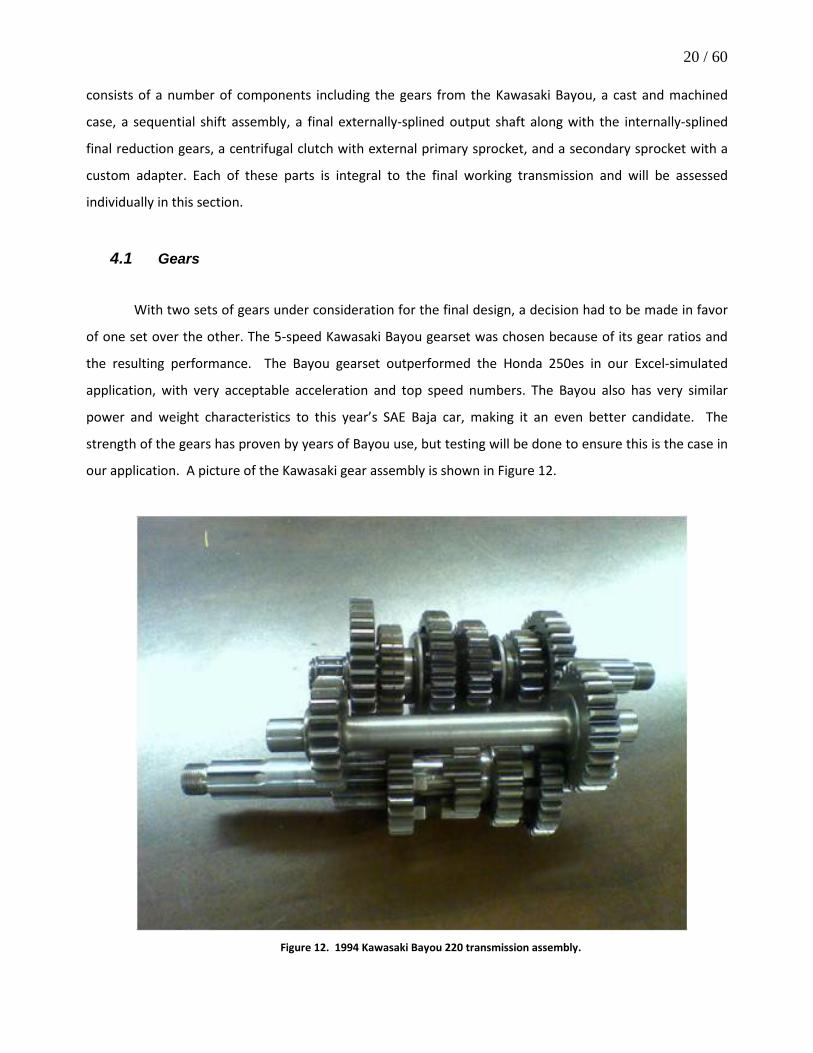
consists of a number of components including the gears from the Kawasaki Bayou, a cast and machined
case, a sequential shift assembly, a final externally-splined output shaft along with the internally-splined
final reduction gears, a centrifugal clutch with external primary sprocket, and a secondary sprocket with a
custom adapter. Each of these parts is integral to the final working transmission and will be assessed
individually in this section.
4.1 Gears
With two sets of gears under consideration for the final design, a decision had to be made in favor
of one set over the other. The 5-speed Kawasaki Bayou gearset was chosen because of its gear ratios and
the resulting performance. The Bayou gearset outperformed the Honda 250es in our Excel-simulated
application, with very acceptable acceleration and top speed numbers. The Bayou also has very similar
power and weight characteristics to this year’s SAE Baja car, making it an even better candidate. The
strength of the gears has proven by years of Bayou use, but testing will be done to ensure this is the case in
our application. A picture of the Kawasaki gear assembly is shown in Figure 12.
Figure 12. 1994 Kawasaki Bayou 220 transmission assembly.

21 / 60
4.2 Case
The design of the case was governed by the packaging of each component of the transmission
assembly: the Bayou gearset, the shifting assembly, the new final reduction gears, and the final output
shaft. Each component in the original Bayou assembly must be located relative to the rest of the parts in
order to maintain proper functionality of the system. To this end, the shafts were located using a precision
spindle probe on a 4th-axis CNC milling center, essentially allowing the mill to provide the same results as a
coordinate-measuring machine (CMM) by accurately locating the centers of each bore as well as the
relative heights of the bore surfaces and outputting the coordinate system relative to the machine’s
absolute origin. Once the relative X-Y coordinates for each bore were obtained with the CNC machine, the
center-to-center distance of these bores was calculated from geometry and plotted in a 2-d sketch within
SolidWorks. It is important to note that for this project, the center-to-center distances of each bore relative
to each other has been maintained, yet the overall orientation relative to a global coordinate system has
been modified to suit the packaging requirements of this project. The final reduction gears, which will be
discussed later in the report, also had to be considered when creating the case shape. To locate the final
output shaft, the pitch diameters were obtained from the chosen gear manufacturer, QTC Gears from
qtcgears.com, and added to the aforementioned 2D sketch for the Bayou components. Once each
component was integrated into the center-to-center sketch, the overall diameters were applied around
their respective center points and then geometric constraints were placed to fully define the location of
each component.
The first constraint applied is the location of the final output shaft relative to the vehicle’s frame.
Recalling that one of the specifications for this project is to minimize any affects of integrating this system
on the other vehicle’s systems, the height and longitudinal location of the output shaft has a direct impact
on the geometry of the vehicle’s driveshafts. Because the vehicle employs an independent rear suspension,
the driveshafts have a 3-piece construction consisting of 2 constant velocity joints (CVJs) and a halfshaft.
Altering the location of the output shaft from the transmission would immediately alter the geometry of
the driveshaft and could adversely affect the power-transmission efficiency of the drive shafts as well as
alter the useable travel of the rear suspension through a mechanical limitation within the CVJs. The second
constraint applied to the transmission components was the location of the bottom plane of the vehicle.
Because the vehicle uses a tube construction, the location of any component of the case must clear the
bottom plane of the car. The final constraint is the orientation of the input shaft. Because of clearance
issues, the engine is installed on the vehicle with the engine output shaft extending to the left, “driver’s”
side, of the vehicle. Logistically, the input shaft of the transmission must then extend to the left side of the

22 / 60
vehicle as well, thereby driving the orientation of the remaining gear trains within the transmission. With
these three constraints, the location of each component of the system is fixed. With all the components
situated relative to each other, the rest of case could be designed around them. The case consists of two
main halves, along with small covers for the shifting components in order to isolate those components from
any foreign objects which could impede their ability to operate properly.
Design for manufacturability was a large concern throughout the entire case design. The curves
and radiuses of the case were designed to coincide with end-mills already in possession in order to reduce
the manufacturing lead time. The mounting tabs were designed in the same way, minimizing machining
passes. Mounting the case would be done similar to last year’s case by utilizing through bolts and
sandwiching the case between two tubes of the rear frame section. For this to work, the lower corners had
to have sufficient material for the bolts to pass through. Bearings and seals required for the various shafts
in the transmission needed to have their bores sized appropriately allowing for a press fit with load bearing
surfaces where necessary. Finally, case thickness was set at 0.25” to ensure it would have sufficient
strength. A full finite element stress study cannot be completed at this time because of the unknown loads
applied to the case by the frame as the suspension cycles.
With respect to the manufacturing process, the overall case dimensions necessitate a stock size of a
minimum of 13” by 9” by 4.5” where the majority of the material of the stock would be cut away due to the
required internal pocket. 6061 aluminum stock of this size was estimated to cost approximately 700 dollars
for both case halves. Due to budgetary constraints and the elimination for any errors to be made, the team
made the decision to pursue casting the case. Casting is a process which suits parts where large amount of
material removal take place for a conventional fully machined part (such as the case’s internal pocket) and
where geometric tolerances do not need to be maintained down to the thousandth of an inch. For this
system, the only features which require a tight tolerance is the relative distances of each shaft within the
case. This then lead to a revised manufacturing plan. Based on feedback from professionals, the case
construction would occur over three phases: lost wax machining, casting, post-machining.
Wax blocks larger than the overall size of the case were created and subsequently machined to the
full dimensions of the case but without a few important features. The mating face between the two case
halves was given an additional 0.375” to allow for the face to be accurately machined flat. Every bearing
bore was not machined into the wax part and any support bosses were given an additional 0.125” minimum
to allow for shrinkage during the casting process. By removing the bearing features and providing extra
material in the wax part, the post machining operation can accurately locate each bore within its support
boss and still retain the minimum necessary wall thickness for strength. One half of the case is shown
below in Figure 13.

23 / 60
Figure 13: Exterior of transmission case CAD model.
4.3 Sequential Shift Assembly
An integral part of the sequential manual transmission is the shift assembly. The unit’s design
translates the lateral hand movement from the driver into the angular movement needed to rotate the
shifting cam and shift the transmission either up or down. Without the assistance of an automatic clutch,
the shift lever as well as the linkage will need to be strong and rigid enough to withstand the abuse of
power shifting the transmission. The assembly will also need to be lightweight and cost effective in order to
incorporate it into the final design of the transmission
Dynamic analysis was used to determine the length needed for the shift lever as well as the force
exerted by the driver. A digital force transducer was acquired and used to measure the actual force needed
to shift through the gears of two modern quads. The first quad that was tested was a Honda 250 which
gave a maximum shifting force of 11.8 pounds. The Honda’s lever was 8 inches in length so the maximum

24 / 60
torque needed to shift the Honda was 94.4 lb-in. The second quad that was tested was a Yamaha Raptor
which gave a maximum shifting force of 12.2 pounds. The Yamaha’s lever was also 8 inches in length so the
maximum torque needed to shift the Yamaha was 97.6 lb-in. An average of about 96 lb-in was taken from
both and applied to the Kawasaki Bayou. The diagram of the shift linkage kinematics is shown in Figure 14.
Figure 14: Lengths of rod setup used for the travel calculation as well as the force calculation.
The torque needed to rotate the shift cam of 96 lb-in was first divided by the length of the shift cam
lever (3.0 inches) and equated to a force seen by the spherical rod end of 32 pounds. This force was
translated to the bottom of the shift lever through the rigid rod and the other spherical rod end. With the
shift lever free to rotate on a pin, the force of 32 pounds was translated to the top of the shift lever by
multiplying the force by the bottom length (2.5 inches) and dividing by the top length (4.0 inches). The
force seen by the driver’s hand was calculated to be a maximum of 20 pounds, which is reasonable for the
driver to handle.
Dynamic analysis was also used to determine the travel of the top of the shift lever. The length of
travel from both quads mentioned above with the 8 inch arms was measured to be 2 inches. Reducing the
arm down to 3.0 inches also reduced the travel to 0.75 inches. The diagram of the travel kinematics is
shown above with the force kinematics. The travel of 0.75 inches is translated through the solid linkage to
the bottom of the shift lever. Then through similar triangle geometry (T3 = 4.0*(0.75/2.5)), the travel at the
top of the shifter is calculated to be 1.2 inches. This travel is practical for a short throw shifter on a
sequential assembly and interconnects well with the transmission system.
A buckling analysis was also completed on the rod to find the minimum allowable rod diameter. A
schematic of the buckling analysis is shown in Figure 15. Equation 1 defines the buckling of a rod.
(1)
3.0 in.
4.0 in.
2.5 in. T1=0.75 in.
T2=0.75 in.
T3=1.2 in.

25 / 60
The maximum force applied to the rod was approximately 32 pounds and with a factor of safety of 2.5, Fcrit
is 80pounds. This value for Fcrit is a much greater force than the rod would ever see in its lifetime. The
elastic modulus, E, for low carbon steel is 30x106 psi, the length of the rod, L, is 27 inches, the second
moment of area, I = , the value K is 1.0 for a rod fixed at both ends but free to rotate. Solving for the
diameter results in Equation 2,
(2)
and assessing all the values given yields a minimum diameter of 0.106 inches. This value is well below the
0.375 inch rod selected for the shift linkage, so the linkage will prove to be extremely rigid which is needed
for the setup without the automatic clutch.
Figure 15: Applied forces on the rod used for the buckling calculation.
The cable linkage was compared to the rod linkage by analyzing total part number, cost, weight,
routing, and rigidity of each assembly. Although the solid rod linkage contains slightly more parts than the
cable linkage, the advantages of the rod linkage are its weight and cost. The other advantage of the solid
rod linkage is the rigidity of the setup. The driver needs to have a feel for the gear mesh in the gearbox
without the accommodation of an automatic clutch and the only way to achieve this is through the solid
rod linkage. The only disadvantages of the solid linkage are the limited routing options for the setup and
the possibility of the linkage catching on debris on the course, which are both advantages of the cable
linkage assembly. The analysis for the two setups is shown in Tables 4 and 5.
Fcrit

26 / 60
Table 4: Sequential Shift Assembly Analysis (Cable Linkage)
Sequential Shift Assembly Analysis (Cable Linkage) Qty Part Material Cost ($) Wgt (lbs) Notes
1 Shift Lever Aluminum 6061 14.28 1.15 CNC (2.125in dia bar) 1 Shift Lever Pivot Pin Aluminum 6061 2.40 0.02 3/8 in bolt 2 Mounting Tabs Steel 4340 3.82 1.24 Laser cut and drill(.125in plate) 1 Shifter Cable N/A 42.99 0.25 B&M heavy duty cable (3',4',or 5') 1 Gusset Plates Steel 4340 20.72 0.23 Laser cut (.125in plate) 2 Torsional Spring Spring Steel 2.22 0.05 Order from Centuryspring.com 2 Cable Tabs Steel 4340 2.00 1.00 CNC from .25in thick steel
**Metal from www.metalsdepot.com Total Cost: $88.43 Total Weight: 3.94 lbs Total Parts: 10
Table 5: Sequential Shifter Assembly Analysis (Rod Linkage)
Sequential Shifter Assembly Analysis (Rod Linkage) Qty Part Material Cost ($) Wgt (lbs) Notes
1 Shift Lever Aluminum 6061-T6 14.28 1.15 CNC (2.125in dia bar) 2 Mounting Tabs Steel 4130 3.82 0.32 Laser cut (.125in plate)
3 3/8" Hex Bolt w/ nut Steel ASTM Grade
A 1.00 0.10 Length of bolt will vary 2 Gusset Plates Steel 4130 20.72 0.23 Laser Cut (.125in plate) 1 Torsion Spring Spring Steel 6.20 0.07 Torsion Shift Spring from Bayou 1 Torsion Spring Bushing Aluminum 6061-T6 0.00 0.07 Lathe/Drill (1.25in dia bar) 2 Spherical Rod Ends Steel 4130 10.00 0.26 Female (RH and LH) 1 Rod Low Carbon Steel 6.05 0.30 3/8in thread with L=28.5in 1 Cam Shaft Support Steel 4130 5.00 0.25 Laser cut and drill (.125in plate) 1 Pivot Bushing Aluminum 6061-T6 0.00 0.01 Lathe/Drill from .75 in dia bar 1 Shift Cam Lever Steel 4130 7.66 0.30 CNC (.125in plate)
**Metal from www.metalsdepot.com Total Cost: $74.73 Total Weight: 3.06 lbs Total Parts: 16
The manufacturing of the sequential shift assembly with the rod linkage is particularly
straightforward. A select few parts do require machining while the others will be sourced. The hardest part
from the assembly to machine will be the shift lever. The handle will be turned down on the lathe and a

27 / 60
fourth axis CNC milling center will be used to create the remaining features. The mounting tabs, gusset
plates, shift cam lever, and cam shaft support will be plasma cut and ground down from 1/8 inch plate. The
holes on the mounting tabs, shift cam lever, and camshaft support will then be drilled using a drill press.
The outer diameter of the pivot bushing as well as the torsion spring bushing will be turned down using a
lathe and the inner diameter will be drilled using the drill press. The hex bolts, torsion spring, spherical rod
ends, and rod will all be ordered online from a few specified websites.
The rod linkage proves to be the best design choice for the project. The advantages of the solid
linkage setup far outweigh the cable linkage setup. The rod linkage is $13.70 cheaper and almost a full
pound lighter than the cable linkage setup. The rod linkage will also provide the rigidity needed without the
use of the automatic clutch in the manual transmission. The calculations performed above show that the
parts chosen for the setup will work effectively. The part drawings as well as the assembly drawing and bill
of materials can be found in Appendix F.
4.4 Final Output Assembly
The final output assembly contains the majority of the parts to be manufactured by our team, aside
from the case. A CAD schematic of the assembly is shown in Figure 16, cost in Table 6. BOM can be found
in Appendix F.
Figure 16. CAD schematic of output assembly. The floating gear is splined to the Kawasaki output shaft.

28 / 60
Table 6. Output assembly cost.
The shaft is stepped in two places to accommodate the gear and bearing shoulders. The material
will be 4140 steel, to be splined with a two separate "cutters" from mcmaster.com. The first spline will
apply to both ends, matching the dimensions of the CVJ's to which they mate. The second spline is slightly
larger (arbitrary dimensions) to fix the 54 tooth gear. Snap ring grooves will be machined in the
appropriate locations to fix both bearings and the gear. The gears will be purchased from qtcgears.com,
material analogous to Grade 4 AISI 1045H steel.
The gear splines have presented a significant manufacturing challenge. The internal spline on the
18 tooth pinion requires a spline broach of exact dimensions: those of the male Kawasaki splined output
shaft. The "Advanced Adapters" company located in Paso Robles, has assisted in extracting the dimensions
of this spline using a precise measurement device and a reverse engineering technique. The spline is
standard but rare, requiring the broach of a third party such as "Tilton Racing." The "Clutchnet Corporation"
in El Monte, CA, and the locally owed "Muller Machine" provided the internal splines cuts for the 18T
pinion, and 54T gear, respectively.
The second more complicated approach is to modify the existing Kawasaki bevel gear that was
originally splined to the Kawasaki output shaft. The hub of this gear can be removed, and itself splined to
be used as an "adapter" for the QTC gear. Either method meets the design requirements, and if necessary
the second approach can be realized by future teams. Significant analysis needs to be completed on these
components, discussed later in this document.
4.5 Clutch Assembly
As our research continued and the decision was made to run a Bayou gear set, the clutch setup had
to be decided on. From the factory, the Bayou quad uses both a centrifugal clutch and an automatic clutch.
For this project, the vehicle will also integrate a centrifugal clutch, though sourced from a separate supplier,
in order to eliminate any possibility of stalling the vehicle. Performance centrifugal clutches are extremely

29 / 60
common in go-karts, however most of the models available use a smaller number 35 chain. Our car needed
to use a number 40 chain to survive the driving situations the Baja car will see. Fortunately, the Briggs and
Stratton engine used in the vehicle is a standard dimension used on many go-kart applications. The final
clutch to be used is a Noram 1600 series. This clutch is easily "tuneable" and also fits the specifications set
forth for chain size, engine interface and engagement speed. The larger sprocket option was chosen for
maximum strength and for optimum reduction, and the standard engagement of 1800 rpm selected
matches the engine’s idle speed of 1750 rpm. Bench testing will ensure the clutch engages properly, and
springs and weights can be adjusted accordingly should the need arise.
The automatic clutch functions similar to a normal, manual clutch but the difference, however, is
that the auto clutch is engaged and disengaged by the shifting mechanism itself. What this does is allows
the gears to be shifted easily with minimal input from the driver. This feature would improve the vehicle’s
drivability and aid the team’s sales presentation and potentially aid the “Originality and Innovation” portion
of the design judging. The actuation of the auto clutch is somewhat complicated, however. The clutch itself
consists of a basket with an input gear, clutch packs inside that basket, and the internal “cage” that acts as
the output of the clutch. The outer basket and internal “cage” are connected by four bolts and four springs.
The action of the springs pushing out applies pressure to clutch packs, thus engaging the clutch. To
disengage, a lever arm applies a force to the inner “cage” and compresses against the springs, ultimately
relieving pressure from the clutch packs. Lastly, the entire clutch system is encased and operated in oil. The
concept is fairly simple, but the implementation of the system is exceedingly complex.
The automatic clutch was ultimately removed from the design. Considering the time allotted to this
project eliminating the auto clutch allowed the team to rapidly move forward and ultimately resulted in the
full design being completed within hours of the decision being made. Before completely committing to the
idea, all possible driving situations were analyzed to ensure the car would not stall and retain its
performance characteristics. Fitting the drive chain and the lever arm that engages and disengages the
auto clutch was not spatially possible without designing a whole actuation mechanism or drastically
changing our sprocket size and ratio as well as the case. Because the auto clutch is designed by Kawasaki as
a wet clutch it became apparent that encasing the clutch, delivering oil to it, and simultaneously sealing the
chain would have required an extremely elaborate outer case that, again, just was not feasible in the time
frame of this project.
The primary consequence of this decision is that shifts will not be as easy, however many race
quads and bikes are successfully shifted with no clutch. As mentioned before, the system will be bench
tested to verify this and determine what kind of driver training may be necessary.
30 / 60
4.6 Secondary Sprocket and Adapter
The initial connection between the Briggs motor and the gearbox consists of a sprocket on the
centrifugal clutch leading down to a larger sprocket down at the input of our gearbox. The sprocket chosen
to work with the 14-tooth unit on the centrifugal clutch was a 40-tooth, for a reduction of 2.86 : 1. This
ratio coupled with the final reduction of 3 : 1 optimizes the performance of our car as characterized by a 0 -
100 feet acceleration run and the vehicle’s top speed. With the removal of the auto clutch, mating the
sprocket to the Bayou input shaft is accomplished by utilizing an adapter to mate to the shaft’s splines. The
adapter design is comprised of a flange with the sprocket bolt pattern fixed to a hub with the female
counterpart of the coarse 6-spline pattern on the Bayou input shaft.
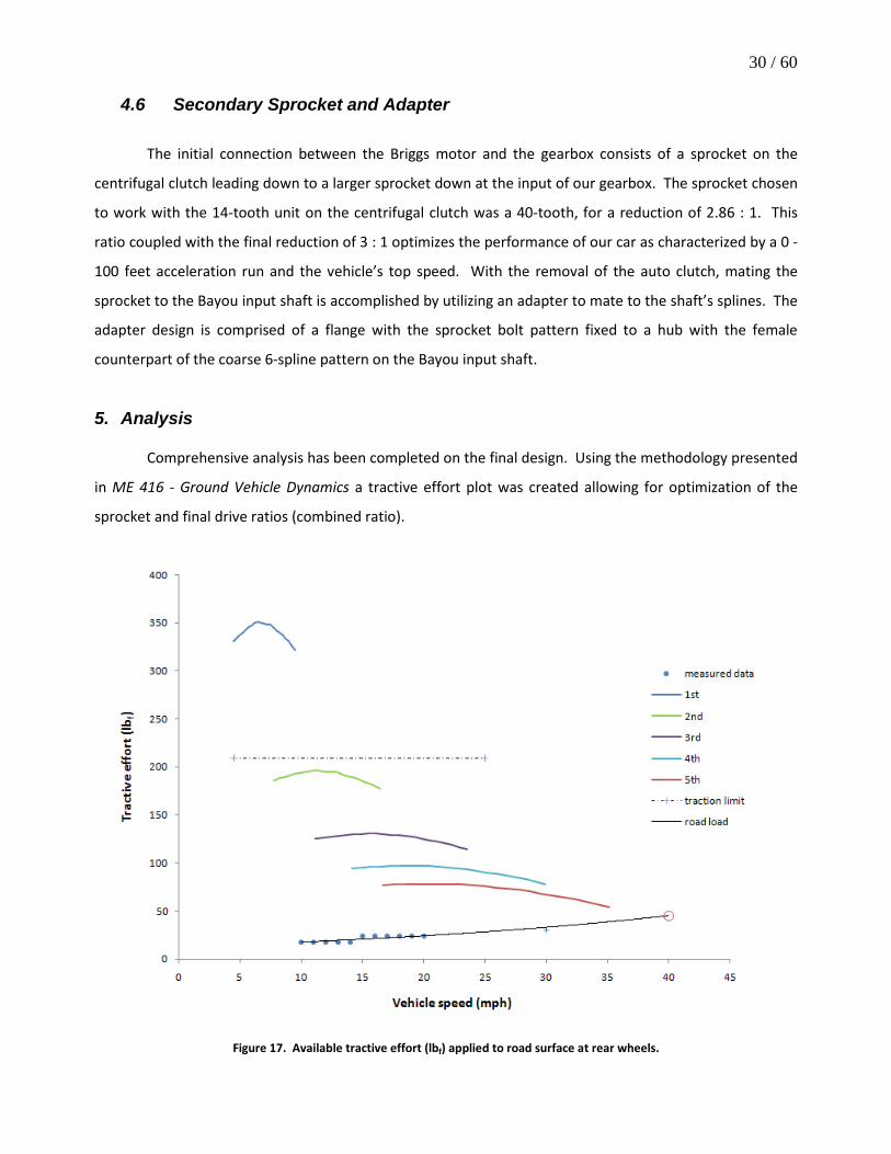
5. Analysis
Comprehensive analysis has been completed on the final design. Using the methodology presented
in ME 416 - Ground Vehicle Dynamics a tractive effort plot was created allowing for optimization of the
sprocket and final drive ratios (combined ratio).
Figure 17. Available tractive effort (lbf) applied to road surface at rear wheels.

31 / 60
The 9 : 1 ratio was selected to achieve a desired balance between acceleration and time to top
speed, as these two performance characteristics are the team's primary concern. A road load curve was
extrapolated from experimentally obtained data and representative curves from the literature. The
traction limit was derived using a Newton's Law FBD to obtain normal force on the rear wheels, and the
assumption of f =0.7 for the road surface. These results are shown in Figure 17. Figure 18 further
illustrates the effect of combined aerodynamic drag and road resistance as speed increases. Because the
engine is severely power limited this effect becomes significant at speeds above 20 mph.
Figure 18. Power loss due to combined aerodynamic drag and road resistance.
5.1 ADAMS - Rigid Body Dynamic Simulation
The dynamic simulation software ADAMS was used to analyze two failure modes. The first is a
verification that the vehicle can accelerate on a 45° incline (rock crawl event). The critical location for this
scenario is the 13 tooth pinion on the Bayou input shaft. A resistive torque is applied to the output shaft
using a step function to emulate a realistic gradual torque increase. As the majority of the components in

32 / 60
the assembly are not transmitting power, they are omitted to simplify the model. This scenario is depicted
in Figure 19.
(a) (b)
Figure 19: ADAMS model (a), force and torque vectors during simulation (b).
The ADAMS results indicate a maximum tooth force of 815 lbf for the first gear incline condition, an
acceptable magnitude with respect to the material yield strength. A vibration study on this scenario was
also completed. Eccentricity in the tooth form is the most common manufacturing error in gear
production. The red tooth in Figure 19 has been given a slightly larger pitch tooth thickness, and the input
shaft initial conditions represent the engine at its engagement of 1800 rpm. Gear mesh frequency for this
pair becomes very evident when this eccentric tooth mesh is modeled in ADAMS.
Figure 20. FFT spectrum for 1st gear engagement with an eccentric tooth on the bayou input pinion.

33 / 60
Each tooth force creates a unique relatively small magnitude frequency, while the force generated
by the eccentric tooth is quite large. This condition will accelerate wear in the mesh, as well as contribute
to "chatter" noise. Backlash is automatically simulated in the ADAMS environment due to the nature of the
contact force algorithm. The frequency sidebands are due to this modeled backlash. The FFT spectrum
results are shown in Figure 20. A second critical condition is the vehicle landing from a 10ft. height at top
speed. This is the worst case scenario that the transmission components will ever experience. A
"translational slider" is the critical location in the Bayou assembly, and experiences a more complicated
shock torque than the previous case. As the vehicle touches the ground and the air shocks depress, a
normal force equivalent to 3.16 g's acts on the rear axle. This causes a rapid increase and then decrease in
resistance torque, shown in Figure 21.
Figure 21. Shock torque applied to output shaft as vehicle lands from a 10ft. height at top speed.
While this analysis has been helpful for the team's conceptual understanding, it must be extended
to include the components of our final drive assembly to be useful. In this situation a safe assumption is
that the critical locations will occur on our manufactured driveshaft components, either on the 18T pinion
or 54T gear teeth, or the shaft splines. An analysis has been completed using both AGMA methodology and
the Lewis-bending equation, results shown in Table 7.

34 / 60
5.2 Stress
Table 7. AGMA and Lewis-bending results.
The AGMA equations are for bending and contact stress (wear) for infinite life, which is not a
priority of this project. The Lewis-bending approach contains larger uncertainty but is more appropriate for
this design. The conditions for the AGMA analysis are for torque produced by maximum tractive effort (209
lbf), occurring in 2nd gear, with engine speed constant at 2700 rpm, at 99% reliability. The transmission can
operate under these conditions for >107 cycles at the indicated safety factors. σmax occurs when the vehicle
lands from a 6ft. height, resulting in a torque magnified 2.44x at the same engine speed in 2nd gear. The
Lewis-bending results indicate that all critical locations have SF > 1, except for the splines at σmax. "Shigley's
Mechanical Engineering Design" is known to be conservative, and not necessarily applicable to automotive
transmission gears. These results appear reasonable, details provided in Appendix E.
Figure 22. Overlapping force profiles indicate the load sharing of the contact ratio.

35 / 60
Investigation into the effect of a damaged or broken tooth reveals several interesting aspects of a
meshing spur pair. The contact ratio becomes evident when the force experienced by each tooth is
superimposed on one plot. The magnitude of the force on the teeth immediately following the damaged
tooth is drastically increased, shown in Figure 22. A transmission with a broken tooth is in grave danger of
catastrophic failure, as several teeth are carrying loads far greater than the intended design load.
6. Product Realization The original project timeline for product realization follows,
• Case
o Cast aluminum
o Machined surfaces and bearing surfaces using CNC milling center
o Bearings pressed
o Holes drilled and tapped where necessary
• Sprocket Adapter
o Turned down from solid disk of aluminum
o Holes drilled
o Material removed using mill to reduce weight
• Final Output Shaft
o Turned down on lathe
o Cut grooves for retaining rings on lathe
o Cut splines using 4-axis CNC milling center
o Heat treat
• Shift Assembly
o CNC’d from aluminum block
o Partly turned down on lathe
o Holes drilled
o Section for linkage removed using mill
o Weld on various tabs
• 18T Spur Gear
o Anneal old Bayou bevel gear
o Turn down bevel gear to hub

36 / 60
o Machine groove(s) for key(s)
o Bore out 18T gear
o Machine for key(s)
o Turn down end of shaft for bearing
o Heat treat
–OR–
o Broach 18T gear for 18-spline Bayou shaft
o Turn down end of shaft for bearing
o Heat treat
6.1 Sprocket Adapter
The sprocket adapter is constructed from two components, shown in Figure 23. The first
component is sourced directly from the OEM Kawasaki automatic clutch cage. From the manufacturer,
Kawasaki employs a cast steel center which has the female six-spline pattern that corresponds to the
transmission’s input shaft.
Figure 23. Completed sprocket adapter.

37 / 60
This piece is cast as a cylinder with 4 external bosses and the splines are post-machined to obtain
the required fit. Because the input shaft’s spline pattern is extremely difficult to replicate, either in-house
or outsourced, the steel center section from the automatic clutch had to be reused. The second component
of the sprocket adapter is a one-off piece manufactured from 4140 alloy steel. The stock selected was a 6
inch round by 1 inch thick 4130 steel disk.
The main body of the adapter is created using a three axis computer numerically controlled (CNC)
milling center. The first operation is to create soft jaws to accommodate the stock size by cutting a 5.98”
diameter hole 0.125” deep into aluminum jaws. The 20 thousands diametral offset is to allow the soft jaws
to have a strong clamping force on the stock in a similar fashion as an interference fit functions. If the
diameter that is cut into the soft jaws was the same dimension as the stock size, the disk would essentially
float in the jaws and is then liable to be thrown by the cutting forces of the endmill. Further, the 5.98”
diameter implies that the aluminum jaws must be greater than three inches thick. Realistically, smaller
aluminum jaws can be used if the vise jaws are cut with enough separation such that a smaller percentage
of the actual 5.98” diameter is visible per jaw. The second operation is to mill the first side of the stock
creating the cylindrical center section, the interference fit bore in the center of the part, and the weight
reduction pockets on the outer face of the part. This entire setup can be achieved with a single 4-flute ½”
endmill.
Figure 24. Spline adapter being pressed into the main body of the sprocket adapter.

38 / 60
The spline adapter piece, because of the external bosses, is only retrievable by fracturing the
aluminum cage. The bosses must then be removed so that the remaining part is a smooth cylinder with the
6-spline internal feature and an 1/8” thick larger diameter flange. Once the first setup is completed and the
spline adapter has been machined to the proper dimensions, the spline adapter can be pressed into the
main body. An image of this process can be seen in Figure 24.
Because of the nature of the load being applied to this part, a weld was applied to the joints where
the spline adapter surface met the main body to ensure that the splined inner part does not break free of
the interference fit within the main body. Because the spline adapter is likely a low alloy steel, the assembly
was pre-heated to 350 degrees Fahrenheit prior to welding to allow for adequate penetration and proper
molecular bonding of the materials. Once the welds were completed, a post-weld heat treat at 1550
degrees Fahrenheit with air cooling was conducted to normalize the assembly in order to relieve local
stresses caused by the welding and in order to improve the machinability of the assembly.
The assembly is then taken back to the CNC milling center and the soft jaws are re-used to clamp
the piece from the previously machined surface. A second program is then run to face the second side of
the sprocket adapter flat and drill the hole pattern required to bolt the 41 tooth sprocket to the main body
of the adapter. Careful attention must be given to the orientation of the weight reduction pockets relative
to the machine’s coordinate system to ensure that the bolt holes are located between the pockets and not
between the outer surface of the part and the beginning of the pocket. At the end of this program, the
sprocket adapter is completed.
6.2 Shift Lever The shift lever is a complicated part which requires the use of both a four-axis CNC milling center as
well as a CNC lathe. The stock purchased for this part is a 2.125 inch diameter by 1 foot solid round bar of
6061 Aluminum. The first operation for the shift lever is to load the stock directly into the CNC lathe as
supplied. The handle potion of the lever is then machined to the designed dimension with a simple facing
operation to create the flat top portion and then turning down the stock to size. The CNC’s supplied quick-
code operations can then be used to create the negative fillets which transition the handle section of the
lever to the lower square body. A very skilled and experienced machinist could likely do this section by
hand, thereby eliminating the need for a CNC lathe. The part can then be parted off to within a quarter inch
over the final overall length of the part. The remaining material will be machined off in a later operation.
The second operation employs the 4-axis machining center. For this part, a 3-axis CNC milling
center was fitted with a 4th axis chuck which connects to the machine’s controller. The part from the first

39 / 60
operation is loaded into the 4th axis with the handle section providing the clamping surface. Regrettably,
the surface finish of the handle will be affected by this setup. A program can then be run to create the
remaining features of the lever including: the flat surfaces 90 degrees from each other, both through holes,
the pin hole, the curved end sections, and the open end pocket. The tools required to complete this
program are a ½” endmill, a #3 center drill, a 3/8” drill, and a #25 drill. With a 3 flute carbide endmill with
approximately 1.5 inches of stickout, the program has an estimated machine time of 13 minutes.
6.3 Covers The OEM configuration of the powerplant as supplied by Kawasaki employed 4 cases to completely
house the drive components of the Bayou. Because of this, the final design for this project employs two
primary aluminum cases which house the gears, shafts, bearings, seals, and a portion of the shifting
mechanism, and two external covers to shield vital components from foreign object damage and
obstruction. The first cover is constructed from ultra high molecular weight polyethylene (UHMW PE) and
functions as a shield for the moving parts which control the sequential shifting mechanism of the Kawasaki
gearset. The second cover is a flat acrylic cover which protects the reverse lockout mechanism and the
electrical switch for the reverse and neutral lights from foreign debris. These covers do not require a high
strength material because the location of the transmission within the Baja vehicle is such that the assembly
is protected by the frame members and suspension components. However, in case of any unforeseen
circumstances, these components are simple, quick, and cost-effective to manufacture.
The shift mechanism cover is constructed from a 6” by 6” by 0.75” square block of UHMW PE. The
entire part can be created in one setup on a 3-axis CNC milling center. The block is held with a standard vise
and the program can be run using the following 3 tools: 3/8” endmill, a #3 centerdrill, and a #12 drill bit.
Because plastic is a soft material, the feed rates of the tools can be raised above that of aluminum and the
part has an estimated runtime of 8 minutes and 37 seconds.
The reverse lockout cover is created using a rectangular bar with dimensions of 1/8” thickness by 3”
width and 4’ of length. The unusually long bar is as supplied and can be cut down to more manageable
pieces. The entire part is created using a laser cutter. The sketch of the cover, including every hole, is
exported from Solidworks to a *.pdf file and is opened with Adobe Illustrator on the laser’s attached
personal computer. Because the laser essentially functions as a printer, the settings for power and speed of
the laser are controlled directly from the “printer” settings within Illustrator itself. It is important to ensure
that the line stroke of the sketch is set to 0.01 pt in order to allow the laser’s processor to interpret the
sketch as a series of vectors rather than an image. This will allow the laser to follow the lines directly rather
40 / 60
than performing a raster cycle similar to a conventional printer. While the final part quality may not be
affected by this setting, the part’s total runtime is tremendously decreased by using the thin line stroke.
The laser settings used for this part are a power of 100, speed of 7.5 with PPI set to 500. This required two
runs. In order to create the part in a single pass, the speed of the laser can be slowed, however this will
create higher heat within the acrylic and could result in a very poor edge.
6.4 Output Shaft
This section refers to the final output shaft for the system which protrudes outside of the case and is used
to drive the vehicle’s drive shafts. The output shaft is created from a 1 ¼ “ diameter by 1 foot long solid
piece of 4130 steel bar stock. The first operation is to face the bar to length. The next operation is to turn
down the diameters of the two end sections of the steel to 1” in order to create the required OD for the CVJ
splines. Once in this configuration, the part can be setup in the 4th axis chuck on a CNC milling center. Extra
care must be taken to ensure the part offsets are established correctly for each axis in order to create equal
splines around the entire part. Failure to do so will result in thin spline teeth and will result in part failure. It
is advisable to run the program for the spline pattern with conservative cutting speeds and depths in order
to minimize part deflection within the chuck. It is important that this manufacturing operation is not begun
until the internal splines on the final reduction gears have been created in order to verify that the splines
on the output shaft will match the gears (depth, width, etc). Once the part has been removed from the 4th
axis chuck, it will be nearly impossible to re-establish the offsets to ensure that the program cuts in the
same locations as before.
The final operation for the output shaft is to groove the center portion of the shaft to accept the
retaining rings to locate the 55 tooth gear. A custom thickness parting tool must be ground to
approximately 10 thousandths over the thickness of the retaining ring. In a manual lathe, the custom
parting tool can be used by incrementally cutting the groove and checking for proper fit with the retaining
ring. A groove that is not deep enough will not allow the retaining ring to seat properly and a groove that is
too deep could potentially allow the gear to slip over ring. A picture of the completed output shaft can be
seen in Figure 25.

41 / 60
Figure 25. The final output shaft contains both gear spline and CVJ spline profiles.
6.5 Gears The gears were purchased as blank stock items from "Quality Transmission Components." They
came with a smooth central bore and a hub extrusion on one surface. Because of this, the gears must be
modified to accept the new splines from the Bayou gearset and the output shaft. The hubs on the gears can
be removed by running a simple facing operation on the mill, fixturing by the lower surface of the gear with
toe clamps. The next operation is to bore out the center hole in both gears to the required dimension as
specified by the broach manufacturer. Aluminum soft jaws can be used to fixture the gears in the mill. For
these gears, a CNC milling center was used to create the center bore and to machine out the webs in the
larger gear. An excessive wall thickness was used without FEA verification on the gear webbing in order to
retain a large amount of the tooth strength while removing much of the gear’s initial weight.
Once the bores for each gear has been created, the internal splines must be cut. Ideally, internal
splines can be cut with a broaching machine. However, because of the high cost of broaching tools and the
unusual spline pattern as required by the Kawasaki gearset, an external source was used in order to wire

42 / 60
EDM cut the pinion gear’s splines while another supplier was used to cut the spur gear’s splines with a
broach. A final assembly of the 55 tooth spur gear mated to the output shaft can be seen in Figure 26.
Figure 26. Quality Transmission Components 55T gear mated to the final output shaft.
6.6 Cases
The main case halves of the manual transmission are the largest manufacturing obstacle for this
project in terms of both complexity and cost. Because of the nature of a gear reduction system, the
dimensional tolerances which locate the centers of the gear shafts are extremely critical and necessitate
the use of high accuracy manufacturing methods. For this iteration of the case halves, two routes were
pursued: investment casting and fully machining.

43 / 60
Investment casting is a process in which the net shape of the part is created from, in this case,
machineable wax (clay, plastic, and a select few other materials may be used) and is then set into a metal
flask. Once located within the flask, plaster is poured around the wax mold within the flax and is allowed to
cure. The wax is then melted out and the result is a cavity within the plaster of the net shape of the final
part. Molten aluminum is then poured into the cavity and is allowed to harden and after a set time period,
the plaster is broken away leaving the final part. The advantage of this process is low cost (due largely to
the donation of time and plaster by Martin Koch of the IME department). The disadvantages of the process
are longer lead times, low overall dimensional accuracy, and difficult setups.
The second method requires a single billet block of aluminum and is therefore a much more
expensive option. However, because the process begins with the aluminum piece, machining the halves
inherently requires fewer steps to achieve final shape than investment casting. Also because the entire
halves are created using a CNC milling center, high accuracy can be obtained. For this method the full CAD
model is uploaded into computer aided manufacturing (CAM) software such as CAMworks (an add-on to
SolidWorks) and the CNC milling center’s tool paths are generated through the software. The software can
then translate three-dimensional tool paths into the machine’s language, G-code. The aluminum billet can
then be taken to the CNC mill and the tools and the stock must be correctly loaded into the machine. Once
the full setup is completed by the operator, the machine can be run to yield a complete first setup. This
process must be repeated for each setup.
6.6.1 Investment Casting
The wax mold for the investment casting process was created in a similar fashion to a full aluminum
part by using CAM generated tool paths with a CNC mill. However, because wax is a much softer material
the machine’s spindle speed and feed rates can be increased significantly to reduce operation times. Prior
to machining, though, the wax blocks must be prepared by manually machining both the top and bottom
surfaces and a single edge to be flat in order to establish datum planes which can be used to set the future
CNC program’s coordinate systems accurately and square within the axes of the machine. In order to allow
for the wax to be aligned correctly for the second setup (to be discussed later) two 9/16 inch diameter
holes must be drilled through the entire stock at the top two corners. It is recommended that the manual
preparation of the wax block be done by manually operating the CNC mill. This allows for the block to be
accurately aligned and set within the machine once the side has been cut flat provided that the operator
does not remove the clamps. Figure 27 shows an image taken while the first CNC program is running. It
shows the machined flat edge (note the edge is not machined to the full depth of the part, this is sufficient)

44 / 60
and one of the two drilled locator holes. The coolant on the top of the wax covers the top flat surface, but
both the top and the bottom were machined flat (with respect to each other) by a fly cutter endmill.
Figure 27. Image of the Haas CNC milling center during its first operation on the first setup.
Note the clamping system used and the machined flat datum points. Once the initial preparation has been completed, the first program for setup 1 can be run with the
toe clamps located, shown in Figure 27. Due to flask limitations when the wax stock was being poured, the
first program necessitated the inclusion of multiple program pause codes (m00) to allow the operator to
move the toe clamps to a new location, clear of the remaining tool paths. The stock can then be flipped
over and aligned with a dial indicator for the side two operations. The first setup cuts the internal features
of the case, excluding the bearing bores, while the second setup will cut the external features including the
seal bolt profile but excluding any through holes.
Because the wax will be used for an investment casting process, through holes on the mold are
removed because there is no guarantee that the holes will result in smooth bores once casting is complete.
The hole profile might not be circular, the bore would have an unacceptable surface finish, and the bore
could not be straight. Because every hole, blind or through, is critical for component alignment, it was
decided to leave the bores for the post-machining phase.

45 / 60
Once the aluminum case half is retrieved from the plaster, the post machining process can begin.
The first step is to remove the downsprues and the gating system from the part. The sprues can be
removed roughly with a bandsaw and finished down to their final depth with the milling program and the
gating system can be removed in a similar fashion. Figure 28 is an image of the aluminum casting
immediately after it was removed from the plaster.
Figure 28. Aluminum case half immediately after removal from the plaster.
Unfortunately, full post machining of the bearing surfaces could not be completed because of a
number of failures with the casting process. The first difficulty was uncovering the true shrinkage rate of
the specific process being used. For investment casting, the general rule of thumb is 2% shrinkage. This
means that the wax mould should be enlarged by 2% throughout the entire part in order to yield a casting
which is dimensionally correct. However in this iteration, the aluminum casting was never created within an
acceptable tolerance. The result being that the location of the bearing bores within their support bosses on
the case half were located incorrectly. In some cases the bores were non-concentric with the boss and
created a small wall thickness on one edge, in other cases the bores would miss the boss completely and
create a zero-wall thickness condition. These incorrect placements are a result of the excessive shrinkage of

46 / 60
the casting creating an overall smaller part than designed and because the datum point for post machining
was a square corner located on the external profile of the case, the bores resulted in locations which
required scrapping the casting. Ultimately, the lead time per casting and the required time to be invested in
order to yield a correct part were deemed to outweigh the cost of purchasing two solid pieces of billet
aluminum and switching the manufacturing method to fully CNC machining.
6.6.2 Full CNC Machining
As previously discussed in the methodology overview, fully machining the case halves requires the
use of a 3 axis CNC milling center. Because of the nature of the project’s budget and timeline, extra care
must be taken in preparation prior to the start of cutting the expensive pieces of aluminum. Specifically,
tool selection, setup orientation, and operation list must be carefully selected and organized in order to
minimize chatter, tool breakage, tool wear, operation time, part vibration, and accuracy. Full details and
description of the methodology behind the generation of each individual tool path and the setup design will
be omitted from this report due to the often dynamical nature of the process. For reference purposes only,
machining "setup sheets" are provided in Appendix G. For further iterations, an experienced machinist
should be consulted for proper tool path generation and setup selection.
For strength and machinability, the alloy selected for the case halves was 6061-T6. However, while the
alloy itself is classified as machineable, because the design of the case incorporates an approximately 4”
internal cavity (varies per side), standard cutting tools will not suffice. For this iteration of the case halves, a
standard ¾” diameter, two-flute, high speed steel (HSS) endmill was used with a 4 inch length of cut for the
internal cavity of the case. Because of the stickout required to clear the part when milling the deepest
section of the cases, rigidity of the tooling was adversely affected, causing high amounts of tool vibration
and resulting in excessive tool wear and undercut bearing bores. Additional research into high-rigidity
cutting tools led to carbide insert end mills such as those shown in Figure 29. These tools incorporate a solid
metal shank with carbide inserts at the tips and allow for deep tool paths and high chip loads (0.008
in/tooth instead of 0.002). They also allow for easy upkeep should the carbide inserts exhibit excessive
wear or crack. Further, the shanks are available in a wide range of diameters to suit the corner radii and
tight confines of the case. The disadvantage is a high initial investment.
For the remaining features, when possible, full carbide three-flute endmills were used to allow for
greatly increased feed rates and spindle speed in order to reduce operation times. It should be noted for
future operators that the largest diameter endmill that can be used for each feature should be used in
order to reduce tool chatter.

47 / 60
Figure 29. Example of carbide insert endmills from http://www.sandhogtools.com/en/products.
Setup selection and the operation order can significantly affect the quality of the part. Because of
the large cavity, the single wall which houses the bearing and seals is easily affected by the cutting forces of
the end-mill and if left unsupported will vibrate causing an undesirable surface finish and a locally non-flat
surface. For this iteration, the internal cavity and external profile were cut in the first setup which removed
a large portion of the material, yielded a part which was close to the final shape, and yielded a machined
flat surface with which to setup side 2. However, the back side of the case halves would resonate when
being cut. Further investigation into setup design and the cut order for the features would be valuable in
order to improve the accuracy of the features by reducing tool chatter and part vibration.
Feature accuracy is an important factor to consider throughout the entire manufacturing design
process. For this project, the most critical features which must retain high levels of accuracy while being
machined are the bearing surfaces on the internal face of the case. An advisable strategy is to obtain every
bearing which will be used throughout the case (for both halves) and program the CNC tool paths to match
the designed interference fit for each bearing, even if a bearing is used in multiple locations. This then
necessitates monitoring tool wear. Properly outfitted CNC machines can use a tool probe system in order to
precisely measure the tool’s diameter and can compensate within the program for that diameter. For all
other systems, though, the tool’s diameter must be accounted for in the original program. Specific to this
project and this iteration, the same tool was used to remove the majority of the material from the internal
cavity and to cut the bearing surfaces. Because of the large amount of material removed while cutting the
cavity, the tool was worn to three thousandths of an inch smaller than its nominal diameter. This resulted
in a too tight of an interference fit and required an additional setup and program had to be run once the
problem was discovered to open the bearing bore to acceptable interference fit. A better approach to this

48 / 60
problem would have been, prior to cutting the bearing surfaces, switching to a new tool or using the
machine’s cutter compensation measurement probe to accurately cut the desired dimension. Figure 30
shows a completed case half prior to the bearing surface re-machining. Notice the thin aluminum around
the external perimeter of the part. This resulted due to the tooling being pushed further into the tool
holder while cutting too aggressively in a previous tool path. Also visible in Figure 30 is the poor surface
finish on the exterior walls due to the tool vibration of the 4” length ¾” diameter endmill.
Figure 30. Completed case half prior to bearing surface re-machining and manual cleanup operations.
7. Design Verification (Testing)
Due to the assembly issues described in Chapter 8 our team was unable to adequately test this
transmission design. If the suggested changes are instigated in a future project, also described in Chapter 8,
the design can be verified using following test procedures.

49 / 60
The first proposed test is a "bench test." The purpose of the bench test is to see how the system
behaves outside of the car. We can rev the motor through its RPM range and see how everything reacts.
First and foremost, we will need to see how the centrifugal clutch engages and disengages and tune the
clutch using varying springs and weights as necessary. Another goal of the bench test, and a very important
one, is to shift through the transmission and be sure everything works as it should. By removing the auto
clutch from the system, we have made shifting the car a little more input-dependent. This will also require
a simulated load to be applied, in an effort to reproduce situations that might be seen in the competition.
Going through the gears will allow us to tweak anything associated with the shifting mechanism as well.
The second proposed test is in-vehicle dynamic runs. All the same aspects of the system will need
to be rechecked, since the bench test will only simulate actual conditions. The shifting, again, is a major
part of this. Without the auto clutch, shifting is going to require skilled driver input. The car will need to see
acceleration runs, rough high-speed sections, and jumps. Basically, we need to ensure that the car, and
especially our gearbox, holds up to anything it may see at competition. The performance of the car is the
most important specification for this project and we intend to record as much data as is feasible to evaluate
that performance. The data will be compared to that calculated earlier in the project, and included in our
final report. Any technical issues encountered during this phase will be addressed at that time. Potential
sources of failure include: gear shaft orientation, shifter mechanism failure, wear, interferences, and
external impacts. Once the car is tested and proven, the team must prepare for competition.
In competition, the car is going to see a number of drivers for the various tests and smaller
competitions. For our car and team to be competitive, we will need to ensure that every driver involved is
adequately trained and fully understands the behavior of the transmission in order to maximize the
available performance. Every driver will need to see plenty of seat time, and ideally, with most of it being
in similar driving situations as the corresponding parts of the competition. Reaching this point of the
project has to happen early, because this seat time is the only way Cal Poly SAE Baja and our senior project
teams are going to be competitive in future years.
7.1 Material Hardness
One verification test was completed which relates directly the design under consideration. The
material properties of the 18T and 54T gears purchased from "Quality Transmission Components" (QTC)
were validated. A Rockwell B Hardness Test was completed using equipment from the Cal Poly Hanger.
This test consists of a one-sixteenth inch diameter steel ball making a small indentation in the workpiece. A
minor load of 10 kgf is applied and the resulting indentation depth becomes the reference datum. A major

50 / 60
load of 100 kgf is then applied for a specified time (dwell time), and the resulting indentation depth
measured internally by the machine. The change in depth is converted to a convenient scale, denoted HRB,
and is read directly from an analogue dial. This process is shown in Figure 31.
Figure 31. Schematic of a Rockwell Hardness Test, from www.instron.us.
The 54T gear came with a stock black oxide surface finish. The post machining mass removal
exposed the raw material which is analogous to AISI 1045H steel. Both the outside rim and inside machined
surface were tested several times to obtain a reasonable average, shown in Figure 32.
Table 9. Experimental test of the 54T QTC gear hardness.

51 / 60
Figure 32. Test locations for the material hardness test.
The testing machine measures hardness using the HRB scale, while the published data is in units of
HB. A conversion was made using ASTM standard E140-97 TABLE 2, experimental results shown in Table 9.
The ASTM conversion table and the QTC published material properties and can be found in Appendix D, and
Appendix E, respectively. These test results are slightly lower than the published data from QTC, which
claims the material is 165-194 HB. The inherent uncertainty of the testing equipment, the difference in
testing conditions, the presence of imperfections in the material, and any number of other factors can
explain the discrepancy. It is concluded that the published data is accurate and the material properties
used in the detailed analysis is valid.

52 / 60
8. Conclusions and Recommendations
This transmission design has a catastrophic failure. As such, assembling the components in the
originally intended configuration was impossible. The shift cam, input shaft, output shaft, and reverse idler
shaft are OEM components from the Kawasaki Bayou 220, shown in Figure 12, Chapter 4.1. Two of these
components were inadvertently rotated 180° in the CAD model, which was the basis of the case design. A
detailed description of the case manufacture can be found in Chapter 6.6. Every effort was made to salvage
the project, including case post machining and the addition of spacers at key locations. Because two of the
four shafts were "backwards," the direction of the cam grooves caused the shift forks to move into direct
interference. In the case's current condition operation of the transmission is not possible.
Fortunately, this issue can be resolved by a future team. The case must be redesigned to
accommodate the correct orientation of Kawasaki assembly. A new CAD model should be created, and a
new case machined from stock billets. The analysis presented here is still valid, and all the components are
readily available in the ME department. In hindsight, because the Kawasaki assembly was not designed by
our team, it should not have been manipulated. This is a valuable lesson from which future teams can
benefit. This transmission is still a viable option for the Baja SAE club and this document will serve as an
important reference.

53 / 60
Appendices
Appendix A:
Pertinent Rules from BAJA SAE Rules Committee
o 21. Required Engine - Retain Briggs & Stratton 10hp OHV Intek Engine
o 33.5 Arm restraints – In the event of a rollover, the driver’s arms must be kept within the
limits of the cockpit. The cockpit is defined as the roll cage sides, the planes defined by the
roll hoop overhead members and the side impact members. Arm restraints must be
securely fastened to the driver restraint system. Only commercially available arm restraints
meeting SFI 3.3 are allowed. The arm restraints must independently connect to the safety
belts.
o 34.3 Brake(s) Location – the brake(s) on the driven axle must operate through the final
drive. Inboard braking through universal joints is permitted. Braking on a jackshaft through
an intermediate reduction stage or a differential is prohibited.
o 37. 1 Fasteners – All fasteners used in the systems designated in Section 37 must be
captive; defined as requiring NYLON locknuts, cottered nuts or safety wired bolts (in blind
applications). Lock washers or thread sealant does not meet this requirement.
o 37.2 Fastener Grade Requirements – all threaded fasteners utilized in Section 37 including
the steering, braking, driver’s harness and suspension systems must meet or exceed, SAE
Grade 5, Metric Grade 8.8 and/or AN/MS specifications.
o 38.1 Power train Guards - All rotating parts such as belts, chains, and sprockets that rotate
at the rate of the drive axle(s) or faster, must be shielded to prevent injury to the driver or
bystanders should the component fly apart due to centrifugal force. These guards/shields
must extend around the periphery of the belt or chain and must be wider than the rotating
part they are protecting. They must be mounted with sound engineering practice, in order
to resist vibration. They must be either (a) made of AISI 1010 steel at least 1.524 mm (0.06
inch) thick or (b) a material having equivalent energy absorption at rupture per unit width
of shield. Equivalency calculations for the alternative material must meet the following
requirements: All calculations must be shown in SI units. Calculations must use the
following material properties for the 1010 steel: Yield Strength = 305 MPA, Ultimate
Strength = 365 MPA, Elongation at Break = 20.0%, Modulus of Elasticity = 205 GPA.
Documentation from the material manufacturer showing the Ultimate Strength, Elongation

54 / 60
at Break, and Modulus of Elasticity of the alternative material must be provided. If a stress-
strain curve for the alternative material is not provided then it must be assumed that the
stress strain curve is linear to the yield point and linear from the yield point to the ultimate
strength, where strain = elongation at break (Note: Drive shafts moving faster than the
drive axles may use a securely mounted driveshaft loop in lieu of a scatter shield. No
polycarbonate materials are allowed; i.e. Lexan)
o 38.1.1 Side Shields – Side shields must prevent fingers from getting caught in any rotating
part. A complete cover around the engine and drivetrain will be acceptable.
o 52.4.3 Specialty Events – Stopped vehicle: Vehicles are declared stopped and distance
measured for score if: 1 – Stuck in place – A vehicle is stuck in place for more than 20
seconds. 2- External assistance – a vehicle receives assistance on the course. 3 – Off course
– if a vehicle leaves the course it will be declared stopped at the point first exited. 4 – Roll
Over – Vehicles that roll over will be considered stopped at the point of roll over.

55 / 60 Appendix B
: Quality Function Deployment (QFD)
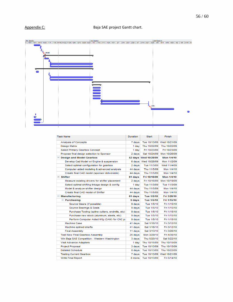
56 / 60 Appendix C:
Baja SAE project Gantt chart.

57 / 60 Appendix D:
Steel hardness conversion chart.

58 / 60
Critical Locations:
Appendix E. Stress Analysis.

59 / 60

60 / 60

Appendix F

2
1
3
4
2
ITEM NO. PART NUMBER DESCRIPTION QTY.
1 drive shaft McMaster 8935K471 *manufacture 1
2 1in bearing McMaster 60355K708 2
3 1.25in snap ring McMaster 97633A320 1
4 gear 54T m2.5 qtc KSS2.5-54 1
ME429 - Winter 2010
CKD BY: INIT: INIT: DRAWN BY: ANDREW SOMEMR
NEXT ASSY:
DATE:
GROUP: BAJA SNEIOR PROJECT
UNITS: INCH
TOLERANCE: SCALE: 1 : 4
DRAWING #: DSA1
TITLE: DRIVESHAFT ASSEMBLY
MATERIAL:

1.95 1.956.57
.10 1.05
1.05
.63
.25
1.25
1.00
ME429 - Winter 2010
CKD BY: INIT: INIT: DRAWN BY: ANDREW SOMMER
NEXT ASSY:
DATE:
GROUP: BAJA SENIOR PROJECT
UNITS: INCH
TOLERANCE: SCALE: 1 : 2
DRAWING #: DS1
TITLE: DRIVE SHAFT
MATERIAL: 4140/4142 STEEL

1.18COUPLING INSERT
QTC KSS2.5-18:MODULE 2.518 TEETH
ME429 - Winter 2010
CKD BY: INIT: INIT: DRAWN BY: ANDREW SOMMER
NEXT ASSY:
DATE:
GROUP: BAJA SENIOR PROJECT
UNITS: INCH
TOLERANCE: SCALE: 2 : 1
DRAWING #: P1
TITLE: QTC KSS2.5-18
MATERIAL: 1045 STEEL COLD DRAWN

1.25std. spline
QTC KSS2.5-54:MODULE 2.554 TEETH
ME429 - Winter 2010
CKD BY: INIT: INIT: DRAWN BY: ANDREW SOMMER
NEXT ASSY:
DATE:
GROUP: BAJA SENIOR PROJECT
UNITS: INCH
TOLERANCE: SCALE: 1 : 2
DRAWING #: G1
TITLE: QTC KSS2.5-54
MATERIAL: AISI 1045 STEEL COLD DRAWN

NUMBERPART
Information in this drawing is provided for reference only.
http://www.mcmaster.com
2"
1"
+0 -0.0005
+0 -0.0004
1/2" +0 -0.0050
60355K708Steel
Double-Sealed Ball Bearing© 2009 McMaster-Carr Supply Company

Unless otherwise specified, dimensions are in inches. Information in this drawing is provided for reference only.
http://www.mcmaster.com© 2006 McMaster-Carr Supply Company
NUMBERPART
1.041-0.015+0.010
0.128Max. Section
Width
0.078
0.182
0.071Min. Section
Width
0.050±0.002Ring
Thickness
1.059±0.004
1.490ClearanceDiameter
Released in Groove
1.125
1.550ClearanceDiameter
Expanded over Shaft
0.056-0.000+0.004
Groove Width
1.059±0.004Groove
Diameter
1.125Shaft
Diameter
0.033Groove Depth
Shaft
97633A320External Retaining RingBlack Phosphate SteelNote: Clearance diameter is the diameter of
a housing that can pass freely over the ring.

Appendix G

BajaSAE 54 Tooth Gear Pocketing
Gear: 54T M2.5 gear from www.qtcgears.com
Tool 002 ENDMILL 00.500 1/2 4 FLUTE CRB EM Program 437 – Origin center of bore, top face of gear
Program 438 – Center of bore, top face, reverse side from prog 437
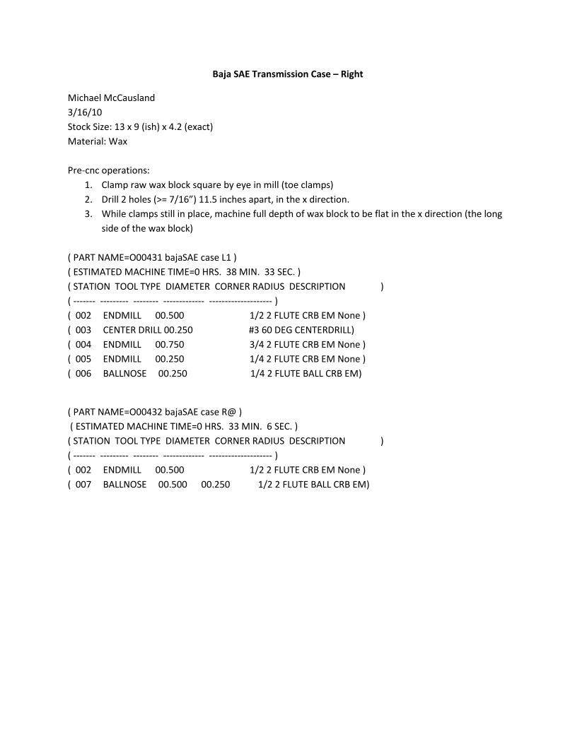
Baja SAE Transmission Case – Right
Michael McCausland 3/16/10 Stock Size: 13 x 9 (ish) x 4.2 (exact) Material: Wax Pre-cnc operations:
1. Clamp raw wax block square by eye in mill (toe clamps) 2. Drill 2 holes (>= 7/16”) 11.5 inches apart, in the x direction. 3. While clamps still in place, machine full depth of wax block to be flat in the x direction (the long
side of the wax block) ( PART NAME=O00431 bajaSAE case L1 ) ( ESTIMATED MACHINE TIME=0 HRS. 38 MIN. 33 SEC. ) ( STATION TOOL TYPE DIAMETER CORNER RADIUS DESCRIPTION ) ( ------- --------- -------- ------------- -------------------- ) ( 002 ENDMILL 00.500 1/2 2 FLUTE CRB EM None ) ( 003 CENTER DRILL 00.250 #3 60 DEG CENTERDRILL) ( 004 ENDMILL 00.750 3/4 2 FLUTE CRB EM None ) ( 005 ENDMILL 00.250 1/4 2 FLUTE CRB EM None ) ( 006 BALLNOSE 00.250 1/4 2 FLUTE BALL CRB EM)
( PART NAME=O00432 bajaSAE case R@ ) ( ESTIMATED MACHINE TIME=0 HRS. 33 MIN. 6 SEC. ) ( STATION TOOL TYPE DIAMETER CORNER RADIUS DESCRIPTION ) ( ------- --------- -------- ------------- -------------------- ) ( 002 ENDMILL 00.500 1/2 2 FLUTE CRB EM None ) ( 007 BALLNOSE 00.500 00.250 1/2 2 FLUTE BALL CRB EM)

O00431 – Side 1, pocket
Origin: Top of stock, center of top left hole
O00432 – Side 2, back
Origin, top of stock, center of top right hole

Manual Transmission Left-side Case Fully Machined Setup 2, Back side
Setup Sheets Michael McCausland 5/11/10 ( PART NAME=O00533 bajaSAE case R2 Alum ) ( ESTIMATED MACHINE TIME=1 HRS. 55 MIN. 25 SEC. ) ( STATION TOOL TYPE DIAMETER CORNER RADIUS DESCRIPTION ) ( ------- --------- -------- ------------- -------------------- ) ( 002 ENDMILL 00.500 1/2 2 FLUTE CRB EM None ) ( 007 BALLNOSE 00.500 00.250 1/2 2 FLUTE BALL CRB EM) ( 003 CENTER DRILL 00.250 #3 60 DEG CENTERDRILL) ( 008 DRILL 00.203 13/64 JOBBER DRILL)

Manual Transmission Left-side Case Fully Machined Setup 2, BackSide Surfaces
Setup Sheets Michael McCausland 5/2/10 ( PROGRAM =O00525 Case left Alum ) ( STATION TOOL TYPE DIAMETER CORNER RADIUS DESCRIPTION ) ( ------- --------- -------- ------------- -------------------- ) ( 007 ENDMILL 00.500 1/2 2 FLUTE CRB EM None ) ( 015 BALLNOSE 00.500 00.250 1/2 2 FLUTE BALL CRB EM) ( 003 CENTER DRILL 00.250 #3 60 DEG CENTERDRILL) ( 010 ENDMILL 00.125 1/8 2 FLUTE CRB EM None ) ( 011 DRILL 00.203 13/64 JOBBER DRILL) ( 012 DRILL 00.335 8.5MM JOBBER DRILL) ( 008 ENDMILL 00.744 3/4 2 FLUTE CRB EM None )

Manual Transmission Left-side Case post-machining Setup Sheets
Michael McCausland 4/24/10 ( PART NAME=O00466 bajaCaseLBearings ) ( PROGRAM NUMBER=0001 ) ( MACHINE=HAAS ) ( STATION TOOL TYPE DIAMETER CORNER RADIUS DESCRIPTION ) ( ------- --------- -------- ------------- -------------------- ) ( 006 ENDMILL 00.500 1/2 2 FLUTE CRB EM None ) ( 002 CENTER DRILL 00.250 #3 60 DEG CENTERDRILL) ( 004 DRILL 00.375 3/8 JOBBER DRILL) ( 008 ENDMILL 00.125 1/8 2 FLUTE CRB EM None ) ( 009 DRILL 00.203 13/64 JOBBER DRILL) ( 010 DRILL 00.335 8.5MM JOBBER DRILL) ( PART NAME=O00467 bajaCaseLbearings2 ) ( PROGRAM NUMBER=0001 ) ( MACHINE=HAAS ) ( STATION TOOL TYPE DIAMETER CORNER RADIUS DESCRIPTION ) ( ------- --------- -------- ------------- -------------------- ) ( 002 CENTER DRILL 00.250 #3 60 DEG CENTERDRILL) ( 003 DRILL 00.250 E, 1/4 JOBBER DRILL) ( 006 ENDMILL 00.500 1/2 2 FLUTE CRB EM None ) ( 005 ENDMILL 00.750 3/4 2 FLUTE CRB EM None ) ( 007 DRILL 00.469 15/32 JOBBER DRILL)

O00466
O00467

Manual Transmission Left-side Case Fully Machined Setup 2, Back side
Setup Sheets Michael McCausland 5/11/10 ( PART NAME=O00533 bajaSAE case R2 Alum ) ( ESTIMATED MACHINE TIME=1 HRS. 56 MIN. 28 SEC. ) ( STATION TOOL TYPE DIAMETER CORNER RADIUS DESCRIPTION ) ( ------- --------- -------- ------------- -------------------- ) ( 007 ENDMILL 00.500 1/2 2 FLUTE CRB EM None ) ( 002 ENDMILL 00.500 1/2 2 FLUTE CRB EM None ) ( 008 BALLNOSE 00.500 00.250 1/2 2 FLUTE BALL CRB EM) ( 003 CENTER DRILL 00.250 #3 60 DEG CENTERDRILL) ( 009 DRILL 00.203 13/64 JOBBER DRILL)

Fully Machined 6061 Transmission Case Right Half – O00532
( PART NAME=O00532 bajaSAE case R1 Alum ) ( ESTIMATED MACHINE TIME=4 HRS. 16 MIN. 2 SEC. ) ( STATION TOOL TYPE DIAMETER CORNER RADIUS DESCRIPTION ) ( ------- --------- -------- ------------- -------------------- ) ( 002 FACEMILL 03.000 3.0 Aluminator Mill) ( 003 CENTER DRILL 00.250 #3 60 DEG CENTERDRILL) ( 004 DRILL 00.246 D JOBBER DRILL) ( 005 REAM 00.248 0.251 REAMER) ( 006 DRILL 00.375 3/8 JOBBER DRILL) ( 007 ENDMILL 00.500 1/2 2 FLUTE CRB EM None ) ( 008 BALLNOSE 00.500 00.250 1/2 2 FLUTE BALL CRB EM) ( 009 ENDMILL 00.744 3/4 2 FLUTE CRB EM None ) ( 010 DRILL 00.469 15/32 JOBBER DRILL) ( 011 ENDMILL 00.250 1/4 2 FLUTE CRB EM None ) Stock: 12” x 12” x 4.086” Origin: Top dead center

Baja SAE transmission Case – Left Half
Michael McCausland
Material: Wax (to be cast to aluminum) Stock size: roughly 13” x 9” x 4.36” Prior to Machine setup: drill 0.5” through holes in stock ~ 0.5” from top and 0.75” from left edge. 11.5” apart
( PART NAME=O00411 bajaSaeCaseLeft1 ) ( ESTIMATED MACHINE TIME=0 HRS. 38 MIN. 6 SEC. ) ( STATION TOOL TYPE DIAMETER CORNER RADIUS DESCRIPTION ) ( ------- --------- -------- ------------- -------------------- ) ( 002 ENDMILL 0.500 1/2 2 FLUTE CRB EM None ) ( 003 CENTER DRILL 0.250 #3 60 DEG CENTERDRILL) ( 004 ENDMILL 0.750 3/4 2 FLUTE CRB EM None )
( PART NAME=O00412 bajSaeCaseLeft2 ) ( ESTIMATED MACHINE TIME=0 HRS. 35 MIN. 39 SEC. ) ( STATION TOOL TYPE DIAMETER CORNER RADIUS DESCRIPTION ) ( ------- --------- -------- ------------- -------------------- ) ( 002 ENDMILL 00.500 1/2 2 FLUTE CRB EM None ) ( 003 CENTER DRILL 00.250 #3 60 DEG CENTERDRILL) ( 004 ENDMILL 00.750 3/4 2 FLUTE CRB EM None ) ( 005 ENDMILL 00.125 1/8 2 FLUTE CRB EM None ) ( 006 BALLNOSE 00.500 1/2 2 FLUTE BALL CRB EM)

Notes: Programs will give a M00 (pause) after the 2nd toolpath this means MOVE THE TOE CLAMPS, stupid.
O00411
O00412

Shift Mechanism Cover
Mike McCausland Material: UHMW PE Stock Size: 6” x 6” x 0.75”
Setup1: O00409 – Shift cover1
Tooling List:
( PART NAME=O00409 shift cover1 ) ( ESTIMATED MACHINE TIME=0 HRS. 8 MIN. 37 SEC. ) ( STATION TOOL TYPE DIAMETER CORNER RADIUS DESCRIPTION ) ( ------- --------- -------- ------------- -------------------- ) ( 002 ENDMILL 00.375 3/8 3 FLUTE CRB EM None ) ( 003 CENTER DRILL 00.250 #3 60 DEG CENTERDRILL) ( 004 DRILL 00.189 #12 JOBBER DRILL) ( PART NAME=O00410 Shift cover2 ) ( ESTIMATED MACHINE TIME=0 HRS. 3 MIN. 40 SEC. ) ( STATION TOOL TYPE DIAMETER CORNER RADIUS DESCRIPTION ) ( ------- --------- -------- ------------- -------------------- ) ( 002 ENDMILL 00.375 3/8 3 FLUTE CRB EM None )

( PART NAME=Baja SAE Shift Lever ) ( PROGRAM NUMBER=413 ) ( ESTIMATED MACHINE TIME=0 HRS. 12 MIN. 60 SEC. ) ( STATION TOOL TYPE DIAMETER CORNER RADIUS DESCRIPTION ) ( ------- --------- -------- ------------- -------------------- ) ( 001 ENDMILL 0.500 1/2 2 FLUTE CRB EM None ) ( 002 CENTER DRILL 0.250 #3 60 DEG CENTERDRILL) ( 003 DRILL 0.375 3/8 JOBBER DRILL) ( 004 DRILL 0.149 25 JOBBER DRILL)

Sprocket Adapter
Material: 4140 steel
Stock size: 6” round x 1” thick
O00446 – Origin top dead center of stock (leaves extra material to allow for weld warpage)
O00447 – Origin top dead center, reverse side. (leaves extra material to allow for weld warpage)
( 002 FACEMILL 03.000 3.0 Steel Face Mill) ( 003 ENDMILL 00.500 1/2 4 FLUTE CRB EM None )

[ end of report ]