sae mini baja: suspension and steeringsae mini baja: suspension and steering by zane cross, kyle...
TRANSCRIPT
1
SAE Mini BAJA: Suspension and
Steering
By
Zane Cross, Kyle Egan, Nick Garry, Trevor Hochhaus
Team 11
Project Progress
Submitted towards partial fulfillment of the requirements for
Mechanical Engineering Design II – Spring 2015
Department of Mechanical Engineering
Northern Arizona University
Flagstaff, AZ 86011
2
Table of Contents Introduction ................................................................................................................................................... 3
Front Suspension ........................................................................................................................................... 3
Rear Suspension .......................................................................................................................................... 11
Steering Changes and Progress ................................................................................................................... 15
Wheelbase and Track Width ................................................................................................................... 15
Ackerman Angles and Turning Radius ................................................................................................... 16
Final Steering Dimensions ...................................................................................................................... 17
Manufacturing of Steering System ......................................................................................................... 19
Conclusion .................................................................................................................................................. 20
References ................................................................................................................................................... 21
Appendix ..................................................................................................................................................... 22
3
Introduction The engineering process is one of many iterations. During the design process one cannot
foresee future complications such as manufacturing constraints and design changes within other
components. Because of these unforeseeable complications the design of the suspension and
steering systems have been altered from the original design decided upon last semester. The
changes will increase weight in some areas but the team believes that these changes will achieve
the same results as our original design in competition.
Front Suspension The old design for the Baja’s front A-arm style suspension had to be redesigned for a few
reasons. One major reason was that the final product of the frame was not to the same
specifications as the frame our suspension was designed to. This created issues with tab design
and placement. The design also only allowed for minimal amounts of travel from the shock both
in compression and extension. The shock placement on the lower A-arm also raised concerns on
potential interference between the tie rods and the mounting tabs for the shock. The last problem
the old design faced was that the suspension could only be slightly adjusted for positive caster,
and that it would be neutral. This is an issue because the car will need positive caster from
assembly to be reliably stable and avoid any possibility of negative caster.
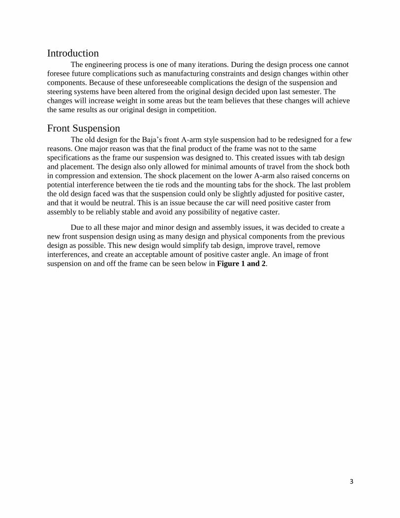
Due to all these major and minor design and assembly issues, it was decided to create a
new front suspension design using as many design and physical components from the previous
design as possible. This new design would simplify tab design, improve travel, remove
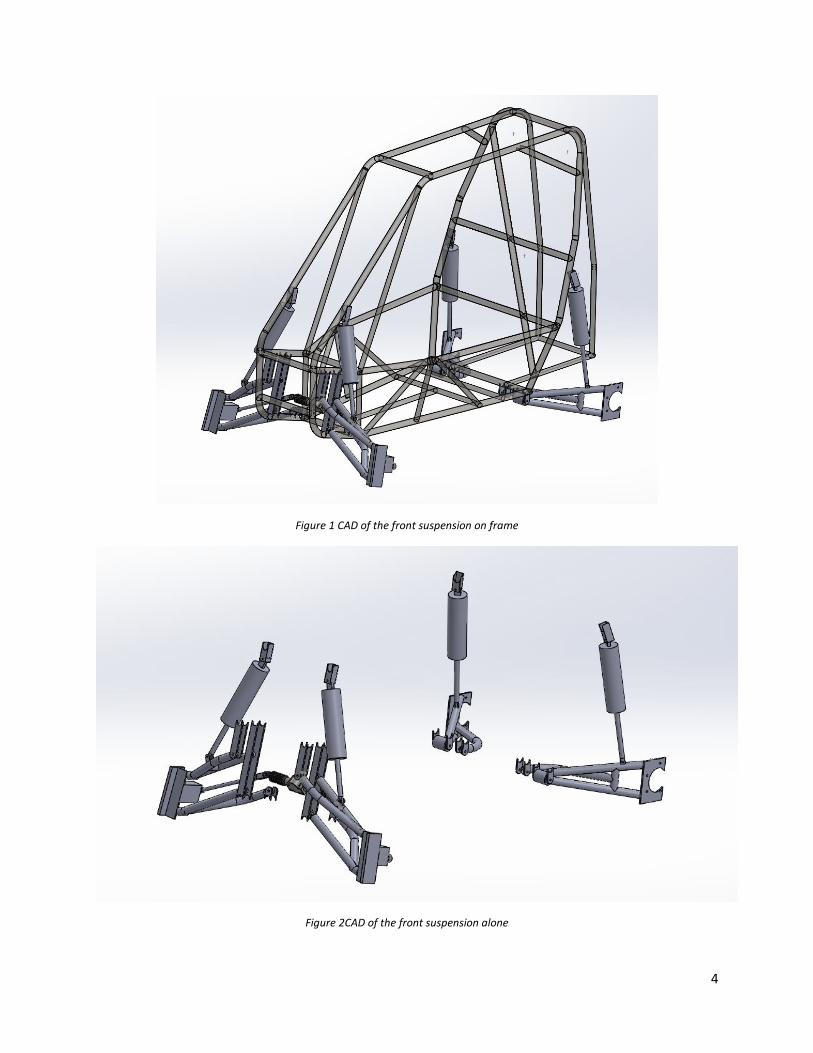
interferences, and create an acceptable amount of positive caster angle. An image of front
suspension on and off the frame can be seen below in Figure 1 and 2.
4
Figure 1 CAD of the front suspension on frame
Figure 2CAD of the front suspension alone
5
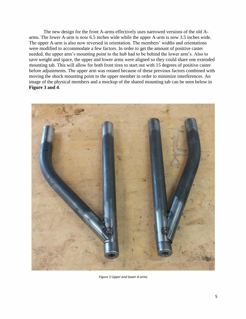
The new design for the front A-arms effectively uses narrowed versions of the old A-
arms. The lower A-arm is now 6.5 inches wide while the upper A-arm is now 3.5 inches wide.
The upper A-arm is also now reversed in orientation. The members’ widths and orientations
were modified to accommodate a few factors. In order to get the amount of positive caster
needed, the upper arm’s mounting point to the hub had to be behind the lower arm’s. Also to
save weight and space, the upper and lower arms were aligned so they could share one extended
mounting tab. This will allow for both front tires to start out with 15 degrees of positive caster
before adjustments. The upper arm was rotated because of these previous factors combined with
moving the shock mounting point to the upper member in order to minimize interferences. An
image of the physical members and a mockup of the shared mounting tab can be seen below in
Figure 3 and 4.
Figure 3 Upper and lower A-arms

6
Figure 4 Mockup of lower A-arm and mounting tab
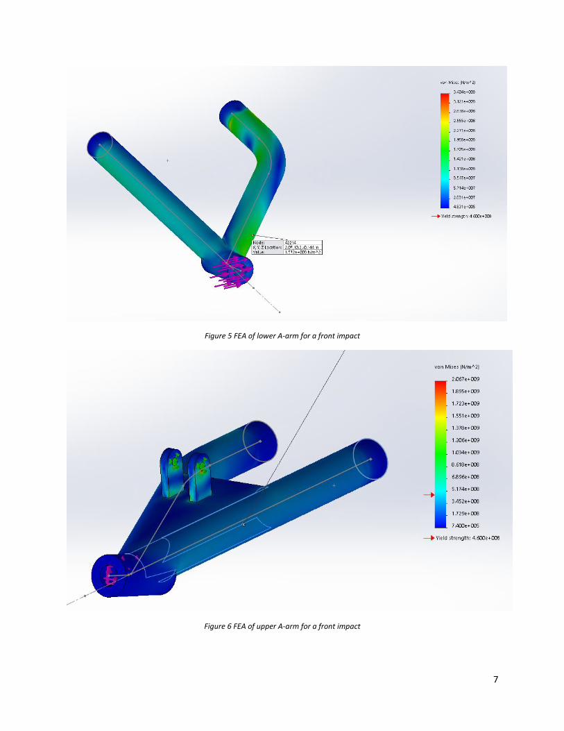
In order to ensure that this new design will be durable during competition, finite element
analysis was performed on the upper and lower A-arms for three different impact scenarios. The
first scenario simulates a front impact at 10 mph where only one wheel makes contact with an
obstacle and brings the entire car to a stop. This represents a real life scenario where the car hits
a large rock, tree, dropped engine, or stopped vehicle on the track. The result for both the lower
and upper A-arm can be seen below in Figures 5 and 6.
7
Figure 5 FEA of lower A-arm for a front impact
Figure 6 FEA of upper A-arm for a front impact
8
The factor of safety for the upper member was 2.9 and 1.8 for the lower. This loading is
considered unlikely for a few reasons. The upward rake of the suspension will allow for a portion
of the force to be absorbed by the shock. This simulation also assumes that the car comes to a
stop almost instantaneously. The car will most likely have a larger amount of time before its
momentum is reduced to zero. This means that real life impacts will have much more reduced
loads exerted on the arms. Therefore, the arm designs can be considered durable for the
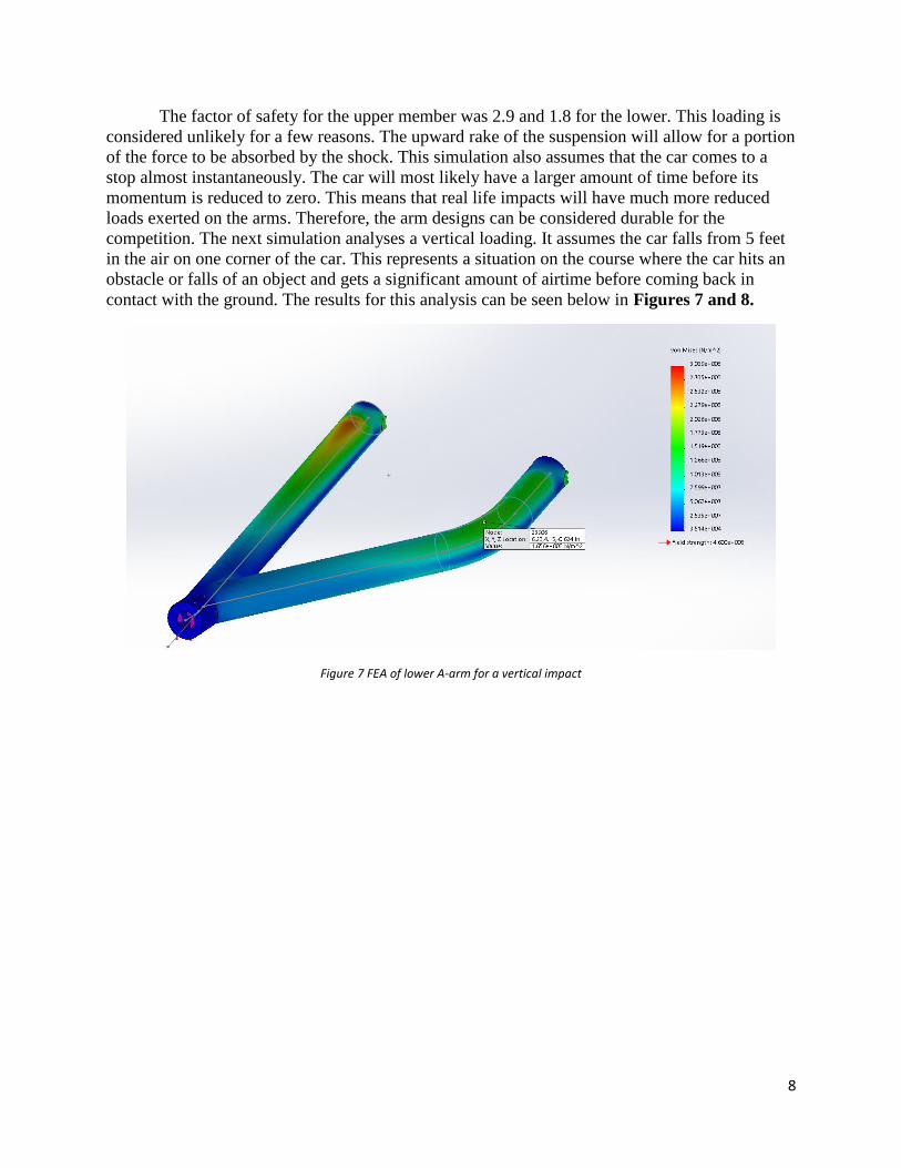
competition. The next simulation analyses a vertical loading. It assumes the car falls from 5 feet
in the air on one corner of the car. This represents a situation on the course where the car hits an
obstacle or falls of an object and gets a significant amount of airtime before coming back in
contact with the ground. The results for this analysis can be seen below in Figures 7 and 8.
Figure 7 FEA of lower A-arm for a vertical impact

9
Figure 8 FEA of upper A-arm for a vertical impact
The factor of safety for the lower arm was 2.8 and 8 for the upper arm. This scenario is
unlikely to see in a real life situation because another portion of the car will always come into
contact with the ground before one corner of the suspension bottoms out, whether it is the frame
or another wheel. That will distribute the load among the car reducing the impact on any corner.
The final impact scenario analyses another vehicle impacting one corner of the suspension. The
other vehicle will be moving at 5 mph with reference to the car. This replicates a situation on the
track where the car is side by side with another vehicle and makes contact with only one wheel.
The results for this analysis are shown below in Figures 9 and 10.

10
Figure 9 FEA of lower A-arm for a side impact
Figure 10 FEA of upper A-arm for a side impact
The factor of safety for the lower arm was 2 and 2.9 for the lower. The only reason that
this analysis may be unrealistic is that it would be difficult, but not impossible, to come in
contact with another vehicle without any contact on other parts of the vehicle.

11
Overall, the results from the finite element analysis show that the suspension can survive
rarer and more extreme impacts. This directly translates to the suspensions survivability for more
average and expected loadings.
Rear Suspension The largest change from last semester is the switch to a one link system in the rear. This
change occurred for multiple reason. The first cause for change was the fact that the final
dimensions of the drivetrain which is housed in the rear of the vehicle is still unknown. Without
exact dimensions of the rear structure the team could not properly design a double A-arm
suspension. If the team were to wait until the dimensions were finalized we would not have time
to test the vehicle, hindering our ability to compete. The one link system is the ideal replacement
because it is not constrained by the rear of the vehicle. It mounts at a single axis line which
resides on the firewall. It was decided to place another bar coming from the one link to help with
axial force. This will be stronger and will not require another linkage. As seen below in Figure
11, you can see a top view of the rear suspension.
Figure 11 Top view of rear suspension
The shock placement has been decided as the shock will max out at 22 in. It will be
placed towards the end of the link and will connect to the frame on the roll cage. You can see the
shock placement in Figure 12.
12
Figure 12 Side view of the rear suspension
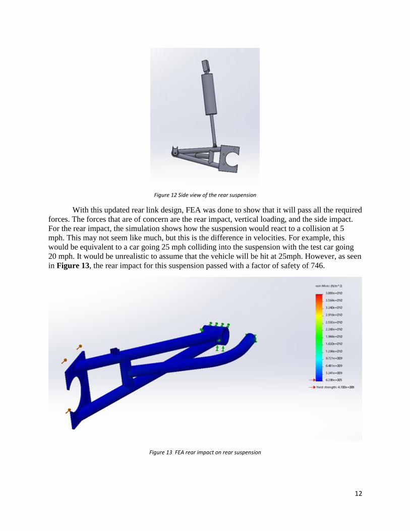
With this updated rear link design, FEA was done to show that it will pass all the required
forces. The forces that are of concern are the rear impact, vertical loading, and the side impact.
For the rear impact, the simulation shows how the suspension would react to a collision at 5
mph. This may not seem like much, but this is the difference in velocities. For example, this
would be equivalent to a car going 25 mph colliding into the suspension with the test car going
20 mph. It would be unrealistic to assume that the vehicle will be hit at 25mph. However, as seen
in Figure 13, the rear impact for this suspension passed with a factor of safety of 746.
Figure 13 FEA rear impact on rear suspension
13
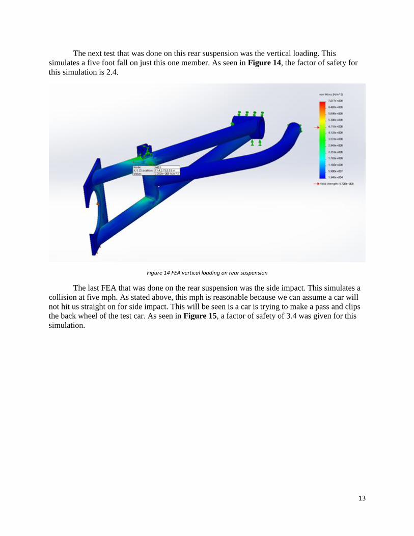
The next test that was done on this rear suspension was the vertical loading. This
simulates a five foot fall on just this one member. As seen in Figure 14, the factor of safety for
this simulation is 2.4.
Figure 14 FEA vertical loading on rear suspension
The last FEA that was done on the rear suspension was the side impact. This simulates a
collision at five mph. As stated above, this mph is reasonable because we can assume a car will
not hit us straight on for side impact. This will be seen is a car is trying to make a pass and clips
the back wheel of the test car. As seen in Figure 15, a factor of safety of 3.4 was given for this
simulation.

14
Figure 15 FEA side impact on rear suspension
As of now, the pipe members of the rear suspension have been fabricated and is ready to
be welded to the bushing that attaches on the frame. A picture of the rear suspension being built
can be seen in Figure 16.

15
Figure 16 Fabricating the rear suspension
Steering Changes and Progress
Wheelbase and Track Width With the various changes to the dimensions of the front and rear suspension of the vehicle,
steering calculations previously evaluated needed to be re-evaluated with the final front and rear
suspension design. One of the first calculations that needed to be re-evaluated from our previous design
was the final track width and wheelbase of the vehicle. These calculations needed to be finalized, because
they play a large role in the turning radius and Ackerman angles required to achieve the desired turning
radius of the vehicle. The finalized track width and wheelbase of the vehicle are pictured in the schematic
in Figure 17.
16
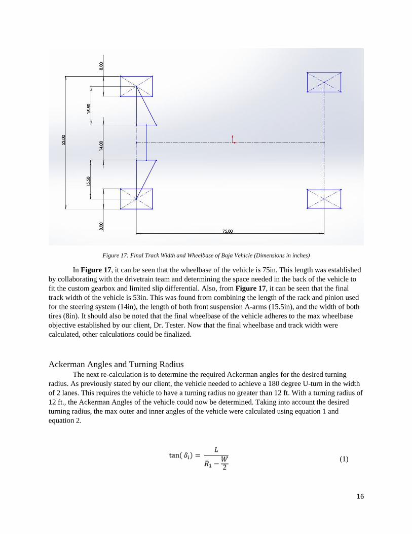
Figure 17: Final Track Width and Wheelbase of Baja Vehicle (Dimensions in inches)
In Figure 17, it can be seen that the wheelbase of the vehicle is 75in. This length was established
by collaborating with the drivetrain team and determining the space needed in the back of the vehicle to
fit the custom gearbox and limited slip differential. Also, from Figure 17, it can be seen that the final
track width of the vehicle is 53in. This was found from combining the length of the rack and pinion used
for the steering system (14in), the length of both front suspension A-arms (15.5in), and the width of both
tires (8in). It should also be noted that the final wheelbase of the vehicle adheres to the max wheelbase
objective established by our client, Dr. Tester. Now that the final wheelbase and track width were
calculated, other calculations could be finalized.
Ackerman Angles and Turning Radius The next re-calculation is to determine the required Ackerman angles for the desired turning
radius. As previously stated by our client, the vehicle needed to achieve a 180 degree U-turn in the width
of 2 lanes. This requires the vehicle to have a turning radius no greater than 12 ft. With a turning radius of
12 ft., the Ackerman Angles of the vehicle could now be determined. Taking into account the desired
turning radius, the max outer and inner angles of the vehicle were calculated using equation 1 and
equation 2.
(1)
17
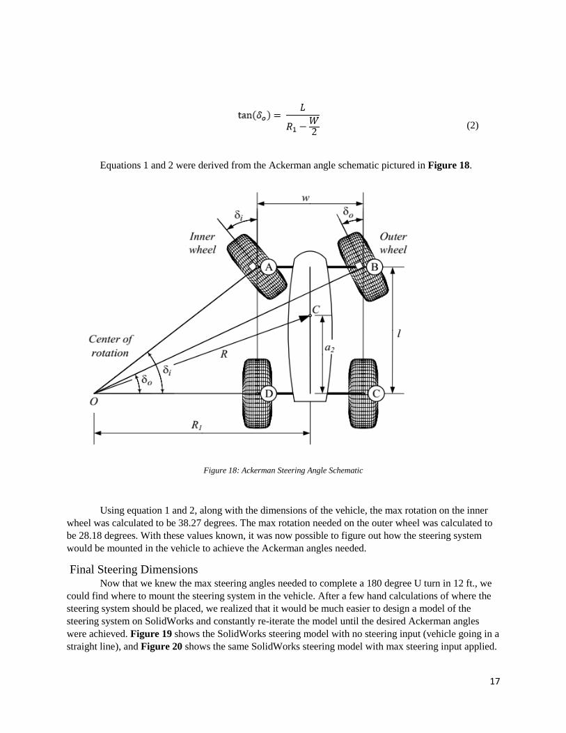
(2)
Equations 1 and 2 were derived from the Ackerman angle schematic pictured in Figure 18.
Figure 18: Ackerman Steering Angle Schematic
Using equation 1 and 2, along with the dimensions of the vehicle, the max rotation on the inner
wheel was calculated to be 38.27 degrees. The max rotation needed on the outer wheel was calculated to
be 28.18 degrees. With these values known, it was now possible to figure out how the steering system
would be mounted in the vehicle to achieve the Ackerman angles needed.
Final Steering Dimensions Now that we knew the max steering angles needed to complete a 180 degree U turn in 12 ft., we
could find where to mount the steering system in the vehicle. After a few hand calculations of where the
steering system should be placed, we realized that it would be much easier to design a model of the
steering system on SolidWorks and constantly re-iterate the model until the desired Ackerman angles
were achieved. Figure 19 shows the SolidWorks steering model with no steering input (vehicle going in a
straight line), and Figure 20 shows the same SolidWorks steering model with max steering input applied.
18
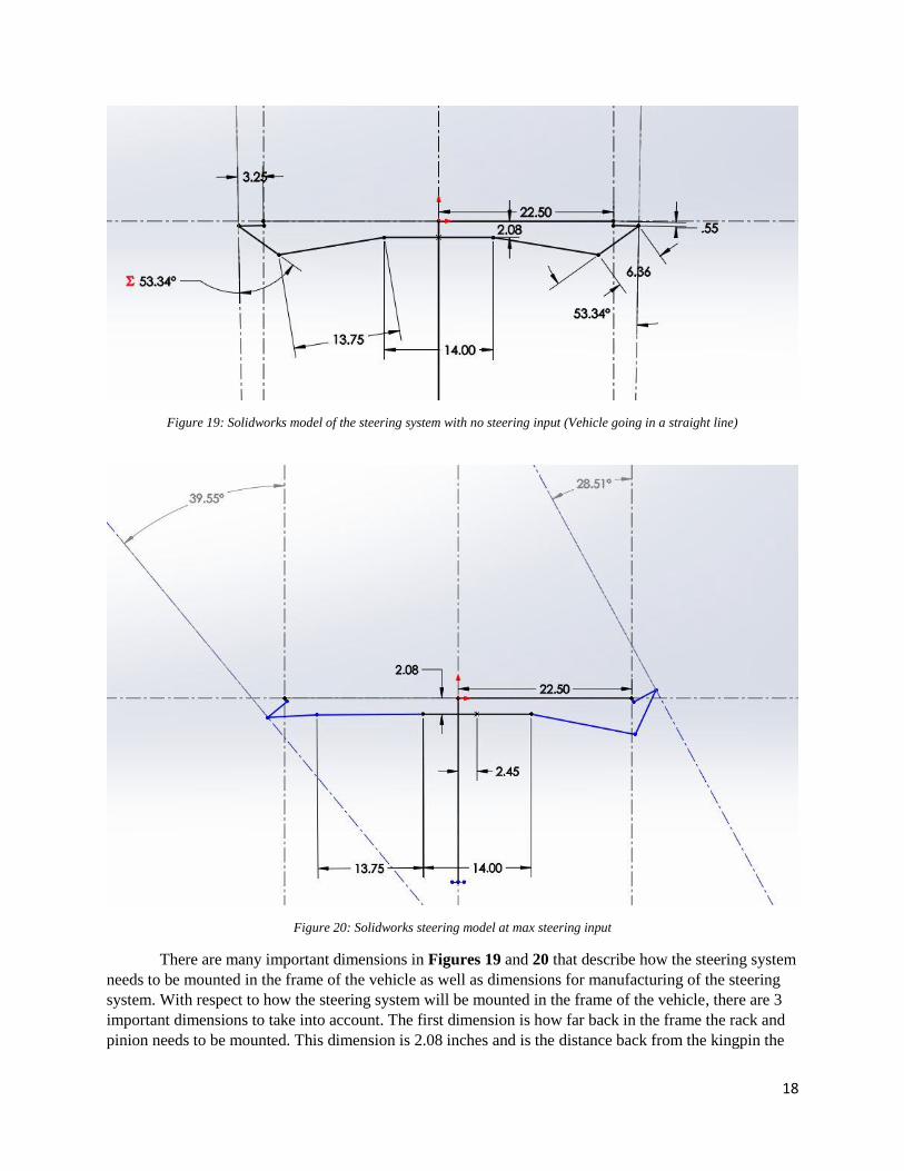
Figure 19: Solidworks model of the steering system with no steering input (Vehicle going in a straight line)
Figure 20: Solidworks steering model at max steering input
There are many important dimensions in Figures 19 and 20 that describe how the steering system
needs to be mounted in the frame of the vehicle as well as dimensions for manufacturing of the steering
system. With respect to how the steering system will be mounted in the frame of the vehicle, there are 3
important dimensions to take into account. The first dimension is how far back in the frame the rack and
pinion needs to be mounted. This dimension is 2.08 inches and is the distance back from the kingpin the

19
steering rack needs to be mounted in the vehicle. The second important dimension is how far back on the
hub the new tie rod mount needs to be placed. This distance is not shown on the SolidWorks schematic,
but using the measuring tool in SolidWorks, the distance was calculated to be 4.32 in. The final important
dimension is the distance that the new hub mount needs to be located from the kingpin. Although this
distance is also not shown in the steering model, using the SolidWorks measuring tool, the distance
calculated is 1.93 in.
There are also many important dimensions that can be taken from Figures 19 and 20 with respect
to the manufacturing of the steering system. One important dimension is the length of the tie rod. Based
on Figures 20, this was calculated to be 13.75 in. Another important dimension is the distance the rack
and pinion moves linearly. This dimension is also shown in Figure 4 and was calculated to be 2.45 in.
From Figures 20, it can be seen that the inner wheel rotation is 39.55 degrees and the outer wheel
rotation is 28.51 degrees. Knowing this, we can conclude that the steering system will achieve the desired
Ackerman steering angles with the dimensions described above.
Manufacturing of Steering System Now that all the dimensions of the vehicle steering system where finalized, the last step is to
manufacture all necessary parts to mount the steering system to the vehicle. One steering component that
has already been manufactured is the tie rods. Figures 21 shows the manufactured tie rods.
Figure 21: Manufactured Tie Rods with Clevis Joints

20
The tie rods were threaded on both ends to accommodate the clevis joint and female heim-joint.
As pictured in Figures 21, the clevis joints are already mounted to the tie rods. The female heim-joints
that are installed on the opposite end of the tie rod are currently being ordered. Figures 22 shows how the
tie rods will be mounted to the rack and pinion.
Figure 22: Rack and Pinion attached to manufactured Tie Rods
Conclusion Although the team came upon many obstacles while trying to implement the first design,
we used our previous knowledge to overcome and design unique suspension and steering
systems that will meet all of our customer requirements. The new designs pass all possible
loadings that the vehicle might see during competition. The necessary alterations to the design
have put the team behind schedule. The team looks to make up this time over the break when the
rest of the materials needed to complete the suspension systems will be readily available. The
new deadline for a rolling chassis is March 26th. We are confident that we will meet this
deadline.

21
References
R. Hibbeler, Mechanics of Materials, Upper Saddle River : Pearson Prentice Hall, 2011.
http://www.idsc.ethz.ch/Courses/vehicle_dynamics_and_design/11_0_0_Steering_Thero
y.pdf
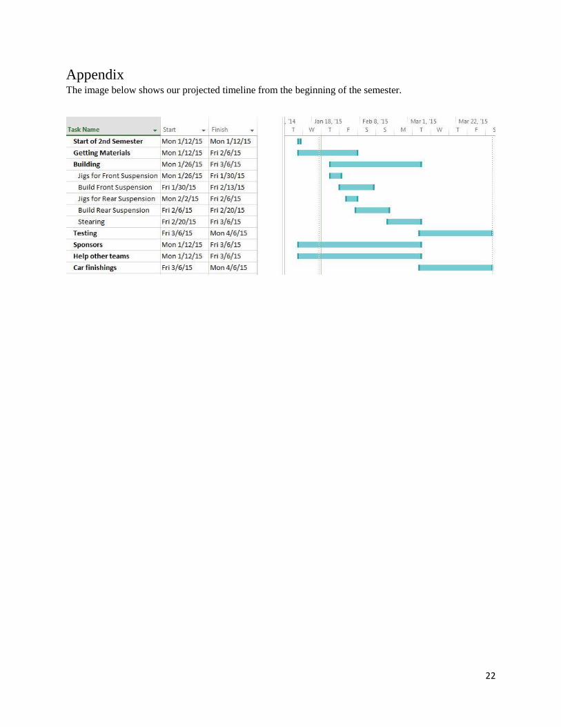
22
Appendix The image below shows our projected timeline from the beginning of the semester.