safe and reliable photovoltaic energy generation en
DESCRIPTION
photovoltaic power plantsTRANSCRIPT

Safe and reliable photovoltaic energy generation
1
Safe and reliable photovoltaic energy generationSelection of low voltage switchgears and circuit protection components per type of photovoltaic electrical architecture

2
Safe and reliable photovoltaic energy generation
22
ContentsIntroductionScope and purpose of this paper
1 PV system and installation rules 1.1 How to ensure safety during normal operation?
1.1.1 Protecting people against electric shock1.1.2 Risk of fire: protection against thermal effects1.1.3. Protection of PV modules against reverse current1.1.4. Protection against overcurrent1.1.5. Circuit breakers or fuses1.1.6. Switchgear and enclosure selection
1.2 Protection against overvoltage: surge protection1.2.1 Protection by equipotential bonding1.2.2. Protection by surge protection devices (SPDs)
1.3 How to ensure safety during maintenance or emergency 1.3.1 Isolation switching and control 1.3.2 Selecting and installing enclosures
1.4 How to ensure safety during all the life cycle of the installation
2 Products & enclosure selection according to architectures 2.1 Grid-connected PV system ≤ 10 kW (residential)
2.1.1 One single phase inverter 2.2 10 kW-100 kW grid-connected PV system (small buildings)
2.2.1 Three-phase multi-input inverter without array box 2.2.2 Three-phase inverter with one array box2.2.3 Multi single-phase inverters design2.2.4 Three-phase inverter with two array boxes (Na ≤ 2)
2.3 150 kW to 500 kW grid-connected PV system (large buildings and farms) 2.3.1 Three-phases inverter with more than two array boxes2.3.2 Multi three-phase inverter design without array box
2.4 Multi MW grid-connected PV system (large buildings and farms)
3. Additional information for large centralized inverter (100 – 630 kW)
4. Detailed characteristics of DC-PV switchgears 4.1 DC-PV switch disconnectors
4.2 DC-PV switch disconnectors - accessories
4.3 DC-PV switch disconnectors - temperatures de-rating
4.4 DC-PV overcurrent protection
4.5 DC-PV overcurrent protection - accessories
4.6 DC-PV overcurrent protection - temperature de-rating
Conclusion
Definition (Ref IEC 60364-7-712)
Safe and reliable photovoltaic energy generation
3
Introduction
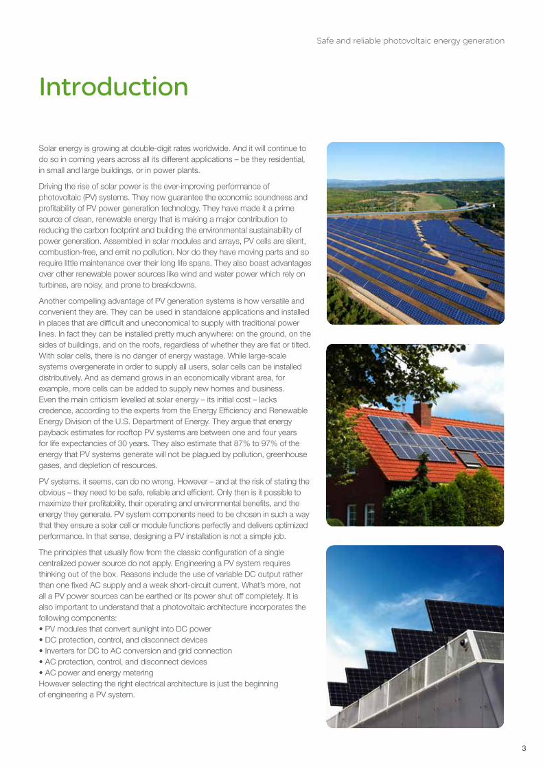
Solar energy is growing at double-digit rates worldwide. And it will continue to do so in coming years across all its different applications – be they residential, in small and large buildings, or in power plants.
Driving the rise of solar power is the ever-improving performance of photovoltaic (PV) systems. They now guarantee the economic soundness and profitability of PV power generation technology. They have made it a prime source of clean, renewable energy that is making a major contribution to reducing the carbon footprint and building the environmental sustainability of power generation. Assembled in solar modules and arrays, PV cells are silent, combustion-free, and emit no pollution. Nor do they have moving parts and so require little maintenance over their long life spans. They also boast advantages over other renewable power sources like wind and water power which rely on turbines, are noisy, and prone to breakdowns.
Another compelling advantage of PV generation systems is how versatile and convenient they are. They can be used in standalone applications and installed in places that are difficult and uneconomical to supply with traditional power lines. In fact they can be installed pretty much anywhere: on the ground, on the sides of buildings, and on the roofs, regardless of whether they are flat or tilted. With solar cells, there is no danger of energy wastage. While large-scale systems overgenerate in order to supply all users, solar cells can be installed distributively. And as demand grows in an economically vibrant area, for example, more cells can be added to supply new homes and business. Even the main criticism levelled at solar energy – its initial cost – lacks credence, according to the experts from the Energy Efficiency and Renewable Energy Division of the U.S. Department of Energy. They argue that energy payback estimates for rooftop PV systems are between one and four years for life expectancies of 30 years. They also estimate that 87% to 97% of the energy that PV systems generate will not be plagued by pollution, greenhouse gases, and depletion of resources.
PV systems, it seems, can do no wrong. However – and at the risk of stating the obvious – they need to be safe, reliable and efficient. Only then is it possible to maximize their profitability, their operating and environmental benefits, and the energy they generate. PV system components need to be chosen in such a way that they ensure a solar cell or module functions perfectly and delivers optimized performance. In that sense, designing a PV installation is not a simple job.
The principles that usually flow from the classic configuration of a single centralized power source do not apply. Engineering a PV system requires thinking out of the box. Reasons include the use of variable DC output rather than one fixed AC supply and a weak short-circuit current. What’s more, not all a PV power sources can be earthed or its power shut off completely. It is also important to understand that a photovoltaic architecture incorporates the following components:• PV modules that convert sunlight into DC power• DC protection, control, and disconnect devices• Inverters for DC to AC conversion and grid connection• AC protection, control, and disconnect devices• AC power and energy meteringHowever selecting the right electrical architecture is just the beginning of engineering a PV system.

2
Safe and reliable photovoltaic energy generation
24
Scope and purpose of this paper
This application paper seeks to offer guidance in selecting the best protection and control components for a given PV system in residential premises, commercial buildings, and power plants.
It also sets out guidelines for optimizing system operation, maximizing the safety of people and property, and ensuring continuity of service.
The type of PV installation chosen to illustrate the selection of the right architecture and the installation of low-voltage switchgear is a grid-connected photovoltaic installation with an open-circuit maximum voltage (UOC MAX) higher than 120 V DC (see figure below). The assumption is that the PV generator architecture and characteristics (voltage, current, PV modules, etc.) have been selected. The PV array’s maximum voltage is considered equal to UOC MAX corrected to the lowest expected ambient temperature in accordance with the manufacturer’s instructions or installation rules.
The figures below shows a typical PV architecture with the terms generally used in this document.
The switchgear for which guidance is provided encompasses:• Switches• Fuse carriers• Circuit breakers• Contactors• Enclosures• Surge protectors.
This paper also proposes answers to questions such as:• Whether or not overcurrent protection is required
and whether the best option is to use fuses or a circuit breaker.
• Where to use switches.• Which enclosures are recommended.
IEC standard 60364 is applied throughout this document. Part 712 of the standard is of particular significance. It sets out rules for ensuring that solar photovoltaic power systems are safe and supplies a number of the definitions used in this paper (see “Definitions” at the end of the document).
Array junction boxArray junction box
Generator junction box
Inverter
DC Side
AC Side
PV module
PV s tring
PV arrayPV installation
Connection to AC installation (grid box)
String current
Array current
Generator current
Na = Number of arrays
Np = Number of strings / array
Ns = Total number of strings

Safe and reliable photovoltaic energy generation
5
PV system and installation rules1

2
Safe and reliable photovoltaic energy generation
26
1.1. How to ensure safety during normal operation?
Two particular characteristics of PV generators are their DC voltage levels and the fact they cannot be shut off as long as PV modules are exposed to the sun. The short-circuit current produced by the PV module is too low to trigger the power supply’s automatic disconnect. The most frequently used protective measures do not therefore apply to PV systems. However, as PV modules are installed outdoors they are exposed to the elements. And since they can be installed on roofs, critical attention should be paid to the risk of fire and the protection of fire fighters and emergency services staff.
1.1.1. Protecting people against electric shock
IEC 60364-712 stipulates that PV systems whose maximum UOC MAX is higher than 120 V DC should use « double or reinforced insulation » as a protection against electric shock.
Switchgear, such as fuses or circuit breakers on the DC side, do not afford protection against electric shock as there is no automatic disconnect of the power supply.
Overcurrent protection, when used, protects PV cells against reverse current and cables against overload.
Earthing a pole on the DC side is functional and does not protect against electric shocks.
1.1.2. Risk of fire: protection against thermal effects
Generally speaking there are three situations that can lead to abnormally high temperatures and the risk of fire in a PV system: insulation fault, a reverse current in a PV module, and overloading cables or equipment.
Insulation fault detectionDouble or reinforced insulation is a protective measure against electric shock but it does not exclude all risk of insulation fault. (The assumption here is that the likelihood of an insulation fault and of someone touching an energised part of the installation at the same is very low. Insulation faults in themselves do happen more frequently, however.) DC insulation fault could be more dangerous as arc has less chance to extinguish by itself as it does in AC.
The PV generator should be checked to ensure it is insulated from earth.
> When there is no galvanic insulation between the AC side and the DC side:• It is impossible to earth one pole.• AC protection can be used to detect insulation faults.
> When the AC side and DC side are galvanically separated:• An overcurrent protective device (which also detects insulation faults) should be used to trip the grounded conductor in the event of a fault, if the PV cell technology (e.g. thin films of amorphous silicon) requires one of the conductors to be directly grounded.• An insulation monitoring device should be used if the PV cell technology requires one of the conductors to be resistance-grounded.• An insulation monitoring device should also be used when PV cell technology does not require either conductor to be earthed.
Insulation monitoring device shall be selected taking into consideration both UOC MAX and the capacitance between poles and earth causes leakage current. In addition cables and inverter capacitance should be also considered. An Insulation monitoring device able to handle capacitance up to 500 µF is suitable for PV system.
Paragraph 412.1.1 of IEC 60364 states:Double or reinforced insulation is a protective measure in which• basic protection is provided
by basic insulation, and fault protection is provided by supplementary insulation, or
• basic and fault protection is provided by reinforced insulation between live parts and accessible parts.
NB: This protective measure is intended to prevent the appearance of dangerous voltage on the accessible parts of electrical equipment through a fault in the basic insulation.
Please note When an insulation fault is detected whatever the solution is, inverter is stopped and disconnected from AC side, but the fault is still present on DC side and voltage between poles is open circuit voltage of PV generator as long as sun is shining. This situation cannot be tolerated over a long period and the fault has to be found and cleared. If not, a second fault may develop on the other pole, causing the current to circulate in the earthing conductors and metal parts of the PV installation with no guarantee that protective devices will operate properly. See “1.1.4 Protection against overcurrent”.

Safe and reliable photovoltaic energy generation
7
Leakage capacitance in various PV systemsThe literature provided by manufacturers of photovoltaic modules yield the following figures:
1.1.3. Protection of PV modules against reverse current
A short circuit in a PV module, faulty wiring, or a related fault may cause reverse current in PV strings. This occurs if the open-circuit voltage of one string is significantly different from the open voltage of parallel strings connected to the same inverter. The current flows from the healthy strings to the faulty one instead of flowing to the inverter and supplying power to the AC network. Reverse current can lead to dangerous temperature rises and fires in the PV module. PV module withstand capability should therefore be tested in accordance with IEC 61730-2 standard and the PV module manufacturer shall provide the maximum reverse current value (IRM).
Some measurements made in European plants are giving the following figures:
Maximum power usually developed with a single inverter
Surface necessary to develop such a Power
Usual capacitance by m2
Usual capacitance between lines and earth for a single IT system
Frameless glass-glass module with aluminium frame on an assembly stand (open air)
1 MW 8000 m² 1 nF/m² 8 µF
In-roof glass-glass module with aluminium frame
100 kW 800 m² 5 nF/m² 4 µF
Thin-film PV module on flexible substrate
100 kW 800 m² 50 nF/m² 40 µF
Maximum power developed with a single inverter
Surface necessary to develop such a Power
Lowest capacitance measurement
Highest capacitance measurement
Maximum measured capacitance by m2
Frameless glass-glass module with aluminium frame on an assembly stand (open air)
Plant 1: 1 MW 8000 m² Sunny afternoon: 5 µF Rainy morning: 10 µF 1,25 nF / m²
Plant 2: 750 kW 5000 m² Sunny afternoon: 2 µF Rainy morning: 4 µF 0,8 nF / m²
In-roof glass-glass module with aluminium frame
Plant 1: 100 kW 800 m² Sunny afternoon: 2 µF 8 µF, 4 µF 5 nF / m²
Plant 2: 50 kW 400 m² Sunny afternoon: 0,5 µF Rainy morning: 4 µF 2,5 nF / m²
Thin-film PV module on flexiblesubstrate
Plant 1: 100 kW 800 m² Sunny afternoon: 30 µF Rainy morning: 50 µF 62,5 nF / m²
Plant 2: 50 kW 400 m² Sunny afternoon: 15 µF Rainy morning: 25 µF 62,5 nF / m²
Inverter

2
Safe and reliable photovoltaic energy generation
28
Reverse current in the faulty string = total current of the remaining stringsString overcurrent protection is to be used if the total number of strings that could feed one faulty string is high enough to supply a dangerous reverse current: 1.35 IRM < (Ns -1) ISC MAX
where:• IRM is the maximum reverse current characteristic of PV cells defined in IEC 61730• Ns is the total number of strings• ISC MAX is the maximum short-circuit current of PV string.
1.1.4. Protection against overcurrent
As in any installation, there should be protection against thermal effect of overcurrent causing any danger.Short-circuit current depends on solar irradiance, but it may be lower than the trip value of overcurrent protection. Although this is not an issue for cables as the current is within current-carrying capacity, the inverter will detect a voltage drop and stop producing power. It is therefore recommended that the maximum trip current should be significantly lower than ISTC MAX.
String protectionWhere string overcurrent protection is required, each PV string shall be protected with an overcurrent protection device. The nominal overcurrent protection (Fuse or Circuit breaker) rating of the string overcurrent protection device shall be greater than 1,25 times the string short circuit current ISC STC_STRING
Array protectionThe nominal rated trip current (ITRIP) of overcurrent protection devices for PV arrays (fuses or circuit breaker) shall be greater than 1,25 times the array short-circuit current ISC STC_ARRAy
The selection of overcurrent protection rating shall be done in order to avoid unexpected trip in normal operation taking into account temperature. A protection rating higher than 1.4 times the protected string or array short-circuit current ISC_STC is usually recommended. Each fuses manufacturer provide rating selection recommendation. For Schneider Electric circuit breakers, see tables at the end of the document.
1.1.5. Circuit breakers or fuses
Circuit breakers or fuses can be used to provide overcurrent protection.Fuses, usually on the fuse holder or directly connected to bars or cables, do not provide a load-break switch function. So when fuses are used, load-break switches should also be used to disconnect fuses from the inverter in order to allow cartridge replacement. So an array box with fuses on fuse holders as string protection, for example, should also incorporate a main switch.Circuit breakers offer finetuned adjustment and greater accuracy than fuses in order to allow the use of cables, especially for sub-array cables, that are smaller than fuses.
Double earth faultsPV systems are either insulated from the earth or one pole is earthed through an overcurrent protection. In both set-ups, therefore, there can be a ground fault in which current leaks to the ground. If this fault is not cleared, it may spread to the healthy pole and give rise to a hazardous situation where fire could break out. Even though double insulation makes such an eventuality unlikely, it deserves full attention.
There is no risk of reverse current when there is only one string. When there are two strings with same number of PV modules connected in parallel, the reverse current will be always lower than the maximum reverse current. So, when the PV generator is made of one or two strings only there is no need for reverse current protection.
IEC 60364-712 on overload protection712.433.1 Overload protection for the PV string and PV array cables may be omitted when the continuous current- carrying capacity of the cable is equal to or greater than 1.25 times ISC_STC at any location.712.433.2 Overload protection to the PV main cable may be omitted if the continuous current-carrying capacity is equal to or greater than 1.25 times ISC_STC of the PV generator.

Safe and reliable photovoltaic energy generation
9
Inverter
Sw
itch
OC
PO
CP
OC
PO
CP
For the two following reasons the double fault situation shall be absolutely avoided: Insulation monitoring devices or overcurrent protection in earthed system shall detect first fault and staff shall look after the first fault and clear it with no delay.
> The fault level could be low (e.g. two insulation faults or a low short-circuit capability of the generator in weak sunlight) and below the tripping value of overcurrent protection (circuit breaker or fuses). However, a DC arc fault does not spend itself, even when the current is low. It could be a serious hazard, particularly for PV modules on buildings.
> Circuit breakers and switches used in PV systems are designed to break the rated current or fault current with all poles at open-circuit maximum voltage (UOC MAX). To break the current when UOC MAX is equal to 1000 V, for instance, four poles in series (two poles in series for each polarity) are required. In double ground fault situations, the circuit breaker or switches must break the current at full voltage with only two poles in series. Such switchgear is not designed for that purpose and could sustain irremediable damage if used to break the current in a double ground fault situation.
The ideal solution is to prevent double ground faults arising. Insulation monitoring devices or overcurrent protection in grounded systems detect the first fault. However, although the insulation fault monitoring system usually stops the inverter, the fault is still present. Staff must locate and clear it without delay. In large generators with sub-arrays protected by circuit breakers, it is highly advisable to disconnect each array when that first fault has been detected but not cleared within the next few hours.

2
Safe and reliable photovoltaic energy generation
210
1.1.6. Switchgear and enclosure selection
> Double insulationThe enclosures on the DC side shall provide double insulation.
> Thermal issuesThe thermal behaviour of switchgear and enclosures warrants careful monitoring. PV generator boxes and array boxes are usually installed outdoors and exposed to the elements. In the event of high ambient temperatures, high IP levels could reduce air flow and thermal power dissipation.In addition, the way switchgear devices achieve high voltage operation – i.e. through the use of poles in series – increases their temperature. Special attention should therefore be paid to the temperature of switchgear inside outdoor enclosures on the DC side.Cable protection should comply with requirements of IEC 60364. Part 712 of the standard stipulates that all enclosures on the DC side should meet the requirements of IEC 61439. This standard covers low voltage switchgear and control gear assemblies and sets out requirements that guarantee the risk of temperature rises has been factored into the safe design of DC boxes (generator and array boxes).
> Pollution degree of switchgear and enclosure selection In addition to the standard criteria for selecting enclosures in PV systems with UOC MAX of 1000 V, some equipment may show IEC 606947 - 1 Pollution Degree 2 rather than Pollution Degree 3.
If switchgear is Pollution Degree 2, the IP level of an enclosure according to IEC 60529 shall be at least IP5x.
1.2. Protection against overvoltage: surge protection
Overvoltage may occur in electrical installations for various reasons. It may be caused by:• The distribution network as a result of lightning or any work carried out.• Lightning strikes (nearby or on buildings and PV installations, or on lightning conductors).• Variations in the electrical field due to lightning.Like all outdoor structures, PV installations are exposed to the risk of lightning which varies from region to region. Preventive and arrest systems and devices should be in place.
1.2.1. Protection by equipotential bonding
The first safeguard to put in place is a medium (conductor) that ensures equipotential bonding between all the conductive parts of a PV installation. The aim is to bond all grounded conductors and metal parts and so create equal potential at all points in the installed system.
1.2.2. Protection by surge protection devices (SPDs)
SPDs are particularly important to protect sensitive electrical equipments like AC/DC Inverter, monitoring devices and PV modules, but also other sensitive equipments powered by the 230 VAC electrical distribution network. The following method of risk assessment is based on the evaluation of the critical length Lcrit and its comparison with L the cumulative length of the d.c. lines.
The four degrees of pollution according to IEC60947-1 are set out in Chapter 6.1.3.2 of the standardPollution Degree 1: No pollution or only dry, non-conductive pollution occurs.Pollution Degree 2: Normally, only non-conductive pollution occurs. Occasionally, however, a temporary conductivity caused by condensation may be expected.Pollution Degree 3: Conductive pollution occurs, or dry, non-conductive pollution occurs which becomesconductive due to condensation.Pollution Degree 4: The pollution generates persistent conductivity caused, for instance, by conductive dust or by rain or snow.

Safe and reliable photovoltaic energy generation
11
SPD protection is required if L ≥ Lcrit.Lcrit depends on the type of PV installation and is calculated as the following table sets out:
L is the sum of:• the sum of distances between the inverter(s) and the junction box(es), taking into account that the lengths of cable located in the same conduit are counted only once, and• the sum of distances between the junction box and the connection points of the photovoltaic modules forming the string, taking into account that the lengths of cable located in the same conduit are counted only once.
Ng is arc lightning density (number of strikes/km²/year).
Type of installation
Individual residential premises
Terrestrial production plant
Sevice/Industrial/Agricultural/Buildings
Lcrit (in m) 115/Ng 200/Ng 450/Ng
L > Lcrit Surge prospective device(s) compulsory on DC side
L < Lcrit Surge prospective device(s) not compulsory on DC side
Main LV switch board
SPD 1
SPD 2
SPD 4
SPD 3
AC BoxGenerator boxArray box
LACLDC
SPD Protection
Location PV modules or Array boxes Inverter DC side Inverter AC side Main board
LDC LAC Ligthning rod
Criteria <10 m >10 m <10 m >10 m yes No
Type of SPD No need “SPD 1” Type 2*
“SPD 2” Type 2*
No need “SPD 3” Type 2
“SPD 4” Type 1
“SPD 4”Type 2 if Ng > 2,5 & overhead line
* Type 1 if separation distance according to EN 62305 is not observed.
Installing an SPDThe number and location of SPDs on the DC side depend on the length of the cables between the solar panels and inverter. The SPD should be installed in the vicinity of the inverter if the length is less than 10 metres. If it is greater than 10 metres, a second SDP is necessary and should be located in the box close to the solar panel, the first one is located in the inverter area.To be efficient, SPD connection cables to the L+ / L- network and between the SPD’s earth terminal block and ground busbar must be as short as possible – less than 2.5 metres (d1+d2<50 cm).

2
Safe and reliable photovoltaic energy generation
212
1.3. How to ensure safety during maintenance or emergency
To ensure staff safety during maintenance and emergencies disconnect devices should be appropriately located and enclosures installation should be failsafe.
1.3.1. Isolation switching and control
• The switch disconnectors on the AC side and DC side of the inverter shall be installed for inverter service and maintenance.
Depending on the distance between the «generator» part and the «conversion» part, it may be necessary to install two surge arresters or more, to ensure protection of each of the two parts.
Array Box Generator Box AC Box Main LV
switch board
10 m iPRD-DC 1
10 m
iPRD-DC 1
iPRD-DC 2

Safe and reliable photovoltaic energy generation
13
Thermal risks and heating / cooling solution shall be studied
Fans IP55
Cold
Heating resistance
Thermostat O
Thermostat F
Humidity
Hygrostat
Heating resistance
Heat
• As many switch disconnectors should be installed as are needed to allow operation on the PV generator, particularly to replace fuses in the array boxes and generator junction boxes.
• For PV systems inside buildings, a remotely-controlled switch disconnector should be mounted as closely as possible to the PV modules or to the point of entry of DC cables in the event of an emergency.
1.3.2. Selecting and installing enclosures
Enclosures for different PV generator boxes and switch boards on the DC side need to ensure double isolation, equipment protection against such outdoor hazards as temperatures, the rain, vandalism, and shock.Enclosure and their ancillary equipment must ensure temperature and moisture control to allow equipment to operate smoothly. It is, however, difficult to propose a generic solution. Each installation needs to be analysed in order to optimize the sizing of its enclosures and ancillary equipment.Schneider Electric provides customers with full support for selecting the enclosure and accessories that best fit their purpose.
Switches used in PV systems are designed to break the rated current of all poles at UOC MAX. To break the current when UOC MAX is equal to 1000 V, for instance, four poles in series (two poles in series for each polarity) are required. In double ground fault situations, the circuit breaker or switch must break the current at full voltage with only two poles in series. Such switchgear is not designed for that purpose and could sustain irremediable damage if used to break the current in a double ground fault situation.For this reason double ground faults must be avoided at all costs. Insulation monitoring devices or overcurrent protection in grounded system detect the first fault. Staff shall locate it and clear it without delay.
IEC60364-6 requires initial and periodic verifications of electrical installations. Specificities of photovoltaic installation (outdoor, high DC voltage, unsupervised installation) make periodic checking very important. If usually the efficiency of all the system is checked in order to ensure the maximum production, we recommend to perform periodic maintenance of equipment. PV system operating conditions involve various environmental stresses: wide temperature variations, humidity, and electrical stresses. In order to ensure performances of equipment during all the life cycle of installation, particular attention shall be paid to the following: • Enclosure integrity (double isolation IP level) • Switchgears operating condition and integrity
- to evaluate if any overheating has occurred - to examine switchgears for the presence of dust, moisture, etc.
• Visual check of electrical connections • Functional test of equipment and auxiliaries • Insulation monitoring device test • Insulation resistance test
1.4. How to ensure safety during all the life cycle of the installation

2
Safe and reliable photovoltaic energy generation
214
Products & enclosure selection according to architectures2 It is the responsibility of the designer to check electrical performances according to the actual installation (especially voltage and thermal current).

Safe and reliable photovoltaic energy generation
15
2.1. Grid-connected PV system ≤ 10 kW (residential)
2.2.1. One single phase inverter
Typically, a 5 kW grid-connected single-phase inverter, UOC MAX ≤ 600 V, one or two strings, Isctc < 25 A, IAC < 32 A. In this design there is no string protection. A PV main switch is necessary. When the inverter is indoors, an additional remote-controlled switch at the DC cable entry point is recommended for emergency services.
(a) PV array main switch could be included in the inverter. This solution makes inverter service or replacement difficult.(b) Remote switching for emergency services located as closely as possible to the PV modules or to the point of entry of DC cables in the building.(c) No protection is required when the number of strings does not exceed 2.(d) Service and emergency switching
(e) The inverter shall include an islanding protection system (in accordance with standard VDE 0126, for example)(f) Overload and short-circuit protection B curve recommended.(g) This SPD could be unnecessary if there is another SPD in the AC installation at a distance of less than 10 metres.(h) If the inverter provides no galvanic separation a RCD protection is necessary on AC side. IEC 60364-712 specifies RCD type B Some local regulations require RCD type A SI.
Q3Q1 Q2
SPD 2
SPD 3
E1 E2 E3Inverter with or without
galvanic isolation
Outdoor Indoor
To
gri
d c
on
nec
tio
n
String junction box PV main switch Inverter AC box (230 V P/N)
Switchgears and controlNeeds
Isolation (d) (a) (d)
Switching (Making & breaking rated current)
DC21B (d)
DC21B(a) (d)
Control (b) (d) (e) (d)
Over-current (c) (f)
Protection against Insulation fault
(h) (h) RCD type B or A SI
Schneider Electric offer “Q1”C60NA DC + MX / MN
“Q2” INS PV or
C60NA DC
“Q3” DPN Si PV
Surge protectionNeeds type 2 type 1 or 2
Schneider Electric offer “SPD2”PRD 40r 600DC
“SPD3”Quick PF
or Quick PRD 1P+N
EnclosureNeeds Outdoor
Double insulationIndoor
Double insulationStandard AC
requirement + grid code requirement
Schneider Electric offer “E1” Thalassa PLM “E2” Thalassa PLM “E3” Kaedra, Pragma, etc.
MeasureNeeds Inverter relevant
parametersEnergy
Schneider Electric offer iEM2000

2
Safe and reliable photovoltaic energy generation
216
2.2. 10 kW-100 kW grid-connected PV system (small buildings)
2.2.1. Three-phase multi-input inverter without array box
Typically, 10 kW to 36 kW grid-connected inverters with UOC MAX probably higher than 600 V (i.e. 800 V or 1000 V) and ISCTC < 125 A, IAC < 63 A. In this range of power, inverters usually have between 2 and 4 maximum power point tracking (MPPT) inputs, so the number of strings in the same DC sub-network is equal to one or two. There is no need for string protection. A PV main switch for each MPPT input is necessary. When an inverter is indoors, additional remote-controlled switches at DC cable entry point are recommended for emergency services.
IndoorIndoor / Outdoor
To g
rid
conn
ecti
on
SPD 3
Q3
E1
E3
SPD 12
Q11
Q12
SPD 11
E2
SPD 22
Q21
Q22
SPD 21
Inverter with or without galvanic isolation
String junction box PV main switch Inverter AC box (400 V)
Switchgears and controlNeeds
Isolation (d) (a) (d)
Switching (Making & breaking rated current)
DC21B (d)
DC21B(a) (d)
Control (b) (d) (e) (d)
Over-current (c) (f)
Protection against Insulation fault
(h) (h) RCD type B or A SI
Schneider Electric offer “Q1” 1-Q12C60NA DC + MX / MN
“Q2” INS PV or C60NA DC
“Q3” iC60 + RCCB-ID B type or Vigi SI
Surge protectionNeeds type 2 type 1 or 2
Schneider Electric offer “SPD1” 1-12 PRD 40r 600DC or 1000DC
“SPD2” 1-22 PRD 40r 600DC or 1000DC
“SPD3” Quick PF or Quick PRD 3P+N
EnclosureNeeds Outdoor
Double insulationIndoor
Double insulationStandard AC
requirement + grid code requirement
Schneider Electric offer “E1” Thalassa PLM “E2” Thalassa PLM “E3” Pragma or Thalassa
MeasureNeeds Inverter relevant
parametersEnergy
Schneider Electric offer iEM3100 or iEM3110 MID compliant
(a) PV array main switch could be included in the inverter. This solution makes inverter service or replacement difficult.(b) Remote switching for emergency services located as closely as possible to the PV modules or to the point of entry of DC cables in the building.(c) No protection is required when the number of string does not exceed 2.(d) Service and emergency switching(e) Inverter shall include a protection for anti-islanding (in accordance with VDE 0126 for example)(f) Overload and short-circuit protection (B curve recommended).
(g) If there is no SPD in the inverter or if the distance between DC box and inverter exceeds 10m a SPD is necessary in this box.(h) - If the inverter provides no galvanic separation a RCD protection is necessary on AC side. IEC 60364-712 specifiesRCD type B Some local regulations require RCD type A SI- If the inverter provides at least simple separationo Without functional earthing: insulation monitoring is necessary, it’s usually done by the inverter in this range of power.o With functional earthing: the earthing shall be done with a DC MCB breaker (C60PV 4P series 2 – 10A) or a fuse.

Safe and reliable photovoltaic energy generation
17
2.2.2. Three-phase inverter with one array box
Typically, 30 kW to 60 kW grid-connected inverters. UOC max is generally higher than 600 V (up to 1000 V), ISCTC does not exceed 200 A, IAC does not exceed 100 A. This design has more than 2 strings. Reverse current protection is therefore necessary. A main PV switch is required. When an inverter is inside, additional remote-controlled switches at DC cable entry point are recommended for emergencies.
(a) PV array main switch could be included in the inverter. This solution makes inverter service or replacement difficult.(b) Remote switching for emergency services located as closely as possible to the PV modules or to the point of entry of DC cables in the building. The main switch in array box can be equipped with tripping coil and motor mechanism for remote reclosing for that purpose.(d) Service and emergency switching(e) The inverter shall include a protective device against islanding (in accordance with standard VDE 0126, for example).
(f) Overload and short-circuit protection (B curve recommended).(g) If the inverter has no SPD or the distance between the DC box and inverter exceeds 10m, the junction box requires an SPD. (h) - If the inverter provides no galvanic separation a RCD protection is necessary on AC side. IEC 60364-712 specifies RCD type B Some local regulations require RCD type A SI- If the inverter provides at least simple separationo Without functional earthing: insulation monitoring is necessaryo With functional earthing: the earthing shall be done with a DC MCB breaker (C60PV 4P series 2 – 10A) or a fuse.
IndoorOutdoor
To
gri
d c
on
nec
tio
n
SPD 3
Q0
Q0
Q0
Q0
Q3
SPD 2
Q2
E1E2 E3
Inverter with or without galvanic isolation
SPD 1
Q1
String / Array junction box
PV array main switch Inverter AC box (400 V)
Switchgears and controlNeeds
Isolation (d) (a) (d)
Switching (Making & breaking rated current)
DC21B
(d) DC21B
(a) (d)
Control (b) (d) (e) (d)
Over-current (f)
Protection against Insulation fault
(h) (h) RCD type B or A SI
Schneider Electric offer “Q0” TeSys DF“Q1” Compact NSX DC PV
+ MX / MN
“Q3” Compact NSX DC PV
(a) “Q3” iC60 or Compact NSX
Surge protectionNeeds (g) type 2 type 1 or 2
Schneider Electric offer “SPD1”PRD 40r 600DC or
1000DC
“SPD2”PRD 40r 600DC or
1000DC
“SPD3”Quick PF or Quick PRD
3P+N
EnclosureNeeds Outdoor IP5x
Double insulationIndoor IP5x
Double insulationStandard AC requirement + grid code requirement
Schneider Electric offer “E1” Thalassa PLA “E2” Thalassa PLM ”E3” Prisma
MeasureNeeds P, Q, PF, Energy
Schneider Electric offer Micrologic E on NSX circuit breaker or
PM3250 (DIN) , PM750 (flush mounting),iEM3255 MID compliant

2
Safe and reliable photovoltaic energy generation
218
2.2.3. Multi single-phase inverter design
Typically, 6x5 to 20x5 kW grid-connected inverters. The design used for residential building can be duplicated as often as necessary. In that case, the DC system is very simple and the AC system is very similar to the usual AC systems.
PV main switch Inverter AC box (400 V)
Switchgears and controlNeeds See 5 kW design
Schneider Electric offer “Q1” C60 NA DC-PV + MX / MN
“Q3” iC60N curve B + Vigi (h)
“Q4” Compact NSX
Surge protectionNeeds type 2 type 1 or 2
Schneider Electric offer “SPD1”PRD 40r 600DC
“SPD3” Quick PF or Quick PRD 3P+N
EnclosureNeeds Outdoor
Double insulationStandard AC
requirement + grid code requirement
Schneider Electric offer “E1” Thalassa PLM “E3” Prisma
MeasureNeeds Energy P, Q, PF, Energy,
unbalance
Schneider Electric offer iEM2010 for each inverter
Micrologic E on NSX circuit breaker or
PM3250 (DIN), PM750 (flush mounting)
iEM3255 MID compliant
IndoorOutdoor
Q3
SPD 3
E3
Q4
Q1
SPD 1
E1
Q1
SPD 1
E1
Q1
SPD 1
E1
Q1
SPD 1
E1
Q1
SPD 1
E1
Q1
SPD 1
E1
Q3
Q3
Q3
Q3
Q3
Compact NSX with Micrologic trip unit ensures full selectivity for iC60 up to 40 A and offers advanced measurement and communication capabilities.
(h) If the inverter provides no galvanic separation a RCD protection is necessary on AC side. IEC 60364-712 specifiesRCD type B Some local regulations require RCD type A SI

Safe and reliable photovoltaic energy generation
19
2.2.4. Three-phase inverter with two array boxes (Na ≤ 2)
Typically, 60 kW to 100 kW grid-connected inverters with 2 arrays. Array cable protection is not necessary for 2 or 3 arrays. The ISCTC array ≤ 200 A, ISCTC ≤ 400 A, and Imax AC ≤ 200 A. A PV main switch is required close to the inverter. Remotely operated switches in array boxes allow disconnects to be located close to the PV modules in the event of emergencies.
String Array junction box
PV generator main switch
Inverter AC box 400 V or other voltage (Transfoless
inverter)
Switchgears and controlNeeds
Isolation (d) (a) (d)
Switching (Making & breaking rated current)
DC22A
(d) DC22A
(a) (d)
Control (b) (d) (e) (d)
Over-current (c) (f)
Protection against Insulation fault
(h) (h) RCD type B or A SI
Schneider Electric offer “Q0” TeSys DF
“Q1” Compact NSX NA DC PV
“Q3” Compact NSX NA DC PV
(a) “Q5” Compact NSX
Surge protectionNeeds (g) type 2 type 1 or 2
Schneider Electric offer “SPD1”PRD 40r 1000DC
Quick PF or Quick PRD 3P+N
EnclosureNeeds Outdoor IP5X
Double insulationIndoor
Double insulationStandard AC
requirement + grid code requirement
Schneider Electric offer “E1” Thalassa PLA “E2” Thalassa PLM “E3” Prisma
MeasureNeeds Energy P, Q, PF, Energy
Schneider Electric offer Micrologic E on NSX circuit breaker or
PM3250 (DIN) PM750 (flush mounting), iEM3255 MID compliant
SPD 3
Q3
SPD 2
Q0
Q0
Q1
Q0
Q0
Q1
Q2
SPD 1
SPD 1
E1
E2
E3
E1
Inverter with or without galvanic isolation
Outdoor Indoor
To g
rid
conn
ecti
on
(a) PV array main switch could be included in the inverter. This solution makes inverter service or replacement more difficult.(b) If emergency service switching is required, switches in array boxes can be equipped with tripping coils and motor mechanisms for remote reclosing. (c) No protection is required when the number of arrays does not exceed 3, as there is no cable sizing benefit.(d) Service and emergency switching.(e) Disconnect for protection against islanding.
(f) Overload and short-circuit protection.(g) If the inverter has no SPD or the distance between the DC box and inverter exceeds 10 m, the junction box requires an SPD.(h) - If the inverter provides no galvanic separation a RCD protection is necessary on AC side. IEC 60364-712 specifies RCD type B Some local regulations require RCD type A SI- If the inverter provides at least simple separationo Without functional earthing: insulation monitoring is necessaryo With functional earthing: the earthing shall be done with a DC MCB breaker (C60PV 4P series 2 – 10A) or a fuse.

2
Safe and reliable photovoltaic energy generation
220
2.3. 150 kW to 500 kW grid-connected PV system (large buildings and farms)
2.3.1. Three-phase inverter with more than two array boxes
Typically, 150 kW to 500 kW single inverter. This design is very similar to the previous one except that it has more arrays, which requires array cable protection. ISTC ≤ 400 A, IAC ≤ 1600 A.
String Array junction box
Generator junction box
Inverter AC box 400 V or other voltage (Transfoless
inverter)
Switchgears and controlNeeds
Isolation (d)
Switching (Making & breaking rated current)
DC22A
DC22A
(a) (d)
Control (b) (a) (d)
Over-current (c) (f)
Protection against Insulation fault
(h) (h) (h)
Schneider Electric offer “Q0” TeSys DF
“Q1” Compact NSX NA DC PV
“Q2” Compact NSX DC PV
“Q5” Masterpact or Compact NS
Surge protectionNeeds (g) type 2 type 1 or 2
Schneider Electric offer “SPD1”PRD 40r 1000DC
Quick PF or Quick PRD 3P+N
EnclosureNeeds Outdoor IP5X
Double insulationIndoor
Double insulationStandard AC requirement + grid code requirement
Schneider Electric offer “E1” Thalassa PLA “E2” Thalassa PLM “E3” Prisma
MeasureNeeds Energy P, Q, PF, Energy, Alarm,
THD, individual harmonics
Schneider Electric offer Micrologic E/H on Masterpact or PM820
Outdoor Indoor
To L
V/M
V c
onne
ctio
n
SPD 3
Q3
SPD 1
Q0
Q0
Q0
Q0
SPD 0
SPD 0
E1
E2
E3
E1
Q2
Q1 Q2
Q2Q1
Q21
Inverter without galvanic isolation
(a) PV array main switch could be included in the inverter. This solution makes inverter service or replacement more difficult.(b) If switching for emergency services is required, the main switch in array box can be equipped with tripping coil and motor mechanism for remote reclosing. (c) Array cable protection is recommended to prevent cable oversizing. To ensure protection is tripped fast, 6 to 8 arrays are recommended.(d) Protection against islanding, e.g. VDE 0126.(e) Inverter shall include a protection for anti-islanding (in accordance with VDE 0126 for example)
(f) Overload and short-circuit protection.(g) If the inverter has no SPD or the distance between the DC box and inverter exceeds 10 m, the junction box requires an SPD.(h) If the inverter is not galvanically insulated, RCD protection is necessary on the AC side. IEC 60364 712 requires a B-type trip curve. If inverter provides at least simple separation- PV system without functional earthing: insulation monitoring is necessary: IMD - IM20 and accessory IMD-IM20-1700- PV system With functional earthing: the earthing shall be done with a DC MCB breaker (C60PV 4P series 2 – 10A) or a fuse.

Safe and reliable photovoltaic energy generation
21
2.3.2. Multi three-phase inverter design without array box
Typically, 10x20 to 20x30 kW grid-connected inverters. UOC MAX ≤ 1000 V. One or two string per inverter. IAC MAX 50 A for one inverter.
IndoorE1
Q11
Q12
SPD 12
SPD 11
Q5
SPD 3
E3
Q5
Q5
Q5
Q5
Q5
Q6
Q5
Q5
E1
Q11
Q12
SPD 12
SPD 11
String / Array junction box AC Combiner Box
Switchgears and controlNeeds See 10 to 36 kW design
Schneider Electric offer C60NA DCSW60DC
“Q5” iC60 + RCD type B or
A SI
“Q6”Compact NSX
100- 630A
Surge protectionNeeds type 2 type 1 or 2
Schneider Electric offer “SPD21-22” PRD 40r 600DC or 1000DC
“SPD3” Quick PF or Quick PRD 3P+N
EnclosureNeeds Outdoor IP5x
Double insulationStandard AC
requirement + grid code requirement
Schneider Electric offer “E1” Thalassa PLA “E3” Pragma, Prisma
MeasureNeeds P, Q, Energy P, Q, PF, Energy, Alarm
Schneider Electric offer P, Q, Energy Micrologic E on Compact NSX or
Masterpact or PM810 / 820
Compact NSX with Micrologic trip unit ensures full selectivity with iC60 up to 40 A and offer advanced measurement and communication capabilities.

2
Safe and reliable photovoltaic energy generation
222
2.4. Multi MW grid-connected PV system (large buildings and farms)
Typically, 500 kW to 630 kW inverters with LV/MV transformers and MV substation.
(a) PV array main switch is usually included in the inverter panel.(b) If switching for emergency services is required, the main switch in array box can be equipped with tripping coil and motor mechanism for remote reclosing.(c) Array cable protection is recommended to prevent cable overszing. To ensure fast trip of protections 6 to 8 arrays are recommended.(f) Overload and short-circuit protection.
(g) If there is no SPD in the inverter or if the between DC box and inverter >10m a SPD is necessary in this box.(h) Galvanic insulation is provided by LV/MV transformer,- PV system without functional earthing: insulation monitoring is necessary: IMD - IM20 and accessory IMD-IM20-1700- PV system With functional earthing: the earthing shall be done with a DC MCB breaker (C60PV 4P series 2 – 10A) or a fuse.
String Array junction box
Generator junction box
Inverter AC box 400 V or other voltage
(Transfoless inveter)
Switchgears and controlNeeds
Isolation (a) See page 24
Switching (Making & breaking rated current)
DC22A
(a) See page 24
Control (b) See page 24 Over-current (c) See page 24 (f)
Protection against Insulation fault
See page 24
Schneider Electric offer
“Q0 ” TeSys DF
“Q1” Compact NSX
NA DC PV
“Q2” Compact NSX DC PV
See page 24 “Q5”Medium Voltage
equipment
Surge protectionNeeds (g) type 2 (g) type 1 or 2
Schneider Electric offer
“SPD1/2”PRD 40r 1000DC
“SPD3” PRD 40r 1000DC Quick PRD 3P+N
EnclosureNeeds Outdoor IP5X
Double insulationIndoor
Double insulation (i)
Schneider Electric offer
“E1” Thalassa PLA
“E2” Thalassa PLA “E3” Spacial SF&SM “E5” Prefabricated substation
MeasureNeeds Energy P, Q, PF, Energy, Alarm,
Power, quality
Schneider Electric offer
ION7650/PM870
E5
E4E3
E2
E1
E1
Indoor

Safe and reliable photovoltaic energy generation
23
Additional information for large centralized inverter (100 – 630 kW)
3Usually large inverters are embedding protection and control switchgear on DC side and AC side.

2
Safe and reliable photovoltaic energy generation
224
DC side:For service and protection a switchgear providing isolation, switching and control is necessary on DC side.Several options could be used: motor operated switch-disconnector or contactor + switch disconnector.Switchgear shall be design to withstand ITH ≥ 1,25 ISCTC total.The number of operation is usually low (≤ 1 open/close per day)
Schneider Electric can provide TeSys B bar contactor or Masterpact NW20HA DC-D PV with motor mechanism for remote operation.
Insulation monitoring device IMD - IM20 and accessory IMD-IM20-1700 for 1000 V has been tested and show reliable performance in PV system.
AC side:For service and protection a switchgear providing isolation, switching and control is necessary on AC side.Several options could be used: Contactor + fuse - switch or contactor + circuit breaker.Overcurrent protection could be located outside of the inverter but in that case it shall be coordinated with switch disconnector and/or contactor inside the inverter.Schneider Electric can provide TeSys F range up to 2100 A AC1 contactor and AC range of Compact or Masterpact protection.
Enclosure: Schneider Electric propose steel floor-standing solution (Spacial SF & SM). In order to go to the reference level we have a product selector software (Digital Rules) that helps to define the enclosure and all the accessories.
Masterpact NW DC air circuit breaker
TeSys B bar contactor
TeSys F AC1 contactor
IDM-IM20 insulation monitoring device
Safe and reliable photovoltaic energy generation
25
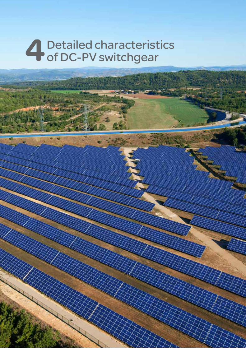
Detailed characteristics of DC-PV switchgear 4
2
Safe and reliable photovoltaic energy generation
226
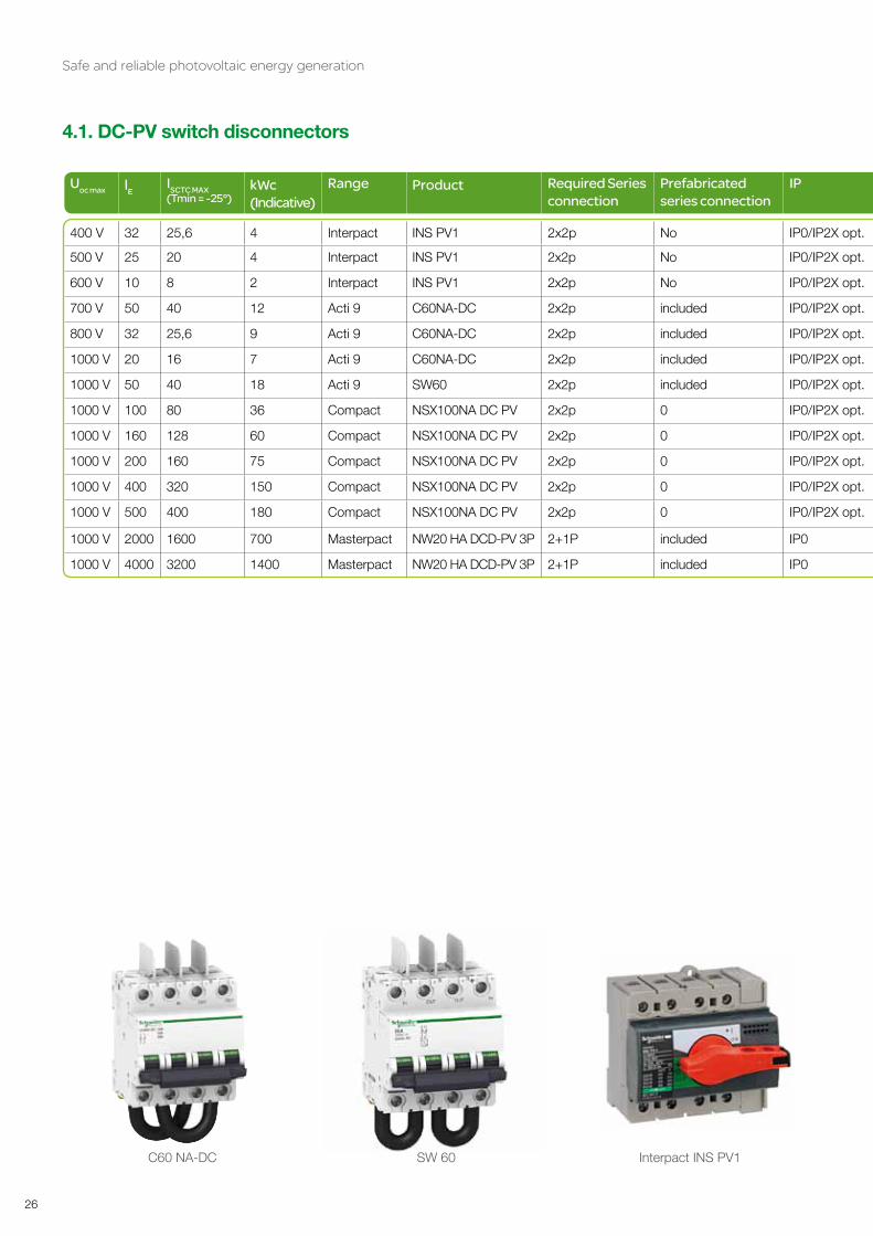
4.1. DC-PV switch disconnectors
Uoc max lE ISCTC MAX (Tmin = -25°)
kWc (Indicative)
Range Product Required Series connection
Prefabricatedseries connection
IP UIMP Degree ofpollution
Utilization category
Mechanical durability
Electrical durability
IE MAX ITH 25° ITH 40° Polarised Suitability for
isolation
400 V 32 25,6 4 Interpact INS PV1 2x2p No IP0/IP2X opt. 8 kV III DC21B 1 700 300 32 32 32 NO yES
500 V 25 20 4 Interpact INS PV1 2x2p No IP0/IP2X opt. 8 kV III DC21B 1 700 300 25 32 32 NO yES
600 V 10 8 2 Interpact INS PV1 2x2p No IP0/IP2X opt. 8 kV III DC21B 1 700 300 10 32 32 NO yES
700 V 50 40 12 Acti 9 C60NA-DC 2x2p included IP0/IP2X opt. 6 kV II DC21B 20 000 300 50 40 NO yES
800 V 32 25,6 9 Acti 9 C60NA-DC 2x2p included IP0/IP2X opt. 6 kV II DC21B 20 000 300 50 40 NO yES
1000 V 20 16 7 Acti 9 C60NA-DC 2x2p included IP0/IP2X opt. 6 kV II DC21A 20 000 1 500 50 40 NO yES
1000 V 50 40 18 Acti 9 SW60 2x2p included IP0/IP2X opt. 6 kV II DC21A 20 000 1 500 50 50 yES yES
1000 V 100 80 36 Compact NSX100NA DC PV 2x2p 0 IP0/IP2X opt. 8 kV III DC22A 50 000 1 500 100 NO yES
1000 V 160 128 60 Compact NSX100NA DC PV 2x2p 0 IP0/IP2X opt. 8 kV III DC22A 50 000 1 000 160 NO yES
1000 V 200 160 75 Compact NSX100NA DC PV 2x2p 0 IP0/IP2X opt. 8 kV III DC22A 40 000 1 000 200 NO yES
1000 V 400 320 150 Compact NSX100NA DC PV 2x2p 0 IP0/IP2X opt. 8 kV III DC22A 15 000 1 000 400 NO yES
1000 V 500 400 180 Compact NSX100NA DC PV 2x2p 0 IP0/IP2X opt. 8 kV III DC22A 15 000 1 000 500 NO yES
1000 V 2000 1600 700 Masterpact NW20 HA DCD-PV 3P 2+1P included IP0 12 kV IV DC23A 10 000 2 000 2000 NO yES
1000 V 4000 3200 1400 Masterpact NW20 HA DCD-PV 3P 2+1P included IP0 12 kV IV DC23A 10 000 2 000 4000 NO yES
C60 NA-DC SW 60 Interpact INS PV1

Safe and reliable photovoltaic energy generation
27
Uoc max lE ISCTC MAX (Tmin = -25°)
kWc (Indicative)
Range Product Required Series connection
Prefabricatedseries connection
IP UIMP Degree ofpollution
Utilization category
Mechanical durability
Electrical durability
IE MAX ITH 25° ITH 40° Polarised Suitability for
isolation
400 V 32 25,6 4 Interpact INS PV1 2x2p No IP0/IP2X opt. 8 kV III DC21B 1 700 300 32 32 32 NO yES
500 V 25 20 4 Interpact INS PV1 2x2p No IP0/IP2X opt. 8 kV III DC21B 1 700 300 25 32 32 NO yES
600 V 10 8 2 Interpact INS PV1 2x2p No IP0/IP2X opt. 8 kV III DC21B 1 700 300 10 32 32 NO yES
700 V 50 40 12 Acti 9 C60NA-DC 2x2p included IP0/IP2X opt. 6 kV II DC21B 20 000 300 50 40 NO yES
800 V 32 25,6 9 Acti 9 C60NA-DC 2x2p included IP0/IP2X opt. 6 kV II DC21B 20 000 300 50 40 NO yES
1000 V 20 16 7 Acti 9 C60NA-DC 2x2p included IP0/IP2X opt. 6 kV II DC21A 20 000 1 500 50 40 NO yES
1000 V 50 40 18 Acti 9 SW60 2x2p included IP0/IP2X opt. 6 kV II DC21A 20 000 1 500 50 50 yES yES
1000 V 100 80 36 Compact NSX100NA DC PV 2x2p 0 IP0/IP2X opt. 8 kV III DC22A 50 000 1 500 100 NO yES
1000 V 160 128 60 Compact NSX100NA DC PV 2x2p 0 IP0/IP2X opt. 8 kV III DC22A 50 000 1 000 160 NO yES
1000 V 200 160 75 Compact NSX100NA DC PV 2x2p 0 IP0/IP2X opt. 8 kV III DC22A 40 000 1 000 200 NO yES
1000 V 400 320 150 Compact NSX100NA DC PV 2x2p 0 IP0/IP2X opt. 8 kV III DC22A 15 000 1 000 400 NO yES
1000 V 500 400 180 Compact NSX100NA DC PV 2x2p 0 IP0/IP2X opt. 8 kV III DC22A 15 000 1 000 500 NO yES
1000 V 2000 1600 700 Masterpact NW20 HA DCD-PV 3P 2+1P included IP0 12 kV IV DC23A 10 000 2 000 2000 NO yES
1000 V 4000 3200 1400 Masterpact NW20 HA DCD-PV 3P 2+1P included IP0 12 kV IV DC23A 10 000 2 000 4000 NO yES
Compact NSX 200 NA DC PV Masterpact NW 20 HA DCD-PV

2
Safe and reliable photovoltaic energy generation
228
4.2. DC-PV switch disconnectors - accessories
Range Product Reference (without accesories)
Serial connection for poles
Top terminal shields
Bottom terminal shields
Level /Togle
Direct front rotary handle
Extended front rotaryhandle
Remoteopening
Remoteopen / close
Aux.contacts
Interpact INS PV1 28907
Acti 9 C60NA-DC A9N61690 Included
Acti 9 SW60 A9N61690 Included
Compact NSX100NA DC PV LV438100 Mandatory 2x LV438328
LV438327 or Interphase barrier1x LV429329
LV429518 orInterphase barriers3x LV429329
Compact NSX160NA DC PV LV438160 Mandatory 2x LV438328
LV438327 or Interphase barrier1x LV429329
LV429518 orInterphase barriers3x LV429329
Compact NSX200NA DC PV LV438250 Mandatory 2x LV438328 or 2X LV438339
LV438327 or Interphase barrier1x LV429329
LV429518 orInterphase barriers3x LV429329
Compact NSX400NA DC PV LV438300 Mandatory 2x LV438338
LV438337 orInterphase barrier1x LV432570
LV432594 orInterphase barriers3x LV432570
Compact NSX500NA DC PV LV438500 Mandatory 2x LV438338
LV438337 orInterphase barrier1x LV432570
LV432594 orInterphase barriers3x LV432570
Masterpact NW20 HA DCD-PV 3P Consult us OF
Masterpact NW20 HA DCD-PV 3P Consult us OF
MN/MX remote opening accessory for Acti 9 range
MCH remote O/C accessory for Masterpact range
Direct rotary handle accessory for Compact NSX range

Safe and reliable photovoltaic energy generation
29
Range Product Reference (without accesories)
Serial connection for poles
Top terminal shields
Bottom terminal shields
Level /Togle
Direct front rotary handle
Extended front rotaryhandle
Remoteopening
Remoteopen / close
Aux.contacts
Interpact INS PV1 28907
Acti 9 C60NA-DC A9N61690 Included
Acti 9 SW60 A9N61690 Included
Compact NSX100NA DC PV LV438100 Mandatory 2x LV438328
LV438327 or Interphase barrier1x LV429329
LV429518 orInterphase barriers3x LV429329
Compact NSX160NA DC PV LV438160 Mandatory 2x LV438328
LV438327 or Interphase barrier1x LV429329
LV429518 orInterphase barriers3x LV429329
Compact NSX200NA DC PV LV438250 Mandatory 2x LV438328 or 2X LV438339
LV438327 or Interphase barrier1x LV429329
LV429518 orInterphase barriers3x LV429329
Compact NSX400NA DC PV LV438300 Mandatory 2x LV438338
LV438337 orInterphase barrier1x LV432570
LV432594 orInterphase barriers3x LV432570
Compact NSX500NA DC PV LV438500 Mandatory 2x LV438338
LV438337 orInterphase barrier1x LV432570
LV432594 orInterphase barriers3x LV432570
Masterpact NW20 HA DCD-PV 3P Consult us OF
Masterpact NW20 HA DCD-PV 3P Consult us OF
Extended rotary handle accessory for Compact NSX range
2
Safe and reliable photovoltaic energy generation
230
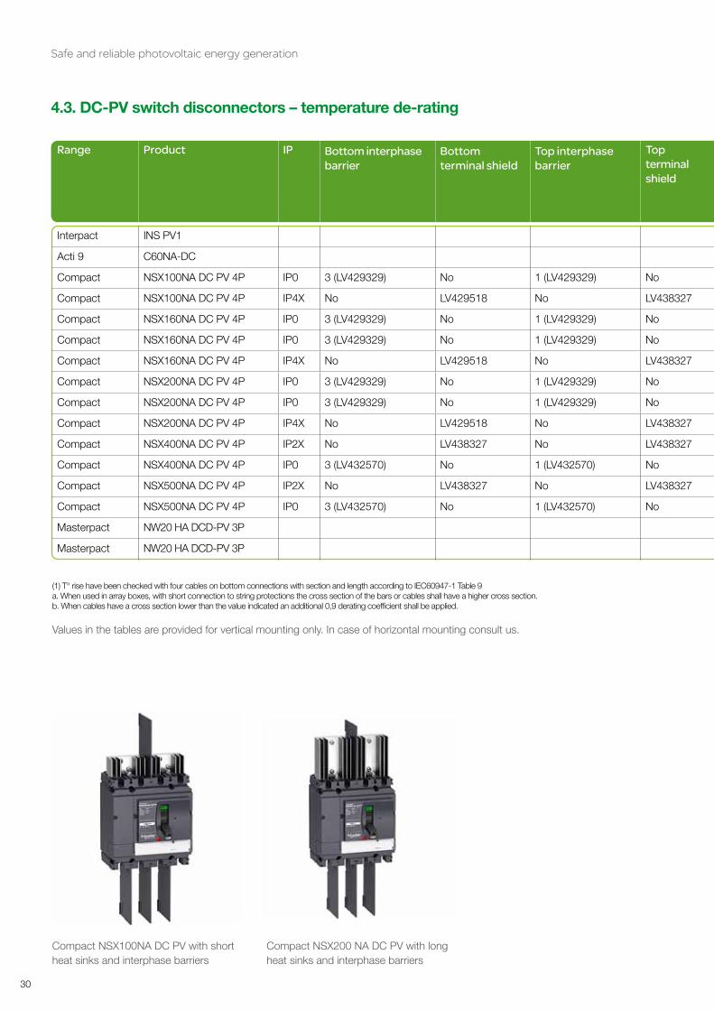
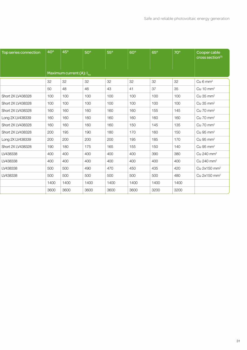
4.3. DC-PV switch disconnectors – temperature de-rating
Range Product IP Bottom interphase barrier
Bottom terminal shield
Top interphase barrier
Top terminal shield
Top series connection 40° 45° 50° 55° 60° 65° 70° Cooper cablecross section(1)
Maximum current (A): ITH
Interpact INS PV1 32 32 32 32 32 32 32 Cu 6 mm2
Acti 9 C60NA-DC 50 48 46 43 41 37 35 Cu 10 mm2
Compact NSX100NA DC PV 4P IP0 3 (LV429329) No 1 (LV429329) No Short 2X LV438328 100 100 100 100 100 100 100 Cu 35 mm2
Compact NSX100NA DC PV 4P IP4X No LV429518 No LV438327 Short 2X LV438328 100 100 100 100 100 100 100 Cu 35 mm2
Compact NSX160NA DC PV 4P IP0 3 (LV429329) No 1 (LV429329) No Short 2X LV438328 160 160 160 160 160 155 145 Cu 70 mm2
Compact NSX160NA DC PV 4P IP0 3 (LV429329) No 1 (LV429329) No Long 2X LV438339 160 160 160 160 160 160 160 Cu 70 mm2
Compact NSX160NA DC PV 4P IP4X No LV429518 No LV438327 Short 2X LV438328 160 160 160 160 150 145 135 Cu 70 mm2
Compact NSX200NA DC PV 4P IP0 3 (LV429329) No 1 (LV429329) No Short 2X LV438328 200 195 190 180 170 160 150 Cu 95 mm2
Compact NSX200NA DC PV 4P IP0 3 (LV429329) No 1 (LV429329) No Long 2X LV438339 200 200 200 200 195 185 170 Cu 95 mm2
Compact NSX200NA DC PV 4P IP4X No LV429518 No LV438327 Short 2X LV438328 190 180 175 165 155 150 140 Cu 95 mm2
Compact NSX400NA DC PV 4P IP2X No LV438327 No LV438327 LV438338 400 400 400 400 400 390 380 Cu 240 mm2
Compact NSX400NA DC PV 4P IP0 3 (LV432570) No 1 (LV432570) No LV438338 400 400 400 400 400 400 400 Cu 240 mm2
Compact NSX500NA DC PV 4P IP2X No LV438327 No LV438327 LV438338 500 500 490 470 450 435 420 Cu 2x150 mm2
Compact NSX500NA DC PV 4P IP0 3 (LV432570) No 1 (LV432570) No LV438338 500 500 500 500 500 500 480 Cu 2x150 mm2
Masterpact NW20 HA DCD-PV 3P 1400 1400 1400 1400 1400 1400 1400
Masterpact NW20 HA DCD-PV 3P 3600 3600 3600 3600 3600 3200 3200
(1) T° rise have been checked with four cables on bottom connections with section and length according to IEC60947-1 Table 9a. When used in array boxes, with short connection to string protections the cross section of the bars or cables shall have a higher cross section.b. When cables have a cross section lower than the value indicated an additional 0,9 derating coefficient shall be applied.
Values in the tables are provided for vertical mounting only. In case of horizontal mounting consult us.
Compact NSX100NA DC PV with short heat sinks and interphase barriers
Compact NSX200 NA DC PV with long heat sinks and interphase barriers
Safe and reliable photovoltaic energy generation
31
Range Product IP Bottom interphase barrier
Bottom terminal shield
Top interphase barrier
Top terminal shield
Top series connection 40° 45° 50° 55° 60° 65° 70° Cooper cablecross section(1)
Maximum current (A): ITH
Interpact INS PV1 32 32 32 32 32 32 32 Cu 6 mm2
Acti 9 C60NA-DC 50 48 46 43 41 37 35 Cu 10 mm2
Compact NSX100NA DC PV 4P IP0 3 (LV429329) No 1 (LV429329) No Short 2X LV438328 100 100 100 100 100 100 100 Cu 35 mm2
Compact NSX100NA DC PV 4P IP4X No LV429518 No LV438327 Short 2X LV438328 100 100 100 100 100 100 100 Cu 35 mm2
Compact NSX160NA DC PV 4P IP0 3 (LV429329) No 1 (LV429329) No Short 2X LV438328 160 160 160 160 160 155 145 Cu 70 mm2
Compact NSX160NA DC PV 4P IP0 3 (LV429329) No 1 (LV429329) No Long 2X LV438339 160 160 160 160 160 160 160 Cu 70 mm2
Compact NSX160NA DC PV 4P IP4X No LV429518 No LV438327 Short 2X LV438328 160 160 160 160 150 145 135 Cu 70 mm2
Compact NSX200NA DC PV 4P IP0 3 (LV429329) No 1 (LV429329) No Short 2X LV438328 200 195 190 180 170 160 150 Cu 95 mm2
Compact NSX200NA DC PV 4P IP0 3 (LV429329) No 1 (LV429329) No Long 2X LV438339 200 200 200 200 195 185 170 Cu 95 mm2
Compact NSX200NA DC PV 4P IP4X No LV429518 No LV438327 Short 2X LV438328 190 180 175 165 155 150 140 Cu 95 mm2
Compact NSX400NA DC PV 4P IP2X No LV438327 No LV438327 LV438338 400 400 400 400 400 390 380 Cu 240 mm2
Compact NSX400NA DC PV 4P IP0 3 (LV432570) No 1 (LV432570) No LV438338 400 400 400 400 400 400 400 Cu 240 mm2
Compact NSX500NA DC PV 4P IP2X No LV438327 No LV438327 LV438338 500 500 490 470 450 435 420 Cu 2x150 mm2
Compact NSX500NA DC PV 4P IP0 3 (LV432570) No 1 (LV432570) No LV438338 500 500 500 500 500 500 480 Cu 2x150 mm2
Masterpact NW20 HA DCD-PV 3P 1400 1400 1400 1400 1400 1400 1400
Masterpact NW20 HA DCD-PV 3P 3600 3600 3600 3600 3600 3200 3200

2
Safe and reliable photovoltaic energy generation
232
4.4. DC-PV overcurrent protection
In A ISCTC MAX (Tmin = -25°)
kW (Indicative) Range Product PrefabricatedSeries connection
IP Uoc max UIMPDegree ofPollution
lTH 25 ° lTH 40 ° ICURequired Series connection
Polarised Suitability for isolation
≤ 25 TeSys DF101PV (10x38) NA IIP20 1 000 V 6 kV II 32 1 DF101 /polarity NO yES
1 0,8 0,25 Acti 9 C60DC-PV included IP0/IP2X opt. 800 V 6 kV II 1 1.5 kA 2x2p NO yES
2 1,6 0,5 Acti 9 C60DC-PV included IP0/IP2X opt. 800 V 6 kV II 2 1.5 kA 2x2p NO yES
3 2,4 0,8 Acti 9 C60DC-PV included IP0/IP2X opt. 800 V 6 kV II 3 1.5 kA 2x2p NO yES
5 4 1,3 Acti 9 C60DC-PV included IP0/IP2X opt. 800 V 6 kV II 5 1.5 kA 2x2p NO yES
8 6,4 2 Acti 9 C60DC-PV included IP0/IP2X opt. 800 V 6 kV II 8 1.5 kA 2x2p NO yES
10 88 2,6 Acti 9 C60DC-PV included IP0/IP2X opt. 800 V 6 kV II 10 1.5 kA 2x2p NO yES
13 10 3,5 Acti 9 C60DC-PV included IP0/IP2X opt. 800 V 6 kV II 13 1.5 kA 2x2p NO yES
15 12 4 Acti 9 C60DC-PV included IP0/IP2X opt. 800 V 6 kV II 15 1.5 kA 2x2p NO yES
16 12,8 4,3 Acti 9 C60DC-PV included IP0/IP2X opt. 800 V 6 kV II 16 1.5 kA 2x2p NO yES
20 16 5 Acti 9 C60DC-PV included IP0/IP2X opt. 800 V 6 kV II 20 1.5 kA 2x2p NO yES
25 20 8 Acti 9 C60DC-PV included IP0/IP2X opt. 800 V 6 kV II 25 1.5 kA 2x2p NO yES
80 63 33 Compact NSX80 TM DC PV Mandatory IP4X 1 000 V 8 kV III 80 10 kA 2x2p NO yES
125 100 45 Compact NSX80 TM DC PV Mandatory IP4X 1 000 V 8 kV III 100 10 kA 2x2p NO yES
160 125 53 Compact NSX125 TM DC PV Mandatory IP4X 1 000 V 8 kV III 160 10 kA 2x2p NO yES
200 160 67 Compact NSX200 TM DC PV Mandatory IP4X 1 000 V 8 kV III 200 10 kA 2x2p NO yES
TeSys DF101PV fuse carrier C60 PV-DC modular circuit breaker Compact NSX200 TM DC PV with terminal shields

Safe and reliable photovoltaic energy generation
33
In A ISCTC MAX (Tmin = -25°)
kW (Indicative) Range Product PrefabricatedSeries connection
IP Uoc max UIMPDegree ofPollution
lTH 25 ° lTH 40 ° ICURequired Series connection
Polarised Suitability for isolation
≤ 25 TeSys DF101PV (10x38) NA IIP20 1 000 V 6 kV II 32 1 DF101 /polarity NO yES
1 0,8 0,25 Acti 9 C60DC-PV included IP0/IP2X opt. 800 V 6 kV II 1 1.5 kA 2x2p NO yES
2 1,6 0,5 Acti 9 C60DC-PV included IP0/IP2X opt. 800 V 6 kV II 2 1.5 kA 2x2p NO yES
3 2,4 0,8 Acti 9 C60DC-PV included IP0/IP2X opt. 800 V 6 kV II 3 1.5 kA 2x2p NO yES
5 4 1,3 Acti 9 C60DC-PV included IP0/IP2X opt. 800 V 6 kV II 5 1.5 kA 2x2p NO yES
8 6,4 2 Acti 9 C60DC-PV included IP0/IP2X opt. 800 V 6 kV II 8 1.5 kA 2x2p NO yES
10 88 2,6 Acti 9 C60DC-PV included IP0/IP2X opt. 800 V 6 kV II 10 1.5 kA 2x2p NO yES
13 10 3,5 Acti 9 C60DC-PV included IP0/IP2X opt. 800 V 6 kV II 13 1.5 kA 2x2p NO yES
15 12 4 Acti 9 C60DC-PV included IP0/IP2X opt. 800 V 6 kV II 15 1.5 kA 2x2p NO yES
16 12,8 4,3 Acti 9 C60DC-PV included IP0/IP2X opt. 800 V 6 kV II 16 1.5 kA 2x2p NO yES
20 16 5 Acti 9 C60DC-PV included IP0/IP2X opt. 800 V 6 kV II 20 1.5 kA 2x2p NO yES
25 20 8 Acti 9 C60DC-PV included IP0/IP2X opt. 800 V 6 kV II 25 1.5 kA 2x2p NO yES
80 63 33 Compact NSX80 TM DC PV Mandatory IP4X 1 000 V 8 kV III 80 10 kA 2x2p NO yES
125 100 45 Compact NSX80 TM DC PV Mandatory IP4X 1 000 V 8 kV III 100 10 kA 2x2p NO yES
160 125 53 Compact NSX125 TM DC PV Mandatory IP4X 1 000 V 8 kV III 160 10 kA 2x2p NO yES
200 160 67 Compact NSX200 TM DC PV Mandatory IP4X 1 000 V 8 kV III 200 10 kA 2x2p NO yES

2
Safe and reliable photovoltaic energy generation
234
4.5. DC-PV overcurrent protection - accessories
Range Product Réf (without accessories) Serial connection for pole Top terminal shields
Bottom terminal shields
Level / Toggle Direct front rotary handle
Extended front rotary handle
Remote opening
Remote open/close
Aux.contacts
TeSys DF101PV (10x38) DF101PV
Acti 9 C60PV-DC 1A A9N61653 Included
Acti 9 C60PV-DC 2A A9N61654 Included
Acti 9 C60PV-DC 3A A9N61655 Included
Acti 9 C60PV-DC 5A A9N61656 Included
Acti 9 C60PV-DC 8A A9N61657 Included
Acti 9 C60PV-DC 10A A9N61650 Included
Acti 9 C60PV-DC 13A A9N61658 Included
Acti 9 C60PV-DC 15A A9N61659 Included
Acti 9 C60PV-DC 16A A9N61651 Included
Acti 9 C60PV-DC 20A A9N61652 Included
Acti 9 C60PV-DC 25A A9N61660 Included
Compact NSX80 TM DC PV LV438081 Mandatory 2x LV438328
Mandatory 2x LV438327
Mandatory 2x LV429518
Compact NSX125 TM DC PV LV438126 Mandatory 2x LV438328
Mandatory 2x LV438327
Mandatory 2x LV429518
Compact NSX160 TM DC PV LV438161 Mandatory 2x LV438328
Mandatory 2x LV438327
Mandatory 2x LV429518
Compact NSX200 TM DC PV LV438201 Mandatory 2x LV438328
Mandatory 2x LV438327
Mandatory 2x LV429518
Insulation of live partsTerminal shieldsTerminal shields are sealable insulating accessories that protect against direct contact with power circuits. They deliver protection levels IP40 and IK07. Terminal shields are mandatory for Compact NSX DC PV circuit breakers, and for voltages where UDC = 500 V.
C60 DC-PV with interphase barriers Zoom on heat sinks and terminal shields for Compact NSX DC PV
Compact NSX200 TM DC PV with terminal shields

Safe and reliable photovoltaic energy generation
35
Range Product Réf (without accessories) Serial connection for pole Top terminal shields
Bottom terminal shields
Level / Toggle Direct front rotary handle
Extended front rotary handle
Remote opening
Remote open/close
Aux.contacts
TeSys DF101PV (10x38) DF101PV
Acti 9 C60PV-DC 1A A9N61653 Included
Acti 9 C60PV-DC 2A A9N61654 Included
Acti 9 C60PV-DC 3A A9N61655 Included
Acti 9 C60PV-DC 5A A9N61656 Included
Acti 9 C60PV-DC 8A A9N61657 Included
Acti 9 C60PV-DC 10A A9N61650 Included
Acti 9 C60PV-DC 13A A9N61658 Included
Acti 9 C60PV-DC 15A A9N61659 Included
Acti 9 C60PV-DC 16A A9N61651 Included
Acti 9 C60PV-DC 20A A9N61652 Included
Acti 9 C60PV-DC 25A A9N61660 Included
Compact NSX80 TM DC PV LV438081 Mandatory 2x LV438328
Mandatory 2x LV438327
Mandatory 2x LV429518
Compact NSX125 TM DC PV LV438126 Mandatory 2x LV438328
Mandatory 2x LV438327
Mandatory 2x LV429518
Compact NSX160 TM DC PV LV438161 Mandatory 2x LV438328
Mandatory 2x LV438327
Mandatory 2x LV429518
Compact NSX200 TM DC PV LV438201 Mandatory 2x LV438328
Mandatory 2x LV438327
Mandatory 2x LV429518

2
Safe and reliable photovoltaic energy generation
236
4.6. DC-PV overcurrent protection – temperature de-rating
Range Product 20 ° 25 ° 30 ° 35 ° 40 ° 45 ° 50 ° 55 ° 60 ° 65 ° 70 °
TeSys DF101PV(10x38) 32 31 30 29 28 27 25 23 22 21 20
Acti 9 C60 DC-PV 1A 1,02 1 0,98 0,96 0,94 0,92 0,9 0,88 0,86 0,84 0,82
Acti 9 C60 DC-PV 2A 2,06 2 1,94 1,88 1,82 1,76 1,7 1,63 1,56 1,48 1,41
Acti 9 C60 DC-PV 3A 3,08 3 2,92 2,84 2,75 2,66 2,57 2,48 2,38 2,27 2,17
Acti 9 C60 DC-PV 5A 5,1 5 4,9 4,8 4,69 4,58 4,47 4,36 4,24 4,12 4
Acti 9 C60 DC-PV 8A 8,16 8 7,83 7,67 7,49 7,31 7,13 6,95 6,76 6,56 6,36
Acti 9 C60 DC-PV 10A 10,3 10 9,7 9,4 9,2 8,9 8,6 8,2 7,9 7,6 7,2
Acti 9 C60 DC-PV 13A 13,2 13 12,7 12,5 12,2 12 11,7 11,4 11,1 10,8 10,5
Acti 9 C60 DC-PV 15A 15,4 15 14,6 14,3 13,9 13,5 13 12,6 12,2 11,7 11,2
Acti 9 C60 DC-PV 16A 16,3 16 15,7 15,3 14,9 14,6 14,2 13,8 13,4 13 12,5
Acti 9 C60 DC-PV 20A 20,4 20 19,6 19,2 18,7 18,3 17,9 17,4 16,9 16,4 15,9
Acti 9 C60 DC-PV 25A 25,5 25 24,5 23,9 23,3 22,7 22,1 20,9 20,2 19,6 15,9
Compact NSX80 TM DC PV 88 86 84 82 80 77 75 72 69 66 63 Cu 25 mm2
Compact NSX125 TM DC PV 137,5 135 131 128 125 121 116 112 108 103 98 Cu 50 mm2
Compact NSX160 TM DC PV 176 172 168 164 160 153 147 142 136 130 118 Cu 70 mm2
Compact NSX200 TM DC PV Consult us
For Compact NSX the overload protection is calibrated at 40 °C and for C60 DC-PV at 20 °C. This means that when the ambient temperature is less or greater than these temperatures, the Ir protection pickupis slightly modified.
• T° rise for Compact range have been checked with terminal shields (mandatory) heat sink on top, four cables on bottom connections with section and length according to IEC60947-1 Table 9,
• Values in the tables are provided for vertical mounting only. In case of horizontal mounting consult us. To obtain the tripping time for a given temperature:
- see the tripping curves for 20 or 40 °C - determine tripping times corresponding to the Ir value (thermal setting on
the device), corrected for the breaker ambient temperature as indicated in the tables below.
- T° rise for Compact range have been checked with t erminal shields (mandatory) heat sink on top, four cables on bottom connections with section and length according to IEC60947-1 Table 9,
- Values in the tables are provided for vertical mounting only, in case of horizontal mounting consult us.

Safe and reliable photovoltaic energy generation
37
Range Product 20 ° 25 ° 30 ° 35 ° 40 ° 45 ° 50 ° 55 ° 60 ° 65 ° 70 °
TeSys DF101PV(10x38) 32 31 30 29 28 27 25 23 22 21 20
Acti 9 C60 DC-PV 1A 1,02 1 0,98 0,96 0,94 0,92 0,9 0,88 0,86 0,84 0,82
Acti 9 C60 DC-PV 2A 2,06 2 1,94 1,88 1,82 1,76 1,7 1,63 1,56 1,48 1,41
Acti 9 C60 DC-PV 3A 3,08 3 2,92 2,84 2,75 2,66 2,57 2,48 2,38 2,27 2,17
Acti 9 C60 DC-PV 5A 5,1 5 4,9 4,8 4,69 4,58 4,47 4,36 4,24 4,12 4
Acti 9 C60 DC-PV 8A 8,16 8 7,83 7,67 7,49 7,31 7,13 6,95 6,76 6,56 6,36
Acti 9 C60 DC-PV 10A 10,3 10 9,7 9,4 9,2 8,9 8,6 8,2 7,9 7,6 7,2
Acti 9 C60 DC-PV 13A 13,2 13 12,7 12,5 12,2 12 11,7 11,4 11,1 10,8 10,5
Acti 9 C60 DC-PV 15A 15,4 15 14,6 14,3 13,9 13,5 13 12,6 12,2 11,7 11,2
Acti 9 C60 DC-PV 16A 16,3 16 15,7 15,3 14,9 14,6 14,2 13,8 13,4 13 12,5
Acti 9 C60 DC-PV 20A 20,4 20 19,6 19,2 18,7 18,3 17,9 17,4 16,9 16,4 15,9
Acti 9 C60 DC-PV 25A 25,5 25 24,5 23,9 23,3 22,7 22,1 20,9 20,2 19,6 15,9
Compact NSX80 TM DC PV 88 86 84 82 80 77 75 72 69 66 63 Cu 25 mm2
Compact NSX125 TM DC PV 137,5 135 131 128 125 121 116 112 108 103 98 Cu 50 mm2
Compact NSX160 TM DC PV 176 172 168 164 160 153 147 142 136 130 118 Cu 70 mm2
Compact NSX200 TM DC PV Consult us

2
Safe and reliable photovoltaic energy generation
238
Safe and reliable photovoltaic energy generation
39
Solar photovoltaic (PV) solar power has asserted itself as a clean, convenient alternative power source that is versatile and cheap to run. It is nevertheless a relative newcomer in the field of power generation – both for grid-connected and stand-alone applications. As such its operating technology is still evolving, as are the installation and safety standards governing it.
Of paramount importance to the industry are the hazards for fire fighters and emergency service workers posed by building-mounted projects – thought to account for 55% of the European PV market. The DC voltage levels of PV generators, allied to fact that they cannot be interrupted as long as the sun is shining and that their short-circuit current is too weak to trip the disconnect switch, are issues like the safety of firefighters that shall be addressed. New standards are being developed, as are recommendations for good installation practices. In other words, standards are evolving. In the meantime, however, the best way to ensure normal operating safety is to select, install, and secure systems in accordance with manufacturer’s instructions and IEC 60364 standard including part 60364-712.
Insulation monitoring solution and overcurrent protection, shall be selected to ensure safety taking into account the high level of voltage and the particular risk of double earth fault
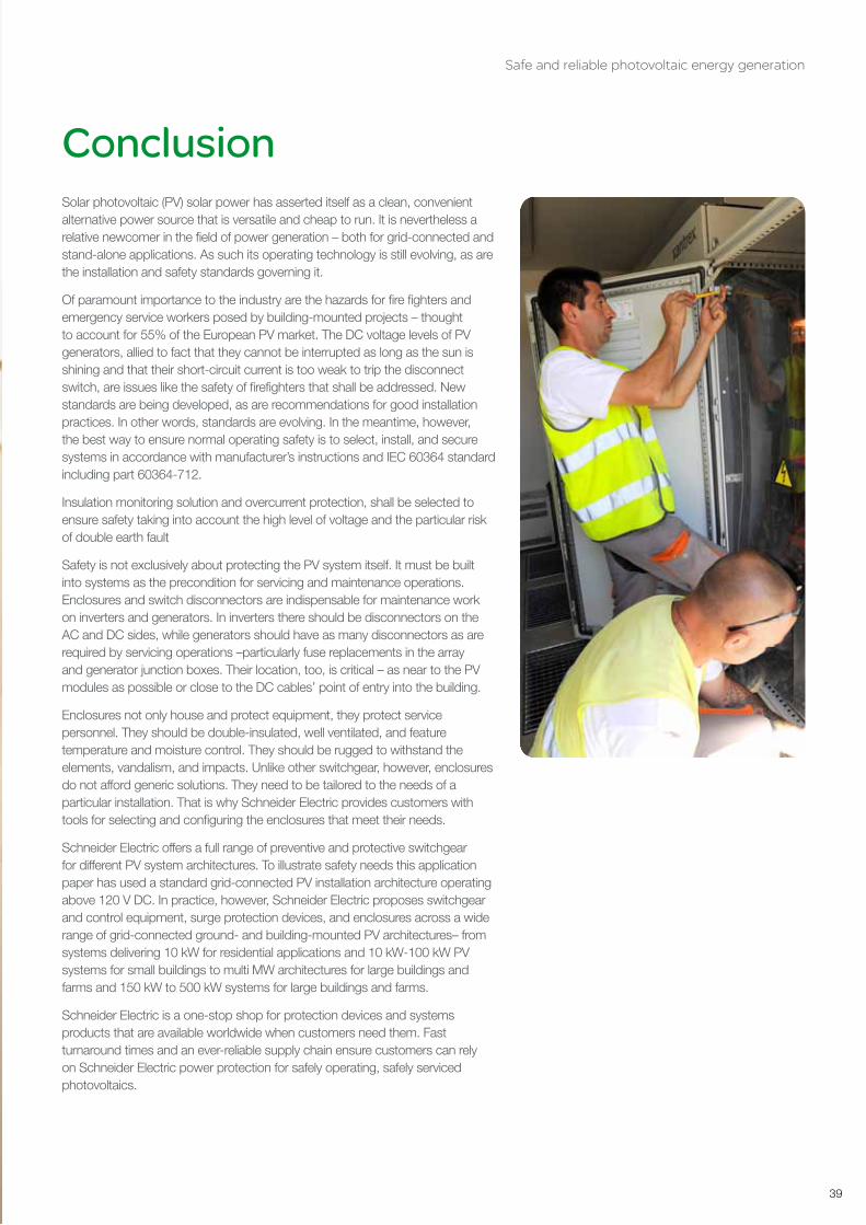
Safety is not exclusively about protecting the PV system itself. It must be built into systems as the precondition for servicing and maintenance operations. Enclosures and switch disconnectors are indispensable for maintenance work on inverters and generators. In inverters there should be disconnectors on the AC and DC sides, while generators should have as many disconnectors as are required by servicing operations –particularly fuse replacements in the array and generator junction boxes. Their location, too, is critical – as near to the PV modules as possible or close to the DC cables’ point of entry into the building.
Enclosures not only house and protect equipment, they protect service personnel. They should be double-insulated, well ventilated, and feature temperature and moisture control. They should be rugged to withstand the elements, vandalism, and impacts. Unlike other switchgear, however, enclosures do not afford generic solutions. They need to be tailored to the needs of a particular installation. That is why Schneider Electric provides customers with tools for selecting and configuring the enclosures that meet their needs.
Schneider Electric offers a full range of preventive and protective switchgear for different PV system architectures. To illustrate safety needs this application paper has used a standard grid-connected PV installation architecture operating above 120 V DC. In practice, however, Schneider Electric proposes switchgear and control equipment, surge protection devices, and enclosures across a wide range of grid-connected ground- and building-mounted PV architectures– from systems delivering 10 kW for residential applications and 10 kW-100 kW PV systems for small buildings to multi MW architectures for large buildings and farms and 150 kW to 500 kW systems for large buildings and farms.
Schneider Electric is a one-stop shop for protection devices and systems products that are available worldwide when customers need them. Fast turnaround times and an ever-reliable supply chain ensure customers can rely on Schneider Electric power protection for safely operating, safely serviced photovoltaics.
Conclusion

2
Safe and reliable photovoltaic energy generation
240
Definition (Ref IEC 60364-7-712)
PV module Smallest completely environmentally protected assembly of interconnected PV cells
PV string Circuit in which PV modules are connected in series, in order for a PV array to generate the required output voltage
PV arrayMechanically and electrically integrated assembly of PV modules, and other necessary components, to form a d.c. power supply unit
PV array junction boxEnclosure where all PV strings of any PV array are electrically connected and where protective devices can be located if necessary
PV generatorAssembly of PV arrays connected in parallel to one input of the inverter where one MPPT function is associated with
PV generator junction boxEnclosure where all PV arrays are electrically connected and where protection devices can be located if necessary
PV string cableAdditional cable, not provided with the PV modules, for interconnecting a PV string until a PV junction box
PV array cableOutput cable of a PV array
PV d.c. main cable Cable connecting the PV generator junction box to the d.c. terminals of the PV inverter
PV inverterDevice which converts d.c. voltage and d.c. current of the PV generator into a.c. voltage and a.c. current
PV a.c. supply circuitCircuit connecting the a.c. terminals of the PV inverter to the designated distribution board of the electrical installation
PV a.c. moduleIntegrated module/inverter assembly where the electrical interface terminals are a.c. only. No access is provided to the d.c. side
PV installationErected equipment of a PV power supply system
PV electrical installationThe electrical installation of a PV system starts from a PV module or a set of PV modules connected in series with their own cables (provided by the PV module manufacturer), up to a distribution network or to a customer installation
Standard test conditions (STC) Test conditions specified in IEC 60904-3 for PV cells and PV modules

Safe and reliable photovoltaic energy generation
41
Open-circuit voltage under standard test conditions UOC STCVoltage under standard test conditions across an unloaded (open) PV module, PV string, PV array, PV generator or on the d.c. side of the PV inverter
Open-circuit maximum voltage UOC MAXMaximum voltage across an unloaded (open) PV module, PV string, PV array, PV generator or on the d.c. side of the PV inverter
Short-circuit current under standard test conditions ISC STCShort-circuit current of a PV module, PV string, PV array or PV generator under standard test conditions
ISC MODThe short circuit current of a PV module or PV string at Standard Test Conditions (STC), as specified by the manufacturer in the product specification plate
ISC ARRAYThe short circuit current of the PV array at Standard Test Conditions, and is equal to: ISC ARRAy = ISC MOD x SA where SA is the total number of parallel-connected PV strings in the PV array
ITRIPThe nominal rating of an overcurrent protection device.
Short-circuit maximum current ISC MAXMaximum short-circuit current of a PV module, PV string, PV array or PV generator
Maximum reverse current IRMDefines the thermal PV module withstand capability under the test reverse current value ITEST = 1,35 IRM during 2 hours, as defined in standard IEC 61730-2 to determine the acceptability of the risk of fire
d.c. sidePart of a PV installation from the PV modules to the d.c. terminals of the PV inverter
a.c. sidePart of a PV installation from the a.c. terminals of the PV inverter to the point of connection of the PV supply cable to the electrical installation
Maximum power point tracking (MPPT)Internal control method of an inverter ensuring a search for operation at maximum power
NOTE As PV strings are a group of PV modules connected in series, the short circuit current of a string is equal to ISC MOD.
NOTE IRM value is given by the PV module manufacturer

2
Safe and reliable photovoltaic energy generation
242
Notes

Safe and reliable photovoltaic energy generation
43
05/2012
Make the most of your energySM
> For more information, visit www.schneider-electric.com/solar
Schneider Electric Industries SAS
Head Office35 rue Joseph Monier 92506 Rueil-Malmaison Cedex- FranceTel.: +33 (0)1 41 20 70 00www.schneider-electric.com
©2012 Schneider Electric. All Rights Reserved. Schneider Electric, Make the most of your energy, Compact, Masterpact, Interpact, Acti 9, Micrologic, Prisma, Pragma, Kaedra, Thalassa, Spacial, Tesys, Vigi are trademarks owned by Schneider Electric Industries SAS or its affiliated companies. All other trademarks are property of their respective owners.
EDCED112005EN 05/2012