safety configuration & diagnosis (scd) user...
TRANSCRIPT

R
Safety Configuration & Diagnosis (SCD)User Manual
Important User Information
Because of the variety of uses for the products described in this publication, those responsible for theapplication and use of this control equipment must satisfy themselves that all necessary steps have beentaken to assure that each application and use meets all performance and safety requirements, includingany applicable laws, regulations, codes and standards.
Reproduction of the contents of this copyrighted publication, in whole or part, without written permissionof Rockwell Automation, is prohibited.
Throughout this manual we use notes to make you aware of safety considerations:
The illustrations, charts, sample programs and layout examples shown in the guide are intended solely forpurposes of example. Since there are many variables and requirements associated with any particularinstallation, Rockwell Automation does not assume responsibility or liability (to include intellectual propertyliability) for actual use based upon the examples shown in this publication.
Rockwell Automation publication SGI-1.1, Safety Guidelines for the Application, Installation andMaintenance of Solid-State Control (available from your local Rockwell Automation sales office), describessome important differences between solid-state equipment and electromechanical devices that should betaken into consideration when applying products such as those described in this publication.
It is recommended that you save this user manual for future use.
Identifies information about practices or circumstances that can cause an explosion in a hazardous environment, which may lead to personal injury or death, property damage, or economic loss.
Identifies information that is critical for successful application and understanding of the product.
Identifies information about practices or circumstances that can lead to personal injury or death, property damage, or economic loss. Attentions help you identify a hazard, avoid a hazard, and recognize the consequences.
SHOCK HAZARD Labels may be on or inside the equipment (for example, drive or motor) to alert people that dangerous voltage may be present.
BURN HAZARD Labels may be on or inside the equipment (for example, drive or motor) to alert people that surfaces may reach dangerous temperatures.
WARNING
IMPORTANT
ATTENTION
Rockwell Automation Publication 10000455426 Ver 00 - January 2013 1
Contents
Contents
1 Product description. . . . . . . . . . . . . . . . . . . . . . . . . . . . . . . . . . . . . . . . . . . .2
2 User interface . . . . . . . . . . . . . . . . . . . . . . . . . . . . . . . . . . . . . . . . . . . . . . . . .3User interface menu bar . . . . . . . . . . . . . . . . . . . . . . . . . . . . . . . . . . . . . . . . . . . . . . . . . . . . . 4User interface toolbar . . . . . . . . . . . . . . . . . . . . . . . . . . . . . . . . . . . . . . . . . . . . . . . . . . . . . . . 4User interface navigation area . . . . . . . . . . . . . . . . . . . . . . . . . . . . . . . . . . . . . . . . . . . . . . . 5Log window . . . . . . . . . . . . . . . . . . . . . . . . . . . . . . . . . . . . . . . . . . . . . . . . . . . . . . . . . . . . . . . . 6Project tree . . . . . . . . . . . . . . . . . . . . . . . . . . . . . . . . . . . . . . . . . . . . . . . . . . . . . . . . . . . . . . . . . 6Project name. . . . . . . . . . . . . . . . . . . . . . . . . . . . . . . . . . . . . . . . . . . . . . . . . . . . . . . . . . . . . . . . 8
3 Device window . . . . . . . . . . . . . . . . . . . . . . . . . . . . . . . . . . . . . . . . . . . . . . . .9Device window menu bar . . . . . . . . . . . . . . . . . . . . . . . . . . . . . . . . . . . . . . . . . . . . . . . . . . . 9Device information area . . . . . . . . . . . . . . . . . . . . . . . . . . . . . . . . . . . . . . . . . . . . . . . . . . . .10Device window toolbar. . . . . . . . . . . . . . . . . . . . . . . . . . . . . . . . . . . . . . . . . . . . . . . . . . . . .10Device window navigation area. . . . . . . . . . . . . . . . . . . . . . . . . . . . . . . . . . . . . . . . . . . . .11Device window working area . . . . . . . . . . . . . . . . . . . . . . . . . . . . . . . . . . . . . . . . . . . . . . .12Device window status bar . . . . . . . . . . . . . . . . . . . . . . . . . . . . . . . . . . . . . . . . . . . . . . . . . .13
4 Printer setup . . . . . . . . . . . . . . . . . . . . . . . . . . . . . . . . . . . . . . . . . . . . . . . . 14
5 Validating products. . . . . . . . . . . . . . . . . . . . . . . . . . . . . . . . . . . . . . . . . . 15
6 Working with projects . . . . . . . . . . . . . . . . . . . . . . . . . . . . . . . . . . . . . . . 16Creating a new project and transferring it . . . . . . . . . . . . . . . . . . . . . . . . . . . . . . . . . . .16Using an existing project for further devices. . . . . . . . . . . . . . . . . . . . . . . . . . . . . . . . .18Creating a project for already configured devices . . . . . . . . . . . . . . . . . . . . . . . . . . .19Adding a device . . . . . . . . . . . . . . . . . . . . . . . . . . . . . . . . . . . . . . . . . . . . . . . . . . . . . . . . . . . .21Displaying the device properties. . . . . . . . . . . . . . . . . . . . . . . . . . . . . . . . . . . . . . . . . . . .22
7 Configuring a device/device cluster . . . . . . . . . . . . . . . . . . . . . . . . . . . 24Editing a configuration draft . . . . . . . . . . . . . . . . . . . . . . . . . . . . . . . . . . . . . . . . . . . . . . . .25Approving the configuration log. . . . . . . . . . . . . . . . . . . . . . . . . . . . . . . . . . . . . . . . . . . .27
8 Changing the user group . . . . . . . . . . . . . . . . . . . . . . . . . . . . . . . . . . . . . 29
9 Changing the password . . . . . . . . . . . . . . . . . . . . . . . . . . . . . . . . . . . . . . 31
10 Resetting the password . . . . . . . . . . . . . . . . . . . . . . . . . . . . . . . . . . . . . 32
11 Carrying out diagnosis . . . . . . . . . . . . . . . . . . . . . . . . . . . . . . . . . . . . . . 33
12 Entering comments. . . . . . . . . . . . . . . . . . . . . . . . . . . . . . . . . . . . . . . . . 34
13 Annex . . . . . . . . . . . . . . . . . . . . . . . . . . . . . . . . . . . . . . . . . . . . . . . . . . . . . 35List of tables . . . . . . . . . . . . . . . . . . . . . . . . . . . . . . . . . . . . . . . . . . . . . . . . . . . . . . . . . . . . . . .35List of illustrations . . . . . . . . . . . . . . . . . . . . . . . . . . . . . . . . . . . . . . . . . . . . . . . . . . . . . . . . . .35
2 Rockwell Automation Publication 10000455426 Ver 00 - January 2013
Chapter 1 Product description
Chapter 1
Product description
Depending on purpose and operating mode, devices supplied by Rockwell may be configured differently. The SCD has a graphic user interface which allows you configure and diagnose devices supplied by Rockwell. The parameters of a configuration are transferred to the devices, where they are saved.
Note The software is not suitable for the configuration and diagnostics of devices of other manufacturers.
3 Rockwell Automation Publication 10000455426 Ver 00 - January 2013
Chapter 2 User interface
Chapter 2
User interface
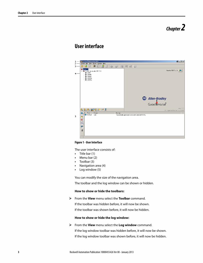
Figure 1 - User Interface
The user interface consists of:• Title bar (1)• Menu bar (2)• Toolbar (3)• Navigation area (4)• Log window (5)
You can modify the size of the navigation area.
The toolbar and the log window can be shown or hidden.
How to show or hide the toolbars:
From the View menu select the Toolbar command.
If the toolbar was hidden before, it will now be shown.
If the toolbar was shown before, it will now be hidden.
How to show or hide the log window:
From the View menu select the Log window command.
If the log window toolbar was hidden before, it will now be shown.
If the log window toolbar was shown before, it will now be hidden.

4 Rockwell Automation Publication 10000455426 Ver 00 - January 2013
Chapter 2 User interface
User interface menu bar Figure 2 - User interface menu bar
The menu bar contains the commands for the fundamental operation of the software.
Any further menus with device-specific commands are displayed in the menu bar.
Notes Menus/commands that are shown in grey are currently not available (because the SCD is, for example, not connected to a device) or because you do not have sufficient access rights.
The explanation of the device-specific menus/commands can be found in the device-specific online help. This can be called up by using the table of contents of the online help (Contents button).
User interface toolbar Figure 3 - User interface toolbar
The toolbar makes the most important commands available in the form of icons. If you position your cursor on an icon, a brief information (tool tip) about the icon function is displayed.
The toolbar can be shown or hidden.
Note If some icons are shown in grey, the corresponding commands are currently not available (because the SCD is, for example, not connected to a device) or because you do not have sufficient access rights.
Table 1 - Icons in the user interface toolbar
Icon Meaning of the icon
Create project
Open project
Save project
Identify device
Connect device
Disconnect device
Add device
Delete device
Open device window
Display diagnostics report
Transfer configuration
Receive configuration
Change user group
Rockwell Automation Publication 10000455426 Ver 00 - January 2013 5
Chapter 2 User interface
How to show or hide the toolbars:
From the View menu select the Toolbar command.
If the toolbar was hidden before, it will now be shown.
If the toolbar was shown before, it will now be hidden.
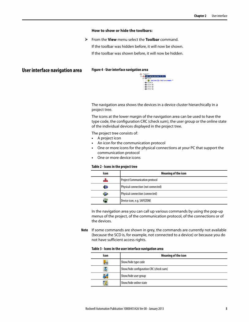
User interface navigation area Figure 4 - User interface navigation area
The navigation area shows the devices in a device cluster hierarchically in a project tree.
The icons at the lower margin of the navigation area can be used to have the type code, the configuration CRC (check sum), the user group or the online state of the individual devices displayed in the project tree.
The project tree consists of:• A project icon• An icon for the communication protocol• One or more icons for the physical connections at your PC that support the
communication protocol• One or more device icons
Table 2 - Icons in the project tree
In the navigation area you can call up various commands by using the pop-up menus of the project, of the communication protocol, of the connections or of the devices.
Note If some commands are shown in grey, the commands are currently not available (because the SCD is, for example, not connected to a device) or because you do not have sufficient access rights.
Table 3 - Icons in the user interface navigation area
Icon Meaning of the icon
Project/Communication protocol
Physical connection (not connected)
Physical connection (connected)
Device icon, e.g. SAFEZONE
Icon Meaning of the icon
Show/hide type code
Show/hide configuration CRC (check sum)
Show/hide user group
Show/hide online state
6 Rockwell Automation Publication 10000455426 Ver 00 - January 2013
Chapter 2 User interface
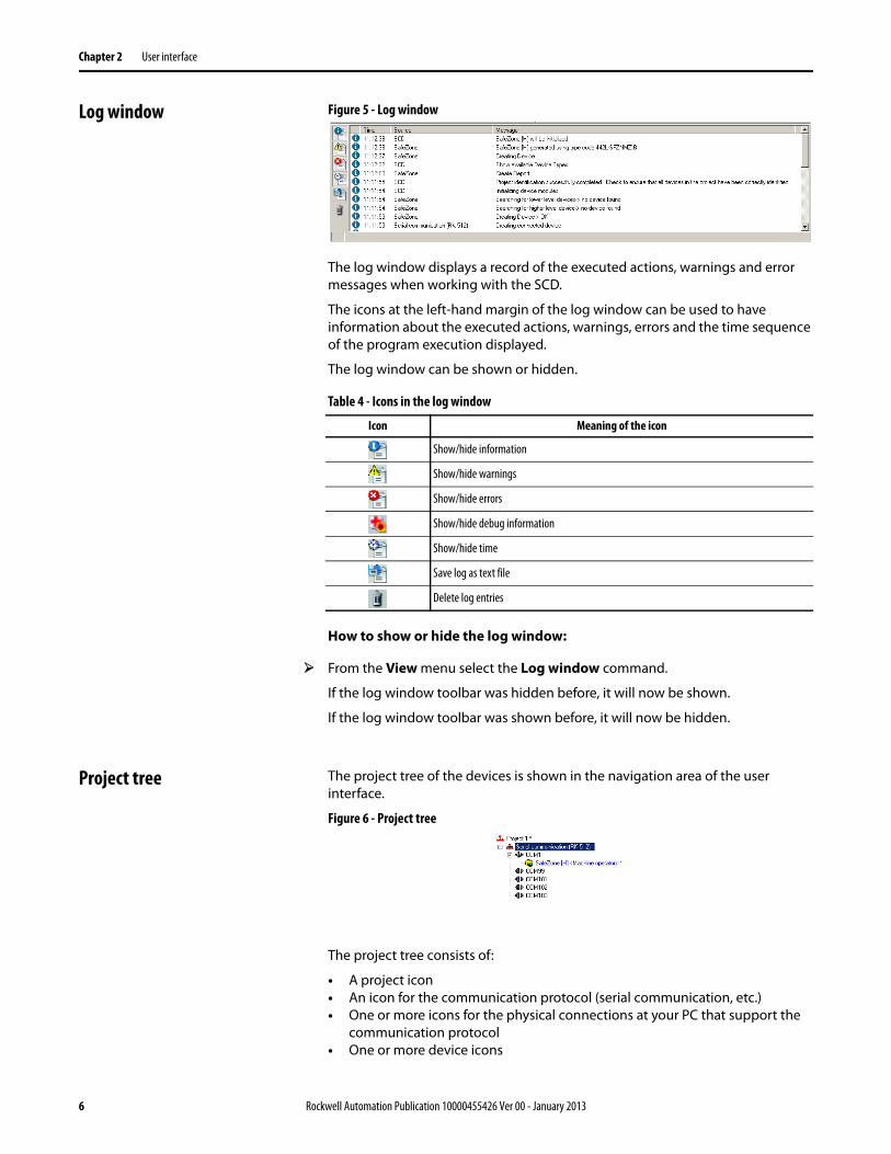
Log window Figure 5 - Log window
The log window displays a record of the executed actions, warnings and error messages when working with the SCD.
The icons at the left-hand margin of the log window can be used to have information about the executed actions, warnings, errors and the time sequence of the program execution displayed.
The log window can be shown or hidden.
Table 4 - Icons in the log window
How to show or hide the log window:
From the View menu select the Log window command.
If the log window toolbar was hidden before, it will now be shown.
If the log window toolbar was shown before, it will now be hidden.
Project tree The project tree of the devices is shown in the navigation area of the user interface.
Figure 6 - Project tree
The project tree consists of:
• A project icon• An icon for the communication protocol (serial communication, etc.)• One or more icons for the physical connections at your PC that support the
communication protocol• One or more device icons
Icon Meaning of the icon
Show/hide information
Show/hide warnings
Show/hide errors
Show/hide debug information
Show/hide time
Save log as text file
Delete log entries

Rockwell Automation Publication 10000455426 Ver 00 - January 2013 7
Chapter 2 User interface
Table 5 - Icons in the project tree
The devices existing in the project tree can be displayed as “active” or “passive”:
Table 6 - Icons in the project tree
The status of the devices is indicated by the color of the label:
Table 7 - Font colors in the project tree
Icon Meaning of the icon
Project/Communication protocol
Physical connection (not connected)
Physical connection (connected)
Device icon, e.g. SAFEZONE
Icon examples Meaning
Active devices are shown in color. Active means that the device has a counterpart device to which a connection could be established via the interface and that it has been identified by the SCD.
Passive devices are displayed in grey.Passive means that there is at present no connection to this device, either because it is currently disconnected or because it could not be identified.This is important at devices such as the safety light curtain SAFESHIELD that consists of sender and receiver. Since the PC with the SCD can only be connected to a receiver or sender, the corresponding device is always displayed passively.
The device to which the PC is connected can be recognized by the device icon with the PC.
Unknown devices or devices that are not identified are indicated by a question mark.
Font color Meaning
Devices that are ready to operateYou are working in online mode. The connection to the device has been established, the device was identified and is configured.
Devices that are not configured or at which a fault has occurred.You are working in online mode. The connection to the device has been established. However, a fault has occurred or the device is not configured.Configuration or diagnostics of the device is required.
Devices at which the SCD cannot determine the state (not connected, not identified).You are working in offline mode.Configuration of the device is required.

8 Rockwell Automation Publication 10000455426 Ver 00 - January 2013
Chapter 2 User interface
Project name Figure 7 - Project name
You can change the name of a project. When the project is stored, the project name is suggested by the SCD as the file name. Use, for example, names as the project name with which you can allocate your projects to the machines or systems that are being backed up.
How to change the name of a project:
From the pop-up menu for the project, select the Change name... command.The Change project name dialog box opens.
Type a new name in the Project name field.
Click the OK button.The dialog box is closed and the new name is displayed in the project tree.

Rockwell Automation Publication 10000455426 Ver 00 - January 2013 9
Chapter 3 Device window
Chapter 3
Device window
Figure 8 - Device window (e.g. SAFEZONE)
The device window is opened with a double-click on the device icon in the navigation area of the user interface. You can configure and diagnose the device in the device window.
The device window consists of:
• Title bar (1)• Menu bar (2)• Device information area (3)• Toolbar (4)• Navigation area (5)• Working area (6)• Status bar (7)
The size ratio of the navigation and working windows can be changed.
The toolbar, the status bar, the device information area and the navigation area can be shown and hidden.
Device window menu bar Figure 9 - Device window menu bar
The menu bar contains the commands for the fundamental operation of the device windows and for editing the configuration data. Any further menus with device-specific commands are displayed in the menu bar.
10 Rockwell Automation Publication 10000455426 Ver 00 - January 2013
Chapter 3 Device window
Notes • Menus/commands that are shown in grey are currently not available (because the SCD is, for example, not connected to a device) or because you do not have sufficient access rights.
• The explanation of the device-specific menus/commands can be found in the device-specific online help. This can be called up by using the table of contents of the online help (Contents button).
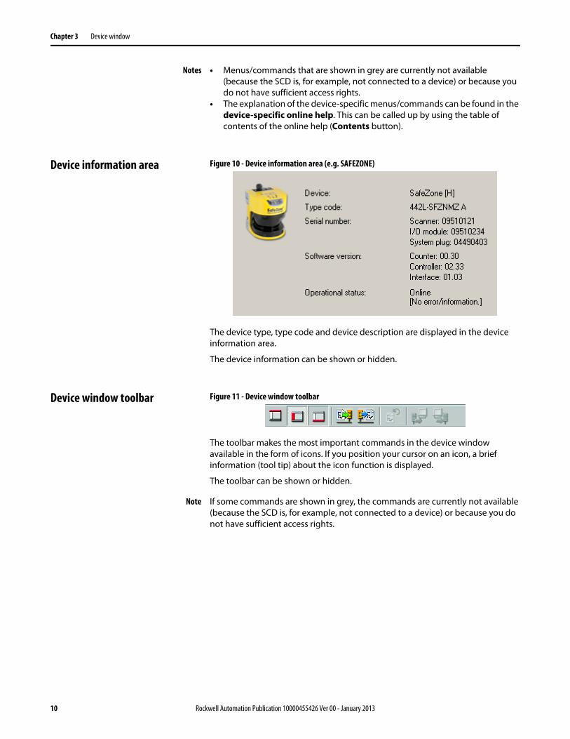
Device information area Figure 10 - Device information area (e.g. SAFEZONE)
The device type, type code and device description are displayed in the device information area.
The device information can be shown or hidden.
Device window toolbar Figure 11 - Device window toolbar
The toolbar makes the most important commands in the device window available in the form of icons. If you position your cursor on an icon, a brief information (tool tip) about the icon function is displayed.
The toolbar can be shown or hidden.
Note If some commands are shown in grey, the commands are currently not available (because the SCD is, for example, not connected to a device) or because you do not have sufficient access rights.

Rockwell Automation Publication 10000455426 Ver 00 - January 2013 11
Chapter 3 Device window
Table 8 - Icons in the device window toolbar
Device window navigation area Figure 12 - Device window navigation area
The following elements are displayed in a tree structure in the navigation area:
• Devices/device cluster• Functions of the SCD (depending on the device class configuration,
diagnostics, service and further device-specific functions)• Tab cards with the configurable functions and parameters• Properties
Note The view in the navigation area is device-specific. Further information about the device window can be found in the device-specific online helps. This can be called up by using the table of contents of the online help (Contents button).
Icon Meaning of the icon
Show/hide device information
Show/hide tree view
Show/hide status bar
Undo changes to the configuration
Import device configuration
Export device configuration
Transfer configuration
Receive configuration
Page tab cards forwards
Page tab cards backwards
Call up context-sensitive help
12 Rockwell Automation Publication 10000455426 Ver 00 - January 2013
Chapter 3 Device window
Table 9 - Icons in the device window navigation area
The navigation area with the tree structure can be shown and hidden.
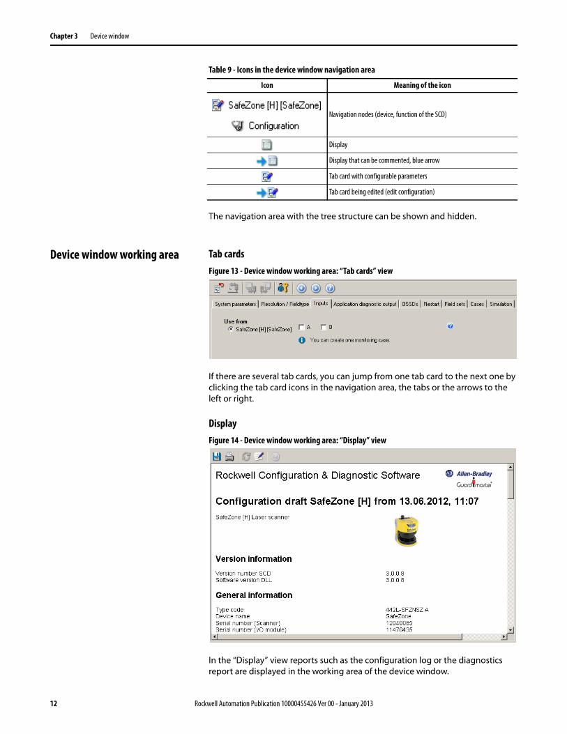
Device window working area Tab cardsFigure 13 - Device window working area: “Tab cards” view
If there are several tab cards, you can jump from one tab card to the next one by clicking the tab card icons in the navigation area, the tabs or the arrows to the left or right.
DisplayFigure 14 - Device window working area: “Display” view
In the “Display” view reports such as the configuration log or the diagnostics report are displayed in the working area of the device window.
Icon Meaning of the icon
Navigation nodes (device, function of the SCD)
Display
Display that can be commented, blue arrow
Tab card with configurable parameters
Tab card being edited (edit configuration)
Rockwell Automation Publication 10000455426 Ver 00 - January 2013 13
Chapter 3 Device window
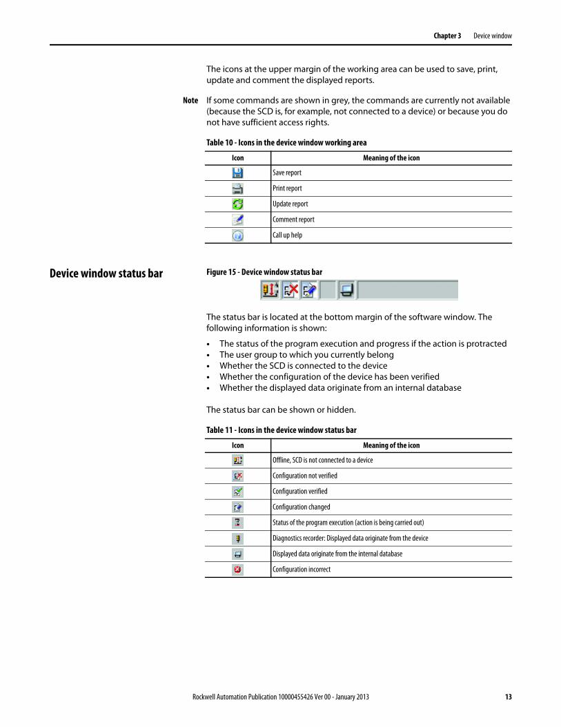
The icons at the upper margin of the working area can be used to save, print, update and comment the displayed reports.
Note If some commands are shown in grey, the commands are currently not available (because the SCD is, for example, not connected to a device) or because you do not have sufficient access rights.
Table 10 - Icons in the device window working area
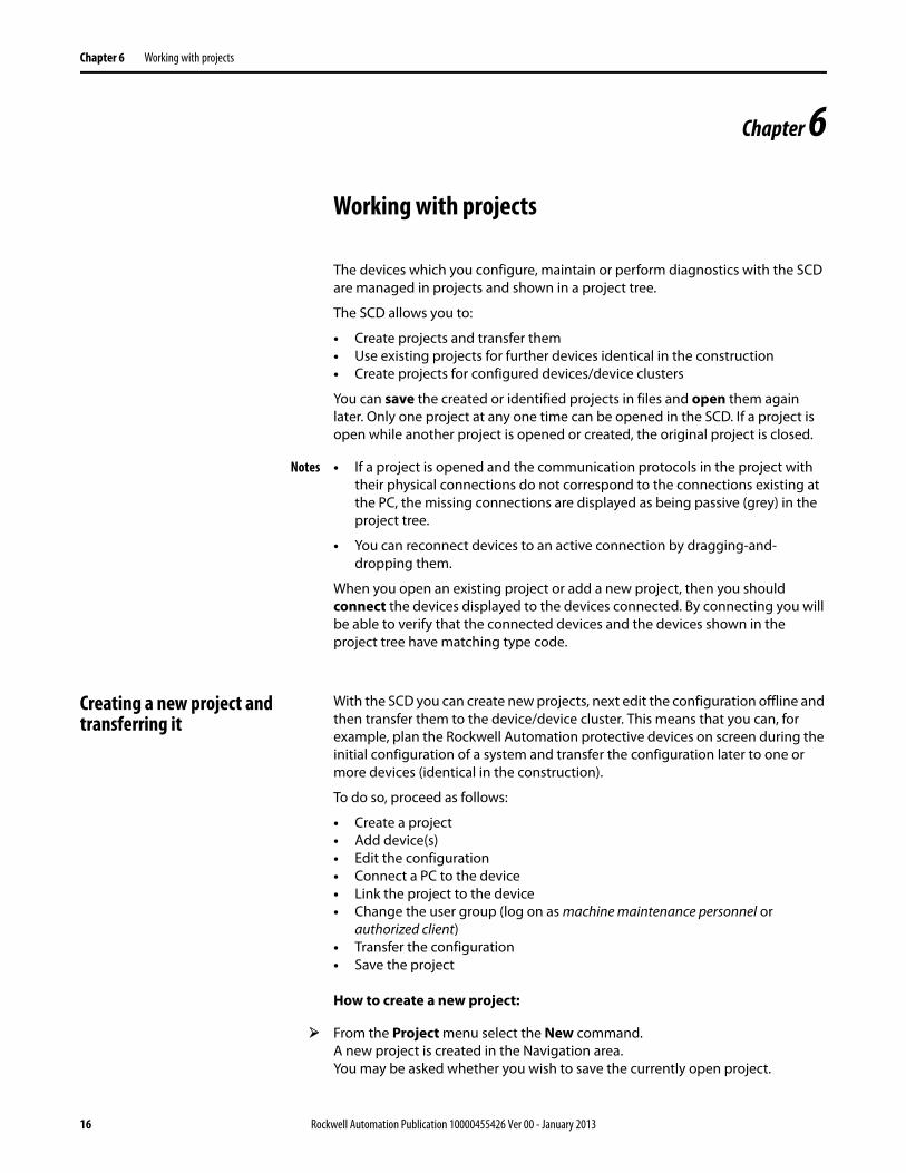
Device window status bar Figure 15 - Device window status bar
The status bar is located at the bottom margin of the software window. The following information is shown:
• The status of the program execution and progress if the action is protracted• The user group to which you currently belong• Whether the SCD is connected to the device• Whether the configuration of the device has been verified• Whether the displayed data originate from an internal database
The status bar can be shown or hidden.
Table 11 - Icons in the device window status bar
Icon Meaning of the icon
Save report
Print report
Update report
Comment report
Call up help
Icon Meaning of the icon
Offline, SCD is not connected to a device
Configuration not verified
Configuration verified
Configuration changed
Status of the program execution (action is being carried out)
Diagnostics recorder: Displayed data originate from the device
Displayed data originate from the internal database
Configuration incorrect

14 Rockwell Automation Publication 10000455426 Ver 00 - January 2013
Chapter 4 Printer setup
Chapter 4
Printer setup
You can print the diagnostics reports and the configuration logs as hard copies. To this purpose a printer has to be selected and set up for the SCD.
How to set up a printer for the SCD:
From the Project menu select the Printer setup... command.The usual operating system dialog box for selecting and setting up the printer is opened.

Rockwell Automation Publication 10000455426 Ver 00 - January 2013 15
Chapter 5 Validating products
Chapter 5
Validating products
For some devices you can validate additional functions in the SCD that have to be licensed.
How to validate products in the SCD:
From the Extras menu select the Validate products… command.The Validate products dialog box is opened.
Select the product that you want to validate in the Product field.
Enter the validation code in the Validation code field.
Click the Validate button.The product is validated.
16 Rockwell Automation Publication 10000455426 Ver 00 - January 2013
Chapter 6 Working with projects
Chapter 6
Working with projects
The devices which you configure, maintain or perform diagnostics with the SCD are managed in projects and shown in a project tree.
The SCD allows you to:
• Create projects and transfer them• Use existing projects for further devices identical in the construction• Create projects for configured devices/device clusters
You can save the created or identified projects in files and open them again later. Only one project at any one time can be opened in the SCD. If a project is open while another project is opened or created, the original project is closed.
Notes • If a project is opened and the communication protocols in the project with their physical connections do not correspond to the connections existing at the PC, the missing connections are displayed as being passive (grey) in the project tree.
• You can reconnect devices to an active connection by dragging-and-dropping them.
When you open an existing project or add a new project, then you should connect the devices displayed to the devices connected. By connecting you will be able to verify that the connected devices and the devices shown in the project tree have matching type code.
Creating a new project and transferring it
With the SCD you can create new projects, next edit the configuration offline and then transfer them to the device/device cluster. This means that you can, for example, plan the Rockwell Automation protective devices on screen during the initial configuration of a system and transfer the configuration later to one or more devices (identical in the construction).
To do so, proceed as follows:
• Create a project• Add device(s)• Edit the configuration• Connect a PC to the device• Link the project to the device• Change the user group (log on as machine maintenance personnel or
authorized client)• Transfer the configuration• Save the project
How to create a new project:
From the Project menu select the New command.A new project is created in the Navigation area.You may be asked whether you wish to save the currently open project.
Rockwell Automation Publication 10000455426 Ver 00 - January 2013 17
Chapter 6 Working with projects
How to connect the PC to a device from Rockwell (e.g. RK512 serial):
Connect the 9-pin Sub D plug of the connecting cable to a serial interface of your PC.
Remove the protective cap on the configuration socket of the device supplied by Rockwell.
Connect the M8 x 4 plug to the configuration socket of the device and/or the device cluster.
Notes • Ensure that the configuration line does not pass directly next to strong electrical drives or along power cables. This avoids an EMC influence on the configuration cable.
• In the case of devices that consist of senders and receivers, first connect the receiver because it has to be configured first.
How to link a project to the connected devices:
Note The SCD establishes a connection to all the connected devices below the level (project, communication protocol, physical connection) that is selected in the project tree.
From the Project menu select the Connect command.The SCD makes the connection to the connected devices and shows the corresponding device symbols in the project tree in the active mode.
How to transfer the configuration to the devices:
Notes • You can transfer the configuration to the respective device/device cluster that is selected in the project tree.
• You can only transfer the configuration if you are logged in at a device or device cluster with machine maintenance personnel or authorized client rights.
Use the right mouse button to open the pop-up menu of a device or system.
Select the command Configuration draft, Transfer.The configuration is transferred to the devices.
Note You are informed by a dialog box message that the configuration log is relevant for safety.
Click the OK button.The configuration data are displayed as a configuration log.
Check this log carefully and confirm that it is correct.
How to save a project:
From the Project menu select the Save command.The changed project data are saved.
Or, if you have not yet saved the project:
From the Project menu select the Save command.A Windows directory dialog box is opened.

18 Rockwell Automation Publication 10000455426 Ver 00 - January 2013
Chapter 6 Working with projects
Select the folder in which you want to save the project.
Enter a name for the project.
Click the Save button.The project is now saved under the specified name and in the selected folder.
How to save a project under another name or in another folder:
From the Project menu select the Save as... command.A Windows directory dialog box is opened.
Select the folder in which you want to save the project.
Enter a name for the project.
Click the Save button.The project is now saved under the specified name and in the selected folder.
Using an existing project for further devices
With the SCD you can open existing projects and transfer the configuration to devices of the same type (with the same type code) and with the same design use.
To do so, proceed as follows:
• Connect a PC to the device• Open the project• Link the project to the device• Change the user group (log on as machine maintenance personnel or
authorized client)• Transfer the configuration
How to connect the PC to a device from Rockwell (e.g. RK512 serial):
Connect the 9-pin Sub D plug of the connecting cable to a serial interface of your PC.
Remove the protective cap on the configuration socket of the device supplied by Rockwell.
Connect the M8 x 4 plug to the configuration socket of the device and/or the device cluster.
Notes • Ensure that the configuration line does not pass directly next to strong electrical drives or along power cables. This avoids an EMC influence on the configuration cable.
• In the case of devices that consist of senders and receivers, first connect the receiver because it has to be configured first.
How to open a project:
From the Project menu select the Open... command.A Windows file selection dialog box is opened.You may be asked whether you wish to save the currently open project.
Rockwell Automation Publication 10000455426 Ver 00 - January 2013 19
Chapter 6 Working with projects
Select the project file to be opened.The project is shown in the SCD as a project tree; the name of the opened file is shown in the title bar.
How to link a project to the connected devices:
Note The SCD establishes a connection to all the connected devices below the level (project, communication protocol, physical connection) that is selected in the project tree.
From the Project menu select the Connect command.The SCD makes the connection to the connected devices and shows the corresponding device symbols in the project tree in the active mode.
How to transfer the configuration to the devices:
• You can transfer the configuration to the respective device/device cluster that is selected in the project tree.
• You can only transfer the configuration if you are logged in at a device or device cluster with machine maintenance personnel or authorized client rights.
Use the right mouse button to open the pop-up menu of a device or system.
There select the command Configuration draft, Transfer.The configuration is transferred to the devices.
Note You are informed by a dialog box message that the configuration log is relevant for safety.
Click the OK button.The configuration data are displayed as a configuration log.
Check this log carefully and confirm that it is correct.
Creating a project for already configured devices
You can have devices that are already cabled and configured identified by the SCD, receive the existing configuration of the devices, edit them and transfer them back to the devices. By this method a new project that you can save is created in the SCD.
To do so, proceed as follows:
• Connect a PC to the device• Receive the configuration • Change the user group (log on as machine maintenance personnel or
authorised client)• Edit the configuration• Transfer the configuration• Save the project
Note During project identification, the software only identifies the type of connected devices and identifies these. To ensure that you receive the configuration of the connected devices in the SCD, the software will prompt you to receive the current device configuration. This is important as otherwise the SCD displays an “empty” configuration draft, and not the configuration draft that was transferred to the device connected during earlier configuration.

20 Rockwell Automation Publication 10000455426 Ver 00 - January 2013
Chapter 6 Working with projects
How to connect the PC to a device from Rockwell (e.g. RK512 serial):
Connect the 9-pin Sub D plug of the connecting cable to a serial interface of your PC.
Remove the protective cap on the configuration socket of the device supplied by Rockwell.
Connect the M8 x 4 plug to the configuration socket of the device and/or the device cluster.
Notes • In order to avoid an EMC influence on the configuration cable, ensure that the configuration line does not pass directly next to strong electrical drives or along power cables.
• In the case of devices that consist of senders and receivers, first connect the receiver because it has to be configured first.
How to identify the connected devices:
Connect the PC to one of the devices.
Note The SCD identifies all the devices below the level (project, communication protocol, physical connection) that is selected in the project tree.
From the Project menu select the Identify command.The SCD creates a blank project, establishes the connection with the connected devices, identifies these, and shows them as a project tree with device icons. The program status is displayed in the log window during this time.Once the devices have been identified, you are asked via a message dialog box whether you would like to receive the current device configuration in the SCD.
Click the Yes button.The device configuration is received. You are informed of this in a dialog box.
Click the OK button.A dialog box is displayed that prompts you to check the identified devices.
Note Faulty cable connections can cause device constellations to be only partially identified.
Ensure that all devices in the project have been correctly identified.
Compare the connected devices with the device information in the device window of the SCD.
Then click the OK button.
How to receive the configuration from the devices:
Note You can receive the configuration from the respective device/device cluster that is selected in the project tree.
Use the right mouse button to open the pop-up menu of a device or system.
Here select the command Configuration draft, Receive.The current configuration of all connected devices is read in and can be subsequently edited within the SCD
Rockwell Automation Publication 10000455426 Ver 00 - January 2013 21
Chapter 6 Working with projects
How to transfer the configuration to the devices:
Notes • You can transfer the configuration to the respective device/device cluster that is selected in the project tree.
• You can only transfer the configuration if you are logged in at a device or device cluster with machine maintenance personnel or authorized client rights.
Use the right mouse button to open the pop-up menu of a device or system.
There select the command Configuration draft, Transfer.The configuration is transferred to the devices.
Note You are informed by a dialog box message that the configuration log is relevant for safety.
Click the OK button.The configuration data are displayed as a configuration log.
Check this log carefully and confirm that it is correct.
How to save a project:
From the Project menu select the Save command.The changed project data are saved.
Or, if you have not yet saved the project:
From the Project menu select the Save command.A Windows directory dialog box is opened.
Select the folder in which you want to save the project.
Enter a name for the project.
Click the Save button.The project is now saved under the specified name and in the selected folder.
How to save a project under another name or in another folder:
From the Project menu select the Save as... command.A Windows directory dialog box is opened.
Select the folder in which you want to save the project.
Enter a name for the project.
Click the Save button.The project is now saved under the specified name and in the selected folder.
Adding a device If you have created your own project in the SCD, you can also add one or several devices. The device selection wizard will assist you in this step.
22 Rockwell Automation Publication 10000455426 Ver 00 - January 2013
Chapter 6 Working with projects
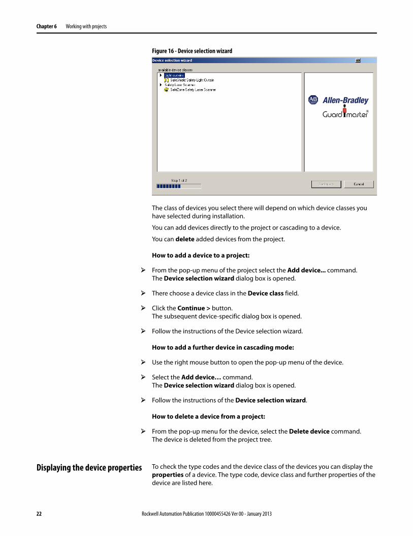
Figure 16 - Device selection wizard
The class of devices you select there will depend on which device classes you have selected during installation.
You can add devices directly to the project or cascading to a device.
You can delete added devices from the project.
How to add a device to a project:
From the pop-up menu of the project select the Add device... command.The Device selection wizard dialog box is opened.
There choose a device class in the Device class field.
Click the Continue > button.The subsequent device-specific dialog box is opened.
Follow the instructions of the Device selection wizard.
How to add a further device in cascading mode:
Use the right mouse button to open the pop-up menu of the device.
Select the Add device… command.The Device selection wizard dialog box is opened.
Follow the instructions of the Device selection wizard.
How to delete a device from a project:
From the pop-up menu for the device, select the Delete device command.The device is deleted from the project tree.
Displaying the device properties To check the type codes and the device class of the devices you can display the properties of a device. The type code, device class and further properties of the device are listed here.

Rockwell Automation Publication 10000455426 Ver 00 - January 2013 23
Chapter 6 Working with projects
How to list the properties of a device:
From the pop-up menu for the device, select the Properties command.The Device properties dialog box is opened.Here all data on the device that are related to the type code is listed.

24 Rockwell Automation Publication 10000455426 Ver 00 - January 2013
Chapter 7 Configuring a device/device cluster
Chapter 7
Configuring a device/device cluster
The configuration of the devices is password-protected, with the effect that only the members of the appropriate user groups will be able to transfer configurations to the devices.
Therefore change to the Machine operator user group if you leave the PC that is connected to the devices unattended.
Proceed as follows when configuring a device or device cluster:
Edit the configuration draft and transfer it to the connected devices.After the configuration draft has been transferred, a configuration log is displayed that you must first approve it before the configuration is enabled on the devices.
Approve the configuration log.The configuration draft is verified and is enabled on the devices.
Note You can transfer the configuration draft to devices or a system configuration only if your PC is connected to the devices and if you are registered as user in the appropriate user group of the devices.
Importing/Exporting a configuration draftThe configuration draft of a single device can also be exported and imported to other projects with devices with the same type code.
Displaying the configuration draftIf you click on Display in the navigation area of the device window, the configuration draft is displayed.
Verified configuration draftAs soon as a configuration draft has been sent and approved by an authorized client, it is deemed to be verified.
The following icons indicate whether the configuration draft is verified or not:
Table 12 - Configuration verification icons
Note After a project with a verified configuration draft has been opened, the green plus sign in the status bar is not displayed until the SCD is connected with the respective device.
Icon Meaning of the icon
Configuration not verified
Configuration verified

Rockwell Automation Publication 10000455426 Ver 00 - January 2013 25
Chapter 7 Configuring a device/device cluster
If the opened configuration draft is changed, a red cross is displayed in the status bar. The configuration draft can no longer be transferred by a machine maintenance personnel user.
A project with a verified configuration draft can be saved and later be opened and sent also to other devices by a machine maintenance personnel user.
Editing a configuration draft You can configure the functions and parameters of a device or device cluster by means of the tab cards which are accessed via the device window.
A navigation bar with the existing tab cards is displayed in the navigation area of the device window. The tab cards allow you to specifically change one or several configuration parameters.
While the tab cards are being edited, you are provided with information where parameters have been changed and where invalid values have been entered by means of a marking (asterisk or exclamation mark).
Table 13 - Device configuration change indication
Note A system with several devices (for example a cascaded system) is configured in one device window with tab cards. The tab cards are then offered several times.
How to receive the configuration from the devices:
Note You can receive the configuration from the respective device/device cluster that is selected in the project tree.
Use the right mouse button to open the pop-up menu of a device or system.
Here select the command Configuration draft, Receive.The current configuration of all connected devices is read in and can be subsequently edited within the SCD.
How to edit a configuration draft:
Use the right mouse button to open the pop-up menu of a device or system.
Here select the Open device window command.The device window is opened.
Carry out the necessary settings on the first tab card.
Click the tab for the next tab card.
Carry out the necessary settings here as well.
Marking Meaning of the marking
If values are changed on a tab card, both the device as well as the tab card in the navigation bar and the input field on the tab card are marked by an asterisk.
If invalid values are entered on a tab card, the tab card in the navigation bar as well as the value in the input field on the tab cards are displayed in red. In addition the input field on the tab card is marked with a red exclamation mark.
26 Rockwell Automation Publication 10000455426 Ver 00 - January 2013
Chapter 7 Configuring a device/device cluster
Repeat the procedure for all the tab cards.
Check all the contents of the tab cards whether the configuration data are suitable for your application.
How to undo changes to the configuration:
Select the Undo changes to the configuration command in the Device menu.You are prompted whether you want to reject all the changes to the configuration.
Click the Yes button.All the changes to the configuration are rejected.
How to transfer the configuration to the devices:
Notes • You can transfer the configuration to the respective device/device cluster that is selected in the project tree.
• You can only transfer the configuration if you are logged in at a device or device cluster with machine maintenance personnel or authorized client rights.
Use the right mouse button to open the pop-up menu of a device or system.
There select the command Configuration draft, Transfer.The configuration is transferred to the devices.
Note You are informed by a dialog box message that the configuration log is relevant for safety.
Click the OK button.The configuration data are displayed as a configuration log.
Check this log carefully and confirm that it is correct.
How to export a configuration draft:
Use the right mouse button to open the pop-up menu of a device or system.
Here select the Open device window command.The device window is opened.
Select the Export device configuration command from the File menu in the device window.A Windows directory dialog box is opened.
Select the directory in which you wish to save the device configuration file.
Enter a name for the file.
Click the Save button.The configuration file is saved in the selected directory under the specified name.
How to import a configuration draft:
Use the right mouse button to open the pop-up menu of a device or system.
Rockwell Automation Publication 10000455426 Ver 00 - January 2013 27
Chapter 7 Configuring a device/device cluster
Here select the Open device window command.The device window is opened.
Select the Import device configuration command from the File menu in the device window.
A Windows directory dialog box is opened.
Select here the device configuration file to be imported.
Click the Open button.A message box is opened confirming that the device data have been imported.
Click the OK button.The imported device configuration has been applied as the configuration draft for the device.
Approving the configuration log After the configuration data have been transferred to one or several devices, the configuration log is displayed automatically. The actual data are read out from the device and displayed.
If the read-out data match those in the configuration draft, they are displayed in black. If the read-out data differ from those in the configuration draft, they are displayed in red. In this case the configuration log cannot be approved.
You can print and save the configuration log. You can also insert a comment via an additional dialog box. This comment is also printed and saved.
Check whether the displayed configuration data exactly match those you wish to enter and that they do not deviate from the desired result due to typographical or transfer errors.
Have the machine or system checked and approved by specialist personnel after the configuration has been transferred successfully.
Note The new configuration is not activated on the device until after it has been approved. If you reject the configuration, the device or device cluster contains an invalid configuration.
Test whether the device(s) actually monitor(s) your machine or system the way you intended.
Be sure to observe the instructions for commissioning and daily checking contained for example in the operating instructions of the respective device.
How to approve a configuration log:
Carefully check each individual item of the configuration log.
Some configuration logs of devices have several pages. In this case page to the previous/next pages by means of the buttons below the vertical scroll bar or the PgUp/PgDn button.
Carefully also check the following pages of the configuration log. The Approve button does not become active until you have paged through to the last page of the configuration log.

28 Rockwell Automation Publication 10000455426 Ver 00 - January 2013
Chapter 7 Configuring a device/device cluster
Click the Approve button.The configuration data are loaded to the device/devices and initialized with the new configuration.If this has been successful, an appropriate message is displayed.
Click the OK button.The configuration loaded to the device/devices is now active.
Test whether the device(s) actually monitor(s) your machine or system the way you intended. Only after completing this step, go to real-time operation.
How to print the configuration log:
Click in the working area of the device window on the Print icon .The Windows print dialog box now opening allows you to print the configuration log.
How to show the configuration draft for a single device:
Click in the navigation area of the device window on the Display icon .The configuration draft of the respective device is displayed in the working area of the device window.
How to save the configuration log:
Click in the working area of the device window on the Save icon .A Windows directory dialog box is opened.
Select the directory in which you want to save the configuration log.
Enter a name.
Click the Save button.
The configuration log is now saved under the specified name and in the selected directory as a text file.
Rockwell Automation Publication 10000455426 Ver 00 - January 2013 29
Chapter 8 Changing the user group
Chapter 8
Changing the user group
There are various user groups in the devices from Rockwell:• Machine operator• Machine maintenance personnel• Authorized client
These user groups have different levels of authorisation for editing and transferring configurations or for diagnosing the devices.
Note The authorizations of the user groups are device-specific. The authorizations are explained in the device-specific online help. This can be called up by using the table of contents of the online help (Contents button).
When the SCD is started, you automatically belong to the user group Machine operator.
If the devices of a project were identified by the SCD, or if the SCD is connected to the devices of a project, you can switch the user groups.
You can only transfer a configuration if you are logged in at a device or device cluster with machine maintenance personnel or authorized client rights.
Password for the user group authorized clientThe factory-set password [ABGM] has been entered for the user group authorized client.
Change the password in order to protect the configuration of the devices against access by unauthorized persons.
Change to the Machine operator user group if you leave the PC that is connected to the devices unattended.
Password at devices in a device clusterIf a device cluster has been assembled using devices that have already been configured, the individual devices may have different passwords.
In this case you will be asked for your password separately for each device.
How to switch the user group:
Note You can change the user group for the respective device/device cluster that is selected in the project tree.
From the Extras menu select the Change user group... command.The Change user group dialog box is opened.
In the User group field select the user group to which you want to change.
If you wish to switch to the user group machine maintenance personnel or authorized client, enter the appropriate password in the Password field.

30 Rockwell Automation Publication 10000455426 Ver 00 - January 2013
Chapter 8 Changing the user group
Click the Log on button.The dialog box is closed, the user group is authenticated and the new user group is displayed in the status bar.
If the password was incorrect or some devices in a device cluster have a different password: The Device: enter password dialog box is opened so that you can enter the correct password.

Rockwell Automation Publication 10000455426 Ver 00 - January 2013 31
Chapter 9 Changing the password
Chapter 9
Changing the password
The user group authorized client can enter/change the passwords for the user groups machine maintenance personnel and authorized client. The passwords are saved in the devices. This allows the devices to be protected from being configured by unauthorized persons.
How to change the password:
Using the right mouse button, open the pop-up menu of the device.
Select the command Access rights, change password... (this command is active only for the user group authorized client).The Change project password dialog box opens.
Select under Change password for if you wish to change the password for the user group machine maintenance personnel or for the user group authorized client.
Enter the new password once each in both fields under New password.
Click the OK button.The SCD loads the new password to the devices.
If you have made a typing error when entering the new password: A message is displayed.Click OK and select the command Access rights, change password... once again.
32 Rockwell Automation Publication 10000455426 Ver 00 - January 2013
Chapter 10 Resetting the password
Chapter 10
Resetting the password
If you have forgotten the password for a device, you can reset the password. To do so, you need a so-called reset password. You will get this password once you have identified yourself in writing to the manufacturer.
To do so, use the form Faxform.pdf on the SCD-CD-ROM. You will need the serial number of the device and the number of the device counter for identification. Both numbers can be found in the Reset password dialog box.
How to reset the password:
Using the right mouse button, open the pop-up menu of the respective device.
Select the command Access rights, reset password...The Reset password dialog box is opened.
Note down the serial number and the number of the device counter and close the dialog box.
Pass these numbers on to the manufacturer and identify yourself in writing. You will receive the reset password.
Open the Reset password dialog box and enter the reset password in the Reset password field.
Click the OK button.The password of the device(s) is reset to ABGM.

Rockwell Automation Publication 10000455426 Ver 00 - January 2013 33
Chapter 11 Carrying out diagnosis
Chapter 11
Carrying out diagnosis
The SCD can be used to diagnose devices that are connected and linked to the SCD (or identified by the SCD). To this purpose the diagnostic data are loaded into the working area of the device window.
You can print and save the diagnostic data. You can also insert a comment via an additional dialog box. This comment is also printed and saved.
How to save the diagnostics report:
Click in the working area of the device window on the Save icon .A Windows directory dialog box is opened.
Select the directory in which you wish to save the diagnostics report.
Enter a name.
Click the Save button.
The diagnostics report is saved as a text file under the specified name and in the selected folder.
How to print the diagnostics report:
Click in the working area of the device window on the Print icon .The Windows print dialog box now opening allows you to print the diagnostics report.
How to show the diagnostics report for a single device:
Click in the navigation area of the device window on the Display icon (in the tree structure below the diagnostics function).The diagnostics report is shown in the working area of the device window.
34 Rockwell Automation Publication 10000455426 Ver 00 - January 2013
Chapter 12 Entering comments
Chapter 12
Entering comments
You can add comments to the reports (configuration log and diagnostics report) that are displayed in the working area of the device window. These comments are also printed out and stored with the respective report.
How to enter a comment:
Click in the working area of the device window on the Comment icon .The Comment dialog box is opened.
Enter the desired comment in the text field of the dialog box.
Click the OK button.The dialog box is closed, the comment is inserted at the end of the configuration log/diagnostics report.
Rockwell Automation Publication 10000455426 Ver 00 - January 2013 35
Chapter 13 Annex
Chapter 13
Annex
List of tables Table 1: Icons in the user interface toolbar . . . . . . . . . . . . . . . . . . . . . . . . . . . . . . . . . . . 4Table 2: Icons in the project tree . . . . . . . . . . . . . . . . . . . . . . . . . . . . . . . . . . . . . . . . . . . . . 5Table 3: Icons in the user interface navigation area . . . . . . . . . . . . . . . . . . . . . . . . . . . 5Table 4: Icons in the log window . . . . . . . . . . . . . . . . . . . . . . . . . . . . . . . . . . . . . . . . . . . . . 6Table 5: Icons in the project tree . . . . . . . . . . . . . . . . . . . . . . . . . . . . . . . . . . . . . . . . . . . . . 7Table 6: Icons in the project tree . . . . . . . . . . . . . . . . . . . . . . . . . . . . . . . . . . . . . . . . . . . . . 7Table 7: Font colors in the project tree . . . . . . . . . . . . . . . . . . . . . . . . . . . . . . . . . . . . . . . 7Table 8: Icons in the device window toolbar . . . . . . . . . . . . . . . . . . . . . . . . . . . . . . . . .11Table 9: Icons in the device window navigation area. . . . . . . . . . . . . . . . . . . . . . . . .12Table 10: Icons in the device window working area . . . . . . . . . . . . . . . . . . . . . . . . . .13Table 11: Icons in the device window status bar . . . . . . . . . . . . . . . . . . . . . . . . . . . . .13Table 12: Configuration verification icons . . . . . . . . . . . . . . . . . . . . . . . . . . . . . . . . . . .24Table 13: Device configuration change indication . . . . . . . . . . . . . . . . . . . . . . . . . . .25
List of illustrations Figure 1: User interface . . . . . . . . . . . . . . . . . . . . . . . . . . . . . . . . . . . . . . . . . . . . . . . . . . . . . . 3Figure 2: User interface menu bar . . . . . . . . . . . . . . . . . . . . . . . . . . . . . . . . . . . . . . . . . . . . 4Figure 3: User interface toolbar . . . . . . . . . . . . . . . . . . . . . . . . . . . . . . . . . . . . . . . . . . . . . . 4Figure 4: User interface navigation area . . . . . . . . . . . . . . . . . . . . . . . . . . . . . . . . . . . . . . 5Figure 5: Log window . . . . . . . . . . . . . . . . . . . . . . . . . . . . . . . . . . . . . . . . . . . . . . . . . . . . . . . 6Figure 6: Project tree . . . . . . . . . . . . . . . . . . . . . . . . . . . . . . . . . . . . . . . . . . . . . . . . . . . . . . . . 6Figure 7: Project name. . . . . . . . . . . . . . . . . . . . . . . . . . . . . . . . . . . . . . . . . . . . . . . . . . . . . . . 8Figure 8: Device window (e.g., SAFEZONE) . . . . . . . . . . . . . . . . . . . . . . . . . . . . . . . . . . . 9Figure :9 Device window menu bar . . . . . . . . . . . . . . . . . . . . . . . . . . . . . . . . . . . . . . . . . . 9Figure 10: Device information area (e.g., SAFETZONE) . . . . . . . . . . . . . . . . . . . . . . .10Figure 11: Device window toolbar . . . . . . . . . . . . . . . . . . . . . . . . . . . . . . . . . . . . . . . . . .10Figure 12: Device window navigation area . . . . . . . . . . . . . . . . . . . . . . . . . . . . . . . . . .11Figure 13: Device window working area: “Tab cards” view . . . . . . . . . . . . . . . . . . .12Figure 14: Device window working area: “Display” view. . . . . . . . . . . . . . . . . . . . . .12Figure 15: Device window status bar . . . . . . . . . . . . . . . . . . . . . . . . . . . . . . . . . . . . . . . .13Figure 16: Device selection wizard . . . . . . . . . . . . . . . . . . . . . . . . . . . . . . . . . . . . . . . . . .22

36 Rockwell Automation Publication 10000455426 Ver 00 - January 2013
Chapter 13 Annex

xx

www.rockwellautomation.com
Power, Control and Information Solutions HeadquartersAmericas: Rockwell Automation, 1201 South Second Street, Milwaukee, WI 53204 USA, Tel: (1) 414.382.2000, Fax: (1) 414.382.4444Europe/Middle East/Africa: Rockwell Automation, Vorstlaan/Boulevard du Souverain 36, 1170 Brussels, Belgium, Tel: (32) 2 663 0600, Fax (32) 2 663 0640Asia Pacific: Rockwell Automation, Level 14, Core F, Cyberport 3, 100 Cyberport Road, Hong Kong, Tel: (852) 2887 4788, Fax: (852) 2508 1846
Publication 10000455426 Ver 00January 2013 Copyright 2013 Rockwell Automation, Inc. All Rights Reserved. Printed in USA.