safety evaluation report related to the license renewal · pdf file ·...
TRANSCRIPT

NUREG-1782
Safety Evaluation ReportRelated to the License Renewal of the Fort Calhoun Station, Unit 1
Docket No. 50-285
Omaha Public Power District
U.S. Nuclear Regulatory CommissionOffice of Nuclear Reactor RegulationWashington, DC 20555-0001

NUREG-1782
Safety Evaluation ReportRelated to the License Renewal ofthe Fort Calhoun Station, Unit 1
Docket No. 50-285
Omaha Public Power District
Manuscript Completed: September 2003Date Published: October 2003
Division of Regulatory Improvement ProgramsOffice of Nuclear Reactor RegulationU.S. Nuclear Regulatory CommissionWashington, DC 20555-0001
Safety Evaluation ReportRelated to the License Renewal of the Fort CalhounStation, Unit 1
Docket No. 50-285
Omaha Public Power District
U.S. Nuclear Regulatory Commission
Office of Nuclear Reactor Regulation
September 2003

ii
ABSTRACT
This safety evaluation report (SER) documents the technical review of the Fort Calhoun Station,Unit No. 1 (FCS), license renewal application (LRA) by the U.S. Nuclear RegulatoryCommission (NRC) staff (staff). By letters dated January 9 and April 5, 2002, Omaha PublicPower District (OPPD or the applicant) submitted the LRA for FCS in accordance with Title 10of the Code of Federal Regulations Part 54 (10 CFR Part 54 or the Rule). OPPD is requestingrenewal of the operating license for Unit 1 (license numbers DPR-40) for a period of 20 yearsbeyond the current expiration of midnight, August 9, 2013.
The FCS site is located in Washington County, NE, on the west bank of the Missouri River,approximately 19 miles north of Omaha, NE. The construction permit was issued by NRC onJune 7, 1968, and the operating license was issued August 9, 1973. The unit consists of aCombustion Engineering (CE) pressurized-water reactor (PWR) nuclear steam supply systemdesigned to generate 1500 MW-thermal, or approximately 475 MW-electric.
This SER presents the status of the staff’s review of information submitted to the NRC throughAugust 7, 2003. In its SER issued on April 21, 2003, the staff identified open and confirmatoryitems that had to be resolved before the staff could make a final determination on theapplication. These items and their resolutions are summarized in Sections 1.5 and 1.6 of thisreport. The staff’s final conclusion of its review of the FCS LRA can be found in Section 6 ofthis SER.
iii
ABBREVIATIONS
AB-FO auxiliary boiler fuel oilac alternating currentACI American Concrete InstituteACRS Advisory Committee on Reactor SafeguardsACSR aluminum conductor, steel reinforcedAERM aging effect requiring managementAFW auxiliary feedwaterAMP aging management programAMR aging management reviewANSI American National Standards InstituteAOV air-operated valveASME American Society of Mechanical EngineersASTM American Society for Testing and MaterialsATWS anticipated transient without scramAWWA American Water Works AssociationB&W Babcock & WilcoxB&WOG Babcock & Wilcox Owners GroupBAC boric acid corrosionBL BulletinBTP branch technical positionBWR boiling-water reactorCA compressed airCAP corrective action programCASS cast austenitic stainless steelCCNPP Calvert Cliffs Nuclear Power PlantCCW component cooling waterCE Combustion Engineering; control elementCEA control element assemblyCEDM control element drive mechanismCEOG Combustion Engineering Owners GroupCFR Code of Federal RegulationsCI confirmatory itemCIAS containment isolation actuation signalCIV containment isolation valveCLB current licensing basisCMAA Crane Manufacturers Association of AmericaCQE critical quality elementCR condition reportCRD control rod driveCS containment sprayCSB core support barrelCUF cumulative usage factorCVCS chemical and volume control systemDBA design-basis accidentDBD design-basis documentDBE design-basis event

iv
ABBREVIATIONS (con’t)
dc direct currentDG diesel generatorDGFO emergency diesel generator fuel oilDGLO emergency diesel generator lube oilDSS diverse scram systemEA engineering analysisECCS emergency core cooling systemECT eddy current testingEDG emergency diesel generatorEEQ electrical equipment qualificationEFPY effective full-power yearEFWST emergency feedwater storage tankEOCI Electric Overhead Crane InstituteEPRI Electric Power Research InstituteEQ environmental qualificationESF engineered safety featureESFAS engineered safety features actuation systemFAC flow-accelerated corrosionFACTS Fort Calhoun Automatic Cable Tracking SystemFCS Fort Calhoun Station, Unit 1FHA fire hazard analysisFMP fatigue monitoring programFP fire protectionFP-FO fire protection fuel oilFPP fire protection programFPS feet per secondFSAR final safety analysis reportFW feedwaterGALL Generic Aging Lessons LearnedGE General Electric Co.GEIS generic environmental impact statementGL generic letterGWD gaseous waste disposalHELB high-energy line breakHEPA high-efficiency particulate air HPCI high-pressure coolant injectionHPSI high-pressure safety injectionHVAC heating, ventilation, and air conditioningI&C instrumentation and controlIA instrument air IASCC irradiation-assisted stress-corrosion crackingICI in-core instrumentationIEEE Institute of Electrical and Electronic EngineersIGA intergranular attackIGSCC intergranular stress-corrosion crackingIN information notice

v
ABBREVIATIONS (con’t)
IPA integrated plant assessmentISG interim staff guidanceISI inservice inspectionLBB leak before breakLER licensee event reportLOCA loss-of-coolant accidentLPSI low-pressure safety injectionLRA license renewal applicationLRDB license renewal databaseLTOP low-temperature overpressure protectionLWD liquid waste disposalMCRE main control room envelopeMFW main feedwaterMIC microbiologically influenced corrosionMo molybdenum Mn manganeseMS main steamMSIV main steam isolation valveMW megawattn/cm2 neutrons per square centimeterNDE nondestructive examinationNEI Nuclear Energy InstituteNEPA National Environmental Policy ActNFPA National Fire Protection AssociationNG nitrogen gasNi nickelNPAR nuclear plant aging researchNPS nominal pipe sizeNRC U.S. Nuclear Regulatory CommissionNSSS nuclear steam supply systemOD outside diameterODCM offsite dose calculation manualODSCC outer-diameter stress-corrosion crackingOI open itemOPPD Omaha Public Power DistrictP&ID piping and instrumentation diagramPBD program basis documentPM preventive maintenancePOI potential open itemPORV power-operated relief valveppm parts per millionPRA probability and risk assessment; probabilistic risk assessmentPS primary samplingpsia pounds per square inch, atmospheric (pressure)PS/PMP periodic surveillance and preventive maintenance program

vi
ABBREVIATIONS (con’t)
P/T pressure and temperaturePTS pressurized thermal shockPVC polyvinyl chloride PWR pressurized-water reactorPWSCC primary water stress-corrosion crackingQA quality assuranceRAI request for additional informationRAMS resource acquisition management systemRC reactor coolantRCIC reactor core isolation coolingRCP reactor coolant pumpRCPB reactor coolant pressure boundaryRCS reactor coolant systemRG regulatory guideRIS Regulatory Issue Summary RMS radiation monitoring systemRPS reactor protection systemRS reactor systemRTNDT reference temperature nil ductilityRTPTS PTS reference temperatureRTD resistance temperature detectorRV reactor vessel; relief valveRVI reactor vessel internalsRVII reactor vessel internals inspectionRVIP reactor vessel integrity programRW raw waterSBO station blackoutSC structure and componentSCC stress-corrosion crackingSDC shutdown coolingSER safety evaluation reportSFP spent fuel poolSFPC spent fuel pool coolingSG steam generatorSGIS steam generator isolation signalSGP steam generator programSI safety injectionSI&CS safety injection and containment spraySIAS safety injection actuation signalSIRWT safety injection and refueling water tankSMP structures monitoring programSO standing orderSOC Statements of ConsiderationSOER Significant Operating Experience ReportSPCS steam and power conversion systemsSRP Standard Review Plan

vii
ABBREVIATIONS (con’t)
SRP-LR Standard Review Plan - license renewalSSC structures, systems, and componentsSSEL safe shutdown equipment list SV safety valveT thicknessTLAA time-limited aging analysisTR topical reportUCS Union of Concerned ScientistsUFHA updated fire hazards analysisUGS upper guide structureUSAR updated safety analysis reportUSAS United States of America StandardsUSE upper-shelf energyUT ultrasonic testingVA ventilating airvac volt alternating currentVCT volume control tankvdc volt direct currentVHP vessel head penetration

viii
TABLE OF CONTENTS
ABSTRACT . . . . . . . . . . . . . . . . . . . . . . . . . . . . . . . . . . . . . . . . . . . . . . . . . . . . . . . . . . . . . . . ii
ABBREVIATIONS . . . . . . . . . . . . . . . . . . . . . . . . . . . . . . . . . . . . . . . . . . . . . . . . . . . . . . . . . . iii
1 INTRODUCTION AND GENERAL DISCUSSION . . . . . . . . . . . . . . . . . . . . . . . . . . . 1-1
1.1 Introduction . . . . . . . . . . . . . . . . . . . . . . . . . . . . . . . . . . . . . . . . . . . . . . . . . . 1-11.2 License Renewal Background . . . . . . . . . . . . . . . . . . . . . . . . . . . . . . . . . . . . 1-2
1.2.1 Safety Review . . . . . . . . . . . . . . . . . . . . . . . . . . . . . . . . . . . . . . . . . . 1-31.2.2 Environmental Review . . . . . . . . . . . . . . . . . . . . . . . . . . . . . . . . . . . . 1-4
1.3 Principal Review Matters . . . . . . . . . . . . . . . . . . . . . . . . . . . . . . . . . . . . . . . . 1-51.4 Interim Staff Guidance . . . . . . . . . . . . . . . . . . . . . . . . . . . . . . . . . . . . . . . . . . 1-61.5 Summary of Open Items . . . . . . . . . . . . . . . . . . . . . . . . . . . . . . . . . . . . . . . . 1-81.6 Summary of Confirmatory Items . . . . . . . . . . . . . . . . . . . . . . . . . . . . . . . . . 1-271.7 Summary of Proposed License Conditions . . . . . . . . . . . . . . . . . . . . . . . . . 1-29
2 STRUCTURES AND COMPONENTS SUBJECT TO AN AGING MANAGEMENTREVIEW . . . . . . . . . . . . . . . . . . . . . . . . . . . . . . . . . . . . . . . . . . . . . . . . . . . . . . . . . . 2-1
2.1 Scoping and Screening Methodology . . . . . . . . . . . . . . . . . . . . . . . . . . . . . . . 2-22.2 Plant-Level Scoping Results . . . . . . . . . . . . . . . . . . . . . . . . . . . . . . . . . . . . 2-212.3 Scoping and Screening Results: Mechanical Systems . . . . . . . . . . . . . . . . . 2-26
2.3.1 Reactor Systems . . . . . . . . . . . . . . . . . . . . . . . . . . . . . . . . . . . . . . . 2-272.3.2 Engineered Safety Features Systems . . . . . . . . . . . . . . . . . . . . . . . 2-362.3.3 Auxiliary Systems . . . . . . . . . . . . . . . . . . . . . . . . . . . . . . . . . . . . . . . 2-402.3.4 Steam and Power Conversion Systems . . . . . . . . . . . . . . . . . . . . . . 2-74
2.4 Scoping and Screening Results: Structures . . . . . . . . . . . . . . . . . . . . . . . . . 2-782.4.1 Containment . . . . . . . . . . . . . . . . . . . . . . . . . . . . . . . . . . . . . . . . . . . 2-782.4.2 Other Structures . . . . . . . . . . . . . . . . . . . . . . . . . . . . . . . . . . . . . . . . 2-832.4.3 Evaluation Findings . . . . . . . . . . . . . . . . . . . . . . . . . . . . . . . . . . . . . 2-98
2.5 Scoping and Screening Results: Electrical andInstrumentation and Controls . . . . . . . . . . . . . . . . . . . . . . . . . . . . . . . . . . . . 2-99
3 AGING MANAGEMENT REVIEW . . . . . . . . . . . . . . . . . . . . . . . . . . . . . . . . . . . . . . . 3-1
3.0 Aging Management Reviews . . . . . . . . . . . . . . . . . . . . . . . . . . . . . . . . . . . . . 3-13.0.1 The GALL Format for the LRA . . . . . . . . . . . . . . . . . . . . . . . . . . . . . . 3-23.0.2 The Staff’s Review Process . . . . . . . . . . . . . . . . . . . . . . . . . . . . . . . . 3-43.0.3 Aging Management Programs . . . . . . . . . . . . . . . . . . . . . . . . . . . . . . 3-63.0.4 FCS Quality Assurance Program . . . . . . . . . . . . . . . . . . . . . . . . . . . 3-43
3.1 Reactor Systems . . . . . . . . . . . . . . . . . . . . . . . . . . . . . . . . . . . . . . . . . . . . . 3-453.2 Engineered Safety Features Systems . . . . . . . . . . . . . . . . . . . . . . . . . . . . . 3-993.3 Auxiliary Systems . . . . . . . . . . . . . . . . . . . . . . . . . . . . . . . . . . . . . . . . . . . . 3-1153.4 Steam and Power Conversion Systems . . . . . . . . . . . . . . . . . . . . . . . . . . . 3-1873.5 Containment, Structures, and Component Supports . . . . . . . . . . . . . . . . . 3-2063.6 Electrical and Instrumentation and Controls . . . . . . . . . . . . . . . . . . . . . . . . 3-242
ix
4 TIME-LIMITED AGING ANALYSES . . . . . . . . . . . . . . . . . . . . . . . . . . . . . . . . . . . . . 4-1
4.1 Identification of Time-Limited Aging Analyses . . . . . . . . . . . . . . . . . . . . . . . . 4-14.2 Reactor Vessel Neutron Embrittlement . . . . . . . . . . . . . . . . . . . . . . . . . . . . . 4-34.3 Metal Fatigue . . . . . . . . . . . . . . . . . . . . . . . . . . . . . . . . . . . . . . . . . . . . . . . . 4-114.4 Environmental Qualification . . . . . . . . . . . . . . . . . . . . . . . . . . . . . . . . . . . . . 4-174.5 Concrete Containment Tendon Pre-stress . . . . . . . . . . . . . . . . . . . . . . . . . . 4-224.6 Containment Liner Plate and Penetration Sleeve Fatigue . . . . . . . . . . . . . . 4-244.7 Other TLAAs . . . . . . . . . . . . . . . . . . . . . . . . . . . . . . . . . . . . . . . . . . . . . . . . 4-26
4.7.1 Reactor Coolant Pump Flywheel Fatigue . . . . . . . . . . . . . . . . . . . . . 4-274.7.2 Leak-Before-Break (LBB) Analysis for Resolution of USI A-2 . . . . . . 4-304.7.3 High-Energy Line Break (HELB) . . . . . . . . . . . . . . . . . . . . . . . . . . . . 4-334.7.4 Alloy 600 Weld Repair in a Temperature Nozzle in the Pressurizer Lower
Shell . . . . . . . . . . . . . . . . . . . . . . . . . . . . . . . . . . . . . . . . . . . . . . . . . 4-344.8 Evaluation Findings . . . . . . . . . . . . . . . . . . . . . . . . . . . . . . . . . . . . . . . . . . . 4-37
5 REVIEW BY THE ADVISORY COMMITTEE ON REACTOR SAFEGUARDS . . . . . . 5-1
6 CONCLUSIONS . . . . . . . . . . . . . . . . . . . . . . . . . . . . . . . . . . . . . . . . . . . . . . . . . . . . 6-1
Appendix A: COMMITMENT LISTING . . . . . . . . . . . . . . . . . . . . . . . . . . . . . . . . . . . . . . . . A-1
Appendix B: CHRONOLOGY . . . . . . . . . . . . . . . . . . . . . . . . . . . . . . . . . . . . . . . . . . . . . . . B-1
Appendix C: REQUESTS FOR ADDITIONAL INFORMATION . . . . . . . . . . . . . . . . . . . . . C-1
Appendix D: PRINCIPAL CONTRIBUTORS . . . . . . . . . . . . . . . . . . . . . . . . . . . . . . . . . . . D-1

SECTION 1
INTRODUCTION AND GENERAL INFORMATION

1-ii
Section 1 - Table of Contents
1 Introduction and General Discussion . . . . . . . . . . . . . . . . . . . . . . . . . . . . . . . . . . . . . . . . 1-11.1 Introduction . . . . . . . . . . . . . . . . . . . . . . . . . . . . . . . . . . . . . . . . . . . . . . . . . . . . 1-11.2 License Renewal Background . . . . . . . . . . . . . . . . . . . . . . . . . . . . . . . . . . . . . . 1-2
1.2.1 Safety Review . . . . . . . . . . . . . . . . . . . . . . . . . . . . . . . . . . . . . . . . . . . 1-31.2.2 Environmental Review . . . . . . . . . . . . . . . . . . . . . . . . . . . . . . . . . . . . . 1-4
1.3 Summary of Principal Review Matters . . . . . . . . . . . . . . . . . . . . . . . . . . . . . . . . 1-51.4 Interim Staff Guidance . . . . . . . . . . . . . . . . . . . . . . . . . . . . . . . . . . . . . . . . . . . . 1-61.5 Summary of Open Items . . . . . . . . . . . . . . . . . . . . . . . . . . . . . . . . . . . . . . . . . . 1-81.6 Summary of Confirmatory Items . . . . . . . . . . . . . . . . . . . . . . . . . . . . . . . . . . . 1-271.7 Summary of Proposed License Conditions . . . . . . . . . . . . . . . . . . . . . . . . . . . 1-29

1-1
1 Introduction and General Discussion
1.1 Introduction
This document is a safety evaluation report (SER) on the application for license renewal for theFort Calhoun Station, Unit 1 (FCS), as filed by the Omaha Public Power District (OPPD or theapplicant). By letters dated January 9 and April 5, 2002, OPPD submitted its application to theU.S. Nuclear Regulatory Commission (NRC or the Agency) for renewal of the FCS operatinglicense for an additional 20 years. The NRC staff (the staff) prepared this report whichsummarizes the results of its safety review of the renewal application for compliance with therequirements of Title 10, Part 54 of the Code of Federal Regulations (10 CFR Part 54),“Requirements for Renewal of Operating Licenses for Nuclear Power Plants.” The NRC licenserenewal project manager for the FCS license renewal review is William F. Burton. Mr. Burtonmay be contacted by calling 301-415-2853, or by writing to the License Renewal andEnvironmental Impacts Program, U.S. Nuclear Regulatory Commission, Washington, D.C.20555-0001.
In its January 9, 2002, submittal letter, the applicant requested renewal of the operating licenseissued under Section 104b of the Atomic Energy Act of 1954, as amended, for FCS (licensenumber DPR-40) for a period of 20 years beyond the current license expiration of midnight,August 9, 2013. The FCS site is located in Washington County, NE, on the west bank of theMissouri River, approximately 19 miles north of Omaha, NE. Construction began on Unit 1 inJune 1968, and its operating license was issued on August 9, 1973. The unit consists of aCombustion Engineering (CE) pressurized-water reactor (PWR) nuclear steam supply system(NSSS) designed to generate 1500 MW-thermal, or approximately 475 MW-electric. Detailsconcerning the plant and the site are found in the updated safety analysis report (USAR) for theunit.
The license renewal process proceeds along two tracks which consist of (1) a technical reviewof safety issues and (2) an environmental review. The requirements for these reviews arestated in NRC regulations 10 CFR Parts 54 and 51, respectively. The safety review for the FCSlicense renewal is based on the applicant’s license renewal application (LRA) and on theanswers to requests for additional information (RAIs) from the staff. In meetings and docketedcorrespondence, the applicant has also supplemented its answers to the RAIs. Unlessotherwise noted, the staff reviewed and considered information submitted through August 7,2003. The LRA and all pertinent information and materials, including the USAR mentionedabove, are available to the public for review at the NRC Public Document Room, 11555Rockville Pike, Room 1-F21, Rockville, MD, 20852-2738 (301-415-4737/800-397-4209); the W.Dale Clark Library, 215 South 15th Street, Omaha, NE 68102; and the Blair Public Library, 210South 17th Street, Blair, NE 68008-2055. Material related to the LRA is also available throughthe NRC website at www.nrc.gov
This SER summarizes the results of the staff’s safety review of the FCS LRA and delineates thescope of the technical details considered in evaluating the safety aspects of FCS’ proposedoperation for an additional 20 years beyond the term of the current operating license. The LRAwas reviewed in accordance with the NRC regulations and the guidance provided in NUREG-1800, “Standard Review Plan for Review of License Renewal Applications for Nuclear PowerPlants”, dated July 2001 (SRP-LR).

1-2
Sections 2 through 4 of the SER address the staff’s review and evaluation of license renewalissues that have been considered during the review of the application. Section 5 is reserved forthe report of the Advisory Committee on Reactor Safeguards (ACRS). The conclusions of thisreport are in Section 6 of the SER.
Appendix A of this SER is a table that identifies the applicant’s commitments associated withthe renewal of the operating license. Appendix B contains a chronology of the principalcorrespondence between the NRC and the applicant related to the review of the application. Appendix C presents an index of the staff’s RAIs and the applicant’s responses. Appendix D isa list of principal contributors to the SER.
In accordance with 10 CFR Part 51, the staff prepared a draft for comment on the plant-specificsupplement to the generic environmental impact statement (GEIS) that discusses theenvironmental considerations related to renewing the license for FCS. NUREG-1437,Supplement 12, the plant-specific draft supplement to the GEIS, was issued in January 2003. The final supplement to the GEIS was issued on August 15, 2003.
1.2 License Renewal Background
Pursuant to the Atomic Energy Act of 1954, as amended, and NRC regulations, operatinglicenses for commercial power reactors are issued for 40 years. These licenses can berenewed for up to 20 additional years. The original 40-year license term was selected on thebasis of economic and antitrust considerations-not on technical limitations. However, someindividual plant and equipment designs may have been engineered on the basis of an expected40-year service life.
In 1982, the NRC held a workshop on nuclear power plant aging in anticipation of the interest inlicense renewal. That led the NRC to establish a comprehensive program plan for nuclear plantaging research (NPAR). On the basis of the results of that research, a technical review groupconcluded that many aging phenomena are readily manageable and do not pose technicalissues that would preclude life extension for nuclear power plants. In 1986, the NRC publisheda request for comment on a policy statement that would address major policy, technical, andprocedural issues related to license renewal for nuclear power plants.
In 1991, the NRC published the license renewal rule in 10 CFR Part 54 (the Rule). The NRCparticipated in an industry sponsored demonstration program to apply the rule to a pilot plantand to develop experience to establish implementation guidance. To establish a scope ofreview for license renewal, the rule defined age-related degradation unique to license renewal. However, during the demonstration program, the NRC found that many aging mechanismsoccur and are managed during the period of initial license. In addition, the NRC found that thescope of the review did not allow sufficient credit for existing programs, particularly theimplementation of the maintenance rule, which also manages plant aging phenomena. As aresult, in 1995, the NRC amended the license renewal rule. The amended 10 CFR Part 54established a regulatory process that is simpler, more stable, and more predictable than theprevious license renewal rule. In particular, 10 CFR Part 54 was amended to focus onmanaging the adverse effects of aging rather than on identifying age-related degradationunique to license renewal. The rule changes were intended to ensure that important systems,structures, and components (SSCs) will continue to perform their intended functions in the

1-3
period of extended operation. In addition, the integrated plant assessment (IPA) process wasclarified and simplified to be consistent with the revised focus on passive, long-lived structuresand components (SCs).
In parallel with these efforts, the NRC pursued a separate rulemaking effort, 10 CFR Part 51, tofocus the scope of the review of the environmental impacts of license renewal, in fulfillment ofthe NRC’s responsibilities under the National Environmental Policy Act of 1969 (NEPA).
1.2.1 Safety Review
License renewal requirements for power reactors are based on two key principles.
(1) The regulatory process is adequate to ensure that the licensing bases of all currentlyoperating plants provide and maintain an acceptable level of safety, with the possibleexception of the detrimental effects of aging on the functionality of certain plant SSCs inthe period of extended operation, as well as a few other potential issues related tosafety during the period of extended operation.
(2) The plant-specific licensing basis must be maintained during the renewal term in thesame manner and to the same extent as during the original licensing term.
In implementing these two principles, 10 CFR 54.4 defines the scope of license renewal asthose SSCs (a) that are safety-related, (b) whose failure could affect safety-related functions,and (c) that are relied on to demonstrate compliance with the NRC’s regulations for fireprotection, environmental qualification (EQ), pressurized thermal shock (PTS), anticipatedtransients without scram (ATWS), and station blackout (SBO).
Pursuant to 10 CFR 54.21(a), an applicant for a renewed license must review all SSCs withinthe scope of the Rule to identify SCs subject to an aging management review (AMR). SCssubject to an AMR are those that perform an intended function without moving parts or withouta change in configuration or properties, and that are not subject to replacement based onqualified life or specified time period. As required by 10 CFR 54.21(a), an applicant for arenewed license must demonstrate that the effects of aging will be managed in such a way thatthe intended function or functions of those SCs will be maintained, consistent with the currentlicensing basis (CLB), for the period of extended operation. Active equipment, however, isconsidered to be adequately monitored and maintained by existing programs. In other words,the detrimental aging effects that may occur for active equipment are more readily detectableand will be identified and corrected through routine surveillance, performance indicators, andmaintenance. The surveillance and maintenance programs for active equipment, as well asother aspects of maintaining the plant design and licensing basis, are required throughout theperiod of extended operation. Section 54.21(d) requires that a supplement to the final safetyanalysis report (FSAR) contain a summary description of the programs and activities formanaging the effects of aging.
Another requirement for license renewal is the identification and updating of time-limited aginganalyses (TLAAs). During the design phase for a plant, certain assumptions are made aboutthe length of time the plant will be operated; these assumptions are then incorporated intodesign calculations for several of the plant’s SSCs. Under 10 CFR 54.21(c)(1), these

1-4
calculations must be shown to be valid for the period of extended operation or must beprojected to the end of the period of extended operation, or the applicant must demonstrate thatthe effects of aging on these SSCs will be adequately managed for the period of extendedoperation.
In 2001, the NRC developed and issued Regulatory Guide (RG) 1.188, “Standard Format andContent for Applications to Renew Nuclear Power Plant Operating Licenses.” This guideendorses an implementation guideline prepared by the Nuclear Energy Institute (NEI) as anacceptable method of implementing the license renewal rule. The NEI guideline is NEI 95-10,Revision 3, “Industry Guideline for Implementing the Requirements of 10 CFR Part 54-TheLicense Renewal Rule,” which was issued in March 2001. The NRC also prepared the SRP-LRwhich, along with the RG, was used to review this application.
The OPPD is the first license renewal applicant to fully utilize the process defined in NUREG-1801, “Generic Aging Lessons Learned (GALL) Report,” dated July 2001. The purpose ofGALL is to provide the staff with a summary of staff-approved aging management programs(AMPs) for the aging of most SCs that are subject to an AMR. If an applicant commits toimplementing these staff-approved AMPs, the time, effort, and resources used to review anapplicant’s LRA will be greatly reduced, thereby improving the efficiency and effectiveness ofthe license renewal review process. The GALL Report summarizes the aging managementevaluations, programs, and activities credited for managing aging for most of the SCs usedthroughout the industry, and serves as a reference for both applicant and staff reviewers toquickly identify those AMPs and activities that the staff has determined will provide adequateaging management during the period of extended operation.
1.2.2 Environmental Review
The environmental protection regulation, 10 CFR Part 51, was revised in December 1996, tofacilitate the environmental review for license renewal. The staff prepared a GEIS, in which itexamined the possible environmental impacts associated with renewing licenses of nuclearpower plants. For certain types of environmental impacts, the GEIS establishes genericfindings that are applicable to all nuclear power plants. These generic findings are identified asCategory 1 issues in 10 CFR Part 51, Subpart A, Appendix B. Pursuant to 10 CFR 51.53(c)(3)(i), an applicant for license renewal may incorporate these generic findingsinto its environmental report. Analyses of those environmental impacts that must be evaluatedon a plant-specific basis (Category 2 issues) must be included in the environmental report inaccordance with 10 CFR 51.53(c)(3)(ii).
In accordance with NEPA and the requirements of 10 CFR Part 51, the staff performed a plant-specific review of the environmental impacts of license renewal, including whether new andsignificant information existed that was not considered in the GEIS. As part of the NRCenvironmental scoping process, a public meeting was held on June 18, 2002, in Omaha, NE, toidentify environmental issues specific to the plant. Results of the environmental review and apreliminary recommendation with respect to the license renewal action were documented inNRC’s draft plant-specific supplement to the GEIS, which was issued by the NRC on January 6,2003, and which was discussed at a separate public meeting held on February 26, 2003, inOmaha, NE. After consideration of the comments on the draft, NRC prepared NUREG-1437,

1-5
Supplement 12, “Generic Environmental Impact Statement for License Renewal of NuclearPower Plants,” which was published on August 15, 2003.
1.3 Principal Review Matters
The requirements for renewing operating licenses for nuclear power plants are described in10 CFR Part 54. The staff performed its technical review of the FCS LRA in accordance withCommission guidance and the requirements of 10 CFR Part 54. The standards for renewing alicense are contained in 10 CFR 54.29. This SER describes the results of the staff’s safetyreview.
In 10 CFR 54.19(a), the Commission requires a license renewal applicant to submit generalinformation. The applicant provided this general information in Section 1 of its LRA for FCS,submitted by letter dated January 9, 2002.
In 10 CFR 54.19(b), the Commission requires that license renewal applications include“conforming changes to the standard indemnity agreement, 10 CFR 140.92, Appendix B, toaccount for the expiration term of the proposed renewed license.” The applicant states thefollowing in its LRA regarding this issue.
The current indemnity agreement for Fort Calhoun Station, Unit 1 does not contain aspecific expiration term for the operating license. Therefore, conforming changes toaccount for the expiration term of the proposed renewed license are not necessary,unless the license number is changed upon issuance of the renewed license.
The staff intends to maintain the license type and number upon issuance of the renewedlicense. Therefore, there is no need to make conforming changes to the indemnity agreement,and the requirements of 10 CFR 54.19(b) have been met.
In 10 CFR 54.21, the Commission requires that each application for a renewed license for anuclear facility must contain (a) an IPA, (b) a description of CLB changes during staff review ofthe application, (c) an evaluation of TLAAs, and (d) an FSAR Supplement. Sections 3 and 4, aswell as Sections A and B, of the LRA address the license renewal requirements of 10 CFR 54.21(a), (c), and (d), respectively.
In 10 CFR 54.21(b), the Commission requires that each year following submittal of theapplication, and at least 3 months before the scheduled completion of the staff’s review, anamendment to the renewal application must be submitted that identifies any change to the CLBof the facility that materially affects the contents of the license renewal application, including theFSAR Supplement. This information was provided by letter dated May 16, 2003. Therefore therequirements of 10 CFR 54.21(b) have been met. In 10 CFR 54.22, the Commission lists requirements regarding technical specifications. InAppendix D of the LRA, the applicant stated that no changes to the FCS TechnicalSpecifications are necessary. This adequately addresses the requirements of 10 CFR 54.22.
The staff evaluated the technical information required by 10 CFR 54.21 and 10 CFR 54.22 inaccordance with the NRC’s regulations and the guidance provided by the SRP-LR. The staff’s

1-6
evaluation of the LRA in accordance with 10 CFR 54.21 and 10 CFR 54.22 is contained inSections 2, 3, and 4 of this report.
The staff’s evaluation of the environmental information required by 10 CFR 54.23 is included inthe draft and final plant-specific supplements to the GEIS that will state the considerationsrelated to renewing the license for FCS. When the report of the ACRS, required by 10 CFR54.25, is issued, it will be incorporated into Section 5 of this SER. The findings required by 10CFR 54.29 are included as Section 6 of this report.
1.4 Interim Staff Guidance
The license renewal program is a living program. The NRC staff, industry, and other interestedstakeholders gain experience and develop lessons learned with each renewed license. Thelessons learned address the NRC’s performance goals of maintaining safety, improvingeffectiveness and efficiency, reducing unnecessary regulatory burden, and increasing publicconfidence. The lessons learned are captured in interim staff guidance (ISG) for use by thestaff and interested stakeholders until the improved license renewal guidance documents arerevised.
The current set of relevant ISGs that have been issued by the staff, and the SER sections inwhich the issues are addressed by the staff, is provided below.
Interim Staff Guidance for License Renewal
ISG Issue(Approved ISG No.)
Purpose SER Section
Station Blackout (SBO) Scoping(ISG-02)
The license renewal rule 10 CFR 54.4(a)(3) includes 10 CFR 50.63(a)(1)-SBO. The SBO rule requires that aplant must withstand and recoverfrom an SBO event. Therecovery time for offsite power ismuch faster than that of EDGs.
The offsite power system shouldbe included within the scope oflicense renewal.
2.5.23.6.2.4.4
Concrete Aging ManagementProgram (ISG-03)
Lessons learned from the GALLDemonstration project indicatedthat GALL is not clear whetherconcrete needs any AMPs.
3.5.2.2.13.5.2.2.23.5.2.4.13.5.2.4.2

1-7
Fire Protection (FP) System Piping(ISG-04)
To clarify staff position for wallthinning of FP piping system inGALL AMPs (XI.M26 andXI.M27).
New guidance is that there is noneed to disassemble FP piping,as oxygen can be introduced inthe FP piping which canaccelerate corrosion. Instead,use nonintrusive method such asvolumetric inspection.
Testing of sprinkler heads shouldbe performed at year 50 of thesprinkler systems service life, notat year 50 of plant operations,with subsequent sprinkler headtests every 10 years thereafter.
Eliminated Halon/carbon dioxidesystem inspections for chargingpressure, valve line ups, andautomatic mode of operation testfrom GALL, as the staffconsiders these test verificationsto be operational activities.
3.0.3.9

1-8
Identification and Treatment ofElectrical Fuse Holder (ISG-05)
To include fuse holder AMR andAMP (i.e., same as terminalblocks and other electricalconnections).
The position includes only fuseholders that are not inside theenclosure of active components(e.g., inside of switchgears andinverters).
Operating experience finds thatmetallic clamps (spring-loadedclips) have a history of age-related failures from agingstressors such as vibration,thermal cycling, mechanicalstress, corrosion, and chemicalcontamination.
The staff finds that visualinspection of fuse clips is notsufficient to detect the agingeffects from fatigue, mechanicalstress, and vibration.
3.6.2.4.5
1.5 Summary of Open Items
As a result of its review of the LRA for FCS, including additional information submitted to theNRC through August 7, 2003, the staff identified the following open items. An issue was openif the applicant had not presented a sufficient basis for resolution, or if information provided tothe staff in recent applicant submittals in response to potential open items (POIs) had yet to bereviewed by the staff. Each open item was assigned a unique identifying number.
Item Description
2.2-1 During the AMR inspection and audit, the team reviewed the onsite engineeringanalysis (EA)-FC-00-149, “NSR Steam and Water Systems Impacting SSCWithin Scope For License Renewal.” In this EA, the applicant identified pipingsystems and associated reference drawings for those systems that have met the10 CFR 54.4(a)(2) criteria for spatial interaction. However, after discussionswith the staff, the applicant indicated that some of these systems are alreadyidentified as being within the scope of license renewal but were not identified asbeing within scope in the LRA. The applicant also stated that the Flow-Accelerated Corrosion (FAC), Chemistry, General Corrosion of ExternalSurfaces, and Structures Monitoring Programs are the applicable AMPs tomanage aging effects for components in these systems.
1-9
On the basis of its review, the staff determined that the information, as providedby the applicant, was not sufficient for the staff’s scoping and AMRs for these 10CFR 54.4(a)(2) SSCs. For the additional SSCs that had been brought into scopeto meet the 10 CFR 54.4(a)(2) criterion, the applicant was requested to providescoping information to the component level equivalent to that of the original LRA.This information was necessary for the staff to be able to determine that all thecomponents required by 10 CFR 54.4(a)(2) to be within the scope of licenserenewal and subject to an AMR had been correctly identified. Also, the applicantwas requested to provide revised and/or new Section 2 tables, including links toSection 3 tables, so that the staff could perform an AMR to determine whetherthe applicant had identified the proper aging effects for the combination of thematerials and environments, and had provided an adequate AMP for managingthe corresponding aging effects for these SSCs.
By letter dated February 20, 2003, the staff issued POI-1(a) requesting that theapplicant provide the above information. By letter dated March 14, 2003, theapplicant provided the requested information. The staff reviewed the informationand found that the applicant had adequately identified the SSCs within the scopeof license renewal as a result of meeting the 10 CFR 54.4(a)(2) scoping criterion. POI-1(a) is resolved. However, the staff still had to review the AMR results forthe additional components brought into scope and subject to an AMR todetermine whether they would be adequately managed during the period ofextended operation. This was identified as Open Item 2.2-1.
The staff has completed its review of the aging management informationprovided by the applicant and has determined that the SCs discussed above willbe adequately managed during the period of extended operation. On this basis,Open Item 2.2-1 is closed.
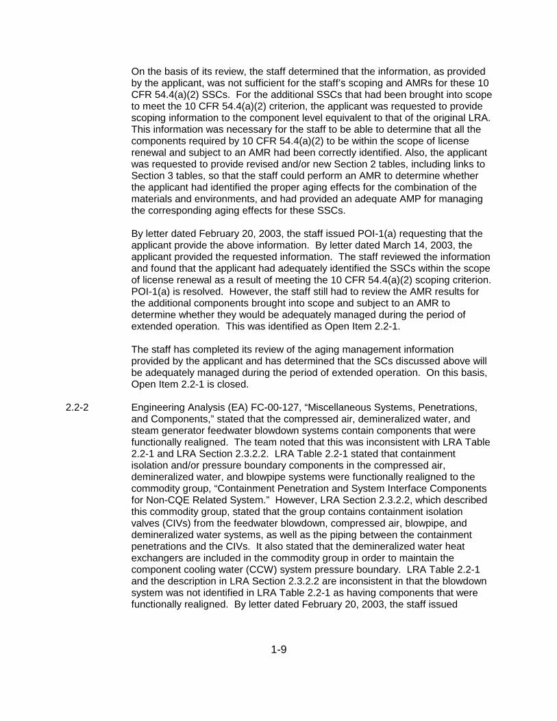
2.2-2 Engineering Analysis (EA) FC-00-127, “Miscellaneous Systems, Penetrations,and Components,” stated that the compressed air, demineralized water, andsteam generator feedwater blowdown systems contain components that werefunctionally realigned. The team noted that this was inconsistent with LRA Table2.2-1 and LRA Section 2.3.2.2. LRA Table 2.2-1 stated that containmentisolation and/or pressure boundary components in the compressed air,demineralized water, and blowpipe systems were functionally realigned to thecommodity group, “Containment Penetration and System Interface Componentsfor Non-CQE Related System.” However, LRA Section 2.3.2.2, which describedthis commodity group, stated that the group contains containment isolationvalves (CIVs) from the feedwater blowdown, compressed air, blowpipe, anddemineralized water systems, as well as the piping between the containmentpenetrations and the CIVs. It also stated that the demineralized water heatexchangers are included in the commodity group in order to maintain thecomponent cooling water (CCW) system pressure boundary. LRA Table 2.2-1and the description in LRA Section 2.3.2.2 are inconsistent in that the blowdownsystem was not identified in LRA Table 2.2-1 as having components that werefunctionally realigned. By letter dated February 20, 2003, the staff issued

1-10
POI-1(d) requesting the applicant to resolve this discrepancy between LRA Table2.2-1 and the description in LRA Section 2.3.2.2, and to provide revised Section2 tables and, if necessary, revised Section 3 tables to accurately describe whichsystems and/or components have been functionally realigned and how thecomponents will be managed.
By letter dated March 14, 2003, the applicant responded to POI-1(d), providingrevisions to LRA Table 2.2-1 and LRA Section 2.3.2.2 and an additional drawingto clearly identify the blowpipe system. On the basis of the applicant’s response,POI-1(d) was resolved. However, the staff still needed to review the informationprovided to ensure that all components within scope and subject to an AMR hadbeen identified. This was identified as Open Item 2.2-2.
The staff has now completed its review and confirmed that no components withinthese systems were omitted from scope and none that are subject to an AMRwere omitted. On the basis of the staff’s review, as described above, Open Item2.2-2 is closed.
2.3.3.15-1 Section 2.3.3.15 of the LRA stated that the raw water (RW) discharge from theCCW system heat exchangers and the discharge from the direct cooling RWheader flow into the circulating water discharge tunnel. Table 2.2-1 of the LRAdesignated the circulating water system as outside of license renewal scopewithout specific justification, but failure of the pressure boundary of buried pipingor tunnels creates the potential for a loss of RW flow. Therefore, the location ofthe license renewal boundary at the discharge pipes for the RW system, ratherthan at the outlet from the circulating water discharge tunnel, had not beenadequately justified. By letter dated February 20, 2003, the staff issued POI-3(a)requesting the applicant to justify the location of the license renewal boundary.
By letter dated March 14, 2003, the applicant responded to this POI stating thatthe location for the RW discharge license renewal boundary at check valves CW-188 and CW-189, upstream of the circulating water discharge tunnel, had beenrevised. The applicant included the circulating water discharge tunnel within thescope of license renewal as part of the intake structure. The applicantreferenced a separate letter dated March 14, 2003, which included revisedboundary drawing 11405-M-100 and new boundary drawing 11405-M-257, Sh. 2,as attachments. These drawings showed that a continuous flow path from theRW system to the river outfall had been included within scope for licenserenewal. This resolves the scoping issues associated with POI-3(a), but theexpansion of scope introduced the need for evaluation of the applicant’s AMR forthe discharge tunnel.
In its POI response, the applicant provided the following discussion regarding theAMR of the discharge tunnel.
1. The circulating water discharge tunnel is constructed of reinforced concrete with a
nominal wall thickness of 2’ or greater and nominal floor/ceiling thicknesses of 2’-6"or greater throughout. The concrete circulating water discharge tunnel walls, floorand ceiling are constructed of Type B concrete in accordance with ACI 201.2R asspecified in NUREG-1557.

1-11
2. The concrete is not exposed to aggressive river water or groundwater. Theconcrete that surrounds the embedded steel has a pH greater than or equal to 12.5.The concrete mix design specified a water-to-cement ratio of 0.44 and airentrainment of 5.00% + 1.00% for Class B concrete. The concrete at FCS wasdesigned in accordance with ACI 318-63 (per USAR Section 5.3.1 Revision 0 andUSAR Section 5.11.3.1 Revision 2).
3. The maximum flow rate in the circulating water tunnel is well below the velocity of25 fps required to initiate abrasion. The calculated highest water velocity for aclosed conduit is in the warm water recirculating tunnel at 12.6 fps. Therefore, thisaging effect is not credible.
4. Per NUREG-1557, corrosion of embedded steel is not significant for concretestructures above or below grade that are exposed to a non-aggressive environment.A non-aggressive environment, as defined by NUREG-1557, is one with a pHgreater than 11.5 or chlorides less than 500 ppm. NUREG-1557 also concludesthat corrosion of embedded steel is not significant for concrete structures exposedto an aggressive environment but have a low water-to-cement ratio, adequate airentrainment, and designed in accordance with ACI 318-63 or ACI 349-85. A lowwater-to-cement ratio is defined as 0.35 to 0.45 and adequate air entrainment isdefined as 3 to 6 percent. Therefore, corrosion of embedded steel is not credible.
5. The freeze/thaw exposure category is “Severe” since the concrete of concern is indirect contact with the soil. Based on recent analyses, the groundwater and riverwater contain minimal amounts of chlorides (8.0 ppm and 14.0 ppm respectively),sulfates (79 ppm and 229 ppm respectively), and the pH is slightly alkaline (7.48and 8.39 respectively); therefore, the exposure category for sulfates, chlorides, andacids is “Mild”, and concrete degradation is not credible for the circulating waterdischarge tunnel.
6. The total flow of the raw water equates to less than 5% of the total volume of thecirculating water discharge tunnel.
Based on the installation conditions enumerated above, the conditions specifiedin NUREG-1557 have been satisfied; therefore, minimal or no aging effects willbe realized in the circulating water discharge tunnel. Tunnel failure will not resultin a loss of the raw water intended function during the period of extendedoperation. To verify this assumption, the applicant committed to performing aone-time inspection of the circulating water discharge tunnel as part of the one-time inspection program (B.3.5).
The staff evaluated the information provided in response to POI-3(a) and foundthat the applicant had brought the circulating water discharge tunnel withinscope. Therefore, POI-3(a) was resolved. However, the staff still had to reviewthe aging management results associated with the expanded scope. This wasidentified as Open Item 2.3.3.15-1.
By letter dated July 7, 2003, the applicant revised the response contained in itssubmittal dated March 14, 2003. The applicant has chosen to manage aging ofthe circulating water tunnel as part of the structures monitoring program insteadof the one-time inspection program. The staff has reviewed the structuresmonitoring program to ensure that the scope of the program includes thecirculating water tunnel. LRA Section B.2.10 describes the structures monitoringprogram. The program description states that it is consistent with GALLProgram XI.S7, “RG 1.127, Inspection of Water-Control Structures Associatedwith Nuclear Power Plants.” The scope of GALL program XI.S7 includes intake

1-12
and discharge structures. Because the circulating water tunnel is a dischargestructure, it falls within the scope of XI.S7.
As stated above, the additional structural components of the circulating waterdischarge tunnel that were brought into scope were included and evaluated aspart of the intake structure. The staff confirmed that the circulating waterstructural components brought into scope were already identified in LRA Table2.4.2.3-1 for the intake structure. Therefore, the aging management results forthe intake structure are applicable to the circulating water discharge tunnel. Asdiscussed in Section 3.5.2.4.2 of this SER, the staff has concluded that theapplicant has demonstrated that the aging effects associated with thecomponents in structures outside containment (including the intake structure) willbe adequately managed so that their intended functions will continue to beperformed in accordance with the CLB for the period of extended operation. Onthis basis, the staff concludes that the components associated with thecirculating water discharge tunnel, as part of the intake structure, will also beadequately managed such that the components will continue to perform theirintended functions for the period of extended operation. Open Item 2.3.3.15-1 isclosed.
3.0-1 In its letter dated March 14, 2003, the applicant provided revisions to manytables in LRA Sections 2 and 3. In Appendix A of the referenced letter, OPPDresubmitted LRA tables incorporating changes made since the April 2002 LRArevision. The revised tables were formatted to indicate which changes weremade as a result of responses to NRC RAIs/POIs or as a result of additionalapplicant reviews of system EAs.
Subsequent to the submittal, the NRC project manager created a summarymatrix of the LRA table changes. On May 28 and 29, 2003, the NRC conducteda public meeting to discuss the FCS SER open and confirmatory items. Duringthe course of that meeting, the LRA table changes, and the bases for thechanges, were discussed with the applicable NRC reviewers. The applicantrevised the summary matrix to reflect the meeting conclusions. Appendix A ofthe applicant’s July 7, 2003, submittal, and clarifications provided by theapplicant on August 7, 2003, contain the revised summary of revisions to theFCS LRA tables matrix. The matrix columns include the line item number, thetable in which the change was made, a description of the change, the reason forthe change, whether the change was accepted at the public meeting, andclarification about the change where requested by the NRC reviewers.
The staff reviewed the revised information to determine whether the revisionsalter the staff’s conclusions as documented in the open items of the SER. As aresult of its review of the revised information, the staff concludes that therevisions provided by the applicant demonstrate that the SCs at FCS that aresubject to an AMR will be adequately managed during the period of extendedoperation, as required by 10 CFR 54.21(a)(3). Open Item 3.0-1 is closed.
3.3.2.4.1.2-1 For the regenerative heat exchanger, which is constructed of stainless steel andexposed to chemically treated borated water, LRA Table 2.3.3.1-1 cited link3.3.1.08 for aging management of cracking due to stress-corrosion cracking

1-13
(SCC), consistent with the GALL Report. This link stated that the agingmanagement will consist of the chemistry program, with the effectiveness of thechemistry program verified by inspections performed using either the one-timeinspection program, cooling water corrosion program, or periodic surveillanceand preventive maintenance program. In discussions during the AMR inspectionand audit, the applicant stated that the regenerative heat exchanger is weldedsuch that the internals are not accessible. Due to its construction, the applicantstated that the aging management of the regenerative heat exchanger wouldconsist of the chemistry program with further evaluation of cracking due to SCCprovided by inspection of the welds via the inservice inspection (ISI) program. The applicant considered this adequate aging management to support thepressure boundary intended function of the heat exchanger shell. Though thestaff agrees that this is acceptable for the external pressure boundary, the staffnotes that it would not detect degradation of the regenerative heat exchangertubes which could allow inventory to flow from the charging to the letdown side ofthe chemical and volume control system (CVCS). This would reduce theeffectiveness of the CVCS for managing reactor coolant system (RCS)chemistry, and may also reduce the ability of the system to inject borated waterduring an event. Therefore, the proposed aging management may not beadequate to ensure that this intended function of the heat exchanger ismaintained.
By letter dated February 20, 2003, the staff issued POI-10(b) and POI-10(i)requesting the applicant to describe inspections of the regenerative heatexchanger internals that would verify the absence of the identified aging effects,or to justify that degradation of the internals would not result in loss of function. By letter dated March 14, 2003, the applicant responded to POI-10(b) and POI-10(i), stating that a potential failure of the internal boundary between the twosides of the regenerative heat exchanger would not affect the inventory availablefor injection during an accident. The only function of the boundary is to providefor heat transfer during normal letdown operation. This function is not requiredduring an accident. On the basis of its review of the information in the POIresponses, the staff found that the applicant’s response did not explain how theplant can withstand the regulated events if the pressure boundary fails.
This pressure boundary function is important for at least two reasons over andabove the normal CVCS function of maintaining RCS water chemistry. The firstreason involves getting adequate boron injection during an event. The secondreason involves isolating a letdown line break, which is a containment bypassloss-of-coolant accident (LOCA) (note that the CVCS injection path is thenormally used path for the controlled cooldown during Appendix R events).
With regard to injection during an event, letdown is designed to isolate duringany event in which there is a need for injection. If the letdown heat exchangertubes leak sufficiently, there could be a continued loss of inventory via theletdown flowpath because one of the two letdown isolation valves is upstream ofthe heat exchanger, and would be bypassed. This would leave a single valve toisolate letdown and support injection.

1-14
Letdown is also designed to isolate during any breaks in the system to stopcontainment bypass. Again, if the letdown heat exchanger tubes leaksufficiently, the inboard isolation valve would be bypassed and a singletrain/single valve would be relied on to stop the containment bypass LOCA.
On the basis of this information, the staff requested that the applicant provideadditional information to demonstrate how degradation of the heat exchangerinternals will not adversely impact the injection function, or to provide informationon how the internals will be managed during the period of extended operation toensure that the injection function is maintained. This was identified as OpenItem 3.3.2.4.1.2-1.
By letter dated July 7, 2003, the applicant stated, in part, the following.
...flow through a tube leak in the regenerative heat exchanger (RHX) is not possibleduring design basis events (DBEs) because the letdown (tube) side of the RHXwould be isolated in response to the events. This isolation would occurautomatically upstream at the inboard containment isolation valve from the hot leg(TCV-202), and downstream at the outboard containment isolation valve (HCV-204). Backflow from the RCS through the RHX shell side is not possible due to thecharging header check valves to the loops (CH-283 and -284) and the spray line(CH-285). Additionally, the containment isolation valves, as well as the letdowncontrol valves (LCV-101-1 and -2), fail closed upon loss of air, loss of power, or lossof signal. The charging pumps, the RHX, and letdown are not credited in the USARChapter 14 safety analyses for plant shutdown nor are they used during a DBE (seeSection 9.2.5 of the USAR).
The staff reviewed the information in the FCS USAR and the applicant’s letterdated July 7, 2003, related to flow through the RHX tubes during design basisevents or the regulated events covered by 10 CFR Part 54. The staff alsoconsidered whether the RHX tubes should be considered a design feature thatwas inherently credited to mitigate a release in the event of a CVCS line break(e.g., the charging line or the letdown line outside containment). The staffconcludes that, due to the design of the FCS CVCS and the operation of theCVCS isolation valves, there is no credible scenario that would result in flowthrough the RHX tubes during design basis events or the regulated eventscovered by 10 CFR Part 54, and that pressure integrity of the RHX tubes is notrequired to isolate flow during a CVCS line break. Therefore, the staff concludesthat degradation of the RHX tubes will not result in the loss of component andCVCS intended functions. Open Item 3.3.2.4.1.2-1 is closed.
3.6.2.3.1.2-1 The staff reviewed the USAR Supplement for the non-EQ cable AMP and foundthat the supplement did not provide an adequate description of the revisedprogram, as required by 10 CFR 54.21(d). The applicant was requested tosubmit to the staff a revised USAR Supplement that is consistent with thedescriptions for GALL AMPs XI.E1, XI.E2, and XI.E3 to satisfy 10 CFR 54.21(d). This was identified as Open Item 3.6.2.3.1.2-1.
By letter dated July 7, 2003, the applicant submitted the following revised USARSupplement Section A.2.15 description that supersedes the Section A.2.15 in theLRA.

1-15
A.2.15 Non-EQ Cable Aging Management Program
The FCS Non-EQ Cable Aging Management Program is a new program thatprovides aging management of (1) non-environmentally qualified electrical cablesand connections exposed to an adverse localized environment caused by heat,radiation, or moisture; (2) non-environmentally qualified electrical cables used ininstrumentation circuits that are sensitive to reduction in conductor insulationresistance, and are exposed to an adverse localized environment caused by heat,radiation, or moisture; and (3) non-environmentally qualified inaccessible medium-voltage cables exposed to an adverse localized environment caused by moistureand voltage exposure.
Aging management is provided by the following actions:
1. Accessible electrical cables and connections installed in adverse localizedenvironments will be inspected prior to the period of extended operationand at least once every 10 years for cable and connector jacket surfaceanomalies, such as embrittlement, discoloration, cracking, swelling, orsurface contamination.
2. Electrical cables used in circuits with sensitive, low-level signals, such asradiation monitoring and nuclear instrumentation, are tested as part of theinstrumentation loop calibration at the normal calibration frequency.
3. In-scope medium voltage cables exposed to significant moisture andsignificant voltage will be tested prior to the period of extended operationand at least once every 10 years to provide an indication of the conditionof the conductor insulation. The test will be a state-of-the-art test at thetime the test is performed.
This program considers the technical information and guidance provided inNUREG/CR-5643, IEEE Std. P1205, SAND96-0344, EPRI TR-109619, and EPRITR-103834-P1-2.
The staff reviewed the above information and finds that the revised USARSupplement provides an adequate summary description of the revised Non-EQAging Management Program and that the program is consistent with GALLPrograms XI.E1, XI.E2, and XI.E3. Open Item 3.6.2.3.1.2-1 is closed.
3.6.2.4.3.2-1 LRA Table 2.5.20-1 stated that electrical bus bars and bus bar standoffs have noaging effects that require management. The basis for the applicant’s conclusionwas unclear to the staff. By letter dated February 20, 2003, the staff issued POI-6(b) requesting the applicant to provide information on the components’materials and environments, along with the basis for concluding that thesecomponents have no plausible aging effects. By letter dated March 14, 2003,the applicant responded to POI-6(b), stating the following.
The bus bar materials are copper and aluminum; their environment is in indoor airand outdoor air. In accordance with EPRI TR-114882, Non-Class1 MechanicalImplementation Guideline and Mechanical Tools, Revision 2, 1999, no aging effectswere identified for aluminum, aluminum alloys, copper, or copper alloys (brass,bronze) in an indoor or outdoor air environment.
The stand offs include fiberglass reinforced polyester resin and porcelain materialsthat are in ambient air external environment and are not continuously wetted.Internal environments are not applicable.
Table 7-17 of EPRI NP-1558, A Review of Equipment Aging Theory andTechnology lists the continuous use temperature of plastics. The continuous use

1-16
temperature (a) listed for polyester with 40% glass content is 266 �F(b) (comparedwith the bounding temperature value of 122 �F). Applying the Arrheniusmethodology, it is clear that fiberglass reinforced polyester is acceptable. FigureC-2 of EPRI NP-1558 contains the relative radiation stability of thermosetting resins.The threshold for gamma radiation for polyester (glass filled) is 1,000,000,000 Rads(compared with the bounding 60-year radiation dose of less than 1,000 Rads).
a. Continuous use temperatures were determined as the temperaturescorresponding to 100,000 hours (11.4 years) on the Arrhenius curve of thematerial for an endpoint of 50% reduction in tensile strength.
b. Based on retention of tensile strength taken at 500 degrees F.
On the basis of its review of the applicant’s response to POI-6(b), the staff wasconcerned that the applicant may not have considered all the aging effects of thebus bars/ducts. The staff discussed this issue with the applicant, pointing outthat the industry experience has indicated several problems with the busbars/ducts, such as loosening of splice plate bolts, degradation of Norylinsulation, presence of moisture or debris, oxidation of aluminum electricalconnections, and corrosion of metallic components. The staff requested that theapplicant provide a description of the AMP used to detect the above agingeffects, or provide justification why such a program is not needed. This wasidentified as Open Item 3.6.2.4.3.2-1.
By letter dated July 7, 2003, the applicant responded to Open Item 3.6.2.4.3.2-1,stating that when scoping and screening were performed for bus bars at FCS, asa conservative measure, all bus bars were included within the scope of licenserenewal, with the exception of those associated with SBO. SBO beyond theplant boundary was added later in response to a staff RAI and the NRC ISG onSBO. All of the in-plant bus bars are inside the enclosure of an activecomponent, such as switchgear, power supplies, etc., and are considered to bepiece parts of the larger assembly. Per 10 CFR 54.21, OPPD considers themoutside the scope for license renewal.
The applicant stated that the SBO restoration buses (nonsegregated and iso-phase) are fed from the 161 Kv and 345 Kv transmission lines from theswitchyard primary side of the transformers (auxiliary and main) and connect tothe plant from the secondary side of the transformers by bus work (non-segregated from the auxiliary transformers and isophase from the main). Theisophase bus, which is an aluminum tube contained in a tube-like aluminumenclosure, connects the main transformer to the main generator and to the unitauxiliary transformers. The isophase bus is continuously air-cooled and nomoisture accumulation has ever been observed. The isophase bus connectsfrom the main to the auxiliary transformers with bolted connections. Theconnections of the buses to the transformers are inspected and greasedperiodically in accordance with OPPD Substation Maintenance Departmentprocedures. The inspections are performed on a “train outage schedule” (i.e., inone refueling outage, one bus is inspected and during the next outage, the otherbus is inspected).
The auxiliary transformers utilize nonsegregated copper buses to connect to the4160-volt distribution system. Use of flexible copper buses minimizes the effects

1-17
of vibration from end devices. The connections of the buses to the transformersare inspected and greased periodically in accordance with OPPD SubstationMaintenance Department procedures. The nonsegregated bus work is insulated. However, past inspections of this area revealed peeling or flaking of theinsulation (inspections were performed during the early- to mid- 1970s, prior toimplementation of the current Corrective Action Program). To preclude furtherdegradation, OPPD taped a good portion of the non-segregated buses, includingthe affected areas. The taping was done with Bishops High Voltage tape, withthe ends taped off with Scotch 88 tape. OPPD inspects these buses on a "trainoutage schedule.” These buses are inspected using a plant maintenanceprocedure which inspects the bus and the switchgear cubicles associated withthat bus.
The bus bars credited in the SBO restoration path are all connected to theauxiliary transformers by bolted connections. The aging of the boltedconnections is managed through implementation of the OPPD PeriodicSurveillance and Preventive Maintenance Program. The OPPD substationmaintenance crew periodically inspects all bolted connections. The torquevalues of the bolted connections are also periodically checked. Routineinspection and cleaning of the buses by Substation Maintenance Departmentand FCS Maintenance Department crews preclude the buildup of any dirt ordebris or the existence of loose bolting.
The description of the Periodic Surveillance and Preventive MaintenanceProgram in LRA Section A.2.18 (the USAR Supplement) is not at the level ofdetail that warrants mention of bus bar aging management, therefore, thissection has not been revised. However, OPPD has revised the PeriodicSurveillance and Preventive Maintenance Program description in LRA SectionB.2.7 to include Substation–SBO Restoration in the program scope. Theprogram’s activities also check bus connectors for loss of torque anddegradation of insulation wrap. The revised LRA Section B.2.7 is providedbelow.
B.2.7 Periodic Surveillance And Preventive Maintenance (PM) Program
The stated purpose of the PM program is to prevent or minimize equipmentbreakdown and to maintain equipment in a condition that will enable it to performits normal and emergency functions. The program and the site administrativecontrol processes provide for a systematic approach in establishing the method,frequency, acceptance criteria, and documentation of results.
The FCS Periodic Surveillance and Preventive Maintenance Program consists ofperiodic inspections and tests that are relied on to manage aging for system andstructural components and that are not evaluated as part of the other agingmanagement programs addressed in this appendix. The preventive maintenanceand surveillance testing activities are implemented through periodic work ordersthat provide for assurance of functionality of the components by confirmation ofintegrity of applicable parameters.
EVALUATION AND TECHNICAL BASIS
(1) Scope of Program:
The FCS Periodic Surveillance and Preventive Maintenance Program provides forperiodic inspection and testing of components in the following systems and structures.

1-18
� Auxiliary Building � Emergency Diesel Generators� Auxiliary Building HVAC � Fire Protection� Auxiliary Feedwater � Fuel Handling Equipment/Heavy Load
Cranes � Chemical and Volume Control � Intake Structure� Component Cooling � Liquid Waste Disposal� Containment � Containment Penetration, and System
Interface Components for Non-CQESystems
� Containment HVAC � Reactor Coolant� Control Room HVAC and Toxic � Safety Injection and Containment Spray
Gas Monitoring � Ventilating Air� Diesel Generator Lube Oil � Substation – SBO Restoration� Duct Banks
(2) Preventive Actions:
The Periodic Surveillance and Preventive Maintenance Program includes periodicrefurbishment or replacement of components, which could be considered to bepreventive or mitigative actions. The inspections and testing to identify componentaging degradation effects do not constitute preventive actions in the context of thiselement.
(3) Parameters Monitored or Inspected:
Inspection and testing activities monitor parameters including surface condition,loss of material, presence of corrosion products, signs of cracking and presence ofwater in oil samples.
(4) Detection of Aging Effects:
Preventive maintenance and surveillance testing activities provide for periodiccomponent inspections and testing to detect the following aging effects andmechanisms:
� Change in Material Properties � Loss of Material – General Corrosion � Cracking � Loss of Material - Pitting Corrosion
� Fouling � Loss of Material - Pitting/Crevice/Gen. Corrosion
� Loss of Material � Loss of Material – Wear� Loss of Material – Crevice Corrosion � Separation
� Loss of Material – Fretting � Loss of Torque� Degradation of insulation wrap
The extent and schedule of the inspections and testing assures detection ofcomponent degradation prior to the loss of their intended functions. Establishedtechniques such as visual inspections and dye penetrant testing are used.
(5) Monitoring and Trending:
Preventive maintenance and surveillance testing activities provide for monitoringand trending of aging degradation. Inspection intervals are established such thatthey provide for timely detection of component degradation. Inspection intervals aredependent on the component material and environment and take into considerationindustry and plant-specific operating experience and manufacturers’recommendations.
The program includes provisions for monitoring and trending with the stated intentof identifying potential failures or degradation and making adjustments to ensurecomponents remain capable of performing their functions. PM review and updateguidelines are provided that include adjustment of PM task and frequency basedon the as-found results of previous performance of the PM. In particular,responsible system engineers are required to periodically review the results of

1-19
preventive maintenance and recommend changes based on these reviews. Theprogram includes guidance to assist the system engineers in achieving efficient andeffective trending.
(6) Acceptance Criteria:
Periodic Surveillance and Preventive Maintenance Program acceptance criteria aredefined in the specific inspection and testing procedures. They confirm componentintegrity by verifying the absence of the aging effect or by comparing applicableparameters to limits based on the applicable intended function(s) as established bythe plant design basis.
(7) Corrective Actions:
Identified deviations are evaluated within the FCS corrective action process, whichincludes provisions for root cause determinations and corrective actions to preventrecurrence as dictated by the significance of the deviation. The FCS correctiveaction process is in accordance with 10 CFR 50 Appendix B.
(8) Confirmation Process:
The FCS corrective action process is in accordance with 10 CFR 50 Appendix Band includes:
� Reviews to assure that proposed actions are adequate;� Tracking and reporting of open corrective actions; and� For root cause determinations, reviews of corrective action effectiveness.
(9) Administrative Controls:
All credited aging management activities are subject to the FCS administrativecontrols process, which is in accordance with 10 CFR 50 Appendix B and requiresformal reviews and approvals.
(10) Operating Experience:
Periodic surveillance and preventive maintenance activities have been in place atFCS since the plant began operation. These activities have a demonstrated historyof detecting damaged and degraded components and causing their repair orreplacement in accordance with the site corrective action process. With fewexceptions, age-related degradation adverse to component intended functions wasdiscovered and corrective actions were taken prior to loss of intended function.
Conclusion:
The Periodic Surveillance and Preventive Maintenance Program assures thatvarious aging effects are managed for a wide range of components at FCS. Basedon the program structure and administrative processes and FCS operatingexperience, there is reasonable assurance that the credited inspection and testingactivities of the Periodic Surveillance and Preventive Maintenance Program willcontinue to adequately manage the identified aging effects of the applicablecomponents so that the intended functions will be maintained consistent with thecurrent licensing basis for the period of extended operation.
The staff reviewed the applicant’s response to Open Item 3.6.2.4.3.2-1, includingthe revised aging management program description, and finds that the applicanthas provided an acceptable aging management program to manage the agingeffects associated with the bus bars/ducts. On this basis, Open Item 3.6.2.4.3.2-1 is closed.
3.6.2.4.4.2-1 The aging effect for the transmission aluminum conductor-steel reinforced(ACRS) conductor is loss of conductor strength and vibration. The applicant

1-20
addressed the vibration and the aluminum portion of the conductor, but did notaddress the steel portion. The most prevalent mechanism contributing to loss ofconductor strength is corrosion, which includes corrosion of steel core andaluminum strand pitting. The staff requested that the applicant provide adescription of its AMPs used to manage the aging effects in high-voltageconductors, or provide justification for why such programs are not needed. Thiswas identified as Open Item 3.6.2.4.4.2-1.
By letter dated July 7, 2003, the applicant explained that it had performed athorough review of industry operating experience related to the aging effects onhigh-voltage components, including ACSR. A detailed discussion on surfacecontaminants was provided in response to POI-6a (LIC-03-0035, dated March14, 2003). The portion of that discussion on surface contaminants also appliesto ACSR steel core.
The aging effects identified for high-voltage insulators, transmission conductors,switchyard bus, and un-insulated ground conductors are not heat-related, soohmic heating is not required to be addressed (the applicant referenced theLicense Renewal Electrical Handbook, Electronic Power Research Institute(EPRI) 1003057, Final Report, December 2001, page 12-2, Ohmic Heating forPower Applications).
For ACSR conductors, corrosion degradation begins as a loss of zinc from thegalvanized steel core wires. Corrosion rates depend largely on air quality, whichincludes suspended particles, chemistry, SO2 concentration in air, precipitation,fog chemistry, and meteorological conditions (the applicant referenced the EPRILicense Renewal Electrical Handbook, pages 581 and 584). Corrosion of ACSRconductors is a very slow-acting aging effect that is even slower in rural areaswhich generally have less suspended particles and SO2 concentrations in the airthan urban areas. Tests performed by Ontario Hydroelectric showed a 30percent loss of composite conductor strength of an 80-year-old ACSR conductordue to corrosion.
There is a set percentage of composite conductor strength established at whicha transmission conductor is replaced. As illustrated in EPRI License RenewalElectrical Handbook, Final Report 1003057, December 2001, page 13-6, there isan ample strength margin to maintain the transmission conductor intendedfunction through the period of extended operation.
On the basis of the above, the applicant determined that corrosion on high-voltage conductors is not a significant aging mechanism at FCS, and loss ofconductor strength is, therefore, not an aging effect requiring management. There are no applicable aging effects that could cause the loss of the intendedfunction of the transmission conductors for the period of extended operation.
The staff reviewed the applicant’s response to Open Item 3.6.2.4.4.2-1 andagrees that the information provided in the EPRI electrical handbook confirmsthat there is adequate margin to maintain the conductor function through theperiod of extended operation, and finds that the applicant has provided anacceptable justification for not providing aging management for the ACSRconductor. The staff Open Item 3.6.2.4.4.2-1 is closed.

1-21
3.6.2.4.5.2-1 In LRA Section 2.5.1, “Cables and Connectors,” the applicant identified fuseblocks as components within the scope of license renewal and subject to anAMR. The staff was unsure whether fuse holders were included within thecomponent type, “Fuse Block.” By letter dated February 20, 2003, the staffissued POI-1(c) requesting the applicant to clarify whether fuse holders arewithin the scope of license renewal and subject to an AMR, and, if fuse holdersare brought into scope and require aging management, to provide the associatedaging management information.
By letter dated March 14, 2003, the applicant provided the following requestedinformation.
Fuse holders are in the scope of license renewal as part of the cable and connectorscoping and screening analysis. There are no fuse holders attached to electricalpenetrations at FCS. Fuse holders at FCS that are within active enclosures suchas power supplies, switchgear, and Motor Control Centers are considered outsidethe scope for license renewal. There are no fuse holders at FCS exposed tovibration or environments that would cause corrosion, chemical contamination, oroxidation of the connecting surfaces. Fuse holders within enclosures that are notconsidered active and subject to mechanical stress, fatigue and electrical transientswill be included in the Fatigue-Monitoring Program(B.2.4).
The staff reviewed the applicant’s response to POI-1(c) regarding whether fuseholders within the enclosures are considered active and whether they are subjectto stress and fatigue. The staff discussed this issue with the applicant. Theapplicant believed that there are no fuse holders that would fall within thedefinition of being in an outside environment that would need aging managementreview, but was not sure. The staff was still unclear regarding the agingmanagement of fuse holders. ISG-5, “Identification and Treatment of ElectricalFuse Holders,” which discusses scoping, screening, and aging management offuse holders, states that fuse holders inside the enclosure of an activecomponent, such as switchgear, power supplies, power inverters, batterychargers, and circuit boards, are considered to be piece parts of the largerassembly, and thus 10 CFR 54.21 considers them outside the scope for licenserenewal. The staff requested that the applicant make a positive statement thatall fuse holders are within active enclosures and hence are not within scope andneed not be subject to an AMR. If the applicant cannot make this statement, thestaff requested that the applicant clarify how fuse holders within the scope oflicense renewal and subject to an AMR will be managed during the period ofextended operation. The staff was also concerned that the applicant may havemissed fuse holders which are used in circuits to isolate safety loads from non-safety loads. The staff requested that the applicant investigate and confirmwhether any fuse holders fall into this category. These issues were identified asOpen Item 3.6.2.4.5.2-1.
By letter dated July 7, 2003, the applicant clarified that fuse blocks (fuse holders)at FCS are either in active components (panels, switchgear, or cabinets), whichare outside the scope of license renewal, or are in enclosures (junction boxes)that are in controlled environments. The applicant stated that it will manage theaging of fuse holders in accordance with ISG-5.

1-22
Further, the applicant clarified that FCS does not have any fuse holders incircuits used to isolate safety loads from non-safety loads that are in areas ofenvironmental extremes or that are subject to aging management.
On the basis of the applicant’s response to Open Item 3.6.2.4.5.2-1, the staffconcludes that the applicant has clarified which fuse holders are within scopeand has clarified that management of fuse holders within the scope of licenserenewal and subject to an AMR will be done in accordance with ISG-5. The stafffinds this acceptable. Finally, the applicant has clarified that there are no fuseholders that are used to isolate safety and non-safety loads that are subject to anAMR. The staff finds this acceptable. On this basis, Open Item 3.6.2.4.5.2-1 isclosed.
4.7.2.2-1 The staff has evaluated the information provided by the applicant in its LRA andin its response to RAI 4.7.2-1. The staff has concluded that the applicantappropriately identified those TLAAs (fatigue crack growth, aging of castaustenitic stainless steel (CASS) RCS piping and components, and primarywater stress-corrosion cracking (PWSCC) of Inconel 82/182 RCS welds), whichmay impact the extension of the applicant’s existing leak before break (LBB)analysis through the period of extended operation. The applicant has committedto perform a plant-specific LBB analysis prior to entering the period of extendedoperation which will address these TLAAs and project the analysis to the end ofthe period of extended operation. However, the applicant’s commitment did notappear to meet 10 CFR 54.21(c)(1) which requires the applicant to demonstratethat (i) the analysis remains valid for the period of extended operation, (ii) theanalysis has been projected to the end of the period of extended operation, or(iii) the effects of aging on the intended function(s) will be adequately managedfor the period of extended operation. The staff requested that the applicantprovide the information needed for the staff to determine whether (i) theapplicant’s LBB analysis remains valid for the period of extended operation, (ii)the applicant’s LBB analysis has been projected to the end of the period ofextended operation, or (iii) the effects of aging on the intended function(s) of thecomponents within the scope of the LBB analysis will be adequately managed forthe period of extended operation. This was identified as Open Item 4.7.2.2-1.
NEI 95-10, Revision 3, provides guidance to applicants who apply for renewal oftheir operating licenses. In Regulatory Guide 1.188, “Standard Format andContent for Applications to Renew Nuclear Power Plant Operating Licenses,” thestaff has endorsed this NEI guideline. Section 5.1.4 of NEI 95-10 allows fordeferral of TLAA evaluations. The guidance states that, if an applicant decidesto defer the completion of an evaluation, it should submit additional informationto the staff to support a conclusion that the effects of aging addressed in theTLAA will be adequately managed. This information includes (1) details of themethodology that will be used for the TLAA evaluation, (2) the acceptancecriteria that will be used to judge the adequacy of the structure or component,consistent with the CLB, when the TLAA evaluation or analysis is performed, (3)the corrective actions that will be performed to provide reasonable assurancethat the structure or component will perform its intended function or will not beoutside of its design basis established by the CLB, and (4) information to identifywhen the completed TLAA evaluation will be submitted to ensure that theevaluation will be performed before the structure or component will be unable toperform its intended function.

1-23
By letter dated July 7, 2003, the applicant stated that it will defer completion ofthe plant-specific LBB evaluation in accordance with Section 5.1.4 of NEI 95-10. The applicant submitted the information below, as provided in NEI 95-10.
• The applicant committed to complete a plant-specific LBB evaluation ofthe RCS piping using the latest LBB criteria. The LBB analysis willincorporate the effects of thermal aging, plant-specific materials,operating temperatures/pressures, loads at welds in the primary loops,and weld fabrication. The plant-specific methodology will also use theexisting plant’s RCS leak detection capability and the piping stressanalysis loads for the FCS RCS configuration. The analysis will beapplicable for the period of extended operation, and will use amethodology from the Westinghouse Electric Company for thermal agingconsiderations. Westinghouse has performed over 30 plant-specific LBBanalyses approved by the NRC, and addressed thermal aging effects ofthe cast materials as applicable. For the primary loop piping, the latestLBB SER which includes the Westinghouse analysis methodology wasfor D.C. Cook Units 1 and 2. This SER was issued in December 1999(docket numbers 50-315 and 50-316).
The staff reviewed this information and finds that it adequately describes themethodology that will be used for the applicant’s LBB analysis.
• Acceptance criteria used to determine the adequacy of the structure orcomponent when the LBB analysis is performed will be in accordancewith draft Standard Review Plan (SRP) 3.6.3, “Leak-Before-BreakEvaluations Procedures,” published for comment in Volume 52, Number167 of the Federal Register, dated, Friday, August 28, 1987, andNUREG-1061, Volume 3.
The staff reviewed this information and finds that the applicant has identified theacceptance criteria that will be used to judge the adequacy of the structures orcomponents when the LBB analysis is performed.
• The plant-specific LBB analysis will include evaluation of correctiveactions that can be performed to provide reasonable assurance that thecomponent in question will perform its intended function when calledupon, or will not be outside of its design basis established by the plant’sCLB. One such corrective action is to maintain the CLB RCS leak rateprogram as defined in FCS Technical Specification (TS) 2.1.4 during theperiod of extended operation. The leak detection capability of thesystems noted in TS 2.1.4 meet the intent of Regulatory Guide 1.45 andwill be capable of performing their designed function during the period ofextended operation.
The staff reviewed this information and finds that the applicant has identified thecorrective actions it will perform to ensure that the structures and componentswill continue to perform their intended functions.
• The applicant committed to submit a License Amendment Requestcontaining the plant-specific LBB evaluation described above to the NRCno later than December 2006, which is well before the period of extended
1-24
operation. This submittal schedule supports the applicant’s planningdecisions for possible changes to RCS operation or configuration.
The staff reviewed this information and finds that the applicant has identified thesubmittal date for the LBB analysis. Further, the staff concludes that thissubmittal date should provide sufficient time to address aging issues before lossof intended function of the applicable SCs.
On the basis of the applicant’s response to Open Item 4.7.2.2-1, the staffconcludes that the applicant has followed the guidance to support the deferral ofthe submittal of its LBB analysis. The characteristics of the LBB analysis, asproposed by the applicant, is sufficient to allow the staff to determine whether theanalysis, when submitted, is adequate to demonstrate that the analysis has beenprojected to the end of the period of extended operation, as required by 10 CFR54.21(c)(1)(ii). Open Item 4.7.2.2-1 is closed.
4.7.4-1 The application did not initially discuss an Alloy 600 repair in the temperaturenozzle in the pressurizer lower shell. This was identified as new Open Item4.7.4-1. As a result of discussions between the staff and the applicant, theapplicant, in a letter dated July 7, 2003, added a new Section 4.7.4 to the licenserenewal application. This section indicates that the temperature nozzle in thepressurizer lower shell was repaired by adding a weld pad to the existing weldbuild-up to the lower shell outer diameter (OD) and welding this pad to theexisting nozzle. This moved the pressure boundary from the inner diameter tothis location. The Alloy 600 J-weld and original crack were left in place at theinside surface of the pressurizer as part of the repaired configuration.
In a letter dated October 25, 2000, Westinghouse provided Omaha Public PowerDistrict (OPPD) the technical justification for the weld on the liquid space Alloy600 instrument nozzle on the OD of the pressurizer. This letter stated that thesubject repair should be made in accordance with later editions of Section III, orthe 1992 Edition (or later) of Section XI.
In April 2002, Westinghouse notified OPPD that its technical justification ofOctober 2000 only considered the effects of the repair on the requirements ofASME Section III, and did not consider the Section XI requirements related toleaving the flaw in place after the repair was completed and the vessel returnedto service.
In April 2003, OPPD received the "calculation note" titled "Evaluation of FatigueCrack Growth of Postulated Flaw at Omaha Fort Calhoun Pressurizer LowerShell Instrumentation Nozzle," dated January 8, 2003, that evaluated the SectionXI requirements related to leaving the flaw in place after the repair wascompleted and the vessel returned to service.
OPPD has evaluated the crack, and any potential future growth of the crack, anddetermined it does not impact the structural integrity of the vessel for the currentlicensed 40-year life. OPPD has elected to defer completion of the evaluationthat demonstrates that the crack, and any potential future growth of the crack,does not impact the structural integrity of the vessel for the period of extendedoperation. On the basis of guidance in Section 5.1.4 of NEI 95-10, Revision 3,the applicant provided details to explain how the effects of aging will beaddressed for this evaluation.

1-25
OPPD will submit, for staff review and approval, the fracture mechanicsevaluation of the small-bore instrument nozzle J-weld region at the repairedinstrument nozzle for the period of extended operation. This submittal will bemade prior to entering the period of extended operation. This evaluation willinclude bounding the flaw size by the size of the J-weld itself, and addressing thepossibility of corrosion in the presence of a flaw.
10 CFR 54.3 contains six criteria that must be satisfied for an analysis to beconsidered a time-limited aging analysis (TLAA). As a result of the informationsubmitted in its July 7, 2003 letter, the applicant’s evaluation of flaw growth for acrack that was left in place at the inside surface of the pressurizer and the impactof corrosion on the pressurizer nozzle meet these six criteria and should beconsidered a TLAA.
Section 5.1.4 of NEI 95-10, Revision 3, indicates that an applicant who elects todefer completing the evaluation of a TLAA at the time of a renewal applicationshould submit the following details in the renewal application to support aconclusion that the effects of aging addressed by that TLAA will be managed fora specific structure or component:
• Details concerning the methodology which will be used for TLAAevaluation,
• Acceptance criteria that will be used to judge the adequacy of thestructure or component, consistent with the CLB, when the TLAAevaluation or analysis is performed,
• Corrective actions that the applicant could perform to provide reasonableassurance that the component in question will perform its intendedfunction when called upon, or will not be outside of its design basisestablished by the plant’s CLB, and
• Identification of when the completed TLAA evaluation will be submitted toensure that the necessary evaluation will be performed before thestructure or component in question would not be able to perform itsintended functions established by the CLB.
The July 7, 2003 letter contains a methodology and criteria for evaluating theimpact of flaw growth on the original crack that was left in place at the insidesurface of the pressurizer and specifies that the impact of corrosion will beincluded in the evaluation. The methodology is summarized as follows:
1. Design drawings are reviewed to determine vessel, nozzle and J-welddimensions and materials.
2. The initial flaw size to be used in the evaluation is calculated.
3. Manufacturing records are reviewed to determine the referencetemperature (RTNDT) of the base metal at the location of interest.
4. Design operation transients are reviewed to determine theirappropriateness for use in the generation of stresses for use in the flawanalysis.
1-26
5. When the design transients are not appropriate, a realistic boundingtransient is developed for analysis purposes.
6. Thermal transient analyses are performed to determine through-walltemperatures for use in the stress analysis.
7. Stress analyses are performed at various time points during each plantoperating event of interest.
8. Pressure and mechanical load stresses are calculated.
9. A survey of the combined pressure, thermal, and mechanical stresses isconducted to determine the limiting time point for evaluation.
10. Stresses are determined to calculate the applied stress intensity factor,KI.
11. The applied stress intensity factor is calculated for comparison toallowable values.
12. Fatigue crack growth of the flaw is calculated over the 60 years.
13. The final flaw size is used to confirm flaw stability over the remaining lifeof the plant.
14. The flaw stability checks defined above are performed for normal andupset conditions and emergency and faulted conditions using therespective allowables defined per ASME Section XI.
15. Primary stress limits per NB-3000 are checked considering the effect ofthe final flaw size.
This methodology is acceptable because it will determine the impact of plantoperation, design transients, material fracture resistance, and flaw growth onpressurizer integrity for the period of extended operation.
The flaw will be acceptable if it satisfies the linear elastic fracture mechanicscriteria in ASME Code Section XI, IWB-3611 or IWB-3612, or elastic-plasticfracture mechanics criteria in ASME Code Section XI, Appendix K, articles K-2200, K-2300, and K-2400. Since the acceptance criteria are in accordance withASME Code criteria, they are acceptable for use in this TLAA.
By limiting pressure and the maximum rate of decrease in temperature for thepressurizer, the corrective action will limit the stresses on the flaw remaining inthe pressurizer and provides reasonable assurance that the component inquestion will perform its intended function when called upon or will not be outsideof the design basis established by the plant’s CLB.
The applicant indicates that the TLAA for this issue will be completed before theperiod of extended operation and the analyses will be submitted for staff reviewand approval.
By satisfying the criteria in Section 5.1.4 of NEI 95-10, Revision 3, the staffconcludes that the applicant has provided a methodology and criteria for

1-27
assuring that the effects of aging on the intended function(s) will be adequatelymanaged for the period of extended operation and has satisfied the TLAA criteria10 CFR 54.21(c)(1)(iii). The applicant’s commitment to complete the evaluationis documented in Appendix A of this SER.
The applicant’s corrective action includes assuring that the pressure at anytemperature should not be any higher than the higher of the following two limits:
1. The saturation pressure plus 200 psi, and
2. 350 psi and the maximum rate of temperature decrease is 200 oF/hr.
On the basis of the staff's evaluation described above, the summary descriptionfor the “Pressurizer Alloy 600 J-Weld Left in Place” described in the USARSupplement (LRA, Appendix A.3.6.4) is acceptable. Open Item 4.7.4-1 is closed.
1.6 Summary of Confirmatory Items
Confirmatory items are items for which the staff and the applicant have reached a satisfactoryresolution, but the resolution has not yet been formally submitted to the staff.
As a result of its review of the LRA for FCS, including additional information submitted to theNRC through August 7, 2003, the staff identified the following confirmatory items. An issue wasconfirmatory if the staff and applicant had agreed on a resolution to an the issue, but theapplicant had not yet formally provided the resolution for staff review. Each confirmatory itemwas assigned a unique identifying number.
Item Description
2.1.3.1.2-1 As part of its review of the implementation and results of the applicant’s scopingactivities, the staff performed a license renewal scoping and screeninginspection at the FCS site during the week of November 8, 2002, and aninspection of the applicant’s AMPs during the weeks of January 6 and January20, 2003. The inspectors reviewed the applicant’s engineering evaluations,documentation of the portions of the systems added to scope, and selectedlayout markup drawings. The inspectors also discussed the process with thecognizant individuals responsible for the evaluations. Additionally, the NRCinspectors performed walkdowns of selected areas of the plant containing SSCsof interest. The inspection team identified one item which should be consideredby the applicant for inclusion within scope based on the 10 CFR 54.4(a)(1)criterion. Inspection Open Item 50-285/02-07-02 identified unqualified safetyinjection tank level and pressure indicators that should be considered in thescope of license renewal. These indicators are used to ensure that assumptionsare met for the mitigation analysis for a LOCA. The applicant reviewed this issueand committed to include these components within scope. This was identified asConfirmatory Item 2.1.3.1.2-1.
By letter dated July 7, 2003, the applicant included the safety injection tank leveland pressure indicators in scope. The applicant noted that these componentswere subsequently screened out as active components, resulting in no changesto the LRA. The staff finds the applicant’s inclusion of the components within thescope of license renewal and the screening out of the components as active tobe acceptable. Confirmatory Item 2.1.3.1.2-1 is closed.

1-28
3.0.3.12.2-1 During the staff’s AMR inspection, the applicant committed to revise the generalcorrosion of external surfaces program to include the spent fuel pool coolingsystem. This was identified as Confirmatory Item 3.0.3.12.2-1.
By letter dated July 7, 2003, the applicant made the revision, noting that thespent fuel pool heat exchanger is the only system component within scope that isfabricated from carbon steel. All other system components are fabricated fromstainless steel. Therefore, the heat exchanger shell requires external surfaceaging management for loss of material.
On the basis of the applicant’s revision to the general corrosion of externalsurfaces program, the staff concludes that the AMP will provide adequate agingmanagement for the components of the spent fuel pool cooling system. Confirmatory Item 3.0.2.12.2-1 is closed.
4.3.2-1 Section 4.3.2 of the LRA contained a discussion of the proposed AMP to addressfatigue of the FCS pressurizer surge line. The discussion indicated that the AMPwill consist of an inspection program. The LRA also indicated that the results ofthe surge line inspections will be used to assess the appropriate approach foraddressing environmentally-assisted fatigue of the surge lines. However,Section 4.3.3 of the LRA indicated that a reevaluation of the fatigue usage ofcritical areas of the surge line will be performed prior to the period of extendedoperation and that the bounding locations will be included in the FatigueMonitoring Program (FMP). In RAI 4.3.2-3, the staff requested that the applicantdescribe how the effect of the reactor water environment will be considered inthe reevaluation of the critical areas of the surge line and how the results of thisevaluation will be monitored by the FMP.
The applicant’s December 19, 2002, response indicated that the limiting surgeline welds would be inspected prior to the period of extended operation. Theapplicant further indicated that the results of these inspections will be used toassess the appropriate approach for addressing environmentally-assisted fatigueof the surge lines. The applicant indicated that the approach would include oneor more of the following four options.
1. further refinement of the fatigue analysis to lower the Cumulative UsageFactor (CUF) to below 1.0
2. repair of the affected locations3. replacement of the affected locations4. management of the effects of fatigue by an inspection program that has
been reviewed and approved by the NRC (e.g., periodic nondestructiveexamination of the affected locations at inspection intervals to bedetermined by a method accepted by the NRC)
The applicant committed that, if Option 4 were to be selected, it will provide theinspection details, including scope, qualification method, and frequency, to theNRC staff for review and approval prior to the period of extended operation. AnAMP under this option would be a departure from the design basis CUFevaluation described in the USAR Supplement, and therefore would require alicense amendment pursuant to 10 CFR 50.59. This was identified asConfirmatory Item 4.3.2-1.
By letter dated July 7, 2003, the applicant formalized this commitment. The stafffinds this acceptable. Confirmatory Item 4.3.2-1 is closed.
1-29
4.3.2-2 Section 4.3.4 of the LRA contained a discussion of the analysis of Class II and IIIcomponents at FCS. American National Standards Institute (ANSI) B31.1requires that a reduction factor be applied to the allowable bending stress rangeif the number of full-range thermal cycles exceeds 7000. The LRA indicated thatthe United States of America Standards (USAS) B31.1 limit of 7000 equivalentfull-range cycles may be exceeded during the period of extended operation forthe sampling system and that the affected portions of the NSSS samplingsystem would be tracked by the FMP. In RAI 4.3.4-1, the staff requested thatthe applicant provide the calculated thermal stress range for these affectedportions of the NSSS sampling system.
The applicant’s December 12, 2002, response indicated that the small borepiping at FCS was designed and supported based on nomographs developed inaccordance with the USAS B31.1 code. As a consequence, there were nospecific stress calculations. The applicant committed that, as part of the FMP,the sampling piping will be analyzed and a stress calculation performed todetermine the thermal stress range for the line. The applicant should confirmthat the results, when completed, will meet USAS B31.1. This was identified asConfirmatory Item 4.3.2-2.
By letter dated July 7, 2003, the applicant formalized this commitment andconfirmed that the stress calculation results for the small bore sampling systempiping, when completed, will meet USAS B31.1 requirements. The staff findsthis acceptable. Confirmatory Item 4.3.2-2 is closed.
1.7 Summary of Proposed License Conditions
As a result of the staff’s review of the FCS application for license renewal, including theadditional information and clarifications submitted subsequently, the staff identified twoproposed license conditions. The first license condition requires the applicant to include theUSAR Supplement in the next USAR update required by 10 CFR 50.71(e) following issuance ofthe renewed license. The second license condition requires that the future inspection activitiesidentified in the USAR Supplement be completed prior to the period of extended operation.

SECTION 2
STRUCTURES AND COMPONENTS SUBJECT TO AN AGING
MANAGEMENT REVIEW

2-i
Section 2 - Table of Contents
2 Scoping and Screening Methodology for Identifying Structures and Components Subject to an Aging Management Review, and Implementation Results . . . . . . . . . . . . . . . . . . 2-1
2.1 Scoping and Screening Methodology . . . . . . . . . . . . . . . . . . . . . . . . . . . . . . . . 2-22.1.1 Introduction . . . . . . . . . . . . . . . . . . . . . . . . . . . . . . . . . . . . . . . . . . . . . 2-22.1.2 Summary of Technical Information in the Application . . . . . . . . . . . . . 2-2
2.1.2.1 Application of the Scoping Criteria in 10 CFR 54.4(a) . . . . . . 2-32.1.2.2 Documentation Sources Used for Scoping and Screening . . . . . . . . . . . . . . . . . . . . . . . . . . . . . . . . . . . . . . . 2-42.1.2.3 Scoping Methodology . . . . . . . . . . . . . . . . . . . . . . . . . . . . . . 2-42.1.2.4 Screening Methodology . . . . . . . . . . . . . . . . . . . . . . . . . . . . 2-6
2.1.3 Staff Evaluation . . . . . . . . . . . . . . . . . . . . . . . . . . . . . . . . . . . . . . . . . . 2-62.1.3.1 Scoping Methodology . . . . . . . . . . . . . . . . . . . . . . . . . . . . . . 2-72.1.3.2 Screening Methodology . . . . . . . . . . . . . . . . . . . . . . . . . . . 2-17
2.1.4 Evaluation Findings . . . . . . . . . . . . . . . . . . . . . . . . . . . . . . . . . . . . . . 2-202.2 Plant-Level Scoping Results . . . . . . . . . . . . . . . . . . . . . . . . . . . . . . . . . . . . . . 2-21
2.2.1 Summary of Technical Information in the Application . . . . . . . . . . . . 2-212.2.2 Staff Evaluation . . . . . . . . . . . . . . . . . . . . . . . . . . . . . . . . . . . . . . . . . 2-212.2.3 Evaluation Findings . . . . . . . . . . . . . . . . . . . . . . . . . . . . . . . . . . . . . . 2-26
2.3 Scoping and Screening Results: Mechanical Systems . . . . . . . . . . . . . . . . . . 2-262.3.1 Reactor Systems . . . . . . . . . . . . . . . . . . . . . . . . . . . . . . . . . . . . . . . . 2-27
2.3.1.1 Reactor Vessel Internals . . . . . . . . . . . . . . . . . . . . . . . . . . . 2-272.3.1.2 Reactor Coolant System . . . . . . . . . . . . . . . . . . . . . . . . . . . 2-292.3.1.3 Reactor Vessel . . . . . . . . . . . . . . . . . . . . . . . . . . . . . . . . . . 2-342.3.1.4 Evaluation Findings . . . . . . . . . . . . . . . . . . . . . . . . . . . . . . 2-36
2.3.2 Engineered Safety Features Systems . . . . . . . . . . . . . . . . . . . . . . . . 2-362.3.2.1 Safety Injection and Containment Spray . . . . . . . . . . . . . . . 2-362.3.2.2 Containment Penetration and System Interface Components for
Non-CQE Systems . . . . . . . . . . . . . . . . . . . . . . . . . . . . . . . 2-392.3.2.3 Evaluation Findings . . . . . . . . . . . . . . . . . . . . . . . . . . . . . . 2-40
2.3.3 Auxiliary Systems . . . . . . . . . . . . . . . . . . . . . . . . . . . . . . . . . . . . . . . 2-402.3.3.1 Chemical and Volume Control . . . . . . . . . . . . . . . . . . . . . . 2-412.3.3.2 Spent Fuel Pool Cooling . . . . . . . . . . . . . . . . . . . . . . . . . . . 2-422.3.3.3 Emergency Diesel Generators . . . . . . . . . . . . . . . . . . . . . . 2-442.3.3.4 Emergency Diesel Generator Lube Oil and Fuel Oil . . . . . . 2-462.3.3.5 Auxiliary Boiler Fuel Oil and Fire Protection Fuel Oil . . . . . . 2-472.3.3.6 Emergency Diesel Generator Jacket Water . . . . . . . . . . . . 2-492.3.3.7 Starting Air . . . . . . . . . . . . . . . . . . . . . . . . . . . . . . . . . . . . . 2-502.3.3.8 Instrument Air . . . . . . . . . . . . . . . . . . . . . . . . . . . . . . . . . . . 2-512.3.3.9 Nitrogen Gas . . . . . . . . . . . . . . . . . . . . . . . . . . . . . . . . . . . 2-532.3.3.10 Containment Heating, Ventilation, and Air Conditioning . . 2-542.3.3.11 Auxiliary Building Heating, Ventilation, and Air Conditioning
. . . . . . . . . . . . . . . . . . . . . . . . . . . . . . . . . . . . . . . . . . . . . . . 2-562.3.3.12 Control Room Heating, Ventilation, and Air Conditioning, and
Toxic Gas Monitoring . . . . . . . . . . . . . . . . . . . . . . . . . . . . 2-572.3.3.13 Ventilating Air . . . . . . . . . . . . . . . . . . . . . . . . . . . . . . . . . . 2-592.3.3.14 Fire Protection . . . . . . . . . . . . . . . . . . . . . . . . . . . . . . . . . 2-60
2-ii
2.3.3.15 Raw Water . . . . . . . . . . . . . . . . . . . . . . . . . . . . . . . . . . . . 2-622.3.3.16 Component Cooling Water . . . . . . . . . . . . . . . . . . . . . . . . 2-662.3.3.17 Liquid Waste Disposal . . . . . . . . . . . . . . . . . . . . . . . . . . . 2-692.3.3.18 Gaseous Waste Disposal . . . . . . . . . . . . . . . . . . . . . . . . . 2-702.3.3.19 Primary Sampling . . . . . . . . . . . . . . . . . . . . . . . . . . . . . . . 2-712.3.3.20 Radiation Monitoring – Mechanical . . . . . . . . . . . . . . . . . . 2-722.3.3.21 Evaluation Findings . . . . . . . . . . . . . . . . . . . . . . . . . . . . . 2-73
2.3.4 Steam and Power Conversion Systems . . . . . . . . . . . . . . . . . . . . . . 2-742.3.4.1 Feedwater . . . . . . . . . . . . . . . . . . . . . . . . . . . . . . . . . . . . . 2-742.3.4.2 Auxiliary Feedwater . . . . . . . . . . . . . . . . . . . . . . . . . . . . . . 2-762.3.4.3 Main Steam and Turbine Steam Extraction . . . . . . . . . . . . 2-772.3.4.4 Evaluation Findings . . . . . . . . . . . . . . . . . . . . . . . . . . . . . . 2-78
2.4 Scoping and Screening Results: Structures . . . . . . . . . . . . . . . . . . . . . . . . . . . 2-782.4.1 Containment . . . . . . . . . . . . . . . . . . . . . . . . . . . . . . . . . . . . . . . . . . . 2-78
2.4.1.1 Summary of Technical Information in the Application . . . . . 2-782.4.1.2 Staff Evaluation . . . . . . . . . . . . . . . . . . . . . . . . . . . . . . . . . 2-792.4.1.3 Conclusions . . . . . . . . . . . . . . . . . . . . . . . . . . . . . . . . . . . . 2-83
2.4.2 Other Structures . . . . . . . . . . . . . . . . . . . . . . . . . . . . . . . . . . . . . . . . 2-832.4.2.1 Auxiliary Building . . . . . . . . . . . . . . . . . . . . . . . . . . . . . . . . 2-832.4.2.2 Turbine Building and Service Building . . . . . . . . . . . . . . . . 2-852.4.2.3 Intake Structure . . . . . . . . . . . . . . . . . . . . . . . . . . . . . . . . . 2-872.4.2.4 Building Piles . . . . . . . . . . . . . . . . . . . . . . . . . . . . . . . . . . . 2-892.4.2.5 Fuel-Handling Equipment and Heavy Load Cranes . . . . . . 2-912.4.2.6 Component Supports . . . . . . . . . . . . . . . . . . . . . . . . . . . . . 2-942.4.2.7 Duct Banks . . . . . . . . . . . . . . . . . . . . . . . . . . . . . . . . . . . . . 2-96
2.4.3 Evaluation Findings . . . . . . . . . . . . . . . . . . . . . . . . . . . . . . . . . . . . . . 2-982.5 Scoping and Screening Results: Electrical and Instrumentation and Controls . 2-99
2.5.1 Summary of Technical Information in the Application . . . . . . . . . . . . 2-992.5.2 Staff Evaluation . . . . . . . . . . . . . . . . . . . . . . . . . . . . . . . . . . . . . . . . 2-1002.5.3 Cables and Connectors . . . . . . . . . . . . . . . . . . . . . . . . . . . . . . . . . 2-103
2.5.3.1 Summary of Technical Information in the Application . . . . 2-1032.5.3.2 Staff Evaluation . . . . . . . . . . . . . . . . . . . . . . . . . . . . . . . . 2-1032.5.3.3 Conclusions . . . . . . . . . . . . . . . . . . . . . . . . . . . . . . . . . . . 2-104
2.5.4 Containment Electrical Penetrations . . . . . . . . . . . . . . . . . . . . . . . . 2-1042.5.4.1 Summary of Technical Information in the Application . . . . 2-1042.5.4.2 Staff Evaluation . . . . . . . . . . . . . . . . . . . . . . . . . . . . . . . . 2-1042.5.4.3 Conclusions . . . . . . . . . . . . . . . . . . . . . . . . . . . . . . . . . . . 2-105
2.5.5 Bus Bars . . . . . . . . . . . . . . . . . . . . . . . . . . . . . . . . . . . . . . . . . . . . . 2-1052.5.5.1 Summary of Technical Information in the Application . . . . 2-1052.5.5.2 Staff Evaluation . . . . . . . . . . . . . . . . . . . . . . . . . . . . . . . . 2-1052.5.5.3 Conclusions . . . . . . . . . . . . . . . . . . . . . . . . . . . . . . . . . . . 2-106
2.5.6 Other Electrical Systems . . . . . . . . . . . . . . . . . . . . . . . . . . . . . . . . . 2-1062.5.7 Evaluation Findings . . . . . . . . . . . . . . . . . . . . . . . . . . . . . . . . . . . . . 2-106

2-1
2 Scoping and Screening Methodology for Identifying Structures andComponents Subject to an Aging Management Review, andImplementation Results
This section documents the staff’s review of the methodology used by the applicant to identifystructures, systems, and components (SSCs) that are within the scope of the Rule, and toidentify structures and components (SCs) that are within the scope of the Rule and are subjectto an aging management review (AMR). SCs subject to an AMR are those that perform anintended function, as described in Title 10 of the Code of Federal Regulations (CFR) Part 54(the Rule), and meet the following two criteria:
1. They perform such functions without moving parts or without a change in configurationor properties, as set forth in 10 CFR 54.21(a)(1)(i) (denoted as “passive” SCs),
2. They are not subject to replacement based on a qualified life or specified time period, asset forth in 10 CFR (a)(1)(ii) (denoted as “long-lived” SCs).
The identification of the SSCs within the scope of license renewal is called "scoping.” For thoseSSCs within the scope of license renewal, the identification of "passive," "long-lived" SCs thatare subject to an AMR is called "screening."
The staff’s review of the scoping and screening methodology is presented in Section 2.1 of thisSER. The staff’s review of the results of the implementation of the scoping and screeningmethodology is presented in Sections 2.2 through 2.5 of this SER.
By letters dated January 9 and April 5, 2002, the applicant submitted its request and applicationfor renewal of the operating license for Fort Calhoun Station, Unit 1 (FCS). As an aid to thestaff during the review, the applicant provided evaluation boundary drawings that identify thefunctional boundaries for systems and components within the scope of license renewal. Theseevaluation boundary drawings are not part of the license renewal application (LRA).
On October 11, 2002, the staff issued requests for additional information (RAIs) regarding the applicant’s methodology for identifying SSCs at FCS that are within the scope of licenserenewal and subject to an AMR and the results of the applicant’s scoping and screeningprocess. By letters dated November 22, December 12, and December 19, 2002, the applicantprovided responses to the RAIs.
The staff conducted a scoping and screening inspection from November 4-8, 2002, to examineactivities that supported the LRA, including the inspection of procedures and representativerecords and interviews with personnel regarding the process of scoping and screening ofcomponents in select plant equipment to select SSCs within the scope of the Rule and subjectto an AMR. The inspection team found several SSCs which the applicant reviewed andconcluded that the SSCs were outside the scope of license renewal. The inspection teamconcluded that these SSCs should be within scope and informed the applicant. The applicantagreed to include the additional SSCs. When such SSCs were found, the inspection teamexpanded its inspection to determine whether additional SSCs had been omitted. In each case,no additional SSCs were found to be omitted from scope. On this basis, the NRC staffconcluded that the applicant’s scoping and screening process was successful in identifying
2-2
those SSCs required to be considered for aging management. In addition, for a sample of plantsystems, the inspection team performed visual examinations of accessible portions of thesystems to observe any effects of equipment aging. Finally, the inspection concluded that thescoping and screening portion of the applicant’s license renewal activities were conducted asdescribed in the LRA and that documentation supporting the application is in an auditable andretrievable form. Inspection open items that were identified during the inspection are discussedin this SER.
2.1 Scoping and Screening Methodology
2.1.1 Introduction
The Rule requires that each application for license renewal contain an integrated plantassessment (IPA). Furthermore, the IPA must list and identify those SCs that are subject to anAMR from the SSCs that are within the scope of license renewal.
In Section 2.1, “Scoping and Screening Methodology,” of the LRA, the applicant described thescoping and screening methodology used to identify SSCs at FCS that are within the scope oflicense renewal and SCs that are subject to an AMR. The staff reviewed the applicant’sscoping and screening methodology to determine if it meets the scoping requirements stated in10 CFR 54.4(a) and the screening requirements stated in 10 CFR 54.21.
In developing the scoping and screening methodology for the FCS LRA, the applicant considered the requirements of the Rule, the statements of consideration (SOCs) for the Rule,and the guidance presented in Nuclear Energy Institute (NEI) 95-10, “Industry Guideline forImplementing the Requirements of 10 CFR Part 54 - The License Renewal Rule,” Revision 3,March 2001. In addition, the applicant also considered the NRC staff’s correspondence withother applicants and with the NEI in the development of this methodology.
2.1.2 Summary of Technical Information in the Application
In Sections 2.0 and 3.0 of the LRA, the applicant provides the technical information required by10 CFR 54.21(a). In LRA Section 2.1, “Scoping and Screening Methodology,” the applicantdescribes the process used to identify the SSCs that meet the license renewal scoping criteriaunder 10 CFR 54.4(a), as well as the process used to identify the SCs that are subject to anAMR as required by 10 CFR 54.21(a)(1).
Additionally, Section 2.2 (“Plant Level Scoping Results), Section 2.3 (“System Scoping andScreening Results: Mechanical Systems”), Section 2.4 (“Scoping and Screening Results:Structures”), and Section 2.5 (“Scoping and Screening Results: Electrical) of the LRA amplifythe process that the applicant uses to identify the SCs that are subject to an AMR. Chapter 3 ofthe LRA, “Aging Management Review,” contains the following information: Section 3.1, “AgingManagement of Reactor Coolant Systems”; Section 3.2, “Aging Management of EngineeredSafety Features Systems”; Section 3.3, “Aging Management of Auxiliary Systems”; Section 3.4,“Aging Management of Steam and Power Conversion Systems”; Section 3.5, “AgingManagement of Containment, Structures, and Component Supports”; and Section 3.6, “AgingManagement of Electrical and Instrumentation and Controls.” Chapter 4 of the LRA, “Time-Limited Aging Analyses,” contains the applicant’s identification and evaluation of time-limitedaging analyses (TLAAs).
2-3
2.1.2.1 Application of the Scoping Criteria in 10 CFR 54.4(a)
In LRA Section 2.1.3, “Current Licensing Basis Information,” the applicant described the use ofthe Critical Quality Elements (CQE) list, which is the FCS safety classification system, as thesource of current licensing basis (CLB) information for determining the correlation between thesafety classifications and quality assurance classifications in the CLB.
In LRA Sections 2.1.3.3, “Comparison,” 2.1.4, “Plant Level Scoping of Systems andStructures,” and 2.1.5, “Scoping of System/Structure Components,” the applicant discussedthe scoping methodology as it related to safety-related criteria, in accordance with 54.4(a)(1).With respect to the safety-related criteria, the applicant stated that the SSCs within the scope oflicense renewal include safety-related SSCs that were determined by carefully reviewing thedefinitions provided in the Rule relative to FCS classifications embodied in the CQE list andFCS safety classification system. The applicant stated that the SSCs designated as CQEsatisfy the 10 CFR 54.4(a)(1) requirements, and SSCs designated as Limited CQE (LCQE)satisfy the 10 CFR 54.4(a)(2) requirements. The CQE list also identifies as CQE vital auxiliariessuch as electric power distribution, cooling water, and heating, ventilation, and air conditioning(HVAC) systems that are required for mitigation of design basis events (DBEs). By relying onthe CQE list, all CQE SSCs will be identified, as well as all SSCs that could fail and prevent thefunctioning of CQE SSCs.
In LRA Sections 2.1.3.3, “Comparison,” 2.1.4, “Plant Level Scoping of Systems andStructures,” and 2.1.5, “Scoping of System/Structure Components,” the applicant discussed thescoping methodology as it related to the non-safety-related criteria in accordance with10 CFR 54.4(a)(2). With respect to the non-safety-related criteria, the applicant stated, in part,that a review has been performed to identify the non-safety-related SSCs whose failure couldprevent satisfactory accomplishment of the safety-related intended functions identified in10 CFR 54.4(a)(1). The review considered two categories of potential SSCs: (1) non-safety-related SSCs that functionally support the operation of safety-related SSCs, and (2) non-safety-related SSCs whose failure could cause an interaction with safety-related SSCs and potentiallyresult in the failure of the safety-related SSCs to perform their intended safety function(s). Forthe first category, the applicant has conservatively assumed that non-safety-related piping andsupports beyond the safety-related/non-safety-related boundary meet the 10 CFR 54.4(a)(2)criterion and are included in scope. For the second category, the applicant performed asystematic review of potential non-safety-related/safety-related interactions and relied on theLCQE designation for components in the FCS Resource Acquisition Management System(RAMS). The applicant stated that all high-energy piping and certain design features such aspiping supports, pipe whip restraints, and internal barriers, as well as certain non-safety-relatedpiping segments and structures, should be brought into scope to meet the requirements.
In LRA Sections 2.1.4, “Plant Level Scoping of Systems and Structures,” and 2.1.5, “Scoping ofSystem/Structure Components,” the applicant discussed the scoping methodology as it relatedto the regulated event criteria in accordance with 10 CFR 54.4(a)(3). With respect to thescoping criteria related to 10 CFR 54.4(a)(3), the applicant reviewed all non-CQE SSCs reliedon in safety analyses or plant evaluations to perform an intended function that demonstratescompliance with the Commission’s regulations for fire protection (10 CFR 50.48), environmentalqualification (10 CFR 50.49), pressurized thermal shock (10 CFR 50.61), anticipated transientswithout scram (10 CFR 50.62), and station blackout (10 CFR 50.63) to ensure they wereadequately accounted for in the scoping methodology. To support this review, the applicant

2-4
assembled and evaluated source documentation developed as part of the applicant’s initialresponse to these specific requirements including USAR sections, design-basis documents(DBDs), design drawings, component databases, and docketed correspondence, includingregulatory commitments to the NRC to address each requirement. Additionally, the applicantevaluated specific topical source information pertaining to each regulated event including: firehazards analysis (FHA), safe shutdown equipment list (SSEL), Environmental Qualification(EQ) Manual, station blackout (SBO) coping assessment, and anticipated transient withoutscram (ATWS) assessment. These source documents presented detailed design informationfor each regulated event and provided an additional source of information to identify SCscredited for mitigation of the events of interest. In summary, the SSCs relied on in safetyanalyses or plant evaluations to perform an intended function that demonstrates compliancewith NRC regulations for fire protection (FP), EQ, pressurized thermal shock (PTS), ATWS, andSBO, have been included in the scope of license renewal in accordance with the criteria of 10 CFR 54.4(a)(3).
2.1.2.2 Documentation Sources Used for Scoping and Screening
In LRA Sections 2.1.4, “Plant Level Scoping of Systems and Structures,” and 2.1.5, “Scoping ofSystem/Structure Components,” the applicant stated information derived from the UpdatedSafety Analysis Report (USAR), DBDs, CQE list, RAMS, Fort Calhoun Automatic CableTracking System (FACTS), SSEL, FHA, FCS EQ Manual, FCS final design package for thediverse scram system (DSS), and the SBO coping assessment contained in an FCSengineering analysis (EA) was reviewed during the license renewal scoping and screeningprocess. The applicant used this information to identify the functions performed by plantsystems and structures. These functions were then compared to the scoping criteria in 10 CFR 54.4(a)(1), (2), and (3) to determine if the associated plant system or structureperformed a license renewal intended function. These sources were also used to develop thelist of SSCs subject to an AMR.
2.1.2.3 Scoping Methodology
The IPA scoping process used by the applicant was performed in two steps, plant level scopingand system level scoping. The first step was the identification of all plant systems andstructures and is described in Section 2.1.4 of the LRA. For those systems and structuresdetermined to be in scope, a system level scoping was performed to identify the componentswithin the systems or structures which support the system/structure intended functions. Thesystem level scoping step as described in Section 2.1.5 of the LRA was performed to compile alist of SCs that contribute to the ability to perform the intended functions identified during theprocess for scoping of plant systems and structures.
2.1.2.3.1 Mechanical Systems Scoping Methodology
The process used by the applicant to identify components within mechanical systems that arewithin the scope of license renewal primarily relied on unique component identifiers associatedwith the mechanical components. These components are listed in the RAMS database. Similarto the process for the scoping of plant systems and structures, the FCS safety classificationsystem was the method relied on for identifying components that are in scope in accordancewith Criteria 1 and 2 (i.e., components that satisfy Criteria 1 and 2 are all those defined by theCQE list as being CQE or LCQE).

2-5
Scoping of system/structure components that are in scope in accordance with Criterion 3 wasdetermined by a review of the system level scoping input documents. A detailed review of theappropriate supporting documents for FP, EQ, ATWS, and SBO was conducted for verificationof SSCs credited for these events. No additional equipment was included in the scope oflicense renewal for the PTS rule.
The piping and instrumentation diagrams (P&IDs) contain safety classification flags for eachsystem indicating the extent of the system that is within the scope of license renewal. A list ofCQE and LCQE (and non-CQE for FP) components was extracted from the RAMS equipmentdatabase for each system the applicant determined to be in scope. Since certain components,such as piping, did not have unique identifiers in the database, additions were made to the(scoping) list and subsequently to the license renewal database (LRDB) to completely describeall of the components contributing to a particular system’s ability to perform its intendedfunctions. Some of these components were scoped as commodity groups in accordance withthe guidance established in NEI 95-10 and the Standard Review Plant for License Renewal(SRP-LR).
2.1.2.3.2 Structures and Structural Component Scoping Methodology
The applicant used an evaluation boundary methodology to determine a list of structuralcomponents within each (plant level) structure that was determined to be in scope. Thismethod was used because the majority of structural components were not identified in RAMS. The primary FCS inputs used to develop these lists were the USAR, the CQE list, DBDs, andcivil and architectural drawings. The Calvert Cliffs and Oconee methodologies were alsoconsulted to identify generic lists of structural components that have been accepted by theNRC. The lists were supplemented by plant drawings and/or written descriptions, as deemednecessary by the applicant to clearly indicate all structural components contributing to thestructure’s functions. As each list of structural components was produced, a determination wasmade whether they support the structure’s ability to perform an intended function. If a structuralcomponent supported the structure’s ability to perform any one of the intended functions, thestructural component was automatically included within scope. Only if it could be shown thatthe structural component did not support the structure’s ability to perform any of the intendedfunctions was the component listed as out of scope. In those cases, an explanation of thebasis for the out-of-scope determination was provided.
2.1.2.3.3 Electrical and Instrumentation and Control (I&C) Systems Scoping Methodology
The applicant used the same method to identify electrical and I&C systems in scope as formechanical systems described above. A list of CQE and LCQE components was extractedfrom RAMS for each system determined to be in scope. Since certain components did not haveunique identifiers in the database, additions were made to the list, as necessary, to clearlyindicate the extent of the system which was identified as within scope. These types of electricalcomponents included: alarms, analyzers, breakers, solenoid operators, switches, resistancetemperature detectors (RTDs), transducers, motors, heat tracing, recorders, relays, and panels. Some of these components (e.g., cables and electrical penetration assemblies) were scoped ascommodity groups. Commodity group scoping involved the use of the Fort Calhoun AutomaticCable Tracking System (FACTS). FACTS is a CQE-controlled database that is maintainedseparately from RAMS.

2-6
2.1.2.3.4 Commodity Groups Scoping Methodology
The applicant used commodity groups as a method to evaluate certain components whichshare similar materials, perform the same intended functions, and operate under similarenvironmental conditions for many systems. The applicant reviewed all component types todetermine what could be evaluated as commodities. Commodity groups were then assembledfrom information on components available in the RAMS and FACTS databases. The resultantcommodity groups were then entered into the LRDB for further evaluation.
The applicant developed the following commodities list:
• building piles• bus bars• cables and connectors• components supports• containment penetration and system interface components for non-CQE systems• fuel handling equipment and heavy load cranes• duct banks
2.1.2.4 Screening Methodology
Following the determination of SSCs within the scope of license renewal, the applicantimplemented a process for determining which SCs would be subject to an AMR in accordancewith the requirements of 10 CFR 54.21(a)(1). In Section 2.1.6, “Mechanical, Electrical,Structural and Commodity Component Screening,” of the LRA, the applicant discussed thesescreening activities as they related to the SCs that are within the scope of license renewal. These screening activities consisted of the identification of passive components, long-livedcomponents, component intended functions, consumables, and component replacement basedon performance or condition. The applicant relied on the guidance in Appendix B to NEI 95-10and Chapter 2 of the SRP to develop the plant-specific listing of passive components of interestduring the review.
2.1.3 Staff Evaluation
As part of the review of the applicant’s LRA, the staff evaluated the scoping and screeningmethodologies described in the following sections of the application:
� Section 2.1, “Scoping and Screening Methodology,” to ensure that the applicantdescribes a process for identifying SSCs that are within the scope of license renewal inaccordance with the requirements of 10 CFR 54.4(a)(1), (a)(2), and (a)(3)
� Section 2.2 (“Plant Level Scoping Results”), Section 2.3 (“Scoping and ScreeningResults: Mechanical Systems”), Section 2.4 (“Scoping and Screening Results:Structures”), and Section 2.5 (“Screening Results: Electrical”), to ensure that theapplicant described a process for determining structural, mechanical, and electricalcomponents at FCS that are subject to an AMR for renewal in accordance with therequirements of 10 CFR 54.21(a)(1) and (a)(2)

2-7
In addition, the staff conducted a scoping and screening methodology audit at the FCS sitefrom July 8-12, 2002. The focus of the audit was to ensure that the applicant had developedand implemented adequate guidance to conduct the scoping and screening of SSCs inaccordance with the methodologies described in the application and the requirements of theRule. The audit team reviewed implementation procedures and engineering reports whichdescribe the scoping and screening methodology implemented by the applicant. In addition,the audit team conducted detailed discussions with the cognizant engineers on theimplementation and control of the program, and reviewed administrative control documentationand selected design documentation used by the applicant during the scoping and screeningprocess. The audit team further reviewed a sample of system scoping and screening resultsreports for the safety injection (SI), auxiliary feedwater (AFW), component cooling water(CCW), main steam (MS), and main feedwater (MFW) systems to ensure the methodologyoutlined in the administrative controls was appropriately implemented, and the results reportswere found to be consistent with the CLB as described in the supporting design documentation.
2.1.3.1 Scoping Methodology
The audit team reviewed implementation procedures and engineering reports which describethe scoping and screening methodology implemented by the applicant. These proceduresincluded (1) PED-GEI-66, “License Renewal Project Procedure,” Revision 2; (2) PED-GEI-67,“Mechanical Scoping for License Renewal,” Revision 1; (3) PED-GEI-68, “Mechanical AgingManagement Review for License Renewal,” Revision 1; (4) PED-GEI-69, “Structural Scoping forLicense Renewal,” Revision 1; (5) PED-GEI-70, “Civil/Structural Aging Management Review forLicense Renewal,” Revision 1; (6) PED-GEI-71, “Electrical Scoping for License Renewal,”Revision 1; (7) PED-GEI-72, “Electrical Aging Management Review for License Renewal,”Revision 2; (8) PED-GEI-73, “Time Limited Aging Analysis Review,” Revision 0; and (9) PED-GEI-74, “Writers Guide for License Renewal Application and Associated Documents,” Revision2. The team found that the scoping and screening methodology instructions were consistentwith Section 2.1 of the LRA and were of sufficient detail to provide the applicant’s staff withconcise guidance on the scoping and screening implementation process to be followed duringthe LRA activities. In addition to the implementing procedures, the audit team reviewedsupplemental design information including DBDs, system drawings, and selected licensingdocumentation, which the applicant relied upon during the scoping and screening phases of thereview. The team found these design documentation sources to be useful for ensuring that theinitial scope of SSCs identified by the applicant was consistent with the FCS CLB.
2.1.3.1.1 Plant-Level Scoping of Systems and Structures
As part of the audit, the applicant further described the process used to incorporate plantdesign information into the LRA development process. The applicant referenced the PED-GEI66-74 instruction series to describe the detailed process for developing the LRA application. Toaccomplish license renewal scoping, the applicant’s engineering instructions incorporated theprinciple of identifying a traceable record of the scoping process by using existing plantdocumentation to identify systems and structures within the scope of the Rule. Specifically,documentation that the applicant used for the scoping reviews included the USAR, technicalspecifications, and documents comprising the FCS CLB as described in Section 2.1.2.2 of thisSER. The applicant’s engineering staff was cognizant of the requirements for, and use of,these information sources during the scoping development phase of the LRA project.

2-8
The applicant provided the audit team with a detailed description of the system DBDs anddescribed how they were incorporated into the scoping and screening process. The DBDs weredeveloped by the applicant to assure plant engineering had a verified source of detailed designinformation for plant systems and selected internal and external events and anticipatedoperational occurrences, such as internal and external missiles, high-energy line breaks, fireprotection, and seismic criteria. The audit team reviewed a sample of the DBDs for both safety-related and non-safety-related systems to better understand the approach the applicantimplemented to determine which SSCs would be initially placed in scope for license renewal. The team found the DBD documents to provide a concise, well-documented discussion of thesystem, including safety-related, non-safety-related, and NRC-required functions (i.e., functionswhich had been identified as a result of commitments to the NRC, including those for theCommission regulations identified under 10 CFR 54.4 (a)(3)). The DBDs also included briefdescriptions of system operation during normal and off-normal conditions, a systemmodification history, and system and component design requirements. Included in each DBDwas a detailed list of the sources of information which included plant-specific sources such asthe USAR, technical specifications, calculations and analyses, as well as non-plant-specificsources such as industry codes and standards, NUREGs, regulatory guides, inspection andenforcement bulletins, notices, generic letters, and Commission orders. The DBDdocumentation is controlled and maintained in accordance with the applicant’s site qualityassurance program governed by the applicant’s quality assurance plan. The audit teamreviewed the governing procedures and administrative controls and determined that theypresented adequate guidance for the preparation, control, and maintenance of the DBDs.
The applicant also provided the audit team with a detailed discussion on the development of theFCS system scoping report (EA-FC-00-136, “Plant Level Scoping for License Renewal,”Revision 0). This report was developed by the applicant’s engineering staff to help ensure thatall SSCs in the CLB that address the requirements of 10 CFR 54.4(a)(1), 10 CFR 54.4(a)(2), and 10 CFR 54.4(a)(3) have been identified and considered for inclusion within the scope oflicense renewal. The scoping report encompasses all SSCs at FCS. The list of SSCs wasdeveloped from the output of the RAMS database and any additional pseudo-systems that werecreated to reflect system configurations for specific intended functions such as containmentpenetration isolation. The results of this evaluation were imported into the LRDB. Following thecompletion of the identification of the systems or structures included within the scope of licenserenewal, the applicant listed each system evaluated and provided a detailed description of thesystem, the system and structure intended functions which were the basis for including thesystem or structure into the scope, along with an indication of which specific Rule criteria theintended function of the system or structure satisfied. The audit team reviewed a sample of thefinal worksheets in Attachment 9.2, “10 CFR 54.4 System Scoping Results,” of EA-FC-00-136and compared the results to a sample of the design basis information used by the applicant assource documentation for the review. The team found that the applicant had adequatelycaptured the system intended functions from those source documents and appropriatelyidentified which 10 CFR 54.4 criteria each intended function satisfied.
2.1.3.1.2 Methodology for the Application of the Scoping Criteria in 10 CFR 54.4(a)
Scoping Criteria in 10 CFR 54.4(a)(1)
With respect to the information used to scope 10 CFR 54.4(a)(1) safety-related SSCs , theapplicant’s process described in instructions GEI-PED-66, 67, 69, and 71 requires that the

2-9
plants CLB documentation (e.g., DBDs, USAR, and the RAMS database system) be searchedto identify systems and structures that meet the safety-related criteria. The audit teamreviewed a sample of the applicant’s CQE-list components designated as safety-related (i.e.,CQE components) and reviewed a sample of the LRDB search results tables to ensure that theapplicant had adequately captured those components designated as CQE. The applicantdesigned a series of filters which enabled the LRA review engineers to sort through theequipment data system records and provide concise tables of component records on the basisof safety classification or specific intended functions of interest, such as environmentalqualification and fire protection. The audit team determined that the filter process was a usefultool for the applicant in developing the initial scope of SSCs for the program.
As part of its review of the implementation and results of the applicant’s scoping activities, thestaff performed a license renewal scoping and screening inspection at the FCS site during theweek of November 8, 2002, and an inspection of the applicant’s aging management programs(AMPs) during the weeks of January 6 and January 20, 2003. The inspectors reviewed theapplicant’s engineering evaluations, documentation of the portions of the systems added toscope, and selected layout markup drawings, and discussed the process with the cognizantindividuals responsible for the evaluations. Additionally, the NRC inspectors performedwalkdowns of selected areas of the plant containing SSCs of interest. The inspection teamidentified one item which should be considered by the applicant for inclusion within scope basedon the 10 CFR 54.4(a)(1) criterion. Inspection Open Item 50-285/02-07-02 identifiedunqualified safety injection tank level and pressure indicators that should be considered in thescope of license renewal. These indicators are used to ensure that assumptions are met forthe mitigation of a loss-of-coolant-accident analysis. The applicant reviewed this issue andcommitted to include these components within scope. This was identified as Confirmatory Item2.1.3.1.2-1.
By letter dated July 7, 2003, the applicant included the safety injection tank level and pressureindicators in scope. The applicant noted that these components were subsequently screenedout as active components, resulting in no changes to the LRA. The staff finds the applicant’sinclusion of the components within the scope of license renewal and the screening out of thecomponents as active to be acceptable. Confirmatory Item 2.1.3.1.2-1 is closed.
On the basis of the staff’s review of the applicant’s methodology to identify safety-related SSCswithin scope of the Rule, including:
1. review of the governing procedures and administrative controls related to scoping ofsafety-related SSCs in accordance with 10 CFR 54.4(a)(1) activities,
2. review of a sample of scoping result reports to ensure SSCs designated as safety-related were appropriately captured,
3. review of a sample of the design basis information used by the applicant to assure thatthe applicant had adequately captured the system intended functions, and
4. discussions with the applicant’s cognizant personnel responsible for implementation ofthe scoping methodology,
2-10
the staff concludes that the applicant’s scoping methodology to address the 10 CFR 54(a)(1)scoping requirements is adequate.
Scoping Criteria in 10 CFR 54.4(a)(2)
With respect to the scoping of the 10 CFR 54.4(a)(2) SSCs, the applicant initially relied on theRAMS database output of LCQE items. By definition, the LCQE items encompass those SSCswhose satisfactory performance is required to prevent or mitigate the consequences of failuresof those SSCs or items identified as CQE. The audit team reviewed the LCQE items andverified that the applicant had adequately incorporated the results of these efforts into thescoping methodology reports. However as part of this review, the audit team determined thatadditional activities were required by the applicant to address the 10 CFR 54.4(a)(2)requirements.
With regard to the scoping of SSCs to meet the requirements of 10 CFR 54.4(a)(2), the auditteam discussed the draft ISG on the 54.4(a)(2) issue with the applicant. The staff noted that byletters dated December 3, 2001, and March 15, 2002, respectively, the NRC issued a staffposition to the NEI which described areas to be considered and options it expects applicants touse to determine what SSCs meet the 10 CFR 54.4(a)(2) criterion (i.e., all non-safety-relatedSSCs whose failure could prevent satisfactory accomplishment of any safety-related functionsidentified in paragraphs 10 CFR 54.4(a)(1)(i),(ii),(iii) of this section).
The December 3rd letter provided specific examples of operating experience which identifiedpipe failure events (summarized in Information Notice (IN) 2001-09, "Main Feedwater SystemDegradation in Safety-Related ASME Code Class 2 Piping Inside the Containment of aPressurized Water Reactor") and the approaches the NRC considers acceptable to determinewhich piping systems should be included in scope based on the 54.4(a)(2) criterion.
The March 15th letter further described the staff’s expectations for the evaluation of non-pipingSSCs to determine which additional non-safety-related SSCs are within scope. The positionstates that applicants should not consider hypothetical failures, but rather should base theirevaluation on the plant’s CLB, engineering judgement and analyses, and relevant operatingexperience. The paper further describes operating experience as all documented plant-specificand industry-wide experience which can be used to determine the plausibility of a failure. Documentation would include NRC generic communications and event reports, plant-specificcondition reports, industry reports such as significant operating experience reports (SOERs),and engineering evaluations.
Consistent with the staff position described in the aforementioned letters, that audit teamrequested that the applicant respond to an RAI on the subject which was sent to the applicanton October 11, 2002. In that RAI, the staff asked the applicant to describe its scopingmethodology implementation for the evaluation of the 10 CFR 54.4(a)(2) criterion. As part of itsresponse, the applicant was requested to indicate the option(s) credited, list the SSCs includedwithin scope as a result of its efforts, list those SCs for which AMRs were conducted, and foreach SC, describe the AMPs, as applicable, to be credited for managing the identified agingeffects (RAI 2.1-1).
By letter dated December 19, 2002 (Omaha Public Power District (OPPD) Letter No. LIC-02-0147), the applicant responded to the staff’s RAI. As part of that response, the applicant

2-11
provided a discussion of the methodology used to supplement the initial evaluation of plantSSCs with respect to the 10 CFR 54.4(a)(2) criteria. The applicant’s supplemental effortconsisted of:
� performing a review of all LRA boundary drawings including a review of thosedrawings extending beyond the scope of the license renewal boundaries
� reviewing completed plant level scoping and screening evaluations
� reviewing systems and their drawings for identified systems that were not withinthe scope of license renewal
� performing walkdowns of plant areas to identify the potential interactions
� reviewing piping plan and elevation drawings to determine the potential forinterference of non-safety-related SCs with safety-related SCs in instanceswhere the drawing was of sufficient detail to preclude the need to perform aphysical plant walkdown
The applicant’s review initially encompassed all seismic II/I and non-seismic II/I systemscontaining either steam or liquid as well as non-fluid-filled (i.e., air/gas) systems. With respectto the non-fluid-filled systems, the applicant performed a review of NRC genericcommunications and industry operating experience associated with non-fluid-filled systems. This review did not reveal any instances of failures due to age-related degradation of thesesystems which could prevent safety-related equipment from performing their intended functions. Review of FCS plant-specific operating experience associated with non-fluid-filled systems alsodid not identify any instances of such failures. As a result, no further SSCs were brought intoscope for non-fluid-filled systems.
The remaining fluid-filled systems were all included in the supplemental review except for thosesystems which could not have an effect on safety-related SSCs because of their remoteness(i.e., physical separation) from such safety-related SSCs.
In addition, the applicant developed an EA (EA-FC-00-149,“10 CFR 54.4(a)(2) Scoping forLicense Renewal,” Revision 0), to provide guidance and clarification for its reviewers to carryout the supplemental evaluation. The applicant’s EA defined relevant spatial interactions (i.e.,physical impact, pipe whip, jet impingement, leakage and spray), described the mitigative andpreventive approaches to handling such interactions, provided a methodology for evaluatingplant SSCs to identify any SSCs that might have a potential for spatial interaction, and providedan analysis and results for the plant. The results contained a list of systems havingcomponents which met the 10 CFR 54.4(a)(2) criteria. Included were systems previously withinscope (e.g., AFW, MFW, component cooling water, chemical and volume control (CVCS), fireprotection (FP), liquid waste (LWD), main steam, raw water (RW), reactor coolant, spent fuelpool cooling (SFPC), SI, and steam generator blowdown), as well as additional systems addedto scope: auxiliary steam, condensate return, chemical feed, demineralized water, primarysampling, potable water, and service water.
For those SSCs within scope, the applicant performed an operating experience review todetermine what plausible aging effects required managing and concluded that four programs

2-12
(flow-accelerated corrosion (FAC), chemistry, general corrosion of external surfaces, andstructural monitoring (SMP)) were applicable for these SSCs.
As part of its review of the implementation and results of these activities, the staff performed alicense renewal scoping and screening inspection at the FCS site during the week of November8, 2002, and an inspection of the applicant’s aging management programs (AMPs) during theweeks of January 6 and January 20, 2003. The inspectors reviewed the applicant’sengineering evaluation, documentation of the portions of the systems added to scope, andselected layout markup drawings, and discussed the process with the cognizant individualsresponsible for the evaluations. Additionally, the NRC inspectors performed walkdowns ofselected areas of the plant containing SSCs of interest. The inspection team determined thatthe applicant’s implementation of the supplementary evaluation was comprehensive. However,the inspection team identified two items which the applicant had eliminated from the scope oflicense renewal which the inspection team believed should be reconsidered by the applicant forinclusion within scope based on the 10 CFR 54.4(a)(2) criterion; (1) the safety injection leakagecooler in the CCW system (Inspection Open Item 50-285/02-07-01) and (2) the warm waterrecirculation path to the intake structure (Inspection Open Item 50-285/02-07-04). With regardto Inspection Open Item 50-285/02-07-01, the applicant reviewed the issue and committed toinclude these components within the scope of license renewal. The resolution of this inspectionopen item can be found in NRC Inspection Report 50-285/03-07, dated March 20, 2003, andthe staff’s evaluation can be found in Section 2.3.3.16 of this SER. With regard to InspectionOpen Item 50-285/02-07-04, during the colder winter months, a portion of the heated water inthe circulating water discharge tunnel is directed to a release point upstream of the intakescreens to warm the river water entering the intake structure. The purpose of this recirculationflow path is to prevent the formation of frazil ice, which can block raw water flow to the heatexchangers that help maintain adequate cooling for safety-related components. Currently, theapplicant considers the systems, structures, and components supporting warm waterrecirculation not to be within the scope of license renewal. However, the staff found documentssupporting the inclusion of this function within the scope of license renewal. After discussionswith the applicant, the staff determined that the warm water recirculation issue is a 10 CFR Part50 issue, in that the issue is relevant for the current operating term and not unique to licenserenewal. Therefore, the issue has been referred to the operating reactors staff for followup. The staff’s evaluation can be found in Section 2.3.3.15 of this SER.
The staff has reviewed the applicant’s supplemental evaluation and finds it to be acceptable onthe basis of the applicant’s inclusion of additional non-safety-related SSCs which meet the10 CFR Part 54.4(a)(2) requirements using the revised methodology. As a result of thissupplemental review, the applicant brought portions of additional non-safety-related systemsand associated components into the scope of license renewal, supplied the results of theassociated AMRs, and presented a summary of the programs and activities that will be used tomanage aging of these SCs. The staff’s review of the applicant’s scoping results and agingmanagement evaluation of SCs in these systems is presented in Sections 2.3.3.16 and3.3.2.4.16 of this SER, respectively. The additional information supplied by the applicant,includes the following:
� expansion of the systems within the scope of license renewal and addition of newportions of systems within scope as a result of the revised methodology

2-13
� determination of the credible failures which could impact the ability of safety-relatedSSCs from performing their intended functions
� evaluation of relevant operating experience
� incorporation of identified non-safety-related SSCs into the applicant’s AMPs
As a result of staff inspection and audit activities, the staff concludes that the applicant’sscoping methodology to address the 10 CFR 54.4(a)(2) scoping requirements is adequate. Therefore, RAI 2.1-1 is considered resolved.
Scoping Criteria in 10 CFR 54.4(a)(3)
The applicant’s 10 CFR 54.4(a)(3) scoping process requires identification of source documentsused to provide evaluations for demonstrating compliance with each of the regulated events ofinterest in accordance with the regulations. The applicant’s evaluations focused on identifyingand verifying that specific systems or structures were relied upon in response to the particularregulated event. Specific documents that the applicant reviewed for evaluating the regulatedevents included (1) 10 CFR 50.48-RAMS database, USAR, DBDs, docketed correspondence toregulatory commitments to NRC that address fire protection regulations; (2) 10 CFR 50.49-Environmental Qualification List contained in the Plant EQ Manual; (3) 10 CFR 50.61-the anevaluation performed by the applicant in accordance with RG-1.154 to verify SSCs meeting thePTS Criteria; and (4) 10 CFR 50.62-docketed correspondence to regulatory commitments onATWS and the USAR (the applicant developed an engineering analysis containing informationrelated to the final design package for plant modifications to address the Rule); (5) 10 CFR50.63-the applicant developed an engineering analysis containing information related to theplant calculations and analyses to address the rule. During the audit, the team reviewed asample of the analyses and documentation to support these reviews to determine whether theyprovided sufficient information to allow the applicant to identify the intended functions to ensurecompliance with each regulated event, and whether the applicant had identified the SSCsneeded to ensure that the intended functions would be maintained. The team discussed themethodology and results with the applicant’s personnel responsible for these evaluations, andverified that the applicant had identified and used pertinent engineering and licensinginformation in order to determine the SSCs required to be in scope within accordance with the10 CFR 54.4(a)(3) criteria.
On the basis of the staff’s review of the applicant’s methodology to identify SSCs within thescope of the Rule in accordance with 10 CFR 54.4(a)(3), including:
1. review of the governing procedures and administrative controls related to scoping ofsafety-related SSCs in accordance with 10 CFR 54.4(a)(3) activities,
2. review of a sample of scoping result reports to ensure SSCs designated as credited formitigation of the events defined in 10 CFR 54.4(a)(3) were appropriately captured,
3. review of a sample of the design basis information used by the applicant to assure thatthe applicant had adequately captured the SSC intended functions with respect to theseregulated events, and
2-14
4. discussions with the applicant’s cognizant personnel responsible for implementation ofthe scoping methodology,
and as a result of NRC inspection and audit activities, the staff concludes that the applicant’sscoping methodology to address the 10 CFR 54.4(a)(3) scoping requirements is adequate.
2.1.3.1.3 Methodology for Component-Level Scoping
The applicant considered three types of classifications during component scoping: mechanical,civil and structural, and electrical. The scoping methodology for each of these componentclassifications is discussed below.
2.1.3.1.3.1 Mechanical Component Scoping
The methodology used by the applicant to identify mechanical system components in scopewas based on initially establishing evaluation boundaries for each system. This activity wasgoverned by PED-GEI-67. For mechanical systems, these evaluation boundaries weredetermined by mapping the pressure boundary associated with license renewal systemintended functions onto the P&IDs. These boundary determinations included CQE, LCQE, non-CQE, and interfacing system pressure boundaries such as branch lines and instrument lines forcompleteness. The system components that are within the scope of license renewal (i.e.,required to perform a license renewal system intended function) are then identified. Thiscomponent list was incorporated into the LRDB and subsequently factored into thedevelopment of the engineering analyses which documented the scoping results for eachindividual system. As part of the engineering analysis process, any components which wereevaluated and functionally realigned to other systems based on system intended functions werereviewed and identified in the engineering analyses. The engineering analyses listed eachcomponent from the donor system, by component type and description, as well as the systemto which the component was moved.
The audit team reviewed a sample of the mechanical system P&IDs and mechanical systemscoping EAs developed for the MFW, MS, SI, CCW, and AFW systems to verify that theapplicant had adequately defined the scope of these systems in accordance with themethodology prescribed in PED-GEI-67. The team determined that the applicant hadadequately identified those components within the selected systems in accordance with thecriteria established and had provided adequate documentation to support identification of thoseindividual system components that were functionally realigned to other systems. The team dididentify a minor exception related to the auxiliary feedwater evaluation. Specifically, the P&IDfor the AFW system included some piping and components downstream from the diesel-drivenAFW pump as within the scope of 10 CFR 54.4. In addition, the LRDB conservatively placedthe diesel-driven AFW pump fuel oil day tank as within the scope of license renewal. The tankwas also checked off as subject to AMR. After further evaluation, the applicant determined thatthe diesel-driven AFW pump and piping was a non-safety-related portion of the AFW systemthat was not included in the license renewal engineering evaluation for the system. Theapplicant installed the diesel-driven AFW pump and associated piping in 1994 because theprobabilistic risk assessment (PRA) identified a need to increase the reliability of the AFWsystem; however, this portion of the system was classified as non-safety-related. Based on thecriteria for license renewal scope under 10 CFR 54.4, this portion of the system is not within thescope of license renewal. The audit team concluded that the applicant needed to update its

2-15
AFW drawing and the LRDB so that these documents agree with the license renewal scopingresults for AFW components that are subject to an AMR. During the audit, the applicantresponded to the item by initiating a condition report to correct the documentation. The teamwas satisfied with the applicant’s actions. The audit team did not identify any additionaldiscrepancies between the methodology documented and the implementation results.
As a result of staff’s inspection and audit activities, the staff concludes that the applicant’sscoping methodology to address scoping of mechanical components meets the requirements of10 CFR 54.4(a).
2.1.3.1.3.2 Structural Component Scoping
The applicant performed its structural scoping in accordance with the detailed methodologydefined in PED-GEI-69. For civil structures, the evaluation boundaries were determined bydeveloping a complete description of each structure. This was accomplished by a review ofdesign drawings, DBDs, the structure component list from the RAMS database, and selectedplant walkdowns. PED-GEI-69 described the source design documentation to be used for theevaluation of structures meeting the criteria in 10 CFR 54.4(a)(1-3). The applicant initiallyidentified all components within those structures and assigned component intended functions toeach. These intended functions were defined as those functions the component must performin order for the structure to be able to perform the structure intended function(s). For eachstructure within scope, the applicant (1) documented a list of the structural components withinthe evaluation boundaries for the structure, (2) identified the component intended function(s) forthe structural components, and (3) identified the applicable design or licensing basis referencesused to make the determinations.
Design features and associated SCs that prevent potential seismic and other interactions forin-scope structures housing both safety-related and non-safety-related systems were alsoidentified through the review of plant-specific analyses and design information related to internaland external events. Like the mechanical SCs, the structural component intended functions forin-scope SCs were identified based on the guidance provided in NEI 95-10.
The audit team reviewed PED-GEI-69, discussed the structural scoping methodology with theapplicant’s cognizant engineers, reviewed several plant structural drawings, and sampledseveral EAs to verify proper implementation of the scoping process for structural components. The team also compared a sample of structural components identified in the RAMS database tothe structural list in the LRDB to ensure consistency. Based on these audit activities, the teamdid not identify any discrepancies between the documented methodology and theimplementation results.
As a result of its inspection and audit activities, the staff concludes that the applicant’s scopingmethodology to address scoping of structural components meets the requirements of 10 CFR54.4(a).
2.1.3.1.3.3 Electrical and I&C Component Scoping
The applicant performed its electrical/I&C scoping in accordance with the detailed methodologydefined in PED-GEI-71. The audit team reviewed PED-GEI-71, discussed the electrical scopingmethodology with the applicant’s cognizant engineers, and sampled several EAs to verify

2-16
proper implementation of the scoping process for electrical/I&C components. The team alsoreviewed the list of CQE and LCQE electrical components that were extracted from the RAMSdatabase for each system used to create the list of components in the LRDB. The informationin the RAMS and FACTS databases was used to create the license renewal database for theelectrical SSCs.
The audit team found that the applicant evaluated the following electrical/I&C systems that weredetermined to be within the scope of license renewal, in accordance with 10 CFR 54.4: cablesand connections, containment electrical penetrations, engineered safeguards, nuclearinstrumentation, reactor protection system, 4160 volt alternating current (VAC), 480 VAC,125 volt direct current (VDC), 120 VAC, plant computer, qualified safety parameter displaysystem, radiation monitors, auxiliary instrumentation, control boards, DSS, communications,emergency lighting, and bus bars.
In PED-GEI-71, Attachment 1, the applicant evaluated the following electrical components forlicense renewal scope: alarm units, annunciators, cables and connections, buses, chargers,converters, invertors, circuit breakers, electrical controls and panels-internal, electricalpenetration assemblies, elements, resistance temperature detectors (RTDs), sensors,thermocouples, and transducers, generators, motors, heat tracing, heaters, fuses, insulators,isolators, light bulbs, loop controllers, meters, power supplies, radiation monitors, recorders,voltage regulators, relays, signal conditioners, solenoid operators, solid state devices, surgearresters, and switches. In addition, each of these components was further subdivided intocomponent types. For example, switches may include a differential pressure switch, flowswitch, temperature indicating switch, level indicating switch, vibration switch, control switch,manual transfer switch, current switch, knife switch, etc. The intended function of a switch is toopen, close, or change the connections of an electrical circuit. Some electrical components aregrouped into commodity component types so that EAs could identify similar passive and long-lived intended functions and their specific failure modes.
The audit team reviewed a sampling of electrical and I&C system scoping results anddetermined that for the items reviewed, the scoping results appeared to be adequate. Additionally, the team did not identify any discrepancies between the documented methodology and the implementation results. Therefore, the audit team determined that the applicant’selectrical and I&C scoping methodology was adequate for the identification of equipment withinthe scope of license renewal.
As a result of its inspection and audit activities, the staff concludes that the applicant’s scopingmethodology to address scoping of electrical components meets the requirements of 10 CFR54.4(a).
2.1.3.1.3.4 Conclusion
On the basis of the staff’s review of the applicant’s methodology to identify mechanical,structural, and electrical components within the scope of the Rule, in accordance with 10 CFR54.4, including:
1. review of the applicant’s governing procedures and administrative controls related toscoping of mechanical, structural, and electrical SCs,

2-17
2. review of a sample of scoping result reports to ensure mechanical, structural, andelectrical SCs were appropriately identified, and the scoping rationale documented,
3. review of a sample of the design basis information used by the applicant to assure thatthe applicant had adequately captured the mechanical, structural, and electricalcomponent intended functions,
4. review of the license renewal database to ensure the applicant had adequately capturedthe mechanical, structural, and electrical components of interest in the scoping resultdocumentation, and
5. discussions with the applicant’s cognizant personnel responsible for implementation ofthe scoping methodology,
and as a result of NRC inspection and audit activities, the staff concludes that the applicant’smechanical, structural, and electrical component scoping methodology is adequate.
2.1.3.2 Screening Methodology
2.1.3.2.1 Evaluation of the Methodology for Identifying Structures and ComponentsSubject to an Aging Management Review
The audit team reviewed the methodology used by the applicant to identify mechanical,structural, and electrical components within the scope of license renewal that would be subjectto further aging management evaluation. The applicant provided the staff with a detaileddiscussion of the processes used for each discipline and provided technical reports thatdescribed the screening methodology as well as a sample of the engineering analyses for aselected group of safety-related and non-safety-related systems.
2.1.3.2.1.1 Mechanical Component Screening
During the audit of the applicant’s license renewal scoping and screening process, the auditteam reviewed the methodology used by the applicant to identify and list the mechanicalcomponents subject to an AMR, as well as the applicant’s technical justification for thismethodology. The team also examined the applicant’s results from the implementation of thismethodology by reviewing a sample of the mechanical systems identified as being within thescope, the evaluation boundaries drawn within those systems on the P&IDs, the resultingcomponents determined to be within the scope of the rule, the corresponding component-levelintended functions, and the resulting list of mechanical components subject to an AMR. The applicant referenced PED-GEI-67 during the review of the screening process. Thisprocedure was used to establish the applicant’s screening methodology requirements and toestablish requirements for developing EAs containing the screening results. These engineeringanalyses contain the record of the applicant’s screening efforts to meet 10 CFR 54.37(a). Initially, the system’s intended functions, in conjunction with component information in theRAMS database, pertinent design information related to the 10 CFR 54.4(a)(1-3) evaluations,and the applicable system drawings, were used to identify the passive components within thescope of license renewal. Screening criteria applied to this effort included identifying passivecomponents in accordance with the Rule and industry guidance, as appropriate. Specifically,

2-18
the in-scope SCs that perform an intended function without moving parts or without a change inconfiguration or properties (i.e., screening criterion of 10 CFR 54.21(a)(1)(i)) were identified.These active/passive screening determinations are based on the guidance in Appendix B to NEI95-10. The passive, in-scope SCs that are not subject to replacement based on a qualified lifeor specified time period (i.e., screening criterion of 10 CFR 54.21(a)(1)(ii)) were identified asrequiring an AMR. The determinations of whether passive, in-scope SCs have a qualified life orspecified replacement time period were based on the review of plant-specific information,including the RAMS component database, maintenance programs and procedures, vendormanuals, and plant experience. The in-scope SCs identified as requiring an AMR were thencompared to the NUREG-1801, “Generic Aging Lessons Learned (GALL) Report,” dated July2001, to ensure that differences are valid and justified. The methodology for identifyingmechanical components within the scope of the Rule included both uniquely identified (i.e.,components identified in the applicant’s electronic component database) and non-uniquelyidentified components. For the uniquely identified components, the individual components wereidentified and reviewed. For the non-uniquely identified components, the components werecategorized by component groups or commodities. These component groups were thenevaluated as part of the system screening table development.
The audit team reviewed a sample of the mechanical system EAs and discussed the processand results with the cognizant engineers who performed the review. The audit team did notidentify any discrepancies between the documented methodology and the implementationresults.
As a result of staff’s inspection and audit activities, the staff concludes that the applicant’sscreening methodology to address screening of mechanical components meets therequirements of 10 CFR 54.21(a)(2).
2.1.3.2.1.2 Structural Component Screening
During the audit of the applicant’s license renewal scoping and screening process, the auditteam reviewed the methodology used by the applicant to identify and list the structuralcomponents and structural commodities subject to an AMR, as well as the applicant’s technicaljustification for this methodology. The team discussed the methodology and results with theapplicant’s cognizant engineers. The team also examined the applicant’s results from theimplementation of this methodology by reviewing a sample of the plant structures (auxiliarybuilding and turbine building) identified as being within the scope, including the evaluationboundaries and resultant components determined to be within the scope, the correspondingcomponent-level intended functions, and the resulting list of structural components andstructural commodity groups subject to an AMR. The applicant referenced PED-GEI-69 during the review of the structural component andstructural commodity screening process. This procedure was used to establish the applicant’sscreening methodology requirements and to establish requirements for developing EAscontaining the screening results. These EAs contain the record of the applicant’s screeningefforts to meet 10 CFR 54.37(a). Initially, the applicant identified pertinent design informationand applicable structural drawings to identify the passive structural components within thescope of license renewal. Specifically, the applicant determined that all structural componentsand structural commodities, with the exception of snubbers, were considered long-lived andpassive and therefore subject to an AMR. The in-scope SCs identified as requiring an AMR

2-19
were then compared to the GALL Report to ensure that differences are valid and justified. Themethodology for identifying structural components within the scope of the Rule included bothuniquely identified (i.e., components identified in the applicant’s electronic componentdatabase) and non-uniquely identified components. For the uniquely identified components, theindividual components were identified and reviewed. For the non-uniquely identifiedcomponents, the components were categorized by component groups or commodities. Thesecomponent groups were then evaluated as part of the system screening table development.
The audit team reviewed a sample of the structural drawing packages assembled by theapplicant and discussed the process and results with the cognizant engineers who performedthe review. The audit team did not identify any discrepancies between the documentedmethodology and the implementation results.
As a result of staff’s inspection and audit activities, the staff concludes that the applicant’sscreening methodology to address screening of structural components meets the requirementsof 10 CFR 54.21(a)(2).
2.1.3.2.1.3 Electrical and I&C Component Screening
During the audit of the applicant’s license renewal scoping and screening process, the auditteam reviewed the methodology used by the applicant to identify and list the electricalcomponents and electrical commodities subject to an AMR, as well as the applicant’s technicaljustification for this methodology. The team discussed the methodology and results with theapplicant’s cognizant engineers. The team also sampled several EAs to verify properimplementation of the screening process for electrical/I&C components.
The applicant referenced PED-GEI-71 during the review of the electrical components andelectrical commodities screening process. This procedure was used to establish the applicant’sscreening methodology requirements and to establish requirements for developing EAscontaining the screening results. The screening results reports provided a description for eachof the electrical/I&C component groups identified by the applicant during its review. Thepassive functions for each electrical/I&C component are also identified, along with the AMPinformation credited for the electrical components and electrical commodities. The applicantused a commodity evaluation approach based on a plant-level evaluation of electrical/I&Csystems and components. After identifying the SSCs within the scope of license renewal, theapplicant performed the following screening review to determine which electrical componentswould be subject to an AMR. As part of this effort, the applicant relied on the requirementsstated in 10 CFR 54.21(a)(1)(i), as supplemented by industry guidance in NEI 95-10, to developa commodity evaluation approach. The majority of electrical/I&C component groups (such astransmitters, switches, breakers, relays, actuators, radiation monitors, recorders, isolators,signal conditioners, meters, batteries, analyzers, chargers, motors, regulators, transformers,and fuses) are considered active, in accordance with 10 CFR 54.21(a)(1)(i) and thesupplemental guidance in NEI 95-10, and therefore do not require an AMR. For the passiveelectrical/I&C component commodity groups, component commodity groups that are not subjectto replacement based on a qualified life or specified time period (screening criterion of10 CFR 54.21(a)(1)(ii)) were identified as requiring an AMR. Electrical/I&C componentcommodity groups covered by the FCS 10 CFR 50.49, “Environmental Qualification Program,”were considered to be subject to replacement based on qualified life. Certain passive, long-lived electrical/I&C component commodity groups that do not support license renewal system

2-20
intended functions were eliminated. The in-scope SCs identified as requiring an AMR werecompared to the GALL Report to ensure differences are valid and justified. The audit teamdetermined that the methodology used in PED-GEI-71 was adequate for identifying passive andlong-lived electrical components that are subject to an AMR. The audit team did not identifyany discrepancies between the documented methodology and the implementation results.
As a result of staff’s inspection and audit activities, the staff concludes that the applicant’sscreening methodology to address screening of electrical and I&C components meets therequirements of 10 CFR 54.21(a)(2).
2.1.3.2.1.4 Conclusion
On the basis of the staff’s review of the applicant’s methodology to identify mechanical,structural, and electrical components subject to an aging management review in accordancewith 10 CFR 54.21, including:
1. review of the applicant’s governing procedures and administrative controls related toscreening of mechanical, structural, and electrical SCs,
2. review of a sample of screening result reports to ensure mechanical, structural, andelectrical SCs were appropriately identified, and the screening rationale documented,
3. review of a sample of the design basis information used by the applicant to assure thatthe applicant had adequately captured the mechanical, structural, and electricalcomponent intended functions (i.e., passive functions),
4. review of the license renewal database to ensure the applicant had adequately capturedthe mechanical, structural, and electrical components of interest and identified relevantcommodity groups for non uniquely-identified components in the screening resultdocumentation , and
5. discussions with the applicant’s cognizant personnel responsible for implementation ofthe screening methodology,
and as a result of NRC inspection and audit activities, the staff concludes that the applicant’smechanical, structural, and electrical component screening methodology is adequate.
2.1.4 Evaluation Findings
The staff review of the information presented in Section 2.1 of the LRA, the supportinginformation in the FCS USAR, the information presented during the scoping and screeningaudit, the NRC scoping and aging management review inspections, and the applicant’sresponses to the staff’s RAIs, formed the basis of the staff’s safety determination. The staffverified that the applicant’s scoping and screening methodology, including its supplemental 10 CFR 54.4(a)(2) review, which brought additional non-safety-related piping segments andassociated components into the scope of license renewal was adequate to meet therequirements of the Rule. On the basis of this review, the staff concludes that the applicant’smethodology for identifying the systems, structures, and components within the scope of

2-21
license renewal and the structures and components requiring an aging management reviewsatisfies the requirements of 10 CFR 54.4 and 10 CFR 54.21(a)(1).
2.2 Plant-Level Scoping Results
2.2.1 Summary of Technical Information in the Application
This section addresses the plant-level scoping results for license renewal. 10 CFR 54.21(a)(1)requires the applicant to identify and list structures and components subject to an AMR. Theseare passive and long-lived SCs that are within the scope of license renewal.
In LRA Table 2.2-1, the applicant provided a list of the plant systems and structures, identifyingthose that are within the scope of license renewal. The Rule does not require the identificationof all plant systems and structures. However, providing such a list allows for a more efficientstaff review. On the basis of the DBEs considered in the plant’s CLB, and other CLBinformation relating to non-safety-related systems and structures, and certain regulated events,the applicant identified those plant-level systems and structures within the scope of licenserenewal, as defined in 10 CFR 54.4(a). To verify that the applicant has properly implemented itsmethodology, the staff focused its review on the implementation results to confirm that there isno omission of plant-level systems and structures within the scope of license renewal.
2.2.2 Staff Evaluation
In LRA Section 2.1, the applicant describes its methodology for identifying the SCs that arewithin the scope of license renewal and subject to an AMR. This methodology typically consistsof a review of all plant SSCs to identify those that are within the scope of license renewal inaccordance with the requirements of 10 CFR 54.4. From those SSCs that are within the scopeof license renewal, an applicant will identify and list those SCs that are passive (i.e., thatperform their intended function(s) without moving parts, or without a change in configuration orproperties) and are long-lived (i.e., that are not replaced based on a qualified life or specifiedtime period). The staff reviewed the scoping methodology and provided its evaluation in Section2.1 of this SER. The applicant documented the implementation of the methodology in LRASections 2.3 through 2.5. The staff’s review of the applicant’s implementation can be found inSections 2.3 through 2.5 of this SER.
To ensure that the scoping methodology described in LRA Section 2.1 was properlyimplemented, and that the SCs that are subject to an AMR were properly identified, the staffperformed an additional review. The staff sampled the contents of the USAR based on thelisting of systems and structures in LRA Table 2.2-1 to determine whether there were systemsor structures that may have intended functions as defined by 10 CFR 54.4 but were notincluded within the scope of license renewal.
During its review, the staff determined that additional information and/or clarification wasneeded to complete its review. By letter dated October 11, 2002, the staff issued RAIs 2.2-1,2.2-2, and 2.2-3 to obtain the necessary information and clarification from the applicant in thefollowing areas:

2-22
• A legend was not provided for the system drawings. A legend is needed to ensure thestaff can properly identify system components. In a letter dated December 19, 2002, theapplicant provided a legend.
• For some of the systems highlighted on the system drawings, the license renewalboundaries appear to start/stop at the boundary between two design classes. The staffrequested definitions of the design classes used at FCS and clarification on whichdesign classes contain critical quality element (CQE) components and limited CQE(LCQE) components. In a letter dated December 19, 2002, the applicant provided therequested information.
The staff determined that the applicant’s responses were acceptable because they provided theinformation needed by the staff to complete its review.
By letter dated October 11, 2002, the staff issued RAI 2.1.4-1 to request that the applicantidentify which SSCs are credited for meeting the requirements of 10 CFR 54.4(a)(3) for 10 CFR 50.61, “Pressurized Thermal Shock,” and 10 CFR 50.62, “Anticipated TransientWithout Scram.” In a letter dated December 19, 2002, the applicant identified the design andinstallation of the diverse scram system (DSS) as meeting the requirements found in 10 CFR 50.62(c)(1) and (2). As described in USAR Section 7.2.11, the DSS provides anindependent means of initiating a reactor trip as required by 10 CFR 50.62(c)(1). USAR Section7.2.11 does not identify that the DSS performs the functions required by 10 CFR 50.62(c)(1).By letter dated February 20, 2003, the staff issued Potential Open Item (POI)-1(b), requestingthe applicant to address its compliance with 10 CFR 50.62(c)(1). By letter dated March 14,2003, the applicant responded to POI-1(b) by stating that the DSS performs the turbine tripfunction required by 10 CFR 50.62(c)(1). The DSS design description states that the DSSprovides an inherent diverse turbine trip. When the DSS causes a reactor trip, it also causesthe turbine to trip because the DSS interrupts power to the control element assembly (CEA)coils. The turbine trip is then initiated when clutch power supply relays are deenergized. Whenpower is interrupted to the coils, the undervoltage relays on the clutch power supplies aredeenergized and a turbine trip is initiated. With the implementation of the DSS, the existingturbine trip becomes a diverse turbine trip due to the diversity between the DSS and the existingreactor trip system. The clutch power relays of the reactor protection system (RPS) are the“final actuation device,” as specified in 10 CFR 50.62(c)(1).
The DSS also fulfills the requirements of 10 CFR 50.62(c)(2) by providing an independentmeans to initiate a reactor trip, as described in USAR Section 7.2.11.1.
The AFW system is not initiated by the DSS or the RPS. The AFW system is stand-alone, inthat its initiation devices are completely diverse from the RPS. Therefore, the AFW system alsomeets the intent of 10 CFR 50.62(c)(1). The DSS, RPS, and AFW system meet therequirements of 10 CFR 50.62(c)(1) and (2) and are within the scope of license renewal. TheirSSCs have been screened per NEI 95-10, Revision 3.
The staff reviewed the applicant’s response to POI-1(b) and finds it acceptable because theresponse adequately addresses compliance with 10 CFR 50.62(c)(1). POI-1(b) is resolved.
In the same letter, the applicant identified the reactor vessel beltline plates and welds as theonly SSCs included within the scope of license renewal for PTS. On the basis of its review of

2-23
the applicant’s response, the staff determined that the PTS portion of the response wasacceptable because it identified the components that the applicant believed to be required forcompliance with the PTS Rule.
The staff also determined that additional information was needed to complete its review basedon information provided by the applicant during the AMR inspection. During the AMRinspection and audit, the team reviewed the onsite engineering analysis (EA)-FC-00-149, “NSRSteam and Water Systems Impacting SSC Within Scope For License Renewal.” In this EA, theapplicant identified piping systems and associated reference drawings for those systems thathave met the 10 CFR 54.4(a)(2) criteria for spatial interaction. However, after discussions withthe staff, the applicant indicated that some of these systems are already identified as beingwithin the scope of license renewal but were not identified as being within scope in the LRA. The applicant also stated that the Flow-Accelerated Corrosion (FAC), Chemistry, GeneralCorrosion of External Surfaces, and Structures Monitoring Programs are the applicable AMPsto manage aging effects for components in these systems.
On the basis of its review, the staff determined that the information, as provided by theapplicant, was not sufficient for the staff’s scoping and AMRs for these 10 CFR 54.4(a)(2)SSCs. For the additional SSCs that had been brought into scope to meet the 10 CFR 54.4(a)(2) criterion, the applicant was requested to provide scoping information to thecomponent level equivalent to that of the original LRA. This information was necessary for thestaff to be able to determine that all the components required by 10 CFR 54.4(a)(2) to be withinthe scope of license renewal and subject to an AMR had been correctly identified. Also, theapplicant was requested to provide revised and/or new Section 2 tables, including links toSection 3 tables, so that the staff could perform an AMR to determine whether the applicanthad identified the proper aging effects for the combination of the materials and environments,and had provided an adequate AMP for managing the corresponding aging effects for theseSSCs.
By letter dated February 20, 2003, the staff issued POI-1(a) requesting that the applicantprovide the above information. By letter dated March 14, 2003, the applicant provided therequested information. The staff reviewed the information and found that the applicant had adequately identified the SSCs within the scope of license renewal as a result of meeting the 10CFR 54.4(a)(2) scoping criterion. POI-1(a) is resolved. However, the staff still had to reviewthe AMR results for the additional components brought into scope and subject to an AMR todetermine whether they would be adequately managed during the period of extended operation. This was identified as Open Item 2.2-1.
The staff has completed its review of the aging management information provided by theapplicant and has determined that the structures and components discussed above will beadequately managed during the period of extended operation. On this basis, Open Item 2.2-1is closed.
The staff performed a complete review of SSCs at FCS and determined that no other SSCswere omitted from scope based on the 10 CFR 54.4(a)(2) criterion.

2-24
Functional Realignment
“Functional realignment” for license renewal is defined as the transfer of in-scope componentsfrom one system into another system based on a common in-scope function, common materialsand environments, or alignment to the GALL Report.
The staff’s review, supported by the findings of the scoping and screening inspection (seeInspection Open Item 50-285/02-07-03) found that the LRA did not clearly describe themethodology used to functionally realign components between systems. During the scopingand screening inspection, the inspection team reviewed the applicant’s onsite scopingdocuments to determine how functional realignment was implemented for license renewal. Specifically, the team reviewed engineering analysis (EA) FC-00-127, “Miscellaneous Systems,Penetrations, and Components,” to determine if the EA described the functional realignmentmethodology. The EA did not clearly describe the functional realignment methodology. Theapplicant clarified that at FCS, all mechanical and electrical components have an assignedsystem in which they are grouped. Most structural components such as beams, columns,floors, and walls have no component identification assigned to them. The applicant performedthe scoping portion of the integrated plant assessment (IPA) in two phases. The first phasewas the plant-level scoping, which evaluated all systems and structures to identify the systemsand structures which performed intended functions and eliminate those which had no intendedfunction. The second phase of the IPA was the system-level scoping, which evaluated theindividual components within each system to determine the component intended function,screened in the boundary components, and performed the aging management evaluation forthe components.
Component transfers occur for one of three reasons. The first reason is the use of commoditygroups. Once the plant-level scoping was completed and the list of in-scope systems wascompiled, the applicant identified certain commodity groups that would be used to simplify theIPA process. These commodity groups would then be populated with the matchingcomponents from the in-scope systems. Examples of components that were commoditized arecables, duct banks, component supports, bus bars, pilings, fuel-handling equipment and heavyloads cranes, and containment penetration and pressure boundary components.
Components which fell into the commodity groups identified above were transferred from theoriginal system to the commodity group for component scoping, screening, and agingmanagement evaluation. Because there are some systems whose only intended function wasperformed by the transferred components (such as containment penetration components for theservice air system), those systems no longer performed an intended function and wereeliminated from Phase 2 of the IPA.
Secondly, there are some components which are located at the interface between two systems. During original plant design, these components were assigned to systems based mainly onengineering judgment. During the IPA process, some of these components at the systeminterfaces were realigned from one system to another based on materials and environments. For example, a control valve on an instrument air line to the actuator on a safety injection valvemay be classified as a safety injection valve. However, for the purposes of aging management,it is transferred to the instrument air system because the materials and environment for thatcomponent better align with instrument air.

2-25
The third reason for component transfers was for better alignment with the GALL Report. If acomponent type is identified in GALL as being evaluated in a different system such as thecomponent cooling water heat exchangers being evaluated in the system generating the heatload, then it was typically transferred to the heat generating system to align with GALL.
In all cases, the functional realignment of components was strictly controlled. The engineersworking on the system-level scoping analysis were prevented from realigning any componentsinto or out of his/her system until agreement was made with the owner of the system to which,or from which, the component was being realigned. The discipline lead would then get theapproval of the IPA supervisor, who would then authorize the realignment of the component inthe license renewal database. On the basis of the applicant’s explanation of the realignmentmethodology, along with its review of functionally realigned components, the inspection teamconcluded that in-scope components in systems which have no other in-scope functions wereappropriately functionally realigned based on their common in-scope function. The applicantalso committed to revising the onsite documentation to clearly describe the methodology usedto realign components between systems.
The EA stated that the compressed air, demineralized water, and steam generator feedwaterblowdown systems contain components that were functionally realigned. The team noted thatthis was inconsistent with LRA Table 2.2-1 and LRA Section 2.3.2.2. LRA Table 2.2-1 statedthat containment isolation and/or pressure boundary components in the compressed air,demineralized water, and blowpipe (containment integrated leak rate test pressure penetration)systems were functionally realigned to the commodity group, “Containment Penetration andSystem Interface Components for Non-CQE Related System.” However, LRA Section 2.3.2.2,which described this commodity group, stated that the group contains containment isolationvalves (CIVs) from the feedwater blowdown, compressed air, blowpipe, and demineralizedwater systems, as well as the piping between the containment penetrations and the CIVs. Italso stated that the demineralized water heat exchangers are included in the commodity groupin order to maintain the component cooling water (CCW) system pressure boundary. LRATable 2.2-1 and the description in LRA Section 2.3.2.2 are inconsistent in that the blowdownsystem was not identified in LRA Table 2.2-1 as having components that were functionallyrealigned. By letter dated February 20, 2003, the staff issued POI-1(d) requesting the applicantto resolve this discrepancy between LRA Table 2.2-1 and the description in LRA Section2.3.2.2, and to provide revised Section 2 tables and, if necessary, revised Section 3 tables toaccurately describe which systems and/or components have been functionally realigned andhow the components will be managed.
By letter dated March 14, 2003, the applicant responded to POI-1(d), providing revisions to LRATable 2.2-1 and LRA Section 2.3.2.2 and an additional drawing to clearly identify the blowpipesystem. On the basis of the applicant’s response, POI-1(d) was resolved. However, the staffstill needed to review the information provided to ensure that all components within scope andsubject to an AMR had been identified. This was identified as Open Item 2.2-2.
The staff has now completed its review and confirmed that no components within thesesystems were omitted from scope and none that are subject to an AMR were omitted. On thebasis of the staff’s review, as described above, Open Item 2.2-2 is closed.

2-26
2.2.3 Evaluation Findings
The staff reviewed all SSCs at FCS to determine whether any SSCs that met the 10 CFR 54.4scoping criteria had been omitted. On the basis of its review, the staff found several systemsand components that were reviewed by the applicant and identified as outside the scope oflicense renewal, and for which the staff disagreed. These systems and components weresubsequently brought into scope. The staff reviewed the remainder of the out-of-scope SSCsand found no other omissions. On the basis of its review, including the identification ofadditional systems and components brought into scope, the staff concludes that all systems,structures, and components within the scope of license renewal have been identified, inaccordance with the requirements of 10 CFR 54.4. The staff’s evaluation of the additionalSSCs brought into scope is provided as part of the resolution of Open Items 2.2-1 and 2.2-2.
2.3 Scoping and Screening Results: Mechanical Systems
This section addresses the mechanical systems’ scoping and screening results for licenserenewal. The following mechanical systems and their corresponding SER sections areaddressed.
• Reactor Systems
Reactor Vessel Internals (2.3.1.1)Reactor Coolant (2.3.1.2)Reactor Vessel (2.3.1.3)
• Engineered Safety Feature Systems
Safety Injection and Containment Spray (2.3.2.1)Containment Penetration and System Interface Components for Non-CQE Systems(2.3.2.2)
• Auxiliary Systems
Chemical and Volume Control (2.3.3.1)Spent Fuel Pool Cooling (2.3.3.2)Emergency Diesel Generators (2.3.3.3)Emergency Diesel Generator Lube Oil and Fuel Oil (2.3.3.4)Auxiliary Boiler Fuel Oil and Fire Protection Fuel Oil (2.3.3.5)Emergency Diesel Generator Jacket Water (2.3.3.6)Starting Air (2.3.3.7)Instrument Air (2.3.3.8)Nitrogen Gas (2.3.3.9)Containment HVAC (2.3.3.10)Auxiliary Building HVAC (2.3.3.11)Control Room HVAC and Toxic Gas Monitoring (2.3.3.12)Ventilating Air (2.3.3.13)Fire Protection (2.3.3.14)Raw Water (2.3.3.15)Component Cooling (2.3.3.16)

2-27
Liquid Waste Disposal (2.3.3.17)Gaseous Waste Disposal (2.3.3.18)Primary Sampling (2.3.3.19)Radiation Monitoring-Mechanical (2.3.3.20)
• Steam and Power Conversion Systems
Feedwater (2.3.4.1)Auxiliary Feedwater (2.3.4.2)Main Steam and Turbine Steam Extraction (2.3.4.3)Steam Generator Blowdown
10 CFR 54.21(a)(1) requires an applicant to identify and list structures and components subjectto an AMR. These are passive, long-lived structures and components that are within the scopeof license renewal. To verify that the applicant has properly implemented its methodology, thestaff focuses its review on the implementation results. Such a focus allows the staff to confirmthat there is no omission of mechanical system components that are subject to an AMR.
2.3.1 Reactor Systems
In LRA Section 2.3.1, “Reactor Coolant System,” the applicant described the SSCs of thereactor coolant system (RCS) that are subject to an AMR for license renewal.
Reactor systems are those systems designed to contain and support the nuclear fuel, containthe reactor coolant, and transfer the heat produced in the reactor to the steam and powerconversion systems for the production of electricity. The following systems are included in thissubsection:
• reactor vessel internals (2.3.1.1)• reactor coolant (2.3.1.2)• reactor vessel (2.3.1.3)
2.3.1.1 Reactor Vessel Internals
2.3.1.1.1 Summary of Technical Information in the Application
The applicant describes the reactor vessel internals in LRA Section 2.3.1.1 and provides a listof components subject to an AMR in LRA Table 2.3.1.1-1.
As described in the LRA, the reactor vessel internals (RVI) were designed to support and alignthe fuel assemblies, control element assemblies (CEAs), and in-core instrumentation (ICI)assemblies and to guide reactor coolant through the reactor vessel. The RVI were alsodesigned to absorb static and dynamic loads and transmit these loads to the reactor vesselflange.
The RVI were designed to safely perform their functions in normal operating, upset, andemergency conditions and to safely withstand the forces due to deadweight, handling, systempressure, flow impingement, temperature differential, shock, and vibration.

2-28
All RVI components are considered Class 1 for seismic design. The design of the RVI limitsdeflection where such limits are required by function. The stress values of all structuralcomponents under normal operating and expected transient conditions are not greater thanthose established by Section III of the American Society of Mechanical Engineers (ASME)Boiler and Pressure Vessel Code. The effects of neutron embrittlement on materials andaccident loadings on the internals have been considered in the design analysis.
The license renewal boundary for the RVI consists of all components internal to the reactorvessel, excluding the reactor vessel and head, the control element drive mechanisms (CEDMs),and integral attachments to the reactor vessel and head.
The components of the RVI consist of the following major components and their associatedsubcomponents:
• upper guide structure (UGS)• core support barrel (CSB)• thermal shield• flow skirt• core shroud• CEA shroud assemblies• ICI support assemblies• lower support structure• CEA• fuel assemblies
The main system interfaces for the RVI are the reactor coolant system (RCS) and thereactor vessel (RV).
RVI figures can be found in the FCS USAR Section 3, Figures 3.1-1, 3.1-2, and 3.7-1.
More information about RVI can be found in USAR Section 3.7.1.
The RVI component types subject to aging management review and their intended functionsare shown in Table 2.3.1.1-1 of the LRA. The component types which were identified for theRVI include CEA shroud bolts, CSB snubber bolts, thermal shield bolts and core shroud bolts,CEA shroud spanner nuts, and ICI support, CSB bolts and lower internals assembly bolts, CEAshrouds (base, tube, and transition piece), CEA shrouds (dual shrouds), CSB, core supportring, CSB alignment key and CSB upper flange, CSB nozzle, CSB - spacer, locking collar,dowel pin and locking bar, CSB snubber spacer block, core shroud, core shroud - dowel pin,flow skirt, fuel assembly alignment plate, ICI guide tube & supports, ICI support plate & gusset,instrument tube & supports, lower internals assembly - manhole cover plate & bottom plate,lower internals assembly - core support columns, lower internals assembly - core support plateand support beams and flanges, lower internals assembly - anchor block and dowel pins,thermal shields, thermal shield support - pin & shim, UGS - ring shim, tab & plate, UGS - dowelpin, guide pin & locking strip, UGS - guide pin, UGS - alignment lug, UGS - alignment lug screwand nut, UGS - key slot tab, UGS - hold-down ring, UGS - support plate & sleeves.
The intended functions identified for the RVI components were structure functional support, flowdistribution, and radiation shielding.
2-29
2.3.1.1.2 Staff Evaluation
The staff reviewed LRA Section 2.3.1.1 to determine whether the reactor vessel internals andsupporting structures within the scope of license renewal and subject to AMR have beenidentified in accordance with the requirements of 10 CFR 54.4 and 10 CFR 54.21(a)(1),respectively. This was accomplished as described below.
As part of the evaluation, the staff determined whether the applicant had properly identified thesystems, structures, and components within the scope of license renewal and subject to anAMR, pursuant to 10 CFR 54.4(a) and 10 CFR 54.21(a)(1). The staff reviewed the relevantportions of the USAR for the reactor vessel internals and associated pressure boundarycomponents and compared the information in the USAR with the information in the LRA toidentify those portions that the LRA did not identify as being within the scope of license renewaland subject to an AMR. The staff then reviewed the structures and components that wereidentified as not being within the scope of license renewal to verify that these structures andcomponents do not have any of the intended functions delineated under 10 CFR 54.4(a), andfor those structures and components that have an applicable intended function(s), to verify thatthey either perform this function(s) with moving parts or a change in configuration or properties,or that they are subject to replacement based on a qualified life or specified time period, asdescribed in 10 CFR 54.21(a)(1).
The staff also reviewed the USAR for any function(s) delineated under 10 CFR 54.4(a) thatwere not identified as intended function(s) in the LRA, to verify that the systems, structures, andcomponents with such function(s) will be adequately managed so that the function(s) will bemaintained consistent with the CLB for the period of extended operation.
The staff did not identify any omissions.
2.3.1.1.3 Conclusions
The staff reviewed the information presented in Section 2.3.1.1 of the LRA and the supportinginformation in the FCS USAR to determine whether any SSCs that should be within the scopeof license renewal were not identified by the applicant. No omissions were found. In addition,the staff performed an independent assessment to determine whether any components thatshould be subject to an AMR were not identified by the applicant. No omissions were found. On this basis, the staff concludes that the applicant has adequately identified the RVIcomponents that are within the scope of license renewal, as required by 10 CFR 54.4(a), andthat the applicant has adequately identified the RVI components that are subject to an AMR, asrequired by 10 CFR 54.21(a)(1).
2.3.1.2 Reactor Coolant System
2.3.1.2.1 Summary of Technical Information in the Application
The RCS consists of two heat transfer loops connected in parallel to the reactor vessel. Eachloop contains one steam generator, two reactor coolant pumps, connecting piping, andinstrumentation. A pressurizer is connected to one of the reactor vessel outlet (hot leg) pipesby a surge line. The pressurizer has both power-operated relief valves (PORVs) and safety

2-30
valves, which discharge to the quench tank (Class 4, non-CQE) to condense and cool valvedischarges. All components of the RCS are located within the containment building.
The RCS is designed to remove heat from the reactor core and internals and transfer it to thesecondary (steam generating) system by the controlled circulation of pressurized, borated waterthat serves both as a coolant and a neutron moderator. The RCS serves as a barrier to therelease of radioactive materials to the containment building and is equipped with controls andsafety features that ensure safe conditions within the system. The design pressure is 2500psia. The design temperature is 650 �F (pressurizer - 700 �F).
The RCS pressure is maintained and controlled through the use of the pressurizer, wheresteam and water are maintained in thermal equilibrium. Steam is formed by energizingimmersion heaters in the pressurizer or is condensed by subcooled pressurizer spray, asnecessary, to maintain operating pressure and limit pressure variations due to plant loadtransients. Overpressure protection for the system is provided by two PORVs and two springloaded American Society of Mechanical Engineers (ASME) Code safety valves. These valvesdischarge to the quench tank where the steam is released under water to be condensed andcooled. If the steam discharge exceeds the capacity of the tank, the tank is relieved to thecontainment atmosphere.
The RCS boundary includes all the components in the RCS except the reactor vessel and head. The main RCS components include the reactor coolant pumps and motors, reactor coolantpiping, pressurizer, pressurizer heaters, PORVs and safety valves, steam generators, andassociated instrumentation and controls.
The steam generator boundaries are set at the ends of the nozzles connecting the steamgenerators to other components or systems. The nozzles include main feedwater, auxiliaryfeedwater, steam, RCS inlet and outlet, and instrumentation. The nozzles and integralattachments are considered part of each steam generator.
The major system interfaces with the RCS are the CVCS, SI, RPS, reactor regulating system,the engineered safety features actuation system (ESFAS), and the reactor vessel.
GALL Report Item IV.C2.6-a, discusses the pressurizer relief tank. The analogous FCScomponent, the quench tank, is not within the scope of license renewal at FCS, as it has nointended function. The staff reviewed the information and agrees with the applicant’sconclusion.
The pressurizer spray head listed in GALL Report Item IV.C2.5-d, is not within the scope oflicense renewal at FCS, as it has no intended function. The spray head and its spray functionare not credited for the mitigation of any accidents addressed in the USAR accident analysesand therefore does not meet the scoping requirements of 10 CFR 54.4(a)(1). The function ofthe pressurizer spray is to reduce RCS pressure under normal operating conditions. Also, itsfailure would not prevent satisfactory accomplishment of any of the functions identified in 10CFR 54.4(a)(1). On the basis of this clarification, the staff agrees with the applicant’sconclusion that the spray head need not be within the scope of license renewal.
SRP-LR Table 2.3-1, includes a pressurizer spray head with no intended functions as anexample of a component not within the scope of license renewal.

2-31
More information about the RCS can be found in USAR Section 4.
The RCS component types subject to aging management review and their intended functionsare shown in Table 2.3.1.2-1 of the LRA. The component types identified for the RCS includebolting, flow element / orifice, feedwater (FW) nozzle safe ends, pressurizer and SG nozzlewelds, pressurizer bottom plate (cladding), pressurizer heater sleeves, pressurizer heatersupport assembly, pressurizer manway, pressurizer RV (relief valve) nozzle insert andpressurizer upper and lower level nozzle inserts, pressurizer RV and upper and lower levelnozzles, pressurizer RV, spray, surge, SV (safety valve), and Upper and lower level nozzlewelds, pressurizer RV, spray, surge, temperature, and upper and lower level nozzle safe ends,pressurizer shell and plates, pressurizer shell and top head plate (cladding), pressurizer sprayand surge nozzle thermal sleeves, pressurizer spray, surge, and SV nozzles (base), pressurizerspray, surge, and SV nozzles (cladding), pressurizer support assembly, pressurizer SV nozzleflange and temperature nozzle, pressurizer temperature nozzle and SV nozzle flange,pressurizer vessel welds, pressurizer welds, primary and secondary manways / handholes,reactor coolant (RC) hot and cold leg piping, RC piping charging, drain, pressure measurement,pressure measurement and sampling, shutdown cooling (SDC) inlet and outlet, spray, andsurge nozzles, RC piping charging, SDC inlet, and surge nozzle thermal sleeves, RC pipingnozzle thermal sleeves, RC piping nozzles, RC piping thermowells and stainless steel welds,RC piping welds, RC vent gas system, pressurizer spray, CVCS, and PORV line piping, RCsurge line piping, RCP driver mounts, RCP pump cover, RCP seal cover and bleed-off flange,RCP seal water cooler tubes, RCP pressure breakdown devices, RCP casing, SG blowdownnozzles, SG FW nozzle safe end, SG FW, primary, instrument, and steam nozzles, SG nozzlewelds, SG primary head (base and cladding), SG primary manways, SG primary nozzle, SGprimary nozzle safe end, SG secondary head, shell, and transition cone, SG secondarymanways and handholes, SG steam nozzle safe end, SG tube plugs, SG tube sheet, SG tubesupports, SG blowdown nozzles, SG tubes, and valve bodies.
The intended functions identified for the RC components were pressure boundary, fissionproduct retention, component structural support, fatigue prevention, structure functionalsupport, and heat transfer.
2.3.1.2.2 Staff Evaluation
The staff reviewed LRA Section 2.3.1.2 of the LRA to determine whether the RCS andassociated components and supporting structures within the scope of license renewal andsubject to AMR have been identified in accordance with the requirements of 10 CFR 54.4 and10 CFR 54.21(a)(1), respectively. This was accomplished as described below.
As part of the evaluation, the staff determined whether the applicant had properly identified thesystems, structures, and components within the scope of license renewal and subject to anAMR, pursuant to 10 CFR 54.4(a) and 10 CFR 54.21(a)(1). The staff reviewed the relevantportions of the USAR for FCS for the RCS and associated components and compared theinformation in the USAR with the information in the LRA to identify those portions that the LRAdid not identify as being within the scope of license renewal and subject to an AMR. The staffthen reviewed the structures and components that were identified as not being within the scopeof license renewal to verify that these structures and components do not have any of theintended functions delineated under 10 CFR 54.4(a), and for those structures and componentsthat have an applicable intended function(s), to verify that they either perform this function(s)with moving parts or a change in configuration or properties, or that they are subject to

2-32
replacement based on a qualified life or specified time period, as described in 10 CFR54.21(a)(1).
The staff also reviewed the USAR for any function(s) delineated under 10 CFR 54.4(a) thatwere not identified as intended function(s) in the LRA, to verify that the systems, structures, andcomponents with such function(s) will be adequately managed so that the function(s) will bemaintained consistent with the CLB for the period of extended operation.
After completing the initial review, the staff requested the applicant to provide additionalinformation on the RCS. By letter dated December 19, 2002, the applicant responded to thestaff’s request for additional information (RAI) as discussed below.
The FCS CLB for fire protection (FP) complies with certain sections of Appendix R, particularlySection III.G, which provides the requirements for the fire protection safe shutdown capability. In RAI 2.3.1.2-1, the staff requested the applicant to discuss if the pressurizer spray head andassociated piping are credited and relied upon in the fire protection safe shutdown analysis tobring the plant to cold shutdown conditions within a given time for compliance with Appendix R. If it is credited in the fire protection safe shutdown analysis, the pressurizer spray head andassociated piping would satisfy 10 CFR 50.48 Appendix R requirements and, therefore, shouldbe included within the scope of license renewal. The specific intended function of the subjectcomponents which meets the 10 CFR 54.4(a)(3) requirement is the spray function, and theparticular components which help perform this function are the section of piping and the sprayhead located inside the pressurizer. The subject components do not have a pressure boundaryfunction. The staff believed that with the loss of spray function, it may not be possible to bringthe plant to cold shutdown conditions in a timeframe that complies with Appendix R and,therefore, the spray head and associated piping inside the pressurizer and the spray functionshould be identified as within the scope of license renewal. Furthermore, the staff believed thatthe applicant should propose an AMP for the spray head and associated piping inside thepressurizer, which would ensure that adequate spray function will be maintained during theperiod of extended operation. In response, the applicant stated that, on the basis of itsanalysis, the spray nozzle pattern is not credited for the pressure reduction that is accomplishedduring spray function activation, should it be necessary to bring the plant to cold shutdownconditions within the allowable time for compliance with Appendix R. It is stated that theanalysis only takes credit for the volume of water added to the pressurizer steam bubblethrough the spray nozzle, and that the generation of a spray pattern by the spray nozzle is not,therefore, a license renewal intended function.
As part of this RAI response, the applicant further added that the pressurizer spray is one ofthree means available for RCS pressure reduction and subsequent cooldown. In the event of afire followed by a reactor trip, the auxiliary spray system (which uses the pressurizer spray headsupplied by CVCS) or the PORVs may be used to depressurize the RCS. In the event thatthese two methods are unavailable, primary system depressurization is accomplished by RCScharging and sufficient secondary decay heat removal via the steam generator safety valvesand auxiliary feedwater system. The SSCs associated with this depressurization method arewithin the scope of license renewal, and those that are passive and long-lived are subject to anAMR.
The staff finds the applicant’s response to RAI 2.3.1.2-1 acceptable on the basis that, in spite ofreduced efficiency of the pressurizer with an aged and degraded spray head, FCS can still

2-33
comply with the Appendix R requirements. Thus, the pressurizer spray head and associatedpiping are not within the scope of license renewal.
Pursuant to 10 CFR Part 50, Appendix R, Section III.O, the RCP lube oil collection subsystemis designed to collect oil from the RCPs and drain it to a collection tank to prevent a fire in thecontainment building during normal plant operations. The staff believes that the subsystem andthe tank should be within the scope of license renewal and require aging management. However, it appears that the subject components were not identified in the LRA (Tables2.3.1.2-1 or 2.3.3.14-1); therefore, in RAI 2.3.1.2-2, the staff requested the applicant to providean explanation. In response, the applicant stated that the RCP lube oil collection subsystem isincluded within the scope of license renewal and addressed in Table 2.3.3.14-1, “FireProtection,” under the component types “Pipes & Fittings, Piping Spray Shield,” and “PressureVessels.” The applicable components are linked to AMR results item 3.3.2.73. The staff findsthe applicant’s response acceptable because it clarified that the subject components are withinscope.
SGs are generally equipped with flow restrictors, one of whose intended functions is to limitsteam line flow during a steam line rupture. Over the extended life of the plant, it is essential tomaintain the flow area of the flow restrictors used in the CLB to calculate the amount of steamreleased. The staff also believes that such components are susceptible to aging effects suchas loss of material and cracking. Accordingly, in RAI 2.3.1.2-3, the staff requested theapplicant to provide the following information:
• Are the SGs at FCS equipped with such components?
• If so, include the components within the scope of license renewal and subject to anAMR, so that the intended function mentioned above can be maintained over the periodof extended operation, or provide a justification for their exclusion.
In response, the applicant stated that the FCS flow limiters are of the venturi type and arefabricated of Inconel. They are built into the piping downstream of the first elbow in thehorizontal main steam system piping runs leaving the steam generators. For license renewal,they are treated as part of the piping in which they are contained. This piping, including thelimiters, is included in Table 2.3.4.3-1 of the LRA, “Main Steam and Turbine Steam Extraction,”under the component type “Pipes & Fittings.” The applicant further stated that the flow limitersare credited for a main steam line break by limiting the cross sectional area equivalent to 50percent of that of the inside diameter of the main steam piping such that steam flow is restrictedto less than 11x106 pounds per hour following a main steam line break incident. As a result, theapplicant agreed to add “Flow Restriction” as a license renewal intended function in Table2.3.4.3-1 of the LRA. The applicant, however, concluded that since the venturi is fabricated ofInconel, there are no plausible aging effects in the secondary side steam flow environment, andas a result, no AMP is needed to manage the venturi throat diameter.
By letter dated February 20, 2003, the staff requested that the applicant submit the revised LRATable 2.3.4.3-1, showing "Flow Restriction" as an intended function to be maintained during theperiod of extended operation and provide a corresponding link in the table. The link should takethe reader to an appropriate subsection within Section 3 of the LRA, "Aging ManagementReview," for a discussion as to why the applicant believes that no AMP is required. This wasidentified as POI-2. By letter dated March 14, 2003, the applicant responded to POI-2 byproviding the revised LRA Table 2.3.4.3-1. The revised table included "Flow Restriction" as a

2-34
component intended function. On this basis, the staff considers POI-2 resolved. The responsealso stated that loss of material due to FAC is not a plausible aging effect for the venturibecause it’s made of Inconel. The staff agrees that the venturi is not subject to loss of materialdue to FAC because it’s made of Inconel, and Inconel materials are not susceptible to loss ofmaterial due to FAC because they have a high chromium content, which makes them inherentlymore resistant to loss of material due to FAC. Therefore, an AMP is not required.
2.3.1.2.3 Conclusions
The staff reviewed the LRA, the supporting information in the USAR, the applicant’s responseto the staff’s RAI and POI, to determine whether any SSCs that should be within the scope oflicense renewal were not identified by the applicant. No omissions were found. In addition, thestaff performed an independent assessment to determine whether any components that shouldbe subject to an AMR were not identified by the applicant. No omissions were found. On thebasis of its review, the staff concludes that the applicant has adequately identified the RCScomponents that are within the scope of license renewal, as required by 10 CFR 54.4(a), andthat the applicant has adequately identified the RCS components that are subject to an agingmanagement review, as required by 10 CFR 54.21(a)(1).
2.3.1.3 Reactor Vessel
The applicant describes the reactor vessel (RV) in LRA Section 2.3.1.3 and provides a list ofcomponents subject to an AMR in LRA Table 2.3.1.3-1.
2.3.1.3.1 Summary of Technical Information in the Application
The RV is a 140-inch beltline inner diameter two-loop vessel. This configuration has fourcoolant inlet nozzles and two coolant outlet nozzles. The vessel comprises a removable headwith multiple penetrations (control element drive mechanisms, in-core instrumentation nozzles,and the reactor vessel vent line); upper, intermediate, and lower shell courses; and bottomhead and vessel supports. The vessel includes two leakage detection lines that are locatedbetween the vessel flange O-rings. The vessel is an all welded, manganese molybdenum-nickelsteel plate and forging construction. Welds were made with submerged arc welding processesusing manganese-molybdenum-nickel (Mn-Mo-Ni) steel consumable wire, a Linde welding flux,and shield metal arc repair welds. The interior surfaces of the vessel in contact with reactorcoolant are clad with austenitic stainless steel.
The major system interfaces with the RV are the RCS and the RVI.
More information about the RV can be found in USAR Section 4.
The list of RV component types subject to aging management review and their intendedfunctions are shown in Table 2.3.1.3-1 of the LRA. The component types which were identifiedfor the RV include closure studs, CEDM housing studs, ICI studs, CEDM nozzles, corestabilizing lugs, core support lugs, ICI and RC vent nozzles, keyways and core barrel supportledge, pipes and fittings, CEDM housings, primary nozzle supports, RV closure head lift rigpads, RV closure head, RV lower shell, RV middle shell, RV bottom head, RV flange, andassociated cladding, RV nozzle safe ends, RV nozzles and associated cladding, andsurveillance capsule holders.

2-35
The intended functions identified for the RV components were pressure boundary, fissionproduct retention, limit vibration, core displacement, structural support, and non-safety affectingsafety.
2.3.1.3.2 Staff Evaluation
The staff reviewed this section of the LRA to determine whether the RV and supportingstructures within the scope of license renewal and subject to an AMR have been identified inaccordance with the requirements of 10 CFR 54.4 and 10 CFR 54.21(a)(1), respectively. Thiswas accomplished as described below.
As part of the evaluation, the staff determined whether the applicant had properly identified thesystems, structures, and components within the scope of license renewal and subject to anAMR, pursuant to 10 CFR 54.4(a) and 10 CFR 54.21(a)(1). The staff reviewed the relevantportions of the USAR for FCS for the RV and associated pressure boundary components andcompared the information in the USAR with the information in the LRA to identify those portionsthat the LRA did not identify as being within the scope of license renewal and subject to anAMR. The staff then reviewed the structures and components that were identified as not beingwithin the scope of license renewal to verify that these structures and components do not haveany of the intended functions delineated under 10 CFR 54.4(a), and for those structures andcomponents that have an applicable intended function(s), to verify that they either perform thisfunction(s) with moving parts or a change in configuration or properties, or that they are subjectto replacement based on a qualified life or specified time period, as described in 10 CFR 54.21(a)(1).
The staff also reviewed the USAR for any functions delineated under 10 CFR 54.4(a) that werenot identified as intended functions in the LRA, to verify that the systems, structures, andcomponents with such functions will be adequately managed so that the functions will bemaintained consistent with the CLB for the period of extended operation.
After completing the initial review, the staff requested the applicant to provide additionalinformation on the RV. By letter dated December 19, 2002, the applicant responded to thestaff’s RAI as discussed below.
LRA Section 2.3.1.3 states that the vessel includes two leakage detection lines that are locatedbetween the vessel flange O-rings. The staff believes that the inner O-ring, the leakoff lines,and the outer O-ring all support the reactor vessel closure head flange pressure boundary (seeletter dated October 27, 1999, from the NRC to the Babcock & Wilcox Owners Group(B&WOG)). Although in select cases the staff has accepted a site-specific technicaljustification, in general, the leakoff lines require an aging management review. It appears thatthe leakage detection lines at FCS have not been identified in the LRA (Table 2.3.1.3-1) aswithin scope, nor has a plant-specific justification been provided. In RAI 2.3.1.3-1, the staffrequested the applicant to provide a site-specific technical justification for FCS as to why agingmanagement is not required, or perform an aging management review for these components. In response, the applicant stated that the leakage detection lines, or closure head vent lines,have been included within the scope of license renewal and are addressed in LRA Table2.3.1.3-1 under the component type “Pipes & Fittings, CEDM Housings.” The applicablecomponents are linked to AMR results items 3.1.1.01, 3.1.1.06, and 3.1.1.14. The staff findsthe applicant’s response acceptable because it clarified that the subject components are withinscope.

2-36
The staff did not identify any omissions.
2.3.1.3.3 Conclusions
The staff reviewed the LRA, the supporting information in the FCS USAR, and the applicant’sresponses to the staff’s RAI to determine whether any SSCs that should be within the scope oflicense renewal were not identified by the applicant. No omissions were found. In addition, thestaff performed an independent assessment to determine whether any components that shouldbe subject to an AMR were not identified by the applicant. No omissions were found. On thisbasis, the staff concludes that the applicant has adequately identified the RV components thatare within the scope of license renewal, as required by 10 CFR 54.4(a), and that the applicanthas adequately identified the RV components that are subject to an AMR, as required by 10CFR 54.21(a)(1).
2.3.1.4 Evaluation Findings
On the basis of this review, the staff concludes that the applicant has adequately identified thereactor systems and components that are within the scope of license renewal, in accordancewith the requirements of 10 CFR 54.4(a), and that the applicant has adequately identified thereactor system components that are subject to an aging management review, in accordancewith the requirements of 10 CFR 54.21(a)(1).
2.3.2 Engineered Safety Features Systems
In LRA Section 2.3.2, “Engineered Safety Features Systems,” the applicant described the SSCsof the engineered safety features (ESF) that are subject to an AMR.
ESF systems consist of systems and components designed to function under accident conditionto minimize the severity of an accident or to mitigate the consequences of an accident. In theevent of a loss-of-coolant accident (LOCA), the ESF systems provide emergency coolant toassure structural integrity of the core, to maintain the integrity of the containment, and to reducethe concentration of fission products expelled to the containment building atmosphere. Thissubsection of the LRA includes the safety injection and containment spray (SI&CS) system andthe containment penetration, and system interface components for non-CQE systems.
2.3.2.1 Safety Injection and Containment Spray
2.3.2.1.1 Summary of Technical Information in the Application
As described in the LRA, the safety injection (SI) system injects borated water into the RCS toprovide emergency core cooling following a LOCA. This provides core cooling to ensure thereis no significant alteration of core geometry, no clad melting, no fuel melting, and less than 1percent cladding water reaction. This also limits fission product release and ensures adequateshutdown margin regardless of temperature. The SI system also provides continuous long-term post-accident cooling of the core by recirculation of borated water from the containmentrecirculation line inlet located in the containment sump.
The major components of the SI system are the three high-pressure safety injection (HPSI)pumps, two low-pressure safety injection (LPSI) pumps, four safety injection tanks, four safety

2-37
injection leakage coolers, eight HPSI control valves, four LPSI control valves, and other variousvalves, instrumentation, and piping.
During normal plant operation, the SI system is maintained in a standby mode with all of itscomponents lined up for emergency injection. In standby mode, none of the major systemcomponents are operating. Following an incident that results in a safety injection actuationsignal (SIAS), the HPSI and LPSI pumps automatically start, and the high-pressure and low-pressure injection valves automatically open.
During the injection mode of operation, the HPSI and LPSI pumps take suction from the safetyinjection and refueling water tank (SIRWT) (the SIRWT is addressed in Section 2.4.2 of theLRA, “Auxiliary Building”) and inject borated water into the RCS via the safety injection nozzleslocated on the RCS cold legs.
The four safety injection tanks constitute a passive injection system since no electrical signal,operator action, or outside power source is required for the tanks to function. The tanks aredesigned to inject large quantities of borated water to cover the core in the event of a rapiddepressurization of the RCS due to a large break LOCA.
The function of the containment spray (CS) system is to limit the containment structurepressure rise by providing a means for cooling the containment atmosphere after theoccurrence of a LOCA. Pressure reduction is accomplished by spraying cool, borated water intothe containment atmosphere. Heat removal is accomplished by recirculating and cooling thewater through the shutdown cooling heat exchangers. The CS system also reduces theleakage of airborne radioactivity by effectively removing radioactive particulates from thecontainment atmosphere. Removal of radioactive particulates is accomplished by sprayingwater into the containment atmosphere. The particulates become attached to the waterdroplets, which fall to the floor and are washed into the containment sump.
The CS system consists of three spray pumps, two shutdown cooling heat exchangers and allnecessary piping, valves, instruments, and accessories. The pumps discharge the boratedwater through the two heat exchangers, during recirculation, to a dual set of spray headers andspray nozzles in the containment. These spray headers are supported from the containmentroof and are arranged to give essentially complete spray coverage of the containmenthorizontal cross sectional area.
More information about SI&CS can be found in USAR Section 6.2 and USAR Section 6.3,respectively.
The SI&CS component types subject to an AMR and their intended functions are shown inTable 2.3.2.1-1 of the LRA. The component types which were identified for the SI&CS includeleakage accumulators, bolting, filter/strainer, flow element/orifice, heat exchanger, orifice plate,pipes and fittings, pump casings, injection tanks, tubing, and valve bodies.
The intended functions identified for the SI&CS components were pressure boundary/fissionproduct retention, filtration, heat transfer, and flow restriction.

2-38
2.3.2.1.2 Staff Evaluation
The staff reviewed this section of the LRA to determine whether the SI&CS components andsupporting structures within the scope of license renewal and subject to an AMR have beenidentified in accordance with the requirements of 10 CFR 54.4 and 10 CFR 54.21(a)(1),respectively. This was accomplished as described below.
As part of the evaluation, the staff determined whether the applicant had properly identified thesystems, structures, and components within the scope of license renewal and subject to anAMR, pursuant to 10 CFR 54.4(a) and 10 CFR 54.21(a)(1). The staff reviewed the relevantportions of the USAR for the SI&CS and associated pressure boundary components andcompared the information in the USAR with the information in the LRA to identify those portionsthat the LRA did not identify as being within the scope of license renewal and subject to anAMR. The staff then reviewed the structures and components that were identified as not beingwithin the scope of license renewal to verify that these structures and components do not haveany of the intended functions delineated under 10 CFR 54.4(a), and for those structures andcomponents that have an applicable intended function(s), to verify that they either perform thisfunction(s) with moving parts or a change in configuration or properties, or that they are subjectto replacement based on a qualified life or specified time period, as described in 10 CFR54.21(a)(1).
The staff also reviewed the USAR for any function(s) delineated under 10 CFR 54.4 (a) thatwere not identified as intended function(s) in the LRA, to verify that the systems, structures, andcomponents with such function(s) will be adequately managed so that the function(s) will bemaintained consistent with the CLB for the period of extended operation.
After completing the initial review, the staff requested the applicant to provide additionalinformation on the SI&CS. By letter dated December 19, 2002, the applicant responded to thestaff’s RAI as discussed below.
LRA Section 2.3.2.1 states that the function of the CS system is to limit the containmentstructure pressure rise by providing a means for cooling the containment atmosphere after theoccurrence of a LOCA. Pressure reduction is accomplished by spraying cool, borated waterinto the containment atmosphere. The CS system also reduces the leakage of airborneradioactivity by effectively removing radioactive particulates from the containment atmosphere. Removal of radioactive particulates is accomplished by spraying water into the containmentatmosphere. The particulates become attached to the water droplets, which fall to the floor andare washed into the containment sump. During recirculation, the CS pumps discharge theborated water through two heat exchangers to a dual set of spray headers and spray nozzles inthe containment. These spray headers are supported from the containment roof and arearranged to give essentially complete spray coverage of the containment horizontal crosssectional area. The staff believes that the above-mentioned statements in the LRA justify theneed to include the spray headers and spray nozzles within the scope of license renewal andthat an aging management review should be submitted in order to preserve the sprayingfunction from degradation due to cracking, corrosion, loss of material, and/or blockage. However, it appears that the subject components and the intended functions were not identifiedin LRA Table 2.3.2.1-1 as being within scope and requiring aging management. InRAI 2.3.2.1-1, the staff requested the applicant to include these components within scope andsubject to an AMR, or to identify the component type under which the subject components areincluded in the LRA. In response, the applicant clarified that the containment spray ring and

2-39
nozzles are within the scope of license renewal and that they are included in LRA Table 2.3.2.1-1 under the component type, “Pipes & Fittings.” The applicable components are linked to AMRresults items 3.2.1.01, 3.2.1.10, and 3.2.2.04. The staff finds the applicant’s responseacceptable because it clarified that the subject components are within scope.
The staff did not identify any omissions.
2.3.2.1.3 Conclusions
The staff reviewed the LRA, the supporting information in the FCS USAR, and the applicant’sresponses to the staff’s RAI, to determine whether any SSCs that should be within the scope oflicense renewal were not identified by the applicant. No omissions were found. In addition, thestaff performed an independent assessment to determine whether any components that shouldbe subject to an AMR were not identified by the applicant. No omissions were found. On thisbasis, the staff concludes that the applicant has adequately identified the SI&CS componentsthat are within the scope of license renewal as required by 10 CFR 54.4(a) and that theapplicant has adequately identified the SI&CS components that are subject to an AMR asrequired by 10 CFR 54.21(a)(1).
2.3.2.2 Containment Penetration and System Interface Components for Non-CQESystems
2.3.2.2.1 Summary of Technical Information in the Application
The applicant describes the containment penetration and system interface components for non-CQE systems in LRA Section 2.3.2.2 and provides a list of components subject to an AMR inLRA Table 2.3.2.2-1.
The containment penetration and system interface components for the non-CQE systems groupincludes the containment isolation valves of the feedwater blowdown, compressed air,blowpipe, and demineralized water systems, as well as the piping between the containmentpenetrations and the containment isolation valves. The CQE heat exchangers in thedemineralized water system are included to maintain the CCW system pressure boundary. Themechanical portions of all electrical penetrations that provide containment isolation are alsoincluded.
2.3.2.2.2 Staff Evaluation
The staff reviewed LRA Section 2.3.2.2 to determine whether the components of thecontainment penetration and system interface components for non- CQE systems within thescope of license renewal and subject to an AMR have been identified in accordance with 10CFR 54.4 and 54.21(a)(1), respectively.
In the performance of the review, the staff selected system functions described in the USARthat were set forth in 10 CFR 54.4 to verify that components having intended functions were notomitted from the scope of the Rule. The staff also focused on components that were notidentified as being subject to an AMR to determine if any components were omitted.

2-40
2.3.2.2.3 Conclusions
The staff reviewed the LRA and the accompanying scoping boundary drawings to determinewhether any structures, systems, or components that should be within the scope of licenserenewal were not identified by the applicant. No omissions were found. In addition, the staffperformed an independent assessment to determine whether any components that should besubject to an AMR were not identified by the applicant. No omissions were found. On the basisof this review, the staff concludes that the applicant has adequately identified the componentsof the containment penetration and system interface components for non-CQE systems that arewithin the scope of license renewal as required by 10 CFR 54.4(a) and that the applicant hasadequately identified the components of the containment penetration and system interfacecomponents for non-CQE systems that are subject to an aging management review as requiredby 10 CFR 54.21(a)(1).
2.3.2.3 Evaluation Findings
On the basis of this review, the staff concludes that the applicant has adequately identified theengineered safety features systems and components that are within the scope of licenserenewal in accordance with the requirements of 10 CFR 54.4(a) and that the applicant has adequately identified the components of theengineered safety features systems that are subject to an aging management review inaccordance with the requirements of 10 CFR 54.21(a)(1).
2.3.3 Auxiliary Systems
In LRA Section 2.3.3, “Auxiliary Systems,” the applicant described the SSCs of the auxiliarysystems that are subject to an AMR for license renewal.
Auxiliary systems are those systems used to support normal and emergency plant operations. The systems provide cooling, ventilation, sampling, and other required functions. The followingsystems are included in this subsection of the LRA.
• chemical and volume control (CVCS)• spent fuel pool cooling (SFPC)• emergency diesel generators (EDGs)• diesel generator lube oil and fuel oil (DGLO and DGFO)• auxiliary boiler fuel oil and fire protection fuel oil • diesel jacket water • diesel starting air • instrument air (IA)• nitrogen gas (NG)• containment ventilation • auxiliary building ventilation • control room HVAC and toxic gas monitoring • ventilating air • fire protection (FP)• raw water (RW)• component cooling water (CCW)• liquid waste disposal (LWD)• gaseous waste disposal (GWD)

2-41
• primary sampling (PS)• radiation monitoring–mechanical
2.3.3.1 Chemical and Volume Control
2.3.3.1.1 Summary of Technical Information in the Application
The applicant describes the CVCS in LRA Section 2.3.3.1 and provides a list of componentssubject to an AMR in LRA Table 2.3.3.1-1
As described in the LRA, the CVCS maintains desired water level, water chemistry/purity, andboron concentration in the reactor coolant through continuous feed-and-bleed operation. TheCVCS includes one regenerative heat exchanger, one letdown heat exchanger, five ionexchangers, two purification filters, one volume control tank, three positive-displacementcharging pumps, one boric acid batching tank, two boric acid storage tanks, two centrifugalboric acid transfer pumps, one chemical additional tank with metering pump, piping, valves,instrumentation, and controls.
More information about the CVCS can be found in USAR Section 9.2.
The CVCS component types subject to an AMR and their intended functions are shown in LRATable 2.3.3.1-1. The component types which were identified for the CVCS include bolting,filter/strainer housing, flow element/orifice, heat exchanger, ion exchangers, pipes, fittings andtubing, pump casings, tanks, and valve bodies.
The intended functions identified for the CVCS components were pressure boundary, filtration,and heat transfer.
2.3.3.1.2 Staff Evaluation
The staff reviewed this section of the LRA to determine whether the CVCS components andsupporting structures within the scope of license renewal and subject to an AMR have beenidentified in accordance with the requirements of 10 CFR 54.4 and 10 CFR 54.21(a)(1),respectively. This was accomplished as described below.
As part of the evaluation, the staff determined whether the applicant had properly identified thesystems, structures, and components within the scope of license renewal and subject to anAMR, pursuant to 10 CFR 54.4(a) and 10 CFR 54.21(a)(1). The staff reviewed the relevantportions of the USAR for the CVCS and associated pressure boundary components andcompared the information in the USAR with the information in the LRA to identify those portionsthat the LRA did not identify as being within the scope of license renewal and subject to anAMR. The staff then reviewed the structures and components that were identified as not beingwithin the scope of license renewal to verify that these structures and components do not haveany of the intended functions delineated under 10 CFR 54.4(a), and for those structures andcomponents that have an applicable intended function(s), to verify that they either perform thisfunction(s) with moving parts or a change in configuration or properties, or that they are subjectto replacement based on a qualified life or specified time period, as described in 10 CFR54.21(a)(1).

2-42
The staff also reviewed the USAR for any function(s) delineated under 10 CFR 54.4 (a) thatwere not identified as intended function(s) in the LRA, to verify that the systems, structures, andcomponents with such function(s) will be adequately managed so that the function(s) will bemaintained consistent with the CLB for the period of extended operation.
After completing the initial review, the staff requested the applicant to provide additionalinformation on the CVCS. By letter dated December 19, 2002, the applicant responded to thestaff’s RAI as discussed below.
On drawing E-23866-210-121, Sheet 2, the de-borating filter is not included in the scope forpressure boundary function. The drawing shows normally open valves with no signal to closeon either side of the de-borating filter. In RAI 2.3.3.1-1, the staff stated its belief that thisportion of the system meets the 10 CFR 54.4(a) scoping criteria and should be included withinscope. Further, the staff also believed that the filter housing is passive and long-lived and,thus, should be subject to an AMR. The applicant, therefore, should include this componentwithin the scope of license renewal and subject to an AMR or justify its exclusion. In response,the applicant stated that the borated water filter housing is not in scope for license renewalbecause the filter is not used. Its isolation valves are normally closed. It was further statedthat drawing E-23866-210-121, Sheet 2, has been revised to show valves CH-131 and CH-134(the filter isolation valves) as normally closed. A copy of this drawing has been provided.
The staff reviewed the applicant’s response and finds it acceptable because it clarified that thesubject components are not used.
The staff did not identify any omissions.
2.3.3.1.3 Conclusions
The staff reviewed the LRA, the supporting information in the FCS USAR, and the applicant’sresponse to the staff’s RAI to determine whether any SSCs that should be within the scope oflicense renewal were not identified by the applicant. No omissions were found. In addition, thestaff performed an independent assessment to determine whether any components that shouldbe subject to an AMR were not identified by the applicant. No omissions were found. On thisbasis, the staff concludes that the applicant has adequately identified the CVCS componentsthat are within the scope of license renewal as required by 10 CFR 54.4(a) and that theapplicant has adequately identified the CVCS components that are subject to an AMR asrequired by 10 CFR 54.21(a)(1).
2.3.3.2 Spent Fuel Pool Cooling
2.3.3.2.1 Summary of Technical Information in the Application
The applicant describes the spent fuel pool cooling system in LRA Section 2.3.3.2 and providesa list of components subject to an AMR in LRA Table 2.3.3.2-1.
The SFPC system consists of a stainless-steel-lined storage pool, two storage pool circulationpumps, a storage pool heat exchanger, a demineralizer and filter, two fuel transfer canal drainpumps, piping, manual valves, and instrumentation. The pool concrete and liner are evaluatedwith the auxiliary building. The storage pool pumps circulate borated water through the storagepool heat exchanger and return it to the pool. Cooling water to the heat exchanger is provided

2-43
by the CCW system. The purity and clarity is maintained by diverting a portion of the circulatedwater through the demineralizer and the filter.
The fuel transfer canal drain pumps are used to provide pool makeup water from the SIRWTand also to drain the fuel transfer canal and return the refueling water to the SIRWT or theradioactive waste disposal system.
2.3.3.2.2 Staff Evaluation
The staff reviewed LRA Section 2.3.3.2 and USAR Section 9.6 to determine whether the spentfuel pool cooling system components within the scope of license renewal and subject to anAMR have been identified in accordance with 10 CFR 54.4 and 54.21(a)(1), respectively.
In the performance of the review, the staff selected system functions described in the USARthat were set forth in 10 CFR 54.4 to verify that components having intended functions were notomitted from the scope of the Rule. The staff also focused on components that were notidentified as being subject to an AMR to determine if any components were omitted.
During its review of LRA Section 2.3.3.2 and referenced drawings, the staff determined thatadditional information was needed to complete its review. The drawings referenced by the LRAidentify the portions of each system that the applicant determined to be within the scope definedby 10 CFR 54.4, and the applicant prepared a separate license renewal boundary drawing foreach system appearing on a single piping and instrumentation drawing. The staff identifieddiscrepancies between the license renewal drawings for the safety injection and spent fuel poolcooling systems on Piping and Instrumentation Drawing (P&ID)11405-M-11 and between thelicense renewal drawings for the safety injection, spent fuel pool cooling, and liquid wastedisposal systems on P&ID 11405-M-6, Sheet 2. In a letter dated October 11, 2002, the staffasked the applicant to clarify whether the embedded piping adjacent to valve AC-307 on P&ID11405-M-11 (RAI 2.3.3.2-1) and whether the piping between valves WD-843 and WD-1161,including the spent fuel pool cooling system branch piping from drawing 11405-M-11, on P&ID11405-M-6, Sheet 2 (RAI 2.3.3.2-2), are within the scope of license renewal and subject to anAMR.
By letter dated November 22, 2002, the applicant responded to RAI 2.3.3.2-1 by stating that theembedded piping adjacent to valve AC-307 on P&ID 11405-M-11 is within the scope of licenserenewal and subject to an AMR. By a separate letter dated November 22, 2002, the applicantprovided a revised version of license renewal P&ID 11405-M-11 for the spent fuel pool coolingsystem that corrected the identified discrepancy. The staff reviewed the information provided inresponse to the RAI and finds it acceptable because it corrected the discrepancies identified bythe staff and clarified the components that are within scope.
By letter dated December 12, 2002, the applicant responded to RAI 2.3.3.2-2 by stating that thepiping between valves WD-843 and WD-1161, including the spent fuel pool cooling systembranch piping from P&ID 11405-M-11, on P&ID 11405-M-6, Sheet 2, is within the scope oflicense renewal and subject to an AMR. By a separate letter dated December 12, 2002, theapplicant provided revised license renewal boundary drawings for the spent fuel pool cooling,safety injection, and liquid waste disposal systems on P&ID 11405-M-6, Sheet 2, that correctedthe identified discrepancies. The staff determined that the applicant’s response was acceptablebecause it corrected the discrepancies identified by the staff and clarified the components thatare within scope.

2-44
2.3.3.2.3 Conclusions
The staff reviewed the LRA and the accompanying scoping boundary drawings to determinewhether any structures, systems, or components that should be within the scope of licenserenewal were not identified by the applicant. No omissions were found. In addition, the staffperformed an independent assessment to determine whether any components that should besubject to an AMR were not identified by the applicant. No omissions were found. On the basisof this review, the staff concludes that the applicant has adequately identified the componentsof the spent fuel pool cooling system that are within the scope of license renewal as required by10 CFR 54.4(a) and that the applicant has adequately identified the components of the spentfuel pool cooling system that are subject to an aging management review as required by 10CFR 54.21(a)(1).
2.3.3.3 Emergency Diesel Generators
2.3.3.3.1 Summary of Technical Information in the Application
The applicant describes the EDGs in LRA Section 2.3.3.3 and provides a list of componentssubject to an AMR in LRA Table 2.3.3.3-1.
The EDGs are designed to furnish reliable in-plant alternating current (AC) power adequate forsafe plant shutdown and for operation of engineered safeguards when no energy is availablefrom the 345 kV or 161 kV systems. For adequate reliability, two units are provided. Each unitis connected to one of the two separate 4160 V systems between which engineered safeguardsand other essential auxiliaries are divided. The division of loads is such that operation of eithersystem alone provides the minimum engineered safeguards requirement.
Each EDG is provided with an exhaust silencer, an engine control panel, an exciter, anelectrical panel, and auxiliaries. Each EDG interfaces with an integral cooling system, twostarting-air systems, a lubricating system, two fuel systems between the engine mounted fuel oiltanks, and the engine fuel lines. Both EDGs are supplied fuel from a common, undergroundfuel oil storage tank by redundant transfer pumps. No external energy source other than 125Vdirect current (DC) control power is required for starting or subsequent operation of the EDGs. Immersion heaters are provided to maintain engine jacket water and lubricating oiltemperatures at desirable temperatures for quick, reliable starting. The EDGs are located inseparate rooms of the auxiliary building.
The Rule recognizes that the EDGs are active and excludes them from the group of equipmentthat is subject to an AMR. The auxiliary subsystems for the EDGs are treated as separatesystems from the EDG (i.e., EDG jacket water, EDG fuel and lube oil, and EDG starting air). The auxiliary subsystems stop at the connection to the engine skid. The components on theengine side of the auxiliary subsystem connection are considered part of the EDGs for thepurposes of license renewal.
2.3.3.3.2 Staff Evaluation
The staff reviewed LRA Section 2.3.3.3 and USAR Section 8.4.1 to determine whether the EDGcomponents within the scope of license renewal and subject to an AMR have been identified inaccordance with 10 CFR 54.4 and 54.21(a)(1), respectively. This was accomplished asdescribed below.

2-45
In the performance of the review, the staff selected system functions described in the USARthat were set forth in 10 CFR 54.4 to verify that components having intended functions were notomitted from the scope of the Rule. The staff also focused on components that were notidentified as being subject to an AMR to determine if any components were omitted.
During its review of LRA Section 2.3.3.3, the staff determined that additional informationregarding the components (expansion joints and mufflers) was needed to complete its review. These components were identified in Drawing E-4183, Revision 1, “Diesel Generator Intake Air& Exhaust Diagram,” as being within the scope of license renewal; however, they were notincluded in LRA Table 2.3.3.3-1, which lists components subject to an AMR. The staff believedthat expansion joints and mufflers should be subject to an AMR. By a letter dated October 11,2002, in RAI 2.3.3.3-1, the staff requested the applicant to clarify whether these componentswere subject to an AMR or to justify their exclusion.
In its response dated November 22, 2002, the applicant stated that the expansion joints andmufflers are included in LRA Table 2.3.3.3-1 under the component type “Pipes and Fittings.”The expansion joints and mufflers are managed for aging per the AMR results items listed forthe component type. The staff finds this clarification (i.e., that these components are within thescope of license renewal and subject to an AMR) acceptable.
Also, the staff found that the components (inlet air filter boxes, turbocharger housing, exhaustreducers, aftercoolers, radiator exhaust ductworks, and EDG air boxes) were neither identifiedin drawing E-4183 as being within the scope of license renewal nor included in LRA Table2.3.3.3-1. The staff believed that these components should be subject to an AMR. In theOctober 11, 2002, letter, in RAI 2.3.3.3-2, the staff also requested the applicant to clarifywhether these components were subject to an AMR or to justify their exclusion.
In its response dated November 22, 2002, the applicant stated that although not shown on thereferenced drawing as being within the scope of license renewal, the air inlet filter boxes,turbochargers, aftercoolers, air boxes, exhaust manifolds, and crankcases are part of the dieselengine, which is an active component, and therefore, not subject to an AMR. The exhaustreducers are within the scope of license renewal and are included in LRA Table 2.3.3.3-1 underthe component type “Pipes and Fittings.” The radiator exhaust ductworks are within the scopeof license renewal and are included with the ventilating air system, LRA Table 2.3.3.13-1, underthe component type “Ducts and Fittings.” They are indicated as being within the scope oflicense renewal in drawing 11405-M-97, Sheet. 2.
The staff concurs with the applicant that the above-cited components (air inlet filter boxes,turbochargers, aftercoolers, air boxes, exhaust manifolds, and crankcases) are part of thediesel engine and, therefore, not subject to an AMR. In addition, the staff finds the applicant’sclarification that the exhaust reducers and radiator exhaust ductwork are within the scope oflicense renewal and subject to an AMR, acceptable.
2.3.3.3.3 Conclusions
The staff reviewed the LRA, the supporting information in the FCS USAR, and the applicant’sresponses to the staff’s RAIs to determine whether any SSCs that should be within the scope oflicense renewal were not identified by the applicant. No omissions were found. In addition, thestaff performed an independent assessment to determine whether any components that shouldbe subject to an AMR were not identified by the applicant. No omissions were found. On this
2-46
basis, the staff concludes that the applicant has adequately identified the EDG components thatare within the scope of license renewal as required by 10 CFR 54.4(a) and that the applicanthas adequately identified the EDG components that are subject to an AMR as required by 10CFR 54.21(a)(1).
2.3.3.4 Emergency Diesel Generator Lube Oil and Fuel Oil
2.3.3.4.1 Summary of Technical Information in the Application
The applicant describes the DGLO and fuel oil DGFO system in LRA Section 2.3.3.4 andprovides a list of components subject to an AMR in LRA Table 2.3.3.4-1.
The DGLO system lubricates the diesel engine components and filters and cools the enginelube oil. The lube oil system supports operation of the EDGs, which provide a reliable source of4160 VAC power for safe plant shutdown and operation of engineered safeguards when thenormal sources of offsite power are lost.
The DGFO system provides fuel to the engine in the proper amount to maintain engine speedand load. The fuel oil system supports operation of the EDGs, which provide a reliable sourceof 4160 VAC power for safe plant shutdown and operation of engineered safeguards when thenormal sources of offsite power are lost. An 18,000-gallon underground storage tank servesboth engines. This tank can be replenished from the auxiliary boiler fuel oil storage tank ifnecessary. Two transfer pumps for each diesel transfer fuel from the underground storage tankto a wall-mounted auxiliary tank. Fuel gravity-drains from the wall-mounted tank to the enginebase tank. One engine-driven fuel oil pump and one motor-driven fuel oil pump deliver fuel tothe engine fuel injectors.
2.3.3.4.2 Staff Evaluation
The staff reviewed LRA Section 2.3.3.4 and USAR Section 8.4.1 to determine whether theemergency diesel generator lube oil and fuel oil system components within the scope of licenserenewal and subject to an AMR have been identified in accordance with 10 CFR 54.4 and54.21(a)(1), respectively. This was accomplished as described below.
In the performance of the review, the staff selected system functions described in the USARthat were set forth in 10 CFR 54.4 to verify that components having intended functions were notomitted from the scope of the Rule. The staff also focused on components that were notidentified as being subject to an AMR to determine if any components were omitted.
During its review of LRA Section 2.3.3.4, the staff determined that additional informationregarding the air box drain drums and camshaft counter weight housings was needed tocomplete its review. These components were identified in drawing B120F03001, Sheets 1 and2, “Lube Oil System Schematic,” as being within the scope of license renewal; however, theywere not included in LRA Table 2.3.3.4-1, which lists components subject to an AMR. The staffbelieved that these components are passive and long-lived and therefore should be subject toan AMR. In the October 11, 2002, letter, in RAI 2.3.3.4-1, the staff requested the applicant toclarify whether these components were subject to an AMR or to justify their exclusion.
In its response dated December 19, 2002, the applicant stated that the air box drain drums areincluded in LRA Table 2.3.3.4-1 under the component type “Tanks” and are managed for aging

2-47
per the AMR results items 3.3.1.05 and 3.3.1.07. The camshaft counter weight housing isconsidered to be part of the engine. For this reason, consistent with the response to RAI2.3.3.4-1 above, it is not subject to AMR.
Based on the review of the applicant’s rationale, the staff concurs with the applicant that thecamshaft counter weight housing is part of the diesel engine and therefore not subject to anAMR. In addition, the staff finds the above applicant’s clarification that the air box drain drumsare within the scope of license renewal and subject to an AMR, acceptable.
2.3.3.4.3 Conclusions
The staff reviewed the LRA, the supporting information in the FCS USAR, and the applicant’sresponse to the staff’s RAI to determine whether any SSCs that should be within the scope oflicense renewal were not identified by the applicant. No omissions were found. In addition, thestaff performed an independent assessment to determine whether any components that shouldbe subject to an AMR were not identified by the applicant. No omissions were found. On thisbasis, the staff concludes that the applicant has adequately identified the DGLO and DGFOcomponents that are within the scope of license renewal as required by 10 CFR 54.4(a) andthat the applicant has adequately identified the DGLO and DGFO components that are subjectto an AMR as required by 10 CFR 54.21(a)(1).
2.3.3.5 Auxiliary Boiler Fuel Oil and Fire Protection Fuel Oil
2.3.3.5.1 Summary of Technical Information in the Application
The applicant describes the auxiliary boiler fuel oil and fire protection fuel oil in LRA Section2.3.3.5 and provides a list of components subject to an AMR in LRA Table 2.3.3.5-1.
The fire protection fuel oil (FP-FO) system supplies fuel oil to the diesel engine fire pump. Thepump is located at the north end of the intake structure and takes its suction from a chamberimmediately inside the traveling screens. The fire pump’s diesel engine is independent of sitepower. A 10-gallon fuel oil day tank for the diesel engine is located adjacent to the engine. Fueloil is transferred from the diesel fire pump fuel oil tank to the day tank. The 550-gallon capacitydiesel fire pump fuel oil tank is located outside the intake structure and is contained within anenclosure.
The license renewal boundary of the FP-FO system includes the diesel fire pump fuel oil tank;the priming tank and its hand pump; the fuel oil day tank; the fuel transfer pump; and the filter,valves, and piping between the diesel fire pump fuel oil tank and the injector unit of the firepump diesel engine.
The auxiliary boiler fuel oil (AB-FO) system stores and delivers diesel fuel oil for operation ofthe plant auxiliary boiler. The AB-FO storage tank also stores fuel oil for the EDGs. The systemconsists of an 18,000-gallon underground fuel storage tank, two fuel transfer pumps, piping,valves, and instrumentation for delivery of fuel oil to the auxiliary boiler. In addition, the licenserenewal boundary consists of a fuel oil transfer pump, piping, filters, instrumentation, andwarehoused equipment for delivery of fuel oil from the auxiliary boiler fuel oil storage tank to thediesel engine fuel oil storage tank. The AB-FO system license renewal boundary includes theAB-FO storage tank; below-grade piping associated with the tank; and filters, pumps, valvesand piping between the AB-FO storage tank and the AB-FO supply solenoid valve. In addition,

2-48
the pump, filters, and valves within the supply pipeline from the AB-FO storage tank through thefuel oil transfer pump discharge valve are included.
2.3.3.5.2 Staff Evaluation
The staff reviewed LRA Section 2.3.3.5 to determine whether the AB-FO and FP-FO systemcomponents within the scope of license renewal and subject to an AMR have been identified inaccordance with 10 CFR 54.4 and 54.21(a)(1), respectively.
In the performance of the review, the staff selected system functions described in the USARthat were set forth in 10 CFR 54.4 to verify that components having intended functions were notomitted from the scope of the Rule. The staff also focused on components that were notidentified as being subject to an AMR to determine if any components were omitted.
During the review of LRA Section 2.3.3.5, the staff determined that additional information wasneeded to complete the review. The staff found that the LRA description stated the intendedfunction of the individual components but did not state the license renewal intended function ofthe system. Additionally, the LRA description did not provide sufficient information on thelicense renewal intended function of the system to determine whether all the componentsrequired by 10 CFR 54.4 to be within the scope of license renewal and subject to an AMR havebeen correctly identified. By letter dated October 11, 2002, the staff requested in RAI 2.3.3.5-1that the applicant provide more information concerning the intended function(s) of this system.In a letter dated November 22, 2002, the applicant stated that the license renewal intendedfunction of the AB-FO system is to provide a backup fuel oil supply to the diesel generators.Therefore, the components included within the scope of license renewal are the AB-FO oilstorage tank; below-grade piping associated with the tank; and the filters, pumps, valves, andpiping between the AB-FO storage tank and the AB-FO supply solenoid valve since thesecomprise a pressure boundary that must be maintained to ensure the integrity of the supplysystem. In addition, the pump, filters, and valves within the supply pipeline from the AB-FOstorage tank through the fuel oil transfer pump discharge valve are included since thesecomprise a pressure boundary to transfer fuel oil from the AB-FO storage tank to the dieselgenerator fuel oil day tank. Based on the above information, the staff was able to complete itsreview.
LRA Table 2.3.3.5-1 states that hose and hose couplings will be replaced based onperformance or condition in accordance with the periodic surveillance and preventivemaintenance program. In accordance with the guidance provided in Table 2.1-3 of the SRP-LR,hoses and hose couplings are consumable components and, as such, are typically replacedbased on performance or condition monitoring that identifies whether these components are atthe end of their qualified lives and may be excluded, on a plant-specific basis, from an AMR.The guidance further states that the applicant should identify the standards that are relied on forthe replacement as part of the methodology description. Since the periodic surveillance andpreventive maintenance program, as described in the LRA, did not provide such a methodologydescription, the staff requested the applicant in RAI 2.3.3.5-2 to identify the standards that arerelied on for replacement. In a letter dated November 22, 2002, the applicant responded thatthe hoses and hose couplings identified in LRA Table 2.3.3.5-1 are inspected for fraying,cracking, splitting, embrittlement, corrosion damage, or degradation which could prevent themfrom performing their intended function. This inspection is performed per approved plantprocedures in accordance with the periodic surveillance and preventive maintenance program.Condition determination is made by craft and engineering judgement and, if necessary, the

2-49
hose and/or couplings are replaced based on condition in accordance with the corrective actionprogram. The staff finds this response acceptable because the applicant has a proceduralizedmechanism to replace consumable parts.
2.3.3.5.3 Conclusions
The staff reviewed the LRA and the accompanying scoping boundary drawings to determinewhether any structures, systems, or components that should be within the scope of licenserenewal were not identified by the applicant. No omissions were found. In addition, the staffperformed an independent assessment to determine whether any components that should besubject to an AMR were not identified by the applicant. No omissions were found. On the basisof this review, the staff concludes that the applicant has adequately identified the componentsof the AB-FO and FP-FO systems that are within the scope of license renewal as required by10 CFR 54.4(a) and that the applicant has adequately identified the components of the AB-FOand FP-FO systems that are subject to an aging management review as required by 10 CFR54.21(a)(1).
2.3.3.6 Emergency Diesel Generator Jacket Water
2.3.3.6.1 Summary of Technical Information in the Application
The applicant describes the EDG jacket water system in LRA Section 2.3.3.6 and provides a listof components subject to an AMR in LRA Table 2.3.3.6-1.
The EDG jacket water system for each EDG provides cooling to the engine in order to ensurethat the diesel rated load can be maintained. Each jacket water system supports operation ofan EDG, which provides a reliable source of 4160 V power for safe plant shutdown andoperation of engineered safeguards when the normal sources of offsite power are lost. Eachengine has its own self-contained radiator-type cooling system.
2.3.3.6.2 Staff Evaluation
The staff reviewed LRA Section 2.3.3.6 and USAR Section 8.4.1 to determine whether theemergency diesel jacket water system components within the scope of license renewal andsubject to an AMR have been identified in accordance with 10 CFR 54.4 and 54.21(a)(1),respectively. This was accomplished as described below.
In the performance of the review, the staff selected system functions described in the USARthat were set forth in 10 CFR 54.4 to verify that components having intended functions were notomitted from the scope of the Rule. The staff also focused on components that were notidentified as being subject to an AMR to determine if any components were omitted.
During its review of LRA Section 2.3.3.6, the staff determined that additional informationregarding the instrument manifolds was needed to complete its review. Instrument manifoldsare identified in Drawing B120F04002, Sheets 1 and 2, “Jacket Water Schematic,” as beingwithin the scope of license renewal. However, the instrument manifolds were not included inLRA Table 2.3.3.6-1, which lists components subject to an AMR. The staff believed that thesecomponents were passive and long-lived and therefore should be subject to an AMR. In theOctober 11, 2002, letter, the staff requested the applicant to clarify whether the instrumentmanifolds were subject to an AMR or to justify their exclusion.

2-50
In its response dated December 19, 2002, the applicant stated that the instrument manifoldsare included in LRA Table 2.3.3.6-1 under the component type “Pipes and Fittings” and aremanaged for aging per the AMR results items 3.3.2.29 and 3.3.2.30. The staff finds theapplicant’s clarification that the instrument manifolds are within the scope of license renewal,and subject to an AMR, acceptable.
2.3.3.6.3 Conclusions
The staff reviewed the LRA, the supporting information in the FCS USAR, and the applicant’sresponses to the staff’s RAI to determine whether any SSCs that should be within the scope oflicense renewal were not identified by the applicant. No omissions were found. In addition, thestaff performed an independent assessment to determine whether any components that shouldbe subject to an AMR were not identified by the applicant. No omissions were found. On thisbasis, the staff concludes that the applicant has adequately identified the EDG jacket watercomponents that are within the scope of license renewal as required by 10 CFR 54.4(a) andthat the applicant has adequately identified the EDG jacket water components that are subjectto an AMR as required by 10 CFR 54.21(a)(1).
2.3.3.7 Starting Air
2.3.3.7.1 Summary of Technical Information in the Application
The applicant describes the starting air system in LRA Section 2.3.3.7 and provides a list ofcomponents subject to an AMR in LRA Table 2.3.3.7-1.
The starting air system provides stored pressurized air for starting the EDGs. Each diesel isprovided with a system that contains redundant air storage, piping, air start motors, andcompressors for charging the storage tanks. Each tank has the capacity for 5 starts of thediesel (combining for a total of 10 emergency starts). Because 10 starts is the design basisrequirement, those portions of the system used for charging the storage tanks are non-CQEand are not required for the diesels to meet the design basis. Therefore, the compressors andassociated equipment are not included within the license renewal scope.
2.3.3.7.2 Staff Evaluation
The staff reviewed LRA Section 2.3.3.7 and USAR Section 8.1.4 to determine whether thestarting air system components within the scope of license renewal and subject to an AMR havebeen identified in accordance with 10 CFR 54.4 and 54.21(a)(1), respectively. This wasaccomplished as described below.
In the performance of the review, the staff selected system functions described in the USARthat were set forth in 10 CFR 54.4 to verify that components having intended functions were notomitted from the scope of the Rule. The staff also focused on components that were notidentified as being subject to an AMR to determine if any components were omitted.
During its review of LRA Section 2.3.3.7, the staff determined that additional informationregarding filters/strainers was needed to complete its review. LRA Table 2.3.3.7-1 includesfilters/strainers; however, these components are not shown in drawing B120F07001, Sheets 1and 2, “Starting Air System Schematic,” as being within the scope of license renewal. In the

2-51
October 11, 2002, letter, in RAI 2.3.3.7-1, the staff requested the applicant to clarify whetherthe filters/strainers were subject to an AMR or to justify their exclusion.
In its response dated November 22, 2002, the applicant stated that not all filters shown on thedrawing are in scope. For example, the oil removal filters, SA-2-2-F, are not in scope as shownon B120F07001, Sheets 1 and 2. The filters that are in scope, as shown on these drawings,are included in LRA Table 2.3.3.7-1 under the component type “Filters/Strainers.” They aremanaged for aging per the LRA AMR items listed for the component type.
Based on the review of the applicant’s response, the staff finds the above applicant’sclarification regarding filters/strainers acceptable.
2.3.3.7.3 Conclusions
The staff reviewed the LRA, the supporting information in the FCS USAR, and the applicant’sresponses to the staff’s RAI to determine whether any SSCs that should be within the scope oflicense renewal were not identified by the applicant. No omissions were found. In addition, thestaff performed an independent assessment to determine whether any components that shouldbe subject to an AMR were not identified by the applicant. No omissions were found. On thisbasis, the staff concludes that the applicant has adequately identified the starting air system components that are within the scope of license renewal as required by 10 CFR 54.4(a) andthat the applicant has adequately identified the starting air system components that are subjectto an AMR as required by 10 CFR 54.21(a)(1).
2.3.3.8 Instrument Air
2.3.3.8.1 Summary of Technical Information in the Application
The applicant describes the IA system in LRA Section 2.3.3.8 and provides a list of componentssubject to an AMR in LRA Table 2.3.3.8-1.
The IA system provides oil-free, filtered, and dried air for pneumatic controls, instrumentation,and the actuation of valves, dampers and similar devices. The IA system is considered to bethat equipment required to store and deliver air to pneumatic instruments, controls, valves, anddampers. The CA system supplies compressed air to and interfaces with the IA system at theIA distribution system downstream of the after-filter sets. Instrument air is distributed to thevarious pneumatic components it serves through a network of supply headers and distributionrisers. The IA system also feeds the suction of the compressors for the starting air system(starting air is evaluated as a separate system in Section 2.3.3.7 of this SER).
Backup accumulators containing IA or nitrogen are provided on selected pneumatic devices toensure their operability if IA pressure drops.
Drawing 11405-M-264, Sheet 1, “Instrument Air Diagram Auxiliary Building and ContainmentP&ID,” shows the license renewal boundary for the system penetration into the containmentbuilding. The remainder of the IA components within scope for license renewal are associatedwith air-operated valves (AOVs). The IA piping and components for the individual valves are notshown on P&IDs. Typical IA supply configurations for AOVs are shown on drawing C-4175,Sheet 1, “Typical Control Valve Air Source Valve Configurations P&ID.” The styles shown onthat drawing cover the bulk of AOV-related items which are within scope for license renewal.

2-52
The boundary flags on that drawing illustrate where the typical license renewal boundaries arefor AOV-related items. There are several non-AOV-related pneumatic items in scope for licenserenewal, but the license renewal boundary locations for those items are generally similar tothose for AOVs.
2.3.3.8.2 Staff Evaluation
The staff reviewed LRA Section 2.3.3.8 and USAR Section 9.12 to determine whether the IAsystem components within the scope of license renewal and subject to an AMR have beenidentified in accordance with 10 CFR 54.4 and 54.21(a)(1), respectively.
In the performance of the review, the staff selected system functions described in the USARthat were set forth in 10 CFR 54.4 to verify that components having intended functions were notomitted from the scope of the Rule. The staff also focused on components that were notidentified as being subject to an AMR to determine if any components were omitted.
During the review of LRA Section 2.3.3.8, the staff determined that additional information wasneeded to complete the review. By letter dated October 11, 2002, the staff issued RAIs 2.3.3.8-1 and 2.3.3.8-2 on the CA and IA systems, respectively. LRA Section 2.3.2.2 states thatcontainment isolation valves and associated piping in the CA system are subject to an AMR.LRA Section 2.3.3.8 states that the function of the CA system is to serve as the source of air forthe IA system. Section 9.12 of the USAR describes the CA system to include air compressors,receivers, and air dryers. The staff requested the applicant to justify the exclusion of thesecomponents, as well as valve bodies, piping, bolting, and valve operator bodies of the CAsystem, from the scope of license renewal. The staff also requested more informationconcerning the intended function of this system. In a letter dated November 22, 2002, theapplicant responded that as described in Section 9.12 of the USAR, the non-safety-related CAsystem provides compressed air to the instrument air and the service air headers. Theinstrument air header provides air for pneumatic controls and the actuation of valves, dampers,and similar devices, as well as the fuel-handling machine in containment. The CA system is notrelied on to perform any intended function as defined in 10 CFR 54.4. The air compressors arenot loaded onto the EDGs, and during a design basis event, the CA system is assumed to beunavailable. Because the air supply is unavailable during a design basis event, all air-operatedvalves and dampers required to control design basis events are (1) designed to fail to therequired post-accident position on loss of air pressure, (2) provided with safety gradeinstrument air accumulators, or (3) provided with nitrogen backup systems. Most of the IAsystem is not safety-related and does not meet the scoping criteria for license renewal. Theportions of the IA system that meet the scoping requirements of 10 CFR 54.4 are thosecomponents required to operate engineered safety features or essential safeguards and areincluded within the scope of license renewal. Drawing C-4175, Sheet 1, shows how boundariesfor the typical arrangement were scoped. The boundaries were determined to occur at a checkvalve or trip valve, as applicable. For the IA system, the component types determined to be inscope are accumulators (tanks, bolting, filter housing, pipes and fittings, tubing, valve bodies,and valve operators). Pressure boundary is the only intended function for license renewal. Onthe basis of the information provided in response to RAIs 2.3.3.8-1 and 2.3.3.8-2, the staff findsthat the applicant has provided adequate justification for the exclusion of components in the CAsystem, and provided information on the IA and CA system functions. On the basis of thisadditional information, the staff concludes that the applicant has adequately identified the SSCswithin the IA system that are within the scope of license renewal and subject to an AMR.

2-53
2.3.3.8.3 Conclusions
The staff reviewed the LRA and the accompanying scoping boundary drawings to determinewhether any structures, systems, or components that should be within the scope of licenserenewal were not identified by the applicant. No omissions were found. In addition, the staffperformed an independent assessment to determine whether any components that should besubject to an AMR were not identified by the applicant. No omissions were found. On the basisof this review, the staff concludes that the applicant has adequately identified the componentsof the IA system that are within the scope of license renewal, as required by 10 CFR 54.4(a),and that the applicant has adequately identified the components of the IA system that aresubject to an aging management review, as required by 10 CFR 54.21(a)(1).
2.3.3.9 Nitrogen Gas
2.3.3.9.1 Summary of Technical Information in the Application
The applicant describes the NG system in LRA Section 2.3.3.9 and provides a list ofcomponents subject to an AMR in LRA Table 2.3.3.9-1.
The NG system is used to charge the safety injection tanks to provide the passive motive forceto discharge the contents of the safety injection tanks to re-flood the reactor during anunexpected depressurization of the RCS. It also provides a continuous nitrogen gas supply tovarious contained areas or vessels within the plant for the control of oxygen to minimize generalcorrosion. The NG system consists of valves, piping, instruments, and controls. Nitrogen gas isalso used for multiple valves in the plant as a backup to the IA system. The NG systemcomponents that provide that backup are covered in the IA results, which are covered in LRASection 2.3.3.8 and evaluated in Section 2.3.3.8 of this SER.
2.3.3.9.2 Staff Evaluation
The staff reviewed LRA Section 2.3.3.9 to determine whether the NG system componentswithin the scope of license renewal and subject to an AMR have been identified in accordancewith 10 CFR 54.4 and 54.21(a)(1), respectively.
In the performance of the review, the staff selected system functions described in the USARthat were set forth in 10 CFR 54.4 to verify that components having intended functions were notomitted from the scope of the Rule. The staff also focused on components that were notidentified as being subject to an AMR to determine if any components were omitted.
During the review of LRA Section 2.3.3.9, the staff determined that additional information wasneeded to complete the review. By letter dated October 11, 2002, the staff issued RAI 2.3.3.9-1. The system description in LRA Section 2.3.3.9 describes the function of the NG system to beto charge the safety injection tanks and to provide nitrogen cover for various tanks. In thereview, the staff noted that the referenced drawings show the license renewal boundaries onlygoing from the tanks to the first isolation valve. The staff also found that the LRA descriptionstated the intended function of the individual components but did not state the license renewalintended function of the system. The staff requested information concerning the intendedfunction of this system. In a letter dated November 22, 2002, the applicant responded that thelicense renewal intended function of the NG system is to maintain the pressure boundary of thenitrogen gas supply lines providing nitrogen to the various tanks. Therefore, the portions of the
2-54
nitrogen gas system within the scope of license renewal are the supply lines from the tanks,which are supplied with nitrogen gas by this system, to the first isolation valve. On the basis ofthis information, the staff was able to complete its review.
During the review, the staff found that on Drawing 11405-M-42, Sheet 1, Location C3, valveNG-116 was highlighted as being within the scope of license renewal. The upstream anddownstream side piping connected to NG-116 is not highlighted as being within the scope oflicense renewal. According to LRA Table 2.3.3.9-1, the intended function of the valve bodycomponent group is pressure boundary. The failure to include the connected piping withinscope and subject to an AMR could defeat that function. The staff requested in RAI 2.3.3.9-2that the applicant include the subject piping within the scope of license renewal and subject toan AMR or provide justification for not including the connected piping within the license renewalboundary. In a letter dated November 22, 2002, the applicant responded that the referenceddrawing has an error at that location. The license renewal boundary flag on the downstreamside of NG-116 should not end as shown but continue on and direct the reader to the CVCS. The staff finds the response acceptable because it clarifies the scope of the license renewalboundary for the NG system.
2.3.3.9.3 Conclusions
The staff reviewed the LRA and the accompanying scoping boundary drawings to determinewhether any structures, systems, or components that should be within the scope of licenserenewal were not identified by the applicant. No omissions were found. In addition, the staffperformed an independent assessment to determine whether any components that should besubject to an AMR were not identified by the applicant. No omissions were found. On the basisof this review, the staff concludes that the applicant has adequately identified the componentsof the NG system that are within the scope of license renewal, as required by 10 CFR 54.4(a),and that the applicant has adequately identified the components of the NG system that aresubject to an aging management review, as required by 10 CFR 54.21(a)(1).
2.3.3.10 Containment Heating, Ventilation, and Air Conditioning
2.3.3.10.1 Summary of Technical Information in the Application
The applicant describes the containment HVAC system in LRA Section 2.3.3.10 and provides alist of components subject to an AMR in LRA Table 2.3.3.10-1.
The function of the containment HVAC system is to provide ventilation and cooling of thecontainment. The containment HVAC system consists of four separate subsystems. Thesesubsystems are (1) containment air recirculating and cooling, (2) nuclear detector well cooling,(3) containment purge, and (4) hydrogen purge. In the context of engineering safeguards,during a design basis event, the containment HVAC system removes heat released to thecontainment atmosphere, restricts leakage of airborne activity from containment, reducesfission product inventory in the containment atmosphere, controls the concentration ofhydrogen, and provides measurement of specific containment parameters such as pressureand temperature. During normal plant operations, the containment HVAC system alsomaintains the concrete temperature in the biological shield surrounding the reactor vessel.

2-55
2.3.3.10.2 Staff Evaluation
The staff reviewed LRA Section 2.3.3.10 and USAR Section 9.10 to determine whether thecontainment HVAC system components within the scope of license renewal and subject to anAMR have been identified in accordance with 10 CFR 54.4 and 54.21(a)(1), respectively.
In the performance of the review, the staff selected system functions described in the USARthat were set forth in 10 CFR 54.4 to verify that components having intended functions were notomitted from the scope of the Rule. The staff also focused on components that were notidentified as being subject to an AMR to determine if any components were omitted.
During the review of LRA Section 2.3.3.10, the staff determined that additional information wasneeded to complete the review. The staff asked the applicant in a letter dated October 11,2002, to clarify if the nuclear well cooling subsystem is included within the scope of licenserenewal since it was described as part of the containment HVAC system but not highlighted onthe accompanying drawings (RAI 2.3.3.10-1). By letter dated December 19, 2002, the applicantresponded that the SCs in question should be within the scope of license renewal and subjectto an AMR. The applicant provided the appropriate drawing correction with its response. Thestaff determined that the applicant’s response was acceptable because it provided theclarifications needed by the staff to determine that the nuclear well cooling subsystem is withinscope.
The staff also asked the applicant in a letter dated October 11, 2002, to clarify if dampers aslisted in the table are subject to an AMR since they are active components and to clarify ifdamper housings should be included on the list as being subject to an AMR (RAI 2.3.3.10-2).By letter dated December 19, 2002, the applicant responded that dampers are subject to anAMR due to the pressure boundary function provided by their bodies/housings. This is indicatedby the pressure boundary function identified in the table. The staff determined the applicant’sresponse was acceptable because it clarified whether the dampers and their housings arewithin scope.
The staff asked the applicant in a letter dated October 11, 2002, to clarify if the fan or blowerhousings of the fans that provide flow to the seismic skirt are subject to an AMR and to identifyif other components associated with this function are subject to an AMR (RAI 2.3.3.10-3). Byletter dated December 19, 2002, the applicant responded that fan and blower housings aresubject to an AMR by the pressure boundary function and are included in LRA Table 2.3.3.10-1. The staff determined the applicant’s response was acceptable because it clarified whatcomponents are subject to an AMR.
2.3.3.10.3 Conclusions
The staff reviewed the LRA and the accompanying scoping boundary drawings to determinewhether any structures, systems, or components that should be within the scope of licenserenewal were not identified by the applicant. No omissions were found. In addition, the staffperformed an independent assessment to determine whether any components that should besubject to an AMR were not identified by the applicant. No omissions were found. On the basisof this review, the staff concludes that the applicant has adequately identified the componentsof the containment HVAC system that are within the scope of license renewal, as required by10 CFR 54.4(a), and that the applicant has adequately identified the components of the HVACsystem that are subject to an aging management review, as required by 10 CFR 54.21(a)(1).

2-56
2.3.3.11 Auxiliary Building Heating, Ventilation, and Air Conditioning
2.3.3.11.1 Summary of Technical Information in the Application
The applicant describes the auxiliary building HVAC in LRA Section 2.3.3.11 and provides a listof components subject to an AMR in LRA Table 2.3.3.11-1.
The auxiliary building is ventilated and cooled with ambient outside air. It is divided into twozoned systems for ventilation purposes. These are in the controlled access area and theuncontrolled access area. Both systems are of the once-through, nonrecirculating type usingsupply and exhaust fans. Portions of the auxiliary building HVAC system are utilized by thehydrogen purge system, which is an ESF system and is part of the plant’s engineeredsafeguards.
Controlled access area system:
The controlled access area ventilation supply system consists of an air handling unit containingroughing filters and preheat and reheat steam coil banks, two 50 percent capacity vane axialfans, and distribution ductwork. The exhaust system consists of three 33-1/3 percent capacityvane axial fans drawing air through return ducts from each ventilated space to a commonfiltering unit containing high-efficiency particulate air (HEPA) filters. The exhaust air iscontinuously monitored for radioactive contamination at the ventilation discharge duct beforedischarge to the atmosphere.
Charcoal filters are installed in normally bypassed ducts at the exhaust of the safety injectionand spray pump rooms and the spent regenerate tank room. These filters can be manuallyaligned remotely in the event of an accidental release of activity in these rooms (see USARSection 9.10-1).
A charcoal filter is also installed in a normally bypassed section of the return ductwork drawingair from the spent fuel storage pool area. A differential pressure gauge is installed across eachfilter to provide a means of determining the condition of each filter (see USAR Sections 9.10-1and 9.10-9).
Uncontrolled access area system:
The uncontrolled access area system is similar to that in the controlled access area, except thatshutoff dampers are not installed, the exhaust is not filtered, and a single roof mountedcentrifugal exhaust fan is employed.
Part of the uncontrolled access area, Room 81, houses a ventilation fan that is utilized in anAppendix R scenario to provide, if necessary, fresh air and help limit temperature rise. Theapplicant described the process for identifying the mechanical components within the scope oflicense renewal in LRA Section 2.1.5.1, “Mechanical Systems,” referencing the criteria identifiedin LRA Section 2.1.3.2, “10 CFR 54.4" which reflects the Federal regulations pertinent tolicensing renewal.

2-57
2.3.3.11.2 Staff Evaluation
The staff reviewed LRA Section 2.3.3.11 and USAR Sections 9.10-1 and 9.10-9 to determinewhether the auxiliary building HVAC system components within the scope of license renewaland subject to an AMR have been identified in accordance with 10 CFR 54.4 and 54.21(a)(1).
In the performance of the review, the staff selected system functions described in the USARthat were set forth in 10 CFR 54.4 to verify that components having intended functions were notomitted from the scope of the Rule. The staff also focused on components that were notidentified as being subject to an AMR to determine if any components were omitted.
During the review of LRA Section 2.3.3.11, the staff determined that additional information wasneeded to complete the review. The staff asked the applicant in a letter dated October 11,2002, to clarify highlighted portions of referenced drawings to determine if continuation portionsnot highlighted should be included within the scope of license renewal (RAI 2.3.3.11-1). Byletter dated December 19, 2002, the applicant responded that Drawing 11405-M-2, Sheet 2,was in error and provided a corrected drawing. The staff also asked the applicant as part of thisRAI to clarify if dampers, as listed in the table, are subject to an AMR since they are activecomponents and to clarify if damper housings should be included on the list as being subject toan AMR. The applicant responded that the response to RAI 2.3.3.10-2 was applicable in thiscase. The response to RAI 2.3.3.10-2 stated that dampers are subject to AMR because thepressure boundary function provided by their bodies/housings was applicable. The staffdetermined the applicant’s response was acceptable because it clarified what components arewithin scope and subject to an AMR.
2.3.3.11.3 Conclusions
The staff reviewed the LRA and the accompanying scoping boundary drawings to determinewhether any structures, systems, or components that should be within the scope of licenserenewal were not identified by the applicant. No omissions were found. In addition, the staffperformed an independent assessment to determine whether any components that should besubject to an AMR were not identified by the applicant. No omissions were found. On the basisof this review, the staff concludes that the applicant has adequately identified the componentsof the auxiliary building HVAC system that are within the scope of license renewal, as requiredby 10 CFR 54.4(a), and that the applicant has adequately identified the components of theauxiliary building HVAC system that are subject to an aging management review, as requiredby 10 CFR 54.21(a)(1).
2.3.3.12 Control Room Heating, Ventilation, and Air Conditioning, and Toxic GasMonitoring
2.3.3.12.1 Summary of Technical Information in the Application
The applicant describes the control room HVAC and toxic gas monitoring system in LRASection 2.3.3.12 and provides a list of components subject to an AMR in LRA Table 2.3.3.12-1.
The control room HVAC system conditions three individually controlled temperature zones: shiftmanager/mezzanine/lunchroom areas (Zone 1), the main control room area (Zone 2), and thecomputer room (Zone 3). Part of the air supply for Zone 2 is ducted through the control panelsand instrumentation cabinets to provide direct cooling of the enclosed equipment.

2-58
The toxic gas monitoring system provides a means of protecting the control room operatorsfrom an accidental release of toxic gas to meet NUREG-0737, Item Ill.D.3. The toxic gasmonitoring system includes redundant ammonia detectors located inside the control room, withtubing run from the detectors to the fresh air intake to the control room HVAC system.
2.3.3.12.2 Staff Evaluation
The staff reviewed LRA Section 2.3.3.12 and USAR Sections 9.10 and 9.23 to determinewhether the control building HVAC and toxic gas monitoring system components within thescope of license renewal and subject to an AMR have been identified in accordance with 10CFR 54.4 and 54.21(a)(1), respectively.
In the performance of the review, the staff selected system functions described in the USARthat were set forth in 10 CFR 54.4 to verify that components having intended functions were not omitted from the scope of the Rule. The staff also focused on components that were notidentified as being subject to an AMR to determine if any components were omitted.
During its review, the staff determined that additional information was needed to complete itsreview. The staff asked the applicant in a letter dated October 11, 2002, to describe the areasthat constitute the main control room envelope (MCRE) and verify that all components whichhave safety-related functions and are subject to an AMR are identified in LRA Table 2.3.3.12-1(RAI 2.3.3.12-1). By letter dated December 19, 2002, the applicant described the areasconstituting the MCRE and clarified that housings for the components are included within thecomponent types. The housings are subject to an AMR for a pressure boundary intendedfunction. The staff determined the applicant’s response was acceptable because it clarifiedwhat components are included within the MCRE and are subject to an AMR.
The staff also asked the applicant in a letter dated October 11, 2002, to clarify whether sealantmaterials used to maintain the MCRE at positive pressure are included within the scope oflicense renewal (RAI 2.3.3.12-1). By letter dated December 19, 2002, the applicant respondedthat the elastomer (neoprene) seal and flex connections in the control room HVAC system arewithin scope for license renewal and linked to LRA Table 3.3-1, Item 3.3.1.02. In addition, firebarrier penetration seals used to maintain the MCRE pressure boundary are within scope andlinked to LRA Table 3.3-1, Item 3.3.1.19. The staff determined the applicant’s response wasacceptable because it clarified what components are within scope.
2.3.3.12.3 Conclusions
The staff reviewed the LRA and the accompanying scoping boundary drawings to determinewhether any structures, systems, or components that should be within the scope of licenserenewal were not identified by the applicant. No omissions were found. In addition, the staffperformed an independent assessment to determine whether any components that should besubject to an AMR were not identified by the applicant. No omissions were found. On the basisof this review, the staff concludes that the applicant has adequately identified the componentsof the control room HVAC and toxic gas monitoring system that are within the scope of licenserenewal, as required by 10 CFR 54.4(a), and that the applicant has adequately identified thecomponents of the control room HVAC and toxic gas monitoring system that are subject to anaging management review, as required by 10 CFR 54.21(a)(1).

2-59
2.3.3.13 Ventilating Air
2.3.3.13.1 Summary of Technical Information in the Application
The applicant describes the ventilating air (VA) system in LRA Section 2.3.3.13 and provides alist of components subject to an AMR in LRA Table 2.3.3.13-1.
The VA system is designed to maintain a suitable environment for equipment and personnel.Although the VA system consists of equipment located in numerous areas, the passiveequipment within the license renewal boundary is contained within the EDG rooms. Thisequipment is identified as EDG air inlet louvers and radiator exhaust dampers (including theductwork). The safety-related function of the EDG air inlet louvers is to admit air to the EDGrooms of the auxiliary building for combustion and cooling of the EDGs. The safety-relatedfunction of the radiator exhaust dampers (located in the radiator exhaust ducts) and ductwork isto discharge exhaust air from the EDG radiators to the outside atmosphere.
2.3.3.13.2 Staff Evaluation
The staff reviewed LRA Section 2.3.3.13 and USAR Section 9.10 to determine whether the VAsystem components within the scope of license renewal and subject to an AMR have beenidentified in accordance with 10 CFR 54.4 and 54.21(a)(1), respectively.
In the performance of the review, the staff selected system functions described in the USARthat were set forth in 10 CFR 54.4 to verify that components having intended functions were notomitted from the scope of the Rule. The staff also focused on components that were notidentified as being subject to an AMR to determine if any components were omitted.
During its review, the staff determined that additional information and/or clarification wasneeded to complete the review. The staff asked the applicant in a letter dated October 11,2002, if the housing for exhaust fans in the EDG rooms should be included within the scope oflicense renewal (RAI 2.3.3.13-1). By letter dated December 19, 2002, the applicant respondedthat there are no fans within the scope of license renewal for this system, but in other systemswhere installed fans are within the scope of license renewal, their housings have also beenincluded within scope. The staff determined the applicant’s response was acceptable becauseit clarified that the fan housings do not perform an intended function and therefore are notincluded within scope.
2.3.3.13.3 Conclusions
The staff reviewed the LRA and the accompanying scoping boundary drawings to determinewhether any structures, systems, or components that should be within the scope of licenserenewal were not identified by the applicant. No omissions were found. In addition, the staffperformed an independent assessment to determine whether any components that should besubject to an AMR were not identified by the applicant. No omissions were found. On the basisof this review, the staff concludes that the applicant has adequately identified the componentsof the VA system that are within the scope of license renewal, as required by 10 CFR 54.4(a),and that the applicant has adequately identified the components of the VA system that aresubject to an aging management review, as required by 10 CFR 54.21(a)(1).

2-60
2.3.3.14 Fire Protection
2.3.3.14.1 Summary of Technical Information in the Application
The applicant describes the FP system in LRA Section 2.3.3.14 and provides a list ofcomponents subject to an AMR in LRA Table 2.3.3.14-1.
The FP system provides the means for detecting, alarming, isolating, and suppressing fires inthe plant. The system comprises the following subsystems and attributes:
• The fire detection and alarm system is an instrumentation system that alerts controlroom operators of a fire and indicates its location.
• The fire suppression system includes fire-fighting equipment such as automaticsprinklers, automatic halon systems, standpipe hose stations, and outside fire hydrants.
• Fire rated assemblies are features of plant design and construction (e.g., fire barriers)which contribute to the separation of fire hazards into zones and fire areas and areaddressed as part of the structure. Fire doors, fire dampers, and penetration sealsprovide the necessary closures associated with openings in the fire rated barriers. Firedampers are addressed in LRA Section 2.3.3.12, “Auxiliary Building HVAC,” and firebarriers including penetration seals and fire doors are addressed in LRA Section 2.4.2.1,“Auxiliary Building.”
• The RCP lube oil collection subsystem is designed to collect oil from the RCPs anddrain it to a collection tank to prevent a fire in the containment building during normalplant operations. This system is provided to comply with 10 CFR 50, Appendix R, Section III.0, “Oil Collection System for Reactor Coolant Pump.”
The FP system at FCS is relied upon to meet the requirements of 10 CFR 50.48, “FireProtection Rule,” and Appendix R to Part 50, “Fire Protection Program for Nuclear PowerFacilities Operating Prior to January 1, 1979." In accordance with 10 CFR 50.48, the plant isdivided into unique fire areas as required by Appendix A of Branch Technical Position (BTP)APCSB 9.5-1, "FP for Nuclear Power Plants.” The SSCs satisfying the safe shutdownrequirements of Appendix R are contained in the safe shutdown equipment list (SSEL) andcaptured by the review conducted for 10 CFR 54.4(a)(1) and 10 CFR 54.4(a)(2). The non-CQEFP SSCs required for compliance with 10 CFR 50.48 are identified in the FHA and are capturedwithin the scope of license renewal. FCS is licensed to 10 CFR 50.48(b) as specifically stated inSERs and their respective facility operating license. In accordance with the FCS licensecondition, the USAR also contains the provisions of the NRC-approved FP program.
2.3.3.14.2 Staff Evaluation
The staff reviewed LRA Section 2.3.3.14 and USAR Section 9.11 to determine whether the FPsystem components within the scope of license renewal and subject to an AMR have beenidentified in accordance with 10 CFR 54.4 and 54.21(a)(1), respectively. The staff sampledportions of the USAR to identify any additional FP system function that met the scopingrequirements of 10 CFR 54.4 but was not identified as an intended function in the LRA.

2-61
The staff also reviewed SERs referenced for the FP program, which were listed directly in theFCS FP license condition. These SERs summarize the FP program and commitments made tomeet 10 CFR 50.48 using the guidelines of Appendix A to BTP APCSB 9.5-1 and Appendix R.The staff sampled portions of these SERs to verify that the functions of the FP componentsrelied upon to satisfy the provisions of Appendix A to BTP APCSB 9.5-1 and Appendix R wereincluded within the scope of license renewal as intended functions in the LRA.
In a letter dated October 11, 2002, the staff requested in RAI 2.3.3.14-1 that the applicantclarify how plant commitments contained in drawings, the USAR, and other plantdocumentation which may also reflect the FCS FP CLB were reviewed to ensure that all FPSSCs relied upon for compliance with 10 CFR 50.48 were included within the scope of licenserenewal. In a letter to the NRC dated November 22, 2002, the applicant stated that it reviewedall applicable sources which reflect its CLB. It responded that the scoping documents are theFCS USAR, Updated Fire Hazards Analysis (UFHA), Appendix R Safe Shutdown Analysis, andP&IDs per PED-GEI-67, “Mechanical Scoping for License Renewal.” In addition, the ResourceAcquisition Management System (RAMS) database and the FP DBDs were also referred to formaking scoping determinations. The applicant also stated that the UFHA is updated inaccordance with PED-GEI-04, “Fire Protection System Interaction.” This procedure provides thedirection for reviewing engineering design changes to the plant and incorporating any changesthat affect the FP DBDs, including the UFHA, into those documents, where applicable.
In the staff’s October 11, 2002 letter to the applicant, the staff stated in RAI 2.3.3.14-2 and2.3.3.14-3 that the exclusion of FP SSCs on the basis that their intended function is notrequired for the protection of safe shutdown equipment or safety-related equipment is notacceptable if the SSCs are required for compliance with 10 CFR 50.48 to protect equipmentimportant to safety. In the RAI, the staff questioned the exclusion of piping leading totransformer sprinklers, the retard chambers, the fire protection jockey pump, and the CO2
system for the turbine generator excitor. Furthermore, the staff requested that the applicantprovide licensing and technical justification for the exclusion of components that were identifiedin the staff’s SERs as meeting the provisions of Appendix A to BTP APCSB 9.5-1 and AppendixR.
In letters dated November 22, 2002, and December 19, 2002, the applicant responded to thestaff’s questions. After reviewing the staff’s licensing and technical basis which described howeach of these components was tied to the FCS licensing basis, the applicant agreed to includethe piping leading to transformer sprinklers, the retard chambers, and the fire protection jockeypump in the scope of license renewal. For the CO2 system for the turbine generator excitor, theapplicant adequately demonstrated to the staff that the CO2 system was installed only to satisfyinsurance and liability concerns. On November 8, 2002, the NRC completed a scopinginspection at FCS. During the scoping inspection, the applicant provided the NRC inspectorswith modification completion report MR-FC-92-020, which shows that the original design did notinclude suppression for the turbine generator. This lack of protection was identified as aconcern by American Nuclear Insurer’s and resulted in FCS installing a CO2 system for theexcitor in the early 1990s. Inspection Report 05000285-02-07, dated December 20, 2002,provides the details of the FP scoping inspection at FCS. Therefore, the applicant adequatelydemonstrated to the staff that the CO2 system was never credited for compliance with 10 CFR50.48, in accordance with the FCS CLB.
In accordance with the NRC letter from C.I. Grimes to D.J. Walters, NEI, "Consumables," datedMarch 10, 2000, system filters, fire extinguishers, fire hoses, and air packs are excluded from

2-62
an AMR on the basis that these SCs are replaced based on a qualified life. In RAI 2.3.3.14-4,the staff asked the applicant to provide a methodology description and identify the National FireProtection Association (NFPA) standards and plant implementing procedures that are reliedupon for replacement. In its letter dated December 19, 2002, the applicant noted the applicableNFPA standard (NFPA 162, “Standard for the Care, Use, and Service Testing of Fire HoseIncluding Couplings and Nozzles”) for hose replacement. In addition, the staff found that site-specific procedures for each of these SCs were already evaluated in LRA Section 2.1.6.4. Thestaff found the applicant’s response consistent with the staff’s letter on consumables and,therefore, acceptable.
2.3.3.14.3 Conclusion
The staff reviewed the LRA and the accompanying scoping boundary drawings to determinewhether any structures, systems, or components that should be within the scope of licenserenewal were not identified by the applicant. No omissions were found. In addition, the staffperformed an independent assessment to determine whether any components that should besubject to an AMR were not identified by the applicant. No omissions were found. On the basisof this review, the staff concludes that the applicant has adequately identified the componentsof the FP system that are within the scope of license renewal, as required by 10 CFR 54.4(a),and that the applicant has adequately identified the components of the FP system that aresubject to an aging management review, as required by 10 CFR 54.21(a)(1).
2.3.3.15 Raw Water
2.3.3.15.1 Summary of Technical Information in the Application
The applicant describes the raw water (RW) system in LRA Section 2.3.3.15 and provides a listof components subject to an AMR in LRA Table 2.3.3.15-1.
The RW system is an open-cycle cooling water system which uses screened water from theMissouri River. The system includes four parallel vertical mixed-flow pumps installed in theintake structure pump house. The pumps discharge into an interconnected header which splitsinto two parallel supply headers. The two supply headers run underground from the intakestructure to the auxiliary building, where they join in an interconnected inlet header to the fourCCW system heat exchangers.
Downstream of the CCW heat exchangers, the RW discharge header runs through the turbinebuilding and discharges to the river via the circulating water discharge tunnel. RW piping andvalves are also routed to selected equipment normally cooled by CCW to provide a means ofdirect cooling as a backup to CCW. The discharge from the direct cooling portion of the RWsystem is routed through its own separate discharge header via the turbine building into thecirculating water discharge tunnel. In the unlikely event of a design basis accident (DBA), allfour RW pumps are started automatically, and a safety injection actuation signal (SIAS) opensthe RW isolation valves on all four CCW heat exchangers.
For license renewal purposes, the intake structure traveling screens are evaluated as part ofthe RW system. There are three cells in the intake structure for the intake of river water, andeach cell is served by two traveling screens.

2-63
2.3.3.15.2 Staff Evaluation
The staff reviewed LRA Section 2.3.3.15 and USAR Section 9.8 to determine whether the RWsystem components within the scope of license renewal and subject to an AMR have beenidentified in accordance with 10 CFR 54.4 and 54.21(a)(1), respectively.
In the performance of the review, the staff selected system functions described in the USARthat were set forth in 10 CFR 54.4 to verify that components having intended functions were notomitted from the scope of the Rule. The staff also focused on components that were notidentified as being subject to an AMR to determine if any components were omitted.
As a result of this review, the staff questioned the applicant’s location of license renewalscoping boundaries on piping connected to a portion of the RW system discharge header pipingpassing through the auxiliary building and turbine building. These license renewal boundariesare located at design class boundaries, but the boundaries do not coincide with isolation valvelocations. By letter dated October 11, 2002, the staff requested the applicant to justify thelocation of these license renewal boundaries with regard to protection of essential systems frominternal flooding in the event of failure of the pressure boundary of the non-safety-related pipingoutside of the license renewal scope boundary (RAI 2.3.3.15-1).
By letter dated November 22, 2002, the applicant responded to this request by stating that anengineering analysis and a calculation have demonstrated that the design class boundaries areacceptable at a non-valve location. This analysis determined that internal flooding of the turbinebuilding due to failure of the piping will not affect any safe shutdown equipment, nor will floodspropagate from the turbine building to the auxiliary building. Additionally, the analysis showedthat the floor drains in the auxiliary building can easily handle a postulated flood resulting fromrupture of any of the lines that tie into the backup raw water header in the auxiliary building.Section 2.3.3.17 of the LRA states that the auxiliary building floor drains perform an intendedfunction for flood mitigation, and referenced drawings show that the floor drains are within thelicense renewal scope boundaries. Finally, the analysis determined that a postulated break inany of the non-safety-related piping in question would not impair the ability of the RW system toperform its intended safety function.
The staff evaluated the above information and concluded that the failure of the pressureboundary of the non-safety-related piping outside of the license renewal scope boundary wouldnot affect equipment necessary for safe shutdown or for mitigation of design basis eventsthrough flooding. However, during evaluation of this information, the staff noted that Section2.3.3.15 of the LRA stated that the raw water (RW) discharge from the CCW system heatexchangers and the discharge from the direct cooling RW header flow into the circulating waterdischarge tunnel. Table 2.2-1 of the LRA designated the circulating water system as outside oflicense renewal scope without specific justification, but failure of the pressure boundary ofburied piping or tunnels creates the potential for a loss of flow. Therefore, the location of thelicense renewal boundary at the discharge pipes for the RW system, rather than at the outletfrom the circulating water discharge tunnel, had not been adequately justified. By letter datedFebruary 20, 2003, the staff issued POI-3(a) requesting the applicant to justify the location ofthe license renewal boundary.
By letter dated March 14, 2003, the applicant responded to this POI, stating that the location forthe RW discharge license renewal boundary at check valves CW-188 and CW-189, upstreamof the circulating water discharge tunnel, had been revised. The applicant included the

2-64
circulating water discharge tunnel within the scope of license renewal as part of the intakestructure. The applicant referenced a separate letter dated March 14, 2003, which includedrevised boundary drawing 11405-M-100 and new boundary drawing 11405-M-257, Sh. 2, asattachments. These drawings showed that a continuous flow path from the RW system to theriver outfall had been included within the scope of license renewal. This resolves the scopingissues associated with POI-3(a), but the expansion of scope introduced the need for evaluationof the applicant’s AMR for the discharge tunnel.
In its POI response, the applicant provided the following discussion regarding the AMR for thedischarge tunnel.
• The circulating water discharge tunnel is constructed of reinforced concrete with a nominalwall thickness of 2' or greater and nominal floor/ceiling thicknesses of 2'-6" or greaterthroughout. The concrete circulating water discharge tunnel walls, floor and ceiling areconstructed of Type B concrete in accordance with ACI 201.2R as specified in NUREG-1557.
• The concrete is not exposed to aggressive river water or groundwater. The concrete thatsurrounds the embedded steel has a pH greater than or equal to 12.5. The concrete mixdesign specified a water-to-cement ratio of 0.44 and air entrainment of 5.00% + 1.00% forClass B concrete. The concrete at FCS was designed in accordance with ACI 318-63 (perUSAR Section 5.3.1 Revision 0 and USAR Section 5.11.3.1 Revision 2).
• The maximum flow rate in the circulating water tunnel is well below the velocity of 25 fpsrequired to initiate abrasion. The calculated highest water velocity for a closed conduit is inthe warm water recirculating tunnel at 12.6 fps. Therefore, this aging effect is not credible.
• Per NUREG-1557, corrosion of embedded steel is not significant for concrete structuresabove or below grade that are exposed to a non-aggressive environment. A non-aggressiveenvironment, as defined by NUREG-1557, is one with a pH greater than 11.5 or chloridesless than 500 ppm. NUREG-1557 also concludes that corrosion of embedded steel is notsignificant for concrete structures exposed to an aggressive environment but have a lowwater-to-cement ratio, adequate air entrainment, and designed in accordance with ACI 318-63 or ACI 349-85. A low water-to-cement ratio is defined as 0.35 to 0.45 and adequate airentrainment is defined as 3 to 6 percent. Therefore, corrosion of embedded steel is notcredible.
• The freeze/thaw exposure category is “Severe” since the concrete of concern is in directcontact with the soil. Based on recent analyses, the groundwater and river water containminimal amounts of chlorides (8.0 ppm and 14.0 ppm respectively), sulfates (79 ppm and229 ppm respectively), and the pH is slightly alkaline (7.48 and 8.39 respectively); therefore,the exposure category for sulfates, chlorides, and acids is “Mild”, and concrete degradationis not credible for the circulating water discharge tunnel.
• The total flow of the raw water equates to less than 5% of the total volume of the circulatingwater discharge tunnel.
Based on the installation conditions enumerated above, the conditions specified in NUREG-1557 have been satisfied; therefore, minimal or no aging effects will be realized in thecirculating water discharge tunnel. Tunnel failure will not occur to the point that the raw waterintended function would be impacted or jeopardized during the period of extended operation. To verify this assumption, the applicant committed to performing a one-time inspection of thecirculating water discharge tunnel as part of the one-time inspection program (B.3.5).
The staff evaluated the information provided in response to POI-3(a) and found it acceptablebecause the applicant had brought the circulating water discharge tunnel within scope.

2-65
Therefore, POI-3(a) was resolved. However, the staff still had to review the agingmanagement results associated with the expanded scope. This was identified as Open Item2.3.3.15-1.
By letter dated July 7, 2003, the applicant revised the response contained in its submittal datedMarch 14, 2003. The applicant has chosen to manage aging of the circulating water tunnel aspart of the structures monitoring program instead of the one-time inspection program. The staffhas reviewed the structures monitoring program to ensure that the scope of the programincludes the circulating water tunnel. LRA Section B.2.10 describes the structures monitoringprogram. The program description states that it is consistent with GALL Program XI.S7, “RG1.127, Inspection of Water-Control Structures Associated with Nuclear Power Plants.” Thescope of GALL program XI.S7 includes intake and discharge structures. Because thecirculating water tunnel is a discharge structure, it falls within the scope of XI.S7.
As stated above, the additional structural components of the circulating water discharge tunnelthat were brought into scope were included and evaluated as part of the intake structure. Thestaff confirmed that the circulating water structural components brought into scope were alreadyidentified in LRA Table 2.4.2.3-1 for the intake structure. Therefore, the aging managementresults for the intake structure are applicable to the circulating water discharge tunnel. Asdiscussed in Section 3.5.2.4.2 of this SER, the staff has concluded that the applicant hasdemonstrated that the aging effects associated with the components in structures outsidecontainment (including the intake structure) will be adequately managed so that their intendedfunctions will continue to be performed in accordance with the CLB for the period of extendedoperation. On this basis, the staff concludes that the components associated with thecirculating water discharge tunnel, as part of the intake structure, will also be adequatelymanaged such that the components will continue to perform their intended functions for theperiod of extended operation. Open Item 2.3.3.15-1 is closed.
Section 9.8.2 of the USAR states that four RW pumps are installed in the intake structure toprovide screened river water to the CCW heat exchangers. These screens perform an apparentintended function of preventing large debris from blocking flow through, or otherwise causingthe failure of, the RW system. However, LRA Table 2.3.3.15-1 does not specifically identify theintake structure screens as components subject to an aging management review. In the letterdated October 11, 2002, the staff also requested the applicant to clarify whether the intakestructure screens are within the scope of license renewal and subject to an aging managementreview (RAI 2.3.3.15-2). The applicant responded to this request on November 22, 2002, bystating that intake structure screens CW-2A, CW-2B, CW- 2C, CW-2D, CW-2E, and CW-2Fare included within the “filters/strainers” component type in LRA Table 2.3.3.15-1. Since theintake structure screens are within scope for license renewal and subject to an agingmanagement review, the staff determined the applicant’s response was acceptable.
NRC Inspection Report 50-285/02-07, which was focused on the scoping and screeningprocess at FCS for license renewal, identified Inspection Open Item 50-285/02-07-04 related towarm water recirculation. During the colder winter months, a portion of the heated water in thecirculating water discharge tunnel is directed to a release point upstream of the intake screensto warm the river water entering the intake structure. The purpose of this recirculation flow pathis to prevent the formation of frazil ice, which can block raw water flow to the heat exchangersthat help maintain adequate cooling for safety-related components. Currently, the applicantconsiders the systems, structures, and components supporting warm water recirculation not tobe within the scope of license renewal. However, the staff found that design basis document

2-66
SDBD-STRUC-503, USAR Section 9.8 for the RW system, and USAR Section 10.2.3 for thecirculating water system, discuss how warm water recirculation is used to prevent the blockageof the intake screens with surface or frazil ice.
During the scoping and screening and AMR inspections, the staff discussed with the applicantwhether the SSCs that are needed to ensure warm water recirculation should be included withinthe scope of license renewal. The staff determined that the warm water recirculation issue is a10 CFR Part 50 issue, in that the issue is relevant for the current operating term and not uniqueto license renewal. Therefore, the issue has been referred to the operating reactors staff forfollowup. Resolution of this issue will be incorporated into the applicant’s CLB.
2.3.3.15.3 Conclusions
The staff reviewed the LRA and the accompanying scoping boundary drawings to determinewhether any structures, systems, or components that should be within the scope of licenserenewal were not identified by the applicant. The staff found that the circulating water dischargetunnel has been omitted from scope. Subsequently, this component was include within scope.With the exception of the discharge tunnel, no omissions were found. In addition, the staffperformed an independent assessment to determine whether any components that should besubject to an AMR were not identified by the applicant. No omissions were found. On the basisof this review, the staff concludes that the SSCs within the scope of license renewal have beenidentified, as required by 10 CFR 54.4(a), and that the applicant has adequately identified thecomponents of the RW system that are subject to an AMR, as required by 10 CFR 54.21(a)(1). The results of the staff’s review of the aging management of the circulating water dischargetunnel will be provided as part of the resolution of Open Item 2.3.3.15-1.
2.3.3.16 Component Cooling Water
2.3.3.16.1 Summary of Technical Information in the Application
The applicant describes the CCW system in LRA Section 2.3.3.16 and provides a list ofcomponents subject to an AMR in LRA Table 2.3.3.16-1.
The CCW system (also known as the Auxiliary Coolant–Component Cooling Water System) isa closed loop system which transfers heat to the RW system from various plant components. Itprovides a monitored intermediate barrier between these fluids and the RW system. Thesystem also serves as a cooling medium for the containment air coolers, steam generatorblowdown sampling coolers, and the control room economizer coils. System components arerated for the maximum duty requirements that may occur during normal, shutdown, or accidentmodes of operation. The CCW system is a closed loop consisting of three motor-drivencirculating pumps, four heat exchangers, a surge tank, valves, piping, instrumentation, andcontrols. The water in the system is demineralized and deaerated, and an inhibitor is added forprotection against corrosion. Makeup is supplied to the surge tank through a level control valvefrom the demineralized water system. RW system piping and valves are also routed to selectedequipment normally cooled by CCW to provide a means of direct cooling as a backup to CCW.

2-67
2.3.3.16.2 Staff Evaluation
The staff reviewed LRA Section 2.3.3.16 and USAR Section 9.7 to determine whether thecomponent cooling system components within the scope of license renewal and subject to anAMR have been identified in accordance with 10 CFR 54.4 and 54.21(a)(1), respectively.
In the performance of the review, the staff selected system functions described in the USARthat were set forth in 10 CFR 54.4 to verify that components having intended functions were notomitted from the scope of the Rule. The staff also focused on components that were notidentified as being subject to an AMR to determine if any components were omitted. During itsreview of LRA Section 2.3.3.16 and referenced drawings, the staff determined that additionalinformation was needed to complete its review. The drawings referenced by the LRA identifythe portions of each system that the applicant determined to be within the scope defined by 10CFR 54.4, and the applicant prepared a separate license renewal boundary drawing for eachsystem appearing on a single piping and instrumentation drawing. The staff identifieddiscrepancies between license renewal boundary drawings for the CCW system and the samedrawing for a different but connected system and also at transitions to different license renewalboundary diagrams. The staff also noted one apparent omission. These discrepancies causedthe staff to question whether certain components were within the scope of license renewal forthe CCW system. In a letter dated October 11, 2002, the staff asked the applicant to clarifywhich components on the following drawings were within scope for the CCW system andsubject to an AMR:
RAI 2.3.3.16-1 Drawing 11405-M-12, Sheet 1, for the CCW and primary plant samplingsystems
RAI 2.3.3.16-3 Drawing 11405-M-40, Sheet 1, for the CCW system and Drawing 11405-M-1, Sheet 1, for the containment ventilation system
RAI 2.3.3.16-4 Drawing 11405-M-10, Sheet 2, for the CCW system and Drawing 11405-M-42, Sheet 1, for the nitrogen gas system
RAI 2.3.3.16-5 Drawing E-23866-210-120, Sheet 1, for the CVCS system and Drawing11405-M-10, Sheet 3, for the CCW system
RAI 2.3.3.16-6 Drawing 11405-M-10, Sheet 3, for the CCW system and Drawing 11405-M-98, Sheet 1, for the waste gas disposal system
RAI 2.3.3.16-7 Relief valves and inlet piping for the shutdown cooling and spent fuel poolcooling heat exchangers on Drawing 11405-M-10, Sheet 3, for the CCWsystem
By letter dated November 22, 2002, the applicant responded to the above RAIs by clarifying thespecific components that are within the scope of license renewal and subject to an AMR. By aseparate letter dated November 22, 2002, the applicant provided revised versions of several ofthe above license renewal drawings when revisions were necessary to correct or clarify whichcomponents are within the scope of license renewal for the CCW system. The staff reviewedthe applicant’s responses to the above RAI’s, and the revised drawings. The staff found therevised information clearly identified components the applicant considered within the scope oflicense renewal and subject to an AMR and noted no omissions.
2-68
Section 2.3.3.16 of the LRA references Drawing 11405-M-119 for the CCW system, whichdepicts the CEA seal coolers as within license renewal scope as part of the reactor vesselinternals, and the associated CCW supply and return piping as within scope for the CCWsystem. However, LRA Table 2.3.1.1-1, which lists components constituting the reactor vesselinternals, does not include the CEA seal coolers nor their intended function of maintaining theCCW system pressure boundary. Also, LRA Section 2.3.1.1 does not reference Drawing11405-M-119. By letter dated October 11, 2002, the staff requested the applicant to clarifywhether the CEDM seal coolers are included within the scope of license renewal and subject toan AMR and to submit more detailed information regarding the configuration of the seal coolers(RAI 2.3.3.16-2).
By letter dated December 19, 2002, the applicant responded by stating that Drawing 11405-M-119 incorrectly identified the CEDM seal housing assemblies as being included within thereactor vessel internals "system." They are actually included with the RV system, and theCEDM seal housing assembly coolers are within license renewal scope. The drawing has beencorrected and was included as an enclosure to a separate letter dated December 19, 2002.This letter also included as an enclosure Drawing CND-E-2935, “Seal Housing AssemblyDetails,” which shows the configuration of this "cooler." It consists of a machined depression inthe housing over which a nippled sleeve is fitted and welded into place such that a coolingwater channel is created.
The applicant stated that the CEDM seal housing assembly is a subcomponent within thecomponent type “Pipes and Fittings, CEDM Housings” in Table 2.3.1.3-1 of the LRA. It isfabricated of austenitic stainless steel, has an internal environment of borated, treated water>482 �F, and an external environment of containment air. The applicant also added the CEDMseal housing assembly cooling channel as a new subcomponent within the component type“Pipes and Fittings, CEDM Housings” in Table 2.3.1.3-1 of the LRA. It has an internalenvironment of nitrite-corrosion-inhibited, treated water (CCW). Its external environment is theexternal environment of the housing assembly itself.
The applicant described the intended function of these seal housing assembly coolers bystating that they have only a pressure boundary function for the CCW system and that they donot have an intended function of heat transfer because the cooling is important only to CEAdriving or holding. On the basis of the applicant’s response, the staff concludes that the CEDMseal housing assemblies are included within scope and subject to an AMR. RAI 2.3.3.16-2 isresolved.
NRC Inspection Report 50-285/02-07, which was focused on the scoping and screeningprocess at FCS for license renewal, identified Inspection Open Item 50-285/02-07-01 related tothe CCW system pressure boundary for the safety injection tank leakage cooler subsystem.Boundary Drawing 11405-M-40, Sheet 3, indicated that the safety injection tank leakage coolersubsystem was excluded from the scope of license renewal. This included the four coolers,associated piping, valves, and instrumentation. CCW is supplied to the four leakage coolers via3-inch piping at approximately 300 gpm. CCW will automatically isolate on a containmentisolation signal. The inspectors asked what effect a pipe break in this non-safety-relatedsubsystem would have on the CCW system. The applicant stated that if leakage were to occur,it would be noticed in the containment sump coupled with a change in flow that would besensed by flow elements downstream of the coolers. However, due to the size of thecontainment sump, leakage may not be immediately noticed. Additionally, neither the flowindicators nor flow elements were included within scope. The applicant had not submitted

2-69
sufficient information to demonstrate that loss of pressure boundary integrity within this non-safety-related subsystem would not prevent completion of the intended functions of the CCWsystem and, therefore, the subsystem could be excluded from the scope of license renewal inaccordance with 10 CFR 54.4. By letter dated February 20, 2003, the staff issued POI-3(b)requesting the applicant to provide information demonstrating that loss of pressure boundaryintegrity for this system would not result in the loss of CCW intended functions.
By letter dated March 14, 2003, the applicant responded to POI-3(b) by stating that the portionof CCW that provides cooling to the safety injection leakage coolers has been included withinthe scope of license renewal and will be added to the CCW AMR. LRA Table 2.3.3.16-1component types “Heat Exchanger,” “Pipes and Fittings,” and Valve Bodies,” capture all of thecomponents being brought into scope and subject to an AMR. The applicant referenced aseparate letter dated March 14, 2003, which included revised boundary Drawing 11405-M-40,Sheet 3, as an attachment. This drawing shows that the entire safety injection leakage coolersubsystem has been included within scope for license renewal.
The staff reviewed the information provided in the POI response and finds it acceptablebecause the pressure boundary components of the SI leakage cooler subsystem of the CCWsystem have been brought within the scope of license renewal, these components were subjectto an AMR, and the affected component types and associated environment had been previouslycaptured in LRA Table 2.3.3.16-1. Therefore, POI-3(b) is resolved.
2.3.3.16.3 Conclusions
The staff reviewed the LRA, the applicant’s responses to the staff’s RAIs and POI, and theaccompanying scoping boundary drawings to determine whether any structures, systems, orcomponents that should be within the scope of license renewal were not identified by theapplicant. No omissions were found. In addition, the staff performed an independentassessment to determine whether any components that should be subject to an AMR were notidentified by the applicant. No omissions were found. On the basis of this review, the staffconcludes that the applicant has adequately identified the components of the CCW system thatare within the scope of license renewal, as required by 10 CFR 54.4(a), and that the applicanthas adequately identified the components of the component cooling system that are subject toan aging management review, as required by 10 CFR 54.21(a)(1).
2.3.3.17 Liquid Waste Disposal
2.3.3.17.1 Summary of Technical Information in the Application
The applicant describes the LWD system in LRA Section 2.3.3.17 and provides a list ofcomponents subject to an AMR in LRA Table 2.3.3.17-1.
The LWD system is used to collect, store, prepare for disposal, and dispose of liquid radioactivewastes. Radioactive liquid wastes are generated as a result of plant operation, repair, andmaintenance activities. These wastes must be collected, stored, processed, monitored, anddisposed of in order to protect the plant personnel and the general public from exposure toradiation. The LWD system is CQE at the containment penetration isolation valves. Theseportions of the LWD system must provide containment isolation in the event of a containmentisolation actuation signal (CIAS). The containment isolation system was designed to prevent therelease of radioactivity from containment, especially in the event of an accident. In the event of

2-70
a LOCA, the release of radioactivity is mitigated by establishing containment integrity. The floordrains in the auxiliary building are part of the LWD system and perform an intended function forflood mitigation.
2.3.3.17.2 Staff Evaluation
The staff reviewed LRA Section 2.3.3.17 and USAR Section 11.1.2 to determine whether theLWD system components within the scope of license renewal and subject to an AMR havebeen identified in accordance with 10 CFR 54.4 and 54.21(a)(1), respectively.
In the performance of the review, the staff selected system functions described in the USARthat were set forth in 10 CFR 54.4 to verify that components having intended functions were notomitted from the scope of the Rule. The staff also focused on components that were notidentified as being subject to an AMR to determine if any components were omitted.
2.3.3.17.3 Conclusions
The staff reviewed the LRA and the accompanying scoping boundary drawings to determinewhether any structures, systems, or components that should be within the scope of licenserenewal were not identified by the applicant. No omissions were found. In addition, the staffperformed an independent assessment to determine whether any components that should besubject to an AMR were not identified by the applicant. No omissions were found. On the basisof this review, the staff concludes that the applicant has adequately identified the componentsof the LWD system that are within the scope of license renewal, as required by 10 CFR 54.4(a),and that the applicant has adequately identified the components of the LWD system that aresubject to an aging management review, as required by 10 CFR 54.21(a)(1).
2.3.3.18 Gaseous Waste Disposal
2.3.3.18.1 Summary of Technical Information in the Application
The applicant describes the GWD system in LRA Section 2.3.3.18 and provides a list ofcomponents subject to an AMR in LRA Table 2.3.3.18-1.
The GWD system includes the containment isolation valves that close on a CIAS and the pipingbetween the containment penetrations and the containment isolation valves.
For license renewal purposes, the system boundary also includes the volume control tank(VCT) pressure control valve, isolation valve, and pressure instruments in the piping from theVCT to the GWD system. Also included are the waste gas compressor seal water heatexchangers that receive cooling water from the CCW system.
2.3.3.18.2 Staff Evaluation
The staff reviewed LRA Section 2.3.3.18 and USAR Section 11.1.3 to determine whether theGWD system components within the scope of license renewal and subject to an AMR havebeen identified in accordance with 10 CFR 54.4 and 54.21(a)(1).
In the performance of the review, the staff selected system functions described in the USARthat were set forth in 10 CFR 54.4 to verify that components having intended functions were not
2-71
omitted from the scope of the Rule. The staff also focused on components that were notidentified as being subject to an AMR to determine if any components were omitted.
2.3.3.18.3 Conclusions
The staff reviewed the LRA and the accompanying scoping boundary drawings to determinewhether any structures, systems, or components that should be within the scope of licenserenewal were not identified by the applicant. No omissions were found. In addition, the staffperformed an independent assessment to determine whether any components that should besubject to an AMR were not identified by the applicant. No omissions were found. On the basisof this review, the staff concludes that the applicant has adequately identified the componentsof the GWD system that are within the scope of license renewal, as required by 10 CFR54.4(a), and that the applicant has adequately identified the components of the GWD systemthat are subject to an aging management review, as required by 10 CFR 54.21(a)(1).
2.3.3.19 Primary Sampling
2.3.3.19.1 Summary of Technical Information in the Application
The applicant describes the PS system in LRA Section 2.3.3.19 and provides a list ofcomponents subject to an AMR in LRA Table 2.3.3.19-1.
The PS system includes components used to sample reactor coolant and steam generatorblowdown. Apparatus and piping that may contain radioactive fluids are shielded. The principalitems of equipment are the primary sampling panel, the CVCS panel, the steam generatorblowdown analyzer rack, the instrument panel, steam generator blowdown sample chiller, andthe manual sampling sink and hood.
The boundary for the PS system includes the containment penetration isolation valves andupstream tubing up to and including the RCS hot leg sample flow control valves, RV ventsample flow control valve, pressurizer surge line sample flow control valve, and both steamgenerator blowdown sample isolation valves. Heat exchangers SL-3, -8A, and -8B, and samplecooler SL-51 shell side and tubes are in scope as pressure boundary for the CCW system.
2.3.3.19.2 Staff Evaluation
The staff reviewed LRA Section 2.3.3.19 and USAR Section 9.13.2.1 to determine whether thePS system components within the scope of license renewal and subject to an AMR have beenidentified in accordance with 10 CFR 54.4 and 54.21(a)(1), respectively.
In the performance of the review, the staff selected system functions described in the USARthat were set forth in 10 CFR 54.4 to verify that components having intended functions were notomitted from the scope of the Rule. The staff also focused on components that were notidentified as being subject to an AMR to determine if any components were omitted.
During its review, the staff identified several potential discrepancies in the drawings used by theapplicant to show which PS system components are within the scope of license renewal.Drawing 11406-M-12, Sheet 1 shows sample heat exchangers SL-3, SL-8A, and SL-8B andsample cooler SL-51 as being within the scope of license renewal for the PS system. Theintended functions of these components are heat transfer and pressure boundary. In all four

2-72
cases, the PS system inlet and outlet piping is not identified as being within the scope of licenserenewal. The failure of this piping could compromise the pressure boundary function of the heatexchangers and sample chiller. By letter dated October 11, 2002, the staff issued RAI 2.3.3.19-1 to obtain clarification from the applicant. By letter dated November 22, 2002, the applicantstated that the heat exchangers were incorrectly identified as having a heat transfer intendedfunction. Heat transfer is not an intended function for license renewal. In addition, the heatexchangers have a pressure boundary function for the CCW system, not for the PS system.The GALL Report has heat exchangers aligned with the process fluid system and not thecooling system. The drawing properly shows the within-scope boundaries, as required by GALL.The staff determined that the applicant’s response was acceptable because it clarifiedcomponent intended functions as well as provided the basis for the license renewal scopingboundaries.
2.3.3.19.3 Conclusions
The staff reviewed the LRA and the accompanying scoping boundary drawings to determinewhether any structures, systems, or components that should be within the scope of licenserenewal were not identified by the applicant. No omissions were found. In addition, the staffperformed an independent assessment to determine whether any components that should besubject to an AMR were not identified by the applicant. No omissions were found. On the basisof this review, the staff concludes that the applicant has appropriately identified the componentsof the PS system that are within the scope of license renewal, as required by 10 CFR 54.4, andthat the applicant has appropriately identified the components of the PS system that are subjectto an aging management review, as required by 10 CFR 54.21(a)(1).
2.3.3.20 Radiation Monitoring – Mechanical
2.3.3.20.1 Summary of Technical Information in the Application
The applicant describes the radiation monitoring-mechanical system (RMS) in LRA Section2.3.3.20 and provides a list of components subject to an AMR in LRA Table 2.3.3.20-1.
Permanently installed radiation monitors are provided for surveillance of plant effluents, criticalprocess streams (process monitors), and personnel exposure levels in hazardous andpotentially hazardous plant areas (area monitors). Monitoring and recording are required forliquid and gaseous releases. The monitoring program meets the requirements of 10 CFR Part50, Appendix I, and the Off-Site Dose Calculation Manual (ODCM). Process monitors measureRCS and primary-to-secondary leakage. The RMS consists of the CQE radiation monitors andtheir supporting components.
2.3.3.20.2 Staff Evaluation
The staff reviewed LRA Section 2.3.3.20 and USAR Section 11.2.3 to determine whether theRMS components within the scope of license renewal and subject to an AMR have beenidentified in accordance with 10 CFR 54.4 and 54.21(a)(1).
In the performance of the review, the staff selected system functions described in the USARthat were set forth in 10 CFR 54.4 to verify that components having intended functions were notomitted from the scope of the Rule. The staff also focused on components that were notidentified as being subject to an AMR to determine if any components were omitted.

2-73
During its review, the staff identified several potential discrepancies in the drawings used by theapplicant to show which RMS components are within the scope of license renewal. Drawing11405-M-1, Sheet 2, is the only drawing listed as showing the license renewal boundaries forthis system. The drawing shows only three equipment cabinets as being within the scope oflicense renewal. This was inconsistent with LRA Table 2.3.3.20-1 which listed five componenttypes subject to aging management review. By letter dated October 11, 2002, the staff issuedRAI 2.3.3.20-1 to obtain clarification from the applicant. By letter dated December 19, 2002, theapplicant stated that the components in question are shown on three proprietary vendordrawings which show the interior of the three equipment cabinets. The drawings were providedas part of the applicant’s response. The staff reviewed this response and the provideddrawings. Based on this review, the staff determined that additional information is needed tocomplete the review. The specific information required is listed below.
• On all three of the vendor drawings, license renewal boundaries end in the middle ofpipes with no physical means of isolation. Justify placing the boundaries at theselocations.
• The housings for the gas samplers RE-052, RM-062, and RE-051 are within the scopeof license renewal but are not listed in LRA Table 2.3.3.20-1. These housings appear toperform a pressure boundary and/or fission product retention function. Therefore, thesehousings should be listed in Table 2.3.4.1-1 as being subject to an AMR in accordancewith 10CFR54.21. Justify not making the gas samplers housings subject to an AMR.
By letter dated February 20, 2003, the staff issued POI-3(c) requesting this information from theapplicant. By letter dated March 14, 2003, the applicant provided the requested information. On the basis of the additional information, the staff finds that the applicant has included the fivecomponent types within scope and subject to an AMR. POI-3(c) is resolved.
2.3.3.20.3 Conclusions
The staff reviewed the LRA and the accompanying scoping boundary drawings to determinewhether any structures, systems, or components that should be within the scope of licenserenewal were not identified by the applicant. No omissions were found. In addition, the staffperformed an independent assessment to determine whether any components that should besubject to an AMR were not identified by the applicant. No omissions were found. On the basisof this review, the staff concludes that the applicant has appropriately identified the componentsof the RMS that are within the scope of license renewal, as required by 10 CFR 54.4, and thatthe applicant has appropriately identified the components of the RMS that are subject to anaging management review, as required by 10 CFR 54.21(a)(1).
2.3.3.21 Evaluation Findings
On the basis of this review, the staff concludes that the applicant has adequately identified theauxiliary systems and components that are within the scope of license renewal, in accordancewith the requirements of 10 CFR 54.4(a), and that the applicant has adequately identified theauxiliary system components that are subject to an aging management review, in accordancewith the requirements of 10 CFR 54.21(a)(1).

2-74
2.3.4 Steam and Power Conversion Systems
Steam and Power Conversion Systems (SPCS) act as a heat sink to remove heat from thereactor and convert the heat generated in the reactor to the plant’s electrical output. Thefollowing systems are included in this subsection:
• feedwater• auxiliary feedwater• main steam and turbine steam extraction
During its review, the staff identified that the steam generator blowdown system is identified inLRA Section 3.4 as being included in the SPCS group. As shown above, the steam generatorblowdown system is not part of the SPCS listed in this section. Additionally, LRA Table 2.2-1,“Plant Level Scoping Results,” lists the steam generator feedwater blowdown system as beingwithin the scope of license renewal. By letter dated October 11, 2002, the staff issued RAI2.3.4-1 to obtain clarification from the applicant concerning where in the application the steamgenerator feedwater blowdown system is addressed. By letter dated December 19, 2002, theapplicant stated that the steam generator blowdown system is within scope of license renewalas noted in LRA Table 2.2-1, and the system has been evaluated within other in-scopesystems. The steam generator blowdown system component types subject to an AMR areincluded with the applicable component types listed in LRA Table 2.3.1.2-1, “Reactor Coolant”(includes SGs); LRA Table 2.3.2.2-1, “Containment Penetration and System Interface”; LRATable 2.3.3.19-1, “Primary Sampling”; and LRA Table 2.3.4.1, “Feedwater.” The staffdetermined that the applicant’s response was acceptable because it clarified that the blowdownsystem is within scope and where the system components are located in the LRA.
2.3.4.1 Feedwater
2.3.4.1.1 Summary of Technical Information in the Application
The FW system consists of a supply line to each of the two SGs. An FW isolation valve in eachSG supply line is located just outside the containment penetration. These valves are motor-operated, closing automatically on a steam generator isolation signal (SGIS). A check valve ineach supply line, located inside containment, prevents uncontrolled blowdown from the affectedSG in the event of an FW line break. The license renewal boundary also includes the pipingfrom the SGs to the isolation valves for the blowdown and PS systems.
2.3.4.1.2 Staff Evaluation
The staff reviewed LRA Section 2.3.4.1 and USAR Section 10.2 to determine whether the FWsystem components within the scope of license renewal and subject to an AMR have beenidentified in accordance with 10 CFR 54.4 and 54.21(a)(1).
In the performance of the review, the staff selected system functions described in the USARthat were required by 10 CFR 54.4 to verify that components having intended functions werenot omitted from the scope of the Rule. The staff also focused on components that were notidentified as being subject to an AMR to determine if any components were omitted.
During its review, the staff identified numerous pressure and level transmitter housings shownon Drawing 11405-M-253, Sheet 1, that were in scope but were not subject to an AMR. From

2-75
the drawing, it appeared the instrument housings formed part of a pressure boundary with theirassociated piping. Therefore, the staffed believed the instrument housings should be listed in LRA Table 2.3.4.1-1 as being subject to an AMR in accordance with 10 CFR 54.21. By letterdated October 11, 2002, the staff issued RAIs to obtain clarification from the applicant. By letterdated December 19, 2002, the applicant stated that the instruments do not require an AMR inaccordance with guidance contained in Appendix B of NEI 95-10, Revision 3. However, theapplicant’s response did not address the instrument housings. Therefore, the staff found thisresponse unacceptable. By letter dated February 20, 2003, the staff issued POI-4, requestingthe applicant to address the instrument housings.
By letter dated March 14, 2003, the applicant responded to POI-4, stating that all housings ofin-scope instruments that provide a pressure boundary function are included within scope andsubject to an AMR in accordance with NEI-95-10. However, the staff reviewed a letter fromDennis Crutchfield (NRC) to Charles H. Cruse (Baltimore Gas and Electric Company [BGE]),“Final Safety Evaluation (FSE) Concerning the Baltimore Gas & Electric Company ReportEntitled, ‘Integrated Plant Assessment Methodology,’” dated April 4, 1996, which addressed,among other issues, the scoping and screening of instrumentation. In this letter, the staffstated that it “agrees with the BGE methodology to exclude “active” instrumentation such aswater level transmitters, differential pressure transmitters, and pressure switches, from an agingmanagement review. This is because 54.21(a)(1)(i) explicitly excludes pressure transmitters,pressure indicators, and water level indicators, as examples of “active” components whichperform their intended functions with moving parts or with a change in configuration orproperties, from an aging management review. In addition, the staff agrees with BGE that thepressure-retaining boundary of these “active” instrumentation is also excluded from an agingmanagement review. This is because while 54.21(a)(1)(i) explicitly states that pumps andvalves are excluded from an aging management review, with the explicit exception of theirpressure-retaining boundary, no such exception is stated when excluding pressure transmitters,pressure indicators, and water level indicators from an aging management review.
“However, BGE methodology indicates that the pressure retaining boundary of “active”instrumentation is excluded from an aging management review in part because theinstrumentation does not contribute significantly to a pressure retaining function. The staffbelieves that this BGE reasoning may not be entirely consistent with the intent of the final rule. The staff believes that the pressure retaining boundary of “active” instrumentation may beexcluded from an aging management review because ‘functional degradation resulting from theeffects of aging on active components is more readily determinable, and existing programs andrequirements are expected to directly detect the effects of aging.’ (60 FR 22472) ““Active”instrumentation is sensitive equipment which is subject to extensive surveillance and testing. For example, technical specification surveillance programs will detect degradation of thepassive, pressure retaining function of pressure transmitters from the effects of aging on theactive function through response-time testing.”
The staff has reviewed the April 6, 1996 letter and finds that, on the basis of its positionregarding the treatment of the housings for “active” instrumentation, the instrument housings atFCS need not be subject to an AMR.
2.3.4.1.3 Conclusions
The staff reviewed the LRA and the accompanying scoping boundary drawings to determinewhether any structures, systems, or components that should be within the scope of license

2-76
renewal were not identified by the applicant. No omissions were found. In addition, the staffperformed an independent assessment to determine whether any components that should besubject to an AMR were not identified by the applicant. No omissions were found. On the basisof this review, the staff concludes that the applicant has appropriately identified the componentsof the FW system that are within the scope of license renewal, as required by 10 CFR 54.4, andthat the applicant has appropriately identified the components of the FW system that aresubject to an aging management review, as required by 10 CFR 54.21(a)(1).
2.3.4.2 Auxiliary Feedwater
2.3.4.2.1 Summary of Technical Information in the Application
The applicant describes the AFW system in LRA Section 2.3.4.2 and provides a list ofcomponents subject to an AMR in LRA Table 2.3.4.2-1.
The AFW system supplies feedwater to the SGs whenever the RCS temperature is above 300 �F and the main FW system is not in operation. The AFW system contains one emergencyfeedwater storage tank (EFWST) and two pumps, plus related piping, valves, andinstrumentation. One pump is electric motor-driven, and the other is steam turbine-driven. Theflow path connects to the AFW nozzles on the SGs. Either AFW pump can pump water fromthe EFWST to the SGs. In the event of automatic initiation, the AFW system is designed toautomatically start both AFW pumps and direct flow to the SGs via the flow path to the AFWnozzles.
2.3.4.2.2 Staff Evaluation
The staff reviewed LRA Section 2.3.4.2 and USAR Section 9.4 to determine whether the AFWsystem components within the scope of license renewal and subject to an AMR have beenidentified in accordance with 10 CFR 54.4 and 54.21(a)(1).
In the performance of the review, the staff selected system functions described in the USARthat were set forth in 10 CFR 54.4 to verify that components having intended functions were notomitted from the scope of the Rule. The staff also focused on components that were notidentified as being subject to an AMR to determine if any components were omitted.
2.3.4.2.3 Conclusions
The staff reviewed the LRA and the accompanying scoping boundary drawings to determinewhether any structures, systems, or components that should be within the scope of licenserenewal were not identified by the applicant. No omissions were found. In addition, the staffperformed an independent assessment to determine whether any components that should besubject to an AMR were not identified by the applicant. No omissions were found. On the basisof this review, the staff concludes that the applicant has adequately identified the componentsof the AFW system that are within the scope of license renewal, as required by 10 CFR 54.4(a),and that the applicant has adequately identified the components of the AFW system that aresubject to an aging management review, as required by 10 CFR 54.21(a)(1).

2-77
2.3.4.3 Main Steam and Turbine Steam Extraction
2.3.4.3.1 Summary of Technical Information in the Application
The applicant describes the main steam and turbine steam extraction system in LRA Section2.3.4.3 and provides a list of components subject to an AMR in LRA Table 2.3.4.3-1.
The portion of the main steam and turbine steam extraction system within the scope of licenserenewal consists of the piping from each SG which penetrates the containment (steamgenerators are discussed in LRA Section 2.3.1.2). The piping outside containment includes themain steam safety valves and the main steam isolation valves (MSIVs). Also included in themain steam system boundary is the piping to the steam-driven AFW pump and the associateddrains and vents. The main steam check valves are the boundary valves for each of theindividual lines, and the MSIV packing leakoff line isolation valve is the boundary after theleakoff piping connects into a common header.
2.3.4.3.2 Staff Evaluation
The staff reviewed LRA Section 2.3.4.3 and USAR Section 10.1 to determine whether the mainsteam and turbine steam extraction system components within the scope of license renewaland subject to an AMR have been identified in accordance with 10 CFR 54.4 and 54.21(a)(1),respectively.
In the performance of the review, the staff selected system functions described in the USARthat were set forth in 10 CFR 54.4 to verify that components having intended functions were notomitted from the scope of the Rule. The staff also focused on components that were notidentified as being subject to an AMR to determine if any components were omitted.
During its review, the staff required clarification of the drawings used by the applicant to showwhich main steam and turbine steam extraction system components are within the scope oflicense renewal. The staff noted that the turbine drive casing for the steam-driven AFW pumpand numerous steam traps are within the scope of license renewal but are not listed in LRATable 2.3.4.3-1 as being subject to an AMR. These components are passive and long-lived andtherefore should be subject to an AMR. By letter dated October 11, 2002, the staff issued RAI2.3.4.3-2 to obtain clarification from the applicant. By letter dated December 19, 2002, theapplicant stated that the turbine casing for the steam-driven AFW pump has been included inthe AFW system. The “Turbine Casing” component type is in LRA Table 2.3.4.2-1. Theapplicant also stated that steam traps are included in the valve component group and thereforeare subject to an AMR. The staff determined that the applicant’s response was acceptablebecause it clarified that the components are subject to an AMR and identified where thecomponents can be found in the LRA.
2.3.4.3.3 Conclusions
The staff reviewed the LRA and the accompanying scoping boundary drawings to determinewhether any structures, systems, or components that should be within the scope of licenserenewal were not identified by the applicant. No omissions were found. In addition, the staffperformed an independent assessment to determine whether any components that should besubject to an AMR were not identified by the applicant. No omissions were found. On the basisof this review, the staff concludes that the applicant has appropriately identified the components
2-78
of the main steam and turbine steam extraction system that are within the scope of licenserenewal, as required by 10 CFR 54.4(a), and that the applicant has appropriately identified thecomponents of the main steam and turbine steam extraction system that are subject to anaging management review, as required by 10 CFR 54.21(a)(1).
2.3.4.4 Evaluation Findings
On the basis of this review, the staff concludes that the applicant has adequately identified thesteam and power conversion systems and components that are within the scope of licenserenewal, in accordance with the requirements of 10 CFR 54.4(a), and that the applicant hasadequately identified the steam and power conversion system components that are subject toan aging management review, in accordance with the requirements of 10 CFR 54.21(a)(1).
2.4 Scoping and Screening Results: Structures
2.4.1 Containment
The FCS containment is a domed structure that houses the RV, RCS and supports, and othersystems that interface with the RCS. The containment also houses a substantial amount ofCQE and non-CQE mechanical and electrical equipment. The structures of the containmentare divided into two classifications (i.e., containment structure and containment internalstructures).
2.4.1.1 Summary of Technical Information in the Application
The applicant describes the containment structure in LRA Section 2.4.1 and provides a list ofthe structural components subject to an AMR in LRA Table 2.4.1-1. The design and analysis ofthe containment structure are described in Section 5 of the USAR. The containment structure is composed of a cylindrical wall, domed roof, and a foundation matthat are seismic Class I reinforced concrete structures; the wall and roof are partiallyprestressed. The foundation mat is common to both the containment building and the auxiliarybuilding that is supported on steel piles driven to bedrock. This foundation mat incorporates adepressed center portion for housing the reactor vessel. The interior surfaces of thecontainment, including wall, roof, and foundation, are lined with a ¼-in carbon steel liner tomaintain a high degree of leak-tightness. The liner plate for the floor is placed on top of thefoundation concrete pour and is covered with an additional concrete floor covering. The un-bonded tendons of the prestressed portion in the wall and roof are in conduits filled withwaterproof grease. The tendon anchors are accessible for inspection, testing, and re-tensioning via the tendon access gallery located directly beneath the cylinder wall and at thedome roof. The applicant has determined that all the seismic Class I structures meet the intentof 10 CFR 54.4(a)(1) and are within the scope of license renewal.
The containment internal structures consist of several levels of compartments supported on thefoundation mat by concrete columns. The internal structures are isolated from the containmentshell by a shake space which also permits the distribution and dissipation of any internaldifferential pressure during postulated accident events. There are several compartments whichhouse the mechanical equipment, including the steam generator and reactor coolant pumpcompartments, pressurizer compartment, and the reactor cavity. The reactor cavity, whichserves as the primary shield wall, houses the reactor pressure vessel.

2-79
The applicant identified the following intended functions for the containment structure and itsinternal structures that fall within the scope of license renewal:
• serve as a pressure boundary or a fission-product retention barrier to protect publichealth and safety during a DBE
• provide shelter/protection to safety-related equipment• provide structural and functional support to safety-related equipment• provide structural support to non-safety-related components whose failure could prevent
satisfactory accomplishment of any of the required safety equipment functions• serve as a missile barrier (internal or external)• provide flood protection barrier (internal and external flooding event)• provide shielding against radiation and high-energy line breaks• provide rated fire barrier to confine or retard a fire from spreading to or from adjacent
areas of the plant• provide spray shield or curbs for directing flow (e.g., safety injection flow to containment
sump)
The boundary of the containment in scope includes all the concrete, steel, elastomer, and firebarrier components of the containment internals and the domed roof and cylinder wall of thecontainment building. The containment structure also includes any components attached to theoutside of the cylinder wall or dome above the auxiliary building roof. Various penetrationsthrough the containment cylindrical wall are provided for the passage of piping and electricalconduits. The pipe sleeves, welds between the sleeve and the liner of the mechanical andelectrical penetrations, and welds between the sleeve and the penetration are included in theboundary of the containment structure. The component supports (e.g., pipe supports, cabletray supports, equipment supports, and associated anchorage), fuel-handling equipment, heavyload cranes, and building piles are evaluated as the commodities in LRA Section 2.4.2, “OtherStructures.”
In LRA Table 2.4.1-1, the applicant lists 20 structural component types and their intendedfunctions for the containment structure and its internal structures as the result of agingmanagement review. The components listed in the table meet the scoping criteria of 10 CFR 54.4(a) because they perform one or more of the intended functions specified in thetable. They also meet the screening criteria of 10 CFR 54.21(a)(1) because they are passiveand perform applicable intended functions without moving parts or without a change ofconfiguration or properties, and they are not replaced based on a qualified life or specified timeperiod.
2.4.1.2 Staff Evaluation
The staff reviewed the information in the LRA and the USAR to determine whether thecontainment structural components within the scope of license renewal and subject to an AMRhave been identified in accordance with the requirements of 10 CFR 54.4 and 54.21(a)(1), respectively. After completing its initial review, the staff issuedRAIs for the containment and other structures in a letter to the applicant, dated October 11,2002. The applicant responded to the staff’s RAIs in letters to the NRC, dated November 22and December 19, 2002.
The staff reviewed the scoping results in LRA Section 2.4.1, supporting information in USARSection 5 (i.e., 5.1, 5.4, 5.5, 5.6, and 5.9), and the additional information submitted by the

2-80
applicant in response to the staff’s RAIs to determine if there were any structures orcomponents within the containment boundary that the applicant did not identify as being withinthe scope of license renewal or as being subject to an AMR. On the basis of this review, thestaff has made the findings described below.
LRA Section 2.4.1 states that the tendon anchors are accessible for inspection, testing, andretensioning via the tendon access gallery located beneath the containment cylindrical wall andthe dome roof. LRA Table 2.4.1-1 lists all the components for the containment structure and itsinternal structures that are subject to an AMR. However, the tendon access galleries are notincluded in the table. In RAI 2.4.1-1, the staff asked the applicant whether the concretestructures of the tendon access galleries are in scope and subject to an AMR for licenserenewal.
In its response, the applicant stated that the function of the tendon gallery is to provide accessto the tendon anchorage for inspection and testing. The concrete structures of the tendongalleries are not in scope for license renewal because they do not make up part of thecontainment pressure boundary nor provide support for the containment. However, theconcrete where the tendons are anchored in the tendon gallery is within the scope of licenserenewal. The staff agrees with the applicant’s justification that the tendon access gallery doesnot have to be in scope because it does not perform a containment pressure boundary functionto prevent or mitigate the consequences of an accident that could result in potential offsiteexposure or any other functions under 10 CFR 54.4.
LRA Table 2.4.1-1 lists the containment equipment access hatch and personnel airlock as thecomponents of the containment structure subject to an AMR. However, the applicant did notidentify whether certain operable parts of the airlock require an AMR. In RAI 2.4.1-2, the staffrequested the applicant to verify whether the airlock-door interlock system, equalizing valves,door seals, and operation mechanism (such as gears, latches, hinges, etc.) are in scope andsubject to an AMR for license renewal.
In its response, dated December 19, 2002, the applicant stated that the containment equipmenthatch consists of a bolted-door and a gasket. These parts are passive and long-livedcomponents and are subject to an AMR. The containment personnel airlock interlock system,which is required to keep the door air-tight (door and seal) and in a closed position (latches), iswithin the scope of license renewal. The latches and door are the passive and long-livedcomponents and therefore are subject to an AMR. The airlock seal is periodically replaced andis not subject to an AMR. The gears, equalizing valves, and hinges are the active components. They are not subject to an AMR.
The staff reviewed the RAI response in which the applicant identified certain active componentsthat perform a passive function associated with maintaining the airlock in the closed positionwhile others (e.g., gears, equalizing valves, and hinges) do not maintain the air lock in theclosed position. However, the applicant did not explain how the periodic replacement of theairlock seal is performed. In POI-5(a), issued on February 20, 2003, the staff requested theapplicant to explain (1) how often the airlock seal should be replaced and (2) how often theairlock seal is inspected.
In its response, dated March 14, 2003, the applicant stated that gaskets, O-rings, etc., areconsidered consumables and are not subject to AMR as per NEI 95-10, Revision 3. Theperiodic surveillance and preventive maintenance program (PS/PMP) performs periodic

2-81
inspections and maintenance of containment personnel airlocks. The procedure is performedon one door (alternating inner/outer door) at each refueling outage. The applicable (inner orouter) door is inspected, and the seals are replaced during each performance of the procedure.
The staff agrees with the functions and scoping of these operable parts as the applicantdescribed. The staff also confirmed that the airlock seals are inspected and replacedperiodically under the specified program (PS/PMP). Therefore, the staff found that theapplicant’s responses to RAI 2.4.1-2 and POI-5(a) are acceptable.
LRA Table 2.4.1-1 lists “containment concrete above grade,” “containment concrete belowgrade,” and “containment concrete in ambient air” as the component types to represent all theconcrete components subject to an AMR in the containment. It is not clear from the informationin the submittal which structural components are included in these groups. In RAI 2.4.1-3, thestaff requested the applicant to (1) identify which reinforced concrete structures are included ineach component group and (2) explain whether the refueling cavity walls, containment sumps,and missile shields are included in any of these component groups.
In its response, the applicant stated that the “concrete above grade” consists of thecontainment dome and cylindrical walls that are exposed to the weather. The “concrete belowgrade” consists of the foundation mat and the portion of the cylindrical walls that are belowgrade. The “containment concrete in ambient air” consists of all interior containment structures(e.g., reactor cavity, floors, and missile shields), the portion of the containment cylindrical wallswhich are protected from weather by the auxiliary building, and the inside of the containmentdome and cylindrical walls. The refueling cavity walls, containment sumps, and missile shieldsare also included in the component type “Containment Concrete in Ambient Air.” The stafffound that the applicant’s response clarifies the concrete components of the containment.
LRA Table 2.4.1-1 uses the component type “Containment Structural Steel in Ambient Air” torepresent all the steel structures subject to an AMR in the containment. It is not clear from theinformation provided which structures are included in these component groups. In RAI 2.4.1-4,the staff asked the applicant to identify which steel structures and components in thecontainment are subject to an AMR.
In its response, the applicant stated that the component type “containment structural steel inambient air” includes columns/posts, beams, base-plates, bracing, crane girders, platformhangers, checkered plate, decking, grating, stairs, ladders, ladder cages, whip restraints, piperupture shields, radiant energy shields, exposed faces of embedded plates/structural shapes,and the external reinforcement of the masonry walls. The applicant stated that all of thesecomponents are within the scope of license renewal and subject to an AMR. The staff foundthat the applicant’s response clarifies the scoping process for the structural steel components.
LRA Table 2.4.1-1 lists the fuel transfer penetration as a containment component subject to anAMR. The staff believes that the components within the fuel transfer penetration, such as fueltransfer tubes, expansion bellows, and flange supports, are passive and long-lived componentsand therefore should be subject to an AMR. In RAI 2.4.1-5, the staff asked the applicantwhether these components are subject to an AMR. The applicant responded that the fueltransfer tubes, expansion bellows, and flange supports are included in LRA Table 2.4.2.5-1. They are in scope and subject to an AMR for license renewal. The staff found that theapplicant’s response clarifies the component scoping of the fuel transfer penetration.

2-82
LRA Section 2.4.1 does not address the polar crane, jib cranes, and their supports. LRA Table2.4.1-1 does not list any of their components. In RAI 2.4.1-6, the staff asked the applicantwhether the main girders, runway rails, runway rail brackets, rail anchorages, and embedmentthat support the polar crane are within the scope of license renewal and, if so, where in the LRAthey are discussed. If not, the staff asked the applicant to justify not including them within thescope of license renewal.
In its response, the applicant stated that the cranes are in scope and subject to an AMR forlicense renewal. These cranes are discussed in LRA Section 2.4.2.5, “Fuel HandlingEquipment and Heavy Load Cranes,” and their components are listed in LRA Table 2.4.2.5-1.The passive and long-lived subcomponents of the containment cranes in scope includecrane/trolley rail systems, hoist monorails, and structural members used for the support of thecrane bridge and trolley. The component types in LRA Table 2.4.2.5-1 associated with cranesor similar lifting devices represent only those subcomponents that are within the scope oflicense renewal and subject to AMR. All other subcomponents are considered to be active orhave no intended function and therefore are not within the scope of license renewal. Thecomponents not in scope include brakes, antennas, motors, wheels, gears, shafts, cables,control panels, and junction boxes. The staff found that the applicant has clarified the scopingprocess of the components for the cranes and lifting devices in the containment.
USAR Section 5.11 states that special steel structures are used around the steam generatorsfor the purpose of limiting the motion of the steam generator in case a rupture occurs in thereactor coolant piping, main steam piping, or the feedwater piping. These special steelstructures are not addressed in LRA Section 2.4.1. The staff believes that these passive andlong-lived structures perform an intended function to ensure the functionality of the steamgenerators and therefore should be in scope and subject to AMR for license renewal. In RAI2.4.1-7, the staff requested the applicant to clarify whether the components addressed in USARSection 5.11 are within the scope of license renewal or to justify their exclusion. In its response, the applicant stated that these special structures are the cradle assemblies thatsupport the steam generators. They are in scope and subject to an AMR for license renewal.They are included in LRA Table 2.4.2.6-1 as the component type “Component SupportWeathering Carbon Steel in Ambient Air.” These assemblies are shown in Drawings E-23866-321-020 and E-23866-321-210. The staff found that the applicant has included thesecomponents in scope, and therefore its response is acceptable.
The staff has reviewed the above information and LRA Table 2.4.1-1 and did not identify anyomissions by the applicant relating to scoping and screening of the containment structure andits internal structures and components. The staff also found that all the passive structures andcomponents identified as being within the scope of license renewal were subject to an AMR.

2-83
2.4.1.3 Conclusions
The staff reviewed the LRA to determine whether any structures and components that shouldbe within the scope of license renewal were not identified by the applicant. No omissions werefound. In addition, the staff performed an independent assessment to determine whether anycomponents that should be subject to an AMR were not identified by the applicant. Noomissions were found. On the basis of this review, the staff concludes that the applicant hasadequately identified the structural components of the containment and the internal structuresthat are within the scope of license renewal, as required by 10 CFR 54.4(a), and that theapplicant has adequately identified the structural components of the containment and theinternal structures that are subject to an aging management review, as required by 54.21(a)(1).
2.4.2 Other Structures
Other structures which require license renewal are the passive and long-lived structures otherthan the containment structure. In LRA Section 2.4.2, “Other Structures,” the applicantdetermined that the following seismic Class I structures are included in the group of otherstructures for license renewal:
• auxiliary building• turbine building and service building• intake structure• building pile• fuel handling equipment and heavy load cranes.• component supports• duct banks
2.4.2.1 Auxiliary Building
2.4.2.1.1 Summary of Technical Information in the Application
The applicant describes the structures in the boundary of the auxiliary building in LRA Section2.4.2.1 and provides a list of components in LRA Table 2.4.2.1-1. The design of the auxiliarybuilding structure is further described in USAR Section 5.11.4. The auxiliary building is a seismic Class I structure that houses the safety-related systems,structures, and components that support normal operation, shutdown, and accident conditions. Seismic Class I structures meet the intent of 10 CFR 54.4(a) because they are designed toprevent uncontrolled release of radioactivity and to withstand system and seismic loadingwithout loss of function. The auxiliary building is a multi-floored reinforced concrete structuresupported by a mat foundation which is shared with the containment building. The buildingstructure is of box-type construction with interior bracing provided by vertical concrete walls andhorizontal floor slabs. The mat foundation is supported on steel piles driven to the bedrock. The spent fuel pool is in the auxiliary building and is a seismic Class I reinforced concretestructure. The inside face of the pool has a stainless steel liner. The masonry walls in the areaof safety-related equipment are steel reinforced to provide protection for the safety-relatedcomponents and equipment located nearby.
In LRA Table 2.4.2.1-1, the applicant lists the passive structural components and their intendedfunctions for the auxiliary building. These components listed in the table meet the scoping

2-84
criteria because they perform one or more of the intended functions specified in the table. Theyalso meet the screening criteria for an AMR because they perform their intended functionswithout moving parts or without a change in configuration or properties and are not subject toperiodic replacement based on qualified life or specified time period.
2.4.2.1.2 Staff Evaluation
The staff reviewed LRA Section 2.4.2.1 and USAR Section 5.11.4 to determine whether thestructural components and commodities of the auxiliary building within the scope of licenserenewal and subject to an AMR have been properly identified in accordance with 10 CFR 54.4and 10 CFR 54.21(a)(1), respectively.
In performing this review, the staff selected the system functions described in the USAR thatwere set forth in 10 CFR 54.4 to verify that components having intended functions were notomitted from the scope of the Rule. The staff also focused on components that were notidentified as being subject to an AMR to determine if any components were omitted.
The applicant listed 18 structural component types in LRA Table 2.4.2.1-1. These componenttypes represent the groups of the structural components subject to an AMR based on theiroperating environment and construction materials. These component types include concrete inambient air, structural steel, missile shields, carbon steel expansion/grout anchors, carbon steelthreaded fasteners, etc. Some of the component types listed in the table are unique, such assafety injection and refueling water tank foundation, diesel fuel oil tank foundation, auxiliarybuilding pyrocrete (fire barrier), and spent fuel pool liner.
LRA Section 2.4.2.2 states that the spent fuel pool (SFP), which consists of a stainless-steel-lined concrete structure, is contained within the auxiliary building. However, LRA Table2.4.2.1-1 lists only the spent fuel pool liner as the component subject to an AMR. The staffbelieved that other components of the SFP structure meeting the 10 CFR 54.4 criteria shouldalso be included within the scope of license renewal and be subject to an AMR. In RAI 2.4.2.1-1, the staff requested the applicant to verify what other component types listed in LRA Table2.4.2.1-1 (or in other tables) are applicable to the spent fuel pool structure.
In its response, the applicant stated that the spent fuel pool concrete is included in LRA Table2.4.2.1-1, “Auxiliary Building,” in the component type “Auxiliary Building Concrete in AmbientAir.” The spent fuel racks are included in the component type “Spent Fuel Storage Racks” inLRA Table 2.4.2.5-1, “Fuel Handling Equipment and Heavy Load Cranes.” The table also liststhe component types “Fuel Transfer Conveyor” and “Fuel Transfer Carrier Box.” The applicantpreviously responded to RAI 2.4.1-5 for the fuel transfer penetration in the containment (andwas found acceptable). The staff’s review of the information provided in response to RAIs2.4.2.1-1 and 2.4.2.5-1 found that the applicant has identified the components in the spent fuelpool structure other than the SFP liner, and specified the LRA tables that contain thesecomponents. Therefore, the staff found no omissions in the scoping and screening of the SFPcomponents.
The staff has reviewed the information in LRA Section 2.4.2.1, the USAR, and the additionalinformation submitted by the applicant in response to the staff’s RAI. The staff finds that theapplicant made no omissions in scoping the auxiliary building structures and components forlicense renewal. The staff’s review also found that all the passive structures and componentsidentified as being within the scope of license renewal were subject to an AMR.

2-85
2.4.2.1.3 Conclusions
The staff reviewed the LRA to determine whether any structures, systems, or components thatshould be within the scope of license renewal were not identified by the applicant. Noomissions were found. In addition, the staff performed an independent assessment todetermine whether any components that should be subject to an AMR were not identified by theapplicant. No omissions were found. On the basis of this review, the staff concludes that theapplicant has adequately identified the structural components of the auxiliary building that arewithin the scope of license renewal, as required by 10 CFR 54.4(a), and that the applicant hasadequately identified the structural components of the auxiliary building that are subject to anaging management review, as required by 10 CFR 54.21(a)(1).
2.4.2.2 Turbine Building and Service Building
2.4.2.2.1 Summary of Technical Information in the Application
The applicant describes the turbine building and service building in LRA Section 2.4.2.2 andprovides a list of their components subject to an AMR in LRA Table 2.4.2.2-1. The design ofthe turbine building and service building is further described in USAR Section 5.11.
The turbine building and service building are seismic Class II structures that house both limitedCQE and non-CQE systems and components. The turbine building also houses the restraintsand shields which protect systems and equipment from main steam and feedwater high-energyline breaks. The CQE component (valve HCV-2861) for the raw water system is located in thebasement of the service building. From the basement to the operating floor, the turbine buildingis a box-type reinforced concrete structure supported on a mat foundation. The mat foundationis supported on steel piles driven to bedrock. From the operating floor to roof, the turbinebuilding is a braced steel frame structure clad with aggregate resin panels. The multi-layeredbuilt up roof is supported by metal decking spanning between open web steel joists.
The service building is a multi-floored braced steel frame structure clad with aggregate resinpanels. The multi-layered built up roof is supported by metal decking spanning between openweb steel joists. The building is founded on the mat foundation which is supported on steelpiles driven to bedrock.
The turbine pedestal on the operating floor is independent from the turbine building structurethat is included in the system boundary. The component supports (e.g., pipe supports, cabletray supports, conduit supports, equipment supports, and equipment anchorage) in the turbinebuilding and service building are evaluated as the commodities in LRA Section 2.4.2.6,“Component Supports.” The steel piles are evaluated as a unique commodity in LRA Section2.4.2.4, “Building Piles.”
In LRA Table 2.4.2.2-1, the applicant lists eight structural component types and their intendedfunctions for the turbine building and service building. These components listed in the tablemeet the scoping criteria because they perform one or more of the intended functions specifiedin the table. They also meet the screening criteria for an AMR because they are passive andperform their intended functions without moving parts or without a change in configuration orproperties, and are not subject to periodic replacement based on qualified life or specified timeperiod.

2-86
2.4.2.2.2 Staff Evaluation
The staff reviewed LRA Section 2.4.2.2 and USAR Section 5.11 to determine whether thestructural components of the turbine building and service building within the scope of licenserenewal and subject to an AMR have been identified in accordance with the requirements of 10CFR 54.4 and 54.21(a)(1), respectively.
In the performance of this review, the staff selected the system functions described in theUSAR that were set forth in 10 CFR 54.4 to verify that the components having intendedfunctions were not omitted from the scope of the Rule. The staff also focused on thecomponents that were not identified as being subject to an AMR to determine if any of thecomponents were omitted.
LRA Section 2.4.2.2 describes the turbine building and service building. LRA Table 2.4.2.2-1lists the component types that have the intended functions to act as structural support to non-CQE pipe restraints and high-energy line break (HELB) shielding. It is not clear from theinformation provided which portions of the buildings are in scope and which componentsperform these intended functions. In RAI 2.4.2.2-1, the staff asked the applicant to specify thestructural components of the turbine building and service building that are within the scope oflicense renewal and subject to an AMR.
In its response, the applicant stated that the intended function of providing “pipe whippingrestraint” is fulfilled by the main steam and feedwater pipe whip restraints for the HELBanalysis. The intended function of providing “shielding against HELB” is fulfilled by the steelplates attached to or adjacent to the turbine building side of the auxiliary building wall. Theintended function of providing “structural support to non-safety-related components whosefailure could prevent satisfactory accomplishment of any of the required safety-relatedfunctions” is fulfilled by the concrete and structural steel of the turbine building and servicebuilding. The turbine building concrete and structural steel provide support for the piperestraints and HELB shielding. The service building concrete and structural steel support aCQE component (valve HCV-2861 in the service building basement) for the raw water system.
The staff has reviewed the information in LRA Section 2.4.2.2, the USAR, and the additionalinformation submitted by the applicant in response to the staff’s RAI. The staff finds that theapplicant made no omissions in scoping the structures and components of the turbine buildingand service building for license renewal. The staff’s review also finds that all the passivestructures and components identified as being within the scope of license renewal were subjectto an AMR.
2.4.2.2.3 Conclusions
The staff reviewed the LRA to determine whether any structures, systems, or components thatshould be within the scope of license renewal were not identified by the applicant. Noomissions were found. In addition, the staff performed an independent assessment todetermine whether any components that should be subject to an AMR were not identified by theapplicant. No omissions were found. On the basis of this review, the staff concludes that theapplicant has adequately identified the structural components of the turbine building and servicebuilding that are within the scope of license renewal, as required by 10 CFR 54.4(a), and thatthe applicant has adequately identified the structural components of the turbine building and

2-87
service building that are subject to an aging management review, as required by 10 CFR54.21(a)(1).
2.4.2.3 Intake Structure
2.4.2.3.1 Summary of Technical Information in the Application
The applicant describes the intake structure in LRA Section 2.4.2.3 and provides a list ofstructural components subject to an AMR in LRA Table 2.4.2.3-1.
The intake structure houses and protects both CQE and non-CQE systems and components. The diesel-driven fire pump fuel tank enclosure is also included in the intake structure. Theintake structure is a multi-floored seismic Class I structure. From the foundation mat to 7 feetabove the operating floor, the intake structure is a box-type reinforced concrete structure withinternal bracing provided by concrete walls and floor slabs. The mat foundation is supported onsteel piles driven to bedrock. Above the operating floor level to the roof, the structure is abraced steel frame clad with aggregate resin panels. The multi-layered built up roof issupported by metal decking spanning between open web steel joists.
In LRA Table 2.4.2.3-1, the applicant lists 19 component types and their intended functions forthe intake structure as the result of aging management review. These component types includeconcrete below grade, concrete exposed to raw water, concrete exterior in ambient air,concrete interior, structural steel in ambient air, stainless steel threaded fasteners, rubbercomponents in flood barriers, fire protection pyrocrete, flood panel seals, grout protected fromweather, cast iron stuffing box floor penetration, carbon steel pipe and pipe casing, intakestructure stainless steel raw water pump gland bolting, stainless steel strainer backwash pipingfloor penetration, sand and gravel surrounding the diesel fire pump fuel oil storage tank, glandand gland bolting, carbon steel expansion/grouted anchors, carbon steel pipe sleeve and flangefloor penetration, and carbon steel threaded fasteners inside building. These components meetthe scoping criteria because they perform one or more of the intended functions specified in thetable. They also meet the screening criteria for an AMR because they are passive and performtheir intended functions without moving parts or without a change in configuration or properties,and they are not subject to periodic replacement based on qualified life or specified time period.
Certain components within the intake structure are not included in this table, but they aresubject to an AMR. The steel piles are evaluated as a unique commodity in LRA Section2.4.2.4, “Building Piles.” The fuel-handling equipment and heavy load cranes are evaluated inLRA Section 2.4.2.5, “Fuel Handling Equipment and Heavy Load Cranes.” The pipe supports,cable tray supports, equipment supports, and associated anchorage are evaluated in LRASection 2.4.2.6, “Component Supports.” The cover and flange of manhole MH-31, its elastomerjoint and frame, and the foam blocks inside the manhole are evaluated in LRA Section 2.4.2.7,“Duct Banks.”
2.4.2.3.2 Staff Evaluation
The staff reviewed LRA Section 2.4.2.3 and LRA Table 2.4.2.3-1 to determine whether thestructural components of the intake structure within the scope of license renewal and subject toan AMR have been identified in accordance with 10 CFR 54.4 and 54.21(a)(1), respectively.

2-88
In performing this review, the staff selected the system functions described in the USAR thatwere set forth in 10 CFR 54.4 to verify that the components having intended functions were notomitted from the scope of the rule. The staff also focused on the components that were notidentified as being subject to an AMR to determine if any of these components were omitted.
LRA Section 2.4.2.3 states that the intake structure is a multi-floored seismic Class I structurethat houses both the CQE and non-CQE systems and components and the fuel tank of thediesel-driven fire pumps. However, most of the component types listed in LRA Table 2.4.2.3-1are not addressed in LRA Section 2.4.2.3. There are no structural drawings in the LRA that canbe used to check if anything is missing. In RAI 2.4.2.3-1, the staff requested the applicant toprovide additional information on the components and equipment supports within the intakestructure that are subject to an AMR.
In its response, the applicant stated that all components and equipment supports are includedin LRA Section 2.4.2.6, because the operating floor of the intake structure is designed to remainfunctional after a crane load drop. The bridge crane does not have an intended function per 10 CFR 54.4. The cable trenches in the concrete slabs are included in the component type“Concrete in Ambient Air.” The conduits embedded in the concrete are included in the concretestructure (similar to the reinforcing steel in concrete). The hatches are included in thecomponent type “Structural Steel in Ambient Air.” The only missile barrier for the intakestructure is the operating floor slab, which is included in the component type “Concrete inAmbient Air.”
In POI-3(a), the staff requested the applicant to justify why the circulating water system shouldnot be in scope. In its response by letter dated March 14, 2003, the applicant stated that thecirculating water discharge tunnel will be included within the scope of license renewal as part ofthe intake structure because its aging may affect the raw water discharge. The componenttypes “carbon steel pipe sleeve and flange floor penetration,” “concrete below grade,” and“concrete exposed to raw water” as listed in LRA Table 2.4.2.3-1, will represent the componentsof the circulating water discharge tunnel subject to an AMR. The discharge tunnel was notdiscussed in LRA Section 2.4.2.3. The applicant added the structure of the discharge tunnel toits scoping boundary of the intake structure because of the raw water system function. Basedon the applicant’s response to POI-3(a), the staff found that adding the circulating waterdischarge tunnel to the license renewal boundary of the intake structure is justified andacceptable.
The staff has reviewed the information in LRA Section 2.4.2.3 and the additional informationsubmitted by the applicant in response to the staff’s RAI. On the basis of its review, the stafffound that the applicant had omitted the circulating water discharge tunnel from the scope oflicense renewal. The tunnel was subsequently brought into scope. The staff reviewed theremainder of the intake structure and components and found no other omissions. On the basisof its review, including the identification of additional systems and components brought intoscope, the staff concludes that all systems, structures, and components within the scope oflicense renewal have been identified, in accordance with the requirements of 10 CFR 54.4. Thestaff also finds that all the passive structures and components identified as being within thescope of license renewal were subject to an AMR, as required by 10 CFR 54.21(a)(1).

2-89
2.4.2.3.3 Conclusions
The staff reviewed the LRA to determine whether any structures, systems, and componentsthat should be within the scope of license renewal were not identified by the applicant. With theexception of the circulating water discharge tunnel, no omissions were found. In addition, thestaff performed an independent assessment to determine whether any components that shouldbe subject to an AMR were not identified by the applicant. No omissions were found. On thebasis of this review, the staff concludes that the structural components of the intake structurethat are within the scope of license renewal have been identified, as required by 10 CFR54.4(a), and that the applicant has adequately identified the structural components of the intakestructure that are subject to an aging management review, as required by 10 CFR 54.21(a)(1).
2.4.2.4 Building Piles
2.4.2.4.1 Summary of Technical Information in the Application
The applicant describes the building piles in LRA Section 2.4.2.4 and provides a list of thecomponents subject to an AMR in LRA Table 2.4.2.4-1. The building piles are further describedin USAR Section 5.7.
The building piles are a unique commodity that consists of four types of piles: Class A steelpipe piles, Class B steel pipe piles, concrete caissons, and steel H-piles.
Class A piles are the 20-in outside-diameter (OD) open-end steel pipe piles with 1.031-in thickwalls driven to bedrock. The piles are filled with sand to the point 4 ft below the top of the pile. The remaining top 4 ft is filled with concrete. The Class A piles are capped with a 2-in thicksteel plate end closure. The seismic Class I structures (e.g., containment, auxiliary building,and intake structure) are founded on the Class A piles. The Class A piles are also used tosupport the turbine generator foundation located in the turbine building.
Class B piles are the12.75-in OD closed-end steel pipe piles with 0.25-in thick walls and filledwith concrete. The Class B piles are capped with a 1.25-in steel plate end closure. SeismicClass II structures (e.g., the turbine building and service building) are founded on the Class Bpiles driven to bedrock.
Concrete caissons are the 3-ft diameter reinforced concrete cylinders that extend 10 ft intobedrock. They are used to support the diesel generator missile-shield enclosure.
Steel H-piles are used in the foundations of yard structures to support the transformers, thecondensate storage tank (DW-48), the auxiliary boiler fuel oil storage tank (FO-10), and thediesel engine fuel oil storage tank (FO-1). The applicant determined that only the H-piles usedin the foundation of the diesel engine fuel oil storage tank have an intended function and arewithin the scope of license renewal.
In LRA Table 2.4.2.4-1, the applicant lists the passive structural components and their intendedfunctions for the building piles. The components listed in the table meet the scoping criteriabecause they perform an intended function to support structures. They also meet the screeningcriteria for an AMR, because they perform the intended function without moving parts or withouta change in configuration or properties and are not subject to periodic replacement based onqualified life or specified time period.
2-90
2.4.2.4.2 Staff Evaluation
The staff reviewed LRA Section 2.4.2.4 and USAR Section 5.7 to determine whether thestructural components of the building piles within the scope of license renewal and subject to anAMR have been identified in accordance with 10 CFR 54.4 and 54.21(a)(1), respectively.
In the performance of this review, the staff selected the system functions described in theUSAR that were set forth in 10 CFR 54.4 to verify that the components having intendedfunctions were not omitted from the scope of the rule. The staff also focused on thecomponents that were not identified as being subject to an AMR to determine if any of thesecomponents were omitted.
LRA Table 2.4.2.4-1 lists five component types subject to an AMR, including Class A pipe piles,Class B pipe piles, Class B pipe pile concrete, concrete caissons, and steel H-piles. The steelplate end closures used to cap the Class A and Class B steel pipe piles are not included in thetable. The staff’s review found that these steel-plate closures capped the pile heads after theywere driven into the ground and became part of the piles. However, the table listed Class Bpipe pile concrete as the component subject to AMR, but Class A pipe pile concrete was notlisted. The staff found that the top 4 ft of the Class A pipe pile was filled with concrete after thepile was driven into the ground. The open-end pipe piles are designed to support the seismicClass I structures. The concrete in the Class A pipe piles does not have the function to supportstructures but to make the pile solid for preventing lateral buckling. Therefore, the staff foundno omissions in the component screening process.
In the LRA, the applicant stated that the steel H-piles are used in the foundations of yardstructures to support the transformers, the condensate storage tank (DW-48), the auxiliaryboiler fuel oil storage tank (FO-10), and the diesel engine fuel oil storage tank (FO-1). Theapplicant determined that only the H-piles used in the foundation of the diesel engine fuel oilstorage tank have an intended function and are within the scope of license renewal. However,during the scoping and screening inspection in November 2002, the staff reviewed theboundaries of the auxiliary building depicted in the applicant’s license renewal drawings andfound that FO-10 is also used to maintain the technical specification-required amount of fuel oil. FO-10 is credited in Technical Specification Amendment 162, dated March 29, 1994, as having8000 gallons of fuel oil that could be transferred to FO-1, and that this was necessary for theEDGs to have the required amount of fuel oil. The amount of fuel in FO-10, combined with theamount of fuel in FO-1, provides for about 7 days of diesel operation. FO-1 and FO-10 arealmost identical in their design details.
The applicant had placed FO-10 within scope, but only as a 10 CFR 54.4(a)(3) item for SBOreasons. Therefore, the foundation of FO-10 would not be within scope. The inspection teamdetermined that, since both tanks were noted in the safety evaluation associated with TechnicalSpecification 162 as required to store the amount of fuel oil required for the EDGs to performtheir design basis function, FO-10 should have been placed within scope per 10 CFR54.4(a)(2). The applicant reviewed this item and agreed with the inspection team that the tankfoundation should be included within the scope of license renewal. Inclusion of the FO-10foundation did not result in any revisions to the applicant’s evaluation results for the buildingpiles because the piles used for the foundation of FO-10 are of the same type as those for FO-1. On this basis, the staff concludes that inclusion of the FO-10 foundation and itsassociated building piles within the scope of license renewal and subject to an AMR is

2-91
appropriate and acceptable. A discussion of the FO-10 foundation can be found in the staff’sscoping and screening inspection report (NRC Inspection Report Number 50-285/02-07).
The inspection team reviewed the remaining tank foundations and the associated piles andfound no additional foundations or piles that should have been brought into scope.
The staff has reviewed the LRA and support information in the USAR to determine whether theapplicant properly identified the components that are within the scope of license renewal andsubject to an AMR. The staff finds that, although the foundation for FO-10 was brought intoscope, it did not affect the applicant’s evaluation for the building piles. On this basis, the stafffinds the applicant identified all the building piles within the scope of license renewal. The staffalso finds that all the passive components identified as being within the scope of licenserenewal were subject to an AMR.
2.4.2.4.3 Conclusions
The staff reviewed the LRA to determine whether any structures, systems, or components thatshould be within the scope of license renewal were not identified by the applicant. Although thefoundation for FO-10 was brought into scope, it did not affect the applicant’s evaluation for thebuilding piles. On this basis, the staff concludes that no omissions were found. In addition, thestaff performed an independent assessment to determine whether any building piles that shouldbe subject to an AMR were not identified by the applicant. No omissions were found. On thebasis of this review, the staff concludes that the applicant has adequately identified thestructural components of the building piles that are within the scope of license renewal, asrequired by 10 CFR 54.4(a), and that the applicant has adequately identified the components ofthe building piles that are subject to an aging management review, as required by 10 CFR54.21(a)(1).
2.4.2.5 Fuel-Handling Equipment and Heavy Load Cranes
2.4.2.5.1 Summary of Technical Information in the Application
The applicant describes the fuel-handling equipment and heavy load cranes in LRA Section2.4.2.5 and provides a list of components subject to an AMR in LRA Table 2.4.2.5-1. Additionalinformation concerning fuel-handling systems and cranes is given in Section 9.5 of the FCSUSAR.
In Section 2.1 of the LRA, the applicant describes its process for identifying structures withinthe scope of license renewal and subject to an AMR. Based on its methodology, the applicant,in LRA Table 2.2-1, identifies the fuel-handling system and heavy load cranes within the scopeof license renewal and describes the results of its scoping methodology in Section 2.4.2.5 of theLRA.
This commodity includes all components used in the storage and handling of new/spent fueland in the hoisting of loads. The fuel-handling portion of this commodity consists of therefueling machine, tilting machines in containment and auxiliary building, fuel transfer conveyor,fuel transfer carrier box, fuel transfer tube, new and spent fuel-handling tools, new and spentfuel storage racks, and spent fuel bridge. The heavy load cranes portion consists of eightcranes of varying types (e.g., overhead crane, hoist with monorail, and jib crane).
2-92
The applicant identified component types for the fuel-handling equipment and heavy loadcranes that are subject to an AMR in Table 2.4.2.5-1 of the LRA. This table lists the componenttypes with their passive function identified and a link to their AMR results. The applicantidentified the following component groups for the fuel-handling equipment and heavy loadcranes that are subject to an AMR: concrete slab removal cranes, containment crane,containment equipment hatch crane and jib, deborating demineralizing area crane, fuel transferconveyor, fuel transfer carrier box, fuel transfer tube, new and spent fuel handling tools, newfuel storage racks, tilting machines, upper guide lift rig, waste evaporator equipment handlingcrane, and the reactor vessel closure head lift rig.
In LRA Table 2.4.2.5-1, the applicant lists the component types that are within the scope oflicense renewal because they are passive and long-lived and perform a structural supportintended function for non-CQE SSCs.
2.4.2.5.2 Staff Evaluation
The staff reviewed LRA Section 2.4.2.5 and USAR Sections 9.5 and 14.14 to determinewhether the fuel-handling equipment and heavy load crane components within the scope oflicense renewal and subject to an AMR have been identified in accordance with 10 CFR 54.4and 54.21(a)(1), respectively.
In the performance of the review, the staff selected system functions described in the USARthat were set forth in 10 CFR 54.4 to verify that components having intended functions were notomitted from the scope of the Rule. The staff also focused on components that were notidentified as being subject to an AMR to determine if any components were omitted. This wasaccomplished as described below.
The staff reviewed the structural component types in LRA Table 2.4.2.5-1 to determine whetherany other fuel-handling equipment or heavy load cranes meet the scoping criteria of 10 CFR54.4(a) but were not included within the scope of license renewal. The staff then reviewedportions of the USAR descriptions to ensure that all SCs of the fuel-handling equipment andheavy load cranes had been adequately identified and that they were passive, long-lived, andperformed their intended functions without moving parts or without a change in configuration orproperties and were not subject to replacement based on qualified life or specified time period. The staff also examined the component types listed in Table 2.4.2.5-1 of the LRA to determinewhether they are the only groups subject to an AMR in accordance with 10 CFR 54.21(a)(1).
In a letter dated October 11, 2002, the staff requested additional information from the applicantregarding the component types listed in Table 2.4.2.5-1 of the LRA. In RAI 2.4.2.5-1, the staffstated that the applicant had not identified and listed the structures and components of thevarious cranes in accordance with 10 CFR 54.21(a)(1). Instead, LRA Table 2.4.2.5-1 lists thosecrane systems that are within the scope of license renewal. Although the crane systems listedin LRA Table 2.4.2.5-1 meet the scoping criteria of 10 CFR 54.4(a), the applicant did not listcrane SCs subject to an aging management review. Moreover, SCs such as beams, supportingcolumns, base plates, rails, rail clips, crane girders, structural steel members, rail bolts,baseplates and anchors for attachments to structures, and retaining clips should be listed inLRA Table 2.4.2.5-1 as subject to an AMR.
In a letter dated December 19, 2002, in response to RAI 2.4.2.5-1, the applicant stated thatsince the aging management of cranes is consistent with the GALL Report, which does not

2-93
provide a detailed listing of crane/lifting device subcomponents, the applicant did not deem itnecessary to list subcomponents in LRA Table 2.4.2.5-1. The GALL Report does not addressscoping of structures and components for license renewal. Scoping is plant specific, and theresults depend on plant design and current licensing basis. The GALL Report states that “theinclusion of a certain structure or component in the GALL Report does not mean that theparticular structure or component is within the scope of license renewal for all plants. Conversely, the omission of a certain structure or component in the GALL Report does notmean that the particular structure or component is not within the scope of license renewal forany plants.” In essence, the GALL Report is not applicable to plant scoping for license renewal,although, certain structures and components evaluated within the GALL Report may be withinthe scope of license renewal for a specific plant.
The applicant’s letter of December 19, 2002, in response to RAI 2.4.2.5-1, did not identify andlist the structures and components subject to an AMR in accordance with 10 CFR 54.21(a)(1). Therefore, the SCs for the fuel-handling equipment and heavy load cranes have not beenidentified and listed in LRA Table 2.4.2.5-1 in such manner to allow the staff to determine thatall of the SCs have been included within the scope of license renewal. By letter dated February20, 2003, the staff issued POI-5(b), requesting the applicant to provide a list of the SCs for thefuel-handling equipment and heavy load cranes.
By letter dated March 14, 2003, the applicant responded to POI-5(b) by noting that the lastparagraph of the response to RAI 2.4.2.5-1 includes the subcomponent breakdown used forFCS scoping and screening. Each of the cranes, lift rigs, etc., includes the entire device fromthe lifting apparatus to the structural supports used to mount the crane to the structure. Themounting bolting is included in the component supports commodity.
The staff reviewed the applicant’s response to POI-5(b) and finds that the response, along withthe response to RAI 2.4.2.5-1, demonstrates that the applicant has identified all components inthe fuel-handling equipment and heavy load cranes system that are within scope and subject toan AMR. POI-5(b) is resolved.
Also, in the December 19, 2002, letter, the applicant provided its response to RAI 2.4.2.5-2. InRAI 2.4.2.5-2, the staff stated that the boral panels protected with stainless steel, which areattached to the spent fuel pool storage racks, support the prevention of criticality, in the spentfuel pool. As such, they perform an intended function of preventing criticality and they shouldbe included within the scope of license renewal and subject to an AMR. In addition, LRA Table2.4.2.5-1 should be revised to include the boral panels and their stainless steel covering. Theapplicant in the RAI response indicated that the boral panels have been included in LRA Table2.4.2.1-1, Auxiliary Building, with the component type “Spent Fuel Storage Racks” and aremanaged for aging following Item 3.3.1.09 of the LRA. The staff reviewed LRA Table 2.4.2.1-1and did not find the component type “spent fuel storage racks” listed in the table. By letterdated February 20, 2003, the staff issued POI-5(c), requesting the applicant to provide arevised LRA Table 2.4.2.1-1, including link 3.3.1.09.
By letter dated March 14, 2003, the applicant responded to POI-5(c) by clarifying that thereference to LRA Table 2.4.2.1-1 in the RAI response was incorrect. The correct referenceshould have been LRA Table 2.4.2.5-1. The staff finds this response acceptable. POI-5(c) isresolved.

2-94
The staff submitted RAI 2.4.2.5-3 to the applicant via letter dated October 11, 2002. In RAI2.4.2.5-3, the staff stated that the intake structure crane could potentially damage SSCsmeeting the scoping criteria in 10 CFR 54.4(a). In addition, SCs of the intake structure cranewere passive and long-lived and should be included in LRA Table 2.4.2.5-1 as subject to anAMR. In a letter dated December 12, 2002, in response to RAI 2.4.2.5-3, the applicant statedthat administrative operating restrictions and the presence of rail guides (travel limiters) providethe basis for the exclusion of the intake structure crane from the scope of license renewal. NUREG-0612, “Control of Heavy Loads at Nuclear Power Plants,” addresses the installation oftravel limiters to control crane movements such that interaction with safety-related equipment isavoided. Installation of travel limiters and the presence of operating restrictions satisfy theguidelines of NUREG-0612 and avoid the potential safety consequences resulting from a loaddropped onto safety-related equipment meeting the scope of the Rule. On the basis of thisreview and the applicant’s crane operating restrictions and travel limiters, the staff found theapplicant’s response to the RAI acceptable.
On the basis of the above review, the staff did not find any omissions by the applicant of SSCswithin the scope of license renewal or SCs subject to an AMR.
2.4.2.5.3 Conclusion
The staff reviewed the LRA, the supporting information in the FCS USAR, and the applicant’sresponses to the staff’s RAIs to determine whether any SSCs that should be within the scope oflicense renewal were not identified by the applicant. No omissions were found. In addition, thestaff performed an independent assessment to determine whether any components that shouldbe subject to an AMR were not identified by the applicant. No omissions were found. On thisbasis, the staff concludes that the applicant has adequately identified the fuel-handlingequipment and heavy load crane components that are within the scope of license renewal, asrequired by 10 CFR 54.4(a), and that the applicant has adequately identified the fuel-handlingequipment and heavy load crane components that are subject to an AMR, as required by 10CFR 54.21(a)(1).
2.4.2.6 Component Supports
2.4.2.6.1 Summary of Technical Information in the Application
The applicant describes the component supports in LRA Section 2.4.2.6 and provides a list ofcomponents subject to an AMR in LRA Table 2.4.2.6-1. Additional information concerningcomponent supports is given in Appendix F of the FCS USAR.
In Section 2.1 of the LRA, the applicant describes its process for identifying structures withinthe scope of license renewal and subject to an AMR. Based on its methodology, the applicant,in LRA Table 2.2-1 identifies component supports as being within the scope of license renewaland describes the results of its scoping methodology in Section 2.4.2.6 of the LRA. Thecomponent supports commodity group consists of the structural connection between a system,or components within a system, and a plant building structural concrete or steel member. Supports for both the distributive portion of systems (pipe, conduit, tubing, raceway) and thesystem’s equipment are included. Component supports include all seismic Categories I and II/Isupports for pipe, conduit, raceway, tubing, ventilation duct, and equipment supports. Electricalenclosures for junction boxes, panels, cabinets, and switchgear are also addressed with the

2-95
component supports commodity group. The exposed portion of the anchor bolts associatedwith the support are also included.
The component support group includes ASME piping Class 1, 2, and 3 pipe supports andequipment anchorage, CQE and limited-CQE supports for cable trays, conduits, HVAC ducts,tube track, and tubing. It also includes anchorage of racks, panels, cabinets, and enclosuresfor electrical equipment.
The applicant identified component types for the component supports that are subject to anAMR in Table 2.4.2.6-1 of the LRA. This table lists the component types with their passivefunction identified and a link to their AMR results. The applicant lists the component types inLRA Table 2.4.2.6-1 that are within the scope of license renewal because they perform one ormore of the intended functions of structural support to CQEs or structural support to non-CQEs.
2.4.2.6.2 Staff Evaluation
The staff reviewed LRA Section 2.4.2.6 and Appendix F of the FCS USAR to determinewhether the support components within the scope of license renewal and subject to an AMRhave been identified in accordance with 10 CFR 54.4 and 54.21(a)(1), respectively.
In the performance of the review, the staff selected system functions described in the USARthat were set forth in 10 CFR 54.4 to verify that components having intended functions were notomitted from the scope of the Rule. The staff also focused on components that were notidentified as being subject to an AMR to determine if any components were omitted. This wasaccomplished as described below.
The staff reviewed the component types in LRA Table 2.4.2.6-1 to determine whether any othercomponent supports meet the scoping criteria of 10 CFR 54.4(a) but were not included withinthe scope of license renewal. The staff then reviewed portions of the USAR descriptions toensure that all component supports requiring an AMR had been adequately identified and thatthey were passive and long-lived (i.e., performed their intended functions without moving partsand without a change in configuration or properties and were not subject to replacement basedon qualified life or specified time period). The staff also examined the component types inTable 2.4.2.6-1 of the LRA to determine whether they are the only components subject to anAMR in accordance with 10 CFR 54.21(a)(1).
In a letter dated October 11, 2002, the staff requested additional information from the applicantregarding the component types listed in Table 2.4.2.6-1 of the LRA. In RAI 2.4.2.6-1, the staffstated that the applicant had not identified and listed component supports in accordance with 10CFR 54.21(a)(1). Instead, LRA Table 2.4.2.6-1 generically refers to component supports andprovides the material and environment in the first column of the table. Further, componentsupports such as battery racks, cable tray and conduit, cable tray and conduit supports, Class 1nuclear steam supply system (NSSS) supports, control boards, control room ceiling, and pipesupports should be listed in LRA Table 2.4.2.6-1 as subject to an AMR.
In a letter dated December 19, 2002, in response to RAI 2.4.2.6-1, the applicant stated thatcomponent supports had been treated as a commodity group. In addition, applicable supportsfor all of the components that have been included within the scope of license renewal are alsowithin the scope and contained in the commodity group of component supports. However, theapplicant did not identify the types of supports included in the commodity group. Although the

2-96
applicant’s response to RAI 2.4.2.6-1 indicated that supports such as piping hangars, cableconduit raceway and supports, tubing supports, equipment frames, equipment restraints, andequipment metal spring isolators and fixed bases for pumps, fans, air handlers, chillers, aircompressors, and EDGs were included within the component group, the applicant did notprovide a supplement to LRA Table 2.4.2.6-1.
The staff, during the November 8, 2002, scoping inspection (NRC Inspection Report 50-285/02-07), verified whether the component supports identified by the applicant were included withinscope and documented in an auditable and retrievable form, in accordance with the Rule. During the inspection, the staff reviewed EA-FC-00-068, “Component Supports,” dated October20, 2002, which describes and assesses the commodity group of component supports. Attachment 9.4 of EA-FC-00-068 indicates that the boundary of this commodity group includesall steel and grout for safety-related (CQE) and important to safety (limited-CQE) componentsupports in the containment structure, auxiliary building, intake structure, and manholes MH-5and MH-31. The component support commodity group includes ASME piping Class 1, 2, and 3pipe supports and equipment anchorage, HVAC duct supports, tube track, and tubing supports. It also includes the structural portion and fasteners for racks, panels, cabinets, and enclosuresfor electrical equipment. Jet impingement barriers and pipe whip restraints were evaluated aspart of the structure that houses those components. On the basis of its review of theapplicant’s response to the RAI, supplemented by the scoping inspection results, the staff foundthat the applicant has adequately identified the components included within the “componentsupports” commodity group.
On the basis of the above review, the staff did not find any omissions by the applicant of SSCswithin the scope of license renewal.
2.4.2.6.3 Conclusion
The staff reviewed the LRA, the supporting information in the FCS USAR, and the applicant’sresponse to the staff’s RAI to determine whether any SSCs that should be within the scope oflicense renewal were not identified by the applicant. No omissions were found. In addition, thestaff performed an independent assessment to determine whether any components that shouldbe subject to an AMR were not identified by the applicant. No omissions were found. On thisbasis, the staff concludes that the applicant has adequately identified the component supportsthat are within the scope of license renewal, as required by 10 CFR 54.4(a), and that theapplicant has adequately identified the component supports that are subject to an AMR, asrequired by 10 CFR 54.21(a)(1).
2.4.2.7 Duct Banks
2.4.2.7.1 Summary of Technical Information in Application
The applicant describes the duct banks in LRA Section 2.4.2.7 and provides a list of thecomponents subject to an AMR in LRA Table 2.4.2.7-1. The duct banks are further describedin USAR Section 8.5.
The duct banks comprise conduits encased in concrete and manholes that are located belowgrade. They are used to rout electrical power cables between buildings. The electricalmanholes are the reinforced concrete box-type structures which allow for inspection and routingof cables. The duct banks and electrical manholes contain both CQE and non-CQE cables.

2-97
The applicant determined that only the duct banks and electrical manholes of seismic Class Idesign that contain CQE cables are within the scope of license renewal.
The boundary of the in-scope duct banks includes the duct banks and electrical manholesconnecting the southeast corner of the auxiliary building at pull box 129T and 128T to the intakestructure at manhole MH-31. All the concrete, carbon steel, gray cast iron, polyurethane foam,and elastomer materials that form the duct banks and manholes are within the scope of licenserenewal. From the two pull boxes, the two duct banks combine and connect to manhole MH-5. From manhole MH-5, the duct bank continues to the intake structure where it connects atmanhole MH-31. A flexible elastomer joint is used to provide seismic isolation at the connectionof the duct bank to manhole MH-31. The elastomer joint and frame, manhole cover and flange,and foam blocks of manhole MH-31 are within the structural boundary. Exposed conduit,conduit fittings, and seismic supports of manhole MH-31 are evaluated as component supportsin LRA Section 2.4.2.6. All other portions of manhole MH-31 are evaluated as part of the intakestructure in LRA Section 2.4.2.3. The embedded plastic and galvanized steel conduits wereused as the form-work during construction and are not within the structural boundary or withinthe scope of license renewal. The component supports (e.g., cable tray, cable tray supports,pull boxes, associated anchorage) are evaluated as the commodities in LRA Section 2.4.2.6.
In LRA Table 2.4.2.7-1, the applicant lists seven structural component types and their intendedfunctions for the duct banks. The components listed in the table meet the scoping criteriabecause they perform one or more of the intended functions specified in the table. They alsomeet the screening criteria for an AMR, because they are passive and perform their intendedfunctions without moving parts or without a change in configuration or properties, and they arenot subject to periodic replacement based on qualified life or specified time period.
2.4.2.7.2 Staff Evaluation
The staff reviewed LRA Section 2.4.2.7 and USAR Section 8.5 to determine whether thecomponents of the duct banks within the scope of license renewal and subject to AMR havebeen identified in accordance with 10 CFR 54.4 and 54.21(a)(1), respectively.
In the performance of this review, the staff selected the system functions described in theUSAR that were set forth in 10 CFR 54.4 to verify that the components having intendedfunctions were not omitted from the scope of the Rule. The staff also focused on thecomponents that were not identified as being subject to an AMR to determine if any of thesecomponents were omitted.
LRA Section 2.4.2.7 states that the elastomer joint and frame, manhole cover and flange, andfoam blocks of manhole MH-31 are within the structure boundary. The LRA also states thatexposed conduit, conduit fittings, and seismic supports of manhole MH-31 are evaluated in LRASection 2.4.2.6 as component supports. Other portions of the manhole are evaluated as part ofthe intake structure in LRA Section 2.4.2.3. It is not clear from the information provided whatportions of MH-31 are evaluated in LRA Section 2.4.2.3. In RAI 2.4.2.7-1, the staff asked theapplicant to identify the portions of manhole MH-31 that are evaluated in LRA Section 2.4.2.3and identify the associated component types listed in LRA Table 2.4.2.3-1.
In its response, the applicant stated that manhole MH-31 is integral with the intake structure. Therefore, the statement “all other portions of manhole MH-31 are evaluated as part of theintake structure (Section 2.4.2.3)” indicates that the concrete structure of MH-31 is included in

2-98
Table 2.4.2.3-1 as the component types “Concrete Below Grade” and “Concrete in AmbientAir.”
USAR Section 8.5.1(F) states that there are two pull boxes along the outside of the south wallof the auxiliary building and one manhole between the pull boxes and screen house. However,these components are not identified in LRA Table 2.4.2.7-1. In RAI 2.4.2.7-2, the staff askedthe applicant to explain whether the manhole and pull boxes are evaluated as part of the ductbanks for license renewal.
In its response, the applicant stated that the manhole is evaluated with the duct banks. The pullboxes are included in LRA Table 2.4.2.6-1 as the component type “Component Support CarbonStructural Steel in Ambient Air.” They are included in the term “Electrical Enclosures” in LRASection 2.4.2.6.
LRA Section 2.4.2.7 states that exposed conduit fittings and seismic supports of MH-31 areevaluated as component supports (LRA Section 2.4.2.6). However, the components are notaddressed in the section. In RAI 2.4.2.7-3, the staff requested the applicant to clarify where inthe LRA the exposed conduit and conduit supports associated with MH-31 are discussed. In itsresponse, the applicant stated that the exposed conduit and conduit supports associated withMH-31 are included in Table 2.4.2.6-1 as the component type “Component Support CarbonStructure Steel in Ambient Air.”
The staff has reviewed the information in the LRA, the USAR, and the additional informationsubmitted by the applicant in response to the staff’s RAIs. The staff did not identify anyomissions by the applicant relating to scoping of the structures and components in the ductbanks. The staff also found that all the passive structures and components identified as beingwithin the scope of license renewal were subject to an AMR.
2.4.2.7.3 Conclusions
The staff reviewed the LRA to determine whether any structures, systems, or components thatshould be within the scope of license renewal were not identified by the applicant. Noomissions were found. In addition, the staff performed an independent assessment todetermine whether any components that should be subject to an AMR were not identified by theapplicant. No omissions were found. On the basis of this review, the staff concludes that theapplicant has adequately identified the structural components of the duct banks that are withinthe scope of license renewal, as required by 10 CFR 54.4(a), and that the applicant hasadequately identified the components of the duct banks that are subject to an agingmanagement review, as required by 10 CFR 54.21(a)(1).
2.4.3 Evaluation Findings
On the basis of this review, the staff concludes that the applicant has adequately identified thestructures and structural components that are within the scope of license renewal, inaccordance with the requirements of 10 CFR 54.4(a), and that the applicant has adequatelyidentified the structural components that are subject to an aging management review, inaccordance with the requirements of 10 CFR 54.21(a)(1).

2-99
2.5 Scoping and Screening Results: Electrical and Instrumentation and Controls(I&C)
In Section 2.5, “Scoping and Screening Results: Electrical and Instrumentation and Controls,”of the FCS LRA, the applicant describes the electrical components that are within the scope oflicense renewal and subject to an AMR. The staff reviewed this section of the LRA todetermine whether all safety-related SSCs within the scope of license renewal have beenidentified, as required by 10 CFR 54.4(a), and whether all structures and components subject toan AMR have been identified, as required by 10 CFR 54.21(a)(1).
2.5.1 Summary of Technical Information in the Application
The applicant performed the screening for electrical/I&C components on a systems, structuresand commodity group basis for the in-scope electrical/I&C systems. The applicant usedguidance provided in NEI 95-10, Appendix B to define electrical commodities subject to anAMR. The guidance provided in NEI 95-10, Appendix B identifies the passive, long-livedelectrical components potentially subject to an aging management review.
The following electrical and I&C systems were identified by the applicant as within the scope oflicense renewal:
• Cables and Connectors • Containment Electrical Penetrations • Engineered Safeguards • Nuclear Instrumentation • Reactor Protection System • 4160 VAC • 480 VAC • 480 VAC Motor Control Center • 125 VDC • 120 VAC • Plant Computer • Qualified Safety Parameter Display • Radiation Monitoring • Electrical Equipment • Auxiliary Instrument Panel • Control Board • Diverse Scram System • Communications • Emergency Lighting • Bus Bars
After applying the scoping and screening methodology as discussed in Section 2.1 of the LRA,the applicant determined that the electrical systems, structures and commodities requiring anAMR applicable to FCS are the following:
• Cables and connectors (connectors, splices, terminal blocks)• Containment electrical penetrations • Bus Bars

2-100
Portions of containment electrical penetrations are a TLAA and are addressed in Section 4.4 ofthe LRA. The staff’s evaluation of this TLAA can be found in Section 4.4 of this SER.
2.5.2 Staff Evaluation
The staff reviewed Section 2.5 of the LRA to determine whether the applicant has identified theelectrical components within the scope of license renewal, in accordance with 10 CFR 54.4, andsubject to an AMR, in accordance with 10 CFR 54.21(a)(1).
The staff reviewed the basic function of each component type and the applicant’s determinationof which component types perform their function without moving parts or a change inconfiguration or properties (passive and long-lived components) and therefore are subject to anAMR.
The following is a list of in-scope electrical component types subject to an AMR:
• Insulated cables and connections (connectors, splices, terminal blocks)• Containment electrical penetrations• Bus bars
Finally, the staff reviewed the information submitted by the applicant and determined whetherthe applicant had omitted or misclassified any electrical components requiring an AMR.
The staff first reviewed the applicant’s evaluation to determine whether it has appropriatelyidentified the SSCs required to comply with 10 CFR 50.63 (the SBO rule). The staff found thatthe screening results in Section 2.5 did not include any offsite power system structures orcomponents related to the recovery of offsite power from an SBO event. The license renewalrule, Section 10 CFR 54.4(a)(3), requires that all SSCs relied on in safety analyses or plantevaluations to perform a function that demonstrates compliance with the Commission regulationfor SBO be included within the scope of license renewal. Section 50.63(a)(1) of the SBO rulerequires that each light-water-cooled power plant licensed to operate be able to withstand andrecover from an SBO of a specified duration (the coping duration) that is based upon factorsthat include: “(iii) The expected frequency of loss of offsite power, and (iv) The probable timeneeded to recover offsite power.” Licensees’ plant evaluations followed the guidance in NRCRegulatory Guide (RG) 1.155 and NUMARC 87-00 to determine their required plant-specificcoping duration. The criteria specified in RG 1.155 to calculate a plant-specific coping durationwere based upon the expected frequency of loss of offsite power and the probable time neededto restore offsite power, as well as the other two factors (onsite emergency ac power sourceredundancy and reliability) specified in 10 CFR 50.63(a)(1). In requiring that a plant’s copingduration be based on the probable time needed to restore offsite power, 10 CFR 50.63(a)(1)specifies that the offsite power system be an assumed method of recovering from an SBO. Disregarding the offsite power system as a means of recovering from an SBO would not meetthe requirements of the SBO rule and would result in a longer required coping duration. Thefunction of the offsite power system within the SBO rule is, therefore, to provide a means ofrecovering from the SBO. This meets the 10 CFR 54.4(a)(3) criteria as a system that performsa function that demonstrates compliance with the Commission’s regulations on SBO. Based onthis information, the staff requires that applicable offsite power system structures andcomponents need to be included within the scope of license renewal and subject to an AMR, oradditional justification for its exclusion needs to be provided. Therefore, by letter dated October11, 2002, the staff issued RAI 2.5-1, requesting the applicant to address this issue.
2-101
The applicant responded in a letter dated December 19, 2002, that it will revise the licenserenewal documentation to comply with the NRC Interim Staff Guidance (ISG) on SBO (ISG-02).
In response to RAI 2.5-1, the applicant furnished the following information on the applicableoffsite power system structures and components that need to be included within the scope oflicense renewal and subject to an AMR:
The SBO restoration includes transformers, circuit breakers, disconnect switches (manual and motoroperated), high voltage bus work and transmission cables, transmission towers, supports, actuatingrelays, blocking relays, indicating lights, alarm logic, and miscellaneous electronic components andswitches to allow isolation, transformation, and distribution of 345 kV, 161 kV, and 22 kV power tosupply the plant 4.16 kV system.
For recovery from an SBO, two offsite startup power sources are available. The dedicated offsite 161kV system is brought in via two 161 kV/4.16 kV transformers. The 345 kV system can be convertedto an offsite power source by opening the motor operated main generator/transformer disconnectswitch DS-T1 and back feeding the plant using the main transformer as a step-down transformer to22 kV power to feed the 22 kV/4.16 kV transformers. Either offsite power source can operate the four4.16 kV safety-related buses.
The equipment credited for an SBO includes transformers, circuit breakers, disconnect switches(manual and motor operated), high voltage bus work, aluminum conductor, steel reinforced (ACSR)transmission cables, insulators associated with the transmission conductors, transmission towers andsupports, actuating relays, blocking relays, indicating lights, alarm logic, medium and low voltagecable, connectors, terminal blocks, fuse blocks, and miscellaneous electronic components andswitches to allow isolation, transformation, and distribution of 345 kV, 161 kV, and 22 kV power tosupply the plant 4.16 kV system.
All electrical components within the Substation SBO Restoration System have been considered andwere evaluated as in the license renewal boundary with the exception of enclosures, panels, terminalblocks, fuse blocks, connectors, and medium and low voltage cables. Enclosures, panels, and powersupplies were identified as commodity groups and are reviewed separately. Medium and low voltagecables, terminal blocks, fuse blocks, and connectors are evaluated as a commodity group for theentire plant.
The applicant’s aging management review results for the electrical components for internalenvironment and external environment are shown in Tables 1 and 2, respectively, of theapplicant’s response to RAI 2.5-1. Structure and component supports, which protect andsupport the offsite power system, are also included within the scope of license renewal andsubject to an AMR.
The intended electrical function of the offsite power system within the scope of license renewalis to provide “recovery” power after an SBO event. The staff reviewed the basis function of eachcomponent type associated with the offsite power system within the scope of license renewal,and the applicant’s determination of which component types perform their intended function andtherefore are subject to an AMR. The passive, long-lived electrical components comprising theoffsite power system that are within the scope of license renewal and subject to an AMR are thefollowing:
• high voltage bus work/duct,• aluminum conductor,• steel reinforced (ACSR) transmission cables,• insulators associated with the transmission conductors, • transmission towers and supports,• Non-EQ cables (4 kV and 600 V),

2-102
• 125 volt (120 Vac)control cables.
The applicant’s aging management review results for the electrical components for externalenvironment are shown in Table 2 of the applicant’s response to RAI 2.5-1. This table alsorefers to plant-specific programs that have been credited for aging management of the SBOrestoration system components. However, several SBO components (high voltage buswork/duct, aluminum conductor, steel reinforced (ACSR) transmission cables and insulatorsassociated with the transmission conductors) are not identified in this table as requiring anAMR. Therefore, it was not clear to the staff whether these components are within the scope oflicense renewal and subject to an AMR. By letter dated February 20, 2003, the staff issuedPOI-6(a) requesting the applicant to clarify whether these components are within scope andsubject to an AMR.
By letter dated March 14, 2003, the applicant responded to POI-6(a) by stating that:
The high-voltage aluminum conductor is steel reinforced (ACSR) transmission cable and is consideredwithin the scope of license renewal for SBO. In accordance with EPRI TR-114882, “Non-Class 1Mechanical Implementation Guideline and Mechanical Tools,” Rev. 2, 1999, no aging effects wereidentified for aluminum, aluminum alloys, copper, or copper alloys (brass, bronze) in an indoor oroutdoor air environment. Transmission conductor vibration would be caused by wind loading. Windloading that can cause a transmission line and insulators to vibrate is considered in the designinstallation. Loss of material (wear) and fatigue that could be caused by transmission conductorvibration or sway are not aging effects requiring management of the period of extended operation atFCS. A review of internal and external operating experience has not identified any aging effectsrequiring management.
The insulators associated with the transmission conductors are made of porcelain and are within thescope of license renewal. Aging effects that are considered are buildup of surface contaminants andloss of material due to vibration (wear). As indicated above, (transmission line vibration), vibration dueto wind loading is a design consideration and not considered an aging effect requiring management. Buildup of surface contaminants (i.e., dust, dirt, etc.) can occur, however, it is gradual and frequentlywashed away by rain, consequently the buildup of surface contaminants is not significant andtherefore not an aging effect requiring management at Fort Calhoun. Information notices (INs)applicable to insulator contamination (IN 93-95) relate to a loss of power due to salt buildup. FortCalhoun is not located in an area of any salt concentration (Nebraska) and, therefore does notconsider this IN applicable. On the basis of the above, it has been determined that the porcelaininsulators in outside air at Fort Calhoun are not subject to any aging effects requiring management. The arresters associated with the offsite power system, although within the SBO boundary, do nothave any intended functions associated with license renewal, and are eliminated from the scope oflicense renewal as active components in accordance with NEI 95-10.
The isolated phase bus duct (i.e., isophase or 22 KV bus duct) encloses bus work that connects themain generator output to the main transformer. It is not related to the underground bus duct that maycarry low voltage power, control, and instrumentation wiring. The buswork has no AERM. Theenclosures supports for the isophase bus are identified in the LRA and assigned to the structuresmonitoring program for external environment. There is no AERM for internal environment.
The 125 volt dc and 120 volt ac control and instrumentation cables that are associated with breakercontrols and instrumentation within the SBO Restoration System have been considered in the scopeof License Renewal for SBO. Under non-EQ cables, all cables are subject to the non-EQ cable AMR.All non-EQ cable was identified in, and managed by, the non-EQ cable aging management program(B.3.4).
On the basis of the information provided in response to POI-6(a), the staff concludes that theapplicant has identified the SSCs that are within scope and subject to an AMR. POI-6(a) isresolved.

2-103
In conclusion, the staff reviewed all of the electrical and I&C systems and components at FCSto determine whether any structures, systems or components that met the license renewalscoping criteria were not identified by the applicant. The staff found that the several SSCsassociated with meeting the SBO Rule were not initially identified in the LRA. These SSCswere subsequently brought into scope. However, with the exception of the offsite power systemstructures and components related to the recovery of offsite power from an SBO event whichwere omitted, no other omissions were found. Therefore, on the basis of this review, the stafffinds that the SSCs related to the SBO recovery path that are within the scope of licenserenewal have been identified, as required by 10 CFR 54.4(a), and that the SBO structures andcomponents that are subject to an aging management review have been identified, as requiredby 10 CFR 54.21(a)(1).
2.5.3 Cables and Connectors
Section 2.5.1, “Cables and Connectors,” in the LRA identifies cable and connectors as long-lived and non-EQ component groups that perform an electrical passive function in support of itssystem intended function as defined by 10 CFR Part 54.21(a)(1)(i).
2.5.3.1 Summary of Technical Information in the Application
Section 2.5.1 of the LRA states that cables and their associated connectors provide electricalconnections to deliver electrical energy either continuously or intermittently to variousequipment and components throughout the plant to enable them to perform their intendedfunctions. It states that the cables and connectors associated with 10 CFR 50.49 (the EQ Rule)are addressed either as short lived and periodically replaced, or as long-lived time-limited aginganalysis (TLAA) candidates, and therefore these are not included in the set of cables andconnectors that require additional aging management review.
The applicant has evaluated the cables and connectors as commodities across systemboundaries. This is termed the spaces approach in Section 2.5.3.1 of the SRP-LR. Table2.5.1-1 of the LRA defines component types that are subject to aging management and theirintended functions. The application states that these cables and connectors are within thescope of license renewal and are subject to an aging management review.
Section 2.5.1 of the LRA lists these components to be the following:
• Electrical Cable• Connector• Splices• Fuse Block• Terminal Block
2.5.3.2 Staff Evaluation
The staff reviewed Section 2.5.1 of the LRA to determine whether the applicant has identifiedthe cables and connectors within the scope of license renewal. This is in accordance with 10CFR 54.4. The staff also reviewed this section of the LRA to determine whether the applicanthas identified the cables and connectors subject to an AMR. This is in accordance with 10 CFR54.21(a)(1).

2-104
The applicant evaluated the cables and connectors as commodities across system boundarieson a plant-wide basis. Section 2.5.1 of the LRA states that the plant-wide evaluation includedall cables and connectors in these areas to provide the complete coverage of cables andconnectors within the scope of license renewal. Table 2.5.1-1 of the LRA indicates that thepassive function of the cables and connectors is to conduct electricity, and the cable andconnectors are subject to an AMR. The staff agrees that the applicant has correctly identifiedthe cables and connectors as components that perform their function without moving parts or achange in configuration or properties (passive and long-lived) and are therefore subject to anAMR.
2.5.3.3 Conclusions
On the basis of the staff’s review of the cable and connector information presented in Section2.5.1 of the LRA and the supporting information in its USAR, the staff did not find any omissionsby the applicant. The staff therefore concludes that the applicant has identified those cablesand connectors that are within the scope of license renewal, as required by 10 CFR 54.4(a),and subject to an AMR, as required by 10 CFR 54.21(a)(1).
2.5.4 Containment Electrical Penetrations
Section 2.5.2, “Containment Electrical Penetrations,” of the LRA identifies electricalpenetrations as a passive, long-lived component group that perform the functions of acontainment boundary and provide electrical energy across the containment boundary to powervarious equipment and components throughout the plant to support their intended functions.
2.5.4.1 Summary of Technical Information in the Application
The LRA describes containment electrical penetrations as passive, long-lived componentassemblies that provide a containment boundary and provide an electrical connection betweentwo sections of the electrical/I&C circuits for conducting electrical power (voltage and current),either continuously or intermittently throughout the plant. The pigtail at each end of thepenetration is connected to the field cable in various ways. The boundary of the electricalpenetrations includes the pigtails. Containment electrical penetrations that are associated with10 CFR 50.49 are addressed as short-lived and periodically replaced, or as long-lived TLAAcomponents. The containment electrical penetrations that are classified as short-lived andperiodically replaced, or TLAA are not included in the set of penetrations requiring agingmanagement review.
2.5.4.2 Staff Evaluation
The staff reviewed Section 2.5.2 of the LRA to determine whether the applicant has identifiedthe containment electrical penetrations that are within the scope of license renewal. This is inaccordance with 10 CFR 54.4. The staff also reviewed this section of the LRA to determinewhether the applicant has identified the electrical penetrations subject to an AMR, inaccordance with 10 CFR 54.21(a)(1). The containment electrical penetrations identified by theapplicant requiring an AMR are non-safety related (non-EQ) and used plant-wide to conductelectrical power (voltage and current), either continuously or intermittently between two sectionsof the electrical/I&C circuits supplying power to various equipment in the containment. The staffreviewed these component categories against the requirements in 10 CFR 54.4(a)(2) and 10CFR 54.4(b) and found that those categories are included in the requirements. The staff

2-105
reviewed the information in the USAR and found that the applicant has identified thecontainment electrical penetrations that are within the scope of license renewal and subject toan AMR.
2.5.4.3 Conclusions
On the basis of the staff’s review of the containment electrical penetrations informationpresented in Section 2.5.2 of the LRA and the supporting information in the USAR, the staff didnot find any omissions by the applicant. The staff therefore concludes that the applicant hasidentified those penetrations that are within the scope of license renewal as required by 10 CFR54.4(a), and subject to an AMR, as required by 10 CFR 54.21(a)(1).
2.5.5 Bus Bars
Section 2.5.20, “Bus Bars,” of the LRA identifies bus bars as a component group that performsan passive electrical function in support of its system intended function.
2.5.5.1 Summary of Technical Information in the Application
The LRA describes bus bars and its standoffs as a component assembly conducting electricalpower (voltage and current), either continuously or intermittently, between various equipmentand components throughout the plant. The bus bars are a pre-assembled raceway design, withbus bars mounted on insulated supports (standoffs). The intended function of the standoffs isto support the electrical bus bars.
Based on a review of the materials of construction and operating environments, there are noapplicable aging affects for these materials.
The justification for the bus bar and the stand off materials not requiring aging managementwas presented in the electrical bus bar aging management review, and is maintained in onsitedocumentation for review.
2.5.5.2 Staff Evaluation
The staff reviewed Section 2.5.20 of the LRA to determine whether the applicant has identifiedthe bus bars within the scope of license renewal. This is in accordance with 10 CFR 54.4. Thestaff also reviewed this section of the LRA to determine whether the applicant has identified thebus bars subject to an AMR. This is in accordance with 10 CFR 54.21(a)(1).
The bus bars identified by the applicant consist of bus bars that are safety-related, SBO-related, and fire protection-related, and are used plant-wide to conduct electrical power (voltageand current), either continuously or intermittently between various equipment. The staffreviewed these component categories against the requirements in 10 CFR 54.4(a)(1), (2) and(3), and 10 CFR 54.4(b) and found that those categories are included in the requirements. Thestaff reviewed the information in the USAR and found that the applicant has identified all busbars within the scope of license renewal.

2-106
2.5.5.3 Conclusions
On the basis of the staff’s review of the bus bar information presented in Section 2.5.20 of theLRA, and the supporting information in the USAR, the staff did not find any omissions by theapplicant. The staff therefore concludes that the applicant has identified those bus bars thatare within the scope of license renewal, as required by 10 CFR 54.4(a), and subject to an AMR,as required by 10 CFR 54.21(a)(1).
2.5.6 Other Electrical Systems
The applicant determined that the following electrical systems are within the scope of licenserenewal, but are not subject to an aging management review because all componentsremaining after the commoditization of common component types, were found to be active:
• Engineered Safeguards • Nuclear Instrumentation • Reactor Protection System • 4160 VAC • 480 VAC • 480 VAC Motor Control Center • 125 VDC • 120 VAC • Plant Computer • Qualified Safety Parameter Display • Radiation Monitoring • Electrical Equipment • Auxiliary Instrument Panel • Control Board • Diverse Scram System • Communications • Emergency Lighting
On this basis, the staff finds that the components in the remaining electrical systems are notsubject to an AMR.
2.5.7 Evaluation Findings
On the basis of the staff’s review of the information presented in Section 2.5 of the LRA and theadditional information provided by the applicant in response to the staff’s RAI, the staffconcludes that the applicant has identified those parts of the electrical systems that are withinthe scope of license renewal, as required by 10 CFR 54.4(a), and subject to an AMR, asrequired by 10 CFR 54.21(a)(1).

SECTION 3
AGING MANAGEMENT REVIEWS

3-i
Section 3 - Table of Contents
3 Aging Management Review . . . . . . . . . . . . . . . . . . . . . . . . . . . . . . . . . . . . . . . . . . . . 3-13.0.1 The GALL Format for the LRA . . . . . . . . . . . . . . . . . . . . . . . . . . . . . . 3-23.0.2 The Staff’s Review Process . . . . . . . . . . . . . . . . . . . . . . . . . . . . . . . . 3-43.0.3 Aging Management Programs . . . . . . . . . . . . . . . . . . . . . . . . . . . . . . 3-6
3.0.3.1 Bolting Integrity Program . . . . . . . . . . . . . . . . . . . . . . . . . . . 3-93.0.3.2 Chemistry Program . . . . . . . . . . . . . . . . . . . . . . . . . . . . . . . 3-113.0.3.3 Containment Inservice Inspection Program . . . . . . . . . . . . 3-133.0.3.4 Flow-Accelerated Corrosion Program . . . . . . . . . . . . . . . . . 3-163.0.3.5 Inservice Inspection Program . . . . . . . . . . . . . . . . . . . . . . . 3-173.0.3.6 Boric Acid Corrosion Prevention Program . . . . . . . . . . . . . 3-183.0.3.7 Cooling Water Corrosion Program . . . . . . . . . . . . . . . . . . . 3-203.0.3.8 Fatigue Monitoring Program . . . . . . . . . . . . . . . . . . . . . . . . 3-233.0.3.9 Fire Protection Program . . . . . . . . . . . . . . . . . . . . . . . . . . . 3-253.0.3.10 Periodic Surveillance and Preventive Maintenance
Program . . . . . . . . . . . . . . . . . . . . . . . . . . . . . . . . . . . . . . 3-303.0.3.11 Structures Monitoring Program . . . . . . . . . . . . . . . . . . . . . 3-333.0.3.12 General Corrosion of External Surfaces Program . . . . . . . 3-343.0.3.13 One-Time Inspection Program . . . . . . . . . . . . . . . . . . . . . 3-393.0.3.14 Selective Leaching Program . . . . . . . . . . . . . . . . . . . . . . . 3-413.0.3.15 Evaluation Findings . . . . . . . . . . . . . . . . . . . . . . . . . . . . . 3-42
3.0.4 FCS Quality Assurance Program Attributes Integral to Aging Management Programs . . . . . . . . . . . . . . . . . . . . . . . . . . . . . . . . . . . . . . . . . . . . . 3-433.0.4.1 Summary of Technical Information in Application . . . . . . . . 3-433.0.4.2 Staff Evaluation . . . . . . . . . . . . . . . . . . . . . . . . . . . . . . . . . 3-443.0.4.3 Conclusion . . . . . . . . . . . . . . . . . . . . . . . . . . . . . . . . . . . . . 3-45
3.1 Reactor Systems . . . . . . . . . . . . . . . . . . . . . . . . . . . . . . . . . . . . . . . . . . . . . . . 3-453.1.1 Summary of Technical Information in the Application . . . . . . . . . . . . 3-463.1.2 Staff Evaluation . . . . . . . . . . . . . . . . . . . . . . . . . . . . . . . . . . . . . . . . . 3-46
3.1.2.1 Aging Management Evaluations in the GALL Report That Are Relied on for License Renewal, Which Do Not Require FurtherEvaluation . . . . . . . . . . . . . . . . . . . . . . . . . . . . . . . . . . . . . . . 3-52
3.1.2.2 Aging Management Evaluations in the GALL Report That AreRelied on for License Renewal, For Which GALL RecommendsFurther Evaluation . . . . . . . . . . . . . . . . . . . . . . . . . . . . . . . . . 3-54
3.1.2.3 Aging Management Programs for Reactor Systems Components . . . . . . . . . . . . . . . . . . . . . . . . . . . . . . . . . . . . 3-65
3.1.2.3.1 Reactor Vessel Integrity Program . . . . . . . . . . . . 3-663.1.2.3.2 Reactor Vessel Internals Inspection Program . . . 3-673.1.2.3.3 Steam Generator Program . . . . . . . . . . . . . . . . . . 3-693.1.2.3.4 Alloy 600 Program . . . . . . . . . . . . . . . . . . . . . . . . 3-813.1.2.3.5 Thermal Embrittlement of Cast Austenitic Stainless
Steel Program . . . . . . . . . . . . . . . . . . . . . . . . . . . . . . 3-883.1.2.4 Aging Management Review of Plant-Specific Reactor System
Components . . . . . . . . . . . . . . . . . . . . . . . . . . . . . . . . . . . . 3-893.1.2.4.1 Reactor Vessel Internals . . . . . . . . . . . . . . . . . . . 3-893.1.2.4.2 Reactor Coolant System . . . . . . . . . . . . . . . . . . . 3-92

3-ii
3.1.2.4.3 Reactor Vessel . . . . . . . . . . . . . . . . . . . . . . . . . . . 3-973.1.3 Evaluation Findings . . . . . . . . . . . . . . . . . . . . . . . . . . . . . . . . . . . . . . 3-99
3.2 Engineered Safety Features Systems . . . . . . . . . . . . . . . . . . . . . . . . . . . . . . . 3-993.2.1 Summary of Technical Information in the Application . . . . . . . . . . . 3-1003.2.2 Staff Evaluation . . . . . . . . . . . . . . . . . . . . . . . . . . . . . . . . . . . . . . . . 3-100
3.2.2.1 Aging Management Evaluations in the GALL Report That AreRelied on for License Renewal, Which Do Not Require FurtherEvaluation . . . . . . . . . . . . . . . . . . . . . . . . . . . . . . . . . . . . . . 3-103
3.2.2.2 Aging Management Evaluations in the GALL Report That AreRelied on for License Renewal, For Which GALL RecommendsFurther Evaluation . . . . . . . . . . . . . . . . . . . . . . . . . . . . . . . . 3-104
3.2.2.3 Aging Management Programs for ESF System Components . . . . . . . . . . . . . . . . . . . . . . . . . . . . . . . . . . . 3-108
3.2.2.4 Aging Management Review of Plant-Specific ESF System Components . . . . . . . . . . . . . . . . . . . . . . . . . . . . . . . . . . . 3-109
3.2.2.4.1 Safety Injection and Containment Spray . . . . . . 3-1093.2.2.4.2 Containment Penetrations and System Interface
Components for Non-CQE Systems . . . . . . . . . . . . 3-1123.2.3 Evaluation Findings . . . . . . . . . . . . . . . . . . . . . . . . . . . . . . . . . . . . . 3-115
3.3 Auxiliary Systems . . . . . . . . . . . . . . . . . . . . . . . . . . . . . . . . . . . . . . . . . . . . . 3-1153.3.1 Summary of Technical Information in the Application . . . . . . . . . . . 3-1163.3.2 Staff Evaluation . . . . . . . . . . . . . . . . . . . . . . . . . . . . . . . . . . . . . . . . 3-116
3.3.2.1 Aging Management Evaluations in the GALL Report That AreRelied on for License Renewal, Which Do Not Require FurtherEvaluation . . . . . . . . . . . . . . . . . . . . . . . . . . . . . . . . . . . . . . 3-120
3.3.2.2 Aging Management Evaluations in the GALL Report That AreRelied on for License Renewal, For Which GALL RecommendsFurther Evaluation . . . . . . . . . . . . . . . . . . . . . . . . . . . . . . . . 3-121
3.3.2.3 Aging Management Programs for Auxiliary System Components . . . . . . . . . . . . . . . . . . . . . . . . . . . . . . . . . . . 3-129
3.3.2.3.1 Diesel Fuel Monitoring and Storage Program . . . 3-1303.3.2.3.2 Buried Surfaces External Corrosion Program . . . 3-133
3.3.2.4 Aging Management Reviews of Auxiliary System Components . . . . . . . . . . . . . . . . . . . . . . . . . . . . . . . . . . . 3-136
3.3.2.4.1 Chemical and Volume Control . . . . . . . . . . . . . . 3-1363.3.2.4.2 Spent Fuel Pool Cooling . . . . . . . . . . . . . . . . . . 3-1413.3.2.4.3 Emergency Diesel Generators . . . . . . . . . . . . . . 3-1433.3.2.4.4 Diesel Generator Lube Oil and Fuel Oil . . . . . . . 3-1453.3.2.4.5 Auxiliary Boiler Fuel Oil and Fire Protection Fuel
Oil . . . . . . . . . . . . . . . . . . . . . . . . . . . . . . . . . . . . 3-1473.3.2.4.6 Diesel Jacket Water . . . . . . . . . . . . . . . . . . . . . . 3-1503.3.2.4.7 Diesel Starting Air . . . . . . . . . . . . . . . . . . . . . . . 3-1523.3.2.4.8 Instrument Air . . . . . . . . . . . . . . . . . . . . . . . . . . 3-1533.3.2.4.9 Nitrogen Gas . . . . . . . . . . . . . . . . . . . . . . . . . . . 3-1563.3.2.4.10 Containment Ventilation . . . . . . . . . . . . . . . . . . 3-1583.3.2.4.11 Auxiliary Building Ventilation . . . . . . . . . . . . . . 3-1613.3.2.4.12 Control Room HVAC and Toxic Gas Monitoring 3-1623.3.2.4.13 Ventilating Air . . . . . . . . . . . . . . . . . . . . . . . . . . 3-1663.3.2.4.14 Fire Protection . . . . . . . . . . . . . . . . . . . . . . . . . 3-167
3-iii
3.3.2.4.15 Raw Water . . . . . . . . . . . . . . . . . . . . . . . . . . . . 3-1703.3.2.4.16 Component Cooling Water . . . . . . . . . . . . . . . . 3-1713.3.2.4.17 Liquid Waste Disposal . . . . . . . . . . . . . . . . . . . 3-1753.3.2.4.18 Gaseous Waste Disposal . . . . . . . . . . . . . . . . . 3-1793.3.2.4.19 Primary Sampling . . . . . . . . . . . . . . . . . . . . . . . 3-1813.3.2.4.20 Radiation Monitoring-Mechanical . . . . . . . . . . . 3-183
3.3.2.5 General AMR Issues . . . . . . . . . . . . . . . . . . . . . . . . . . . . 3-1843.3.2.5.1 Internal and External Environments . . . . . . . . . . 3-1843.3.2.5.2 Elastomer Components in Ventilation Systems . 3-1853.3.2.5.3 Boric Acid Corrosion . . . . . . . . . . . . . . . . . . . . . 3-1863.3.2.5.4 Conclusions . . . . . . . . . . . . . . . . . . . . . . . . . . . . 3-186
3.3.3 Evaluation Findings . . . . . . . . . . . . . . . . . . . . . . . . . . . . . . . . . . . . . 3-1863.4 Steam and Power Conversion Systems . . . . . . . . . . . . . . . . . . . . . . . . . . . . . 3-187
3.4.1 Summary of Technical Information in the Application . . . . . . . . . . . 3-1873.4.2 Staff Evaluation . . . . . . . . . . . . . . . . . . . . . . . . . . . . . . . . . . . . . . . . 3-187
3.4.2.1 Aging Management Evaluations in the GALL Report that AreRelied on for License Renewal, Which Do Not Require FurtherEvaluation . . . . . . . . . . . . . . . . . . . . . . . . . . . . . . . . . . . . . . 3-190
3.4.2.2 Aging Management Evaluations in the GALL Report that AreRelied on for License Renewal, For Which GALL RecommendsFurther Evaluation . . . . . . . . . . . . . . . . . . . . . . . . . . . . . . . . 3-190
3.4.2.3 Aging Management Programs for Steam and Power Conversion Systems Components . . . . . . . . . . . . . . . . . . . . . . . . . . . . 3-195
3.4.2.4 Aging Management Review of Plant-Specific Steam and Power Conversion Systems Components . . . . . . . . . . . . . . . . . . 3-1963.4.2.4.1 Feedwater . . . . . . . . . . . . . . . . . . . . . . . . . . . . . 3-1963.4.2.4.2 Auxiliary Feedwater . . . . . . . . . . . . . . . . . . . . . . 3-1993.4.2.4.3 Main Steam and Turbine Steam Extraction . . . . 3-203
3.4.3 Evaluation Findings . . . . . . . . . . . . . . . . . . . . . . . . . . . . . . . . . . . . . 3-2063.5 Containment, Structures, and Component Supports . . . . . . . . . . . . . . . . . . . 3-206
3.5.1 Summary of Technical Information in the Application . . . . . . . . . . . 3-2073.5.2 Staff Evaluation . . . . . . . . . . . . . . . . . . . . . . . . . . . . . . . . . . . . . . . . 3-207
3.5.2.1 Aging Management Evaluations in the GALL Report That AreRelied on for License Renewal, Which Do Not Require FurtherEvaluation . . . . . . . . . . . . . . . . . . . . . . . . . . . . . . . . . . . . . . 3-211
3.5.2.2 Aging Management Evaluations in the GALL Report that AreRelied on for License Renewal, For Which GALL RecommendsFurther Evaluation . . . . . . . . . . . . . . . . . . . . . . . . . . . . . . . . 3-2123.5.2.2.1 Containment . . . . . . . . . . . . . . . . . . . . . . . . . . . . 3-2123.5.2.2.2 Class I Structures . . . . . . . . . . . . . . . . . . . . . . . . 3-2183.5.2.2.3 Component Supports . . . . . . . . . . . . . . . . . . . . . 3-220
3.5.2.3 Aging Management Programs for Containment, Structures, and Component Supports . . . . . . . . . . . . . . . . . . . . . . . . . . . . 3-2213.5.2.3.1 Containment Leak Rate Program . . . . . . . . . . . . 3-2223.5.2.3.2 Overhead Load Handling Systems Inspection
Program . . . . . . . . . . . . . . . . . . . . . . . . . . . . . . 3-2233.5.2.4 Aging Management Review of Plant-Specific Structures and
Structural Components . . . . . . . . . . . . . . . . . . . . . . . . . . . . 3-2243.5.2.4.1 Containment . . . . . . . . . . . . . . . . . . . . . . . . . . . . 3-225

3-iv
3.5.2.4.2 Other Structures . . . . . . . . . . . . . . . . . . . . . . . . . 3-2293.5.2.4.3 Fuel Handling Equipment and Heavy
Load Cranes . . . . . . . . . . . . . . . . . . . . . . . . . . . . 3-2333.5.2.4.4 Component Supports . . . . . . . . . . . . . . . . . . . . . 3-2363.5.2.4.5 Duct Banks . . . . . . . . . . . . . . . . . . . . . . . . . . . . 3-239
3.5.3 Evaluation Findings . . . . . . . . . . . . . . . . . . . . . . . . . . . . . . . . . . . . . 3-2423.6 Electrical and Instrumentation and Controls . . . . . . . . . . . . . . . . . . . . . . . . . 3-242
3.6.1 Summary of Technical Information in the Application . . . . . . . . . . . 3-2423.6.2 Staff Evaluation . . . . . . . . . . . . . . . . . . . . . . . . . . . . . . . . . . . . . . . . 3-243
3.6.2.1 Aging Management Evaluations in the GALL Report that AreRelied on for License Renewal, Which Do Not Require FurtherEvaluation . . . . . . . . . . . . . . . . . . . . . . . . . . . . . . . . . . . . . . 3-245
3.6.2.2 Electrical Equipment Subject to Environmental Qualification . . . . . . . . . . . . . . . . . . . . . . . . . . . . . . . . . . . 3-245
3.6.2.3 Aging Management Programs for Electrical and I&C Components . . . . . . . . . . . . . . . . . . . . . . . . . . . . . . . . . . . . 3-2453.6.2.3.1 Non-EQ Cable Aging Management Program . . . 3-246
3.6.2.4 Aging Management Review of Plant-Specific Electrical Components . . . . . . . . . . . . . . . . . . . . . . . . . . . . . . . . . . . 3-249
3.6.2.4.1 Cables and Connectors . . . . . . . . . . . . . . . . . . . 3-2493.6.2.4.2 Containment Electrical Penetrations . . . . . . . . . 3-2523.6.2.4.3 Bus Bars . . . . . . . . . . . . . . . . . . . . . . . . . . . . . . 3-2553.6.2.4.4 Aging Management of SBO Components . . . . . 3-2603.6.2.4.5 Fuse Holders . . . . . . . . . . . . . . . . . . . . . . . . . . . 3-263
3.6.3 Evaluation Findings . . . . . . . . . . . . . . . . . . . . . . . . . . . . . . . . . . . . . 3-265

3-1
3 Aging Management Review
The Omaha Public Power District (OPPD) is the first license renewal applicant to fully utilize theGeneric Aging Lessons Learned (GALL) process. The purpose of GALL is to provide the staffwith a summary of staff-approved aging management programs (AMPs) for the aging ofstructures and components that are subject to an aging management review (AMR). If anapplicant commits to implementing these staff-approved AMPs, the time, effort, and resourcesused to review an applicant’s license renewal application (LRA) will be greatly reduced, therebyimproving the efficiency and effectiveness of the license renewal review process. The GALLReport is a compilation of existing programs and activities used by commercial nuclear powerplants to manage the aging of structures and components within the scope of license renewaland which are subject to an AMR. The GALL Report summarizes the aging managementevaluations, programs, and activities credited for managing aging for most of the structures andcomponents used throughout the industry. The report also serves as a reference for bothapplicants and staff reviewers to quickly identify those AMPs and activities that the staff hasdetermined will provide adequate aging management during the period of extended operation.
The GALL Report identifies (1) systems, structures, and components, (2) component materials,(3) the environments to which the components are exposed, (4) the aging effects associatedwith the materials and environments, (5) the AMPs that are credited with managing the agingeffects, and (6) recommendations for further applicant evaluations of aging effects and theirmanagement for certain component types.
In order to determine whether the GALL process would improve the efficiency of the licenserenewal review, the staff conducted a demonstration project to exercise the GALL process andto determine the format and content of a safety evaluation based on this process. The resultsof the demonstration project confirmed that the GALL process will improve the efficiency andeffectiveness of the LRA review while maintaining the staff’s safety focus. The StandardReview Plan for License Renewal (SRP-LR) was prepared based on both the GALL model andthe lessons learned from the demonstration project.
During its review of the FCS LRA, the staff performed an aging management review (AMR)inspection from January 6-10, 2003, and from January 20-23, 2003. The purpose of theinspection was to examine activities that support the LRA, and consisted of an examination ofprocedures, representative records, and interviews with the applicant regarding proposed agingmanagement activities. The inspection team also reviewed the proposed implementation of 19of the 24 AMPs credited in the LRA for managing aging. On the basis of the inspection team’sreview of the proposed implementation of the 19 AMPs, the staff finds that the applicant willadequately implement the AMPs credited for managing aging during the extended period ofoperation. The inspection team concluded that the existing aging management activities arebeing conducted as described in the LRA and that new aging management activities appear tobe acceptable for managing plant aging.
Concurrent with the AMR inspection, the staff performed a separate audit of specific issuesraised by staff reviewers. On the basis of the information gathered during the audit, the stafffinds that the applicant has adequately addressed the specific issues raised by the staffreviewers. The audit issues can be found in the staff’s audit report dated April 9, 2003, and areaddressed in this SER.

3-2
In its letter dated March 14, 2003, the applicant provided revisions to many tables in licenserenewal application (LRA) Sections 2 and 3. The staff needed to review the revised informationto determine whether the revisions change the staff’s conclusions as documented in this safetyevaluation report (SER). This was identified as Open Item 3.0-1.
In Appendix A of the referenced letter, OPPD resubmitted LRA tables incorporating changesmade since the April 2002 LRA revision. The revised tables were formatted to indicate whichchanges were made as a result of responses to NRC RAIs/POIs or as a result of additionalapplicant reviews of system EAs.
Subsequent to the submittal, the NRC project manager created a summary matrix of the LRAtable changes. On May 28 and 29, 2003, the NRC conducted a public meeting to discuss theFCS SER open and confirmatory items. During the course of that meeting, the LRA tablechanges, and the bases for the changes, were discussed with the applicable NRC reviewers. The applicant revised the summary matrix to reflect the meeting conclusions. Appendix A ofthe applicant’s submittal dated July 7, 2003, and clarifications provided by the applicant onAugust 7, 2003, contain the revised summary of revisions to the FCS LRA tables matrix. Thematrix columns include the line item number, the table in which the change was made, adescription of the change, the reason for the change, whether the change was accepted at thepublic meeting, and clarification about the change where requested by the NRC reviewers.
The staff reviewed the revised information to determine whether the revisions alter the staff’sconclusions as documented in the open items of the SER. As a result of its review of therevised information, the staff concludes that the revisions provided by the applicantdemonstrate that the SCs at FCS that are subject to an AMR will be adequately managedduring the period of extended operation, as required by 10 CFR 54.21(a)(3). Open Item 3.0-1is closed.
As a result of the staff’s review of the FCS application for license renewal, including theadditional information and clarifications submitted subsequently, the staff identified two licenseconditions. The first license condition requires the applicant to include the USAR Supplement inthe next USAR update required by 10 CFR 50.71(e) following issuance of the renewed license. The second license condition requires that the future inspection activities identified in the USARSupplement be completed prior to the period of extended operation.
3.0.1 The GALL Format for the LRA
The Fort Calhoun Station, Unit 1 (FCS) LRA closely follows the standard LRA format, as agreedto between the Nuclear Energy Institute (NEI) and the staff (see letters dated August 9, 1999,and September 22, 1999). This format has been used by previous applicants and will continueto be used by future applicants. However, there are several important changes within theformat to reflect the GALL process. First, the tables in LRA Section 2 that identify thestructures and components that are subject to an AMR now include a third column that linksplant-specific structures and components in the Section 2 tables to generic GALL componentgroups discussed in Section 3 (this is described in more detail below). Second, the tables inLRA Section 3 are different from the Section 3 tables used in previous LRAs. There are nosystem- or structure-specific tables in Section 3 of the FCS LRA. The individual componentswithin a system or structure have been included in a series of system/structural group tables. For example, there are 20 auxiliary systems at FCS. Each system has several components. In

3-3
previous LRAs, each system had a separate table that listed the components within the system. In the FCS LRA, there are no system tables. Instead, all the components in the 20 auxiliarysystems are included in any one of three auxiliary system tables. LRA Table 3.3-1 consists ofauxiliary system components evaluated in the GALL Report, LRA Table 3.3-2 consists of FCSauxiliary systems components not evaluated in the GALL Report, and LRA Table 3.3-3 consistsof FCS auxiliary systems components that were not evaluated in the GALL Report, but theapplicant has determined can be managed using a GALL AMR and associated AMP. Similarly,the LRA tables for the other system groups (3.1 - reactor systems, 3.2 - engineered safetyfeatures systems, 3.4 - steam and power conversion systems, 3.5 - containment, structures,and component supports, and 3.6 - electrical and instrumentation and control (I&C) systems)have 3.x-1 LRA tables for components evaluated in the GALL Report, 3.x-2 LRA tables forcomponents not evaluated in the GALL Report, and 3.x-3 LRA tables for components that werenot evaluated in the GALL Report, but the applicant has determined can be managed using aGALL AMR and associated AMP.
The 3.x-1 LRA tables have six columns. Column 1 identifies the system group, table number,and row number. For example, 3.1.1.01 identifies Table 3.1-1, row 1. This information isrepeated in the last column of the Section 2 tables, and allows the staff reviewer to link eachplant-specific structure and component identified in the Section 2 tables to the generic structureand component types identified in the Section 3 tables. Column 2 of the 3.x-1 LRA tables liststhe generic structure and component types evaluated in GALL. Column 3 identifies theapplicable aging effects experienced by the structure or component. Column 4 identifies theAMP that the GALL Report credits for managing the aging effect identified in Column 3. Column 5 indicates whether the GALL Report recommends further evaluation of themanagement of the aging effect(s). Column 6 provides plant-specific information regardingmanagement of the aging effect(s). Columns 2 through 5 of the 3.x-1 LRA tables are takendirectly from the associated tables in the SRP-LR and GALL Report. Column 6 tells the staffreviewer whether or not the FCS AMP is consistent with GALL, and provides information on thematerial and environment associated with the component group. This column also providesadditional information if the aging management differs from what is assumed in GALL, andprovides information on any additional evaluations that GALL recommends.
The 3.x-2 LRA tables contain structures and components that were not evaluated in GALL. Because these structures and components were not evaluated in GALL, the staff had toperform a full review, just like those done for past applications.
The 3.x-2 LRA tables also have six columns, but the columns are different from those in the3.x-1 LRA tables. The 3.x-2 LRA tables look very much like the Section 3 tables in previousapplications. The first column identifies the system group, table number, and row number in thetable. For example, 3.3.2.01 identifies LRA Table 3.3-2, row 1. Column 2 of LRA Table 3.x-2identifies the type of structure or component being evaluated. Column 3 identifies the structureor component material, while Column 4 identifies the environment that the structure orcomponent is exposed to. Column 5 identifies the applicable aging effect, and Column 6identifies the AMP that is credited for managing the aging effect.
Because these components were not evaluated in GALL, the staff determined the adequacy ofthe aging management evaluation and programs in the same manner as for previousapplications.

3-4
The 3.x-3 LRA tables contain structures and components that were not evaluated in GALL, butthe applicant has determined that the materials, environments, and aging effects are boundedby the GALL evaluation and that the GALL AMPs can be applied to these structures andcomponents.
The 3.x-3 LRA tables have eight columns. Columns 1 and 2 are the same as in the othertables. Column 3 identifies the structure or component material. Column 4 identifies theenvironment to which the structure or component is exposed. Column 5 identifies theapplicable aging effect. Column 6 identifies the FCS AMP. Column 7 identifies the applicableGALL AMR evaluation that the applicant credits for managing the aging effect, and Column 8provides a justification for applying the GALL AMR evaluation to the structure or component.
For structures and components in the 3.x-3 LRA tables, the staff performed a traditionalevaluation of the aging management results, and determined whether the GALL evaluation isapplicable to the structure or component.
3.0.2 The Staff’s Review Process
The staff’s review of the FCS LRA was performed in three phases. In Phase 1, the staffreviewed the applicant’s AMP descriptions to compare those AMPs for which the applicantclaimed consistency with those reviewed and approved in the GALL Report. For those AMPsfor which the applicant claimed consistency with the GALL AMPs, the staff conducted aninspection to confirm that the applicant’s AMPs were consistent with the GALL AMPs.
Several FCS AMPs were described by the applicant as being consistent with GALL, but withsome deviation from GALL. By letter dated October 11, 2002, the staff issued request foradditional information (RAI) B.1-1, requesting the applicant to define the AMP deviationscontained in the LRA. By letter dated December 19, 2002, the applicant addressed this RAI bydefining the following three types of AMP deviations
(1) Exceptions to GALL are defined as specified GALL requirements that the applicant doesnot intend to meet or implement
(2) Clarifications to GALL are defined as GALL requirements that the applicant intends tomeet, but that may deviate from the exact wording or criteria specified in the GALLReport as documented in the LRA
(3) Enhancements to GALL are defined as revisions or additions to plant procedures orprogram activities that will be implemented prior to the period of extended operation. Enhancements to an AMP may expand the scope of the AMP, but will not reduce itsscope, thus ensuring that the AMP still meets the consistency requirements provided inthe GALL Report.
For each AMP that had one or more of these deviations, the staff reviewed each deviation todetermine (1) whether the deviation is acceptable, and (2) whether the AMP, as modified, wouldadequately manage the aging effect(s) for which it is credited.

3-5
For those AMPs that are not evaluated in GALL, the staff evaluated the AMP against the 10program elements defined in Branch Technical Position (BTP) RLSB-1 in Section A-1 of SRP-LR Appendix A and used in previous LRA evaluations.
The staff also reviewed the updated safety analysis report (USAR) supplement for each AMP todetermine whether it provided an adequate description of the program or activity, as required bySection 54.21(d) of Chapter 10 of the Code of Federal Regulations (10 CFR 54.21(d)).
The AMRs and associated AMPs in the GALL Report fall into two broad categories: thoseAMRs and associated AMPs that GALL concludes are adequate to manage the aging of thecomponents referenced in GALL, and those AMRs and associated AMPs for which GALLconcludes that aging management is adequate, but further evaluation must be done for certainaspects of the aging management process. In Phase 2, the staff compared the applicant’sAMR results and associated AMPs to the AMR results and associated AMPs in GALL todetermine whether the applicant’s AMRs and associated AMPs were consistent with thosereviewed and approved in the GALL Report. For those AMR results and associated AMPs forwhich the applicant claimed to be consistent with GALL, and for which GALL did notrecommend further evaluation, the staff conducted an inspection to confirm that the applicant’sAMRs and associated AMPs were consistent with the GALL AMRs and associated AMPs. Forthose AMRs and associated AMPs for which GALL recommended further evaluation, in additionto its confirmatory inspection, the staff reviewed the applicant’s evaluation to determine whetherit addressed the additional issues recommended in the GALL Report. Finally, for AMRs andassociated AMPs that were not consistent with GALL, the staff’s review determined whether theAMRs and associated AMPs were adequate to manage the aging effects for which they werecredited.
Once it had determined that the applicant’s AMRs and associated AMPs were adequate tomanage aging, the staff performed Phase 3 of its review by reviewing plant-specific structuresand components to determine whether the applicant demonstrated that the effects of aging willbe adequately managed so that the intended function(s) will be maintained consistent with thecurrent licensing basis (CLB) for the period of extended operation, as required by 10 CFR54.21(a)(3). Specifically, this review involved a component-by-component review to determinewhether the applicant properly applied the GALL program to the aging management ofcomponents within the scope of license renewal and subject to an AMR (i.e., the staff evaluatedwhether the applicant had properly identified the aging effects, and the AMPs credited formanaging the aging effects, for each FCS structure and component within the scope of licenserenewal and subject to an AMR). For structures and components evaluated in GALL, the staffreviewed the adequacy of aging management against the GALL criteria. For structures andcomponents not evaluated in GALL, the staff reviewed the adequacy of aging managementagainst the 10 criteria in Appendix A of the SRP-LR. Some FCS structures and componentswere not evaluated in GALL, but the applicant determined that the GALL AMR results could beapplied to these structures and components and provided justification to support thisdetermination. In these cases, the staff reviewed the adequacy of aging management againstthe GALL criteria to determine whether the GALL AMPs were adequate to manage the agingeffects for which they were credited.
As part of the staff’s review, an AMR inspection was performed from January 6-10, 2003 andfrom January 20-23, 2003 to examine activities that support the LRA. The inspection consistedof an examination of procedures and representative records, and interviews with personnel
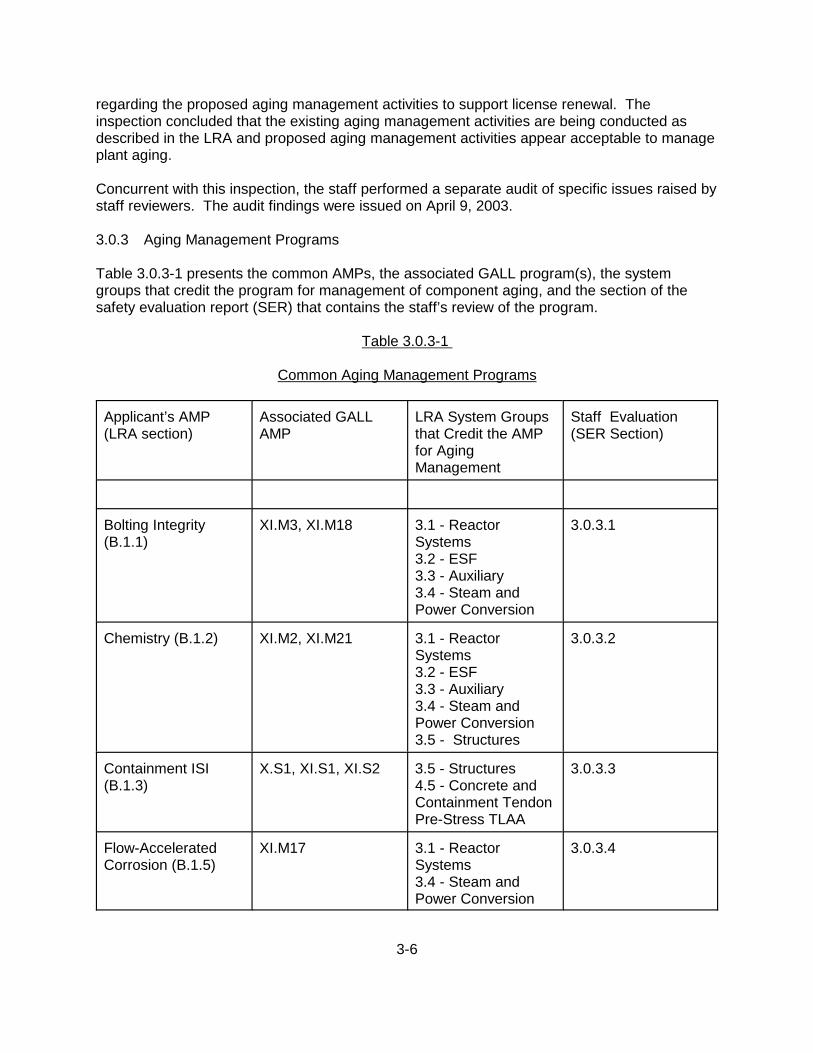
3-6
regarding the proposed aging management activities to support license renewal. Theinspection concluded that the existing aging management activities are being conducted asdescribed in the LRA and proposed aging management activities appear acceptable to manageplant aging.
Concurrent with this inspection, the staff performed a separate audit of specific issues raised bystaff reviewers. The audit findings were issued on April 9, 2003.
3.0.3 Aging Management Programs
Table 3.0.3-1 presents the common AMPs, the associated GALL program(s), the systemgroups that credit the program for management of component aging, and the section of thesafety evaluation report (SER) that contains the staff’s review of the program.
Table 3.0.3-1
Common Aging Management Programs
Applicant’s AMP(LRA section)
Associated GALLAMP
LRA System Groupsthat Credit the AMPfor AgingManagement
Staff Evaluation(SER Section)
Bolting Integrity(B.1.1)
XI.M3, XI.M18 3.1 - ReactorSystems3.2 - ESF3.3 - Auxiliary3.4 - Steam andPower Conversion
3.0.3.1
Chemistry (B.1.2) XI.M2, XI.M21 3.1 - ReactorSystems3.2 - ESF3.3 - Auxiliary3.4 - Steam andPower Conversion3.5 - Structures
3.0.3.2
Containment ISI(B.1.3)
X.S1, XI.S1, XI.S2 3.5 - Structures 4.5 - Concrete andContainment TendonPre-Stress TLAA
3.0.3.3
Flow-AcceleratedCorrosion (B.1.5)
XI.M17 3.1 - ReactorSystems3.4 - Steam andPower Conversion
3.0.3.4
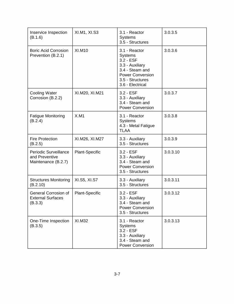
3-7
Inservice Inspection(B.1.6)
XI.M1, XI.S3 3.1 - ReactorSystems3.5 - Structures
3.0.3.5
Boric Acid CorrosionPrevention (B.2.1)
XI.M10 3.1 - ReactorSystems3.2 - ESF3.3 - Auxiliary3.4 - Steam andPower Conversion3.5 - Structures 3.6 - Electrical
3.0.3.6
Cooling WaterCorrosion (B.2.2)
XI.M20, XI.M21 3.2 - ESF3.3 - Auxiliary3.4 - Steam andPower Conversion
3.0.3.7
Fatigue Monitoring(B.2.4)
X.M1 3.1 - ReactorSystems4.3 - Metal FatigueTLAA
3.0.3.8
Fire Protection(B.2.5)
XI.M26, XI.M27 3.3 - Auxiliary 3.5 - Structures
3.0.3.9
Periodic Surveillanceand PreventiveMaintenance (B.2.7)
Plant-Specific 3.2 - ESF3.3 - Auxiliary3.4 - Steam andPower Conversion3.5 - Structures
3.0.3.10
Structures Monitoring(B.2.10)
XI.S5, XI.S7 3.3 - Auxiliary 3.5 - Structures
3.0.3.11
General Corrosion ofExternal Surfaces(B.3.3)
Plant-Specific 3.2 - ESF3.3 - Auxiliary3.4 - Steam andPower Conversion3.5 - Structures
3.0.3.12
One-Time Inspection(B.3.5)
XI.M32 3.1 - ReactorSystems3.2 - ESF3.3 - Auxiliary3.4 - Steam andPower Conversion
3.0.3.13

3-8
Selective Leaching(B.3.6)
XI.M33 3.2 - ESF3.3 - Auxiliary3.4 - Steam andPower Conversion3.5 - Structures
3.0.3.14
Table 3.0.3-2 presents the system-specific AMPs, the associated GALL program(s), the systemgroups that credit the program for management of component aging, and the SER section thatcontains the staff’s review of the program.
Table 3.0.3-2
System-Specific Management Programs
Applicant’s AMP(LRA section)
Associated GALLAMP
LRA System Groupsthat Credit the AMPfor AgingManagement
Staff Evaluation(SER Section)
Containment LeakRate (B.1.4)
XI.S1, XI.S4 3.5 - Structures 3.5.2.3.1
Reactor VesselIntegrity (B.1.7)
XI.M31 3.1 - ReactorSystems
3.1.2.3.1
Diesel FuelMonitoring andStorage (B.2.3)
XI.M30 3.3 - AuxiliarySystems
3.3.2.3.1
Overhead LoadHandling SystemsInspection (B.2.6)
XI.M23 3.3 - AuxiliarySystems
3.5.2.3.2
Reactor VesselInternals Inspection(B.2.8)
XI.M13, XI.M16 3.1 - ReactorSystems
3.1.2.3.2
Steam Generator(B.2.9)
XI.M19 3.1 - ReactorSystems
3.1.2.3.3
Alloy 600 (B.3.1) XI.M11 3.1 - ReactorSystems
3.1.2.3.4
Buried SurfacesExternal Corrosion(B.3.2)
XI.M34 3.3 - AuxiliarySystems
3.3.2.3.2
3-9
Non-EQ Cable AgingManagement (B.3.4)
XI.E1, XI.E2, XI.E3 3.6 - Electrical andI&C Systems
3.6.2.3.1
ThermalEmbrittlement ofCast AusteniticStainless Steel(B.3.7)
XI.M12 3.1 - ReactorSystems
3.1.2.3.5
3.0.3.1 Bolting Integrity Program
3.0.3.1.1 Summary of Technical Information in the Application
The applicant’s bolting integrity program is discussed in LRA Section B.1.1, “Bolting IntegrityProgram.” The applicant states that the program is consistent with GALL programs XI.M3,“Reactor Head Closure Studs,” and XI.M18, “Bolting Integrity,” with the exception that theapplicant did not identify stress corrosion cracking (SCC) as an aging effect requiringmanagement for high-strength carbon steel bolting in plant indoor air. The applicant also statesthat it will utilize American Society of Mechanical Engineers (ASME) Section XI, SubsectionIWF, visual VT-3 inspection requirements rather than volumetric inspections for the inspectionof supports.
This AMP is credited with managing aging in bolts in the reactor, ESF, auxiliary, and steam andpower conversion systems.
The applicant performed inspections of bolted components under the FCS inservice inspection(ISI) program, the boric acid corrosion (BAC) prevention program, and the structures monitoring program (SMP). The SMP inspects structural bolts. Visual inspections conducted under theBAC prevention program included the inspection of bolted components in borated systems. Any indication of boric acid residue or damage is reported and evaluated to determine if acomponent can remain in service per established procedures. Documentation of operatingexperience is included as part of the BAC prevention program. On occasion, visualobservations have identified BAC damage. These deficiencies were documented inaccordance with the FCS corrective action program (CAP) and resulted in repair orreplacement, if required. Review of the plant-specific operating experience indicates that theinspections have been effective in managing the aging effects of bolted components.
3.0.3.1.2 Staff Evaluation
In LRA Section B.1.1, “Bolting Integrity Program,” the applicant described its AMP to manageaging in bolting. The LRA stated that this AMP is consistent with GALL AMPs XI.M3, “ReactorHead Closure Studs,” and XI.M18, “Bolting Integrity,” with the exception that the applicant didnot identify SCC as an aging effect requiring management for high-strength carbon steel boltingin plant indoor air. The applicant also stated that it will utilize ASME Section XI, SubsectionIWF, visual VT-3 inspection requirements, rather than volumetric inspections, for the inspectionof supports. The staff confirmed the applicant’s claim of consistency during the AMRinspection. Furthermore, the staff reviewed the deviation and its justification to determinewhether the AMP, with the deviation, remains adequate to manage the aging effects for which it

3-10
is credited, and reviewed the USAR Supplement to determine whether it provides an adequatedescription of the revised program.
In RAI B.1.1-1, issued by letter dated October 11, 2002, the staff requested that the applicantaddress its statement in Section B.1.1 of the LRA, that the bolting integrity program isconsistent with the GALL Report, with the exception that FCS has not identified SCC as acreditable aging effect requiring management for high-strength carbon steel bolting in plantindoor air. The staff indicated that its understanding is that this exception means that thisprogram will follow all the requirements in NUREG-1801, “Generic Aging Lessons Learned(GALL) Report,” dated July 2001, with the exception of high-strength carbon steel bolting forsteel structures, pipe supports, heating, ventilation, and air conditioning (HVAC) supports,electrical supports, and equipment supports. The staff requested that the applicant verify thatthe staff’s understanding of the program is correct. The applicant’s response by letter datedDecember 19, 2002, stated that the NRC staff’s understanding of the program is correct. However, the applicant, in its response, did not discuss the exclusion of the aging effect of SCCregarding high-strength carbon steel bolting in plant indoor air or why an ASME Section XI,Subsection IWF, visual VT-3 inspection, rather than volumetric inspections, is adequate toinspect supports.
By letter dated February 20, 2003, the staff, in potential open item (POI)-7(a), requested thatthe applicant provide the basis for the exclusion of SCC as a plausible aging effect for high-strength carbon steel bolting in plant indoor air, as well as the basis for why a VT-3 inspection issufficient to inspect supports. By letter dated March 14, 2003, the applicant clarified that thebasis for excluding SCC as a plausible aging effect for high-strength carbon steel bolting inplant indoor air can be found in the response to RAI 3.2.1-2, submitted by the staff by letterdated December 12, 2002. In the response to RAI 3.2.1-2, the applicant stated that stainlesssteels, high-strength aluminum alloys, and brasses are the most susceptible alloys to SCC. Ordinary steels are not as susceptible. Secondly, SCC requires exposure to specific chemicalsolutions for the mechanism to occur. Stainless steels require chloride-laden solutions. Aluminum alloys require sodium chloride solutions. Brasses require ammonia solutions. Ordinary steels require exposure to caustic or mixed acid solutions. Thirdly, elevatedtemperature is usually a factor when SCC occurs. Thus, for the carbon steel bolting inquestion, SCC is not an issue because (1) the material is not readily susceptible to SCC, (2) acaustic or mixed acid solution environment is not present, and (3) elevated temperatures arenot present. With regard to VT-3 inspections, in its response to POI-7(a), the applicant statedthat support bolting does not perform a pressure-retention function like flange bolting, pumpcasing bolting, etc.
The staff has reviewed the applicant’s response to POI-7(a) and RAI 3.2.1-2 and agrees thatthe conditions and environments needed for SCC to occur in high-strength carbon steel boltingin plant indoor air are not present at FCS. In addition, the staff agrees that the function of thesupport bolting does not warrant a volumetric inspection, and that a VT-3 inspection issufficient. POI-7(a) is resolved.
The staff reviewed the applicant’s operating experience with regard to the management ofbolted components, as provided in LRA Section B.1.1. LRA Section B.1.1 states thatinspections of bolted components have been conducted under the FCS ISI program, BACprevention program, and the SMP. On occasion, visual observations have identified BACdamage. These deficiencies were documented in the FCS CAP and resulted in repair or

3-11
replacement, if required. The applicant concludes, and the staff agrees, that the plant-specificoperating experience indicates that visual inspections have proved effective in managing theaging effects of bolted components.
LRA Section A.2.2 provides the applicant’s USAR Supplement describing the bolting integrityprogram. The staff reviewed the USAR Supplement and finds it to be an adequate descriptionof the bolting integrity program.
3.0.3.1.3 Conclusions
On the basis of its review and inspection of the applicant’s program, the staff finds that thoseportions of the program for which the applicant claims consistency with GALL are consistentwith GALL. In addition, the staff has reviewed the exceptions to the GALL program and findsthat the applicant’s program provides for adequate management of the aging effects for whichthe program is credited. The staff also reviewed the USAR Supplement for this AMP and findsthat it provides an adequate summary description of the program, as required by 10 CFR54.21(d).
Therefore, on the basis of its review, the staff concludes that the applicant has demonstratedthat the bolting integrity program will effectively manage aging in the structures andcomponents for which this program is credited so that the intended functions of the associatedcomponents and systems will be maintained consistent with the CLB for the period of extendedoperation, as required by 10 CFR 54.21(a)(3).
3.0.3.2 Chemistry Program
3.0.3.2.1 Summary of Technical Information in the Application
The applicant’s water chemistry program is discussed in LRA Section B.1.2, “ChemistryProgram.” The applicant states that the program is consistent with GALL program XI.M2,”Water Chemistry,” and includes the chemistry-related portions of the program in GALL XI.M21,“Closed-Cycle Cooling Water System.” This extends its applicability to the systems containingclosed-cycle cooling water.
This AMP is credited with managing aging effects caused by primary and secondary waterchemistries, and by the water chemistry in the component cooling water (CCW) system. It isbased on the Electric Power Research Institute (EPRI) water chemistry guidelines. Theseguidelines are referenced in the following EPRI reports, Topical Report (TR)-105714 for primarywater chemistry, TR-102134 for secondary water chemistry, and TR-107396 for closed-cyclecooling water chemistry.
The chemistry program will also manage the aging effects on components which either are notevaluated in GALL, or, although not specifically evaluated, are relying on the AMPs in GALL. These components are listed in Tables 3.1-2 through 3.5-2 and Tables 3.1-3 through 3.5-3 ofthe LRA. They are included in reactor systems, engineering safety features systems, auxiliarysystems, steam and power conversion systems, and containment, structures and componentsupports. The components are made of carbon steel, stainless steel, cast austenitic stainlesssteel (CASS), low-alloy steel, cast iron, and nickel-based and copper alloys. When exposed tothe environments of primary, secondary, or closed-cycle cooling water, the resulting aging

3-12
effect is cracking and loss of material caused by general, crevice, pitting, galvanic, andmicrobiologically-influenced corrosion. The chemistry program manages these aging effects byspecifying water chemistries which minimize corrosive damage.
3.0.3.2.2 Staff Evaluation
In LRA Section B.1.2, “Chemistry Program,” the applicant described its AMP to manage agingeffects by controlling primary, secondary, and closed-cycle cooling water chemistries. The LRAstated that this AMP is consistent with the chemistry program in Section XI.M2 of the GALLReport with an enhancement resulting from the inclusion of the chemistry-related portions of theGALL closed-cycle cooling water system program. The staff confirmed the applicant’s claim ofconsistency during the AMR inspection. Furthermore, the staff reviewed the enhancement andits justification to determine whether the AMP, with the enhancement, remains adequate tomanage the aging effects for which it is credited. The staff also reviewed the USARSupplement to determine whether it provides an adequate description of the program.
The inclusion of the information discussed above causes changes in some attributes of theGALL chemistry program. Therefore, the staff reviewed this AMP against only those attributesof the applicant’s program which deviate from the attributes of the GALL chemistry program,using the guidance in BTP RLSB-1 in Appendix A of the SRP-LR.
[Preventive Actions] In addition to controlling water chemistry to minimize exposure of theaffected components to aggressive chemistry environments, the preventive action attribute ofthe water chemistry program in the LRA also addresses maintaining proper corrosion inhibitorconcentrations in the closed-cycle cooling water systems. The staff finds that this additionalrequirement in the applicant’s chemistry program extends its preventive function to the closed-cycle cooling water systems, and therefore, finds it acceptable.
[Monitoring and Trending] The monitoring and trending attribute in the water chemistryprogram in GALL is modified by specifying the need for sampling water chemistry on acontinuous, daily, weekly, or as needed basis, as indicated by plant operating conditions. Thestaff finds this modification acceptable because it will improve aging management by closelymaintaining controlled water chemistry.
[Acceptance Criteria] The acceptance criteria in the GALL water chemistry program areextended by requiring the water in the closed-cooling water system to maintain concentrationsof corrosion inhibitors within the specified limits of EPRI TR-107396. The staff finds thismodification acceptable because it will ensure that the corrosion damage to the components inthis system will be minimized.
[Operating Experience] The plant operating experience has indicated that over the operatinghistory of the plant, several incidents have occurred which could be attributed to improper waterchemistry. These included steam generator (SG) tube leaks, condenser tube leaks, and someresin intrusion into the primary storage tank. However, in all cases, proper corrective actionswere implemented to prevent reoccurrence. In addition, the chemistry management of agingeffects was continuously upgraded based on plant personnel and industry experience.

3-13
Such operating experience has provided feedback to revisions of the EPRI water chemistryguideline document. The staff concluded that the EPRI guideline document, which wasdeveloped based on operating experience, has been effective over time with widespread use.
3.0.3.2.3 Conclusions
On the basis of its review and inspection of the applicant’s AMP, including the proposedenhancements to the AMP, the staff finds that those portions of the program for which theapplicant claims consistency with GALL are consistent with GALL. The staff also reviewed theUSAR Supplement for this AMP, and finds that it provides an adequate summary description ofthe program, as required by 10 CFR 54.21(d).
Therefore, on the basis of its review, the staff concludes that the applicant has demonstratedthat the chemistry program will effectively manage aging in the structures and components forwhich this program is credited so that the intended functions of the associated components andsystems will be maintained consistent with the CLB for the period of extended operation, asrequired by 10 CFR 54.21(a)(3).
3.0.3.3 Containment Inservice Inspection Program
The applicant described its containment ISI program in Section B.1.3 of the LRA. The applicantcredits this program with managing the aging of containment structures and components thatare within the scope of license renewal. The staff reviewed the containment ISI program todetermine whether the applicant has demonstrated that the program will adequately managethe applicable effects of aging during the period of extended operation, as required by 10 CFR54.21(a)(3).
3.0.3.3.1 Summary of Technical Information in the Application
The LRA states that the FCS containment ISI program is consistent with GALL programs X.S1,“Concrete Containment Tendon Prestress,” XI.S1, “ASME Section XI, Subsection IWE,” andXI.S2, “ASME Section XI, Subsection IWL.” The 10-year containment (IWE and IWL) ISIprogram plan for FCS, incorporating the examination requirements of Subsection IWE andSubsection IWL of the Code, has been developed and implemented.
As part of the operating experience, the applicant states that inspections of the containmentliner have been conducted in accordance with the containment leak rate testing program andthe maintenance rule implementation program. Inspections of the tendons and tendonanchorages have been conducted in accordance with technical specifications, the USAR, andplant procedures. Furthermore, the applicant states that the ASME Code, Section XI,Subsection IWL, ISI program incorporates all of the inspection criteria and guidelines of theprevious tendon inspection program and is implemented using existing plant procedures. Nosignificant age-related degradation has been identified in the inspections performed.
3.0.3.3.2 Staff Evaluation
LRA Section B.1.3 describes the applicant’s containment ISI program. The LRA states that thisAMP is consistent with GALL programs X.S1, “Concrete Containment Tendon Prestress,”XI.S1, “ASME Section XI, Subsection IWE,” and XI.S2, “ASME Section XI, Subsection IWL,”

3-14
with no deviations. The staff also reviewed the USAR Supplement to determine whether itprovides an adequate description of the program.
In addition to the review of Section B.1.3 of the LRA, the staff reviewed the relevant portions ofSection 3.5, “Aging Management of Containment, Structures, and Component Supports,” of theLRA to correlate the results of the AMR of the containment components with the ISI programdescribed in Section B.1.3 of the LRA.
The applicant’s containment ISI program is consistent with the provisions of GALL programsXI.S1 and XI.S2. Moreover, for the prestressing tendons of the FCS containment, theapplicant’s prestressing tendon monitoring program is consistent with GALL program X.S1. Ingeneral, the staff considers the use of these GALL programs appropriate and acceptable. Plant-specific implementation is discussed below.
To assess the present condition of the containment liner plate, the staff asked the applicant, inRAI B.1.3-1, to provide a summary of the significant degradations (i.e., metal thinning in excessof 10 percent of the nominal thickness of the metal) discovered during the last inspection of theliner, and a summary of corrective actions taken. By letter dated December 19, 2002, theapplicant provided the following response:
Inspections of the liner performed in May 2001 identified approximately 6 locations of corrosion andloss of material at the base of the liner, between the floor expansion seal and the curb at elevation994’ 6”. The total area of corrosion was less than 6 square inches. Inspection identified small areaswithin the corroded areas with a maximum thickness loss of approximately 15%. The minimumthickness measured with [ultrasonic testing] UT was 0.216" compared to a nominal thickness of 0.25".The inspection identified some areas of seal separation from the liner and shrinkage below the curb,which allowed moisture to collect. Repairs were made to recoat the degraded areas of the liner andrestore degraded areas of the moisture barrier during the 2002 refueling outage. This includedremoval of the top portion of the moisture barrier to inspect inaccessible sections of the liner. Onlyminor surface corrosion was found on the liner extending only 0.125" to 0.25" below the top of theexisting joint sealer. FCS plans to reperform the liner inspection during the 2003 refueling outage.
Since the applicant is monitoring the liner condition as part of its ISI program, and maintainingthe moisture barrier through periodic inspections, the staff believes that significant linerdegradation will be monitored and corrective actions will be taken so that the integrity of thecontainment, as required by the CLB, will be maintained during the period of extendedoperation.
For inspection of concrete components of the FCS containment, the applicant is committing touse GALL program XI.S2, “ASME Section XI, Subsection IWL,” during the period of extendedoperation. The GALL program recognizes the absence of explicit acceptance criteria forconcrete components (in Element 6, Acceptance Criteria), and recommends the use of Chapter5 of American Concrete Institute (ACI) 349.3R. By letter dated February 20, 2003, the staffissued POI-7(b), requesting the applicant to provide information regarding the acceptancecriteria to be used for examination of the containment concrete at FCS. By letter dated March14, 2003, the applicant stated that the FCS containment ISI program meets the requirements ofASME Section XI, Subsection IWL, and is consistent with the criteria specified in GALLprogram XI.S2, “ASME Section XI, Subsection IWL.” In Appendix B of the March 14, 2003,letter, the applicant provided a copy of the vendor procedure used for the ASME XI, SubsectionIWL, inspection performed in 2001. The staff reviewed the information provided in response toPOI-7(b) and finds it acceptable because the vendor’s process for examination of concrete

3-15
surfaces of the FCS containment clearly delineates the responsibility, qualifications, qualitycontrol, and examination standards to be used for the examination. POI-7(b) is resolved.
In the 1990s, NRC staff inspections had noted a large amount of grease leakage from thetendons, specifically in the ring-girder areas of the FCS containment. In RAI B.1.3-2, the staff asked the applicant to provide an assessment of such leakage on tendon performance (i.e.,absence of corrosion protection and potential degradation of tendon wires) during the period ofextended operation, and the effectiveness of the actions taken to alleviate future greaseleakage. By letter dated December 19, 2002, the applicant provided the following response:
Grease leakage noted on the outer containment walls during the 1990’s resulted from seal leakagefrom helical tendon upper grease cans. The leakage characterized as a “large amount” ranges froma few cups to one gallon from a typical volume of more than 50 gallons. This upper seal can leakagehas no effect on the long term corrosion of the tendon wires or end attachment, as demonstrated byinspection of the tendon ends when the leaks were repaired. The grease fill procedure was modifiedto leave additional “head space” for thermal expansion to decrease the number of minor grease leakson the containment upper helical can seals.
IN 99-10, “Degradation of Prestressing Tendon Systems in Prestressed Concrete Containments,”identified examples of tendon degradation due to loss of grease. Our saw tooth construction andunique helical tendon design combine to make many of the aspects of the subject information noticenot applicable to FCS. No damage to tendon wires due to lack of grease, corrosion, or other agingeffects have been identified during tendon inspections performed at FCS. To investigate the anti-corrosion effectiveness of thin films of grease, OPPD committed to the NRC in 1992 to test a dometendon that had lost a significant amount of grease. The results of surveillance testing of the dometendon showed enough grease adheres to the tendon wires to protect them from corrosion even whenlarge grease voids occur. The type of grease was not changed.
The staff believes that the example of wire breakage at the Calvert Cliffs Nuclear Power Plant(described in information notice (IN) 99-10) is applicable to FCS containment tendon wires, andthe potential for corrosion-induced wire breakage is a plausible aging effect. However, theapplicant is aware of the problem, and since the tendon wires will be monitored during the IWLexaminations, the staff finds the applicant’s process for addressing this issue acceptable.
The staff reviewed the applicant’s operating experience as provided in LRA Section B.1.3 whichstates that inspections have been conducted of the containment liner, tendons, and tendonanchorages and no age-related degradation of these components was found. The applicantconcludes, and the staff agrees, that the plant-specific operating experience indicates thatinspections have proved effective in managing the aging effects associated with componentswithin the scope of the containment ISI program.
The applicant provided a summary description of the containment ISI program in Section A.2.6of the LRA. The staff finds that the summary description contains a sufficient level ofinformation, as required by 10 CFR 54.21(d), and is acceptable.
3.0.3.3.3 Conclusion
On the basis of its review and inspection of the applicant’s program, and the applicant’sresponses to the staff’s RAIs, the staff finds that those portions of the program for which theapplicant claims consistency with GALL are consistent with GALL. The staff also reviewed theUSAR Supplement for this AMP and finds that it provides an adequate summary description ofthe program, as required by 10 CFR 54.21(d).

3-16
Therefore, on the basis of its review, the staff concludes that the applicant has demonstratedthat the containment ISI program will effectively manage aging in the structures andcomponents for which this program is credited so that the intended functions of the associatedcomponents and systems will be maintained consistent with the CLB for the period of extendedoperation, as required by 10 CFR 54.21(a)(3).
3.0.3.4 Flow-Accelerated Corrosion Program
3.0.3.4.1 Summary of Technical Information in the Application
The applicant’s FAC program is discussed in LRA Section B.1.5, “Flow-Accelerated CorrosionProgram.” The applicant states that the program is consistent with GALL program XI.M17,“Flow-Accelerated Corrosion.”
This AMP is credited with managing aging effects in components which, although notspecifically evaluated, are relying on the aging management of the FAC program in GALL. These components are listed in Tables 3.1-3 and 3.4-3 of the LRA. They are included inreactor and steam and power conversion systems. The components susceptible to FAC aremade of carbon and low-alloy steel and are affected by FAC when exposed to the environmentsof deoxygenated water or saturated steam. The resulting aging effects are caused by loss ofmaterial.
The applicant’s program for controlling FAC relies on the implementation of the EPRI guidelinescontained in NSAC-202L-R2, “Recommendation for an Effective Flow-Accelerated CorrosionProgram.” The program includes procedures and administrative controls to ensure structuralintegrity of all carbon or low-alloy lines containing high-energy fluids. The applicant ascertainsthat all aging effects caused by FAC are properly managed by using predictive codes andinspection procedures which include wall thickness measurements. The applicant uses twocodes: CHECWORKS, developed by EPRI, and FACManager which supplements theCHECWORKS code predictions. Using these two codes and performing measurements, theapplicant can make timely predictions of loss of material by FAC so that the damagedcomponents can be repaired or replaced before their failure.
3.0.3.4.2 Staff Evaluation
In LRA Section B.1.5, “Flow-Accelerated Corrosion Program,” the applicant described its AMPto manage aging effects caused by FAC. The LRA stated that this AMP is consistent withGALL AMP XI.M17, “Flow-Accelerated Corrosion Program,” with no deviations. The staffconfirmed the applicant’s claim of consistency during the AMR inspection. The staff reviewedthe applicant’s description of the program in the LRA and evaluated the applicant’s responsesto the staff’s RAI B.1.5-1, issued by letter dated October 11, 2002. This RAI requested theapplicant to identify the methods used for predicting component degradation by FAC, asdiscussed in NSAC-202L-R2. By letter dated December 19, 2002, the applicant stated that ithad performed a susceptibility analysis to identify components susceptible to degradation byFAC. Components that are suitable for modeling are modeled using CHECWORKS. Inaddition, all inspection methods are stored in a Microsoft Access-based program calledFACManager, which was purchased from a vendor with considerable FAC expertise. FACManager calculates wear using the same equations as CHECWORKS, but calculates wearby a straight line wear over time formula, which is the average wear rate over the components’

3-17
life (or the time between inspections if the point-to-point method is used). For non-modeledcomponents, FACManager is used to predict component degradation rates. For modeledcomponents, both FACManager and CHECWORKS results are used in determining thecomponent degradation rates.
On the basis of the staff’s review, including the applicant’s response to RAI B.1.5-1, the stafffinds that the applicant’s program is consistent with the GALL program. Therefore, the staffdetermined that there is no need for the staff to review the attributes in the applicant’s FACprogram, with the exception of plant-specific operating experience. The staff also reviewed theUSAR Supplement to determine whether it provides an adequate description of the program.
[Operating Experience] The plant operating experience, described in the LRA, has indicatedthat on some occasions pipe wall thickness has been found to be below the establishedscreening criteria, and visual inspections have identified through-wall erosion. Thesedeficiencies were documented and the damaged components were repaired or replaced. Amajor rupture of an extraction steam line occurred in 1997. As a result of that occurrence, theFAC program was upgraded. The current program follows the EPRI guidelines. The staff findsthis approach acceptable because, by following current procedures, the applicant ensures thatthe FAC program will properly manage aging effects due to FAC.
The applicant provided its USAR Supplement for the FAC program in Section A.2.12 of theLRA. The staff reviewed the USAR Supplement and finds that the summary descriptioncontains a sufficient level of information, as required by 10 CFR 54.21(d), and is acceptable.
3.0.3.4.3 Conclusions
On the basis of its review and inspection of the applicant’s program, the staff finds that thoseportions of the program for which the applicant claims consistency with GALL are consistentwith GALL. The staff also reviewed the USAR Supplement for this AMP and finds that itprovides an adequate summary description of the program, as required by 10 CFR 54.21(d).
Therefore, on the basis of its review, the staff concludes that the applicant has demonstratedthat the FAC program will effectively manage aging in the structures and components for whichthis program is credited so that the intended functions of the associated components andsystems will be maintained consistent with the CLB for the period of extended operation, asrequired by 10 CFR 54.21(a)(3).
3.0.3.5 Inservice Inspection Program
3.0.3.5.1 Summary of Technical Information in the Application
The applicant’s ISI program is discussed in LRA Section B.1.6, “Inservice Inspection Program.” The applicant states that the program is consistent with GALL programs XI.M1, “ASME SectionXI, Inservice Inspection, Subsections IWB, IWC, and IWD,” and XI.S3, “ASME Section XI,Subsections IWF.” The applicant also states that the scope of the FCS ISI program includesthose plant-specific components identified in Tables 3.1-2 and 3.2-3 of the LRA for which theISI program is identified as an AMP.
3-18
As part of the operating experience, the applicant states that the FCS ISI program has beeneffective in managing the aging effects of components. No significant age-related degradationhas been identified in the inspections performed.
3.0.3.5.2 Staff Evaluation
The applicant states that the program is consistent with GALL program XI.M1, "ASME SectionXI Inservice Inspection, Subsections IWB, IWC, and IWD," and XI.S3, "ASME Section XI,Subsections IWF," with no deviations. The staff confirmed the applicant’s claim of consistencyduring the AMR inspection. The staff concludes that the applicant’s program is consistent withthe GALL program. There is no need, therefore, for the staff to review the attributes in theapplicant’s ISI program, with the exception of plant-specific operating experience. The staffalso reviewed the USAR Supplement for this AMP and finds that it provides an adequatesummary description of the program, as required by 10 CFR 54.21(d).
[Operating Experience] The plant operating experience, described in the LRA, has indicatedthat there was no significant age-related degradation identified through inservice inspection ofcomponents performed during the past inspection intervals. The FCS ISI program has beeneffective in managing the aging effects of those components and their integral supportsidentified in Tables 3.1-2 and 3.2-3 of the LRA for which the ISI program is identified as anAMP. The staff, therefore, has determined that the applicant’s ISI program will adequatelymanage the aging effects in the components identified in the tables during the period ofextended operation.
3.0.3.5.3 Conclusion
On the basis of its review and inspection of the applicant’s program, the staff finds that thoseportions of the program for which the applicant claims consistency with GALL are consistentwith GALL. The staff also reviewed the USAR Supplement for this AMP and finds that itprovides an adequate summary description of the program, as required by 10 CFR 54.21(d).
Therefore, on the basis of its review, the staff concludes that the applicant has demonstratedthat the ISI program will effectively manage aging in the structures and components for whichthis program is credited so that the intended functions of the associated components andsystems will be maintained consistent with the CLB for the period of extended operation, asrequired by 10 CFR 54.21(a)(3).
3.0.3.6 Boric Acid Corrosion Prevention Program
3.0.3.6.1 Summary of Information in the Application
The applicant’s BAC prevention program is discussed in LRA Section B.2.1, “Boric AcidCorrosion Prevention Program.” The applicant states that the program is consistent with GALLprogram XI.M10, “Boric Acid Corrosion,” with several enhancements which will be made priorto the period of extended operation.
The AMP is credited with managing the aging effects in the systems carrying water containingboric acid. The program will manage the aging effects in the components which either are notevaluated in GALL, or, although not specifically evaluated, are relying on the AMPs in GALL.
3-19
These components are listed in Tables 3.1-2, 3.1-3, and 3.3-3 of the LRA. They are included in the reactor and auxiliary systems. The components are made of carbon steel, low-alloy steel,cast iron, cadmium plated steel, galvanized steel, and copper alloys. When exposed to leakageof boric acid, the resulting aging effect is loss of material.
The program relies on implementation of the recommendations of NRC Generic Letter (GL) 88-05 to monitor the condition of the reactor coolant pressure boundary for boric acid leaks. Periodic visual inspections of adjacent structures, components, and supports for evidence ofleakage and corrosion are the elements of the program.
3.0.3.6.2 Staff Evaluation
In LRA Section B.2.1, “Boric Acid Corrosion Prevention Program,” the applicant described itsAMP to manage aging effects due to boric acid leakage. The LRA stated that this AMP isconsistent with GALL AMP XI.M10, “Boric Acid Corrosion,” with enhancements that will bemade prior to the period of extended operation. The enhancements increase the scope ofinspections and provide specific guidance to the inspectors. The staff confirmed the applicant’sclaim of consistency during the AMR inspection.
The inclusion of the information discussed above causes changes in some attributes of theGALL BAC prevention program. Therefore, the staff reviewed this AMP against only thoseattributes of the applicant’s program which deviate from the attributes of the GALL’s BACprogram, defined in BTP RLSB-1, found in Appendix A of the SRP-LR. The staff also reviewedthe USAR Supplement to determine whether it provides an adequate description of theprogram.
[Scope of Program] The applicant added to the scope of the GALL BAC program, specificguidance for inspection of the components, structures, and electrical components where boricacid may have leaked. It also added the need for inspecting the fuel pool cooling and wastedisposal systems. The staff finds this acceptable because these additional inspections willmake the program more comprehensive, and improve the management of aging effects in thecomponents potentially exposed to boric acid leaks.
[Parameters Monitored or Inspected] The applicant’s BAC prevention program specifies theparameters monitored and inspected, with an enhancement to include the spent fuel poolcooling and waste disposal systems to the scope of the program. The staff finds thisacceptable because this will broaden the program and enhance the program for managing theexisting aging effects.
[Monitoring and Trending] The monitoring and trending attribute in the applicant’s program willbe enhanced by implementing specific guidance to require maintenance personnel to reportboric acid leakage to the BAC prevention program engineer. These procedures will improve theway the plant systems containing boric acid are monitored and trended, and will contribute tobetter management of the aging effects caused by boric acid corrosion. Therefore, the stafffinds this enhancement acceptable.
[Operating Experience] The plant operating experience included severe boric acid corrosion ofpump studs, which prompted the applicant to introduce significant improvement to its BACprevention program. The staff agrees with the applicant that the current program routinely

3-20
identifies and corrects borated water leakage in the RCS and other systems carrying boratedwater, and adequately manages aging effects caused by boric acid corrosion.
The applicant provided its USAR Supplement for the BAC prevention program in Section A.2.3of the LRA. The staff reviewed the USAR Supplement and finds that the summary descriptioncontains a sufficient level of information, as required by 10 CFR 54.21(d), and is acceptable.
The staff is currently reviewing the issues associated with NRC Bulletin 2002-01. This bulletinwas issued as a result of a control rod drive mechanism nozzle cracking event at Davis Besse,which resulted in severe degradation of the reactor vessel head due to exposure toconcentrated boric acid. To date, all licensees (except Davis Besse) have responded to thebulletin, providing information about their boric acid corrosion control programs. Any futureregulatory actions that may be required as a result of those reviews will be addressed by thestaff in a separate regulatory action. This is considered a current operating issue and will behandled as such. The staff will resolve this issue in accordance with 10 CFR 54.30 outside ofthe license renewal process.
3.0.3.6.3 Conclusions
On the basis of its review and inspection of the applicant’s program, the staff finds that thoseportions of the program for which the applicant claims consistency with GALL are consistentwith GALL. In addition, the staff has reviewed the enhancements to the GALL program andfinds that the applicant’s program provides for adequate management of the aging effects forwhich the program is credited. The staff also reviewed the USAR Supplement for this AMP andfinds that it provides an adequate summary description of the program, as required by 10 CFR54.21(d).
Therefore, on the basis of its review, the staff concludes that the applicant has demonstratedthat the BAC prevention program will effectively manage aging in the structures andcomponents for which this program is credited so that the intended functions of the associatedcomponents and systems will be maintained consistent with the CLB for the period of extendedoperation, as required by 10 CFR 54.21(a)(3).
3.0.3.7 Cooling Water Corrosion Program
3.0.3.7.1 Summary of Technical Information in the Application
The applicant’s cooling water corrosion program is discussed in LRA Section B.2.2, “CoolingWater Corrosion Program.” The applicant states that the program is consistent with GALLprogram XI.M20,”Open-Cycle Cooling Water System,” modified by moving the reference toexternal coatings to Section B.3.3, “General Corrosion of External Surfaces Program,” in theLRA. The cooling water corrosion program is also consistent with the non-chemistry relatedportions of GALL program XI.M21, “Closed-Cycle Cooling Water System,” modified byremoving from the license renewal commitments reference to (1) fluid flow, which is an activefunction, and (2) testing the systems performing active functions.
This AMP is credited with managing aging effects in the open-cycle and closed-cycle coolingwater systems.

3-21
The cooling water corrosion program will also manage the aging effects in the componentswhich are either not evaluated in GALL, or, although not specifically evaluated, are relying onthe AMP in GALL. These components are listed in Tables 3.2-2, 3.3-2, and 3.3-3 of the LRA. They are included in the sections of the LRA addressing the ESF and auxiliary systems. Thesecomponents are made from Alloy 600, brass, bronze, copper and copper alloy, nickel-basedalloy, carbon and stainless steel, and cast iron. They are exposed to the environments ofcorrosion-inhibited treated water, oxygenated or deoxygenated treated water, and raw water.
The resulting aging effects are caused by cracking and by loss of material due to crevice,pitting, galvanic, general, and microbiologically-influenced corrosion, and biofouling. The agingmanagement activities of the applicant’s cooling water corrosion program is based on the EPRIguidelines in TR-107396.
3.0.3.7.2 Staff Evaluation
In LRA Section B.2.2, “Cooling Water Corrosion Program,” the applicant described its AMP tomanage aging effects due to corrosion. The LRA stated that this AMP is consistent with GALLprogram XI.M20,”Open-Cycle Cooling Water System,” modified by moving the reference toexternal coatings to Section B.3.3, “General Corrosion of External Surfaces Program,” in theLRA. The cooling water corrosion program is also consistent with the non-chemistry relatedportions of GALL program XI.M21, “Closed-Cycle Cooling Water System,” modified byremoving from the license renewal commitments reference to (1) fluid flow, which is an activefunction, and (2) testing the systems performing active functions. The staff confirmed theapplicant’s claim of consistency during the AMR inspection. The chemistry-related portions ofXI.M21 are addressed in the FCS chemistry program (LRA Section B.1.2) which is evaluated bythe staff in Section 3.0.3.2 of this SER.
The deviations of the program caused changes in some attributes of the GALL open-cycle andclosed-cycle cooling water system programs. Therefore, the staff reviewed this AMP againstonly those attributes of the applicant’s programs which deviate from the attributes of the GALL’sopen- and closed-cycle cooling water system programs, as defined in BTP RLSB-1, found inAppendix A of the SRP-LR. The staff also reviewed the USAR Supplement to determinewhether it provides an adequate description of the program.
[Scope of Program] The scope of the applicant’s cooling water corrosion program consists ofthe scope of GALL program, augmented by additional inspections of various raw water andclosed-cycle cooling system components based on a susceptibility evaluation. The staff findsthis acceptable because including these additional inspections makes the program morecomprehensive and ensures better management of the aging effects.
[Preventive or Mitigative Actions] The preventive actions attribute in the applicant’s program ismodified by removing the chemistry-related portions in the GALL’s closed-cycle cooling waterprogram. The preventive actions specified in the removed portions address the need formaintaining corrosion inhibitor concentrations within specified limits, and monitoring andcontrolling cooling water chemistry. The staff finds this modification acceptable because thesepreventive actions are addressed in the applicant’s chemistry program.
[Parameters Monitored or Inspected] The parameters monitored or inspected attribute in theapplicant’s program is modified by removing the need for monitoring and inspecting external

3-22
coatings in the GALL’s open-cycle cooling water system and relaxing the requirements for thefrequency of monitoring in the closed-cycle cooling water system. The staff finds thisacceptable because external coatings are addressed in the applicant’s general corrosion ofexternal surfaces program, and the need for specific monitoring frequency is not required bythe EPRI guidelines on which the program is based.
[Detection of Aging Effects] The detection of aging effects attribute in the applicant’s programis modified by removing the need for detecting aging effects caused by defective externalprotective coatings in the open-cycle cooling water system and by the addition, to both theopen- and closed-cycle cooling water systems of more component inspections based on asusceptibility evaluation. The detection of aging effects caused by defective external protectivecoatings is addressed in the applicant’s general corrosion of external surfaces program, andadditional inspections will improve detection of the aging effects. Therefore, the staff finds thedeviation from the GALL program to be acceptable.
[Monitoring and Trending] The monitoring and trending attribute is required to demonstratesystem capability to remove heat from the cooling water. In the applicant’s program, thisconsists of modifying the GALL attribute to add inspections of various components in the open-cycle and closed-cycle cooling water systems, based on evaluations of their susceptibility. Also, the applicant moved the monitoring of the conditions of the surface coatings to its generalcorrosion of external surfaces program. The staff finds the modification of the monitoring andtrending attribute of the applicant’s program to be acceptable because it includes additionalinspections, and the monitoring and trending functions removed from the GALL programs areaddressed in other programs.
[Operating Experience] The plant operating experience has identified the need for somecomponent repair and replacement due to corrosion and cracking in the component coolingwater and raw water environments. Appropriate long-term corrective actions were implementedbased on these experiences. As a result, the staff agrees that the current cooling watercorrosion program ensures that the aging effects will be properly managed.
The applicant provided its USAR Supplement for the cooling water corrosion program inSection A.2.8 of the LRA. The staff reviewed the USAR Supplement and finds that thesummary description contains a sufficient level of information, as required by 10 CFR 54.21(d),and is acceptable.
3.0.3.7.3 Conclusions
On the basis of its review and inspection of the applicant’s program, the staff finds that thoseportions of the program for which the applicant claims consistency with GALL are consistentwith GALL. In addition, the staff has reviewed the clarifications, exceptions, and enhancements to the GALL program and finds that the applicant’s program provides for adequatemanagement of the aging effects for which the program is credited. The staff also reviewed theUSAR Supplement for this AMP and finds that it provides an adequate summary description ofthe program, as required by 10 CFR 54.21(d).
Therefore, on the basis of its review, the staff concludes that the applicant has demonstratedthat the cooling water corrosion program will effectively manage aging in the structures andcomponents for which this program is credited so that the intended functions of the associated
3-23
components and systems will be maintained consistent with the CLB for the period of extendedoperation, as required by 10 CFR 54.21(a)(3).
3.0.3.8 Fatigue Monitoring Program
The applicant described its fatigue monitoring program (FMP) in Section B.2.4 of the LRA. Thisprogram monitors the number of transients that were assumed in the fatigue design. Theapplicant credits this program with managing the aging of RCS and some Code Class 2 and 3structures and components that are within the scope of license renewal and subject to an AMR. The staff reviewed the FMP to determine whether the applicant has demonstrated that theprogram will adequately manage the applicable effects of aging during the period of extendedoperation, as required by 10 CFR 54.21(a)(3).
3.0.3.8.1 Summary of Technical Information in the Application
The LRA states that the FMP is consistent with GALL program X.M1, “Metal Fatigue of ReactorCoolant Pressure Boundary,” except that the program will also be used for some Class 2 and 3components that are subject to fatigue as an aging effect requiring management (AERM). TheLRA states that the current program will be enhanced to include the pressurizer surge linebounding locations and some Class 2 and 3 components. In addition, the applicant indicatesthat site-specific calculations will be performed to address environmental fatigue concernsidentified in NUREG/CR-6260, "Application of NUREG/CR-5999, 'Interim Fatigue Curves toSelected Nuclear Power Plant Components'," dated March 1995. Under operating experience,the LRA states that there have been no failures related to thermal fatigue; however, twoenhancements to the program resulted from site corrective actions. The first related to cyclecounting requirements for the chemical and volume control system (CVCS). The secondrelated to thermal fatigue of small-bore piping. The LRA also describes actions (re-analysesand/or replacement) that will be taken for components that are expected to exceed their fatiguelimits before the period of extended operation (e.g., the pressurizer surge line and the primarysampling system).
3.0.3.8.2 Staff Evaluation
LRA Section B.2.4 describes the applicant’s AMP to manage fatigue of RCS components. TheLRA states that this AMP is consistent with GALL AMP X.M1, “Metal Fatigue of Reactor CoolantPressure Boundary.” The staff confirmed the applicant’s claim of consistency during the AMRinspection. Furthermore, the staff reviewed the program enhancements and the applicant’sjustifications for the enhancements to determine whether the AMP is adequate to manage theaging effects for which it is credited. The staff also reviewed the USAR Supplement todetermine whether it provides an adequate description of the revised program.
The applicant indicated the scope of the FMP includes those plant-specific componentsidentified in Table 3.1-2 of the LRA for which the FMP is identified as an AMP. However, Table3.1-2 only lists the FMP as an AMP for the reactor vessel internals flow skirt. In RAI B.2.4-1,the staff requested that the applicant clarify the scope of the components covered by the FMP. In its December 12, 2002, response to RAI B.2.4-1, the applicant indicated that the statementshould have referred to the components identified in Section 4.3 of the LRA. Section 4.3 of theLRA addresses metal fatigue of reactor coolant pressure boundary components. The staffconsiders the applicant’s clarification acceptable.

3-24
The applicant indicated that the scope of the program was enhanced to include the pressurizersurge line bounding locations. The scope of the program specified in GALL program X.M1includes metal components of the reactor coolant pressure boundary. The staff finds thatinclusion of the pressurizer surge line locations is consistent with the GALL. The applicant alsoindicated that the scope of the program was enhanced to include additional Class 2 and 3components. These components include portions of the primary sampling system. Asdiscussed in Section 4.3 of this SER, the staff finds the inclusion of these Class 2 and 3components in the FMP acceptable.
The applicant discussed the operating experience at FCS that led to enhancements to the FMP. The LRA indicates that an assessment of the operation of the CVCS was performed to ensurethat the appropriate transients were monitored by the FMP. In RAI B.2.4-2, the staff requestedthat the applicant describe the enhancements to the FMP that resulted from this assessment. The applicant’s December 19, 2002, response indicated that additional cycle countingrequirements for CVCS transients, as discussed in Section 4.3.1 of the LRA, were incorporatedin the monitoring procedure. The staff finds the applicant’s clarification acceptable. The staffdiscussion of the CVCS transients is contained in Section 4.3 of this SER.
The applicant indicated that the program would be enhanced to include site-specificcalculations to address environmental fatigue concerns identified in NUREG/CR-6260. Theprogram specified in GALL X.M1 requires that the program include an evaluation of the impactof the reactor coolant environment on the components identified in NUREG/CR-6260. Therefore, the applicant’s program is consistent with the GALL Report. The applicantcompleted the evaluation of the components identified in NUREG/CR-6260. Section 4.3 of thisSER contains additional discussion of the applicant’s evaluation of these components.
The applicant provided its USAR Supplement for the FMP program in Section A.2.10 of theLRA. The staff reviewed the USAR Supplement and finds that the summary descriptioncontains a sufficient level of information, as required by 10 CFR 54.21(d), and is acceptable.
3.0.3.8.3 Conclusions
On the basis of its review and inspection of the applicant’s program, the staff finds that thoseportions of the program for which the applicant claims consistency with GALL are consistentwith GALL. In addition, the staff has reviewed the enhancements to the GALL program andfinds that the applicant’s program provides for adequate management of the aging effects forwhich the program is credited. The staff also reviewed the USAR Supplement for this AMP andfinds that it provides an adequate summary description of the program, as required by 10 CFR54.21(d).
Therefore, on the basis of its review, the staff concludes that the applicant has demonstratedthat the FMP will effectively manage aging in the structures and components for which thisprogram is credited so that the intended functions of the associated components and systemswill be maintained consistent with the CLB for the period of extended operation, as required by10 CFR 54.21(a)(3).

3-25
3.0.3.9 Fire Protection Program
The applicant described its fire protection program (FPP) in Section B.2.5 of the LRA. Theapplicant credits this program with managing the aging of fire protection system componentsthat are within the scope of license renewal and subject to an AMR. The staff reviewed theFPP to determine whether the applicant has demonstrated that the program will adequatelymanage the applicable effects of aging during the period of extended operation, as required by10 CFR 54.21(a)(3).
3.0.3.9.1 Summary of Technical Information in the Application
The LRA states that the FPP is consistent with GALL programs XI.M26, “Fire Protection,” andXI.M27, “Fire Water System,” with the following exception. In the flow tests of portions of thesprinkler system that are not routinely subjected to flow, the applicant proposed to perform theflow tests at a slightly lower pressure than the normal system operating pressure. The LRAalso lists several enhancements that will be made to the current plant program.
For operating experience, the LRA states that the routine visual inspections of fire barriers haveproven effective in identifying material degradation and damage, and that inspections haveadequately managed the fire barrier walls, ceilings, doors, and floors. The LRA states thatthrough-wall leakage of seamed fire protection system piping has been identified at FCS, androutine walkdowns and piping inspections have been implemented to identify early stages ofpressure boundary degradation. Further, yard fire hydrants, fire dampers, sprinklers, andnozzles, as well as halon system piping and tanks, have been adequately managed.
3.0.3.9.2 Staff Evaluation
In LRA Section B.2.5, “Fire Protection Program,” the applicant described its AMP to manage theaging of structures and components in the fire protection system. The LRA states that thisAMP is consistent with GALL programs XI.M26, “Fire Protection,” and XI.M27, “Fire WaterSystem,” with one exception. The exception is that, in the flow tests of portions of the sprinklersystem that are not routinely subjected to flow, the applicant proposed to perform the flow testsat a slightly lower pressure than the normal system operating pressure. The staff confirmed theapplicant’s claim of consistency during the AMR inspection. Furthermore, the staff reviewed thedeviation and its justification to determine whether the AMP, with the deviation, remainsadequate to manage the aging effects for which it is credited. The staff also reviewed theUSAR Supplement to determine whether it provides an adequate description of the revisedprogram.
GALL program XI.M26 includes a fire barrier inspection program and a diesel-driven fire pumpinspection program. The fire barrier inspection program requires periodic visual inspection offire barrier protection seals, fire barrier walls, ceilings, and floors, and periodic visual inspectionand functional tests of fire-rated doors to ensure that their operability is maintained. The diesel-driven fire pump inspection program requires that the pump be periodically tested to ensure thatthe fuel supply line can perform its intended function. The AMP also includes periodicinspection and testing of the halon/carbon dioxide fire suppression system.
GALL program XI.M27 applies to water-based fire protection systems that consist of sprinklers,nozzles, fittings, valves, hydrants, hose stations, stand pipes, water storage tanks, and above-

3-26
ground and underground piping and components that are tested in accordance with theapplicable National Fire Protection Association (NFPA) codes and standards. Such testingassures the minimum functionality of the systems. Also, these systems are normallymaintained at required operating pressure and monitored such that loss of system pressure isimmediately detected and corrective actions initiated. In addition to NFPA codes andstandards, which do not currently contain programs to manage aging, those portions of the fireprotection sprinkler system, which are not routinely subjected to flow, are to be subjected to fullflow tests at the maximum design flow and pressure before the period of extended operation(and at not more than 5-year intervals thereafter). In addition, a sample of sprinkler heads is tobe inspected by using the guidance of NFPA-25, Section 2.3.3.1. This NFPA section statesthat “where sprinklers have been in place for 50 years, they shall be replaced or representativesamples from one or more sample areas shall be submitted to a recognized testing laboratoryfor field service testing.” It also contains guidance to perform this sampling every 10 years afterthe initial field service testing. Finally, portions of fire protection suppression piping locatedabove ground and exposed to water are disassembled and visually inspected internally onceevery refueling outage. The purpose of full-flow testing and internal visual inspections is toensure that corrosion, MIC, or biofouling aging effects are managed such that the systemfunction is maintained.
During the staff’s audit conducted from January 6-10, 2003, and from January 20-23, 2003, thestaff verified that the scope of the FPP includes the components identified in GALL programsXI.M26 and XI.M27.
The clarification to GALL is related to program XI.M27, Element 2, “Preventative Action.” TheGALL specifies that portions of the fire protection sprinkler system, which are not routinelysubjected to flow, are to be subjected to full flow tests at the maximum design flow andpressure. The FCS USAR, Table 9.11-3, directs flow testing to be performed using a cleanwater source. The applicant stated that the demineralized water booster pumps or Blair Citywater are used for flow testing at pressures slightly lower than the normal system operatingpressure. This is not consistent with GALL; however, the applicant stated that both thepressure and resulting flow are sufficient to effectively entrain any sediment and adequatelyflush and flow test the sprinkler system piping. The staff finds it appropriate to use a cleanwater source to flush the fire protection sprinkler system, and finds it acceptable for theapplicant to flush/flow test the system at a slightly lower pressure in order to use the cleanwater source. Therefore, the staff finds the proposed deviation to be acceptable.
Chapter 3 of the LRA identifies those components for which the FPP is identified as an AMP. The staff verified that the components in Chapter 3 of the LRA to which the program applies areconsistent with the intent of GALL programs X1.M.26 and X1.M.27.
The enhancements to the applicant’s program that are identified in the LRA were also reviewed,and the applicant was requested to provide additional information relating to the staff’sconcerns. In RAI B.2.5-1, Item 1, the staff asked the applicant to confirm that the guidancewhich will be added to the diesel fuel pump maintenance procedure will ensure that the diesel-driven fire pump is under observation during performance tests (e.g., flow and discharge tests,sequential starting capability tests, and controller function tests) for detecting any degradationof the fuel supply line. In its December 19, 2002, response, the applicant stated that theprocedure enhancements would ensure that the diesel fire pump is under direct observation

3-27
during performance testing. The staff finds the applicant’s response reasonable andacceptable and RAI B.2.5-1, Item 1 is resolved.
In RAI B.2.5-1, Item 2, the staff asked the applicant to confirm that (1) the guidance which willbe added to halon and fire damper inspection procedures will include periodic visual inspectionand function tests at least once every six months to examine signs of degradation of thehalon/carbon dioxide fire suppression system, (2) the suppression agent change pressure willbe monitored in the test, (3) the material conditions that may affect the performance of thesystem, such as corrosion, mechanical damage, or damaged dampers, are observed duringthese tests, and (4) the inspection will be performed at least once every month to verify that theextinguishing agent supply valves are open, and the system is in automatic mode. By letterdated December 19, 2002, the applicant provided the following response:
The enhancement identified in the license renewal application for Fire Protection Program (B.2.5) wasto add specific guidance to the halon and fire damper inspection procedures to inspect halon systemcomponents and fire dampers for corrosion, mechanical, and physical damage. This enhancementwill be implemented prior to the period of extended operation.
Halon and fire damper inspection procedures include periodic visual inspections and functional testsevery 18-months to examine signs of degradation of the halon fire suppression system. Although thesuppression agent charge pressure is checked on a semi-annual basis and inspections are performedon a monthly basis that verify that the extinguishing agent supply valves are open and that the systemis in automatic mode, these activities are not required for license renewal. Per interim staff guidance,these activities are not aging management related since the valve line-up inspection, chargingpressure inspection, and automatic mode of operation verification are operational activities pertainingto system or component configurations or properties that may change.
The staff finds the applicant’s response acceptable because it conforms to the staff positiondescribed in Interim Staff Guidance (ISG)-04, “Aging Management of Fire Protection Systemsfor License Renewal.” (Letter from D. Matthews to A. Nelson and D. Lochbaum, datedDecember 3, 2002, ML023440137.)
During the staff’s audit conducted from January 6-10, 2003, and from January 20-23, 2003, thestaff reviewed the applicant’s inspection frequency for the halon fire suppression system. GALLprogram XI.M26 prescribes a 6-month frequency for the functional tests of the halon system. The staff noted that the following were not inspected on a six-month frequency.
• Visual and functional tests of the control room walk-in cabinet, cable spread room, andswitchgear room are conducted on an 18-month frequency.
• The fire protection system halon system air-flow test, which verifies that each halonnozzle and associated piping is unobstructed, is conducted on a three-year frequency.
• Fire dampers are inspected on an 18-month frequency.
Operating experience has shown that these inspection frequencies are adequate to ensure thesystem maintains its function. The staff finds that these frequencies are acceptable based onthe applicant’s operating experience.
In RAI B.2.5-1, Item 3, the staff asked the applicant to confirm that (1) the specific guidancewhich will be added related to the fire door inspections will ensure that hollow metal fire doorsare visually inspected at least once bi-monthly for holes in the skin of the door, (2) fire doorclearances are also checked at least once bi-monthly as part of an inspection program, and (3)

3-28
function tests of fire doors are performed daily, weekly, or monthly (which may be plant-specific) to verify the operability of automatic hold-open, release, closing mechanisms, andlatches. By letter dated December 19, 2002, the applicant provided the following response.
The enhancement identified in the license renewal application for Fire Protection Program (B.2.5) wasto add specific guidance to the fire door inspection procedures to inspect for wear and missing parts.This enhancement will be implemented prior to the period of extended operation.
Inspections of fire doors for holes, clearances, and proper operation of opening, latching, and closuremechanisms within the specified frequencies are currently included in the FCS Fire ProtectionProgram with the exception of the frequency of inspection for fire door clearances. A revision to theinspection frequency for fire door clearances is currently in process to meet the bimonthly requirement.
The staff finds the applicant’s response acceptable because it is consistent with GALL.
The staff has proposed a revision to GALL program XI.M27 related to inspections for wallthinning of piping due to corrosion. The revised staff position states that each time the systemis opened, oxygen is introduced into the system, thus accelerating the potential for generalcorrosion. Therefore, the staff has recommended that a non-intrusive means of measuring wallthickness, such as ultrasonic inspection, be used to detect this aging effect. The staffrecommends that, in addition to a baseline ultrasonic inspection of the fire protection piping thatis performed before exceeding the current licensing term, the applicant should performultrasonic inspections at 10-year intervals thereafter. In RAI B.2.5-2, the staff asked theapplicant whether the inspection criteria for the FPP conforms with the staff position outlinedabove. By letter dated December 12, 2002, the applicant responded that enhancements will bemade to the FPP prior to the period of extended operation to implement the interim staffguidance. The staff finds this acceptable, and RAI B.2.5-2 is resolved.
The program description for XI.M27 states that underground piping is to be managed by theprogram. However, the program does not address aging management of underground piping. To evaluate whether the applicant’s FPP will adequately manage aging of underground pipingin the fire water system, the staff asked the applicant (RAI B.2.5-3) to describe theenvironmental and material conditions that exist on the interior surface of below-grade fireprotection piping, to demonstrate how the above-ground piping conditions can be extrapolatedto determine the below-ground piping conditions, and to describe how the FPP will manageaging of underground piping. RAI B.2.5-3 also asked the applicant to demonstrate howunderground piping will be adequately managed during the period of extended operation toassure maintenance of the component intended function if a meaningful extrapolation cannotbe made. By letter dated December 19, 2002, the applicant provided the following response:
Portions of the Fire Protection System piping that are underground are made of asbestos-cement orcast iron with a cement lining. For these materials, an aging management evaluation determined thataging management is not required because the interior of these pipes is not exposed to an aggressiveenvironment (pH < 5.5, sulfates > 1500 ppm, and chlorides > 500 ppm). Under normal conditions, thesystem is filled with potable water whose pH, sulfate, and chloride content is within these limits. Ifuntreated raw water is injected into the system, the system is flushed and refilled with potable water.The cement lining was installed in accordance with American Water Works Association (AWWA)Standard C104, Cement-Mortar Lining for Ductile-Iron Pipe and Fittings for Water. The minimumlining thickness for the size of pipe at FCS is 1/16" and meets the requirements of ASTM C150. Thelining was applied to the pipe at the time of manufacture. The cement lining of cast iron pipingprovides it with an added feature to prevent the loss of material of the base metal due to corrosion.The cement lining also prevents internal buildup of turbucles that would contribute to degradation ofthe pipe flow characteristics. In addition to the inspection activities, the testing features of the Fire

3-29
Protection Program provide assurance that the entire system can perform its intended function. Avisual as-found inspection performed on a section of the FP piping during modification/maintenancework in May of 2000 identified that the internal surfaces of the underground piping were clean with alittle oxidation on the piping wall.
The staff finds the applicant’s response to be reasonable and acceptable.
In RAI B.2.5-4, the staff informed the applicant about its concern that the applicant’s FPP maynot adequately manage aging of coatings in steel structures, since neither XI.M26 nor XI.M27address coatings. On this basis, the staff asked the applicant to identify any steel structureswithin the scope of license renewal and subject to an AMR which depend on coatings to protectthe steel structures from age-related degradation, and to describe the AMP and activities thatmanage the aging effects for the coatings. In its December 19, 2002, response, the applicantstated that no steel structures within the scope of license renewal that are subject to an AMRdepend on coatings to protect the steel structure from age-related degradation. The staff findsthe applicant’s response acceptable to resolve the concern.
In RAI B.2.5-5, Item 2, the staff asked the applicant to clarify the schedule for testing andreplacement of sprinkler heads. NFPA-25, 1999 Edition, Section 2.3.3.1, “Sprinklers,” states,“where sprinklers have been in place for 50 years, they shall be replaced or representativesamples from one or more sample areas shall be submitted to a recognized testing laboratoryfor field service testing.” NFPA-25 also contains guidance to perform this sampling every 10years after the initial field service testing. The 50-year service life of sprinkler heads does notnecessarily equal the 50th year of operation in terms of licensing. The service life is definedfrom the time the sprinkler system is installed and functional. In most cases, sprinkler systemsare in place several years before the operating license is issued. However, sprinkler systems insome plants may have been installed after the plant was placed in operation. The staffinterpretation, in accordance with NFPA-25, is that sprinkler head testing should be performedat year 50 after installation, not at year 50 of plant operation, with subsequent sprinkler headtesting every 10 years thereafter. This is reflected in GALL program XI.M27. In its December19, 2002, response to RAI B.2.5-5, the applicant clarified that the testing schedule would bebased on the sprinkler inservice date, and the inservice date of 1972 would be used todetermine the schedule. The staff finds the applicant’s response acceptable because itconforms to the staff position.
The staff reviewed the summary description of the FPP in Appendix A of the LRA. The stafffinds that the information in the USAR Supplement provides an adequate summary of theprogram activities as required by 10 CFR 54.21(d).
3.0.3.9.3 Conclusion
On the basis of its review and inspection of the applicant’s program, the staff finds that thoseportions of the program for which the applicant claims consistency with GALL are consistentwith GALL. In addition, the staff has reviewed the clarification to the GALL program and findsthat the applicant’s program provides for adequate management of the aging effects for whichthe program is credited. The staff also reviewed the USAR Supplement for this AMP and findsthat it provides an adequate summary description of the program, as required by 10 CFR54.21(d).

3-30
Therefore, on the basis of its review and the applicant’s commitments discussed above, thestaff concludes that the applicant has demonstrated that the FPP will effectively manage agingin the structures and components for which this program is credited so that the intendedfunctions of the associated components and systems will be maintained consistent with theCLB for the period of extended operation, as required by 10 CFR 54.21(a)(3).
3.0.3.10 Periodic Surveillance and Preventive Maintenance Program
3.0.3.10.1 Summary of Technical Information in the Application
The PS/PMP, credited for license renewal, is a select subset of activities performed under theFCS surveillance test and preventive maintenance programs. The purpose of the surveillancetest program is to complete all surveillance requirements set forth in the FCS technicalspecifications, FPP, and off-site dose calculation manual (ODCM). The purpose of thepreventive maintenance program is to prevent or minimize equipment breakdown and tomaintain equipment in a satisfactory condition for normal and/or emergency use. The programis accomplished by performing periodic inspections and tests that are relied on to manageaging of system components and structures that are not evaluated as part of other AMPs.
The applicant states that the purpose of the PS/PMP is to prevent or minimize equipmentbreakdown and to maintain equipment in a satisfactory condition for normal and/or emergencyuse. The activities performed under the PS/PMP can be described in the following generalcategories; component inspections for degradation (i.e., valve internals, ventilation dampers,intake structure screens, manhole covers, etc.), lube oil analysis, and visual observations (i.e.,operations logs, spent fuel pool level monitoring, etc.). In addition, the preventive maintenancetasks of performing replacement of components identified as “periodically replaced” during thescoping, screening, and AMR process are incorporated into this program.
3.0.3.10.2 Staff Evaluation
In LRA Section B.2.7, “Periodic Surveillance and Preventive Maintenance Program,” theapplicant described its AMP to manage the effects of aging of system components andstructures that are not evaluated as part of other AMPs. This AMP is not consistent with aGALL AMP. Therefore, the staff reviewed this AMP against the 10 program elements definedin BTP RLSB-1, found in Appendix A of the SRP-LR. The staff also reviewed the USARSupplement to determine whether it provides an adequate description of the program.
[Program Scope] The FCS PS/PMP provides for periodic inspection and testing of componentsin the following systems and structures:
� auxiliary building� auxiliary building HVAC� auxiliary feedwater� chemical and volume control� component cooling� containment� containment ventilation� control room HVAC and toxic gas monitoring� diesel generator lube oil
3-31
� duct banks� emergency diesel generators� fire protection� fuel handling equipment/heavy load cranes� intake structure� liquid waste disposal� containment penetration and system interface components for non-critical quality
element (CQE) systems� control area chilled water� reactor coolant� safety injection and containment spray� ventilating air
The staff found that the scope of the PS/PMP is acceptable because it is comprehensive in thatit includes the systems, structures, and major components that may be affected by equipmentbreakdown.
[Preventive or Mitigative Actions] The applicant states that the PS/PMP includes periodicrefurbishment or replacement of components, which could be considered to be preventive ormitigative actions. The staff finds the applicant’s approach acceptable because routinereplacement or timely refurbishment of components will prevent or minimize equipmentbreakdown and will maintain equipment in a condition that will enable it to perform its intendedfunction during the period of extended operation.
[Parameters Inspected or Monitored] The applicant states that inspection and testing activitiesperformed under the program monitor parameters such as surface condition, loss of material,presence of corrosion products, signs of cracking, and presence of water in oil samples. Thestaff finds that the parameters inspected or monitored provide symptomatic evidence ofpotential degradation for timely replacement of components to prevent equipment failure and,therefore, are acceptable.
[Detection of Aging Effects] The applicant states that the PS/PMP testing activities provide forperiodic component inspections and testing to detect the following aging effects andmechanisms:
• change in material properties• loss of material - general corrosion• cracking• loss of material - pitting corrosion• fouling• loss of material - pitting/ crevice/general corrosion• loss of material - wear• loss of material - crevice corrosion• separation• loss of material - fretting
The LRA states that the extent and schedule of the inspections and testing assures detection ofcomponent degradation prior to the loss of component intended functions. It also states thatestablished techniques, such as visual inspections and dye penetrant testing, are used. The

3-32
staff finds that the techniques used by the applicant to detect aging effects are consistent withaccepted engineering practice and, therefore, satisfy this program element.
[Monitoring and Trending] The applicant states that the PS/PMP testing activities provide formonitoring and trending of age-related degradation. Inspection intervals are established toprovide for timely detection of component degradation. Inspection intervals are dependent onthe component material and environment and take into consideration industry and plant-specificoperating experience and manufacturers’ recommendations.
The LRA states that the PS/PMP includes provisions for monitoring and trending with the statedintent of identifying potential failures or degradation and making adjustments to ensurecomponents remain capable of performing their functions. The PS/PMP review and updateguidelines are provided that include adjustment of the PS/PMP tasks and frequencies based onthe as-found results of previous performance of the PS/PMP. In particular, responsible systemengineers are required to periodically review the results of preventive maintenance andrecommend changes based on these reviews. The PS/PMP includes guidance to assist thesystem engineers in achieving efficient and effective trending.
The staff finds that the overall monitoring and trending techniques proposed by the applicantare acceptable because inspections, replacements, and sampling activities will effectivelymanage the applicable aging effects.
[Acceptance Criteria] The applicant states that the PS/PMP acceptance criteria are defined inthe specific inspection and testing procedures. The LRA further states that FCS confirmscomponent integrity by verifying the absence of the aging effect or by comparing applicableparameters to limits based on the applicable intended function(s) as established by the plantdesign basis. This is acceptable to the staff in the absence of code-specified acceptancecriteria.
[Operating Experience] The applicant states that the PS/PMP activities have been in place atFCS since the plant began operation. These activities have demonstrated a history of detectingdamaged or degraded components and, thereby, requiring repair or replacement in accordancewith the site corrective action process.
With few exceptions, age-related degradation adverse to component intended functions havebeen discovered, and corrective actions have been taken prior to loss of intended function. The staff finds that the applicant’s operating experience supports the conclusion that theprogram will adequately manage the aging effects in the specified systems, structures, andcomponents.
The applicant provided its USAR Supplement for the PS/PMP in Section A.2.18 of the LRA. The staff reviewed the USAR Supplement and finds that the summary description contains asufficient level of information to satisfy 10 CFR 54.21(d), and is acceptable.
3.0.3.10.3 Conclusion
On the basis of its review and inspection of the applicant’s program, the staff finds that theprogram adequately addresses the ten program elements defined in BTP RLSB-1, found inAppendix A.1 of the SRP-LR, and the program will adequately manage the aging effects for

3-33
which it is credited. The staff also reviewed the USAR Supplement for this AMP and finds thatit provides an adequate summary description of the program, as required by 10 CFR 54.21(d).
Therefore, on the basis of its review, the staff concludes that the applicant has demonstratedthat the PS/PMP will effectively manage aging in the structures and components for which thisprogram is credited so that the intended functions of the associated structures and systems willbe maintained consistent with the CLB for the period of extended operation, as required by 10CFR 54.21(a)(3).
3.0.3.11 Structures Monitoring Program
The applicant described its SMP in Section B.2.10 of the LRA. The applicant credits thisprogram with managing the aging of the containment, other Class 1 structures, and auxiliarysystem components that are within the scope of license renewal. The staff reviewed the SMPto determine whether the applicant has demonstrated that the program will adequately managethe applicable effects of aging during the period of extended operation, as required by 10 CFR 54.21(a)(3).
3.0.3.11.1 Summary of Technical Information in the Application
The LRA states that the SMP is consistent with GALL programs XI.S5, “Masonry WallProgram,” XI.S6, “Structures Monitoring Program,” and XI.S7, “RG 1.127, Inspection of Water-Control Structures Associated with Nuclear Power Plants,” with the following two clarifications:
• FCS does not have the support components made from lubrite that are identified in TheGALL Report, Chapter III, Item A4.2-b.
• FCS is not committed to RG 1.127.
In addition to the clarifications listed above, the following enhancements will be made to theSMP prior to the period of extended operation:
• Specific guidance will be added to inspect masonry walls for cracking and condition ofsteel bracing.
• Specific guidance will be added for inspection of component supports, new fuel storageracks, and the plant-specific components identified in LRA Table 3.5.
• Specific guidance will be added for the performance of periodic sampling and evaluationof ground water.
• Specific guidance will be added to inspect structural components when exposed byexcavation.
The LRA also states that additional guidance will be added to the acceptance criteria anddetection of aging effects to ensure that the SMP is consistent with industry codes, standards,and guidelines.
The applicant performed inspections in the auxiliary building, containment, intake structure, andturbine building in 1996-1997 and 1999-2000. No significant deterioration was identified, withthe exception of some corrosion of support anchors, which was documented under theapplicant’s CAP.

3-34
3.0.3.11.2 Staff Evaluation
LRA Section B.2.10 described the SMP, which is credited with managing the aging of severalstructural components. The LRA states that this AMP is consistent with GALL programs XI.S5,“Masonry Wall Program,” XI.S6, “Structures Monitoring Program,” and XI.S7, RG 1.127,“Inspection of Water-Control Structures Associated with Nuclear Power Plants,” with twoclarifications. The first clarification is that FCS does not have the support components madefrom lubrite that are identified in the GALL Report, Volume 2, Chapter III, Item A4.2-b. Thesecond clarification is that FCS is not committed to RG 1.127. In addition, the staff alsodetermined whether the applicant properly applied the SMP to its facility. Furthermore, the staffreviewed the applicant’s claim that the SMP, with these clarifications and enhancements, isadequate to manage the aging effects for which it is credited.
With regard to the first clarification to GALL, the applicant states that FCS does not have thesupport components made from lubrite that are identified in GALL Chapter III, Item A4.2-b(reactor pressure vessel supports); however, FCS does have support components made oflubrite for other ASME components (e.g., SG supports), as identified in GALL Chapter III.B. The applicant stated that these components are inspected under the ISI program. The staff’sevaluation of the ISI program is covered in Section 3.0.3.5 of this SER. For the secondclarification, the applicant states that while FCS is not committed to RG 1.127, the applicableattributes from RG 1.127 have been incorporated into the SMP. The staff finds that theapplicant’s explanation and treatment of these two deviations to be adequate.
The applicant provided its USAR Supplement for the SMP in Section A.2.23 of the LRA. Thestaff reviewed the USAR Supplement and finds that the summary description contains asufficient level of information to satisfy 10 CFR 54.21(d), and is acceptable.
3.0.3.11.3 Conclusion
On the basis of its review and inspection of the applicant’s program, the staff finds that thoseportions of the program for which the applicant claims consistency with GALL are consistentwith GALL. In addition, the staff has reviewed the clarifications and enhancements to the GALLprogram and finds that the applicant’s program provides for adequate management of the agingeffects for which the program is credited. The staff also reviewed the USAR Supplement forthis AMP and finds that it provides an adequate summary description of the program, asrequired by 10 CFR 54.21(d).
Therefore, on the basis of its review, including the applicant’s commitments discussed above,the staff concludes that the applicant has demonstrated that the SMP will effectively manageaging in the structures and components for which this program is credited so that the intendedfunctions of the associated components and systems will be maintained consistent with theCLB for the period of extended operation, as required by 10 CFR 54.21(a)(3).
3.0.3.12 General Corrosion of External Surfaces Program
3.0.3.12.1 Summary of Technical Information in the Application
The applicant’s general corrosion of external surfaces program is discussed in LRA SectionB.3.3, “General Corrosion of External Surfaces Program.”

3-35
This AMP is credited for the aging management of the effects of loss of material and crackingfor applicable components, including piping, valves, supports, tanks, and bolting which aremade of cadmium-plated steel, carbon steel, cast iron, copper alloy, galvanized steel, low-alloysteel, and neoprene. These components are exposed to an ambient air environment in theESF, auxiliary, and steam and power conversion systems.
The activities credited in this program were selected based on their effectiveness as indicatedby a review of site corrective action documents. In addition, the activities are elements ofestablished FCS programs that have been ongoing for years and have been enhanced basedon site and industry experience.
3.0.3.12.2 Staff Evaluation
In LRA Section B.3.3, “General Corrosion of External Surfaces Program,” the applicantdescribed its AMP to manage the effects of loss of material and cracking for variouscomponents due to corrosion. This AMP is not consistent with a GALL AMP. Therefore, thestaff reviewed this AMP against the 10 program elements defined in BTP RLSB-1, found inAppendix A of the SRP-LR. The staff also reviewed the USAR Supplement to determinewhether it provides an adequate description of the program.
[Program Scope] As indicated in the LRA, the program consists of several FCS activities thatmanage the aging effects of loss of material and cracking for components in auxiliary boiler fueloil, auxiliary building HVAC, auxiliary feedwater (AFW), chemical and volume control, CCW,containment ventilation, control room HVAC, diesel generator lube oil, starting air, feedwater,fire protection fuel oil, gaseous waste disposal, instrument air, main steam (MS) and turbinesteam extraction, containment penetration systems and system interface components for non-CQE systems, nitrogen gas, primary sampling, raw water, and ventilating air. The staff findsthat relevant systems and structures are included in the scope of the program, and therefore,the scope is acceptable.
[Preventive or Mitigative Actions] The applicant did not identify any preventive actions taken aspart of this program. The staff recognizes that while this program may not prevent theoccurrence of the aging effects stated, the program description should clearly describe themanner in which this program will be used to manage aging effects.
By letter dated October 11, 2002, the staff requested, in RAI B.3.3-1, that the applicantdescribe what this program accomplishes. In its response dated December 19, 2002, theapplicant responded that this program is a condition monitoring program which identifiesevidence of corrosion on external surfaces, or significant degradation of coatings, sealants, andcaulking through visual inspections, and initiates corrective action prior to any loss of intendedfunction. The staff notes that aging management of bolts is performed by several programs:bolting for mechanical systems is managed by this program and the bolting integrity program,structural bolting is managed by the structures monitoring program, and bolting degradationdue to exposure to boric acid is identified by the boric acid corrosion prevention program
Based on the applicant’s response to the RAI, the staff concurs with the applicant thatpreventive actions are not needed because this is a condition monitoring program.
3-36
[Parameters Monitored or Inspected] The applicant stated that the surface conditions ofcomponents are monitored through visual observation and inspection to detect signs of externalcorrosion and to detect conditions that can result in external corrosion, such as fluid leakage.
By letter dated October 11, 2002, the staff requested, in RAI B.3.3-2, that the applicantdescribe the parameters, besides fluid leakage, that detect degradation of surface conditions oncomponents within the scope of this program, and to justify why these parameters need not beincluded in this program to manage the aging of components within the program scope. In itsresponse dated December 19, 2002, the applicant responded that fluid leakage was identifiedonly as an example of a condition which could lead to component degradation if not corrected.Fluid leakage is an indicator of a degraded condition which, in addition, could lead to corrosionon surrounding components if allowed to continue. The applicant responded further by statingthat this program includes monitoring of components and their external coatings for evidence ofcracking, checking, blistering, rusting, pinholes, abrasions, delamination, and significantsubstrate defects (e.g., corrosion pits). The monitoring of these indications ensures thatcomponent degradation is identified and corrected prior to any loss of pressure boundary.
Based on the applicant’s response to the RAI, the staff finds that the program monitorsconditions that relate to the aging effects of concern.
[Detection of Aging Effects] The applicant indicated that the aging effects of loss of materialand cracking are detected by visual observation and inspection of external surfaces. Inaddition, evidence for leaking fluids also provides indirect monitoring of certain components thatare not routinely accessible.
By letter dated October 11, 2002, the staff requested, in RAI B.3.3-3, that the applicantdescribe the methods, besides the observance of fluid leakage, that will be used to detect lossof material and cracking in locations that may be inaccessible, such as the bottom of a tank,and provide a justification for why these methods are not material to demonstrate adequateaging management for components within the scope of the program. In its response datedDecember 12, 2002, the applicant stated that this program relies on visual observations andinspections, and is only applicable to those components accessible to this type of inspection. Aging management activities on components inaccessible to visual inspections, such asultrasonic testing of buried emergency diesel fuel oil tank, are incorporated into other plantprograms.
The staff finds the applicant’s response to be reasonable and adequate because this programinspects for the aging effects of accessible components, in conjunction with other programswhich inspect components not readily accessible.
[Monitoring and Trending] As described in Section B.3.3 of the LRA, various plant personnelperform periodic material condition inspections and observations outside containment. Theseinspections are performed in accordance with approved plant procedures and includedocumentation of the evidence of fluid leaks, significant coating damage, or significantcorrosion. The inspections and observations are performed at intervals based on previousinspections and industry experience. For example, operator rounds occur several times a dayand system engineer walk downs are performed at least quarterly. In addition, inspectionsinside containment are performed at each refueling outage and are part of the inspectionsdescribed in the OPPD response to GL 98-04, “Potential for Degradation of the Emergency

3-37
Core Cooling System and the Containment Spray System after a Loss-of-Coolant AccidentBecause of Construction and Protective Coating Deficiencies and Foreign Material inContainment.”
By letter dated October 11, 2002, the staff requested, in RAI B.3.3-4, additional information onthe extent of the documentation process, including whether inspections are documented andthe results trended, or whether only significant findings are documented using a correctiveaction process. In its response dated December 12, 2002, the applicant responded thatdeficiencies identified during operator and system engineer walk downs are documented underthe maintenance work order or corrective action process. Deficiencies identified during thecontainment coating inspection procedure would result in the initiation of a corrective actionitem if the deficiencies are significant as documented in this procedure. In addition, systemengineers monitor and report ongoing and significant system deficiencies for their respectivesystems in their system report cards.
Based on the staff’s review of the LRA, the applicant’s response to the staff’s RAI, and thefindings of the AMR inspection, the staff finds that the activities associated with this programare appropriate because these activities and their frequency ensure that the aging effects ofcomponents within the scope of this program will be detected and corrected beforecompromising the components’ intended functions.
[Acceptance Criteria] The applicant stated that plant procedures provide criteria for determiningthe acceptability of as-found conditions and for initiating the appropriate corrective action. These procedures incorporate appropriate provisions of NRC and industry guidance to avoidunacceptable degradation of the component intended functions by inspecting for the existenceof leakage, presence of corrosion products, coating defects, and elastomer cracking.
By letter dated October 11, 2002, the staff requested, in RAI B.3.3-5, that the applicant discussthe NRC or industry guidance and operating experience used to establish the acceptancecriteria. In its response dated December 19, 2002, the applicant responded that guidance fromRG 1.54, “Service Level I, II, and III Protective Coatings Applied to Nuclear Power Plants,” isincorporated in the containment coatings inspection discussed in Section 5.2.5 of the FCSUSAR. In addition, the system engineer and operator walk downs initiate maintenance workorders or corrective action documents based on engineering judgement and operatingexperience. Initiation of a corrective action document is based on procedural guidance toidentify damage or degradation that adversely affects the functional capability of a structure,system, or component. The applicant further responded that the procedural guidance is beingenhanced as part of the implementation of this new program.
Based on the staff’s review of the LRA, the applicant’s response to the staff’s RAI, and thefindings in the AMR Inspection, the staff finds that the acceptance criteria and guidanceassociated with this program are appropriate because they incorporate adequate guidance toensure that the aging effects of components within the scope of this program will be detectedand corrected in a timely manner.
[Operating Experience] The applicant stated that the inspection activities of this program are asubset of a larger number of inspection activities and results in redundant inspections. Theinspection activities credited in this program were selected based on their effectiveness, asindicated by a review of site corrective action documents. The applicant has completed a
3-38
review of its records and concluded that the activities in this program are effective in detectingloss of material due to corrosion. These findings are consistent with the findings of recentinternal and external assessments, such as audits and NRC inspections.
By letter dated October 11, 2002, the staff requested, in RAI B.3.3-6, that the applicant clarifywhether this program will adequately manage the aging effects of inaccessible componentswithin the scope of this program that are not routinely accessible and which rely on the indirectmonitoring of fluid leakage. In its response dated December 19, 2002, the applicant respondedthat the scope of systems listed in Section B.3.3 excludes components that are not routinelyaccessible. Aging management of inaccessible components is incorporated into other plantprograms. For example, ultrasonic testing of buried components and level monitoring andleakage detection are incorporated in the buried surfaces external corrosion program and thediesel fuel monitoring and storage program. Inspections and monitoring of these componentshas not identified any degradation.
During the staff’s AMR inspection, the applicant committed to revise the general corrosion ofexternal surfaces program to include the spent fuel pool cooling system. This was identified asis Confirmatory Item 3.0.3.12.2-1.
By letter dated July 7, 2003, the applicant made the revision, noting that the spent fuel poolheat exchanger is the only system component within scope that is fabricated from carbon steel. All other system components are fabricated from stainless steel. Therefore, the heatexchanger shell requires external surface aging management for loss of material.
On the basis of the applicant’s revision to the general corrosion of external surfaces program,the staff concludes that the AMP will provide adequate aging management for the componentsof the spent fuel pool cooling system. Confirmatory Item 3.0.2.12.2-1 is closed.
Based on the staff’s review of the LRA, the applicant’s response to the staff’s RAI, and thefindings in the staff’s AMR inspection and audit conducted from January 6-10, 2003, and fromJanuary 20-23, 2003, the staff finds that the activities in this program have effectively managedthe aging effects of components within the scope of this program and will continue to do so inthe period of extended operation.
The applicant provided its USAR Supplement for the general corrosion of external surfaces program in Section A.2.13 of the LRA. The staff reviewed the USAR Supplement and finds thatthe summary description contains a sufficient level of information, as required by 10 CFR 54.21(d), and is acceptable.
3.0.3.12.3 Conclusions
On the basis of its review and inspection of the applicant’s program, the staff finds that theprogram adequately addresses the ten program elements defined in BTP RLSB-1, found inAppendix A.1 of the SRP-LR, and that the program will adequately manage the aging effects forwhich it is credited. The staff also reviewed the USAR Supplement for this AMP and finds thatit provides an adequate summary description of the program, as required by 10 CFR 54.21(d).
Therefore, on the basis of its review, the staff concludes that the applicant has demonstratedthat the general corrosion of external surfaces program will effectively manage aging in the

3-39
structures and components for which this program is credited so that the intended functions ofthe associated components and systems will be maintained consistent with the CLB for theperiod of extended operation, as required by 10 CFR 54.21(a)(3).
3.0.3.13 One-Time Inspection Program
3.0.3.13.1 Summary of Technical Information in the Application
The applicant’s one-time inspection program is discussed in LRA Section B.3.5, “One TimeInspection Program.” The applicant states that the program is consistent with GALL programXI.M32, “One-Time Inspections,” as identified in the GALL Report.
This AMP is credited with managing the aging effects of components in the reactor, ESF,auxiliary, and steam and power conversion systems.
3.0.3.13.2 Staff Evaluation
In LRA Section B.3.5, “One Time Inspection Program,” the applicant described its AMP tomanage aging in reactor, ESF, auxiliary, and steam and power conversion systems. The LRAstated that this AMP is consistent with GALL AMP XI.M32, “One-Time Inspections,” with nodeviations. For this AMP, GALL recommends that the program be reviewed by the staff on aplant-specific basis. The staff confirmed the applicant’s claim of consistency during the AMRinspection. The staff also reviewed the USAR Supplement to determine whether it provides anadequate description of the program.
The program description in GALL AMP XI.M32 indicates that the one-time inspection programis to provide additional assurance that either aging is not occurring or evidence that aging is soinsignificant that an AMP is not warranted. As an example, the description indicates that forClass 1 piping with a diameter less than nominal pipe size (NPS) 4 inch that does not receivevolumetric examination during inservice inspection, the one-time inspection program confirmsthat crack initiation and growth due to SCC or cyclic loading is not occurring and, therefore,there is no need to manage age-related degradation for the period of extended operation. The“Detection of Aging Effects” portion of GALL AMP XI.M32 indicates that for small-bore pipingless than NPS 4 inches, including pipe, fittings, and branch connections, a plant-specificdestructive examination of replaced piping due to plant modification, or non destructiveexamination (NDE) that permits inspection of the inside surfaces of the piping, is to beconducted to ensure cracking has not occurred. Inspection of the inside surface can beperformed using volumetric examination.
During its inspection and audit conducted from January 6-10, 2003, and from January 20-23,2003, the staff reviewed FCS documents to confirm that FCS was implementing the one-timeinspection program for small-bore piping in the RCS, in accordance with GALL AMP XI.M.32. Specifically, Attachment 3 to the FCS engineering analysis (EA-FC-00-088) provides a programdescription and a direct comparison of the ten elements in GALL AMP XI.M32 and the FCSactivity to implement the one-time inspection program. The applicant has committed to developthis program prior to entering the license renewal term.

3-40
The basis for this program will be documented in the FCS one-time inspection program basisdocument. EA-FC-00-88 indicates that the one-time inspection program will include RCS small-bore piping that is susceptible to crack initiation and growth due to SCC or cyclic loading. Although the FCS EA specifies the criteria in GALL AMP XI.M32, cyclic loading is a generalrequirement. In order to designate locations that are most susceptible to failure from cyclicloading, the mechanism which could cause age-related degradation must be specified.
The staff was concerned that cyclic loading that is caused by thermal fatigue resulting fromthermal stratification or turbulent penetration could lead to the loss of function in small-borepiping. The staff reviewed Attachment 6 to EA-FC-00-88, which identifies all components thatare to be included in the one-time inspection program. This document indicates that reactorcoolant stainless steel small-bore piping components in borated treated water will receiveaugmented inspection using volumetric examination or equivalent. This document did notaddress carbon steel small-bore piping in the RCS. By letter dated February 20, 2003, the staffissued POI-8(e) requesting that the applicant clarify whether the one-time inspection programwill include RCS small-bore piping that is susceptible to crack initiation and growth due to SCCor thermal fatigue resulting from thermal stratification or turbulent penetration, and whetherthere is carbon steel small-bore piping with full penetration welds in the RCS system. If there iscarbon steel small-bore piping with full penetration welds in the RCS, the applicant shouldinclude this piping in its one-time inspection program. By letter dated March 14, 2003, theapplicant responded to POI-8(e), stating that since FCS is a pressurized-water reactor (PWR)with stainless steel loops, there is no carbon steel small-bore piping in the RCS. It is a boratedwater system, therefore, the use of carbon steel would be inappropriate.
In response to this POI, the applicant committed to the requirements in GALL Section XI.M32,relative to the inspection of small-bore RCS piping and to base inspections on those locationswhere small-bore piping is subject to thermal cycling stratification or turbulent penetration. Onthe basis of this commitment, and that there is no carbon steel small-bore piping in the RCS,POI-8(e) is resolved.
The applicant provided its USAR Supplement for the one-time inspection program in SectionA.2.12 of the LRA. The staff reviewed the USAR Supplement and finds that the summarydescription contains a sufficient level of information to satisfy 10 CFR 54.21(d), and isacceptable. The staff notes that the one-time inspection is intended to confirm that aging is notoccurring or that the aging is so insignificant that an AMP is not warranted. The applicantproposes to use this AMP across a wide range of structures and components at FCS. The staffhas identified the commitments associated with this AMP in Appendix A of this SER.
3.0.3.13.3 Conclusions
On the basis of its review, and inspection and audit of the applicant’s program, the staff findsthat those portions of the program for which the applicant claims consistency with GALL areconsistent with GALL. The staff also reviewed the USAR Supplement for this AMP and findsthat it provides an adequate summary description of the program, as required by 10 CFR54.21(d). The staff notes that the one-time inspection is intended to confirm that aging is notoccurring or that the aging is so insignificant that an AMP is not warranted. The applicantproposes to use this AMP across a wide range of structures and component at FCS. The staffhas identified the applications of this AMP in Appendix A of this SER.

3-41
Therefore, on the basis of its review, including the applicant’s commitments discussed above,the staff concludes that the applicant has demonstrated that the one-time inspection programwill effectively manage aging in the structures and components for which this program iscredited so that the intended functions of the associated SSCs will be maintained consistentwith the CLB for the period of extended operation, as required by 10 CFR 54.21(a)(3).
3.0.3.14 Selective Leaching Program
3.0.3.14.1 Summary of Technical Information in the Application
The applicant’s selective leaching program is discussed in LRA Section B.3.6, ”SelectiveLeaching Program.” The applicant states that the program is consistent with the GALL programXI.M33, ”Selective Leaching of Materials,” with the exception that the applicant will not performan evaluation of selective leaching by means of hardness testing during the one-timeinspection.
The AMP is credited with managing aging effects in the systems containing plant-specificcomponents susceptible to the selective leaching mechanism. The aging effects are managedin the components which either are not evaluated in GALL, or, although not specificallyevaluated, are relying on the AMP in GALL. These components are listed in Tables 3.2-2, 3.3-2, 3.3-3, 3.4-2, and 3.5-3 of the LRA and are included in ESF, auxiliary, and steam andpower conversion systems, and containment structures and components. These componentsare made from cast iron, copper alloy, copper-zinc alloys, brass, ductile iron, and bronze. Selective leaching takes place when these components are exposed to raw water, corrosion-inhibited treated water, oxygenated and deoxygenated treated water, or are buriedunderground. The applicant’s selective leaching program relies on inspection of the affectedcomponents.
3.0.3.14.2 Staff Evaluation
In LRA Section B.3.6, “Selective Leaching Program,” the applicant described its AMP tomanage aging effects due to selective leaching. The LRA stated that this AMP is consistentwith GALL AMP XI.M33, with the clarification that the applicant will not perform an evaluation ofselective leaching by means of hardness testing during the one-time inspection. The staffconfirmed the applicant’s claim of consistency during the AMR inspection. Furthermore, thestaff reviewed the clarification and its justification to determine whether the AMP, with theclarification, remains adequate to manage the aging effects for which it is credited, andreviewed the USAR Supplement to determine whether it provides an adequate description ofthe revised program.
The clarification of the program causes changes in some attributes of the GALL selectiveleaching program. Therefore, the staff reviewed this AMP against only those attributes of theapplicant’s program which deviate from the attributes of the GALL’s selective leaching ofmaterials program using the guidance in BTP RLSB-1, found in Appendix A of the SRP-LR.
[Scope of Program] The scope of the applicant’s selective leaching program and the scope ofthe corresponding program in GALL do not address selective leaching in the buried copper-zincpipes. However, in response to the staff’s RAI B.3.6-2, issued by letter dated October 11,2002, the applicant, by letter dated December 19, 2002, indicated that the selective leaching

3-42
program will credit the inspections performed by the “Buried Surfaces External CorrosionProgram” in Section B.3.2 of the LRA. The staff finds this acceptable because the buriedsurfaces external corrosion program scope includes the copper-zinc pipes. The staff’sevaluation of the buried surfaces external corrosion program can be found in Section 3.3.2.3.2of this SER.
[Parameters Monitored or Inspected] The applicant’s selective leaching program deviates fromthe program in GALL by not requiring evaluation of selective leaching by means of hardnesstesting with a one-time inspection. By letter dated October 11, 2002, the staff issued RAI B.3.6-1, requesting the applicant to describe how the degradation due to leaching can beevaluated without hardness measurements, particularly for cases in which visual inspectioncannot produce meaningful results. By letter dated December 19, 2002, the applicant justifiedthis deviation by pointing out that there is no suitable equipment for performing these tests inthe field. The staff finds this acceptable because the applicant is not able to perform thisevaluation with its equipment.
The applicant provided its USAR Supplement for the selective leaching program in SectionA.2.21 of the LRA. The staff reviewed the USAR Supplement and finds that the summarydescription contains a sufficient level of information to satisfy 10 CFR 54.21(d), and isacceptable.
3.0.3.14.3 Conclusions
On the basis of its review and inspection of the applicant’s program, the staff finds that thoseportions of the program for which the applicant claims consistency with GALL are consistentwith GALL. In addition, the staff has reviewed the clarification to the GALL program and findsthat the applicant’s program provides for adequate management of the aging effects for whichthe program is credited. The staff also reviewed the USAR Supplement for this AMP and findsthat it provides an adequate summary description of the program, as required by 10 CFR54.21(d).
Therefore, on the basis of its review, the staff concludes that the applicant has demonstratedthat the selective leaching program will effectively manage aging in the structures andcomponents for which this program is credited so that the intended functions of the associatedcomponents and systems will be maintained consistent with the CLB for the period of extendedoperation, as required by 10 CFR 54.21(a)(3).
3.0.3.15 Evaluation Findings
The staff has reviewed the common AMPs in Appendix B of the LRA. On the basis of itsreview, including the applicant’s commitments discussed above, the staff concludes that theapplicant has demonstrated that these AMPs will effectively manage aging in the structures andcomponents for which these AMPs are credited so that these components will perform theirintended functions in accordance with the CLB during the period of extended operation, asrequired by 10 CFR 54.21(a)(3). In addition, the staff has reviewed the the USAR Supplementsfor these AMPs and concludes that the USAR Supplements provide an acceptable descriptionof the programs and activities for managing the effects of aging of the components for whichthe AMPs are credited, as required by 10 CFR 54.21(d).

3-43
3.0.4 FCS Quality Assurance Program Attributes Integral to Aging Management Programs
The staff has reviewed LRA Appendix B, Section 2.0, "Aging Management Activities," inaccordance with the requirements of 10 CFR 54.21(a)(3) and 10 CFR 54.21(d). The staff hasevaluated the adequacy of certain aspects of the applicant’s programs to manage the effects ofaging. The particular aspects reviewed by the staff in this section encompass three qualityassurance program attributes, namely corrective actions, confirmation process, andadministrative controls. These three attributes of the quality assurance program are addressedfor all of the applicant’s AMPs.
An applicant for license renewal is required to demonstrate that the effects of aging onstructures and components that are subject to an AMR will be adequately managed to ensurethat their intended functions will be maintained in a manner that is consistent with the CLB ofthe facility throughout the period of extended operation. To manage these effects, applicantshave developed new, or revised existing, AMPs and applied those programs to the SSCs ofinterest. For each of these AMPs, the existing 10 CFR Part 50, Appendix B, quality assuranceprogram may be used to address the attributes of corrective actions, confirmation process, andadministrative controls.
3.0.4.1 Summary of Technical Information in Application
Chapter 3.0, "Aging Management Review Results," of the LRA provides an AMR summary foreach unique structure, component, or commodity group at FCS determined to require agingmanagement during the period of extended operation. This summary includes identification ofthe aging effects requiring management (AERMs) and AMPs utilized to manage these agingeffects.
Appendix B, Section 2.0, “Aging Management Activities,” of the LRA provides the agingmanagement activity description for each activity credited for managing aging effects. Theseactivities are based upon the AMR results provided in Sections 3.1 through 3.6 of the LRA. Theapplicant stated that it uses the existing FCS quality assurance program, consistent with thesummary table in Appendix A.2 of NUREG-1800, “Standard Review Plan for the Review ofLicense Renewal Applications for Nuclear Power Plants,” published July 2001 (SRP-LR) toaddress the elements of corrective action, confirmation process, and administrative controls forall of its AMPs. The FCS quality assurance program implements the requirements of 10 CFR Part 50, Appendix B. The applicant further states that these programs, credited forlicense renewal, encompass both the safety-related and non-safety-related SSCs within thescope of license renewal.
AMPs identified in Appendix B, Section 2.0 of the LRA, as new or enhanced programs, providedescriptions of the specific attributes of corrective action, confirmation process, andadministrative controls. These programs include B.2.7, “Periodic Surveillance and PreventiveMaintenance (PM) Program,” and B.3.3, “General Corrosion of External Surfaces Program.”
With respect to the three quality assurance attributes, the applicant’s program descriptionsdescribe these as follows.
1. Corrective Action-Identified deviations are evaluated within the FCS corrective actionprocess which includes provisions for root cause determinations and corrective actions

3-44
to prevent recurrence as dictated by the significance of the deviation. The FCScorrective action process is in accordance with 10 CFR Part 50, Appendix B.
2. Confirmation Process-The FCS corrective action process is in accordance with the10 CFR Part 50, Appendix B and includes reviews to assure that proposed actions,tracking and reporting of open corrective actions, root cause determinations, andreviews of corrective action effectiveness are adequate.
3. Administrative Controls-All credited aging management activities are subject to the FCSadministrative controls process, which is in accordance with 10 CFR Part 50, AppendixB, and requires formal reviews and approvals.
3.0.4.2 Staff Evaluation
The staff has evaluated the adequacy of certain aspects of the applicant’s programs to managethe effects of aging. The particular aspects reviewed by the staff in this section encompassthree quality assurance program attributes, namely corrective actions, confirmation process,and administrative controls. These three attributes of the quality assurance program are usedin all of the applicant’s AMPs.
During the audit of the FCS scoping and screening methodology conducted July 8-12, 2002, thestaff reviewed the applicant’s programs described in Appendix A, “Updated USAR Supplement,”and Appendix B, “Aging Management Activities,” to assure that the aging managementactivities were consistent with the staff’s guidance described in Section A.2, “Quality Assurancefor Aging Management Programs” and BTP IQMB-1, regarding quality assurance of the SRP-LR. During the review, the applicant stated that the attributes of corrective action, confirmationprocess, and administrative control were developed for, and are integral to, the site qualityassurance programs. The audit team confirmed that the applicant credited this process forboth the safety-related and non-safety-related structures, systems, and components (SSCs)within the scope of license renewal.
Based on the staff’s evaluation, the description and applicability of the AMPs and theirassociated attributes to all safety-related and non-safety-related structures and components(SCs) provided in Appendix A and Appendix B of the LRA are consistent with the staff’s positionregarding quality assurance for aging management. However, the staff noted that the applicanthad not sufficiently described the use of the quality assurance program and its associatedattributes (corrective action, confirmation process, and administrative control) in the application. In a letter dated October 11, 2002, the staff requested that the applicant clarify its description inAppendix A and Appendix B of the LRA to include aspects of the quality assurance programthat are credited for the three AMP attributes identified above (RAI 2.1-2).
In a letter dated December 19, 2002, the applicant provided a response to the staff’s RAI. Inthat response, the applicant described how the quality assurance program referenced inAppendix A and Appendix B of the LRA is used and described the associated attributes ofcorrective action, confirmation process, and administrative control relative to the AMPs. Specifically, the applicant stated that the FCS quality assurance plan implements therequirements of 10 CFR Part 50, Appendix B, and is consistent with the summary in SectionA.2 of the SRP-LR. The FCS quality assurance plan includes the elements of corrective action,confirmation process, and administrative controls and is applicable to the safety-related and

3-45
non-safety-related structures, systems, and components that are within the scope of licenserenewal.
The applicant further stated that corrective action is initiated upon identification of conditionsadverse to quality through the FCS condition report system. This includes review forsignificance, cause determination, corrective actions, prevention of recurrence, and trending. The FCS quality assurance plan provides for control over activities affecting the quality of SSCsconsistent with their importance to safety. Confirmation is achieved through review by the FCSplant review committee of proposed corrective actions for significant conditions adverse toquality. Activities affecting safety are described by written procedures of a type appropriate tothe circumstances, and are accomplished in accordance with these instructions andprocedures. These procedures include appropriate quantitative or qualitative acceptancecriteria for determining that important activities have been satisfactorily accomplished.
Based on the information provided in the LRA, as supplemented by the applicant’s response tothe staff’s RAI, the staff has determined that for all AMPs credited for license renewal, thecorrective actions, confirmation process, and administrative controls are adequately addressedin the applicant’s approved quality assurance program and satisfy the requirements of 10 CFR54.21(a)(3). Therefore, RAI 2.1-2 is resolved.
With regard to the summary descriptions of the corrective actions, confirmation process, andadministrative controls program attributes, the staff finds that the applicant has provided anacceptable summary description of these generic program attributes in the USAR Supplement,as required by 10 CFR 54.21(d).
3.0.4.3 Conclusion
The staff finds that the applicant’s response to the staff’s RAI provides a sufficient description ofthe quality assurance program attributes and activities for managing the effects of aging. Thestaff finds that the quality assurance attributes satisfy 10 CFR 54.21(a)(3). With regard to theUSAR Supplement, the applicant has provided an acceptable USAR Supplement describing thethree program elements of corrective actions, confirmation process, and administrative controls. On this basis, the staff concludes that the applicant has provided an adequate description of theprogram attributes to satisfy 10 CFR 54.21(d).
3.1 Reactor Systems
This section addresses the aging management of the components of the reactor systemsgroup. The systems that make up the reactor systems group are described in the followingSER sections:
• Reactor Vessel Internals (2.3.1.1)• Reactor Coolant System (2.3.1.2)• Reactor Vessel (2.3.1.3)
As discussed in Section 3.0.1 of this SER, the components in each of these reactor systemsare included in one of three LRA tables. LRA Table 3.1-1 consists of reactor systemcomponents that are evaluated in the GALL Report, LRA Table 3.1-2 consists of reactor systemcomponents that are not evaluated in the GALL Report, and LRA Table 3.1-3 consists of
3-46
reactor system components that were not evaluated in the GALL Report, but the applicant hasdetermined can be managed using a GALL AMR and associated AMP.
3.1.1 Summary of Technical Information in the Application
In LRA Section 3.1, the applicant described its AMRs for the reactor systems group at FCS.
The passive, long-lived components in these systems that are subject to an AMR are identifiedin LRA Tables 2.3.1.1-1, 2.3.1.2-1, and 2.3.1.3-1.
The applicant’s AMRs include an evaluation of plant-specific and industry operating experience. The plant-specific evaluation included reviews of condition reports and discussions withappropriate site personnel to identify AERMs. These reviews concluded that the aging effectsrequiring management based on FCS operating experience were consistent with aging effectsidentified in GALL.
The applicant’s review of industry operating experience included a review of operatingexperience through 2001. The results of this review concluded that AERMs based on industryoperating experience were consistent with aging effects identified in GALL.
The applicant’s ongoing review of plant-specific and industry operating experience is conductedin accordance with the FCS operating experience program.
3.1.2 Staff Evaluation
In Section 3.1 of the LRA, the applicant describes its AMR for the reactor systems at FCS. Thestaff reviewed LRA Section 3.1 to determine whether the applicant has provided sufficientinformation to demonstrate that the effects of aging will be adequately managed so that theintended function(s) will be maintained consistent with the CLB throughout the period ofextended operation, in accordance with the requirements of 10 CFR 54.21(a)(3), for the reactorsystem components that are determined to be within the scope of license renewal and subjectto an AMR.
The applicant referenced the GALL Report in its AMR. The staff has previously evaluated theadequacy of the aging management of reactor system components for license renewal asdocumented in the GALL Report. Thus, the staff did not repeat its review of the mattersdescribed in the GALL Report, except to ensure that the material presented in the LRA wasapplicable, and to verify that the applicant had identified the appropriate programs as describedand evaluated in the GALL Report. The staff evaluated those aging management issuesrecommended for further evaluation in the GALL Report. The staff also reviewed agingmanagement information submitted by the applicant that was different from that in the GALLReport or was not addressed in the GALL Report. Finally, the staff reviewed the USARSupplement to ensure that it provided an adequate description of the programs credited withmanaging aging for the reactor system components.
Table 3.1-1 below provides a summary of the staff’s evaluation of components, agingeffects/mechanisms, and AMPs listed in LRA Section 3.1 that are addressed in the GALLReport.

3-47
Table 3.1-1
Staff Evaluation Table for FCS Reactor System Components in the GALL Report
Component Group Aging Effect/Mechanism AMP in GALL Report AMP in LRA Staff Evaluation
Reactor coolantpressure boundarycomponents
Cumulative fatiguedamage
TLAA, evaluated inaccordance with 10 CFR 54.21(c)
TLAA Consistent with GALL.GALL recommendsfurther evaluation (SeeSection 3.1.2.2.1below)
Steam generator shellassembly
Loss of material due topitting and crevicecorrosion
Inservice inspection;water chemistry
Inservice Inspection(B.1.6), Chemistry(B.1.2), and SteamGenerator (B.2.9)Programs
Consistent with GALL.GALL recommendsfurther evaluation (SeeSection 3.1.2.2.2below)
BWR isolationcondenser
Loss of material due togeneral, pitting andcrevice corrosion
Inservice inspection;water chemistry
Not applicable sinceFCS is a PWR
Not applicable sinceFCS is a PWR
Pressure vessel ferriticmaterials that have aneutron fluencegreater than 1017
n/cm2 (E>1 MeV)
Loss of fracturetoughness due toneutron irradiationembrittlement
TLAA, evaluated inaccordance withAppendix G of 10 CFR 50 and RG1.99
TLAA Consistent with GALL.GALL recommendsfurther evaluation (SeeSection 3.1.2.2.3below)
Reactor vessel beltlineshell and welds
Loss of fracturetoughness due toneutron irradiationembrittlement
Reactor vesselsurveillance
Reactor VesselIntegrity Program(B.1.7)
Consistent with GALL.GALL recommendsfurther evaluation (SeeSection 3.1.2.2.3below)
Westinghouse andB&W baffle/formerbolts
Loss of fracturetoughness due toneutron irradiationembrittlement and voidswelling
Plant-specific Not applicable sinceFCS is a CE plant
Not applicable sinceFCS is a CE plant
Small-bore reactorcoolant system andconnected systemspiping
Crack initiation andgrowth due to SCC,intergranular SCC, andthermal and mechanicalloading
Inservice inspection;water chemistry;one-time inspection
Inservice Inspection(B.1.6), Chemistry(B.1.2), and One-TimeInspection (B.3.5)Programs
Consistent with GALL.GALL recommendsfurther evaluation (SeeSection 3.1.2.2.4below)
Jet pump sensing line,and reactor vesselflange leak detectionline
Crack initiation andgrowth due to SCC,intergranular stresscorrosion cracking(IGSCC), or cyclicloading
Plant-specific Inservice Inspection(B.1.6), Chemistry(B.1.2), and One-TimeInspection (B.3.5)Programs
GALL recommendsfurther evaluation ofthe reactor vesselflange leak detectionline (See Section3.1.2.2.4 below)
BWR - Isolationcondenser
Crack initiation andgrowth due to stresscorrosion cracking(SCC) or cyclic loading;
Inservice inspection;water chemistry
Not applicable sinceFCS is a PWR
Not applicable sinceFCS is a PWR
Vessel shell Crack growth due tocyclic loading
TLAA TLAA Consistent with GALL.GALL recommendsfurther evaluation (SeeSection 3.1.2.2.5below)

3-48
Reactor internals Changes in dimensiondue to void swelling
Plant-specific Reactor VesselInternals InspectionProgram (B.2.8)
Consistent with GALL.GALL recommendsfurther evaluation (SeeSection 3.1.2.2.6below)
PWR core supportpads, instrument tubes(bottom headpenetrations),pressurizer sprayheads and nozzles forthe steam generatorinstruments and drains
Crack initiation andgrowth due to SCCand/or primary waterstress corrosioncracking (PWSCC)
Plant-specific Alloy 600 Program(B.3.1)
Consistent with GALL.GALL recommendsfurther evaluation (SeeSection 3.1.2.2.7below)
Cast austeniticstainless steel (CASS)reactor coolant systempiping
Crack initiation andgrowth due to SCC
Plant-specific Chemistry (B.1.2),Inservice Inspection(B.1.6), and ThermalEmbrittlement of CastAustenitic StainlessSteel (B.3.7)Programs
Consistent with GALL.GALL recommendsfurther evaluation (SeeSection 3.1.2.2.7below)
Pressurizerinstrumentationpenetrations andheater sheaths andsleeves made of Ni-alloys
Crack initiation andgrowth due to PWSCC
Inservice inspection;water chemistry
Alloy 600 (B.3.1),Chemistry (B.1.2), andInservice Inspection(B.1.6) Programs
Consistent with GALL.GALL recommendsfurther evaluation (SeeSection 3.1.2.2.7below)
Westinghouse andB&W baffle former bolts
Crack initiation andgrowth due to SCC andIASCC
Plant-specific Not applicable sinceFCS is a CE plant
Not applicable sinceFCS is a CE plant(See Section 3.1.2.2.8below)
Westinghouse andB&W baffle former bolts
Loss of preload due tostress relaxation
Plant-specific Not applicable sinceFCS is a CE plant
Not applicable sinceFCS is a CE plant(See Section 3.1.2.2.9below)
Steam generatorfeedwaterimpingement plate andsupport
Loss of sectionthickness due to erosion
Plant-specific Not applicable to FCS Not applicable to FCS(See Section3.1.2.2.10 below)
(Alloy 600) Steamgenerator tubes, repairsleeves, and plugs
Crack initiation andgrowth due to PWSCC,outside diameter stresscorrosion cracking(ODSCC), and/orintergranular attack(IGA) or loss of materialdue to wastage andpitting corrosion, andfretting and wear; ordeformation due tocorrosion at tubesupport plateintersections
Steam generatortubing integrity;water chemistry
Steam Generator(B.2.9), and Chemistry(B.1.2), Programs
Consistent with GALL.GALL recommendsfurther evaluation (SeeSection 3.1.2.2.11below)
Tube support latticebars made of carbonsteel
Loss of sectionthickness due to FAC
Plant-specific Steam GeneratorProgram (B.2.9)
Consistent with GALL.GALL recommendsfurther evaluation (SeeSection 3.1.2.2.12below)
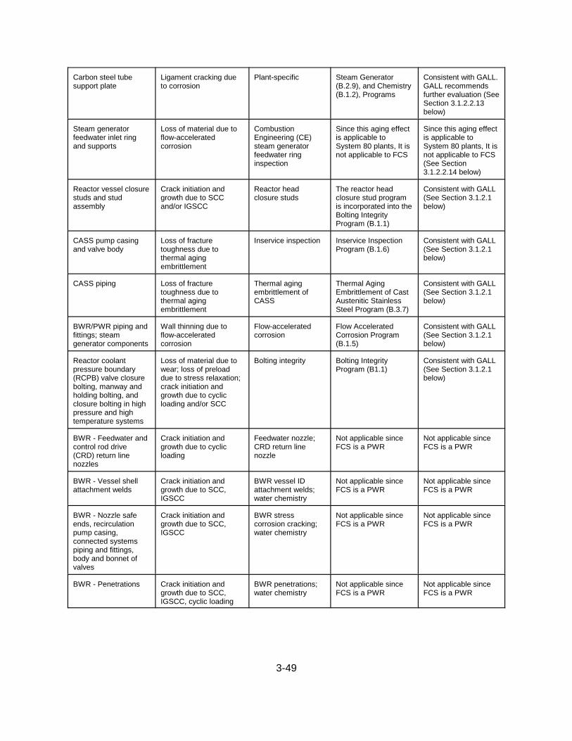
3-49
Carbon steel tubesupport plate
Ligament cracking dueto corrosion
Plant-specific Steam Generator(B.2.9), and Chemistry(B.1.2), Programs
Consistent with GALL.GALL recommendsfurther evaluation (SeeSection 3.1.2.2.13below)
Steam generatorfeedwater inlet ringand supports
Loss of material due toflow-acceleratedcorrosion
CombustionEngineering (CE)steam generatorfeedwater ringinspection
Since this aging effectis applicable toSystem 80 plants, It isnot applicable to FCS
Since this aging effectis applicable toSystem 80 plants, It isnot applicable to FCS(See Section3.1.2.2.14 below)
Reactor vessel closurestuds and studassembly
Crack initiation andgrowth due to SCCand/or IGSCC
Reactor headclosure studs
The reactor headclosure stud programis incorporated into theBolting IntegrityProgram (B.1.1)
Consistent with GALL(See Section 3.1.2.1below)
CASS pump casingand valve body
Loss of fracturetoughness due tothermal agingembrittlement
Inservice inspection Inservice InspectionProgram (B.1.6)
Consistent with GALL(See Section 3.1.2.1below)
CASS piping Loss of fracturetoughness due tothermal agingembrittlement
Thermal agingembrittlement ofCASS
Thermal AgingEmbrittlement of CastAustenitic StainlessSteel Program (B.3.7)
Consistent with GALL(See Section 3.1.2.1below)
BWR/PWR piping andfittings; steamgenerator components
Wall thinning due toflow-acceleratedcorrosion
Flow-acceleratedcorrosion
Flow AcceleratedCorrosion Program(B.1.5)
Consistent with GALL(See Section 3.1.2.1below)
Reactor coolantpressure boundary(RCPB) valve closurebolting, manway andholding bolting, andclosure bolting in highpressure and hightemperature systems
Loss of material due towear; loss of preloaddue to stress relaxation;crack initiation andgrowth due to cyclicloading and/or SCC
Bolting integrity Bolting IntegrityProgram (B1.1)
Consistent with GALL(See Section 3.1.2.1below)
BWR - Feedwater andcontrol rod drive(CRD) return linenozzles
Crack initiation andgrowth due to cyclicloading
Feedwater nozzle;CRD return linenozzle
Not applicable sinceFCS is a PWR
Not applicable sinceFCS is a PWR
BWR - Vessel shellattachment welds
Crack initiation andgrowth due to SCC,IGSCC
BWR vessel IDattachment welds;water chemistry
Not applicable sinceFCS is a PWR
Not applicable sinceFCS is a PWR
BWR - Nozzle safeends, recirculationpump casing,connected systemspiping and fittings,body and bonnet ofvalves
Crack initiation andgrowth due to SCC,IGSCC
BWR stresscorrosion cracking;water chemistry
Not applicable sinceFCS is a PWR
Not applicable sinceFCS is a PWR
BWR - Penetrations Crack initiation andgrowth due to SCC,IGSCC, cyclic loading
BWR penetrations;water chemistry
Not applicable sinceFCS is a PWR
Not applicable sinceFCS is a PWR

3-50
BWR - Core shroudand core plate,support structure, topguide, core spray linesand spargers, jetpump assemblies,control rod drivehousing, nuclearinstrumentation guidetubes
Crack initiation andgrowth due to SCC,IGSCC, IASCC
BWR vesselinternals; waterchemistry
Not applicable sinceFCS is a PWR
Not applicable sinceFCS is a PWR
BWR - Core shroudand core plate accesshole cover (weldedand mechanicalcovers)
Crack initiation andgrowth due to SCC,IGSCC, IASCC
ASME Section XIinservice inspection;water chemistry
Not applicable sinceFCS is a PWR
Not applicable sinceFCS is a PWR
BWR - Jet pumpassembly castings;orificed fuel support
Loss of fracturetoughness due tothermal aging andneutron embrittlement
Thermal aging andneutron irradiationembrittlement
Not applicable sinceFCS is a PWR
Not applicable sinceFCS is a PWR
BWR - Unclad tophead and nozzles
Loss of material due togeneral, pitting, andcrevice corrosion
Inservice inspection;water chemistry
Not applicable sinceFCS is a PWR
Not applicable sinceFCS is a PWR
CRD nozzle Crack initiation andgrowth due to PWSCC
Ni-alloy nozzles andpenetrations; waterchemistry
Chemistry (B.1.2) andAlloy 600 (B.3.1)Programs
Consistent with GALL(See Section 3.1.2.1below)
Reactor vesselnozzles safe ends andCRD housing; reactorcoolant systemcomponents (exceptCASS and bolting)
Crack initiation andgrowth due to cyclicloading, and/or SCC andPWSCC
Inservice inspection;water chemistry
Inservice Inspection(B.1.6) and Chemistry(B.1.2) Programs
Consistent with GALL(See Section 3.1.2.1.1for CRD housings andSection 3.1.2.1 below)
Reactor vesselinternals CASScomponents
Loss of fracturetoughness due tothermal aging, neutronirradiationembrittlement, and voidswelling
Thermal aging andneutron irradiationembrittlement
Reactor VesselInternals InspectionProgram (B.2.8)
Consistent with GALL(See Section 3.1.2.1below)
External surfaces ofcarbon steelcomponents in reactorcoolant systempressure boundary
Loss of material due toboric acid corrosion
Boric acid corrosion Boric Acid CorrosionPrevention Program(B.2.1)
Consistent with GALL(See Section 3.1.2.1below)
Steam generatorsecondary manwaysand handholds (CS)
Loss of material due toerosion
Inservice inspection Not applicable to FCS Not applicable to FCSbecause GALLindicates this item isapplicable to B&Wsteam generators
Reactor internals,reactor vessel closurestuds, and coresupport pads
Loss of material due towear
Inservice Inspection Inservice InspectionProgram (B.1.6)
Consistent with GALL(See Section 3.1.2.1below)

3-51
Pressurizer integralsupport
Crack initiation andgrowth due to cyclicloading
Inservice Inspection Not applicable to FCS Not applicable to FCS(See Section 3.1.2.1.2below)
Upper and lowerinternal assembly(Westinghouse)
Loss of preload due tostress relaxation
Inservice Inspection;loose part and/orneutron noisemonitoring
Not applicable sinceFCS is a CE plant
Not applicable sinceFCS is a CE plant
Reactor vesselinternals in fuel zoneregion (exceptWestinghouse andBabcock & Wilcox[B&W] baffle bolts)
Loss of fracturetoughness due to neutron irradiationembrittlement, and voidswelling
PWR vesselinternals; waterchemistry
Chemistry (B.1.2) andReactor VesselInternals Inspection(B.2.8)
Consistent with GALL(See Section 3.1.2.1below)
Steam generatorupper and lowerheads; tubesheets;primary nozzles andsafe ends
Crack initiation andgrowth due to SCC,PWSCC, IASCC
Inservice inspection;water chemistry
Inservice Inspection(B.1.6) and Chemistry(B.1.2) Programs
Consistent with GALL(See Section 3.1.2.1below)
Vessel internals(except Westinghouseand B&W baffleformer bolts)
Crack initiation andgrowth due to SCC andIASCC
PWR vesselinternals; waterchemistry
Chemistry (B.1.2) andReactor VesselInternals Inspection(B.2.8)
Consistent with GALL(See Section 3.1.2.1below)
Reactor internals(B&W screws andbolts)
Loss of preload due tostress relaxation
Inservice inspection;loose part monitoring
Not applicable sinceFCS is a CE plant
Not applicable sinceFCS is a CE plant
Reactor vessel closurestuds and studassembly
Loss of material due towear
Reactor headclosure studs
The reactor headclosure stud programis incorporated into theBolting IntegrityProgram (B.1.1)
Consistent with GALL(See Section 3.1.2.1below)
Reactor internals(Westinghouse upperand lower internalassemblies; CE boltsand tie rods)
Loss of preload due tostress relaxation
Inservice inspection;loose part monitoring
Inservice InspectionProgram (B.1.6)
Since it does not creditloose part monitoring,it is not consistent withGALL (See Section3.1.2.1.3 below)
The staff’s review of the reactor systems group for the FCS LRA is contained within foursections of this SER. Section 3.1.2.1 is the staff review of components in the reactor systemsthat the applicant indicates are consistent with GALL and do not require further evaluation. Section 3.1.2.2 is the staff review of components in the reactor systems that the applicantindicates are consistent with GALL and GALL recommends further evaluation. Section 3.1.2.3is the staff evaluation of aging management programs that are specific to the reactor systems. Section 3.1.2.4 contains an evaluation of the adequacy of aging management for componentsin each system in the reactor systems group and includes an evaluation of components in thereactor systems that the applicant indicates are not in GALL. This section is divided into threesubsections, reactor vessel internals, reactor coolant system, and reactor vessel. These arethe three systems that the applicant has identified as within the reactor systems group.

3-52
3.1.2.1 Aging Management Evaluations in the GALL Report That Are Relied on forLicense Renewal, Which Do Not Require Further Evaluation
For component groups evaluated in GALL for which the applicant has claimed consistency withGALL, and for which GALL does not recommend further evaluation, the staff sampledcomponents in these groups during the AMR inspection to determine whether the plant-specificcomponents contained in these GALL component groups were bounded by the GALLevaluation. The staff also sampled component groups during the AMR inspection to determinewhether the applicant had properly identified those component groups in GALL that were notapplicable to its plant. The results of the staff’s AMR inspection can be found in InspectionReport 50-285/03-07, dated March 20, 2003.
On the basis of its review of the inspection results, the staff finds that the applicant’s claim ofconsistency with GALL is acceptable, and that it is acceptable for the applicant to reference theinformation in the GALL Report for reactor system components. Therefore, on this basis, thestaff concludes that the applicant has demonstrated that the components for which theapplicant claimed consistency with GALL will be adequately managed so that the intendedfunction(s) will be maintained consistent with the current licensing basis for the period ofextended operation, as required by 10 CFR 54.21(a)(3).
3.1.2.1.1 Cracking of Control Rod Drive Housings
Programs identified in the GALL Report are generic programs. When components experienceunusual aging effects, the programs identified in the GALL Report may not be applicable. Control rod drive (CRD) housings (LRA Table 3.1-1, row 3.1.1.25), which are fabricated fromstainless steel, are identified as being susceptible to SCC and primary water stress corrosioncracking (PWSCC) with aging management provided by the ISI (B.1.6) and chemistry (B.1.2)programs. Cracking has been reported on CRD housings at FCS (January 25, 2002, letter fromOPPD) and Palisades (Nuclear Management Company letters to the NRC dated August 20,2001, and March 14, 2002 ). The Palisades and FCS CRD housings have similar designs.
Because this operating experience was not considered in the development of the LRA, the staffrequested the applicant to consider whether the proposed ISI and chemistry programs would beadequate for managing the aging effect of cracking of the control element drive mechanism(CEDM) housings at FCS. In response to RAI 3.1.1-4, the applicant indicated that in 1999, itbegan a proactive approach to dealing with the CRD housing cracking phenomenon byestablishing a CEDM Material Reliability Management Plan to monitor the CEDMs on anoutage-by-outage basis through the performance of eddy current testing of the CRDs. Detailsof the OPPD approach are contained in a letter from OPPD (R. L. Phelps) to NRC (DocumentControl Desk), dated January 25, 2002, "Fort Calhoun Station (FCS) Discussion of ControlElement Drive Mechanism (CEDM) Housing Reliability" (LIC-02-0007), and in a letter fromOPPD (R. L. Phelps) to NRC (Document Control Desk), dated October 15, 2001, "Fort CalhounStation (FCS) CEDM Housing Reliability Management" (LIC-01-0095).
The applicant considers this to be a CLB issue, with the resolution to be incorporated into theappropriate AMPs. The applicant indicates that it will continue to be involved inindustry/regulatory activities relative to this issue, and will apply recommended or mandatedactivities to the maintenance of the FCS CEDM housings as applicable. By letter datedFebruary 20, 2003, the staff issued POI-8(f) requesting the applicant to include a description of

3-53
the program to manage CEDM housings in the USAR Supplement. By letter dated March 14,2003, the applicant committed to apply recommended or mandated activities resulting from theCRD Material Reliability Management Plan with regard to management of CEDM housings. The applicant’s commitment to apply recommended or mandated activities resulting from theCRD Material Reliability Management Plan ensures that CEDM housings will receive adequateaging management during the license renewal term. The applicant committed to submit arevised AMP and associated USAR Supplement prior to the period of extended operation toensure that the revised AMP and USAR Supplement are adequate to manage the aging of theCEDM housings. POI-8(f) is resolved.
The staff reviewed the USAR Supplement for the ISI program and finds that, based on theapplicant’s commitments described above, the USAR provides an adequate summarydescription of the AMP to satisfy 10 CFR 54.21(d).
On the basis of its review, the staff finds that, based on the applicant’s commitments describedabove, the applicant has adequately evaluated the management of cracking in CRD housings.
3.1.2.1.2 Crack Initiation and Growth Due to Cyclic Loading of Pressurizer IntegralSupport
In response to RAI 3.1.2-6, the applicant indicated that this aging effect is not applicable for theFCS pressurizer integral supports because the terminology does not correspond to that usedfor FCS. However, in the response to this RAI, the applicant indicated that the agingmanagement of the support skirt should have been included, and now includes cracking for thelow alloy steel welds between the two low-alloy steel sections of the support skirt and betweenthe support skirt and the low alloy steel pressurizer. The FCS ISI program inspects thesewelds. FCS is, therefore, consistent with GALL Report line items IV.C2.5-v (the only differencebeing that the GALL Report includes materials of carbon steel or stainless steel while the FCSskirt is low-alloy steel). Since the aging effects and aging management program are consistentwith GALL, the AMR is acceptable.
The staff also reviewed the USAR Supplement for this aging management program and findsthat it provides an adequate summary description of the program, as required by 10 CFR54.21(d).
On the basis of its review, the staff finds that the applicant has adequately evaluated themanagement of crack initiation and growth due to cyclic loading of the pressurizer integralsupport.
3.1.2.1.3 Loss of Preload Due to Stress Relaxation of CE Bolts and Tie Rods in ReactorInternals
The applicant indicates that its program is not consistent with GALL because it does not creditloose parts monitoring. The applicant’s AMP for managing loss of preload due to stressrelaxation of CE bolts and tie rods in reactor internals is the ISI program. The staff considersthe ISI program adequate for loss of preload due to stress relaxation of CE bolts and tie rodsbecause the program has been successful during the current term and should be successfulduring the license renewal period. The applicant discusses the adequacy of this program inresponse to RAI 3.1.3-1 and additional discussion of this issue is contained in SER Section
3-54
3.1.2.3.2, in which the staff evaluates the reactor vessel internals inspection (RVII) AMP. In itsevaluation of this AMP, the staff reviewed CE reports on baffle former bolting and controlelement assembly (CEA) shroud bolts, and concluded that augmented examination of bolting inFCS reactor vessel internals is not necessary.
The staff reviewed the USAR Supplement for the ISI program and concludes that it provides anadequate summary description of the program and activities credited for managing loss ofpreload due to stress relaxation of CE bolts and tie rods in reactor internals to satisfy 10 CFR54.21(d).
On the basis of its review, the staff finds that, the applicant has adequately evaluated themanagement of loss of preload due to stress relaxation of CE bolts and tie rods in reactorinternals.
3.1.2.1.4 Conclusions
On the basis of its review of the inspection results the staff finds that the applicant’s claim ofconsistency with GALL is acceptable, and that it is acceptable for the applicant to reference theinformation in the GALL Report for reactor system components. Therefore, on this basis, thestaff concludes that, for those components that are managed consistent with the GALL Report,the applicant has demonstrated that the effects of aging will be adequately managed so that theintended function(s) will be maintained consistent with the CLB for the period of extendedoperation, as required by 10 CFR 54.21(a)(3).
The staff also reviewed the USAR Supplement for the ISI program, including the applicant’scommitments discussed above, and concludes that the supplement provides an adequatesummary description of the programs and activities credited for managing the effects of agingfor the reactor system components, as required by 10 CFR 54.21(d).
3.1.2.2 Aging Management Evaluations in the GALL Report That Are Relied on forLicense Renewal, For Which GALL Recommends Further Evaluation
For component groups evaluated in GALL for which the applicant has claimed consistency withGALL, and for which GALL recommends further evaluation, the staff reviewed the applicant’sevaluation to determine whether it adequately addressed the issues for which GALLrecommended further evaluation. In addition, the staff sampled components in these groupsduring the AMR inspection to determine whether the plant-specific components contained in these GALL component groups were bounded by the GALL evaluation. The results of thestaff’s AMR inspection can be found in Inspection Report 50-285/03-07, dated March 20, 2003.
The GALL Report indicates that further evaluation should be performed for the aging effectsdescribed in the following sections:
3.1.2.2.1 Cumulative Fatigue Damage
As stated in the SRP-LR, fatigue is a time-limited aging analysis (TLAA) as defined in 10 CFR54.3. TLAAs are required to be evaluated in accordance with 10 CFR 54.21(c)(1). The staffreviewed the evaluation of this TLAA in Section 4.3 of this SER, following the guidance inSection 4.3 of the SRP-LR.

3-55
On the basis of the staff’s review of LRA Section 4.3, the staff concludes that the componentsin the reactor systems subject to fatigue will be adequately managed during the period ofextended operation.
3.1.2.2.2 Loss of Material Due to Pitting and Crevice Corrosion
As stated in the SRP-LR, loss of material due to pitting and crevice corrosion could occur in thePWR steam generator shell assembly. The existing program relies on control of chemistry tomitigate corrosion and ISI to detect loss of material. The extent and schedule of the existingsteam generator inspections are designed to ensure that flaws cannot attain a depth sufficientto threaten the integrity of the welds. However, according to NRC Information Notice (IN) 90-04, “Cracking of the Upper Shell-to-Transition Cone Girth Welds in Steam Generators,” datedJanuary 26, 1990, if pitting and crevice corrosion of the shell exists, the program may not besufficient to detect pitting and corrosion. The GALL Report recommends augmented inspectionto manage this aging effect. The staff review verifies that the applicant has proposed aprogram that will manage loss of material due to pitting and crevice corrosion by providingenhanced inspection and supplemental methods to detect loss of material and ensure that thecomponent intended function will be maintained during the period of extended operation.
In response to RAI 3.1.1-1, the applicant indicates that the pitting and crevice corrosiondiscussed in IN 90-04 is applicable to Westinghouse Model 44 and Model 51 vertical,recirculation, U-tube steam generators with feedwater ring design. FCS has CombustionEngineering steam generators. Based on an evaluation from CE, the applicant concluded thatthe shell-to-cone girth welds at FCS will not be susceptible to cracking similar to that identifiedin IN 90-04.
The applicant proposed the ISI (B.1.6), chemistry (B.1.2), and steam generator (B.2.9)programs to manage loss of material due to pitting and crevice corrosion in the steam generatorshell assembly. The ISI program is reviewed in SER Section 3.0.3.5. The chemistry program isreviewed in SER Section 3.0.3.2. The steam generator program is reviewed in SER Section3.1.2.3.3. In addition, in response to RAI B.2.9-2, the applicant indicates that the secondaryshell, secondary handholds, secondary head, secondary manway, and transition cone arevisually inspected for loss of material (general, pitting, and crevice corrosion) to ensurepressure boundary integrity. This RAI response is discussed in greater detail in SER Section3.1.2.3.3.2.2.
The staff reviewed the USAR Supplement for the AMPs and concludes that they provideadequate summary descriptions of the programs and activities credited for managing theeffects of aging for the reactor system components for which the applicant claimed consistencywith GALL, as required by 10 CFR 54.21(d).
On the basis of its review, the staff finds that the applicant has adequately evaluated themanagement of loss of material due to pitting and crevice corrosion, as recommended in theGALL Report.
3.1.2.2.3 Loss of Fracture Toughness Due to Neutron Irradiation Embrittlement
As stated in the SRP-LR, certain aspects of neutron irradiation embrittlement are TLAAs, asdefined in 10 CFR 54.3. TLAAs are required to be evaluated in accordance with

3-56
10 CFR 54.21(c)(1). The staff reviewed the evaluation of this TLAA separately using theguidance in Section 4.2 of the SRP-LR. The results of the staff’s review can be found inSection 4.2 of this SER.
Loss of fracture toughness due to neutron irradiation embrittlement could occur in the reactorvessel. A reactor vessel materials surveillance program monitors neutron irradiationembrittlement of the reactor vessel. Reactor vessel surveillance programs are plant-specific,depending on matters such as the composition of limiting materials, availability of surveillancecapsules, and projected fluence levels. In accordance with 10 CFR Part 50, Appendix H, anapplicant is required to submit its proposed withdrawal schedule for approval prior toimplementation. Thus, the GALL Report recommends further evaluation of the reactor vesselmaterials surveillance program for the period of extended operation.
The applicant’s reactor vessel material surveillance program is documented in the reactorvessel integrity program (RVIP) (B.1.7), and Section 4.2 of the program basis document forRVIP. The RVIP is reviewed in SER section 3.1.2.3.1. The surveillance capsule withdrawalschedule was submitted for staff review in a letter from OPPD dated November 8, 2001. Thepurpose of the submittal was to modify the surveillance capsule withdrawal schedule to reflectthe renewal license period of 60 years. In a letter dated May 2, 2002, the staff indicated thatthe revised withdrawal schedule is acceptable for the renewal period of 60 years.
The staff reviewed the USAR Supplement for the RVIP AMP and concludes that it provides anadequate summary description of the programs and activities credited for managing the effectsof aging for the reactor system components for which the applicant claimed consistency withGALL, as required by 10 CFR 54.21(d).
On the basis of its review, the staff finds that the applicant has adequately evaluated themanagement of the loss of fracture toughness due to neutron irradiation embrittlement forcomponents in the reactor systems, as recommended in the GALL Report.
3.1.2.2.4 Crack Initiation and Growth Due to Thermal and Mechanical Loading or StressCorrosion Cracking
As stated in the SRP-LR, crack initiation and growth due to thermal and mechanical loading orSCC (including intergranular stress corrosion cracking (IGSCC)) could occur in the small-borereactor coolant system and connected system piping less than nominal pipe size (NPS) of 4inches. The existing program relies on the ASME Section XI ISI and on control of waterchemistry to mitigate SCC. The GALL Report recommends that a plant-specific destructiveexamination or a non-destructive evaluation (NDE) that permits inspection of the insidesurfaces of the piping be conducted to ensure that cracking has not occurred and thecomponent intended function will be maintained during the period of extended operation. TheAMPs should be augmented by verifying that service-induced weld cracking is not occurring inthe small-bore piping less than NPS 4 inches, including pipe, fittings, and branch connections. A one-time inspection of a sample of locations is an acceptable method to ensure that the agingeffect is not occurring and that the component’s intended function will be maintained during theperiod of extended operation. GALL Chapter XI.M32, "One-Time Inspection," contains anacceptable verification method.

3-57
The GALL Report recommends that the inspection include a representative sample of thesystem population, and, where practical and prudent, focus on the bounding or leadcomponents most susceptible to aging due to time in service, severity of operating conditions,and lowest design margin. For small-bore piping, actual inspection locations should be basedon physical accessibility, exposure levels, NDE techniques, and locations identified in IN 97-46,“Unisolable Crack in High-Pressure Injection Piping.” Combinations of NDE, including visual,ultrasonic, and surface techniques, are performed by qualified personnel following proceduresconsistent with the ASME Code and 10 CFR 50, Appendix B. For small-bore piping less thanNPS 4 inches, including pipe, fittings, and branch connections, a plant-specific destructiveexamination or NDE that permits inspection of the inside surfaces of the piping should beconducted to ensure that cracking has not occurred. Followup of unacceptable inspectionfindings should include expansion of the inspection sample size and locations. The inspectionand test techniques prescribed by the program should verify any aging effects because thesetechniques, used by qualified personnel, have been proven effective and consistent with staffexpectations. The staff’s review confirms that the program includes measures to verify thatunacceptable degradation is not occurring, thereby validating the effectiveness of existingprograms, or confirming that there is no need to manage aging-related degradation for theperiod of extended operation. If an applicant proposes a one-time inspection of selectcomponents and susceptible locations to ensure that corrosion is not occurring, the reviewerverifies that the proposed inspection will be performed using techniques similar to ASME Codeand American Society for Testing and Materials (ASTM) standards, including visual, ultrasonic,and surface techniques, to ensure that the component’s intended function will be maintainedduring the period of extended operation.
The GALL Report recommends that a plant-specific AMP be evaluated for the management ofcrack initiation and growth due to thermal and mechanical loading or SCC (including IGSCC) ina boiling-water reactor (BWR) reactor vessel flange leak detection line and BWR jet pumpsensing line. Since reactor vessel flange leak detection lines are also utilized in PWRs, thisissue is applicable to PWRs. The staff reviews the applicant’s proposed program on acase-by-case basis to ensure that an adequate program will be in place for the management ofthese aging effects. Acceptance criteria are described in BTP RLSB-1 (Appendix A.1 of theSRP).
The applicant has proposed the ISI (B.1.6), chemistry (B.1.2), and one-time inspection (B.3.5)programs to manage cracking of the small-bore RCS and connected system piping. The ISIprogram is reviewed in SER Section 3.0.3.5. The chemistry program is reviewed in SERsection 3.0.3.2. The one-time inspection program is reviewed in SER Section 3.0.3.13. TheISI program is consistent with XI.M1, “ASME Section XI Inservice Inspection, Subsections IWB,IWC, and IWD,” as identified in the GALL Report. ASME Code Section XI, Subsection IWB,requires surface and VT-2 visual examination. However, these examination methods will not beable to detect a crack initiating from the inside surface that is not through-wall. In order todetect a crack initiating from the inside surface that is not through-wall, a volumetricexamination is required.
The FCS chemistry program is consistent with XI.M2, “Water Chemistry,” as identified in theGALL Report. This program will mitigate damage caused by stress corrosion through periodicmonitoring and control of known detrimental contaminants. The FCS one-time inspectionprogram will be consistent with XI.M32, “One-Time Inspections,” as identified in the GALLReport prior to the period of extended operation. This program specifies that the inside surface

3-58
of piping be examined by either performing destructive examination or NDE. The NDE mustpermit inspection of the inside surface of the piping. NDE using volumetric examinationmethods can be performed from the outside and would be able to detect cracking initiating fromthe inside surface. During its inspection and audit conducted from January 6-10, 2003, andfrom January 20-23, 2003, the staff confirmed that the applicant’s one-time inspection programwill include volumetric examination and will inspect locations that are susceptible to SCC orthermal cycling. The results of the staff’s inspection and audit are documented in AMRInspection Report 50-285/03-07, dated March 20, 2003, and audit report dated April 9, 2003. Additional discussion of the one-time inspection program is contained in Section 3.0.3.13 of thisSER.
Leakage detection lines, or closure head vent lines, have been included within the scope oflicense renewal and are addressed in LRA Table 2.3.1.3-1 under the component type “Pipes &Fittings, CEDM Housings.” The applicable components are linked to AMR results Items3.1.1.01, 3.1.1.06, and 3.1.1.24. Item A2.1.4 in Section IV of the GALL Report indicates vesselflange leak detection lines require further plant-specific evaluation. Since this line functions asa pressure boundary for the vessel flange, by letter dated February 20, 2003, the staff issuedPOI-8(a), requesting the applicant to address the plant-specific review in item A2.1.4 in SectionIV of The GALL Report. In addition, the staff asked the applicant to identify the materials usedin the leakage detection line, the method of pressurizing the lines, and the inspection methodsthat are used to detect crack initiation and growth due to SCC that initiates on the insidesurface. By letter dated March 14, 2003, the applicant addressed this POI by stating that AMRItem 3.1.1.06 is equivalent to GALL Report Item IV.A2.1.4. AMR Item 3.1.1.06 specifies indiscussion item 3 that the lines are fabricated from stainless steel. Discussion item 2 specifiesthat the chemistry, ISI, and one-time inspection programs are to be used to manage the agingof these lines. The one-time inspection program will be used to verify that weld cracking is notoccurring. This is consistent with the GALL Report (IV.C1.1.13, IV.C2.1.5, and IV.C2.2.8). Theapplicant is treating these lines in the same manner as other small-bore RCS lines.
On the basis of its review of the information provided in the POI response, the staff finds thatthe applicant’s response, including its commitment to use the one-time inspection program toconfirm that weld cracking is not occurring, is adequate to ensure that the reactor vessel flangeleakage detection lines will be adequately managed during the period of extended operation. POI-8(a) is resolved.
The staff reviewed the USAR Supplements for the AMPs and concludes that they provideadequate summary descriptions of the programs and activities credited for managing theeffects of aging for the reactor system components for which the applicant claimed consistencywith GALL, as required by 10 CFR 54.21(d).
On the basis of its review, the staff finds that the applicant has adequately evaluated themanagement of crack initiation and growth due to thermal and mechanical loading or stresscorrosion cracking for small-bore piping and reactor vessel flange leak detection lines in thereactor systems, as recommended in the GALL Report.
3.1.2.2.5 Crack Growth Due to Cyclic Loading
As stated in the SRP-LR, crack growth due to cyclic loading could occur in the reactor vesselshell and RCS piping and fittings. Growth of intergranular separations (underclad cracks) in

3-59
low-alloy or carbon steel heat-affected zones under austenitic stainless steel cladding is a TLAAto be evaluated for the period of extended operation for all the SA 508, Class 2 forgings wherethe cladding was deposited with a high heat input welding process. The methodology forevaluating the underclad flaw should be consistent with the current, well-established flawevaluation procedure and criterion in the ASME Section XI Code. Section 4.7, “Other Plant-Specific Time-Limited Aging Analysis,” of the SRP-LR provides generic guidance for meetingthe requirements of 10 CFR 54.21(c). The GALL Report recommends further evaluation ofprograms to manage crack growth due to cyclic loading in the reactor vessel shell and RCSpiping and fittings. The GALL Report states that this aging effect is only applicable for thereactor vessel shell if it is made of SA 508, Class 2 forgings and is exposed to a neutronfluence greater than 1017 n/cm2. The applicant indicates that this aging effect is not applicableto FCS.
In response to RAI 3.1.1-2, the applicant indicates that the only reactor vessel componentsfabricated of SA 508, Class 2 steel and clad with a stainless steel or a nickel-based alloy weldoverlay, are the reactor vessel flange, closure head flange, and the primary coolant nozzles,nozzle extensions, and nozzle safe ends. A recent Westinghouse analysis performed for FCSindicates the flanges and nozzles will not experience a fluence greater than 1017 n/cm2 by theend of the period of extended operation. Based on its experience with neutron flux in regionsoutside the beltline, the staff agrees that the neutron fluence at the flange and nozzles will beless than 1017 n/cm2. In addition, the applicant indicates that Westinghouse/CE indicated to theapplicant that there have been no cases of underclad cracking of any clad CE reactor vesselsubcomponents. Based on this information, the staff concludes that this aging effect does notneed to be managed during the period of extended operation.
On the basis of its review, the staff finds that the applicant has adequately evaluated themanagement of crack growth due to cyclic loading for components in the reactor systems, asrecommended in the GALL Report.
3.1.2.2.6 Changes in Dimension Due to Void Swelling (PWR)
As stated in the SRP-LR, changes in dimension due to void swelling could occur in reactorinternal components. The GALL Report recommends further evaluation to ensure that thisaging effect is adequately managed. The reactor vessel internals receive a visual inspection(VT-3) according to Category B-N-3 of Subsection IWB of ASME Section XI. However, thisinspection is not sufficient to detect the effects of changes in dimension due to void swelling. Therefore, GALL recommends that a plant-specific AMP be evaluated. The applicant shouldprovide a plant-specific AMP or participate in industry programs to investigate aging effects anddetermine an appropriate AMP. Otherwise, the applicant should provide the basis forconcluding that void swelling is not an issue for the component. The staff verifies that theapplicant has either proposed a program to manage changes in dimension due to void swellingin the pressure vessel internal components, or provided the basis for concluding that voidswelling is not an issue.
The applicant has not indicated that void swelling is not an issue. The applicant has proposedto manage this aging effect by the RVII program (B.2.8). This program is reviewed in SERSection 3.1.2.3.2. The RVII program references GALL programs XI.M13, “Thermal Aging andNeutron Irradiation Embrittlement of Cast Austenitic Stainless Steel (CASS),” and XI.M16,“PWR Vessel Internals,” as identified in the GALL Report. These GALL sections identify

3-60
programs that are acceptable to the staff for managing void swelling. Since the applicant hasproposed a program to manage this aging effect, the applicant has provided the additionalinformation requested in the SRP-LR.
The staff reviewed the USAR Supplement for the RVII program and concludes that it providesan adequate summary description of the programs and activities credited for managing theeffects of aging for the reactor system components for which the applicant claimed consistencywith GALL, as required by 10 CFR 54.21(d).
On the basis of its review, the staff finds that the applicant has adequately evaluated themanagement of changes in dimension due to void swelling for reactor vessel internalscomponents, as recommended in the GALL Report.
3.1.2.2.7 Crack Initiation and Growth Due to Stress Corrosion Cracking or Primary WaterStress Corrosion Cracking
As stated in the SRP-LR, crack initiation and growth due to SCC and PWSCC could occur inPWR core support pads (or core guide lugs), instrument tubes (bottom head penetrations),pressurizer spray heads, and nozzles for the steam generator instruments and drains. TheGALL Report recommends further evaluation to ensure that these aging effects are adequatelymanaged. The GALL Report also recommends that a plant-specific AMP be evaluatedbecause existing programs may not be capable of mitigating or detecting crack initiation andgrowth due to SCC. Acceptance criteria are described in BTP RLSB-1 (Appendix A.1 of theSRP-LR). The staff reviewed the applicant’s proposed program to ensure that an adequateprogram will be in place for the management of these aging effects.
Crack initiation and growth due to SCC could occur in PWR CASS RCS piping and fittings andthe pressurizer surge line nozzle. The GALL Report recommends further evaluation of pipingthat do not meet either the reactor water chemistry guidelines of TR-105714, “PWR PrimaryWater Chemistry Guidelines-Revision 3,” November 1995, or material guidelines of NUREG-0313, Revision. 2, "Technical Report on Material Selection and Processing Guidelines for BWRCoolant Pressure Boundary Piping." Acceptance criteria are described in BTP RLSB-1(Appendix A.1 of the SRP-LR). The staff reviewed the applicant’s proposed program to ensurethat an adequate program will be in place for the management of these aging effects.
Crack initiation and growth due to PWSCC could occur in PWR pressurizer instrumentationpenetrations and heater sheaths and sleeves made of nickel alloys. The existing programrelies on the ASME Section XI ISI and on control of water chemistry to mitigate PWSCC. However, the existing program should be augmented to manage the effects of SCC on nickel-alloy components. The GALL Report recommends that the applicant provide a plant-specificAMP or participate in industry programs to determine an appropriate AMP for PWSCC of Alloy600 and Inconel 82/182 welds. Acceptance criteria are described in BTP RLSB-1 (AppendixA.1 of the SRP-LR). The staff reviewed the applicant’s proposed program to ensure that anadequate program will be in place for the management of these aging effects.
The applicant has proposed to manage crack initiation and growth due to SCC or PWSCC for core support pads, instrument tubes (bottom head penetrations), pressurizer spray heads andnozzles for the steam generator instruments and drains using the Alloy 600 program (B.3.1). This program is evaluated in SER Section 3.1.2.3.4. The Alloy 600 program references GALL

3-61
program XI.M11, “Nickel-Alloy Nozzles and Penetrations,” as identified in the GALL Report. This GALL section identifies programs that are acceptable to the staff for managing crackinitiation and growth due to SCC or PWSCC.
The applicant has proposed to manage crack initiation and growth due to SCC in CASS RCSpiping using the chemistry (B.1.2), ISI (B.1.6), and thermal embrittlement of CASS (B.3.7)programs. The ISI program is reviewed in SER Section 3.0.3.5. The chemistry program isreviewed in SER Section 3.0.3.2. The thermal embrittlement of CASS program is reviewed inSER Section 3.1.2.3.5. The FCS chemistry program is consistent with GALL program XI.M32,“Water Chemistry,” as identified in the GALL Report. This program will mitigate damagecaused by stress corrosion through periodic monitoring and control of known detrimentalcontaminants. GALL program XI.M2 indicates that the primary water chemistry program isbased on the EPRI guidelines in TR-105714. Since the proposed program is consistent withEPRI guidelines in TR-105714, the applicant has proposed an acceptable program to managethis aging effect and the applicant has provided the additional information requested in theSRP-LR.
The applicant has proposed to manage crack initiation and growth due to PWSCC inpressurizer instrumentation penetrations and heater sheaths and sleeves made of nickel-alloysby the Alloy 600 (B.3.1), chemistry (B.1.2), and ISI (B.1.6) programs. The ISI program isreviewed in SER Section 3.0.3.5. The chemistry program is reviewed in SER Section 3.0.3.2. The Alloy 600 program is reviewed in SER Section 3.1.2.3.4. The Alloy 600 programreferences GALL program XI.M11, “Nickel-Alloy Nozzles and Penetrations,” as identified in theGALL Report. This GALL section identifies programs that are acceptable to the staff formanaging crack Initiation and growth due to SCC or PWSCC.
The staff reviewed the USAR Supplement for the AMPs and concludes that they provideadequate summary descriptions of the programs and activities credited for managing theeffects of aging for the reactor system components for which the applicant claimed consistencywith GALL, as required by 10 CFR 54.21(d).
On the basis of its review, the staff finds that the applicant has adequately evaluated themanagement of crack initiation and growth due to SCC or PWSCC for components in thereactor systems, as recommended in the GALL Report.
3.1.2.2.8 Crack Initiation and Growth Due to Stress Corrosion Cracking or Irradiation-Assisted Stress Corrosion Cracking
As stated in the SRP-LR, crack initiation and growth could occur in baffle/former bolts due toSCC or irradiation-assisted stress corrosion cracking (IASCC) in Westinghouse and B&Wreactors. FCS is a CE reactor and therefore this issue does not apply.
On the basis of its review, the staff finds that the applicant has adequately evaluated themanagement of crack initiation and growth due to SCC or IASCC for baffle/former bolts, asrecommended in the GALL Report.

3-62
3.1.2.2.9 Loss of Preload Due to Stress Relaxation
As stated in the SRP-LR, loss of preload due to stress relaxation could occur in baffle/formerbolts in Westinghouse and B&W reactors. Loss of preload on baffle/former bolts is due toneutron irradiation and could occur in components that are susceptible to SCC or IASCC. Since baffle/former bolts in CE reactors are not susceptible to SCC or IASCC, they would notbe susceptible to loss of preload due to stress relaxation. FCS is a CE reactor and thereforethis issue does not apply.
On the basis of its review, the staff finds that the applicant has adequately evaluated themanagement of the loss of preload due to stress relaxation for components in the reactorsystems, as recommended in the GALL Report.
3.1.2.2.10 Loss of Section Thickness due to Erosion
As stated in the SRP-LR, loss of section thickness due to erosion could occur in steamgenerator feedwater impingement plates and supports. The GALL Report recommends furtherevaluation of a plant-specific AMP to ensure that this aging effect is adequately managed.Acceptance criteria are described in BTP RLSB-1 (Appendix A.1 of this SRP). The staffreviewed the applicant’s proposed program to ensure that an adequate program will be in placefor the management of this aging effect.
The applicant indicates that this aging effect is not applicable because FCS does not utilizeimpingement plates and supports for supplying feedwater to the steam generators. By letterdated February 20, 2003, the staff issued POI-8(b), requesting the applicant to clarify whetherFCS has steam generator feedwater impingement plates and supports. By letter dated March14, 2003, the applicant directed the staff to LRA AMR Item 3.1.1.14. On the basis of theapplicant’s response to POI-8(b), the staff finds that feedwater is supplied to steam generatorsthrough the steam generator feedwater feed ring. The steam generator feedwater feed ring issusceptible to cumulative fatigue and loss of material. Based on plant operating experience, itis not susceptible to loss of section thickness due to erosion. Since FCS does not utilizeimpingement plates and associated supports, and the steam generator feedwater feed ring isnot susceptible to loss of section thickness due to erosion, this aging effect is not applicable toFCS. POI-8(b) is resolved.
On the basis of its review, the staff finds that the applicant has adequately evaluated themanagement of the loss of section thickness due to erosion for components in the reactorsystems, as recommended in the GALL Report.
3.1.2.2.11 Crack Initiation and Growth Due to PWSCC, ODSCC, or Intergranular Attack, orLoss of Material Due to Wastage and Pitting Corrosion, or Loss of SectionThickness Due to Fretting and Wear, or Denting Due to Corrosion at CarbonSteel Tube Support Plate Intersections
As stated in the SRP-LR, crack initiation and growth due to PWSCC, outside diameter stresscorrosion cracking (ODSCC), or intergranular attack (IGA) or loss of material due to wastageand pitting corrosion or deformation due to corrosion could occur in Alloy 600 components ofthe steam generator (SG) tubes, repair sleeves, and plugs. The GALL Report recommendsfurther evaluation of (1) crack initiation and growth due to PWSCC, ODSCC, or IGA or (2) loss

3-63
of material due to wastage and pitting corrosion or (3) deformation due to corrosion in Alloy 600components of the SG tubes, repair sleeves, and plugs. All PWR licensees have committedvoluntarily to an SG degradation management program described in NEI 97-06, “SteamGenerator Program Guidelines.” The GALL Report recommends that an AMP based on therecommendations of staff-approved NEI 97-06 guidelines, or some other alternate regulatorybasis for SG degradation management, be developed to ensure that this aging effect isadequately managed. At present, the staff does not plan to endorse NEI 97-06 or detailedindustry guidelines referenced therein. The staff is working with the industry to revise planttechnical specifications to incorporate the essential elements of the industry’s NEI 97-06initiative as necessary to ensure tube integrity is maintained. This would requireimplementation of programs to ensure that performance criteria for tube structural and leakageintegrity are maintained, consistent with the plant design and licensing basis. NEI 97-06provides guidance on programmatic details for accomplishing this objective. These guidelinesapply to all degradation or damage mechanisms. However, these programmatic details wouldbe outside the scope of the technical specifications. As part of the NRC Reactor OversightProgram, NRC would monitor the effectiveness of these programs in terms of whether the goalsof these programs are being met, particularly whether the tube structural and leakage integrityperformance criteria are being maintained. The staff reviewed the applicant’s proposedprogram to ensure that an adequate program will be in place for the management of theseaging effects for the period of extended operation.
The applicant has proposed to manage (1) crack initiation and growth due to PWSCC, ODSCC,or intergranular attack, or (2) loss of material due to wastage and pitting corrosion, or (3) loss ofsection thickness due to fretting and wear, or (4) denting due to corrosion of carbon steel tubesupport plate intersections by the steam generator (B.2.9) and chemistry (B.1.2) programs. The chemistry program is reviewed in SER Section 3.0.3.2. The steam generator program(SGP) is reviewed in SER Section 3.1.2.3.3. These aging effects are discussed in greaterdetail in SER Section 3.1.2.3.3.2.4.
The staff reviewed the USAR Supplement for the AMPs and concludes that they provideadequate summary descriptions of the programs and activities credited for managing theeffects of aging for the reactor system components for which the applicant claimed consistencywith GALL, as required by 10 CFR 54.21(d).
On the basis of its review, the staff finds that the applicant has adequately evaluated themanagement of (1) crack initiation and growth due to PWSCC, ODSCC, or intergranular attack,or (2) loss of material due to wastage and pitting corrosion, or (3) loss of section thickness dueto fretting and wear, or (4) denting due to corrosion at carbon steel tube support plateintersections, as recommended in the GALL Report.
3.1.2.2.12 Loss of Section Thickness Due to Flow-Accelerated Corrosion
As stated in the SRP-LR, loss of section thickness due to FAC could occur in tube supportlattice bars made of carbon steel. The GALL Report recommends further evaluation of loss ofsection thickness due to flow-accelerated corrosion of the tube support lattice bars made ofcarbon steel. The GALL Report recommends a plant-specific AMP be evaluated and, on thebasis of the guidelines of NRC Generic Letter 97-06, an inspection program for SG internals bedeveloped to ensure that this aging effect is adequately managed. The staff reviewed theapplicant’s proposed program to ensure that an adequate program will be in place for the
3-64
management of these aging effects. Acceptance criteria are described in BTP RLSB-1(Appendix A.1 of the SRP-LR).
Loss of section thickness due to FAC in tube support lattice bars made of carbon steel ismanaged by the SGP (B.2.9). The applicant’s SGP is reviewed in SER Section 3.1.2.3.3. Thisaging effect is discussed in greater detail in SER Section 3.1.2.3.3.2.5.
The staff reviewed the USAR Supplement for the SG program and concludes that it provides anadequate summary description of the programs and activities credited for managing the effectsof aging for the reactor system components for which the applicant claimed consistency withGALL, as required by 10 CFR 54.21(d).
On the basis of its review, the staff finds that the applicant has adequately evaluated themanagement of the loss of section thickness due to FAC for components in the reactorsystems, as recommended in the GALL Report.
3.1.2.2.13 Ligament Cracking Due to Corrosion
As stated in the SRP-LR, ligament cracking due to corrosion could occur in the carbon steel SGtube support plate. The GALL Report recommends further evaluation of ligament cracking dueto corrosion in carbon steel components in the SG tube support plate. All PWR licensees havecommitted voluntarily to an SG degradation management program described in NEI 97-06. TheGALL Report recommends that an AMP based on the recommendations of staff-approved NEI97-06 guidelines, or some other alternate regulatory basis for SG degradation management, bedeveloped to ensure that this aging effect is adequately managed. At present, the staff doesnot plan to endorse NEI 97-06 or detailed industry guidelines referenced therein. The staff isworking with the industry to revise plant technical specifications to incorporate the essentialelements of the industry’s NEI 97-06 initiative as necessary to ensure tube integrity ismaintained. This would require implementation of programs to ensure that performance criteriafor tube structural and leakage integrity are maintained, consistent with the plant design andlicensing basis. NEI 97-06 provides guidance on programmatic details for accomplishing thisobjective. These guidelines apply to all degradation or damage mechanisms. However, theseprogrammatic details would be outside the scope of the technical specifications. As part of theNRC Reactor Oversight Program, NRC would monitor the effectiveness of these programs interms of whether the goals of these programs are being met particularly whether the tubestructural and leakage integrity performance criteria are being maintained. The staff reviewedthe applicant’s proposed program to ensure that an adequate program will be in place for themanagement of these aging effects.
Ligament cracking due to corrosion which could occur in the carbon steel steam generator tubesupport plate is managed by the SG (B.2.9) and chemistry (B.1.2) programs. The chemistryprogram is reviewed in SER Section 3.0.3.2. The SGP is reviewed in SER Section 3.1.2.3.3. The FCS chemistry program is consistent with GALL program XI.M2, “Water Chemistry,” asidentified in the GALL Report. This program will mitigate damage caused by stress corrosionthrough periodic monitoring and control of known detrimental contaminants. This aging effect isdiscussed in greater detail in SER Section 3.1.2.3.3.2.6.
The staff reviewed the USAR Supplement for the AMPs and concludes that they provideadequate summary descriptions of the programs and activities credited for managing the

3-65
effects of aging for the reactor system components for which the applicant claimed consistencywith GALL, as required by 10 CFR 54.21(d).
On the basis of its review, the staff finds that the applicant has adequately evaluated themanagement of ligament cracking due to corrosion for components in the reactor systems, asrecommended in the GALL Report.
3.1.2.2.14 Loss of Material Due to Flow-Accelerated Corrosion
As stated in the SRP-LR, loss of material due to FAC could occur in the feedwater inlet ring andsupports. The GALL Report recommends that a plant-specific AMP be evaluated to manageloss of material due to FAC in these components. As noted in IN 90-04, “Cracking of the UpperShell-to-Transition Cone Girth Welds in Steam Generators,” IN 91-19, "Steam GeneratorFeedwater Distribution Piping Damage," and licensee event report (LER) 50-362/90-05-01, thisform of degradation has been detected only in certain CE System 80 steam generators. TheGALL Report recommends that a plant-specific AMP be evaluated because existing programsmay not be capable of mitigating or detecting loss of material due to FAC. Acceptance criteriaare described in BTP RLSB-1 (Appendix A.1 of the SRP). The staff reviewed the applicant’sproposed program to ensure that an adequate program will be in place for the management ofthese aging effects. However, since this aging effect is applicable only to System 80 plants, itis not applicable to FCS.
On the basis of its review, the staff finds that the applicant has adequately evaluated themanagement of the loss of material due to FAC for components in the reactor systems, asrecommended in the GALL Report.
3.1.2.2.15 Conclusions
The staff has reviewed the applicant’s evaluation of the issues for which GALL recommendsfurther evaluation for components in the reactor systems. On the basis of its review, the staffconcludes that the applicant has provided sufficient information to demonstrate that the issuesfor which GALL recommends further evaluation have been adequately addressed, and that thesubject aging effects will be adequately managed for the period of extended operation, asrequired by 10 CFR 54.21(a)(3). In addition, the staff concludes that the applicant’s USARSupplements provide adequate descriptions of the programs credited with managing theseaging effects, as required by 10 CFR 54.21(d).
3.1.2.3 Aging Management Programs for Reactor Systems Components
In SER Sections 3.1.2.1 and 3.1.2.2, the staff determined that the applicant’s AMRs andassociated AMPs will adequately manage component aging in the reactor systems. The staffthen reviewed specific components in the reactor systems to ensure that they were properlyevaluated in the applicant’s AMR.
To perform its evaluation, the staff reviewed the components listed in LRA Tables 2.3.1.1-1through 2.3.1.3-1 to determine whether the applicant had properly identified the applicableAMRs and AMPs needed to adequately manage component aging effects. This portion of thestaff review involved identification of the aging effects for each component, ensuring that eachaging effect was evaluated using the appropriate AMR in Section 3, and that management of
3-66
the aging effect was captured in the appropriate AMP. The results of the staff’s review areprovided below.
The staff also reviewed the USAR Supplements for the AMPs credited with managing aging inreactor system components to determine whether the program description adequatelydescribes the program.
The applicant credits 12 AMPs to manage the aging effects associated with components in thereactor systems. Seven of the AMPs are credited for managing the aging of components inseveral system groups (common AMPs), while five AMPs are credited with managing agingonly for reactor system components. The staff’s evaluation of the common AMPs is provided inSection 3.0.3 of this SER. A list of the common AMPs follows.
• Bolting Integrity Program - SER Section 3.0.3.1• Chemistry Program - SER Section 3.0.3.2• Flow-Accelerated Corrosion Program - SER Section 3.0.3.4• Inservice Inspection Program - SER Section 3.0.3.5• Boric Acid Corrosion Prevention Program - SER Section 3.0.3.6• Fatigue Monitoring Program - SER Section 3.0.3.8• One-Time Inspection - SER Section 3.0.3.13
The staff’s evaluation of the five reactor system AMPs is provided below.
3.1.2.3.1 Reactor Vessel Integrity Program
3.1.2.3.1.1 Summary of Technical Information in the Application
The applicant’s reactor vessel integrity program (RVIP) is documented in Section B.1.7 of theLRA. The applicant states that the RVIP is consistent with GALL program XI.31, “ReactorVessel Surveillance,” as identified in the GALL Report, with the enhancement that the revised,optimized withdrawal and test schedule was submitted for review and approval per OPPD LetterLIC-01-0107 dated November 8, 2001. This AMP is credited for managing loss of fracturetoughness due to neutron irradiation embrittlement of the reactor vessel beltline shell andwelds.
3.1.2.3.1.2 Staff Evaluation
The staff reviewed the enhancement and its justification to determine whether the AMP, withthe enhancement, remains adequate to manage the aging effects for which it is credited. Thestaff also reviewed the USAR Supplement to determine whether it provides an adequatedescription of the revised program. The staff further reviewed the applicant’s evaluation todetermine whether it addressed the additional issues recommended in the GALL Report, andconfirmed that the AMP would adequately address these issues.
In LRA Section B.1.7, “Reactor Vessel Integrity Program,” the applicant described its AMP tomanage aging in the reactor vessel beltline shell and welds. The LRA stated that this AMP isconsistent with GALL AMP XI.31, with an enhancement that the revised, optimized withdrawaland test schedule was submitted for review and approval per OPPD Letter LIC-01-0107 datedNovember 8, 2001. For this AMP, GALL recommends further evaluation. The proposed

3-67
withdrawal schedule was reviewed and approved by the staff in a letter from S. Dembek (NRC)to R. T. Ridenoure (OPPD) dated May 2, 2002. In this letter, the staff found the revisedwithdrawal schedule acceptable for 60 years. In addition, the staff approved an integratedsurveillance program for FCS as described in CEN-636, Revision 2, in a safety evaluation datedJune 6, 2001. The use of the integrated surveillance program allows OPPD to utilize dataoriginating from the surveillance programs at Mihama 1, Palisades, and Diablo Canyon Unit 1,to monitor neutron irradiation embrittlement to the FCS reactor vessel beltline. The weldmaterials in Mihama 1, Palisades, and Diablo Canyon Unit 1 surveillance capsules containmaterial that is representative of the weld materials in the FCS beltline. The staff review thatwas documented in letters dated June 6, 2001, and May 2, 2002, satisfies the SRPrecommendation for further evaluation.
The applicant provided its USAR Supplement for the RVIP in Section A.2.19 of the LRA. Thestaff reviewed the USAR Supplement and finds that the summary description contains asufficient level of information to satisfy 10 CFR 54.21(d), and is acceptable.
3.1.2.3.1.3 Conclusion
On the basis of its review of the applicant’s program, the staff finds that those portions of theprogram for which the applicant claims consistency with GALL are consistent with GALL. Inaddition, the staff has reviewed the enhancements to the GALL program and finds that theapplicant’s program provides for adequate management of the aging effects for which theprogram is credited. The staff also reviewed the USAR Supplement for this AMP and finds thatit provides an adequate summary description of the program to satisfy 10 CFR 54.21(d).
Therefore, on the basis of its review, the staff concludes that the applicant has demonstratedthat the RVIP will effectively manage aging in the components for which this program iscredited so that the intended functions of the associated components and systems will bemaintained consistent with the CLB for the period of extended operation, as required by 10 CFR54.21(a)(3).
3.1.2.3.2 Reactor Vessel Internals Inspection Program
3.1.2.3.2.1 Summary of Technical Information in the Application
The applicant’s reactor vessel internals inspection (RVII) program is discussed in LRA SectionB.2.8, “Reactor Vessel Internals Inspection Program.” The applicant states that the program isconsistent with GALL programs XI.M13, “Thermal Aging and Neutron Irradiation Embrittlementof Cast Austenitic Stainless Steel (CASS),” and XI.M16, “PWR Vessel Internals,” with theexception that no augmented inspection of bolting is scheduled and the chemistry-relatedportions of the program are addressed in the FCS chemistry program. The tensile stresses onthe reactor vessel internals bolting are lower than the industry levels where cracking wasobserved as an aging effect. The applicant also states that fluence and stress analysesdiscussed in GALL programs XI.M13 and XI.M16 will be performed to identify critical locations. A fracture mechanics analysis for critical locations will be performed to determine flawacceptance criteria and resolution required to detect flaws. Appropriate inspection techniqueswill be based on these analyses. This AMP is credited for managing change of dimension dueto void swelling and crack initiation and growth due to SCC and IASCC in reactor vesselinternals.

3-68
3.1.2.3.2.2 Staff Evaluation
In LRA Section B.2.8, the applicant described its AMP to manage aging in reactor internals. The LRA stated that this AMP is consistent with GALL AMPs XI.M13 and XI.M16 with theexception that no augmented inspection of bolting is scheduled and the chemistry-relatedportions of the program are addressed in the FCS chemistry program. For these AMPs, GALLrecommends further evaluation. GALL XI. M13 indicates that an applicant can implement eithera supplemental examination of the affected component as a part of the 10-year ISI programduring license renewal, or a component-specific evaluation to determine the component’ssusceptibility to loss of fracture toughness. GALL XI.M16 further indicates that an applicant’sprogram should identify the most limiting component, develop appropriate inspectiontechniques, and implement the inspections during the license renewal term. Theserecommendations have been satisfied since the applicant indicates that fluence and stressanalyses discussed in GALL programs XI.M13 and XI.M16 will be performed to identify criticallocations. A fracture mechanics analysis for critical locations will be performed to determineflaw acceptance criteria and resolution required to detect flaws. Appropriate inspectiontechniques will be based on these analyses.
The staff confirmed the applicant’s claim of consistency during the AMR inspection. Furthermore, the staff reviewed the exceptions and their justification to determine whether theAMP, with the exceptions, remains adequate to manage the aging effects for which it iscredited. The staff also reviewed the USAR Supplement to determine whether it provides anadequate description of the revised program. The staff further reviewed the applicant’sevaluation to determine whether it addressed the additional issues recommended in the GALLReport and confirmed that the AMP would adequately address these issues.
For bolted components, GALL XI.M16 indicates that an augmented ISI is recommended todetect cracks between the bolt head and shank unless the applicant performs component-specific mechanical analyses to preclude cracking. In the “operating experiences” portion ofthe RVII program, the applicant provided an evaluation of the susceptibility of cracking in baffleformer bolts and CEA shroud bolts. The Combustion Engineering Owners Group (CEOG)provided an assessment of the cracking of the baffle former bolts reported in foreign PWRs,including the potential impact of the cracking on domestic CE plants. The results are in CEOGReport CE NPSD-1098 for CEOG Task 1011, “Evaluation of the Applicability of Baffle BoltCracking to Ft. Calhoun and Palisades Internals Bolts,” Final Report, Revision 0, April 1998. The most likely mechanism for the cracking of cold-worked 316 stainless steel baffle formerbolts in foreign plants is IASCC. There are only two CE-designed plants (FCS and Palisades)that use bolts to attach the core shroud panels (i.e., the baffle plates) to the former plates. Thereport indicates that these bolts in FCS are less susceptible to IASCC because (1) the materialused in these bolts is annealed 316 stainless steel, which is not cold-worked, (2) the bolt stressfrom preload, as a percentage of yield strength, is much less than the foreign PWRs thatcracked, (3) the differential pressure across the core shroud panels does not result in tensileloads on the panel (i.e., the baffle bolts) during normal operation, and (4) the core shroud paneldesign allows for some flexing of the former plate relative to the core barrel, thus reducing theload on the panel bolts. Since CE NPSD-1098 was issued, cracking has been discovered inPoint Beach baffle bolts. However, as with the foreign PWR experience, cracked bolts werehighly stressed during preload, tensile stresses were applied during operation because of theWestinghouse design, and the bolts were fabricated with cold-worked 316 stainless steel. Based on the difference in the design, materials, and preload between the Point Beach and the

3-69
foreign PWR that experienced baffle former bolt cracking, the FCS baffle former bolts are lesssusceptible to cracking and augmented inspection is not necessary.
SCC was identified in Babcock and Wilcox (B&W) lower thermal shield and lower core barrelbolts that were fabricated with Alloy A-286. Most of the failed bolts were highly stressed to at orabove the yield strength. Although there have been no failures of CEA shroud bolts in CE-designed reactor vessel internals, there is a concern that SCC may occur since these bolts arefabricated with Alloy A-286. CE provided an evaluation of the stress level for these bolts inCEN-282, “Investigation and Evaluation of A286 Bolt Applications in CE's NSSS,” September1984. This report indicates that the operating stress levels are just below 32 Ksi. The stressconcentration factor for the CEA shroud bolts is 2.06, leading to a local stress of approximately66 Ksi. Yield strength for A-286 is about 115 Ksi, so the stress is approximately 60 percent ofyield. Most of the failed B&W bolts had working stresses of approximately 65 Ksi and a localstress of 134 Ksi which is above the yield strength of the material. There were no failed boltswith working stresses of 35 Ksi. The conclusion of the report indicates a low probability forcracking of the CEA shroud bolts. Based on the difference in the operating stresses on theCEA shroud bolts and the failed B&W bolts, and the fact that there have been no failures ofCEA shroud bolts in CE-designed reactor vessel internals, the staff concludes that the CEAshroud bolts are less susceptible to SCC and augmented inspection is not necessary.
The applicant provided its USAR Supplement for the RVII program in Section A.2.20 of theLRA. The staff reviewed the USAR Supplement and finds that the summary descriptioncontains a sufficient level of information to satisfy 10 CFR 54.21(d), and is acceptable.
3.1.2.3.2.3 Conclusion
On the basis of its review and inspection of the applicant’s program, the staff finds that thoseportions of the program for which the applicant claims consistency with GALL are consistentwith GALL. In addition, the staff has reviewed the exceptions and enhancements to the GALLprogram and finds that the applicant’s program provides for adequate management of the agingeffects for which the program is credited. The staff also reviewed the USAR Supplement forthis AMP and finds that it provides an adequate summary description of the program to satisfy10 CFR 54.21(d).
Therefore, on the basis of its review, the staff concludes that the applicant has demonstratedthat the RVII program will effectively manage aging in the components for which this program iscredited so that the intended functions of the associated components and systems will bemaintained consistent with the CLB for the period of extended operation, as required by 10 CFR54.21(a)(3).
3.1.2.3.3 Steam Generator Program
3.1.2.3.3.1 Summary of Technical Information in the Application
The applicant’s steam generator program (SGP) is discussed in LRA Section B.2.9, “SteamGenerator Program.” The applicant states that the program is consistent with GALL programXI.M19, “Steam Generator Tube Integrity,” with the clarifications that the applicant has includedaging management activities to address plant-specific AMP requirements identified in Table3.1.1 of the LRA, and the enhancement that the applicant has added plant-specific components
3-70
beyond those discussed in GALL and identified in Table 3.1.2 of the LRA, for which the SGP isidentified as an AMP. The applicant also identified an enhancement which states that anannunciator response procedure for the loose parts monitor in the SG will be written.
This AMP is credited with managing aging in the SG shell assembly; SG tubes, repair sleeves,and plugs; tube support lattice bars made of carbon steel; carbon steel tube support plates; SGlower head and primary side tube sheet; secondary side of the tubesheet, SG feedwater, steamand instrument nozzles, and feedwater nozzle safe ends; SG steam nozzle safe end; and SGfeed ring.
The applicant stated that management of SG aging effects has evolved and improved over theyears based on industry experience. The applicant has adopted industry practices throughoutthe years and continues to do so. Past NRC inspections of this program cited sample plansand inspection evaluation as a strength. Only one noteworthy situation occurred at FCS. In1984, a tube with ODSCC in the U-bend region of the SG ruptured. Re-evaluation of the eddycurrent data from the previous inspection indicated that flaws were present and had beenmissed during the data analysis due to human error. This situation was corrected and long-term corrective actions were implemented to prevent recurrence. Currently, the applicant’spractices are state-of-the-art. The overall experience illustrates that the SGP is effective inmanaging aging.
3.1.2.3.3.2 Staff Evaluation
In LRA Section B.2.9, the applicant described its AMP to manage aging in SG components. The LRA stated that this AMP is consistent with GALL AMP XI.M19, with the exception that theapplicant included aging management activities to address plant-specific AMP requirementsidentified in Table 3.1-1 of the LRA, and the applicant added plant-specific components, beyondthose discussed in GALL and identified in Table 3.1-2 of the LRA, for which the SGP isidentified as an AMP. The applicant also identified an enhancement which states that anannunciator response procedure for the loose parts monitor in the SG will be written prior to theperiod of extended operation. For this AMP, GALL recommends further evaluation. Furthermore, the staff reviewed the clarifications and enhancements, and the applicant’sjustifications, to determine whether the AMP remains adequate to manage the aging effects forwhich it is credited. The staff reviewed the USAR Supplement to determine whether it providesan adequate description of the revised program. The staff further reviewed the applicant’sevaluation to determine whether it addressed the additional issues recommended in the GALLReport to confirm whether the AMP would adequately address these issues.
3.1.2.3.3.2.1 Annunciator Response Procedure Enhancement
The applicant’s LRA indicates that an annunciator response procedure will be written for theloose parts monitor in the SG, which was identified as an enhancement to the SGP AMP. InRAI B.2.9-1, the staff stated that it was not clear why the SGP was being enhanced to write anannunciator response procedure for the loose parts monitor for the SG, since the LRA statesthat loose parts monitoring is not credited for aging management. In response to RAI B.2.9-1,the applicant states that it has committed to NEI 97-06, “Steam Generator Program Guidelines,”which states, “Licensees should have alarm response procedures for the loose parts monitoringsystem.” Therefore, the applicant credits the annunciator response procedure for NEI 97-06compliance, not as an AMP. In addition, the applicant stated that they have an annunciator

3-71
response procedure that complies with the guidance in NEI 97-06. The staff finds the responseacceptable and considers this issue closed.
3.1.2.3.3.2.2 Loss of Material Due to Pitting and Crevice Corrosion
As stated in the SRP-LR, loss of material due to pitting and crevice corrosion could occur in thePWR SG shell assembly. The existing program relies on control of chemistry to mitigatecorrosion, and ISI to detect loss of material. The extent and schedule of the existing SGinspections are designed to ensure that flaws cannot attain a depth sufficient to threaten theintegrity of the welds. However, according to NRC IN 90-04, “Cracking of the Upper Shell-to-Transition Cone Girth Welds in Steam Generators,” dated January 26, 1990, if generalcorrosion pitting of the shell exists, the program may not be sufficient to detect pitting andcorrosion. The GALL Report recommends augmented inspection to manage this aging effect. The staff review verifies that the applicant has proposed a program that will manage loss ofmaterial due to pitting and crevice corrosion by providing enhanced inspection andsupplemental methods to detect loss of material and ensure that the component intendedfunction will be maintained during the period of extended operation.
In response to RAI 3.1.1-1, the applicant indicated that the pitting and crevice corrosiondiscussed in IN 90-04 is applicable to Westinghouse Model 44 and Model 51 vertical,recirculating, U-tube SGs with feedwater ring design. FCS has CE SGs. Based on anevaluation from CE, the applicant concluded that the shell-to-cone girth welds at FCS will not besusceptible to cracking that is similar to that identified in IN 90-04.
In addition, in response to RAI B.2.9-2, the applicant indicates that the secondary shell,secondary handholds, secondary head, secondary manway, and transitional cone are visuallyinspected for loss of material (general, pitting, and crevice corrosion) to ensure pressureboundary integrity. Since these components are made from the same material in the sameenvironment, at least one of these components is “representatively” visually inspected eachrefueling outage. Scope is expanded based on a discovery of an unexpected change indegradation, where change is based on review of past inspections. Site operating experienceindicates relatively little degradation relative to the thickness of these pressure boundaries. Furthermore, site Class Cleanliness Standards (see below) allow only a small amount ofdegradation before a condition report is required. The corrective action program (CAP)provides an acceptable means of review, evaluation, and corrective action. Therefore, therepresentative visual inspections are considered adequate aging management of thesepressure boundaries.
The applicant stated that Class C Cleanliness Standards, required for the secondary sideindicate that “Thin uniform rust or magnetite films, are acceptable. Scattered areas of rust arepermissible provided that the area of rust does not exceed 15 square inches in 1 square foot oncorrosion resistant alloys.”
The applicant’s RAI response did not include sufficient detail for the staff to determine whetherthe proposed inspection will provide ensure that this aging effect will be adequately managedduring the period of extended operation for the following reasons:
(1) The applicant states that at least one of these components is “representatively” visuallyinspected each refueling outage. The applicant needed to explain what

3-72
“representatively” means in this context and the basis for the appropriateness of thislevel of inspection (i.e., sample size).
(2) To detect pitting and crevice corrosion, the visual inspection must be performed inaccordance with specified requirements (e.g., ASME Code VT-1). The applicantneeded to describe the method or technique (including codes and standards) used toperform the visual inspection.
(3) The applicant needed to specify the acceptance requirements utilized to analyze thecondition of the component once a condition report is initiated, thus ensuring that thestructure and component intended function(s) are maintained under all CLB designconditions during the period of extended operation.
By letter dated February 20, 2003, the staff issued POI-7(d)(1), requesting the applicant toaddress these issues. By letter dated March 14, 2003, the applicant responded to POI-7(d)(1)by stating that “representatively” implies that the item inspected bounds items that are notinspected. The manways and handholds are visually inspected each time. Since thesecomponents are all low-alloy steel in a deoxygenated treated water environment, and there isno site or industry experience with significant degradation to these components, then theinspection of the internal surfaces of the manways and handholds are representative of theother non-inspected items. A detailed crawl-through of the SG secondary side occurs andallows observation of other internal surfaces as well.
There is no specific industry standard for acceptance criteria established for visual inspectionsof the secondary side pressure boundary surfaces. The condition of the secondary side SGcomponents is considered acceptable if the knowledgeable personnel responsible for theperformance of the inspections determine that there is no evidence of damage or degradationsufficient to warrant further evaluation or performance of repair/replacement activities. Althoughinspections are not required to be performed in accordance with ASME VT-1 requirements,inspections are overseen by Quality Control personnel who are VT-1 qualified. OPPD continuesto perform these secondary side pressure boundary inspections as presented in OPPD’sresponse to GL 97-06, dated March 25, 1998. In the NRC closeout of that response, datedSeptember 29, 1999, the staff found these inspection practices provided assurance that the SGinternals are in compliance with the current licensing basis. NUREG/CR-6754 concluded thatthere are no near-term problems nor is there a need for any immediate change in the currentSG internals inspections. Furthermore, these same components are inspected for loss ofmaterial at the weld locations by ultrasonic testing by the inservice inspection program. Sincethere is no site or industry experience with significant pressure boundary degradation, OPPDconsiders these inspections as adequate aging management for the period of extendedoperation.
The staff has reviewed the applicant’s response to POI-7(d)(1) and finds it acceptable because(1) the response clarifies what a representative visual inspection entails and that the scope ofthe inspections is adequate to represent the population of components of concern, (2) theapplicant clarified that there are no specific acceptance criteria used across the industry forvisual inspections of secondary side pressure boundary surfaces and has provided informationon the current activities used by FCS to manage aging of these surfaces, including inspectorqualifications, and has noted the staff’s approval of these activities, and (3) these activities willbe continued during the period of extended operation. On this basis, POI-7(d)(1) is resolved.

3-73
The staff finds that the applicant has adequately evaluated the management of loss of materialdue to pitting and crevice corrosion for components in the reactor systems, including the SGshell assembly, as recommended in the GALL Report.
The staff also reviewed the USAR Supplement for this AMP and finds that it provides anadequate summary description of the program to satisfy 10 CFR 54.21(d).
3.1.2.3.3.2.3 Loss of Section Thickness Due to Erosion
As stated in the SRP-LR, loss of section thickness due to erosion could occur in SG feedwaterimpingement plates and supports. The GALL Report recommends further evaluation of a plant-specific AMP to ensure that this aging effect is adequately managed.
The applicant indicates that the components are not applicable to FCS. This item is furtherdiscussed in Section 3.1.2.2.10 of this SER.
On the basis of its review, the staff finds that the applicant has adequately evaluated themanagement of the loss of section thickness due to erosion for components in the reactorsystems, as recommended in the GALL Report.
3.1.2.3.3.2.4 Crack Initiation and Growth Due to PWSCC, ODSCC, or Intergranular Attack, orLoss of Material Due to Wastage and Pitting Corrosion, or Loss of SectionThickness Due to Fretting and Wear, or Denting Due to Corrosion of CarbonSteel Tube Support Plate
As stated in the SRP-LR, crack initiation and growth due to PWSCC, ODSCC, or IGA or loss ofmaterial due to wastage and pitting corrosion, or deformation due to corrosion, could occur inAlloy 600 components of the SG tubes, repair sleeves and plugs.
All PWR licensees have committed voluntarily to an SG degradation management programdescribed in NEI 97-06, “Steam Generator Program Guidelines.” The GALL Reportrecommends that an AMP based on the recommendations of staff-approved NEI 97-06guidelines, or some other alternate regulatory basis for SG degradation management, shouldbe developed to ensure that this aging effect is adequately managed.
At present, the staff does not plan to endorse NEI 97-06 or detailed industry guidelinesreferenced therein. The staff is working with the industry to revise plant technical specificationsto incorporate the essential elements of the industry’s NEI 97-06 initiative as necessary toensure tube integrity is maintained. This would require implementation of programs to ensurethat performance criteria for tube structural and leakage integrity are maintained, consistentwith the plant design and licensing basis. NEI 97-06 provides guidance on programmaticdetails for accomplishing this objective. These guidelines apply to all degradation or damagemechanisms. However, these programmatic details would be outside the scope of the technicalspecifications.
As part of the NRC Reactor Oversight Program, the NRC would monitor the effectiveness ofthese programs in terms of whether the goals of these programs are being met, particularlywhether the tube structural and leakage integrity performance criteria are being maintained.

3-74
The staff reviews the applicant’s proposed program to ensure that an adequate program will bein place for the management of these aging effects for the period of extended operation.
The applicant has proposed to manage by the steam generator program (B.2.9) and thechemistry program (B.1.2) (1) crack initiation and growth due to PWSCC, ODSCC, or IGA, or(2) loss of material due to wastage and pitting corrosion, (3) loss of section thickness due tofretting and wear, or (4) denting due to corrosion of carbon steel tube support plates in the SGtubes, repair sleeves, and plugs. The staff’s review of the steam generator program isdiscussed here. The staff’s review of the chemistry program is discussed in Section 3.0.3.2. ofthis SER. In response to RAI B.2.9-1, the applicant indicated that the SGP is consistent withGALL program XI.19, “Steam Generator Tube Integrity Program,” and with guidance containedin NEI 97-06.
The staff reviewed the USAR Supplement for this AMP and finds that it provides an adequatesummary description of the program to satisfy 10 CFR 54.21(d).
On the basis of its review, the staff finds that the applicant has adequately evaluated themanagement of (1) crack initiation and growth due to PWSCC, ODSCC, or IGA, or (2) loss ofmaterial due to wastage and pitting corrosion, (3) loss of section thickness due to fretting andwear, or (4) denting due to corrosion of carbon steel tube support plate in the SG tubes, repairsleeves and plugs, as recommended in the GALL Report.
3.1.2.3.3.2.5 Loss of Section Thickness Due to Flow-Accelerated Corrosion
As stated in the SRP-LR, loss of section thickness due to FAC could occur in tube supportlattice bars made of carbon steel. The GALL Report recommends that a plant-specific AMP beevaluated and, on the basis of the guidelines of NRC GL 97-06, an inspection program for SGinternals be developed to ensure that this aging effect is adequately managed. The staffreviewed the applicant’s proposed program to ensure that an adequate program will be in placefor the management of these aging effects for the period of extended operation.
Loss of section thickness due to FAC in tube support lattice bars made of carbon steel ismanaged by the SGP. In response to RAI B.2.9-2, the applicant indicated that tube supports(batwings, eggcrates, and vertical grids) are visually inspected for loss of material due to FAC,general, pitting, crevice, and galvanic corrosion. A portion of the batwings are inspected eachrefueling outage. In addition, in 1998, a remote video camera was used to video the peripheraleggcrate locations from three drop points, with nearly all eggcrate elevations inspected fromeach drop point. No degradation of the eggcrate tube supports was noted. Furthermore, eddycurrent testing (ECT) each refueling outage has not resulted in any indications of missing orseverely damaged tube supports in the areas adjacent to the tubes. Because operation hascontinued for 29 years with insignificant degradation, and all these components are carbonsteel in the same environment, visual examination (augmented by ECT) is adequatemanagement of these tube supports for structural function.
The applicant’s RAI response did not include sufficient detail for the staff to determine whetherthe proposed inspection will ensure that this aging effect will be adequately managed during theperiod of extended operation for the following reasons:

3-75
(1) The applicant indicates that tube supports (batwings, eggcrates, and vertical grids) arevisually inspected for loss of material due to FAC, general, pitting, crevice, and galvaniccorrosion, and that a portion of the batwings are inspected each refueling outage. It isnot clear to the staff exactly what components (batwings, eggcrates and/or verticalgrids) are inspected each refueling outage, the inspection method used (i.e., visualand/or ECT) for each sample, the sample size, and the applicant’s basis for theinspection population and sample size.
(2) The applicant did not describe the method or technique (including codes and standards)used for the visual inspection.
(3) The applicant did not specify the acceptance requirements utilized to analyze thecondition of the component based on the inspection results.
By letter dated February 20, 2003, the staff issued POI-7(d)(2), requesting the applicant toaddress these issues.
By letter dated March 14, 2003, the applicant responded to POI-7(d)(2) by stating that theinspection includes visible tube support structures as seen on a detailed crawlthrough of the SGsecondary side. Visible tube support structures include visible portions of the vertical anddiagonal supports protruding from the top of the tube bundle, the periphery of the #8 tubesupport plates and small portions of the periphery of the #7 eggcrate support. Also included areportions of the supports which are visible through the handholes. The results are documented inthe inspection procedure and in photographs taken during the inspection with standard andmacro-capable photographic equipment.
Further, the applicant explained that the method and technique were described, and there areno specific industry codes and standards available for the visual examination of thesesecondary side internals. Eddy-current testing of the tubes is performed per technicalspecifications and NEI 97-06 guidance documents.
In addition, the response stated that there is no specific industry standard for acceptancecriteria established for visual inspections of the secondary side pressure boundary surfaces. The condition of the secondary side SG components is considered acceptable if theknowledgeable personnel responsible for the performance of the inspections determines thatthere is no evidence of damage or degradation sufficient to warrant further evaluation orperformance of repair/replacement activities. The Combustion Engineering Owners Group(CEOG) Evaluation of Degraded Secondary Internals Operability Assessment, (performed asan industry response to GL 97-06), concluded that even those plants which had experienceddegradation of tube supports could continue to operate safely because there was adequatemargin against tube damage and the damage could be detected in the normal eddy currentexaminations. Therefore the detection level is not an issue. Furthermore, the CEOG evaluationconcludes that this damage mechanism only occurs when there is fouling sufficient toredistribute the flow to the periphery of the bundle. No steam pressure loss has been noted atFCS which would be apparent if fouling were occurring at a level sufficient to redistribute theflow. These tube support inspections were presented in OPPD’s response to GL 97-06, datedMarch 25, 1998. In the NRC closeout of that response, dated September 29, 1999, the stafffound the inspection practices provided assurance that the SG internals are in compliance withthe current licensing basis. Furthermore, since site operating experience has not found flow-

3-76
accelerated corrosion in the supports, OPPD concludes that these inspections are adequateaging management.
The staff reviewed the applicant’s response and finds it acceptable because it addresses thestaff’s issues with regard to the scope, techniques, and acceptance criteria associated with themanagement of the subject components with regard to loss of section thickness due to FAC. On the basis of the information provided in the POI response, the staff concludes that loss ofsection thickness due to FAC in tube support lattice bars made of carbon steel will beadequately managed by the SGP during the period of extended operation. POI-7(d)(2) isresolved.
The staff reviewed the USAR Supplement for this AMP and finds that it provides an adequatesummary description of the program to satisfy 10 CFR 54.21(d).
On the basis of its review, the staff finds that the applicant has adequately evaluated themanagement of the loss of section thickness due to FAC for tube supports (batwings,eggcrates, and vertical grids), as recommended in the GALL Report.
3.1.2.3.3.2.6 Ligament Cracking Due to Corrosion
As stated in the SRP-LR, ligament cracking due to corrosion could occur in carbon steelcomponents in the SG tube support plate. All PWR licensees have committed voluntarily to aSG degradation management program described in NEI 97-06. The GALL Report recommendsthat an AMP based on the recommendations of staff-approved NEI 97-06 guidelines, or someother alternate regulatory basis for SG degradation management, be developed to ensure thatthis aging effect is adequately managed.
At present, the staff does not plan to endorse NEI 97-06 or detailed industry guidelinesreferenced therein. The staff is working with the industry to revise plant technical specificationsto incorporate the essential elements of the industry’s NEI 97-06 initiative as necessary toensure tube integrity is maintained. This would require implementation of programs to ensurethat performance criteria for tube structural and leakage integrity are maintained, consistentwith the plant design and licensing basis. NEI 97-06 provides guidance on programmaticdetails for accomplishing this objective. These guidelines apply to all degradation or damagemechanisms. However, these programmatic details would be outside the scope of the technicalspecifications.
As part of the NRC Reactor Oversight Program, the NRC would monitor the effectiveness ofthese programs in terms of whether the goals of these programs are being met, particularlywhether the tube structural and leakage integrity performance criteria are being maintained. The staff reviewed the applicant’s proposed program to ensure that an adequate program willbe in place for the management of these aging effects.
Ligament cracking due to corrosion in the carbon steel SG tube support plates is managed bythe steam generator program (B.2.9) and the chemistry program (B.1.2). The staff’s review ofthe steam generator program is discussed here. The staff’s review of the chemistry program isdiscussed in Section 3.0.3.2 of this SER. In response to RAI B.2.9-2, the applicant indicatesthat tube supports (batwing, eggcrates, and vertical grids) are visually inspected for loss ofmaterial (FAC, general, pitting, crevice, and galvanic corrosion). The applicant does not

3-77
describe the inspections, sample size, and acceptance criteria implemented to detect thepresence of ligament cracking. By letter dated February 20, 2003, the staff issued POI-7(d)(3)requesting the applicant to provide this information.
By letter dated March 14, 2003, the applicant responded to POI-7(d)(3) by stating that crackingwas inadvertently left off the list when the revised RAI response was submitted. Informationregarding inspection sample size were already provided. There is no industry acceptancecriteria related to detecting the presence of ligament cracking on support plates. Althoughminor cracking has occurred in the uppermost tube support plates, this cracking was the resultof stresses being relieved after a rim cut modification to allow expansion of the plates. Asstated in NUREG/CR-6754, the rim cut modification was a proactive measure to minimize thepossibility of denting and delaying the onset of ligament cracking. The CEOG Evaluation ofDegraded Secondary Internals Operability Assessment concluded that support plate cracking isnot detrimental to the safe operation of the plant and there are no reported tube wearindications directly related to tube support degradation. Therefore, the level of detectability ofcracks is not an industry issue. Furthermore, these tube support inspections were presented inOPPD’s response to GL 97-06, dated March 25, 1998, and the staff found the inspectionpractices provided assurance that the SG internals are in compliance with the current licensingbasis. Therefore, the applicant concludes that management of aging is adequate for this agingmechanism.
The staff reviewed the applicant’s response to POI-7(d)(3) and finds it acceptable because theapplicant provides the requested information regarding scope, techniques, acceptance criteria,and experience associated with detecting ligament cracking due to corrosion in carbon steelcomponents in the SG tube support plate. On the basis of this POI response, the staff findsthat the SGP at FCS will adequately manage ligament cracking in the tube support plate duringthe period of extended operation. POI-7(d)(3) is resolved.
The staff reviewed the USAR Supplement for this AMP and finds that it provides an adequatesummary description of the program to satisfy 10 CFR 54.21(d).
On the basis of its review, the staff finds that the applicant has adequately evaluated themanagement of the ligament cracking due to corrosion for tube supports (batwings, eggcrates,and vertical grids), as recommended in the GALL Report.
3.1.2.3.3.2.7 Plant-Specific Components from Table 3.1-2 of the LRA
The applicant identified a number of plant-specific components in Table 3.1-2 of the LRA whichidentified the SGP as the program that manages aging of the components. The staff’sevaluation of these components is documented below.
3.1.2.3.3.2.7.1 Nozzles, Nozzle Safe Ends, and Feedring
In response to RAI B.2.9-2, the applicant described the inspection program related to nozzles,nozzle safe ends, and the feedring (i.e., SG feedwater, blowdown, steam and instrumentnozzles, steam and feedwater nozzle safe ends, and the SG feedring). The applicant indicatedthat the aging effect managed by this program for these components is loss of material due togeneral, pitting, and crevice corrosion. The feedring additionally has galvanic corrosion as anaging effect. Ultrasonic testing for wall thinning of the feedring in 2002 revealed little or no

3-78
degradation. The external surface of the feedring is visually inspected each refueling outagefor corrosion. Scope is expanded based on a discovery of an unexpected change indegradation, where change is based on review of past inspections. Since the feedring internaland external surfaces are in the same environment, the visual examination of the externalsurface is considered representative of the internal surface for these aging effects. Thenozzles and nozzle safe ends are not inspected, but are bounded by the visual inspection of thecarbon steel feedring, which is more susceptible to aging than the low-alloy steel or carbonsteel nozzles and nozzle safe ends. Site Class Cleanliness Standards allow only a smallamount of degradation before a condition report is required. The corrective action programprovides an acceptable means of review, evaluation, and corrective action. Because the UTrevealed little or no degradation in 29 years of operation, and site Class Cleanliness Standardswould require corrective action long before the pressure boundary integrity of the nozzles andnozzle safe ends or flow distribution of the feedring are compromised, this visual inspection isadequate aging management.
The applicant’s RAI response did not include sufficient detail for the staff to determine whetherthe proposed inspection will ensure that this aging effect will be adequately managed during theperiod of extended operation. (1) The applicant states that the nozzles and nozzle safe endsare not inspected, but are bounded by the visual inspection of the carbon steel feedring, whichis more susceptible to aging than the low alloy steel or carbon steel nozzles and nozzle safeends. The applicant must provide the basis for the statement that the carbon steel feedring ismore susceptible to aging that the carbon steel nozzles and nozzle safe ends. (2) Theapplicant states that the external surface of the feedring is visually inspected each refuelingoutage for corrosion, but does not indicate the extent of the feedring that is inspected, nor thebasis for this extent. (3) The visual inspection must be performed in accordance with specifiedrequirements (e.g., ASME Code VT-1). Describe the method or technique (including codes andstandards) used to perform the visual inspection. (4) The applicant needed to specify theacceptance requirements utilized to analyze the condition of the component once a conditionreport is initiated, which ensures that the structure and component intended function(s) aremaintained under all CLB design conditions during the period of extended operation. By letterdated February 20, 2003, the staff issued POI-7(d)(4), requesting the applicant to addressthese issues.
By letter dated March 14, 2003, the applicant responded to POI-7(d)(4) by stating that thenozzles, nozzle safe ends and feedring are all in the same environment of deoxygenatedtreated water >200°F. The carbon steel feedring is more susceptible to corroding than low-alloysteel nozzles and nozzle safe ends, and therefore is bounding. The carbon steel feedring isequally susceptible to corrosion as the carbon steel nozzles and nozzle safe ends. Furthermore, the material of the feedring is thinner than the thickness of the nozzles and nozzlesafe ends.
The POI response also stated that the visible portions of the feedring inspected include almostthe entire feedring, excluding the underside. The basis of this extent is accessibility. In addition,POI-7(d)(1) discusses ASME Code VT-1. There are no codes and standards for performing thisvisual inspection. Finally, once a condition report is written, the site corrective action programprovides the means of review, evaluation, and corrective action. The results of evaluationsdetermine the acceptance criteria and may be based on many variables.

3-79
In its letter dated March 14, 2003, the applicant provided revisions to many tables in LRASection 3. One such change resulted in crediting the steam generator integrity program formanaging the aging of the steam generator blowdown nozzles. In response to Open Item 3.0-1(line item #145) the applicant stated that the aging management of these nozzles is alsobounded by the feedwater ring inspection for the same reasons described above for the othercomponents.
The staff reviewed the applicant’s response to POI-7(d)(4) and finds it acceptable because theresponse (1) provides the basis for using the carbon steel feedring as a bounding componentfor management of the nozzles and safe ends, (2) provides the extent of the feedring inspectionand its basis, (3) clarifies the techniques, used for the inspections, and (4) clarifies theinspection acceptance criteria. On the basis of the information provided in the POI response,the staff finds that the SGP at FCS will adequately manage nozzles, nozzle safe ends, and thefeedring during the period of extended operation. POI-7(d)(4) is resolved.
The staff reviewed the USAR Supplement for this AMP and finds that it provides an adequatesummary description of the program to satisfy 10 CFR 54.21(d).
On the basis of its review, the staff finds that the applicant has adequately evaluated themanagement of the loss of material due to general, pitting and crevice corrosion, and galvaniccorrosion for the nozzles, nozzle safe ends, and feedring.
3.1.2.3.3.2.7.2 Secondary-Side Tubesheet
In response to RAI B.2.9-2, the applicant described the inspection program related to thesecondary-side tubesheet as follows: the secondary side tubesheet is visually inspected andsupplemented by tube ECT during each refueling outage for loss of material due to general,pitting, and crevice corrosion. A camera is placed on top of the tubesheet and transportedalong the periphery of the tube bundle and down the blowdown line. In addition, ECT of thetubes would indicate if the adjacent tubesheet was degrading. The CAP provides anacceptable means of review, evaluation, and corrective action. Because the tubesheet is over22 inches thick and ECT can reflect tubesheet loss, this visual inspection (augmented by ECT)is adequate to maintain the pressure boundary function of the tubesheet.
The applicant’s RAI response did not include sufficient detail for the staff to determine whetherthe proposed inspection will ensure that this aging effect will be adequately managed during theperiod of extended operation. The applicant did not specify the acceptance criteria (for thevisual and ECT) and the basis for the acceptance criteria. By letter dated February 20, 2003,the staff issued POI-7(d)(5) requesting the applicant to address these issues.
By letter dated March 14, 2003, the applicant responded to POI-7(d)(5) by stating that there areno industry acceptance criteria for visual inspections of the tubesheet. Eddy-current testing ofthe tubes is performed per technical specifications and NEI 97-06 guidance documents. Basedon the thickness of the tubesheet and that there is no site or industry experience related to lossof material, OPPD considers this inspection adequate management of the pressure boundary.
The staff reviewed the applicant’s response to POI-7(d)(5) and finds it acceptable because itprovides clarifying information with regard to the methods and acceptance criteria associatedwith the inspection of the SG tube sheet. On the basis of the information provided in the POI

3-80
response, the staff concludes that the SGP will adequately manage the secondary sidetubesheet during the period of extended operation. POI-7(d)(5) is resolved.
The staff reviewed the USAR Supplement for this AMP and finds that it provides an adequatesummary description of the program to satisfy 10 CFR 54.21(d).
On the basis of its review, the staff finds that the applicant has adequately evaluated themanagement of the loss of material due to general, pitting, and crevice corrosion for thesecondary-side tubesheet.
3.1.2.3.3.2.7.3 Primary-Side Tubesheet and Primary Head
In response to RAI B.2.9-2, the applicant described the inspection program related to theprimary-side tubesheet and primary head as follows: these components are visually inspectedfor cracking. Portions of the primary-side tubesheet and primary head are inspected using aremote camera each refueling outage. The tubesheet and primary head are thick, so theinitiation of a crack, which could grow to be a pressure boundary threat, could easily bedetected with the camera. Because the tubesheet and primary head are the same material inthe same environment, and there is no operating history of cracks to these components at FCS,this visual inspection is adequate to maintain the pressure boundary function of the tubesheetand primary head.
The applicant’s RAI response did not include sufficient detail for the staff to determine whetherthe proposed inspection will ensure that this aging effect will be adequately managed during theperiod of extended operation for the following three reasons:
(1) The applicant did not specify the extent (other than “portions”) of the tubesheet andhead that are visually inspected, or the basis for this extent.
(2) The applicant did not describe the method or technique (including codes and standards)used for the visual inspection.
(3) The applicant did not specify the acceptance requirements, and the basis for theseacceptance requirements, used to analyze the condition of the component based on theinspection results.
By letter dated February 20, 2003, the staff issued POI-7(d)(6), requesting the applicant toaddress these issues.
By letter dated March 14, 2003, the applicant responded to POI-7(d)(6) by stating that the entireprimary side tubesheet and internal head are inspected. The methods and technique weredescribed (i.e., visual inspection by remote camera). There are no codes and standards whichaddress this visual inspection.
There are no industry acceptance criteria regarding visual examinations of the primary headand primary side tubesheet. Since industry experience has not indicated cracking to the primaryhead and primary side tubesheet, and because tight primary water quality standards result inminimal corrosion levels compared to the thickness of these components, OPPD considers thevisual inspection of these components as adequate management of cracking.

3-81
Overall, considering that the staff found the inspection practices presented in OPPD’s responseto GL 97-06 provided assurance that the condition of the SG internals are in compliance withcurrent licensing basis for FCS, and considering that these practices continue at FCS and areconservative with regard to results of the CEOG Evaluation of Degraded Secondary InternalsOperability Assessment and site and industry operating experience, OPPD considers that themanagement of these “added-scope” components is adequate for the period of extendedoperation.
The staff reviewed the applicant’s response to POI-7(d)(6) and finds it acceptable because itaddresses the staff’s concern regarding (1) the scope of the inspections, (2) the methods andtechniques, including associated codes and standards, (3) and inspection acceptance criteriaassociated with the management of the primary-side tubesheet and primary head. On the basisof the applicant’s response, the staff concludes that the SGP will adequately manage theprimary-side tubesheet and primary head during the period of extended operation. POI-7(d)(6)is resolved.
The staff reviewed the USAR Supplement for this AMP and finds that it provides an adequatesummary description of the program to satisfy 10 CFR 54.21(d).
On the basis of its review, the staff finds that the applicant has adequately evaluated themanagement of cracking of the primary-side tubesheet and primary head.
3.1.2.3.3.3 Conclusion
On the basis of its review of the information provided by the applicant to address the GALLrecommendation, the staff finds that the SGP adequately addresses the additional issues asrecommended by GALL. In addition, the staff has reviewed the clarifications andenhancements to the program and finds that the applicant’s program, with the clarifications andenhancements, provides for adequate management of aging effects for which the program iscredited. The staff also reviewed the USAR Supplement for this AMP and finds that it providesan adequate summary description of the program, as required by 10 CFR 54.21(d).
Therefore, on the basis of its review, the staff concludes that the applicant has demonstratedthat the SGP will effectively manage aging in the components for which this program is creditedso that the intended functions of the associated components and systems will be maintainedconsistent with the CLB for the period of extended operation, as required by 10 CFR54.21(a)(3).
3.1.2.3.4 Alloy 600 Program
The applicant discusses its program for managing age-related degradation of the FCS Alloy600 nozzles and their associated Alloy 82/182 weld materials in LRA Section B.3.1, “Alloy 600Program.”
3.1.2.3.4.1 Summary of Technical Information in the Application
The applicant stated that the FCS Alloy 600 program will be consistent with the requirements ofGALL program XI.M11, “Nickel-Alloy Nozzles and Penetrations,” as identified in the GALLReport with the following exceptions:

3-82
• XI.M11 � Exception to the program description that affects the Scope of Program andPreventative Action program attributes for the AMP. The chemistry-related portions ofthe program are addressed in the FCS chemistry program.
• XI.M11-4 � Exception to the Detection of Aging Effects program attribute for the AMP. The Alloy 600 Program will not rely on an enhanced leakage detection system fordetection of leaks caused by PWSCC as suggested by XI.M11 in the GALL Report. Bounding evaluations exist that demonstrate that PWSCC cracks can be detected viaboric acid leakage prior to the structural integrity of the pressure boundary beingcompromised, and prior to unacceptable material loss of carbon steel vessels due toboric acid corrosion (BAC).
The program includes participation in industry programs to determine an appropriate AMP forPWSCC of Alloy 600 and Inconel 82/182 welds. The scope of the Alloy 600 program includesthe specific components identified in LRA Table 3.1-2 for which the Alloy 600 program isidentified as an AMP.
3.1.2.3.4.2 Staff Evaluation
The current CLB for the applicant’s Alloy 600 program, as it pertains to inspection of the ASMEClass 1 nickel-based alloy components other than the vessel head penetration (VHP) nozzles,may be found in the following regulation and ASME requirements:
• 10 CFR 50.55a• applicable requirements found in ASME Section XI, Subsections IWA and IWB, as
invoked by 10 CFR 50.55a
The current CLB for the applicant’s Alloy 600 program, as it pertains to inspection of the ASMEClass 1 FCS VHP nozzles, may be found in the following regulation, Order, and genericcommunications:
• 10 CFR 50.55a• NRC Order EA-03-009, dated February 11, 2003.• NRC Generic Letter (GL) 97-01, dated April 1, 1997• NRC Bulletin 2001-01, dated August 3, 2001• NRC Bulletin 2002-01, dated March 18, 2002• NRC Bulletin 2002-02, dated August 9, 2002
The issuance of NRC Bulletin 2001-01 is significant because it documents the first reportedoccurrence of circumferential cracking in the VHP nozzles of a PWR in the United States (i.e.,at Oconee, Unit 3), and the safety significance related to this orientation of cracking. TheNRC’s issuance of Bulletins 2002-01 and 2002-02 is significant because the bulletins documenthow the borated reactor coolant leakage from a VHP nozzle at Davis Besse was significantenough to create a large cavity in the reactor vessel head due to corrosion of the low-alloy steelused to fabricate the reactor vessel head. Each of these bulletins raised issues regarding theability of current ASME Section XI inspection requirements for PWR VHP nozzles and reactorvessel heads to ensure the structural integrity of the nozzles and heads during plant operation.

1 Letter EA-03-009 from S. J. Collins to Holders of Operating Licenses for Pressurized Water Reactors,“Issuance of Order Establishing Interim Inspection Requirements for Reactor Pressure Vessel Heads atPressurized Water Reactors,” February 11, 2003. The correspondence letter, along with the augmentedrequirements in the attached Order, may be accessed on the World Wide Web at the following Webaddress:
http://www.nrc.gov/reactors/operating/ops-experience/vessel-head-degradation/vessel-head-degradation-files/order-rpv-inspections.pdf
3-83
By Order EA-03-009, dated February 11, 2003,1 the staff issued a generic order to modify theoperating licenses of all operating PWRs in the United States and to require specificinspections of the VHP nozzles and reactor vessel head of each plant. In the correspondenceletter for the Order, the staff stated its need to “establish a clear regulatory framework” for theevaluation and inspection of PWR VHP nozzles until the time when an acceptable augmentedregulatory basis for inspection of the VHP nozzles could be incorporated into a revision of 10CFR 50.55a, “Codes and Standards.” The augmented inspection requirements of Order EA-03-009 supplement the applicable inspection method requirements for VHP nozzles found inSubsections IWA and IWB of Section XI to the ASME Boiler and Pressure Vessel Code and willremain in place until acceptable augmented inspection requirements for the nozzles areincorporated into a revision of 10 CFR 50.55a. Order EA-03-009 and the augmented inspectionrequirements contained in the Order may be accessed at the World Wide Web address given inFootnote 1 or at NRC public reading rooms.
The applicant considers the Alloy 600 program to be consistent with the program attributes ofGALL program XI.M11, with the exceptions listed in Section 3.1.2.3.4.1 above. In the first ofthese exceptions, the applicant stated that the chemistry-related portions of the program areaddressed in the FCS chemistry program. This was an exception to the Scope andPreventative Actions program attributes for the Alloy 600 program. This exception implies thatthe applicant considers that implementation of the chemistry program, as related to controllingthe ingress of ionic impurities and dissolved oxygen into the RCS coolant, can prevent ormitigate degradation in the FCS Alloy 600 components and their associated Alloy 182/82 weldmaterials. The staff has two issues with this exception. The first issue is that the applicant’schemistry program (LRA Section B.1.2) does not provide any indication that the AMP, asimplemented consistent with GALL program XI.M2, “Water Chemistry,” contains the chemistry-related portions of the Alloy 600 Program. Since this has been identified as an exception to theScope program attribute for the Alloy 600 program, the staff issued POI-7(e) by letter datedFebruary 20, 2003, requesting the applicant to amend the description of the chemistry program,as provided in Section B.1.2 of Appendix B to the FCS LRA, to state that the scope of theprogram includes the chemistry-related portions of the FCS Alloy 600 program. By letter datedMarch 14, 2003, the applicant responded to POI-7(e) by revising the first sentence of LRASection B.1.2 to read “The FCS Chemistry Program is consistent with XI.M2, ‘Water Chemistry’,and contains the chemistry related portions of AMP B.3.1, ‘Alloy 600 Program.’ OPPD is,therefore, consistent with the GALL Report relative to Alloy 600 program chemistry criteria.” Thestaff has reviewed the applicant’s response to POI-7(e) and concludes that the applicant’sresponse to POI-7(e) is acceptable because the response corrects and clarifies that FCS AMPB.1.2, “Chemistry Program,” contains the water chemistry criteria for the FCS Class 1 nickel-based alloy components. POI-7(e) is resolved.

2 Such events are summarized in NRC Bulletins 2001-01, 2002-01, and 2002-02 for PWSCC occurring in theVHP nozzles in PWRs, and in INs 2000-17 and 2000-17, Supplement 1, for PWSCC occurring in thereactor vessel hot-leg nozzle safe-end weld of the V.C. Summer nuclear plant.
3-84
The second issue with this exception is technical. Although EPRI Report TR-105714, Revision3, provides guidelines for mitigating PWSCC in nickel-based alloy components, industryexperience2 indicates PWSCC can occur in the Alloy 182/82 welds associated with weldedClass 1 Alloy 600 components, even when the ingress of ionic impurities and dissolved oxygenin the reactor coolant has been controlled to concentrations recommended in acceptableindustry chemistry guidelines (e.g., EPRI PWR Water Chemistry Guidelines of EPRI ReportTR-105714, Revision 3). The staff therefore cannot agree that implementation of the waterchemistry program will be capable of preventing the occurrence of PWSCC in the FCS Class 1Alloy 600 components and their associated Alloy 182/82 weld materials even if the ingress ofimpurities is controlled to acceptable concentrations. The staff’s evaluation of how this issuewill impact the applicant’s program attributes and implementation of Alloy 600 program isdiscussed below.
The applicant’s second exception to the Alloy 600 program deals with the Detection of AgingEffects program attribute for the AMP. In this exception, the applicant stated that it would notrely on an enhanced leakage detection system for detection of leaks caused by PWSCC, assuggested by GALL program XI.M11. According to the applicant, there are some boundingevaluations in the industry that support the conclusion that PWSCC-induced cracks can bedetected via boric acid leakage prior to the structural integrity of the reactor coolant pressureboundary (RCPB) being compromised, and prior to unacceptable material loss of carbon steelvessels due to BAC. The staff does not accept this conclusion because there have beensignificant age-related degradation events such as those described below that invalidate it.
• The VHP nozzle cracking and leakage events at Oconee Units 1, 2, and 3; ArkansasNuclear One Unit 1; and Davis Besse (collectively summarized in NRC Bulletins 2001-01, 2002-01, and 2002-02) demonstrate that the RCPB integrity can be violated prior tothe performance of a visual examination of the reactor vessel head and in spite of theimplementation of adequate RCS coolant chemistry programs.
• The Davis Besse boric acid wastage event of March 2002 (summarized in NRC Bulletins2002-01 and 2002-02) demonstrates that severe boric acid wastage of PWR reactorvessel heads can occur in spite of the implementation of plant-specific boric acidwastage programs.
The FCS application was submitted prior to issuance of NRC Bulletins 2002-01 and 2002-02.However, the information in the applicant’s LRA and the applicant’s responses to NRC GL 97-01, and NRC Bulletins 2001-01, 2002-01, and 2002-02 indicates that the applicant is anactive participant in the NEI program for monitoring and controlling PWSCC in VHP nozzles. The current program, as described and updated in the applicant’s responses to Bulletins2001-01, 2002-01, and 2002-02, indicate that the applicant has responded to the issues andaction requests raised in the bulletins.
During its initial review of the Alloy 600 program, the staff was aware that the issue of PWSCC-induced degradation of Class 1 nickel-based alloy components may not be resolved prior to

3-85
issuance of the renewed operating license for FCS and, therefore, the inspection methodsproposed for the FCS Alloy 600 program in the LRA may not be acceptable during the period ofextended operation for FCS. Therefore, the staff requested from the applicant a commitment toimplement any actions, as part of the Alloy 600 program, that are agreed upon between theNRC and the nuclear power industry for the inspection, detection, evaluation (including theestablishment of acceptance criteria for the VHP nozzle inspection techniques), and resolutionof cracking that may occur in the VHP nozzles of PWRs in the United States, and specifically asthe actions relate to the structural integrity of VHP nozzles in the FCS upper reactor vesselhead during the period of extended operation. This request was designated as RAI B.3.1-1,Part 1, and issued by letter dated October 11, 2002.
By letter dated December 19, 2002, the applicant provided the following response to RAI B.3.1-1, Part 1:
The FCS Alloy 600 Program currently includes a requirement to monitor industry operating experienceand implement program enhancements as necessary. This issue of cracking of Alloy 600 and Alloy82/182 material is being addressed as a current licensing basis issue.
The applicant’s response to RAI B.3.1-1, Part 1, did not provide the type of commitment thestaff was requesting to resolve the issues related to the Davis Besse operating experienceaddressed in NRC Bulletins 2002-01 and 2002-02. The staff’s review of the applicant’s Alloy600 program, as well as the applicant’s responses to NRC Bulletins 2001-01 and 2002-02,indicate that OPPD is relying highly on its BAC prevention program as the basis for managingPWSCC in the FCS VHP nozzles. Although the staff does concur that the issue of PWSCC inthe VHP nozzles of domestic PWRs is a current licensing term issue that is outside of thescope of license renewal pursuant to 10 CFR 54.30, the program attributes for the Alloy 600program, as they pertain to the evaluation and inspection of the FCS VHP nozzles and reactorvessel head, are not in compliance with the interim augmented evaluation and inspectionrequirements in NRC Order EA-03-009, dated February 11, 2003. By letter dated February 20,2003, the staff issued POI-7(f) requesting the applicant to resolve this issue. By letter datedMarch 14, 2003, the applicant responded to POI-7(f), stating that it is committed toincorporating industry recommendations or mandates as applicable. Specifically, the applicantcommits to implement those recommended inspection methods, inspection frequencies, andacceptance criteria resulting from industry initiatives (by the CEOG or the Material ReliabilityProgram Integrated Task Group on nickel-based alloys) that are acceptable to the NRC formanaging SCC (including PWSCC) in Class 1 nickel-based alloy components (including Class1 components fabricated from Alloy 600 base metals and Alloy 182/82 filler materials). Theapplicant will implement any additional requirements that may result from the staff’s resolutionof the industry’s responses to NRC bulletins or from orders on nickel-based alloy Class 1components.
The staff reviewed the applicants response to POI-7(f). The staff concludes that the applicant’sresponse to POI-7(f) is acceptable because the applicant will implement any new requirementson Class 1 nickel-based alloy components and because the applicant is committed toimplementing any recommended industry initiatives on Class 1 nickel-based alloy componentsthat may be developed in the future and that are found acceptable by the NRC. The applicant’scommitment is documented in Appendix A to this SER. POI-7(f) is resolved.

3 These occurrences have been reported as part of relief requests for implementing mechanical nozzle sealassembly repairs or half nozzle replacements for leaking Alloy 600 nozzles to Alloy 600 nozzles of CE-designed pressurizers, steam generators, or hot-leg piping, or through docketed correspondence to theNRC Document Control Desk. Licensees that have reported leakage in the Alloy 600 nozzles of CE-designed facilities have included Southern California Edison (the licensee for San Onofre), EntergyOperations, Inc. (the licensee for Waterford and ANO-2), Omaha Public Power District (the applicant forFCS), Arizona Public Service (the licensee for Palo Verde), and Florida Power and Light (the licensee forSt. Lucie).
3-86
NRC Bulletins 2001-01, 2002-01, and 2002-02 are specific to cracking that has occurred in thereactor vessel heads of domestic PWRs, and do not address the issue of PWSCC that mayoccur in other Class 1 base metal or weld components fabricated from nickel-based alloys. Therefore, the staff requested additional information regarding how the applicant is addressingthe potential for the Alloy 600 and Alloy 82/182 locations in the FCS pressurizer, SGs, and RCShot-leg piping to develop PWSCC, and what steps the applicant will take to ensure the integrityof these components during the period of extended operation. This request was designated asRAI B.3.1-1, Part 2.
RAI B.3.1-1, Part 2, was requested to resolve a question on how the Alloy 600 program wasaddressing cracking experience that could occur in Class 1 nickel-based alloy locations otherthan the FCS VHP nozzles. In relation to the Operating Experience program attribute in GALLprogram X1M.11, PWSCC has been reported in Alloy 182/82 J-groove welds that are used tojoin Alloy 600 small-bore nozzles to CE-designed pressurizers, SGs, and/or hot legs.3 DuringV.C. Summer refueling outage 12 (October 2000), a through-wall crack was identified in thereactor vessel hot leg piping weld. NRC INs 2000-17 and 2000-17, Supplement 1, datedOctober 18, 2000, and November 16, 2000, respectively, provide details of the V.C. Summerreactor vessel hot-leg nozzle weld cracking event.
By letter dated December 19, 2002, the applicant provided its response to RAI B.3.1-1, Part 2. In its response, the applicant clarified which Class 1 components were welded with Alloy 182/82filler metals, discussed its technical basis for concluding that the V.C. Summer cracking issuewas not germane to the corresponding reactor vessel hot-leg nozzle safe-end weld at FCS, andreaffirmed that the applicant was a participant in the industry’s initiatives on nickel-based alloycomponents.
The applicant’s response to RAI B.3.1-1, Part 2, provides the locations of the remaining Alloy600 components in the Class 1 portions of the RCS. With regard to the PWSCC-relatedoperating experience that was detected in the reactor vessel hot-leg safe-end nozzle weld ofthe V.C. Summer plant, the applicant’s response to RAI B.3.1-1, Part 2, also provided anassessment of why the applicant does not consider PWSCC to be an issue for thecorresponding Alloy 182/82 safe-end welds at FCS. Based on the significant amount ofindustry experience to date, the staff considers all Class 1 Alloy 600 components and Alloy182/82 filler materials to be susceptible to PWSCC. The applicant’s response to RAI B.3.1-1,Part 2, indicated that the applicant would closely monitor the industry’s initiatives and studies oncracking of Alloy 600 and Alloy 182/82 materials, and that the applicant would evaluate theneed to implement any recommendations for inspection methods, inspection frequencies, andacceptance criteria that result from these initiatives. However, the response to the RAI did notprovide any indication that the applicant is committed to implementing any recommendedinspection methods, inspection frequencies, and acceptance criteria that will result from the

3-87
industry’s initiatives. By letter dated February 20, 2003, the staff issued POI-7(f) requesting theapplicant to resolve this issue.
By letter dated March 14, 2003, the applicant responded to POI-7(f), stating that it is committedto incorporating industry recommendations or mandates as applicable. Specifically, theapplicant plans to implement recommended inspection methods, inspection frequencies, andacceptance criteria resulting from industry initiatives (by the CEOG or the MRP Integrated TaskGroup on nickel-based alloys) that are acceptable to NRC for managing SCC (includingPWSCC) in Class 1 nickel-based alloy components (including Class 1 components fabricatedfrom Alloy 600 base metals and Alloy 182/82 filler materials). The applicant also will implementany additional requirements that may result from the staff’s resolution of the industry’sresponses to NRC bulletins and orders. The staff reviewed the applicant’s response to POI-7(f)and finds the response acceptable. The applicant’s commitment is documented in Appendix Ato this SER. POI-7(f) is resolved.
3.1.2.3.4.3 USAR Supplement
The applicant’s USAR Supplement for the Alloy 600 program is documented in Section A.2.1 ofAppendix A to the LRA and provides an overview of the program as described in Section B.3.1of Appendix B to the LRA. The CLB description for the Alloy 600 program, as reflected inSection A.2.1 of the USAR Supplement, is only reflective of the applicant’s responses to GL 97-01, and not NRC Order EA-03-009 (February 11, 2003), as well as the applicant’sresponses to NRC Bulletin 2001-01, 2002-01, and 2002-02. In RAI B.3.1-1, Part 3, the staffrequested that OPPD incorporate its responses to RAI B.3.1-1, Parts 1 and 2 into the nextrevision to the USAR Supplement description for the Alloy 600 program because the staffanticipated that the responses to the RAIs would provide clarifying content as to how the AMPwould be sufficient to manage cracking in ASME Code Class 1 components made from Alloy600 or Alloy 182/82 materials (i.e., Inconel alloy materials).
By letter dated December 19, 2002, the applicant provided the following response to RAI B.3.1-1, Part 3:
The level of detail provided in response to Part 2 of this RAI is not consistent with the level of detailprovided in the FCS USAR and will not be included in the USAR Supplements. OPPD will incorporateappropriate information from the OPPD responses to GL 97-01 and NRC Bulletins 2001-01, 2002-01,and 2002-02.
The staff’s acceptance of the FCS Alloy 600 program is dependent upon a satisfactorydescription of the Alloy 600 program, that reflects final industry recommendations. Because thecurrent USAR Supplement does not describe the applicant’s final program that reflects itscommitment to implement the recommendations resulting from industry initiatives, the staff hasdocumented in Appendix A of this SER, the applicant’s commitment to submit the AMPs andassociated USAR Supplements, prior to the period of extended operation.
3.1.2.3.4.4 Conclusion
On the basis of its review of the applicant’s program, the information provided in the applicant’sresponses to NRC Bulletins 2001-01, 2002-01, and 2002-02, and the commitments discussedabove, the staff finds that those portions of the program for which the applicant claims

3-88
consistency with GALL will be consistent with GALL. In addition, the staff has reviewed theexceptions to the GALL program and finds that the applicant’s program will provide adequatemanagement of the aging effects for which the program is credited. The staff also reviewed theUSAR Supplement for this AMP and finds that, pending implementation of the applicant’scommitments discussed above, the USAR Supplement will provide an adequate summarydescription of the program to satisfy 10 CFR 54.21(d).
Therefore, on the basis of its review, the staff concludes that, pending satisfactoryimplementation of the commitments discussed above, the applicant has demonstrated that theAlloy 600 program will effectively manage aging in the components for which this program iscredited so that the intended functions of the associated components and systems will bemaintained consistent with the CLB for the period of extended operation, as required by 10 CFR54.21(a)(3).
3.1.2.3.5 Thermal Embrittlement of Cast Austenitic Stainless Steel Program
3.1.2.3.5.1 Summary of Technical Information in the Application
The applicant’s thermal embrittlement of cast austenitic stainless steel (CASS) program isdiscussed in LRA Section B.3.7, “Thermal Aging Embrittlement of Cast Austenitic StainlessSteel.” The applicant states that the program is consistent with GALL program XI.M12,“Thermal Aging Embrittlement of Cast Austenitic Stainless Steel (CASS),” as identified in theGALL Report. This AMP is credited with managing crack initiation and growth due to SCC andloss of fracture toughness due to thermal aging embrittlement in CASS piping.
3.1.2.3.5.2 Staff Evaluation
In LRA Section B.3.7, the applicant described its AMP to manage aging in CASS piping. TheLRA stated that this AMP is consistent with GALL AMP XI.M12 with no deviations. The staffconfirmed the applicant’s claim of consistency during the AMR inspection. The staff alsoreviewed the USAR Supplement to determine whether it provides an adequate description ofthe program.
The applicant’s operating experience shows no age-related degradation associated withthermal embrittlement of CASS.
The applicant provided its USAR Supplement for the thermal embrittlement of CASS program inSection A.2.24 of the LRA. The staff reviewed the USAR Supplement and finds that thesummary description contains a sufficient level of information to satisfy 10 CFR 54.21(d).
3.1.2.3.5.3 Conclusion
On the basis of its review and inspection of the applicant’s program, the staff finds that thoseportions of the program for which the applicant claims consistency with GALL are consistentwith GALL. The staff also reviewed the USAR Supplement for this AMP and finds that itprovides an adequate summary description of the program to satisfy 10 CFR 54.21(d).
Therefore, on the basis of its review, the staff concludes that the applicant has demonstratedthat the thermal aging embrittlement of CASS program will effectively manage aging in the
3-89
structures and components for which this program is credited so that the intended functions ofthe associated components and systems will be maintained consistent with the CLB for theperiod of extended operation, as required by 10 CFR 54.21(a)(3).
3.1.2.4 Aging Management Review of Plant-Specific Reactor System Components
The following subsections provide the results of the staff’s evaluation of the adequacy of agingmanagement for components in each of the reactor systems and an evaluation of componentsthat are not in GALL. 3.1.2.4.1 Reactor Vessel Internals
3.1.2.4.1.1 Summary of Technical Information in the Application
The description of the reactor vessel internals can be found in Section 2.3.1.1 of this SER. Thepassive, long-lived components in this system that are subject to an AMR are identified in LRATable 2.3.1.1-1. The components, aging effects, and AMPs are provided in LRA Tables 3.1-1,3.1-2, and 3.1-3.
Aging Effects
The LRA identified the following applicable aging effects for the reactor vessel internals:
• change in dimension due to void swelling• loss of fracture toughness due to thermal and neutron embrittlement• cracking• loss of preload• fatigue
Aging Management Programs
The LRA credited the following AMPs with managing the identified aging effects for the reactorvessel internals:
• Chemistry Program (B.1.2)• Inservice Inspection Program (B.1.6)• Fatigue Monitoring Program (B.2.4)• Reactor Vessel Internals Inspection Program (B.2.8)• Alloy 600 Program (B.3.1)
A description of these AMPs is provided in Appendix B of the LRA.
The applicant identified fatigue as a TLAA in Section 3.1.1 of the LRA that is applicable toreactor vessel internals. This TLAA is described in Section 4.3 of the LRA and is discussed inSection 4.3 of this SER.

3-90
3.1.2.4.1.2 Staff Evaluation
This section provides the results of the staff’s evaluation of the applicant’s AMR for the agingeffects, and the AMPs credited for managing the aging effects, in reactor vessel internals. Thestaff also reviewed the applicable USAR Supplements for the AMPs to ensure that the programdescriptions adequately describe the AMPs.
Aging Effects
In accordance with Section 3.1 of the LRA, the applicant has performed a review of industryexperience and NRC generic communications relative to the reactor vessel internalscomponents to ensure that the AERMs for a specific material-environment combination are theonly aging effects of concern for FCS.
The LRA identified the following applicable aging effects for the reactor vessel internals:
• change in dimension due to void swelling• loss of fracture toughness due to thermal and neutron embrittlement• cracking• loss of preload• fatigue
The passive, long-lived components in the reactor vessel internals that are subject to an AMRare identified in LRA Tables 3.1-1, 3.1-2, and 3.1-3. LRA Table 3.1-1 includes componentswhich were evaluated in the GALL Report. Components that the applicant indicates areconsistent with GALL need no additional evaluation because GALL components and programsthat are identified in GALL and require no further evaluation, are acceptable to the staff. Components that require further evaluation are discussed in SER Section 3.1.2.2. Thematerials and environments for these components are identified in GALL.
LRA Table 3.1-2 includes components which were not evaluated in GALL. The table identifiesthe aging effects, materials, environments, and programs proposed for managing the agingeffects. The staff has reviewed the information in this table and finds that the applicant hasidentified the applicable aging effects.
LRA Table 3.1-3 includes components which were not evaluated in GALL, but that the applicanthas determined that the component material, environment, and aging effects can be adequatelymanaged using AMPs evaluated in the GALL Report. The staff has reviewed this table andconcludes that the applicant has identified the applicable aging effects.
On the basis of its review, the staff finds that the applicant has identified the appropriate agingeffects for the materials and environments associated with reactor vessel internals.
Aging Management Programs
The applicant has credited the following AMPs to manage the aging effects described above forthe reactor vessel internals.

3-91
• Chemistry Program - SER Section 3.0.3.2• Inservice Inspection Program - SER Section 3.0.3.5• Fatigue Monitoring Program - SER Section 3.0.3.8• Reactor Vessel Internals Inspection Program - SER Section 3.1.2.3.2• Alloy 600 Program - SER Section 3.1.2.3.4
As discussed above, components that the applicant indicates are consistent with GALL need noadditional evaluation because GALL components and programs that are identified in GALL andrequire no further evaluation, are acceptable to the staff.
LRA Table 3.1-2 includes components which were not evaluated in GALL. The table identifiesthe aging effects, materials, environments, and programs proposed for managing the agingeffect. The staff has reviewed the information in this table and finds that the applicant hasidentified appropriate AMPs to manage the aging effects identified in LRA Table 3.1-2.
LRA Table 3.1-3 includes components which were not evaluated in GALL, but that the applicanthas determined that the component material, environment, and aging effects can be adequatelymanaged using AMPs evaluated in the GALL Report. The staff has reviewed this table andconcludes that the applicant has identified appropriate AMPs to manage aging effects identifiedin LRA Table 3.1-3.
LRA Table 3.1-3, row 03, “Bolt-Thermal Shield,” credits the ISI program for managing loss ofpreload in the thermal shield bolts. As stated in the justification column of 3.1.3.03, the basisfor crediting ISI is that the material, environment, and aging effects are the same as forcomponents evaluated in Volume 2, IV.B3.4-h, of the GALL Report. This section of the GALLReport states that GALL programs XI.M1, “ASME Section XI Inservice Inspection, SubsectionsIWB, IWC, and IWD,” and XI.M14, “Loose Part Monitoring,” are credited with managing aging inthe components similar to the thermal shield bolts. On page B-3 of the LRA, the applicantstates that a loose parts monitoring program is not credited for license renewal at FCS. Instead, the RVII program (B.2.8) is credited with managing aging. In RAI 3.1.3-1, the staffrequested the applicant to identify plant-specific experience with respect to cracking and loss ofpreload of thermal shield bolting.
In response to RAI 3.1.3-1, the applicant committed to continue its augmented inspection of thethermal shield bolting or pins within the RVII program. The thermal shield monitoring programgenerated data from 1988 through 1990 that indicated the early stages of loosening of thethermal sleeve positioning pins. During the 1992 refueling outage, visual inspection of thesupport lugs and the positioning pins was performed. An analysis of the preload of 11 of the 16lower positioning pins was also performed. Based on the measurements and an analyticalevaluation of preload, seven lower and four upper pins were replaced. This action reducedvibrations back to normal levels.
No abnormal vibration has been detected since 1992, and the applicant continues to monitorthermal shield vibrations as a task within the RVII program. Based on the success of thethermal shield monitoring program in detecting loss of preload, and the commitment toincorporate this program in the RVII program, the staff agrees that a loose parts monitoring forthermal shield bolting is not necessary and the RVII program will be adequate for detectingaging effects for the thermal shield bolting or pins. The USAR Supplement for the RVIIprogram (A2.2.20) did not identify that the thermal shield monitoring program is included within
3-92
the RVII program and the applicant’s commitment to continue this program through the licenserenewal period. By letter dated February 20, 2003, the staff issued POI-8(c) requesting theapplicant to revise the USAR Supplement to identify that the thermal shield monitoring programis included in the RVII program. By letter dated March 14, the applicant revised the USARSupplement to clarify that periodic monitoring of vessel internals vibration is included in the RVIIprogram. This resolves POI-8(c).
LRA Table 3.1-2, rows 3.1.2.08 and 3.1.2.11, indicate that void swelling and reduction infracture toughness of the reactor vessel internals flow skirt are managed by the RVII program;row 3.1.2.09 indicates that cracking of the reactor vessel internals flow skirt is managed by theAlloy 600 program. In response to RAI 3.1.2-3, the applicant indicates that the way in which theflow skirt is to be managed under the Alloy 600 program is yet to be determined; however, thatdetermination will be made before entry into the period of extended operation. On the basis ofthe applicant’s commitment to provide a program for managing the aging effects associatedwith the reactor vessel internals flow skirt before entry into the period of extended operation, thestaff considers this issue resolved.
On the basis of its review, the staff finds the applicant has credited the appropriate AMPs tomanage the aging effects for the materials and environments associated with reactor vesselinternals. In addition, the staff found the associated program descriptions in the USARSupplement to be acceptable.
3.1.2.4.1.3 Conclusions
On the basis of its review, the staff concludes that, pending satisfactory implementation of thecommitment discussed above, the applicant has adequately identified the aging effects, and theAMPs credited for managing the aging effects, for the reactor vessel internals such that thecomponent intended functions will be maintained consistent with the CLB for the period ofextended operation, as required by 10 CFR 54.21(a)(3). The staff also reviewed the applicableUSAR Supplement program description and concludes that it provides an adequate programdescription of the AMPs credited for managing aging in the reactor vessel internals, as requiredby 10 CFR 54.21(d).
3.1.2.4.2 Reactor Coolant System
3.1.2.4.2.1 Summary of Technical Information in the Application
The description of the RCS can be found in Section 2.3.1.2 of this SER. The passive,long-lived components in this system that are subject to an AMR are identified in LRA Table2.3.1.2-1. The components, aging effects, and AMPs are provided in LRA Tables 3.1-1, 3.1-2,and 3.1-3.
Aging Effects
The LRA identified the following applicable aging effects for the RCS:
• loss of material• loss of fracture toughness due to thermal embrittlement• cracking

3-93
• loss of preload• fatigue
Aging Management Programs
The LRA credited the following AMPs with managing the identified aging effects for the RCS:
• Bolting Integrity Program (B.1.1)• Chemistry Program (B.1.2)• Flow-Accelerated Corrosion Program (B.1.5)• Inservice Inspection Program (B.1.6)• Boric Acid Corrosion Prevention Program (B.2.1)• Cooling Water Corrosion Program (B.2.3)• Steam Generator Program (B.2.9)• Alloy 600 Program (B.3.1)• General Corrosion of External Surfaces Program (B.3.3)• One-Time Inspection Program (B.3.5)• Thermal Aging Embrittlement of Cast Austenitic Stainless Steel Program (B.3.7)
A description of these AMPs is provided in Appendix B of the LRA.
The applicant identified fatigue as a TLAA in Section 3.1.1 of the LRA that is applicable to theRCS. This TLAA is described in Section 4.3 of the LRA and is discussed in Section 4.3 of thisSER.
3.1.2.4.2.2 Staff Evaluation
This section provides the results of the staff’s evaluation of the applicant’s AMR for the agingeffects and the AMPs credited for managing them, in the RCS. The staff also reviewed theapplicable USAR Supplements to ensure that the program descriptions adequately describe theAMPs.
Aging Effects
In accordance with Section 3.1 of the LRA, the applicant has performed a review of industryexperience and NRC generic communications relative to the RCS components to ensure thatthe AERMs for a specific material-environment combination are the only aging effects ofconcern for FCS.
The LRA identified the following applicable aging effects for the RCS:
• loss of material• loss of fracture toughness due to thermal embrittlement• cracking• loss of preload• fatigue
The passive, long-lived components in the RCS that are subject to an AMR are identified inLRA Tables 3.1-1, 3.1-2, and 3.1-3. LRA Table 3.1-1 includes components which were
3-94
evaluated in the GALL Report. Components that the applicant indicates are consistent withGALL need no additional evaluation because GALL components and programs that areidentified in GALL, and require no further evaluation, are acceptable to the staff. Componentsthat require further evaluation are discussed in SER Section 3.1.2.2. The materials andenvironment for these components are identified in GALL.
LRA Table 3.1-2 includes components which were not evaluated in GALL. The table identifiesthe aging effects, materials, environments, and programs proposed for managing the agingeffect. The staff has reviewed the information in this table and finds that the applicant hasidentified the applicable aging effects.
LRA Table 3.1-3 includes components which were not evaluated in GALL, but that the applicanthas determined that the component materials, environments, and aging effects can beadequately managed using AMPs evaluated in the GALL Report. The staff has reviewed thistable and concludes that the applicant has identified the applicable aging effects.
On the basis of its review, the staff finds the applicant has identified the appropriate agingeffects for the materials and environments associated with the RCS.
Aging Management Programs
The applicant has credited the following AMPs to manage the aging effects described above forthe RCS:
• Bolting Integrity Program - SER Section 3.0.3.1• Chemistry Program - SER Section 3.0.3.2• Flow-Accelerated Corrosion Program - SER Section 3.0.3.4• Inservice Inspection Program - SER Section 3.0.3.5• Boric Acid Corrosion Prevention Program - SER Section 3.0.3.6• Cooling Water Corrosion Program - SER Section 3.0.3.7• General Corrosion of External Surfaces Program - SER Section 3.0.3.12• One-Time Inspection Program - SER Section 3.0.3.13• Steam Generator Program - SER Section 3.1.2.3.3• Alloy 600 Program - SER Section 3.1.2.3.4• Thermal Aging Embrittlement of Cast Austenitic Stainless Steel Program - SER Section
3.1.2.3.5
LRA Table 3.1-2 includes components which were not evaluated in GALL. The table identifiesthe aging effects, materials, environments, and programs proposed for managing the agingeffects. The staff has reviewed the information in this table and finds that the applicant hasidentified appropriate AMPs to manage the aging effects identified in LRA Table 3.1-2.
LRA Table 3.1-2, rows 3.1.2.04 and 3.1.2.05, indicate that the SG lower head, manwaycladding, primary side tubesheet, and reactor coolant pump (RCP) thermal barrier are subjectto cracking and the AMP is the chemistry program. The chemistry program will, to some extent,mitigate cracking but will not monitor cracking. In RAI 3.1.2-1, the staff requested that theapplicant provide its basis for concluding that monitoring of crack initiation and growth is notnecessary for these components. The applicant’s program for managing the aging effects for

3-95
the SG lower head, manway cladding, and primary side tubesheet is discussed in SER Section3.1.2.3.3.
In response to RAI 3.1.2-1, the applicant indicated that the RCP thermal barriers are notaccessible for routine maintenance or inspection. During the 2001 refueling outage, the "A"RCP rotating assembly was replaced with a new rotating assembly and the existing assemblywas sent to a vendor for refurbishment. As part of the refurbishment, the thermal barrier on the"A" RCP was visually inspected and a dye-penetrant examination was performed. Noindications of cracks were identified. A visual inspection was performed on the "C" RCP after itwas removed for refurbishment during the 2002 refueling outage. No indication of degradationwas identified. The applicant indicates that it will continue to visually inspect and perform a dye-penetrant exam on the two remaining RCP thermal barriers when the rotating assemblies arerefurbished. This was confirmed in the response to POI-8(d), which was issued by the staff onFebruary 20, 2003. Based on the operating and inspection results to date on the RCP thermalbarriers, the applicant does not believe that periodic ISI of the RCP thermal barriers isnecessary. However, the applicant has agreed to include the RCP thermal barriers within itsone-time inspection program. Since cracking has not been observed in all the inspectionsperformed to date, the staff agrees that periodic ISI of the RCP thermal barriers is notnecessary and that the one-time inspection program will be an acceptable program todetermine whether this cracking is a significant aging effect for the RCP thermal barriers. Inaddition to the RCP thermal barriers, the applicant will also credit the one-time inspectionprogram for the inspection of the seal water coolers, which are part of the RCP rotatingassembly. This one-time inspection will perform an air drop test on the seal water coolers toensure tube integrity.
Components in LRA Table 3.1-2, Item 3.1.2.02 (pressurizer heater sleeves, etc.) are subject toloss of material due to crevice corrosion. These components are made from nickel-basedalloys, including Alloy 600, in a borated treated water environment. This aging effect ismanaged by the chemistry program. The chemistry program will, to some extent, mitigatecrevice corrosion but will not monitor it. To monitor whether crevice corrosion is occurring in thecomponents listed in Item 3.1.2.02, the staff issued RAI 3.1.2-5 by letter dated October 11,2002, requesting the applicant to identify an inspection program for these components that willmonitor whether crevice corrosion is occurring.
In response to RAI 3.1.2-5, the applicant indicated that they conservatively included loss ofmaterial as an aging effect for Alloy 600 in borated treated water. This aging effect is notidentified in the GALL Report for this same material and environment. To validate theeffectiveness of the chemistry program, the applicant proposes to determine the worst-caselocation for the potential occurrence of this aging effect and perform a one-time inspection ofthis location prior to the period of extended operation.
GALL AMP XI.M32 indicates the one-time inspection is to be utilized when an aging effect is notexpected to occur, but insufficient data exist to completely rule it out, or when an aging effect isexpected to progress very slowly. The one-time inspection provides additional assurance thataging is either not occurring or the evidence of aging is so insignificant that aging managementis not warranted. In order to determine whether loss of material resulting from crevice corrosionin the presence of sufficient levels of oxygen, halogens, sulfates, or copper is not expected tooccur, the applicant must review its inspection records to determine whether this aging effecthas previously occurred at FCS for the components listed in Item 3.1.2.02. If it has not
3-96
occurred, the proposed program is acceptable. If a component has experienced this agingeffect in the past, the applicant should identify when it occurred, the corrective action, and thereason for not expecting it to occur in the future. If this aging effect is expected to occur in thefuture, periodic examination is necessary. By letter dated March 14, 2003, as part of itsresponse to POI-8(d), the applicant indicated that there has been no operating experience atFCS relative to crevice corrosion of nickel-based alloys. It is generally considered not to be acredible aging mechanism for these alloys.
Since loss of material resulting from crevice corrosion is not expected to occur and there hasnot been any evidence of this aging effect at FCS, a one-time inspection program forcomponents in LRA Table Item 3.1.2.02 is acceptable. This resolves this portion of POI-8(d). Additional discussion of programs for nickel-based alloys can be found in Section 3.1.2.3.4.2 ofthis SER.
LRA Table 3.1-2, row 3.1.2.16, indicates cracking of pressurizer instrument nozzle inserts aremanaged by the chemistry and the ISI programs. This aging effect for the pressurizerinstrument nozzle inserts is also addressed in LRA Table 3.1-1, row 3.1.1.11. This itemindicates that the aging effect will be managed by the Alloy 600 program. In response to RAI3.1.2-4, the applicant indicates that the details of this program are still in development, but willbe completed prior to the period of extended operation. On the basis of the applicant’scommitment to provide a program for managing the aging effects associated with thepressurizer instrument nozzle inserts before entry into the period of extended operation, thestaff considers this issue resolved.
LRA Table 3.1-3 includes components which were not evaluated in GALL, but that the applicanthas determined that the component material, environment, and aging effects can be adequatelymanaged using AMPs evaluated in the GALL Report. The staff has reviewed this table andconcludes that the applicant has identified appropriate AMPs to manage the aging effectsidentified in LRA Table 3.1-3.
On the basis of its review, the staff finds that the applicant has credited the appropriate AMPsto manage the aging effects for the materials and environments associated with the RCS. Inaddition, the staff reviewed the associated program descriptions in the USAR Supplement andfound them acceptable.
3.1.2.4.2.3 Conclusion
On the basis of its review, the staff concludes that the applicant has adequately identified theaging effects, and the AMPs credited for managing the aging effects, for the RCS such that thecomponent intended functions will be maintained consistent with the CLB for the period ofextended operation, as required by 10 CFR 54.21(a)(3). The staff also reviewed the applicableUSAR Supplement program descriptions and concludes that they provide an adequate programdescription of the AMPs credited for managing aging in the RCS, as required by 10 CFR54.21(d)
3-97
3.1.2.4.3 Reactor Vessel
3.1.2.4.3.1 Summary of Technical Information in the Application
The description of the reactor vessel can be found in Section 2.3.1.3 of this SER. The passive,long-lived components in this system that are subject to an AMR are identified in LRA Table2.3.1.3-1. The components, aging effects, and AMPs are provided in LRA Tables 3.1-1, 3.1-2,and 3.1-3.
Aging Effects
The LRA identified the following applicable aging effects for the reactor vessel:
• loss of fracture toughness due to neutron irradiation embrittlement• cracking• loss of preload• fatigue• loss of material
Aging Management Programs
The LRA credited the following AMPs with managing the identified aging effects for the reactorvessel:
• Bolting Integrity Program (B.1.1)• Chemistry Program (B.1.2)• Inservice Inspection Program (B.1.6)• Reactor Vessel Integrity Program (B.1.7)• Boric Acid Corrosion Prevention Program (B.2.1)• Alloy 600 Program (B.3.1)• One-Time Inspection Program (B.3.5)
A description of these AMPs is provided in Appendix B of the LRA.
The applicant identified fatigue and neutron irradiation embrittlement as TLAAs in Section 3.1.1of the LRA that are applicable to the reactor vessel. The fatigue TLAA is described in Section4.3 of the LRA and is discussed in Section 4.3 of this SER. The neutron irradiationembrittlement TLAA is described in Section 4.2 of the LRA and is discussed in Section 4.2 ofthis SER.
3.1.2.4.3.2 Staff Evaluation
This section provides the results of the staff’s evaluation of the applicant’s AMR for the agingeffects, and the AMPs credited for managing the aging effects, in the reactor vessel. The staffalso reviewed the applicable USAR Supplements for the AMPs to ensure that the programdescriptions adequately describe the AMPs.

3-98
Aging Effects
The applicant has performed a review of industry experience and NRC generic communicationsrelative to the reactor vessel components to provide assurance that the AERMs for a specificmaterial-environment combination are the only aging effects of concern for FCS.
The LRA identified the following applicable aging effects for the reactor vessel:
• loss of fracture toughness due to neutron irradiation embrittlement• cracking• loss of preload• fatigue• loss of material
The passive, long-lived components in the reactor vessel that are subject to an AMR areidentified in LRA Tables 3.1-1, 3.1-2, and 3.1-3. LRA Table 3.1-1 includes components whichwere evaluated in the GALL Report. Components that the applicant indicates are consistentwith GALL need no additional evaluation because GALL components and programs that areidentified in GALL, and require no further evaluation, are acceptable to the staff. Componentsthat require further evaluation are discussed in SER Section 3.1.2.2. The materials andenvironment for these components are identified in GALL.
LRA Table 3.1-2 includes components which were not evaluated in GALL. The table identifiesthe aging effects, materials, environments, and programs proposed for managing the agingeffects. The staff has reviewed the information in this table and finds that the applicant hasidentified the applicable aging effects.
LRA Table 3.1-3 includes components which were not evaluated in GALL, but that the applicanthas determined that the component materials, environments, and aging effects can beadequately managed using AMPs evaluated in the GALL Report. The staff has reviewed thistable and concludes that the applicant has identified the applicable aging effects.
On the basis of its review, the staff finds the applicant has identified the appropriate agingeffects for the materials and environments associated with the reactor vessel.
Aging Management Programs
The applicant has credited the following AMPs to manage the aging effects described above forthe reactor vessel:
• Bolting Integrity Program - SER Section 3.0.3.1• Chemistry Program - SER Section 3.0.3.2• Inservice Inspection Program - SER Section 3.0.3.5• Boric Acid Corrosion Prevention Program - SER Section 3.0.3.6• One-Time Inspection Program - SER Section 3.0.3.13• Reactor Vessel Integrity Program - SER Section 3.1.2.3.1• Alloy 600 Program - SER Section 3.1.2.3.4

3-99
LRA Table 3.1-2 includes components which were not evaluated in GALL. The table identifiesthe aging effects, materials, environments, and programs proposed for managing them. Thestaff has reviewed the information in this table and finds that the applicant has identifiedappropriate AMPs to manage the aging effects identified in LRA Table 3.1-2.
LRA Table 3.1-3 includes components which were not evaluated in GALL, but that the applicanthas determined that the component materials, environments, and aging effects can beadequately managed using AMPs evaluated in the GALL Report. The staff has reviewed thistable and concludes that the applicant has identified appropriate AMPs to manage aging effectsidentified in LRA Table 3.1-3.
On the basis of its review, the staff finds the applicant has credited the appropriate AMPs tomanage the aging effects for the materials and environments associated with the reactorvessel. In addition, the staff reviewed the associated program descriptions in the USARSupplement and found them acceptable.
3.1.2.4.3.3 Conclusion
On the basis of its review, the staff concludes that the applicant has identified the aging effects,and the AMPs credited for managing the aging effects, for the reactor vessel, such that thecomponent intended functions will be maintained consistent with the CLB for the period ofextended operation, as required by 10 CFR 54.21(a)(3). The staff also reviewed the applicableUSAR Supplement program descriptions and concludes that they provide an adequate programdescription of the AMPs credited for managing aging in the reactor vessel, as required by 10CFR 54.21(d).
3.1.3 Evaluation Findings
The staff has reviewed the information in Section 3.1 of the LRA. On the basis of its review, the staff concludes that, pending satisfactory implementation of the commitments discussedabove, the applicant has demonstrated that the aging effects associated with the componentsof the reactor systems will be adequately managed so that these components will perform theirintended functions in accordance with the CLB during the period of extended operation, asrequired by 10 CFR 54.21(a)(3). In addition, the staff also concludes that, pending satisfactoryimplementation of the commitments discussed above, the USAR Supplements for FCS providean acceptable description of the programs and activities for managing the effects of aging ofthe components of the reactor systems for the period of extended operation, as required by 10CFR 54.21(d).
3.2 Engineered Safety Features Systems
This section addresses the aging management of the components of the engineered safetyfatures (ESF) systems group. The systems that make up the ESF systems group are describedin the following SER Sections:
• Safety Injection and Containment Spray (2.3.2.1)• Containment Penetration and System Interface Components for Non-CQE Systems
(2.3.2.2)

3-100
As discussed in Section 3.0.1 of this SER, the components in each of these ESF systems areincluded in one of three LRA tables. LRA Table 3.2-1 consists of ESF system components thatare evaluated in the GALL Report, LRA Table 3.2-2 consists of ESF system components thatare not evaluated in the GALL Report, and LRA Table 3.2-3 consists of ESF systemcomponents that are not evaluated in the GALL Report, but that the applicant has determinedcan be managed using a GALL AMR and associated AMP.
3.2.1 Summary of Technical Information in the Application
In LRA Section 3.2, the applicant described its AMRs for the ESF systems group at FCS. Thedescription of the systems that comprise the ESF systems group can be found in LRA Section2.3.2. The passive, long-lived components in these systems that are subject to an AMR areidentified in LRA Tables 2.3.2.1-1 and 2.3.2.2-1. The applicant’s AMRs include an evaluation ofplant-specific and industry operating experience. The plant-specific evaluation included reviewsof condition reports and discussions with appropriate site personnel to identify aging effects thatrequire management. These reviews concluded that the aging effects requiring managementbased on FCS operating experience were consistent with the aging effects identified in theGALL Report. The applicant’s review of industry operating experience included a review ofoperating experience through 2001. The results of this review concluded that aging effectsrequiring management based on industry operating experience were consistent with agingeffects identified in the GALL Report. The applicant’s ongoing review of plant-specific andindustry operating experience is conducted in accordance with the FCS operating experienceprogram.
3.2.2 Staff Evaluation
In Section 3.2 of the LRA, the applicant described its AMR for the ESF systems. The staffreviewed LRA Section 3.2 to determine whether the applicant has provided sufficientinformation to demonstrate that the effects of aging will be adequately managed so that theintended function(s) will be maintained consistent with the CLB throughout the period ofextended operation, in accordance with the requirements of 10 CFR 54.21(a)(3), for the ESFsystem components that are determined to be within the scope of license renewal and subjectto an AMR.
The applicant referenced the GALL Report in its AMR. The staff has previously evaluated theadequacy of the aging management of ESF system components for license renewal asdocumented in the GALL Report. Thus, the staff did not repeat its review of the mattersdescribed in the GALL Report, except to ensure that the material presented in the LRA wasapplicable, and to verify that the applicant had identified the appropriate programs as describedand evaluated in the GALL Report. The staff evaluated those aging management issuesrecommended for further evaluation in the GALL Report. The staff also reviewed agingmanagement information submitted by the applicant that was different from that in the GALLReport or was not addressed in the GALL Report. Finally, the staff reviewed the USARSupplement to ensure that it provided an adequate description of the programs credited withmanaging aging for the ESF system components.
Table 3.2-1 below provides a summary of the staff’s evaluation of components, agingeffects/mechanisms, and AMPs listed in LRA Section 3.2 that are addressed in the GALLReport.

3-101
Table 3.2-1
Staff Evaluation for FCS Engineered Safety Features System Components in the GALL Report
Component Group Aging Effect/Mechansim AMP in GALL Report AMP in LRA Staff Evaluation
Piping, fittings, andvalves in emergencycore cooling system
Cumulative fatiguedamage
TLAA, evaluated inaccordance with 10CFR 54.21(c)
TLAA Consistent with GALL.GALL recommendsfurther evaluation (SeeSection 3.2.2.2.1below)
Piping, fittings, pumps,and valves inemergency corecooling system
Loss of material due togeneral corrosion
Water chemistry andone-time inspection
N/A BWR
Components incontainment spray(PWR only), standbygas treatment (BWRonly), containmentisolation, andemergency corecooling systems
Loss of material due togeneral corrosion
Plant-specific Chemistry ProgramOne-Time InspectionProgram
Consistent with GALL.GALL recommendsfurther evaluation (SeeSection 3.2.2.2.2below)
Piping, fittings, pumps,and valves inemergency corecooling system
Loss of material due topitting and crevicecorrosion
Water chemistry andone-time inspection
N/A BWR
Components incontainment spray(PWR only), standbygas treatment (BWRonly), containmentisolation, andemergency corecooling systems
Loss of material due topitting and crevicecorrosion
Plant-specific Chemistry programOne-time inspectionprogram
Consistent with GALL.GALL recommendsfurther evaluation (SeeSection 3.2.2.2.3below)
Containment isolationvalves and associatedpiping
Loss of material due tomicrobiologicallyinfluenced corrosion
Plant-specific None Not applicable to FCS.FCS containmentisolation valves andassociated piping arenot exposed toenvironmentssusceptible to MIC
(See 3.2.2.2.4 below)
Seals in standby gastreatment system
Changes in propertiesdue to elastomerdegradation
Plant-specific N/A BWR
High pressure safetyinjection (charging)pump miniflow orifice
Loss of material due toerosion
Plant-specific None Not applicable to FCS
(See 3.2.2.2.5 below)
External surface ofcarbon steelcomponents
Loss of material due togeneral corrosion
Plant-specific General corrosion ofexternal surfacesprogram
Consistent with GALL.GALL recommendsfurther evaluation (seeSection 3.2.2.2.6below)

3-102
Drywell andsuppression chamberspray system nozzlesand flow orifices
Plugging of nozzles andflow orifices due togeneral corrosion
Plant-specific N/A BWR
Piping and fittings ofCASS in emergencycore cooling system
Loss of fracturetoughness due tothermal agingembrittlement
Thermal agingembrittlement CASS
None Not applicable to FCS.CASS piping andfittings are not used inthe ESF systems atFCS
Components servicedby open-cycle coolingsystem
Local loss of materialdue to corrosion and/orbuildup of deposit due tobiofouling
Open-cycle coolingwater system
None Not applicable. TheFCS ESF componentsare not serviced byopen-cycle coolingsystem
Components servicedby closed-cyclecooling system
Loss of material due togeneral, pitting, andcrevice corrosion
Closed-cycle coolingwater system
Closed-cycle coolingwater system
Consistent with GALL(See Section 3.2.2.1below)
Emergency corecooling system valvesand lines to and fromHPCI qnd RCIC pumpturbines
Wall thinning due toflow-acceleratedcorrosion
Flow-acceleratedcorrosion
N/A BWR
Pumps, valves, piping,and fittings incontainment spray andemergency corecooling systems
Crack initiation andgrowth due to SCC
Water chemistry Water chemistry Consistent with GALL(See Section 3.2.2.1below)
Pumps, valves, piping,and fittings inemergency corecooling systems
Crack initiation andgrowth due SCC andIGSCC
Water chemistry andBWR stresscorrosion cracking
N/A BWR
Carbon steelcomponents
Loss of material due toboric acid corrosion
Boric acid corrosion Boric acid corrosion Consistent with GALL(See Section 3.2.2.1below)
Closure bolting in highpressure or hightemperature systems
Loss of material due togeneral corrosion, lossof preload due to stressrelaxation, and crackinitiation and growth dueto cyclic loading or SCC
Bolting integrity Bolting integrity Consistent with GALL(See Section 3.2.2.1below)
The staff’s review of the ESF systems for the FCS LRA is contained within four sections of thisSER. Section 3.2.2.1 is the staff review of components in the ESF systems that the applicantindicates are consistent with GALL and do not require further evaluation. Section 3.2.2.2 is thestaff review of components in the ESF systems that the applicant indicates are consistent withGALL and for which GALL recommends further evaluation. Section 3.2.2.3 is the staffevaluation of AMPs that are specific to the ESF systems. Section 3.2.2.4 contains anevaluation of the adequacy of aging management for components in each system in the ESFsystems group, and includes an evaluation of components in the ESF systems that theapplicant indicates are not in GALL. This section is divided into two subsections, safetyinjection and containment spray (SI&CS) and containment penetrations and system interfacecomponents for non-CQE systems, which are the two systems that the applicant has identifiedas within the ESF systems group.

3-103
3.2.2.1 Aging Management Evaluations in the GALL Report That Are Relied on forLicense Renewal, Which Do Not Require Further Evaluation
For component groups evaluated in GALL for which the applicant has claimed consistency withGALL, and for which GALL does not recommend further evaluation, the staff sampledcomponents in these groups during its inspection and audit conducted from January 6-10,2003, and from January 20-23, 2003, to determine whether the plant-specific componentscontained in these GALL component groups were bounded by the GALL evaluation. The staffalso sampled component groups during its inspection and audit to determine whether theapplicant had properly identified those component groups in GALL that were not applicable toits plant. Specifically, the staff sampled the following three audit items for the ESF systems:
1. In LRA Tables 2.3.2.1-1 and 2.3.2.2-1, closure boltings of the ESF systems are linked torows 3.2.1.11 and 3.2.1.12 of LRA Table 3.2-1. The audit was to confirm that, for all in-scope closure bolting in the ESF systems, the bolt materials are consistent with thosespecified in the GALL Report, Vol. 2.
2. In LRA Table 3.2-1, row 3.2.1.08, the applicant stated that the ESF components in FCSare not serviced by an open-cycle cooling system. The audit was to confirm that thereare no heat exchangers in the ESF systems that will be serviced by the open-cyclecooling water system program of the GALL Report, Vol. 2.
3. In LRA Table 2.3.2.1-1, the heat exchanger is shown to be linked to LRA Table 3.2-1,row 3.2.1.09. The audit was to confirm that the heat exchanger materials andenvironments are consistent with those specified in the GALL Report, Vol. 2.
Based on the information provided by the applicant, the audit confirmed in Item 1 that the safetyinjection and containment spray systems have carbon steel, stainless steel, and low-alloy steelbolting and that containment penetrations and system interfaces have carbon steel and low-alloy steel bolting. This is consistent with GALL and is therefore acceptable. The audit alsoconfirmed in Item 3 that the heat exchanger components in the safety injection and containmentspray systems, which are managed by AMR Item 3.2.1.09, are stainless steel, carbon steel,and cast iron, and are exposed to corrosion-inhibited treated water. This is consistent withGALL and is therefore acceptable. For audit Item 2, based on the information provided by theapplicant, the audit revealed that no ESF heat exchangers are normally serviced by raw water. However, there are several ESF heat exchangers for which raw water would be utilized shouldcomponent cooling water (CCW) not be available in an emergency situation. These are theshutdown cooling heat exchangers, the high/low pressure safety injection pump bearing oil andseal coolers, and the containment spray pump bearing oil and seal coolers. Although raw waterwill be utilized only in emergency situations, the staff considered that the worst-case scenarioshould be accounted for in the AMR for the above ESF heat exchangers. By letter datedFebruary 20, 2003, the staff issued POI-9(a) requesting the applicant to identify the AERMs forthe above heat exchangers when exposed to a raw water environment, as well as theassociated AMP. By letter dated March 14, 2003, the applicant responded to POI-9(a) bystating that the normal operating condition of the ESF heat exchangers is with the CCW as themedium, not the raw water (RW) system. The RW system is only credited for operation shouldthere be a failure of the CCW system. According to the Statements of Consideration (SOC) forthe Rule, “Consideration of ancillary functions would expand the scope of the license renewalreview beyond the Commission’s intent [III.c(ii)].” The applicant considers the operation of the

3-104
RW system upon the failure of the CCW to be an ancillary (auxiliary) function, and not anintended function. Therefore, the raw water environment need not be considered for these heatexchangers for the period of extended operation.
The staff reviewed the applicant’s response and finds it acceptable because, as stated in theSOC for the Rule, the RW system performs an ancillary function with regard to the CCWsystem. The details of the staff’s AMR inspection and audit can be found in AMR InspectionReport 50-285/03-07 dated March 20, 2003 and audit report dated April 9, 2003. POI-9(a) isresolved.
The staff reviewed the USAR Supplements for the AMPs and concludes that they provideadequate summary descriptions of the programs and activities credited for managing theeffects of aging for the ESF system components for which the applicant claimed consistencywith GALL to satisfy 10 CFR 54.21(d).
On the basis of its review of the inspection and audit results, the staff finds that the applicant’sclaim of consistency with the GALL Report is acceptable, and that it is acceptable for theapplicant to reference the information in the GALL Report for ESF system components. Therefore, on this basis, the staff concludes that the components for which the applicantclaimed consistency with GALL will be adequately managed so that the intended function(s) willbe maintained consistent with the CLB for the period of extended operation, as required by 10CFR 54.21(a)(3).
3.2.2.2 Aging Management Evaluations in the GALL Report That Are Relied on forLicense Renewal, For Which GALL Recommends Further Evaluation
For component groups evaluated in GALL for which the applicant has claimed consistency withGALL, and for which GALL recommends further evaluation, the staff reviewed the applicant’sevaluation to determine whether it adequately addressed the issues for which GALLrecommended further evaluation. In addition, the staff sampled components in these groupsduring the AMR inspection to determine whether the plant-specific components contained in these GALL component groups were bounded by the GALL evaluation. The results of thestaff’s AMR inspection can be found in Inspection Report 50-285/03-07, dated March 20, 2003.
The GALL Report indicates that further evaluation should be performed for the aging effectsdescribed in the following sections.
3.2.2.2.1 Cumulative Fatigue Damage
The GALL report identifies fatigue as a TLAA as defined in 10 CFR 54.3. TLAAs are requiredto be evaluated in accordance with 10 CFR 54.21(c)(1). The staff reviewed the evaluation ofthis TLAA in Section 4.3 of this SER, following the guidance in Section 4.3 of the SRP-LR.
For the safety injection and containment spray system, the applicant identified that time-limitingaging analyses are applicable to the flow element/orifice, heat exchanger, pipes & fittings, andvalve bodies. The applicant discusses the TLAA in Section 4.3.1 of the LRA, "Reactor Coolantand Associated System Fatigue." This TLAA is evaluated in Section 4.3 of this SER.

3-105
The staff reviewed the applicant’ s USAR Supplement and concluded that it provides anadequate description of the TLAA credited with managing this aging effect, as required by 10CFR 54.21(d).
On the basis of its review, the staff finds that the applicant has adequately evaluated themanagement of cumulative fatigue damage for components in the applicable FCS ESF system,as recommended in the GALL report.
3.2.2.2.2 Loss of Material Due to General Corrosion
As stated in the SRP-LR, loss of material due to general corrosion could occur in thecontainment spray system header and spray nozzle components, and the external surfaces ofPWR carbon steel components. The GALL Report recommends further evaluation on a plant-specific basis to ensure that loss of material is adequately managed for these components. The staff reviewed the applicant’s proposed programs to ensure that an adequate program willbe in place for the management of loss of material in these components.
The applicant indicated in LRA Table 3.2-1, row 3.2.1.02, that the applicable FCS components,materials, and environments identified in GALL are covered in LRA row 3.2.1.06. The LRAnoted that, although this item is addressed in the GALL Report, it is not identified in the SRP-LR. In Volume 2 of the GALL Report, this is addressed under the component type, “ExternalSurface of Carbon Steel Components.” This component grouping is evaluated in Section3.2.2.2.6 of this SER.
For the internal surfaces of pipes, fittings, and valve bodies in the containment penetrations andsystem interfaces, LRA Table 2.3.2.2-1 provides a link to LRA Table 3.4-1, row 3.4.2.02. Here,loss of material due to general (as well as pitting and crevice) corrosion, in steam or treatedwater environments, was identified as an aging effect to be managed by the chemistry and one-time inspection programs. The staff review of these two AMPs is found in Sections 3.0.3.2 and3.0.3.13, respectively, of this SER.
The staff reviewed the USAR Supplement for the AMPs and concludes that they provideadequate summary descriptions of the programs and activities credited for managing theeffects of aging for the ESF system components for which the applicant claimed consistencywith GALL, as required by 10 CFR 54.21(d).
On the basis of its review, the staff finds that the applicant has adequately evaluated themanagement of the loss of material due to general corrosion for components in the ESFsystems, as recommended in the GALL Report.
3.2.2.2.3 Local Loss of Material Due to Pitting and Crevice Corrosion
As stated in the SRP-LR, local loss of material from pitting and crevice corrosion could occur incontainment spray components, containment isolation valves and associated piping, and buriedportions of the refueling water tank external surface. The GALL Report recommends furtherevaluation to ensure that loss of material is adequately managed for these components. Thestaff reviewed the applicant’s proposed programs to ensure that an adequate program will be inplace for the management of local loss of material due to pitting and crevice corrosion of thesecomponents.

3-106
In LRA Table 3.2-1, row 3.2.1.03, the applicant credited its chemistry program, supplementedby the one-time inspection program, for managing the loss of material due to pitting and crevicecorrosion. The applicant stated that the effectiveness of the chemistry program will be verifiedwith an inspection of stagnant flow locations within the subject systems. These inspections willbe conducted in accordance with the one-time inspection program.
The staff reviewed the applicant’s proposed programs to ensure that corrosion is not occurringand that the component’s intended function will be maintained during the period of extendedoperation. The staff verified that the applicant’s one-time inspection of selected components isperformed at susceptible locations, based on severity of conditions, time of service, and thelowest design margin. The staff also verified that the proposed inspection would be performedusing techniques similar to ASME Code and ASTM standards, including visual, ultrasonic, andsurface techniques. The staff reviewed the USAR Supplements for the AMPs and concludes that they provideadequate summary descriptions of the programs and activities credited for managing theeffects of aging for the ESF system components for which the applicant claimed consistencywith GALL, as required by 10 CFR 54.21(d).
On the basis of its review, the staff finds that the applicant has adequately evaluated themanagement of the loss of material due to pitting and crevice corrosion for components in theESF systems, as recommended in the GALL Report.
3.2.2.2.4 Local Loss of Material Due to Microbiologically Influenced Corrosion
As stated in the SRP-LR, local loss of material due to MIC could occur in PWR containmentisolation valves and associated piping in systems that are not addressed in other chapters ofthe GALL Report. The GALL Report recommends further evaluation to ensure that local loss ofmaterial is adequately managed for these components. The staff reviewed the applicant’sproposed programs to ensure that an adequate program will be in place for the management oflocal loss of material due to MIC of the containment isolation barriers.
In LRA Table 3.2-1, row 3.2.1.04, under the “Discussion” column, the applicant stated “No FCScontainment isolation valves (CIVs) and associated piping, in systems that are not addressed inthis or other sections of this application were determined to be subject to the aging effect ofloss of material due to microbiologically influenced corrosion (MIC).” In RAI 3.2.1-1, the staffrequested the applicant to clarify this statement, and clarify whether the CIVs and theassociated piping at FCS are managed in accordance with the GALL Report. By letter datedDecember 19, 2002, the applicant stated that the only systems associated with containmentpenetrations, for which the discussion column of the LRA is applicable, are the demineralizedwater system, instrument air system, and SG blowdown system. The applicant clarified bystating that the above statement should read, “No FCS containment isolation valves andassociated piping in systems that are addressed in this or other sections of this application weredetermined to be subject to the aging effect of loss of material due to microbiologicallyinfluenced corrosion (MIC).”
In addition to this clarification, in a meeting on November 21, 2002, the staff requested theapplicant to provide documented evidence of the material/environment combinations for thecomponents related to the containment penetrations and system interfaces, and to provide

3-107
justification that MIC is not an aging effect requiring management for these components. In itsletter of December 19, 2002, the applicant did not provide the requested information, except tostate that the operating experience at FCS is such that MIC has not been experienced in any ofthese FCS systems. The staff considered the response to be insufficient because therequested information regarding the material/environment combinations was not provided. Byletter dated February 20, 2003, the staff issued POI-9(b), requesting the above information. Byletter dated March 14, 2003, the applicant provided the requested information. Specifically,visual inspections that discover corrosion cannot identify the mechanism that is causing thecorrosion. Further evaluation is required. If MIC ever were to occur, it would be discovered bythe credited activities that monitor the loss of material. A condition report would be generated,as part of the CAP, to report the corrosion. An evaluation of the corrosion would be performedto determine its cause. If the mechanism was determined to be MIC, appropriate correctiveactions would be taken and activities implemented to mitigate and monitor the mechanism. However, as was stated in response to RAI 3.2.1-1, MIC has never been observed in any ESFsystems, and for this reason, MIC is not considered a plausible aging mechanism. The staffreviewed the applicant’s response to POI-9(b) and finds it acceptable because it provides moredetail regarding how MIC would be detected and addressed if it were to occur. POI-9(b) isresolved.
On the basis of its review, the staff finds that the applicant has adequately evaluated themanagement of the loss of material due to MIC for components in the ESF systems, asrecommended in the GALL Report. In addition, the staff concludes that the applicant’s USARSupplement provides an adequate summary description of the programs and activities creditedfor managing the effects of aging for the ESF system components for which the applicantclaimed consistency with GALL, as required by 10 CFR 54.21(d).
3.2.2.2.5 Local Loss of Material Due to Erosion
As stated in the SRP-LR, local loss of material due to erosion could occur in the high pressuresafety injection pump miniflow orifice. This aging mechanism and effect will apply only to pumpsthat are normally used as charging pumps in the chemical and volume control system. TheGALL Report recommends further evaluation to ensure that local loss of material is adequatelymanaged for these components. The staff reviewed the applicant’s proposed programs toensure that an adequate program will be in place to manage this aging effect.
The applicant stated in LRA Table 3.2-1, row 3.2.1.05, that the high pressure safety injection(charging) pump miniflow orifice, as identified in GALL, is not applicable to FCS. Since thisGALL component grouping does not exist at FCS, loss of material due to erosion is not a relevant AERM. Therefore, no AMP is required.
3.2.2.2.6 Loss of Material Due to General Corrosion
As stated in the SRP-LR, loss of material due to general corrosion could occur in the externalsurfaces of carbon steel pipes and fittings, primary containment penetrations, and valve bodiesof the containment penetrations and system interfaces. This component type is only found inTable 2 of GALL, Volume 1. It is not found in Table 3.2-1 of the SRP. The GALL Reportrecommends further evaluation on a plant-specific basis to ensure that loss of material isadequately managed for these components. The staff reviewed the applicant’s proposed

3-108
programs to ensure that an adequate program will be in place for the management of generalcorrosion of these components.
The applicant credited the general corrosion of external surfaces program for managing theaging effect of loss of material due to general corrosion for the above carbon steel components. The staff’s evaluation of this AMP is documented in Section 3.0.3.12 of this SER.
The staff reviewed the applicant’s general corrosion of external surfaces program to ensure thatcorrosion is not occurring and that the component’s intended function will be maintained duringthe period of extended operation. The staff verified that the applicant’s AMPs are sufficient tomanage the identified aging effect of loss of material.
The staff reviewed the USAR Supplement for the AMP and concludes that it provides anadequate summary description of the programs and activities credited for managing the effectsof aging for the ESF system components for which the applicant claimed consistency withGALL, as required by 10 CFR 54.21(d).
On the basis of its review, the staff finds that the applicant has adequately evaluated themanagement of the loss of material due to general corrosion for components in the ESFsystems, as recommended in the GALL Report.
3.2.2.2.7 Conclusions
The staff has reviewed the applicant’s evaluation of the issues for which GALL recommendsfurther evaluation for components in the ESF systems. On the basis of this finding, and thefinding that the remainder of the applicant’s program is consistent with GALL, the staffconcludes that these aging effects will be adequately managed during the period of extendedoperation, as required by 10 CFR 54.21(a)(3).
The staff also reviewed the USAR Supplements for the AMPs and concludes that they provideadequate summary descriptions of the programs and activities credited for managing theeffects of aging for the ESF system components for which the applicant claimed consistencywith GALL, as required by 10 CFR 54.21(d).
3.2.2.3 Aging Management Programs for ESF System Components
In SER Section 3.2.2.1, the staff evaluated the applicant’s conformance with the agingmanagement recommended by GALL for ESF systems. In SER Section 3.2.2.2, the staffreviewed the applicant’s evaluation of the issues for which GALL recommends furtherevaluation. In this SER section, the staff presents its evaluation of the programs used by theapplicant to manage the aging of the components within the ESF systems.
The applicant credits nine AMPs to manage the aging effects associated with components inthe ESF systems. All nine AMPs are credited with managing aging for components in othersystem groups (common AMPs). The staff’s evaluation of the common AMPs that are creditedwith managing aging in ESF system components is provided in Section 3.0.3 of this SER. Thecommon AMPs are listed below and have been found acceptable for managing aging in ESFcomponents:

3-109
• Bolting Integrity Program - SER Section 3.0.3.1• Chemistry Program - SER Section 3.0.3.2• Flow Accelerated Corrosion Program - SER Section 3.0.3.4• Boric Acid Corrosion Prevention Program - SER Section 3.0.3.6• Cooling Water Corrosion Program - SER Section 3.0.3.7• Periodic Surveillance and Preventive Maintenance Program - SER Section 3.0.3.10• General Corrosion of External Surfaces Program - SER Section 3.0.3.12• One-Time Inspection Program - SER Section 3.0.3.13• Selective Leaching Program - SER Section 3.0.3.14
3.2.2.4 Aging Management Review of Plant-Specific ESF System Components
In this section of the SER, the staff presents its review of the applicant’s AMR for specificcomponents within the ESF systems. To perform its evaluation, the staff reviewed thecomponents listed in LRA Tables 2.3.2.1 and 2.3.2.2 to determine whether the applicantproperly identified the applicable aging effects and the AMPs needed to adequately managethese aging effects. This portion of the staff’s review involved identification of the aging effectsfor each ESF component, ensuring that each aging effect was evaluated in the appropriate LRAAMR table in Section 3, and that management of the aging effect was captured in theappropriate AMP. The results of the staff’s review are provided in the following sections.
3.2.2.4.1 Safety Injection and Containment Spray
3.2.2.4.1.1 Summary of Technical Information in the Application
The AMR results for the SI&CS are presented in Tables 3.2-1, 3.2-2, and 3.2-3 of the LRA. The applicant used the GALL Report format to present its AMRs for SI&CS components in LRATable 3.2-1. In LRA Tables 3.2-2 and 3.2-3, the applicant identified the component groupdesignation along with its (1) material, (2) environment, (3) aging effect(s), and (4) agingmanagement program(s).
The description of the SI&CS system can be found in Section 2.3.2.1 of this SER. The safetyinjection system injects borated water into the RCS to provide emergency core cooling followinga loss-of-coolant accident. The function of the containment spray system is to limit thecontainment structure pressure rise by providing a means for cooling the containmentatmosphere after the occurrence of a loss-of-coolant accident. The passive, long-livedcomponents in these two systems that are subject to an AMR are identified in LRA Table2.3.2.1-1.
Aging Effects
Table 2.3.2.1-1 of the LRA lists the following SI&CS system components:
• leakage accumulators• bolting, filter/strainers • flow element/orifice• heat exchanger• orifice plate• pipes and fittings

3-110
• pump casings• injection tanks, and tubing• valve bodies.
Stainless steel components in these two systems are identified as being subject to loss ofmaterial due to pitting and crevice corrosion from exposure to an oxygenated treated waterenvironment. Stainless steel materials are identified as being susceptible to crack initiation andgrowth due to SCC caused by exposure to chemically treated borated water environments. Noaging effects were identified for the external surfaces of stainless steel and brass/bronzecomponents exposed to ambient air.
Carbon and low-alloy steel closure bolting is identified as being subject to loss of material dueto general corrosion, loss of preload due to stress relaxation, and crack initiation and growthdue to cyclic loading or SCC resulting from exposure to air, moisture, humidity, and leaking fluidenvironments. Carbon and low-alloy steel components are identified as being subject to loss ofmaterial due to corrosion from exposure to borated water leaks. No aging effects wereidentified for the external surface of carbon steel components exposed to dry air/gasenvironments.
Cast iron materials are identified as being subject to loss of material due to selective leachingfrom exposure to corrosion-inhibited treated water environments.
Galvanized steel materials are identified as being subject to loss of material due to general orcrevice corrosion from exposure to containment air environments.
Stainless steel, carbon steel, and cast iron components in corrosion-inhibited treated water areidentified as being subject to loss of material due to general, pitting, and crevice corrosion. Crack initiation and growth due to SCC of carbon steel with stainless steel cladding may resultfrom exposure to chemically treated borated water environments.
Alloy 600 materials are identified as being susceptible to loss of material due to crevicecorrosion and cracking due to SCC in treated water environments, Alloy 600 materials may alsobe susceptible to loss of material due to crevice corrosion and MIC in corrosion-inhibited treatedwater environments, given the presence of sufficient levels of oxygen, halogens, and sulfates.
Brass material may be susceptible to cracking due to SCC from exposure to a corrosion-inhibited treated water environment because of the ammonium compounds present in the waterdue to the nitrite corrosion inhibitor. Brass and copper are also identified as being susceptibleto loss of material due to crevice and pitting corrosion, galvanic corrosion, and MIC in corrosion-inhibited treated water environments.
Aging Management Programs
The following AMPs are utilized to manage aging effects in the SI&CS system:
• Bolting Integrity Program (B.1.1)• Chemistry Program (B.1.2)• Boric Acid Corrosion Prevention Program (B.2.1)• Cooling Water Corrosion Program (B.2.2)

3-111
• Periodic Surveillance and Preventive Maintenance Program (B.2.7)• Selective Leaching Program (B.3.6)
A description of these AMPs is provided in Appendix B of the LRA.
3.2.2.4.1.2 Staff Evaluation
Aging Effects
The staff reviewed the information in LRA Tables 2.3.2.1-1, 3.2-1, 3.2-2, and 3.2-3 for theSI&CS system. During its evaluation, the staff determined that additional information wasneeded to complete its review.
In LRA Table 3.2-1, row 3.2.1.12, the applicant stated that for closure bolting in high-pressureor high-temperature systems, the plant-specific bolting integrity program will be used to managethe aging effects of loss of material due to general corrosion, loss of preload due to stressrelaxation, and crack initiation and growth due to cyclic loading or SCC. The applicant stated inLRA Appendix B that the bolting integrity program is consistent with GALL program XI.M18,“Bolting Integrity,” with the exception that FCS has not identified SCC as a credible aging effectrequiring management for high-strength carbon steel bolting in plant indoor air. In addition,FCS stated that it will utilize ASME Section XI, Subsection IWF, visual VT-3 inspectionrequirements rather than volumetric inspection for inspection of supports.
In RAI 3.2.1-2, the staff requested the applicant to provide a basis on which to conclude thatSCC will not be considered as a credible AERM, and to address the adequacy of using VT-3visual examination of Subsection IWF to detect the identified aging effects of loss of material,loss of preload, and cracking. By letter dated December 12, 2002, the applicant responded bystating that for the carbon steel bolting in question, (1) the material is not readily susceptible toSCC, (2) a caustic or mixed acid solution environment is not present, and (3) elevatedtemperatures are not present. The applicant, therefore, stated that SCC is not a credibleAERM for the closure bolting. The applicant also stated that support bolting does not perform apressure retention function like flange bolting, pump casing bolting, etc., therefore, a VT-3inspection is deemed to be adequate.
On the basis of its review of the information provided in the LRA, and the additional informationincluded in the applicant’s response to the above RAI, the staff finds that the aging effects thatresult from contact of the SI&CS system components to the environments described in LRATables 2.3.2.1-1, 3.2-1, 3.2-2, and 3.2-3 are consistent with industry experience for thesecombinations of materials and environments. Therefore, the staff finds the applicant hasidentified the appropriate aging effects for the materials and environments associated with thecomponents in the SI&CS system.
Aging Management Programs
The applicant credited the following AMPs for managing the aging effects in the SI&CS system:
• Bolting Integrity Program - SER Section 3.0.3.1• Chemistry Program - SER Section 3.0.3.2• Boric Acid Corrosion Prevention Program - SER Section 3.0.3.6

3-112
• Cooling Water Corrosion Program - SER Section 3.0.3.7• Periodic Surveillance and Preventive Maintenance Program - SER Section 3.0.3.10• Selective Leaching Program - SER Section 3.0.3.14
The above AMPs are credited for managing the aging effects of several components in otherstructures and systems and are, therefore, considered common AMPs. The staff has evaluatedthese common AMPs and found them to be acceptable for managing the aging effectsidentified for this system. The staff’s evaluation of these AMPs is documented in Sections3.0.3.1, 3.0.3.2, 3.0.3.6, 3.0.3.7, 3.0.3.10, and 3.0.3.14, respectively, of this SER.
After evaluating the applicant’s AMR for each of the components in the SI&CS system, the staffevaluated the AMPs listed above to determine if they are appropriate for managing theidentified aging effects. For those components identified in Table 3.2-1 of the LRA, the staffverified that the applicant credited the AMP(s) recommended by the GALL Report. For thecomponents identified in LRA Tables 3.2-2 and 3.2-3, the staff verified that the applicantcredited an AMP that is appropriate for the identified aging effect(s). In addition, the staff foundthe associated program descriptions in the USAR Supplement to be acceptable to satisfy 10CFR 54.21(d).
On the basis of its review of the information provided in the LRA, the staff concludes that theabove identified AMPs will effectively manage the aging effects for the components in theSI&CS system.
3.2.2.4.1.3 Conclusion
On the basis of its review, the staff concludes that the applicant has adequately identified theaging effects, and the AMPs credited for managing the aging effects, for the SI&CS system,such that the component intended functions will be maintained consistent with the CLB for theperiod of extended operation, as required by 10 CFR 54.21(a)(3).
The staff also reviewed the applicable USAR Supplement program descriptions and concludesthat they provide adequate program descriptions of the AMPs credited for managing aging inthe SI&CS system to satisfy 10 CFR 54.21(d).
3.2.2.4.2 Containment Penetrations and System Interface Components for Non-CQESystems
3.2.2.4.2.1 Summary of Technical Information in the Application
The AMR results for the containment penetrations and system interface components for non-CQE systems are presented in Tables 3.2-1, 3.2-2, and 3.2-3 of the LRA. The applicant usedthe GALL Report format to present its AMR of these components in LRA Table 3.2-1. In LRATables 3.2-2 and 3.2-3, the applicant identified the component group designation along with its(1) material, (2) environment, (3) aging effect(s), and (4) aging management program(s).
The description of the containment penetration and system interface components for non-CQEsystems can be found in Section 2.3.2.2 of this SER. The passive, long-lived components inthis system that are subject to an AMR are identified in LRA Table 2.3.2.2-1. The components,aging effects, and AMPs are provided in LRA Tables 3.2-1, 3.2-2, and 3.2-3.

3-113
Aging Effects
Components of the containment penetration and system interface are described in LRA Section2.3.2.2 as being within the scope of license renewal and subject to an AMR. Table 2.3.2.2-1 ofthe LRA lists individual components of the system including bolting, heat exchanger, pipes andfittings, primary containment penetrations, and valve bodies.
Stainless steel components are identified as being subject to loss of material due to creviceand pitting corrosion from exposure to oxygenated treated water environments and halogenand sulfates, respectively. Stainless steel components in corrosion-inhibited treated water aresubject to loss of material due to general, pitting, and crevice corrosion, and cracking.
Carbon and low-alloy steel closure bolting may be subject to loss of material due to generalcorrosion, loss of preload due to stress relaxation, and crack initiation and growth due to cyclicloading or SCC resulting from exposure to air, moisture, humidity and leaking fluidenvironments. Carbon and low-alloy steel components are identified as being subject to loss ofmaterial due to corrosion from the exposure to borated water environments. Carbon steelcomponents are identified as being subject to the aging effect of loss of material due togeneral, pitting, and crevice corrosion from exposure to steam or treated water environments. Carbon steel components are identified as being subject to loss of material (wall thinning) dueto FAC from exposure to treated water and saturated steam.
Aging Management Programs
The following AMPs are utilized to manage aging effects in the containment penetrations andsystem interfaces:
• Bolting Integrity Program (B.1.1)• Chemistry Program (B.1.2)• Flow Accelerated Corrosion Program (B.1.5)• Boric Acid Corrosion Prevention Program (B.2.1)• Cooling Water Corrosion Program (B.2.2)• Periodic Surveillance and Preventive Maintenance Program (B.2.7)• General Corrosion of External Surfaces Program (B.3.3)• One-Time Inspection Program (B.3.5)
A description of these AMPs is provided in Appendix B of the LRA.
3.2.2.4.2.2 Staff Evaluation
Aging Effects
The staff reviewed the information in LRA Tables 2.3.2.2-1, 3.2-1, 3.2-2, and 3.2-3 for thecontainment penetrations and system interfaces. During its review, the staff determined thatadditional information was needed to complete its review. The staff's requests for additionalinformation are provided in RAI 3.2.1-1 for the issue of MIC as a potential aging effect, and RAI3.2.1-2 for the issue of closure bolting. The staff's discussion of these two RAIs and their

3-114
resolution by the applicant are provided in Sections 3.2.2.2.4 and 3.2.2.4.1.2 of this SER,respectively."
On the basis of its review of the information provided in the LRA, and the applicant’s responsesto the staff’s RAIs, the staff finds that the aging effects that result from contact of containmentpenetrations and system interface SCCs to the environments described in LRA Tables 2.3.2.2-1, 3.2-1, 3.2-2, and 3.2-3, are consistent with industry experience for thesecombinations of materials and environments. Therefore, the staff finds the applicant hasidentified the appropriate aging effects for the materials and environments associated with thecomponents in the containment penetrations and system interfaces.
Aging Management Program
The applicant credited the following AMPs for managing the aging effects in the containmentpenetrations and system interfaces:
• Bolting Integrity Program - SER Section 3.0.3.1• Chemistry Program - SER Section 3.0.3.2• Flow-Accelerated Corrosion Program - SER Section 3.0.3.4• Boric Acid Corrosion Prevention Program - SER Section 3.0.3.6• Cooling Water Corrosion Program - SER Section 3.0.3.7• Periodic Surveillance and Preventive Maintenance Program - SER Section 3.0.3.10• General Corrosion of External Surfaces Program - SER Section 3.0.3.12• One-Time Inspection Program - SER Section 3.0.3.13
The above AMPs are credited for managing the aging effects of several components in otherstructures and systems and are, therefore, considered common AMPs. The staff hasevaluated these common AMPs and found them to be acceptable for managing the agingeffects identified for this system. The staff’s evaluation of these AMPs is documented inSections 3.0.3.1, 3.0.3.2, 3.0.3.4, 3.0.3.6, 3.0.3.7, 3.0.3.10, 3.0.3.12, and 3.0.3.13,respectively, of this SER. After evaluating the applicant’s AMR for each of the components in the containmentpenetration and system interface components for non-CQE systems, the staff evaluated theAMPs listed above to determine if they are appropriate for managing the identified agingeffects. For those components identified in Table 3.2-1 of the LRA, the staff verified that theapplicant credited the AMP(s) recommended by the GALL Report. For the componentsidentified in LRA Tables 3.2-2 and 3.2-3, the staff verified that the applicant credited an AMPthat is appropriate for the identified aging effect(s). In addition, the staff found the associatedprogram descriptions in the USAR Supplement to be acceptable to satisfy 10 CFR 54.21(d).
On the basis of its review of the information provided in the LRA, the staff concludes that theabove identified AMPs will effectively manage the aging effects for the components of thecontainment penetrations and system interface components system.
3.2.2.4.2.3 Conclusion
On the basis of its review, the staff concludes that the applicant has adequately identified theaging effects, and the AMPs credited for managing the aging effects, for the containment

3-115
penetrations and system interface components for non-CQE systems such that the componentintended functions will be maintained consistent with the CLB for the period of extendedoperation, as required by 10 CFR 54.21(a)(3).
The staff also reviewed the applicable USAR Supplement program descriptions and concludesthat they provide adequate program descriptions of the AMPs credited for managing aging inthe containment penetrations and system interface components for non-CQE systems tosatisfy 10 CFR 54.21(d).
3.2.3 Evaluation Findings
The staff has reviewed the information in Section 3.2 of the LRA. On the basis of its review, the staff concludes that the applicant has demonstrated that the aging effects associated withthe components of the ESF systems will be adequately managed so that these systems willperform their intended functions in accordance with the CLB during the period of extendedoperation, as required by 10 CFR 54.21(a)(3). The staff also concludes that the USARSupplements contain acceptable descriptions of the programs and activities for managing theeffects of aging for the ESF for the period of extended operation to satisfy 10 CFR 54.21(d).
3.3 Auxiliary Systems
This section addresses the aging management of the components of the auxiliary systemsgroup. The systems that make up the auxiliary systems group are described in the followingSER Sections:
• Chemical and Volume Control (2.3.3.1)• Spent Fuel Pool Cooling (2.3.3.2)• Emergency Diesel Generators (2.3.3.3)• Diesel Generator Lube Oil and Fuel Oil (2.3.3.4)• Auxiliary Boiler Fuel Oil and Fire Protection Fuel Oil (2.3.3.5)• Emergency Diesel Generator Jacket Water (2.3.3.6)• Diesel Starting Air (2.3.3.7)• Instrument Air (2.3.3.8) • Nitrogen Gas (2.3.3.9)• Containment Ventilation (2.3.3.10)• Auxiliary Building HVAC (2.3.3.11)• Control Room HVAC and Toxic Gas Monitoring (2.3.3.12)• Ventilating Air (2.3.3.13)• Fire Protection (2.3.3.14)• Raw Water (2.3.3.15) • Component Cooling (2.3.3.16)• Liquid Waste Disposal (2.3.3.17)• Gaseous Waste Disposal (2.3.3.18)• Primary Sampling (2.3.3.19)• Radiation Monitoring - Mechanical (2.3.3.20)
As discussed in Section 3.0.1 of this SER, the components in each of these auxiliary systemsare rolled up into one of three LRA tables. LRA Table 3.3-1 consists of auxiliary system
3-116
components that are evaluated in the GALL Report, LRA Table 3.3-2 consists of auxiliarysystem components that are not evaluated in the GALL Report, and LRA Table 3.3-3 consistsof auxiliary system components that are not evaluated in the GALL Report, but the applicanthas determined can be managed using a GALL AMR and associated AMP.
3.3.1 Summary of Technical Information in the Application
In LRA Section 3.3, the applicant described its AMRs for the auxiliary systems group at FCS. The passive, long-lived components in these systems that are subject to an AMR are identifiedin LRA Tables 2.3.3.1-1 through 2.3.3.20-1.
The applicant’s AMRs included an evaluation of plant-specific and industry operatingexperience. The plant-specific evaluation included reviews of condition reports and discussionswith appropriate site personnel to identify aging effects that require management. Thesereviews concluded that the aging effects requiring management based on FCS operatingexperience were consistent with aging effects identified in GALL. The applicant’s review ofindustry operating experience included a review of operating experience through 2001. Theresults of this review concluded that aging effects requiring management based on industryoperating experience were consistent with aging effects identified in GALL. The applicant’songoing review of plant-specific and industry operating experience is conducted in accordancewith the FCS operating experience program.
3.3.2 Staff Evaluation
In Section 3.3 of the LRA, the applicant describes its AMR for the auxiliary systems at FCS. The staff reviewed LRA Section 3.3 to determine whether the applicant has provided sufficientinformation to demonstrate that the effects of aging will be adequately managed so that theintended function(s) will be maintained consistent with the CLB throughout the period ofextended operation, in accordance with the requirements of 10 CFR 54.21(a)(3), for theauxiliary system components that are determined to be within the scope of license renewal andsubject to an AMR.
The applicant referenced the GALL Report in its AMR. The staff has previously evaluated theadequacy of the aging management of auxiliary system components for license renewal asdocumented in the GALL Report. Thus, the staff did not repeat its review of the mattersdescribed in the GALL Report, except to ensure that the material presented in the LRA wasapplicable, and to verify that the applicant had identified the appropriate programs as describedand evaluated in the GALL Report.
The staff evaluated those aging management issues recommended for further evaluation in theGALL Report. The staff also reviewed aging management information submitted by theapplicant that was different from that in the GALL Report or was not addressed in the GALLReport. Finally, the staff reviewed the USAR Supplement to ensure that it provided anadequate description of the programs credited with managing aging for the auxiliary systemcomponents.
Table 3.3-1 below provides a summary of the staff’s evaluation of components, agingeffects/mechanisms, and AMPs listed in LRA Section 3.3 that are addressed in the GALLReport.

3-117
Table 3.3-1
Staff Evaluation Table for FCS Auxiliary System Components Evaluated in the GALL Report
Component Group Aging Effect/Mechanism AMP in GALLReport
AMP in LRA Staff Evaluation
Components in spentfuel pool cooling andcleanup
Loss of material due togeneral, pitting, andcrevice corrosion
Water chemistry andone-time inspection
Not applicable to FCS GALL recommendsfurther evaluation (SeeSection 3.3.2.2.1below)
Linings in spent fuelpool cooling andcleanup system; sealsand collars inventilation systems
Hardening, cracking andloss of strength due toelastomer degradation;loss of material due towear
Plant-specific General Corrosion ofExternal SurfacesProgram, PeriodicSurveillance andPreventiveMaintenance Program
Consistent with GALLfor ventilationsystems. GALLrecommends furtherevaluation (SeeSection 3.3.2.2.2below)
Components in loadhandling, chemicaland volume controlsystem (PWR), andreactor water cleanupand shutdown coolingsystems (older BWR)
Cumulative fatiguedamage
TLAA, evaluated inaccordance with 10CFR 54.21(c)
Time-Limited AgingAnalyses
Consistent with GALL.GALL recommendsfurther evaluation (SeeSection 3.3.2.2.3below)
Heat exchangers inreactor water cleanupsystem (BWR); highpressure pumps inchemical and volumecontrol system (PWR)
Crack initiation andgrowth to SCC orcracking
Plant-specific Chemistry Programand One-TimeInspection Program
Consistent with GALL.GALL recommendsfurther evaluation (SeeSection 3.3.2.2.4below)
Components inventilation systems,diesel fuel oil system,and emergency dieselgenerator systems;external surfaces ofcarbon steelcomponents
Loss of material due togeneral, pitting, andcrevice corrosion, andMIC
Plant-specific Periodic Surveillanceand PreventiveMaintenance, GeneralCorrosion of ExternalSurfaces Program,and Fire ProtectionProgram
GALL recommendsfurther evaluation (SeeSection 3.3.2.2.5below)
Components inreactor coolant pumpoil collect system offire protection
Loss of material due togalvanic, general,pitting, and crevicecorrosion
One-time inspection One-Time InspectionProgram
Consistent with GALL. GALL recommendsfurther evaluation (SeeSection 3.3.2.2.6below)
Diesel fuel oil tanks indiesel fuel oil systemand emergency dieselgenerator system
Loss of material due togeneral, pitting, andcrevice corrosion, MIC,and biofouling
Fuel oil chemistryand one-timeinspection
Diesel Fuel Monitoringand Storage Program
Consistent with GALL.GALL recommendsfurther evaluation (SeeSection 3.3.2.2.7below)
Piping, pump casing,and valve body andbonnets in shutdowncooling system (olderBWR)
Loss of material due topitting and crevicecorrosion
Water chemistry andone-time inspection
not applicable BWR

3-118
Heat exchangers inchemical and volumecontrol system
Crack initiation andgrowth to SCC andcyclic loading
Water chemistry anda plant-specificverification program
Chemistry Program,Cooling WaterCorrosion Program,Inservice InspectionProgram
GALL recommendsfurther evaluation (SeeSection 3.3.2.2.8below)
Neutron absorbingsheets in spent fuelstorage racks
Reduction of neutronabsorbing capacity andloss of material due togeneral corrosion(Boral, boron steel)
Plant-specific Periodic Surveillanceand PreventiveMaintenance Program
Consistent with GALL.GALL recommendsfurther evaluation (SeeSection 3.3.2.2.9below). Thesecomponents arescoped understructures and areaddressed in Section3.5.2.4.3 of this SER.
New fuel rackassembly
Loss of material due togeneral, pitting, andcrevice corrosion
Structuresmonitoring
Structures MonitoringProgram
Consistent with GALL(See Section 3.5.2.1of this SER). Thesecomponents arescoped understructures and areaddressed in Section3.5.2.4.3 of this SER.
Spent fuel storageracks and valves inspent fuel pool coolingand cleanup
Crack initiation andgrowth due to stresscorrosion cracking
Water chemistry Chemistry Program Consistent with GALL(See Section 3.5.2.1of this SER). Thesecomponents arescoped understructures and areaddressed in Section3.5.2.4.3 of this SER.
Neutron absorbingsheets in spent fuelstorage racks
Reduction of neutronabsorbing capacity dueto Boraflex degradation
Boraflex monitoring not applicable The applicant hasdetermined that thesecomponents are notapplicable to FCSbecause FCS doesnot have Boraflex inthe spent fuel storageracks.
Closure bolting andexternal surfaces ofcarbon steel and low-alloy steelcomponents
Loss of material due toboric acid
Boric acid corrosion Boric Acid CorrosionProgram
Consistent with GALL(See Section 3.3.2.1below)
Components in orserviced by closed-cycle cooling watersystem
Loss of material due togeneral, pitting, and MIC
Closed-cycle coolingwater system
Cooling WaterCorrosion Program
Consistent with GALL(See Section 3.3.2.1below)
Cranes includingbridge and trolleys andrail system in loadhandling systems
Loss of material due togeneral corrosion andwear
Overhead heavyload and light loadhandling systems
Overhead LoadHandling SystemsInspection Program
Consistent with GALL(See Section 3.5.2.1of this SER) . Thesecomponents arescoped understructures and areaddressed in Section3.5.2.4.3 of this SER.

3-119
Components in orserviced by open-cycle cooling watersystems
Loss of material due togeneral, pitting, creviceand galvanic corrosion,MIC, and biofouling;buildup of deposit dueto biofouling
Open-cycle coolingwater system
Cooling WaterCorrosion Program
Consistent with GALL(See Section 3.3.2.1below)
Buried piping andfittings
Loss of material due togeneral, pitting, andcrevice corrosion, andMIC
Buried piping andtanks surveillance or Buried piping andtanks inspection
Buried SurfacesExternal CorrosionProgram,Diesel Fuel Monitoringand Storage Program
GALL recommendsfurther evaluation (SeeSection 3.3.2.2.10below)
Components incompressed airsystem
Loss of material due togeneral and pittingcorrosion
Compressed airmonitoring
Not applicable The environmentidentified in GALL isnot applicable.
Components (doorsand barrier penetrationseals) and concretestructures in fireprotection
Loss of material due towear; hardening andshrinkage due toweathering
Fire protection Fire ProtectionProgram
Consistent with GALL(See Section 3.5.2.1below)
Components in water-based fire protection
Loss of material due togeneral, pitting, creviceand galvanic corrosion,MIC, and biofouling
Fire water system Fire ProtectionProgram
Consistent with GALL(See Section 3.3.2.1below)
Components in dieselfire system
Loss of material due togalvanic, general,pitting, and crevicecorrosion
Fire protection andfuel oil chemistry
Diesel Fuel Monitoringand Storage Program
Consistent with GALL(See Section 3.3.2.1below)
Tanks in diesel fuel oilsystem
Loss of material due togeneral, pitting, andcrevice corrosion
Above-groundcarbon steel tanks
not applicable The applicant hasdetermined that thetanks at FCS do notmatch the GALL forthis item.
Closure bolting Loss of material due togeneral corrosion; crackinitiation and growth dueto cyclic loading andSCC
Bolting integrity Bolting IntegrityProgram
Consistent with GALL(See Section 3.3.2.1below)
Components incontact with sodiumpentaborate solution instandby liquid controlsystem (BWR)
Crack initiation andgrowth due to SCC
Water chemistry not applicable BWR
Components inreactor water cleanupsystem
Crack initiation andgrowth due to SCC andIGSCC
Reactor watercleanup systeminspection
not applicable BWR
Components inshutdown coolingsystem (older BWR)
Crack initiation andgrowth due to SCC
BWR stresscorrosion crackingand water chemistry
not applicable BWR

3-120
Components inshutdown coolingsystem (older BWR)
Loss of material due topitting and crevicecorrosion and MIC
Closed-cycle coolingwater system
not applicable BWR
Components(aluminum bronze,brass, cast iron, caststeel) in open-cycleand closed-cyclecooling watersystems, and ultimateheat sink
Loss of material due toselective leaching
Selective leaching ofmaterials
Selective LeachingProgram
Consistent with GALL(See Section 3.3.2.1below)
Fire barriers, walls,ceilings and floors infire protection
Concrete cracking andspalling due to freeze-thaw, aggressivechemical attack, andreaction withaggregates; loss ofmaterial due tocorrosion of embeddedsteel
Fire protection andstructuresmonitoring
Fire ProtectionProgram,Structures MonitoringProgram
Consistent with GALL(See Section 3.5.2.1of this SER). Thesecomponents arescoped understructures and areaddressed in Section3.5.2.4.2 of this SER.
The staff’s review of the auxiliary systems for the FCS LRA is contained within four sections ofthis SER. Section 3.3.2.1 is the staff review of components in the auxiliary systems that theapplicant indicates are consistent with GALL and do not require further evaluation. Section3.3.2.2 is the staff review of components in the auxiliary systems that the applicant indicatesare consistent with GALL and GALL recommends further evaluation. Section 3.3.2.3 is thestaff evaluation of AMPs that are specific to the auxiliary systems group. Section 3.3.2.4contains an evaluation of the adequacy of aging management for components in each systemin the auxiliary systems group and includes an evaluation of components in the auxiliarysystems that the applicant indicates are not in GALL.
3.3.2.1 Aging Management Evaluations in the GALL Report That Are Relied on forLicense Renewal, Which Do Not Require Further Evaluation
For component groups evaluated in GALL for which the applicant has claimed consistency withGALL, and for which GALL does not recommend further evaluation, the staff sampledcomponents in these groups during the AMR inspection to determine whether the plant-specificcomponents contained in these GALL component groups were bounded by the GALLevaluation. The staff also sampled component groups during the AMR inspection to determinewhether the applicant had properly identified those component groups in GALL that were notapplicable to its plant. The results of the staff’s AMR inspection can be found in AMRInspection Report 50-285/03-07, dated March 20, 2003.
The staff reviewed the USAR Supplement for the AMPs and concludes that they provideadequate summary descriptions of the programs and activities credited for managing theeffects of aging for the auxiliary system components for which the applicant claimedconsistency with GALL, as required by 10 CFR 54.21(d).
On the basis of its review of the inspection results, the staff finds that the applicant’s claim ofconsistency with GALL is acceptable, and that it is acceptable for the applicant to reference theinformation in the GALL Report for auxiliary system components. Therefore, on this basis, thestaff concludes that the applicant has demonstrated that the components for which the

3-121
applicant claimed consistency with GALL will be adequately managed so that the intendedfunction(s) will be maintained consistent with the current licensing basis for the period ofextended operation, as required by 10 CFR 54.21(a)(3).
3.3.2.2 Aging Management Evaluations in the GALL Report That Are Relied on forLicense Renewal, For Which GALL Recommends Further Evaluation
For component groups evaluated in GALL for which the applicant has claimed consistency withGALL, and for which GALL recommends further evaluation, the staff reviewed the LRA todetermine whether it adequately addressed the issues for which GALL recommended furtherevaluation. In addition, the staff sampled components in these groups during the AMRinspection to determine whether the plant-specific components contained in these GALLcomponent groups were bounded by the GALL evaluation. The results of the staff’s AMRinspection can be found in AMR Inspection Report 50-285/03-07, dated March 20, 2003.
The GALL Report indicates that further evaluation should be performed for the aging effectsdescribed in the following sections.
3.3.2.2.1 Loss of Material Due to General, Pitting, and Crevice Corrosion
Loss of material due to general, pitting, and crevice corrosion could occur in the channel headand access cover, tubes, and tubesheets of the heat exchanger in the spent fuel pool coolingsystem, while loss of material due to pitting and crevice corrosion could occur in the filterhousing, valve bodies, and nozzles of the ion exchanger in the spent fuel pool cooling system. The water chemistry program relies on monitoring and control of reactor water chemistry tomanage the effects of loss of material from general, pitting, or crevice corrosion. However,high concentrations of impurities at crevices and locations of stagnant flow conditions couldcause general, pitting, or crevice corrosion. Therefore, verification of the effectiveness of thechemistry control program should be performed to ensure that corrosion is not occurring. TheGALL Report recommends further evaluation of programs to manage loss of material fromgeneral, pitting, and crevice corrosion to verify the effectiveness of the water chemistryprogram, and the SRP-LR states that a one-time inspection of select components atsusceptible locations is an acceptable method to ensure that corrosion is not occurring and thatthe component’s intended function will be maintained during the period of extended operation.
The above is described in the GALL and SRP-LR background for LRA Item 3.3.1.01. Theapplicant has determined that the GALL AMR for the spent fuel pool cooling system, asidentified in LRA Table 3.3.1-01, is not applicable to FCS.
Many of the GALL AMR items covered by Item 3.3.1.01 are elastomer-lined carbon steelcomponents, and the applicant has stated that these items are not applicable to FCS. The staffconsiders this to be a plant-specific design issue and finds the applicant’s conclusionacceptable. GALL/SRP item 3.3.1-01 also addresses the heat exchangers in the spent fuelpool cooling system. For the heat exchangers, the applicant has elected to use the chemistryprogram and the cooling water corrosion program, as indicated by the LRA Table 2.3.3.2-1links to items 3.2.1.09 and 3.3.3.01. The inspections of the heat exchanger that are performedunder the cooling water corrosion program cover both the cooling water side and the spent fuelpool side of the heat exchanger, as was verified during the staff’s AMR inspection and auditconducted from January 6-10, 2003, and from January 20-23, 2003. The staff finds this
3-122
acceptable. The staff’s evaluation of these AMPs is documented in Sections 3.0.3.2 and3.0.3.7 of this SER, respectively. For the piping, fittings, and other stainless steel componentsin the spent fuel pool cooling system exposed to borated treated water, the applicant’sDecember 12, 2002, response to RAI 3.3-1 clarified that the aging management is through link3.3.3-01. This link addresses SCC of stainless steel in borated treated water, and uses thechemistry program with no backup inspections based on the GALL recommendations foremergency core cooling systems (ECCS) with similar materials and environments. However,for the spent fuel pool cooling system, the GALL (link 3.3.1.01) recommends that the loss ofmaterial due to general, pitting, and crevice corrosion be managed by the chemistry programcoupled with inspections to verify that aging effects are not occurring, due to the potential forimpurities to reach high concentrations in areas of low flow. Therefore, by letter datedFebruary 20, 2003, the staff issued POI-10(h), requesting the applicant to describe theinspections of the spent fuel pool system components that will be performed to verify that a lossof material is not occurring. By letter dated March 14, 2003, the applicant responded to POI-10(h), stating that none of the items in Section VII.A3 of the GALL Report apply to FCSbecause the spent fuel pool cooling and cleanup system at FCS is stainless steel, while GALLSection VII.A3 applies to carbon steel. Therefore, general, pitting, and crevice corrosion arenot applicable to stainless steel. The staff notes that for the spent fuel pool cooling system, theGALL Report also identifies loss of material for stainless steel components, but for a differentwater chemistry than that used at FCS. The staff agrees that loss of material due to general,pitting, and crevice corrosion is not applicable to the FCS spent fuel pool cooling system. POI-10(h) is resolved.
The staff reviewed link 3.3.3.01 in LRA Table 3.3-3 and compared the material andenvironment (stainless steel in a borated water environment) to Item V.D1.1-a in GALL, Volume2, which is provided in the justification column for link 3.3.3.01. Item V.D1.1-a states that, forcomponents made of stainless steel in a chemically treated borated water environment below200 �F, GALL AMP XI.M2, “Water Chemistry,” alone is adequate to manage crack initiationand growth due to SCC. The staff agrees that general, pitting, and crevice corrosion are notapplicable to stainless steel under the conditions found in the FCS SFP cooling system. Therefore, the staff concludes that the chemistry program is adequate to manage aging of theSFP cooling system. POI-10(h) is resolved.
The staff reviewed the USAR Supplement for the AMPs and concludes that they provideadequate summary descriptions of the programs and activities credited for managing theeffects of aging for the auxiliary system components for which the applicant claimedconsistency with GALL to satisfy 10 CFR 54.21(d).
On the basis of its review, the staff finds that the applicant has adequately evaluated themanagement of the loss of material due to general, pitting, and crevice corrosion forcomponents in the spent fuel pool cooling system that are covered by GALL.

3-123
3.3.2.2.2 Hardening and Cracking or Loss of Strength Due to Elastomer Degradation orLoss of Material due to Wear
The GALL Report recommends further evaluation of programs to manage hardening andcracking due to elastomer degradation of valves in the spent fuel pool cooling and cleanupsystem. The GALL Report also recommends further evaluation of programs to manage thehardening and loss of strength due to elastomer degradation of the collars and seals of theduct, and of the elastomer seals of the filters in the control room area, auxiliary and radwastearea, and primary containment heating and ventilation systems, and of the collars and seals ofthe duct in the diesel generator building ventilation system. The GALL Report alsorecommends further evaluation of programs to manage the loss of material due to wear of thecollars and seals of the ducts in the ventilation systems. The staff reviewed the applicant’sproposed programs to ensure that an adequate program will be in place for the management ofthese aging effects.
The applicant credited the periodic surveillance and preventive maintenance program and thegeneral corrosion of external surfaces program for managing the aging effects of hardeningand cracking or loss of strength due to elastomer degradation or loss of material due to wearfor the above heating and ventilation components that are applicable to FCS auxiliary systems. The staff's evaluation of these AMPs is documented in Sections 3.0.3.10 and 3.0.3.12 of thisSER, respectively.
This GALL/SRP item also addresses the hardening, cracking, and loss of strength due toelastomer degradation in the spent fuel pool cooling system. The applicant has stated that theFCS spent fuel pool cooling system does not contain elastomer-lined components. Therefore,this item is not applicable to the FCS spent fuel pool cooling system. The staff finds thisreasonable and acceptable.
The staff reviewed the USAR Supplement for the AMPs and concludes that they provideadequate summary descriptions of the programs and activities credited for managing theeffects of aging for the auxiliary system components for which the applicant claimedconsistency with GALL to satisfy 10 CFR 54.21(d).
On the basis of its review, the staff finds that the applicant has adequately evaluated themanagement of hardening and cracking or loss of strength due to elastomer degradation orloss of material due to wear for components in the applicable FCS auxiliary systems, asrecommended in the GALL Report.
3.3.2.2.3 Cumulative Fatigue Damage
Fatigue is a TLAA as defined in 10 CFR 54.3. TLAAs are required to be evaluated inaccordance with 10 CFR 54.21(c)(1). The staff reviewed the evaluation of this TLAA in Section4.3 of this SER, following the guidance in Section 4.3 of the SRP-LR.
For the chemical and volume control system, the applicant identified that time-limited aginganalyses are applicable to the filter/strainer housing, heat exchangers, pipes, fittings, andtubing, pump casings, tanks, and valve bodies. The applicant also identified a TLAA for theheat exchanger in the primary sampling system. The applicant discussed the TLAAs in Section

3-124
4.3.1 of the LRA, “Reactor Coolant and Associated System Fatigue.” This TLAA is evaluated inSection 4.3 of this SER.
On the basis of its review, the staff finds that the applicant has adequately evaluated themanagement of cumulative fatigue damage for components in the applicable FCS auxiliarysystems, as recommended in the GALL Report.
3.3.2.2.4 Crack Initiation and Growth Due to Cracking or Stress Corrosion Cracking
The GALL Report recommends further evaluation of programs to manage crack initiation andgrowth due to cracking of the high-pressure pump in the chemical and volume control system. The staff reviewed the applicant’s proposed program to ensure that an adequate program willbe in place for the management of this aging effect.
The applicant proposes to use the chemistry program and the one-time inspection program toaddress crack initiation and growth due to cracking or stress corrosion cracking in the highpressure pump in the chemical and volume control system. The applicant will perform aninspection for cracking to verify that the chemistry program is effective in preventing cracking. The chemistry program and one-time inspection program are evaluated in Sections 3.0.3.2 and3.0.3.13 of this SER, respectively. The one-time inspection program will be capable ofdetecting cracking, therefore, the staff finds the proposed inspections to be acceptable formanaging the potential for cracking in the pump casing.
The staff reviewed the USAR Supplement for the AMPs and concludes that they provideadequate summary descriptions of the programs and activities credited for managing theeffects of aging for the auxiliary system components for which the applicant claimedconsistency with GALL to satisfy 10 CFR 54.21(d).
On the basis of its review, the staff finds that the applicant has adequately evaluated themanagement of crack initiation and growth due to cracking or stress corrosion cracking for thehigh pressure pump in the chemical and volume control system, as recommended in the GALLReport.
3.3.2.2.5 Loss of Material Due to General, Microbiologically-Influenced, Pitting, andCrevice Corrosion
The GALL Report recommends further evaluation of programs to manage the loss of materialdue to general, pitting, and crevice corrosion of the piping and filter housing and supports in (1)the control room area, the auxiliary and radwaste area, and the primary containment heatingand ventilation systems, (2) the piping of the diesel generator building ventilation system, and(3) the above ground piping and fittings, valves, and pumps in the diesel fuel oil system, and ofthe diesel engine starting air, combustion air intake, and combustion air exhaust subsystems inthe emergency diesel generator system. The GALL Report also recommends furtherevaluation of programs to manage the loss of material due to general, pitting, and crevicecorrosion and MIC of the duct fittings, access doors, closure bolts, equipment frames, andhousing of the duct due to pitting and crevice corrosion of the heating/cooling coils of the airhandler, and due to general corrosion of the external surfaces of all carbon steel structures andcomponents, including bolting exposed to operating temperatures less than 212 �F in the

3-125
ventilation systems. The staff reviewed the applicant’s proposed program to ensure that anadequate program will be in place for the management of these aging effects.
The applicant credits the PS/PMP, the general corrosion of external surfaces program, and theFPP for managing the aging effects of loss of material due to general, pitting, and crevicecorrosion, and MIC for the above components that are applicable to FCS auxiliary systems. These programs periodically inspect for external corrosion, and initiate corrective actions ifappropriate. The FPP, PS/PMP, and general corrosion of external surfaces program areevaluated in Sections 3.0.3.9, 3.0.3.10, and 3.0.3.12 of this SER, respectively. The staff findsthat these programs can effectively manage corrosion in the above components that areapplicable to FCS auxiliary systems.
The staff reviewed the USAR Supplement for the AMPs and concludes that they provideadequate summary descriptions of the programs and activities credited for managing theeffects of aging for the auxiliary system components for which the applicant claimedconsistency with GALL to satisfy 10 CFR 54.21(d).
On the basis of its review, the staff finds that the applicant has adequately evaluated themanagement of the loss of material due to general, MIC, pitting, and crevice corrosion for theabove components in the applicable FCS auxiliary systems, as recommended in the GALLReport.
3.3.2.2.6 Loss of Material Due to General, Galvanic, Pitting, and Crevice Corrosion
The GALL Report recommends further evaluation of programs to manage the loss of materialdue to general, galvanic, pitting, and crevice corrosion of tanks, piping, valve bodies, andtubing in the reactor coolant pump oil collection system in fire protection. The GALL fireprotection program relies on a combination of visual and volumetric examinations inaccordance with the guidelines of 10 CFR Part 50, Appendix R, and BTP 9.5-1 to manage lossof material from corrosion. However, corrosion may occur at locations where water fromwashdowns may accumulate. Therefore, verification of the effectiveness of the programshould be performed to ensure that degradation is not occurring and that the component’sintended function will be maintained during the period of extended operation. The staffreviewed the applicant’s proposed program to ensure that corrosion is not occurring and thatthe component’s intended function will be maintained during the period of extended operation.
For the RCP oil collection portion of the fire protection system, the applicant proposes to usethe one-time inspection program to manage the potential loss of material. The one-timeinspection program is evaluated in Section 3.0.3.13 of this SER and is considered to be anacceptable method for verifying the intended function of the RCP oil collection portion of the fireprotection system, and is consistent with GALL recommendations; therefore, the staff finds thisacceptable.
The staff reviewed the USAR Supplement for the AMPs and concludes that they provideadequate summary descriptions of the programs and activities credited for managing theeffects of aging for the auxiliary system components for which the applicant claimedconsistency with GALL to satisfy 10 CFR 54.21(d).

3-126
On the basis of its review, the staff finds that the applicant has adequately evaluated themanagement of the loss of material due to general, galvanic, pitting, and crevice corrosion forthe above components in the applicable FCS auxiliary systems, as recommended in the GALLReport.
3.3.2.2.7 Loss of Material Due to General, Pitting, Crevice, and MIC, and Biofouling
The GALL Report recommends further evaluation of programs to manage loss of material dueto general, pitting, and crevice corrosion, and MIC, and due to biofouling of the internal surfaceof diesel fuel storage tanks. The GALL recommends a fuel oil chemistry program that relies onmonitoring and control of fuel oil contamination in accordance with the guidelines of ASTMStandards D4057, D1796, D2709, and D2276 to manage loss of material due to corrosion orbiofouling. Corrosion or biofouling may occur at locations where contaminants accumulate.Verification of the effectiveness of the fuel oil program should be performed to ensure thatcorrosion/biofouling is not occurring and that the component’s intended function will bemaintained during the period of extended operation. The staff reviewed the applicant’sproposed program to ensure that corrosion/biofouling is not occurring and that the component’sintended function will be maintained during the period of extended operation.
The applicant manages the internal surfaces of the tanks via its diesel fuel monitoring andstorage program, which is evaluated in Section 3.3.2.3.1 of this SER. This program consists ofoil chemistry control and inspections to verify that degradation is being adequately managed,consistent with GALL program XI.M30, “Fuel Oil Chemistry.” Because the tank is inaccessibleand because leakage detection does not detect leakage until a loss of intended function hasalready occurred, the applicant proposes to perform a one-time inspection of the fire protectiondiesel fuel oil prior to the period of extended operation to confirm that no significant degradationis occurring in the tank. The details of this issue are discussed in Section 3.3.2.3.1 of this SER.
The staff reviewed the USAR Supplement for the AMPs and concludes that they provideadequate summary descriptions of the programs and activities credited for managing theeffects of aging for the auxiliary system components for which the applicant claimedconsistency with GALL to satisfy 10 CFR 54.21(d).
On the basis of its review, the staff finds that the applicant has adequately evaluated themanagement of the loss of material due to general, pitting, crevice, and MIC, and biofouling forcomponents in the various diesel fuel oil storage systems, as recommended in the GALLReport.
3.3.2.2.8 Crack Initiation and Growth Due to Stress Corrosion Cracking and CyclicLoading
Crack initiation and growth due to SCC and cyclic loading could occur in the channel head andaccess cover, tubesheet, tubes, shell and access cover, and closure bolting of the regenerativeheat exchanger, and in the channel head and access cover, tubesheet, and tubes of theletdown heat exchanger in the chemical and volume control system. The GALL chemistryprogram relies on monitoring and control of water chemistry based on the guidelines of TR-105714 for primary water chemistry to manage the effects of crack initiation and growth due toSCC and cyclic loading. The GALL Report recommends further evaluation to manage crackinitiation and growth from SCC and cyclic loading for this system to verify the effectiveness of
3-127
the water chemistry program. The staff reviewed the applicant’s proposed program to ensurethat cracking is not occurring and that the component’s intended function will be maintainedduring the period of extended operation. A one-time inspection of select components andsusceptible locations is an acceptable method to ensure that crack initiation and growth are notoccurring and that the components’ intended functions will be maintained during the period ofextended operation.
For the regenerative heat exchanger, the LRA indicates that the heat exchanger and its agingmanagement were consistent with GALL. However, during discussions between the applicantand the NRC staff during the AMR inspection and audit conducted from January 6-10, 2003,and from January 20-23, 2003, it was identified that the regenerative heat exchangerconstruction is not consistent with GALL, and the GALL aging management could not beapplied. The details of the staff’s evaluation of the applicant’s management of aging, includingcracking of the regenerative heat exchanger, are discussed in Section 3.3.2.4.1 of this SER.
The LRA indicates that the letdown heat exchanger would be inspected for cracking and otheraging effects, and that these inspections would be performed under the cooling water corrosionprogram, which is evaluated in Section 3.0.3.7 of this SER. In discussions with the staff duringthe AMR inspection and audit, the applicant confirmed that the heat exchanger inspectionsperformed under the cooling water corrosion program would cover both the primary and coolingwater sides of the heat exchanger. The staff finds that these inspections are acceptable forverifying the effectiveness of the chemistry program with respect to the letdown heatexchanger. The staff’s evaluation of this heat exchanger can be found in Section 3.3.2.4.1 ofthis SER.
The staff reviewed the USAR Supplement for the AMPs and concludes that they provideadequate summary descriptions of the programs and activities credited for managing theeffects of aging for the auxiliary system components for which the applicant claimedconsistency with GALL to satisfy 10 CFR 54.21(d).
On the basis of its review, the staff finds that the applicant has adequately evaluated themanagement of crack initiation and growth due to stress corrosion cracking and cyclic loadingfor heat exchangers in the chemical and volume control system, as recommended in the GALL.
3.3.2.2.9 Reduction of Neutron-Absorbing Capacity and Loss of Material Due to GeneralCorrosion
Reduction of neutron-absorbing capacity and loss of material due to general corrosion couldoccur in the neutron-absorbing sheets of the spent fuel storage rack. The GALL Reportrecommends further evaluation of programs to manage these aging effects. The staff reviewedthe applicant’s proposed program to ensure that an adequate program will be in place for themanagement of these aging effects.
The applicant stated that the PS/PMP would be used to address the potential reduction ofneutron-absorbing capacity and loss of material due to general corrosion. The applicablecomponents are scoped under structures and are discussed in Section 3.5.2.4.3 of this SER. LRA Table 3.3.1 states that the surveillance test evaluates the neutron-absorbing samples fordimensional change, weight change, neutron attenuation change, and specific gravity change.

3-128
The periodic surveillance and preventive maintenance program is evaluated in Section 3.0.3.10of this SER.
The staff reviewed the USAR Supplement for the AMP and concludes that it provides anadequate summary description of the program credited for managing the effects of aging forthe auxiliary system components for which the applicant claimed consistency with GALL tosatisfy 10 CFR 54.21(d).
On the basis of its review, the staff finds that the applicant has adequately evaluated themanagement of the reduction of neutron-absorbing capacity and loss of material due to generalcorrosion for components (scoped in structures and discussed in Section 3.5.2.4.3 of this SER)that use this item, as recommended in the GALL Report.
3.3.2.2.10 Loss of Material Due to General, Pitting, Crevice, and MicrobiologicallyInfluenced Corrosion
Loss of material due to general, pitting, and crevice corrosion and MIC could occur in theunderground piping and fittings in the open-cycle cooling water system (service water system)and in the diesel fuel oil system. The buried piping and tanks inspection program, described inGALL XI.M34, relies on industry practice, frequency of pipe excavation, and operatingexperience to manage the effects of loss of material from general, pitting, and crevicecorrosion, and MIC. The staff reviews the effectiveness of the buried piping and tanksinspection program, including its inspection frequency and operating experience, to ensure thatloss of material is not occurring and that the component’s intended function will be maintainedduring the period of extended operation.
The applicant credits the buried surfaces external corrosion program for managing the potentialloss of material on buried external surfaces. The staff’s evaluation of this program is discussedin Section 3.3.2.3.2 of this SER.
An exception to the use of the buried surfaces external corrosion program is the agingmanagement of the fire protection diesel fuel oil tank and associated piping and fittings. Thesecomponents are above ground, buried in gravel inside a concrete enclosure, and inaccessible. For these components, the applicant had proposed to use leakage detection under the dieselfuel monitoring and storage program to detect degradation on the internal and externalsurfaces. In response to the staff’s concerns with the use of leakage detection, the applicanthas stated that a one-time inspection will be used to evaluate the condition of the tank. Thedetails of the staff’s evaluation of this issue is discussed in Section 3.3.2.3.1 of this SER.
The staff reviewed the USAR Supplement for the AMP and concludes that it provides anadequate summary description of the program credited for managing the effects of aging forthe auxiliary system components for which the applicant claimed consistency with GALL tosatisfy 10 CFR 54.21(d).
On the basis of its review, the staff finds that the applicant has adequately evaluated themanagement of the loss of material due to general, pitting, crevice, and MIC, for buriedcomponents in the auxiliary systems, as recommended in the GALL Report.

3-129
3.3.2.2.11 Conclusions
The staff has reviewed the applicant’s evaluation of the issues for which GALL recommendsfurther evaluation for components in the auxiliary systems. On the basis of its review, the stafffinds that the applicant has provided sufficient information to demonstrate that the issues forwhich the GALL recommends further evaluation have been adequately addressed, and that thesubject aging effects will be adequately managed for the period of extended operation, asrequired by 10 CFR 54.21(a)(3).
The staff also reviewed the USAR Supplements for the AMPs and concludes that they provideadequate summary descriptions of the programs and activities credited for managing theeffects of aging for the auxiliary system components for which the applicant claimedconsistency with GALL, as required by 10 CFR 54.21(d).
3.3.2.3 Aging Management Programs for Auxiliary System Components
To perform its evaluation, the staff reviewed the components listed in LRA Tables 2.3.3.1-1through 2.3.3.3-20 to determine whether the applicant had properly identified the applicableAMRs and AMPs needed to adequately manage the aging effects for the components. Thisportion of the staff review involved identification of the aging effects for each component,ensuring that each aging effect was evaluated using the appropriate AMR in Section 3, and thatmanagement of the aging effect was captured in the appropriate AMP. The results of thestaff’s review are provided below.
The applicant credits 14 AMPs to manage the aging effects associated with components in theauxiliary systems. Twelve of the AMPs are credited to manage aging for components in othersystem groups (common AMPs), while two AMPs are credited to manage aging only forauxiliary system components. The staff’s evaluation of the common AMPs credited withmanaging aging in auxiliary system components is provided in Section 3.0.3 of this SER. Thecommon AMPs are listed below:
• Bolting Integrity Program - SER Section 3.0.3.1• Chemistry Program - SER Section 3.0.3.2• Inservice Inspection Program - SER Section 3.0.3.5• Boric Acid Corrosion Prevention Program - SER Section 3.0.3.6• Cooling Water Corrosion Program - SER Section 3.0.3.7• Fatigue Monitoring Program - SER Section 3.0.3.8• Fire Protection Program - SER Section 3.0.3.9• Periodic Surveillance and Preventive Maintenance Program - SER Section 3.0.3.10• Structures Monitoring Program - SER Section 3.0.3.11• General Corrosion of External Surfaces Program - SER Section 3.0.3.12• One-Time Inspection Program - SER Section 3.0.3.13• Selective Leaching Program - SER Section 3.0.3.14
The staff’s evaluation of the two auxiliary system AMPs are provided below.

3-130
3.3.2.3.1 Diesel Fuel Monitoring and Storage Program
The diesel fuel monitoring and storage program is described in Section B.2.3 of Appendix B tothe LRA. The applicant credits this program with managing components in the diesel generatorlube oil and fuel oil system and the auxiliary boiler fuel oil and fire protection fuel oil system. The staff reviewed the diesel fuel monitoring and storage program to determine whether theapplicant has demonstrated that the program will adequately manage the applicable effects ofaging during the period of extended operation as required by 10 CFR 54.21(a)(3).
3.3.2.3.1.1 Summary of Technical Information in the Application
The LRA states that the diesel fuel monitoring and storage program is consistent with GALLprogram XI.M30, “Fuel Oil Chemistry,” with the following two clarifications: (1) the applicantdoes not credit the oil particulate analysis with aging management, and (2) the applicant doesnot perform ultrasonic testing on the fire protection diesel fuel oil tank due to inaccessibility. The LRA also states that the existing program will be enhanced to (1) add a preventative actionto remove sediment and water from the bottom of the fire protection diesel fuel oil tank, (2)inspect the diesel fuel day tanks for corrosion, and (3) perform analysis of fuel in the fireprotection day tank. In addressing the operating experience related to the program, theapplicant stated that there have been no instances of fuel oil system component failures due toaging effects.
3.3.2.3.1.2 Staff Evaluation
Section B.2.3 of the LRA describes the applicant’s diesel fuel monitoring and storage program. The LRA states that this AMP is consistent with GALL program XI.M30, “Fuel Oil Chemistry,”with the following two clarifications: (1) the applicant does not credit the oil particulate analysiswith aging management, and (2) the applicant does not perform ultrasonic testing on the fireprotection diesel fuel oil tank due to inaccessibility. With regard to the ultrasonic testing, thestaff considers this an exception to GALL, not a clarification, using the definitions in Section3.0.2 of this SER. The staff confirmed the applicant’s claim of consistency, with clarifications,during the AMR inspection. Furthermore, the staff reviewed the clarifications andenhancements and their justifications to determine whether the program, with the clarifications,exceptions, and enhancements, remains adequate to manage the aging effects for which it iscredited, and reviewed the USAR Supplement to determine whether it provides an adequatedescription of the program.
In addition to the above, the staff verified that the components in Tables 3.3-2 and 3.3-3 of theLRA, to which this program applies, are commensurate with the intent of GALL programXI.M30. The staff finds the components to be generally acceptable, however, the staff notesthat the applicant used the diesel fuel monitoring and storage program to manage the externalcorrosion of buried tanks and piping. In its December 19, 2002, response to RAI 3.3.2-3, theapplicant stated that the proposed leakage detection activities, described below, would be usedto monitor the loss of material of the internal and external surface of the fire protection dieselfuel oil tank and its associated piping and fittings. As described below, the staff found that theapplicant had not proposed adequate aging management for the fire protection diesel fuel oiltank and its associated piping and fittings.
3-131
The staff reviewed the justification provided by the applicant relating to the exception to theGALL program. Leak detection is being employed to monitor the condition of the fire protectiondiesel fuel oil tank in lieu of ultrasonic testing due to inaccessibility. The staff believes thatultrasonic testing allows for the detection of aging effects in sufficient time to take correctiveaction to maintain the component’s intended function. Detection of a leak indicates thatsignificant fuel oil tank degradation has already occurred. On this basis, the staff believes thatleak detection is an insufficient means to detect tank degradation. Therefore, in RAI B.2.3-1,the staff asked the applicant to (1) provide an aging management program that will adequatelydetect tank degradation in sufficient time to allow for corrective action before loss of the tank’sintended function, or justify how leakage detection will accomplish this goal, (2) discuss thecorrective actions that would be taken if leakage is detected, (3) clarify whether inspections willbe performed in the other storage tanks which credit this program for aging management, and(4) describe the aging management of other low points of the system where impurities canaccumulate.
The applicant responded to RAI B.2.3-1 by letter dated December 19, 2002. With regard toitems (1) and (2), the applicant stated that the leakage detection under the diesel fuelmonitoring and storage program would be used since ultrasonic testing cannot be performedon this tank due to inaccessibility. In describing the construction of the tank, the applicantstated that the fire protection diesel fuel oil tank is above ground, surrounded by gravel, andenclosed in a concrete structure. The concrete structure is surrounded by a concrete berm,and the enclosure drains to the berm area. The diesel fuel monitoring and storage programcredits two leak detection activities. The first activity involves operator rounds recordingwhether any oil sheen was seen in this berm area. The second activity is to identify, via levelreadings, any leakage from the tank between monthly surveillances, while accounting forperiodic oil replenishment. The applicant concluded that leak detection is adequate to maintainsystem design requirements because the applicant has seven days to restore the inoperableequipment to operable status, and that seven days is ample time to make necessary repairs orbring in a portable diesel fuel supply. The applicant also stated that past visual inspections andUT of the diesel generator tanks, which are of the same material as the fire protection fuelstorage tank, have not indicated degradation. Further, new fuel additions to the fire protectiondiesel fuel oil tank will be analyzed for water and sediment, and the tank bottoms will bemonitored to ensure water or biological activity are not accumulating.
The staff notes that the applicant continues to rely on leakage detection to monitor for internaland external corrosion of the fire protection diesel fuel tank and the associated piping. TheLRA states that the diesel fuel monitoring and storage program will be enhanced to add theremoval of sediment and water from the bottom of the fire protection diesel fuel tank, whichindicates that this has not historically been performed. The current condition of the tank isunknown, and the staff does not consider leakage detection to be effective aging managementfor internal and external corrosion of the tank, pipes, fittings, and tubing. If the applicant isgoing to rely on leakage detection, additional justification is required. It was the staff’s positionthat, at a minimum, the applicant should provide information on the current condition of thetank, and associated piping and fittings, to justify that the condition of this tank is comparable toother fuel oil storage tanks. In addition, the staff believed that the applicant would need toexplain why the inspections of other tanks, performed under this program, would be leadingindicators of degradation of the fire protection diesel fuel oil tank, considering that the oil in thefire protection diesel fuel oil tank has not been maintained to the same standards (as implied bythe LRA statements that actions would be added to remove water and sediment from the

3-132
bottom of the tank). Also, in justifying why leakage detection is the appropriate aging detectionmethod, the applicant should explain why boroscopes or other instruments cannot be used toevaluate the condition of the tank internals and piping internals. Finally, the applicant shoulddescribe any measures that have been taken to maintain the tank and piping externals in abenign environment, thereby minimizing the potential for loss of material. These concernswere provided to the applicant in POI-7(c), in a letter dated February 20, 2003. By letter datedMarch 14, 2003, the applicant responded to the POI, by committing to a one-time inspection ofthe fire protection diesel fuel oil tank prior to the period of extended operation to verify that thetank is not in a degraded condition. The staff finds this approach acceptable. POI-7(c) isresolved.
With regard to item (3) of RAI B.2.3-1, by letter dated December 19, 2002, the applicant statedthat UT and/or visual inspections will be performed in the other storage tanks which credit thisprogram for aging management. In response to item (4) of the RAI, the applicant stated thatthe low point beyond the main tank is the bottom of the day tank, and the day tank sample willbe drawn from the bottom of the tank and analyzed for water and sediment. The staff findsthese activities reasonable and acceptable, and considers the RAI issues closed.
In RAI B.2.3-2, the staff asked the applicant to discuss the nature of the fuel analysis and daytank inspection, including the constituents to be analyzed, the frequency of the analyses andinspections, the acceptance criteria, and the corrective actions if degradation is found. In itsDecember 19, 2002, response, the applicant stated that the day tank activities addressed inthis question are enhancements and are not the only aging management activities for thesetanks. The applicant stated that the inspections for the other tanks are consistent with GALLprogram XI.M30. The specific activities are (1) the DG day/engine tanks will be cleaned,flushed, and visually inspected every third refueling outage; (2) the fire protection day tank willhave a one-time boroscope inspection performed; (3) the DG day tanks have water andsediment analysis performed semi-annually; (4) the DG engine tanks have water and sedimentanalysis and microbiological activity performed semi-annually; and (5) the fire protection daytank will be sampled quarterly for water and sediment, and semi-annually for microbiologicalactivity. The acceptance criteria for water and sediment is less than 0.05 percent by volume,and the acceptance criteria for microbiological activity is “none detectable.” Due to the monthlysurveillance runs, the fuel in the day/engine tanks does not remain stagnant and would notwarrant quarterly analyses. If degradation is found to exceed Class C cleanliness (thin uniformrust or magnetite films are acceptable, and scattered areas of rust are permissible providedthat the area of rust does not exceed 15 square inches in 1 square foot on corrosion resistantalloys), corrective actions are initiated. The staff finds the applicant’s response reasonable andacceptable, and the RAI B.2.3-2 issues are resolved.
Regarding the GALL clarification related to the applicant electing not to credit particulateanalyses for aging management, in RAI B.2.3-3, the staff asked the applicant to confirmwhether the diesel fuel oil quality is monitored for water and sediment contamination inaccordance with ASTM Standards D1796 and D2709, as stated in XI.M30 of the GALL. In itsresponse dated December 12, 2002, the applicant clarified that ASTM D2709 is only used forwater and sediment analyses. ASTM D2709 is a newer method specific to Middle DistillateFuels (which includes #2 diesel fuel), whereas ASTM D1796 was an older method for all fueloils. There would be no need to use both. In accordance with ASTM D2709, test methodD1796 is intended for higher viscosity fuel oils. The applicant’s response satisfactorily resolvesthe staff’s concern related to RAI B.2.3-3.

3-133
The staff reviewed the summary description of the diesel fuel monitoring and storage programin Appendix A of the LRA and finds that the information in the USAR Supplement provides anadequate summary of the program activities as required by 10 CFR 54.21(d).
3.3.2.3.1.3 Conclusions
On the basis of its review and inspection of the applicant’s program, the staff finds that thoseportions of the program for which the applicant claims consistency with GALL are consistentwith GALL. In addition, the staff has reviewed the exceptions, clarifications, and enhancementsto the GALL program and finds that the applicant’s program provides for adequatemanagement of the aging effects for which the program is credited. The staff also reviewedthe USAR Supplement for this AMP and finds that it provides an adequate summarydescription of the program to satisfy 10 CFR 54.21(d).
Therefore, on the basis of its review, the staff concludes that, pending satisfactoryimplementation of the commitment discussed above, the applicant has demonstrated that thediesel fuel monitoring and storage program will effectively manage aging in the components forwhich this program is credited, so that the intended functions of the associated componentsand systems will be maintained consistent with the CLB for the period of extended operation,as required by 10 CFR 54.21(a)(3).
3.3.2.3.2 Buried Surfaces External Corrosion Program
3.3.2.3.2.1 Summary of Technical Information in the Application
The applicant’s buried surfaces external corrosion program is discussed in LRA Section B.3.2,“Buried Surfaces External Corrosion Program.” The applicant states that the program will beconsistent with GALL program XI.M34, “Buried Piping and Tanks Inspection.” This program willinclude surveillances and preventive measures to mitigate corrosion of external surfaces ofburied carbon steel piping and tanks.
The applicant described in its operating experience that tank wall thickness measurementshave determined that there is no indication of external corrosion for either the diesel generatoror auxiliary boiler fuel oil storage tanks. These measurements were conducted as part of theapplicant’s diesel fuel oil monitoring and storage program. In addition, visual inspections havebeen performed on excavated piping. The most recent excavation exposed sections of buriedraw water and fire protection systems piping. The applied coatings and wrappings on theseexposed sections were found to be in good condition with no indication of loss of material fromthe base metal.
3.3.2.3.2.2 Staff Evaluation
In LRA Section B.3.2, the applicant described its AMP to manage the aging effects in buriedcomponents. The LRA stated that this AMP will be consistent with GALL AMP XI.M34, “BuriedPiping and Tanks Inspection,” with no deviations. The staff confirmed the applicant’s claim ofconsistency during the AMR inspection. The staff also reviewed the USAR Supplement todetermine whether it provides an adequate description of the program.

3-134
By letter dated October 11, 2002, the staff requested, in RAI B.3.2-1, the applicant to discussthe changes that will be made to the current program in order to make it consistent with theGALL AMP. By letter dated December 12, 2002, the applicant responded that this is a newprogram which will be implemented prior to the period of extended operation. In addition, thisnew program will include the following to make it consistent with the GALL AMP:
• A revision has been completed to the FCS maintenance control procedure to requireengineering evaluation of concrete, piping, and piping coatings whenever excavationsare performed.
• Current routine inspections of diesel fuel oil tanks within the scope of license renewalwill be annotated to include commitments required to meet license renewalrequirements.
• A program basis document will be developed which will define the programrequirements and compile industry and FCS operating experience related to buriedcomponents.
In its AMR inspection and audit conducted from January 6-10, 2003, and from January 20-23,2003, the staff confirmed that the applicant has developed an action request to develop theprogram basis document. These items are also part of the applicant’s commitments, asidentified in Appendix A of this SER.
By letter dated October 11, 2002, in RAI B.3.2-2, the staff requested the applicant to expandthe discussion of this AMP to include a breakdown (system name, component, and percentageof total buried components) of the components in systems within the scope of this program, theinspection frequency, and the applicable operating experience. In addition, the staff requestedthe applicant to discuss how often these buried components have been excavated during thecurrent operating term and how often the components may be excavated during the period ofextended operation. The staff also requested a discussion on how the activities used to assesscomponent internal conditions can be used to assess the condition of the component exterior.
In its response dated December 19, 2002, the applicant responded that the scope of the buriedsurfaces external corrosion program includes the following:
• Raw Water System – approximately 900 ft of carbon steel piping running between theIntake Structure and the Auxiliary Building
• Diesel Generator Fuel Oil System – the diesel fuel oil tank and approximately 100 ft ofcarbon steel piping between the tank and the Auxiliary Building
• Auxiliary Boiler Fuel Oil System – the auxiliary boiler fuel oil tank, approximately 50 ft ofcarbon steel pipe between the tank and the Turbine Building, and approximately 50 ft ofcopper tubing between the tank level indicator and the Turbine Building
• Fire Protection System – approximately 56 ductile iron valves and hydrants and theshort sections of ductile iron piping connecting them to the asbestos-cement fireprotection header
3-135
The applicant further responded that buried piping and tanks will be inspected when portionsare excavated for maintenance. Part of the applicant’s PM tasks includes defueling, cleaning,and inspecting the emergency diesel and auxiliary boiler diesel fuel tanks on a 9-yearfrequency. The most recent inspection of the emergency diesel and auxiliary boiler fuel tankswas performed in 1995 and resulted in no UT indication of degradation. UT is also performedon the internal surfaces of the tanks to identify any loss of material, which may be occurringdue to corrosion on the external surfaces. The applicant has scheduled future tank inspectionsto be performed in 2004, which will include a UT of the excavated portions of the tanks’surfaces. The top of the tank’s exterior surface around the vent and fill pipes will be excavatedto conduct a visual inspection of the pipes, tank surface, welded connections, and hold downbands.
The applicant provided the results of maintenance activities performed on the emergencydiesel generator fuel oil storage tanks in 1987. The inspection included a UT inspection. Theresults showed that the original tank wall thickness has been maintained, the welds weresatisfactory, and there was no evidence of pitting. In general, the inspection showed the tankto be in excellent condition. The applicant also performed excavations of buried piping in 2000,2001, and 2002, exposing sections of the fire protection and raw water system piping. Theseexcavations were performed to repair degraded valves, repair potable water piping, and makemodifications to fire protection system piping. Based on discussions with FCS systemengineers and photos taken of exposed sections of the buried piping, the applicant concludedthat the pipe coatings are well maintained with no evidence of degradation. These excavationsare typically performed every 2 to 3 years.
Based on the applicant’s responses, the staff finds that the elements of this new program willmeet the intent of the GALL AMP because it includes visual and non-destructive examination ofrepresentative components at a frequency to ensure proper detection and correction of adegraded condition.
The applicant provided its USAR Supplement for the buried surfaces external corrosionprogram in LRA Section A.2.4. The staff reviewed the USAR Supplement and finds that thesummary description contains a sufficient level of information to satisfy 10 CFR 54.21(d).
3.3.2.3.2.3 Conclusions
On the basis of its review and inspection of the applicant’s program, the staff finds that theprogram is consistent with GALL. The staff also reviewed the USAR Supplement for this agingmanagement program and finds that it provides an adequate summary description of theprogram to satisfy 10 CFR 54.21(d).
Therefore, on the basis of its review, the staff concludes that the buried surfaces externalcorrosion program will effectively manage aging in the structures and components for whichthis program is credited, to ensure that the structures and components will perform theirintended functions in accordance with the current licensing basis during the period of extendedoperation, as required by 10 CFR 54.21(a)(3).

3-136
3.3.2.4 Aging Management Reviews of Auxiliary System Components
In SER Sections 3.3.2.1 and 3.3.2.2, the staff determined that the applicant’s AMRs andassociated AMPs will adequately manage component aging in the auxiliary systems forcomponents that the applicant claims are consistent with the GALL Report. SER Section3.3.2.3 provides the results of the staff’s evaluation of the aging management programscredited with managing the aging of components in the auxiliary systems. The staff thenreviewed specific components in the auxiliary systems to ensure that they were properlyevaluated in the applicant’s AMR.
To perform its evaluation, the staff reviewed the components listed in LRA Tables 2.3.3.1-1through 2.3.3.3-20 to determine whether the applicant had properly identified the applicableAMRs and AMPs needed to adequately manage the aging effects for the components. Thisportion of the staff review involved identification of the aging effects for each component,ensuring that each aging effect was evaluated using the appropriate AMR in Section 3, and thatmanagement of the aging effect was captured in the appropriate AMP. The results of thestaff’s review are provided below.
The staff also reviewed the USAR Supplements for the AMPs credited with managing aging inauxiliary system components to determine whether the program description adequatelydescribes the program.
3.3.2.4.1 Chemical and Volume Control
3.3.2.4.1.1 Summary of Technical Information in the Application
The description of the chemical and volume control system (CVCS) can be found in Section2.3.3.1 of this SER. The passive, long-lived components in this system that are subject to anAMR are identified in LRA Table 2.3.3.1-1. The components, aging effects, and AMPs areprovided in LRA Tables 3.3-1, 3.3-2, and 3.3-3.
Aging Effects
Table 2.3.3.1-1 of the LRA lists individual system components that are within the scope oflicense renewal and subject to an AMR. The components include bolting, filter/strainerhousing, flow element/orifice, heat exchanger, ion exchangers, pipes, fittings, tubing, pumpcasings, tanks, and valve bodies.
The LRA states that carbon steel, cast iron, galvanized steel, and cadmium-plated steel in airare subject to loss of material due to general external corrosion, while carbon steel and ductileiron in dripping boric acid are subject to boric acid corrosion. Carbon steel and low-alloy steelclosure bolting is subject to loss of material and cracking. Stainless steel in chemically-treatedborated water is subject to cracking due to SCC and cyclic loading, and stainless steel incorrosion-inhibited treated water is subject to loss of material due to general, pitting, andcrevice corrosion, and MIC. Heat-traced stainless steel in indoor plant air is subject to crackingdue to possible leaching of chemicals from the adhesives combined with temperatures inexcess of 160 �F. Carbon steel and high-strength low alloy steel with stainless steel claddingin treated water is subject to loss of material due to general, pitting, and crevice corrosion. Several carbon steel and stainless steel components are also subject to fatigue. Brass and

3-137
copper alloy in treated water are subject to loss of material due to pitting and crevice corrosion,galvanic corrosion due to dissimilar metals and MIC. Brass in treated water is also subject tocracking due to SCC, and brass in lubricating oil (with potential water contamination) is subjectto loss of material. The LRA does not identify any aging effects for stainless steel, brass, orbronze in air, or for carbon steel or stainless steel in hydrogen.
Aging Management Programs
The following AMPs are utilized to manage aging effects in the CVCS:
• Bolting Integrity Program (B.1.1)• Chemistry Program (B.1.2)• Inservice Inspection Program (B.1.6)• Boric Acid Corrosion Program (B.2.1)• Cooling Water Corrosion Program (B.2.2)• Periodic Surveillance and Preventive Maintenance Program (B.2.7)• General Corrosion of External Surfaces Program (B.3.3)• One-Time Inspection Program (B.3.5)
The filter/strainer housing, heat exchangers, pipes, fittings, tubing, pump casings, tanks, andvalve bodies are also covered by time-limited aging analyses to address fatigue.
A description of these AMPs is provided in Appendix B of the LRA.
3.3.2.4.1.2 Staff Evaluation
Aging Effects
The staff reviewed the information in LRA Tables 2.3.3.1-1, 3.3-1, 3.3-2, and 3.3-3 for theCVCS, as well as the applicant’s responses to the staff’s requests for additional information.
In its December 12, 2002, response to RAI 3.3-1, the applicant revised links related to stainlesssteel valve bodies. The new links clarify that the stainless steel valve bodies are subject tocracking and loss of material, and aging management will be consistent with GALL. The stafffinds the clarification to be reasonable, and considers the questions regarding these links to beresolved.
In its December 19, 2002, response to RAI 3.3.1-15, the applicant clarified that only the heatexchangers would rely on link 3.3.1.08, and that other items in the CVCS would use link3.3.3.01. Link 3.3.3.01 is for stainless steel in borated treated water, and uses the chemistryprogram to manage cracking due to SCC. This aging effect and aging management areconsistent with the GALL for components with similar material and environments; therefore,the staff finds this acceptable and considers the issues related to RAI 3.3.1-15 resolved.
Under “valve bodies,” LRA Table 2.3.3.1-1 cites link 3.1.1.25. This link covers several items inthe RCS. In its December 12, 2002, response to RAI 3.3-1, the applicant clarified that this linkis for a cast austenitic stainless steel valve body in chemically treated borated water, and thatthe aging management would consist of the chemistry program and the ISI program. The staff

3-138
considers this clarification reasonable, and notes that the aging management is consistent withGALL; therefore, the staff finds this acceptable and considers this RAI issue resolved.
By letter dated October 11, 2002, the staff issued RAI 3.3-2 pertaining to the description of theinternal and external environments included in the LRA. The staff’s evaluation of theapplicant’s response is documented in Section 3.3.2.5.1 of this SER and is characterized asresolved.
Based on its review of LRA Tables 2.3.3.1-1, 3.3-1, 3.3-2, and 3.3-3, and the applicant’sresponses to the requests for additional information, the staff finds that the aging effectsidentified for the CVCS components are generally consistent with industry experience for thesecombinations of materials and environments. Therefore, the staff finds that the applicant hasidentified the appropriate aging effects for the materials and environments associated with thecomponents in the CVCS.
Aging Management Programs
The applicant credited the following AMPs for managing the aging effects in the CVCS:
• Bolting Integrity Program (3.0.3.1)• Chemistry Program (3.0.3.2)• Inservice Inspection Program (3.0.3.5)• Boric Acid Corrosion Program (3.0.3.6)• Cooling Water Corrosion Program (3.0.3.7)• Periodic Surveillance and Preventive Maintenance Program (3.0.3.10)• General Corrosion of External Surfaces Program (3.0.3.12)• One-Time Inspection Program (3.0.3.13)
These AMPs are credited for managing the aging effects of components in several structuresand systems and, therefore, are considered common AMPs. The staff has evaluated thesecommon AMPs and has found them to be acceptable for managing the aging effects identifiedfor this system. These AMPs are evaluated in Sections 3.0.3.1, 3.0.3.2, 3.0.3.5, 3.0.3.6,3.0.3.7, 3.0.3.10, 3.0.3.12, and 3.0.3.13 of this SER, respectively.
The fatigue of the CVCS components is addressed by the TLAAs in Section 4.3.1 of the LRA,“Reactor Coolant and Associated System Fatigue.” This TLAA is evaluated in Section 4.3 ofthis SER.
In RAI 3.3-1, the staff asked for clarification for several links in the LRA. In its response datedDecember 12, 2002, the applicant clarified that link 3.3.1.08 would be used instead of 3.4.1.10for the letdown heat exchanger. Link 3.3.1.08 addresses crack initiation and growth due toSCC and cyclic loading of stainless steel exposed to (for the letdown heat exchanger)chemically treated borated water on the primary side, and closed cycle cooling water on thesecondary side. In discussions with the staff during the AMR inspection and audit, theapplicant clarified that, for the letdown heat exchanger, inspections performed under thecooling water corrosion program would be used to verify the effectiveness of the chemistryprogram, and that the inspections would cover both the primary side and the cooling water sideof the heat exchanger. The staff finds that the inspections are consistent with GALLrecommendations and, therefore, acceptable. By letter dated February 20, 2003, the staff

3-139
issued POI-10(a), requesting that this information be provided formally. By letter dated March14, 2003, the applicant provided the requested information. POI-10(a) is resolved.
For the regenerative heat exchanger, which is constructed of stainless steel and exposed tochemically treated borated water, LRA Table 2.3.3.1-1 cited link 3.3.1.08 for agingmanagement of cracking due to SCC, consistent with the GALL Report. This link stated thatthe aging management will consist of the chemistry program, with the effectiveness of thechemistry program verified by inspections performed using either the one-time inspectionprogram, cooling water corrosion program, or periodic surveillance and preventive maintenanceprogram. In discussions during the AMR inspection and audit, the applicant stated that theregenerative heat exchanger is welded such that the internals are not accessible. Due to itsconstruction, the applicant stated that the aging management of the regenerative heatexchanger would consist of the chemistry program, with further evaluation of cracking due toSCC provided by inspection of the welds via the ISI program. The applicant considered thisadequate aging management to support the pressure boundary intended function of the heatexchanger shell. Though the staff agrees that this is acceptable for the external pressureboundary, the staff notes that it would not detect degradation of the regenerative heatexchanger internals which could allow inventory to flow from the charging to the letdown side ofthe CVCS. This would reduce the effectiveness of the CVCS for managing RCS chemistry,and may also reduce the ability of the system to inject borated water during an event. Therefore, the proposed aging management may not be adequate to ensure that this intendedfunction of the heat exchanger is maintained.
By letter dated February 20, 2003, the staff issued POI-10(b) and POI-10(i) requesting theapplicant to describe inspections of the regenerative heat exchanger internals that would verifythe absence of the identified aging effects, or to justify that degradation of the internals wouldnot result in loss of function. By letter dated March 14, 2003, the applicant responded to POI-10(b) and POI-10(i), stating that a potential failure of the internal boundary between the twosides of the regenerative heat exchanger would not affect the inventory available for injectionduring an accident. The only function of the boundary is to provide for heat transfer duringnormal letdown operation. This function is not required during an accident. On the basis of itsreview of the information in the POI responses, the staff finds that the applicant’s responsedoes not explain how the plant can withstand the regulated events if the pressure boundaryfails.
This pressure boundary function is important for at least two reasons over and above thenormal CVCS function of maintaining RCS water chemistry. The first reason involves gettingadequate boron injection during an event. The second reason involves isolating a letdown linebreak, which is a containment bypass LOCA (note that the CVCS injection path is the normallyused path for the controlled cooldown during Appendix R events).
With regard to injection during an event, letdown is designed to isolate during any event inwhich there is a need for injection. If the letdown heat exchanger tubes leak sufficiently, therecould be a continued loss of inventory via the letdown flowpath because one of the two letdownisolation valves is upstream of the heat exchanger, and would be bypassed. This would leavea single valve to isolate letdown and support injection.
Letdown is also designed to isolate during any breaks in the system to stop containmentbypass. Again, if the letdown heat exchanger tubes leak sufficiently, the inboard isolation valve

3-140
would be bypassed and a single train/single valve would now be relied on to stop thecontainment bypass LOCA.
On the basis of this information, the staff requested the applicant to provide additionalinformation to demonstrate how degradation of the heat exchanger internals will not adverselyimpact the injection function, or to provide information on how the internals will be managedduring the period of extended operation to ensure that the injection function is maintained. Thiswas identified as Open Item 3.3.2.4.1.2-1.
By letter dated July 7, 2003, the applicant stated, in part, the following.
...flow through a tube leak in the regenerative heat exchanger (RHX) is not possible during designbasis events (DBEs) because the letdown (tube) side of the RHX would be isolated in response to theevents. This isolation would occur automatically upstream at the inboard containment isolation valvefrom the hot leg (TCV-202), and downstream at the outboard containment isolation valve (HCV-204).Backflow from the RCS through the RHX shell side is not possible due to the charging header checkvalves to the loops (CH-283 and -284) and the spray line (CH-285). Additionally, the containmentisolation valves, as well as the letdown control valves (LCV-101-1 and -2), fail closed upon loss of air,loss of power, or loss of signal. The charging pumps, the RHX, and letdown are not credited in theUSAR Chapter 14 safety analyses for plant shutdown nor are they used during a DBE (see Section9.2.5 of the USAR).
The staff reviewed the information in the FCS USAR and the applicant’s letter dated July 7,2003, related to flow through the RHX tubes during design basis events or the regulated eventscovered by 10 CFR Part 54. The staff also considered whether the RHX tubes should beconsidered a design feature that was inherently credited to mitigate a release in the event of aCVCS line break (e.g., the charging line or the letdown line outside containment). The staffconcludes that, due to the design of the FCS CVCS and the operation of the CVCS isolationvalves, there is no credible scenario that would result in flow through the RHX tubes duringdesign basis events or the regulated events covered by 10 CFR Part 54, and that pressureintegrity of the RHX tubes is not required to isolate flow during a CVCS line break. Therefore,the staff concludes that degradation of the RHX tubes will not result in the loss of componentand CVCS intended functions. Open Item 3.3.2.4.1.2-1 is closed.
RAIs 3.3.1-6 and 3.3.2-2 relate to bolting. In its response dated December 19, 2002, theapplicant clarified that, consistent with GALL, bolting in high energy systems would be managedthrough the bolting integrity program, while the bolting in low and moderate energy systemswould be managed through other programs, such as the PS/PMP or the general corrosion ofexternal surfaces program. The response to RAI 3.3.2-2 clarified that the bolting integrityprogram is credited for aging management of bolting in the CVCS, including stainless steelbolting, even though the cited link (3.3.1.23) only covers carbon steel and low-alloy bolting. Thestaff finds that the bolting integrity program is appropriate for the bolting in the high-energyportions of the CVCS; therefore, the staff finds this acceptable and considers RAIs 3.3.1-6 and3.3.2-2, related to bolting in the CVCS, resolved.
The applicant’s December 19, 2002, response to RAI 3.3.3-2, clarified the aging managementrelated to link 3.3.3.03. For the CVCS, this link is used for pipes, fittings, and valve bodies forloss of material. The aging management will consist of the chemistry program, and theeffectiveness of the chemistry program will be verified through inspections performed under theone-time inspection program. The staff finds that this is consistent with GALL for these material

3-141
and environment combinations; therefore, the staff finds this acceptable and considers RAI3.3.3-2 resolved.
For stainless steel pipes that are heat traced and exposed to indoor air, the applicant states thatcracking from SCC is possible due to chemicals leaching from the adhesives combined withtemperatures exceeding 160 �F. The applicant proposes to use the one-time inspectionprogram to determine whether further actions are required. The staff finds that the one-timeinspection program is capable of detecting cracking, and is appropriate for this material andenvironment combination, and is, therefore, acceptable.
On the basis of its review the staff finds that the applicant has credited the appropriate AMPs tomanage the aging effects for the materials and environments associated with CVCS. Inaddition, the staff found the associated program descriptions in the USAR Supplement to beacceptable to satisfy 10 CFR 54.21(d).
3.3.2.4.1.3 Conclusions
On the basis of its review, the staff concludes that the applicant has adequately identified theaging effects and has adequate AMPs and TLAAs for managing the aging effects, forcomponents in the CVCS, such that the component intended functions will be maintainedconsistent with the CLB for the period of extended operation to satisfy 10 CFR 54.21(a)(3).
The staff also reviewed the applicable USAR Supplement program descriptions and concludesthat the USAR Supplement provides an adequate program description of the AMPs credited formanaging aging in the CVCS to satisfy 10 CFR 54.21(d).
3.3.2.4.2 Spent Fuel Pool Cooling
3.3.2.4.2.1 Summary of Technical Information in the Application
The description of the spent fuel pool cooling system (SFPC) can be found in Section 2.3.3.2 ofthis SER. The passive, long-lived components in this system that are subject to an AMR areidentified in LRA Table 2.3.3.2-1. The components, aging effects, and AMPs are provided inLRA Tables 3.3-1, 3.3-2, and 3.3-3.
Aging Effects
Table 2.3.3.2-1 of the LRA lists individual system components that are within the scope oflicense renewal and subject to an AMR. The components include bolting, filter/strainer housing,heat exchangers, pipes and fittings, pump casings, and valve bodies.
The LRA states that carbon steel in air is subject to loss of material due to general externalcorrosion, and carbon steel in dripping boric acid is subject to boric acid corrosion. The LRAalso identifies that stainless steel in treated borated water, and in corrosion-inhibited treatedwater, is subject to cracking due to SCC and loss of material. Carbon steel and high strength,low-alloy steel with stainless steel cladding in corrosion-inhibited treated water are subject toloss of material due to general, pitting, and crevice corrosion, and MIC. The LRA does notidentify any aging effects for stainless steel in air.

3-142
Aging Management Programs
The following AMPs are utilized to manage aging effects in the SFPC:
• Chemistry Program (B.1.2)• Cooling Water Corrosion Program (B.2.2)• Periodic Surveillance and Preventive Maintenance Program (B.2.7)• General Corrosion of External Surfaces Program (B.3.3)• One-Time Inspection Program (B.3.5)
A description of these AMPs is provided in Appendix B of the LRA.
3.3.2.4.2.2 Staff Evaluation
Aging Effects
The staff reviewed the information in LRA Tables 2.3.3.2-1, 3.3-1, 3.3-2, and 3.3-3 for SFPC,as well as the applicant’s responses to the staff’s requests for additional information.
By letter dated October 11, 2002, the staff issued RAI 3.3-2 pertaining to the description of theinternal and external environments included in the LRA. The staff’s evaluation of the applicant’sresponse is documented in Section 3.3.2.5.1 of this SER and is characterized as resolved.
On the basis of review of LRA Tables 2.3.3.2-1, 3.3-1, 3.3-2, and 3.3-3, and the informationincluded in the applicant’s response to the staff’s RAI, the staff finds that the aging effectsidentified for the SFPC components are consistent with industry experience for thesecombinations of materials and environments. Therefore, the staff finds that the applicant hasidentified the appropriate aging effects for the materials and environments associated with thecomponents in the SFPC system.
Aging Management Programs
The applicant credited the following AMPs for managing the aging effects in the SFPC:
• Chemistry Program • Cooling Water Corrosion Program• Periodic Surveillance and Preventive Maintenance Program• General Corrosion of External Surfaces Program• One-Time Inspection Program
These AMPs are credited for managing the aging effects of components in several structuresand systems and, therefore, are considered common AMPs. The staff has evaluated thesecommon AMPs and has found them to be acceptable for managing the aging effects identifiedfor this system. These AMPs are evaluated in Sections 3.0.3.2, 3.0.3.7, 3.0.3.10, 3.0.3.12, and3.0.3.13 of this SER.
For the SFPC heat exchangers, the applicant has elected to use the chemistry program and thecooling water corrosion program, as indicated by LRA Table 2.3.3.2-1 link to items 3.2.1.09 and3.3.3.01. During the AMR inspection and audit, the staff verified that the inspections of the heat

3-143
exchanger that are performed under the cooling water corrosion program cover both the coolingwater side and the spent fuel pool side of the heat exchanger. The staff concludes that theinspections can verify the effectiveness of the chemistry program for the spent fuel pool (SFP)side of the heat exchanger; therefore, the staff finds this acceptable.
For the piping, fittings, and other stainless steel components in the spent fuel pool coolingsystem exposed to borated treated water, the applicant’s December 12, 2002, response to RAI3.3-1 clarified that the aging management is through link 3.3.3-01. This link addresses SCC ofstainless steel in borated treated water, and uses the chemistry program with no backupinspections based on the GALL recommendations for ECCS systems with similar materials andenvironments.
The staff finds this acceptable as discussed in Section 3.3.2.2.1 of this SER.
On the basis of its review, the staff finds the applicant has credited the appropriate AMPs tomanage the aging effects for the materials and environments associated with SFPC. Inaddition, the staff found the associated program descriptions in the USAR Supplement to beacceptable to satisfy 10 CFR54.21(d)
On the basis of its review, the staff finds that the applicant has adequately evaluated themanagement of the loss of material due to general, pitting, and crevice corrosion forcomponents in the SFPC.
3.3.2.4.2.3 Conclusions
On the basis of its review, the staff concludes that the applicant has adequately identified theaging effects, and has adequate AMPs for managing the aging effects, for components inSFPC, such that the component intended functions will be maintained consistent with the CLBfor the period of extended operation to satisfy 10 CFR 54.21(a)(3).
The staff also reviewed the applicable USAR Supplement program descriptions and concludesthat the USAR Supplement provides an adequate program description of the AMPs credited formanaging aging in the SPFC to satisfy 10 CFR 54.21(d).
3.3.2.4.3 Emergency Diesel Generators
3.3.2.4.3.1 Summary of Technical Information in the Application
The description of the emergency diesel generators (EDGs) can be found in Section 2.3.3.3 ofthis SER. The passive, long-lived components in this system that are subject to an AMR areidentified in LRA Table 2.3.3.3-1. In addition, the applicant also added component type“mechanical function unit,” which refers to the hinged cap on the end of the diesel generatorexhaust piping. The components, aging effects, and AMPs are provided in LRA Tables 3.3-1,3.3-2, and 3.3-3.
Aging Effects
Table 2.3.3.3-1 of the LRA lists individual system components that are within the scope oflicense renewal and subject to an AMR. The components include bolting, pipes, and fittings.

3-144
The LRA stated that carbon steel in air is subject to loss of material due to general externalcorrosion. The LRA also identifies that galvanized steel in exhaust is subject to cracking due toembrittlement at high temperatures, loss of material due to crevice corrosion caused byaggressive chemical species and moisture, and pitting due to halides, chlorides, andhypochlorites. Stainless steel in exhaust is subject to cracking due to moisture containingconcentrated contaminants, which produce an environment conducive to SCC and IGA, loss ofmaterial due to crevice corrosion from aggressive chemical species, and pitting due to halides,chlorides, and hypochlorites. The LRA does not identify any aging effects for stainless steel inair.
Aging Management Programs
The following AMPs are utilized to manage aging effects in the EDGs:
• Periodic Surveillance and Preventive Maintenance Program (B.2.7)• General Corrosion of External Surfaces Program (B.3.3)• Selective Leaching Program (B.3.6)
A description of these AMPs is provided in Appendix B of the LRA.
3.3.2.4.3.2 Staff Evaluation
Aging Effects
The staff reviewed the information in LRA Tables 2.3.3.3-1, 3.3-1, 3.3-2, and 3.3-3 for theEDGs, as well as the applicant’s responses to the staff’s RAIs.
By letter dated October 11, 2002, the staff issued RAI 3.3-2 pertaining to descriptions of theinternal and external environments included in the LRA. The staff’s evaluation of the applicant’sresponse is documented in Section 3.3.2.5.1 of this SER and is characterized as resolved.
On the basis of its review of LRA Tables 2.3.3.3-1, 3.3-1, 3.3-2, and 3.3-3, and the informationincluded in the applicant’s responses to the staff’s RAIs, the staff finds that the aging effectsidentified for the EDG components are consistent with industry experience for thesecombinations of materials and environments. Therefore, the staff finds that the applicant hasidentified the appropriate aging effects for the materials and environments associated with thecomponents in the EDGs.
Aging Management Programs
The applicant credited the following AMPs for managing the aging effects in the EDGs:
• Periodic Surveillance and Preventive Maintenance Program (3.0.3.10)• General Corrosion of External Surfaces Program (3.0.3.12)• Selective Leaching Program (3.0.3.14)
These AMPs are credited for managing the aging effects of components in several structuresand systems and, therefore, are considered common AMPs. The staff has evaluated thesecommon AMPs and has found them to be acceptable for managing the aging effects identified

3-145
for this system. These AMPs are evaluated in Sections 3.0.3.10, 3.0.3.12, and 3.0.3.14 of thisSER.
Based on its review of the information provided in the LRA, the staff concludes that the aboveidentified AMPs will effectively manage the aging effects of the EDGs.
On the basis of its review, the staff finds the applicant has credited the appropriate AMPs tomanage the aging effects for the materials and environments associated with the EDGs. Inaddition, the staff found the associated program descriptions in the USAR Supplement to beacceptable to satisfy 10 CFR 54.21(d).
3.3.2.4.3.3 Conclusions
On the basis of its review, the staff concludes that the applicant has adequately identified theaging effects, and has adequate AMPs for managing the aging effects, for EDG components,such that the component intended functions will be maintained consistent with the CLB for theperiod of extended operation, as required by 10 CFR 54.21(a)(3).
The staff also reviewed the applicable USAR Supplement program descriptions and concludesthat the USAR Supplement provides an adequate program description of the AMPs credited formanaging aging in the EDG system to satisfy 10 CFR 54.21(d).
3.3.2.4.4 Diesel Generator Lube Oil and Fuel Oil
The description of the EDG lube oil and fuel oil (DGLO and DGFO) system can be found inSection 2.3.3.4 of this SER. The passive, long-lived components in this system that are subjectto an AMR are identified in LRA Table 2.3.3.4-1. The components, aging effects, and AMPsare provided in LRA Tables 3.3-1, 3.3-2, and 3.3-3.
3.3.2.4.4.1 Summary of Technical Information in the Application
Table 2.3.3.4-1 of the LRA lists individual system components that are within the scope oflicense renewal and subject to an AMR. The components include bolting, filters/strainers, flowelement/orifice, heat exchanger, hose, hose coupling, indicator (sight glass), pipes and fittings,pump casings, tanks, tubing, and valve bodies.
Aging Effects
Carbon steel, galvanized steel, cadmium-plated steel, cast iron, and copper in air are identifiedas being subject to loss of material due to general, pitting, and crevice corrosion, and MIC. Stainless steel, carbon steel, galvanized steel, coated carbon steel, cast iron, brass and bronzein fuel oil (with possible water contamination) are subject to loss of material due to general,pitting, and crevice corrosion, and MIC. Carbon steel, cadmium-plated steel, copper alloy,brass, and bronze in lubricating oil (with possible water contamination) are subject to loss ofmaterial due to general, pitting, and crevice corrosion, and MIC. Brass and copper alloy incorrosion-inhibited treated water are subject to loss of material due to crevice and pittingcorrosion, galvanic corrosion due to dissimilar metals and MIC, and cracking due to SCC. Copper alloy in corrosion-inhibited treated water is subject to selective leaching. No agingeffects are identified for stainless steel, brass, bronze, copper alloy, or copper-zinc alloy in air.
3-146
Aging Management Programs
The following AMPs are utilized to manage aging effects in the DGLO and DGFO system:
• Chemistry Program (B.1.2)• Cooling Water Corrosion Program (B.2.2)• Diesel Fuel Monitoring and Storage Program (B.2.3)• Periodic Surveillance and Preventive Maintenance Program (B.2.7)• Buried Surface External Corrosion Program (B.3.2)• General Corrosion of External Surfaces Program (B.3.3)• Selective Leaching Program (B.3.6)
A description of these AMPs is provided in Appendix B of the LRA.
3.3.2.4.4.2 Staff Evaluation
Aging Effects
The staff reviewed the information in LRA Tables 2.3.3.4-1, 3.3-1, 3.3-2, and 3.3-3 for theDGLO and DGFO system. The staff also reviewed the applicant’s responses to the staff’srequests for additional information.
By letter dated October 11, 2002, the staff issued RAI 3.3-2 pertaining to the description of theinternal and external environments included in the LRA. The staff’s evaluation of the applicant’sresponse is documented in Section 3.3.2.5.1 of this SER and is characterized as resolved.
On the basis of its review of the information provided in the LRA and the information included inthe applicant’s response to the staff’s RAI, the staff finds that the aging effects identified for theDGLO and DGFO system components described in LRA Tables 2.3.3.4-1, 3.3-1, 3.3-2, and3.3-3 are consistent with industry experience for these combinations of materials andenvironments. Therefore, the staff finds the applicant has identified the appropriate agingeffects for the materials and environments associated with the components in the DGLO andDGFO system.
Aging Management Programs
The applicant credited the following AMPs for managing the aging effects in the DGLO andDGFO system:
• Chemistry Program (3.0.3.2)• Cooling Water Corrosion Program (3.0.3.7)• Periodic Surveillance and Preventive Maintenance Program (3.0.3.10)• General Corrosion of External Surfaces Program (3.0.3.12)• Selective Leaching Program (3.0.3.14)• Diesel Fuel Monitoring and Storage Program (3.3.2.3.1)• Buried Surface External Corrosion Program (3.3.2.3.2)
With the exception of the diesel fuel monitoring and storage program and the buried surfacesexternal corrosion program, these AMPs are credited for managing the aging effects of

3-147
components in several structures and systems and, therefore, are considered common AMPs. The staff has evaluated these common AMPs and found them to be acceptable for managingthe aging effects identified for this system. These common AMPs are evaluated in Sections3.0.3.2, 3.0.3.7, 3.0.3.10, 3.0.3.12, and 3.0.3.14, respectively, of this SER. The diesel fuelmonitoring and storage program and the buried surfaces external corrosion program areevaluated in Sections 3.3.2.3.1 and 3.3.2.3.2 of this SER, respectively.
Based on its review of the information provided in the LRA, the staff concludes that the aboveidentified AMPs will effectively manage the aging effects of the DGLO and DGFO system.
On the basis of its review, the staff finds the applicant has credited the appropriate AMPs tomanage the aging effects for the materials and environments associated with the DGLO andDGFO system. In addition, the staff found the associated program descriptions in the USARSupplement to be acceptable to satisfy 10 CFR 54.21(d).
3.3.2.4.4.3 Conclusions
On the basis of its review, the staff concludes that the applicant has adequately identified theaging effects, and has adequate AMPs for managing the aging effects, for components in theDGLO and DGFO system, such that the component intended functions will be maintainedconsistent with the CLB for the period of extended operation, as required by 10 CFR54.21(a)(3).
The staff also reviewed the applicable USAR Supplement program descriptions and concludesthat the USAR Supplement provides an adequate program description of the AMPs credited formanaging aging in the DGLO amd DGFO system to satisfy 10 CFR 54.21(d).
3.3.2.4.5 Auxiliary Boiler Fuel Oil and Fire Protection Fuel Oil
The description of the auxiliary boiler fuel oil and fire protection fuel oil system can be found inSection 2.3.3.5 of this SER. The passive, long-lived components in this system that are subjectto an AMR are identified in LRA Table 2.3.3.5-1. The components, aging effects, and AMPs are provided in LRA Tables 3.3-1, 3.3-2, and 3.3-3.
3.3.2.4.5.1 Summary of Technical Information in the Application
Table 2.3.3.5-1 of the LRA lists individual system components that are within the scope oflicense renewal and subject to an AMR. The components include bolting, filters/strainers, hose,hose coupling, indicator (sight glass), pipes and fittings, pump casings, tanks, tubing, and valvebodies.
Aging Effects
Carbon steel, cadmium-plated steel, galvanized steel, and cast iron in air (ambient) areidentified as being subject to loss of material due to general, pitting, and crevice corrosion,and/or MIC. Stainless steel, carbon steel, galvanized steel, coated carbon steel, cast iron,aluminum, brass, bronze, and copper-zinc alloy in fuel oil (with potential water contamination)are subject to loss of material due to general, pitting, galvanic, and crevice corrosion, MIC, andbiofouling. Buried carbon steel is subject to loss of material due to general, pitting, and crevice

3-148
corrosion, and MIC; and copper-zinc alloy in a buried environment is subject to loss of materialdue to general and pitting corrosion, and selective leaching (dezincification). Carbon steel,galvanized steel, and copper-zinc alloy above ground and buried in gravel (and protected fromthe elements) are subject to loss of material due to general and/or pitting corrosion. No agingeffects are identified for stainless steel, aluminum, brass, bronze, copper alloy, or copper-zincalloy in air (ambient or instrument air), or glass in fuel oil.
Aging Management Programs
The following AMPs are utilized to manage aging effects in the auxiliary boiler fuel oil and fireprotection fuel oil system:
• Diesel Fuel Monitoring and Storage Program (B.2.3)• Fire Protection Program (B.2.5)• Periodic Surveillance and Preventive Maintenance Program (B.2.7)• Buried Surface External Corrosion Program (B.3.2)• General Corrosion of External Surfaces Program (B.3.3)• Selective Leaching Program (B.3.6)
A description of these AMPs is provided in Appendix B of the LRA.
3.3.2.4.5.2 Staff Evaluation
Aging Effects
The staff reviewed the information in LRA Tables 2.3.3.5-1, 3.3-1, 3.3-2, and 3.3-3 for theauxiliary boiler fuel oil and fire protection fuel oil system. The staff also reviewed the applicant’sresponses to the staff’s RAIs. The applicant considers that the fuel oil is potentiallycontaminated with water, and the applicant has identified the appropriate aging effects for thiscondition.
By letter dated October 11, 2002, the staff issued RAI 3.3-2 pertaining to the description of theinternal and external environments included in the LRA. The staff’s evaluation of the applicant’sresponse is documented in Section 3.3.2.5.1 of this SER and is characterized as resolved.
On the basis of its review of the information provided in LRA and the information included in theapplicant’s responses to the staff’s RAI, the staff finds that the aging effects identified for theauxiliary boiler fuel oil and fire protection fuel oil system components described in LRA Tables2.3.3.5-1, 3.3-1, 3.3-2, and 3.3-3 are consistent with industry experience for these combinationsof materials and environments. Therefore, the staff finds that the applicant has identified theappropriate aging effects for the materials and environments associated with the components inthe auxiliary boiler fuel oil and fire protection fuel oil system.
Aging Management Programs
The applicant credited the following AMPs for managing the aging effects in the auxiliary boilerfuel oil and fire protection fuel oil system:
• Fire Protection Program (3.0.3.9)• Periodic Surveillance and Preventive Maintenance Program (3.0.3.10)

3-149
• General Corrosion of External Surfaces Program (3.0.3.12)• Selective Leaching Program (3.0.3.14)• Diesel Fuel Monitoring and Storage Program (3.3.2.3.1)• Buried Surfaces External Corrosion Program (3.3.2.3.2)
With the exception of the diesel fuel monitoring and storage program and the buried surfacesexternal corrosion program, these AMPs are credited with managing the aging effects ofcomponents in several structures and systems and, therefore, are considered common AMPs. The staff has evaluated these common AMPs and found them to be acceptable for managingthe aging effects identified for this system. These common AMPs are evaluated in Sections3.0.3.9, 3.0.3.10, 3.0.3.12, and 3.0.3.14, respectively, of this SER. The diesel fuel monitoringand storage program and the buried surfaces external corrosion program have been evaluatedand found to be appropriate for this system. The diesel fuel monitoring and storage programand the buried surfaces external corrosion program are discussed in Sections 3.3.2.3.1 and3.3.2.3.2 of this SER, respectively.
The staff asked several RAIs related to how the diesel fuel monitoring and storage programwould manage the fire protection fuel oil storage tank and its associated piping and fittings. RAI3.3.2-3 asked how the program, which focuses on internal oil environments, would be used tomonitor for the external corrosion of the components. RAI B.2.3-1 asked for information relatedto the applicant’s intention to use leakage detection to manage aging of the components. In itsDecember 19, 2002, response to these RAIs, the applicant confirmed its intention to rely onleakage detection to monitor for internal and external corrosion of the fire protection diesel fueltank and the associated piping, and provided information related to other testing and oilsampling that would be performed. In response to the staff’s concerns with the use of leakagedetection, by letter dated March 14, 2003, the applicant has stated that a one-time inspectionwill be used to evaluate the condition of the tank. This issue is discussed in Section 3.3.2.3.1.2of this SER.
On the basis of its review of the information provided in the LRA and the information included inthe applicant’s responses to the staff’s requests for additional information, the staff concludesthat the above identified AMPs will effectively manage the aging effects of the auxiliary boilerfuel oil and fire protection fuel oil system.
On the basis of its review, the staff finds the applicant has credited the appropriate AMPs tomanage the aging effects for the materials and environments associated with the auxiliary boilerfuel oil and fire protection fuel oil system. In addition, the staff found the associated programdescriptions in the USAR Supplement to be acceptable to satisfy 10 CFR 54.21(d).
3.3.2.4.5.3 Conclusions
On the basis of its review, the staff concludes that the applicant has adequately identified theaging effects, and has adequate AMPs for managing the aging effects, for components in theauxiliary boiler fuel oil and fire protection fuel oil system, such that the component intendedfunctions will be maintained consistent with the CLB for the period of extended operation, asrequired by 10 CFR 54.21(a)(3).
The staff also reviewed the applicable USAR Supplement program descriptions and concludesthat the USAR Supplement provides an adequate program description of the AMPs credited for

3-150
managing aging in the auxiliary boiler fuel oil and fire protection fuel oil system to satisfy 10CFR 54.21(d).
3.3.2.4.6 Diesel Jacket Water
3.3.2.4.6.1 Summary of Technical Information in the Application
The description of the EDG jacket water system can be found in Section 2.3.3.6 of this SER. The passive, long-lived components in this system that are subject to an AMR are identified inLRA Table 2.3.3.6-1. The components, aging effects, and AMPs are provided in LRA Tables3.3-1, 3.3-2, and 3.3-3.
Aging Effects
Table 2.3.3.6-1 of the LRA lists individual system components that are within the scope oflicense renewal and subject to an AMR. The components include bolting, electric heaters(sleeves), heat exchangers (radiators), indicators (sightglasses), pipes and fittings, pumpcasings, tanks, and valve bodies.
The LRA stated that carbon steel, cast iron, galvanized steel, and cadmium-plated steel in airare subjected to loss of material due to general external corrosion. The LRA also stated thatstainless steel, carbon steel, cast iron, brass/copper alloy, and copper alloy in corrosion-inhibited treated water are subject to loss of material due to such mechanisms as general,pitting, galvanic, and crevice corrosion, MIC, and/or selective leaching. Stainless steel andbrass/copper alloy in corrosion-inhibited treated water are subject to cracking due to SCC. TheLRA did not identify any aging effects for stainless steel, brass, or copper alloy in air, or forglass in oil, air, or corrosion-inhibited treated water.
Aging Management Programs
The following AMPs are utilized to manage aging effects in the EDG jacket water system:
• Chemistry Program (B.1.2)• Cooling Water Corrosion Program (B.2.2)• Periodic Surveillance and Preventive Maintenance Program (B.2.7)• General Corrosion of External Surfaces Program (B.3.3)• Selective Leaching Program (B.3.6)
A description of these AMPs is provided in Appendix B of the LRA.
3.3.2.4.6.2 Staff Evaluation
Aging Effects
The staff reviewed the information in LRA Tables 2.3.3.6-1, 3.3-1, 3.3-2, and 3.3-3 for the EDGjacket water system, as well as the applicant’s responses to the staff’s RAI.
By letter dated October 11, 2002, the staff issued RAI 3.3-2 pertaining to the description of theinternal and external environments included in the LRA. The staff’s evaluation of the applicant’sresponse is documented in Section 3.3.2.5.1 of this SER and is characterized as resolved.

3-151
In RAI 3.3.3-4, the staff asked for clarification of the temperature of the heater elements, sincethe LRA’s AMR cites a GALL item that has an inherent temperature limit. The applicant’sDecember 19, 2002, RAI response did not fully answer questions of operating temperature;however, the staff notes that the applicant relies on the chemistry program and the coolingwater corrosion program for aging management of the heaters. These programs collectivelyimplement the recommendations in EPRI TR-107396 for this system. This aging managementis consistent with the GALL recommendations for other components that do not have restrictivetemperature limits; therefore, the staff finds the aging management to be acceptable andconsiders RAI 3.3.3-4 resolved.
On the basis of its review of LRA Tables 2.3.3.6-1, 3.3-1, 3.3-2, and 3.3-3, and the applicant’sresponses to the RAIs, the staff finds that the aging effects identified for the EDG jacket watersystem components are consistent with industry experience for these combinations of materialsand environments. Therefore, the staff finds that the applicant has identified the appropriateaging effects for the materials and environments associated with the components in the EDGjacket water system.
Aging Management Programs
The applicant credited the following AMPs for managing the aging effects in the EDG jacketwater system:
• Chemistry Program (3.0.3.2)• Cooling Water Corrosion Program (3.0.3.7)• Periodic Surveillance and Preventive Maintenance Program (3.0.3.10)• General Corrosion of External Surfaces Program (3.0.3.12)• Selective Leaching Program (3.0.3.14)
These AMPs are credited with managing the aging effects of components in several structuresand systems and, therefore, are considered common AMPs. The staff has evaluated thesecommon AMPs and has found them to be acceptable for managing the aging effects identifiedfor this system. These AMPs are evaluated in Sections 3.0.3.2, 3.0.3.7, 3.0.3.10, 3.0.3.12, and3.0.3.14, respectively, of this SER.
On the basis of its review of the information provided in the LRA, the staff concludes that theabove identified AMPs will effectively manage the aging effects of the EDG jacket watersystem.
On the basis of its review, the staff finds the applicant has credited the appropriate AMPs tomanage the aging effects for the materials and environments associated with the diesel jacketwater system. In addition, the staff found the associated program descriptions in the USARSupplement to be acceptable to satisfy 10 CFR 54.21(d).
3.3.2.4.6.3 Conclusions
On the basis of its review, the staff concludes that the applicant has adequately identified theaging effects, and has adequate AMPs for managing the aging effects, for components in theEDG jacket water system, such that the component intended functions will be maintainedconsistent with the CLB for the period of extended operation, as required by 10 CFR54.21(a)(3).

3-152
The staff also reviewed the applicable USAR Supplement program descriptions and concludesthat the USAR Supplement provides an adequate program description of the AMPs credited formanaging aging in the EDG jacket water system to satisfy 10 CFR 54.21(d).
3.3.2.4.7 Diesel Starting Air
3.3.2.4.7.1 Summary of Technical Information in the Application
The description of the diesel starting air system can be found in Section 2.3.3.7 of this SER. The passive, long-lived components in this system that are subject to an AMR are identified inLRA Table 2.3.3.7-1. The components, aging effects, and AMPs are provided in LRA Tables3.3-1, 3.3-2, and 3.3-3.
Aging Effects
Components of the diesel starting air system are described in LRA Section 2.3.3.7 as beingwithin the scope of license renewal, and subject to an AMR. LRA Table 2.3.3.7-1 lists individualcomponents of the system including bolting, filters/strainers, heat exchangers, lubricator body,air motor casings, pipes and fittings, tanks, and valve bodies. Carbon steel components areidentified as being subject to loss of material due to general, pitting, and crevice corrosion, andMIC from exposure to ambient (warm, moist) air and have no aging effects from exposure togas/instrument air. Exposure of stainless steel components to ambient air or gas/instrument airhas no aging effects. Exposure of brass, bronze, copper, copper alloy, and copper-zinc alloycomponents to ambient air or gas/instrument air has no aging effects. Cast iron, cadmium-plated steel and galvanized steel components are identified as being subject to loss of materialdue to general, pitting, and crevice corrosion, and MIC from exposure to ambient (warm, moist)air.
Aging Management Programs
The general corrosion of external surfaces program (B.3.3) is utilized to manage aging effectsin the diesel starting air system.
A description of this AMP is provided in Appendix B of the LRA.
3.3.2.4.7.2 Staff Evaluation
Aging Effects
The staff reviewed the information in LRA Tables 2.3.3.7-1, 3.3-1, 3.3-2, and 3.3-3 for thediesel starting air system. During its review, the staff determined that additional informationwas needed to complete its review.
By letter dated October 11, 2002, the staff issued RAI 3.3-2 pertaining to the descriptions of theinternal and external environments included in the LRA. The staff’s evaluation of the applicant’sresponse is documented in Section 3.3.2.3.5.1 of this SER and is characterized as resolved.
By letter dated October 11, 2002, the staff issued RAI 3.3.1-2 pertaining to aging effects forcomponents that are exposed to an instrument air (IA) environment. The staff’s evaluation of

3-153
the applicant’s response is documented in Section 3.3.2.4.8.2 of this SER and is characterizedas resolved.
On the basis of its review of the information provided in the LRA and the additional informationincluded in the applicant’s response to the above RAIs, the staff finds that the aging effects thatresult from contact of the diesel starting air system SSCs to the environments described in LRATables 2.3.3.7-1, 3.3-1, 3.3-2, and 3.3-3 are consistent with industry experience for thesecombinations of materials and environments. Therefore, the staff finds the applicant hasidentified the appropriate aging effects for the materials and environments associated with thecomponents in the diesel starting air system.
Aging Management Program
The applicant credited the general corrosion of external surfaces program (3.0.3.12) formanaging the aging effects in the diesel starting air system
This AMP is credited for managing the aging effects of several components in other structuresand systems and is, therefore, considered a common AMP. The staff has evaluated thiscommon AMP and found it to be acceptable for managing the aging effects identified for thissystem. The staff's evaluation of this AMP is documented in Section 3.0.3.12 of this SER.
On the basis of its review of the information provided in the LRA, the staff concludes that theabove identified AMP will effectively manage the aging effects of the diesel starting air system.
On the basis of its review, the staff finds the applicant has credited the appropriate AMPs tomanage the aging effects for the materials and environments associated with the diesel startingair system. In addition, the staff found the associated program descriptions in the USARSupplement to be acceptable to satisfy 10 CFR 54.21(d).
3.3.2.4.7.3 Conclusions
On the basis of its review, the staff concludes that the applicant has adequately identified theaging effects, and AMPs credited for managing the aging effects, for components in the dieselstarting air system, such that the component intended functions will be maintained consistentwith the CLB for the period of extended operation, as required by 10 CFR 54.21(a)(3).
The staff also reviewed the applicable USAR Supplement program descriptions and concludesthat the USAR Supplement provides an adequate program description of the AMPs credited formanaging aging in the diesel starting air system to satisfy 10 CFR 54.21(d).
3.3.2.4.8. Instrument Air
3.3.2.4.8.1 Summary of Technical Information in the Application
The description of the IA system can be found in Section 2.3.3.8 of this SER. The passive,long-lived components in this system that are subject to an AMR are identified in LRA Table2.3.3.8-1. The components, aging effects, and aging management programs are provided inLRA Tables 3.3-1, 3.3-2, and 3.3-3.

3-154
Aging Effects
Components of the IA system are described in LRA Section 2.3.3.8 as being within the scope oflicense renewal, and subject to an AMR. LRA Table 2.3.3.8-1 lists individual components of thesystem, including accumulators, bolting, filter housing, pipes and fittings, tubing, valve body,and valve operator bodies. Carbon steel components are identified as being subject to loss ofmaterial due to general, pitting, and crevice corrosion, and MIC from exposure to ambient(warm, moist) air and have no aging effects from exposure to gas/instrument air. Exposure ofstainless steel components to ambient air, gas/instrument air or gas/nitrogen air has no agingeffects. Exposure of aluminum, brass, bronze, copper, copper alloy, and copper-zinc alloycomponents to ambient air, gas/instrument air or gas/nitrogen air has no aging effects. Closurebolting and external surfaces of carbon steel and low-alloy steel components are identified asbeing subject to loss of material due to boric acid corrosion from exposure to borated waterleaking from adjacent systems or components containing borated treated water.
Aging Management Programs
The following AMPs are utilized to manage aging effects in the IA system:
• Boric Acid Corrosion Prevention Program (B.2.1)• General Corrosion of External Surfaces Program (B.3.3)
A description of these AMPs is provided in Appendix B of the LRA.
3.3.2.4.8.2 Staff Evaluation
Aging Effects
The staff reviewed the information in LRA Tables 2.3.3.8-1, 3.3-1, 3.3-2, and 3.3-3 for the IAsystem. During its review, the staff determined that additional information was needed tocomplete its review.
Numerous components included in LRA Tables 2.3.3.7-1 and 2.3.3.8-1 referred to LRA Table3.3-2, row number 3.3.2.23, for the AMR results. These components are made of carbon steeland are exposed to the internal environment of IA. The LRA states that there are no agingeffects that require management for this material/environment combination. Similarly, in LRATable 3.3-1, row number 3.3.1.18, the applicant stated that the components in the IA system atFCS are exposed to dry air, and that the environment (wet air/gas) identified in the GALLReport is not applicable to FCS. It should be noted that in the IA system, components that arelocated upstream of the air dryers are generally exposed to a wet air/gas environment and,therefore, may be subject to loss of material due to general and pitting corrosion. In addition, itis reasonable to assume that components downstream of the dryers are exposed to dry air/gasenvironment. However, this may not be supported by some operating experience. Forexample, NRC IN 87-28, “Air Systems Problems at U.S. Light Water Reactors,” provides that “A loss of decay heat removal and significant primary system heat up at Palisades in 1978 and1981 were caused by water in the air system.” This experience implies that the air/gas systemdownstream of the dryer may not be dry. By letter dated October 11, 2002, in RAI 3.3.1-2, thestaff requested the applicant to discuss its plant-specific operating experience related tocomponents that are exposed to an instrument air environment, and to provide a technical basisfor not identifying loss of material as an aging effect for these components.

3-155
In its response dated December 19, 2002, the applicant stated that the IA system boundarydoes not include components upstream of the dryers. Those components are part of thecompressed air system. The industry operating experience is varied because of the differencesin system design and air dryer types in use. For stations with refrigerant dryers, the dewpoint ofthe air system is typically in the range of +30 �F to +40 �F. While this does prevent wateraccumulation in the system, it still provides sufficient moisture to allow corrosion. Also, forsystems with a single air dryer, wet air can be pumped into the system in the event of a failureof the air dryer. Additionally, if the system dewpoint is not monitored, that condition can goundetected for a significant length of time, which can cause corrosion to occur.
The applicant also stated that the FCS operating experience has not shown that a wetenvironment exists downstream of the air dryers. The reasons for that are threefold. First, FCShas always used desiccant-type air dryers, which reduce the dewpoint of the instrument air to <-40 �F. This low level of moisture has been shown to preclude the corrosion mechanismsresponsible for loss of material that occur in wet systems. Second, FCS has redundant airdryers installed. Lastly, the dewpoint of the instrument air is monitored with a sensor whichalarms in the control room in the event the dewpoint exceeds -25 �F. No significant corrosionoccurs in iron, zinc, copper, aluminum, or their alloys at relative humidities below 60%. Therelative humidity of the instrument air at a dewpoint of -25 �F is less than 2%. In addition, theapplicant stated that the operating experience review for FCS did identify a single waterintrusion event that introduced water into the IA system from the fire protection system due to acrosstie between the two systems downstream of the air dryers. This was a one time event ofshort duration, however, and not the normal operating environment. The crosstie waseliminated and the IA system was cleaned and dried following that event. Since themodification there has been no incidence of high moisture in the IA system.
On the basis of its review, the staff finds the applicant’s response adequate and acceptablebecause the applicant has demonstrated that the IA system, including the air dryer design, willensure that loss of material is not an applicable aging effect for the components that areexposed to an instrument air environment, which is validated by the plant operating experience.
By letter dated October 11, 2002, the staff issued RAI 3.3-2 pertaining to the description of theinternal and external environments included in the LRA. The staff’s evaluation of the applicant’sresponse is documented in Section 3.3.2.5.1 of this SER and is resolved.
In LRA Table 2.3.3.8-1, the applicant identified a link to LRA AMR Item 3.3.1.07 for theaccumulators. During the AMR inspection and audit, the applicant clarified that link 3.3.1.07should be 3.3.1.05. The staff finds that the revised link (3.3.1.05) is appropriate for theaccumulators. By letter dated February 20, 2003, the staff issued POI-10(c), requesting theapplicant to provide this information formally. By letter dated March 14, 2003, the applicantprovided the requested information. POI-10(c) is resolved.
On the basis of its review of the information provided in the LRA, and the additional informationincluded in the applicant’s response to the above RAIs and POI, the staff finds that the agingeffects that result from contact of the IA system to the environments described in LRA Tables2.3.3.8-1, 3.3-1, 3.3-2, and 3.3-3 are consistent with industry experience for these combinationsof materials and environments. Therefore, the staff finds that the applicant has identified theappropriate aging effects for the materials and environments associated with the components inthe IA system.
3-156
Aging Management Programs
The applicant credited the following AMPs for managing the aging effects in the IA system: • Boric Acid Corrosion Prevention Program (3.0.3.6)• General Corrosion of External Surfaces Program (3.0.3.12)
The boric acid corrosion prevention program and the general corrosion of external surfacesprogram are credited for managing the aging effects of several components in other systemsand are, therefore, considered common AMPs. The staff has evaluated these common AMPsand found them to be acceptable for managing the aging effects identified for this system. Thestaff's evaluation of these AMPs is documented in Sections 3.0.3.6 and 3.0.3.12 of this SER,respectively.
On the basis of its review of the information provided in the LRA, the staff concludes that theabove identified AMPs will effectively manage the aging effects of the IA system.
On the basis of its review, the staff finds the applicant has credited the appropriate AMPs tomanage the aging effects for the materials and environments associated with the IA system. Inaddition, the staff found the associated program descriptions in the USAR Supplement to beacceptable to satisfy 10 CFR 54.21(d).
3.3.2.4.8.3 Conclusions
On the basis of its review, the staff concludes that the applicant has adequately identified theaging effects, and AMPs credited for managing the aging effects, for components in theinstrument air system, such that the component intended functions will be maintainedconsistent with the CLB for the period of extended operation, as required by 10 CFR54.21(a)(3).
The staff also reviewed the applicable USAR Supplement program descriptions and concludesthat the USAR Supplement provides an adequate program description of the AMPs credited formanaging aging in the instrument air system to satisfy 10 CFR 54.21(d).
3.3.2.4.9 Nitrogen Gas
3.3.2.4.9.1 Summary of Technical Information in the Application
The description of the nitrogen gas (NG) system can be found in Section 2.3.3.9 of this SER. The passive, long-lived components in this system that are subject to an AMR are identified inLRA Table 2.3.3.9-1. The components, aging effects, and AMPs are provided in LRA Tables3.3-1, 3.3-2, and 3.3-3.
Aging Effects
Components of the NG system are described in LRA Section 2.3.3.9 of the submittal as beingwithin the scope of license renewal, and subject to an AMR. LRA Table 2.3.3.9-1 lists individualcomponents of the system including bolting, pipes and fittings, and valve bodies. Carbon steelcomponents are identified as being subject to loss of material due to general, pitting, andcrevice corrosion, and MIC from exposure to ambient (warm, moist) air and have no aging

3-157
effects from exposure to gas/instrument air or gas/nitrogen air. Exposure of stainless steel,brass, and bronze components to ambient air or gas/nitrogen air has no aging effects. Closurebolting and external surfaces of carbon steel and low-alloy steel components are identified asbeing subject to loss of material due to boric acid corrosion from exposure to borated waterleaking from adjacent systems or components containing borated treated water.
Aging Management Programs
The following AMPs are utilized to manage aging effects in the NG system:
• Boric Acid Corrosion Prevention Program (B.2.1)• General Corrosion of External Surfaces Program (B.3.3)
A description of these AMPs is provided in Appendix B of the LRA.
3.3.2.4.9.2 Staff Evaluation
Aging Effects
The staff reviewed the information in LRA Tables 2.3.3.9-1, 3.3-1, 3.3-2, and 3.3-3 for the NGsystem. During its review, the staff determined that additional information was needed tocomplete its review.
By letter dated October 11, 2002, the staff issued RAI 3.3-2 pertaining to the descriptions of theinternal and external environments included in the LRA. The staff’s evaluation of the applicant’sresponse is documented in Section 3.3.2.5.1 of this SER and is characterized as resolved.
On the basis of its review of the information provided in the LRA, and the additional informationincluded in the applicant’s response to the above RAI, the staff finds that the aging effects thatresult from contact of the NG system to the environments described in LRA Tables 2.3.3.9-1,3.3-1, 3.3-2, and 3.3-3 are consistent with industry experience for these combinations ofmaterials and environments. Therefore, the staff finds the applicant has identified theappropriate aging effects for the materials and environments associated with the components inthe NG system.
Aging Management Programs
The applicant credited the following AMPs for managing the aging effects in the NG system: • Boric Acid Corrosion Prevention Program (3.0.3.6)• General Corrosion of External Surfaces Program (3.0.3.12)
These AMPs are credited for managing the aging effects of several components in otherstructures and systems and are, therefore, considered common AMPs. The staff has evaluatedthese common AMPs and found them to be acceptable for managing the aging effectsidentified for this system. The staff's evaluation of these AMPs is documented in Sections3.0.3.6 and 3.0.3.12 of this SER.
On the basis of its review of the information provided in the LRA, the staff concludes that theabove identified AMPs will effectively manage the aging effects of the NG system.

3-158
On the basis of its review, the staff finds the applicant has credited the appropriate AMPs tomanage the aging effects for the materials and environments associated with the NG system. In addition, the staff found the associated program descriptions in the USAR Supplement to beacceptable to satisfy 10 CFR 54.21(d).
3.3.2.4.9.3 Conclusions
On the basis of its review, the staff concludes that the applicant has adequately identified theaging effects, and AMPs credited for managing the aging effects, for components in thenitrogen gas system, such that the component intended functions will be maintained consistentwith the CLB for the period of extended operation, as required by 10 CFR 54.21(a)(3).
The staff also reviewed the applicable USAR Supplement program descriptions and concludesthat the USAR Supplement provides an adequate program description of the AMPs credited formanaging aging in the nitrogen gas system to satisfy 10 CFR 54.21(d).
3.3.2.4.10 Containment Ventilation
3.3.2.4.10.1 Summary of Technical Information in the Application
The description of the containment ventilation system can be found in Section 2.3.3.10 of thisSER. The passive, long-lived components in this system that are subject to an AMR areidentified in LRA Table 2.3.3.10-1. The components, aging effects, and AMPs are provided inLRA Tables 3.3-1, 3.3-2, and 3.3-3.
Aging Effects
Components of the containment ventilation system are described in LRA Section 2.3.3.10 asbeing within the scope of license renewal, and subject to an AMR. LRA Table 2.3.3.10-1 listsindividual components of the system, including blowers and fan housing, bolting, filter housing,duct, dampers, heat exchangers, pipes and fittings, and valve bodies. Carbon steel, cast iron,cadmium-plated steel, and galvanized steel components are identified as being subject to lossof material due to general, pitting, and crevice corrosion, and MIC from exposure to ambient(warm, moist) air. Exposure of stainless steel, brass, and bronze components to ambient airhas no aging effects. Closure bolting, including galvanized steel bolting material, and externalsurfaces of carbon steel, low-alloy steel, cast iron, cadmium-plated steel, galvanized steel, andcopper alloy components are identified as being subject to loss of material due to boric acidcorrosion from exposure to borated water leaking from adjacent systems or componentscontaining borated treated water. Brass, copper, and copper alloy components are identified asbeing subject to cracking and loss of material due to crevice, pitting, and galvanic corrosion,selective leaching, and MIC, from exposure to corrosion-inhibited treated water. Elastomerseals are identified as being subject to hardening, cracking, and loss of strength due toelastomer degradation and loss of material due to wear from exposure to ambient (warm,moist) air.
Aging Management Programs
The following AMPs are utilized to manage aging effects in the containment ventilation system:
• Chemistry Program (B.1.2)• Boric Acid Corrosion Prevention Program (B.2.1)

3-159
• Cooling Water Corrosion Program (B.2.2)• Periodic Surveillance and Preventive Maintenance Program (B.2.7)• General Corrosion of External Surfaces Program (B.3.3)• Selective Leaching Program (B.3.6)
A description of these AMPs is provided in Appendix B of the LRA.
3.3.2.4.10.2 Staff Evaluation
Aging Effects
The staff reviewed the information in LRA Tables 2.3.3.10-1, 3.3-1, 3.3-2, and 3.3-3 for thecontainment ventilation system. During its review, the staff determined that additionalinformation was needed to complete its review.
In LRA Table 2.3.3.10-1, the applicant identified two intended functions - heat transfer andpressure boundary - for the heat exchanger, and referred to LRA Tables 3.3-1, 3.3-2, and 3.3-3 (rows 3.3.1.05, 3.3.2.01, 3.3.2.10, 3.3.2.17, 3.3.2.39, 3.3.2.84, and 3.3.3.09) for the AMRresults for the heat exchanger. In LRA Table 3.3-2, row 3.3.2.39, the applicant identified loss ofmaterial as the applicable aging effect and credited the chemistry program and cooling watercorrosion program for managing the aging effect. However, the staff notes that fouling isanother aging effect that will result in a loss of the heat transfer function. By letter datedOctober 11, 2002, in RAI 3.3.2-4, the staff requested the applicant to provide a technical basisfor not identifying fouling as an applicable aging effect for the heat exchanger, or to provide aprogram to manage fouling in the heat exchanger.
In its response dated December 19, 2002, the applicant stated that fouling has not beenidentified as an AERM because the cooling medium for these coolers is CCW. For thesecontainment ventilation coils, FCS operating experience has shown that fouling does not occur. Consistent with the GALL Report, fouling is only applicable as an AERM for heat exchangerswhen an open-cycle cooling water system is used. The only open-cycle cooling water heatexchangers at FCS are the CCW/RW heat exchangers. Visual inspections for fouling of theCCW/RW heat exchangers is currently performed every 18 months, and heat transferperformance verified every six months. The applicant further stated that the exception noted inFCS’ cooling water corrosion program (B.2.2) is for fluid flow and not for the heat transferfunction. Heat transfer performance testing on applicable heat exchangers is performed perOPPD’s response to GL 89-13. Therefore, despite no evidence of fouling, it will monitor forfouling as part of the FCS’ cooling water corrosion program.
On the basis of its review, the staff finds that the applicant’s response is reasonable andacceptable because heat transfer performance testing on applicable heat exchangers isperformed per OPPD’s response to GL 89-13 and the FCS’ cooling water corrosion programand will adequately monitor for fouling of the heat exchanger in the containment ventilationsystem.
By letter dated October 11, 2002, the staff issued RAI 3.3-2 pertaining to the description of theinternal and external environments included in the LRA. The staff’s evaluation of the applicant’sresponse is documented in Section 3.3.2.5.1 of this SER and is characterized as resolved.

3-160
By letter dated October 11, 2002, the staff issued RAI 3.3.1-1 pertaining to aging effects forelastomer components in ventilation systems. The staff’s evaluation of the applicant’s responseis documented in Section 3.3.2.5.2 of this SER and is characterized as resolved.
By letter dated October 11, 2002, the staff issued RAI 3.3.3-1 pertaining to aging effects ofboric acid corrosion of components in air exposed to leaking and dripping borated treatedwater. The staff’s evaluation of the applicant’s response is documented in Section 3.3.2.5.3 ofthis SER and is characterized as resolved.
On the basis of its review of the information provided in the LRA, and the additional informationincluded in the applicant’s response to the above RAIs, the staff finds that the aging effects thatresult from contact of the containment ventilation system to the environments described in LRATables 2.3.3.10-1, 3.3-1, 3.3-2, and 3.3-3 are consistent with industry experience for thesecombinations of materials and environments. Therefore, the staff finds the applicant hasidentified the appropriate aging effects for the materials and environments associated with thecomponents in the containment ventilation system.
Aging Management Programs
The applicant credited the following AMPs for managing the aging effects in the containmentventilation system:
• Chemistry Program (3.0.3.2)• Boric Acid Corrosion Prevention Program (3.0.3.6)• Cooling Water Corrosion Program (3.0.3.7)• Periodic Surveillance and Preventive Maintenance Program (3.0.3.10)• General Corrosion of External Surfaces Program (3.0.3.12)• Selective Leaching Program (3.0.3.14)
These AMPs are credited for managing the aging effects of several components in otherstructures and systems and are, therefore, considered common AMPs. The staff has evaluatedthese common AMPs and found them to be acceptable for managing the aging effectsidentified for this system. The staff's evaluation of these AMPs is documented in Sections3.0.3.2, 3.0.3.6, 3.0.3.7, 3.0.3.10, 3.0.3.12, and 3.0.3.14, respectively, of this SER.
Based on its review of the information provided in the LRA, the staff concludes that the aboveidentified AMPs will effectively manage the aging effects of the containment ventilation system.
On the basis of its review, the staff finds the applicant has credited the appropriate AMPs tomanage the aging effects for the materials and environments associated with the containmentventilation system. In addition, the staff found the associated program descriptions in theUSAR Supplement to be acceptable to satisfy 10 CFR 54.21(d).
3.3.2.4.10.3 Conclusions
On the basis of its review, the staff concludes that the applicant has adequately identified theaging effects, and AMPs credited for managing the aging effects, for components in the containment ventilation system, such that the component intended functions will be maintainedconsistent with the CLB for the period of extended operation, as required by 10 CFR54.21(a)(3).

3-161
The staff also reviewed the applicable USAR Supplement program descriptions and concludesthat the USAR Supplement provides an adequate program description of the AMPs credited formanaging aging in the containment ventilation system to satisfy 10 CFR 54.21(d).
3.3.2.4.11 Auxiliary Building Ventilation
3.3.2.4.11.1 Summary of Technical Information in the Application
The description of the auxiliary building ventilation system can be found in Section 2.3.3.11 ofthis SER. The passive, long-lived components in this system that are subject to an AMR areidentified in LRA Table 2.3.3.11-1. The components, aging effects, and AMPs are provided inLRA Tables 3.3-1, 3.3-2, and 3.3-3.
Aging Effects
Components of the auxiliary building ventilation system are described in LRA Section 2.3.3.11as being within the scope of license renewal, and subject to an AMR. LRA Table 2.3.3.11-1lists individual components of the system, including blowers and fan housing, bolting,filter/strainer housing, fire blocking damper, flow element housing, duct, dampers, pipes andfittings, and valve bodies. Carbon steel, cast iron, cadmium-plated steel, and galvanized steelcomponents are identified as being subject to loss of material due to general, pitting, andcrevice corrosion, and MIC, from exposure to ambient (warm, moist) air. Exposure of stainlesssteel and aluminum components to ambient air has no aging effects. Closure bolting, includinggalvanized steel bolting material, and external surfaces of carbon steel, low-alloy steel, castiron, cadmium-plated steel, galvanized steel, and copper alloy components are identified asbeing subject to loss of material due to boric acid corrosion from exposure to borated waterleaking from adjacent systems or components containing borated treated water. Elastomerseals are identified as being subject to hardening, cracking, and loss of strength due toelastomer degradation and loss of material due to wear from exposure to ambient (warm,moist) air. Aging Management Programs
The following AMPs are utilized to manage aging effects in the auxiliary building ventilationsystem:
• Boric Acid Corrosion Prevention Program (B.2.1)• Periodic Surveillance and Preventive Maintenance Program (B.2.7)• General Corrosion of External Surfaces Program (B.3.3)
A description of these AMPs is provided in Appendix B of the LRA.
3.3.2.4.11.2 Staff Evaluation
Aging Effects
The staff reviewed the information in LRA Tables 2.3.3.11-1, 3.3-1, 3.3-2, and 3.3-3 for theauxiliary building ventilation system. During its review, the staff determined that additionalinformation was needed to complete its review.

3-162
By letter dated October 11, 2002, the staff issued RAI 3.3-2 pertaining to the descriptions of theinternal and external environments included in the LRA. The staff’s evaluation of the applicant’sresponse is documented in Section 3.3.2.5.1 of this SER and is resolved.
By letter dated October 11, 2002, the staff issued RAI 3.3.1-1 pertaining to aging effects forelastomer components in ventilation systems. The staff’s evaluation of the applicant’s responseis documented in Section 3.3.2.5.2 of this SER and is resolved.
By letter dated October 11, 2002, the staff issued RAI 3.3.3-1 pertaining to aging effects ofboric acid corrosion of components in air exposed to leaking and dripping borated treatedwater. The staff’s evaluation of the applicant’s response is documented in Section 3.3.2.5.3 ofthis SER and is resolved.
On the basis of its review of the information provided in the LRA and the additional informationincluded in the applicant’s response to the above RAIs, the staff finds that the aging effects thatresult from contact of the auxiliary building ventilation system to the environments described inLRA Tables 2.3.3.11-1, 3.3-1, 3.3-2, and 3.3-3 are consistent with industry experience for thesecombinations of materials and environments. Therefore, the staff finds the applicant hasidentified the appropriate aging effects for the materials and environments associated with thecomponents in the auxiliary building ventilation system.
Aging Management Programs
The applicant credited the following AMPs for managing the aging effects in the auxiliarybuilding ventilation system: • Boric Acid Corrosion Prevention Program (3.0.3.6)• Periodic Surveillance and Preventive Maintenance Program (3.0.3.10)• General Corrosion of External Surfaces Program (3.0.3.12)
These AMPs are credited for managing the aging effects of several components in otherstructures and systems and are, therefore, considered common AMPs. The staff has evaluatedthese common AMPs and found them to be acceptable for managing the aging effectsidentified for this system. The staff's evaluation of these AMPs is documented in Sections3.0.3.6, 3.0.3.10, and 3.0.3.12 of this SER.
On the basis of its review of the information provided in the LRA, the staff concludes that theabove identified AMPs will effectively manage the aging effects of the auxiliary buildingventilation system.
On the basis of its review, the staff finds the applicant has credited the appropriate AMPs tomanage the aging effects for the materials and environments associated with the auxiliarybuilding ventilation system. In addition, the staff found the associated program descriptions inthe USAR Supplement to be acceptable to satisfy 10 CFR 54.21(d).
3.3.2.4.11.3 Conclusions
On the basis of its review, the staff concludes that the applicant has adequately identified theaging effects, and AMPs credited for managing the aging effects, for components in the auxiliary building ventilation system, such that the component intended functions will be

3-163
maintained consistent with the CLB for the period of extended operation, as required by 10 CFR54.21(a)(3).
The staff also reviewed the applicable USAR Supplement program descriptions and concludesthat the USAR Supplement provides an adequate program description of the AMPs credited formanaging aging in the auxiliary building ventilation system to satisfy 10 CFR 54.21(d).
3.3.2.4.12 Control Room HVAC and Toxic Gas Monitoring
3.3.2.4.12.1 Summary of Technical Information in the Application
The description of the control room HVAC and toxic gas monitoring system can be found inSection 2.3.3.12 of this SER. The passive, long-lived components in this system that aresubject to an AMR are identified in LRA Table 2.3.3.12-1. The components, aging effects, andAMPs are provided in LRA Tables 3.3-1, 3.3-2, and 3.3-3.
Aging Effects
Components of the control room HVAC and toxic gas monitoring system are described in LRASection 2.3.3.12 as being within the scope of license renewal, and subject to an AMR. LRATable 2.3.3.12-1 lists individual components of the system, including blowers and fan housing,bolting, filter/strainer, fire blocking damper, duct, heat exchanger, pipes and fittings, and valvebodies. Carbon steel, cast iron, cadmium-plated steel, and galvanized steel components areidentified as being subject to loss of material due to general, pitting, and crevice corrosion, andMIC from exposure to ambient (warm, moist) air. Exposure of stainless steel, aluminum, brass,bronze, copper, copper alloy, and copper zinc components to ambient air has no aging effects. Exposure of copper, copper alloy, brass, and cast iron components to gas/refrigerant has noaging effects. Brass, copper, and copper alloy components are identified as being subject toloss of material due to crevice, pitting, and galvanic corrosion, and MIC from exposure tocorrosion-inhibited treated water. Cast iron components are identified as being subject to lossof material due to selective leaching and general, pitting, and crevice corrosion from exposureto corrosion-inhibited treated water. Carbon steel and stainless steel components are identifiedas being subject to loss of material due to general, pitting, and crevice corrosion, and MIC fromexposure to corrosion-inhibited treated water. Elastomer seals are identified as being subject tohardening, cracking, and loss of strength due to elastomer degradation and loss of material dueto wear from exposure to ambient (warm, moist) air. Aging Management Programs
The following AMPs are utilized to manage aging effects in the control room HVAC and toxicgas monitoring system:
• Chemistry Program (B.1.2)• Boric Acid Corrosion Prevention Program (B.2.1)• Cooling Water Corrosion Program (B.2.2)• Periodic Surveillance and Preventive Maintenance Program (B.2.7)• General Corrosion of External Surfaces Program (B.3.3)• Selective Leaching Program (B.3.6)
A description of these AMPs is provided in Appendix B of the LRA.

3-164
3.3.2.4.12.2 Staff Evaluation
Aging Effects
The staff reviewed the information in LRA Tables 2.3.3.12-1, 3.3-1, 3.3-2, and 3.3-3 for thecontrol room HVAC and toxic gas monitoring system. During its review, the staff determinedthat additional information was needed to complete its review.
By letter dated October 11, 2002, the staff issued RAI 3.3-2 pertaining to the descriptions of theinternal and external environments included in the LRA. The staff’s evaluation of the applicant’sresponse is documented in Section 3.3.2.5.1 of this SER and is characterized as resolved.
In LRA Table 2.3.3.12-1, the applicant identified two intended functions, heat transfer andpressure boundary for the heat exchanger, and referred to LRA Tables 3.3-1 and 3.3-2, rows3.3.1.05, 3.3.2.29, 3.3.2.30, 3.3.2.39, 3.3.2.40, and 3.3.3.10, for the AMR results for the heatexchanger. In LRA Table 3.3-2, rows 3.3.2.29 and 3.3.2.39, the applicant identified loss ofmaterial as the applicable aging effect and credited the chemistry program and cooling watercorrosion program for managing the aging effect. However, the staff notes that fouling isanother aging effect that will result in a loss of the heat transfer function. The applicant wasrequested to provide a technical basis for not identifying fouling as an applicable aging effectfor this heat exchanger, or provide a program to manage fouling in the heat exchanger. Byletter dated October 11, 2002, in RAI 3.3.2-5, the staff requested the applicant to provide atechnical basis for not identifying fouling as an applicable aging effect for the heat exchanger,or to provide a program to manage fouling in the heat exchanger.
In its response dated December 19, 2002, the applicant stated that fouling has not beenidentified as an AERM because the cooling medium for these coolers is CCW. For thesecontainment ventilation coils, FCS operating experience has shown that fouling does not occur. Consistent with the GALL Report, fouling is only applicable as an AERM for heat exchangerswhen an open-cycle cooling water system is used. The only open-cycle cooling water heatexchangers at FCS are the CCW/RW heat exchangers. Visual inspections for fouling of theCCW/RW heat exchangers is currently performed every 18 months, and heat transferperformance verified every six months. The applicant further stated that the exception noted inFCS’ cooling water corrosion program (B.2.2) is for fluid flow and not for the heat transferfunction. Heat transfer performance testing on applicable heat exchangers is performed perOPPD’s response to GL 89-13. Therefore, despite no evidence of fouling, it will monitor forfouling as part of the FCS’ cooling water corrosion program.
On the basis of its review, the staff finds that the applicant’s response is reasonable andacceptable because heat transfer performance testing on applicable heat exchangers isperformed per OPPD’s response to GL 89-13 and the FCS cooling water corrosion program,and will adequately monitor fouling for the heat exchanger in the control room HVAC and toxicgas monitoring system.
By letter dated October 11, 2002, the staff issued RAI 3.3.1-1 pertaining to aging effects forelastomer components in ventilation systems. The staff’s evaluation of the applicant’s responseis documented in Section 3.3.2.5.2 of this SER and is characterized as resolved.
On the basis of its review of the information provided in the LRA, and the additional informationincluded in the applicant’s response to the above RAIs, the staff finds that the aging effects thatresult from contact of the control room HVAC and toxic gas monitoring system to the

3-165
environments described in LRA Tables 2.3.3.12-1, 3.3-1, 3.3-2, and 3.3-3 are consistent withindustry experience for these combinations of materials and environments. Therefore, the stafffinds that the applicant has identified the appropriate aging effects for the materials andenvironments associated with the components in the control room HVAC and toxic gasmonitoring system.
Aging Management Programs
The applicant credited the following AMPs for managing the aging effects in the control roomHVAC and toxic gas monitoring system: • Chemistry Program (3.0.3.2)• Boric Acid Corrosion Prevention Program (3.0.3.6)• Cooling Water Corrosion Program (3.0.3.7)• Periodic Surveillance and Preventive Maintenance Program (3.0.3.10)• General Corrosion of External Surfaces Program (3.0.3.12)• Selective Leaching Program (3.0.3.14)
These AMPs are credited for managing the aging effects of several components in otherstructures and systems and are, therefore, considered common AMPs. The staff has evaluatedthese common AMPs and found them to be acceptable for managing the aging effectsidentified for this system. The staff's evaluation of these AMPs is documented in Sections3.0.3.2, 3.0.3.6, 3.0.3.7, 3.0.3.10, 3.0.3.12, and 3.0.3.14 of this SER.
On the basis of its review of the information provided in the LRA, the staff concludes that theabove identified AMPs will effectively manage the aging effects of the control room HVAC andtoxic gas monitoring system.
On the basis of its review, the staff finds the applicant has credited the appropriate AMPs tomanage the aging effects for the materials and environments associated with the control roomHVAC and toxic gas monitoring system. In addition, the staff found the associated programdescriptions in the USAR Supplement to be acceptable to satisfy 10 CFR 54.21(d).
3.3.2.4.12.3 Conclusions
On the basis of its review, the staff concludes that the applicant has adequately identified theaging effects, and AMPs credited for managing the aging effects, for components in the controlroom HVAC and toxic gas monitoring system, such that the component intended functions willbe maintained consistent with the CLB for the period of extended operation, as required by 10CFR 54.21(a)(3).
The staff also reviewed the applicable USAR Supplement program descriptions and concludesthat the USAR Supplement provides an adequate program description of the AMPs credited formanaging aging in the control room HVAC and toxic gas monitoring system to satisfy 10 CFR54.21(d).

3-166
3.3.2.4.13 Ventilating Air
3.3.2.4.13.1 Summary of Technical Information in the Application
The description of the ventilating air system can be found in Section 2.3.3.13 of this SER. Thepassive, long-lived components in this system that are subject to an AMR are identified in LRATable 2.3.3.13-1. The components, aging effects, and AMPs are provided in LRA Tables 3.3-1,3.3-2, and 3.3-3.
Aging Effects
Components of the ventilating air system are described in Section 2.3.3.13 as being within thescope of license renewal, and subject to an AMR. LRA Table 2.3.3.13-1 lists individualcomponents of the system, including bolting, damper housing, and ducts and fittings. Carbonsteel components are identified as being subject to loss of material due to general, pitting, andcrevice corrosion, and MIC from exposure to ambient (warm, moist) air.
Aging Management Programs
The following AMPs are utilized to manage aging effects in the ventilating air system:
• Periodic Surveillance and Preventive Maintenance Program (B.2.7)• General Corrosion of External Surfaces Program (B.3.3)
A description of these AMPs is provided in Appendix B of the LRA.
3.3.2.4.13.2 Staff Evaluation
Aging Effects
The staff reviewed the information in LRA Tables 2.3.3.13-1, 3.3-1, 3.3-2, and 3.3-3 for theventilating air system. During its review, the staff determined that additional information wasneeded to complete its review.
In LRA Table 2.3.3.13-1, the applicant identified loss of material as a plausible aging effect forducts and fittings. The staff noted that for ducts in other ventilation systems, the applicant hasalso identified aging effects related to elastomer degradation. In order for the staff tounderstand whether aging effects are applicable to elastomers in the ducts for the ventilating airsystem, by letter dated October 11, 2002, in RAI 3.3.1-8, the staff requested the applicant toclarify whether there are elastomer components in the ventilating air system and to provide atechnical basis for not considering aging degradation of the elastomer components, if any.
In its response dated December 12, 2002, the applicant stated that there are no elastomers inthe ventilating air system; therefore, there are no aging effects requiring management. On thebasis of its review, the staff finds the applicant’s response acceptable because the informationprovided by the applicant clarifies that there are no elastomers in the ventilating air system.
By letter dated October 11, 2002, the staff issued RAI 3.3-2 pertaining to the descriptions of theinternal and external environments included in the LRA. The staff’s evaluation of the applicant’sresponse is documented in Section 3.3.2.5.1 of this SER and is characterized as resolved.

3-167
On the basis of its review of the information provided in the LRA, and the additional informationincluded in the applicant’s response to the above RAIs, the staff finds that the aging effects thatresult from contact of the ventilating air system to the environments described in LRA Tables2.3.3.13-1, 3.3-1, 3.3-2, and 3.3-3 are consistent with industry experience for thesecombinations of materials and environments. Therefore, the staff finds the applicant hasidentified the appropriate aging effects for the materials and environments associated with thecomponents in the ventilating air system.
Aging Management Programs
The applicant credited the following AMPs for managing the aging effects in the ventilating air system:
• Periodic Surveillance and Preventive Maintenance Program (3.0.3.10)• General Corrosion of External Surfaces Program (3.0.3.12)
These AMPs are credited for managing the aging effects of several components in otherstructures and systems and are, therefore, considered common AMPs. The staff has evaluatedthese common AMPs and found them to be acceptable for managing the aging effectsidentified for this system. The staff's evaluation of these AMPs is documented in Sections3.0.3.10 and 3.0.3.12 of this SER.
Based on its review of the information provided in the LRA, the staff concludes that the aboveidentified AMPs will effectively manage the aging effects of the ventilating air system.
On the basis of its review, the staff finds the applicant has credited the appropriate AMPs tomanage the aging effects for the materials and environments associated with the ventilating airsystem. In addition, the staff found the associated program descriptions in the USARSupplement to be acceptable to satisfy 10 CFR 54.21(d).
3.3.2.4.13.3 Conclusions
On the basis of its review, the staff concludes that the applicant has adequately identified theaging effects, and AMPs credited for managing the aging effects, for components in theventilating air system, such that the component intended functions will be maintained consistentwith the CLB for the period of extended operation, as required by 10 CFR 54.21(a)(3).
The staff also reviewed the applicable USAR Supplement program descriptions and concludesthat the USAR Supplement provides an adequate program description of the AMPs credited formanaging aging in the ventilating air system to satisfy 10 CFR 54.21(d).
3.3.2.4.14 Fire Protection
3.3.2.4.14.1 Summary of Technical Information in the Application
The description of the fire protection system can be found in Section 2.3.3.14 of this SER. Thepassive, long-lived components in this system that are subject to an AMR are identified in LRATable 2.3.3.14-1. The components, aging effects, and AMPs are provided in LRA Tables 3.3-1,3.3-2, and 3.3-3.

3-168
Aging Effects
LRA Table 2.3.3.14-1 lists individual system components that are within the scope of licenserenewal and subject to an AMR. The components include bolting, filters/strainers, flowelement/orifice, fire protection sprinkler/spray nozzle, halon system nozzle, hose, hose cabinet,pipes and fittings, piping spray shield, pressure vessels, pump casings, switch/bistable housing,tank, and valve bodies.
The LRA identifies that carbon steel, galvanized steel, cast iron, and copper in air are subject toloss of material due to general external corrosion, and carbon steel and low alloy steel indripping boric acid are subject to loss of material due to boric acid corrosion. The LRA alsoidentifies that stainless steel, carbon steel, cast iron, and bronze in raw water are subject to lossof material due to general, pitting, and crevice corrosion, MIC, and biofouling. Galvanized steelin raw water is subject to loss of material from general, pitting and crevice corrosion, MIC, andgalvanic corrosion. Brass in raw water is subject to loss of material due to pitting and crevicecorrosion, MIC, and galvanic corrosion. Aluminum in raw water is subject to loss of materialdue to crevice and pitting corrosion, and MIC. Copper in oil (in the RCP oil collection system) issubject to loss of material due to general, pitting, and crevice corrosion, and galvanic corrosion,and stainless steel in oil is subject to general corrosion due to contamination and pooling. Buried cast iron is subject to general corrosion and selective leaching. The LRA does notidentify any aging effects for stainless steel, brass, bronze, copper, copper alloy, zinc alloy, oraluminum in air, coated carbon steel or brass in halon, or concrete in a raw water or buriedenvironment.
Aging Management Programs
The following AMPs are utilized to manage aging effects in the fire protection system:
• Boric Acid Corrosion Prevention Program (B.2.1)• Fire Protection Program (B.2.5)• Periodic Surveillance and Preventive Maintenance Program (B.2.7)• General Corrosion of External Surfaces Program (B.3.3)• Selective Leaching Program (B.3.6)
A description of these AMPs is provided in Appendix B of the LRA.
3.3.2.4.14.2 Staff Evaluation
Aging Effects
The staff reviewed the information in LRA Tables 2.3.3.14-1, 3.3-1, 3.3-2, and 3.3-3 for the fireprotection system. During its review, the staff determined that additional information wasneeded to complete its review of the fire protection system.
By letter dated October 11, 2002, the staff issued RAI 3.3-2 pertaining to the descriptions of theinternal and external environments included in the LRA. The staff’s evaluation of the applicant’sresponse is documented in Section 3.3.2.5.1 of this SER and is characterized as resolved.
In RAI 2.3.3.14-2, sent by letter dated October 11, 2002, the staff questioned why variousportions of the fire protection system were not included within the scope of license renewal. In

3-169
its response dated December 19, 2002, the applicant added several components to the scopeof the fire protection system. The addition of these components did not result in the addition ofmaterial/environment combinations or AMPs for the fire protection system. The staff’sevaluation of the scope of the fire protection system is in Section 2.3.3.14 of this SER.
For buried concrete pipes and concrete pipes exposed to raw water piping, LRA Section2.3.3.14 cites Items 3.3.2.34 and 3.3.2.35 in LRA Table 3.3-2 for aging management. Both ofthese items conclude that there are no AERMs. The staff believes that concrete exposed toraw water is potentially subjected to aging degradation and requires aging management. Similarly, buried concrete is subject to aging degradation, unless the soil environment is benign. By letter dated October 11, 2002, in RAI 3.3.2-6, the staff requested the applicant to providejustification for why concrete components in these environments do not have aging effects thatrequire management, or provide a program to manage the aging for the buried concrete pipecarrying raw water for the fire protection system.
In its response dated December 19, 2002, the applicant stated that there is no flowing wateraround and within the pipe; therefore, change in material properties due to leaching of calciumhydroxide is not an applicable aging effect. The applicant’s response further stated that theground water and the river water (raw water) have been tested and found to be benign (sulfates< 1,500 ppm, chlorides < 500 ppm, and pH > 5.5); therefore, change of material properties andloss of material due to aggressive chemical attack are not applicable aging effects. Further, theapplicant stated that the concrete pipe was recently inspected during a plant modification thatrequired excavation in the vicinity, and that the exterior and interior surfaces of the pipe showedno signs of degradation. Based on the additional information provided by the applicant, thestaff finds the aging management of the concrete piping to be acceptable because the concretepipe is not in an aggressive environment.
In RAI 3.3.1-10, the staff requested clarification of the environments of the fire water pumps,since the LRA did not differentiate between the internal and external environment for the pump. In its response dated December 19, 2002, the applicant stated that the fire pumps are wet pit,vertical turbine pumps so that both the internal and external environments are raw water and,as such, receive the same aging management. The staff finds this response reasonable andacceptable.
The LRA indicated that the RCP oil collection portion of the fire protection system wasconsistent with GALL. By letters dated March 14 and August 7, 2003, the applicant stated thatthe GALL is only applicable to copper drain piping from the drip pans to the collection tank. Therest of the components are constructed of stainless steel; therefore, the GALL is not applicable. For the copper tubing, aging management would be consistent with the GALL report (asreflected in Section 3.3.2.2.6 of this SER), and the staff finds this acceptable. The applicant’sletter dated March 14, 2003, stated that the aging effect for the stainless steel components isloss of material, and the aging management would be through the one-time inspection program. The staff finds that the applicant has identified the appropriate aging effect and an adequateaging management program for the stainless steel components. Therefore, staff finds thisacceptable.
On the basis of its review of the information provided in the LRA and the additional informationprovided by the applicant in response to the staff’s RAIs, the staff finds that the aging effectsidentified for the fire protection system components described in LRA Tables 2.3.3.14-1, 3.3-1,3.3-2, and 3.3-3 are consistent with industry experience for these combinations of materials and

3-170
environments. Therefore, the staff finds that the applicant has identified the appropriate agingeffects for the materials and environments associated with the components in the fire protectionsystem.
Aging Management Programs
The applicant credited the following AMPs for managing the aging effects in the fire protectionsystem:
• Boric Acid Corrosion Prevention Program (3.0.3.6)• Fire Protection Program (3.0.3.9)• Periodic Surveillance and Preventive Maintenance Program (3.0.3.10)• General Corrosion of External Surfaces Program (3.0.3.12)• One-Time Inspection Program (3.0.3.13)• Selective Leaching Program (3.0.3.14)
These AMPs are credited for managing the aging effects of components in several structuresand systems and, therefore, are considered common AMPs. The staff has evaluated thesecommon AMPs and found them to be acceptable for managing the aging effects identified forthis system. These AMPs are evaluated in Sections 3.0.3.6, 3.0.3.9, 3.0.3.10, 3.0.3.12,3.0.3.13, and 3.0.3.14, respectively, of this SER.
On the basis of its review of the information provided in the LRA, the staff concludes that theabove identified AMPs will effectively manage the aging effects of the fire protection system.
On the basis of its review, the staff finds the applicant has credited the appropriate AMPs tomanage the aging effects for the materials and environments associated with the fire protectionsystem. In addition, the staff found the associated program descriptions in the USARSupplement to be acceptable to satisfy 10 CFR 54.21(d).
3.3.2.4.14.3 Conclusions
On the basis of its review, the staff concludes that the applicant has adequately identified theaging effects, and has adequate AMPs for managing the aging effects, for components in thefire protection system, such that the component intended functions will be maintainedconsistent with the CLB for the period of extended operation, as required by 10 CFR54.21(a)(3).
The staff also reviewed the applicable USAR Supplement program descriptions and concludesthat the USAR Supplement provides an adequate program description of the AMPs credited formanaging aging in the fire protection system to satisfy 10 CFR 54.21(d).
3.3.2.4.15 Raw Water
3.3.2.4.15.1 Summary of Technical Information in the Application
The description of the raw water system can be found in Section 2.3.3.15 of this SER. Thepassive, long-lived components in this system that are subject to an AMR are identified in LRATable 2.3.3.15-1. The components, aging effects, and AMPs are provided in LRA Tables 3.3-1,3.3-2, and 3.3-3.

3-171
Aging Effects
LRA Table 2.3.3.15-1 lists individual system components that are within the scope of licenserenewal and subject to an AMR. The components include bolting, filters/strainers, flowelement/orifice, heat exchanger, indicator (sight glass), orifice plate, pipes and fittings, pumpcasings, traveling screen frame, and valve bodies.
The LRA states that carbon steel, galvanized steel, cast iron, and copper in air are subject toloss of material due to general external corrosion, and carbon steel and low alloy steel indripping boric acid are subject to loss of material due to boric acid corrosion. The LRA alsostates that stainless steel, carbon steel, cast iron, and bronze in raw water are subject to loss ofmaterial due to general, pitting, galvanic, and/or crevice corrosion, MIC, biofouling, buildup ofdeposits, and/or selective leaching. Stainless steel in oxygenated treated water less than 200�F is subject to loss of material from crevice and pitting corrosion, while stainless steel incorrosion-inhibited treated water is subject to cracking. Carbon steel in corrosion-inhibitedwater is subject to loss of material. The LRA does not identify any aging effects for stainlesssteel in air, or for polysulfone in air or raw water.
Aging Management Programs
The following AMPs are utilized to manage aging effects in the raw water system:
• Chemistry Program (B.1.2)• Boric Acid Corrosion Prevention Program (B.2.1)• Cooling Water Corrosion Program (B.2.2)• Periodic Surveillance and Preventive Maintenance Program (B.2.7)• General Corrosion of External Surfaces Program (B.3.3)• Selective Leaching Program (B.3.6)
A description of these AMPs is provided in Appendix B of the LRA.
3.3.2.4.15.2 Staff Evaluation
Aging Effects
The staff reviewed the information in LRA Tables 2.3.3.15-1, 3.3-1, 3.3-2, and 3.3-3 for the rawwater system. The staff also reviewed the applicant’s responses to the staff’s RAIs.
LRA Table 2.3.3.15-1 refers to LRA Table 3.3-1, Item 16, for several components. LRA Table3.3-1, Item, 16 covers the loss of material in stainless steel, carbon steel, cast iron, and bronzein raw water, as discussed in GALL. The staff notes that for many of the GALL componentsthat utilize Table 3.3-1, Item 16, the GALL also identifies selective leaching of materials as anapplicable aging effect. The selective leaching of these components should be addressed viaLRA Table 3.3-1, Item 24, but the LRA does not refer to LRA Table 3.3-1, Item 24, for the rawwater system. During the AMR inspection, the staff verified that the cooling water corrosionprogram will adequately identify and manage any selective leaching that could occur in the rawwater system. The staff finds this acceptable.

3-172
By letter dated October 11, 2002, the staff issued RAI 3.3-2 pertaining to the descriptions of theinternal and external environments included in the LRA. The staff’s evaluation of the applicant’sresponse is documented in Section 3.3.2.5.1 of this SER and is characterized as resolved.
On the basis of its review of the information provided in the LRA, and the information includedin the applicant’s responses to the the staff’s RAI, the staff finds that the aging effects identifiedfor the raw water system components described in LRA Tables 2.3.3.15-1, 3.3-1, 3.3-2, and3.3-3 are consistent with industry experience for these combinations of materials andenvironments, with the clarification discussed above. Therefore, the staff finds the applicanthas identified the appropriate aging effects for the materials and environments associated withthe components in the raw water system.
Aging Management Programs
The applicant credited the following AMPs for managing the aging effects in the raw watersystem:
• Chemistry Program (3.0.3.2)• Boric Acid Corrosion Prevention Program (3.0.3.6)• Cooling Water Corrosion Program (3.0.3.7)• Periodic Surveillance and Preventive Maintenance Program (3.0.3.10)• General Corrosion of External Surfaces Program (3.0.3.12)• Selective Leaching Program (3.0.3.14)
These AMPs are credited for managing the aging effects of components in several structuresand systems and, therefore, are considered common AMPs. The staff has evaluated thesecommon AMPs and found them to be acceptable for managing the aging effects identified forthis system. These AMP are evaluated in Sections 3.0.3.2, 3.0.3.6, 3.0.3.7, 3.0.3.10, 3.0.3.12and 3.0.3.14, respectively, of this SER.
On the basis of its review of the information provided in the LRA, and based on the on-siteinspection and audit, as discussed above, the staff concludes that the above identified AMPswill effectively manage the aging effects of the raw water system.
On the basis of its review, the staff finds that the applicant has credited the appropriate AMPsto manage the aging effects for the materials and environments associated with raw watersystem. In addition, the staff found the associated program descriptions in the USARSupplement to be acceptable to satisfy 10 CFR 54.21(d).
3.3.2.4.15.3 Conclusions
On the basis of its review, the staff concludes that the applicant has adequately identified theaging effects, and has adequate AMPs for managing the aging effects, for components in theraw water system, such that the component intended functions will be maintained consistentwith the CLB for the period of extended operation, as required by 10 CFR 54.21(a)(3).
The staff also reviewed the applicable USAR Supplement program descriptions and concludesthat the USAR Supplement provides an adequate program description of the AMPs credited formanaging aging in the raw water system to satisfy 10 CFR 54.21(d).

3-173
3.3.2.4.16 Component Cooling Water
3.3.2.4.16.1 Summary of Technical Information in the Application
The description of the component cooling water system (CCW) can be found in Section2.3.3.16 of this SER. The passive, long-lived components in this system that are subject to anAMR are identified in LRA Table 2.3.3.16-1. The components, aging effects, and AMPs areprovided in LRA Tables 3.3-1, 3.3-2, and 3.3-3.
Aging Effects
LRA Table 2.3.3.16-1 lists individual system components that are within the scope of licenserenewal and subject to an AMR. The components include accumulators, bolting,filters/strainers, flow element/orifice, heat exchanger, indicator (sight glass), pipes and fittings,pump casings, and valve bodies.
The LRA states that carbon steel, galvanized steel, and copper in air are subject to loss ofmaterial due to general external corrosion. Carbon steel, low-alloy steel, galvanized steel,cadmium-plated steel, cast iron, and copper alloy in dripping boric acid are subject to loss ofmaterial due to boric acid corrosion. The LRA also states that stainless steel and carbon steelexposed to corrosion-inhibited treated water are subject to loss of material due to general,pitting, and/or crevice corrosion, MIC, and/or cracking. Copper alloy and nickel-based alloy incorrosion-inhibited treated water are subject to loss of material due to crevice and pittingcorrosion, galvanic corrosion, and MIC, and copper alloy in corrosion-inhibited treated water issubject to cracking due to SCC. Brass in corrosion-inhibited treated water is subjected tocracking due to SCC. Cast iron and bronze in raw water and soil are subject to selectiveleaching. Carbon steel and cadmium-plated steel exposed to lubricating oil (with potential watercontamination) are subject to loss of material. The LRA does not identify any aging effects forstainless steel or glass in air, carbon steel in nitrogen gas, or glass in corrosion-inhibited treatedwater.
Aging Management Programs
The following AMPs are utilized to manage aging effects in the CCW:
• Chemistry Program (B.1.2)• Boric Acid Corrosion Prevention Program (B.2.1)• Cooling Water Corrosion Program (B.2.2)• Periodic Surveillance and Preventive Maintenance Program (B.2.7)• General Corrosion of External Surfaces Program (B.3.3)• Selective Leaching Program (B.3.6)
These programs are described in Appendix B of the LRA.
3.3.2.4.16.2 Staff Evaluation
Aging Effects
The staff reviewed the information in LRA Tables 2.3.3.16-1, 3.3-1, 3.3-2, and 3.3-3 for CCW. During its review, the staff determined that additional information was needed to complete itsreview.

3-174
In the LRA, the applicant identified the environments for cast iron and bronze pump casings asraw water or soil (link 3.3.1.24). The identified environments do not appear consistent with thedescription of CCW in the LRA or the USAR. By letter dated October 11, 2002, in RAI 3.3.1-11,the staff requested the applicant to clarify the material and environment for the CCW pumps. By letter dated December 19, 2002, the applicant clarified that the pump casing is cast ironexposed to treated water, and that is consistent with GALL. The applicant credits the selectiveleaching program, the chemistry program, and the cooling water corrosion program to managethis component. The staff finds this acceptable because the applicant’s clarification isconsistent with the GALL Report.
By letter dated October 11, 2002, the staff issued RAI 3.3-2 pertaining to the descriptions of theinternal and external environments included in the LRA. The staff’s evaluation of the applicant’sresponse is documented in Section 3.3.2.5.1 of this SER and is characterized as resolved.
By letter dated October 11, 2002, the staff issued RAI 3.3.3-1 pertaining to aging effects ofboric acid corrosion for components in air exposed to leaking and dripping borated treatedwater. The staff’s evaluation of the applicant’s response is documented in Section 3.3.2.5.3 ofthis SER and is characterized as resolved.
On the basis of its review of the information provided in the LRA, and the additional informationincluded in the applicant’s response to the above RAIs, the staff finds that the aging effectsidentified for CCW components described in LRA Tables 2.3.3.16-1, 3.3-1, 3.3-2, and 3.3-3 areconsistent with industry experience for these combinations of materials and environments. Therefore, the staff finds the applicant has identified the appropriate aging effects for thematerials and environments associated with the components in CCW.
Aging Management Programs
The applicant credited the following AMPs for managing the aging effects in CCW:
• Chemistry Program (3.0.3.2)• Boric Acid Corrosion Prevention Program (3.0.3.6)• Cooling Water Corrosion Program (3.0.3.7)• Periodic Surveillance and Preventive Maintenance Program (3.0.3.10)• General Corrosion of External Surfaces Program (3.0.3.12)• Selective Leaching Program (3.0.3.14)
These AMPs are credited for managing the aging effects of components in several structuresand systems and, therefore, are considered common AMPs. The staff has evaluated thesecommon AMPs and found them to be acceptable for managing the aging effects identified forthis system. These AMP are evaluated in Sections 3.0.3.2, 3.0.3.6, 3.0.3.7, 3.0.3.10, 3.0.3.12and 3.0.3.14 of this SER.
On the basis of its review of the information provided in the LRA, the staff concludes that theabove identified AMPs will effectively manage the aging effects of CCW.
On the basis of its review, the staff finds the applicant has credited the appropriate AMPs tomanage the aging effects for the materials and environments associated with the componentcooling water system. In addition, the staff found the associated program descriptions in theUSAR Supplement to be acceptable to satisfy 10 CFR 54.21(d).

3-175
3.3.2.4.16.3 Conclusions
On the basis of its review, the staff concludes that the applicant has adequately identified theaging effects, and has adequate AMPs for managing the aging effects, for components inCCW, such that the component intended functions will be maintained consistent with the CLBfor the period of extended operation, as required by 10 CFR 54.21(a)(3).
The staff also reviewed the applicable USAR Supplement program descriptions and concludesthat the USAR Supplement provides an adequate program description of the AMPs credited formanaging aging in the component cooling water system to satisfy 10 CFR 54.21(d).
3.3.2.4.17 Liquid Waste Disposal
3.3.2.4.17.1 Summary of Technical Information in the Application
The description of the liquid waste disposal (LWD) system can be found in Section 2.3.3.17 ofthis SER. The passive, long-lived components in this system that are subject to an AMR areidentified in LRA Table 2.3.3.17-1. The components, aging effects, and AMPs are provided inLRA Tables 3.3-1, 3.3-2, and 3.3-3.
Aging Effects
Table 2.3.3.17-1 of the LRA lists individual system components that are within the scope oflicense renewal and subject to an AMR. The components include bolting, pipes and fittings,pump casings, and valve bodies.
The LRA states that carbon steel, galvanized steel, and copper in air are subject to loss ofmaterial due to general external corrosion, and carbon steel and low alloy steel in dripping boricacid are subject to loss of material due to boric acid corrosion. The LRA also states thatstainless steel in borated treated water is subject to cracking due to stress corrosion cracking. The LRA does not identify any aging effects for stainless steel in air or concrete, or for carbonsteel or cast iron in concrete.
Aging Management Programs
The following AMPs are utilized to manage aging effects in the LWD system:
• Bolting Integrity Program (B.1.1)• Boric Acid Corrosion Prevention Program (B.2.1)• General Corrosion of External Surfaces Program (B.3.3)
These programs are described in Appendix B of the LRA.
3.3.2.4.17.2 Staff Evaluation
Aging Effects
The staff reviewed the information in LRA Tables 2.3.3.17-1, 3.3-1, 3.3-2, and 3.3-3 for theLWD system. During its review, the staff determined that additional information was needed tocomplete its review.

3-176
The staff noted that LRA Table 2.3.3.17-1 deals primarily with external environments and didnot appear to cover the internal environments that would be expected in a LWD system. Byletter dated October 11, 2002, in RAI 3.3.1-12, the staff requested the applicant to describe theinternal environment(s) of the system.
In its response dated December 19, 2002, the applicant stated that the system internalenvironment was primarily borated treated water inside containment, and raw water (fire water)in the auxiliary building. The applicant stated that LRA Table 3.3.2, Item 96, covered thestainless steel piping in the borated water environment. The applicant added a link to Table3.3.1, Item 16, to cover carbon steel and stainless steel pipes, fittings, and valve bodies in rawwater. For these carbon steel and stainless steel components that are exposed to raw water(fire protection water), the corresponding aging effect is loss of material due to general, pitting,crevice, and galvanic corrosion, MIC, and biofouling. Since for many plants the LWD system isconnected to floor drains, the staff questioned the applicant’s assertion that the piping insidecontainment is only subject to borated treated water. The staff believed that the environmentmay contain higher concentrations of impurities than would be found in borated treated waterand, consequently, the applicant may not have adequately identified the aging effects for thepiping inside containment. By letter dated February 20, 2003, the staff issued POI-10(d),requesting the applicant to address the potential for higher concentrations of impurities in thissystem, and the resultant effect on aging. By letter dated March 14, 2003, the applicantresponded to POI-10(d) by stating that LRA Table 2.3.3.17-1 has been modified to change theintended functions from “pressure boundary” and “water suppression support” to “fluidboundary.” The waste disposal drain piping that is not within scope does not have a pressureretention function because it is never pressurized. It is in scope only for fire water removal inthe event of a fire. The applicant stated that a drainage channel is present on the floor oncethe concrete sets around the embedded piping, and the drainage function would still becompleted without the piping.
The applicant also stated that there are no contaminants in containment that would causeadditional AERMs beyond those already included for this piping. Stainless steel in a waterenvironment is only subject to cracking, a conservative assumption for this application becausefor cracking to occur in stainless steel, specific halide levels are required with elevatedtemperatures and material stress. None of these are present in the LWD piping, therefore,cracking could not occur. Further, in its March 14, 2003, response to POI-10(f) (discussedbelow), the applicant stated that the drain lines at FCS are pitched to drain, do not contain deadlegs, are only subjected to trickle flow, and the water most likely to be drained does not containsediment. Additionally, the applicant stated that the piping is normally dry. The staff reviewedthe applicant’s response and finds it acceptable because the AERMs associated with the pipingare already addressed. On this basis, POI-10(d) is resolved.
It should be noted that the applicant’s response to RAI 3.3.1-12 also stated that the pumpcasings, which are included in LRA Table 2.3.3.17-1, are not within the scope of licenserenewal because the pumps are not required for the LWD system to perform its intendedlicense renewal function of firewater removal. This is consistent with the system description inthe LRA and the associated boundary drawings; therefore, the staff finds this acceptable.
For pipes and fittings in LRA Table 2.3.3.17-1, the LRA refers to carbon steel and stainlesssteel in a concrete environment (LRA Table 3.3-2, Items 3.3.2.22, 3.3.2.26, and 3.3.2.65) andconcludes that there are no applicable aging effects. Industry experience has shown thatcarbon steel can degrade in a concrete environment. By letter dated October 11, 2002, in RAI3.3.1-13, the staff requested the applicant to provide additional information on the concrete

3-177
environment to demonstrate that there are no applicable aging effects, or provide a program tomanage aging of these pipes and fittings. In its response dated December 19, 2002, theapplicant stated that, if through-wall perforation of the LWD system piping occurred, therewould still be a clear channel for drainage of fire suppression water from the area of concerndown to the sump, and therefore no aging management is required. While this is generally inkeeping with the intended function of the system, the applicant had not demonstrated that theaging would be limited to a through-wall perforation as opposed to blockage of the piping. Byletter dated February 20, 2003, the staff issued POI-10(f), requesting the applicant to justify theassumption that aging of the piping in question will not lead to blockage. By letter dated March14, 2003, the applicant responded to POI-10(f) by stating that the drain lines at FCS are pitchedto drain, do not contain dead legs, are subject to trickle flow rather than full flow, and the watermost likely to be drained does not contain any sediment (as is contained in raw water). Also,since the piping is normally dry, any material buildup that could produce blockage is unlikely. Finally, the piping diameter is such that, should swelling occur as a result of corrosion, totalblockage of the flow path would not occur. The staff reviewed the applicant’s response andfinds it acceptable because the information supports the conclusion that blockage of piping isnot likely to occur. POI-10(f) is resolved.
By letter dated October 11, 2002, the staff issued RAI 3.3-2 pertaining to the descriptions ofthe internal and external environments included in the LRA. The staff’s evaluation of theapplicant’s response is documented in Section 3.3.2.3.5.1 of this SER and is characterized asresolved.
On the basis of its review of the information provided in the LRA, and the additional informationincluded in the applicant’s response to the above RAIs, the staff finds that the aging effectsidentified for the LWD system components described in LRA Tables 2.3.3.17-1, 3.3-1, 3.3-2,and 3.3-3 are consistent with industry experience for these combinations of materials andenvironments. Therefore, with the exception of the above, the staff finds the applicant hasidentified the appropriate aging effects for the materials and environments associated with thecomponents in the LWD system.
Aging Management Programs
In addition to the three AMPs identified in the LRA, the applicant’s response to RAI 3.3.1-12states that the cooling water corrosion program will be used for the piping in the auxiliarybuilding. Therefore, the following AMPs are credited for managing the aging effects in theliquid waste disposal system:
• Bolting Integrity Program (3.0.3.1)• Boric Acid Corrosion Prevention Program (3.0.3.6)• Cooling Water Corrosion Program (3.0.3.7)• General Corrosion of External Surfaces Program (3.0.3.12)
LRA Table 3.3-2 states that the PS/PMP will provide the aging management for the stainlesssteel components in the borated treated water environment. Section 2.3.3.17 of the LRAindicates that these components are within the scope of license renewal due to their function toprovide containment isolation. The staff notes that, while borated treated water may be theexpected environment during an event for which this system has a license renewal intendedfunction, in many plants the LWD system is connected to floor drains and, as such, the pipinginside containment is likely to contain water with higher impurities than borated treated water. Therefore, citing this environment may not result in an adequate frequency of inspection or

3-178
inspection for all applicable aging effects. By letter dated February 20, 2002, the staff issuedPOI-10(e), requesting the applicant to verify that the type of inspections and the inspectionfrequency are appropriate, if there is a potential for higher concentrations of impurities in thesystem. By letter dated March 14, 2003, the applicant responded to POI-10(e) by restating itsresponse to POI-10(d), that there are no contaminants in containment that would causeadditional AERMs beyond those already included for this piping. Stainless steel in a waterenvironment is only subject to cracking (a conservative assumption for this application) becausefor cracking to occur in stainless steel, specific halide levels are required with elevatedtemperatures and material stress. None of these are present in the LWD piping. Therefore,cracking could not occur. The staff reviewed the applicant’s response and finds it acceptablebecause all applicable aging effects are already addressed. On this basis, POI-10(e) isresolved.
Section 2.3.3.17 of the LRA indicates that the components in the auxiliary building are in thescope of license renewal due to their function of providing flood mitigation. These componentsare connected to floor drains. The staff notes that the LRA Table 3.3.1, Item 16, link that wasadded in the response to RAI 3.3.1-12 for these components credits the cooling water corrosionprogram for aging management. For the raw water environment, the cooling water corrosionprogram is essentially a GL 89-13 program designed for cooling water systems. It was notclear to the staff how this program will be used to manage the aging of piping in the LWDsystem. By letter dated February 20, 2003, the staff issued POI-10(g) requesting the applicantto describe how the cooling water corrosion program will be used to manage the aging of pipingin the liquid waste system. By letter dated March 14, 2003, the applicant responded to POI-10(g) by clarifying that link 3.3.1.16 in LRA Table 2.3.3.17-1 for “Pipes & Fittings” and “ValveBodies” was an error and has been deleted (a revised LRA Table 2.3.3.17-1 was provided withthe POI response). On the basis of the revision, the staff finds the applicant’s responseacceptable. POI-10(g) is resolved.
These AMPs are credited for managing the aging effects of components in several structuresand systems and, therefore, are considered common AMPs. The staff has evaluated thesecommon AMPs and has found them to be acceptable for managing the aging effects identifiedfor this system. These AMPs are evaluated in Sections 3.0.3.1, 3.0.3.6, 3.0.3.7, and 3.0.3.12 ofthis SER.
On the basis of its review of the information provided in the LRA, and the additional informationincluded in the applicant’s response to the staff’s RAIs, the staff concludes that the aboveidentified AMPs will effectively manage the aging effects of the LWD system.
On the basis of its review, the staff finds the applicant has credited the appropriate AMPs tomanage the aging effects for the materials and environments associated with the LWD system. In addition, the staff found the associated program descriptions in the USAR Supplement to beacceptable to satisfy 10 CFR 54.21(d).
3.3.2.4.17.3 Conclusions
On the basis of its review, the staff concludes that the applicant has adequately identified theaging effects, and has adequate AMPs for managing the aging effects, for components in theliquid waste disposal system, such that the component intended functions will be maintainedconsistent with the CLB for the period of extended operation, as required by 10 CFR54.21(a)(3).

3-179
The staff also reviewed the applicable USAR Supplement program descriptions and concludesthat the USAR Supplement provides an adequate program description of the AMPs credited formanaging aging in the liquid waste disposal system to satisfy 10 CFR 54.21(d).
3.3.2.4.18 Gaseous Waste Disposal
3.3.2.4.18.1 Summary of Technical Information in the Application
The description of the gaseous waste disposal (GWD) system can be found in Section 2.3.3.18of this SER. The passive, long-lived components in this system that are subject to an AMR areidentified in LRA Table 2.3.3.18-1. The components, aging effects, and AMPs are provided inLRA Tables 3.3-1, 3.3-2, and 3.3-3.
Aging Effects
Components of the GWD system are described in LRA Section 2.3.3.18 as being within thescope of license renewal, and subject to an AMR. LRA Table 2.3.3.18-1 lists individualcomponents of the system including bolting, heat exchanger, pipes and fittings, and valvebodies. Carbon steel components are identified as being subject to loss of material due togeneral, pitting, and crevice corrosion, and MIC from exposure to ambient (warm, moist) air. Exposure of stainless steel components to ambient air and gas-nitrogen air has no agingeffects. Closure bolting and external surfaces of carbon steel and low-alloy steel componentsare identified as being subject to loss of material due to boric acid corrosion from exposure toborated water leaking from adjacent systems or components containing borated treated water. Carbon steel components are identified as being subject to loss of material due to general,pitting, and crevice corrosion from exposure to corrosion-inhibited treated water. In addition,carbon steel components are identified as being subject to loss of material due to general,pitting, crevice, and galvanic corrosion from exposure to oxygenated treated water with atemperature less than 200 �F. Stainless steel components are identified as being subject tocracking due to exposure to halogens and sulfates. Stainless steel components are alsoidentified as being subject to crevice and pitting corrosion from exposure to oxygenated treatedwater with a temperature less than 200 �F. In addition, stainless steel components areidentified as being subject to loss of material due to general, pitting, and crevice corrosion fromexposure to corrosion-inhibited treated water.
Aging Management Programs
The following AMPs are utilized to manage aging effects in the GWD system:
• Chemistry Program (B.1.2)• Boric Acid Corrosion Prevention Program (B.2.6)• Cooling Water Corrosion Program (B.2.2)• Periodic Surveillance and Preventive Maintenance Program (B.2.7)• General Corrosion of External Surfaces Program (B.3.3)
A description of these AMPs is provided in Appendix B of the LRA.

3-180
3.3.2.4.18.2 Staff Evaluation
Aging Effects
The staff reviewed the information in LRA Tables 2.3.3.18-1, 3.3-1, 3.3-2, and 3.3-3 for theGWD system. During its review, the staff determined that additional information was needed tocomplete its review.
By letter dated October 11, 2002, the staff issued RAI 3.3-2 pertaining to the description of theinternal and external environments included in the LRA. The staff’s evaluation of the applicant’sresponse is documented in Section 3.3.2.5.1 of this SER and is characterized as resolved.
On the basis of its review of the information provided in the LRA, and the additional informationincluded in the applicant’s response to the above RAI, the staff finds that the aging effects thatresult from contact of the GWD system to the environments described in LRA Tables 2.3.3.18-1, 3.3-1, 3.3-2, and 3.3-3 are consistent with industry experience for these combinations ofmaterials and environments. Therefore, the staff finds the applicant has identified theappropriate aging effects for the materials and environments associated with the components inthe GWD system.
Aging Management Program
The applicant credited the following AMPs for managing the aging effects in the GWD system: • Chemistry Program (3.0.3.2)• Boric Acid Corrosion Prevention Program (3.0.3.6)• Cooling Water Corrosion Program (3.0.3.7)• Periodic Surveillance and Preventive Maintenance Program (3.0.3.10)• General Corrosion of External Surfaces Program (3.0.3.12)
These AMPs are credited for managing the aging effects of several components in otherstructures and systems and are, therefore, considered common AMPs. The staff has evaluatedthese common AMPs and found them to be acceptable for managing the aging effectsidentified for this system. The staff's evaluation of these AMPs is documented in Sections3.0.3.2, 3.0.3.6, 3.0.3.7, 3.0.3.10, and 3.0.3.12 of this SER.
On the basis of its review of the information provided in the LRA, the staff concludes that theabove identified AMPs will effectively manage the aging effects of the GWD system.
On the basis of its review, the staff finds the applicant has credited the appropriate AMPs tomanage the aging effects for the materials and environments associated with the GWD system. In addition, the staff found the associated program descriptions in the USAR Supplement to beacceptable to satisfy 10 CFR 54.21(d).
3.3.2.4.18.3 Conclusions
On the basis of its review, the staff concludes that the applicant has adequately identified theaging effects, and AMPs credited for managing the aging effects, for components in thegaseous waste disposal system, such that the component intended functions will be maintainedconsistent with the CLB for the period of extended operation, as required by 10 CFR54.21(a)(3).

3-181
The staff also reviewed the applicable USAR Supplement program descriptions and concludesthat the USAR Supplement provides an adequate program description of the AMPs credited formanaging aging in the gaseous waste disposal system to satisfy 10 CFR 54.21(d).
3.3.2.4.19 Primary Sampling
3.3.2.4.19.1 Summary of Technical Information in the Application
The description of the primary sampling (PS) system can be found in Section 2.3.3.19 of thisSER. The passive, long-lived components in this system that are subject to an AMR areidentified in LRA Table 2.3.3.19-1. The components, aging effects, and AMPs are provided inLRA Tables 3.3-1, 3.3-2, and 3.3-3.
Aging Effects
Table 2.3.3.19-1 of the LRA lists individual system components that are within the scope oflicense renewal and subject to an AMR. The components include bolting, heat exchanger,pipes and fittings, and valve bodies.
Carbon steel components are identified as being subject to loss of material due to general,pitting, and crevice corrosion from exposure to ambient (warm, moist) air, dripping boric acid, orcorrosion-inhibited treated water. Carbon steel and low-alloy steel bolting are identified asbeing subject to loss of material and cracking. Stainless steel components exposed todeoxygenated treated water greater than 200 �F and corrosion-inhibited treated water aresubject to cracking and loss of material due to crevice and pitting corrosion. Stainless steelexposed to borated treated water is subject to stress corrosion cracking. Brass, copper alloy,and nickel-based alloy in corrosion-inhibited treated water are subject to loss of material due topitting, crevice, and galvanic corrosion, and/or MIC. Nickel-based alloy exposed todeoxygenated treated water greater than 200 �F is subject to cracking due to crevice corrosion,pitting corrosion, and MIC. No aging effects are identified for stainless steel, brass, bronze,copper, copper alloy, copper-zinc alloy, or nickel-based alloy exposed to ambient air, or copperand copper alloy in refrigerant.
The heat exchanger for primary water, and the pipes, fittings, and valve bodies for secondarywater, are subject to time-limiting aging analyses for fatigue.
Aging Management Programs
The following AMPs are utilized to manage aging effects in the primary sampling system:
• Bolting Integrity Program (B.1.1)• Chemistry Program (B.1.2)• Boric Acid Corrosion Prevention Program (B.2.1)• Cooling Water Corrosion Program (B.2.2)• General Corrosion of External Surfaces Program (B.3.3)• One-Time Inspection Program (B.3.5)
These programs are described in Appendix B of the LRA.

3-182
3.3.2.4.19.2 Staff Evaluation
Aging Effects
The staff reviewed the information in LRA Tables 2.3.3.19-1, 3.3-1, 3.3-2, and 3.3-3 for the PSsystem. The staff also reviewed the applicant’s responses to the staff’s requests for additionalinformation.
By letter dated October 11, 2002, the staff issued RAI 3.3-2 pertaining to the description of theinternal and external environments included in the LRA. The staff’s evaluation of the applicant’sresponse is documented in Section 3.3.2.5.1 of this SER and is characterized as resolved.
On the basis of its review of the information provided in the LRA, and the information includedin the applicant’s response to the RAI, the staff finds that the aging effects identified for the PSsystem components described in Tables 2.3.3.19-1, 3.3-1, 3.3-2, and 3.3-3 are consistent withindustry experience for these combinations of materials and environments. Therefore, the stafffinds that the applicant has identified the appropriate aging effects for the materials andenvironments associated with the components in the PS system.
Aging Management Programs
The applicant credited the following AMPs for managing the aging effects in the PS system:
• Bolting Integrity Program (3.0.3.1)• Chemistry Program (3.0.3.2)• Boric Acid Corrosion Prevention Program (3.0.3.6)• Cooling Water Corrosion Program (3.0.3.7)• General Corrosion of External Surfaces Program (3.0.3.12)• One-Time Inspection Program (3.0.3.13)
These AMPs are credited for managing the aging effects of components in several structuresand systems and, therefore, are considered common AMPs. The staff has evaluated thesecommon AMPs and found them to be acceptable for managing the aging effects identified forthis system. These AMPs are evaluated in Sections 3.0.3.1, 3.0.3.2, 3.0.3.6, 3.0.3.7, 3.0.3.12,and 3.0.3.13, respectively, of this SER.
The applicant’s response to RAI 3.3-2 clarifies that deoxygenated treated water greater than200 �F corresponds to secondary water. The staff notes that for a nickel-based alloy in thisenvironment, the applicant credits inspections under the cooling water corrosion program toverify the effectiveness of the chemistry program for a heat exchanger; however, the coolingwater corrosion program is designed for the closed cooling system, which is the “other side” ofthe heat exchanger. During the onsite AMR inspection and audit, the staff verified that theapplicant is performing inspections of the nickel-base alloy in secondary water as part of thecooling water corrosion program activities. The staff finds this acceptable.
The fatigue of the PS system is addressed by two TLAAs. For the heat exchanger (which coolsprimary water), the applicant refers to the TLAA in Section 4.3.1 of the LRA, “Reactor Coolantand Associated System Fatigue.” For the valves, piping, and fittings associated with thesecondary water, the applicant refers to the TLAA in Section 4.3.4 of the LRA, “Fatigue of ClassII and III Components.” These TLAAs are evaluated in Section 4.3 of this SER.

3-183
On the basis of its review of the information provided in the LRA, and the additional informationincluded in the applicant’s response to the above RAI, the staff concludes that the aboveidentified AMPs and TLAAs will effectively manage the aging effects of the PS system.
On the basis of its review, the staff finds the applicant has credited the appropriate AMPs tomanage the aging effects for the materials and environments associated with the PS system. In addition, the staff found the associated program descriptions in the USAR Supplement to beacceptable to satisfy 10 CFR 54.21(d).
3.3.2.4.19.3 Conclusions
On the basis of its review, the staff concludes that the applicant has adequately identified theaging effects, and has adequate AMPs and TLAAs for managing the aging effects, forcomponents in the primary sampling system, such that the component intended functions willbe maintained consistent with the CLB for the period of extended operation, as required by 10CFR 54.21(a)(3).
The staff also reviewed the applicable USAR Supplement program descriptions and concludesthat the USAR Supplement provides an adequate program description of the AMPs credited formanaging aging in the primary sampling system to satisfy 10 CFR 54.21(d).
3.3.2.4.20 Radiation Monitoring-Mechanical
3.3.2.4.20.1 Summary of Technical Information in the Application
The description of the radiation monitoring system (RMS) can be found in Section 2.3.3.20 ofthis SER. The passive, long-lived components in this system that are subject to an AMR areidentified in LRA Table 2.3.3.20-1. The components, aging effects, and AMPs are provided inLRA Tables 3.3-1, 3.3-2, and 3.3-3.
Aging Effects
LRA Table 2.3.3.20-1 lists individual components of the system, including bolting,filters/strainers, pipes and fittings, pressure vessel, pump casings, transmitter element, andvalve bodies. The LRA states that the components are constructed of stainless steel, brass,bronze, copper, copper alloy and/or copper-zinc alloy, and are exposed to air. In addition, theLRA states that exposure of these components to ambient air does not result in any agingeffects requiring management.
Aging Management Programs
The LRA states that exposure of the RMS components to ambient air does not result in anyaging effects requiring management; therefore, the applicant did not identify any AMPs for thissystem.
3.3.2.4.20.2 Staff Evaluation
The staff reviewed the information in LRA Tables 2.3.3.20-1, 3.3-1, 3.3-2, and 3.3-3 for theRMS, and the applicant’s responses to the staff’s RAI. The LRA states that the stainless steel,brass, bronze, copper, copper alloy and/or copper-zinc alloy components are exposed to“ambient air.” In its December 19, 2002, response to RAI 3.3-2, the applicant clarified that forthe purposes of the AMR, there was no differentiation between indoor air, outdoor air, or
3-184
containment air relative to the applicable AERMs, and that all applicable AERMs that couldapply for worst case ambient air conditions were assumed. The staff finds this clarificationreasonable for the RMS. The staff’s evaluation of the applicant’s response to RAI 3.3-2 isdocumented in Section 3.3.2.5.1 of this SER and is characterized as resolved.
On the basis of its review of the information provided in the LRA, and the additional informationincluded in the applicant’s response to the above RAI, the staff finds that the applicant’sassessment of the aging effects of the RMS components is consistent with industry experiencefor these combinations of materials and environments. Therefore, the staff concurs that theabove components do not require aging management.
3.3.2.4.20.3 Conclusions
On the basis of its review, the staff concludes that the applicant has adequately identified theaging effects for components in the RMS (no AERMs were identified), such that the componentintended functions will be maintained consistent with the CLB for the period of extendedoperation, as required by 10 CFR 54.21(a)(3).
3.3.2.5 General AMR Issues
This section discusses the staff's evaluation of three general AMR issues that are applicable tocomponents in several auxiliary systems included in Section 3.3 of the LRA.
3.3.2.5.1 Internal and External Environments
Numerous tables included in the application list the component material and the environment towhich the component is exposed. However, the applicant did not provide a description of theseenvironments in the LRA. It should be noted that aging effect depends on the componentmaterial as well as the plant-specific environment characteristic. For example, the aging effectof a component exposed to an air environment is dependent, in part, on the type of air, thetemperature, the oxygen content, and the water content (humidity), etc. By letter dated October11, 2002, in RAI 3.3-2, the staff requested the applicant to provide a description of theseenvironments included in the LRA.
In its response dated December 19, 2002, the applicant provided a description of the internaland external environments included in the LRA. The applicant stated that in the FCS LRA, theenvironments used in the Section 3 AMR tables match those that are used in the GALL Report. In all of the 3.X-1 tables, each line item corresponds exactly with a GALL Report line item. Thesame is true for the 3.X-3 tables. Where there is a differentiation relative to the temperature,oxygen content, use of a corrosion inhibitor, etc., within an environment specified in the GALLReport (e.g., high temperature borated treated water, deoxygenated treated water >200 �F,oxygenated treated water <200 �F, etc.), the same differentiation has been used in the FCSLRA. For ambient air at FCS, to simplify the IPA and review processes, there was no differentiationmade between indoor air, outdoor air, or containment air relative to applicable AERMs. Allapplicable AERMs that could apply for worst-case ambient air conditions were assumedwherever a material was subjected to an ambient air environment. The use of descriptors suchas plant indoor air, outdoor air, ambient air, containment air, etc., were used to address localeonly and had nothing to do with the determination of AERMs. In addition, a component inambient air could be subjected to local borated water leakage. Then, the AERMs associatedwith exposure to borated water would apply.

3-185
On the basis of its review, the staff finds the applicant’s response acceptable because theinformation provided by the applicant defines and clarifies the environments included in theLRA.
3.3.2.5.2 Elastomer Components in Ventilation Systems
Numerous ventilation systems discussed in LRA Section 2.3 include elastomer components inthe system. Normally ventilation systems contain elastomer materials in duct seals, flexiblecollars between ducts and fans, rubber boots, etc. For some plant designs, elastomercomponents are used as vibration isolators to prevent transmission of vibration and dynamicloading to the rest of the system. In LRA Table 3.3-1, row number 3.3.1.02, the applicantidentified the aging effects of hardening, cracks, and loss of strength due to elastomerdegradation, and loss of material due to wear for these elastomer components. To managethese aging effects, the applicant relied on its general corrosion of external surfaces program,described in LRA Section B.3.3. The description for this program identifies loss of material andcracking as plausible aging effects. The applicant stated that these aging effects can bedetected by visual observation and inspection of external surfaces performed at intervals basedon previous inspections and industry experience. By letter dated October 11, 2002, in RAI3.3.1-1, the staff requested the applicant to clarify the discrepancy between LRA Table 3.3-1,row number 3.3.1.02, and LRA Section B.3.3 regarding the aging effects of concern. Specifically, the applicant is requested to clarify whether hardening and loss of strength areconsidered in the general corrosion of external surfaces program, and how these aging effectswill be detected and managed using this program. In addition, the applicant was requested toprovide the frequency of the subject inspection described in LRA Section B.3.3 for theapplicable elastomer components, including a discussion of the operating history todemonstrate that the applicable aging effects will be detected prior to the loss of their intendedfunction.
In its response dated December 19, 2002, the applicant stated that the aging effects ofhardening and loss of strength for elastomers are not included in the general corrosion ofexternal surfaces program (B.3.3). Enhancements will be made to add these AERMs topreventive maintenance tasks under the PS/PMP (B.2.7) to specifically perform hands on typeinspections of elastomer expansion joints, seals, and vibration isolators within the scope oflicense renewal for hardening and loss of strength. Applicable preventive maintenance isperformed at least once per refueling cycle (approximately 18 months). The PS/PMP has beenadded to Discussion Item 2 in AMR Item 3.3.1.02.
Relative to monitoring for cracks and loss of material, procedural guidance requires systemengineers to perform walkdowns of their assigned systems on a quarterly basis, as a minimum. Operator walkdowns occur multiple times per 12-hour shift. No instances of the loss ofventilation system intended function due to failure of elastomers have been found in existingcorrective action documentation.
On the basis of its review, the staff finds the applicant’s response adequate and acceptablebecause the information provided by the applicant clarifies that the aging effects of hardeningand loss of strength for elastomers are managed by the PS/PMP that is performed at least onceper refueling cycle, the monitoring for cracking and loss of material is performed during thewalkdowns by system engineers on a quarterly basis, as a minimum, and no instances of theloss of ventilation system intended function due to failure of elastomers have been found inexisting corrective action documentation. Therefore, the applicant has demonstrated that theapplicable aging degradation of these elastomer components will be detected prior to the lossof their intended function.

3-186
On the basis of its review, the staff concludes that the applicant has adequately identified theaging effects for elastomer components in ventilation systems such that the componentintended functions will be maintained consistent with the CLB for the period of extendedoperation, as required by 10 CFR 54.21(a)(3).
The staff also reviewed the applicable USAR Supplement program description and concludesthat the USAR Supplement provides an adequate description of the AMP credited for managingaging in elastomer components in ventilation systems to satisfy 10 CFR 54.21(d).
3.3.2.5.3 Boric Acid Corrosion
For several components in the auxiliary systems, the applicant referred to LRA Table 3.3-3, rownumber 3.3.3.09, for the AMR results for these components. In that table, the applicantidentified “ambient air” as the environment and credited the boric acid corrosion preventionprogram for managing the aging effect. The applicant also referred to row number 3.3.1.13 ofLRA Table 3.3-1 as the applicable GALL Report AMR result. The staff noted that the GALLReport item addresses aging effects for the component group in air exposed to leaking anddripping borated treated water. By letter dated October 11, 2002, in RAI 3.3.3-1, the staffrequested the applicant to clarify that “boric water leaks” rather than “ambient air” is theenvironment characteristic of concern.
In its response dated December 19, 2002, the applicant stated that the normal environment forthese components is ambient air. It is possible, although improbable, that there can be leakageof water from borated water systems onto exposed carbon steel surfaces. For this reason, thatpossibility is covered by providing the link through AMR Item 3.3.3.09 to AMR Item 3.3.1.13,which corresponds to GALL Report Item VII.I.1-a. In addition, LRA Table 3.3-3, row number3.3.3.09, has been revised to read “Loss of material due to boric acid corrosion” in the FCSAERMs column to correctly match AMR Item 3.3.1.13.
On the basis of its review, the staff finds the applicant’s response adequate and acceptablebecause the information provided by the applicant clarifies that “boric water leaks” rather than“ambient air” is the environment characteristic of concern and that is consistent with thecorresponding GALL Report Item VII.1.1-a.
3.3.2.5.4 Conclusions
The staff has evaluated the general AMR issues discussed above and concludes that, on thebasis of the staff’s review of the LRA and the applicant’s responses to the staff’s RAIs, theapplicant has adequately considered (1) internal and external environments, (2) elastomercomponents in ventilation systems, and (3) boric acid corrosion, in its aging managementevaluations, and that the components will be adequately managed during the period ofextended operation, as required by 10 CFR 54.21(a)(3).
The staff also reviewed the applicable USAR Supplement program description and concludesthat the USAR Supplement provides an adequate description of the AMP credited for managingaging in elastomer components in ventilation systems to satisfy 10 CFR 54.21(d).
3.3.3 Evaluation Findings
The staff has reviewed the information in Section 3.3 of the LRA. On the basis of its review, thestaff concludes that the applicant has demonstrated that the aging effects associated with theauxiliary systems will be adequately managed so that these systems will perform their intended

3-187
functions in accordance with the current licensing basis during the period of extendedoperation, as required by 10 CFR 54.21(a)(3).
The staff also reviewed the applicable USAR Supplement program descriptions and concludesthat the USAR Supplements provide adequate program descriptions of the AMPs credited formanaging aging in the auxiliary systems to satisfy 10 CFR 54.21(d).
3.4 Steam and Power Conversion Systems
This section addresses the aging management of the components of the steam and powerconversion systems (SPCS) group. The systems that make up the SPCS group are describedin the following SER sections:
• Feedwater (2.3.4.1)• Auxiliary Feedwater (2.3.4.2)• Main Steam and Turbine Steam Extraction (2.3.4.3)
As discussed in Section 3.0.1 of this SER, the components in each of the SPCS are included inone of three LRA tables. LRA Table 3.4-1 consists of SPCS components that are evaluated inthe GALL Report, LRA Table 3.4-2 consists of SPCS components that are not evaluated in theGALL Report, and LRA Table 3.4-3 consists of SPCS components that are not evaluated in theGALL Report, but the applicant has determined can be managed using a GALL AMR andassociated AMP.
3.4.1 Summary of Technical Information in the Application
In LRA Section 3.4, the applicant described its AMRs for the SPCS group at FCS. The passive,long-lived components in these systems that are subject to an AMR are identified in LRATables 2.3.4.1-1, 2.3.4.2-1, and 2.3.4.3-1.
The applicant’s AMRs included an evaluation of plant-specific and industry operatingexperience. The plant-specific evaluation included reviews of condition reports and discussionswith appropriate site personnel to identify aging effects that require management. Thesereviews concluded that the aging effects requiring management based on FCS operatingexperience were consistent with aging effects identified in GALL. The applicant’s review ofindustry operating experience included a review of operating experience through 2001. Theresults of this review concluded that aging effects requiring management based on industryoperating experience were consistent with aging effects identified in GALL. The applicant’songoing review of plant-specific and industry operating experience is conducted in accordancewith the FCS operating experience program.
3.4.2 Staff Evaluation
In Section 3.4 of the LRA, the applicant described its AMR for the SPCS at FCS. The staffreviewed Section 3.4 to determine whether the applicant has provided sufficient information todemonstrate that the effects of aging will be adequately managed so that the intendedfunction(s) will be maintained consistent with the current licensing basis throughout the periodof extended operation, in accordance with the requirements of 10 CFR 54.21(a)(3), for theSPCS components that are determined to be within the scope of license renewal and subject toan AMR.

3-188
The systems that make up the SPCS group are (1) feedwater, (2) auxiliary feedwater, and (3)main steam and turbine steam extraction. Generally, the steam generator blowdown system isalso within the scope of license renewal and included as one of the SPCS. In RAI 2.3.4-1, thestaff requested further information regarding the omission of this system from the SPCS. Inresponse, the applicant stated that the steam generator blowdown system is within the scope oflicense renewal; however, the system has not been evaluated as a separate system. Rather,the steam generator blowdown system has been evaluated within other in-scope systems. Further discussion regarding the steam generator blowdown system can be found in Section2.3.4 of this SER.
The applicant referenced the GALL Report in its AMR. The staff has previously evaluated theadequacy of the aging management of SPCS components for license renewal as documentedin the GALL Report. Thus, the staff did not repeat its review of the matters described in theGALL Report, except to ensure that the material presented in the LRA was applicable, and toverify that the applicant had identified the appropriate programs as described and evaluated inthe GALL Report. The staff evaluated those aging management issues recommended forfurther evaluation in the GALL Report. The staff also reviewed aging management informationsubmitted by the applicant that was different from that in the GALL Report or was notaddressed in the GALL Report.
Table 3.4-1 below provides a summary of the staff’s evaluation of components, agingeffects/mechanisms, and AMPs listed in LRA Section 3.4 that are addressed in the GALLReport.
Table 3.4-1
Staff Evaluation Table for FCS Steam and Power Conversion SystemComponents Evaluated in the GALL Report
Component Group Aging Effect/Mechanism AMP in GALL Report AMP in LRA StaffEvaluation
Piping and Fittings inmain feedwater line,steam line and AFWpiping (PWR only)
Cumulative fatiguedamage
TLAA, evaluated inaccordance with 10 CFR54.21(c)
TLAA Consistent withGALL. GALLrecommendsfurtherevaluation (See Section3.4.2.2.1below)
Piping and fittings, valvebodies and bonnets,pump casings, tanks,tubes, tubesheets,channel head and shell(except main steamsystem)
Loss of material due togeneral (carbon steelonly), pitting, and crevicecorrosion
Water chemistry and one-time inspection
Chemistry Programand One-TimeInspection Program
Consistent withGALL. GALLrecommendsfurtherevaluation (SeeSection3.4.2.2.2below)
Auxiliary feedwater(AFW) piping
Loss of material due togeneral, pitting, andcrevice corrosion, MIC,and biofouling
Plant specific Not applicable toFCS. AFW pipingat FCS is notexposed tountreated waterfrom a backup watersupply
Different fromGALL (SeeSection3.4.2.2.3below)

3-189
Oil coolers in AFWsystem (lubricating oilside possiblycontaminated withwater)
Loss of material due togeneral (carbon steelonly), pitting, and crevicecorrosion, and MIC
Plant specific PeriodicSurveillance andPreventiveMaintenanceProgram
Consistent withGALL. GALLrecommendsfurtherevaluation (SeeSection3.4.2.2.5below)
External surface ofcarbon steelcomponents
Loss of material due togeneral corrosion
Plant-specific General Corrosionof External SurfacesProgram,Chemistry Program
Consistent withGALL. GALLrecommendsfurtherevaluation (SeeSection3.4.2.2.4 below
Carbon steel piping andvalve bodies
Wall thinning due to flow-accelerated corrosion
Flow-acceleratedcorrosion
Flow-acceleratedcorrosion
Consistent withGALL (SeeSection 3.4.2.1below)
Carbon steel piping andvalve bodies in mainsteam system
Loss of material due topitting and crevicecorrosion
Water chemistry Water chemistry Consistent withGALL (SeeSection 3.4.2.1below)
Closure bolting in high-pressure or high-temperature systems
Loss of material due togeneral corrosion; crackinitiation and growth due tocyclic loading and/or SCC
Bolting integrity Bolting integrity Consistent withGALL (SeeSection 3.4.2.1below)
Heat exchangers andcoolers/condensersserviced by open-cyclecooling water
Loss of material due togeneral (carbon steelonly), pitting, and crevicecorrosion, MIC, andbiofouling; buildup ofdeposit due to biofouling
Open-cycle cooling watersystem
The combinations ofmaterials andenvironmentidentified in theGALL Report arenot applicable toFCS. Theapplicable heatexchangers are notserviced by open-cycle cooling water
ProgramDifferent fromGALL (SeeSection 3.4.2.3below)
Heat exchangers andcoolers/condensersserviced by closed-cycle cooling water
Loss of material due togeneral (carbon steelonly), pitting, and crevicecorrosion
Closed-cycle coolingsystem
Chemistry Program,Cooling WaterCorrosion Program
ProgramDifferent fromGALL (SeeSection 3.4.2.3below)
External surface ofabove-groundcondensate storagetank
Loss of material due togeneral (carbon steelonly), pitting, and crevicecorrosion
Above-ground carbonsteel tanks
Not applicable toFCS
ProgramDifferent fromGALL (SeeSection 3.4.2.3below)
External surface ofburied condensatestorage tank and AFWpiping
Loss of material due togeneral, pitting, andcrevice corrosion, and MIC
Buried piping and tankssurveillance orBuried piping and tanksinspection
Not applicable toFCS
ProgramDifferent fromGALL (SeeSection 3.4.2.3below)
External surface ofcarbon steelcomponents
Loss of material due toboric acid corrosion
Boric acid corrosion Boric Acid CorrosionPrevention
Consistent withGALL (See3.4.2.1 below)
The staff’s review of the SPCS for the FCS LRA is contained within four sections of this SER. Section 3.4.2.1 is the staff review of components in the SPCS that the applicant indicates areconsistent with GALL and do not require further evaluation. Section 3.4.2.2 is the staff review

3-190
of components in the SPCS that the applicant indicates are consistent with GALL and GALLrecommends further evaluation. Section 3.4.2.3 is the staff evaluation of AMPs that are specificto the SPCS. Section 3.4.2.4 contains an evaluation of the adequacy of aging management forcomponents in each system in the SPCS and includes an evaluation of components in theSPCS that the applicant indicates are not in GALL. This section is divided into threesubsections, feedwater, auxiliary feedwater, and main steam and turbine steam extraction,which are the three systems that the applicant has identified as within the SPCS group.
3.4.2.1 Aging Management Evaluations in the GALL Report that Are Relied on forLicense Renewal, Which Do Not Require Further Evaluation
For component groups evaluated in GALL for which the applicant has claimed consistency withGALL, and for which GALL does not recommend further evaluation, the staff sampledcomponents in these groups during the AMR inspection to determine whether the plant-specificcomponents contained in these GALL component groups were bounded by the GALLevaluation. The staff also sampled component groups during the AMR inspection to determinewhether the applicant had properly identified those component groups in GALL that were notapplicable to its plant. The results of the staff’s AMR inspection can be found in AMRInspection Report 50-285/03-07, dated March 20, 2003.
On the basis of its review of the inspection results, the staff finds that the applicant’s claim ofconsistency with GALL is acceptable, and that it is acceptable for the applicant to reference theinformation in the GALL Report for SPCS components. Therefore, on this basis, the staffconcludes that the applicant has demonstrated that the components for which the applicantclaimed consistency with GALL will be adequately managed so that the intended function(s) willbe maintained consistent with the CLB for the period of extended operation, as required by 10CFR 54.21(a)(3) and that the USAR Supplement provides an adequate summary description ofthe programs and activities credited for managing the effects of aging for the ESF systemcomponents for which the applicant claimed consistency with GALL, as required by 10 CFR54.21(d).
3.4.2.2 Aging Management Evaluations in the GALL Report that Are Relied on forLicense Renewal, For Which GALL Recommends Further Evaluation
For component groups evaluated in GALL for which the applicant has claimed consistency withGALL, and for which GALL recommends further evaluation, the staff reviewed the applicant’sevaluation to determine whether it adequately addressed the issues for which GALLrecommended further evaluation. In addition, the staff sampled components in these groupsduring the AMR inspection to determine whether the plant-specific components contained in these GALL component groups were bounded by the GALL evaluation. The results of thestaff’s AMR inspection can be found in AMR Inspection Report 50-285/03-07, dated March 20,2003.
The GALL Report indicates that further evaluation should be performed for the aging effectsdescribed in the following sections.
3.4.2.2.1 Cumulative Fatigue Damage
As stated in the SRP-LR, fatigue is a TLAA as defined in 10 CFR 54.3, and is required to beevaluated in accordance with 10 CFR 54.21(c)(1). The staff reviewed the evaluation of thisTLAA in Section 4.3 of this SER, following the guidance in Section 4.3 of the SRP-LR.

3-191
In LRA Table 3.4-1, row number 3.4.1.01 relates to cumulative fatigue damage of auxiliaryfeedwater piping and fittings, which is managed by a TLAA, as specified in The GALL Report,Volume 2, VIII.G.1-b. In RAI 3.4.1-13, the staff requested the applicant to clarify whether theTLAA covers the entire auxiliary feedwater system, or just a portion of the system. Note that forthe main steam and feedwater systems, GALL line item VII.D1.1-b specifies that only a portionof the piping can utilize a TLAA.
In its response dated December 12, 2002, the applicant referred to Section 4.3.4 of the LRA fordiscussion relative to the fatigue considerations of Class II and III piping. The applicant statedthe following:
The design code operational limits for this piping, is based on 7000 cycles, is being treated as a TLAA,and is included within the scope of the Fatigue Monitoring Program (B.2.4). Since the AuxiliaryFeedwater system is fed from a storage tank inside the Auxiliary Building, the only portions of the AFWsystem which actually see thermal fatigue cycles are the nozzles and a short section of piping off theSteam Generators.
The staff finds the applicant’s response acceptable because it clarifies the scope of the AFWcomponents which are subject to the cumulative fatigue TLAA.
Industry operating experience has identified cracking from mechanical vibration as a potentialaging effect for the piping system components in the SPCS. Given this experience, the staffrequested the applicant, in RAI 3.4.2-1, to explain why mechanical vibration is not identified asan applicable aging effect for components in the SPCS.
In its response dated December 19, 2002, the applicant stated the following:
Cracking is already identified and managed as an AERM for applicable components in the Steam andPower Conversion Systems. Mechanical vibration is a mechanism that can result in cracking. At FCS,mechanical vibration is not considered to be an aging issue. It is a design issue. When it occurs, ittypically involves the misapplication of mechanical components, the improper sizing of componentsor piping, the improper location of piping fittings that change flow direction, or some combination ofthese. As such, cases of mechanical vibration problems, especially where damage has occurred, areeliminated via design changes.
The staff finds the applicant’s response reasonable and acceptable because it provides anexplanation of how mechanical vibration problems are eliminated at FCS. The RAI issue istherefore considered resolved.
On the basis of its review, the staff finds that the applicant has adequately evaluated themanagement of cumulative fatigue damage for components in the SPCS, as recommended inthe GALL Report.
The staff reviewed the USAR Supplement for the AMPs and concludes that they provideadequate summary descriptions of the programs and activities credited for managing theeffects of aging for the SPCS components for which the applicant claimed consistency withGALL to satisfy 10 CFR 54.21(d).
On the basis of its review, the staff finds that the applicant has adequately evaluated cumulativefatigue damage for SPCS components, as recommended in the GALL Report.

3-192
3.4.2.2.2 Loss of Material Due to General, Pitting, and Crevice Corrosion
As stated in the SRP-LR, the GALL Report recommends further evaluation of programs tomanage loss of material due to general, pitting, and crevice corrosion of carbon steel piping andfittings, valve bodies and bonnets, pump casings, pump suction and discharge lines, tanks,tubesheets, channel heads, and shells (except for main steam system components), and forloss of material due to crevice and pitting corrosion for stainless steel tanks and heatexchanger/cooler tubes. The GALL water chemistry program relies on monitoring and controlof water chemistry, based on the guidelines in EPRI TR-102134, “PWR Secondary WaterChemistry Guideline,” Revision 3, May 1993, for secondary water chemistry in PWRs, tomanage the effect of loss of material due to general, pitting, or crevice corrosion. However,corrosion may occur at locations of stagnant flow conditions. Therefore, the GALL Reportrecommends that the effectiveness of the chemistry control program should be verified toensure that corrosion is not occurring.
The applicant proposed a one-time inspection of select components and susceptible locationsto ensure that corrosion is not occurring. The staff reviewed the applicant’s proposed programto ensure that corrosion is not occurring and that the component’s intended function will bemaintained during the period of extended operation. The staff also verified that the applicant’sselection of susceptible locations is based on severity of conditions, time of service, and lowestdesign margin. The staff also verified that the proposed inspection would be performed usingtechniques similar to ASME Code and ASTM standards.
With regard to the one-time inspection and the water chemistry programs, GALL recommendsinspection of stagnant areas based on severity of condition, time of service, and lowest designmargin. In RAI 3.4.1-11, the staff requested the applicant to identify these worst-case locationsfor components in the feedwater, auxiliary feedwater, and main steam and turbine steamextraction systems, which utilize these programs.
In its response dated December 19, 2002, the applicant stated that the “worst-case locationswill be evaluated and identified, taking into account severity of condition, time of service, andlowest design margin, as part of the implementation of the one-time inspection program (B.3.5)prior to the period of extended operation.”
The staff finds the applicant’s response reasonable and acceptable because it commits theapplicant to developing a one-time inspection program for SPCS components which evaluatesstagnant areas of the system based on severity of condition, time of service, and lowest designmargin, as specified in the GALL Report. The applicant’s commitment is found in Appendix Aof this SER. RAI 3.4.1-11 is resolved.
The applicant has proposed the chemistry program and the one-time inspection program as theAMPs for managing loss of material due to general, pitting, and crevice corrosion. Theseprograms are evaluated in Section 3.0.3 of this SER and are considered appropriate formanaging this aging effect.
On the basis of its review, the staff finds that the applicant has adequately evaluated themanagement of the loss of material due to general, pitting, and crevice corrosion forcomponents in the SPCS, as recommended in the GALL Report.
The staff reviewed the USAR Supplement for the AMPs and concludes that they provideadequate summary descriptions of the programs and activities credited for managing the
3-193
effects of aging for SPCS components for which the applicant claimed consistency with GALLto satisfy 10 CFR 54.21(d).
On the basis of its review, the staff finds that, pending satisfactory implementation of thecommitment discussed above, the applicant has adequately evaluated the management of lossof material due to general, pitting, and crevice corrosion for SPCS components, asrecommended in the GALL Report.
3.4.2.2.3 Loss of Material Due to General, Pitting, and Crevice Corrosion, MicrobiologicallyInfluenced Corrosion, and Biofouling
As stated in the SRP-LR, the GALL Report recommends further evaluation of programs tomanage loss of material due to general corrosion, pitting, and crevice corrosion, MIC, andbiofouling for carbon steel piping and fittings for untreated water from the backup water supplyin the AFW system. The staff reviewed the applicant’s proposed program to ensure that anadequate program will be in place for the management of this aging effect.
In LRA Table 3.4-1, the applicant stated that auxiliary feedwater piping at FCS is not exposed tountreated water from a backup water supply, and therefore, the GALL review results are notapplicable to FCS. In RAI 3.4.1-4, the staff stated that auxiliary feedwater piping from theemergency feedwater storage tank (EFWST) appears to be exposed to a ground water, soiland/or outdoor environment, and would fall in the category identified in the GALL Report. Inaddition, since there is no reference to a program for the buried piping portion of the auxiliaryfeedwater piping in Section 2.3.4.2-1 of the LRA, the staff requested the applicant to clarify howthe aging effects for this portion of the auxiliary feedwater piping will be managed. In itsresponse, the applicant stated the following:
The EFWST is not outside. It is located inside the Auxiliary Building, therefore, there is no buriedAFW piping. Refer to boundary drawing 11405-M-254, Sheet 2. This drawing shows that the tank islocated in the Auxiliary Building.
During the AMR inspection and audit, the staff reviewed the auxiliary feedwater water sourcesand confirmed that auxiliary feedwater piping is not exposed to untreated water. On the basisof the applicant’s response to RAI 3.4.1-4, along with the staff’s inspection and audit findings,the staff finds that the applicant has correctly concluded that auxiliary feedwater piping is notexposed to untreated water and this aging effect is not applicable.
The staff reviewed the USAR Supplement for the AMPs and concludes that they provideadequate summary descriptions of the programs and activities credited for managing theeffects of aging for SPCS components for which the applicant claimed consistency with GALLto satisfy 10 CFR 54.21(d).
On the basis of its review, the staff finds that the applicant has adequately evaluated themanagement of loss of material due to general pitting, and crevice corrosion, microbiologically-influenced corrosion, and biofouling for SPCS components, as recommended in the GALLReport.
3.4.2.2.4 Loss of Material Due to General Corrosion
As stated in the SRP-LR, the GALL Report recommends further evaluation of programs tomanage loss of material due to general corrosion for external surfaces of all carbon steelstructures and components, including closure bolting, exposed to operating temperatures less

3-194
than 212 �F. Such corrosion may be due to air, moisture, or humidity. The staff reviewed theapplicant’s proposed program to ensure that an adequate program will be in place for themanagement of this aging effect.
LRA Table 2.3.4.2-1, which lists components subject to AMR for the auxiliary feedwater system,refers to items 3.4.1.02 and 3.4.1.05 for AMR results for tanks. These links in LRA Table 3.4-1lead to the chemistry program (B.1.2), one-time inspection program (B.3.5), and generalcorrosion for external surfaces program (B.3.3). However, the one-time inspection program(B.3.5) does not have LRA Table 3.4-1 within its scope and therefore, excludes tanks in theauxiliary feedwater system. In RAI 3.4.1-9, the staff requested the applicant to provideclarification for this discrepancy.
In its response the applicant stated the following:
The aging management that is addressed in LRA Tables 3.4-1 and 3.4-3 does not require furtherdiscussion in Appendix B of the LRA because it is consistent with the aging management describedin the equivalent line items of the GALL Report. Since, however, management of the components inLRA Table 3.4-2 is not addressed in the GALL Report, additional discussion is provided in AppendixB of the LRA and/or in the Discussion column of individual LRA Table 3.4-2 AMR items to clarify howaging management is accomplished.
The staff finds the applicant’s response acceptable because it provides a clarification as to whythe AFW system tanks are not identified in the scope of the one-time inspection program.Therefore the RAI issue is considered resolved.
The applicant has identified the general corrosion of external surfaces program and thechemistry program as the AMPs for managing this aging effect. These programs are evaluatedin Section 3.0.3 of this SER and are considered appropriate for managing this aging effect. On the basis of its review, the staff finds that the applicant has adequately evaluated themanagement of the loss of material due to general corrosion for components in the SPCS, asrecommended in the GALL Report.
The staff reviewed the USAR Supplement for the AMPs and concludes that they provideadequate summary descriptions of the programs and activities credited for managing theeffects of aging for SPCS components for which the applicant claimed consistency with GALLto satisfy 10 CFR 54.21(d).
On the basis of its review, the staff finds that the applicant has adequately evaluated themanagement of loss of material due to general corrosion for SPCS components, asrecommended in the GALL Report.
3.4.2.2.5 Loss of Material due to General, Pitting, Crevice, and MIC
As stated in the SRP-LR, the GALL Report recommends further evaluation of programs tomanage the loss of material due to general corrosion (carbon steel only), pitting and crevicecorrosion, and MIC, for stainless steel and carbon steel shells, tubes, and tubesheets within thebearing oil coolers (for steam turbine pumps) in the AFW system. Such corrosion may be dueto water contamination that affects the quality of the lubricating oil in the bearing oil coolers. The staff reviewed the applicant’s proposed program to ensure that an adequate program willbe in place for the management of the aging effect.
3-195
The applicant has identified the PS/PMP as the AMP for managing this aging effect. Thisprogram is evaluated in Section 3.0.3 of this SER and is considered appropriate for managingthis aging effect.
On the basis of its review, the staff finds that the applicant has adequately evaluated themanagement of the loss of material due to general, pitting, and crevice corrosion, and MIC forcomponents in the SPCS, as recommended in the GALL Report.
The staff reviewed the USAR Supplement for the AMPs and concludes that they provideadequate summary descriptions of the programs and activities credited for managing theeffects of aging for SPCS components for which the applicant claimed consistency with GALLto satisfy 10 CFR 54.21(d).
On the basis of its review, the staff finds that the applicant has adequately evaluated themanagement of loss of material due to general, pitting, crevice, and MIC for SPCScomponents, as recommended in the GALL Report.
3.4.2.2.6 Conclusions
The staff has reviewed the applicant’s evaluation of the issues for which GALL recommendsfurther evaluation for components in the SPCS. On the basis of its review, the staff finds thatthe applicant has provided sufficient information to demonstrate that the issues for which theGALL recommends further evaluation have been adequately addressed and that the subjectaging effects will be adequately managed for the period of extended operation, as required by10 CFR 54.21(a)(3).
The staff also reviewed the USAR Supplements for the AMPs and concludes that they provideadequate summary descriptions of the programs and activities credited for managing theeffects of aging for SPCS components for which the applicant claimed consistency with GALLto satisfy 10 CFR 54.21(d).
3.4.2.3 Aging Management Programs for Steam and Power Conversion SystemsComponents
In SER Section 3.4.2.1, the staff evaluated the applicant’s conformance with the agingmanagement recommended by GALL for the SPCS. In SER Section 3.4.2.2, the staff reviewedthe applicant’s evaluation of the issues for which GALL recommends further evaluation. In thisSER section, the staff presents its evaluation of the programs used by the applicant to managethe aging of the components in the SPCS.
The applicant credits nine AMPs to manage the aging effects associated with components inthe SPCS. All nine of the AMPs are credited with managing aging for components in othersystem groups (common AMPs). The staff’s evaluation of the common AMPs credited withmanaging aging in SPCS components is provided in Section 3.0.3 of this SER. The commonAMPs are listed below:
• Bolting Integrity Program - SER Section 3.0.3.1• Chemistry Program - SER Section 3.0.3.2• Flow Accelerated Corrosion Program - SER Section 3.0.3.4• Boric Acid Corrosion Prevention Program - SER Section 3.0.3.6• Cooling Water Corrosion Program - SER Section 3.0.3.7• Periodic Surveillance and Preventive Maintenance Program - SER Section 3.0.3.10

3-196
• General Corrosion of External Surfaces Program - SER Section 3.0.3.12• One-Time Inspection Program - SER Section 3.0.3.13• Selective Leaching Program - SER Section 3.0.3.14
3.4.2.4 Aging Management Review of Plant-Specific Steam and Power ConversionSystems Components
In this section of the SER, the staff presents its review of the applicant’s AMR for specific SPCScomponents. To perform its evaluation, the staff reviewed the components listed in LRA Table2.3.4.1, 2.3.4.2, and 2.3.4.3 to determine whether the applicant properly identified theapplicable aging effects and AMPs needed to adequately manage these aging effects. Thisportion of the staff’s review involved identification of the aging effects for each component,ensuring that each component was evaluated in the appropriate LRA AMR Table in Section 3,and that management of the aging effect was captured in the appropriate AMP. The results ofthe staff’s review are provided below.
3.4.2.4.1 Feedwater
3.4.2.4.1.1 Summary of Technical Information in the Application
The AMR results for the feedwater system are presented in Tables 3.4-1, 3.4-2, and 3.4-3 ofthe LRA. The applicant used the GALL Report format to present its AMR of feedwater systemcomponents in LRA Table 3.4-1. In LRA Tables 3.4-2 and 3.4-3, the applicant identified thecomponent group designation along with its (1) material, (2) environment, (3) aging effect(s),and (4) AMP(s).
As described in LRA Section 2.3.4.1, the feedwater system consists of a supply line to each ofthe two steam generators. A feedwater isolation valve in each steam generator supply line islocated just outside the containment penetration.
Aging Effects
LRA Tables 3.4-1 through 3.4-3 identify the following applicable aging effects for the feedwatersystem.
• Loss of material of carbon steel components due to general, pitting, and crevicecorrosion in treated water
• Loss of material of carbon steel components due to general corrosion of theexternal surfaces in ambient air
• Wall thinning of carbon steel components due to FAC in steam or treated water• Loss of material of carbon steel components due to general corrosion, crack
initiation, and growth due to cyclic loading in ambient air, in high-pressure orhigh-temperature systems
• Loss of material of low-alloy steel components due to boric acid corrosion inambient air and leaking and dripping of chemically treated borated water
• Cracking of stainless steel components in de-oxygenated treated water orsaturated steam due to exposure to sulfates or halogens
• Crevice and/or pitting corrosion of stainless steel components due to exposure todissolved oxygen or halogens and sulfates

3-197
Aging Management Programs
The following AMPs are utilized to manage aging effects to the feedwater system.
• Bolting Integrity Program (B.1.1)• Chemistry Program (B.1.2)• Flow Accelerated Corrosion Program (B.1.5)• Boric Acid Corrosion Program (B.2.1)• General Corrosion of External Surface Program (B.3.3)• One-Time Inspection Program (B.3.5)
A description of these AMPs is provided in Appendix B of the LRA.
3.4.2.4.1.2 Staff Evaluation
This section of the SER provides the staff’s evaluation of the applicant’s AMR for the agingeffects and the appropriateness of the programs credited for the aging management of thefeedwater system components at FCS. The staff’s evaluation includes a review of the agingeffects considered and the basis for the applicant’s elimination of certain aging effects. Inaddition, the staff has evaluated the appropriateness of the AMPs that are credited formanaging the identified aging effects for the feedwater system components.
In addition to Section 3.4 of the LRA, the staff reviewed the pertinent information provided inSection 2.3.4, “Steam and Power Conversion Systems,” and the applicable AMP descriptionsprovided in Appendix B of the LRA to determine whether the aging effects for the feedwatersystem components have been properly identified and will be adequately managed during theperiod of extended operation, as required by 10 CFR 54.21(a)(3).
Aging Effects
The component groups identified in LRA Table 2.3.4.1-1 for the feedwater system are (1)bolting, (2) pipes and fittings, and (3) valve bodies.
The materials used for bolting in the feedwater system are carbon steel and stainless steel. Consistent with the GALL Report, the applicant identified loss of material as an applicable agingeffect for all of the carbon steel bolting in the feedwater system. The different agingmechanisms leading to loss of material for carbon steel bolting in the feedwater system include(1) general corrosion, (2) crack initiation and growth due to SCC, and (3) boric acid corrosion. For stainless steel bolting in ambient air, the applicant did not identify any applicable agingeffects.
LRA Table 3.4-1, row 3.4.1.08, discusses aging management of closure bolting, and credits thebolting integrity program (B.1.1) for managing loss of material and crack initiation. LRA SectionB.1.1 states that the bolting integrity program will be consistent with GALL Program XI.M3,“Reactor Head Closure Studs” and XI.M18, “Bolting Integrity,” with the exception that SCC hasnot been identified as a creditable aging effect for high-strength carbon steel bolting in plantindoor air. In RAI 3.4.1-3, the staff requested the applicant to discuss the basis for itsconclusion that SCC is not a creditable aging effect for bolting.
In its response dated December 19, 2002, the applicant stated the following:

3-198
FCS has not identified SCC as a credible AERM for high strength CS [carbon steel] bolting in plantindoor air. The first reason for this position is that stainless steels, high strength aluminum alloys, andbrasses are the most susceptible alloys to SCC. Ordinary steels are not as susceptible. Secondly,SCC requires exposure to specific chemical solutions for the mechanism to occur. Stainless steelsrequire chloride-laden solutions. Aluminum alloys require sodium chloride solutions. Brasses requireammonia solutions. Ordinary steels require exposure to caustic or mixed acid solutions. Thirdly,elevated temperature is usually a factor when SCC occurs. For the CS steel bolting in question,therefore, (1) the material is not readily susceptible to SCC, (2) a caustic or mixed acid solutionenvironment is not present, and (3) elevated temperatures are not present.
The staff finds the applicant’s response reasonable and acceptable because it provides asatisfactory explanation for excluding SCC as a credible aging effect. The RAI issue isconsidered resolved.
The materials used for pipes, fittings, and valve bodies in the feedwater system are carbonsteel and stainless steel. Consistent with the GALL Report, the applicant identified loss ofmaterial as an applicable aging effect for these components in the feedwater system. Theaging mechanisms leading to loss of material for carbon steel pipes, fittings, and valve bodiesinclude general corrosion, boric acid corrosion, and FAC, depending on the local environment. For stainless steel pipes, fittings, and valve bodies in the feedwater system, the applicantidentified cracking and loss of material as applicable aging effects for the components exposedto de-oxygenated treated water or saturated steam. For stainless steel components in ambientair, the applicant did not identify any applicable aging effects.
In RAI 3.4-1, the staff requested the applicant to indicate if any of the feedwater systemcomponents might be susceptible to galvanic corrosion. In response, the applicant stated that they have identified components in the feedwater system, the auxiliary feedwater system, andthe main steam system that are potentially subject to galvanic corrosion. However, galvaniccorrosion is not specifically managed since the applicant does not consider it to be a plausibleaging mechanism for FCS. Galvanic corrosion leads to the aging effect loss of material, whichis specifically managed for the components in the SPCS. The staff finds the applicant’sresponse acceptable because the applicant has identified the AMPs to manage loss of material.
On the basis of its review of the LRA and the applicant’s RAI responses, the staff finds theapplicant has identified the appropriate aging effects for the materials and environmentsassociated with components in the feedwater system.
Aging Management Programs
The following AMPs are utilized to manage aging effects to the feedwater system.
• Bolting Integrity Program (3.0.3.1)• Chemistry Program (3.0.3.2)• Flow Accelerated Corrosion Program (3.0.3.4)• Boric Acid Corrosion Program (B.0.3.6)• General Corrosion of External Surfaces Program (3.0.3.12)• One-Time Inspection Program (3.0.3.13)
Each of the above AMPs is credited with managing the aging of several components in differentstructures and systems and are, therefore considered common AMPs. The staff review of thecommon AMPs is in Section 3.0.3 of this SER.
After evaluating the applicant’s AMR for each of the feedwater system components, the staffevaluated the AMPs listed above to determine if they are appropriate for managing the

3-199
identified aging effects. For those components identified in Table 3.4-1 of the LRA, the staffverified that the applicant credited the AMP(s) recommended by the GALL Report. For thecomponents identified in LRA Tables 3.4-2 and 3.4-3, the staff verified that the applicantcredited an AMP that is appropriate for the identified aging effect(s).
On the basis of its review, the staff finds the applicant has credited the appropriate AMPs tomanage the aging effects for the materials and environments associated with components inthe feedwater system. In addition, the staff found the associated program descriptions in theUSAR Supplement to be acceptable to satisfy 10 CFR 54.21(d).
3.4.2.4.1.3 Conclusions
The staff has reviewed the information in Sections 2.3.4 and 3.4 of the LRA, the applicant’sresponses to the staff’s RAIs, and the applicable AMP descriptions in Appendix B of the LRA. On the basis of this review, the staff concludes that the applicant has demonstrated that theaging effects associated with the components in the feedwater system will be adequatelymanaged so that these components will perform their intended functions in accordance with theCLB during the period of extended operation, as required by 10 CFR 54.21(a)(3).
The staff also reviewed the applicable USAR Supplement program descriptions and concludesthat the USAR Supplements provide adequate program descriptions of the AMPs credited formanaging aging in the feedwater system to satisfy 10 CFR 54.21(d).
3.4.2.4.2 Auxiliary Feedwater
3.4.2.4.2.1 Summary of Technical Information in the Application
The AMR results for the AFW system are presented in Tables 3.4-1, 3.4-2, and 3.4-3 of theLRA. The applicant used the GALL Report format to present its AMR of the AFW systemcomponents in LRA Table 3.4-1. In LRA Tables 3.4-2 and 3.4-3, the applicant identified thecomponent group designation along with its (1) material, (2) environment, (3) aging effect(s),and (4) AMP(s).
As described in Section 2.3.4.2, the AFW system contains one EFWST, two pumps, plusrelated piping, valves, and instrumentation.
Aging Effects
LRA Tables 3.4-1 through 3.4-3 identify the following applicable aging effects for the AFWsystem.
• loss of material of carbon steel components due to general corrosion, pitting, andcrevice corrosion in treated water
• loss of material of carbon and stainless steel components due to general corrosion,pitting, crevice corrosion, and MIC in lubricating oil possibly contaminated with water
• loss of material of carbon steel components due to general corrosion of the externalsurfaces in ambient air
• wall thinning of carbon steel components due to FAC in steam or treated water• loss of material of carbon steel components due to general corrosion, crack initiation
and growth due to cyclic loading in ambient air, in high-pressure or high-temperaturesystems or saturated steam
3-200
• loss of material of low-alloy steel components due to boric acid corrosion in ambient air,and leaking and dripping, chemically treated borated water
• loss of material of copper alloy components due to general corrosion resulting fromwater contamination in lubricating oil
• cracking of stainless steel components in de-oxygenated treated water or saturatedsteam due to exposure to sulfates or halogens
• selective leaching of copper alloy components in de-oxygenated treated water• crevice and/or pitting corrosion of stainless steel components due to exposure to
dissolved oxygen or halogens and sulfates
Aging Management Programs
The following AMPs are utilized to manage aging effects to the AFW system.
• Bolting Integrity Program (B.1.1)• Chemistry Program (B.1.2)• Flow Accelerated Corrosion Program (B.1.5)• Boric Acid Corrosion Program (B.2.1)• Periodic Surveillance and Preventive Maintenance Program (B.2.7)• General Corrosion of External Surfaces Program (B.3.3)• One-Time Inspection Program (B.3.5)• Selective Leaching Program (B.3.6)
A description of these AMPs is provided in Appendix B of the LRA.
3.4.2.4.2.2 Staff Evaluation
This section of the SER provides the staff’s evaluation of the applicant’s AMR for the agingeffects and the appropriateness of the programs credited for the aging management of theAFW system components at FCS. The staff’s evaluation includes a review of the aging effectsconsidered and the basis for the applicant’s elimination of certain aging effects. In addition, thestaff has evaluated the appropriateness of the AMPs that are credited for managing theidentified aging effects for the AFW system components.
In addition to Section 3.4 of the LRA, the staff reviewed the pertinent information provided inSection 2.3.4, “Steam and Power Conversion Systems,” and the applicable AMP descriptionsprovided in Appendix B of the LRA to determine whether the aging effects for the AFW systemcomponents have been properly identified and will be adequately managed during the period ofextended operation, as required by 10 CFR 54.21(a)(3).
Aging Effects
The component groups identified in LRA Table 2.3.4.2-1 for the AFW system are (1) bolting, (2)filters/strainers, (3) flow element/orifice housing, (4) heat exchanger, (5) indicator/recorder, (6)pipes and fittings, (7) pump casings, (8) tanks, (9) transmitter element, (10) turbine casing, and(11) valve bodies. The materials used for these component groups in the AFW system are (1)steel, (2) copper alloy, (3) aluminum, and (4) glass.
Steel: For each of the carbon steel and low-alloy steel components in the AFW system, theapplicant identified loss of material as an applicable aging effect. The aging mechanismsleading to loss of material for these carbon and low-alloy steel components include generalcorrosion, boric acid corrosion, pitting, and crevice corrosion. These aging mechanisms

3-201
depend on the different environments that the steel components are exposed to such as (1)ambient air, (2) treated water, (3) borated water, and (4) saturated steam. The staff concurswith the applicant’s identification of loss of material as an applicable aging effect for each of thecarbon and low-alloy steel components in the AFW system.
For stainless steel pipes, fittings, and valves in the AFW system that are exposed to de-oxygenated treated water or saturated steam, the applicant identified loss of material andcracking as applicable aging effects. The applicant also identified loss of material as anapplicable aging effect for the stainless steel filter/strainer, flow element/orifice housing, andpipes and fittings that are exposed to de-oxygenated treated water. For stainless steelcomponents that are not exposed to harsh environments (i.e., ambient air), the applicant did notidentify any applicable aging effects. The staff concurs with the applicant’s identification of lossof material and cracking as applicable aging effects for the stainless steel components in theAFW system that are exposed to harsh environments.
Copper Alloy: Copper alloy is used for the heat exchanger, valve bodies, and pipes and fittingsin the AFW system. The applicant identified loss of material due to crevice and pittingcorrosion, selective leaching, and general corrosion for copper alloy exposed to de-oxygenatedtreated water or lubricating oil. For copper alloy exposed only to ambient air, the applicant didnot identify any applicable aging effects.
LRA Table 3.4-2 states that copper alloy components operating in a de-oxygenatedenvironment are subject to loss of material due to crevice and pitting corrosion resulting fromstagnant or low-flow conditions, or due to wear from flow-induced vibration. The applicantcredits the one-time inspection to manage this effect. This program is described in LRASection B.3.5 and is evaluated in Section 3.0.3.13 of this SER. The staff issued RAI 3.4.1-10requesting the applicant to provide justification that the one-time inspection program at FCS willprovide adequate aging management for both the internal and external surfaces of the copperalloy components in the heat exchangers of the AFW system at FCS.
In its response by letter dated December 19, 2002, the applicant stated the following:
The activities of three separate programs, namely One-time Inspection (B.3.5), Selective Leaching(B.3.6) and Periodic Surveillance and Preventive maintenance (B.2.7) are deemed to be appropriatefor providing aging management that is equivalent to the GALL Report for cooling water programs.
The staff concludes that a one-time inspection identified for copper alloy components in a de-oxygenated treated water environment (LRA Table 3.4-2, row numbers 3.2.0.3 and 3.2.0.4) isnot an adequate means of managing loss of material for both the internal and external surfacesof the components in that environment. Similarly, for loss of material due to selective leachingof copper alloy in a de-oxygenated treated water environment, the selective leaching programby itself, since it covers only the component internals, is not considered an adequate means ofmanaging loss of material in that environment. By letter dated February 20, 2003, the staffissued POI-11, requesting the applicant to provide for aging management of loss of material forthe external surfaces for these copper alloy components. By letter dated March 14, 2003, theapplicant responded to POI-11 by stating that for components in de-oxygenated treated water,the one-time inspection and selective leaching program are credited in LRA Table 3.4-2. Thechemistry program (B.1.2) has been added to LRA Table 3.4-2, row 3.4.2.03. The periodicsurveillance and preventive maintenance program is credited for the lube oil side of the cooler,not the de-oxygenated treated water side.
3-202
On the basis of the additional information provided by the applicant in response to POI-11, thestaff finds that the applicant has provided adequate aging management for loss of material forboth internal and external environments for copper alloy components. Therefore, POI-11 isconsidered resolved.
Aluminum: Aluminum is used for some of the pump casings in the AFW system. For aluminumexposed to lubricating oil, the applicant identified loss of material due to general corrosion as anapplicable aging effect. For aluminum exposed only to ambient air, the applicant did not identifyany applicable aging effects. The staff concurs with the applicant’s identification of loss ofmaterial as an applicable aging effect for aluminum pump casings exposed to lubricating oil.
Glass: Glass is used for the indicator/recorder portions of the heat exchanger. The applicantdid not identify any applicable aging effects for glass. The staff concurs with this finding forglass components.
On the basis of its review, the staff finds the applicant has identified the appropriate agingeffects for the materials and environments associated with the AFW system.
Aging Management Programs
The following AMPs are utilized to manage aging effects to the AFW system.
• Bolting Integrity Program (3.0.3.1)• Chemistry Program (3.0.3.2)• Flow Accelerated Corrosion Program (3.0.3.4)• Boric Acid Corrosion Program (3.0.3.6)• Periodic Surveillance and Preventive Maintenance Program (3.0.3.10)• General Corrosion of External Surfaces Program (3.0.3.12)• One-Time Inspection Program (3.0.3.13)• Selective Leaching Program (3.0.3.14)
Each of the above AMPs are credited with managing the aging of several components indifferent structures and systems and are, therefore considered common AMPs. The staffreview of the common AMPs is in Section 3.0.3 of this SER.
After evaluating the applicant’s AMR for each of the AFW system components, the staffevaluated the AMPs listed above to determine if they are appropriate for managing theidentified aging effects. For those components identified in Table 3.4-1 of the LRA, the staffverified that the applicant credited the AMP(s) recommended by the GALL Report. For thecomponents identified in LRA Tables 3.4-2 and 3.4-3, the staff verified that the applicantcredited an AMP that is appropriate for the identified aging effect(s).
On the basis of its review, the staff finds the applicant has credited the appropriate AMPs tomanage the aging effects for the materials and environments associated with the AFW system. In addition, the staff found the associated program descriptions in the USAR Supplement to beacceptable to satisfy 10 CFR 54.21(d).
3.4.2.4.2.3 Conclusions
The staff has reviewed the information in Sections 2.3.4 and 3.4 of the LRA, the applicant’sresponses to the staff’s RAIs, and the applicable AMP descriptions in Appendix B of the LRA. On the basis of this review, the staff concludes that the applicant has demonstrated that the

3-203
aging effects associated with the components in the AFW system will be adequately managedso that these components will perform their intended functions in accordance with the CLBduring the period of extended operation, as required by 10 CFR 54.21(a)(3).
The staff also reviewed the applicable USAR Supplement program descriptions and concludesthat the USAR Supplements provide adequate program descriptions of the AMPs credited formanaging aging in the AFW system to satisfy 10 CFR 54.21(d).
3.4.2.4.3 Main Steam and Turbine Steam Extraction
3.4.2.4.3.1 Summary of Technical Information in the Application
The AMR results for the main steam and turbine steam extraction system are presented inTables 3.4-1, 3.4-2, and 3.4-3 of the LRA. The applicant used the GALL Report format topresent its AMR of the main steam and turbine steam extraction system components in LRATable 3.4-1. In LRA Tables 3.4-2 and 3.4-3, the applicant identified the component groupdesignation along with its (1) material, (2) environment, (3) aging effect(s), and (4) AMP(s).
Section 2.3.4.3 of the LRA provides a brief description of the portion of the main steam andturbine steam extraction system that is within the scope of license renewal and subject to anAMR. The component groupings for the main steam and turbine steam extraction system are(1) bolting, (2) filters/strainers, (3) pipes and fittings, and (4) valve bodies.
Aging Effects
The LRA identifies the following applicable aging effects for the main steam and turbine steamextraction system.
• cumulative fatigue damage of carbon steel and stainless steel components due to cyclicloading
• loss of material of carbon steel components due to general corrosion, pitting, andcrevice corrosion in treated water
• loss of material of carbon and stainless steel components due to general corrosion,pitting, crevice corrosion, and MIC in lubricating oil possibly contaminated with water
• loss of material of carbon steel components due to general corrosion of the externalsurfaces in ambient air
• wall thinning of carbon steel components due to FAC in saturated steam or treatedwater
• loss of material of carbon steel components due to general corrosion, crack initiation,and growth due to cyclic loading in ambient air, in high-pressure or high-temperaturesystems, or saturated steam
• loss of material of low-alloy steel components due to boric acid corrosion in ambient airand leaking and dripping, chemically treated borated water
• loss of material of copper alloy components due to general corrosion resulting fromwater contamination in lubricating oil
• cracking of stainless steel components in de-oxygenated treated water or saturatedsteam due to exposure to sulfates or halogens
• selective leaching of copper alloy components in de-oxygenated treated water.• crevice and/or pitting corrosion of stainless steel components due to exposure to
dissolved oxygen, or halogens and sulfates

3-204
Aging Management Programs
The following AMPs are utilized to manage aging effects to the main steam and turbine steamextraction system.
• Bolting Integrity Program (B.1.1)• Chemistry Program (B.1.2)• Flow Accelerated Corrosion Program (B.1.5)• Boric Acid Corrosion Program (B.2.1)• Periodic Surveillance and Preventive Maintenance Program (B.2.7)• General Corrosion of External Surfaces Program (B.3.3)• One-Time Inspection Program (B.3.5)• TLAA evaluated in accordance with 10 CFR 54.21(c)
A description of these AMPs is provided in Appendix B of the LRA.
3.4.2.4.3.2 Staff Evaluation
This section of the SER provides the staff’s evaluation of the applicant’s AMR for the agingeffects and the appropriateness of the programs credited for the aging management of themain steam and turbine steam extraction system components at FCS. The staff’s evaluationincludes a review of the aging effects considered and the basis for the applicant’s elimination ofcertain aging effects. In addition, the staff has evaluated the appropriateness of the AMPs thatare credited for managing the identified aging effects for the main steam and turbine steamextraction system components. In addition to Section 3.4 of the LRA, the staff reviewed the pertinent information provided inSection 2.3.4, “Steam and Power Conversion Systems,” and the applicable AMP descriptionsprovided in Appendix B of the LRA to determine whether the aging effects for the main steamand turbine steam extraction system components have been properly identified and will beadequately managed during the period of extended operation as required by 10 CFR54.21(a)(3).
Aging Effects
The component groups identified in LRA Table 2.3.4.3-1 for the main steam and turbine steamextraction system are (1) bolting, (2) filters/strainers, (3) pipes and fittings, and (4) valve bodies. The materials used for these component groups are carbon steel and stainless steel.
For carbon steel components in the main steam and turbine steam extraction system, theapplicant identified loss of material and cumulative fatigue as applicable aging effects. Theaging mechanisms leading to loss of material include (1) general corrosion, (2) wall thinning, (3)boric acid corrosion, (4) pitting, and (5) crevice corrosion. These different aging mechanismsare dependant on the local environment to which the carbon steel components are subjected. These environments include (1) ambient air, (2) borated water, (3) saturated steam, and (4)treated water.
For carbon steel piping and valve bodies in treated water and saturated steam (LRA Table 3.4-1, row entry 3.4.1.06), the applicant credits the FAC program, which is consistent with the GALLReport. However, the applicant also uses the FAC program for carbon steel filter/strainer,pipes and fittings, and valve bodies exposed to saturated steam (LRA Table 3.4-3, row entry3.4.3.04). In RAI 3.4.1-8, the staff requested that the applicant clarify the use of LRA Table 3.4-

3-205
3 for carbon steel piping and valve bodies in treated water. In response, the applicant statedthat the link to row entry 3.4.3.04 for carbon steel components exposed to saturated steam isfor the filters/strainers since they are not specifically addressed in the GALL Report. Theapplicant also clarified that all the in-scope piping in the main steam and turbine steamextraction system is included in the FAC program. The staff finds that the applicant’s responseto RAI 3.4.1-8 is adequate since it explains the aging management for carbon steel pipingexposed to saturated steam.
For stainless steel components in the main steam and turbine steam extraction system that areexposed to de-oxygenated treated water or saturated steam, the applicant identified loss ofmaterial and cracking as applicable aging effects. For stainless steel components in ambientair the applicant did not identify any applicable aging effects.
The staff concurs with the applicant’s identification of loss of material, cracking, and cumulativefatigue as applicable aging effects for steel components in the main steam and turbine steamextraction system. The staff finds that the applicant has adequately identified the applicableaging effects for these carbon and stainless steel components.
Aging Management Programs
The following AMPs are utilized to manage aging effects to the main steam and turbine steamextraction system.
• Bolting Integrity Program (3.0.3.1)• Chemistry Program (3.0.3.2)• Flow Accelerated Corrosion Program (3.0.3.4)• Boric Acid Corrosion Program (3.0.3.6)• Periodic Surveillance and Preventive Maintenance Program (3.0.3.10)• General Corrosion of External Surfaces Program (3.0.3.12)• One-Time Inspection Program (3.0.3.13)• TLAA evaluated in accordance with 10 CFR 54.21(c)
Each of the above AMPs is credited with managing the aging of several components in differentstructures and systems and are, therefore considered common AMPs. The staff’s review of thecommon AMPs is in Section 3.0.3 of this SER.
After evaluating the applicant’s AMR for each of the main steam and turbine steam extractionsystem components, the staff evaluated the AMPs listed above to determine if they areappropriate for managing the identified aging effects. For those components identified in Table3.4-1 of the LRA, the staff verified that the applicant credited the AMP(s) recommended by theGALL Report. For the components identified in Tables 3.4-2 and 3.4-3, the staff verified thatthe applicant credited an AMP that is appropriate for the identified aging effect(s).
In RAI 3.4.3-1, the staff requested that the applicant provide further information concerning themanagement of loss of material due to FAC for the carbon steel filter/strainer components inthe main steam and turbine steam extraction system that are exposed to saturated steam. Specifically, the staff noted that the geometry and hydrodynamic conditions of filters andstrainers are substantially different from piping/fittings and valve bodies for which the FACprogram is normally used. In response to RAI 3.4.3-1, the applicant stated the following:
There are no known analytical tools that can accurately model and predict the corrosion rates instrainer or valve bodies. The FAC Program uses the corrosion rates on the downstream piping as a

3-206
qualitative indicator of the corrosion rates in the strainer or valve bodies to determine inspection andverification requirements for the valve or strainer body in this case. This is a conservative approachsince the bodies of the components are much thicker than the piping. Additionally the ability toultrasonically test valve bodies or strainer bodies is very limited so any components that are identifiedas having a high corrosion rate will be disassembled and visually inspected.
The staff finds the applicant’s response reasonable and acceptable because it explains how theFAC program will be used for the filters and strainers. Therefore, RAI 3.4.3-1 is consideredresolved.
On the basis of its review, the staff finds the applicant has credited the appropriate AMPs tomanage the aging effects for the materials and environments associated with the main steamand turbine steam extraction system. In addition, the staff found the associated program andTLAA descriptions in the USAR Supplements to be acceptable to satisfy 10 CFR 54.21(d).
3.4.2.4.3.3 Conclusions
The staff has reviewed the information in Sections 2.3.4 and 3.4 of the LRA, the applicant’sresponses to the staff’s RAIs, and the applicable AMP descriptions in Appendix B of the LRA. On the basis of this review, the staff concludes that the applicant has demonstrated that theaging effects associated with the components in the main steam and turbine steam extractionsystem will be adequately managed so that these components will perform their intendedfunctions in accordance with the CLB during the period of extended operation, as required by10 CFR 54.21(a)(3).
The staff also reviewed the applicable USAR Supplement program descriptions and concludesthat the USAR Supplements provide adequate program descriptions of the AMPs credited formanaging aging in the main steam and turbine steam extraction system to satisfy 10 CFR54.21(d).
3.4.3 Evaluation Findings
The staff has reviewed the information in Section 3.4 of the LRA. On the basis of its review, thestaff concludes that the applicant has demonstrated that the aging effects associated with thesteam and power conversion systems will be adequately managed so that these systems willperform their intended functions in accordance with the CLB during the period of extendedoperation, as required by 10 CFR 54.21(a)(3).
The staff also reviewed the applicable USAR Supplement program descriptions and concludesthat the USAR Supplements provide adequate program descriptions of the AMPs credited formanaging aging in the steam and power conversion systems to satisfy 10 CFR 54.21(d).
3.5 Containment, Structures, and Component Supports
This section addresses the aging management of structural components. The components inthese structures that make up this group are described in the following SER sections:
• Containment (2.4.1)• Auxiliary Building (2.4.2.1)• Turbine Building and Service Building (2.4.2.2)• Intake Structure (2.4.2.3)• Building Piles (2.4.2.4)• Fuel Handling Equipment and Heavy Load Cranes (2.4.2.5)

3-207
• Component Supports (2.4.2.6)• Duct Banks (2.4.2.7)
As discussed in Section 3.0.1 of this SER, the structural components are included in one ofthree LRA tables. LRA Table 3.5-1 consists of structural components that are evaluated in theGALL Report, LRA Table 3.5-2 consists of structural components that are not evaluated in theGALL Report, and LRA Table 3.5-3 consists of structural components that are not evaluated inthe GALL Report, but the applicant has determined can be managed using a GALL AMR andassociated AMP.
3.5.1 Summary of Technical Information in the Application
In LRA Section 3.5, the applicant described its AMR for structural components within thecontainment, other Class I structures, and component supports at FCS. The passive, long-livedcomponents in these structures that are subject to an AMR are identified in LRA Tables 2.4.1-1and 2.4.2.1-1 through 2.4.2.7-1.
The applicant’s AMRs included an evaluation of plant-specific and industry operatingexperience. The plant-specific evaluation included reviews of condition reports and discussionswith appropriate site personnel to identify aging effects that require management. Thesereviews concluded that the aging effects requiring management, based on FCS operatingexperience, were consistent with aging effects identified in GALL. The applicant’s review ofindustry operating experience included a review of operating experience through 2001. Theresults of this review concluded that aging effects requiring management based on industryoperating experience were consistent with aging effects identified in GALL. The applicant’songoing review of plant-specific and industry operating experience is conducted in accordancewith the FCS operating experience program.
3.5.2 Staff Evaluation
In Section 3.5 of the LRA, the applicant described its AMR for structural components at FCS. The staff reviewed LRA Section 3.5 to determine whether the applicant has provided sufficientinformation to demonstrate that the effects of aging will be adequately managed so that theintended function(s) will be maintained consistent with the CLB throughout the period ofextended operation, in accordance with the requirements of 10 CFR 54.21(a)(3), for structuralcomponents that are determined to be within the scope of license renewal and subject to anAMR.
The applicant referenced the GALL Report in its AMR. The staff has previously evaluated theadequacy of the aging management of structural components for license renewal asdocumented in the GALL Report. Thus, the staff did not repeat its review of the itemsdescribed in the GALL Report, except to ensure that the material presented in the LRA wasapplicable, and to verify that the applicant had identified the appropriate aging managementprograms as described and evaluated in the GALL Report.
The staff evaluated those aging management issues recommended for further evaluation in theGALL Report as well as the applicant’s AMR for structural components that are not addressedin the GALL Report. In addition, the staff evaluated the AMPs used by the applicant to managethe aging of structural components. Finally, the staff reviewed the structural components listedin the tables in LRA Section 2.4 to determine whether the applicant properly identified theapplicable aging effects and AMPs needed to adequately manage the aging effects.

3-208
Table 3.5-1 below provides a summary of the staff’s evaluation of components, agingeffects/mechanisms, and AMPs listed in LRA Section 3.5 that are addressed in the GALLReport.
Table 3.5-1
Staff Evaluation for FCS Structures and Structural Components in the GALL Report
Common Components of All Types of PWR and BWR Containment
Component Group Aging Effect/Mechanism AMP in GALL Report AMP in LRA Staff Evaluation
Penetration sleevespenetration bellows,and dissimilar metalwelds
Cumulative fatiguedamage (CLB fatigueanalysis exists)
TLAA evaluated inaccordance with 10CFR 54.21(c)
TLAA (4.6) Consistent with GALL.GALL recommendsfurther evaluation (SeeSection 3.5.2.2.1.6below)
Penetration sleeves,bellows, and dissimilarmetal welds
Cracking due to cyclicloading, or crackinitiation and growth dueto SCC
Containment ISI andContainment leakrate test
Containment InserviceInspection Program(B.1.3) andContainment LeakRate Program (B.1.4)
Consistent with GALL.GALL recommendsfurther evaluation (SeeSection 3.5.2.2.1.7below)
Penetration sleeves,penetration bellows,and dissimilar metalwelds
Loss of material due tocorrosion
Containment ISI andContainment leakrate test
Containment InserviceInspection Program(B.1.3) andContainment LeakRate Program (B.1.4)i
Consistent with GALL.(See Section 3.5.2.1below)
Personnel airlock andequipment hatch
Loss of material due tocorrosion
Containment ISI andContainment leakrate test
Containment InserviceInspection Program(B.1.3) andContainment LeakRate Program (B.1.4)
Consistent with GALL.(See Section 3.5.2.1below)
Personnel airlock andequipment hatch
Loss of leak tightness inclosed position due tomechanical wear oflocks, hinges andclosure mechanism
Containment leakrate test and PlantTechnicalSpecifications
Containment InserviceInspection Program(B.1.3) andContainment LeakRate Program (B.1.4)
Consistent with GALL.(See Section 3.5.2.1below)
Seals, gaskets, andmoisture barriers
Loss of sealant andleakage throughcontainment due todeterioration of jointseals, gaskets, andmoisture barriers
Containment ISI andContainment leakrate test
Containment InserviceInspection Program(B.1.3) andContainment LeakRate Program (B.1.4)
Consistent with GALL.(See Section 3.5.2.1below)
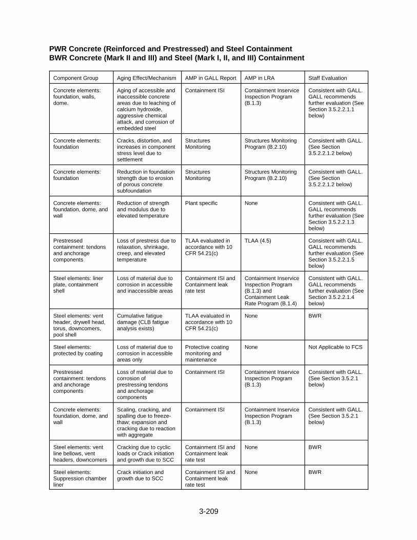
3-209
PWR Concrete (Reinforced and Prestressed) and Steel Containment BWR Concrete (Mark II and III) and Steel (Mark I, II, and III) Containment
Component Group Aging Effect/Mechanism AMP in GALL Report AMP in LRA Staff Evaluation
Concrete elements:foundation, walls,dome.
Aging of accessible andinaccessible concreteareas due to leaching ofcalcium hydroxide,aggressive chemicalattack, and corrosion ofembedded steel
Containment ISI Containment InserviceInspection Program(B.1.3)
Consistent with GALL.GALL recommendsfurther evaluation (SeeSection 3.5.2.2.1.1below)
Concrete elements:foundation
Cracks, distortion, andincreases in componentstress level due tosettlement
StructuresMonitoring
Structures MonitoringProgram (B.2.10)
Consistent with GALL.(See Section3.5.2.2.1.2 below)
Concrete elements:foundation
Reduction in foundationstrength due to erosionof porous concretesubfoundation
StructuresMonitoring
Structures MonitoringProgram (B.2.10)
Consistent with GALL.(See Section3.5.2.2.1.2 below)
Concrete elements:foundation, dome, andwall
Reduction of strengthand modulus due toelevated temperature
Plant specific None Consistent with GALL.GALL recommendsfurther evaluation (SeeSection 3.5.2.2.1.3below)
Prestressedcontainment: tendonsand anchoragecomponents
Loss of prestress due torelaxation, shrinkage,creep, and elevatedtemperature
TLAA evaluated inaccordance with 10CFR 54.21(c)
TLAA (4.5) Consistent with GALL.GALL recommendsfurther evaluation (SeeSection 3.5.2.2.1.5below)
Steel elements: linerplate, containmentshell
Loss of material due tocorrosion in accessibleand inaccessible areas
Containment ISI andContainment leakrate test
Containment InserviceInspection Program(B.1.3) andContainment LeakRate Program (B.1.4)
Consistent with GALL.GALL recommendsfurther evaluation (SeeSection 3.5.2.2.1.4below)
Steel elements: ventheader, drywell head,torus, downcomers,pool shell
Cumulative fatiguedamage (CLB fatigueanalysis exists)
TLAA evaluated inaccordance with 10CFR 54.21(c)
None BWR
Steel elements:protected by coating
Loss of material due tocorrosion in accessibleareas only
Protective coatingmonitoring andmaintenance
None Not Applicable to FCS
Prestressedcontainment: tendonsand anchoragecomponents
Loss of material due tocorrosion ofprestressing tendonsand anchoragecomponents
Containment ISI Containment InserviceInspection Program(B.1.3)
Consistent with GALL.(See Section 3.5.2.1below)
Concrete elements:foundation, dome, andwall
Scaling, cracking, andspalling due to freeze-thaw; expansion andcracking due to reactionwith aggregate
Containment ISI Containment InserviceInspection Program(B.1.3)
Consistent with GALL.(See Section 3.5.2.1below)
Steel elements: ventline bellows, ventheaders, downcomers
Cracking due to cyclicloads or Crack initiationand growth due to SCC
Containment ISI andContainment leakrate test
None BWR
Steel elements:Suppression chamberliner
Crack initiation andgrowth due to SCC
Containment ISI andContainment leakrate test
None BWR

3-210
Steel elements:drywell head anddowncomer pipes
Fretting and lock up dueto wear
Containment ISI None BWR
Class I Structures
Component Group AgingEffect/Mechanism
AMP in GALL Report AMP in LRA Staff Evaluation
All Groups exceptGroup 6: accessibleinterior/exteriorconcrete & steelcomponents
All types of agingeffects
StructuresMonitoring
Structures MonitoringProgram (B.2.10)
Consistent with GALL.(See Section3.5.2.2.2.1 below)
Groups 1-3, 5, 7-9:inaccessible concretecomponents, such asexterior walls belowgrade and foundation
Aging of inaccessibleconcrete areas due toaggressive chemicalattack, and corrosion ofembedded steel
Plant-specific None Consistent with GALL.GALL recommendsfurther evaluation (SeeSection 3.5.2.2.2.2below)
Group 6: allaccessible/inaccessibleconcrete, steel andearthen components
All types of agingeffects, including lossof material due toabrasion, cavitation,and corrosion
Inspection of Water-Control Structures orFERC/US ArmyCorps of Engineersdam inspections andmaintenance
None Not Applicable to FCS
Group 5: liners Crack initiation andgrowth from SCC andloss of material due tocrevice corrosion
Water ChemistryProgram andMonitoring of spentfuel pool water level
Chemistry Program(B.1.2)Periodic Surveillanceand PreventiveMaintenance Program(B.2.7)
Consistent with GALL.(See Section 3.5.2.1below)
Group 1-3, 5, 6: allmasonry block walls
Crack due to restraint,shrinkage, creep, andaggressiveenvironment
Masonry Wall Structures MonitoringProgram (B.2.10)
Consistent with GALL.(See Section 3.5.2.1below)
Group 1-3, 5, 7-9:foundation
Cracks, distortion, andincreases incomponent stress leveldue to settlement
StructuresMonitoring
Structures MonitoringProgram (B.2.10)
Consistent with GALL.(See Section3.5.2.2.1.2 below)
Group 1-3, 5-9:foundation
Reduction infoundation strengthdue to erosion ofporous concretesubfoundation
StructuresMonitoring
Structures MonitoringProgram (B.2.10)
Consistent with GALL.(See Section3.5.2.2.1.2 below)
Group 1-5: concrete Reduction of strengthand modulus due toelevated temperature
Plant-specific None Consistent with GALL.GALL recommendsfurther evaluation (SeeSection 3.5.2.2.1.3below)
Groups 7, 8: liners Crack initiation andgrowth due to SCC;Loss of material due tocrevice corrosion
Plant-specific None Not Applicable to FCS

3-211
Component Supports
Component Group Aging Effect/Mechanism AMP in GALL Report AMP in LRA Staff Evaluation
All Groups: support members:anchor bolts, concretesurrounding anchorbolts, welds, groutpad, boltedconnections, etc.
Aging of componentsupport
StructuresMonitoring
Structures MonitoringProgram (B.2.10)
Consistent with GALL.(See Section3.5.2.2.3.1 below)
Groups B1.1, B1.2,and B1.3: support members:anchor bolts, welds
Cumulative fatiguedamage (CLB fatigueanalysis exists)
TLAA evaluated inaccordance with 10CFR 54.21(c)
Not Applicable Consistent with GALL.GALL recommendsfurther evaluation (SeeSection 3.5.2.2.3.2below)
All Groups: supportmembers: anchorbolts, welds
Loss of material due toboric acid corrosion
Boric acid corrosion Boric Acid CorrosionPrevention Program(B.2.1)
Consistent with GALL.(See Section 3.5.2.1below)
Groups B1.1, B1.2,and B1.3: supportmembers: anchorbolts, welds, springhangers, guides,stops, and vibrationisolators
Loss of material due toenvironmentalcorrosion; loss ofmechanical function dueto corrosion, distortion,dirt, overload, etc.
ISI Inservice InspectionProgram (B.1.7)
Consistent with GALL.(See Section 3.5.2.1below)
Group B1.1: highstrength low-alloybolts
Crack initiation andgrowth due to SCC
Bolting integrity Bolting IntegrityProgram (B.1.1)
Consistent with GALL.(See Section 3.5.2.1below)
The staff’s review of the structural components for the FCS LRA is contained within foursections of this SER. Section 3.5.2.1 is the staff review of structures and structural componentsthat the applicant indicates are consistent with GALL and do not require further evaluation. Section 3.5.2.2 is the staff review of structures and structural components that the applicantindicates are consistent with GALL and for which GALL recommends further evaluation. Section 3.5.2.3 is the staff evaluation of the AMPs that are specific to the aging management ofstructural components. Section 3.5.2.4 contains an evaluation of the adequacy of agingmanagement for components in each structure and includes an evaluation of structures andstructural components that the applicant indicates are not in GALL.
3.5.2.1 Aging Management Evaluations in the GALL Report That Are Relied on forLicense Renewal, Which Do Not Require Further Evaluation
For component groups evaluated in GALL for which the applicant claimed consistency withGALL, and for which GALL does not recommend further evaluation, the staff sampledcomponents in these groups during the AMR inspection to determine whether the plant-specificcomponents contained in these GALL component groups are bounded by the GALL evaluation. The staff also sampled component groups during the AMR inspection to determine whether theapplicant properly identified those component groups in GALL that are not applicable to itsplant. The results of the staff’s AMR inspection can be found in AMR Inspection Report 50-285/03-07, dated March 20, 2003.
On the basis of its review of the inspection results, the staff finds that the applicant’s claim ofconsistency with GALL is acceptable, and that it is acceptable for the applicant to reference theinformation in the GALL Report for structures and structural components. Therefore, on thisbasis, the staff concludes that the applicant has demonstrated that the components for which

3-212
the applicant claimed consistency with GALL will be adequately managed so that the intendedfunction(s) will be maintained consistent with the CLB for the period of extended operation, asrequired by 10 CFR 54.21(a)(3) and that the USAR Supplement provides an adequatesummary description of the programs and activities credited for managing the effects of agingfor the ESF system components for which the applicant claimed consistency with GALL, asrequired by 10 CFR 54.21(d).
3.5.2.2 Aging Management Evaluations in the GALL Report that Are Relied on forLicense Renewal, For Which GALL Recommends Further Evaluation
For component groups evaluated in GALL for which the applicant has claimed consistency withGALL, and for which GALL recommends further evaluation, the staff reviewed the applicant’sevaluation to determine whether it adequately addressed the issues for which GALLrecommends further evaluation. In addition, the staff sampled components in these groupsduring the AMR inspection to determine whether the plant-specific components contained inthese GALL component groups were bounded by the GALL evaluation. The results of thestaff’s AMR inspection can be found in AMR Inspection Report 50-285/03-07, dated March 20,2003.
The GALL Report indicates that further evaluation should be performed for the followingstructures.
3.5.2.2.1 Containment
3.5.2.2.1.1 Aging of Inaccessible Concrete Areas
As stated in the SRP-LR, the GALL Report recommends further evaluation to manage theaging effects for containment concrete components located in inaccessible areas, if the agingmechanisms (1) leaching of calcium hydroxide, (2) aggressive chemical attack, or (3) corrosionof embedded steel are significant. Possible aging effects for containment concrete structuralcomponents due to these three aging mechanisms are cracking, change in material properties,and loss of material.
The AMP recommended by the GALL Report for managing the above aging effects forcontainment concrete components in accessible portions of the containment structures is theASME Section XI, Subsection IWL (XI.S2) program. The staff’s evaluation of the applicant’sASME Section XI, Subsection IWL AMP is found in Section 3.0.3.3 of this SER.
Subsection IWL exempts from examination those portions of the concrete containment that areinaccessible (e.g., foundation, below-grade exterior walls, concrete covered by liner). Forinaccessible portions of the containment structure, 10 CFR 50.55a(b)(2)(ix) requires that thelicensee evaluate the acceptability of inaccessible areas when conditions exist in accessibleareas that could indicate the presence of, or result in, degradation to inaccessible areas.
In LRA Table 3.5-1, the applicant addressed the specific criteria defined in the GALL Reportregarding the need for further evaluation to manage the potential aging of containment concretestructural components in inaccessible areas. The GALL Report recommends further evaluationfor containment concrete in inaccessible areas if the aging mechanisms (1) leaching of calciumhydroxide, (2) aggressive chemical attack, or (3) corrosion of embedded steel are significant. Regarding the aging mechanism leaching of calcium hydroxide, the applicant stated thefollowing in LRA Table 3.5-1:
3-213
Leaching of calcium hydroxide from reinforced concrete becomes significant only if the concrete isexposed to flowing water. The reinforced concrete at FCS is not exposed to flowing water.
Regarding the aging mechanism’s aggressive chemical attack and corrosion of embeddedsteel, the applicant stated the following in LRA Table 3.5-1:
Below-grade exterior reinforced concrete at FCS is not exposed to an aggressive environment (pHless than 5.5), or to chloride or sulfate solutions beyond defined limits (greater than 500 ppm chloride,or greater than 1500 ppm sulfate).
Since the below-grade reinforced concrete at FCS is not exposed to an aggressiveenvironment, the staff agrees with the applicant’s conclusion that the aging mechanismsaggressive chemical attack and corrosion of embedded steel are not likely to be significant. Inaddition, since the below-grade reinforced concrete at FCS is not exposed to flowing water, thestaff concludes that leaching of calcium hydroxide from reinforced concrete is probably notsignificant. Since these three aging mechanisms are not significant for below-grade reinforcedconcrete at FCS, the further evaluation recommended by the GALL Report is not warranted. Further discussion regarding the aging management of inaccessible containment concretecomponents is found in Section 3.5.2.4.1 of this SER.
On the basis of its review, the staff finds that the applicant has adequately evaluated themanagement of aging of inaccessible concrete areas for the containment, as recommended inthe GALL Report.
3.5.2.2.1.2 Cracking, Distortion, and Increase in Component Stress Level Due toSettlement; Reduction of Foundation Strength Due to Erosion of PorousConcrete Subfoundations, If Not Covered by Structures Monitoring Program
As stated in the SRP-LR, for the containment foundation, the GALL Report recommends furtherevaluation of cracking due to settlement and change in material properties as manifested by areduction of foundation strength due to erosion of the porous concrete subfoundation, if thesetwo effects are not covered by a structures monitoring AMP. In addition, the GALL Reportrecommends verification of the continued functionality of a de-watering system during thelicense renewal period, if relied on by the applicant to lower the site ground water level.
In LRA Table 3.5-1, the applicant addressed the above criteria defined in the GALL Reportregarding the need for further evaluation to manage the potential aging of the containmentfoundation. In row entries 3.5.1.08, 3.5.1.09, 3.5.1.21, and 3.5.1.22 of LRA Table 3.5-1, theapplicant stated that it will use the SMP to manage cracking and change in material propertiesas manifested by a reduction in strength for the containment foundation. The staff’s evaluationof the applicant’s SMP is found in Section 3.0.3.11 of this SER.
Regarding cracking due to settlement, the applicant stated the following in LRA Table 3.5-1:
The structures at FCS are supported on end-bearing steel pipe piles driven to bedrock. Settlementof the concrete subfoundation is not a plausible aging mechanism. A de-watering system is not reliedupon for control of settlement at FCS.
Regarding change in material properties as manifested by a reduction in strength, the applicantstated the following in LRA Table 3.5-1:
The reinforced concrete at FCS is not exposed to flowing water and a de-watering system is not reliedupon for control of erosion of cement from porous concrete subfoundations.

3-214
Since the applicant is managing cracking and change in material properties for the containmentfoundation as recommended by the GALL Report, the staff finds that the applicant hasadequately addressed this further evaluation criteria.
On the basis of its review, the staff finds that the applicant has adequately evaluated themanagement of cracking, distortion, and increase in component stress level due to settlement;and reduction of foundation strength due to erosion of porous concrete subfoundations forcontainment components, as recommended in the GALL Report.
3.5.2.2.1.3 Reduction of Strength and Modulus of Concrete Structures Due to ElevatedTemperature
As stated in the SRP-LR, for the containment structure, the GALL Report recommends furtherevaluation to manage the change in material properties as manifested by a reduction instrength and modulus, if any portion of the containment concrete exceeds the temperature limitof 150 �F. The GALL Report notes that the implementation of Subsection IWL examinationsand 10 CFR 50.55a would not be able to detect the reduction of concrete strength and modulusdue to elevated temperature and also notes that no mandated aging management exists formanaging this aging effect.
The GALL Report recommends that a plant-specific evaluation be performed if any portion ofthe concrete containment components exceeds specified temperature limits, viz., generaltemperature 66 °C (150 °F) and local area temperature 93 °C (200 °F). The staff verified thatthe applicant’s discussion in the renewal application indicates that the affected PWRcontainment components are not exposed to temperatures that exceed the above temperaturelimits.
In LRA Table 3.5-1, the applicant addressed the above criterion defined in the GALL Reportregarding the need for further evaluation. In row entries 3.5.1.10 and 3.5.1.23 of LRA Table3.5-1, the applicant stated the following regarding temperatures within the containmentstructure:
The maximum indoor plant temperature is 120 �F inside the main area of containment. This is belowthe temperature limit of 150 �F. Per USAR Section 5.5.4, sleeve radiation fins and thermal sleeves(in conjunction with pipe insulation) are used to limit maximum temperature at the containmentpenetration sleeves to 150 �F under operating conditions.
The nuclear detector well cooling system cools the out-of-core neutron detectors, which are locatedin tubes or wells in the reactor compartment annulus between the lower portion of the reactor vesseland the biological shield, and maintains the shield concrete temperature below 150 �F. TechnicalSpecification Limiting Condition for Operation 2.13 requires that the annulus exit temperature from thenuclear detector cooling system shall not exceed a temperature found to correlate to 150 �F concretetemperature. Therefore, no portions of concrete containment exceed specified temperature limits andno aging management is required.
By letter dated October 11, 2002, the staff issued RAI 3.5.1-3, requesting further informationregarding the correlation between the annulus exit temperature from the nuclear detectorcooling system and the concrete temperature. By letter dated December 19, 2002, theapplicant responded to this RAI, stating the following:
The Nuclear Detector Cooling System is used to cool the air in the annulus between the reactor vesseland the biological shield. While the nuclear detectors can withstand temperatures considerably higherthan 150 �F, the elevated temperature could result in reduction in concrete strength through loss ofmoisture. Each nuclear detector well cooling unit is rated at 100% of the system design capability of173,000 Btu/hr. A test was performed during Hot Functional and/or Low Power Tests to determine
3-215
(1) the correlation between annulus air temperature and concrete temperature, and (2) the rate atwhich the concrete will heat up if no cooling is available. The results of these tests were used toprovide control room indication of concrete temperatures (that is annulus air temperature) andallowable reactor operation time in the event both nuclear detector well cooling units were inoperable.The objective for this specification is to hold the concrete bulk temperature to no greater than 150 �F.Temperature sensors are installed in the concrete and in the annulus air discharge. The sensors inthe concrete are subjected to neutron flux during operation and are no longer functional. Theindicated values for annulus exit temperatures which correlate with concrete temperatures weredetermined, including a maximum value used to comply with the Tech Spec limit. A reanalysis wasperformed in 1987 to verify the original data obtained in 1973.
The staff finds that the monitoring of the concrete temperature of the biological shield wall isacceptable since the applicant has adequate procedures for ensuring that the concretetemperature will be no greater than 150 �F. As such, the applicant’s response to RAI 3.5.1-3 isacceptable.
On the basis of its review, the staff finds that the applicant has adequately evaluated themanagement of the reduction of strength and modulus of concrete structures due to elevatedtemperatures for containment concrete, as recommended in the GALL Report. Sincetemperatures within the containment structure have not exceeded the 150 �F limit, the staffconcurs with the applicant’s conclusion that further evaluation, as recommended by the GALLReport, is not required.
3.5.2.2.1.4 Loss of Material Due to Corrosion in Inaccessible Areas of Steel ContainmentShell or Liner Plate
As stated in the SRP-LR, the GALL Report recommends further evaluation to manage loss ofmaterial due to corrosion for the embedded containment liner, if corrosion of the embeddedliner is significant. The AMP recommended by the GALL Report for managing loss of materialfor accessible steel elements within the containment structure is the ASME Section XI,Subsection IWE (XI.S1) program. The staff’s evaluation of the applicant’s ASME Section XI,Subsection IWE AMP is found in Section 3.0.3.3 of this SER.
Subsection IWE exempts from examination portions of the containments that are inaccessible,such as embedded or inaccessible portions of steel liners and steel containment shells, piping,and valves penetrating or attaching to the containment. To cover inaccessible areas, 10 CFR50.55a(b)(2)(ix) requires that the licensee evaluate the acceptability of inaccessible areas whenconditions exist in accessible areas that could indicate the presence of, or result in, degradationto inaccessible areas.
In LRA Table 3.5-1, the applicant addressed the above criterion defined in the GALL Report,regarding the need for further evaluation to manage the potential aging of the embeddedcontainment liner. In row entry 3.5.1.12 of LRA Table 3.5-1, the applicant stated the followingregarding the potential for significant corrosion of the embedded steel containment liner:
Corrosion for inaccessible areas (embedded containment liner) is not significant because:
a. Concrete meeting the requirements of ACI 318 or 349 and the guidance of 201.2R wasused for the containment concrete in contact with the embedded containment liner.
b. The concrete is monitored to ensure that it is free of penetrating cracks that provide apath for water seepage to the surface of the containment shell or liner.
c. The moisture barrier, at the junction where the shell or liner becomes embedded, is subject toaging management activities in accordance with IWE requirements.
3-216
d. Borated water spills and water ponding on the containment concrete floor are notcommon and when detected are cleaned up in a timely manner.
In RAI 3.5.1-10, the staff requested further information regarding the applicant’s assertions initems (b), (c), and (d) above. Specifically, the staff requested further information regarding theapplicant’s previous monitoring, with respect to these three items, of the containment liner andmoisture barrier. In its response, the applicant stated the following:
Review of historical and recent maintenance and corrective action documents did not identify anyanomalies which could lead to significant corrosion of the inaccessible areas of the FCS containmentliner plates. The most recent inspection of the containment liner and moisture barrier was performedin April 2001 to satisfy ASME Section XI IWE requirements. The inspection identified some areas ofcorrosion on the liner near the moisture barrier and some separation and trenching of the moisturebarrier. Repairs were made to the moisture barrier during the 2002 refueling outage. This includedremoval of the top portion of the moisture barrier to inspect inaccessible sections of the liner. Onlyminor surface corrosion was found on the liner extending only 1/8" to 1/4" below the top of the existingjoint sealer. Repairs were performed to recoat the liner and restore the moisture barrier. Containmentinspections performed under the FCS Containment Inservice Inspection Program and StructuresMonitoring Program will ensure the integrity of the liner is maintained. Additional information on theliner inspection results is included in the response to RAI B.1.3-1.
Since the applicant’s inspection did not find significant corrosion in the inaccessible portion ofthe containment liner plates, and since the applicant credits its ASME Section XI, SubsectionIWE, AMP for managing loss of material for the accessible portion of the containment linerplate, the staff finds that the applicant’s response to RAI 3.5.1-10 to be acceptable. As requiredby 10 CFR 50.55a(b)(2)(ix), the applicant will inspect the inaccessible portions of thecontainment liner plates if significant corrosion of the accessible portions of the liner plate isobserved.
On the basis of its review, the staff finds that the applicant has adequately evaluated themanagement of the loss of material due to corrosion in inaccessible areas of the steelcontainment shell or liner plate for structures and structural components, as recommended inthe GALL Report. Since the corrosion of the embedded steel containment liner is notsignificant, the further evaluation recommended by the GALL Report is not warranted.
3.5.2.2.1.5 Loss of Prestress Due to Relaxation, Shrinkage, Creep, and ElevatedTemperature
As stated in the SRP-LR, the GALL Report identifies loss of prestress due to relaxation,shrinkage, creep, and elevated temperature for prestressed containment tendons andanchorage components as a TLAA to be performed for the period of extended operation. Theapplicant discussed this TLAA in Section 4.5 of the application and the staff evaluation of thisTLAA is addressed in Section 4.5 of this SER.
3.5.2.2.1.6 Cumulative Fatigue Damage
As stated in the SRP-LR, the GALL Report identifies cumulative fatigue damage as a TLAA forpenetration sleeves, penetration bellows, and dissimilar metal welds for the period of extendedoperation. The applicant discussed this TLAA in Section 4.6 of the application and the staffevaluation of this TLAA is addressed in Section 4.6 of this SER.
3.5.2.2.1.7 Cracking due to Cyclic Loading and SCC
As stated in the SRP-LR, the GALL Report recommends further evaluation of the AMPs tomanage cracking of containment penetrations (including penetration sleeves, penetration
3-217
bellows, and dissimilar metal welds) due to cyclic loading or SCC for all types of PWRcontainments. Containment ISI and leak rate testing may not be sufficient to detect cracks. Thestaff evaluated the applicant’s proposed programs to verify that adequate inspection methodswill be implemented to ensure that cracking of containment penetrations is detected.
In LRA Table 3.5-1, the applicant addressed the further evaluation recommendations in theGALL Report with regard to cracking of containment penetrations in LRA Table 3.5-1. In rowentry 3.5.1.02 of LRA Table 3.5-1, the applicant stated the following with regard to cracking dueto cyclic loading or SCC:
Stress corrosion cracking for stainless steel bellows with dissimilar metal welds is applicable only ifthe susceptible material is exposed to a corrosive environment. The bellows at FCS are not exposedto a corrosive environment; therefore, SCC is not an aging effect requiring management.
In RAI 3.5.1-9, the staff requested that the applicant clarify the above conclusion regarding thesusceptibility of bellows to SCC in a non-corrosive environment. In addition, the staff requestedthe applicant to provide further detail regarding the aging management of cracking ofcontainment penetrations in general. Specifically, the staff requested the applicant to statewhether ASME Section XI, Subsection IWE examination categories E-B (visual VT-1) and E-F(surface) of FCS bellows and dissimilar metal welds will be implemented during the period ofextended operation. In its response to RAI 3.5.1-9, the applicant stated the following:
Cracking due to cyclic loading of these bellows will be managed, per LRA AMR Item 3.5.1.02 (basedon GALL Report Items II.A3.1-c and -d), by the containment ISI (B.1.3) and leak rate (B.1.4) programswhich are consistent with programs XI.S1 and XI.S4 outlined in the GALL Report (i.e., the visualexamination categories identified in the RAI are included in the credited programs).
Relative to SCC, however, GALL Report Item II.A3.1-d identifies that “In the case of bellowsassemblies, SCC may cause aging effects particularly if the material is not shielded from a corrosiveenvironment.” For stainless steel, the corrosive environment needed for SCC to occur is a high-temperature, wetted, chloride environment (see response to RAI 3.2.1-2). At FCS, the bellows arenormally in an air environment. There are no bolted connections near these bellows assemblies thatcould result in leakage that would provide the necessary environmental conditions. LRA AMR Item3.5.1.02 Discussion column, Item 4 is based on these operating parameter assumptions.
The staff finds the applicant’s response to RAI 3.5.1-9 to be adequate since the ASME SectionXI, Subsection IWE examination categories E-B (visual VT-1) and E-F (surface) of FCS bellowsand dissimilar metal welds will be implemented during the period of extended operation. Inaddition, since the bellow assemblies are not exposed to a corrosive environment, the stafffinds that cracking due to SCC is unlikely. However, the staff notes that cracking will bemanaged by the applicant’s containment ISI and containment leak rate AMPs.
On the basis of its review, the staff finds that the applicant has adequately evaluated themanagement of cracking of containment penetrations (including penetration sleeves,penetration bellows, and dissimilar metal welds) due to cyclic loading and SCC, asrecommended in the GALL Report. A complete review of the applicant’s containment ISI andcontainment leak rate AMPs can be found in Sections 3.0.3.3 and 3.5.2.3.1, respectively, of thisSER.
3.5.2.2.1.8 Conclusions
The staff has reviewed the applicant’s evaluation of the issues for which GALL recommendsfurther evaluation for the containment structural components. On the basis of its review, thestaff finds that the applicant has provided sufficient information to demonstrate that the issuesfor which GALL recommends further evaluation have been adequately addressed and that the

3-218
subject aging effects will be adequately managed for the period of extended operation, asrequired by 10 CFR 54.21(a)(3).
The staff also reviewed the USAR Supplements for the AMPs and concludes that they provideadequate summary descriptions of the programs and activities credited for managing theeffects of aging for containment components for which the applicant claimed consistency withGALL to satisfy 10 CFR 54.21(d).
3.5.2.2.2 Class I Structures
3.5.2.2.2.1 Aging of Structures Not Covered by Structures Monitoring Program
As stated in the SRP-LR, the GALL Report recommends further evaluation for certainstructure/aging effect combinations, if they are not covered by the applicant’s SMP. Thisincludes (1) scaling, cracking, and spalling due to repeated freeze-thaw for Groups 1-3, 5, and7-9 structures; (2) scaling, cracking, spalling and increase in porosity and permeability due toleaching of calcium hydroxide and aggressive chemical attack for Groups 1-5 and 7-9structures; (3) expansion and cracking due to reaction with aggregates for Groups 1-5 and 7-9structures; (4) cracking, spalling, loss of bond, and loss of material due to corrosion ofembedded steel for Groups 1-5 and 7-9 structures; (5) cracks, distortion, and increase incomponent stress level due to settlement for Groups 1-3, 5, and 7-9 structures; (6) reduction offoundation strength due to erosion of porous concrete subfoundation for Groups 1-3 and 5-9structures; (7) loss of material due to corrosion of structural steel components for Groups 1-5and 7-8 structures; (8) loss of strength and modulus of concrete structures due to elevatedtemperatures for Groups 1-5 structures; and (9) crack initiation and growth due to SCC and lossof material due to crevice corrosion of stainless steel liner for Groups 7 and 8 structures. Further evaluation is necessary only for structure/aging effect combinations that are notcovered by the applicant’s SMP.
In LRA Table 3.5-1, the applicant addressed the above criterion defined in the GALL Report,regarding the need for further evaluation to manage the potential aging of concrete and steelstructural components. In row entry 3.5.1.16 of LRA Table 3.5-1, the applicant stated that it willuse the SMP to manage the aging effects identified in the preceding paragraph. However, theapplicant stated in row entry 3.5.1.16 that (1) none of the above aging effects have beenobserved, to date, at FCS and (2) the aging mechanisms associated with these aging effectsare not applicable.
By letter dated October 11, 2002, the staff issued RAI 3.5.1-6, requesting the applicant to clarifywhether the aging of the concrete and steel structural components, encompassed by row entry3.5.1.16 of LRA Table 3.5-1, will be managed by its SMP, as recommended by the GALLReport. By letter dated December 12, 2002, the applicant responded to RAI 3.5.1-6, stating thefollowing:
In the Discussion column of LRA AMR Item 3.5.1.16, there are nine items. Item number one indicatesthat the aging management of the concrete at FCS will be performed with a Structures MonitoringProgram that is consistent with the GALL Report. Item numbers two through nine provide specificFCS information regarding the aging mechanisms described in Chapter IIA of the GALL Report.Although the plant specific information (items two through nine) indicates aging management is notrequired, FCS has indicated in item number one that a program will be credited for managing theaging of concrete for the period of extended operation.
Since the applicant is managing the aging effects for the concrete and steel structural itemscovered by row entry 3.5.1.16 of LRA Table 3.5-1, as recommended by the GALL Report, the

3-219
staff finds that the applicant has adequately addressed this further evaluation criterion. Thestaff’s evaluation of the applicant’s SMP is found in Section 3.0.3.11 of this SER.
The staff reviewed the USAR Supplement for the SMP and concludes that it provides anadequate summary description of the programs and activities credited for managing the effectsof aging for Class I structures for which the applicant claimed consistency with GALL to satisfy10 CFR 54.21(d).
On the basis of its review, the staff finds that the applicant has adequately evaluated themanagement of aging of Class I, as recommended in the GALL Report.
3.5.2.2.2.2 Aging Management of Inaccessible Areas
As stated in the SRP-LR, the GALL Report recommends further evaluation for aging ofinaccessible concrete areas, such as below-grade foundation and exterior walls exposed toground water, due to aggressive chemical attack, if an aggressive below-grade environmentexists. An aggressive below-grade environment could result in either cracking or loss ofmaterial for concrete components subjected to such an environment. The GALL Reportrecommends that a plant-specific AMP be developed by the applicant, if an aggressive below-grade environment exists.
In LRA Table 3.5-1, the applicant addressed the above criterion defined in the GALL Report,regarding the potential aging of below-grade concrete exposed to an aggressive environment. In row entry 3.5.1.17 of LRA Table 3.5-1, the applicant stated the following:
Below-grade exterior reinforced concrete at FCS is not exposed to an aggressive environment (pHless than 5.5), or to chloride or sulfate solutions beyond defined limits (greater than 500 ppm chloride,or greater than 1500 ppm sulfate). Periodic monitoring of below-grade water chemistry will beconducted during the period of extended operation to demonstrate that the below-grade environmentis not aggressive.
In RAIs 3.5.1-19 and 3.5.1-8, the staff requested further information regarding (1) the groundwater chemistry and (2) the monitoring of ground water chemistry to ensure that the below-grade environment is not aggressive. In its response to RAI 3.5.1-19, the applicant stated thefollowing:
The Missouri River water was tested periodically from 1973 to 1981. The results showed a pHaverage of 8.16, chlorides of 12.7 ppm, and sulfates of 200.6 ppm (USAR Section 2.7.1.4 in Table 2.7-3). River water test results from samples taken annually between 1990 and 1999 showed a pHaverage of 8.24.
The groundwater was tested in August 1966 and the average results showed a pH of 7.3, chloridecontent of 34 ppm, and sulfate content of 162 ppm (USAR Section 2.7.2.3 in Table 2.7-4).
To verify the river water and groundwater chemistry had not significantly changed over 20-30 years,a chemical analysis was performed in June 2000. Those test results indicated the groundwater pHwas 7.48, chlorides were 8.0 ppm, and sulfates were 79.0 ppm; river water pH was 8.39, chlorideswere 14.0 ppm, and sulfates were 229 ppm.
In its response to RAI 3.5.1-8, the applicant stated the following:
Ground water and river water samples were taken in June 2000 and evaluation results were comparedto samples taken during plant construction. No significant deviation in sample results was identified.A periodic task will be initiated as part of the Structures Monitoring Program (B.2.10) to take groundwater samples on a five year frequency and compare the evaluation results to previous samples.

3-220
Since the ground water and river water chemistry parameters (pH, sulfates, and chlorides)indicate a non-aggressive environment, the staff concurs with the applicant’s conclusion thatfurther evaluation, as recommended by the GALL Report, is unnecessary. In addition, theapplicant has committed to monitor and evaluate the ground water periodically during the periodof extended operation. As such, RAIs 3.5.1-8 and 3.5.1-19 are considered closed.
On the basis of its review, the staff finds that the applicant has adequately evaluated thepotential aging of below-grade concrete components exposed to ground water due to anaggressive environment. Since the below-grade environment is not aggressive, the furtherevaluation recommended by the GALL Report is not warranted.
On the basis of its review, the staff finds that the applicant has adequately evaluated themanagement of inaccessible areas for Class I structures, as recommended in the GALL Report.
3.5.2.2.2.3 Conclusions
The staff has reviewed the applicant’s evaluation of the issues for which GALL recommendsfurther evaluation for Class I structures. On the basis of its review, the staff finds that theapplicant has provided sufficient information to demonstrate that the issues for which GALLrecommends further evaluation have been adequately addressed and that the subject agingeffects will be adequately managed for the period of extended operation, as required by 10CFR 54.21(a)(3).
The staff also reviewed the USAR Supplement for the AMPs and concludes that they provideadequate summary descriptions of the programs and activities credited for managing theeffects of aging for Class I structures for which the applicant claimed consistency with GALL tosatisfy 10 CFR 54.21(d).
3.5.2.2.3 Component Supports
3.5.2.2.3.1 Aging of Supports Not Covered by Structures Monitoring Program
As stated in the SRP-LR, the GALL Report recommends further evaluation of certaincomponent support/aging effect combinations if they are not covered by the SMP. Thisincludes (1) reduction in concrete anchor capacity due to degradation of the surroundingconcrete, for Groups B1-B5 supports; (2) loss of material due to environmental corrosion, forGroups B2-B5 supports; and (3) reduction/loss of isolation function due to degradation ofvibration isolation elements, for Group B4 supports. Further evaluation is necessary only forthe structure/aging effect combinations, listed above, that are not covered by the applicant’sSMP.
In LRA Table 3.5-1, the applicant addressed the above criterion defined in the GALL Report,regarding the need for further evaluation to manage the potential aging of component supports. In row entry 3.5.1.25 of LRA Table 3.5-1, the applicant stated that it will use the SMP tomanage the aging effects identified in the preceding paragraph.
Since the applicant is managing the aging effects for the component supports covered by rowentry 3.5.1.25 of LRA Table 3.5-1, as recommended by the GALL Report, the staff finds thatthe applicant has adequately addressed this further evaluation criterion. The staff’s evaluationof the applicant’s SMP is found in Section 3.0.3.11 of this SER.

3-221
The staff reviewed the USAR Supplement for the SMP and concludes that it provides anadequate summary description of the programs and activities credited for managing the effectsof aging for component supports for which the applicant claimed consistency with GALL tosatisfy 10 CFR 54.21(d).
On the basis of its review, the staff finds that the applicant has adequately evaluated themanagement of aging of component supports, as recommended in the GALL Report.
3.5.2.2.3.2 Cumulative Fatigue Damage due to Cyclic Loading
As stated in the SRP-LR, the GALL Report identifies cumulative fatigue damage as a TLAA forsupport members, anchor bolts, and welds for Groups B1.1, B1.2, and B1.3 componentsupports, if a CLB fatigue analysis exists. Since a CLB fatigue analysis does not exist at FCS,cumulative fatigue damage for component supports is not addressed by the applicant.
3.5.2.2.3.3 Conclusions
The staff has reviewed the applicant’s evaluation of the issues for which GALL recommendsfurther evaluation for component supports. On the basis of its review, the staff finds that theapplicant has provided sufficient information to demonstrate that the issues for which the GALLrecommends further evaluation have been adequately addressed and that the subject agingeffects will be adequately managed for the period of extended operation, as required by 10CFR 54.21(a)(3).
The staff also reviewed the USAR Supplement for the SMP and concludes that it provides anadequate summary description of the programs and activities credited for managing the effectsof aging for component supports for which the applicant claimed consistency with GALL tosatisfy 10 CFR 54.21(d).
3.5.2.3 Aging Management Programs for Containment, Structures, and ComponentSupports
In SER Section 3.5.2.1, the staff evaluated the applicant’s conformance with the agingmanagement recommended by GALL for containment, other Class I structures, and componentsupport component groupings. In SER Section 3.5.2.2, the staff reviewed the applicant’sevaluation of the issues for which GALL recommends further evaluation. In this SER section,the staff presents its evaluation of the programs used by the applicant to manage the aging ofthe component groups within the containment, other Class I structures, and componentsupports.
The applicant credits 13 AMPs to manage the aging effects associated with the containment,other Class I structures, and component supports. Eleven of the AMPs are credited withmanaging aging for components in other system groups (common AMPs) while two AMPs arecredited with managing aging only for structures and structural components. The staff’sevaluation of the common AMPs credited with managing aging in structures and structuralcomponents is provided in Section 3.0.3 of this SER. The common AMPs are listed here:
• Bolting Integrity Program - SER Section 3.0.3.1• Chemistry Program - SER Section 3.0.3.2• Containment Inservice Inspection Program - SER Section 3.0.3.3• Inservice Inspection Program - SER Section 3.0.3.5• Boric Acid Corrosion Prevention Program - SER Section 3.0.3.6
3-222
• Cooling Water Corrosion Program - SER Section 3.0.3.7• Fire Protection Program - SER Section 3.0.3.9• Periodic Surveillance and Preventive Maintenance Program - SER Section 3.0.3.10• Structures Monitoring Program - SER Section 3.0.3.11• General Corrosion of External Surfaces Program - SER Section 3.0.3.12• Selective Leaching Program - SER Section 3.0.3.14
The staff’s evaluation of the two structure-specific AMPs are provided in the sections below.
3.5.2.3.1 Containment Leak Rate Program
The applicant described its containment leak rate program in Section B.1.4 of the LRA. Theapplicant credits this program with managing the potential aging of containment structures andcomponents that are within the scope of license renewal and subject to an AMR. The staffreviewed the containment leak rate program to determine whether the applicant hasdemonstrated that the program will adequately manage the applicable effects of aging duringthe period of extended operation, as required by 10 CFR 54.21(a)(3).
3.5.2.3.1.1 Summary of Technical Information in the Application
The LRA states that the containment leak rate program is consistent with GALL program XI.S4,“10 CFR Part 50, Appendix J,” and applicable sections of GALL program XI.S1, “ASME XI,Subsection IWE,” related to Appendix J testing. In addressing the operating experience relatedto the program, the applicant stated that containment leaktight verification and visualexamination of the steel components that are part of the leaktight barrier have been conductedat FCS since initial unit startup. Prior to the development of the ASME Section XI, SubsectionIWE Inservice Inspection Program, examinations were performed in accordance with 10 CFRPart 50, Appendix J. No significant age-related degradation has been identified in theinspections performed.
3.5.2.3.1.2 Staff Evaluation
Section B.1.4 of the LRA describes the applicant’s containment leak rate program. The LRAstates that this AMP is consistent with GALL program XI.S4, “10 CFR Part 50, Appendix J,” andapplicable sections of GALL program XI.S1, “ASME XI, Subsection IWE,” related to Appendix Jtesting, with no deviations. The staff also reviewed the USAR Supplement to determinewhether it provides an adequate description of the program.
In addition to the review of Section B.1.4 of the LRA, the staff also reviewed the relevantportions of Section 3.5, “Aging Management of Containment, Structures, and ComponentSupports,” and Section B.1.3, “Containment Inservice Inspection Program,” of the LRA tocorrelate the results of the AMR and AMPs related to the containment.
The applicant’s containment leak rate testing program is consistent with the provisions of GALLprogram XI.S4. Though the applicant does not explicitly describe the program as the one whichassures the leaktight integrity of the FCS containment, GALL program XI.S4 describes theprogram as one that assures the essentially leaktight characteristics of the containmentpressure boundary. Thus, the staff considers the basic purpose of the program is to ensure theleaktight integrity of the FCS containment. However, when a component shows a higher thanacceptable leak rate, the cause could be related to the aging degradation of the component.
3-223
In response to a question related to the operating experience associated with Type A, Type B,and Type C tests (RAI B.1.4-1, issued by the staff on October 11, 2002), by letter datedDecember 12, 2002, the applicant indicated that none of the tests have exceeded twice theacceptance criteria for those components, i.e., containment structure, containmentpenetrations, and containment isolation valves. The staff considers the condition of thecomponents adequate.
The applicant provided a summary description of the containment leak rate program in SectionA.2.7 of the LRA. The description of the program cites the references that are being used inimplementing the plant-specific program, and specifies that corrective actions are taken ifleakage rates exceed the acceptance criteria. The staff considers the description of theprogram in the USAR Supplement acceptable.
3.5.2.3.1.3 Conclusion
On the basis of its review of the applicant’s program, the staff finds that those portions of theprogram for which the applicant claims consistency with GALL are consistent with GALL. Thestaff also reviewed the USAR Supplement for this AMP and finds that it provides an adequatesummary description of the program, as required by 10 CFR 54.21(d).
Therefore, on the basis of its review, the staff concludes that the applicant has demonstratedthat the containment leak rate program will effectively manage aging in the structures andcomponents for which this program is credited, so that the intended functions of the associatedcomponents and systems will be maintained consistent with the CLB for the period of extendedoperation, as required by 10 CFR 54.21(a)(3).
3.5.2.3.2 Overhead Load Handling Systems Inspection Program
The overhead load handling systems inspection program is described in Section B.2.6 ofAppendix B to the LRA. The program manages the effects of general corrosion on the craneand trolley structural components for those cranes that are within scope and subject to an AMR,and the effects of wear on the rails in the rail system. The staff reviewed the LRA to determinewhether the applicant has demonstrated that the overhead load handling systems inspectionprogram will adequately manage the aging effects for the components that credit this programthroughout the period of extended operation, as required by 10 CFR 54.21(a)(3).
3.5.2.3.2.1 Summary of Technical Information in the Application
The applicant states that the overhead load handling systems inspection program is consistentwith GALL program XI.M23, “Inspection of Overhead Heavy Load and Light Load (Related toFueling) Handling Systems,” with enhancements. The enhancements relate to expansionanchors and cover such items as establishing inspection guidance and acceptance criteria forgeneral corrosion of the expansion anchor and cracking of the surrounding concrete.
Sections 2 and 3 of the LRA identify those components for which the overhead load handlingsystems inspection program is credited as an AMP. The AMR for the overhead load handlingsystems refers to Table 3.3-1 of the LRA, which indicates that the aging management of theseitems is consistent with GALL.
The applicant’s operating experience indicates that no aging effects which impact the intendedfunctions of the structures or components were identified in the inspections performed.
3-224
3.5.2.3.2.2 Staff Evaluation
In LRA Section B.2.6, “Overhead Load Handling Systems Inspection Program,” the applicantdescribed its AMP to manage overhead load handling systems. The LRA states that this AMPis consistent with GALL program XI.M23, “Inspection of Overhead Heavy Load and Light Load(Related to Fueling) Handling Systems,” with an enhancement related to the inspection of theanchor bolts for the load handling systems. The staff confirmed the applicant’s claim ofconsistency during the AMR inspection. Furthermore, the staff reviewed the enhancement andits justification to determine whether the AMP, with the enhancement, remains adequate tomanage the aging effects for which it is credited, and reviewed the USAR Supplement todetermine whether it provides an adequate description of the program.
The staff verified that the components in LRA Table 2.4.2.5-1 to which this program applies arecommensurate with the intent of the GALL program X1.M23. The enhancements to severalelements in the GALL program identified in the LRA were also reviewed. These enhancementswould add more specific guidance for detection of aging effects, acceptance criteria, andcorrective actions relating to concrete anchors for the equipment included in the program. Since the applicant is not taking any exception to GALL Report program X1.M23, but simplyadding more specific guidance in the inspection procedures, the staff finds the enhancementsreasonable and acceptable.
The staff reviewed the summary description of the overhead load handling inspection programin Appendix A of the LRA. The staff finds that the information in the USAR Supplementprovides an adequate summary of the program activities as required by 10 CFR 54.21(d).
3.5.2.3.2.3 Conclusion
On the basis of its review and inspection of the applicant’s program, the staff finds that thoseportions of the program for which the applicant claims consistency with GALL are consistentwith GALL. In addition, the staff has reviewed the enhancements to the GALL program andfinds that the applicant’s program provides for adequate management of the aging effects forwhich the program is credited. The staff also reviewed the USAR Supplement for this AMP andfinds that it provides an adequate summary description of the program, as required by 10 CFR54.21(d).
Therefore, on the basis of its review, the staff concludes that the applicant has demonstratedthat the overhead load handling systems inspection program will effectively manage aging inthe structures and components for which this program is credited, so that the intended functionsof the associated components and systems will be maintained consistent with the CLB for theperiod of extended operation, as required by 10 CFR 54.21(a)(3).
3.5.2.4 Aging Management Review of Plant-Specific Structures and StructuralComponents
In this section of the SER, the staff presents its review of the applicant’s AMRs for specificstructures and structural components. To perform its evaluation, the staff reviewed thecomponents listed in LRA Tables 2.4.2.1-1 through 2.4.2.7-1 to determine whether the applicantproperly identified the applicable aging effects and AMPs needed to adequately manage theseaging effects. This portion of the staff’s review involved identification of the aging effects foreach component, ensuring that each component was evaluated in the appropriate LRA AMRTable in Section 3, and that management of the aging effect was captured in the appropriateAMP. The results of the staff’s review are provided below.

3-225
3.5.2.4.1 Containment
3.5.2.4.1.1 Summary of Technical Information in the Application
The AMR results for the containment are presented in Tables 3.5-1, 3.5-2, and 3.5-3 of theLRA. The applicant used the GALL Report format to present its AMR of containmentcomponents in LRA Table 3.5-1. In LRA Tables 3.5-2 and 3.5-3, the applicant identified thecomponent group designation along with its (1) material, (2) environment, (3) aging effect(s),and (4) AMP(s).
As described in Section 2.4.1 of the LRA, the containment structure is a partially prestressed,reinforced concrete, Class I structure composed of a cylindrical wall, domed roof, and a bottommat. The mat is common to both the containment structure and the auxiliary building and issupported on steel piles driven to bedrock. The containment has a 1/4 inch internal carbonsteel liner. The materials of construction for the containment structure, as shown in Table2.4.1-1 of the LRA, are steel, concrete, and miscellaneous materials such as calcium silicateand elastomers. These materials are exposed to containment air, indoor (ambient) air, outdoorair, borated water, treated water, and a buried environment.
Aging Effects
The LRA identifies the following aging effects for the containment structure:
• cracking, loss of material, and change in material properties for concrete components• cracking, loss of material, and change in material properties for containment grout• cracking for masonry block walls• cumulative fatigue, cracking, and loss of material for steel containment penetrations• loss of material for carbon steel structural components• loss of prestress for containment tendons• loss of seal for elastomers
Aging Management Programs
The LRA credits the following AMPs with managing the identified aging effects for thecontainment structure:
• Containment Inservice Inspection Program• Chemistry Program• Fire Protection Program• Containment Leak Rate Program• Structures Monitoring Program
A description of these AMPs is provided in Appendix B of the LRA.
3.5.2.4.1.2 Staff Evaluation
In addition to Section 3.5 of the LRA, the staff reviewed the pertinent information provided inSection 2.4, “Scoping and Screening Results: Structures,” and the applicable AMP descriptionsprovided in Appendix B of the LRA, to determine whether the aging effects for the containmentcomponents have been properly identified and will be adequately managed during the period ofextended operation, as required by 10 CFR 54.21(a)(3).

3-226
This section of the SER provides the staff’s evaluation of the applicant’s AMR for the agingeffects and the appropriateness of the programs credited for the aging management of thecontainment structural components at FCS. The staff’s evaluation includes a review of theaging effects considered and the basis for the applicant’s elimination of certain aging effects. Inaddition, the staff has evaluated the appropriateness of the AMPs that are credited formanaging the identified aging effects for the containment components.
Aging Effects
Concrete: For containment concrete components, the applicant’s AMR is consistent with therecommendations in the GALL Report. As such, the applicant has committed to managecracking, change in material properties, and loss of material for containment concretecomponents that are accessible. However, for several of the table entries in LRA Table 3.5-1,the applicant stated that the aging effect/mechanism combinations identified in the GALLReport are not applicable to FCS. In RAIs 3.5-1, 3.5.1-7, 3.5.1-12, 3.5.1-15, and 3.5.1-16, thestaff requested that the applicant clarify its intentions to manage the aging effect/mechanismcombinations as recommended by the GALL Report. In its response to these RAIs, theapplicant stated the following:
For concrete at FCS, even though OPPD has concluded that the AERMs identified for concrete in theGALL Report are not applicable due to the plant’s operating experience, OPPD has committed to beconsistent with the GALL Report and monitor for the possibility of the AERMs with the programsidentified in the GALL Report.
The staff takes exception to the applicant’s claim that the aging effects identified in the GALLReport are not applicable for concrete at FCS; however, since the applicant has committed tomonitor for these aging effects using the appropriate AMPs, the staff considers the applicant’sresponse to be adequate. As such, the staff considers RAIs 3.5-1, 3.5.1-7, 3.5.1-12, 3.5.1-15,and 3.5.1-16 closed.
In RAI 3.5.1-2, the staff requested further information regarding the LRA Table 2.4.1-1 entryentitled, “Containment Grout in Ambient Air.” Specifically, the staff asked the applicant forfurther information regarding the location of the grout within the containment and the agingmanagement of the grout. In response to RAI 3.5.1-2, the applicant stated the following:
“Containment Grout in Ambient Air” includes grout under baseplates that are not typically exposed tofluids, flowing or otherwise. The table referenced in the RAI provides links to LRA AMR Items that areconsistent with the recommendations in the GALL Report and credit the recommended AMPs.
Since the applicant has committed to manage the aging of grout within the containment asrecommended by the GALL Report, the staff considers the applicant’s response to RAI 3.5.1-2adequate.
In RAI 3.5.3-1, the staff requested further information regarding the aging management of theungrouted masonry walls in the containment. Specifically, the staff requested that the applicantprovide further information concerning the (1) location of these walls, (2) environment to whichthey are subjected, (3) time-interval for examining the walls, and (4) operating experiencerelated to these walls. In response to RAI 3.5.3-1, the applicant provided a map showing thelocation of the ungrouted masonry walls. There are four ungrouted masonry walls at the 989 ftelevation level of the containment. The temperature, humidity, and radiation level that thesewalls are exposed to are 120 �F, 20 to 100 percent, and 10 R/hr averaged over a 40 year life,respectively. The applicant also stated that the masonry walls in the containment are inspectedduring the performance of the containment inspection surveillance test, which is performed
3-227
every other refueling outage. In addition, the applicant stated that containment inspectionsperformed in 1996, 1999, and 2002, did not identify any degradation of the masonry walls. Thestaff considers that the applicant’s response to RAI 3.5.3-1 adequately demonstrates that thereis no significant degradation of the ungrouted masonry walls in the containment, and that theaging of these walls will be adequately monitored during the period of extended operation.
For below-grade containment concrete components, the GALL Report recommends agingmanagement only for an aggressive below-grade soil/ground water environment. Since ASMESection XI, Subsection IWL exempts from examination those portions of the concretecontainment that are inaccessible, the GALL Report recommends that a plant-specific AMP bedeveloped for concrete that may be exposed to an aggressive below-grade soil/ground waterenvironment. As stated previously in SER Sections 3.5.2.2.1.1 and 3.5.2.2.2.2, the applicantadequately demonstrated that the ground water chemistry parameters (pH, sulfates, andchlorides) indicate a non-aggressive environment. Therefore, a plant-specific AMP for below-grade concrete components is not warranted. However, 10 CFR 50.55a(b)(2)(ix) requires thatthe licensee evaluate the acceptability of inaccessible areas when conditions exist in accessibleareas that could indicate the presence of, or result in, degradation to such inaccessible areas.
In RAI 3.5.1-1, the staff requested further information concerning (1) the condition of thecontainment tendon gallery, which is below-grade and accessible for inspection, and (2) thepossibility of using the condition of the below-grade containment tendon gallery as an indicatorfor the aging of other inaccessible containment concrete components. In response to RAI3.5.1-1, the applicant stated the following:
The exterior of the below-grade concrete wall of the tendon gallery is, by definition, inaccessible forinspection. If the reviewer is implying that inspections of the inside of the below-grade tendon gallerywall will provide evidence that the environment on the outside of the wall is not adversely affecting theconcrete, then the results of these inspections performed to date indicate that no external degradationis occurring. Although the tendon gallery is not part of the Containment boundary, it is included as partof the Containment inspections. In October 1999, there was no evidence of active concretedegradation (i.e., no residue indicating spalling concrete). Additionally, there were no signs of activeseepage and all surfaces were dry. Fine cracks that had been noted in earlier inspections andmonitored in subsequent inspections showed no signs of movement from those previous inspections.
Since the applicant’s previous inspections of the containment tendon gallery indicate that thereis not any significant aging, and since the ground water chemistry parameters are within thebounds recommended by the GALL Report, the staff concurs with the applicant’s assertion thatexternal degradation of below-grade concrete components is not likely to be significant. In theevent that below-grade structural components are exposed by excavation, the applicant stated,in LRA Section B.2.10, “Structures Monitoring Program,” that guidance will be added to inspectthese components.
The staff finds that the applicant’s approach for evaluating the applicable aging effects forconcrete components in containment to be reasonable and acceptable. The staff concludesthat the applicant has properly identified the aging effects for concrete components incontainment.
Steel: Consistent with the GALL Report recommendations, the applicant identified loss ofmaterial for containment carbon steel structural components, and cumulative fatigue, cracking,and loss of material as applicable aging effects for steel containment penetrations. Loss ofprestress for containment tendons is also identified as an applicable aging effect by theapplicant.
3-228
Loss of material due to corrosion of the embedded containment liner and cracking ofcontainment penetrations due to cyclic loading are identified by the GALL Report as agingeffects requiring further evaluation and are covered in detail in Sections 3.5.2.2.1.4 and3.5.2.2.1.7, respectively, of this SER. Loss of prestress for containment tendons is evaluatedas a TLAA and reviewed by the staff in Section 4.5 of this SER.
For stainless steel components that are exposed to only ambient air, the applicant did notidentify any applicable aging effects. This latter category includes stainless steel threadedfasteners. In RAI 3.5.1-11, the staff requested that the applicant justify its conclusion regardingthe aging management of stainless steel threaded fasteners. Specifically, the staff pointed outthat these stainless steel fasteners may be subject to aging effects if exposed to a wetted ormoist environment. In its response the applicant stated the following:
These stainless steel threaded fasteners are for the fuel transfer tube blind flange (containment side).The blind flange is removed prior to filling the refueling canal; therefore, the fasteners are not subjectto an environment that would support aging effects.
Since the stainless steel threaded fasteners are not exposed to a wetted or moist environment,the staff supports the applicant’s conclusion that there are no applicable aging effects for thesefasteners. As such, the staff considers RAI 3.5.1-11 to be resolved.
The staff finds that the applicant’s approach for evaluating the applicable aging effects for steelcomponents in containment to be reasonable and acceptable. The staff concludes that theapplicant has properly identified the aging effects for steel components in containment.
Elastomers (moisture barriers, seals): Consistent with the GALL Report recommendations, theapplicant identified loss of seal as an applicable aging effect for the equipment hatch gasket,which is made of neoprene.
The staff finds that the applicant’s approach for evaluating the applicable aging effect forelastomers in containment to be reasonable and acceptable. The staff concludes that theapplicant has properly identified the aging effect for elastomers in containment.
On the basis of its review, the staff finds the applicant has identified the appropriate agingeffects for the materials and environments associated with the containment.
Aging Management Programs
Tables 3.5-1 through 3.5-3 of the LRA credit the following AMPs with managing the identifiedaging effects for the components in the containment:
• Containment Inservice Inspection Program• Chemistry Program• Fire Protection Program• Containment Leak Rate Program• Structures Monitoring Program
With the exception of the containment leak rate program, each of the above AMPs are creditedwith managing the aging of several components in several different structures and systems andare, therefore, considered common AMPs. The staff’s review of the common AMPs is inSection 3.0.3 of this SER. The staff’s evaluation of the containment leak rate program ispresented in Section 3.5.2.3.1 of this SER.

3-229
After evaluating the applicant’s AMR for each of the components in the containment, the staffevaluated the AMPs listed above to determine if they are appropriate for managing theidentified aging effects. For those components identified in Table 3.5-1 of the LRA, the staffverified that the applicant credited the AMPs recommended by the GALL Report. For thecomponents identified in LRA Tables 3.5-2 and 3.5-3, the staff verified that the applicantcredited an AMP that is appropriate for the identified aging effect(s).
On the basis of its review, the staff finds the applicant has credited the appropriate AMPs tomanage the aging effects for the materials and environments associated with containment. Inaddition, the staff found the associated program descriptions in the USAR Supplement to beacceptable to satisfy 10 CFR 54.21(d).
3.5.2.4.1.3 Conclusions
The staff has reviewed the information in Sections 2.4 and 3.5 of the LRA, the applicant’sresponses to the staff’s RAIs, and the applicable AMP descriptions in Appendix B of the LRA. On the basis of this review, the staff concludes that the applicant has demonstrated that theaging effects associated with the components in the containment will be adequately managedso that these components will perform their intended functions in accordance with the CLBduring the period of extended operation, as required by 10 CFR 54.21(a)(3).
The staff also reviewed the applicable USAR Supplement program descriptions and concludesthat the USAR Supplements provide adequate program descriptions of the AMPs credited formanaging aging in the containment to satisfy 10 CFR 54.21(d).
3.5.2.4.2 Other Structures
3.5.2.4.2.1 Summary of Technical Information in the Application
The AMR results for structures outside the containment are presented in Tables 3.3-1, 3.3-2,3.5-1, 3.5-2, and 3.5-3 of the LRA. The applicant used the GALL Report format to present itsAMR of structural components in LRA Table 3.5-1. In LRA Tables 3.5-2 and 3.5-3, theapplicant identified the component group designation along with its (1) material, (2)environment, (3) aging effect(s), and (4) AMP(s). The structural components listed in Tables3.5-1 through 3.5-3 of the LRA are in the following structures:
• auxiliary building• turbine building • service building• intake structure• building piles
A brief description of each of the above structures is provided in Section 2.4.2, "OtherStructures," of the LRA. For each structure in LRA Section 2.4.2, the applicant also provides alist of the in-scope components in an accompanying table. In addition to the in-scope structuralcomponents identified in LRA Section 2.4.2, in response to Open Item 2.3.3.15-1, the applicantalso brought the circulating water discharge tunnel into scope. The applicant stated that thetunnel would be included as part of the intake structure. The staff has determined that the in-scope structural components of the circulating water tunnel are already identified in the intakestructure. Therefore, the aging management review results for the intake structure areapplicable to the circulating water discharge tunnel.

3-230
The materials of construction identified in the LRA for each of the above structures are (1)steel, (2) concrete, (3) elastomers, (4) fire protection materials, (5) polyvinyl chloride (PVC), (6)earth fill, (7) cast iron, (8) bronze, and (9) brass. These materials are exposed to outdoor,buried, indoor, borated water, and raw water environments.
Aging Effects
Tables 3.5-1 through 3.5-3 of the LRA identify the following applicable aging effects forcomponents in structures outside the containment:
• loss of material• change in material properties• cracking• separation• loss of mechanical function• reduction in concrete anchor capacity
Aging Management Programs
Tables 3.5-1 through 3.5-3 of the LRA credit the following AMPs with managing the identifiedaging effects for the components in structures outside the containment:
• Chemistry Program• Inservice Inspection Program• Fire Protection Program• Periodic Surveillance and Preventive Maintenance Program• Structures Monitoring Program• General Corrosion of External Surfaces Program• Selective Leaching Program• Cooling Water Corrosion Program
A description of these AMPs is provided in Appendix B of the LRA.
3.5.2.4.2.2 Staff Evaluation
In addition to Section 3.5 of the LRA, the staff reviewed the pertinent information provided inSection 2.4, “Scoping and Screening Results: Structures,” and the applicable AMP descriptionsprovided in Appendix B of the LRA to determine whether the aging effects for the componentsin structures outside the containment have been properly identified and will be adequatelymanaged during the period of extended operation, as required by 10 CFR 54.21(a)(3).
This section of the SER provides the staff’s evaluation of the applicant’s AMR for the agingeffects and the appropriateness of the programs credited for the aging management ofstructural components at FCS. The staff’s evaluation includes a review of the aging effectsconsidered and the basis for the applicant’s elimination of certain aging effects. In addition, thestaff has evaluated the appropriateness of the AMPs that are credited for managing theidentified aging effects for the components in structures outside of containment.
Aging Effects
Concrete: For concrete components in structures outside the containment, the applicant’s AMRis consistent with the recommendations in the GALL Report. As such, the applicant has

3-231
committed to manage cracking, change in material properties, and loss of material for concretestructural components that are accessible. As stated previously in Section 3.5.2.4.1.2 of thisSER, the applicant stated in LRA Table 3.5-1 that, although they are consistent with the GALLReport, they do not consider the aging effects/mechanisms identified by the GALL for concreteto be applicable to concrete structures at FCS. To clarify the applicant’s intent with regard tothe aging management of concrete structural components, the staff requested in several RAIs(3.5-1, 3.5.1-7, 3.5.1-12, 3.5.1-15, and 3.5.1-16) that the applicant provide further informationregarding this apparent discrepancy. In response, the applicant stated that although they donot consider these aging effects to be applicable, they will manage the aging of concretestructures at FCS as recommended by the GALL Report. Since the applicant clarified itsintentions to manage the aging of concrete structures at FCS, the staff considers the responseto the staff’s RAIs adequate.
For below-grade concrete structural components, the GALL Report recommends agingmanagement only for an aggressive below-grade soil/ground water environment. As statedpreviously in SER Section 3.5.2.2.2.2, the applicant adequately demonstrated that the groundwater chemistry parameters (pH, sulfates, and chlorides) indicate a non-aggressiveenvironment. Therefore, aging management of below-grade concrete components is notwarranted. To insure that the below-grade environment remains non-aggressive, the applicanthas committed to periodically monitor the ground water chemistry through its structuralmonitoring program.
The staff finds that the applicant’s approach for evaluating the applicable aging effects forconcrete components in structures outside the containment to be reasonable and acceptable. The staff concludes that the applicant has properly identified the aging effects for concretecomponents in these structures.
Steel: Consistent with the recommendations of the GALL Report, the applicant identified loss ofmaterial as an applicable aging effect for carbon steel components in structures outside thecontainment. This includes all Class I structures identified in the GALL Report. For carbonsteel expansion/grouted anchors, the applicant identified loss of material and reduction inconcrete anchor capacity as applicable aging effects. These steel expansion/grouted anchorsare found in the auxiliary building, turbine and service buildings, and intake structure.
For below-grade pipe piles, the applicant did not identify any applicable aging effects. Thisposition is consistent with the agreement in NUREG 1557, “Summary of Technical Informationand Agreements from Nuclear Management and Resource Council Industry ReportsAddressing License Renewal,” which states the following:
Steel piles driven in undisturbed soils have been unaffected by corrosion and those driven in disturbedsoil experience minor to moderate corrosion to a small area of metal.
For stainless steel components, the applicant identified loss of material as an applicable agingeffect for (1) the intake structure pump gland bolting, which is exposed to raw water and (2) thefuel transfer penetration fasteners, which are exposed to borated treated water. The applicantalso identifies cracking as an applicable aging effect for the stainless steel spent fuel pool liner,the refueling canal liner, and the pipe penetrations for the safety injection and refueling watertank. For structural stainless steel in ambient air the applicant did not identify any applicableaging effects.
The staff finds that the applicant’s approach for evaluating the applicable aging effects for steelcomponents in structures outside the containment to be reasonable and acceptable. The staff

3-232
concludes that the applicant has properly identified the aging effects for steel components inthese structures.
Elastomers: For the auxiliary building and intake structure flood panel seals, the applicantidentified change in material properties and cracking as applicable aging effects. Since neitherof these components are identified in the GALL Report, the applicant lists these items in LRATable 3.5-2. The staff concurs with the applicant’s identification of these two aging effects forelastomer material components.
The staff finds that the applicant’s approach for evaluating the applicable aging effects forelastomers in structures outside the containment to be reasonable and acceptable. The staffconcludes that the applicant has properly identified the aging effects for elastomers in thesestructures.
Fire Protection Materials (glass, mineral fiber, pyrocrete, masonry): For the glass used in themetal fire penetration barriers, the applicant did not identify any applicable aging effects. Formineral fiber and pyrocrete fire barriers, the applicant identified separation, cracking, and lossof material as applicable aging effects. For masonry block walls used as fire barriers, theapplicant identified cracking as an applicable aging effect.
The staff concurs with the applicant’s identification of the applicable aging effects for thepyrocrete fire barriers and masonry block walls. For the glass used in metal fire penetrationbarriers, the staff concurs with the applicant’s conclusion that there are no applicable agingeffects.
Miscellaneous Metals (cast iron, bronze, brass): For the cast iron stuffing box floor penetrationin the intake structure, the applicant identified loss of material as an applicable aging effect. The applicant did not identify any aging effects for the auxiliary building removable slab liftingdevices, which are made from bronze. Cast iron, bronze, and brass are used for gland andgland bolting in the intake structure. Since the gland bolting is in a raw water environment, theapplicant identified loss of material as an applicable aging effect.
The staff concurs with the applicant’s identification of loss of material as an aging effect for thecast iron stuffing box floor penetration in the intake structure and for the gland bolting in a rawwater environment. Since the bronze removable slab lifting devices are not exposed to a harshenvironment, the staff concurs with the applicant’s conclusion that there are no applicable agingeffects.
Miscellaneous Materials (PVC, earth fill): For the auxiliary building pressure relief panels madefrom PVC, the applicant identified change in material properties and cracking as applicableaging effects. For the earth fill, made from sand and gravel, surrounding the diesel fire pumpfuel storage tank, the applicant did not identify any applicable aging effects.
The staff concurs with the aging effects identified by the applicant for the PVC pressure reliefpanels. Since the sand and gravel earth fill is not exposed to wave action or running water, thestaff concurs with the applicant’s conclusion that there are no applicable aging effects.
On the basis of its review, the staff finds the applicant has identified the appropriate agingeffects for the materials and environments associated with the auxiliary, turbine and servicebuildings, the intake structure, or the building piles.

3-233
Aging Management Programs
Tables 3.5-1 through 3.5-3 of the LRA credit the following AMPs with managing the identifiedaging effects for the components in structures outside the containment:
• Chemistry Program• Inservice Inspection Program• Fire Protection Program• Periodic Surveillance and Preventive Maintenance Program• Structures Monitoring Program• General Corrosion of External Surfaces Program• Selective Leaching Program• Cooling Water Corrosion Program
Each of the above AMPs are credited with managing the aging of several components inseveral different structures and systems and are, therefore, considered common AMPs. Thestaff’s review of the common AMPs is in Section 3.0.3 of this SER.
After evaluating the applicant’s AMR for each of the components in structures outside thecontainment, the staff evaluated the AMPs listed above to determine if they are appropriate formanaging the identified aging effects. For those components identified in Table 3.5-1 of theLRA, the staff verified that the applicant credited the AMP recommended by the GALL Report. For the components identified in LRA Tables 3.5-2 and 3.5-3, the staff verified that the applicantcredited an AMP that is appropriate for the identified aging effect(s).
The staff also reviewed the applicable USAR Supplement program descriptions and concludesthat the USAR Supplements provide adequate program descriptions of the AMPs credited formanaging aging in the auxiliary, turbine and service buildings, the intake structure, or thebuilding piles to satisfy 10 CFR 54.21(d).
3.5.2.4.2.3 Conclusions
The staff has reviewed the information in Sections 2.4 and 3.5 of the LRA, the applicant’sresponses to the staff’s RAIs, and the applicable AMP descriptions in Appendix B of the LRA. On the basis of this review, the staff concludes that the applicant has demonstrated that theaging effects associated with the components in structures outside the containment will beadequately managed so that these components will perform their intended functions inaccordance with the CLB during the period of extended operation, as required by 10 CFR54.21(a)(3).
The staff also reviewed the applicable USAR Supplement program descriptions and concludesthat the USAR Supplements provide adequate program descriptions of the AMPs credited formanaging aging in the auxiliary, turbine and service buildings, the intake structure, and thebuilding piles to satisfy 10 CFR 54.21(d).
3.5.2.4.3 Fuel Handling Equipment and Heavy Load Cranes
3.5.2.4.3.1 Summary of Technical Information in the Application
The AMR results for the fuel handling equipment and heavy load cranes are presented inTables 3.3-1, 3.3-2, and 3.3-3 of the LRA. The applicant used the GALL Report format topresent its AMR of the components in LRA Table 3.3-1. In LRA Tables 3.3-2 and 3.3-3, the

3-234
applicant identified the component group designation along with its (1) material, (2)environment, (3) aging effect(s), and (4) AMP(s).
The components comprising the fuel handling equipment and heavy load cranes commoditygroup include all of the components used in the storage and handling of new/spent fuel and inthe hoisting of loads. As stated in Section 2.4.2.5 of the LRA, the fuel handling equipmentportion of this commodity consists of the refueling machine, tilting machines in the containmentand auxiliary building, fuel transfer conveyor, fuel transfer carrier box, fuel transfer tube, newand spent fuel handling tools, new and spent fuel storage racks, and spent fuel bridge. Theheavy load cranes portion of this commodity consists of eight cranes of varying types (i.e.,overhead crane, hoist with monorail, and jib crane).
The materials of construction for the fuel handling equipment and heavy load cranes commoditygroup are (1) carbon steel, (2) stainless steel, (3) aluminum, and (4) boral. These materials areexposed to ambient air and borated water.
Aging Effects
Tables 3.3-1 through 3.3-3 of the LRA identify the following applicable aging effects for the fuelhandling equipment and heavy load cranes commodity group:
• cracking• loss of material• reduction in neutron absorbing capacity
Aging Management Programs
Tables 3.3-1 through 3.3-3 of the LRA credit the following AMPs with managing the identifiedaging effects for the fuel handling equipment and heavy load cranes commodity group:
• Overhead Load Handling Systems Inspection Program• Chemistry Program• Structures Monitoring Program• Periodic Surveillance and Preventive Maintenance Program
A description of these AMPs is provided in Appendix B of the LRA.
3.5.2.4.3.2 Staff Evaluation
In addition to Section 3.3 of the LRA, the staff reviewed the pertinent information provided inSection 2.4, “Scoping and Screening Results: Structures,” and the applicable AMP descriptionsprovided in Appendix B of the LRA to determine whether the aging effects for the fuel handlingequipment and heavy load cranes commodity group have been properly identified and will beadequately managed during the period of extended operation, as required by 10 CFR54.21(a)(3). This section of the SER provides the staff’s evaluation of the applicant’s AMR for the agingeffects and the appropriateness of the programs credited for the aging management of the fuelhandling equipment and heavy load cranes commodity group at FCS. The staff’s evaluationincludes a review of the aging effects considered and the basis for the applicant’s elimination ofcertain aging effects. In addition, the staff has evaluated the appropriateness of the AMPs that

3-235
are credited for managing the identified aging effects for the fuel handling equipment and heavyload cranes commodity group.
Aging Effects
Steel: Consistent with the recommendations of the GALL Report, the applicant identified loss ofmaterial and aging of component materials as applicable aging effects for each of the carbonsteel components in the fuel handling equipment and heavy load cranes commodity group. Forstainless steel components in this commodity group that are exposed to ambient air andborated water, the applicant identified cracking and loss of material as applicable aging effects. For stainless steel components that are exposed to only ambient air, the applicant did notidentify any applicable aging effects.
The staff finds that the applicant’s approach for evaluating the applicable aging effects for steelcomponents for fuel handling equipment and heavy load cranes to be reasonable andacceptable. The staff concludes that the applicant has properly identified the aging effects forsteel components in the fuel handling equipment and heavy load cranes.
Miscellaneous Metals (aluminum, boral): For the aluminum new and spent fuel handling toolsthat are exposed to both ambient air and borated water, the applicant identified cracking andloss of material as applicable aging effects. For the aluminum new fuel storage racks that areexposed only to ambient air, the applicant did not identify any applicable aging effects. Similarly, for the boral new fuel storage racks that are exposed only to ambient air, the applicantdid not identify any applicable aging effects. However, for the boral spent fuel storage racksthat are exposed to both ambient air and borated water, the applicant identified reduction inneutron absorbing capacity as an applicable aging effect, which is consistent with the GALLReport.
The staff concurs with the applicant’s identification of cracking and loss of material asapplicable aging effects for aluminum and boral components exposed to both borated waterand ambient air. In addition, the staff concurs with the applicant’s conclusion that there are noapplicable aging effects for boral and aluminum components that are exposed only to ambientair.
On the basis of its review, the staff finds the applicant has identified the appropriate agingeffects for the materials and environments associated with the fuel-handling equipment andheavy load cranes.
Aging Management Programs
Tables 3.3-1 through 3.3-3 of the LRA credit the following AMPs with managing the identifiedaging effects for the fuel handling equipment and heavy load cranes commodity group:
• Overhead Load Handling Systems Inspection Program• Chemistry Program• Structures Monitoring Program• Periodic Surveillance and Preventive Maintenance Program
With the exception of the overhead load handling system inspection program, each of theabove AMPs is credited with managing the aging of several components in several differentstructures and systems and are, therefore, considered common AMPs. The staff’s review of

3-236
the common AMPs is in Section 3.0.3 of this SER. The staff review of the overhead loadhandling system inspection program is in Section 3.5.2.3.2 of this SER.
After evaluating the applicant’s AMR for each of the components in the fuel handling equipmentand heavy load cranes commodity group, the staff evaluated the AMPs listed above todetermine if they are appropriate for managing the identified aging effects. For thosecomponents identified in Table 3.3-1 of the LRA, the staff verified that the applicant credited theAMP recommended by the GALL Report. For the components identified in LRA Tables 3.3-2and 3.3-3, the staff verified that the applicant credited an AMP that is appropriate for theidentified aging effect(s).
On the basis of its review, the staff finds the applicant has credited the appropriate AMPs tomanage the aging effects for the materials and environments associated with the fuel-handlingequipment and heavy load cranes. In addition, the staff found the associated programdescriptions in the USAR Supplement to be acceptable to satisfy 10 CFR 54.21(d)
3.5.2.4.3.3 Conclusion
The staff has reviewed the information in Sections 2.4 and 3.3 of the LRA, as well as theapplicable AMP descriptions in Appendix B of the LRA. On the basis of this review, the staffconcludes that the applicant has demonstrated that the aging effects associated with thecomponents in the fuel handling equipment and heavy load cranes commodity group will beadequately managed so that these components will perform their intended functions inaccordance with the CLB during the period of extended operation, as required by 10 CFR54.21(a)(3).
The staff also reviewed the applicable USAR Supplement program descriptions and concludesthat the USAR Supplements provide adequate program descriptions of the AMPs credited formanaging aging in the fuel-handling equipment and heavy load cranes to satisfy 10 CFR54.21(d).
3.5.2.4.4 Component Supports
3.5.2.4.4.1 Summary of Technical Information in the Application
The AMR results for the component supports are presented in Tables 3.5-1, 3.5-2, and 3.5-3 ofthe LRA. The applicant used the GALL Report format to present its AMR of the components inLRA Table 3.5-1. In LRA Tables 3.5-2 and 3.5-3, the applicant identified the component groupdesignation along with its (1) material, (2) environment, (3) aging effect(s), and (4) AMP(s).
As stated in Section 2.4.2.6 of the LRA, the components comprising the component supportscommodity group consist of the structural connection between a system, or component within asystem, and a plant building structural concrete or steel member. Supports for both thedistributive portion of the systems (pipe, conduit, tubing, raceway) and the system’s equipmentare included.
The materials of construction for the component supports commodity group are (1) carbonsteel, (2) stainless steel, (3) lubrite, and (4) trisodium phosphate. These materials are exposedto ambient air and borated water.

3-237
Aging Effects
Tables 3.5-1 through 3.5-3 of the LRA identify the following applicable aging effects for thecomponent supports commodity group:
• loss of material• cracking• loss of mechanical function
Aging Management Programs
Tables 3.5-1 through 3.5-3 of the LRA credit the following AMPs with managing the identifiedaging effects for the component supports commodity group:
• Boric Acid Corrosion Prevention Program• Bolting Integrity Program• Chemistry Program• Structures Monitoring Program• Inservice Inspection Program
A description of these AMPs is provided in Appendix B of the LRA.
3.5.2.4.4.2 Staff Evaluation
In addition to Section 3.5 of the LRA, the staff reviewed the pertinent information provided inSection 2.4, “Scoping and Screening Results: Structures,” and the applicable AMP descriptionsprovided in Appendix B of the LRA to determine whether the aging effects for the componentsupports commodity group have been properly identified and will be adequately managedduring the period of extended operation, as required by 10 CFR 54.21(a)(3).
This section of the SER provides the staff’s evaluation of the applicant’s AMR for the agingeffects and the appropriateness of the programs credited for the aging management of thecomponent supports commodity group at FCS. The staff’s evaluation includes a review of theaging effects considered and the basis for the applicant’s elimination of certain aging effects. Inaddition, the staff has evaluated the appropriateness of the AMPs that are credited formanaging the identified aging effects for the component supports commodity group.
Aging Effects
Steel: Consistent with the recommendations of the GALL Report, the applicant identified loss ofmaterial as an applicable aging effect for the carbon steel component supports. In addition, forthe high-strength carbon steel threaded fasteners, the applicant identified cracking due to SCC,as well as loss of material, as applicable aging effects. For stainless steel component supportsin borated water, the applicant identifies loss of material and cracking as applicable agingeffects. However, for stainless structural steel in ambient air, the applicant did not identify anyapplicable aging effects. Finally, for stainless steel threaded fasteners, the applicant identifiedcracking as an applicable aging effect.
The staff finds that the applicant’s approach for evaluating the applicable aging effects for steelcomponent supports to be reasonable and acceptable. The staff concludes that the applicanthas properly identified the aging effects for steel component supports.

3-238
Miscellaneous Material (lubrite, trisodium phosphate): For lubrite plates used for componentsupports, the applicant identified loss of mechanical function as an applicable aging effect. However, this material is not directly specified in LRA Table entry 3.5.1.28. In RAI 3.5.1-18, thestaff requested that the applicant clarify its aging management for lubrite plates. In response,the applicant stated that this LRA table entry should have referred also to non-steelcomponents (including lubrite plates) and that loss of mechanical function will be managed forthis component. The applicant’s response adequately clarifies the aging management forlubrite plates and is therefore, acceptable to the staff.
For trisodium phosphate baskets in ambient air, the applicant did not identify any applicableaging effects. Since these trisodium phosphate baskets are not exposed to a harshenvironment, the staff concurs with the applicant’s conclusion that there are no applicable agingeffects.
The staff finds that the applicant’s approach for evaluating the applicable aging effects formiscellaneous material used for component supports to be reasonable and acceptable. Thestaff concludes that the applicant has properly identified the aging effects for miscellaneousmaterial used for component supports.
On the basis of its review, the staff finds the applicant has identified the appropriate agingeffects for the materials and environments associated with component supports.
Aging Management Programs
Tables 3.5-1 through 3.5-3 of the LRA credit the following AMPs with managing the identifiedaging effects for the component supports commodity group:
• Boric Acid Corrosion Prevention Program• Bolting Integrity Program• Chemistry Program• Structures Monitoring Program• Inservice Inspection Program
Each of the above AMPs are credited with managing the aging of several components inseveral different structures and systems and are, therefore, considered common AMPs. Thestaff’s review of the common AMPs is in Section 3.0.3 of this SER.
After evaluating the applicant’s AMR for each of the components in the component supportscommodity group, the staff evaluated the AMPs listed above to determine if they areappropriate for managing the identified aging effects. For those components identified in Table3.5-1 of the LRA, the staff verified that the applicant credited the AMP recommended by theGALL Report. For the components identified in LRA Tables 3.5-2 and 3.5-3, the staff verifiedthat the applicant credited an AMP that is appropriate for the identified aging effect(s).
On the basis of its review, the staff finds the applicant has credited the appropriate AMPs tomanage the aging effects for the materials and environments associated with componentsupports. In addition, the staff found the associated program descriptions in the USARSupplement to be acceptable to satisfy 10 CFR 54.21(d).

3-239
3.5.2.4.4.3 Conclusions
The staff has reviewed the information in Sections 2.4 and 3.5 of the LRA, the applicant’sresponse to the staff’s RAI, and the applicable AMP descriptions in Appendix B of the LRA. Onthe basis of this review, the staff concludes that the applicant has demonstrated that the agingeffects associated with the components in the component supports commodity group will beadequately managed so that these components will perform their intended functions inaccordance with the CLB during the period of extended operation, as required by 10 CFR54.21(a)(3).
The staff also reviewed the applicable USAR Supplement program descriptions and concludesthat the USAR Supplements provide adequate program descriptions of the AMPs credited formanaging aging in the component supports to satisfy 10 CFR 54.21(d).
3.5.2.4.5 Duct Banks
3.5.2.4.5.1 Summary of Technical Information in the Application
The AMR results for the duct banks are presented in Tables 3.5-1, 3.5-2, and 3.5-3 of the LRA. The applicant used the GALL Report format to present its AMR of the components in LRATable 3.5-1. In LRA Tables 3.5-2 and 3.5-3, the applicant identified the component groupdesignation along with its (1) material, (2) environment, (3) aging effect(s), and (4) AMP(s).
As stated in Section 2.4.2.7 of the LRA, duct banks are comprised of conduits encased inconcrete and are located below grade. Duct banks are used to route electrical power cablesbetween buildings. Electrical manholes are reinforced concrete box-type structures which allowfor inspection and routing of the cables.
The materials of construction for the duct banks are (1) concrete, (2) carbon steel, (3) gray castiron, and (4) polyurethane foam. These materials are exposed to ambient air, outdoor air, anda buried environment.
Aging Effects
Tables 3.5-1 through 3.5-3 of the LRA identify the following applicable aging effects for the ductbanks:
• loss of material• cracking• change in material properties• separation
Aging Management Programs
Table 3.5-1 through 3.5-3 of the LRA credit the following AMPs with managing the identifiedaging effects for the duct banks:
• Structures Monitoring Program• Periodic Surveillance and Preventive Maintenance Program
A description of these AMPs is provided in Appendix B of the LRA.

3-240
3.5.2.4.5.2 Staff Evaluation
In addition to Section 3.5 of the LRA, the staff reviewed the pertinent information provided inSection 2.4, “Scoping and Screening Results: Structures,” and the applicable AMP descriptionsprovided in Appendix B of the LRA to determine whether the aging effects for the duct bankshave been properly identified and will be adequately managed during the period of extendedoperation, as required by 10 CFR 54.21(a)(3).
This section of the SER provides the staff’s evaluation of the applicant’s AMR for the agingeffects and the appropriateness of the programs credited for the aging management of the ductbanks at FCS. The staff’s evaluation includes a review of the aging effects considered and thebasis for the applicant’s elimination of certain aging effects. In addition, the staff has evaluatedthe appropriateness of the AMPs that are credited for managing the identified aging effects forthe duct banks.
Aging Effects
Concrete: For the accessible concrete portion of the duct banks, the applicant’s AMR isconsistent with the recommendations in the GALL Report. As such, the applicant hascommitted to manage cracking, change in material properties, and loss of material for concretestructural components that are accessible. As stated previously in Section 3.5.2.4.1.2 of thisSER, the applicant states in LRA Table 3.5-1 that although they are consistent with the GALLReport, they do not consider the aging effects/mechanisms identified by the GALL for concreteto be applicable to concrete structures at FCS. To clarify the applicant’s intent with regard tothe aging management of concrete structural components, the staff requested in several RAIs(3.5-1, 3.5.1-7, 3.5.1-12, 3.5.1-15, and 3.5.1-16) that the applicant provide further informationregarding this apparent discrepancy. In response, the applicant stated that although they donot consider these aging effects to be applicable, they will manage the aging of concretestructures at FCS as recommended by the GALL Report. Since the applicant clarified itsintentions to manage the aging of concrete structures at FCS, the staff considers the RAIslisted above resolved.
For the below-grade concrete portion of the duct banks, the GALL Report recommends agingmanagement only for an aggressive below-grade soil/ground water environment. As statedpreviously in SER Section 3.5.2.2.2.2, the applicant adequately demonstrated that the groundwater chemistry parameters (pH, sulfates, and chlorides) indicate a non-aggressiveenvironment. Therefore, aging management of below-grade concrete components is notwarranted. To insure that the below-grade environment remains non-aggressive, the applicanthas committed to periodically monitor the ground water chemistry through its SMP.
The staff finds that the applicant’s approach for evaluating the applicable aging effects forconcrete components in the duct banks to be reasonable and acceptable. The staff concludesthat the applicant has properly identified the aging effects for concrete components in the ductbanks.
Steel: Consistent with the recommendations of the GALL Report for the carbon steel manholeflange, the applicant identified loss of material as an applicable aging effect.
The staff finds that the applicant’s approach for evaluating the applicable aging effects for steelcomponents in the duct banks to be reasonable and acceptable. The staff concludes that theapplicant has properly identified the aging effects for steel in duct banks.
3-241
Cast Iron: For the gray cast iron manhole covers and flange, the applicant identified loss ofmaterial as an applicable aging effect. The staff concurs with the identification of loss ofmaterial as an applicable aging effect for the gray cast iron manhole covers and flange.
Polyurethane Foam: For the manhole polyurethane foam blocks used as a flood protectionbarrier, the applicant identified cracking and separation as applicable aging effects. The staffconcurs with the identification of these two aging effects for the polyurethane foam blocks.
On the basis of its review, the staff finds the applicant has identified the appropriate agingeffects for the materials and environments associated with the duct banks.
Aging Management Programs
Table 3.5-1 through 3.5-3 of the LRA credit the following AMPs with managing the identifiedaging effects for the duct banks:
• Structures Monitoring Program• Periodic Surveillance and Preventive Maintenance Program
Each of the above AMPs are credited with managing the aging of several components inseveral different structures and systems and are, therefore, considered common AMPs. Thestaff review of the common AMPs is in Section 3.0.3 of this SER.
After evaluating the applicant’s AMR for each of the components in the duct banks commoditygroup, the staff evaluated the AMPs listed above to determine if they are appropriate formanaging the identified aging effects. For those components identified in Table 3.5-1 of theLRA, the staff verified that the applicant credited the AMP recommended by the GALL Report. For the components identified in LRA Tables 3.5-2 and 3.5-3, the staff verified that the applicantcredited an AMP that is appropriate for the identified aging effect(s).
On the basis of its review, the staff finds the applicant has credited the appropriate AMPs tomanage the aging effects for the materials and environments associated with the duct banks. In addition, the staff found the associated program descriptions in the USAR Supplement to beacceptable to satisfy 10 CFR 54.21(d)
3.5.2.4.5.3 Conclusions
The staff has reviewed the information in Sections 2.4 and 3.5 of the LRA, the applicant’sresponses to the staff’s RAIs, and the applicable AMP descriptions in Appendix B of the LRA. On the basis of this review, the staff concludes that the applicant has demonstrated that theaging effects associated with the components in the duct banks commodity group will beadequately managed so that these components will perform their intended functions inaccordance with the CLB during the period of extended operation, as required by 10 CFR54.21(a)(3).
The staff also reviewed the applicable USAR Supplement program descriptions and concludesthat the USAR Supplements provide adequate program descriptions of the AMPs credited formanaging aging in the duct banks to satisfy 10 CFR 54.21(d).

3-242
3.5.3 Evaluation Findings
The staff has reviewed the information in Sections 2.4, 3.3, and 3.5 of the LRA. On the basis ofits review, the staff concludes that the applicant has demonstrated that the aging effectsassociated with the containment, structures, and structural components will be adequatelymanaged so that these structures and components will perform their intended functions inaccordance with the current licensing basis during the period of extended operation, as requiredby 10 CFR 54.21(a)(3).
In addition, the staff also concludes that the USAR Supplement contains an appropriatesummary description of the programs and activities for managing the effects of aging for thecontainment, structures, and structural components for the period of extended operation, asrequired by 10 CFR 54.21(d).
3.6 Electrical and Instrumentation and Controls
This section addresses the aging management of the components of the electrical andinstrumentation and control (I&C) systems group. The systems that make up this group aredescribed in the following LRA sections:
� Cables and Connectors (2.5.1)• Containment Electrical Penetrations (2.5.2)• Engineered Safeguards (2.5.3)� Nuclear Instrumentation (2.5.4)� Reactor Protection System (2.5.5)• 4160 VAC (2.5.6)• 480 VAC Bus (2.5.7)• 480 VAC MCCs (2.5.8)� 125 VDC (2.5.9)• 120 VAC (2.5.10)• Plant Computer - Emergency Response Facility (2.5.11)• Qualified Safety Parameter Display (2.5.12)• Radiation Monitoring (2.5.13)• Electrical Equipment (2.5.14)• Auxiliary Instrumentation (2.5.15)� Control Board (2.5.16)� Diverse Scram System (2.5.17)• Communications (2.5.18)� Emergency Lighting (2.5.19)• Bus Bars (2.5.20)
3.6.1 Summary of Technical Information in the Application
In LRA Section 3.6, ”Aging Management of Electrical and Instrumentation and Controls,” theapplicant described its AMRs for the electrical and I&C systems group at FCS.
The description of the electrical and I&C systems can be found in LRA Section 2.5.
The passive, long-lived components that are subject to an AMR are identified as follows:
� Cables and connectors (including splices, fuse blocks , terminal blocks)� Electrical penetration
3-243
� Bus bars
The LRA states that cables and their associated connectors provide electrical energy (eithercontinuously or intermittently) to power various equipment and components throughout theplant. Cables and connectors associated with the EQ program are addressed as short-livedTLAAs and thus are not included in the set of cables and connectors requiring an AMR.
The applicant’s AMRs include an evaluation of plant-specific and industry operating experience. The plant-specific evaluation includes reviews of condition reports and discussions withappropriate site personnel to identify aging effects that require management.
These reviews concluded that the aging effects requiring management based on FCS operatingexperience were consistent with aging effects identified in GALL.
The applicant’s review of industry operating experience included a review of operatingexperience through 2001. The results of this review concluded that aging effects requiringmanagement based on industry operating experience were consistent with aging effectsidentified in GALL.
The applicant’s ongoing review of plant-specific and industry operating experience wasconducted in accordance with the FCS operating experience program.
3.6.2 Staff Evaluation
In Section 3.6 of the LRA, the applicant describes its AMRs for electrical and I&C systems atFCS. The staff reviewed LRA Section 3.6 to determine whether the applicant has providedsufficient information to demonstrate that the effects of aging will be adequately managed sothat the intended function(s) will be maintained consistent with the CLB throughout the period ofextended operation, in accordance with the requirements of 10 CFR 54.21(a)(3), for electricaland I&C system components that are determined to be within the scope of license renewal andsubject to an AMR.
The applicant referenced the GALL Report in its AMR. The staff has previously evaluated theadequacy of the aging management of electrical and I&C system components for licenserenewal as documented in the GALL Report. Thus, the staff did not repeat its review of thematters described in the GALL Report, except to ensure that the material presented in the LRAwas applicable, and to verify that the applicant had identified the appropriate programs asdescribed and evaluated in the GALL Report.
In LRA Section 2.5, the applicant provided brief descriptions of the electrical and I&C systems,and summarized the results of its AMRs of the electrical and I&C system components at FCS inLRA Section 3.6.
Table 3.6-1 below provides a summary of the staff’s evaluation of components, agingeffects/mechanisms, and AMPs listed in LRA Section 3.6 that are addressed in the GALLReport.
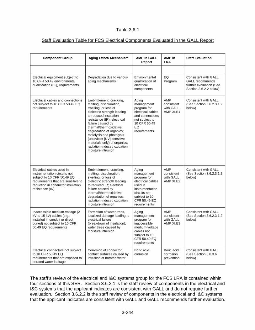
3-244
Table 3.6-1
Staff Evaluation Table for FCS Electrical Components Evaluated in the GALL Report
Component Group Aging Effect/ Mechanism AMP in GALLReport
AMP inLRA
Staff Evaluation
Electrical equipment subject to10 CFR 50.49 environmentalqualification (EQ) requirements
Degradation due to variousaging mechanisms
Environmentalqualification ofelectricalcomponents
EQProgram
Consistent with GALL.GALL recommendsfurther evaluation (SeeSection 3.6.2.2 below)
Electrical cables and connectionsnot subject to 10 CFR 50.49 EQrequirements
Embrittlement, cracking,melting, discoloration,swelling, or loss ofdielectric strength leadingto reduced insulationresistance (IR); electricalfailure caused bythermal/thermoxidativedegradation of organics;radiolysis and photolysis(ultraviolet [UV] sensitivematerials only) of organics;radiation-induced oxidation;moisture intrusion
Agingmanagementprogram forelectrical cablesand connectionsnot subject to10 CFR 50.49EQrequirements
AMPconsistentwith GALLAMP XI.E1
Consistent with GALL.(See Section 3.6.2.3.1.2below)
Electrical cables used ininstrumentation circuits not subject to 10 CFR 50.49 EQrequirements that are sensitive toreduction in conductor insulationresistance (IR)
Embrittlement, cracking,melting, discoloration,swelling, or loss ofdielectric strength leadingto reduced IR; electricalfailure caused bythermal/thermoxidativedegradation of organics; radiation-induced oxidation;moisture intrusion
Agingmanagementprogram forelectrical cablesused ininstrumentationcircuits notsubject to 10CFR 50.49 EQrequirements
AMPconsistentwith GALLAMP XI.E2
Consistent with GALL(See Section 3.6.2.3.1.2below)
Inaccessible medium-voltage (2kV to 15 kV) cables (e.g.,installed in conduit or directburied) not subject to 10 CFR50.49 EQ requirements
Formation of water trees,localized damage leading toelectrical failure(breakdown of insulation);water trees caused bymoisture intrusion
Agingmanagementprogram forinaccessiblemedium-voltagecables notsubject to 10CFR 50.49 EQrequirements
AMPconsistentwith GALLAMP XI.E3
Consistent with GALL (See Section 3.6.2.3.1.2below)
Electrical connectors not subjectto 10 CFR 50.49 EQrequirements that are exposed toborated water leakage
Corrosion of connectorcontact surfaces caused byintrusion of borated water
Boric acidcorrosion
Boric acidcorrosionprevention
Consistent with GALL (See Section 3.0.3.6below)
The staff’s review of the electrical and I&C systems group for the FCS LRA is contained withinfour sections of this SER. Section 3.6.2.1 is the staff review of components in the electrical andI&C systems that the applicant indicates are consistent with GALL and do not require furtherevaluation. Section 3.6.2.2 is the staff review of components in the electrical and I&C systemsthat the applicant indicates are consistent with GALL and GALL recommends further evaluation.

3-245
Section 3.6.2.3 is the staff evaluation of aging management programs that are specific to theelectrical and I&C components. Section 3.6.2.4 contains an evaluation of the adequacy ofaging management for components in each system in the electrical and I&C systems group.
3.6.2.1 Aging Management Evaluations in the GALL Report that Are Relied on forLicense Renewal, Which Do Not Require Further Evaluation
For component groups evaluated in GALL for which the applicant has claimed consistency withGALL, and for which GALL does not recommend further evaluation, the staff sampledcomponents in these groups during the AMR inspection to determine whether the plant-specificcomponents contained in these GALL component groups are bounded by the GALL evaluation. The staff also sampled component groups during the AMR inspection to determine whether theapplicant had properly identified those component groups in GALL that are not applicable to itsplant. The results of the staff’s AMR inspection can be found in AMR Inspection Report 50-285/03-07, dated March 20, 2003.
On the basis of its review of the inspection results, the staff finds that the applicant’s claim ofconsistency with GALL is acceptable, and that it is acceptable for the applicant to reference theinformation in the GALL Report for electrical and I&C components. Therefore, on this basis, thestaff concludes that the applicant has demonstrated that the components for which theapplicant claimed consistency with GALL will be adequately managed so that the intendedfunction(s) will be maintained consistent with the CLB for the period of extended operation, asrequired by 10 CFR 54.21(a)(3) and that the USAR Supplement provides an adequatesummary description of the programs and activities credited for managing the effects of agingfor the ESF system components for which the applicant claimed consistency with GALL, asrequired by 10 CFR 54.21(d).
3.6.2.2 Electrical Equipment Subject to Environmental Qualification
As stated in the SRP-LR, environmental qualification is a TLAA as defined in 10 CFR 54.3. TLAAs are required to be evaluated in accordance with 10 CFR 54.21(c)(1). The environmentalqualification TLAA is discussed in LRA Section 4.4. The staff reviewed the evaluation of thisTLAA separately in Section 4.4 of this SER, following the guidance in Section 4.4 of the SRP-LR.
3.6.2.3 Aging Management Programs for Electrical and I&C Components
In SER Section 3.6.2.1, the staff determined that the applicant’s AMRs and associated AMPswill adequately manage component aging in electrical and I&C systems. The staff thenreviewed specific electrical and I&C system components to ensure that they were properlyevaluated in the applicant’s AMR.
To perform its review, the staff reviewed the components listed in tables in LRA Sections 2.5.1-1 through 2.5.20-1 to determine whether the applicant had properly identified the applicableAMRs and AMPs needed to adequately manage the aging effects for the components. Thisportion of the staff review involved identification of the aging effects for each component,ensuring that each aging effect was evaluated using the appropriate AMR in Section 3, and thatmanagement of the aging effect was captured in the appropriate AMP. The results of the staff’sreview are provided below.

3-246
The staff also reviewed the USAR Supplement for the AMPs credited with managing aging inelectrical and I&C system components to determine whether the program descriptionsadequately describe the programs.
The applicant credits two AMPs to manage the aging effects associated with electrical and I&Ccomponents. The boric acid corrosion prevention program is credited with managing aging incomponents in other system groups (common AMPs) while the non-EQ AMP is credited withmanaging aging only for electrical and I&C components. The staff’s evaluation of the boric acidcorrosion prevention program is provided in Section 3.0.3.6 of this SER.
The staff’s evaluation of the non-EQ cable AMP is provided here.
3.6.2.3.1 Non-EQ Cable Aging Management Program
3.6.2.3.1.1 Summary of Technical Information in the Application
In LRA Section B.3.4, ”Non-EQ Cable Aging Management Program,” the applicant provides itsAMP to manage aging in electrical cables and connectors not subject to 10 CFR 50.49 and theelectrical cables used in instrumentation circuits not subject to 10 CFR 50.49. The LRA statesthat the FCS non-EQ cable AMP establishes a service life value for the non-EQ cable in asimilar fashion as the FCS EQ program establishes a qualified life for safety-related equipment. Non-EQ cable was purchased to the same requirements and specifications as that included inthe EQ program for the cable installed and qualified under the EQ program. Additionaltemperature and environmental data utilized to extend the qualified life of the EQ equipmentand cable will be utilized to analyze and establish a service life for the non-EQ cables. Theseanalyses are relied upon to predict the life expectancy of the non-EQ cables under the normaland abnormal plant operating conditions. Cables not capable of having a 60-year service lifewill be further analyzed using state of the art analytical techniques to determine if the servicelife can be further extended. Industry-accepted and regulatory-approved cable inspectiontechniques that provide aging related data, as well as state-of-the-art in-situ, non-destructivetesting of cable performance, and/or laboratory testing of cable to extend life, may also beconsidered should the aforementioned methodologies not succeed in extending the requiredservice life.
3.6.2.3.1.2 Staff Evaluation
The staff reviewed the applicant’s non-EQ cable AMP credited for the aging management ofinsulated cables and connections at FCS. The staff’s evaluation includes a review of the agingeffects considered. The staff reviewed this section of the LRA to determine whether theapplicant has demonstrated that the effects of aging on cables will be adequately managedduring the period of extended operation, as required by 10 CFR 54.21(a)(3). The staff alsoreviewed the USAR Supplement for this AMP to determine whether it provides an adequatesummary description of the program, as required by 10 CFR 54.21(d).
The staff noticed that although the applicant referenced GALL as an AMP, all the elements ofthe AMP were not consistent with GALL. Therefore, the staff was unclear how the proposedAMP will manage aging of electrical components that are within the scope of the licenserenewal and subject to an AMR, but that are not subject to 10 CFR 50.49 environmentalqualification requirements (including those used in instrument circuits as well as inaccessiblemedium voltage cables). In addition, for inaccessible medium-voltage (2 kV to 15 kV) cables(e.g., installed in conduit or direct buried) not subject to 10 CFR 50.49 EQ requirements, noaging program was proposed by the applicant. The LRA stated that modifications were made

3-247
to the duct banks for inaccessible non-EQ medium voltage cables to preclude moistureintrusion; therefore there is no aging effect requiring management. However, it was not clear tothe staff what periodic actions will be taken during the period of extended operation to assurethat the modifications made to prevent inaccessible non-EQ medium-voltage cables from beingexposed to significant moisture will remain intact. By letter dated October 11, 2002, the staffissued RAI B.3.4-1, requesting the applicant to clarify the following three items:
1. How will the non-EQ aging management program manage aging in accessible andinaccessible electrical cables and connections that are within the scope of licenserenewal and subject to an AMR, but are not subject to the environmental qualificationrequirements of 10 CFR 50.49 and that are exposed to adverse localized conditionscaused by radiation, temperature or moisture, such that the cables and connectors willperform their intended functions in accordance with the current licensing basis throughthe period of extended operation?
2. How will the non-EQ aging management program manage aging in accessible andinaccessible electrical cables and connectors that are within the scope of licenserenewal and subject to an AMR and are exposed to adverse localized conditions causedby radiation, temperature or moisture, and that are used in circuits with sensitive, low-level signals, but that are not subject to the environmental qualification requirements of10 CFR 50.49, such that the cables will perform their intended functions in accordancewith the current licensing basis through the period of extended operation?
3. How will the non-EQ aging management program manage aging in inaccessible
medium voltage cables that are within the scope of license renewal and subject to anAMR, and are exposed to adverse localized environments caused by moisture whileenergized, but are not subject to the environmental qualification requirements of 10 CFR50.49, such that the cables will perform their intended functions in accordance with thecurrent licensing basis through the period of extended operation?
In a letter dated December 19, 2002, the applicant responded to RAI B.3.4-1, stating that, fornon-EQ cables and connections within the scope of license renewal and subject to an agingmanagement review
1. Prior to period of extended operation, OPPD will implement a program and inspectionconsistent with that described in XI.E.1 of the GALL Report.
2. Prior to period of extended operation, OPPD will implement a program and inspectionconsistent with that described in XI.E.2 of the GALL Report.
3. In response to this item, the applicant stated that in 1994, during an inspection of thecable vault/manhole, it was discovered that moisture ingress around the manhole wascausing some of the conduits to corrode. A section of boat foam was added around theconduit nest to preclude water from seeping in through the manhole cover to furthercorrode the conduit. Additionally, the manhole was sealed.
Medium voltage cables (six shutdown circuits) are routed through the vault and into duct banksfrom the intake structure to the service building. Although medium voltage cables are routedthrough the duct banks, by design, they will not accumulate standing water; duct banks arepitched at a minimum of 1/8 inch per foot. The applicant stated that in 30 years, it has not hada cable failure, and committed to implementing a program and inspection consistent with that
3-248
described in XI.E3 of the GALL Report. The staff found the applicant’s response to RAI B.3.4-1satisfactory.
The staff reviewed the USAR Supplement for the non-EQ cable AMP as described in the LRAand found that the supplement did not provide an adequate description of the revised program,as required by 10 CFR 54.21(d). The AMP provided in the LRA reflected the program asoriginally envisioned by the applicant. As discussed above, the applicant has committed torevising the AMP to reflect the positions in GALL Report Sections XI.E1, XI.E2, and XI.E3. Asa result, the description of the AMP in the USAR Supplement must be revised to reflect thedescriptions of XI.E1, XI.E2, and XI.E3. The applicant was requested to submit to the staff arevised USAR Supplement that is consistent with the descriptions for GALL AMPs XI.E1, XI.E2,and XI.E3 and satisfies 10 CFR 54.21(d). This was identified as Open Item 3.6.2.3.1.2-1.
By letter dated July 7, 2003, the applicant submitted the following revised USAR SupplementSection A.2.15 description that supersedes the Section A.2.15 in the LRA.
A.2.15 Non-EQ Cable Aging Management Program
The FCS Non-EQ Cable Aging Management Program is a new program that provides agingmanagement of (1) non-environmentally qualified electrical cables and connections exposed to anadverse localized environment caused by heat, radiation, or moisture; (2) non-environmentallyqualified electrical cables used in instrumentation circuits that are sensitive to reduction in conductorinsulation resistance, and are exposed to an adverse localized environment caused by heat, radiation,or moisture; and (3) non-environmentally qualified inaccessible medium-voltage cables exposed toan adverse localized environment caused by moisture and voltage exposure.
Aging management is provided by the following actions:
1. Accessible electrical cables and connections installed in adverse localized environments willbe inspected prior to the period of extended operation and at least once every 10 years forcable and connector jacket surface anomalies, such as embrittlement, discoloration,cracking, swelling, or surface contamination.
2. Electrical cables used in circuits with sensitive, low-level signals, such as radiation monitoringand nuclear instrumentation, are tested as part of the instrumentation loop calibration at thenormal calibration frequency.
3. In-scope medium voltage cables exposed to significant moisture and significant voltage willbe tested prior to the period of extended operation and at least once every 10 years toprovide an indication of the condition of the conductor insulation. The test will be a state-of-the-art test at the time the test is performed.
This program considers the technical information and guidance provided in NUREG/CR-5643, IEEEStd. P1205, SAND96-0344, EPRI TR-109619, and EPRI TR-103834-P1-2.
The staff reviewed the above information and finds that the revised USAR Supplement providesan adequate summary description of the revised Non-EQ Aging Management Program and thatthe program is consistent with GALL Programs XI.E1, XI.E2, and XI.E3. Open Item 3.6.2.3.1.2-1 is closed.
3.6.2.3.1.3 Conclusion
On the basis of its review and inspection of the applicant’s program, including the applicant’scommitment to implement a program and inspection consistent with GALL, the staff finds thatthose portions of the program for which the applicant claims consistency with GALL will beconsistent with GALL. The staff also reviewed the USAR Supplement for this AMP and finds

3-249
that the USAR Supplement provides an adequate summary description of the program, asrequired by 10 CFR 54.21(d).
Therefore, on the basis of its review, the staff concludes that with the applicant’s commitment todevelop an AMP consistent with GALL AMPs XI.E1, XI.E2, and XI.E3, the applicant hasdemonstrated that the non-EQ cable program will effectively manage aging in the componentsfor which this program is credited, so that the intended functions of the associated componentsand systems will be maintained consistent with the CLB for the period of extended operation, asrequired by 10 CFR 54.21(a)(3).
3.6.2.4 Aging Management Review of Plant-Specific Electrical Components
In this section of the SER, the staff presents its review of the applicant’s AMRs for specificelectrical components. To perform its evaluation, the staff reviewed the components listed inLRA Tables 2.5.1-1, 2.5.2-1, and 2.5.20-1, to determine whether the applicant properlyidentified the applicable aging effects and AMPs needed to adequately manage these agingeffects. This portion of the staff’s review involved identification of the aging effects for eachcomponent, ensuring that each aging effect was evaluated in the appropriate LRA AMR table inSection 3, and that management of the aging effect was captured in the appropriate AMP.
The results of the staff’s review are provided below.
3.6.2.4.1 Cables and Connectors
3.6.2.4.1.1 Summary of Technical Information in the Application
The AMR results for cables and connectors are presented in LRA Table 3.6-1. All electrical andI&C components within the scope of license renewal and subject to an AMR were addressed inthe GALL Report. The applicant used the GALL Report format to present its AMR of electricaland I&C components in LRA Table 3.6-1.
As described in LRA Section 2.5.1, cables and connectors provide electrical energy (eithercontinuously or intermittently) to power various equipment and components throughout theplant. Cables and connectors associated with the EQ program are addressed either as short-lived and periodically replaced, or as long-lived TLAAs. As such, they are not included in theset of cables and connectors requiring additional aging management.
Aging Effects
The LRA identifies the following aging effects for cables and connectors:
• degradation due to various aging mechanisms• embrittlement, cracking, melting, discoloration, swelling, or loss of dielectric strength
leading to reduced insulation resistance (IR)• electrical failure caused by thermal/thermoxidative degradation of organics• radiolysis and photolysis (ultraviolet-sensitive materials only) of organics• radiation-induced oxidation• moisture intrusion• formation of water trees; localized damage leading to electrical failure (breakdown of
insulation) caused by moisture intrusion and water trees• corrosion of connector contact surfaces caused by intrusion of borated water

3-250
The applicant credited the following AMPs and TLAA with managing the identified aging effectsfor cables and connectors:
• Boric Acid Corrosion Prevention Program (B.2.1)• Non-EQ Cable Aging Management Program (B.3.4)• EQ TLAA
A description of the AMPs is provided in Appendix B of the LRA. The EQ TLAA is described inLRA Section 4.4.
3.6.2.4.1.2 Staff Evaluation
In addition to LRA Section 3.6, the staff reviewed the pertinent information in LRA Section2.5.1, the applicable AMP descriptions provided in LRA Appendix B, and the EQ TLAA, todetermine whether the aging effects associated with cables and connectors have been properlyidentified and will be adequately managed during the period of extended operation, as requiredby 10 CFR 54.21(a)(3). The staff also reviewed the USAR Supplements for the AMPs creditedwith managing aging in cables and connectors, as well as the USAR Supplement that describesthe TLAA, to determine whether they provide adequate summary descriptions of the programsand TLAA, as required by 10 CFR 54.21(d).
This section of the SER provides the staff’s evaluation of the applicant’s AMRs for the agingeffects and the appropriateness of the programs credited for the aging management of cablesand connectors at FCS. The staff’s evaluation includes a review of the aging effectsconsidered and the basis for the applicant’s elimination of certain aging effects. In addition, thestaff has evaluated the appropriateness of the AMPs that are credited for managing theidentified aging effects for cables and connectors.
Aging Effects
As discussed above, the applicant identified the following aging effects for electrical and I&Ccomponents at FCS:
• degradation due to various aging mechanisms• embrittlement, cracking, melting, discoloration, swelling, or loss of dielectric strength
leading to reduced insulation resistance (IR)• electrical failure caused by thermal/thermoxidative degradation of organics• radiolysis and photolysis (ultraviolet-sensitive materials only) of organics• radiation-induced oxidation• moisture intrusion• formation of water trees; localized damage leading to electrical failure (breakdown of
insulation) caused by moisture intrusion and water trees• corrosion of connector contact surfaces caused by intrusion of borated water
The staff reviewed the information in LRA Table 3.6-1 for cables and connectors. On the basisof its review, the staff concludes that the aging effects identified for the subject components areconsistent with the aging effects evaluated in the GALL Report and, therefore, are acceptable.
The staff also reviewed the applicant’s response to the staff’s RAI, discussed below.

3-251
For inaccessible medium-voltage (2 kV - 15 kV) cables (e.g., installed in conduit or directburied) not subject to EQ requirements, LRA Table 3.6-1, Item 3.6.1.04, states thatmodifications were made to the duct banks to preclude moisture intrusion and, therefore, thereare no aging effects requiring management. It was not clear to the staff what actions will betaken to assure that the modifications made to prevent inaccessible non-EQ medium-voltagecables from being exposed to significant moisture will be maintained during the period ofextended operation. By letter dated October 11, 2002, the staff issued RAI 3.6-1, requestingthe applicant to provide a description of the program that will assure that the modifications aremaintained to prevent water intrusion into the duct banks, and to provide a description of theAMP that will be relied on for inaccessible medium-voltage cables installed in conduit, cabletrenches, cable troughs, underground vaults, or direct buried installations.
By letter dated December 19, 2002, the applicant responded to RAI 3.6-1 by noting that theinformation requested by the staff could be found in the applicant’s responses to RAIs 2.5-1and B.3.4-1, both of which were provided in the same response letter.
In its response to RAI 2.5-1, the applicant stated that there are no medium-voltage cables in thesubstation switchyard associated with station blackout (SBO). Medium voltage SBO cables inthe plant have been addressed as part of the cable commodity group, and include cablesassociated with the 4160 VAC system. Low-voltage (typically 120 V) cable is located in troughsand duct banks. High-voltage cable is located overhead on towers (single phase). Thearrangement of the duct banks is such that they are pitched/sloped at no less than 1/8 in perfoot to maintain cable out of long-term water immersion by preventing standing water.
In its response to Part 3 of RAI B.3.4-1 concerning aging management of inaccessible medium-voltage electrical cables exposed to adverse localized environments caused by moisture whileenergized, but are not within the EQ program, the applicant stated that in 1994, during aninspection of a cable vault/manhole containing these cables, it was discovered that moisturehad entered through the manhole and was causing some of the cable to corrode. To correctthe problem, the applicant applied boat foam around the conduit to preclude water from seepingin through the manhole cover. Additionally, the manhole was sealed. Six medium-voltage safeshutdown circuits are routed through the vault and into duct banks from the intake structure tothe service building. Although medium-voltage cables are routed through the duct banks, theduct banks are designed to prevent the accumulation of standing water. The duct banks arepitched at a minimum 1/8 inches per foot. In 30 years, the applicant has not had a cable failure;however, to ensure that the cables susceptible to potentially wetted condition will notdeteriorate, the applicant committed to implementing a program and inspection consistent withthat described in Section XI.E3 of the GALL Report.
On the basis of the applicant’s responses contained in RAIs 2.5-1 and B.3.4-1, the staff findsthat the applicant has identified the applicable aging effects for the cables and connectors atFCS.
Aging Management Programs
The applicant credited the following AMPs and TLAA for managing the aging effects for cablesand connectors:
• Boric Acid Corrosion Prevention Program (3.0.3.6)• Non-EQ Cable Aging Management Program (3.6.2.3.1)• EQ TLAA
3-252
The boric acid corrosion program is credited for managing the aging effects of components inseveral systems and structures and, therefore, is considered a common AMP. The staff hasevaluated this common AMP and found it to be acceptable for managing the aging effectsidentified for this system. This AMP is evaluated in Section 3.0.3.6 of this SER.
With regard to the non-EQ AMP provided in LRA Section B.3.4, the staff was concerned thatthe applicant’s AMP was not consistent with GALL AMPs XI.E1, XI.E2, and XI.E3, whichprovide guidance on the management of non-EQ cables within the scope of license renewaland subject to an AMR. By letter dated October 11, 2002, the staff issued RAI B.3.4-1,requesting the applicant to describe how the non-EQ AMP will manage the aging effectsassociated with non-EQ cables.
By letter dated December 19, 2002, the applicant responded to RAI B.3.4-1, by committing todevelop, prior to the period of extended operation, AMPs that are consistent with GALL AMPsXI.E1, XI.E2, and XI.E3. The staff finds this commitment acceptable because implementationof AMPs consistent with the GALL AMPs will ensure that non-EQ cables within the scope oflicense renewal and subject to an AMR, and that experience the subject aging effects, will beadequately managed during the period of extended operation. The staff’s review of this issuecan be found in Section 3.6.2.3.1.2 of this SER.
Aging management of environmentally-qualified cables and connectors will continue to beperformed through the applicant’s EQ program, which is identified as a TLAA for licenserenewal. The staff’s evaluation of the applicant’s EQ TLAA can be found in Section 4.4 of thisSER.
On the basis of its review, including the applicant’s responses to the staff’s RAIs, the staffconcludes that the above identified AMPs and TLAA will effectively manage the aging effectsassociated with cables and connectors.
The staff also reviewed the applicable USAR Supplement program descriptions and concludesthat the USAR Supplement provides an adequate program description of the AMPs credited formanaging aging in cables and connectors to satisfy 10 CFR 54.21(d).
3.6.2.4.1.3 Conclusion
On the basis of its review, the staff concludes that the applicant has adequately identified theaging effects and, with the fulfillment of the commitments identified in Section 3.6.2.4.1.2above, will have adequate AMPs and TLAAs for managing the aging effects for cables andconnectors, such that the component intended functions will be maintained consistent with theCLB for the period of extended operation, as required by 10 CFR 54.21(a)(3).
The staff also reviewed the applicable USAR Supplement program descriptions and concludesthat the USAR Supplement provides an adequate program description of the AMPs credited formanaging aging in cables and connectors to satisfy 10 CFR 54.21(d).
3.6.2.4.2 Containment Electrical Penetrations
3.6.2.4.2.1 Summary of Technical Information in the Application
The AMR results for containment electrical penetrations are presented in LRA Table 3.6-1. Allelectrical and I&C components within the scope of license renewal and subject to an AMR wereaddressed in the GALL Report. The applicant used the GALL Report format to present its AMRof electrical and I&C components in LRA Table 3.6-1.

3-253
As described in LRA Section 2.5.4, electrical penetrations are containment boundarycomponents that provide electrical energy across the containment boundary (eithercontinuously or intermittently) to power various equipment and components throughout theplant. The electrical penetration provides an electrical connection between two sections of theelectrical/I&C circuit. The pigtail at each end of the penetration is connected to the field cable invarious ways. The boundary for the electrical penetrations includes the pigtail cable. Penetrations associated with the EQ program are addressed either as short-lived andperiodically replaced, or as long-lived TLAAs.
Aging Effects
The LRA identifies the following aging effects for containment electrical penetrations:
• degradation due to various aging mechanisms• embrittlement, cracking, melting, discoloration, swelling, or loss of dielectric strength
leading to reduced insulation resistance (IR)• electrical failure caused by thermal/thermoxidative degradation of organics• radiolysis and photolysis (ultraviolet-sensitive materials only) of organics• radiation-induced oxidation• moisture intrusion• corrosion of connector contact surfaces caused by intrusion of borated water• loss of material due to corrosion for penetration sleeves, penetration bellows, and
dissimilar metal welds
The applicant credited the following AMPs and TLAA with managing the identified aging effectsfor containment electrical penetrations:
• Containment ISI Program (B.1.3)• Containment Leak Rate Program (B.1.4)• Boric Acid Corrosion Prevention Program (B.2.1)• Non-EQ Cable Aging Management Program (B.3.4)• EQ TLAA
A description of the AMPs is provided in Appendix B of the LRA. The EQ TLAA is described inLRA Section 4.4.
3.6.2.4.2.2 Staff Evaluation
In addition to LRA Section 3.6, the staff reviewed the pertinent information in LRA Section2.5.2, the applicable AMP descriptions provided in LRA Appendix B, and the EQ TLAA, todetermine whether the aging effects associated with containment electrical penetrations havebeen properly identified and will be adequately managed during the period of extendedoperation, as required by 10 CFR 54.21(a)(3). The staff also reviewed the USAR Supplementsfor the AMPs credited with managing aging in cables and connectors, as well as the USARSupplement that describes the TLAA, to determine whether they provide adequate summarydescriptions of the programs and TLAA, as required by 10 CFR 54.21(d).
This section of the SER provides the staff’s evaluation of the applicant’s AMRs for the agingeffects and the appropriateness of the programs credited for the aging management ofcontainment electrical penetrations at FCS. The staff’s evaluation includes a review of theaging effects considered. In addition, the staff has evaluated the appropriateness of the AMPsthat are credited for managing the identified aging effects for containment electricalpenetrations.

3-254
Aging Effects
The LRA identifies the following aging effects for the containment electrical penetrations:
• degradation due to various aging mechanisms• embrittlement, cracking, melting, discoloration, swelling, or loss of dielectric strength
leading to reduced insulation resistance (IR)• electrical failure caused by thermal/thermoxidative degradation of organics• radiolysis and photolysis (ultraviolet-sensitive materials only) of organics• radiation-induced oxidation• moisture intrusion• corrosion of connector contact surfaces caused by intrusion of borated water• loss of material due to corrosion for penetration sleeves, penetration bellows, and
dissimilar metal welds
In LRA Table 2.5.2-1, the applicant identifies the containment electrical penetrations ascomponents that are within the scope of license renewal and subject to AMR. In this table, theapplicant identifies several links, including 3.6.1.01 and 3.6.1.02 in LRA Table 3.6-1. The staffbelieves that the electrical penetrations may include low-level instrument cable pigtails, whichrequire aging management identified in LRA Table 3.6-1, link 3.6.1.03. By letter datedFebruary 20, 2003, the staff issued POI-12, requesting the applicant to clarify whether low-levelinstrument cable pigtails are included in the containment electrical penetrations and whetherthey will be managed by the non-EQ cable AMP. By letter dated March 14, 2003, the applicantresponded to POI-12 by stating that LRA Table 2.5.2-1 has been revised to include thecontainment type “Instrument Cable Pigtails,” that have an intended function of “ElectricalContinuity,” and are linked to LRA AMR Item 3.6.1.03. These components will, therefore, bemanaged for aging by the non-EQ cable AMP. A revision to LRA Table 2.5.2-1 was included inthe applicant’s response. The staff finds this acceptable, and POI-12 is resolved.
On the basis of its review, including the applicant’s response to POI-12, the staff finds that theapplicant has identified the applicable aging effects for the containment electrical penetrationsat FCS.
Aging Management Programs
The applicant credited the following AMPs and TLAA for managing the aging effects forcontainment electrical penetrations:
• Containment ISI Program (3.0.3.3)• Boric Acid Corrosion Prevention Program (3.0.3.6)• Containment Leak Rate Program (3.5.2.3.1)• Non-EQ Cable Aging Management Program (3.6.2.3.1)• EQ TLAA
The containment ISI and boric acid corrosion programs are credited for managing aging effectsof components in several systems and structures and, therefore, are considered commonAMPs. The staff has evaluated these common AMPs and found them to be acceptable formanaging the aging effects identified for this system. These AMPs are evaluated in Sections3.0.3.3 and 3.0.3.6 of this SER, respectively.
As discussed in Section 3.6.2.3.1.2 above, the applicant committed to develop, prior to theperiod of extended operation, an AMP to manage non-EQ electrical components consistent withGALL AMPs XI.E1, XI.E2, and XI.E3. The staff considers this commitment adequate to ensure

3-255
that the containment electrical penetrations will be adequately managed during the period ofextended operation.
Aging management of environmentally-qualified containment electrical penetrations willcontinue to be performed through the applicant’s EQ program, which is identified as a TLAA forlicense renewal. The staff’s evaluation of the applicant’s EQ TLAA can be found in Section 4.4of this SER.
On the basis of its review, the staff concludes that the above identified AMPs and TLAA willeffectively manage the aging effects associated with the containment electrical penetrations.
The staff also reviewed the applicable USAR Supplement program descriptions and concludesthat the USAR Supplement provides an adequate program description of the AMPs credited formanaging aging in containment electrical penetrations to satisfy 10 CFR 54.21(d).
3.6.2.4.2.3 Conclusions
On the basis of its review, the staff concludes that the applicant has adequately identified theaging effects, and, with the fulfillment of the commitments identified in Section 3.6.2.4.2.2above, will have adequate AMPs and TLAAs for managing the aging effects for containmentelectrical penetrations, such that the component intended functions will be maintainedconsistent with the CLB for the period of extended operation, as required by 10 CFR54.21(a)(3).
The staff also reviewed the applicable USAR Supplement program descriptions and concludesthat the USAR Supplement provides an adequate program description of the AMPs credited formanaging aging in containment electrical penetrations to satisfy 10 CFR 54.21(d).
3.6.2.4.3 Bus Bars
3.6.2.4.3.1 Summary of Technical Information in the Application
Electrical buses electrically connect specified sections of an electrical circuit to deliver voltageor current (either continuously or intermittently) to various equipment and componentsthroughout the plant. The standoffs support the electrical bus bars.
In LRA Section 2.5.20, the applicant states that there are no electrical buses or associatedstandoffs within the scope of license renewal that are included in the 10 CFR 50.49 program.
Aging Effects
In LRA Section 2.5.20, the applicant has identified the bus bars and standoffs as passive, long-lived components that are within the scope of the license renewal and subject to an AMR, andhas concluded that these components have no aging effects that require management. Theapplicant’s AMR results for these items show that no aging effects requiring management wereidentified for this group.
Aging Management Programs
Because the applicant did not identify any aging effects requiring management for the bus barsand bus bar standoffs, no AMPs are credited for managing aging.
3-256
3.6.2.4.3.2 Staff Evaluation
The staff reviewed the AMR results for the aging management of bus bars and standoffs atFCS to determine whether the applicant has demonstrated that the effects of aging on bus barsand standoffs will be adequately managed during the period of extended operation, as requiredby 10 CFR 54.21(a)(3).
The bus bars are a pre-assembled raceway design, with bus bars mounted on insulatedsupports (standoffs). The intended function of the standoffs is to support the electrical busbars.
Aging Effects
The LRA stated that there are no aging effects requiring management for the electrical bus barsand bus bar standoffs. As discussed in Section 2.5.2.5.2 of this SER, the staff issued POI-6(b)requesting the applicant to provide information on the components’ materials and environments,along with the basis for concluding that these components have no plausible aging effects. Byletter dated March 14, 2003, the applicant responded to POI-6(b), stating the following:
The bus bar materials are copper and aluminum; their environment is in indoor air and outdoor air.In accordance with EPRI TR-114882, Non-Class1 Mechanical Implementation Guideline andMechanical Tools, Revision 2, 1999, no aging effects were identified for aluminum, aluminum alloys,copper, or copper alloys (brass, bronze) in an indoor or outdoor air environment.
The stand offs include fiberglass reinforced polyester resin and porcelain materials that are in ambientair external environment and are not continuously wetted. Internal environments are not applicable.
Table 7-17 of EPRI NP-1558, A Review of Equipment Aging Theory and Technology, lists thecontinuous use temperature of plastics. The continuous use temperature(a) listed for polyester with40% glass content is 266 �F(b) (compared with the bounding temperature value of 122 �F). Applyingthe Arrhenius methodology, it is clear that fiberglass reinforced polyester is acceptable. Figure C-2of EPRI NP-1558 contains the relative radiation stability of thermosetting resins. The threshold forgamma radiation for polyester (glass filled) is 1,000,000,000 Rads (compared with the bounding 60-year radiation dose of less than 1,000 Rads).
(a) Continuous use temperatures were determined as the temperatures corresponding to100,000 hours (11.4 years) on the Arrhenius curve of the material for an endpoint of 50%reduction in tensile strength.
(b) Based on retention of tensile strength taken at 500 degrees F. On the basis of its review of the applicant’s response to POI-6(b), the staff was concerned thatthe applicant may not have considered all the aging effects of the bus bars/ducts. The staffdiscussed this issue with the applicant, pointing out that industry experience has indicatedseveral problems with the bus bar/duct, such as loosening of splice plate bolts, degradation ofNoryl insulation, presence of moisture or debris, oxidation of aluminum electrical connections,and corrosion of metallic components. On the basis of this experience, the staff requested thatthe applicant provide a description of the AMP used to detect the above aging effects, orprovide justification why such a program is not needed. This was identified as Open Item3.6.2.4.3.2-1.
By letter dated July 7, 2003, the applicant responded to Open Item 3.6.2.4.3.2-1, stating thatwhen scoping and screening were performed for bus bars at FCS, as a conservative measure,all bus bars were included within the scope of license renewal, with the exception of thoseassociated with SBO. SBO beyond the plant boundary was added later in response to a staffRAI and the NRC ISG on SBO. All of the in-plant bus bars are inside the enclosure of an active

3-257
component, such as switchgear, power supplies, etc., and are considered to be piece parts ofthe larger assembly. Per 10 CFR 54.21, OPPD considers them not to be subject to an AMR.
The applicant stated that the SBO restoration buses (nonsegregated and iso-phase) are fedfrom the 161 Kv and 345 Kv transmission lines from the switchyard primary side of thetransformers (auxiliary and main) and connect to the plant from the secondary side of thetransformers by bus work (non-segregated from the auxiliary transformers and isophase fromthe main). The isophase bus, which is an aluminum tube contained in a tube-like aluminumenclosure, connects the main transformer to the main generator and to the unit auxiliarytransformers. The isophase bus is continuously air-cooled and no moisture accumulation hasever been observed. The isophase bus connects from the main to the auxiliary transformerswith bolted connections. The connections of the buses to the transformers are inspected andgreased periodically in accordance with OPPD Substation Maintenance Departmentprocedures. The inspections are performed on a “train outage schedule” (i.e., in one refuelingoutage, one bus is inspected and during the next outage, the other bus is inspected).
The auxiliary transformers utilize nonsegregated copper buses to connect to the 4160-voltdistribution system. Use of flexible copper buses minimizes the effects of vibration from enddevices. The connections of the buses to the transformers are inspected and greasedperiodically in accordance with OPPD Substation Maintenance Department procedures. Thenonsegregated bus work is insulated. However, past inspections of this area revealed peelingor flaking of the insulation (inspections were performed during the early- to mid- 1970s, prior toimplementation of the current Corrective Action Program). To preclude further degradation,OPPD taped a good portion of the non-segregated buses, including the affected areas. Thetaping was done with Bishops High Voltage tape, with the ends taped off with Scotch 88 tape. OPPD inspects these buses on a "train outage schedule.” These buses are inspected using aplant maintenance procedure which inspects the bus and the switchgear cubicles associatedwith that bus.
The bus bars credited in the SBO restoration path are all connected to the auxiliarytransformers by bolted connections. The aging of the bolted connections is managed throughimplementation of the OPPD Periodic Surveillance and Preventive Maintenance Program. TheOPPD substation maintenance crew periodically inspects all bolted connections. The torquevalues of the bolted connections are also periodically checked. Routine inspection and cleaningof the buses by Substation Maintenance Department and FCS Maintenance Department crewspreclude the buildup of any dirt or debris or the existence of loose bolting.
The description of the Periodic Surveillance and Preventive Maintenance Program in LRASection A.2.18 (the USAR Supplement) is not at the level of detail that warrants mention of busbar aging management, therefore, this section has not been revised. However, OPPD hasrevised the Periodic Surveillance and Preventive Maintenance Program description in LRASection B.2.7 to include Substation–SBO Restoration in the program scope. The program’sactivities also check bus connectors for loss of torque and degradation of insulation wrap. Therevised LRA Section B.2.7 is provided below.
B.2.7 Periodic Surveillance And Preventive Maintenance (PM) Program
The stated purpose of the PM program is to prevent or minimize equipment breakdown and tomaintain equipment in a condition that will enable it to perform its normal and emergency functions.The program and the site administrative control processes provide for a systematic approach inestablishing the method, frequency, acceptance criteria, and documentation of results.
The FCS Periodic Surveillance and Preventive Maintenance Program consists of periodic inspectionsand tests that are relied on to manage aging for system and structural components and that are notevaluated as part of the other aging management programs addressed in this appendix. The

3-258
preventive maintenance and surveillance testing activities are implemented through periodic workorders that provide for assurance of functionality of the components by confirmation of integrity ofapplicable parameters.
EVALUATION AND TECHNICAL BASIS
(1) Scope of Program:
The FCS Periodic Surveillance and Preventive Maintenance Program provides for periodic inspectionand testing of components in the following systems and structures.
� Auxiliary Building � Emergency Diesel Generators� Auxiliary Building HVAC � Fire Protection� Auxiliary Feedwater � Fuel Handling Equipment/Heavy Load Cranes � Chemical and Volume Control � Intake Structure� Component Cooling � Liquid Waste Disposal� Containment � Duct Banks� Containment HVAC � Reactor Coolant� Control Room HVAC and Toxic � Safety Injection and Containment Spray
Gas Monitoring � Ventilating Air� Diesel Generator Lube Oil � Substation – SBO Restoration� Containment Penetration, and System Interface Components for Non-CQE Systems
(2) Preventive Actions:
The Periodic Surveillance and Preventive Maintenance Program includes periodic refurbishment orreplacement of components, which could be considered to be preventive or mitigative actions. Theinspections and testing to identify component aging degradation effects do not constitute preventiveactions in the context of this element.
(3) Parameters Monitored or Inspected:
Inspection and testing activities monitor parameters including surface condition, loss of material,presence of corrosion products, signs of cracking and presence of water in oil samples.
(4) Detection of Aging Effects:
Preventive maintenance and surveillance testing activities provide for periodic component inspectionsand testing to detect the following aging effects and mechanisms:
� Change in Material Properties � Loss of Material – General Corrosion � Cracking � Loss of Material - Pitting Corrosion
� Fouling � Loss of Material - Pitting/Crevice/Gen. � Degradation of insulation wrap Corrosion� Loss of Material � Loss of Material – Wear� Loss of Material – Crevice Corrosion � Separation
� Loss of Material – Fretting � Loss of Torque
The extent and schedule of the inspections and testing assures detection of component degradationprior to the loss of their intended functions. Established techniques such as visual inspections and dyepenetrant testing are used.
(5) Monitoring and Trending:
Preventive maintenance and surveillance testing activities provide for monitoring and trending of agingdegradation. Inspection intervals are established such that they provide for timely detection ofcomponent degradation. Inspection intervals are dependent on the component material andenvironment and take into consideration industry and plant-specific operating experience andmanufacturers’ recommendations.
The program includes provisions for monitoring and trending with the stated intent of identifyingpotential failures or degradation and making adjustments to ensure components remain capable ofperforming their functions. PM review and update guidelines are provided that include adjustment ofPM task and frequency based on the as-found results of previous performance of the PM. In particular,
3-259
responsible system engineers are required to periodically review the results of preventive maintenanceand recommend changes based on these reviews. The program includes guidance to assist thesystem engineers in achieving efficient and effective trending.
(6) Acceptance Criteria:
Periodic Surveillance and Preventive Maintenance Program acceptance criteria are defined in thespecific inspection and testing procedures. They confirm component integrity by verifying the absenceof the aging effect or by comparing applicable parameters to limits based on the applicable intendedfunction(s) as established by the plant design basis.
(7) Corrective Actions:
Identified deviations are evaluated within the FCS corrective action process, which includes provisionsfor root cause determinations and corrective actions to prevent recurrence as dictated by thesignificance of the deviation. The FCS corrective action process is in accordance with 10 CFR 50Appendix B.
(8) Confirmation Process:
The FCS corrective action process is in accordance with 10 CFR 50 Appendix B and includes:
� Reviews to assure that proposed actions are adequate;� Tracking and reporting of open corrective actions; and� For root cause determinations, reviews of corrective action effectiveness.
(9) Administrative Controls:
All credited aging management activities are subject to the FCS administrative controls process, whichis in accordance with 10 CFR 50 Appendix B and requires formal reviews and approvals.
(10) Operating Experience:
Periodic surveillance and preventive maintenance activities have been in place at FCS since the plantbegan operation. These activities have a demonstrated history of detecting damaged and degradedcomponents and causing their repair or replacement in accordance with the site corrective actionprocess. With few exceptions, age-related degradation adverse to component intended functions wasdiscovered and corrective actions were taken prior to loss of intended function.
Conclusion:
The Periodic Surveillance and Preventive Maintenance Program assures that various aging effectsare managed for a wide range of components at FCS. Based on the program structure andadministrative processes and FCS operating experience, there is reasonable assurance that thecredited inspection and testing activities of the Periodic Surveillance and Preventive MaintenanceProgram will continue to adequately manage the identified aging effects of the applicable componentsso that the intended functions will be maintained consistent with the current licensing basis for theperiod of extended operation.
The staff reviewed the applicant’s response to Open Item 3.6.2.4.3.2-1, including the revisedaging management program description, and finds that the applicant has provided anacceptable aging management program to manage the aging effects associated with the busbars/ducts. On this basis, Open Item 3.6.2.4.3.2-1 is closed.
The staff also reviewed the revised USAR Supplement for the AMP and concludes that itprovides an adequate description of the program, as required by 10 CFR 54.21(d).
3.6.2.4.3.3 Conclusions
On the basis of its review, the staff concludes that the applicant has adequately identified theaging effects for the bus bars and will have adequate AMPs and TLAAs for managing the agingeffects for bus bars, such that the component intended functions will be maintained consistent

3-260
with the CLB for the period of extended operation, as required by 10 CFR 54.21(a)(3).
The staff also concludes that the USAR Supplement provides an adequate program descriptionof the AMPs credited for managing aging in bus bars to satisfy 10 CFR 54.21(d).
3.6.2.4.4 Aging Management of SBO Components
3.6.2.4.4.1 Summary of Technical Information in the Application
The staff found that the screening results in Section 2.5 did not include any offsite powersystem structures or components related to the recovery of offsite power from an SBO event. 10 CFR 54.4(a)(3) requires that, “all systems, structures, and components relied on in safetyanalyses or plant evaluations to perform a function that demonstrates compliance with theCommission regulation for SBO (10 CFR 50.63) be included within the scope of licenserenewal.” The function of the offsite power system with the SBO rule is, therefore, to provide ameans of recovering from the SBO. This meets the criteria within license renewal 10 CFR54.4(a)(3) as a system that performs a function that demonstrates compliance with theCommission’s regulations on SBO. 10 CFR 54.4(a)(3) also requires that applicable offsitepower system structures and components required for compliance with the SBO rule should beincluded within the scope of license renewal and subject to an AMR, or additional justificationfor their exclusion should be provided.
3.6.2.4.4.2 Staff Evaluation
In a letter dated October 11, 2002, the staff issued RAI 2.5-1 regarding the scoping andscreening of SSCs which are required to comply with the SBO rule. Specifically, the staffrequested the applicant to clarify why switchyard systems were not relied upon in safetyanalyses to perform a function in the recovery from SBO. The applicant responded to RAI 2.5-1 by letter dated December 19, 2002, stating that it will revise the license renewaldocumentation to comply with the NRC ISG-02 on SBO.
The applicant identified the following passive, long-lived electrical components comprising theoffsite power system that are within the scope of license renewal and subject to an AMR:
• high voltage bus work/duct• aluminum conductor, steel reinforced (ACSR) transmission cables• insulators associated with the transmission conductors• transmission towers and supports• non-EQ cables (4 kV and 600 V)• 125 volt (120 Vac)control cables
The staff reviewed the applicant’s AMR results for the electrical components for SBOrestoration system components that were provided in response to RAI 2.5-1. The applicant’sAMR results for the electrical components for external environment are shown in Table 2 of theapplicant’s response to RAI 2.5-1. This table also refers to plant-specific programs that havebeen credited for aging management of the SBO restoration system components. However,several SBO components (high voltage bus work/duct, ACSR transmission cables andinsulators associated with the transmission conductors) are not identified in this table asrequiring an AMR. Therefore, it was not clear to the staff whether these components are withinthe scope of license renewal and subject to an AMR. By letter dated February 20, 2003, thestaff issued POI-6(a) requesting the applicant to clarify whether these components are withinscope and subject to an AMR.

3-261
By letter dated March 14, 2003, the applicant responded to POI-6(a) by providing the requestedinformation. The applicant has also provided the associated aging management information toallow the staff to determine whether the components will be adequately managed during theperiod of extended operation. Specifically, the applicant responded to POI-6(a) by stating that:
The high-voltage aluminum conductor is steel reinforced (ACSR) transmission cable and is consideredwithin the scope of license renewal for SBO. In accordance with EPRI TR-114882, “Non-Class 1Mechanical Implementation Guideline and Mechanical Tools,” Rev. 2, 1999, no aging effects wereidentified for aluminum, aluminum alloys, copper, or copper alloys (brass, bronze) in an indoor oroutdoor air environment. Transmission conductor vibration would be caused by wind loading. Windloading that can cause a transmission line and insulators to vibrate is considered in the designinstallation. Loss of material (wear) and fatigue that could be caused by transmission conductorvibration or sway are not aging effects requiring management of the period of extended operation atFCS. A review of internal and external operating experience has not identified any aging effectsrequiring management.
The insulators associated with the transmission conductors are made of porcelain and are within thescope of license renewal. Aging effects that are considered are buildup of surface contaminants andloss of material due to vibration (wear). As indicated above, (transmission line vibration), vibration dueto wind loading is a design consideration and not considered an aging effect requiring management. Buildup of surface contaminants (i.e., dust, dirt, etc.) can occur, however, it is gradual and frequentlywashed away by rain, consequently the buildup of surface contaminants is not significant andtherefore not an aging effect requiring management at Fort Calhoun. Information notices (INs)applicable to insulator contamination (IN 93-95) relate to a loss of power due to salt buildup. FortCalhoun is not located in an area of any salt concentration (Nebraska) and, therefore does notconsider this IN applicable. On the basis of the above, it has been determined that the porcelaininsulators in outside air at Fort Calhoun are not subject to any aging effects requiring management. The arresters associated with the offsite power system, although within the SBO boundary, do nothave any intended functions associated with license renewal, and are eliminated from the scope oflicense renewal as active components in accordance with NEI 95-10.
The isolated phase bus duct (i.e., isophase or 22 KV bus duct) encloses bus work that connects themain generator output to the main transformer. It is not related to the underground bus duct that maycarry low voltage power, control, and instrumentation wiring. The buswork has no AERM. Theenclosures supports for the isophase bus are identified in the LRA and assigned to the structuresmonitoring program for external environment. There is no AERM for internal environment.
The 125 volt dc and 120 volt ac control and instrumentation cables that are associated with breakercontrols and instrumentation within the SBO Restoration System have been considered in the scopeof License Renewal for SBO. Under non-EQ cables, all cables are subject to the non-EQ cable AMR.All non-EQ cable was identified in, and managed by, the non-EQ cable aging management program(B.3.4).
On the basis of the information provided in response to POI-6(a), the staff concludes that theapplicant has provided the associated aging management information to allow the staff todetermine whether the components will be adequately managed during the period of extendedoperation. However, the basis for the applicant’s assertion that bus bars/ducts and high voltageACSR transmission conductors have no aging effects is not clear to the staff. The staffdiscussed the issues with the applicant, requesting the applicant to clearly describe how theconnection from both SBO recovery paths are made, and to discuss the connection path up toand beyond the main transformer.
Also, as discussed in Section 3.6.2.4.3.2 of this SER, the staff pointed out that industryexperience has identified several problems with the bus bars/ducts. The staff’s review of busbars/ducts can be found in Section 3.6.2.4.1.2 of this SER. In addition, the aging effect for thetransmission ACSR conductor is loss of conductor strength and vibration. The applicant hasaddressed the vibration and the aluminum portion of the conductor, but did not address thesteel portion. The most prevalent mechanism contributing to loss of conductor strength iscorrosion, which includes corrosion of steel core and aluminum strand pitting. The staff
3-262
requested that the applicant provide a description of its aging management programs used tomanage the aging effects in high voltage conductors, or provide justification for why suchprograms are not needed. This was identified as Open Item 3.6.2.4.4.2-1.
By letter dated July 7, 2003, the applicant explained that it had performed a thorough review ofindustry operating experience related to the aging effects on high-voltage components,including ACSR. A detailed discussion on surface contaminants was provided in response toPOI-6a (LIC-03-0035, dated March 14, 2003). The portion of that discussion on surfacecontaminants also applies to ACSR steel core.
The aging effects identified for high-voltage insulators, transmission conductors, switchyardbus, and un-insulated ground conductors are not heat-related, so ohmic heating is not requiredto be addressed (the applicant referenced the License Renewal Electrical Handbook, ElectronicPower Research Institute (EPRI) 1003057, Final Report, December 2001, page 12-2, OhmicHeating for Power Applications).
For ACSR conductors, corrosion degradation begins as a loss of zinc from the galvanized steelcore wires. Corrosion rates depend largely on air quality, which includes suspended particles,chemistry, SO2 concentration in air, precipitation, fog chemistry, and meteorological conditions(the applicant referenced the EPRI License Renewal Electrical Handbook, pages 581 and 584).Corrosion of ACSR conductors is a very slow-acting aging effect that is even slower in ruralareas which generally have less suspended particles and SO2 concentrations in the air thanurban areas. Tests performed by Ontario Hydroelectric showed a 30 percent loss of compositeconductor strength of an 80-year-old ACSR conductor due to corrosion.
There is a set percentage of composite conductor strength established at which a transmissionconductor is replaced. As illustrated in EPRI License Renewal Electrical Handbook, FinalReport 1003057, December 2001, page 13-6, there is an ample strength margin to maintain thetransmission conductor intended function through the period of extended operation.
On the basis of the above, the applicant determined that corrosion on high- voltage conductorsis not a significant aging mechanism at FCS, and loss of conductor strength is, therefore, notan aging effect requiring management. There are no applicable aging effects that could causethe loss of the intended function of the transmission conductors for the period of extendedoperation.
The staff reviewed the applicant’s response to Open Item 3.6.2.4.4.2-1 and agrees that theinformation provided in the EPRI electrical handbook confirms that there is adequate margin tomaintain the conductor function through the period of extended operation, and finds that theapplicant has provided an acceptable justification for not providing aging management for theACSR conductor. Open Item 3.6.2.4.4.2-1 is closed.
3.6.2.4.4.3 Conclusions
The staff reviewed Section 2.5 and 3.6 to determine whether the SCs subject to an AMR havebeen identified and adequately managed. On the basis of its review, the staff concludes thatthe applicant has identified the SCs that are subject to an AMR, and has demonstrated that theeffects of aging will be adequately managed so that the intended functions will be maintainedconsistent with the CLB for the period of extended operation, as required by 10 CFR54.21(a)(3).

3-263
3.6.2.4.5 Fuse Holders
3.6.2.4.5.1 Summary of Technical Information in the Application
In LRA Section 2.5.1, “Cables and Connectors,” the applicant identifies fuse blocks ascomponents within the scope of license renewal and subject to an AMR.
3.6.2.4.5.2 Staff Evaluation
In a letter dated May 16, 2002, the staff forwarded to the NEI and UCS, a proposed ISG (ISG-5)on screening of electrical fuse holders. The staff position indicated that fuse holders should bescoped, screened, and included in the AMR in the same manner as terminal blocks and othertypes of electrical connections that are currently being treated in the process. This position onlyapplies to fuse holders that are not part of a larger assembly such as switchgear, powersupplies, power inverters, battery chargers, circuit boards, etc. Fuse holders in these types ofactive components would be considered to be piece parts of the larger assembly and notsubject to an AMR.
The intended functions of a fuse holder are to provide mechanical support for the fuse and tomaintain electrical contact with the fuse blades or metal end caps to prevent the disruption ofthe current path during normal operating conditions when the circuit current is at or below thecurrent rating of the fuse. Fuse holders perform the same primary function as connections of“providing electrical connections to specified sections of an electrical circuit to deliver ratedvoltage, current, or signals.” These intended functions of fuse holders meet the criteria of 10CFR 54.4(a). In addition, these intended functions are performed without moving parts orwithout a change in configuration or properties as described in 10 CFR 54.21(a)(1)(I). The fuseholders into which fuses are placed are typically constructed of blocks of rigid insulatingmaterial, such as phenolic resins. Metallic clamps are attached to the blocks to hold each endof the fuse. The clamps can be spring loaded clips that allow the fuse ferrules or blades to slipin, or they can be bolt lugs to which the fuse ends are bolted. The clamps are typically made ofcopper.
Operating experience as discussed in NUREG-1760 (Aging Assessment of Safety-RelatedFuses Used in Low- and Medium-Voltage Applications in Nuclear Power Plants) identified thataging stressors such as vibration, thermal cycling, electrical transients, mechanical stress,fatigue, corrosion, chemical contamination, or oxidation of the connection surfaces can result infuse holder failure. In LRA Section 2.5.1, “Cables and Connectors,” the applicant identified fuse blocks ascomponents within the scope of license renewal and subject to an AMR. The staff was unsurewhether fuse holders were included within the component type, “Fuse Block.” By letter datedFebruary 20, 2003, the staff issued POI-1(c) requesting the applicant to clarify whether fuseholders are within the scope of license renewal and subject to an AMR, and, if fuse holders arebrought into scope and require aging management, to provide the associated agingmanagement information.
By letter dated March 14, 2003, the applicant provided the following requested information.
Fuse holders are within the scope of license renewal as part of the cable and connector scoping andscreening analysis. There are no fuse holders attached to electrical penetrations at FCS. Fuseholders at FCS that are within active enclosures such as power supplies, switchgear, and motorcontrol centers are considered outside the scope for license renewal. There are no fuse holders atFCS exposed to vibration or environments that would cause corrosion, chemical contamination, oroxidation of the connecting surfaces. Fuse holders within enclosures that are not considered active

3-264
and subject to mechanical stress, fatigue and electrical transients will be included in the Fatigue-Monitoring Program(B.2.4).
The staff reviewed the applicant’s response to POI-1(c) regarding whether fuse holders withinthe enclosures are considered active and whether they are subject to stress and fatigue. Thestaff discussed this issue with the applicant. The applicant believed that there are no fuseholders that would fall within the definition of being in an outside environment that would needaging management review, but was not sure. The staff was still unclear regarding the agingmanagement of fuse holders. ISG-5, “Identification and Treatment of Electrical Fuse Holders,”which discusses scoping, screening, and aging management of fuse holders, states that fuseholders inside the enclosure of an active component, such as switchgear, power supplies,power inverters, battery chargers, and circuit boards, are considered to be piece parts of thelarger assembly, and thus are not subject to an AMR. The staff requested that the applicantmake a positive statement that all fuse holders are within active enclosures and hence are notwithin scope and need not be subject to an AMR. If the applicant cannot make this statement,the staff requested that the applicant clarify how fuse holders within the scope of licenserenewal and subject to an AMR will be managed during the period of extended operation. Thiswas identified as Open Item 3.6.2.4.5.2-1(a). The staff was also concerned that the applicantmay have missed fuse holders which are used in circuits to isolate safety loads from non-safetyloads. The staff requested that the applicant investigate and confirm whether any fuse holdersfall into this category. This was identified as Open Item 3.6.2.4.5.2-1(b).
By letter dated July 7, 2003, the applicant clarified that fuse blocks (fuse holders) at FCS areeither in active components (panels, switchgear, or cabinets), which are outside the scope oflicense renewal, or are in enclosures (junction boxes) that are in controlled environments. Theapplicant stated that it will manage the aging of fuse holders in accordance with ISG-5.
Further, the applicant clarified that FCS does not have any fuse holders in circuits used toisolate safety loads from non-safety loads that are in areas of environmental extremes or thatare subject to aging management.
On the basis of the applicant’s response to Open Item 3.6.2.4.5.2-1, the staff concludes that theapplicant has clarified which fuse holders are within scope and has clarified that managementof fuse holders within the scope of license renewal and subject to an AMR will be done inaccordance with ISG-5. The staff finds this acceptable. Finally, the applicant has clarified thatthere are no fuse holders that are used to isolate safety and non-safety loads that are subject toan AMR. The staff finds this acceptable. On this basis, Open Item 3.6.2.4.5.2-1 is closed.
The staff also reviewed the USAR Supplement for the fatigue monitoring program andconcludes that it provides an adequate summary description of the program to satisfy 10 CFR54.21(d).
3.6.2.4.5.3 Conclusions
On the basis of its review, the staff concludes that the applicant has adequately identified theaging effects, and the AMPs credited for managing the aging effects, for the fuse holders, suchthat the component intended functions will be maintained consistent with the CLB for the periodof extended operation, as required by 10 CFR 54.21(a)(3). The staff also reviewed theapplicable USAR Supplement program description and concludes that the USAR Supplementprovides an adequate description of the AMP credited for managing aging in the fuse holders,as required by 10 CFR 54.21(d).

3-265
3.6.3 Evaluation Findings
The staff has reviewed the information in Sections 2.5 and 3.6 of the LRA. On the basis of itsreview, the staff concludes that the applicant has demonstrated that the aging effectsassociated with the identified components of the electrical and I&C systems will be adequatelymanaged so that these components will perform their intended functions in accordance with thecurrent licensing basis during the period of extended operation, as required by 10 CFR54.21(a)(3). In addition, the staff also concludes that the USAR Supplements provide acceptable descriptions of the programs and activities for managing the effects of aging of theelectrical and I&C system components for the period of extended operation, as required by 10CFR 54.21(d).

SECTION 4
TIME-LIMITED AGING ANALYSES

4-i
Section 4 - Table of Contents
4 Time-Limited Aging Analyses . . . . . . . . . . . . . . . . . . . . . . . . . . . . . . . . . . . . . . . . . . . . . 4-14.1 Identification of Time-Limited Aging Analyses . . . . . . . . . . . . . . . . . . . . . . . . . . 4-1
4.1.1 Summary of Technical Information in the Application . . . . . . . . . . . . . 4-14.1.2 Staff Evaluation . . . . . . . . . . . . . . . . . . . . . . . . . . . . . . . . . . . . . . . . . . 4-24.1.3 Conclusions . . . . . . . . . . . . . . . . . . . . . . . . . . . . . . . . . . . . . . . . . . . . 4-3
4.2 Reactor Vessel Neutron Embrittlement . . . . . . . . . . . . . . . . . . . . . . . . . . . . . . . 4-34.2.1 Plant Heatup/Cooldown (P/T) Curves and LTOP PORV Setpoints . . . 4-44.2.2 Pressurized Thermal Shock . . . . . . . . . . . . . . . . . . . . . . . . . . . . . . . . 4-44.2.3 Reactor Vessel Upper Shelf Energy . . . . . . . . . . . . . . . . . . . . . . . . . . 4-74.2.4 Conclusions . . . . . . . . . . . . . . . . . . . . . . . . . . . . . . . . . . . . . . . . . . . 4-10
4.3 Metal Fatigue . . . . . . . . . . . . . . . . . . . . . . . . . . . . . . . . . . . . . . . . . . . . . . . . . . 4-114.3.1 Summary of Technical Information in the Application . . . . . . . . . . . . 4-114.3.2 Staff Evaluation . . . . . . . . . . . . . . . . . . . . . . . . . . . . . . . . . . . . . . . . . 4-124.3.3 Conclusions . . . . . . . . . . . . . . . . . . . . . . . . . . . . . . . . . . . . . . . . . . . 4-17
4.4 Environmental Qualification . . . . . . . . . . . . . . . . . . . . . . . . . . . . . . . . . . . . . . . 4-174.4.1 Environmental Qualification Program TLAA . . . . . . . . . . . . . . . . . . . 4-174.4.2 GSI-168, “Environmental Qualification of Electrical Components” . . . 4-194.4.3 Conclusions . . . . . . . . . . . . . . . . . . . . . . . . . . . . . . . . . . . . . . . . . . . 4-22
4.5 Concrete Containment Tendon Prestress . . . . . . . . . . . . . . . . . . . . . . . . . . . . 4-224.5.1 Summary of Technical Information in the Application . . . . . . . . . . . . 4-224.5.2 Staff Evaluation . . . . . . . . . . . . . . . . . . . . . . . . . . . . . . . . . . . . . . . . . 4-234.5.3 Conclusions . . . . . . . . . . . . . . . . . . . . . . . . . . . . . . . . . . . . . . . . . . . 4-24
4.6 Containment Liner Plate and Penetration Sleeve Fatigue . . . . . . . . . . . . . . . . 4-244.6.1 Summary of Technical Information in the Application . . . . . . . . . . . . 4-254.6.2 Staff Evaluation . . . . . . . . . . . . . . . . . . . . . . . . . . . . . . . . . . . . . . . . . 4-254.6.3 Conclusions . . . . . . . . . . . . . . . . . . . . . . . . . . . . . . . . . . . . . . . . . . . 4-26
4.7 Other TLAAs . . . . . . . . . . . . . . . . . . . . . . . . . . . . . . . . . . . . . . . . . . . . . . . . . . 4-264.7.1 Reactor Coolant Pump (RCP) Flywheel Fatigue . . . . . . . . . . . . . . . . 4-274.7.2 Leak-Before-Break (LBB) Analysis for Resolution of USI A-2 . . . . . . 4-304.7.3 High-Energy Line Break . . . . . . . . . . . . . . . . . . . . . . . . . . . . . . . . . . 4-334.7.4 Alloy 600 Weld Repair in a Temperature Nozzle in the Pressurizer Lower
Shell . . . . . . . . . . . . . . . . . . . . . . . . . . . . . . . . . . . . . . . . . . . . . . . . . 4-344.8 Evaluation Findings . . . . . . . . . . . . . . . . . . . . . . . . . . . . . . . . . . . . . . . . . . . . . 4-37

4-1
4 Time-Limited Aging Analyses
4.1 Identification of Time-Limited Aging Analyses
This section addresses the identification of time-limited aging analyses (TLAAs). The applicantdiscusses the TLAAs in license renewal application (LRA) Sections 4.2 through 4.7. The staff’sreview of the TLAAs can be found in Sections 4.2 through 4.7 of this safety evaluation report(SER).
The TLAAs are certain plant-specific safety analyses that are based on an explicitly assumed40-year plant life. Pursuant to Section 54.21(c)(1) of Title 10 of the Code of FederalRegulations (10 CFR 54.21(c)(1)), the applicant for license renewal must provide a list ofTLAAs, as defined in 10 CFR 54.3.
In addition, pursuant to 10 CFR 54.21(c)(2), an applicant must provide a list of plant-specificexemptions granted under 10 CFR 50.12 that are based on TLAAs. For any such exemptions,the applicant must provide an evaluation that justifies the continuation of the exemptions for theperiod of extended operation.
4.1.1 Summary of Technical Information in the Application
The applicant evaluated calculations for the Fort Calhoun Station, Unit 1 (FCS) against the sixcriteria specified in 10 CFR 54.3 to identify the TLAAs. The applicant indicated that calculationsthat meet the six criteria were identified by searching the current licensing basis (CLB), whichincludes the updated safety analysis report (USAR), design basis documents, the Statements ofConsideration for 10 CFR Part 54, NUREG-1800, “Standard Review Plan for Review of LicenseRenewal Applications for Nuclear Power Plants, “ dated July 2001 (SRP-LR), and NuclearEnergy Institute (NEI) 95-10. The applicant listed the following TLAAs in Table 4.1-1 of theLRA:
• reactor vessel neutron embrittlement; including analyses for upper shelf energy,pressurized thermal shock, low-temperature overpressure protection (LTOP) poweroperated relief valve (PORV) setpoints, and pressure-temperature limits
• metal fatigue; including analysis of ASME Section III Class 1 vessels, RCS piping, andClass II and III components
• environmental equipment qualification• concrete containment prestress• containment liner and penetration sleeve fatigue• reactor coolant pump flywheel fatigue• leak-before-break analysis• high-energy line break
Pursuant to 10 CFR 54.21(c)(2), the applicant stated that no exemptions granted under 10 CFR 50.12 that were based on a TLAA, as defined in 10 CFR 54.3, were identified.

4-2
4.1.2 Staff Evaluation
In LRA Section 4.1, the applicant identified the TLAAs applicable to FCS and discussedexemptions based on TLAAs. The staff reviewed the information to determine whether theapplicant provided adequate information to meet the requirements of 10 CFR 54.21(c)(1) and10 CFR 54.21(c)(2).
TLAAs are defined in 10 CFR 54.3 as analyses that meet the following six criteria:
• involve systems, structures, and components within the scope of license renewal, asdelineated in Section 54.4(a)
• consider the effects of aging• involve time-limited assumptions defined by the current operating term, for example, 40
years• were determined to be relevant by the applicant in making a safety determination• involve conclusions, or provide the basis for conclusions, related to the capability of the
system, structure, and component to perform its intended functions, as delineated inSection 54.4(b)
• are contained or incorporated by reference in the CLB
The applicant listed the TLAAs applicable to FCS in Table 4.1-1 of the LRA. Tables 4.1-2 and4.1-3 in the SRP-LR identify potential TLAAs determined from the review of other licenserenewal applications. In RAI 4.1-1, the staff requested that the applicant discuss whether thereare any calculations or analyses at FCS that address the topics listed in Tables 4.1-2 and 4.1-3of the SRP-LR and were not included in Table 4.1-1 of the LRA.
In its RAI response dated December 12, 2002, the applicant indicated that documentationexisted for two topics listed in the SRP-LR that were not identified as TLAAs at FCS. The firsttopic is metal corrosion allowance. The applicant indicated that corrosion allowances weremade consistent with the requirements of the design codes; however, there are no discreteanalyses related to metal corrosion allowances meeting the criteria of 10 CFR 54.3(a). Thestaff concludes that, because the applicant found no analyses related to metal corrosionallowances that meet the TLAA criteria, the applicant’s response regarding the corrosionallowance is acceptable.
The second topic is the polar crane fatigue analysis. The applicant indicated that the crane waspurchased using a specification based on Electric Overhead Crane Institute Standard (EOCI)-61, which does not address fatigue failure. The applicant indicated that it also reviewedthe polar crane against the fatigue criteria of American Society of Mechanical Engineers(ASME) NOG-1 and Crane Manufacturers Association of America (CMAA)-70 and concludedthat the number of anticipated cycles is well below the limits which would require fatigueanalyses in accordance with NOG-1 and CMAA-70. The applicant’s assessment is consistentwith assessments performed by other license renewal applicants. The staff considers that thepolar crane evaluation meets the definition of a TLAA in accordance with the criteria of 10 CFR 54.3(a). However, the staff agrees that the number of anticipated cycles will be wellbelow the limits which would require fatigue analyses. On this basis, the staff finds that theapplicant’s evaluation of the polar crane, as discussed above, is acceptable and therefore thecrane need not be evaluated as a TLAA.

4-3
Following the issuance of the SER with open items, the staff identified an additional TLAAregarding a repair of a temperature nozzle in the pressurizer lower shell. The staff informed theapplicant of this additional TLAA, and the associated Open Item 4.7.4-1, by letter dated May 15,2003. By letter dated July 7, 2003, the applicant responded to the open item. A summary ofthe open item and it’s resolution is provided in Section 4.7.4 of this SER.
10 CFR 54.21(c)(2) requires an applicant to provide a list of all exemptions granted under 10 CFR 50.12 which are determined to be based on a TLAA, and an evaluation and justificationfor continuation through the period of extended operation. In the LRA, the applicant stated thatit performed a search of the FCS electronic docket and each exemption was reviewed for TLAAapplicability. No TLAA-based exemptions were identified. On the basis of the informationprovided by the applicant with regard to the process used to identify TLAA-based exemptions,and the results of the applicant’s search, the staff finds that the applicant has found no TLAA-based exemptions which would require justification for continuation through the period ofextended operation to satisfy 10 CFR 54.21(c)(2)
4.1.3 Conclusions
On the basis of its review, including its identification of the additional TLAA discussed in Section4.7.4 of this SER, the staff concludes that all TLAAs have been identified for FCS, as requiredby 10 CFR 54.21(c)(1), and has confirmed that no 10 CFR 50.12 exemptions have beengranted on the basis of a TLAA, as required by 10 CFR 54.21(c)(2).
4.2 Reactor Vessel Neutron Embrittlement
The applicant has identified four analyses affected by irradiation embrittlement that have beenidentified as TLAAs. These analyses are discussed in Sections 4.2.1 through 4.2.4 of the LRA. The analyses identified as TLAAs are:
• pressure/temperature (P/T) curves• low-temperature overpressure protection (LTOP) power-operated relief valve (PORV)
setpoints• pressurized thermal shock (PTS)• reactor vessel upper shelf energy
Neutron embrittlement is a significant aging mechanism for all ferritic materials that have aneutron fluence of greater than 1017 n/cm2 (E>1 MeV) at the end of the period of extendedoperation. The relevant calculations use predictions of the cumulative damage to the reactorvessel from neutron embrittlement and were originally based on the 40-year expected life of theplant. The reactor pressure vessel contains the core fuel assemblies and is made of thick steelplates that are welded together. Neutrons from the fuel in the reactor irradiate the vessel as thereactor is operated and change the material properties of the steel. The most pronounced andsignificant changes occur in the material property known as fracture toughness. Fracturetoughness is a measure of the resistance to crack extension in response to stresses. Areduction in this material property due to irradiation is referred to as embrittlement. The largestamount of embrittlement usually occurs at the section of the vessel’s wall closest to the reactorfuel referred to as the vessel’s beltline. FCS uses a “low leakage” PWR core design thatreduces the number of neutrons that reach the vessel wall and thus limits the vessel'sembrittlement. However, the rate at which the vessel's steel embrittles also depends on its

4-4
chemical composition. The amounts of two elements in the steel, copper and nickel, are themost important chemical components in determining how sensitive the steel is to neutronirradiation.
4.2.1 Plant Heatup/Cooldown (P/T) Curves and LTOP PORV Setpoints
4.2.1.1 Summary of Technical Information in the Application
The current P/T analyses are valid out to 40 effective full power years (EFPY), which extendsbeyond the current operating license period but not to the end of the period of extendedoperation. LTOP limits are considered as part of the calculation of P/T curves. The technicalspecifications will continue to be updated as required by either Appendix G or H of 10 CFR Part 50, or as operational needs dictate. This will assure that operational limits remainvalid for current and projected cumulative neutron fluence levels.
4.2.1.2 Staff Evaluation
In response to RAI 4.2-1, the applicant indicated that the NRC has approved the revised limitsand issued Technical Specification Amendment 207 for FCS. Using the methodology approvedwith the issuance of Technical Specification Amendment 207, the applicant has projected theP/T and LTOP limits to the end of the period of extended operation and determined that thereactor pressure vessel can be operated with the projected P/T and LTOP limits. The technicalspecifications will continue to be updated as required by either Appendix G or H of 10 CFR Part 50, or as operational needs dictate. This will assure that operational limits remainvalid for current and projected cumulative neutron fluence levels. Since the technicalspecifications will continue to be updated as required by either Appendix G or H of 10 CFR Part 50, additional analysis at this time is not required. On this basis, the staffconcludes that the applicant has a process for updating the plant heatup/cooldown (P/T) curvesand LTOP PORV setpoints at FCS for the period of extended operation, which satisfies 10 CFR 54.21(c)(1)(iii) and Appendices G and H of 10 CFR Part 50.
The staff also reviewed the USAR Supplement for this TLAA and concludes that it provides anadequate summary description of the TLAA to satisfy 10 CFR 54.21(d).
4.2.2 Pressurized Thermal Shock
10 CFR 50.61 provides the fracture toughness requirements protecting the reactor vessels(RVs) of PWRs against the consequences of pressurized thermal shock (PTS). Licensees arerequired to perform an assessment of the reactor vessel materials’ projected values of the PTSreference temperature, RTPTS, through the end of their operating license. The rule requireseach licensee to calculate the end-of-life RTPTS value for each material located within thebeltline of the reactor pressure vessel. The RTPTS value for each beltline material is the sum ofthe unirradiated nil ductility reference temperature (RTNDT) value, a shift in the RTNDT valuecaused by exposure to high-energy neutron irradiation of the material (i.e., RTNDT value), andan additional margin value to account for uncertainties (i.e., M value). 10 CFR 50.61 alsoprovides screening criteria against which the calculated RTPTS values are to be evaluated. Forreactor vessel beltline base-metal materials (forging or plate materials) and longitudinal (axial)weld materials, the materials are considered to provide adequate protection against PTS eventsif the calculated RTPTS values are less than or equal to 270 °F. For reactor vessel beltline

4-5
circumferential weld materials, the materials are considered to provide adequate protectionagainst PTS events if the calculated RTPTS values are less than or equal to 300 °F. RegulatoryGuide (RG) 1.99, Revision 2, “Radiation Embrittlement of Reactor Vessel Materials,” providesan expanded discussion regarding the calculations of the shift in the RTNDT value caused byexposure to high-energy neutron irradiation and the margin value to account for uncertainties. In RG 1.99, the shift in the RTNDT value caused by exposure to high-energy neutron irradiation isthe product of a chemistry factor and a fluence factor. The fluence factor is dependent uponthe neutron fluence, and the chemistry factor may be determined from surveillance material orfrom the tables in RG 1.99. If the reactor vessel beltline material is not represented bysurveillance material, its chemistry factor and the shift in the RTNDT value caused by exposure tohigh-energy neutron irradiation may be determined using the methodology documented inPosition 1.1 and the tables in RG 1.99. The chemistry factor determined from the tables in RG1.99 depends upon the amount of copper and nickel in the beltline. If the reactor vessel beltlinematerial is represented by surveillance material, its chemistry factor may be determined fromthe surveillance data using the methodology documented in Position 2.1 of RG 1.99.
4.2.2.1 Summary of Technical Information in the Application
The applicant indicates that it has completed the projected RTPTS calculation, and the NRC hasconcluded that RTPTS values for the FCS reactor vessel beltline materials will remain below the10 CFR 50.61 PTS screening criteria until 2033, the end of the period of extended operation. Therefore, the analyses have been projected to the end of the period of extended operation.
4.2.2.2 Staff Evaluation
In a license amendment dated August 3, 2000, and letters dated November 17, 2000, andFebruary 14, 2001, the applicant provided RTPTS analyses for the materials in the FCS reactorvessel. The August 3, 2000, license amendment contains report CEN-636, “Evaluation ofReactor Vessel Surveillance Data Pertinent to the Fort Calhoun Reactor Vessel BeltlineMaterials.” Table 10 in CEN-636, Revision 2, provides the chemistry factor and the predictedRTPTS value through 2033 for each plate and weld in the FCS reactor vessel beltline. Many ofthe materials’ RTPTS values are dependent upon surveillance data, which could affect theirRTPTS value.
In response to RAI B.1.7-1, the applicant provided for each beltline material the projectedneutron fluence at the end of the period of extended operation and the neutron flux assumed forfuture core loadings. The fluence values were obtained from WCAP-15443, Revision 0, whichwas reviewed and approved by the NRC for Technical Specification Amendments 197 and 199. The overall exposure evaluation methodology is based on guidance provided in DraftRegulatory Guide DG-1053 and makes use of the latest ENDF/B-VI neutron transport anddosimetry cross-sections included in the BUGLE-93 library. This fluence report also describeshow the fluence was calculated and includes the benchmark of the fluence model and theazimuthal distribution for fluence across the reactor vessel. The fluence values for eachmaterial conservatively correspond to the end of fuel Cycle 41 (September 2033). The staff hasreviewed the methodology documented in WCAP-15443 and endorses its use for calculatingthe neutron fluence to be used in the PTS and the reactor vessel upper shelf energy analyses.
4-6
In response to RAI B.1.7-1, the applicant also explained how the reactor vessel integrityprogram (RVIP) will monitor future core loadings to ensure that no beltline material will exceedthe PTS screening criteria in 10 CFR 50.61. The applicant indicates that compliance with 10 CFR 50.61 is monitored as part of the program basis document for the RVIP. This programis administered by the FCS Design Engineering-Nuclear Engineering Department. The NuclearEngineering Department also performs core reload analyses in-house, including core design. During core loading development, core patterns are quantitatively evaluated to ensure thatneutron flux to the limiting 3-410 welds is maintained approximately the same as that of Cycle15, which formed the basis of the fluence analysis. This is done by summing the peripheral fuelassembly relative power densities multiplied by weighting factors derived from the fluenceanalysis adjoint flux solution. Thus, values from a new fuel cycle can be compared to that ofCycle 15 to determine if there has been a net increase or decrease, with a goal of having a timeaverage value the same as Cycle 15. Periodic updates of the fluence analysis are planned. RTPTS is also tracked on an ongoing basis.
According to 10 CFR 50.61(b), “Requirements,” each licensee is required to update its PTSassessment whenever there is a significant change in the projected value of RTPTS. Therefore,if the applicant’s core loading pattern should deviate from that assumed in the PTS analysis, theapplicant would be required to provide the staff with an updated assessment.
Using the neutron fluences contained in RAI B.1.7-1 and the chemical composition data andsurveillance data reported in CEN-636, Revision 2, the staff calculated the predicted RTPTS
through 2033. The results of the staff’s analysis are documented in Table 4.2.2 below. In thestaff’s analysis, weld 3-410 A/C, which was fabricated using tandem electrodes with weld wireheat numbers 12008 and 13253, was projected to be closest to the PTS screening (1 oF belowthe PTS screening criteria) at the expiration of extended operation in 2033. Surveillance datawere used in the analysis to determine the chemistry factor for plate heat number A1768-1 andwelds fabricated using weld wire heat numbers 12008, 13253, and 27204. All other beltlinematerials did not have surveillance material. Therefore, the chemistry factors were determinedusing the tables in RG 1.99. On the basis of its evaluation, the staff confirmed that all beltlinematerials will be below the PTS screening criterion at the expiration of extended operation in2033 to satisfy 10 CFR 54.21(c)(1)(ii).
On this basis, the staff concludes that the applicant has adequately evaluated PTS at FCS forthe period of extended operation by projecting the PTS analyses to the end of the period ofextended operation, in accordance with 10 CFR 54.21(c)(1)(ii).
The staff also reviewed the USAR Supplement for this TLAA and concludes that it provides anadequate summary description of the TLAA to satisfy 10 CFR 54.21(d).

1 T indicates welds were fabricated using weld wires in tandem
4-7
Table 4.2.2
Plate or WeldIdentification
Plate Heat No. orWeld Heat No.
PTSScreeningCriteria (�F)
Method ofPredictingChemistry Factor
Predicted RTPTS
through 2033(�F)
Plate D4802-1 C2585-3 270 Table 143
Plate D4802-2 A1768-1 270 Surveillance 131
Plate D4802-3 A1768-2 270 Table 131
Plate D4812-1 C3213-2 270 Table 144
Plate D4812-2 C3143-2 270 Table 120
Plate D4812-3 C3143-3 270 Table 120
Weld 2-410 A/C 51989 270 Table 120
Weld 3-410 A/C 12008/13253(T)1 270 Table 269
Weld 3-410 A/C 13253 (T)1 270 Surveillance 225
Weld 3-410 A/C 12008/27204 (T)1 270 Surveillance 245
Weld 3-410 A/C 27204 (T)1 270 Surveillance 256
Weld 9-410 20291 300 Table 260
1 T indicates welds were fabricated using weld wires in tandem
4.2.3 Reactor Vessel Upper Shelf Energy
The NRC regulations that provide screening criteria for the upper shelf energy (USE) are in 10 CFR Part 50, Appendix G. Appendix G requires that reactor vessel beltline materials haveCharpy USE values in the transverse direction for the base metal and along the weld for theweld material, according to the ASME Code, of no less than 75 ft-lb (102 J) initially, and mustmaintain Charpy USE values throughout the life of the vessel of no less than 50 ft-lb (68 J).However, Charpy USE values below these criteria may be acceptable if it is demonstrated in amanner approved by the Director, Office of Nuclear Reactor Regulation, that the lower values ofCharpy USE will provide margins of safety against fracture equivalent to those required byAppendix G of Section XI of the ASME Code. RG 1.99 provides an expanded discussionregarding the calculations of Charpy USE values and describes two methods for determiningCharpy USE values for reactor vessel beltline materials, depending on whether a given reactorvessel beltline material is represented in the plant’s reactor vessel material surveillanceprogram (i.e., 10 CFR Part 50, Appendix H program). If surveillance data are not available, theCharpy USE is determined in accordance with Position 1.2 in RG 1.99. If two or more crediblesurveillance data (as defined in Section B, “Discussion,” of RG 1.99) are available, the Charpy

4-8
USE should be determined in accordance with Position 2.2 in RG 1.99. These methods refer toFigure 2 in RG 1.99, which indicates that the percentage drop in Charpy USE is dependentupon the amounts of copper and the neutron fluence. Since the analyses performed inaccordance with Appendix G to 10 CFR Part 50 are based on a flaw with a depth 1/4 throughwall, the neutron fluence used in the Charpy USE analysis is the neutron fluence at the 1/4T(thickness) depth location.
4.2.3.1 Summary of Technical Information In the Application
The applicant indicates that preliminary calculations have shown that the vessel beltline CharpyUSE for the limiting weld will be approximately 54.6 ft-lbs based on Position 1.2 of RG 1.99. This value remains above the regulatory approved minimum of 50 ft-lbs through the period ofextended operation. The existing Appendix G analysis will be finalized and formally revised toreflect that it bounds the minimum approved fluence value at the end of plant life. However, theanalyses had not been projected to the end of the period of extended operation at the time thatthe LRA was submitted for staff review.
4.2.3.2 Staff Evaluation
In response to RAI 4.2-2, the staff requested that the applicant provide for each beltline material (a) the projected peak neutron fluence at a depth of 1/4T at the end of the period of theextended operation, (b) the unirradiated Charpy USE, (c) the amount of copper, (d) the CharpyUSE at the end of the period of extended operation, (e) the method of determining the decreasein Charpy USE at the end of the period of extended operation, and (f) the impact of surveillancedata on the Charpy USE analysis. The applicant did not provide the impact of surveillance datarepresenting welds fabricated using tandem electrodes with weld wire heat number 13253 andwelds fabricated using tandem electrodes with wire heat number 27204. The applicant mustprovide all the surveillance data applicable to its plant and must determine the impact of all thesurveillance data on the Charpy USE analysis. By letter dated February 20, 2003, the staffissued POI-13(a) requesting this information. By letter dated March 14, 2003, the applicantprovided the requested information.
In response to this POI, the applicant performed a revised analysis and documented the resultsof its analysis in Table A.3.1.4-1,"Fort Calhoun Station Upper Shelf Energy Data for Operationto 48 EFPY." In this analysis, the Charpy USE for each reactor vessel beltline material wasdetermined in accordance with position 1.2 of RG 1.99. The lowest predicted Charpy USE at48 EFPY was 54.6 ft-lb. Position 1.2 states that the percent drop of Charpy USE is a functionof the percent copper and neutron fluence, as indicated in Figure 2 of RG 1.99. The applicanthas determined the percent drop of Charpy USE for each weld wire heat used in the FCSbeltline weld based on: (a) the best-estimate copper for each heat of weld wire; (b) theprojected neutron fluence at the 1/4-T depth location at 48 EFPY; and (c) Figure 2 of RG 1.99. The projected Charpy USE at the 48 EFPY is the difference between the unirradiated CharpyUSE and the percent drop in Charpy USE. The staff has performed an independent evaluationin accordance with the methodology in RG 1.99 and confirmed the projected Charpy USEvalues at 48 EFPY for the FCS reactor vessel beltline materials.
In addition, the applicant provided in Table 4.2-2-2 the results of its analysis of irradiatedCharpy USE surveillance weld data from other plants that have surveillance data that isapplicable to the FCS reactor vessel beltline welds. The data was from surveillance capsules

4-9
from DC Cook Unit 1, Diablo Canyon Unit 1, Salem Unit 2, and Mihama Unit 1. Thesurveillance welds for DC Cook Unit 1 and Salem Unit 2 were fabricated using the same weldwire heat number (heat number 13253) as used in the FCS reactor vessel beltline WeldNumber 3-410. Weld Number 3-410 also utilized weld wire from heat numbers 27204 and12008/27204. The Diablo Canyon Unit 1 surveillance weld was fabricated from weld wire heatnumber 27204 and the Mihama Unit 1 surveillance weld was fabricated using tandem weldwires from heat numbers 12008 and 27204. FCS weld Number 3-410 was projected to have aneutron fluence at 1/4T depth at 48 EFPY of 1.62 x 10¹⁹ n/cm2. The applicant indicated thatthe capsule with the highest neutron fluence was from the third Mihama Unit 1 surveillancecapsule with a neutron fluence of 2.1 x 10¹⁹ n/cm2. The surveillance weld samples from thethird Mihama surveillance capsule demonstrated a Charpy USE value of 61 ft-lb. Surveillanceweld samples from all other applicable capsules demonstrated higher Charpy USE values. Theapplicant concluded that the projected values of Charpy USE for the FCS beltline welds,ranging from 54.6 to 66 ft-lb, are consistent with the values of Charpy USE measured for thesurveillance materials from Diablo Canyon, Mihama, DC Cook, and Salem.
The staff has performed an independent analysis of the surveillance data from DC Cook Unit 1,Diablo Canyon Unit 1, Salem Unit 2, and Mihama Unit 1 to determine whether the methodologydescribed in position 1.2 of RG 1.99 is conservative for the weld wires used in fabricating theFCS reactor vessel beltline. Figure 2 of RG 1.99 describes the relationship between neutronfluence and percent drop in Charpy USE as linear on a log-log scale for a specified amount ofcopper. Hence, the change in Charpy USE with neutron fluence for each beltline heat of weldwire would be described as a line on the log-log plot in Figure 2 and determined by the coppercontent of each weld wire heat. The staff compared the surveillance data from DC Cook Unit 1,Diablo Canyon Unit 1, Salem Unit 2, and Mihama Unit 1 with the values for the correspondingline on the log-log plot in Figure 2 for the weld wires used in the beltline welds. All of thesurveillance data, except for the Salem 2 and DC Cook Unit 1 data, were on or below the lineson the log-log plot in Figure 2 for the corresponding weld wire heats. For the Diablo CanyonUnit 1 and Mihama Unit 1 surveillance data, where the surveillance data is on or below the lineson the log-log plot in Figure 2 for the corresponding beltline heat of weld wire, the surveillancedata indicates that the methodology represented by Figure 2 and position 1.2 of RG 1.99 isconservative and the values of Charpy USE determined using this methodology are acceptable. Since surveillance data from Salem Unit 2 and DC Cook Unit 1 exceeded the line representingthe FCS weld wire heat 13253, the position 1.2 methodology would be non-conservative for thisheat of weld wire. The staff determined the impact of this data using the methodology specifiedin position 2.2 of RG 1.99. Position 2.2 specifies that the percent drop in Charpy USE may beobtained by plotting the surveillance data on Figure 2 of the RG and fitting the data with a linedrawn parallel to the existing lines as the upper bound of all the data. Using this methodology,the projected Charpy USE for heat number 13253 weld wire would be reduced from 66 ft-lb to61.6 ft-lb at 48 EFPY. Since this value was determined in accordance with position 2.2 of RG1.99, and is greater than 50 ft-lb, the welds in FCS that were fabricated using weld wire heat13253 will have Charpy USE greater than 50 ft-lb at 48 EFPY.
FCS has surveillance weld metal and plate material being irradiated within its reactor vessel. The weld metal was prepared using a weld wire heat number that was not used in the FCSreactor vessel beltline; therefore, it does not represent any FCS reactor vessel beltline weld. The surveillance plate material was removed from beltline plate D4802-2, heat numberA1768-1. Therefore, the decrease in Charpy USE observed on this surveillance plate would berepresentative of the decrease in Charpy USE that would be expected for the FCS beltline
4-10
plate. Using the position 2.2 methodology in RG 1.99, the staff determined that the CharpyUSE plate surveillance data would result in a Charpy USE at 48 EFPY for plate D4802-2 of 84ft-lb. Position 2.2 was used for the evaluation of the plate, because the surveillance plate wasremoved from the beltline plate and they have equivalent chemical compositions.
Based on the staff and applicant evaluation of surveillance data and using the methodologyfrom RG 1.99, all FCS reactor vessel beltline materials are projected to have Charpy USE at 48EFPY greater than 50 ft-lb and will meet the screening criteria for Charpy USE in Appendix G,10 CFR Part 50 at the expiration of the extended license. This completes the staff evaluation ofReactor Vessel USE and resolves POI-13(a).
The USAR Supplement did not contain the Charpy USE analysis that was performed inresponse to RAI 4.2-2. Since this analysis applies through the end of the period of extendedoperation, the applicant must revise the USAR Supplement to include the results of the CharpyUSE performed in response to RAI 4.2-2. By letter dated February 20, 2003, the staff issuedPOI-13(b) requesting the applicant to revise the USAR Supplement. By letter dated March 14,2003, the applicant provided a revised USAR Supplement Section A.3.1.4, which incorporatedthe results of the Charpy USE analysis. The staff reviewed the revised USAR Supplement andfinds that it is an adequate description of the Charpy USE TLAA. POI-13(b) is resolved.
On this basis, the staff concludes that the applicant has adequately evaluated the RV USE atFCS for the period of extended operation by projecting the analysis to the end of the period ofextended operation, in accordance with 10 CFR 54.21(c)(1)(ii).
The staff also reviewed the USAR Supplement for this TLAA and concludes that it provides anadequate summary description of the TLAA to satisfy 10 CFR 54.21(d).
4.2.4 Conclusions
The staff has reviewed the TLAAs regarding the maintenance of acceptable Charpy USE levelsfor the FCS RV materials and the ability of the FCS RV to resist failure during postulated PTSevents. On the basis of this evaluation, the staff concludes that the applicant’s TLAAs forCharpy USE and PTS meet the respective requirements of 10 CFR Part 50, Appendix G, and10 CFR 50.61, for the FCS RV beltline materials, as evaluated to the end of the period ofextended operation, and therefore satisfy the requirements of 10 CFR 54.21(c)(1)(ii) for 60years of operation.
The staff will evaluate the P/T limit curves and the LTOP PORV setpoints, as described in LRASection A.3.1.1, for the period of extended operation upon submittal by the applicant. Thestaff’s review of the P/T limit curves, when submitted, will ensure that the operation of the RCSfor FCS will be done in a manner that ensures the integrity of the RCS during the period ofextended operation and that the curves, when submitted, will satisfy the requirements of 10 CFR 54.21(c)(1)(ii) for the period of extended operation.
The staff has also reviewed the USAR Supplements for the P/T curves, LTOP PORV setpoints,PTS, and reactor vessel USE TLAAs, and finds that they provide adequate descriptions of theTLAAs, as required by 10 CFR 54.21(d).

4-11
4.3 Metal Fatigue
A metal component subjected to cyclic loading at loads less than the static design load may faildue to fatigue. Metal fatigue of components may have been evaluated based on an assumednumber of transients or cycles for the current operating term. The validity of such metal fatigueanalysis is reviewed for the period of extended operation.
4.3.1 Summary of Technical Information in the Application
The applicant discussed the design requirements for components of the RCS at FCS. The RVand major RCS components were designed to the ASME Boiler and Pressure Vessel Code,Section III requirements for Class A components. The reactor coolant loop piping and fittingswere designed and fabricated in accordance with the requirements of United States of AmericaStandard (USAS) B31.1, “Power Piping Code.” The reactor coolant loop attached piping wasdesigned and fabricated in accordance with the requirements of USAS B31.7, “Draft Code forNuclear Power Piping.” The fatigue analyses of both the reactor coolant loop and attachedpiping were performed in accordance with USAS B31.7.
The applicant listed the transients used in the design of RCS components in Section 4.3.1 ofthe LRA. The applicant indicated that it does not expect the number of design cycles for thetransients that are counted to be exceeded during the period of extended operation. Theapplicant uses the fatigue monitoring program (FMP) to verify its conclusion. The FMP isdiscussed in Section B.2.4 of the LRA and evaluated in Section 3.0.3.8 of this SER. Theapplicant described the actions taken to address the issue of environmentally-assisted fatiguein Section 4.3.2 of the LRA.
The applicant describes its evaluation of the following fatigue-sensitive component locations:
• reactor vessel shell and lower head• reactor vessel inlet and outlet nozzles• pressurizer surge line elbow• charging system nozzle• safety injection system nozzle• shutdown cooling system Class 1 piping
The applicant indicated that the evaluation found all locations were acceptable for the period ofextended operation, with the exception of the pressurizer surge line. The applicant indicatedthat the pressurizer surge line will require further evaluation prior to the period of extendedoperation.
The applicant discussed the further evaluation of the pressurizer surge line in Section 4.3.3 ofthe LRA. The applicant indicated that the pressurizer surge line bounding locations will beincluded in the FMP. The applicant further indicated that actual operating data will be used toperform a reevaluation of the surge line prior to the period of extended operation.
The applicant discussed the evaluation of Class II and III components in Section 4.3.4 of theLRA. These components were designed to the requirements of USAS B31.1. USAS B31.1specifies that a stress reduction factor be applied to the allowable thermal bending stress rangeif the number of full range cycles exceeds 7000. The applicant indicated that most piping

4-12
systems within the scope of license renewal are only subject to occasional cyclic operation, andconsequently, the analyses will remain valid during the period of extended operation. However,the applicant did indicate that the RCS hot leg sample line could exceed the 7000 cyclic limitduring the period of extended operation and that it would be included in the FMP.
4.3.2 Staff Evaluation
As discussed in the previous section, components of the RCS at FCS were designed to theClass 1 requirements of the ASME Code, and the RCS piping was evaluated using the fatiguerequirements of USAS B31.7. These requirements contain explicit criteria for the fatigueanalysis of components. Consequently, the applicant identified the fatigue analysis of thesecomponents as TLAAs. The staff reviewed the applicant’s evaluation of the RCS componentsfor compliance with the provisions of 10 CFR 54.21(c)(1).
The specific design criterion for fatigue analysis of RCS components involves calculating thecumulative usage factor (CUF). The fatigue damage in the component caused by each thermalor pressure transient depends on the magnitude of the stresses caused by the transient. TheCUF sums the fatigue damage resulting from each transient. The design criterion requires thatthe CUF not exceed 1.0. The applicant indicated that review of the FCS plant operatinghistories indicates that the number of cycles and severity of the transients assumed in thedesign of these components envelops the expected transients during the period of extendedoperation. In RAI 4.3-1, the staff requested that the applicant provide the following informationfor each of the transients described in Section 4.3.1 of the LRA:
• the current number of operating cycles and a description of the method used todetermine the number of the design transients from the plant operating history
• the number of operating cycles estimated for 60 years of plant operation and adescription of the method used to estimate the number of cycles at 60 years
• a comparison of the design transients listed in the LRA with the transients monitored bythe FMP described in Section B.2.4 of the LRA; identification of any transients listed inthe LRA that are not monitored by the FMP and an explanation of why it is notnecessary to monitor these transients
The applicant’s December 19, 2002, response provided a table which lists the current cyclecounts for the design transients. The applicant indicated that these cycles were recorded inaccordance with plant Standing Order (SO) O-23 on a monthly basis. The applicant indicatedthat the pressure differential transients due to RCP stops and starts are not counted becausethe number specified (4000) is conservative. The applicant also identified several transientsthat are not counted under this procedure. These cycles involve power changes, operatingpressure and temperature variations, and feedwater additions with the plant in hot standbyconditions. The applicant indicated that these cycles will be conservatively estimated from areview of plant operating records to predict current cycles under the FMP. Once currentnumber of cycles has been established, a review will be performed to determine if there is apotential for exceeding the allowable cycles and should be managed. If so, they’ll be countedand managed by the FMP.

4-13
The applicant’s response did not provide a cycle count for chemical and volume control system(CVCS) transients identified in LRA Section 4.3. In addition, Note 1 to the response to Item 1implies that some transients may not be monitored by the FMP, whereas the response to Item 3indicates that all transients will be monitored either directly or indirectly by the FMP. By letterdated February 20, 2003, the staff issued POI-13(c), requesting the applicant to provideadditional clarification regarding how these transients are monitored by the FMP. Specifically,the applicant was requested to provide a cycle count for CVCS transients and clarify thedifference between the Item 1, Note 1, and Item 3 responses.
By letter dated March 14, 2003, the applicant provided its response to POI-13(c). The applicantprovided the current cycle counts for the CVCS transients identified in LRA Section 4.3. Theapplicant indicated that the cycle counts for some of the CVCS transients are based on grossestimates due to incomplete data logs. The applicant stated that a condition report (CR) wouldbe generated to obtain a more accurate transient count prior to entry into the period ofextended operation. The applicant indicated that transients associated with the regenerativeheat exchanger isolation and loss of letdown are the most limiting transients with regard tothermal fatigue of the CVCS system. The applicant’s statement is consistent with the results ofthe charging nozzle evaluation presented in NUREG/CR-6260. The applicant’s response alsoindicates that the regenerative heat exchanger and loss of letdown transients are based onactual cycle counts. The staff notes that the estimated cycles for all the CVCS transients arewell below the number of design transients and that the number of CVCS transients would notbe expected to exceed the number of design cycles during the period of extended operation.
The applicant indicated that transients with low volume control tank level and boron dilutionwould not be counted by the FMP because they resulted in insignificant fatigue usage. Theapplicant also indicated that FCS is a base-loaded plant whereas several of the cycle estimatesprovided in item 1 of the December 19, 2002, response were based of the assumption of loadfollowing. These include the operating and power change cycles. The applicant indicated thatthe number of cycles of these transients is expected to be well below the number of designcycles for the period of extended operation. This is consistent with the results presented inNUREG/CR-6260. The staff concludes that the applicant has provided sufficient information toassure that the thermal design transients that are significant contributors to the fatigue usage ofRCS components will be monitored by the FMP. Therefore, POI-13(c) is resolved.
In response to RAI 4.3.1-1, Item 3, submitted to the staff by letter dated December 19, 2003,the applicant indicated that all design basis transients will be included in the FMP. Theapplicant indicated that a program basis document (PBD) would be generated to capture boththe current and increased scope of the FMP which includes incorporation of automated cyclecounting and the analysis for environmentally-assisted fatigue. The applicant committed tocomplete the PBD and implement the enhanced FMP prior to the period of extended operation. Section A.2.10 of the LRA provides the FMP USAR Supplement. The Supplement indicatesthat the automated cycle counting software “FatiguePro” will be used to monitor thermal fatigueof the components in the program. The Supplement also indicates that an FCS site-specificevaluation is being performed to address environmental fatigue and that appropriate programenhancements will be made prior to the period of extended operation. However, Section 4.3.2of the LRA indicates that the environmental fatigue evaluations are complete. In RAI 4.3.2-2,the staff requested the applicant to address the apparent discrepancy.

4-14
The applicant’s December 12, 2002, response to RAI 4.3.2-2 indicated that the environmentalfatigue evaluations are complete, and the analysis shows that the surge line is the only locationwhere the CUF may exceed 1.0 during the period of extended operation. The applicant furtherindicated that the environmental fatigue of the surge line will be included in the FMP. By letterdated February 20, 2003, the staff issued POI-13(d) requesting the applicant to revise theUSAR Supplement to describe the completed environmental fatigue evaluation. By letter datedApril 4, 2003, the applicant provided the requested USAR Supplement revision. Therefore, thispart of POI-13(d) is resolved.
The applicant indicates that the FMP will continue during the period of extended operation andwill assure that design cycle limits are not exceeded. The applicant’s FMP tracks transients andcycles of RCS components that have explicit design transient cycles to assure that thesecomponents stay within their design basis. Generic Safety Issue (GSI)-166, “Adequacy of theFatigue Life of Metal Components,” raised concerns regarding the conservatism of the fatiguecurves used in the design of the RCS components. Although GSI-166 was resolved for thecurrent 40-year design life of operating components, the staff identified GSI-190, “FatigueEvaluation of Metal Components for 60-Year Plant Life,” to address license renewal. The NRCclosed GSI-190 in December 1999, concluding:
The results of the probabilistic analyses, along with the sensitivity studies performed, theiterations with industry (NEI and EPRI), and the different approaches available to thelicensees to manage the effects of aging, lead to the conclusion that no genericregulatory action is required, and that GSI-190 is closed. This conclusion is basedprimarily on the negligible calculated increases in core damage frequency in going from40 to 60 year lives. However, the calculations supporting resolution of this issue, whichincluded consideration of environmental effects, and the nature of age-relateddegradation indicate the potential for an increase in the frequency of pipe breaks asplants continue to operate. Thus, the staff concludes that, consistent with existingrequirements in 10 CFR 54.21, licensees should address the effects of coolantenvironment on component fatigue life as aging management programs are formulatedin support of license renewal.
The applicant evaluated the component locations listed in NUREG/CR-6260 that are applicableto an older vintage Combustion Engineering (CE) plant for the effect of the environment on thefatigue life of the components. The applicant also indicated that the later environmental fatiguecorrelations contained in NUREG/CR-6583, “Effects of LWR Coolant Environments on FatigueDesign Curves of Carbon and Low-Alloy Steels,” and NUREG/CR-5704, “Effects of LWRCoolant Environments on Fatigue on Fatigue Design Curves of Austenitic Stainless Steels,”were considered in the evaluation. In RAI 4.3.2-1, the staff requested that the applicant providethe results of the usage factor evaluation for each of the six component locations listed inNUREG/CR-6260.
The applicant’s December 19, 2002, response provided the calculated environmental usagefactors for the six component locations listed in NUREG/CR-6260. The calculated usagefactors are less than 1.0 for all components except for the surge line elbow. The applicant’sresponse indicates that the usage factors for two components, the surge line elbow and thecharging line nozzle, were based on anticipated cycles for a 60-year plant life consistent withTable 5-32 of NUREG/CR-6260. The statement in the applicant’s response is not clear to thestaff. By letter dated February 20, 2003, the staff issued POI-13(e), requesting that the

4-15
applicant clarify that the evaluations are based on the number of anticipated cycles for 60 yearsof operation at FCS. The staff also requested the applicant to clarify that the number of cyclesassumed in these evaluations is included in the FMP to provide assurance that the evaluationsremain valid during the period of extended operation.
By letter dated March 14, 2003, the applicant responded to POI-13(e). The applicant indicatedthat the number of cycles assumed for the evaluation of the charging line nozzle will beincluded in the FMP basis document to assure that the CUF of 1.0 is not exceeded during theperiod of extended operation. The staff finds the applicant’s commitment to include the numberof cycles used in the evaluation of the charging nozzle in the FMP acceptable. The applicantalso indicated that further evaluation of the surge line elbow will be required prior to entry intothe period of extended operation. The applicant will include this commitment in its USARSupplement as discussed in its response to POI-13(d). The staff concludes the applicant’scommitments are sufficient to assure that the effect of the environment on the fatigue life of thecharging nozzle and the surge line elbow will be adequately addressed during the period ofextended operation. Therefore, POI-13(e) is resolved.
The results of the applicant’s evaluation are consistent with the results presented inNUREG/CR-6260 for an older vintage CE plant. NUREG/CR-6260 also identified the surge lineelbow as the only component where the environmental usage factor may exceed 1.0 during theperiod of extended operation. The staff concludes that the applicant’s results are reasonablebased on comparison with the results presented in NUREG/CR-6260.
Section 4.3.2 of the LRA contained a discussion of the proposed AMP to address fatigue of theFCS pressurizer surge line. The discussion indicated that the AMP will consist of an inspectionprogram. The LRA also indicated that the results of the surge line inspections will be used toassess the appropriate approach for addressing environmentally-assisted fatigue of the surgelines. However, Section 4.3.3 of the LRA indicated that a reevaluation of the fatigue usage ofcritical areas of the surge line will be performed prior to the period of extended operation andthat the bounding locations will be included in the FMP. In RAI 4.3.2-3, the staff requested thatthe applicant describe how the effect of the reactor water environment will be considered in thereevaluation of the critical areas of the surge line and how the results of this evaluation will bemonitored by the FMP.
The applicant’s December 19, 2002, response indicated that the limiting surge line welds wouldbe inspected prior to the period of extended operation. The applicant further indicated that theresults of these inspections will be used to assess the appropriate approach for addressingenvironmentally-assisted fatigue of the surge lines. The applicant indicated that the approachwould include one or more of the following four options.
1. further refinement of the fatigue analysis to lower the CUF(s) to below 1.02. repair of the affected locations3. replacement of the affected locations4. management of the effects of fatigue by an inspection program that has been reviewed
and approved by the NRC (e.g., periodic nondestructive examination of the affectedlocations at inspection intervals to be determined by a method accepted by the NRC)
The applicant committed that, if Option 4 were to be selected, it will provide the inspectiondetails, including scope, qualification method, and frequency, to the NRC staff for review and

4-16
approval prior to the period of extended operation. An AMP under this option would be adeparture from the design basis CUF evaluation described in the USAR Supplement, andtherefore would require a license amendment pursuant to 10 CFR 50.59. This was identified asConfirmatory Item 4.3.2-1.
By letter dated July 7, 2003, the applicant formalized this commitment. The staff finds thisacceptable. Confirmatory Item 4.3.2-1 is closed.
The staff finds the applicant’s proposed program an acceptable plant-specific approach toaddress environmentally-assisted fatigue during the period of extended operation in accordancewith 10 CFR 54.21(c)(1). However, in accordance with 10 CFR 54.21(d), this information needsto be added to the USAR Supplement. By letter dated February 20, 2003, the staff issued POI-13(d), requesting this addition to the USAR Supplement.
By letter dated April 4, 2003, the applicant provided the requested USAR Supplement revision.Therefore, this part of POI-13(d) is resolved.
Section 4.3.4 of the LRA contained a discussion of the analysis of Class II and III componentsat FCS. American National Standards Institute (ANSI) B31.1 requires that a reduction factor beapplied to the allowable bending stress range if the number of full-range thermal cyclesexceeds 7000. The LRA indicated that the USAS B31.1 limit of 7000 equivalent full-rangecycles may be exceeded during the period of extended operation for the nuclear steam supplysystem (NSSS) sampling system and that the affected portions of the NSSS sampling systemwould be tracked by the FMP. In RAI 4.3.4-1, the staff requested that the applicant provide thecalculated thermal stress range for these affected portions of the NSSS sampling system.
The applicant’s December 12, 2002, response indicated that the small bore piping at FCS wasdesigned and supported based on nomographs developed in accordance with the USAS B31.1code. Because the applicant used nomographs, there are currently no specific stresscalculations. The applicant committed that, as part of the FMP, the sampling piping will beanalyzed and a stress calculation performed to determine the thermal stress range for the linewhen the sampling line exceeds 7000 cycles. The applicant should confirm that the results,when completed, will meet USAS B31.1. This was identified as Confirmatory Item 4.3.2-2.
By letter dated July 7, 2003, the applicant formalized this commitment and confirmed that thestress calculation results for the small bore sampling system piping, when completed, will meetUSAS B31.1 requirements. The staff finds this acceptable. Confirmatory Item 4.3.2-2 isclosed.
The applicant’s USAR Supplement for metal fatigue is provided in Sections A.2.10 and A.3.2 ofthe LRA, which includes a description of the FMP. By letter dated April 4, 2003, the applicantupdated Section A.2.10 of the USAR Supplement to provide a more detailed discussion of theproposed program to address environmental fatigue effects. The staff finds the applicant’sproposed USAR Supplement provides an acceptable description of the FCS fatigue TLAAevaluation and the FCS program to manage thermal fatigue during the period of extendedoperation to satisfy 10 CFR 54.21(d).

4-17
4.3.3 Conclusions
The staff has reviewed the applicant’s metal fatigue TLAA and concludes that the applicant’sactions and commitments will ensure that the subject components will be adequately managedduring the period of extended operation to satisfy 54.21(c)(1).
The staff has also reviewed the revised USAR Supplement for the TLAA and finds that it is anadequate description of the metal fatigue TLAA to satisfy 10 CFR 54.21(d).
4.4 Environmental Qualification
4.4.1 Environmental Qualification Program TLAA
The 10 CFR 50.49 environmental qualification (EQ) program has been identified as a TLAA forthe purpose of license renewal. EQ components include all long-lived, passive and activeelectrical and I&C components and commodities that are located in a harsh environment andare important to safety, including safety-related and Q-list equipment, non-safety-relatedequipment whose failure could prevent satisfactory accomplishment of any safety-relatedfunction, and the necessary post-accident monitoring equipment.
The staff has reviewed Section 4.4, “Environmental Qualification,” of the LRA to determinewhether the applicant submitted adequate information to meet the requirements of 10 CFR 54.21(c)(1) for evaluating the EQ TLAA. 10 CFR 54.21(c)(1) requires that a list of EQTLAAs be provided. It also requires demonstration that (i) the analyses remain valid for theperiod of extended operation, (ii) the analyses have been projected to the end of the period ofextended operation, or (iii) the effect of aging on the intended function(s) will be adequatelymanaged for the period of extended operation. The staff also reviewed Section 4.4.3.4, “EQGeneric Safety Issue (GSI-168) for Electrical Components,” of the LRA.
4.4.1.1 Summary of Technical Information in the Application
The FCS EQ program complies with all applicable regulations and manages equipmentthermal, radiation, and cyclic aging through the use of aging evaluations based on 10 CFR 50.49(f) qualification methods. Environmentally qualified equipment must berefurbished, replaced, or have its qualification extended prior to reaching the aging limitsestablished in the aging evaluation. Aging evaluations for environmentally-qualified equipmentthat specify a qualified life of at least 40 years are considered TLAAs for license renewal.
The FCS Electrical Equipment Qualification (EEQ) program has been established to implementthe requirements of the EQ Rule, 10 CFR 50.49. The program provides for necessaryprocedural controls to ensure that appropriate and timely changes are implemented. Thequalified life of an equipment type is determined by the ambient environmental conditions towhich it is exposed for the predicted period, internal heat rise, and cyclic stresses. Also, thequalified life of equipment can be affected by changes in plant design and operating conditions;therefore, the qualified life of equipment is frequently revisited to determine if any changes haveoccurred that would potentially affect the life of the equipment. The applicant routinely performsrecalculations of qualified life as well as updates to equipment performance characteristicsunder the current EQ program. The applicant’s EQ program addresses the effects of aging toensure that the required electrical equipment function is maintained and qualified throughout its

4-18
installed life. The EEQ program at FCS accomplishes the following to meet the requirements ofthe EQ Rule:
• reviews original qualified life bases• establishes margin/uncertainty limits for qualified life• reviews available aged specimen test data for impact on, and validation of,
margin/uncertainty• reviews any data for impact on, and validation of, margin/uncertainty• adjusts qualified life based on consideration of analytical and test data and
refurbishment without violating the qualification margin/uncertainty limits• establishes new replacement dates for qualified equipment based on emergent issues,
new data, industry experience, etc., as appropriate in accordance with plant and 10 CFR50.49 program procedures
The applicant states in Section 4.4.3 of the LRA that all significant effects from normal serviceconditions are considered in accordance with 10 CFR 50.49 requirements. The normal serviceconditions include expected aging effects from normal temperature exposure, any radiationeffects during normal plant operation, and cyclic aging. The applicant states that during theperiod of extended operation, a reevaluation of the aging effects will be performed to determinewhether the equipment can continue to support the intended pre-accident service whilecontinuing to maintain the capability to perform its post-accident intended function. Theapplicant states that existing analyses for thermal aging of all equipment within the FCS EQprogram will be reviewed to determine if the existing calculations remain valid for the period ofextended operation, or if additional analysis will be required to demonstrate qualificationthrough the period of extended operation. Also, the total integrated dose for the 60 years willbe established by making the assumption that it is equal to 1.5 times the normal operating dosefor 40 years. The total integrated dose for the period of extended operation (60 years) will thenbe compared to the qualification level to ensure that the required total integrated dose isenveloped for the equipment. If the total integrated dose is higher than the qualification value ofthe equipment, then the equipment qualified life will be reassessed prior to the end of 40 yearsof qualified life.
The applicant has chosen option iii of the 10 CFR 54.21(c)(1) in its TLAA evaluation todemonstrate that the aging effects of the EQ equipment identified in this TLAA will be managedduring the period of extended operation by the EQ program activities. The applicant states inSection 4.4.4, “Conclusion,” of the LRA that aging effects of the EQ equipment identified in thisTLAA will be managed during the period of extended operation consistent with NUREG-1801,“Generic Aging Lessons Learned (GALL) Report,” dated July 2001, program X.E1,“Environmental Qualification (EQ) of Electrical Components.”
4.4.1.2 Staff Evaluation
The staff reviewed Sections 4.1.1 and 4.4 of the LRA to determine whether the applicantsubmitted adequate information to meet the requirements of 10 CFR 54.21(c)(1).
For the electrical equipment identified in LRA Table 4.1-1, the applicant uses 10 CFR 54.21(c)(1)(iii) in its TLAA evaluation to demonstrate that the aging effects of the EQequipment identified in this TLAA will be adequately managed during the period of extendedoperation.
4-19
The staff reviewed the EQ program information in the LRA to determine whether it will assurethat the electrical and I&C components covered under this program will continue to performtheir intended functions consistent with the current licensing basis for the period of extendedoperation. The staff’s evaluation of the component qualification focused on how the EEQprogram manages the aging effects to meet the requirements delineated in 10 CFR 50.49.
The applicant stated that the EEQ program manages component thermal, radiation, andcyclical aging through the use of aging evaluations based on 10 CFR 50.49 qualificationmethods. Also, the applicant stated that during the period of extended operation, a re-evaluation of the aging effects will be performed to determine whether the equipment cancontinue to support the intended pre-accident service while continuing to maintain the capabilityto perform its post-accident intended function.
The applicant also stated that the EEQ program is consistent with GALL program XE1,“Environmental Qualification (EQ) of Electric Components.” The continued application of 10 CFR 50.49 to EQ components that are qualified for the current qualified life for licenserenewal is acceptable to the staff because the EQ program has provided satisfactorymanagement of electrical components within the program. The staff concludes that the EEQprogram is capable of programmatically managing the qualified life of the components fallingwithin the scope of the program for license renewal. The continued implementation of the FCSEEQ program provides assurance that the aging effects will be managed and that componentsfalling within the scope of the EEQ program will continue to perform their intended functions forthe period of extended operation. Thus, because the applicant will manage electricalcomponents within the EQ program in accordance 10 CFR 50.49 for the period of extendedoperation, the staff finds the applicant’s approach meets the requirements of 10 CFR 54.21(c)(1)(iii) and is acceptable.
The staff also reviewed the USAR Supplement for this TLAA and concludes that it provides anadequate summary description of the TLAA to satisfy 10 CFR 54.21(d).
4.4.1.3 Conclusions
On the basis of the review described above, the staff has determined that the applicant hasevaluated the TLAA for EQ of electrical equipment consistent with 10 CFR 54.21(c)(1)(iii). Thecommitment made in the LRA that aging effects of the EQ equipment identified in the TLAAswill be managed during the period of extended operation consistent with GALL program X.E1, isin agreement with the GALL Report conclusion that plant EQ programs, which implement therequirements of 10 CFR 50.49, are viewed as acceptable aging management programs forlicense renewal under 10 CFR 54.21(c)(1)(iii).
The staff also reviewed the USAR Supplement for this TLAA and concludes that it provides anadequate summary description of the TLAA to satisfy 10 CFR 54.21(d).
4.4.2 GSI-168, “Environmental Qualification of Low-Voltage Instrumentation andControl (I&C) Cables”
During the staff’s review of license renewal issues, the EQ process was found to be asignificant issue. Of particular concern was whether the EQ requirements for older plants,whose licensing bases differ from newer plants, are adequate for license renewal. Further, a

4-20
question was raised as to whether the EQ requirements for older plants should be reassessedfor the current licensing term. Upon subsequent review, additional concerns were raisedrelated to the EQ process, and it was concluded that differences in EQ requirementsconstituted a potential generic issue that should be evaluated for backfit, independent of licenserenewal. This came to be identified as Generic Safety Issue (GSI)-168. Key items to beaddressed in GSI-168 are:
• the adequacy of older EQ requirements for license renewal, as well as the currentlicensing term
• the adequacy of accelerated aging techniques to simulate long-term natural serviceaging
• the possibility that unique failure mechanisms exist for bonded jacket and multi-conductor cable configurations that are not adequately addressed in EQ
• the feasibility of using condition monitoring techniques to monitor current cable conditionin situ as a means of offsetting uncertainties in the process used to predict long-termservice aging
The staff has provided guidance to the industry (letter dated June 2, 1998 from the NRC(Grimes) to the Nuclear Energy Institute (NEI) (Walters)), which states:
• GSI-168 issues have not been identified to a point that a license renewal applicant canbe reasonably expected to address these issues specifically at this time
� an acceptable approach is to provide a technical rationale demonstrating that the CLBfor EQ will be maintained in the period of extended operation.
For the purpose of license renewal, as discussed in the Statements of Consideration (SOC) (60FR22484, May 8, 1995), there are three options for addressing issues associated with a GSI:
� If the issue is resolved before the renewal application is submitted, the applicant canincorporate the resolution in the LRA.
� An applicant can submit a technical rationale that demonstrates that the CLB will bemaintained until some later point in the period of extended operation, at which time oneor more reasonable options would be available to adequately manage the effects ofaging.
� An applicant can develop a plant-specific aging management program that incorporatesthe resolution of the aging issue.
4.4.2.1 Summary of Technical Information in the Application
The applicant states that since environmental qualification is a TLAA for license renewal,outstanding GSIs that could affect the validity of any credited analyses must be dispositioned aspart of the application process. GSI-168 remains unresolved, and for the purposes of licenserenewal, there are three options for resolving issues associated with a GSI.

4-21
1. If the issue is resolved before the renewal application is submitted, the applicant canincorporate the resolution in the LRA.
2. An applicant can submit a technical rationale that demonstrates that the CLB will bemaintained until some later point in the period of extended operation, at which time oneor more reasonable options would be available to adequately manage the effects ofaging.
3. An applicant can develop a plant-specific aging management program that incorporatesthe resolution of the aging issue.
The applicant states that it has chosen to pursue the second option, so until GSI-168 isresolved, aging management of qualified cables will be addressed through plant-specificprograms. At that time, one or more reasonable options should be available to adequatelymanage the effects of aging.
4.4.2.2 Staff Evaluation
As stated above, there are three options for addressing issues associated with a GSI:
1. If the issue is resolved before the renewal application is submitted, the applicant canincorporate the resolution in the LRA.
2. An applicant can submit a technical rationale that demonstrates that the CLB will bemaintained until some later point in the period of extended operation, at which time oneor more reasonable options would be available to adequately manage the effects ofaging.
3. An applicant can develop a plant-specific aging management program that incorporatesthe resolution of the aging issue.
The applicant has chosen to pursue Option 2 with regard to GSI-168. This option requires theapplicant to provide a technical rationale that demonstrates that the CLB will be maintained untilsome later point in the period of extended operation, at which time one or more reasonableoptions would be available to adequately manage the effects of aging. The research andtechnical assessment of GSI-168 is limited to low-voltage instrumentation and control (I&C)cables in harsh environments. GSI-168 does not encompass any other electrical equipment orcomponents. As such, the applicant’s technical rationale provided in the LRA on GSI-168addresses cables that are captured in GSI-168. No additional rationale is needed from theapplicant.
The existing EQ program at FCS complies with all applicable regulations and managesequipment thermal, radiation and cyclic aging through the use of aging evaluations based on 10CFR 50.49(f) qualification methods. The plant will continue to use these methods to managethe qualification of I&C cables until such time as GSI-168 is resolved. The applicant hascommitted to incorporate the resolution of GSI-168 into the extended period of operation. Thestaff finds the applicant’s response acceptable.

4-22
4.4.3 Conclusions
On the basis of its review, the staff concludes that the applicant has addressed the issuesassociated with GSI-168. The applicant will continue to manage the effects of aging throughplant-specific programs in accordance with the CLB until some later point in the period ofextended operation, at which time one or more reasonable options would be available toadequately manage the effects of aging. The staff finds that the applicant has satisfactorilyaddressed GSI-168 for license renewal, as required by 10 CFR 54.21(c)(1)(iii). The staff issuedRegulatory Issue Summary (RIS) 2003-09 on May 2, 2003, to inform addressees of the resultsof the technical assessment of GSI-168. This RIS on GSI-168 requires no actions on the partof addressees. Therefore, the staff considers the GSI-168 issue to be closed.
The staff also reviewed the USAR Supplement for this TLAA and concludes that it provides anadequate summary description of the TLAA to satisfy 10 CFR 54.21(d).
4.5 Concrete Containment Tendon Prestress
The prestressing tendons in prestressed concrete containments lose their prestressing forceswith time due to creep and shrinkage of concrete and relaxation of the prestressing steel. During the design phase, engineers estimate these losses to arrive at the prestressing forces atthe designated operating life, normally 40 years. The operating experience with the trend ofprestressing forces indicates that the prestressing tendons lose their prestressing forces at arate higher than predicted due to sustained high temperature. Thus, it is necessary to performTLAAs for the period of extended operation. The adequacy of the prestressing forces inprestressed concrete containments is reviewed for the period of extended operation.
4.5.1 Summary of Technical Information in the Application
The applicant describes its TLAA for prestressing force for the FCS containment as follows:
Pre-stressing tendon integrity is monitored and confirmed by the containment ISI program (B.1.3). Theprogram provides for tendon inspection 1, 2 and 4 years after initial pre-tensioning, and every fiveyears thereafter for the remaining life of the plant. The pre-stressing tendon surveillances areperformed in accordance with NRC Regulatory Guide 1.35 revision 3, as implemented in Amendment139 to the FCS operating license.
Curves showing anticipated variation of tendon force with time, together with the lower limit curves tobe applied to surveillance readings, are shown in the FCS USAR. The curves are given in terms ofnet force in the tendon and as a percentage of the initial tendon load. The calculated pre-stress atend of plant life exceeds by a reasonable margin the intensity required to meet the design criteria.This margin is the basis of the limits set for deviation with time of the tendon forces as measured bythe periodic lift-off readings. If at any time surveillance testing indicates a decrease in the tendonforce below the given limit line, corrective action will be taken in accordance with the TechnicalSpecifications. The USAR curves will be extended to 60 years of plant life to cover the period ofextended operation. This will also show that the pre-stressing force is acceptable for continuedservice at the end of the period of extended operation considering the assumed time dependent natureof pre-stress losses. The tendon surveillance program will be continued into the period of extendedoperation using the updated curves. Therefore, the effects of aging on the intended function(s) will beadequately managed for the period of extended operation.

4-23
In Section A.3.4 of the USAR Supplement, the applicant summarizes the TLAA and concludesthat the calculated prestress at the end of plant life exceeds by a reasonable margin theintensity required to meet the design criteria.
4.5.2 Staff Evaluation
The staff’s review of the TLAA indicated that the applicant was missing an importantacceptance criterion in the description of the TLAA. In RAI 4.5-1, the staff requestedinformation regarding this acceptance criterion as follows:
For acceptance criterion for tendon prestressing force, the LRA states: “If at any time surveillancetesting indicates a decrease in the tendon force below the given limit line, corrective action will betaken in accordance with the Technical Specifications.” This is one of the criterion (sic) in IWL-3221.Additionally, 10 CFR 50.55a(b)(2)(viii)(B) requires: “When evaluation of consecutive surveillance’s ofprestressing forces for the same tendon or tendons in a group indicates a trend of prestressing losssuch that the tendon forces will be less than the minimum design prestress requirements before thenext inspection interval, an evaluation must be performed and reported in the Engineering EvaluationReport as prescribed in IWL-3300.” Based on these requirements, the staff requests the applicantto clarify whether the acceptance criterion in the LRA complies with the requirements of IWL-3221and 10 CFR 50.55a(b)(2)(viii)(B).
In response, the applicant stated that the acceptance criterion in the LRA does comply withIWL-3221 and 10 CFR 50.55a(b)(2)(viii)(B). A regression analysis of forces measured onspecific tendons was conducted and included in the tendon testing report. The analysisshowed satisfactory results for the next surveillance. Furthermore, the applicant provideddetailed information regarding the process used to comply with the regulation in Appendix Cattached to its letter dated March 14, 2003. The staff reviewed the process and the curvesindicating future trends with respect to the minimum required prestress for each group oftendons. The staff found that the process satisfied 10 CFR 50.55a(b)(2)(viii)(B), and istherefore acceptable.
The applicant did not provide adequate quantitative evaluation based on the prior tendoninspections. In RAI 4.5-2, the staff requested the following information:
Title 10 CFR 50.55a(b)(2)(viii)(B) requires the development of a trend line of measured prestressingforces so that the licensee can decide whether the prestressing tendon forces during the nextinspection interval will remain above the “Lower Limit - Dome,” and “Lower-Limit-Wall,” as plotted inUSAR Figure 5.10-3. The applicant addresses this TLAA using Section X.S1 of the GALL Report, aspart of its operating experience. In order to confirm that the prestressing tendon forces will remainabove the lower limits for the dome and wall during the period of extended operation, the staff requeststhat the applicant provide information related to the trend lines for wall and dome tendons comparedto the established lower limits. Guidance for statistical considerations in developing the trend linesis given in Attachment 3 of IN 99-10, Revision 1, “Degradation of Prestressing Tendon Systems inPrestressed Concrete Containments.”
In response, the applicant stated that because it is using 10 CFR 54.21(c)(1)(iii), i.e managingthe TLAA, it need not provide such information. However, the staff needs the quantitative dataof trend lines, as part of the operating experience, to make a conclusion regarding this TLAA forthe period of extended operation. In Appendix C to its March 14, 2003, letter, the applicantprovided the quantitative trend lines based on the containment tendon inspections performedthus far at FCS. It should be noted that the future prestressing force measurements couldchange the predictions. However, because the applicant is going to continue monitoring the

4-24
tendon forces as required by ASME Section XI, Subsection IWL, the staff finds the process,and the quantitative data provided by the applicant in its March 14, 2003, letter, acceptable.
The staff reviewed the USAR Supplement for this TLAA and concluded that it provides anadequate summary description of the TLAA.
4.5.3 Conclusions
On the basis of its review, the staff concludes that the applicant has provided an acceptabledemonstration, pursuant to 10 CFR 54.21(c)(1)(iii), that based on the operating experiencerelated to the tendon prestressing forces, the identified aging management program willadequately mange the containment tendon prestressing forces during the period of extendedoperation. The staff also reviewed the USAR Supplement and concluded that it contains anappropriate summary description of the concrete containment tendon prestress TLAAevaluation for the period of extended operation, as reflected in the current licensing basis, tosatisfy 10 CFR 54.21(d). Therefore, the staff finds that the safety margins established andmaintained during the current operating term will be maintained during the period of extendedoperation, as required by 10 CFR 54.21(c)(1).
The staff also reviewed the USAR Supplement for this TLAA and concludes that it provides anadequate summary description of the TLAA to satisfy 10 CFR 54.21(d).
4.6 Containment Liner Plate and Penetration Sleeve Fatigue
The interior surface of a concrete containment structure is lined with thin metallic plates toprovide a leak-tight barrier against the uncontrolled release of radioactivity to the environment,as required by 10 CFR Part 50. The thickness of the liner plates is generally between 1/4 inch(6.2 mm) and 3/8 inch (9.5 mm). The liner plates are attached to the concrete containment wallby stud anchors or structural rolled shapes, or both. The design process assumes that the linerplates do not carry loads. However, normal loads, such as from concrete shrinkage, creep, andthermal changes, imposed on the concrete containment structure are transferred to the linerplates through the anchorage system. Internal pressure and temperature loads are directlyapplied to the liner plates. Thus, under design basis conditions, the liner plates couldexperience significant strains.
Fatigue of the liner plates may be considered in the design based on an assumed number ofloading cycles for the current operating term. The cyclic loads include reactor building interiortemperature variation during the heatup and cooldown of the reactor coolant system, a LOCA,annual outdoor temperature variations, thermal loads due to high-energy containmentpenetration piping lines (such as steam and feedwater lines), seismic loads, and pressurizationdue to periodic Type A integrated leak rate tests.
The containment liner plates, penetration sleeves (including dissimilar metal welds), andpenetration bellows may be designed in accordance with the requirements of Section III of theASME Boiler and Pressure Vessel Code. If a plant’s code of record requires a fatigue analysis,then this analysis may be a TLAA and must be evaluated in accordance with 10 CFR 54.21(c)(1) to ensure that the effects of aging on the intended functions will beadequately managed for the period of extended operation.

4-25
The adequacy of the fatigue analyses of the containment liner plates (including welded joints),penetration sleeves, dissimilar metal welds, and penetration bellows is reviewed for the periodof extended operation. The fatigue analyses for the pressure boundary of process piping arereviewed in Section 4.3 of this SER, following the guidance in Section 4.3 of the SRP-LR.
4.6.1 Summary of Technical Information in the Application
The applicant discussed the design of the FCS containment liner and penetration sleeves inSection 4.6 of the LRA. The applicant indicated that the containment linear and penetrationsleeves were designed using the ASME Code, Section III, “Nuclear Vessels,” as a guide in thedetermination of acceptable strains. The applicant also indicated that the liner reinforcement atall penetrations meets the requirements of the ASME Code, Section III, “Class B Vessels,” andthat the penetration design and materials conform to the requirements of the ASME Code,Section III, “Nuclear Vessels.” The applicant indicated that fatigue considerations were of primeimportance in the design of the liner and attachments and that the following fatigue loadingswere assumed for the design:
• thermal cycling caused by one loss-of-coolant accident• thermal cycling caused by variation of annual outdoor temperatures (40 cycles)• thermal cycling caused by variation of internal temperature between shutdown and
operating conditions (500 cycles)
The applicant indicated that the design CUF for the liner plate and attachments was 0.05. Theapplicant indicated that this value was computed based on an assumed inward curvature of theliner plate between stiffeners of 1/16 inch. The applicant indicated that actual measurements ofthe containment liner found values of 1/4 to 3/4 inch. The applicant indicated that this conditionwas evaluated and found acceptable for the current term.
4.6.2 Staff Evaluation
The design of the FCS liner and anchorage system is described in Sections 5.5 and 5.6 of theUSAR. The USAR indicates that the 1/4-inch thick liner is anchored at 14-1/2 inch centers bycontinuous structural tees. Section 5.6 of the USAR indicates that an analysis of the liner steelwas performed for 500 cycles of operating conditions, and the calculated CUF of 0.05 wascompared with an allowable value of 1.0 permitted by ASME, Section III, N415.2(e)(6). TheUSAR also indicates that an inward curvature of 1/16 inch of a single panel was assumed in theanalysis of the linear plate for the most critical case. As discussed previously, the applicantindicated that actual measurements found larger displacements and that an analysis of the as-found displacements for the 60-year period would be completed prior to the period of extendedoperation. In RAI 4.6-1, the staff requested that the applicant describe the analysis that wasperformed to show the containment liner plate/penetration sleeve meets acceptance criteria forthe current term and to provide the calculated usage factor obtained from this analysis.
In its December 12, 2002, response, the applicant indicated that the recent analysis of the as-found buckling of the liner plate was performed using non-linear, 3D finite element analysis withloads applied in a fashion similar to the original analysis. The applicant indicated that anundeformed panel was evaluated using the new model to benchmark the new model againstresults from a comparable model from the original analysis. The applicant indicated that thenew analysis resulted in a CUF of 0.141 for the 500 cycles of internal temperature variation due

4-26
to heatup and cooldown. The applicant further indicated that 500 cycles is greater than thenumber of cycles expected for 60 years of plant operation. This is consistent with theapplicant’s response to RAI 4.3.1-1, which indicates that there have been 66 cycles of heatupand cooldown of the RCS in approximately 30 years of plant operation. The staff also notesthat the number of heatup and cooldown cycles is being tracked by the FCS FMP. By letterdated February 20, 2003, the staff issued POI-13(h), requesting that the applicant verify thatthe thermal cycling due to outdoor temperature variation does not result in significant fatigueusage. The staff also requested that the applicant clarify whether the current evaluationbounds the fatigue usage in the penetration area.
By letter dated March 14, 2003, the applicant responded to POI-13(h). The applicant indicatedthat the analysis of the as-found buckling of the liner plate included cyclic conditions for outdoorair annual temperature changes and LOCA transients, and that the contribution to the fatigueusage factor from the outdoor air temperature variations was insignificant. The applicantfurther indicated that the containment liner plate buckling was remote from the penetration areaand, therefore, the buckling had no effect on the stresses and fatigue usage at the penetration. The staff finds the applicant has adequately addressed the cyclic design loads in the fatigueevaluation of the liner plate buckling. Therefore, POI-13(h) is resolved.
The applicant provided a summary description of the containment liner plate and penetrationsleeve fatigue TLAA in Section A.3.5 of the USAR Supplement. The applicant indicated that anevaluation of the liner plate as-found buckling for a 60-year life will be completed prior to theperiod of extended operation. By letter dated February 20, 2003, the staff issued POI-13(i)requesting the applicant to update the USAR Supplement to indicate that the evaluation iscomplete and to provide the evaluation results. By letter dated March 14, 2003, the applicantprovided the requested USAR revision. POI-13(i) is resolved.
4.6.3 Conclusions
On the basis of its review, the staff concludes that the applicant has provided an acceptabledemonstration, pursuant to 10 CFR 54.21(c)(1) that, for the containment liner plate andpenetrations fatigue TLAA, (i) the analyses remain valid for the period of extended operation. The staff also concludes that the USAR Supplement contains an appropriate summarydescription of the containment liner plate and penetration sleeve fatigue TLAA, as required by10 CFR 54.21(d).
4.7 Other TLAAs
There are certain plant-specific safety analyses that may have been based on an explicitlyassumed 40-year plant life and may, therefore, be TLAAs. Pursuant to 10 CFR 54.21(c)(1), alicense renewal applicant is required to evaluate TLAAs, as defined in 10 CFR 54.3. Licenserenewal reviews focus on the period of extended operation.
The applicant has identified three additional TLAAs for license renewal:
• reactor coolant pump flywheel fatigue• leak-before-break analysis for resolution of USI A-2• high-energy line break (HELB)

4-27
The staff’s evaluation of these TLAAs is provided below.
4.7.1 Reactor Coolant Pump (RCP) Flywheel Fatigue
4.7.1.1 Summary of Technical Information in the Application
General Electric Designed (GE-design) RCP Flywheels
The applicant stated that General Electric (GE) manufactured the original RCP motors and thateach GE pump motor is provided with a flywheel that reduces the rate of flow decay upon lossof pump power. The applicant stated that conservative design bases and stringent qualitycontrol measures have been taken to preclude failure of the flywheel and that the followingdesign features for the GE-designed RCP flywheels ensure that the requirements for structuralsoundness were met:
• division of the mass into three separate discs
• a keyway fillet radius not less than 1/8 inch to minimize stress concentrations
• fabrication of the discs using forged carbon steel plate having different tensile strengths
The applicant stated that the resistance of the GE-designed RCP flywheels to rupture wasexamined at 120 percent overspeed, and that the critical crack length for the disc mostsusceptible to crack propagation was found to be 3 inches, as based on fracture mechanicsdata furnished by GE and the assumption that the crack extended radially outward from theflywheel’s keyway and penetrated completely through the thickness of the disc. Using the crackgrowth prediction techniques provided by GE, the applicant concluded that more than 185,000complete cycles from 0 to 120 percent overspeed would be required to cause a 0.5 inch longcrack extending radially from the keyway to grow to critical size. This number of cycles will notbe exceeded if the licensing period is extended to 60 years. To do so would require in excess ofeight pump starts per day, which far exceeds actual and projected pump use. Since the cyclelimit will not be exceeded, the applicant concluded that fatigue crack growth analysis for theGE-design RCP flywheels remains valid for the period of extended operation.
ABB Design RCP Flywheel (ABB-design, flywheel for the RCP No. RC-3B )
The applicant stated that during the 1996 refueling outage, the RCP RC-3B motor was replacedwith a motor manufactured by ABB Industries. The applicant stated that the flywheel wasconservatively designed and made with closely controlled quality material such that theprobability of a flywheel failure is sufficiently small and that, therefore, a steel shroud was notincluded in the flywheel design.
The applicant stated that the ABB-designed RCP flywheel was made from forged ASTM A5084/5 steel and shrink-fitted to the shaft collar and that the flywheel was designed, manufactured,and tested per the guidance of RG 1.14, Revision. 1, “Reactor Coolant Pump FlywheelIntegrity,” dated August, 1975. The applicant stated that a crack growth analysis wasperformed by ABB, which demonstrated that critical flaw growth would not occur with fewer than10,000 complete cycles (RCP startups) from 0 to 120 percent overspeed. The applicant statedthat this number of cycles will not be exceeded even if the licensing period is extended to 60

4-28
years, because to do so, the applicant would have to start the pumps approximately once everytwo days, which far exceeds actual and projected pump use at the plant. The applicant statedthat, since the cycle limit for the flywheel will not be exceeded, the analysis for the flywheelremains valid for the period of extended operation.
4.7.1.2 Staff Evaluation
10 CFR 54.21(c)(1) requires applicants for license renewal to demonstrate that TLAAs forlicense renewal have been projected through the end of the period of extended operation fortheir facilities, remain valid for the period of extended operation, or demonstrate that the effectsof aging that are applicable to the components evaluated by the TLAAs will be managed duringthe period of extended operation. PWR RCP flywheels are designed with rotors and discs thatrevolve at high speeds that can make the components susceptible to crack initiation and growthby fatigue, which is a time-dependent aging mechanism. The regions of the flywheels that aremost susceptible to low-cycle fatigue are located at the corners of the locking mechanisms inthe flywheel discs. These corners act as stress risers which make the corners more highlysusceptible to the initiation and growth of cracking induced by fatigue.
The scope of Section X of the GALL Report, Volume 2, does not currently includerecommended guidelines for performing TLAAs of fatigue crack growth analyses for PWR RCPflywheels. However, RG 1.14, Revision. 1, “Reactor Coolant Pump Flywheel Integrity,” datedAugust, 1975, provides acceptable guidelines for ensuring the structural integrity of RCPflywheels in PWR-designed nuclear plants1 against critical-fracture or fatigue-induced failures. The applicant did not initially provide its fatigue crack growth analyses for the GE-designed andABB-designed RCP flywheels in the FCS LRA. The staff issued RAI 4.7.1-1 to request that theapplicant provide its fatigue crack growth analyses for the GE-designed and ABB-designedRCP flywheels for staff review to demonstrate that the fatigue crack growth analyses for theGE-designed and ABB-designed RCP flywheels remain valid for the period of extendedoperation for FCS.
The applicant provided its response to RAI 4.7.1-1 by letter dated December 19, 2002. For theGE-design RCP flywheel, the applicant clarified that the details of the analysis are adequatelysummarized in Section 4.3.5 of the FCS USAR. For the ABB-design RCP flywheel, theapplicant provided proprietary calculation FC06608 for staff review.
The staff’s evaluation of the TLAAs for fatigue-induced crack growth in the GE-designed RCPflywheels and the ABB-designed RCP flywheel is discussed below.
General Electric Design (GE-design) RCP Flywheels
The applicant’s fatigue crack growth analysis for the GE-design RCP flywheel is summarized inUSAR Section 4.3.5. Staff review of USAR Section 4.3.5 indicates that the USAR sectionprovides sufficient technical information to address the staff’s request in RAI 4.7.1-1, as itrelates to the fatigue crack growth analysis for the GE-designed RCP flywheel. The fatiguecrack growth analysis summarized in the USAR postulates the occurrence of a surface flaw thatextends 0.5 inches from the corner of the flywheel keyway locking component for the limitingflywheel disc. The fatigue crack growth analysis is based on the number of startups of a GE-designed RCP from 0 to 120 percent operational overspeed. The analysis is thereforedependent on the number of accumulated RCP trips over the licensed period for the plant. The

4-29
postulated flaw size represents the crack size that could exist in the flywheel disc and bedetected in the flywheel discs during inservice inspections (ISI) of the disc. The USAR sectionindicates that based on a 17.5 ksi loading stress, which is attributed to rotation of the disc at120 percent of the flywheel’s normal operational design speed, it would take 185,000 trips ofthe RCP to extend the 0.5 inch flaw beyond the critical flaw size for the disc (i.e., 3.0 inches). This would require the applicant to trip the RCP associated with the GE-designed flywheel at afrequency exceeding eight pump trips per day. This frequency conservatively exceeds thenumber of anticipated GE-design RCP trips assumed in the design basis through the end of theperiod of extended operation for FCS.
ABB Design RCP Flywheel (ABB-design, flywheel for the RCP No. RC-3B )
In its response to RAI 4.7.1-1, by letter dated December 19, 2002, the applicant provided thefracture mechanics and fatigue crack growth analysis for the ABB-designed RCP flywheel. TheABB analysis postulates the existence of a fatigue-induced crack (the length is designated asproprietary information in the calculation) in the flywheel that is more than 30 percent of theacceptable crack length in the flywheel. The crack growth analysis is based on the stressintensity associated with the operating condition that creates the limiting applied stress (load)on the crack. The following loading (stress) conditions were considered:
• loading under normal operations with revolution of the flywheel at synchronous speed• loading under normal operations with revolution of the flywheel at test speed (i.e.,
rotation at greater than 120 percent of synchronous speed)• loading under operational basis earthquake loads with revolution of the flywheel at
synchronous speed• loading under design basis earthquake loads (faulted conditions) with revolution of the
flywheel at synchronous speed
For FCS, this limiting applied stress is associated with revolution of the flywheel at synchronousspeed under faulted loading conditions, which bound the loading conditions for revolution of theflywheel at test speed under normal operations. The applicant therefore based the loadings forthe fatigue crack growth analysis on the loadings for revolution of the flywheel at synchronousspeed under faulted loading conditions. This is a conservatism in the analysis. The staff’sreview of the applicant’s proprietary analysis confirmed that it would take more than 10,000 tripsof the RCP to exceed the maximum allowable crack size for the ABB-designed RCP flywheel. To achieve this number of pump trips, the applicant would have to trip the RCP associated withthe ABB-designed flywheel at a frequency exceeding once every two days. This frequencyexceeds the number of anticipated ABB-designed RCP trips assumed in the design basisthrough the end of the period of extended operation for FCS.
4.7.1.3 USAR Supplement
The applicant provides its USAR Supplement for the TLAAs on the GE-designed and ABB-designed RCP flywheels in Sections A.3.6.1.1 and A.3.6.1.2 of the LRA. The USARSupplement summarized the fatigue crack growth analysis results and crack growthconclusions for the flywheels. The USAR Supplement also provides enough information todemonstrate that the structural integrity of the GE-designed and ABB-designed RCP flywheelswill be acceptable through the expiration of the period of extended operation for FCS. Basedon the staff’s review of Sections A.3.6.1.1 and A.3.6.1.2 of the LRA, the staff concludes that the

4-30
USAR Supplement for the TLAAs on the GE-designed and ABB-designed RCP flywheels areacceptable and satisfy 10 CFR 54.21(d).
4.7.1.4 Conclusions
On the basis of its review, including the applicant’s response to the staff’s RAI, the staffconcludes that the applicant has provided an acceptable demonstration, pursuant to 10 CFR54.21(c)(1) that, for the fatigue crack growth TLAAs for GE-designed and ABB-designed RCPflywheels, and that the analyses remain valid for the period of extended operation for FCS. Thestaff also concludes that the USAR Supplement Sections A.3.6.1.1 and A.3.6.1.2 containappropriate summary descriptions of the applicant’s RCP flywheel fatigue TLAA evaluations forthe period of extended operation, as required by 10 CFR 54.21(d). Therefore the staff finds that the safety margins established and maintained during the current operating term will bemaintained for the period of extended operation.
4.7.2 Leak-Before-Break (LBB) Analysis for Resolution of USI A-2
4.7.2.1 Summary of Technical Information in the Application
In Section 4.7.2 of the applicant’s LRA, the applicant states:
There are two TLAA aspects to LBB, crack growth and thermal aging. While transient cycle fatiguecrack growth is a TLAA for FCS and also a design consideration, thermal aging was not evaluated forFCS by either the original design code or the LBB analysis. Consequently, OPPD will perform a plant-specific LBB analysis prior to the period of extended operation. This analysis will consider a 60-yearlife and thermal aging effects of the cast austenitic stainless steel (CASS) RCS and will be completedbefore the period of extended operation. Therefore, the analysis will be projected to the end of theperiod of extended operation.
The staff requested an additional applicant commitment in RAI 4.7.2-1 regarding the evaluationof the impact of the potential for Inconel 82/182 weld PWSCC on the applicant’s LBBevaluation. In response to RAI 4.7.2-1, the applicant stated
“For the period of extended operation of FCS, OPPD will implement actions or perform analyses, asrequired by the NRC, to confirm continued applicability of existing FCS LBB evaluations. Theseactions or analyses will be consistent with those required to address the impact of PWSCC on existingLBB evaluations under Part 50 considerations.”
4.7.2.2 Staff Evaluation
The staff has evaluated the information provided by the applicant in its LRA and in its responseto RAI 4.7.2-1. The staff has concluded that the applicant appropriately identified those TLAAs(fatigue crack growth, aging of cast austenitic stainless steel (CASS) RCS piping andcomponents, and primary water stress-corrosion cracking (PWSCC) of Inconel 82/182 RCSwelds), which may impact the extension of the applicant’s existing leak before break (LBB)analysis through the period of extended operation. The applicant has committed to perform aplant-specific LBB analysis prior to entering the period of extended operation which will addressthese TLAAs and project the analysis to the end of the period of extended operation. However,the applicant’s commitment did not appear to meet 10 CFR 54.21(c)(1) which requires theapplicant to demonstrate that (i) the analysis remains valid for the period of extended operation,

4-31
(ii) the analysis has been projected to the end of the period of extended operation, or (iii) theeffects of aging on the intended function(s) will be adequately managed for the period ofextended operation. The staff requested that the applicant provide the information needed forthe staff to determine whether (i) the applicant’s LBB analysis remains valid for the period ofextended operation, (ii) the applicant’s LBB analysis has been projected to the end of the periodof extended operation, or (iii) the effects of aging on the intended function(s) of the componentswithin the scope of the LBB analysis will be adequately managed for the period of extendedoperation. This was identified as Open Item 4.7.2.2-1.
NEI 95-10, Revision 3, provides guidance to applicants who apply for renewal of their operatinglicenses. In Regulatory Guide 1.188, “Standard Format and Content for Applications to RenewNuclear Power Plant Operating Licenses,” the staff has endorsed this NEI guideline. Section5.1.4 of NEI 95-10 allows for deferral of TLAA evaluations. The guidance states that, if anapplicant decides to defer the completion of an evaluation, it should submit additionalinformation to the staff to support a conclusion that the effects of aging addressed in the TLAAwill be adequately managed. This information includes (1) details of the methodology that willbe used for the TLAA evaluation, (2) the acceptance criteria that will be used to judge theadequacy of the structure or component, consistent with the CLB, when the TLAA evaluation oranalysis is performed, (3) the corrective actions that will be performed to provide reasonableassurance that the structure or component will perform its intended function or will not beoutside of its design basis established by the CLB, and (4) information to identify when thecompleted TLAA evaluation will be submitted to ensure that the evaluation will be performedbefore the structure or component will be unable to perform its intended function.
By letter dated July 7, 2003, the applicant stated that it will defer completion of the plant-specificLBB evaluation in accordance with Section 5.1.4 of NEI 95-10. The applicant submitted theinformation below, as provided in NEI 95-10.
• The applicant committed to complete a plant-specific LBB evaluation of the RCS pipingusing the latest LBB criteria. The LBB analysis will incorporate the effects of thermalaging, plant-specific materials, operating temperatures/pressures, loads at welds in theprimary loops, and weld fabrication. The plant-specific methodology will also use theexisting plant’s RCS leak detection capability and the piping stress analysis loads for theFCS RCS configuration. The analysis will be applicable for the period of extendedoperation, and will use a methodology from the Westinghouse Electric Company forthermal aging considerations. Westinghouse has performed over 30 plant-specific LBBanalyses approved by the NRC, and addressed thermal aging effects of the castmaterials as applicable. For the primary loop piping, the latest LBB SER which includesthe Westinghouse analysis methodology was for D.C. Cook Units 1 and 2. This SERwas issued in December 1999 (docket numbers 50-315 and 50-316).
The staff reviewed this information and finds that it adequately describes the methodology thatwill be used for the applicant’s LBB analysis.
• Acceptance criteria used to determine the adequacy of the structure or component whenthe LBB analysis is performed will be in accordance with draft Standard Review Plan(SRP) 3.6.3, “Leak-Before-Break Evaluations Procedures,” published for comment inVolume 52, Number 167 of the Federal Register, dated, Friday, August 28, 1987, andNUREG-1061, Volume 3.
4-32
The staff reviewed this information and finds that the applicant has identified the acceptancecriteria that will be used to judge the adequacy of the structures or components when the LBBanalysis is performed.
• The plant-specific LBB analysis will include evaluation of corrective actions that can beperformed to provide reasonable assurance that the component in question will performits intended function when called upon, or will not be outside of its design basisestablished by the plant’s CLB. One such corrective action is to maintain the CLB RCSleak rate program as defined in FCS Technical Specification (TS) 2.1.4 during theperiod of extended operation. The leak detection capability of the systems noted in TS2.1.4 meet the intent of Regulatory Guide 1.45 and will be capable of performing theirdesigned function during the period of extended operation.
The staff reviewed this information and finds that the applicant has identified the correctiveactions it will perform to ensure that the structures and components will continue to performtheir intended functions.
• The applicant committed to submit a License Amendment Request containing the plant-specific LBB evaluation described above to the NRC no later than December 2006,which is well before the period of extended operation. This submittal schedule supportsthe applicant’s planning decisions for possible changes to RCS operation orconfiguration.
The staff reviewed this information and finds that the applicant has identified the submittal datefor the LBB analysis. Further, the staff concludes that this submittal date should providesufficient time to address aging issues before loss of intended function of the applicable SCs.
On the basis of the applicant’s response to Open Item 4.7.2.2-1, the staff concludes that theapplicant has followed the guidance to support the deferral of the submittal of its LBB analysis. The characteristics of the LBB analysis, as proposed by the applicant, is sufficient to allow thestaff to conclude that the effects of aging addressed in the TLAA will be adequately managed,as required by 10 CFR 54.21(c)(1)(iii). Open Item 4.7.2.2-1 is closed.
With regard to the identified fatigue crack growth and CASS thermal aging TLAAs, the staff hasdetermined that adequate assurance exists regarding the ability of the applicant to performacceptable analyses of these issues. Each of these issues has been adequately addressed byother license renewal applicants in support of extending existing LBB evaluations through theperiod of extended operation. The NRC staff has concluded that there are no known uniqueconcerns regarding FCS which would prevent the applicant from performing acceptable TLAAsfor each of these issues prior to entering the period of extended operation for FCS.
Regarding the impact of Inconel 82/182 PWSCC on LBB evaluations, the NRC staff hasconcluded that this is a generic current licensing basis issue outside of the scope of licenserenewal. The staff is continuing to review the generic implications of PWSCC on LBBapprovals. The staff may consider the need for additional applicant actions or analyses, asappropriate, to ensure that the underlying basis for approval of LBB for the FCS main coolantloop remains valid. Therefore, the staff finds the applicant’s commitment to “implement actionsor perform analyses, as required by the NRC, to confirm continued applicability of existing FCS
4-33
LBB evaluations....consistent with those required to address the impact of PWSCC on existingLBB evaluations” (see the applicant’s response to POI-7(f) in Section 3.1.2.3.4.2 of this SER) tobe acceptable for addressing this TLAA within the scope of the applicant’s LRA.
4.7.2.3 USAR Supplement
The applicant provides its USAR Supplement for the LBB analysis in Section A.3.6.2 of theLRA. On the basis of its review, the staff concludes that the USAR Supplement for the TLAAson LBB is acceptable.
4.7.2.4 Conclusions
On the basis of its review, the staff concludes that the applicant will be able to provide, prior toentering the period of extended operation, an acceptable demonstration, pursuant to 10 CFR54.21(c)(1)(ii), regarding the projection of its leak-before-break analysis for resolution of USI A-2 TLAA, through the end of the period of extended operation. The applicant’s commitment tosubmit an updated LBB analysis, which addresses the TLAAs identified above, is documentedin Appendix A to this SER. The staff also concludes that the USAR Supplement contains anappropriate summary description of the LBB analysis for resolution of USI A-2 TLAA evaluationfor the period of extended operation, as required by 10 CFR 54.21(d). Therefore, the staff finds that the safety margins established and maintained during the current operating term will bemaintained during the period of extended operation, as required by 10 CFR 54.21(c)(1).
4.7.3 High-Energy Line Break
4.7.3.1 Summary of Technical Information in the Application
The applicant described its evaluation of high-energy line breaks (HELBs) in Section 4.7.3 ofthe LRA. The applicant indicated that fatigue analyses were performed for the B31.7 Class Iportions of main steam (MS) and main feedwater (MFW) outside containment to identifylocations with CUF greater than 0.1, which is the criterion for postulating pipe breaks. Theapplicant indicated that, for the MFW piping, breaks were postulated at the end of each pipesegment. The applicant indicated that the Class I portions of the MFW outside containment arewrapped in steel “barrel slat” enclosures to prevent lateral pipe movement and the formation oflongitudinal and axial jets, which could impact nearby structures and equipment. The applicantfurther indicated that pipe whip restraints are installed to limit pipe movement due tocircumferential breaks. Consequently, the applicant concluded that any additional locations onthe Class I portion of the piping will be bounded by the existing break locations. The applicantindicated that a similar design existed for the Class I MS piping with one potential exception. The applicant indicated that an evaluation had not been performed to determine whether theslat enclosures protected the piping connections to the isolation valves. The applicant indicatedthat the design CUFs at these locations were less than 0.001 and, therefore, would not exceedthe 0.1 criterion during the period of extended operation.
4.7.3.2 Staff Evaluation
The applicant’s HELB criteria are provided in Appendix M of the USAR. Appendix M indicatesthat portions of the MS and MFW piping between the containment and the outside isolationvalve were designed in accordance with ANSI B31.7. The Class I criteria require a fatigue

4-34
analysis. As indicated by the applicant, the pipe break criteria for the Class I portions of the MSand MFW piping require postulation of pipe breaks at locations where the CUF may exceed 0.1. The applicant’s evaluation indicates that the existing postulated pipe breaks are bounding for allClass I sections of the MS and MFW piping, except the MS connections to the isolation valves. The applicant’s evaluation also indicates that the calculated usage factor for those locations willnot exceed the criterion of 0.1 for the period of extended operation. Therefore, the applicantconcluded that the pipe break analyses remain valid for the period of extended operation andmeet the requirements of 10 CFR 54.21(c)(1)(i). The staff finds that the applicant performed anacceptable TLAA of the FCS pipe break criteria.
The staff also reviewed the USAR Supplement for this TLAA and concludes that it provides anadequate summary description of the TLAA to satisfy 10 CFR 54.21(d).
4.7.3.3 Conclusions
On the basis of its review, the staff concludes that the applicant has provided an acceptabledemonstration, pursuant to 10 CFR 54.21(c)(1)(i), that for the HELB TLAA, the analyses remainvalid for the period of extended operation. The staff also concludes that the USAR Supplementcontains an appropriate summary description of the HELB TLAA evaluation for the period ofextended operation, as required by 10 CFR 54.21(d). Therefore the staff finds that the safetymargins established and maintained during the current operating term will be maintained duringthe period of extended operation.
4.7.4 Alloy 600 Weld Repair in a Temperature Nozzle in the Pressurizer Lower Shell
4.7.4.1 Summary of Technical Information in the Application
The application did not initially discuss an Alloy 600 repair in the temperature nozzle in thepressurizer lower shell. As a result of discussions between the staff and the applicant, theapplicant in a letter dated July 7, 2003, added a new Section 4.7.4 to the license renewalapplication. This section indicates that the temperature nozzle in the pressurizer lower shellwas repaired by adding a weld pad to the existing weld build-up to the lower shell outerdiameter (OD) and welding this pad to the existing nozzle. This moved the pressure boundaryfrom the inner diameter to this location. The Alloy 600 J-weld and original crack were left inplace at the inside surface of the pressurizer as part of the repaired configuration. In a letter dated October 25, 2000, Westinghouse provided Omaha Public Power District(OPPD) the technical justification for the weld on the liquid space Alloy 600 instrument nozzleon the OD of the pressurizer. This letter stated that the subject repair should be made inaccordance with later editions of Section III, or the 1992 Edition (or later) of Section XI.
In April 2002, Westinghouse notified OPPD that its technical justification of October 2000 onlyconsidered the effects of the repair on the requirements of ASME Section III, and did notconsider the Section XI requirements related to leaving the flaw in place after the repair wascompleted and the vessel returned to service.
In April 2003, OPPD received the "calculation note" titled "Evaluation of Fatigue Crack Growthof Postulated Flaw at Omaha Fort Calhoun Pressurizer Lower Shell Instrumentation Nozzle,"

4-35
dated January 8, 2003, that evaluated the Section XI requirements related to leaving the flaw inplace after the repair was completed and the vessel returned to service.
OPPD has evaluated the crack, and any potential future growth of the crack, and determined itdoes not impact the structural integrity of the vessel for the current licensed 40-year life. OPPDhas elected to defer completion of the evaluation that demonstrates that the crack and anypotential future growth of the crack does not impact the structural integrity of the vessel for theperiod of extended operation. On the basis of guidance in Section 5.1.4 of NEI 95-10, Revision3, the applicant provided details to explain how the effects of aging will be addressed for thisevaluation.
OPPD will submit, for staff review and approval, the fracture mechanics evaluation for theperiod of extended operation of the small-bore instrument nozzle J-weld region at the repairedinstrument nozzle. This submittal will be made prior to entering the period of extendedoperation. This evaluation will include bounding the flaw size by the size of the J-weld itself,and addressing the possibility of corrosion in the presence of a flaw.
4.7.4.2 Staff Evauation
Because the application did not initially discuss an Alloy 600 repair in the temperature nozzle inthe pressurizer lower shell, the staff identified the resolution of this issue as Open Item 4.7.4-1.
10 CFR 54.3 contains six criteria that must be satisfied for an analysis to be considered a time-limited aging analysis (TLAA). As a result of the information submitted in their July 7, 2003letter, the evaluation of flaw growth for a crack that was left in place at the inside surface of thepressurizer and the impact of corrosion on the pressurizer nozzle meet these six criteria andshould be considered a TLAA.
Section 5.1.4 of NEI 95-10, Revision 3 indicates that an applicant who elects to defercompleting the evaluation of a TLAA at the time of a renewal application should submit thefollowing details in the renewal application to support a conclusion that the effects of agingaddressed by that TLAA will be managed for a specific structure or component:
1. Details concerning the methodology which will be used for TLAA evaluation,
2. Acceptance criteria that will be used to judge the adequacy of the structure orcomponent, consistent with the CLB, when the TLAA evaluation or analysis isperformed,
3. Corrective actions that the applicant could perform to provide reasonable assurance thatthe component in question will perform its intended function when called upon or will notbe outside of its design basis established by the plant’s CLB, and
4. Identification of when the completed TLAA evaluation will be submitted to ensure thatthe necessary evaluation will be performed before the structure of component inquestion would not be able to perform its intended functions established by the CLB.
The July 7, 2003 letter contains a methodology and criteria for evaluating the impact of flawgrowth on the original crack that was left in place at the inside surface of the pressurizer and

4-36
specifies that the impact of corrosion will be included in the evaluation. The methodology issummarized as follows:
1. Design drawings are reviewed to determine vessel, nozzle and J-weld dimensions andmaterials.
2. The initial flaw size to be used in the evaluation is calculated.
3. Manufacturing records are reviewed to determine the reference temperature (RTNDT) ofthe base metal at the location of interest.
4. Design operation transients are reviewed to determine their appropriateness for use inthe generation of stresses for use in the flaw analysis.
5. When the design transients are not appropriate, a realistic bounding transient isdeveloped for analysis purposes.
6. Thermal transient analyses are performed to determine through-wall temperatures foruse in the stress analysis.
7. Stress analyses are performed at various time points during each plant operating eventof interest.
8. Pressure and mechanical load stresses are calculated.
9. A survey of the combined pressure, thermal and mechanical stresses is conducted todetermine the limiting time point for evaluation.
10. Stresses are determined to calculate the applied stress intensity factor, KI.
11. The applied stress intensity factor is calculated for comparison to allowable values.
12. Fatigue crack growth of the flaw is calculated over the 60 years.
13. The final flaw size is used to confirm flaw stability over the remaining life of the plant.
14. The flaw stability checks defined above are performed for normal and upset conditionsand emergency and faulted conditions using the respective allowables defined perASME Section XI.
15. Primary stress limits per NB-3000 are checked considering the effect of the final flawsize.
This methodology is acceptable because it will determine the impact of plant operation, designtransients, material fracture resistance, and flaw growth on pressurizer integrity for the period ofextended operation.
The flaw will be acceptable if it satisfies the linear elastic fracture mechanics criteria in ASMECode Section XI, IWB-3611 or IWB-3612, or elastic-plastic fracture mechanics criteria in ASME

4-37
Code Section XI, Appendix K, articles K-2200, K-2300, and K-2400. Since the acceptancecriteria are in accordance with ASME Code criteria, they are acceptable for use in this TLAA.
The applicant’s corrective action includes assuring that the pressure at any temperature shouldnot be any higher than the higher of the following two limits:
1. The saturation pressure plus 200 psi, and
2. 350 psi and the maximum rate of temperature decrease is 200 oF/hr.
By limiting pressure and the maximum rate of decrease in temperature for the pressurizer, thecorrective action will limit the stresses on the flaw remaining in the pressurizer and providesreasonable assurance that the component in question will perform its intended function whencalled upon or will not be outside of the design basis established by the plant’s CLB.
The applicant indicates that the TLAA for this issue will be completed before the period ofextended operation and the analyses will be submitted for staff review and approval.
By satisfying the criteria in Section 5.1.4 of NEI 95-10, Revision 3, the staff concludes that theapplicant has provided a methodology and criteria for assuring that the effects of aging on theintended function(s) will be adequately managed for the period of extended operation and hassatisfied the TLAA criteria 10 CFR 54.21(c)(1)(iii). The applicant’s commitment to complete theevaluation is documented in Appendix A of this SER.
On the basis of the staff's evaluation described above, the summary description for the“Pressurizer Alloy 600 J-Weld Left in Place” described in the USAR Supplement (LRA,Appendix A.3.6.4) is acceptable. Open Item 4.7.4-1 is closed.
4.7.4.3 Conclusions
The staff has reviewed the information provided regarding the TLAA for the Alloy 600 repair inthe temperature nozzle in the pressurizer lower shell. On the basis of this evaluation and thelicensee’s commitment to complete and submit the evaluation of the small-bore instrumentnozzle J-weld region at the repaired instrument nozzle to the NRC before the period ofextended operation, the staff concludes that the effects of aging on the intended function(s) willbe adequately managed for the period of extended operation and has satisfied the TLAAcriteria 10 CFR 54.21(c)(1)(iii).
In addition, the staff concludes that the applicant’s USAR Supplement provides an adequatedescription of the analysis to be performed to evaluate the pressurizer Alloy 600 J-Weld left inplace, as required by 10 CFR 54.21(d).
4.8 Evaluation Findings
The staff has reviewed the information in Section 4 of the LRA. On the basis of its review, thestaff concludes that the applicant has provided an adequate list of TLAAs, as defined in 10 CFR54.3. Further, the staff concludes that the applicant has demonstrated or will demonstrate thatthe TLAAs (1) will remain valid for the period of extended operation, as required by 10 CFR54.21(c)(1)(i); (2) have been projected to the end of the period of extended operation, as

4-38
required by 10 CFR 54.21(c)(1)(ii); or (3) the aging effects will be adequately managed for theperiod of extended operation, as required by 10 CFR 54.21(c)(1)(iii). In addition, the staffconcludes that there are no plant-specific exemptions in effect that are based on TLAAs, asrequired by 10 CFR 54.21(c)(2). Finally, the staff has reviewed the USAR Supplements andconcludes that the applicant has provided or will provide adequate descriptions of the TLAAscredited for license renewal, as required by 10 CFR 54.21(d).
On this basis, the staff finds that the aging effects associated with the structures andcomponents subject to TLAAs are addressed such that the structures and components willperform their intended functions in accordance with the current licensing basis during the periodof extended operation, as required by 10 CFR 54.21(a)(3).

5-1
5 REVIEW BY THE ADVISORY COMMITTEE ON REACTOR SAFEGUARDS
The Advisory Committee on Reactor Safeguards (ACRS) will review the 10 CFR Part 54 portionof the Fort Calhoun Station, Unit 1 (FCS) license renewal application (LRA). The Omaha PublicPower District and the staff will meet with the ACRS full committee to discuss issues associatedwith the review of the LRA.
After the ACRS completes its review of the FCS LRA and SER, the full committee will issue areport discussing the results of its review. This ACRS report will be included in an update tothis SER. The staff will address any issues and concerns identified in that report.

6-1
6 CONCLUSIONS
The staff reviewed the Fort Calhoun Station, Unit 1, license renewal application in accordancewith Commission regulations and NUREG-1800, “Standard Review Plan for Review of LicenseRenewal Applications for Nuclear Power Plants,” dated July, 2001. In accordance with 10 CFR54.29, the staff identifies the standards for issuance of a renewed license.
On the basis of its evaluation of the application as discussed above, the staff has determinedthat the requirements of 10 CFR 54.29 have been met.
The staff notes the requirements of Subpart A of 10 CFR Part 51 are documented in NUREG-1427, Supplement 12, “Generic Environmental Impact Statement for License Renewal ofNuclear Plants,” dated August 15, 2003.

A-1
Appendix A: Commitment Listing
During the review of the FCS LRA by the NRC staff, the applicant made commitments to provide aging management programs tomanage aging effects of structures and components prior to the period of extended operation, as well as other information. Thefollowing table lists these commitments, along with the implementation schedule and the source of the commitment.
ITEM NUMBER COMMITMENT IMPLEMENTATIONSCHEDULE
SOURCE
Alloy 600 Program
1 The Alloy 600 Program is a new program at FCS. With this being the case, inspection methodologiesfor all of the components in the program have not yetbeen determined. Some of the components that arein the program are currently part of other programslike the reactor vessel internals inspection program. The activities that occur under the interfacingprograms relative to these components will be utilizedto help analyze and determine the methodologies tobe incorporated within the Alloy 600 program forinspection of its included components. Theseanalyses and determinations will be completed priorto entry into the period of extended operation.
Prior to the period ofextended operation
Response to RAI3.1.1-3
2 There is to be a plant-specific program, the Alloy 600program, for the aging management of Inconel 182welds. The details of this program are still indevelopment but will be completed prior to the periodof extended operation.
Prior to the period ofextended operation
Response to RAI3.1.2-4

A-2
3 The flow skirt is one of those components currentlyincluded under the scope of the reactor vesselinternals inspection program and the Alloy 600program. Exactly how the flow skirt is to be managedunder the Alloy 600 program is yet to be determined;however, that determination will be made beforeentry into the period of extended operation.
Prior to the period ofextended operation.
Response to RAI3.1.2-3
4 Develop the Alloy 600 program which reflects theprogram elements of GALL AMP XI.M11, and othercommitments in response to the NRC staff’s review.
An assessment of Alloy 600 and Alloy 82/182components has been performed and incorporatedinto the Alloy 600 program basis document. Theassessment … provided conclusions andrecommendations to address the specifiedcomponents...These recommendations will beevaluated as part of the Alloy 600 program andimplemented as necessary to ensure the reliability ofthe Alloy 600 and Alloy 82/182 components.
The applicant will incorporate appropriate informationfrom its responses to GL 97-01 and NRC Bulletins2001-01, 2002-01, and 2002-02.
Prior to the period ofextended operation.
LRA Section B.3.1and responses toRAIs B.3.1-1(2) andB.3.1-1(3)

A-3
5 OPPD’s response to RAI B.3.1-1 also states that theFCS Alloy 600 Program currently includes arequirement to monitor industry operating experienceand implement program enhancements asnecessary. By making this a requirement of the Alloy600 Program, OPPD has committed to incorporatingindustry activity recommendations or mandates asapplicable.
Prior to the period ofextended operation
Response to POI-7(f)
Inservice Inspection Program

A-4
6 OPPD commits to applying recommended ormandated activities resulting from the CRD MaterialReliability Management Plan with regard tomanagement of CEDM housings. OPPD will submitthe revised AMPs prior to the period of extendedoperation to ensure that the revised AMPs areadequate to manage the aging of the CEDMhousings.
Prior to the period ofextended operation
Responses to RAI3.1.1-4 and POI-8(f)
One-time Inspection Program

A-5
7 Develop the one-time inspection program whichreflects the program elements of GALL AMP XI.M32,and other commitments in response to the NRCstaff’s review, as documented in responses to staffRAIs and potential open items (POIs).
Prior to the period ofextended operation.
LRA Section B.3.5, asreflected in RAI andPOI responses
8 OPPD has conservatively included loss of material asan AERM for Alloy 600 in borated treated water…Tovalidate the effectiveness of the chemistry program,OPPD will determine the worst-case location for thepotential occurrence of this AERM and perform aone-time inspection of this location prior to the periodof extended operation.
Prior to the period ofextended operation
Response to RAI3.1.2-5 and POI-8(d)
9 OPPD will continue to visually inspect and perform adye-penetrant exam on the two remaining RCPthermal barriers when the rotating assemblies arerefurbished. In addition, an air drop test will also beperformed on the seal water coolers to ensure tubeintegrity. FCS will credit the One-Time InspectionProgram for these RCP thermal barrier and sealwater cooler tubes.
Prior to the period ofextended operation
Response to RAI3.1.2-1 and OpenItem 3.0-1
10 OPPD commits to the requirements in GALL reportSection XI.M32 relative to the inspection of small-bore RCS piping and to base inspections on thoselocations where small-bore piping is subject tothermal cycling stratification and turbulent penetration
Prior to the period ofextended operation
Response to POI-8(e)
11 Worst-case locations will be evaluated and identified,taking into account severity of condition, time ofservice, and lowest design margin, as part of theimplementation of the one-time inspection program(B.3.5) prior to the period of extended operation.
Prior to the period ofextended operation
Response to RAI3.4.1-11

A-6
Diesel Fuel Monitoring and Storage Program
12 New fuel additions to the fire protection diesel fuel oiltank will be analyzed for water and sediment, and thiswater and sediment will be removed, to precludewater contamination, and the tank bottom will bemonitored to ensure water or biological activity is notaccumulating. UT and/or visual inspections will beperformed in the other storage tanks which credit thisprogram for aging management. The low pointbeyond the main tank is the bottom of the day tank,and a day tank sample will be drawn from the bottomof the tank and analyzed for water and sediment.
OPPD commits to performance of a one-timeinspection... to determine the condition of the fireprotection fuel oil tank and verify that the tank is notin a degraded condition.
Ongoing, beginning priorto the period of extendedoperation
LRA Section B.2.3and responses to RAIB.2.3-1 and POI-7(c)
13 The fire protection day tank will be analyzed quarterlyfor water and sediment, semi-annually formicrobiological activity, and will have a one-timeboroscope inspection performed.
Tank analysis - ongoing,beginning prior to theperiod of extendedoperation. Boroscopeinspection - prior to theperiod of extendedoperation
Response to RAIB.2.3-2
Fire Protection Program

A-7
14 Additional guidance will be added to the diesel firepump maintenance procedure to inspect the dieselfire pump fuel line and zinc plug for corrosion ormechanical damage.
Specific guidance will be added to the halon and firedamper inspection procedures to inspect halonsystem components and fire dampers for corrosion,and mechanical and physical damage.
Specific acceptance criteria will be added to the firebarrier inspection procedures for concrete walls,floors, and ceilings.
Specific guidance will be added to the fire doorinspection procedure to inspect for wear and missingparts.
Specific guidance will be developed to replace orinspect in-scope sprinkler heads in accordance withNFPA-25.
Additional guidance will be added to one of thesystem valve cycling tests to improve systemflushing.
Specific guidance will be developed for flow testingthe in-scope sprinkler system.
Prior to the period ofextended operation
LRA Section B.2.5

A-8
15 Enhancements will be made to the Fire ProtectionProgram prior to the period of extended operation toimplement the requirements of the interim staffguidance (on wall thinning of piping due to corrosion).
Prior to the period ofextended operation
Response to RAIB.2.5-2

A-9
Reactor Vessel Internals Inspection Program
16 Visual inspections of the core shrouds at Palisadesand FCS in 1995 and 1993, respectively, revealed nopanel separation and no missing bolts. Ten-year in-service inspections were performed at FCS in 1992and will be performed again in 2003 and prior to theperiod of extended operation. The results of theseinspections, the Palisades in-service inspectionresults, and the results of industry programs will bemonitored to determine if additional action, such asultrasonic inspection, is necessary.
The EPRI MRP is developing an action plan toaddress potential SCC of reactor vessel internals. OPPD is participating in this program and will takeaction, as necessary, in response to anyrecommendations and findings coming from theevaluation.
10-year inspection of coreshroud - ongoingbeginning prior to theperiod of extendedoperation. Implementationof EPRI MRPrecommendations - whenrecommendations areavailable
Response to RAIB.2.8-1
17 OPPD has incorporated an augmented inspection ofthe thermal shield bolting or pins within the ReactorVessel Internals Inspection Program...OPPDcontinues to monitor thermal shield vibrations as atask within the Reactor Vessel Internals InspectionProgram (B.2.8).
Ongoing Response to RAI3.1.3-1

A-10
18 The following enhancements will be made to theReactor Vessel Internals Inspection Program:A fluence and stress analysis will be performed toidentify critical locations. A fracture mechanicsanalysis for critical locations will be performed todetermine flaw acceptance criteria and resolutionrequired to detect flaws. Appropriate inspectiontechniques will be implemented based on analyses.
(For the RVI flow skirt )The fracture mechanicsanalysis committed to in Section B.2.8 of the LRA willbe performed.
Prior to the period ofextended operation.
LRA Section B.2.8and response to RAI3.1.2-3

A-11
Buried Surfaces External Corrosion Program
19 As identified in the FCS License Renewal Application,the Buried Surfaces External Corrosion Program is anew program that will be implemented at FCS prior tothe period of extended operation. The new programwill include the following items to make it consistentwith GALL XI.M34, "Buried Piping and TanksInspection" criteria: • A revision has been completed to the FCSmaintenance control procedure to requireengineering evaluation of concrete, piping, and pipingcoatings whenever excavations are performed. • Current routine inspections of diesel fuel oil tankswithin the scope of license renewal will be annotatedas commitments required to meet license renewalrequirements. • A program basis document will be developed whichwill define the program requirements and compileindustry and FCS operating experience related toburied components.
Prior to the period ofextended operation.
Response to RAIB.3.2-1
General Corrosion of External Surfaces Program
20 Procedures will be revised to include acceptancecriteria that a visual indication of loss of material orcracking of elastomer ventilation componentsidentified by the accountable Operator or Engineerwill not necessarily lead to an unacceptablecomponent.
Prior to the period ofextended operation.
Response to RAIB.3.3-5

A-12
Boric Acid Corrosion Prevention Program
21 Specific guidance will be added to the program basisdocument and applicable procedures to inspectcomponents, structures, and electrical componentswhere boric acid may have leaked.
Add Spent Fuel Pool Cooling and Waste DisposalSystems to the program. Two areas not routinelyinspected will be added to inspection scope.
Specific guidance will be implemented formaintenance personnel to report boric acid leakageto the BAC Program Engineer.
Prior to the period ofextended operation.
LRA Section B.2.1
Cooling Water Corrosion Program
22 Inspections to various raw water and cooling watercomponents will be added based on FCS’ CoolingWater Corrosion Program susceptibility evaluation.These inspection activities will be commensurate withthe GALL Program.
Prior to the period ofextended operation.
LRA Section B.2.2
Fatigue Monitoring Program

A-13
23 Add the following to the scope of components subjectto the FCS Fatigue Monitoring Program:
Pressurizer Surge Line bounding locations, andelbow
Class 2 and 3 components not included in theNUREG-1801 program which are subject to fatigueas an aging effect requiring management.
The number of cycles assumed for the evaluation ofthe charging line nozzle will be included in theFatigue Monitoring Program Basis Document, when itis generated, to assure that a CUF of 1.0 is notexceeded.
Prior to the period ofextended operation.
LRA Section B.2.4and response to POI-13(e)
24 Cycles which involve power changes, operatingpressure and temperature variations, and feedwateradditions with the plant in hot standby conditions willbe conservatively estimated from a review of plantoperating records to predict current cycles under theFMP. Once current number of cycles has beenestablished, a review will be performed to determineif there is a potential for exceeding the allowablecycles and should be managed. If so, they’ll becounted and managed by the FMP.
Review to be completedprior to the period ofextended operation
Response to RAI4.3.1-1

A-14
25 The limiting surge line welds will be inspected prior tothe period of extended operation. The results ofthese inspections will be used to assess theappropriate approach for addressing environmentally-assisted fatigue of the surge lines. The approachwould include one or more of the following options:
1. further refinement of the fatigue analysis tolower the CUF(s) to below 1.0
2. repair of the affected locations3. replacement of the affected locations4. management of the effects of fatigue by an
inspection program that has been reviewedand approved by the NRC (e.g., periodicnondestructive examination of the affectedlocations at inspection intervals to bedetermined by a method accepted by theNRC)
Prior to the period ofextended operation
Response to POI-13(d) and RAI 4.3.2-3
26 As part of the FMP, the NSSS sampling piping will beanalyzed and a stress calculation performed todetermine the thermal stress range for the line.
Prior to the period ofextended operation
Response to RAI4.3.4-1
27 These CVCS cycle counts (loss of charging,intermittent manual charging makeup cycles, andmaximum purification/emergency boration cycles) are gross estimates due to incomplete logs. …Acondition report (CR) is being generated to addressthis issue within the corrective action program so thata more accurate transient count/determination can beperformed for the indicated transients prior to entryinto the period of extended operation.
Prior to the period ofextended operation
Response to POI-13(c)

A-15
Overhead Load Handling Systems InspectionProgram
28 Specific guidance will be added to applicableinspection procedures to inspect for degradation ofexpansion anchors and surrounding concrete.
Specific guidance will be added to applicableinspection procedures to identify acceptance criteriafor general corrosion and degradation of expansionanchors and surrounding concrete.
Specific guidance will be added to applicableinspection procedures to initiate FCS correctiveaction documentation if excessive general corrosionor cracking of concrete around expansion anchors isidentified.
Prior to the period ofextended operation.
LRA Section B.2.6
Containment ISI/Structures Monitoring Programs
29 For concrete at FCS, even though OPPD hasconcluded that the AERMs identified for concrete inthe GALL Report are not applicable due to the plant’soperating experience, OPPD has committed to beconsistent with the GALL Report and monitor for thepossibility of the AERMs with the programs identifiedin the GALL Report.
Ongoing, beginning priorto the period of extendedoperation
Response to RAI 3.5-1

A-16
30 A periodic task will be initiated as part of thestructures monitoring program to take ground watersamples on a five year frequency and compare theevaluation results to previous samples.
Prior to the period ofextended operation andongoing thereafter at thestated frequency
Response to RAI3.5.1-8
31 OPPD will perform a one-time inspection of thecirculating water discharge tunnel per the structuresmonitoring program (B.2.10). The circulating waterdischarge tunnel will be included within the scope oflicense renewal as part of the intake structure.
Prior to the period ofextended operation
Response to POI-3(a)

A-17
32 The following FCS-specific tasks will be added to theSMP:
Performance of periodic sampling and evaluation ofground water.
Guidance to inspect structural components whenexposed by excavation.
XI.S5Specific guidance will be added to inspect masonrywalls for cracking and condition of steel bracing.
Specific acceptance criteria will be added toinspection procedures to be commensurate withindustry codes, standards, and guidelines.
XI.S6Specific guidance will be added for inspection ofcomponent supports, new fuel storage rack, and theplant-specific components identified in the LRASection 3 tables. Aging management activitiesrelated to these components will be commensuratewith industry standards and practices as identified inthe NUREG-1801 Structures Monitoring Programcriteria.
Additional guidance commensurate with industrycodes, standards, and guidelines, will be added toinspection procedures.
Prior to the period ofextended operation.
LRA Section B.2.10

A-18
32 (Con’t) Specific acceptance criteria will be added to theinspection procedures to be commensurate with industry codes, standards, and guidelines.
XI.S7Additional guidance will be added to the inspectionprocedure to identify specific parameters to inspect.
Additional guidance will be added to reviewmaintenance activities since last inspection.
Specific acceptance criteria will be added to theinspection procedures to be commensurate withindustry codes, standards, and guidelines.
Prior to the period ofextended operation.
LRA Section B.2.10
Selective Leaching Program
33 Develop the selective leaching program whichreflects the program elements of GALL AMP XI.M33,as clarified in LRA Section B.3.6, and othercommitments in response to the NRC staff’s review,as documented in the responses to staff RAIs andpotential open items (POIs)
Prior to the period ofextended operation.
LRA Section B.3.6, asreflected in the RAIresponses, and POIresponses
Thermal Aging Embrittlement of CASS Program
34 Develop the thermal aging embittlement of CASSprogram which reflects the program elements ofGALL AMP XI.M12, and other commitments inresponse to the NRC staff’s review, as documentedin the responses to staff RAIs and potential openitems (POIs)
Prior to the period ofextended operation.
LRA Section B.3.7, asreflected in the RAIresponses and POIresponses
Non-EQ Cable Aging Management Program

A-19
35 For non-EQ cables and connections within the scopeof license renewal and subject to an agingmanagement review:
OPPD will implement a program and inspectionconsistent with that described in XI.E1 of the GALLReport.
OPPD will implement a program and inspectionconsistent with that described in XI.E2 of the GALLReport.
OPPD will implement a program and inspectionconsistent with that described in XI.E3 of the GALL.
Prior to the period ofextended operation.
LRA Section B.3.4and responses to RAIB.3.4-1
Periodic Surveillance and PreventativeMaintenance Program
36 The aging effects of hardening and loss of strengthfor elastomers are not included in the generalcorrosion of external surfaces program (B.3.3). Enhancements will be made to add these AERMs topreventive maintenance tasks under the PS/PMP(B.2.7) to specifically perform hands on typeinspections of elastomer expansion joints, seals, andvibration isolators within the scope of license renewalfor hardening and loss of strength. Applicable PMsare performed at least once per refueling cycle(approximately 18 months).
Prior to the period ofextended operation
Response to RAI3.3.1-1

A-20
37 The portion of CCW that provides cooling to the SIleakage coolers is included within the scope oflicense renewal. The piping and components will beadded to the license renewal database and the CCWAMR evaluation will be revised to include thesecomponents.
Prior to the period ofextended operation
Response to POI-3(b)
38 For commitments listed in the Safety EvaluationReport, OPPD will include this list of commitments inan appropriate subsection of the FCS USARSupplement for License Renewal
Prior to the period ofextended operation
Response to POI-13(d)
39 OPPD will complete a plant-specific leak before break(LBB) analysis using the latest LBB criteria. OPPDwill submit to the NRC a license amendment requestcontaining the plant-specific LBB evaluation
No later than December,2006
Response to OpenItem 4.7.2.2-1
40 OPPD will submit to the NRC a license amendmentrequest containing the fracture mechanics evaluationof the small-bore instrument nozzle J-weld region atthe repaired instrument nozzle in the side of thepressurizer lower shell. This evaluation will includebounding of the flaw size by the size of the j-welditself, and addressing the possibility of corrosion inthe presence of a flaw
Prior to the period ofextended operation
Response to OpenItem 4.7.4-1
41 OPPD will manage the aging of fuse holders inaccordance with ISG-5
Ongoing, beginning priorto the period of extendedoperation
Response to OpenItem 3.6.2.4.5.2-1

B-1
APPENDIX B
CHRONOLOGY
This appendix contains a chronological listing of routine licensing correspondence between theU.S. Nuclear Regulatory Commission (NRC) staff and the Omaha Public Power District (OPPD)regarding the NRC staff’s safety review of the Fort Calhoun Station, Unit 1, application forlicense renewal (Docket No. 50-285).
January 9, 2002 FCS Application for Renewed Operating License
January 9, 2002 Transmittal of Boundary Drawings
February 6, 2002 Receipt and Availability of the FCS LRA
March 14, 2002 Status Letter on Acceptability Review
April 5, 2002 Supplemental LRA Information
April 16, 2002 LRA Acceptance Letter
August 22, 2002 Request for Partial Fee Waiver
August 23, 2002 Telecon Summary (conducted on August 7, 2002) - LRA Sections2.3.3.5, 2.3.3.8, and 2.3.3.9
August 26, 2002 Revised Review Schedule
October 11, 2002 Transmittal of Staff Requests for Additional Information
November 22, 2002 RAI Response Letter (first of three)
November 22, 2002 Boundary Drawings to Support First RAI Response Letter
November 25, 2002 Revised Review Schedule
December 12, 2002 RAI Response Letter (second of three)
December 12, 2002 Boundary Drawings to Support Second RAI Response Letter
December 19, 2002 RAI Response Letter (third of three)
December 19, 2002 Boundary Drawings to Support Second RAI Response Letter
December 20, 2002 Scoping and Screening Inspection Report

B-2
January 16, 2003 Telecon Summary (conducted on July 18, 2002 and September 5, 2002)- LRA Sections 2.1.4, 2.2, 2.3.3.14, 2.3.3.19, 2.3.3.20, 2.3.4, B.3.2, andB.3.3
January 31, 2003 Granting of Partial Fee Waiver
February 20, 2003 Potential Open Item Letter
March 14, 2003 Responses to Potential Open Items
March 14, 2003 Telecon Summary (conducted on August 8, 2002) - LRA Sections2.3.3.2, 2.3.3.15, and 2.3.3.16
April 4, 2003 Revised Responses to Potential Open Items
April 10, 2003 Telecon Summary (conducted on August 8, 2002) - LRA Sections2.3.1.2, 2.3.1.3, 2.3.2.1, 2.3.3.3, 2.3.3.4, 2.3.3.6, 2.3.3.7, B.1.2, B.1.5,B.2.1, and B.3.6
April 12, 2003 Telecon Summary (conducted on September 19, 2002) - LRA Sections4.7.1 and 4.7.2
April 17, 2003 Telecon Summary (conducted on September 16 and 17, 2002) - LRASections 2.5, 3.6, and B.3.4
May 2, 2003 Telecon Summary (conducted on March 18, 2003) - Potential Open Items1(c), 6(a), 6(b), and 12
May 16, 2003 Fort Calhoun Station, Unit 1 Annual Update to Application for RenewedOperating License
June 13, 2003 Telecon Summary (conducted on June 6, 2003) - Open Item 3.6.2.4.3.2-1
July 7, 2003 License Renewal Safety Evaluation Report for Fort Calhoun Station Unit1- Comments and Responses to Open and Confirmatory Items
August 7, 2003 License Renewal Safety Evaluation Report for Fort Calhoun Station Unit1- Clarification of Responses to Open Items
Meeting Summary (conducted on November 20 and 21, 2002) - LRASections 2.1, 2.1.4, 2.3.1.2, 2.3.2.1, 2.3.3.20, 2.3.3.5, 2.3.3.3, 2.3.3.15,2.3.3.16, 2.3.4, 2.4.1, 2.4.2, 2.4.2.5, 2.4.2.6, 2.5, 3.1, 3.2, 3.6, 4.2, 4.7.1,B.1.7, B.2.9, B.3.1, B.3.2, and B.3.3
Meeting Summary (conducted December 3 and 4, 2003) - LRA Sections2.3.3.19, 2.3.3.20, 3.3, 3.4, 3.5, 4.1, 4.3, 4.5, 4.6, B.1.3, B.1.4, B.1.7,B.2.3, B.2.4, and B.2.5

B-3
August 28, 2003 Meeting Summary (conducted on May 28 and 29, 2003) - Open Item 3.0-1
September 5, 2003 Telecon Summary (conducted on May 8, 2003) - Open Items 3.6.2.3.1.2-1, 3.6.2.4.3.2-1, 3.6.2.4.4.2-1, and 3.6.2.4.5.2-1

C-1
APPENDIX C
REQUESTS FOR ADDITIONAL INFORMATION
RAI ISSUANCE DATE RESPONSE DATE SUBJECT
2.1-1 October 11, 2002 December 19, 2002 Scoping andScreeningMethodology
2.1-2 October 11, 2002 December 19, 2002 Scoping andScreeningMethodology
2.1-3 October 11, 2002 December 19, 2002 Scoping andScreeningMethodology
2.1.4-1 October 11, 2002 December 19, 2002 Scoping andScreeningMethodology
2.2-1 October 11, 2002 November 22, 2002 Plant-Level ScopingResults
2.2-2 October 11, 2002 November 22, 2002 Plant-Level ScopingResults
2.2-3 October 11, 2002 December 19, 2002 Plant-Level ScopingResults
2.3.1.2-1 October 11, 2002 December 19, 2002 Reactor CoolantSystem
2.3.1.2-2 October 11, 2002 December 19, 2002 Reactor CoolantSystem
2.3.1.2-3 October 11, 2002 December 19, 2002 Reactor CoolantSystem
2.3.1.3-1 October 11, 2002 December 19, 2002 Reactor Vessel
2.3.2.1-1 October 11, 2002 December 19, 2002 Safety Injection andContainment Spray
2.3.3-1 October 11, 2002 December 19, 2002 Auxiliary Systems
2.3.3.1-1 October 11, 2002 December 19, 2002 Chemical andVolume Control

C-2
2.3.3.2-1 October 11, 2002 November 22, 2002 Spent Fuel PoolCooling
2.3.3.2-2 October 11, 2002 December 12, 2002 Spent Fuel PoolCooling
2.3.3.3-1 October 11, 2002 December 19, 2002 Emergency DieselGenerators
2.3.3.3-2 October 11, 2002 December 19, 2002 Emergency DieselGenerators
2.3.3.4-1 October 11, 2002 December 19, 2002 Diesel GeneratorLube Oil and Fuel Oil
2.3.3.5-1 October 11, 2002 November 22, 2002 Auxiliary Boiler FuelOil and FireProtection Fuel Oil
2.3.3.5-2 October 11, 2002 December 19, 2002 Auxiliary Boiler FuelOil and FireProtection Fuel Oil
2.3.3.6-1 October 11, 2002 December 19, 2002 Diesel Jacket Water
2.3.3.7-1 October 11, 2002 December 19, 2002 Diesel Starting Air
2.3.3.8-1 October 11, 2002 November 22, 2002 Instrument Air
2.3.3.8-2 October 11, 2002 November 22, 2002 Instrument Air
2.3.3.9-1 October 11, 2002 November 22, 2002 Nitrogen Gas
2.3.3.9-2 October 11, 2002 November 22, 2002 Nitrogen Gas
2.3.3.10-1 October 11, 2002 December 19, 2002 ContainmentVentilation
2.3.3.10-2 October 11, 2002 December 19, 2002 ContainmentVentilation
2.3.3.10-3 October 11, 2002 December 19, 2002 ContainmentVentilation
2.3.3.11-1 October 11, 2002 December 19, 2002 Auxiliary BuildingVentilation
2.3.3.12-1 October 11, 2002 December 19, 2002 Control Room HVACand Toxic GasMonitoring
2.3.3.13-1 October 11, 2002 December 19, 2002 Ventilating Air

C-3
2.3.3.14-1 October 11, 2002 November 22, 2002 Fire Protection
2.3.3.14-2 October 11, 2002 November 22, 2002 December 19, 2002
Fire Protection
2.3.3.14-3 October 11, 2002 December 19, 2002 Fire Protection
2.3.3.14-4 October 11, 2002 December 19, 2002 Fire Protection
2.3.3.15-1 October 11, 2002 November 22, 2002 Raw Water
2.3.3.15-2 October 11, 2002 November 22, 2002 Raw Water
2.3.3.16-1 October 11, 2002 November 22, 2002 Component Cooling
2.3.3.16-2 October 11, 2002 December 19, 2002 Component Cooling
2.3.3.16-3 October 11, 2002 November 22, 2002 Component Cooling
2.3.3.16-4 October 11, 2002 November 22, 2002 Component Cooling
2.3.3.16-5 October 11, 2002 November 22, 2002 Component Cooling
2.3.3.16-6 October 11, 2002 November 22, 2002 Component Cooling
2.3.3.16-7 October 11, 2002 November 22, 2002 Component Cooling
2.3.3.19-1 October 11, 2002 November 22, 2002 Primary Sampling
2.3.3.20-1 October 11, 2002 December 19, 2002 Radiation Monitoring- Mechanical
2.3.4-1 October 11, 2002 December 19, 2002 Steam and PowerConversion Systems
2.3.4.1-1 October 11, 2002 December 19, 2002 Feedwater
2.3.4.3-1 October 11, 2002 December 19, 2002 Main Steam andTurbine SteamExtraction
2.3.4.3-2 October 11, 2002 December 19, 2002 Main Steam andTurbine SteamExtraction
2.3.4.3-3 October 11, 2002 December 19, 2002 Main Steam andTurbine SteamExtraction
2.4.1-1 October 11, 2002 December 19, 2002 Containment
2.4.1-2 October 11, 2002 December 19, 2002 Containment
2.4.1-3 October 11, 2002 December 19, 2002 Containment

C-4
2.4.1-4 October 11, 2002 December 19, 2002 Containment
2.4.1-5 October 11, 2002 December 19, 2002 Containment
2.4.1-6 October 11, 2002 December 19, 2002 Containment
2.4.1-7 October 11, 2002 December 19, 2002 Containment
2.4.2-1 October 11, 2002 December 19, 2002 Structures
2.4.2.1-1 October 11, 2002 December 19, 2002 Auxiliary Building
2.4.2.2-1 October 11, 2002 December 12, 2002 Turbine Building andService Building
2.4.2.3-1 October 11, 2002 December 19, 2002 Intake Structure
2.4.2.4-1 October 11, 2002 RETRACTED Building Piles
2.4.2.5-1 October 11, 2002 December 19, 2002 Fuel Handling andHeavy LoadHandling Equipment
2.4.2.5-2 October 11, 2002 December 19, 2002 Fuel Handling andHeavy LoadHandling Equipment
2.4.2.5-3 October 11, 2002 December 12, 2002 Fuel Handling andHeavy LoadHandling Equipment
2.4.2.6-1 October 11, 2002 December 19, 2002 Component Supports
2.4.2.7-1 October 11, 2002 December 19, 2002 Duct Banks
2.4.2.7-2 October 11, 2002 December 19, 2002 Duct Banks
2.4.2.7-3 October 11, 2002 December 19, 2002 Duct Banks
2.5-1 October 11, 2002 December 19, 2002 Electrical andInstrumentation &Controls
3.1-1 October 11, 2002 December 19, 2002 Reactor Systems
3.1-2 October 11, 2002 December 12, 2002 Reactor Systems
3.1.1-1 October 11, 2002 December 19, 2002 Reactor Systems
3.1.1-2 October 11, 2002 December 19, 2002 Reactor Systems
3.1.1-3 October 11, 2002 December 19, 2002 Reactor Systems
3.1.1-4 October 11, 2002 December 19, 2002 Reactor Systems

C-5
3.1.2-1 October 11, 2002 December 19, 2002 Reactor Systems
3.1.2-2 October 11, 2002 December 19, 2002 Reactor Systems
3.1.2-3 October 11, 2002 December 12, 2002 Reactor Systems
3.1.2-4 October 11, 2002 December 12, 2002 Reactor Systems
3.1.2-5 October 11, 2002 December 19, 2002 Reactor Systems
3.1.2-6 October 11, 2002 December 12, 2002 Reactor Systems
3.1.3-1 October 11, 2002 December 19, 2002 Reactor Systems
3.2-1 October 11, 2002 December 19, 2002 Engineered SafetyFeatures Systems
3.2.1-1 October 11, 2002 December 19, 2002 Engineered SafetyFeatures Systems
3.2.1-2 October 11, 2002 December 12, 2002 Engineered SafetyFeatures Systems
3.2.1-3 October 11, 2002 December 19, 2002 Engineered SafetyFeatures Systems
3.2.3-1 October 11, 2002 December 19, 2002 Engineered SafetyFeatures Systems
3.2.3-2 October 11, 2002 December 19, 2002 Engineered SafetyFeatures Systems
3.3-1 October 11, 2002 December 12, 2002 Auxiliary Systems
3.3-2 October 11, 2002 December 19, 2002 Auxiliary Systems
3.3.1-1 October 11, 2002 December 19, 2002 Auxiliary Systems
3.3.1-2 October 11, 2002 December 19, 2002 Auxiliary Systems
3.3.1-3 October 11, 2002 December 19, 2002 Auxiliary Systems
3.3.1-4 October 11, 2002 December 19, 2002 Auxiliary Systems
3.3.1-5 October 11, 2002 December 19, 2002 Auxiliary Systems
3.3.1-6 October 11, 2002 December 19, 2002 Auxiliary Systems
3.3.1-7 October 11, 2002 December 19, 2002 Auxiliary Systems
3.3.1-8 October 11, 2002 December 12, 2002 Auxiliary Systems
3.3.1-9 October 11, 2002 December 19, 2002 Auxiliary Systems
3.3.1-10 October 11, 2002 December 19, 2002 Auxiliary Systems

C-6
3.3.1-11 October 11, 2002 December 19, 2002 Auxiliary Systems
3.3.1-12 October 11, 2002 December 19, 2002 Auxiliary Systems
3.3.1-13 October 11, 2002 December 19, 2002 Auxiliary Systems
3.3.1-14 October 11, 2002 December 19, 2002 Auxiliary Systems
3.3.1-15 October 11, 2002 December 19, 2002 Auxiliary Systems
3.3.2-1 October 11, 2002 December 19, 2002 Auxiliary Systems
3.3.2-2 October 11, 2002 December 19, 2002 Auxiliary Systems
3.3.2-3 October 11, 2002 December 19, 2002 Auxiliary Systems
3.3.2-4 October 11, 2002 December 19, 2002 Auxiliary Systems
3.3.2-5 October 11, 2002 December 19, 2002 Auxiliary Systems
3.3.2-6 October 11, 2002 December 19, 2002 Auxiliary Systems
3.3.2-7 October 11, 2002 December 19, 2002 Auxiliary Systems
3.3.3-1 October 11, 2002 December 19, 2002 Auxiliary Systems
3.3.3-2 October 11, 2002 December 19, 2002 Auxiliary Systems
3.3.3-3 October 11, 2002 December 19, 2002 Auxiliary Systems
3.3.3-4 October 11, 2002 December 19, 2002 Auxiliary Systems
3.3.3-5 October 11, 2002 December 19, 2002 Auxiliary Systems
3.3.3-6 October 11, 2002 December 19, 2002 Auxiliary Systems
3.4-1 October 11, 2002 December 12, 2002 Steam and PowerConversion Systems
3.4-2 October 11, 2002 December 12, 2002 Steam and PowerConversion Systems
3.4.1-1 October 11, 2002 December 12, 2002 Steam and PowerConversion Systems
3.4.1-2 October 11, 2002 December 19, 2002 Steam and PowerConversion Systems
3.4.1-3 October 11, 2002 December 12, 2002 Steam and PowerConversion Systems
3.4.1-4 October 11, 2002 December 12, 2002 Steam and PowerConversion Systems
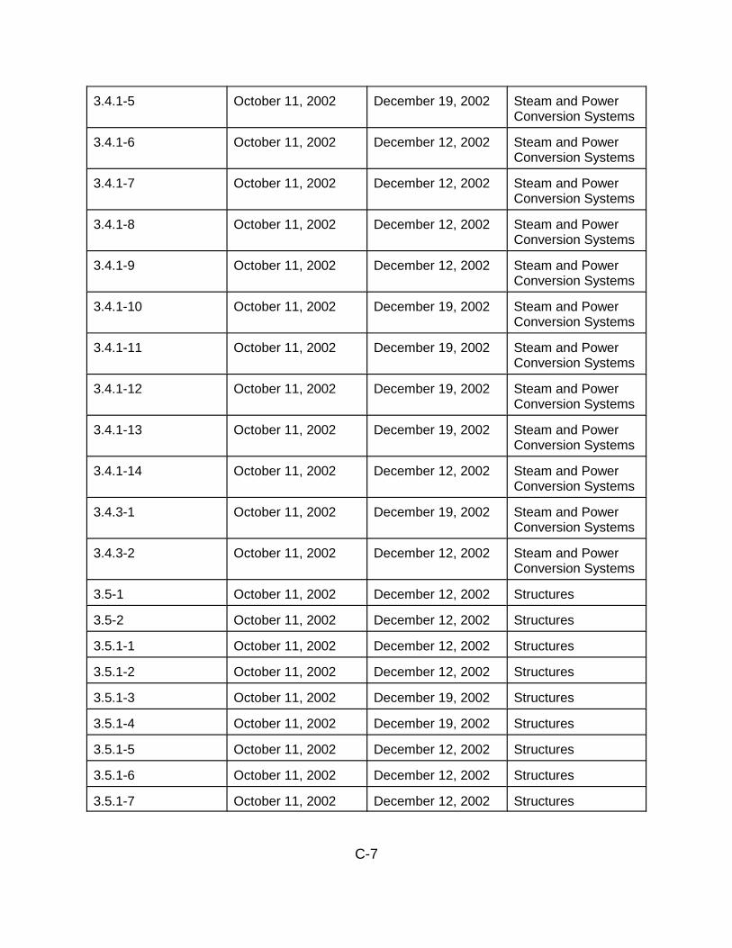
C-7
3.4.1-5 October 11, 2002 December 19, 2002 Steam and PowerConversion Systems
3.4.1-6 October 11, 2002 December 12, 2002 Steam and PowerConversion Systems
3.4.1-7 October 11, 2002 December 12, 2002 Steam and PowerConversion Systems
3.4.1-8 October 11, 2002 December 12, 2002 Steam and PowerConversion Systems
3.4.1-9 October 11, 2002 December 12, 2002 Steam and PowerConversion Systems
3.4.1-10 October 11, 2002 December 19, 2002 Steam and PowerConversion Systems
3.4.1-11 October 11, 2002 December 19, 2002 Steam and PowerConversion Systems
3.4.1-12 October 11, 2002 December 19, 2002 Steam and PowerConversion Systems
3.4.1-13 October 11, 2002 December 19, 2002 Steam and PowerConversion Systems
3.4.1-14 October 11, 2002 December 12, 2002 Steam and PowerConversion Systems
3.4.3-1 October 11, 2002 December 19, 2002 Steam and PowerConversion Systems
3.4.3-2 October 11, 2002 December 12, 2002 Steam and PowerConversion Systems
3.5-1 October 11, 2002 December 12, 2002 Structures
3.5-2 October 11, 2002 December 12, 2002 Structures
3.5.1-1 October 11, 2002 December 12, 2002 Structures
3.5.1-2 October 11, 2002 December 12, 2002 Structures
3.5.1-3 October 11, 2002 December 19, 2002 Structures
3.5.1-4 October 11, 2002 December 19, 2002 Structures
3.5.1-5 October 11, 2002 December 12, 2002 Structures
3.5.1-6 October 11, 2002 December 12, 2002 Structures
3.5.1-7 October 11, 2002 December 12, 2002 Structures

C-8
3.5.1-8 October 11, 2002 December 19, 2002 Structures
3.5.1-9 October 11, 2002 December 19, 2002 Structures
3.5.1-10 October 11, 2002 December 19, 2002 Structures
3.5.1-11 October 11, 2002 December 19, 2002 Structures
3.5.1-12 October 11, 2002 December 12, 2002 Structures
3.5.1-13 October 11, 2002 December 19, 2002 Structures
3.5.1-14 October 11, 2002 December 19, 2002 Structures
3.5.1-15 October 11, 2002 December 19, 2002 Structures
3.5.1-16 October 11, 2002 December 19, 2002 Structures
3.5.1-17 October 11, 2002 December 12, 2002 Structures
3.5.1-18 October 11, 2002 December 19, 2002 Structures
3.5.1-19 October 11, 2002 December 19, 2002 Structures
3.5.3-1 October 11, 2002 December 12, 2002 Structures
3.6-1 October 11, 2002 December 19, 2002 Electrical and I&C
4.1-1 October 11, 2002 December 12, 2002 Identification ofTime-Limited AgingAnalyses
4.2-1 October 11, 2002 December 19, 2002 Reactor VesselNeutronEmbrittlement
4.2-2 October 11, 2002 December 19, 2002 Reactor VesselNeutronEmbrittlement
4.3.1-1 October 11, 2002 December 19, 2002 Metal Fatigue
4.3.2-1 October 11, 2002 December 19, 2002 Metal Fatigue
4.3.2-2 October 11, 2002 December 12, 2002 Metal Fatigue
4.3.2-3 October 11, 2002 December 19, 2002 Metal Fatigue
4.3.4-1 October 11, 2002 December 12, 2002 Metal Fatigue
4.5-1 October 11, 2002 December 19, 2002 ConcreteContainment TendonPrestress

C-9
4.5-2 October 11, 2002 December 19, 2002 ConcreteContainment TendonPrestress
4.6-1 October 11, 2002 December 12, 2002 Containment LinerPlate andPenetration SleeveFatigue
4.7.1-1 October 11, 2002 December 19, 2002 Reactor CoolantPump FlywheelFatigue
4.7.2-1 October 11, 2002 December 19, 2002 Leak-Before-Break
B.1-1 October 11, 2002 December 19, 2002 Aging ManagementPrograms
B.1-2 October 11, 2002 December 19, 2002 Aging ManagementPrograms
B.1.1-1 October 11, 2002 December 19, 2002 Bolting IntegrityProgram
B.1.2-1 October 11, 2002 December 19, 2002 Chemistry Program
B.1.3-1 October 11, 2002 December 12, 2002December 19, 2002
ContainmentInservice InspectionProgram
B.1.3-2 October 11, 2002 December 19, 2002 ContainmentInservice InspectionProgram
B.1.4-1 October 11, 2002 December 12, 2002 Containment LeakRate Program
B.1.5-1 October 11, 2002 December 19, 2002 Flow-AcceleratedCorrosion Program
B.1.7-1 October 11, 2002 December 19, 2002 Reactor VesselIntegrity Program
B.2.1-1 October 11, 2002 December 19, 2002 Boric Acid CorrosionPrevention Program
B.2.1-2 October 11, 2002 December 12, 2002 Boric Acid CorrosionPrevention Program
B.2.3-1 October 11, 2002 December 19, 2002 Diesel FuelMonitoring andStorage Program

C-10
B.2.3-2 October 11, 2002 December 19, 2002 Diesel FuelMonitoring andStorage Program
B.2.3-3 October 11, 2002 December 12, 2002 Diesel FuelMonitoring andStorage Program
B.2.4-1 October 11, 2002 December 12, 2002 Fatigue MonitoringProgram
B.2.4-2 October 11, 2002 December 19, 2002 Fatigue MonitoringProgram
B.2.5-1 October 11, 2002 December 19, 2002 Fire ProtectionProgram
B.2.5-2 October 11, 2002 December 12, 2002 Fire ProtectionProgram
B.2.5-3 October 11, 2002 December 19, 2002 Fire ProtectionProgram
B.2.5-4 October 11, 2002 December 19, 2002 Fire ProtectionProgram
B.2.5-5 October 11, 2002 December 19, 2002 Fire ProtectionProgram
B.2.7-1 October 11, 2002 December 19, 2002 Periodic Surveillanceand PreventiveMaintenanceProgram
B.2.7-2 October 11, 2002 December 19, 2002 Periodic Surveillanceand PreventiveMaintenanceProgram
B.2.8-1 October 11, 2002 December 19, 2002 Reactor VesselInternals InspectionProgram
B.2.9-1 October 11, 2002 December 19, 2002 Steam GeneratorProgram
B.2.9-2 October 11, 2002 December 19, 2002 Steam GeneratorProgram
B.3.1-1 October 11, 2002 December 19, 2002 Alloy 600 Program

C-11
B.3.2-1 October 11, 2002 December 12, 2002 Buried SurfacesExternal CorrosionProgram
B.3.2-2 October 11, 2002 December 19, 2002 Buried SurfacesExternal CorrosionProgram
B.3.3-1 October 11, 2002 December 19, 2002 General Corrosion ofExternal SurfacesProgram
B.3.3-2 October 11, 2002 December 19, 2002 General Corrosion ofExternal SurfacesProgram
B.3.3-3 October 11, 2002 December 12, 2002 General Corrosion ofExternal SurfacesProgram
B.3.3-4 October 11, 2002 December 12, 2002 General Corrosion ofExternal SurfacesProgram
B.3.3-5 October 11, 2002 December 19, 2002 General Corrosion ofExternal SurfacesProgram
B.3.3-6 October 11, 2002 December 19, 2002 General Corrosion ofExternal SurfacesProgram
B.3.4-1 October 11, 2002 December 19, 2002 Non-EQ Cable AgingManagementProgram
B.3.6-1 October 11, 2002 December 19, 2002 Selective LeachingProgram
B.3.6-2 October 11, 2002 December 19, 2002 Selective LeachingProgram

D-1
APPENDIX D
PRINCIPAL CONTRIBUTORS
LICENSE RENEWAL AND ENVIRONMENTAL IMPACTS PROGRAM
NAME RESPONSIBILITY
Pao-Tsin Kuo Branch ChiefSam Lee Section ChiefWilliam Burton Project ManagerSonary Chey Clerical SupportThelma Davis Clerical SupportYvonne Edmonds Administrative SupportAlvin Henry Technical SupportMelissa Jenkins Administrative SupportTomeka Terry Technical SupportJacqwan Walker Technical SupportHai-Boh Wang Technical SupportAlicia Williamson Technical Support
PRINCIPAL CONTRIBUTORS
NAME RESPONSIBILITY
Hans Ashar Civil EngineeringStewart Bailey Mechanical EngineeringPeter Balmain Quality AssuranceOm Chopra Electrical EngineeringDavid Cullison Plant Systems EngineeringBarry Elliot Materials EngineeringJohn Fair Mechanical EngineeringTom Farnholtz Inspection SupportEd Forrest Plant Systems EngineeringVincent Gaddy Inspection SupportGreg Galletti Quality AssuranceAmritpal Gill Electrical EngineeringJoe Golla Plant Systems EngineeringJin Guo Plant Systems EngineeringGregory Hatchett Plant Systems EngineeringDiane Jackson Plant Systems EngineeringDavid Jeng Civil EngineeringSteve Jones Plant Systems EngineeringCheryl Khan Materials EngineeringMeena Khanna Materials and Chemical EngineeringYong Kim Mechanical EngineeringCarol Lauron Materials EngineeringArnold Lee Mechanical Engineering

D-2
Chang Li Plant Systems EngineeringRenee Li Mechanical EngineeringJohn Ma Civil EngineeringTom McLellan Materials EngineeringJames Medoff Materials EngineeringJames Melfi Inspection SupportTanya Mensah Fire Protection EngineeringMatthew Mitchell Materials EngineeringRay Mullikin Inspection SupportCliff Munson Structural EngineeringKris Parczewski Chemical EngineeringPat Patnaik Materials EngineeringJames Pulsipher Plant Systems EngineeringJai Rajan Mechanical EngineeringMuhammad Razzaque Reactor Systems EngineeringSimon Sheng Mechanical EngineeringDavid Shum Plant Systems EngineeringApril Smith Materials EngineeringFrank Talbot Quality AssuranceHarold Walker Plant Systems EngineeringWayne Walker Inspection Team LeaderAlan Wang Inspection SupportLeonard Willoughby Inspection Support