· safety instructions the equipment described herein has been developed, produced, tested and...
TRANSCRIPT

www.DanaherMotion.com
6215 Microstep Drive/Oscillator
Installation Manual MA6215
Rev. B
D A N A H E RM O T I O N
Solut ions by

Version History Revision Date Description of Revision 1 10/31/02 Initial Release B 5/17/04 Updated Corporate Identity
© Copyright 2002 - 2004 Danaher Motion All rights reserved. Printed in the United States of America.
DANAHER MOTION is a registered trademark of Danaher Corporation. Danaher Motion makes every attempt to ensure accuracy and reliability of the specifications in this publication. Specifications are subject to change without notice. Danaher Motion provides this information "AS IS" and disclaims all warranties, express or implied, including, but not limited to, implied warranties of merchantability and fitness for a particular purpose. It is the responsibility of the product user to determine the suitability of this product for a specific application.
Warning Alerts users to potential physical danger or harm. Failure to follow warning notices could result in personal injury or death.
Caution Directs attention to general precautions, which if not followed, could result in personal injury and/or equipment damage.
Note Highlights information critical to your understanding or use of the product.

SAFETY INSTRUCTIONS The equipment described herein has been developed, produced, tested and documented in accordance with the corresponding standards. During use conforming with requirements, the equipment is not dangerous for people or equipment. Use conforming with requirements means that the safety recommendations and warnings detailed in this manual are complied with and applicable regulations for safety (machine directives, etc.) and noise suppression (EMC Directives) are observed while operating the drive. At the end of its lifetime, dispose of or recycle the drive according to the applicable regulations.
Installation and wiring of the drive must be completed only by qualified personnel having a basic knowledge of electronics, installation of electronic and mechanical components, and all applicable wiring regulations.
Commissioning of the machine utilizing the drives must be done only by qualified personnel having a broad knowledge of electronics and motion control technology.
This unit is designed only for 24-40 VDC input (see Electrical under Specifications).
Before performing any work on the unit, allow at least five minutes for the capacitors to fully discharge.
Voltage is present on unprotected pins when the unit is operational.
Motors powered by this drive may develop extremely high torque. Disconnect power to this drive before doing any mechanical work.

SUITABILITY AND WARRANTY Reconfiguration of the circuit not shown in this manual voids the Warranty.
Failure to follow the installation guidelines voids the Warranty.
As the user or person applying this unit, you are responsible for determining the suitability of this product for the application. In no event is Danaher Motion responsible or liable for indirect or consequential damage resulting from the misuse of this product.
Read this manual completely to effectively and safely operate the 6215.
Comply with the applicable European standards and Directives

Danaher Motion Pacific Scientific 05/04 Table Of Contents
6215 Installation Manual MA6215 Rev. B i
TABLE OF CONTENTS 1 INTRODUCTION ....................................................................................1
1. 1 PRODUCT FEATURES........................................................................... 1 1. 2 EXPRESS START-UP PROCEDURE......................................................... 1
2 INSTALLATION GUIDELINES................................................................3 2. 1 MOUNTING DIMENSIONS....................................................................... 3 2. 2 TERMINAL LOCATIONS AND ASSIGNMENTS ............................................. 4
2.2.1. Terminal Locations Diagram......................................................... 4 2.2.2. Motor Connections ....................................................................... 4 2.2.3. Motor Wiring Configurations ......................................................... 5
2.2.3.1. P2H, P21, M21, P22, M22.................................................... 5 2.2.3.2. N3x / K3x / T2x ..................................................................... 6 2.2.3.3. 4 flying leads or 4 terminals or MS connector....................... 8
2.2.4. Phase Sequencing Tables............................................................ 9 2.2.5. Power Input Connections ............................................................. 9
2.2.5.1. Typical Power Supply for a Single Drive Application .......... 10
3 SPECIFICATIONS ................................................................................11 3. 1 MECHANICAL .................................................................................... 11 3. 2 ELECTRICAL...................................................................................... 11 3. 3 ENVIRONMENTAL............................................................................... 11 3. 4 CURRENT SETTINGS.......................................................................... 11 3. 5 AUTOMATIC CURRENT REDUCTION (SWITCH 6) .................................... 12 3. 6 RUN SPEED SOURCE (SWITCH 7) ....................................................... 12 3. 7 EXTERNAL SPEED INPUT SCALING (SWITCH 8) ..................................... 12 3. 8 POTENTIOMETERS............................................................................. 12
3.8.1. Switch and Potentiometer Locations .......................................... 13 3. 9 SIGNAL SPECIFICATIONS .................................................................... 14
3.9.1. Terminal Assignments ................................................................ 14 3.9.2. Signal Descriptions..................................................................... 14 3.9.3. Level Requirements.................................................................... 15
3.9.3.1. Suggested Methods for Control Interface ........................... 15 3.9.4. Timing Considerations................................................................ 16
3.9.4.1. Timing Considerations Diagram ......................................... 17 3. 10 INDICATOR LIGHTS............................................................................. 18
4 TORQUE VS. SPEED...........................................................................19 4. 1 MOTOR COMPATIBILITY...................................................................... 19
4.1.1. Motors For Use With The 6215 Drive/Oscillator ......................... 20 4.1.1.1. Specifications ..................................................................... 20 Std. Ltr. Winding, Connection, Drive Amps, Rated Motor Current, Phase Resistance by Motor Type...................................................................... 20 Phase Inductance, Holding Torque, Rotor Inertia, and Detent Torque by Motor Type ............................................................................................. 21
4. 2 MOTOR PERFORMANCE ..................................................................... 23 4. 3 TYPICAL TORQUE VS. SPEED CURVES ................................................ 24
4.3.1. P2H, 24 V ................................................................................... 24 4.3.2. P2H, 36 V ................................................................................... 25 4.3.3. P21, 24 V.................................................................................... 25 4.3.4. P21/M21, 36 V............................................................................ 26 4.3.5. P22/M22, 24 V............................................................................ 26 4.3.6. P22/M22, 36 V............................................................................ 27

Table Of Contents 05/04 Danaher Motion Pacific Scientific
ii MA6215 Rev. B 6215 Installation Manual
4.3.7. T2H, 24 V ................................................................................... 27 4.3.8. T20, 36 V .................................................................................... 28 4.3.9. T21, 24 V .................................................................................... 28 4.3.10. T21, 36 V .................................................................................... 29 4.3.11. T22, 24 V .................................................................................... 29 4.3.12. T22, 36 V .................................................................................... 30 4.3.13. T23, 24 V .................................................................................... 30 4.3.14. T23, 36 V .................................................................................... 31 4.3.15. N31/K31, 36 V ............................................................................ 31 4.3.16. N32/K32, 36 V ............................................................................ 32
5 TROUBLESHOOTING ......................................................................... 33 5. 1 IN GENERAL...................................................................................... 33 5. 2 SPECIFICALLY ................................................................................... 33 5. 3 ELECTRICAL INTERFERENCE PROBLEMS............................................... 34 5. 4 CUSTOMER SUPPORT ........................................................................ 34

Danaher Motion Pacific Scientific 05/04 Introduction
6215 Installation Manual MA6215 Rev. B 1
1 INTRODUCTION
1. 1 Product Features The 6215 drive/oscillator combines a bipolar, two-phase PWM drive that uses hybrid power devices and a control/oscillator in one compact package. Micro-stepping at 1/32 step resolution (6400 pulses/revolution) is used to ensure smooth low-speed operation. The maximum running speed is 3,000 rpm. Features include:
– Switch selectable current levels of 1.0 A through 3.5 A – Microprocessor-based digital oscillator for accurate speed
control – Built-in potentiometers for acceleration, deceleration, low
speed, and run speed – Full short-circuit protection (phase-to-phase and phase-to-
ground) – Undervoltage and transient overvoltage protection – Efficient thermal design – Windings Off capability – User-selectable automatic current reduction at standstill – Compact size – Sturdy all-aluminum mounting base – Run speed control from built-in potentiometer or external
voltage input
1. 2 Express Start-Up Procedure The following instructions define the minimum steps necessary to make your drive/oscillator operational:
Always disconnect the power to the unit before connecting or disconnecting the motor leads. FAILURE TO DO SO WILL RESULT IN A SHOCK HAZARD AND MAY DAMAGE THE DRIVE.
Always operate the unit with the motor and drive enclosure GROUNDED. Be sure to twist together the wires for each motor phase as well as those for the DC input. Six twists per foot (0.3 m) is a good guideline.
1. Check to see that the motor used is compatible with the drive/oscillator.
2. Set the correct current level for the motor being used per the instructions in Current Settings. Heat sinking may be required to maintain case temperature below +70° C (+158° F).
3. Select the desired motor current at standstill (50% or 100%) and set switch 6 as described in Automatic Current Reduction (Switch 6).

Installation Guidelines 05/04 Danaher Motion Pacific Scientific
2 MA6215 Rev. B 6215 Installation Manual
4. Select the appropriate run speed source (on board trim pot or external input) and set switch 7 as described in Run Speed Source (Switch 7). If an external run speed voltage source is to be used, select the appropriate voltage range (0 to 5 V or 0 to 10 V) and set switch 8 as described in External Speed Input Scaling (Switch 8).
5. Wire the motor according to Motor Connections.
6. Connect the power source to the DC input terminal strip. Be sure to follow the instructions for connecting the filter capacitor as described in Power Input Connections.
7. Set the desired acceleration rate, deceleration rate, Low speed, and motor running speed using the appropriate potentiometers as described in Current Settings
If the motor operates erratically, refer to Torque vs. Speed.
Clockwise and counter-clockwise directions are properly oriented when viewing the motor from the end opposite the mounting flange.

Danaher Motion Pacific Scientific 05/04 Installation Guidelines
6215 Installation Manual MA6215 Rev. B 3
2 INSTALLATION GUIDELINES The 6215 drive/oscillator is mounted by fastening its mounting brackets to a flat surface. Dimensions are shown in Mounting Dimensions. If the drive/oscillator assembly is mounted against a bulkhead, be sure to apply a thin coating of thermal compound between the drive and the mounting surface before fastening the unit in place.
Do not use too much thermal compound. It is better to use too little than too much.
2. 1 Mounting Dimensions
Case temperature must not exceed +70° C (+158° F).
When selecting a mounting location, it is important to leave at least two inches (51 mm) of space around the top, bottom, and sides of the unit to allow proper airflow for cooling.

Installation Guidelines 05/04 Danaher Motion Pacific Scientific
4 MA6215 Rev. B 6215 Installation Manual
It is also important to keep the drive away from obvious noise sources. If possible, locate the drive in its own metal enclosure to shield it and its wiring from electrical noise sources. If this cannot be done, keep the drive at least three feet (0.9 m) from any noise sources.
2. 2 Terminal Locations and Assignments
2.2.1. TERMINAL LOCATIONS DIAGRAM
2.2.2. MOTOR CONNECTIONS All motor connections are made via the 6-terminal strip. Terminal assignments are given below. Motor connections are shown in Motor Wiring Configurations
J2 Pin Assignment1 M1 (Phase A+) 2 M3 (Phase A-) 3 M4 (Phase B+) 4 M5 (Phase B-)
Motor Phase A is M1 and M3. Motor Phase B is M4 and M5. The motor frame must be grounded.

Danaher Motion Pacific Scientific 05/04 Installation Guidelines
6215 Installation Manual MA6215 Rev. B 5
2.2.3. MOTOR WIRING CONFIGURATIONS 2.2.3.1. P2H, P21, M21, P22, M22
Phase sequencing direction of rotation as viewed from mounting end of motor.
4-Lead m otor (B ipolar)PAR ALLEL
6
2
5
1
8 4 7 3
B
A
B
A
W HT/O RG
W HT/BLK
BLK
O RG
W HT/RED
W HT/YEL
RED YEL
6
2
5
1
8 4 7 3
A
B
A
B
SER IES
W HT/BLK
BLK
ORG
W HT/RED
W HT/YEL
RED YEL
8-Lead m otor (reference)
W HT/O RG
WH
T/R
ED
WH
T/YE
L
W HT/BLK
BLK
ORG
RE
D
YEL
6
2
5
1
8 4 7 3
PH
ASE
A
PH ASE B
DRIVE CONNECTION
STEP A B C D
1 GND O GND O
2 O GND GND O
3 O GND O GND
4 GND O O GND
CCW
1 GND O GND O
CW

Installation Guidelines 05/04 Danaher Motion Pacific Scientific
6 MA6215 Rev. B 6215 Installation Manual
DRIVE CONNECTION
STEP A B
1 + ⎯ ⎯ +
2 ⎯ + ⎯ +
3 ⎯ + + ⎯
4 + ⎯ + ⎯
CCW
1 + ⎯ ⎯ +
CW
O = off or open GND = ground + = positive current flow -⎯ = negative currrent flow
2.2.3.2. N3x / K3x / T2x Power Connections: 8 flying leads or 8 terminals. The 8-lead motor is the most versatile configuration. It may be connected by you in a choice of 8-lead or 4-lead (series or parallel).
T2x is offered only with flying leads.
BLK
ORG
WHT/ORGBLK/ORG
RED YELWHT/YELWHT/RED
8-Lead Configuration
Terminal BoardN3x/K3x
1 2
3 4
5
6
7
8
Danaher Motion Pacific Scientific 05/04 Installation Guidelines
6215 Installation Manual MA6215 Rev. B 7
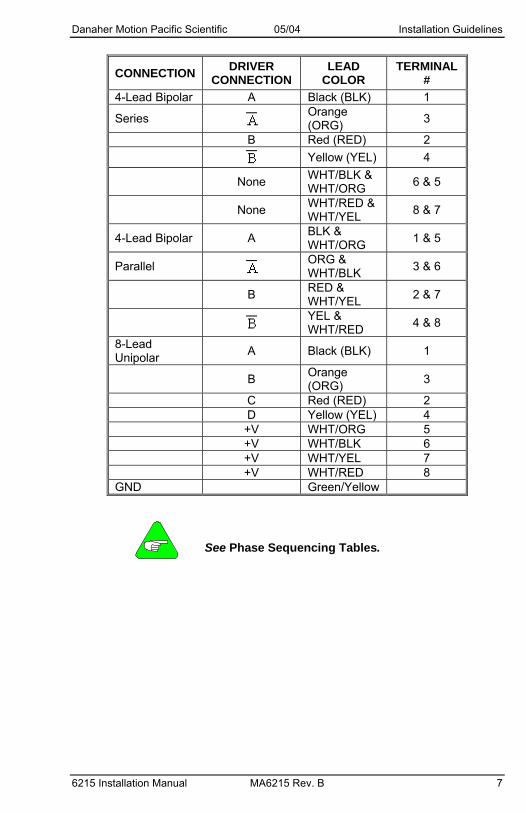
CONNECTION DRIVER CONNECTION
LEAD COLOR
TERMINAL #
4-Lead Bipolar A Black (BLK) 1
Series Orange (ORG) 3
B Red (RED) 2 Yellow (YEL) 4
None WHT/BLK & WHT/ORG 6 & 5
None WHT/RED & WHT/YEL 8 & 7
4-Lead Bipolar A BLK & WHT/ORG 1 & 5
Parallel ORG & WHT/BLK 3 & 6
B RED & WHT/YEL 2 & 7
YEL & WHT/RED 4 & 8
8-Lead Unipolar A Black (BLK) 1
B Orange (ORG) 3
C Red (RED) 2 D Yellow (YEL) 4 +V WHT/ORG 5 +V WHT/BLK 6 +V WHT/YEL 7 +V WHT/RED 8 GND Green/Yellow
See Phase Sequencing Tables.

Installation Guidelines 05/04 Danaher Motion Pacific Scientific
8 MA6215 Rev. B 6215 Installation Manual
2.2.3.3. 4 flying leads or 4 terminals or MS connector.
The 4-lead motor is used with bipolar drives.
AB
CD
E
MS ConnectorN3x/K3x
Terminal BoardN3x/K3x
1 2
3 4
5
6
7
8
BLK
ORG
4-Lead Configuration
RED YEL
CONNECTION DRIVER
CONNECTION LEAD COLOR TERMINAL # MS PIN OUT4-Lead Bipolar A Black (BLK) 1 A
Orange (ORG) 3 B B Red (RED) 2 C Series
Yellow (YEL) 4 D GND Green/Yellow E
Terminals 7 & 8 are not used. See Phase Sequencing Tables.

Danaher Motion Pacific Scientific 05/04 Installation Guidelines
6215 Installation Manual MA6215 Rev. B 9
2.2.4. PHASE SEQUENCING TABLES BIPOLAR HALF STEP
DRIVE CONNECTION
STEP A B
1 + ⎯ 0 0
2 + ⎯ + ⎯
3 0 0 + ⎯
4 ⎯ + + ⎯
5 ⎯ + 0 0
6 ⎯ + ⎯ +
7 0 0 ⎯ +
CCW
8 + ⎯ ⎯ +
CW
BIPOLAR FULL STEP
DRIVE CONNECTION
STEP A B
1 + ⎯ ⎯ +
2 ⎯ + ⎯ +
3 ⎯ + + ⎯
4 + ⎯ + ⎯
CCW
1 + ⎯ ⎯ +
CW
O = off or open GND = ground + = positive current flow -⎯ = negative currrent flow
2.2.5. POWER INPUT CONNECTIONS The DC input power is connected to terminals 5 and 6 of the terminal strip. Terminal 5 [VM(+)] is the power supply plus (+) connection and pin 6 [VOM(-)] is the power supply minus (-) connection.
Installation Guidelines 05/04 Danaher Motion Pacific Scientific
10 MA6215 Rev. B 6215 Installation Manual
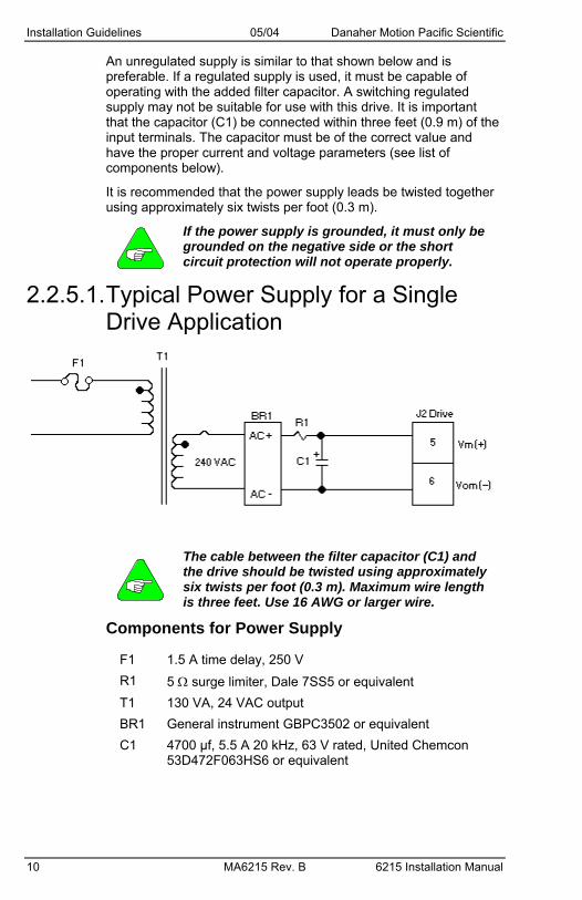
An unregulated supply is similar to that shown below and is preferable. If a regulated supply is used, it must be capable of operating with the added filter capacitor. A switching regulated supply may not be suitable for use with this drive. It is important that the capacitor (C1) be connected within three feet (0.9 m) of the input terminals. The capacitor must be of the correct value and have the proper current and voltage parameters (see list of components below).
It is recommended that the power supply leads be twisted together using approximately six twists per foot (0.3 m).
If the power supply is grounded, it must only be grounded on the negative side or the short circuit protection will not operate properly.
2.2.5.1. Typical Power Supply for a Single Drive Application
The cable between the filter capacitor (C1) and the drive should be twisted using approximately six twists per foot (0.3 m). Maximum wire length is three feet. Use 16 AWG or larger wire.
Components for Power Supply
F1 1.5 A time delay, 250 V R1 5 Ω surge limiter, Dale 7SS5 or equivalent T1 130 VA, 24 VAC output BR1 General instrument GBPC3502 or equivalent C1 4700 µf, 5.5 A 20 kHz, 63 V rated, United Chemcon
53D472F063HS6 or equivalent

Danaher Motion Pacific Scientific 05/04 Specifications
6215 Installation Manual MA6215 Rev. B 11
3 SPECIFICATIONS
3. 1 Mechanical Size (inches) 1.56 H X 4.13 W x 3.25 D (mm) 40 H x 105 W x 83 D Weight 10.3 ounces (292 grams)
3. 2 Electrical DC Input Range 24 VDC min., 40 VDC max. DC Current see Motor Table Drive Power Dissipation (worse case)
35 watts
3. 3 Environmental Operating Temperature +32° F to 122° F (0° C to 50° C) free
air ambient, Natural Convection. Maximum heat sink temperature at 158° F (70° C) must be maintained. Forced-air cooling may be required.
Storage Temperature -40° F to +167° F (-40° C to + 75° C) Humidity 95% max. non-condensing Altitude 10,000 feet (3048 m) max.
3. 4 Current Settings The proper current setting for each motor is shown on the individual torque vs. speed curves. Use this current level to obtain the torque shown. Switches 1 through 5 are used to select the current level. Select the desired operating current by setting the appropriate switch to position 1 (ON). The OFF position is labeled "0". Only one switch should be ON. If two or more switches are ON, the one which selects the highest current level will be the active switch. The switch settings are:
Position Current (Amps) None (All OFF) 1.0
1 1.5 2 2.0 3 2.5 4 3.0 5 3.5

Specifications 05/04 Danaher Motion Pacific Scientific
12 MA6215 Rev. B 6215 Installation Manual
3. 5 Automatic Current Reduction (Switch 6) When switch 6 is in the OFF position, the current at standstill goes to 50% of the selected level. This occurs between 1 and 2 seconds after the last pulse is received. When switch 6 is in the ON position, the current at standstill remains at full value.
3. 6 Run Speed Source (Switch 7) When switch 7 is in the OFF position, the on-board speed potentiometer is used as the run speed source. When switch 7 is in the ON position, an external voltage applied to input VIN is used as the run speed source. External Speed Input Scaling (Switch 8) provides information on the scaling of this input.
3. 7 External Speed Input Scaling (Switch 8) The external speed input (VIN) scaling is selected using switch 8. Placing switch 8 in the OFF position selects 0 V - 5 V as the range of the external speed input. The ON position sets the input range to 0 V - 10 V.
3. 8 Potentiometers On-board potentiometers are provided for setting the following motion parameters: acceleration, deceleration, low speed, and run speed. Run speed can also be set via an external potentiometer (see Run Speed Source (Switch 7)) or an external voltage input 0 – 5 V or 0 – 10 V (see External Speed Input Scaling (Switch 8)).
The drive/oscillator is implemented using digital techniques. Micro-stepping at 1/32 step resolution (6400 pulses/revolution) is used to ensure smooth operation at low speeds. The settings for acceleration, deceleration, low speed and speed are analog by nature and are converted to digital form using an 8-bit A/D. This results in granularity in the resolution settings. The ranges of each parameter are specifically in full steps/sec. and full steps/sec2.

Danaher Motion Pacific Scientific 05/04 Specifications
6215 Installation Manual MA6215 Rev. B 13
3.8.1. SWITCH AND POTENTIOMETER LOCATIONS
Parameter Description Range Resolution (8 bits)
Acceleration Rate at which motor speed increases
4000 – 120,000
500 full steps/sec2
Deceleration Rate at which motor speed decreases
4000 – 120,000
500 full steps/sec2
Low speed Motor starting speed 0 – 1200 40 full steps/sec Speed Motor running speed 0 – 10,000 40 full steps/sec

Specifications 05/04 Danaher Motion Pacific Scientific
14 MA6215 Rev. B 6215 Installation Manual
3. 9 Signal Specifications 3.9.1. TERMINAL ASSIGNMENTS
All connections are made via the 7-pin terminal strip.
J1 Pin Assignment 1 LOW SPEED 2 DIR 3 RUN 4 AWO 5 GND 6 EXT SPEED 7 +5V
3.9.2. SIGNAL DESCRIPTIONS LOW SPEED
Low Speed Input (J1-1)
When this input is activated (tied to GND), the RUN SPEED is set by the low speed Potentiometer.
DIR Direction Input (J1-2)
When this signal is high, motor rotation is clockwise. Rotation is counter-clockwise when this signal is low.
RUN Run Input (J1-3)
When this signal is low, the motor will run in the direction set by the DIR input at the desired set speed.
AWO All Windings Off Input (J1-4)
When this signal is low, AC and DC current to the motor is zero.
There is no holding torque when the AWO signal is low.
GND Signal ground (J1-5)
This ground point can be used for activating the discrete input signals on pins J1-1 through J1-4. It can also be used as a reference point for an external voltage input or in conjunction with the +5 V output (J1-7) to power an external speed potentiometer.

Danaher Motion Pacific Scientific 05/04 Specifications
6215 Installation Manual MA6215 Rev. B 15
EXT SPEED
External Run Speed Input (J1-6) This is an optional input that can be used in place of the on-board run speed potentiometer. Input range can either be 0 – 5 V or 0 – 10 V as defined by switch 8 described in External Speed Input Scaling (Switch 8).
+5V +5 V Output (J1-7) This output is provided for powering an external speed potentiometer. Pin J1-5 is used as the ground reference.
3.9.3. LEVEL REQUIREMENTS External Speed Input (EXT SPEED) Voltage 0 - 10 VDC Input Impedance 100 k Ω I/O Signals Voltage Low ≤2.0 VDC ≥0.0 VDC High ≥3.0 VDC Open Circuit Input Voltage 5 VDC Typical Current Logic 0 sink current ≤1 mA
3.9.3.1. Suggested Methods for Control Interface

Specifications 05/04 Danaher Motion Pacific Scientific
16 MA6215 Rev. B 6215 Installation Manual
3.9.4. TIMING CONSIDERATIONS
Refer to Timing Considerations Diagram
When the RUN input is activated, the motor goes from 0 speed to Low speed either immediately or after a 50 ms delay. If the Low speed input is active, the motor speed stays at Low speed. Otherwise, the speed is increased to the Run speed at the acceleration rate set via the ACCEL potentiometer. When the RUN input is removed, the motor speed is decreased to Low speed at the deceleration rate via the DECEL potentiometer. Upon reaching Low speed, the motor stops.
If selected, Auto Reduce Current takes effect 50 ms after the motor stops. The DIR input, which determines the motor rotation direction, is sampled when the RUN input goes active (Low tied to GND).
All of the switch settings, potentiometer settings, and input signals can be changed on-the-fly with the new settings (except DIR), effective immediately. The Timing Considerations Diagram depicts the timing relationships between the RUN input, motor speed, and motor current.

Danaher Motion Pacific Scientific 05/04 Specifications
6215 Installation Manual MA6215 Rev. B 17
3.9.4.1. Timing Considerations Diagram

Specifications 05/04 Danaher Motion Pacific Scientific
18 MA6215 Rev. B 6215 Installation Manual
3. 10 Indicator Lights "Fault LED, Red
Lights to indicate over current condition. This condition is caused by motor winding errors or a ground fault.
Recovery from over current condition requires removing and then reapplying the power.
Danaher Motion Pacific Scientific 05/04 Torque vs. Speed
6215 Installation Manual MA6215 Rev. B 19
4 TORQUE VS. SPEED
4. 1 Motor Compatibility Motor Types Danaher Motion
T, PSeries Frame Sizes TBD
N, K Series Frame Sizes TBD
Number of Connections 4, 6, 8
Minimum Inductance 0.5 mH
Maximum Resistance 0.25 x VDC Supply/I Setting
Example:
VDC = 30 I Setting = 3.5 R max. = 0.25 x 30/3.5 = 2.1 Ω
Do not use larger frame size motor than those listed or the drive/oscillator may be damaged. If a larger frame size motor must be used, consult Danaher Motion for recommendation.
Maximum resistance is total of motor plus cable.

Torque vs. Speed 05/04 Danaher Motion Pacific Scientific
20 MA6215 Rev. B 6215 Installation Manual
4.1.1. MOTORS FOR USE WITH THE 6215 DRIVE/OSCILLATOR
4.1.1.1. Specifications Std. Ltr. Winding, Connection, Drive Amps, Rated Motor Current, Phase Resistance by Motor Type
Motor Type
STD. LTR. WINDING
ConnectionS= Series P=Parallel
Drive Amps I (rms)
Rated Motor
Current Ic (Amps)
Phase Resistance
Ohms @25C
P2H C Series 1.0 1.2 3.35 P2H C Parallel 2.5 2.5 0.84 P2H F Parallel 1.0 1.6 1.92 P2H H Parallel 2.5 5.2 0.22
P21 A Series 2.5 2.8 0.91 P21 B Parallel 2.5 4.6 0.32 P21 C Parallel 3.5 3.5 0.53 P21 D Parallel 1.0 1.5 2.61 M21 C Parallel 3.5 3.5 0.53
P22 A Series 2.5 3.3 0.85 P22 B Parallel 3.5 4.6 0.38 P22 C Series 1.0 1.6 3.1 P22 D Parallel 2.5 2.5 1.22 P22 G Parrallel 1.0 1.0 7.35 M22 D Parallel 2.5 2.5 1.22 M22 G Parallel 1.0 1.0 7.35
T2H D Parallel 1 1.220 3.540 T2H G Parallel 2.5 3.000 0.580 T2H H Parallel 3.5 4.700 0.250 T21 E Parallel 1 1.540 2.930 T21 G Parallel 2.5 3.000 0.800 T21 H Parallel 3.5 4.800 0.320 T22 E Parallel 1 1.740 2.880 T22 G Parallel 2.5 2.700 1.210 T22 H Parallel 2.5 3.600 0.680 T22 J Parallel 3.5 4.400 0.460

Danaher Motion Pacific Scientific 05/04 Torque vs. Speed
6215 Installation Manual MA6215 Rev. B 21
Motor Type
STD. LTR. WINDING
ConnectionS= Series P=Parallel
Drive Amps I (rms)
Rated Motor
Current Ic (Amps)
Phase Resistance
Ohms @25C
T23 E Parallel 1 1.670 3.820 T23 H Parallel 3 3.300 0.970 T23 K Parallel 3.5 6.700 0.260
N31 K Series 2.5 3.3 1.16 N31 J Series 2.5 2.7 1.69 N31 J Parallel 3.5 5.5 0.42 K31 L Series 3.5 4.3 0.72 N32 L Series 2.5 4.1 1.03 N32 L Series 3.5 4.1 1.03 N32 M Series 3.5 5.0 0.7 K32 L Series 3.5 4.1 1.03
Phase Inductance, Holding Torque, Rotor Inertia, and Detent Torque by Motor Type
Motor Type Phase
Inductance Lp (mH)
Holding Totque Th
(OZ*IN) Rotor Inertia
Jm (OZ*IN*S^2) Detent
Torque Td (OZ*IN)
P2H 9.1 61 0.00096 2.5 P2H 2.3 61 0.00096 2.5 P2H 5.1 60 0.00096 2.5 P2H 0.5 59 0.00096 2.5
P21 3.4 114 0.00168 4 P21 1.1 111 0.00168 4 P21 2.3 116 0.00168 4 P21 10.3 109 0.00168 4 M21 2 144 0.00168 9.4
P22 3.3 197 0.00357 7 P22 2.1 214 0.00357 7 P22 15.4 203 0.00357 7 P22 6.2 203 0.00357 7 P22 37.4 200 0.00357 7 M22 5 238 0.00357 17 M22 30 235 0.00357 17

Torque vs. Speed 05/04 Danaher Motion Pacific Scientific
22 MA6215 Rev. B 6215 Installation Manual
Motor Type Phase
Inductance Lp (mH)
Holding Totque Th
(OZ*IN) Rotor Inertia
Jm (OZ*IN*S^2) Detent
Torque Td (OZ*IN)
T2H 13.600 78.852 0.002 2.000 T2H 2.200 78.901 0.002 2.000 T2H 1.000 80.123 0.002 2.000 T21 15.500 189.532 0.003 3.000 T21 4.500 194.501 0.003 3.000 T21 1.700 192.945 0.003 3.000 T22 16.400 304.536 0.006 6.000 T22 7.100 309.160 0.006 6.000 T22 3.500 297.244 0.006 6.000 T22 2.500 304.015 0.006 6.000 T23 23.100 413.562 0.008 7.000 T23 5.800 413.562 0.008 7.000 T23 1.400 414.092 0.008 7.000
N31 10.3 661 0.0202 18 N31 14 643 0.0202 18 N31 3.5 643 0.0202 18 K31 4.7 829 0.0202 25 N32 4.7 1199 .03798 36 N32 10.3 1199 0.03798 36 N32 7 1213 0.03798 36 K32 8.1 1512 0.03798 50
Power supply currents shown are measured at the output of the rectifier bridge. Danaher Motion motor reference. Motors with windings other than those listed can be used as long as the current ratings listed on the motors are not exceeded. All Danaher Motion motors listed have 8 leads.
Danaher Motion Pacific Scientific 05/04 Torque vs. Speed
6215 Installation Manual MA6215 Rev. B 23
4. 2 Motor Performance All stepper motors exhibit instability at their natural frequency and harmonics of that frequency. Typically, this instability occurs at speeds between 50 and 1000 full steps per second and, depending on the dynamic motor load parameters, can cause excessive velocity modulation or improper positioning. This type of instability is represented by the open area at the low end of each Torque vs. Speed curve.
There are also other instabilities that may cause a loss of torque at stepping rates outside the range of natural resonance frequencies. One such instability is broadly defined as mid-range instability. Usually, the damping of the system and acceleration/deceleration through the resonance areas aids in reducing the instability to a level that provides smooth shaft velocity and accurate positioning. If instability does cause unacceptable performance under actual operating conditions, the following techniques can be used to reduce velocity modulation. Avoid constant speed operation at the motor's unstable frequencies. Select a base speed above the motor's resonant frequencies and adjust acceleration and deceleration to move the motor through unstable regions quickly. The motor winding current can be reduced as described in Current Settings. Lowering the current reduces torque proportionally. The reduced energy delivered to the motor can decrease velocity modulation.

Torque vs. Speed 05/04 Danaher Motion Pacific Scientific
24 MA6215 Rev. B 6215 Installation Manual
4. 3 Typical Torque Vs. Speed Curves
The test conditions used when obtaining the torque vs. speed data are listed in the lower left-hand corner of each curve.
4.3.1. P2H, 24 V

Danaher Motion Pacific Scientific 05/04 Torque vs. Speed
6215 Installation Manual MA6215 Rev. B 25
4.3.2. P2H, 36 V
4.3.3. P21, 24 V

Torque vs. Speed 05/04 Danaher Motion Pacific Scientific
26 MA6215 Rev. B 6215 Installation Manual
4.3.4. P21/M21, 36 V
4.3.5. P22/M22, 24 V

Danaher Motion Pacific Scientific 05/04 Torque vs. Speed
6215 Installation Manual MA6215 Rev. B 27
4.3.6. P22/M22, 36 V
4.3.7. T2H, 24 V

Torque vs. Speed 05/04 Danaher Motion Pacific Scientific
28 MA6215 Rev. B 6215 Installation Manual
4.3.8. T20, 36 V
4.3.9. T21, 24 V

Danaher Motion Pacific Scientific 05/04 Torque vs. Speed
6215 Installation Manual MA6215 Rev. B 29
4.3.10. T21, 36 V
4.3.11. T22, 24 V

Torque vs. Speed 05/04 Danaher Motion Pacific Scientific
30 MA6215 Rev. B 6215 Installation Manual
4.3.12. T22, 36 V
4.3.13. T23, 24 V

Danaher Motion Pacific Scientific 05/04 Torque vs. Speed
6215 Installation Manual MA6215 Rev. B 31
4.3.14. T23, 36 V
4.3.15. N31/K31, 36 V

Torque vs. Speed 05/04 Danaher Motion Pacific Scientific
32 MA6215 Rev. B 6215 Installation Manual
4.3.16. N32/K32, 36 V

Danaher Motion Pacific Scientific 05/04 Troubleshooting
6215 Installation Manual MA6215 Rev. B 33
5 TROUBLESHOOTING
Motors connected to this drive can develop high torque and large amounts of mechanical energy. Keep clear of the motor shaft and all parts mechanically linked to the motor shaft. Turn off all power to the drive before performing work on parts mechanically-coupled to the motor.
5. 1 In General Check all installation wiring carefully for wiring errors or poor connections. Check to see that the proper voltage levels are being supplied to the unit. Be sure that the motor is a correct model for use with this unit.
5. 2 Specifically If MOTOR DIRECTION is reversed, check for:
– Reversed connection to the Motor Connector. Reversing the phase A or the phase B connections will reverse the direction of the motor rotation.
If the MOTOR MOTION is Erratic, check for: – Supply voltage out of tolerance. – Improper motion parameters (low speed,
acceleration/deceleration, jog speed, home speed, and feed rate). Set parameters on controller supplying pulse input to drive.
– Filter capacitor missing or too low in value.
If TORQUE is Low, check for: – All windings OFF active – Correct current setting – Improper supply voltage
If "FAULT" Indicator is Lit, check for: – Improper motor winding – Grounded or shorted wiring to the motor or shorted motor – Improper motor type or incorrect Current Select switch
setting. – If a malfunction occurs that cannot be corrected by making
the preceding checks, contact Danaher Motion Customer Support.

Troubleshooting 05/04 Danaher Motion Pacific Scientific
34 MA6215 Rev. B 6215 Installation Manual
5. 3 Electrical Interference Problems Electrical interference problems are common with today's computer-based controls. Such problems are often difficult to diagnose and cure. If such a problem occurs with your system, the following checks should be made to locate the cause of the problem.
– Check the quality of the AC line voltage using an oscilloscope and a line monitor. If line voltage problems exist, use appropriate line conditioning, such as line filters or isolation transformers.
– Be certain proper wiring practices are followed for location, grounding, wiring, and relay suppression.
– Double-check the grounding connections to be sure they are good electrical connections and are as short and direct as possible.
– Try operating the drive with all suspected noise sources switched off. If the drive functions properly, switch the noise sources on again, one at a time, and isolate the one(s) causing the interference problems. When a noise source is located, try rerouting wiring, suppressing relays or other measures to eliminate the problem.
5. 4 Customer Support Danaher Motion products are available world-wide through an extensive authorized distributor network. These distributors offer literature, technical assistance, and a wide range of models off the shelf for the fastest possible delivery. Danaher Motion sales engineers are conveniently located to provide prompt attention to customer needs. Call the nearest office for ordering and application information and assistance or for the address of the closest authorized distributor. If you do not know who your sales representative is, contact us at:
Danaher Motion 203A West Rock Road Radford, VA 24141 USA Phone: 1-540-633-3400 Fax: 1-540-639-4162 Email: [email protected] Website: www.DanaherMotion.com