safety precautions 4 machine description 6 precautions! 4 warning! 4 machine description! 6 overall...
TRANSCRIPT
SAFETY PRECAUTIONS! 4 WARNING! 4
Machine Description! 6 Overall System Summary! 6
Operator Control Panel! 6
Pushbutton Descriptions ! 7
MDI Panel! 7
Override and Estop Panel! 8
Machine Operator Panel! 9
External Pushbuttons! 12
Soft Key Pushbuttons! 13
Machine Quick Start ! 14 Turning on machine! 14
Drill Calibration! 14
Select a NC program to Run! 15
Running the NC program! 15
Operation! 16 Axis Feed Jogging! 16
Axis Incremental Jogging! 16
Hand Wheel Jogging! 16
Entering a MDI Command! 17
Moving Machine to Park Position! 17
Moving Machine to Far Position! 17
ElectroImpact Stringer Driller Manual
1
To return from Far Position! 17
Calibrating Drill Heads! 18
Setting Up the DNC connection! 19
Selecting a NC Program for Automatic Operation! 19
Running a NC Program in Automatic Operation! 19
Aborting a Individual Drill Operation! 20
Dry Run Operation! 20
Programming! 21 Programming Description! 21
Programming Address Commands! 21
M-Code Sub Program Commands! 22
General Machine M-Codes! 25
G-Code Preparatory Commands! 26
Maintenance! 27 Software Parameters ! 27
Description of Parameter Types! 27
Setting Macro Variable Parameters! 28
Setting Fanuc System Parameters! 28
Setting Keep Relays! 29
Setting FME Work Offset Parameters! 29
Machine Datum Alignment! 31
X and Y Alignment Procedure! 31
Z1 and Z2 Alignment Procedure! 32
Appendix! 33
ElectroImpact Stringer Driller Manual
2
Fanuc Keep Relays ! 33
Custom Macro User I/O ! 35
User Outputs! 35
User Inputs! 37
Macro Variables ! 39
Common Variables 0 - 33! 39
Macro Variables 500 - 599 Input Data! 39
Macro Variables 900 - 999 System Parameters! 40
Machine Input and Outputs ! 42
Machine Inputs! 42
Machine Outputs! 43
Macro Subprograms! 44
Machine Error Codes ! 45
Summary! 45
List:! 45
ElectroImpact Stringer Driller Manual
3
SAFETY PRECAUTIONS This section describes the safety precautions related to the use of Electro Impact stringer driller Machine. It is essential that these precautions be observed by users to ensure the safe operation of machines equipped with a CNC unit (all descriptions in this section assume this configuration). Users must also observe the safety precautions related to the machine, as described in the relevant manual supplied by Microtrol Engineering. Before attempting to operate the machine or create a program to control the operation of the machine, the operator must become fully familiar with the contents of this manual and relevant manual supplied by the machine tool builder. WARNING Never attempt to machine a workpiece without first checking the operation of the machine. Before starting a production run, ensure that the machine is operating correctly by performing a trial run using, for example, the single block, feedrate override, or machine lock function or by operating the machine with neither a tool nor workpiece mounted. Failure to confirm the correct operation of the machine may result in the machine behaving unexpectedly, possibly causing damage to the workpiece and/or machine itself, or injury to the user.
Before operating the machine, thoroughly check the entered data. Operating the machine with incorrectly specified data may result in the machine behaving unexpectedly, possibly causing damage to the workpiece and/or machine itself, or injury to the user.
Ensure that the specified feedrate is appropriate for the intended operation. Generally, for each machine, there is a maximum allowable feedrate. The appropriate feedrate varies with the intended operation. Refer to the manual provided with the machine to determine the maximum allowable feedrate. If a machine is run at other than the correct speed, it may behave unexpectedly, possibly causing damage to the workpiece and/or machine itself, or injury to the user.
When using a tool compensation function, thoroughly check the direction and amount of compensation. Operating the machine with incorrectly specified data may result in the machine behaving unexpectedly, possibly causing damage to the workpiece and/or machine itself, or injury to the user.
The parameters for the CNC and PMC are factory-set. Usually, there is not need to change them. When, however, there is not alternative other than to change a parameter, ensure that you fully understand the function of the parameter before making any change. Failure to set a parameter correctly may result in the machine behaving unexpectedly, possibly causing damage to the workpiece and/or machine itself, or injury to the user.
ElectroImpact Stringer Driller Manual
4
Immediately after switching on the power, do not touch any of the keys on the MDI panel until the position display or alarm screen appears on the CNC unit.
Some of the keys on the MDI panel are dedicated to maintenance or other special operations. Pressing any of these keys may place the CNC unit in other than its normal state. Starting the machine in this state may cause it to behave unexpectedly.
The User’s Manual and programming manual supplied with a CNC unit provide an overall description of the machine's functions, including any optional functions. Note that the optional functions will vary from one machine model to another. Therefore, some functions described in the manuals may not actually be available for a particular model. Check the specification of the machine if in doubt.
Some functions may have been implemented at the request of the machine-tool builder. When using such functions, refer to the manual supplied by the machine-tool builder for details of their use and any related cautions. The liquid-crystal display is manufactured with very precise fabrication technology. Some pixels may not be turned on or may remain on. This phenomenon is a common attribute of LCDs and is not a defect. Programs, parameters, and macro variables are stored in nonvolatile memory in the CNC unit. Usually, they are retained even if the power is turned off. Such data may be deleted inadvertently, however, or it may prove necessary to delete all data from nonvolatile memory as part of error recovery. To guard against the occurrence of the above, and assure quick restoration of deleted data, backup all vital data, and keep the backup copy in a safe place.
ElectroImpact Stringer Driller Manual
5
Machine DescriptionOverall System SummaryThe ElectroImpact machine is used to drill stringer type parts using two 6000 rpm independent drill heads to process crown and drain type holes. The machine has a total of 5 axes that are X, Y, Z1 , Z2 and A axes and use absolute feedback devices so that the machine never has to be homed after power offs. A customized macro interpreter performs the drilling sequence based on the customers NC programming. The two drill heads are calibrated using a Renishaw laser measurement system to properly set the drill Z offsets to run the programs. Several helped functions are also used to allow the operator to work more efficiently during the set up and running of parts.
Operator Control PanelThe main operator control panel is made up of four different panels that allow the operator to program, operate and move the machine. These panels are:
LCD screenThis panel is located in the upper left quadrant of the operator panel and displays the program and position the machine is at.
MDI KeyboardThis panel is located in the upper left and allows the operator to enter commands and change screens displayed on the LCD screen.
Override and Estop panelThe panel hold the pushbuttons to turn the CNC control on or off, the federate and spindle rpm rate overrides, and the emergency stop pushbutton.
Machine Operator PanelThis panel holds a series of pushbuttons and LED lamps that allow the operator to turn certain functions of the machine on and off as well as the operating modes of the control.
ElectroImpact Stringer Driller Manual
6
Pushbutton DescriptionsMDI Panel
POS PushbuttonWhen pressed, this pushbutton changes the display mode to the position screen.
PROG ButtonWhen pressed, this button changes the display mode to show the program and file directory screens.
OFSET ButtonWhen pressed, this button changes the display mode to view the work offsets and macro variable pages.
PARAM ButtonWhen pressed, this button changes the display mode to show the system parameters and system diagnostics screens.
RESET PushbuttonThis button is used to reset the control and will clear alarms and reset the program back to the start. If this button is pressed while the machine is in operation, the axes and spindle will stop motion and the control will be placed in the non cycle mode.
CAN PushbuttonThis Pushbutton is used to backspace the entered block of information when in entry mode.
See Fanuc operation manual for descriptions of the remaining buttons on the MDI panel.
ElectroImpact Stringer Driller Manual
7
Override and Estop Panel
Emergency Stop PushbuttonThe Estop Pushbutton is a palm style locking pushbutton than when pressed will shut down the axis and spindle drives stopping all motion. The LCD screen will show a flashing red flag in the lower right of the screen when the machine is in this condition. To release the button after pressing, rotate the head and you will feel it click out and then you will be able to restart the axis drives.
Control On PushbuttonThis button ( white rectangular button with an I on it)will turn the CNC control on and after a minute to boot up, the control will be ready for operation.
Control Off PushbuttonIt's button ( black rectangular button with an O) will turn off the control and shut down the axis drives as well.
Feederate Override Selector SwitchThis selector switch allows the operator to override the programmed feederate of the machine during automatic and manual modes.
Spindle RPM Override selector SwitchThis selector switch allows the operator to override the programmed RPM of the spindle during the automatic and manual operations.
Write Protect Key switchThis key switch is used to disable the editing feature of the control.
Hand WheelThe hand wheel is used to jog the machine in increments set by the operator for machine setup or for manual jogging of the machine.
ElectroImpact Stringer Driller Manual
8
Machine Operator Panel
Auto PushbuttonThis Pushbutton places the control into the automatic mode that allows a program stored in the CNC memory to be ran.
Edit PushbuttonThis Pushbutton places the control into the edit mode that allows the operator to edit or create new NC programs that are stored in the CNC memory.
Remote PushbuttonThis Pushbutton places the control into the DNC mode that allows the operator to run a program read in through the Ethernet server and run the selected program. This is the primary automatic operation used by the machine.
Jog PushbuttonThis Pushbutton places the control into the jog feed mode that allows the operator to move a selected axis at a feedrate selected by the feedrate override selector switch.
Inc Jog PushbuttonThis Pushbutton places the control into the incremental jog mode and depending on which increment amount is selected, the machine will move that increment each time the plus or minus pushbuttons are pressed.
Handle PushbuttonThis Pushbutton places the control into the hand wheel mode and depending on which increment has been selected, the selected axis will move this amount each time the handle is clicked one click.
OPT STOP PushbuttonThe optional stop Pushbutton sets the option stop mode and will cause the program running to stop if it encounters a M01 code in the program. When pressed, the associated LED will turn on.
SGL BLK PushbuttonThe single block Pushbutton sets the single block mode and will cause the machine to stop at every NC block and the operator will have to press the cycle start Pushbutton to process each block. When pressed, the associated LED will turn on.
BLK DEL PushbuttonThe block delete Pushbutton sets the block delete mode and will cause the machine to skip a NC block if it has the skip character in it (/). When pressed, the associated LED will turn on.
ElectroImpact Stringer Driller Manual
9
Dry Run PushbuttonThis Pushbutton is used to select the dry run mode that causes the machine to run until after the rapid head down command and wait until the operator selects to continue or skip the hole. When the dry run mode is active, the associated LED will be lit.
Cycle Start PushbuttonThis Pushbutton will cause the machine to run the NC program or if in MDI mode, the entered block. The associated LED will light when the control in running a block and the machine is moving.
Cycle Stop PushbuttonThe cycle stop Pushbutton will cause a currently running NC block to stop all movement and wait until the cycle start Pushbutton is pressed to continue the motion.
+ and - PushbuttonsThe plus and minus pushbuttons are used to move a selected axis when pressed. In jog mode, the machine will move until the button has been released. In the incremental jog mode, the selected axis will move the increment selected for each push.
Rapid PushbuttonThis button when used together with the plus and minus jog buttons will cause the axis to move at rapid speed instead of the jog feed.
X,Y, Z1, Z2, and A PushbuttonsThese buttons are used in the jog modes to select the axis to jog. When an axis has been selected, the associated LED will light signifying the axis is selected.
X1, X10, X100 PushbuttonsThese buttons select the increment to be moved during the incremental jog or hand wheel operation. X1 moves .0001", X10 moves .001", and X100 moves .01".
Spindle Run PushbuttonThis Pushbutton when pressed will start the spindle of the currently select head. A spindle S command must be entered through MDI prior to starting the spindle in order to run.
Spindle Stop PushbuttonThis Pushbutton will stop the currently select spindle when pressed.
Part Clamp PushbuttonThis Pushbutton is used to tell the clamping system to clamp the part down for operation. When the part is clamped down, the associated LED will be lit
Part Unclamp PushbuttonThis Pushbutton is used to unclamp the part. When the part is unclamped, the associated LED will be lit.
ElectroImpact Stringer Driller Manual
10
Air Blast PushbuttonWhen this Pushbutton is pressed, the air blast will operate on the currently selected head. The associated LED will light anytime the air blast is active.
Z1 SelectThis Pushbutton selects the first head on the machine for manual operation such as running the spindle and calibration of the drill in the selected head. The selection is confirmed by the associated LED being lit.
Z2 SelectThis Pushbutton selects the second head on the machine for manual operation such as running the spindle and calibration of the drill in the selected head. The selection is confirmed by the associated LED being lit.
Tool Calibrate PushbuttonThis Pushbutton is used to start the drill length calibration program for the currently selected head. While the head is calibrating, the associated LED will flash until the operation has completed. The machine must be in the park position before this operation can be used.
Work Light PushbuttonThis Pushbutton is used to toggle the work light on the machine. The associated LED will be lit when the work light is on.
OT Release PushbuttonThis Pushbutton when held in and in manual allows the operator to jog off a hard limit that has been triggered.
Move To Far PushbuttonThis Pushbutton when press and in the MDI mode will cause to machine to move to the far end of the X travel to allow the operator to access the stringer. To recall it, the operator would press the External park position button located on the right side of the main X bed.
Park Position PushbuttonThis Pushbutton when pressed and in the MDI mode will cause the Z heads to retract to their full top position, the Y axis to move to the back position, A axis to move to the 0 degree position and finally move the X axis back to the far right machine start position. The associated LED will flash when the machine is moving to the park position and will remain lit when actually at park position.
Cont Drill PushbuttonWhen the machine is running in dry run mode or the abort Pushbutton has been pressed during a drill operation, the Associated LED will flash signifying that the operator can continue or skip the current hole. This Pushbutton will cause the machine to continue drilling the hole as programmed.
ElectroImpact Stringer Driller Manual
11
Skip Drill PushbuttonWhen the machine is running in dry run mode or the abort Pushbutton has been pressed during a drill operation, the Associated LED will flash signifying that the operator can continue or skip the current hole. This Pushbutton will cause the machine to skip the current hole and move on to the next programmed hole.
Servo On PushbuttonThis button when pressed will turn on the servo drives of the machine and place it into a ready for operation mode. It also resets the Estop condition so long as the cause of the Estop has been removed.
External Pushbuttons
There are two Pushbutton boxes on the machine. The first is a single yellow mushroom head button located on the head by the control panel which is the cycle abort Pushbutton. The other box is located on the front of the bed near the calibration laser that contains three switches which are the part clamp, part unclamp, and park position buttons.
Cycle Abort PushbuttonThis Pushbutton is used to abort the current drilling operation while in the automatic cycle mode. When it is pressed during the drilling operation, the head will retract to the top position and the continue and skip button LEDs will flash waiting for the operator to either continue the cycle or skip to the next hole.
Part Clamp PushbuttonThis Pushbutton is used to tell the clamping system to clamp the part down for operation. When the part is clamped down, the operator panel clamp LED will be lit.
Part Unclamp PushbuttonThis Pushbutton is used to unclamp the part. When the part is unclamped, the operator panel part unclamp LED will be lit.
Park Position PushbuttonThis Pushbutton when pressed and in the MDI mode will cause the Z heads to retract to their full top position, the Y axis to move to the back position, A axis to move to the 0 degree position and finally move the X axis back to the far right machine start position. The operator panel park position LED will flash when the machine is moving to the park position and will remain lit when actually at park position.
ElectroImpact Stringer Driller Manual
12

Soft Key Pushbuttons On the LCD panel just below the screen are 12 soft key Pushbuttons that are used to change to the different display screens for the mode that you are in. There are 10 keys that line up with the menu item buttons and you can press these to select the screen option. The 2 extreme left and right keys have arrows and the left key is used to bring the screens back to the top of the menu levels and the right key is to show more options if the is a + sign in the display menu box for the current screens. Refer to the Fanuc operator manuals for descriptions of the these keys.
ElectroImpact Stringer Driller Manual
13
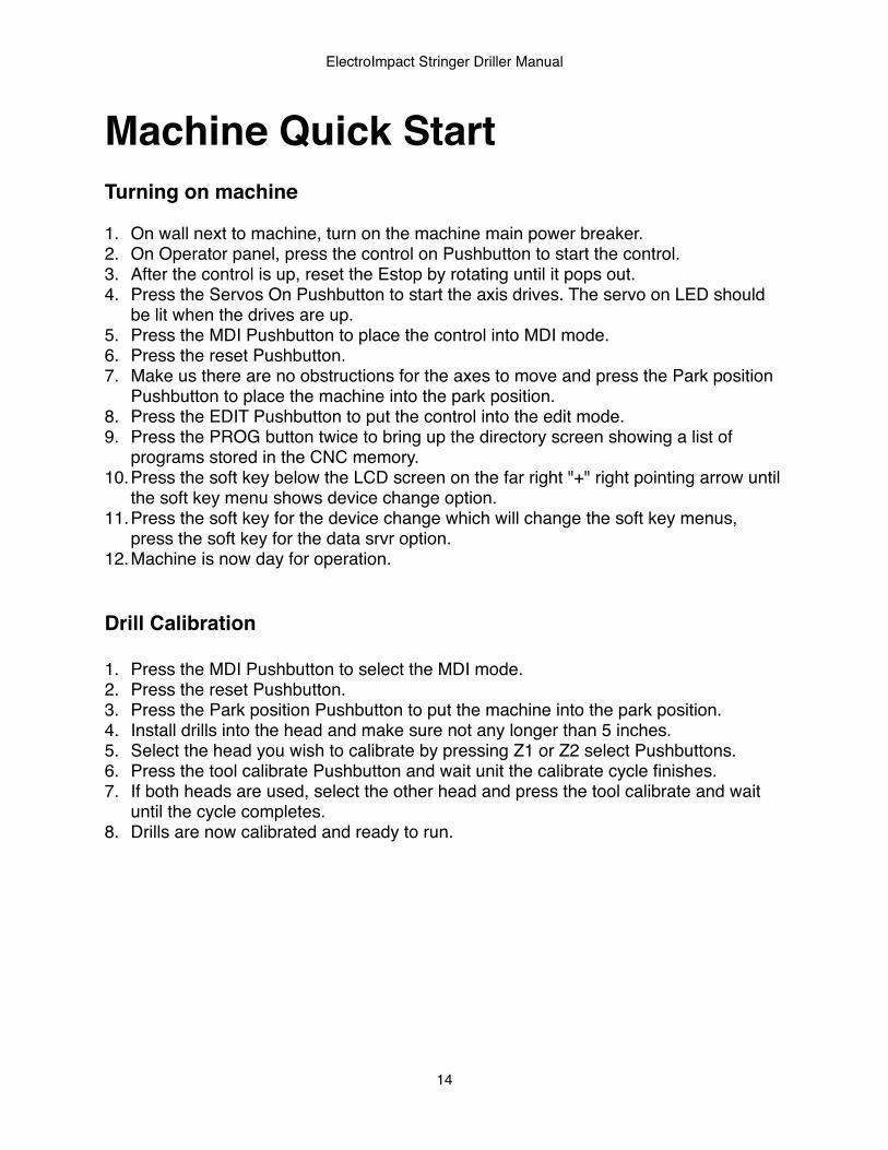
Machine Quick Start Turning on machine
1. On wall next to machine, turn on the machine main power breaker.2. On Operator panel, press the control on Pushbutton to start the control.3. After the control is up, reset the Estop by rotating until it pops out.4. Press the Servos On Pushbutton to start the axis drives. The servo on LED should
be lit when the drives are up.5. Press the MDI Pushbutton to place the control into MDI mode.6. Press the reset Pushbutton.7. Make us there are no obstructions for the axes to move and press the Park position
Pushbutton to place the machine into the park position.8. Press the EDIT Pushbutton to put the control into the edit mode.9. Press the PROG button twice to bring up the directory screen showing a list of
programs stored in the CNC memory.10.Press the soft key below the LCD screen on the far right "+" right pointing arrow until
the soft key menu shows device change option.11.Press the soft key for the device change which will change the soft key menus,
press the soft key for the data srvr option.12.Machine is now day for operation.
Drill Calibration
1. Press the MDI Pushbutton to select the MDI mode.2. Press the reset Pushbutton.3. Press the Park position Pushbutton to put the machine into the park position.4. Install drills into the head and make sure not any longer than 5 inches.5. Select the head you wish to calibrate by pressing Z1 or Z2 select Pushbuttons.6. Press the tool calibrate Pushbutton and wait unit the calibrate cycle finishes.7. If both heads are used, select the other head and press the tool calibrate and wait
until the cycle completes.8. Drills are now calibrated and ready to run.
ElectroImpact Stringer Driller Manual
14
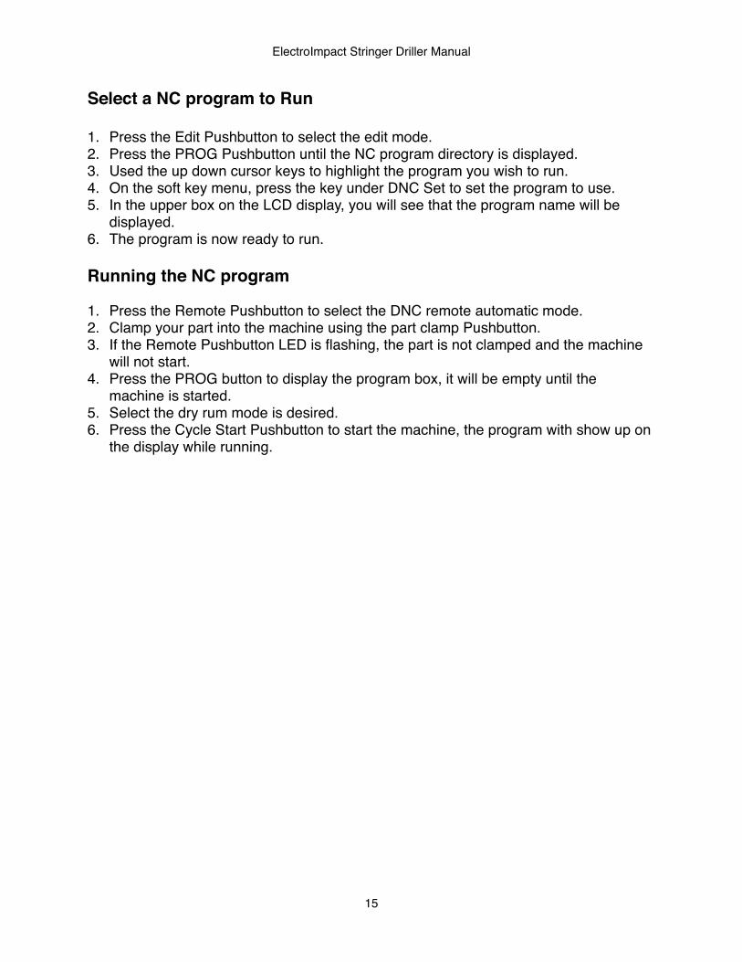
Select a NC program to Run
1. Press the Edit Pushbutton to select the edit mode.2. Press the PROG Pushbutton until the NC program directory is displayed.3. Used the up down cursor keys to highlight the program you wish to run.4. On the soft key menu, press the key under DNC Set to set the program to use.5. In the upper box on the LCD display, you will see that the program name will be
displayed.6. The program is now ready to run.
Running the NC program
1. Press the Remote Pushbutton to select the DNC remote automatic mode.2. Clamp your part into the machine using the part clamp Pushbutton.3. If the Remote Pushbutton LED is flashing, the part is not clamped and the machine
will not start.4. Press the PROG button to display the program box, it will be empty until the
machine is started.5. Select the dry rum mode is desired.6. Press the Cycle Start Pushbutton to start the machine, the program with show up on
the display while running.
ElectroImpact Stringer Driller Manual
15
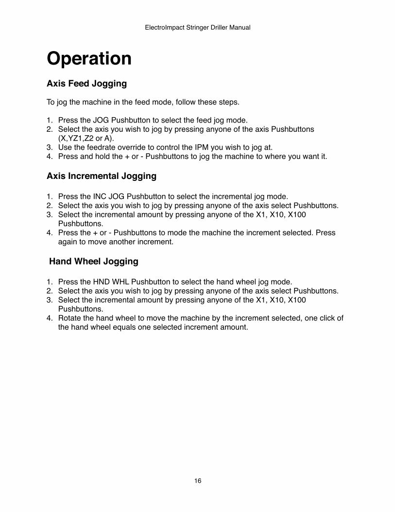
OperationAxis Feed Jogging
To jog the machine in the feed mode, follow these steps.
1. Press the JOG Pushbutton to select the feed jog mode.2. Select the axis you wish to jog by pressing anyone of the axis Pushbuttons
(X,YZ1,Z2 or A).3. Use the feedrate override to control the IPM you wish to jog at.4. Press and hold the + or - Pushbuttons to jog the machine to where you want it.
Axis Incremental Jogging
1. Press the INC JOG Pushbutton to select the incremental jog mode.2. Select the axis you wish to jog by pressing anyone of the axis select Pushbuttons.3. Select the incremental amount by pressing anyone of the X1, X10, X100
Pushbuttons.4. Press the + or - Pushbuttons to mode the machine the increment selected. Press
again to move another increment.
Hand Wheel Jogging
1. Press the HND WHL Pushbutton to select the hand wheel jog mode.2. Select the axis you wish to jog by pressing anyone of the axis select Pushbuttons.3. Select the incremental amount by pressing anyone of the X1, X10, X100
Pushbuttons.4. Rotate the hand wheel to move the machine by the increment selected, one click of
the hand wheel equals one selected increment amount.
ElectroImpact Stringer Driller Manual
16
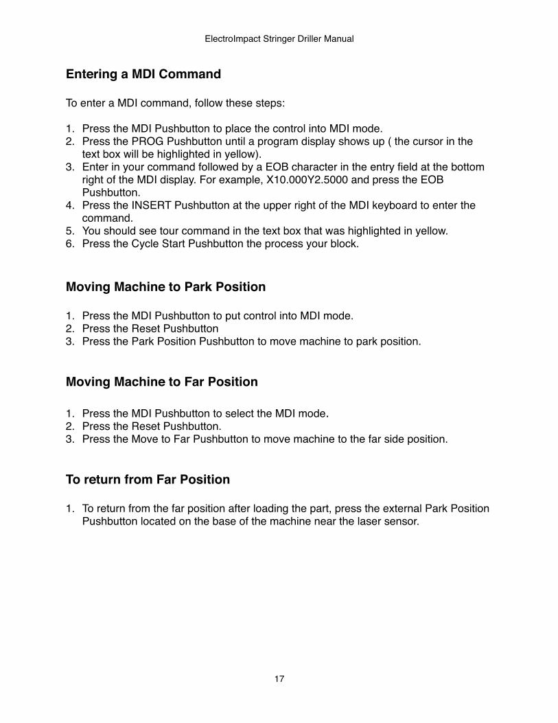
Entering a MDI Command
To enter a MDI command, follow these steps:
1. Press the MDI Pushbutton to place the control into MDI mode.2. Press the PROG Pushbutton until a program display shows up ( the cursor in the
text box will be highlighted in yellow).3. Enter in your command followed by a EOB character in the entry field at the bottom
right of the MDI display. For example, X10.000Y2.5000 and press the EOB Pushbutton.
4. Press the INSERT Pushbutton at the upper right of the MDI keyboard to enter the command.
5. You should see tour command in the text box that was highlighted in yellow.6. Press the Cycle Start Pushbutton the process your block.
Moving Machine to Park Position
1. Press the MDI Pushbutton to put control into MDI mode.2. Press the Reset Pushbutton3. Press the Park Position Pushbutton to move machine to park position.
Moving Machine to Far Position
1. Press the MDI Pushbutton to select the MDI mode.2. Press the Reset Pushbutton.3. Press the Move to Far Pushbutton to move machine to the far side position.
To return from Far Position
1. To return from the far position after loading the part, press the external Park Position Pushbutton located on the base of the machine near the laser sensor.
ElectroImpact Stringer Driller Manual
17
Calibrating Drill Heads
Drill calibration is used to set the height offsets for both of the drill heads for machine operation. The automatic cycle moves the machine to the Renishaw non contact laser to measure the position of the tip of the drill to the theoretical zero position of the Z axis datum.
To calibrate drill head 1, follow these steps:
1. Press the MDI Pushbutton to select the MDI mode.2. Press the Reset Pushbutton.3. Press the Park Position Pushbutton to move the machine to the park position.4. Load a drill less than 5.25" length into head 1.5. Press the Z1 Select Pushbutton to select head 1.6. Press the Tool Calibrate Pushbutton to run the automatic tool calibration.
To calibrate drill head 2, follow these steps:
1. Press the MDI Pushbutton to select the MDI mode.2. Press the Reset Pushbutton.3. Press the Park Position Pushbutton to move the machine to the park position.4. Load a drill less than 5.25" length into head 2.5. Press the Z2 Select Pushbutton to select head 2.6. Press the Tool Calibrate Pushbutton to run the automatic tool calibration.
If the tool calibrate cycle stops with the selected Z head in the down position at the laser X and Y position and/or the display screen shows the operator message screen, there is a error with the calibration. Press the far soft key (right pointing error) and press the soft key under the menu item OPER HIST to see the message. There are three types of alarm that are:
MACHINE NOT IN PARK POSITIONThis message is displayed when the tool calibration cycle is commanded when the machine is not in park position. Move the machine to the park position and retry calibrating the drill
NO TOOL PRESENTThis message is displayed when no tool was detected by the laser sensor. The drill may be too short as well. To clear, press the Cycle Start Pushbutton to finish the calibration routine and check the tool and retry.
TOOL TO LONGThis message is displayed when a tool longer than 5.25" has been detected by the laser sensor. To clear, press the Cycle Start Pushbutton to finish the routine and check the tool and retry.
ElectroImpact Stringer Driller Manual
18
Setting Up the DNC connection Before a program can be ran in the automatic cycle, it has to be selected and registered as a DNC program from the data server. The CNC control is connected through a Ethernet connection to a customer supplied PC that is running a FTP server to supply the NC programs to be run. When the CNC is first turned on, the operator must set up the data server as the default device. To set up the control to connect to the data FTP server, follow these steps:
1. Press the EDIT Pushbutton to select the edit mode.2. Press the PROG Pushbutton till you see a directory of files.3. Press the far right arrow soft key until one of the menu items reads DEVICE
CHANGE.4. Press the corresponding soft key and the menus will display new options.5. Find the soft key that is below the DATA SRVR and press it to select the data server. The FTP data server is now ready to be used for program operations.
Selecting a NC Program for Automatic Operation To run a program, a file from the server must be selected from the external PC and registered a a DNC program. To do this, follow these steps:
1. Press the Edit Pushbutton to select the edit mode.2. Press the PROG Pushbutton until the directory programs are displayed.3. Use the up/down arrow Pushbuttons on the MDI panel to highlight the program
name you wish to run.4. Use the soft key with the menu item (OPRT) displayed to change through the sub
menus until you see the menu item DNC SET.5. Press soft key for DNC SET and you will see in the upper box the program name as
registered for operation.
The control is now set up to run the selected program
Running a NC Program in Automatic Operation After the program has been registered for DNC operation, it can be ran in the automatic mode. Prior to starting the program, you can select the dry run option that will cause the program to rapid the drill to the feed start but wait for the operator to confirm or reject the current hole drilling operation. To run the NC program, follow these steps:
1. Press the Remote Pushbutton to set the automatic DNC operation mode.2. Select the dry run option if desired.
ElectroImpact Stringer Driller Manual
19
3. Press the Cycle Start Pushbutton to run the program. You will see the program show up in the program screen when it is started.
Aborting a Individual Drill Operation While the machine is running in the automatic mode and drilling the part, the operator may seen something that might not look right while the head is going down. The operator can pause the operation by pressing the yellow mushroom head Pushbutton located on the main head casting and the drilling operation will stop and the head that is being used will move back to to its top position. Looking at the operator panel, the LEDs for the skip drill and cont drill will be alternately flashing waiting for input from the operator. The two choices are:
Continue the Current Drill OperationPress the Cont Drill Pushbutton and the head will again rapid back to top of the part and then feed the drill in to process the hole.
Abort the Current Drill OperationPress the Skip Drill Pushbutton and the machine will move on to the next programmed hole location in the program.
Dry Run Operation When a new program is running or the operator wishes to check out the drilling operation without drilling the part, he can set the Dry Run option that will cause the machine to run as normal except that the machine will stop at R-Plane drill position. Looking at the operator panel, the LEDs for the skip drill and cont drill will be alternately flashing waiting for input from the operator. The two choices are:
Continue the Current Drill OperationPress the Cont Drill Pushbutton and the head will again rapid back to top of the part and then feed the drill in to process the hole.
Abort the Current Drill OperationPress the Skip Drill Pushbutton and the machine will move on to the next programmed hole location in the program.
The machine will continue this mode until the dry run mode is turned off by pressing the Dry Run Pushbutton to toggle it off.
ElectroImpact Stringer Driller Manual
20
ProgrammingProgramming DescriptionThe ElectroImpact machine uses customized programming blocks to control the drilling of parts based on the customers instructions. Several sub program macros perform the actual process and are described in this section.
Programming Address Commands
X CommandThis address sets the X axis position to be moved to.
Y CommandThis address sets the Y axis position to be moved to.
A CommandThis address sets the A axis position to be moved to.
B CommandThis address sets the R-Plane position of the selected head during the drill cycle.
S CommandThis address has different meanings depending on the type of M code it is used with. It can set the RPM of the spindle or set the drill stroke length.
M CommandThis address is used to call macro sub programs to process the part or to turn a machine function on or off.
G CommandThis address is a machine preparatory command and sets positioning modes.
ElectroImpact Stringer Driller Manual
21
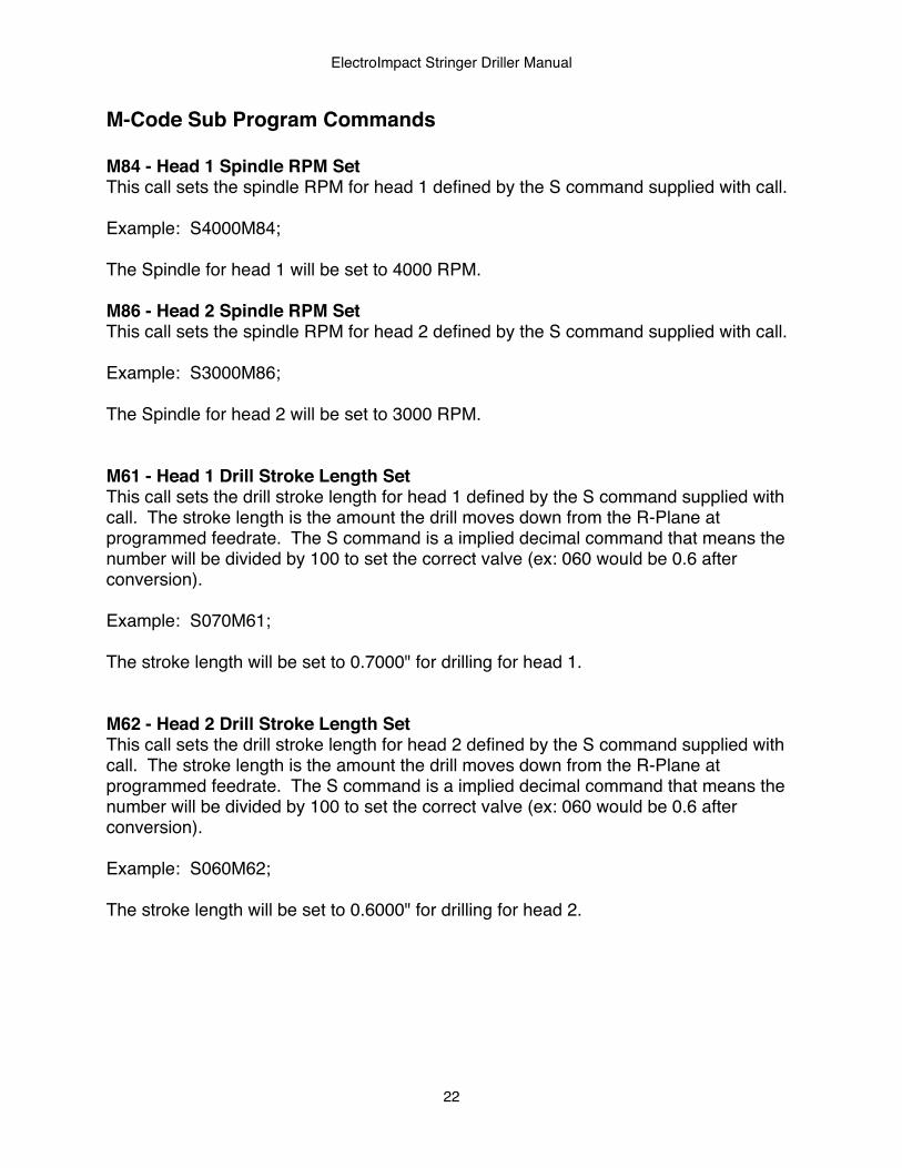
M-Code Sub Program Commands
M84 - Head 1 Spindle RPM SetThis call sets the spindle RPM for head 1 defined by the S command supplied with call.
Example: S4000M84;
The Spindle for head 1 will be set to 4000 RPM.
M86 - Head 2 Spindle RPM SetThis call sets the spindle RPM for head 2 defined by the S command supplied with call.
Example: S3000M86;
The Spindle for head 2 will be set to 3000 RPM.
M61 - Head 1 Drill Stroke Length SetThis call sets the drill stroke length for head 1 defined by the S command supplied with call. The stroke length is the amount the drill moves down from the R-Plane at programmed feedrate. The S command is a implied decimal command that means the number will be divided by 100 to set the correct valve (ex: 060 would be 0.6 after conversion).
Example: S070M61;
The stroke length will be set to 0.7000" for drilling for head 1.
M62 - Head 2 Drill Stroke Length SetThis call sets the drill stroke length for head 2 defined by the S command supplied with call. The stroke length is the amount the drill moves down from the R-Plane at programmed feedrate. The S command is a implied decimal command that means the number will be divided by 100 to set the correct valve (ex: 060 would be 0.6 after conversion).
Example: S060M62;
The stroke length will be set to 0.6000" for drilling for head 2.
ElectroImpact Stringer Driller Manual
22
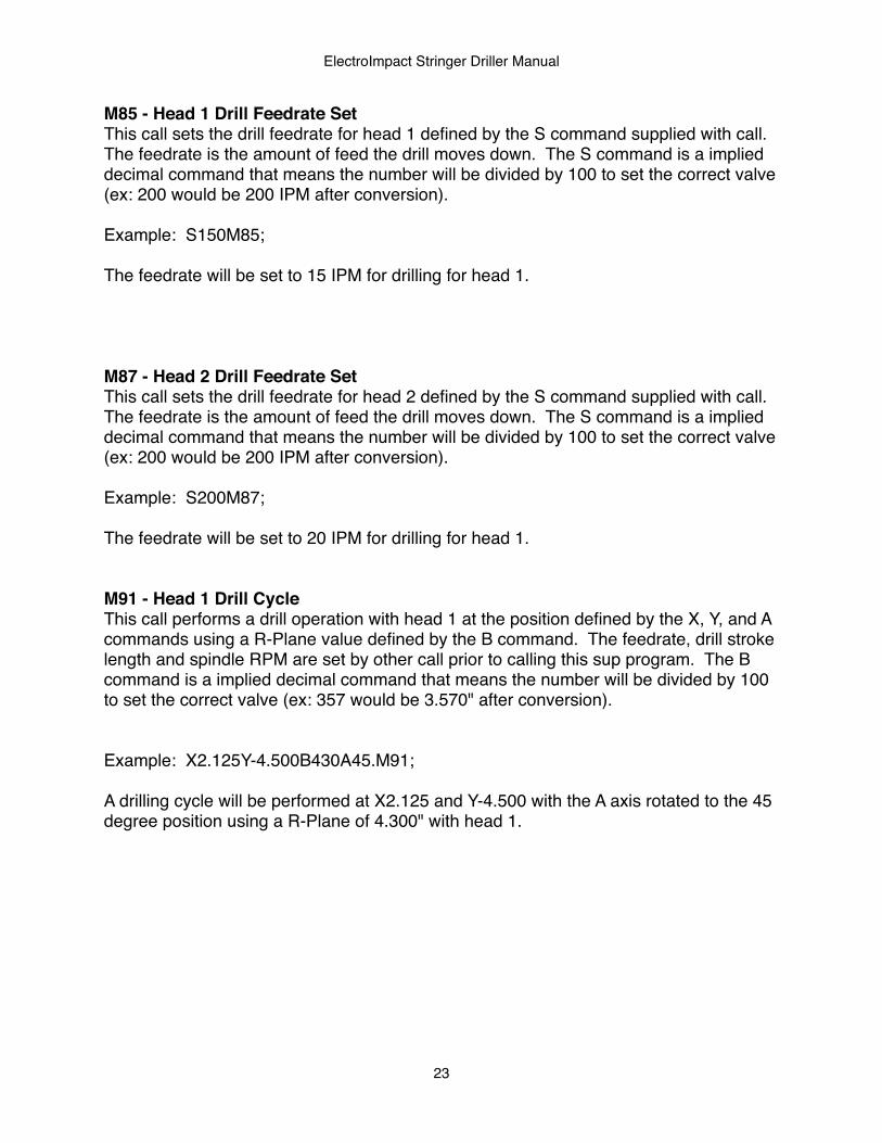
M85 - Head 1 Drill Feedrate SetThis call sets the drill feedrate for head 1 defined by the S command supplied with call. The feedrate is the amount of feed the drill moves down. The S command is a implied decimal command that means the number will be divided by 100 to set the correct valve (ex: 200 would be 200 IPM after conversion).
Example: S150M85;
The feedrate will be set to 15 IPM for drilling for head 1.
M87 - Head 2 Drill Feedrate SetThis call sets the drill feedrate for head 2 defined by the S command supplied with call. The feedrate is the amount of feed the drill moves down. The S command is a implied decimal command that means the number will be divided by 100 to set the correct valve (ex: 200 would be 200 IPM after conversion).
Example: S200M87;
The feedrate will be set to 20 IPM for drilling for head 1.
M91 - Head 1 Drill CycleThis call performs a drill operation with head 1 at the position defined by the X, Y, and A commands using a R-Plane value defined by the B command. The feedrate, drill stroke length and spindle RPM are set by other call prior to calling this sup program. The B command is a implied decimal command that means the number will be divided by 100 to set the correct valve (ex: 357 would be 3.570" after conversion).
Example: X2.125Y-4.500B430A45.M91;
A drilling cycle will be performed at X2.125 and Y-4.500 with the A axis rotated to the 45 degree position using a R-Plane of 4.300" with head 1.
ElectroImpact Stringer Driller Manual
23
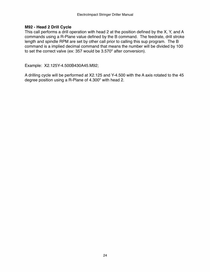
M92 - Head 2 Drill CycleThis call performs a drill operation with head 2 at the position defined by the X, Y, and A commands using a R-Plane value defined by the B command. The feedrate, drill stroke length and spindle RPM are set by other call prior to calling this sup program. The B command is a implied decimal command that means the number will be divided by 100 to set the correct valve (ex: 357 would be 3.570" after conversion).
Example: X2.125Y-4.500B430A45.M92;
A drilling cycle will be performed at X2.125 and Y-4.500 with the A axis rotated to the 45 degree position using a R-Plane of 4.300" with head 2.
ElectroImpact Stringer Driller Manual
24
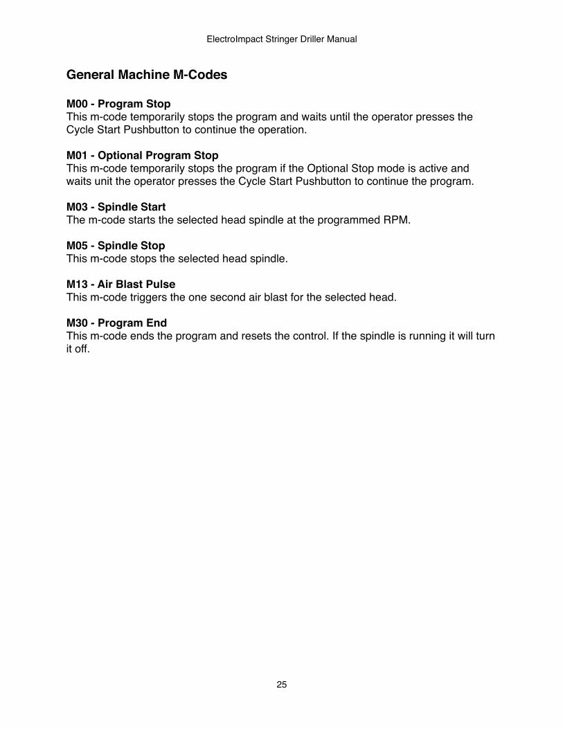
General Machine M-Codes
M00 - Program StopThis m-code temporarily stops the program and waits until the operator presses the Cycle Start Pushbutton to continue the operation.
M01 - Optional Program StopThis m-code temporarily stops the program if the Optional Stop mode is active and waits unit the operator presses the Cycle Start Pushbutton to continue the program.
M03 - Spindle StartThe m-code starts the selected head spindle at the programmed RPM.
M05 - Spindle StopThis m-code stops the selected head spindle.
M13 - Air Blast PulseThis m-code triggers the one second air blast for the selected head.
M30 - Program EndThis m-code ends the program and resets the control. If the spindle is running it will turn it off.
ElectroImpact Stringer Driller Manual
25
G-Code Preparatory Commands
G00 - Position ModeThis G-code sets the machine move in the rapid positioning mode.
G01 - Feed Position ModeThis G-code sets the machine to move in the feed mode with the feedrate set by a F command to set the IPM.
G91 - Incremental ModeThis G-code sets the machine in the incremental mode which meads the axis commands are considered to be delta move type commands.
G54 - Head 1 Work Coordinate OffsetThis G-code sets the machine work coordinate offset for head 1.
G55 - Head 2 Work Coordinate OffsetThis G-code sets the machine work coordinate offset for head 2.
G56 - Machine Work Coordinate OffsetThis G-code sets the machine work coordinate offset for the machine auto routines.
G92 - Absolute ModeThis G-code sets the machine in the absolute mode which means the axis commands are considered to be the end point of the commanded move.
ElectroImpact Stringer Driller Manual
26
MaintenanceSoftware ParametersDescription of Parameter TypesThere are 4 types of parameters used in the ElectroImpact drilling system. Each type controls a different section of the machine like the PMC, axis functions, and NC program options. These groups are:
Macro Variable Parameters:The macro variable are used to set different operating parameters of the NC and machine cycle programs. Example of these include values that control tool calibration system, park positions, maximum spindle speeds. See the Macro variable descriptions in the appendix.
Fanuc System Parameters:The Fanuc system parameters control how the CNC works internally. These parameters control axis resolution factors, position switch functions, axis names etc. See the Fanuc 0i-MD Parameters manual for descriptions.
Keep Relays:The keep relays are used to turn on and off functions internal to the CNC ladder. They are mainly used to control functions of the machine and used for maintenance of the machine. Some of the systems controlled by the keep relays are drill systems enable and park clamp switch bypass. See the keep relay description in the appendix section.
Spindle Head Offset Parameters:The Spindle Head offset parameters are used to set the coordinate systems for each of the drill head for the X and Y axes. The Z1 and Z2 and automatically set by the laser calibration macro programs. These work offsets are:
! G54! Drill Head 1 coordinate system! G55! Drill Head 2 coordinate system! G56! Park and Calibration routine coordinate system
ElectroImpact Stringer Driller Manual
27
Setting Macro Variable ParametersFor a description of these parameters, look n the appendix of this manual. To change a macro variable parameter, follow these steps:
1. Using the mouse, click on the OFST screen select button (small window below the main Fanuc CNC screen) to change to the offset screen.
2. Press the MDI pushbutton on the operator control panel to change to MDI mode.3. Using the soft keys located at the bottom of the Fanuc CNC screen, click on the +
key at the far bottom right until one of the soft key buttons labels show MACRO.4. Click on the MACRO soft key to bring up the variable list. A list of values will appear
with the macro numbers.5. Using the up and down arrow or page keys, highlight the macro number you wish to
change (yellow highlight).6. Using the keyboard, enter the number you wish to replace the value highlighted and
press enter.
Setting Fanuc System ParametersFor a description of these parameters, refer to the Fanuc 30i Parameter manual. To change a system parameter follow these steps:
1. Press the MDI pushbutton on the operator control panel to change to the MDI mode.2. Using the mouse, click on the OFST screen select button (small window below the
main Fanuc CNC screen) to change to the offset screen. 3. Using the soft keys located at the bottom of the Fanuc CNC screen, click on the +
key at the far bottom right until one of the soft key buttons labels show SETTINGS.4. Using the arrow keys, highlight the Parameter Write Enable and enter 1 and press
enter on the keyboard to allow system parameters to be edited (an alarm message will appear saying parameter write enabled).
5. Using the mouse, click on the SYS screen select button (small window below the main Fanuc CNC screen) to change to the parameter screen.
6. Click on the PARAM soft key.7. Using the arrow and page keys, highlight the parameter you wish to change. You
can search for a parameter number by entering the number and clicking on the NO. SRH soft key.
8. Using the keyboard, enter the number you wish to replace the value highlighted and press enter.
9. Using the mouse, click on the OFST screen select button (small window below the main Fanuc CNC screen) to change to the offset screen.
ElectroImpact Stringer Driller Manual
28
10.Using the soft keys located at the bottom of the Fanuc CNC screen, click on the + key at the far bottom right until one of the soft key buttons labels show SETTINGS.
11.Using the arrow keys, highlight the Parameter Write Enable and enter 0 and press enter on the keyboard to turn off parameter edit.
12.Press the RESET pushbutton to clear the parameter write alarm.
Warning: Incorrect settings of the system parameters can cause damage to the machine and injury to the operator. Caution should be used when changing these parameters.
Setting Keep RelaysFor a description of the keep relays, look n the appendix of this manual. To change a keep relay, follow these steps:
1. Press the MDI pushbutton on the operator control panel to change to the MDI mode. 2. Using the mouse, click on the SYS screen select button (small window below the
main Fanuc CNC screen) to change to the parameter screen. 3. Using the soft keys located at the bottom of the Fanuc CNC screen, click on the +
key at the far bottom right until one of the soft key buttons labels show PMC MAINTENANCE.
4. Click on the PMC MAINTENANCE soft key. 5. Click on the + key at the lower right until one of the soft key button labels show
KEEP. 6. Click on the KEEP soft key and the display will change to the keep relay screen.
Using the arrow keys, highlight the keep relay bit field you wish to edit. 7. Using the keyboard, enter a 1 or 0 and press enter to change the keep relay bit.
Warning: Keep relays enable and disable sections of the PMC Ladder code and caution should be used when changing these relays.
Setting FME Work Offset ParametersFor a description of these parameters, refer to the Fanuc 30i Operator manual. To change a FME work zone offset, follow these steps:
1. Press the MDI pushbutton on the operator control panel to change to the MDI mode. 2. Using the mouse, click on the OFST screen select button (small window below the
main Fanuc CNC screen) to change to the offset screen. 3. Using the soft keys located at the bottom of the Fanuc CNC screen, click on the +
key at the far bottom right until one of the soft key buttons labels show WORK.
ElectroImpact Stringer Driller Manual
29

4. Click on the WORK soft key to bring up the work zone offset groups. They are labeled G54,G55,G56,G57,G58 and G59 and have an offset field for each of the major axes. Using the arrow keys, highlight the data group you wish to edit.
5. Using the arrow keys, highlight the axis offset you wish to edit. 6. Using the keyboard, enter the number you wish to replace the value highlighted and
press enter.
Warning: These offsets locate the home datum for each of the FME stations and incorrect setting can cause damage to the machine.
ElectroImpact Stringer Driller Manual
30
Machine Datum AlignmentX and Y Alignment Procedure
The machine uses absolute encoders and does not need to referenced even if the machine powered off. If there is need to remove the X or Y axis for machine repair or a new motor, the machine will have to be referenced to the datum of the machine. The Z axes are not set by this procedure as they are calculated by the laser calibration routines. On the machine on the rotating bar there is a block that the part rests up against for normal operations. In this block there is a .75 diameter hole that a indicator can be used to find the center and establish the machine reference. The actual datum is the the left bubbled edge for the x axis (1.5000 inches from the centerline of the datum hole) and the center of the datum hole for the Y axis. Before the alignment can be done, we will describe the coordinate systems used by the machine.
The machine has it own master machine coordinate system that shows the absolute position of the machine. This coordinate system is label machine coordinates and can be viewed in the position of the screen. The relative or normal position is a position that is offset by the control and is set to be the datum to the first head and this coordinate offset is the G54 work coordinate offset. Normally when the drill of the first head is directly over the datum location, the display of the relative coordinates will read x0.0000 and Y0.0000 and the machine coordinates will read a positive dimension ( for example, X9.3421 and Y8.7382). The G54 coordinate selection is generally automatically selected and if the control is reset, it will be selected.
To align the X and Y axes, follow these steps:
1. Goto the work coordinate offsets page and using the arrow keys, find the original X and Y offsets for the G54 zone and write them down.
2. Place a indicator capable of indicating the .75 datum hole into head 1.3. Using the manual mode, indicate head 1 to the centerline of the hole.4. Note the positions that the axes are at and move the X axis 1.5 inches positive from
the indicated datum hole. This will place the machine at the true program datum.5. Depending on which axis you are aligning of if both, move the axis incrementally
from the datum the amount written down in step 1 in the minus direction. For example, if the X is the one off, subtract the offset value in X from the machine position (offset value = 9.1234, the machine position = 1.1234, 1.1234 - 9.1234 = -8.000). Move the X axis to the X-8.000 position and this will be the machine position true zero. You might have to temporarily set the soft stroke limit to allow the motion.
6. Goto the system parameter 1815 bit 4. Set this 0 and then back to 1 for the axis you are aligning. You will get a error message when you change it to 0.
7. Estop the machine and then turn it off.8. Turn the control back on and after it boots up, verify that the Axis you are aligning
machine position is at 0.0000.
ElectroImpact Stringer Driller Manual
31
Z1 and Z2 Alignment Procedure
The two drill axes usually have their respective offsets set by the tool calibration routine but if the head has been removed or the axis motor has been replace, the top up position of the axis must be zeroed to set the machine position. Since the axes are calibrated by the laser, the alignment just has to be close to the 0 position. There are two ways to set these that are, Alignment to the other head and alignment to the upper hard limit switch.
Alignment to the Other HeadThis is the easiest way to set the zero for the drill head and utilizes the position of the other head. Follow these steps:
1. Make sure the other head is at the machine position 0.0000, not the relative position.2. Jog the head that you wish to align and using the bottom of the servo motor
aluminum belt box to line up with the other head.3. Put the machine into Estop.4. Display the system parameters and toto parameter 1815, bit 4. Highlight the head
that is to be aligned and set the bit to 0 and back to 1. You will get an alarm message doing this.
5. Turn the control off and then back on.6. Wait till it boots and verify that the head you aligned is at 0.0000 machine position.
Alignment to the Hard LimitThis method uses the hard limits to set to head zero position. To use this method, Follow these steps:
1. Locate the plus over travel relay for the head you wish to align and use the lever to force it on. Note: this disables the hard limit, use care when moving the slide.
2. Have a helper watch the over travel relay light and jog the head up until the light goes out on the relay indicating the hard limit has be triggered.
3. Jog the head back down slowly until the light comes on once again.4. Move the machine incrementally down .1" more.5. Put the machine into Estop.6. Display the system parameters and toto parameter 1815, bit 4. Highlight the head
that is to be aligned and set the bit to 0 and back to 1. You will get an alarm message doing this.
7. Turn the control off and then back on.8. Wait till it boots and verify that the head you aligned is at 0.0000 machine position.
ElectroImpact Stringer Driller Manual
32
AppendixFanuc Keep RelaysK0.0! Disable Spindle Drill Head 1This keep bit is used to disable circuit breaker alarms, Maintenance purposes only
K0.1! Disable Spindle Drill Head 2This bit enables the Schmidt Servo Press logic (diagnostic purposes only).
K0.2! Spare
K0.3! Spare
K0.4! Spare
K0.5! Spare
K0.6! Spare
K0.7! Spare
K1.0! Clamp Switch 1 Bypass Keep RelayThis bit disables the clamp switch for the selected zone.
K1.1! Clamp Switch 2 Bypass Keep RelayThis bit disables the clamp switch for the selected zone.
K1.2! Clamp Switch 3 Bypass Keep RelayThis bit disables the clamp switch for the selected zone.
K1.3! Clamp Switch 4 Bypass Keep RelayThis bit disables the clamp switch for the selected zone.
K1.4! Clamp Switch 5 Bypass Keep RelayThis bit disables the clamp switch for the selected zone.
K1.5! Clamp Switch 6 Bypass Keep RelayThis bit disables the clamp switch for the selected zone.
K1.6! Clamp Switch 7Bypass Keep RelayThis bit disables the clamp switch for the selected zone.
K1.7! Clamp Switch 8 Bypass Keep RelayThis bit disables the clamp switch for the selected zone. retracted interlocks.
ElectroImpact Stringer Driller Manual
33
K2.0! Clamp Switch 9 Bypass Keep RelayThis bit disables the clamp switch for the selected zone.
K2.1! Clamp Switch10 Bypass Keep RelayThis bit disables the clamp switch for the selected zone.
K2.2! Clamp Switch 11 Bypass Keep RelayThis bit disables the clamp switch for the selected zone.
K2.3! Clamp Switch 12 Bypass Keep RelayThis bit disables the clamp switch for the selected zone.
K2.4! Clamp Switch 13 Bypass Keep RelayThis bit disables the clamp switch for the selected zone.
K2.5! Clamp Switch 14 Bypass Keep RelayThis bit disables the clamp switch for the selected zone.
K2.6! Clamp Switch 15 Bypass Keep RelayThis bit disables the clamp switch for the selected zone.
K2.7! Clamp Switch 16 Bypass Keep RelayThis bit disables the clamp switch for the selected zone.
ElectroImpact Stringer Driller Manual
34
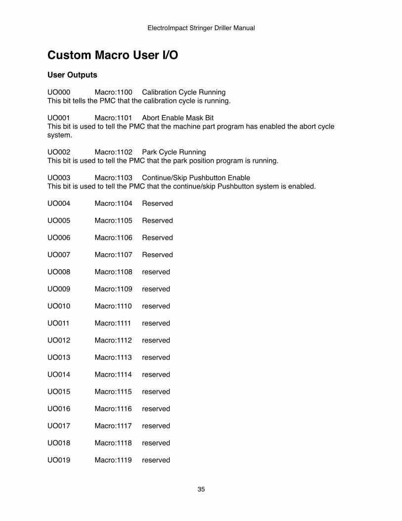
Custom Macro User I/OUser Outputs
UO000!! Macro:1100! Calibration Cycle RunningThis bit tells the PMC that the calibration cycle is running.
UO001!! Macro:1101! Abort Enable Mask BitThis bit is used to tell the PMC that the machine part program has enabled the abort cycle system.
UO002!! Macro:1102! Park Cycle RunningThis bit is used to tell the PMC that the park position program is running.
UO003!! Macro:1103! Continue/Skip Pushbutton EnableThis bit is used to tell the PMC that the continue/skip Pushbutton system is enabled.
UO004!! Macro:1104! Reserved
UO005!! Macro:1105! Reserved
UO006!! Macro:1106! Reserved
UO007!! Macro:1107! Reserved
UO008!! Macro:1108! reserved
UO009!! Macro:1109! reserved
UO010!! Macro:1110! reserved
UO011!! Macro:1111! reserved
UO012!! Macro:1112! reserved
UO013!! Macro:1113! reserved
UO014!! Macro:1114! reserved
UO015!! Macro:1115! reserved
UO016!! Macro:1116! reserved
UO017!! Macro:1117! reserved
UO018!! Macro:1118! reserved
UO019!! Macro:1119! reserved
ElectroImpact Stringer Driller Manual
35
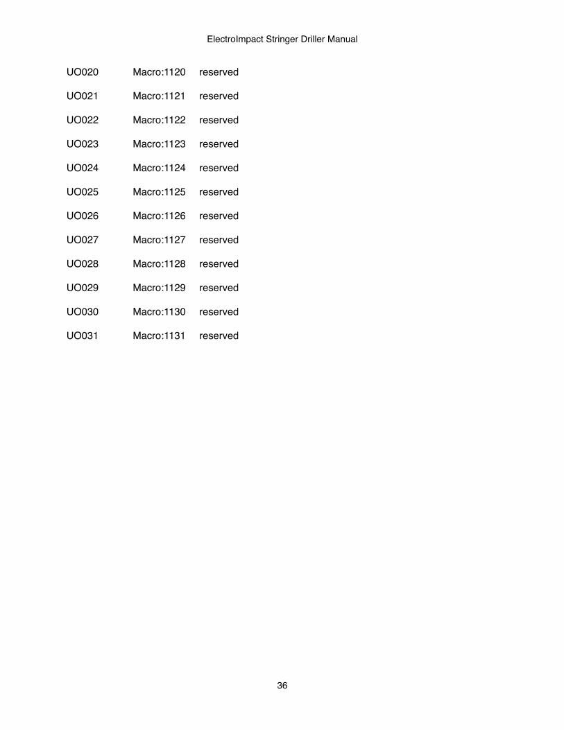
UO020!! Macro:1120! reserved
UO021!! Macro:1121! reserved
UO022!! Macro:1122! reserved
UO023!! Macro:1123! reserved
UO024!! Macro:1124! reserved
UO025!! Macro:1125! reserved
UO026!! Macro:1126! reserved
UO027!! Macro:1127! reserved
UO028!! Macro:1128! reserved
UO029!! Macro:1129! reserved
UO030!! Macro:1130! reserved
UO031!! Macro:1131! reserved
ElectroImpact Stringer Driller Manual
36

User Inputs
UI000! ! Macro:1000! Part Present signalThis bit is used to tell the CNC part program that a part is present in the machine
UI001! ! Macro:1001! Air On SignalThis bit is used to tell the CNC part program that the machine has system air pressure.
UI002! ! Macro:1002! Part Clamped SignalThis bit is used to tell the CNC part program that a part is clamped into the machine.
UI003! ! Macro:1003! Spindle 1 is Disabled SignalThis bit is used to tell the CNC part program that spindle drill head 1 has been disabled through the PLC.
UI004! ! Macro:1004! Spindle 2 is Disabled SignalThis bit is used to tell the CNC part program that the spindle drill head 2 has been disabled through the PLC.
UI005! ! Macro:1005! Machine at Park PositionThis bit is used to tell the CNC part program that the machine is at the park position.
UI006! ! Macro:1006! Spindle 1 is Running SignalThis bit is used to tell the CNC part program that head 1 spindle is running.
UI007! ! Macro:1007! Spindle 2 is Running SignalThis bit is used to tell the CNC part program that head 2 spindle is running.
UI008! ! Macro:1008! Continue Cycle Pushbutton StatusThis bit is used to tell the NC program that the Continue cycle Pushbutton status.
UI009! ! Macro:1009! Skip Cycle Pushbutton StatusThis bit is used by tell the NC program that the skip cycle Pushbutton status.
UI010! ! Macro:1010! Spindle Head Selection Status SignalThis bit tells the CNC part program which spindle head has been selected (0=head 1, 1=head 2).
UI011! ! Macro:1011! Dry Run Active StatusThis bit tells the CNC part program that the dry run mode is active.
UI012! ! Macro:1012! Not Used
UI013! ! Macro:1013! Not Used
UI014! ! Macro:1014! Not Used
UI015! ! Macro:1015! Not Used
ElectroImpact Stringer Driller Manual
37
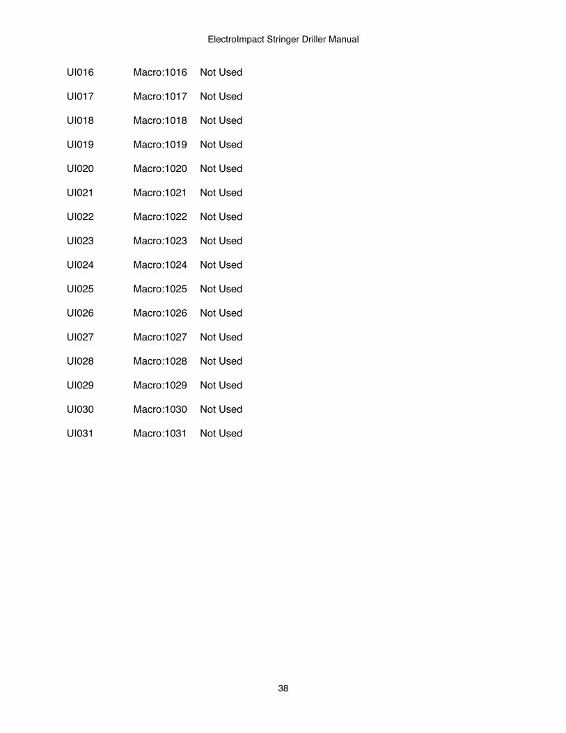
UI016! ! Macro:1016! Not Used
UI017! ! Macro:1017! Not Used
UI018! ! Macro:1018! Not Used
UI019! ! Macro:1019! Not Used
UI020! ! Macro:1020! Not Used
UI021! ! Macro:1021! Not Used
UI022! ! Macro:1022! Not Used
UI023! ! Macro:1023! Not Used
UI024! ! Macro:1024! Not Used
UI025! ! Macro:1025! Not Used
UI026! ! Macro:1026! Not Used
UI027! ! Macro:1027! Not Used
UI028! ! Macro:1028! Not Used
UI029! ! Macro:1029! Not Used
UI030! ! Macro:1030! Not Used
UI031! ! Macro:1031! Not Used
ElectroImpact Stringer Driller Manual
38
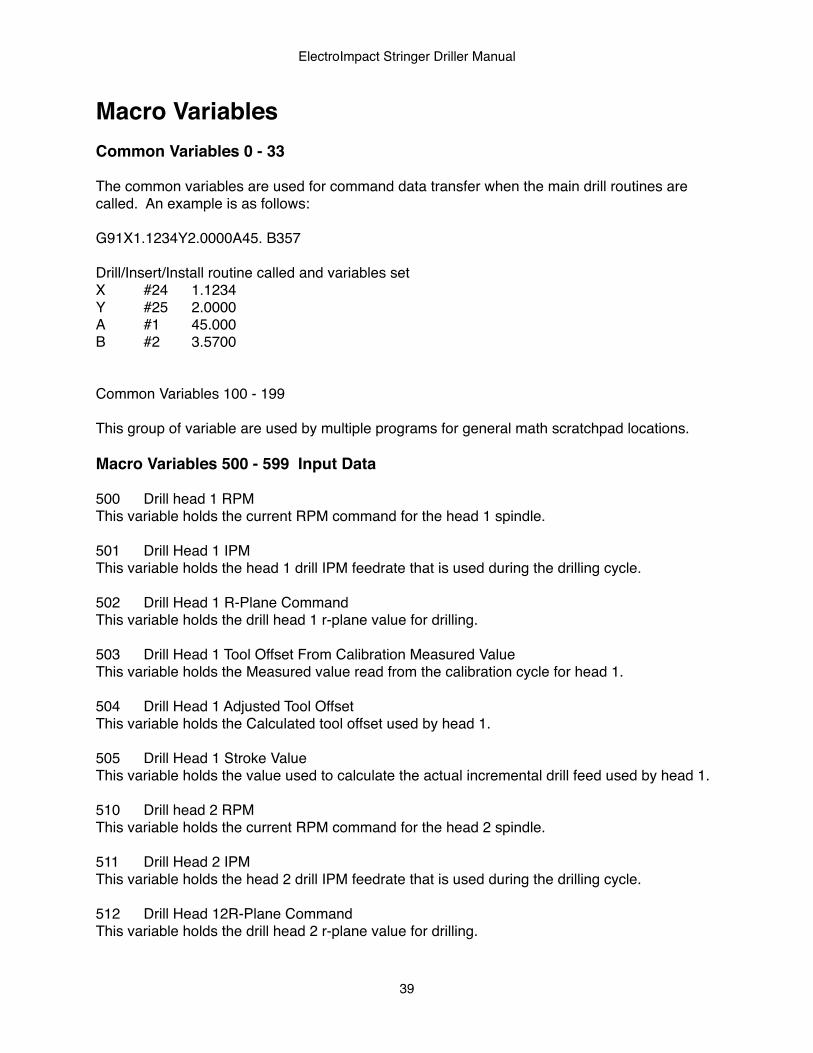
Macro VariablesCommon Variables 0 - 33
The common variables are used for command data transfer when the main drill routines are called. An example is as follows:
G91X1.1234Y2.0000A45. B357
Drill/Insert/Install routine called and variables setX! #24! 1.1234Y! #25! 2.0000A! #1! 45.000B! #2! 3.5700
Common Variables 100 - 199
This group of variable are used by multiple programs for general math scratchpad locations.
Macro Variables 500 - 599 Input Data
500! Drill head 1 RPM!This variable holds the current RPM command for the head 1 spindle.
501! Drill Head 1 IPMThis variable holds the head 1 drill IPM feedrate that is used during the drilling cycle.
502! Drill Head 1 R-Plane CommandThis variable holds the drill head 1 r-plane value for drilling.
503! Drill Head 1 Tool Offset From Calibration Measured ValueThis variable holds the Measured value read from the calibration cycle for head 1.
504! Drill Head 1 Adjusted Tool OffsetThis variable holds the Calculated tool offset used by head 1.
505! Drill Head 1 Stroke ValueThis variable holds the value used to calculate the actual incremental drill feed used by head 1.
510! Drill head 2 RPM!This variable holds the current RPM command for the head 2 spindle.
511! Drill Head 2 IPMThis variable holds the head 2 drill IPM feedrate that is used during the drilling cycle.
512! Drill Head 12R-Plane CommandThis variable holds the drill head 2 r-plane value for drilling.
ElectroImpact Stringer Driller Manual
39
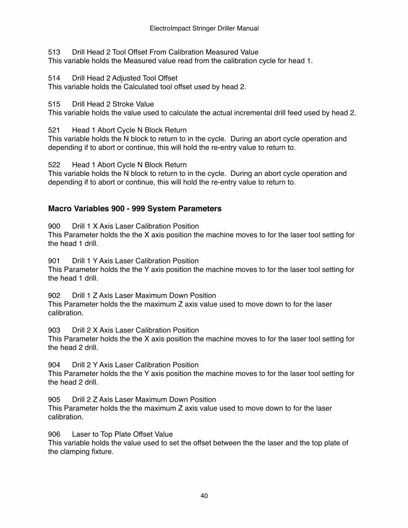
513! Drill Head 2 Tool Offset From Calibration Measured ValueThis variable holds the Measured value read from the calibration cycle for head 1.
514! Drill Head 2 Adjusted Tool OffsetThis variable holds the Calculated tool offset used by head 2.
515! Drill Head 2 Stroke ValueThis variable holds the value used to calculate the actual incremental drill feed used by head 2.
521! Head 1 Abort Cycle N Block ReturnThis variable holds the N block to return to in the cycle. During an abort cycle operation and depending if to abort or continue, this will hold the re-entry value to return to.
522! Head 1 Abort Cycle N Block ReturnThis variable holds the N block to return to in the cycle. During an abort cycle operation and depending if to abort or continue, this will hold the re-entry value to return to.
Macro Variables 900 - 999 System Parameters
900! Drill 1 X Axis Laser Calibration PositionThis Parameter holds the the X axis position the machine moves to for the laser tool setting for the head 1 drill.
901! Drill 1 Y Axis Laser Calibration PositionThis Parameter holds the the Y axis position the machine moves to for the laser tool setting for the head 1 drill.
902! Drill 1 Z Axis Laser Maximum Down PositionThis Parameter holds the the maximum Z axis value used to move down to for the laser calibration.
903! Drill 2 X Axis Laser Calibration PositionThis Parameter holds the the X axis position the machine moves to for the laser tool setting for the head 2 drill.
904! Drill 2 Y Axis Laser Calibration PositionThis Parameter holds the the Y axis position the machine moves to for the laser tool setting for the head 2 drill.
905! Drill 2 Z Axis Laser Maximum Down PositionThis Parameter holds the the maximum Z axis value used to move down to for the laser calibration.
906! Laser to Top Plate Offset ValueThis variable holds the value used to set the offset between the the laser and the top plate of the clamping fixture.
ElectroImpact Stringer Driller Manual
40
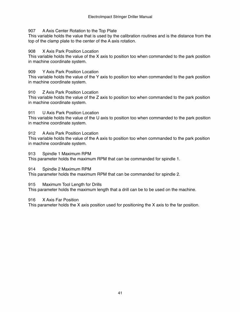
907! A Axis Center Rotation to the Top PlateThis variable holds the value that is used by the calibration routines and is the distance from the top of the clamp plate to the center of the A axis rotation.
908! X Axis Park Position LocationThis variable holds the value of the X axis to position too when commanded to the park position in machine coordinate system.
909! Y Axis Park Position LocationThis variable holds the value of the Y axis to position too when commanded to the park position in machine coordinate system.
910! Z Axis Park Position LocationThis variable holds the value of the Z axis to position too when commanded to the park position in machine coordinate system.
911! U Axis Park Position LocationThis variable holds the value of the U axis to position too when commanded to the park position in machine coordinate system.
912! A Axis Park Position LocationThis variable holds the value of the A axis to position too when commanded to the park position in machine coordinate system.
913! Spindle 1 Maximum RPM This parameter holds the maximum RPM that can be commanded for spindle 1.
914! Spindle 2 Maximum RPM This parameter holds the maximum RPM that can be commanded for spindle 2.
915! Maximum Tool Length for DrillsThis parameter holds the maximum length that a drill can be to be used on the machine.
916! X Axis Far PositionThis parameter holds the X axis position used for positioning the X axis to the far position.
ElectroImpact Stringer Driller Manual
41
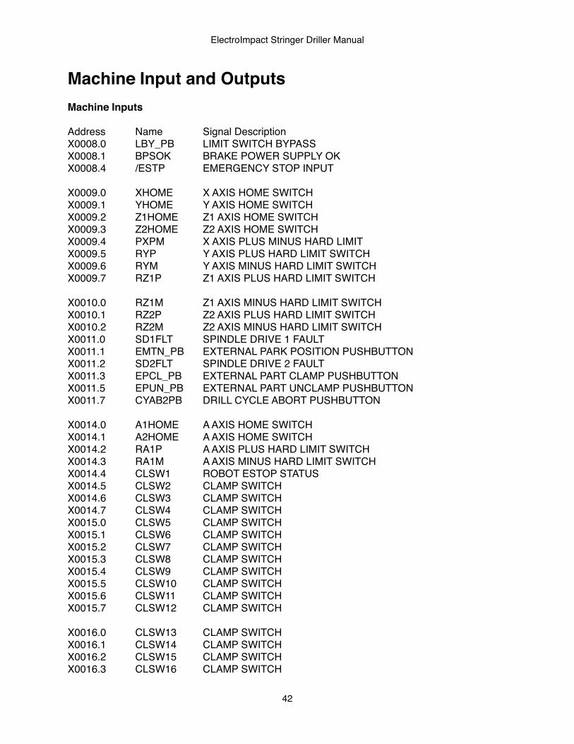
Machine Input and OutputsMachine Inputs
Address! Name! ! Signal DescriptionX0008.0! LBY_PB! LIMIT SWITCH BYPASS X0008.1! BPSOK! BRAKE POWER SUPPLY OKX0008.4! /ESTP! ! EMERGENCY STOP INPUT
X0009.0! XHOME! X AXIS HOME SWITCHX0009.1! YHOME! Y AXIS HOME SWITCHX0009.2! Z1HOME! Z1 AXIS HOME SWITCHX0009.3! Z2HOME! Z2 AXIS HOME SWITCHX0009.4! PXPM! ! X AXIS PLUS MINUS HARD LIMITX0009.5! RYP! ! Y AXIS PLUS HARD LIMIT SWITCHX0009.6! RYM! ! Y AXIS MINUS HARD LIMIT SWITCHX0009.7! RZ1P! ! Z1 AXIS PLUS HARD LIMIT SWITCH
X0010.0! RZ1M! ! Z1 AXIS MINUS HARD LIMIT SWITCHX0010.1! RZ2P! ! Z2 AXIS PLUS HARD LIMIT SWITCHX0010.2! RZ2M! ! Z2 AXIS MINUS HARD LIMIT SWITCHX0011.0! SD1FLT! SPINDLE DRIVE 1 FAULT! !X0011.1! EMTN_PB ! EXTERNAL PARK POSITION PUSHBUTTONX0011.2! SD2FLT! SPINDLE DRIVE 2 FAULTX0011.3! EPCL_PB! EXTERNAL PART CLAMP PUSHBUTTONX0011.5! EPUN_PB! EXTERNAL PART UNCLAMP PUSHBUTTONX0011.7! CYAB2PB ! DRILL CYCLE ABORT PUSHBUTTON
X0014.0! A1HOME! A AXIS HOME SWITCH! !X0014.1! A2HOME! A AXIS HOME SWITCH! !X0014.2! RA1P! ! A AXIS PLUS HARD LIMIT SWITCH!X0014.3! RA1M! ! A AXIS MINUS HARD LIMIT SWITCHX0014.4! CLSW1! ROBOT ESTOP STATUSX0014.5! CLSW2! CLAMP SWITCHX0014.6! CLSW3! CLAMP SWITCHX0014.7! CLSW4! CLAMP SWITCHX0015.0! CLSW5! CLAMP SWITCHX0015.1! CLSW6! CLAMP SWITCHX0015.2! CLSW7! CLAMP SWITCHX0015.3! CLSW8! CLAMP SWITCHX0015.4! CLSW9! CLAMP SWITCHX0015.5! CLSW10! CLAMP SWITCHX0015.6! CLSW11! CLAMP SWITCHX0015.7! CLSW12! CLAMP SWITCH
X0016.0! CLSW13! CLAMP SWITCHX0016.1! CLSW14! CLAMP SWITCHX0016.2! CLSW15! CLAMP SWITCHX0016.3! CLSW16! CLAMP SWITCH
ElectroImpact Stringer Driller Manual
42
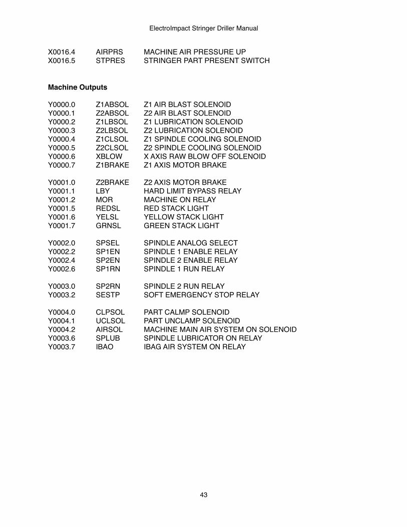
X0016.4! AIRPRS ! MACHINE AIR PRESSURE UP!X0016.5! STPRES ! STRINGER PART PRESENT SWITCH
Machine Outputs
Y0000.0! Z1ABSOL! Z1 AIR BLAST SOLENOIDY0000.1! Z2ABSOL! Z2 AIR BLAST SOLENOIDY0000.2! Z1LBSOL! Z1 LUBRICATION SOLENOIDY0000.3! Z2LBSOL! Z2 LUBRICATION SOLENOIDY0000.4! Z1CLSOL! Z1 SPINDLE COOLING SOLENOIDY0000.5! Z2CLSOL! Z2 SPINDLE COOLING SOLENOIDY0000.6! XBLOW! X AXIS RAW BLOW OFF SOLENOIDY0000.7! Z1BRAKE! Z1 AXIS MOTOR BRAKE
Y0001.0! Z2BRAKE! Z2 AXIS MOTOR BRAKEY0001.1! LBY! ! HARD LIMIT BYPASS RELAYY0001.2! MOR! ! MACHINE ON RELAYY0001.5! REDSL! RED STACK LIGHTY0001.6! YELSL!! YELLOW STACK LIGHTY0001.7! GRNSL! GREEN STACK LIGHT! ! !
Y0002.0! SPSEL!! SPINDLE ANALOG SELECTY0002.2! SP1EN! SPINDLE 1 ENABLE RELAYY0002.4! SP2EN! SPINDLE 2 ENABLE RELAYY0002.6! SP1RN! SPINDLE 1 RUN RELAY
Y0003.0! SP2RN! SPINDLE 2 RUN RELAYY0003.2! SESTP! SOFT EMERGENCY STOP RELAY
Y0004.0! CLPSOL! PART CALMP SOLENOIDY0004.1! UCLSOL! PART UNCLAMP SOLENOIDY0004.2! AIRSOL! MACHINE MAIN AIR SYSTEM ON SOLENOIDY0003.6! SPLUB ! SPINDLE LUBRICATOR ON RELAYY0003.7! IBAO ! ! IBAG AIR SYSTEM ON RELAY
ElectroImpact Stringer Driller Manual
43
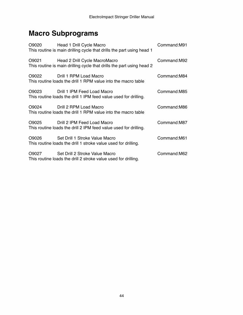
Macro SubprogramsO9020!! Head 1 Drill Cycle Macro! ! ! ! Command:M91This routine is main drilling cycle that drills the part using head 1
O9021!! Head 2 Drill Cycle MacroMacro! ! ! Command:M92This routine is main drilling cycle that drills the part using head 2
O9022!! Drill 1 RPM Load Macro! ! ! ! Command:M84This routine loads the drill 1 RPM value into the macro table
O9023!! Drill 1 IPM Feed Load Macro! ! ! ! Command:M85This routine loads the drill 1 IPM feed value used for drilling.
O9024!! Drill 2 RPM Load Macro! ! ! ! Command:M86This routine loads the drill 1 RPM value into the macro table
O9025!! Drill 2 IPM Feed Load Macro! ! ! ! Command:M87This routine loads the drill 2 IPM feed value used for drilling.
O9026!! Set Drill 1 Stroke Value Macro! ! ! Command:M61This routine loads the drill 1 stroke value used for drilling.
O9027!! Set Drill 2 Stroke Value Macro! ! ! Command:M62This routine loads the drill 2 stroke value used for drilling.
ElectroImpact Stringer Driller Manual
44
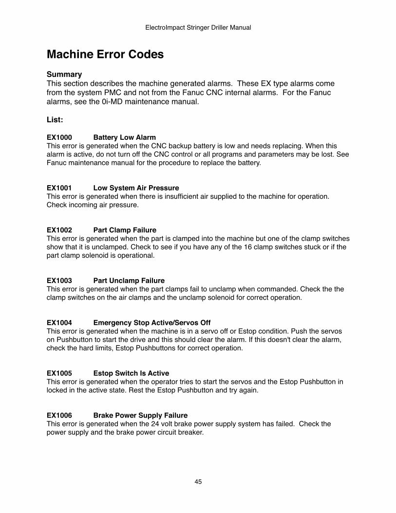
Machine Error CodesSummaryThis section describes the machine generated alarms. These EX type alarms come from the system PMC and not from the Fanuc CNC internal alarms. For the Fanuc alarms, see the 0i-MD maintenance manual.
List:
EX1000! Battery Low AlarmThis error is generated when the CNC backup battery is low and needs replacing. When this alarm is active, do not turn off the CNC control or all programs and parameters may be lost. See Fanuc maintenance manual for the procedure to replace the battery.
EX1001! Low System Air PressureThis error is generated when there is insufficient air supplied to the machine for operation. Check incoming air pressure.
EX1002! Part Clamp FailureThis error is generated when the part is clamped into the machine but one of the clamp switches show that it is unclamped. Check to see if you have any of the 16 clamp switches stuck or if the part clamp solenoid is operational.
EX1003! Part Unclamp FailureThis error is generated when the part clamps fail to unclamp when commanded. Check the the clamp switches on the air clamps and the unclamp solenoid for correct operation.
EX1004! Emergency Stop Active/Servos OffThis error is generated when the machine is in a servo off or Estop condition. Push the servos on Pushbutton to start the drive and this should clear the alarm. If this doesn't clear the alarm, check the hard limits, Estop Pushbuttons for correct operation.
EX1005! Estop Switch Is ActiveThis error is generated when the operator tries to start the servos and the Estop Pushbutton in locked in the active state. Rest the Estop Pushbutton and try again.
EX1006! Brake Power Supply FailureThis error is generated when the 24 volt brake power supply system has failed. Check the power supply and the brake power circuit breaker.
ElectroImpact Stringer Driller Manual
45
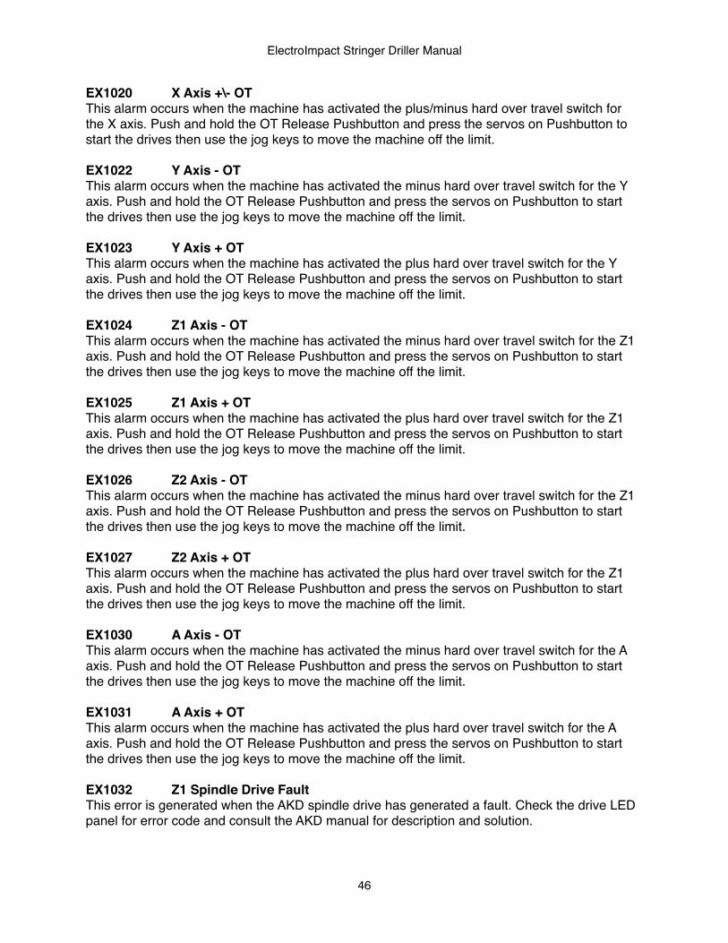
EX1020! X Axis +\- OTThis alarm occurs when the machine has activated the plus/minus hard over travel switch for the X axis. Push and hold the OT Release Pushbutton and press the servos on Pushbutton to start the drives then use the jog keys to move the machine off the limit.
EX1022! Y Axis - OTThis alarm occurs when the machine has activated the minus hard over travel switch for the Y axis. Push and hold the OT Release Pushbutton and press the servos on Pushbutton to start the drives then use the jog keys to move the machine off the limit.
EX1023! Y Axis + OTThis alarm occurs when the machine has activated the plus hard over travel switch for the Y axis. Push and hold the OT Release Pushbutton and press the servos on Pushbutton to start the drives then use the jog keys to move the machine off the limit.
EX1024! Z1 Axis - OTThis alarm occurs when the machine has activated the minus hard over travel switch for the Z1 axis. Push and hold the OT Release Pushbutton and press the servos on Pushbutton to start the drives then use the jog keys to move the machine off the limit.
EX1025! Z1 Axis + OTThis alarm occurs when the machine has activated the plus hard over travel switch for the Z1 axis. Push and hold the OT Release Pushbutton and press the servos on Pushbutton to start the drives then use the jog keys to move the machine off the limit.
EX1026! Z2 Axis - OTThis alarm occurs when the machine has activated the minus hard over travel switch for the Z1 axis. Push and hold the OT Release Pushbutton and press the servos on Pushbutton to start the drives then use the jog keys to move the machine off the limit.
EX1027! Z2 Axis + OTThis alarm occurs when the machine has activated the plus hard over travel switch for the Z1 axis. Push and hold the OT Release Pushbutton and press the servos on Pushbutton to start the drives then use the jog keys to move the machine off the limit.
EX1030! A Axis - OTThis alarm occurs when the machine has activated the minus hard over travel switch for the A axis. Push and hold the OT Release Pushbutton and press the servos on Pushbutton to start the drives then use the jog keys to move the machine off the limit.
EX1031! A Axis + OTThis alarm occurs when the machine has activated the plus hard over travel switch for the A axis. Push and hold the OT Release Pushbutton and press the servos on Pushbutton to start the drives then use the jog keys to move the machine off the limit.
EX1032! Z1 Spindle Drive FaultThis error is generated when the AKD spindle drive has generated a fault. Check the drive LED panel for error code and consult the AKD manual for description and solution.
ElectroImpact Stringer Driller Manual
46

EX1033! Z2 Spindle Drive FaultThis error is generated when the AKD spindle drive has generated a fault. Check the drive LED panel for error code and consult the AKD manual for description and solution.
ElectroImpact Stringer Driller Manual
47