safety precautions - chinnick theatre services · phonic understands the importance of sound...
TRANSCRIPT


PHONIC CORPORATIONPAA2 USER’ S MANUALPage 2
SAFETY PRECAUTIONS
Improper operation and handling of this unit may lead to malfunction. Please read
the following precautions before operating.
1. To prevent damage, avoid operating PAA2 under these conditions:A Temperatures below 0 degrees C (32 F) or above 40 degrees C (104 F)
B Strong magnetic waves in nearby areas
C Static electricity
D High humidity
E Sudden temperature changes
F Large amount of dust in area of operation
2. Avoid placing heavy objects on top of PAA2.
3. DO NOT tear apart PAA2.
4. Never insert foreign objects into measurement microphone, connectors,or other openings.
5. If PAA2 is damaged in any way, immediately turn off the power andcontact your reseller. DO NOT continue using the unit.
6. Avoid spilling any liquid on or into PAA2. If spilling or dampening occurs,turn power off immediately and contact your reseller. DO NOT continueusing the unit.
WARNING! Always use AA SIZE 1.5V DC alkaline battery or 6 volt DCwith 500mA AC power adaptor to power PAA2. Use of an improperpower supply will void the manufacturer product warranty. To ensure theaccuracy of all measurements please use only the included AC power
adaptor.
SAFETY PRECAUTIONS

PAA2 USER’ S MANUAL Page 3PHONIC CORPORATION
Introduction.......................................................4
Features...........................................................5
Meau map.........................................................6
Inside the gift box..............................................7
Meet your new best friend PAA2...........................8
Getting Started.................................................12
Operation Tips..................................................13
RTA (Real Time Analyzer)...................................14
SPL (Sound Pressure Level)...............................16
EQ SETTING....................................................17
Line Voltage Measurement..................................18
Memory...........................................................20
Setting.............................................................22
Phase Check....................................................26
Generator.........................................................28
Power Off.......................................................28
Simultaneous Operation With PC........................29
Dimensions......................................................33
Specifications....................................................34
Appendix: List of 26 Audio Testing Signals...............36
PHONIC reserves the right to improve or alter any information supplied within this document
without prior notice. V1.2 July 01, 2003
CONTENTS

PHONIC CORPORATIONPAA2 USER’ S MANUALPage 4
INTRODUCTION
Thank you for purchasing PAA2, Personal Audio Assistant! PAA2 is a highly accurate
audio analyzer that nestles in the palm of your hand, giving you all the tools you
need to set up any sound system. With 31-band real-time spectrum analysis, SPL
and dBu/dBV/line voltage measurement, EQ setting and phase checking, PAA2 is
every sound engineer’ s best partner. This personal audio assistant is battery powered
(4 AA size) to allow for ultimate portability while ensuring the maximum level of
accuracy.
With PAA2, you will conquer all acoustic environments with precision and ease.
PHONIC understands the importance of sound reproduction management. We know
that as a professional, your main concern is sound quality. Consequently, with an
audio tool like PAA2, you are given a precise ruler to obtain proper measurements
and to guarantee the best possible quality of sound that every professional sound
engineers dreams of. PAA2 is therefore an extremely accurate and effective means
for you to gather all the useful data to sharpen your decision in making necessary
adjustments to any system setup.
PHONIC also realizes that you need a useful audio tool that is easy and convenient
to operate . PAA2 is designed with that concept in mind. Its functions can easily be
accessed through its jog control and function buttons in the front. So, turn on your
new audio assistant; and let the adventure begin. We are confident you will find that
PAA2 really pays off.
To help you get familiar with your PAA2, this manual includes instructions on every
function listed in the main menu and sub-menus. Let this manual help you become
familiar with this handy device.
INTRODUCTION

PAA2 USER’ S MANUAL Page 5PHONIC CORPORATION
FEATURES
Personal Audio Assistant
Palm Size Audio Analyzer
31-band Real Time SpectrumAnalyzer
Built-in calibrated measurementmicrophone
Sound Pressure Level Meter from30dB~130dB
Line signal measurement displayin dBu, dBV, or Voltage
A, C weighting or flat
3 level range selection for dB SPLand line signal
Line signal measuring range:dBu = -50 ~ +40dBudBV= -52 ~ +38dBVVolts = 5mV ~ +80V
Maximum level display
Peak hold display
4 standard response times:35ms, 125ms (F), 250ms (M),1sec (S)
10 memories for measurementand 6 for average calculation
31-band EQ setting level display(boost/cut)
160 x 160 graphic display withback light and contrastadjustment
Phase checker
SPL meter Calibration throughsound levelcalibrator (eg: B & K Type 4231)
Noise generator with pink noise,1K Hz and polarity test signal,balanced output
Low power consumption for over4 hours continuous operation with4 AA size alkaline batteries(Adapter power supply operationavailable. When power is usedfrom adapter, it automaticallycuts off battery power)
3 power modes: (1) Power savingmode: Auto Off- when none ofthe buttons has been pressed for15 minutes (2) Manual Off (3)O f f
XLR input and output sockets
RS232 communication port, forsimultaneous operation throughlaptop or PC
One CD-ROM with audio testsignals and software for PC
FEATURES

PHONIC CORPORATIONPAA2 USER’ S MANUALPage 6
MENU MAP
Press the ENTER button or jog control to enter the main menu and sub menus:
MENU MAP
PAA2 USER’ S MANUAL Page 7PHONIC CORPORATION
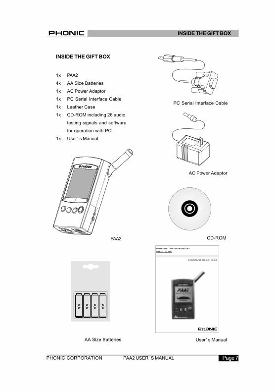
User’ s Manual
INSIDE THE GIFT BOX
1x PAA2
4x AA Size Batteries
1x AC Power Adaptor
1x PC Serial Interface Cable
1x Leather Case
1x CD-ROM including 26 audio
testing signals and software
for operation with PC
1x User’ s Manual
INSIDE THE GIFT BOX
AC Power Adaptor
PC Serial Interface Cable
PAA2
AA Size Batteries
CD-ROM

PHONIC CORPORATIONPAA2 USER’ S MANUALPage 8
MEET YOUR NEW BEST FRIEND
PAA2
PAA2 comes with the following features:
controls and connections:
1. LCD Display160x160 graphic LCD screen provides
clear and large display.
2. Power On buttonBefore turning on the power, please
make sure the POWER LOCK switch
in the back is set at the “ON “position.
Then press the Power On button for 2
seconds to turn on the power. After
the power is on, this button wil l
activate (or turn off) the backlight for
the LCD display.
3. Right / Down buttonPress this button to highlight a selection
below or to the right of the current
selection.
4. Left / Up buttonPress this button to highlight a selection
up or to the left of the current selection.
5. Enter buttonPress this button to move from Real
Time Spectrum Analyzer (RTA) display
to FUNCTION MENU. After moving
the cursor to a desired function in the
menu by the RIGHT/DOWN or LEFT/
UP buttons, press this button to
activate desired function.
MEET YOUR NEW BEST FRIEND PAA2

PAA2 USER’ S MANUAL Page 9PHONIC CORPORATION
6. Jog ControlJog control, on the left-hand side of
this unit, provides the main point of
access to the functions in PAA2. Scroll
up and down the main and sub-menus
with it, and press the jog control button
to get into the main menu or sub menu.
Scroll to highlight the desired function,
and press it to activate the function.
Alternately, the three function buttons
(the above-mentioned buttons 3~5)
may also be used to scroll, highlight
or activate a function.
7. 6V DC Power InputVia this input, the user may connect
the power adaptor to PAA2. When
adapter is plugged in, the battery
power will be replaced by the adaptor.
ATTENTION: Always use the
adapter included in this gift box to
ensure measurement accuracy and
to avoid damaging PAA2.
8. PC Serial Interface port3.5Ø mini jack allows the user to
connect PAA2 to PC with the D-SUB
9-PIN female connector via the PC
serial port for simultaneous operation
with PC. Please see SIMUTANEOUS
OPERATION with PC for more
information.
MEET YOUR NEW BEST FRIEND PAA2

PHONIC CORPORATIONPAA2 USER’ S MANUALPage 10
9. Line output XLR male socketThrough this XLR male connector, the
user can send out three built-in audio
test signals: pink noise,1k Hz tone,
and polarity signal. The output level is
balanced -10dBu under 6DV power
supply.
10. Line input XLR female socketThis port allows you to send balanced
Line-level input to PAA2 via an XLR
jack. This signal input allows you to
measure line-level in dBu, dBV or AC
voltage for balanced, unbalanced
signal, or to check the phase of the
input signal.
Do not send DC voltage via this
connector into PAA2, it will cause
permanent damage to the unit.
11. Contrast controlBy adjusting this control, the user can
obtain better resolution from LCD when
needed.
12. Power lockSet this switch to the “ON” position
before turning on PAA2. Set to the
“OFF” position to prevent accidental
powering of the PAA2 when the unit is
not in use. It is recommended to set
this switch off when you will not be
using PAA2 for a long time.
MEET YOUR NEW BEST FRIEND PAA2

PAA2 USER’ S MANUAL Page 11PHONIC CORPORATION
13. Measurement MicrophoneTurn this accurate built- in
Omni-directional mic to operation
position (stands 45 degrees) by
pressing the axis base. Always press
the axis base before relocating the
mic. Do not turn the mic without first
pressing the axis base. This may
damage the microphone and result in
malfunction.
14. Stand MountA stand mount is located on the back
for connection to a tripod or any other
stand that has a standard #6~20
connecting screw, often found on
camera tripods.
15. Battery HolderPAA2 needs four AA batteries for
operation. Alkaline batteries are
recommended for maximum
operation duration. Under normal
operation, PAA2 has over four hours
of continuous operation with use of
alkaline batteries.
MEET YOUR NEW BEST FRIEND PAA2

PHONIC CORPORATIONPAA2 USER’ S MANUALPage 12
GETTING STARTED
(1) Open the battery cover and insert
four AA batteries, or simply plug in
the 6-volt DC power adaptor to the
power input. When adapter is plugged
in, the battery power will be replaced
by the adaptor.
ATTENTION: Use only the
adapter included in this gift box to
ensure measurement accuracy and
to avoid damaging PAA2. When using
the adaptor, turn off the (battery) power
first to prevent the PAA2 from
restarting. Sudden unplugging of the
adaptor power may cause the system
to crash. You may restore PAA2 by
resetting the power lock.
(2) Position the mic for operation by
pressing the axis base of the built-in
mic. To measure sound pressure level
or acoustic power, turn the axis base
until the mic stands at 45 degrees.
(3) Set the POWER LOCK to the
“ON” position.
(4) Press the power on button in the
front for two seconds to turn on the
power.
(5) A startup screen will appear for
about 10 seconds, then the real time
spectrum analyzer with 31-band will
appear on the screen. Three types of
display are constantly shown at the
top of the screen In RTA mode: level
range, weighting type, and max level.
(6) If you need backlight for your
operation, simply press the power on
button; press again to turn the
backlight off.
(7) Use the ENTER, UP/RIGHT and
DOWN/LEFT buttons to read the level
of each 31-band frequency
individually and in real-time, or to
navigate through the main and
sub-menus. Press the ENTER button
to enter the main menu and use the
UP/RIGHT and DOWN/LEFT buttons
to select a function. Then press
ENTER again to activate the highlight
function or to enter into the
sub-menus. The user may also use
the jog control to activate all
functions.
GETTING STARTED

PAA2 USER’ S MANUAL Page 13PHONIC CORPORATION
1. All functions can be activated by
operating ENTER, LEFT/UP and
DOWN/RIGHT buttons, or by the jog
control. It is recommended to use these
three buttons when taking low SPL
measurements.
2. Pressing the ENTER button when
the ESC (Escape) is highlighted in most
of the function menus will allow you to
exit the main menu or sub-menus.
3. Press and hold the ENTER button
or jog control for 2 seconds in most of
the function menus to return to the
real time spectrum analyzer.
4. Press the jog control or ENTER
button for 2 seconds to jump to the
SPL / Line level meter (enlarged
readout) in RTA mode.
5. Always turn off the power by going
to the POWER menu. Select OFF if
you wish to save the measurement
data and function setting into the
memory of PAA2.
6. Always prepare extra batteries or
external 6V DC power to ensure the
accuracy of the measurement. It is
not recommended to continue using
PAA2 for any measurement when the
battery is low.
OPERATION TIPS
7. When the result is above the
level range, the measurement is
still accurate unless CLIPPING has
appeared in the LEVEL box during
the measurement. When clipping
shows, reset the level range.
8. Turn on backlight only when the
level range is set at 70~130 dB
SPL or -20~+40dBu. A noise will
occur when turning on the backlight
and it may affect the result of the
measurement in the lower range.
ATTENTION: When the
battery is low, a blinking battery
icon “BATTERY LOW” will appear
at the WEIGHT box and last for 3
minutes on the screen. Low quality
batteries may cause PAA2 to
shutdown without warning. An
enlarged, blinking battery icon will
appear in the center of the LCD
screen if the user restarts the
PAA2 with insufficient battery
power.
OPERATION TIPS:

PHONIC CORPORATIONPAA2 USER’ S MANUALPage 14
ACOUSTIC ANALYSIS
FUNCTIONSThe following section contains
information concerning acoustic
analysis, and illustrates how to use
PAA2 to measure SPL level.
RTA (Real Time Analyzer)
Analyze the audio received through the
built-in omni-directional mic by dividing
the audio spectrum into 31-band, 1/3
octaves, and displaying a bar graph
that shows the dB level of each band
of sound from 20Hz to 20KHz in four
different response times (35ms,
125ms, 250ms, and 1sec) and in three
weighting types (A weighting, C
weighting and Flat).
Procedures
1 Approximately 10 seconds
after turning on the power, the
real time analyzer, with active
31-band center frequency
graphic meter, will appear on
the LCD screen.
2 Go to the SPL/LINE menu and
select SPL. Then press
ENTER button for two
seconds to return to RTA
display.
3 Go to SETTING menu to set
up appropriate WEIGHTING
type, LEVEL RANGE,
RESPONSE TIME, or to set
the maximum or PEAK HOLD
display on (or off), Press
ENTER for two seconds to
return to RTA display.
4 Press ENTER to freeze
measurement data. Press
ENTER again on the
highlighted VALUE to view the
value of each center
frequency.
5 Use the LEFT/UP and RIGHT/
DOWN buttons or simply
scroll the JOG control to view
the level of dB SPL in
RTA (Real Time Analyzer)

PAA2 USER’ S MANUAL Page 15PHONIC CORPORATION
real-t ime for the center
frequency of all 31 bands.
The default readout is the ALL
FREQUENCY level.
Beneath you will find two readouts: the
numbers in the left column display
the frequency while the numbers in
the right column display the frequency
levels.
The graphic shown indicates that the
user has set the level range at 50~110
SPL, A weighting. The max level during
the time of measurement is 105.5 dB ,
The user is reading at 1K Hz, which has
a dB SPL of 102.8.
If you would l ike to store the
measurement data in the memory of
PAA2, go to the STORE menu. This
feature is only available when
measuring the SPL. ( The user can also
save the measured spectrum data into
one of the ten memories. Please refer
to MEMORY/STORE for more
information.)
RTA (Real Time Analyzer)
PHONIC CORPORATIONPAA2 USER’ S MANUALPage 16
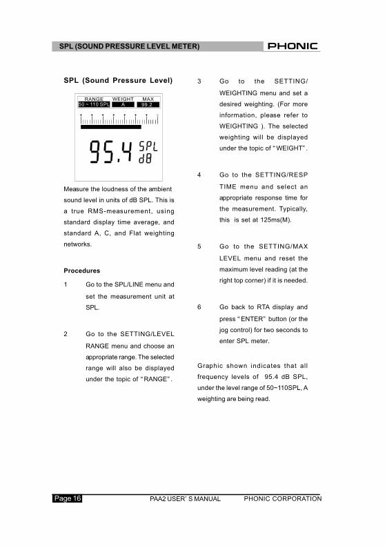
SPL (Sound Pressure Level)
Measure the loudness of the ambient
sound level in units of dB SPL. This is
a true RMS-measurement, using
standard display time average, and
standard A, C, and Flat weighting
networks.
Procedures
1 Go to the SPL/LINE menu and
set the measurement unit at
SPL.
2 Go to the SETTING/LEVEL
RANGE menu and choose an
appropriate range. The selected
range will also be displayed
under the topic of “RANGE” .
3 Go to the SETTING/
WEIGHTING menu and set a
desired weighting. (For more
information, please refer to
WEIGHTING ). The selected
weighting will be displayed
under the topic of “WEIGHT” .
4 Go to the SETTING/RESP
TIME menu and select an
appropriate response time for
the measurement. Typically,
this is set at 125ms(M).
5 Go to the SETTING/MAX
LEVEL menu and reset the
maximum level reading (at the
right top corner) if it is needed.
6 Go back to RTA display and
press “ENTER” button (or the
jog control) for two seconds to
enter SPL meter.
Graphic shown indicates that all
frequency levels of 95.4 dB SPL,
under the level range of 50~110SPL, A
weighting are being read.
SPL (SOUND PRESSURE LEVEL METER)
RANGE50 ~ 110 SPL
WEIGHT MAXA 99.2
PAA2 USER’ S MANUAL Page 17PHONIC CORPORATION
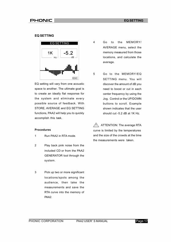
EQ SETTING
EQ setting will vary from one acoustic
space to another. The ultimate goal is
to create an ideally flat response for
the system and eliminate every
possible source of feedback. With
STORE, AVERAGE and EQ SETTING
functions, PAA2 will help you to quickly
accomplish this task.
Procedures
1 Run PAA2 in RTA mode.
2 Play back pink noise from the
included CD or from the PAA2
GENERATOR tool through the
system.
3 Pick up two or more significant
locations/spots among the
audience, then take the
measurements and save the
RTA curve into the memory of
PAA2.
4 Go to the MEMORY/
AVERAGE menu, select the
memory measured from those
locations, and calculate the
average.
5 Go to the MEMORY/EQ
SETTING menu. You wil l
discover the amount of dB you
need to boost or cut in each
center frequency by using the
Jog. Control or the UP/DOWN
buttons to scroll. Example
shown indicates that the user
should cut -5.2 dB at 1K Hz.
ATTENTION: The average RTA
curve is limited by the temperatures
and the size of the crowds at the time
the measurements were taken.
EQ SETTING

PHONIC CORPORATIONPAA2 USER’ S MANUALPage 18
LINE VOLTAGE MEASUREMENT
Measure the line voltage level in units
of dBu, dBV, and voltage, using
standard response time, and standard
A, C, and flat weighting network (Under
normal conditions, please set it at Flat).
PAA2 can only measure AC voltage.
Using PAA2 to meaure DC voltage may
damage PAA2 and wil l void the
warranty.
Procedures
1 Go to the SPL/LINE menu and
set the measurement unit at
dBu, dBV, or voltage.
2 Go to the SETTING/LEVEL
RANGE menu and choose an
appropriate range. The selected
range will also appear under
the topic of “RANGE” .
3 Go to the SETTING/
WEIGHTING menu and set a
desired weighting. (For more
information, please refer to
WEIGHTING ). The selected
range will also appear under the
topic of “WEIGHT” . “ FLAT”
is typically used to measure
line voltage.
4 Go to the SETTING/RESP
TIME menu and select an
appropriate response time for
the measurement.
5 Go to the SETTING/MAX
LEVEL menu and reset the
maximum level reading (at the
right top corner) if it is needed.
6 Go back to RTA display. Here
you can read the level of any
or all frequencies. If al l
frequency readouts are
needed, press “ ENTER”
button (or the jog control) for
two seconds to enter l ine
voltage level meter.
LINE VOLTAGE MEASUREMENT

PAA2 USER’ S MANUAL Page 19PHONIC CORPORATION
ATTENTION:
1. If the level is lower than 127mV
when measuring voltage, PAA2 will
show it in mV. If the level is higher
than 127mV, the data will be shown in
voltage . For example, 120mV will read
as 120.0mV, and 200mV will be shown
as 0.2V.
2. The measurement for line voltage
cannot be saved into the memory of
PAA2.
LINE VOLTAGE MEASUREMENT

PHONIC CORPORATIONPAA2 USER’ S MANUALPage 20
MEMORYThe sub-menus of MEMORY include:
STORE, RECALL, AVERAGE, EQ
SETTING.
STORE
The user can save up to 10 sets of
measured data, as well as 6 averaged
sets, into the memory of PAA2 for
further analysis or uploading.
Procedures (after RTA measurement
is complete)
1 Go to the MEMORY menu and
select STORE.
2 Select a number from 1~10, and
press YES.
3 When cursor automatically
moves to ESC, PAA2 has
finished saving the data and
previously saved data will be
over-written.
ATTENTION: This function is
only available when in RTA mode.
RECALL
The user can recall all data saved in
the memory of PAA2 to make
comparisons or to see the differences
between the measurements.
Procedures
1 Go to the MEMORY menu and
select RECALL.
2 Select the already-saved data
from 1~10 or A~F, and press
YES.
3 Each value will be displayed
under VALUE in a 31-band
center frequency value and
an all frequency value.
4 When you see a flashing ESC
in the Hz column, press
ENTER to return to the
MEMORY menu.
MEMORY
SETTING
CABLE TESTCABLE TEST
STORE
RECALL
AVERAGE 102
5
6
A 31 100 315 1K 10K3.15K
POWER OFFPOWER OFFESCESC
ESC3
4
7
8
1 YES
NO
9
MEMORY
VALUE
SPL / LINESPL / LINE
MEMORY
SETTING
RECALL
STORE
2
3
4
5
6
7
8
9
10
A
B
C
D
E
F
1
MEMORY
A 31 100 315 1K 10K3.15K
MEMORY

PAA2 USER’ S MANUAL Page 21PHONIC CORPORATION
AVERAGE
The user can choose from memory
1~10 to compute average calculations,
which are essential for EQ setting.
Procedures
1 Go to the MEMORY menu and
select AVERAGE.
2 Select any combination of data
from memory 1~10 by moving
the cursor to that number and
pressing the ENTER button, or
simply choose ALL if you want
to do the average calculation
for al l ten saved
measurements . If you want to
undo the selection, move the
cursor to the selected number
and press ENTER again.
3 The selected number(s) will
appear with a square around it
(them) for identification.
4 Press AVG when all selections
have been made. A list of
selected measurements will
be shown for confirmation.
5 Press RUN and PAA2 will
automatically calculate the
average, or press ESC to
cancel.
6 After you run the average
calculation, COMPLETE will
appear on the screen. The
user may then select results
from A-F and press YES to
save selected average
calculations to PAA2 .
Previously saved data will be
over-written. Saving new
results wil l over-write
previously saved data. PAA2
will automatically go to EQ
SETTING menu as soon as
calculations are complete.
Example shown means the
user has selected memory 1,
3 and 6 for average
calculation.
ATTENTION: I t is not
recommended to calculate average
of saved data with different weighting
settings. PAA2 will ignore the peak
value when calculating the average,
even if the peak value was activated.
A 31 100 315 1K 10K3.15K
SPL / LINESPL / LINE
MEMORY
SETTING
RECALL
SETTING
CABLE TESTCABLE TEST
EQ SETTINGEQ SETTING
POWER OFFPOWER OFFESCESCSTORE
RECALL
AVERAGE
EQ SETTINGEQ SETTINGEQ SETTINGEQ SETTING
AVERAGE
ALL
2
3
4
5 9
6 10
7
8
1
ESC
AVG
MEMORY
MEMORY

PHONIC CORPORATIONPAA2 USER’ S MANUALPage 22
SETTINGThe sub-menus of SETTING include
WEIGHTING, LEVEL RANGE, MAX
LEVEL, PEAK HOLD, RESPONSE
TIME, and CALIBRATION.
WEIGHTING
A sound level meter must be designed
so that it hears the sound level in the
same way as humans.
Generally, the sensitivity of human
hearing is restricted to the frequency
range of 20Hz to 20KHz. The human
ear, however, is most sensitive to
sound in the range of 500Hz to 8,000Hz.
The ear becomes progressively less
sensitive to sound above or below this
range. To account for this characteristic
of human hearing, sound pressure level
meters incorporate a f i l tering of
acoustic signals according to
frequency. This filtering (weighting
type) is devised to correspond to the
varying sensitivity of the human ear
to sound over the audible frequency
range. PAA2 comes with both A-
weighting and C-weighting standardized
by the ANSI, American National
Standards Institute. A-weighting is
the most frequently used weighting
type and is used for measuring lower
sound levels, while C-weighting is used
for higher sound levels.
The user can set the weighting for
measurements in dBu, dBV or voltage.
Procedures
1 Go to the SETTING/
WEIGHTING menu.
2 Select an appropriate weighting
for the measurement and press
YES.
3 Press ESC to return.
WEIGHTING
FLAT
A
C
SETTING
ESC
A 31 100 315 1K 10K3.15K
SETTING

PAA2 USER’ S MANUAL Page 23PHONIC CORPORATION
LEVEL RANGE
PAA2 has three different ranges for
measurements in SPL, dBu, dBV and
voltage.
SPL : 30~90, 50~110, 70~130
dBu : -50~+10, -35~+25, -20~+40
dBV: -52~+8, -37~+23, -22~+38
Voltage: 5m~2.45V, 14m~14V
77.5m~80V
Procedures
1 Go to the SETTING/LEVEL
RANGE menu.
2 Select an appropriate range for
the measurement and press
ENTER button.
3 Press ESC to return.
MAX LEVEL
Maximum level will constantly be
shown and measured on the LCD
screen. The user should reset the
max level before each new
measurement.
Procedures
1 Go to the SETTING/MAX
LEVEL menu.
2 Highlight RESET and press
ENTER button to reset the
max level measurement. The
menu will automatically return
to the SETTING sub-menu.
Press ESC to return if it you
do not want to reset.
3 A new max level display will
be shown in the MAX column
three seconds after returning
to the RTA operation.
LEVEL RANGE
70 ~ 130 dBSPL
30 ~ 90 dBSPL
SETTING
50 ~ 110 dBSPL
ESC
A 31 100 315 1K 10K3.15K
MAX LEVEL
RESET
SETTING
ESC
A 31 100 315 1K 10K3.15K
SETTING

PHONIC CORPORATIONPAA2 USER’ S MANUALPage 24
RESPONSE TIME
Response time settings wil l vary
according to the user’ s measurement
goals.
35 ms: Extremely Fast (for
explosive sound)
125 ms(F): Fast
250 ms(M): Middle
1 sec(S): Slow
Procedures
1 Go to the SETTING/RESP TIME
menu, select an appropriate
response time and press
ENTER button.
2 Or press ESC to return.
PEAK HOLD
Peak hold allows the user in RTA mode
to constantly display the peak values
of all measured frequencies,
individually or collectively.
Procedures
1 Go to the SETTING/PEAK
HOLD menu.
2 Highlight ON to activate peak
hold display.
3 Highlight OFF to cancel peak
hold display.
4 Press ESC to return.
ATTENTION: When saving the
memory with “PEAK HOLD” on, the
peak level will only be displayed when
the user recalls that memory when the
“PEAK HOLD” setting is on. By setting
the PEAK HOLD off, the user may
then view the levels from all
frequencies, individually or collectively.
PEAK HOLD
ON
OFF
SETTING
ESC
A 31 100 315 1K 10K3.15K
RESP TIME
35 ms
125 ms (F)
250 ms250 ms250 ms (M)
c (S)c (S)1 se
SETTING
ESC
A 31 100 315 1K 10K3.15K
SETTING

PAA2 USER’ S MANUAL Page 25PHONIC CORPORATION
CALIBRATION
Under normal operation, you may
never need to calibrate your PAA2.
Only calibrate PAA2 if measurement
data or operation of the unit is abnormal.
Anyone can calibrate PAA2 and regain
accurate sound pressure level
measurement by using a sound level
calibrator with 1/2" diameter adapter that
sends out 1K Hz tone. The user can
use a B&K TYPE 4231 sound level
calibrator to calibrate.
Procedures
1 Go to SETTING/PEAK HOLD
and set it to OFF.
2 Go to SETTING/RESP TIME
and set it at 250ms(M).
3 Place a sound level calibrator
with a microphone connector of
1/2" diameter close to the
microphone of PAA2.
4 Go to the SETTING/
CALIBRATION menu and
activate the function.
5 Adjust the level measured from
the SPL calibrator by pressing
UP/DOWN buttons until the
level reaches that of the sound
level calibrator. Pressing the
UP button each time wil l
increase the value by 0.1dB;
pressing the DOWN button
each time will decrease by 0.1
dB. The user will need to
adjusting until the readout of
the PAA2 is identical with the
one of the standard SPL
calibrator.
6 Press the ENTER button to
complete the calibration and
to return to RTA display.
ATTENTION:
(1) Under normal operation, you
may never need to calibrate your
PAA2.
(2) If you want to cancel the
calibration function, press the ENTER
button to exit before making any
adjustment.
(3) If you want to restore the
default setting, simply use the UP/
DOWN buttons to adjust the OFFSET
value untill it reads 0.0 dB, and then
press the ENTER button to complete
setting.
SETTING

PHONIC CORPORATIONPAA2 USER’ S MANUALPage 26
PHASE CHECK Measure the phase of an electrical
signal or speaker wiring in order to find
out if the signal phase or the speaker
wiring is correct. Polarity signal is
usually needed for checking the
speaker wiring.
Procedures
For electrical signal
1 Go to the SPL/LINE and select
dBu.
2 Go to the SETTING/LEVEL
RANGE menu and select an
appropriate range for phase
checking.
3 Send the electrical signal to the
female XLR input jack.
4 A big “ +” means the signal is
in phase.
5 A big “ -” means the signal is
out of phase.
6 A big “?” means that the signal
level is lower than the current
level range sett ing of the
PAA2, and it therefore cannot
be detected by PAA2.
PHASE CHECK

PAA2 USER’ S MANUAL Page 27PHONIC CORPORATION
For speaker wiring
1 Go to the SETTING/LEVEL
RANGE menu and select the
high (70~130dB) range for
phase checking. (The low range
30~90dB is not recommended
for phase checking because
the environment noise will
affect the result.)
2 Go to the GENERATOR menu
and select POLARITY (or play
the included CD to send out
the polarity signal through that
speaker).
3 Stand one meter in front of the
speaker that plays out the
polarity signal, go to the
PHASE CHECK menu and
activate.
4 A big “ +” means the speaker
is in phase, and the wiring is
correct.
5 A big “ -” means the speaker
is out of phase, and the wiring
of the speaker is incorrect.
6 A big “ ?” or a screen
switching between “ +” and
“ -” means the sound pressure
level is not detectable .
ATTENTION: Make sure the
sound pressure level of the polarity
signal from the system is louder than
the environment noise, otherwise
PAA2 will not be able to detect the
phase of the speaker.
PHASE CHECK

PHONIC CORPORATIONPAA2 USER’ S MANUALPage 28
GENERATOR
PAA2 can send out pink noise, polarity
signal, and 1K Hz tone, via the XLR
Male connector, to an external system
at -10 dBu(balanced).
Pink noise: mostly used for acoustic
environment adjusting. For
example: sound system
equalization.
Polarity: often used to check the
phase of a signal or
speaker wiring.
1K Hz tone:widely used among
professionals for audio
signal testing.
Procedures
1 Connect PAA2 to your system
via the XLR-male connector.
2 Go to the GENERATOR menu
and highlight one of the signals
to activate it.
3 Press ESC to return or press
OFF to cancel.
POWER OFF
There are three kinds of settings to
turn off PAA2.
Procedures
1 Go to the POWER menu.
2 Select AUTO OFF. PAA2 will
automatically shut down and
turn off its power 15 minutes
after the last operation.
3 Select MANUAL OFF. PAA2
will not automatically shut
down, unless batteries are
dead.
4 Select OFF. PAA2 wil l
immediately shut down and
turn off i ts power. It is
necessary for the user to turn
off the power this way if they
wish to save the measurement
data into the memory of PAA2.
POLARITY
PINK NOISE
1K Hz
ESC
OFF
GENERATOR
A 31 100 315 1K 10K3.15K
POWER
ESC
AUTO OFF
OFF
MANUAL OFF
A 31 100 315 1K 10K3.15K
GENERATOR /POWER OFF

PAA2 USER’ S MANUAL Page 29PHONIC CORPORATION
SIMULTANEOUS OPERATION
WITH PC
Simultaneous operation with a PC
allows for remote control operation in
spaces that do not require the presence
of an individual to take measurements.
By connecting PAA2 to the PC, the
user may also save and print data.
The software, supported by Windows
98 and above, can be found in the
included CD, which also contains 26
testing signals.
ATTENTION: When engaging
simultaneous operation with PC, only
the mouse and its keys are functional
It is recommended that the user power
PAA2 through the power adapter instead
of a battery. PAA2 should also be
positioned properly before engaging
remote control.
Procedures for installation and
simultaneous operation:
1 Turn on the PC and insert the
CD.
2 Find setup.exe, double click
to begin installation and follow
the instructions.
3 Go to start menu and select
PAA2 ON LINE. The window
of PAA2 ON LINE SOFTWARE
will appear on the screen.
4 Connect PAA2 to PC via
RS232 cable through the serial
port and turn on PAA2.
5 Go to FILE, select ON LINE
to activate simultaneous
operation. If you cannot
execute ON LINE, please go
to OPTION/PORT, select a
COM number and run TEST.
The software wil l then
automatically detect the
current serial port connecting
to PAA2 and save the setting.
The data previously saved in
PAA2 will immediately be
uploaded and the icon at the
bottom right corner will switch
from Off Line to On Line. If
no data is saved in the
memory of PAA2, it will show
a primitive level of 85dB for
all, frequencies in FLAT with a
level range of 30~90 dB SPL.
SIMULTANEOUS OPERATION WITH PC

PHONIC CORPORATIONPAA2 USER’ S MANUALPage 30
6 As soon as uploading is
finished, you may begin to
operate PAA2 by moving the
cursor of the mouse, clicking
the MENU on the PC screen to
enter into the menu and
sub-menus.
7 Now that PAA2 is operating
simultaneously with the PC, the
function being activated will
show on both PAA2 and on PC.
8 Go to FILE and click on OFF
LINE if you need to disable ON
LINE operation.
Once the procedures are finished , you
should be able to proceed with the
following functions:
1 Go to FILE, select Print, and a
printer selection window will
appear.
2 Select a printer from the list.
3 Select all data, or one of the 16
memories.
4 Select the quality level (Draft,
Low quality, Medium quality, or
High quality).
5 Click on Print, and the printer
window will disappear as soon
as the transmission is complete.
ATTENTIONS: Along with the
31-band value of the selected memory
and the EQ SETTING value, the name
of the file, date of printing, LEVEL
RANGE, WEIGHTING, and maximum
level will also be printed on the data
sheet.
SAVE FILE
1 Go to FILE, select Save File.
2 Select a desired directory or a
new destination, and give a
name to that file.
SIMULTANEOUS OPERATION WITH PC

PAA2 USER’ S MANUAL Page 31PHONIC CORPORATION
3 Clip on SAVE to save the file,
and all 16 memories will be
saved under that one file name
LEQ
LEQ is designed to measure sound
pressure level and automatically
calculate an average in one fixed
interval over a period of time in any
live event, therefore, it can only be
activated during on line.
1 Go to OPTION / LEQ to activate
this function.
2 Go to SEC menu to select an
interval. You can enter 180
hours and 59 minutes at most,
or any number between 0.001
and 59 for second)
3 Clip on the “eraser(CLEAR)”
to clear the measurement data
4 Clip on (START) to start
measuring
5 Clip on (STOP) to stop
measuring
6 Clip on the double disks icon
to save the result to one of the
six average memory (A~F)
ATTENTIONS: LEQ can only be
activated when the PEAK HOLD in
your PAA2 is set to OFF. When using
LEQ, user will not be able to operate
PAA2 and PAA2 ON LINE at the
same time.
(BACK) LIGHT
Clip on LIGHT to activate the back
light for PAA2, clip again to turn it off.
PEAK HOLD
1 Clip on ON to view the peak
value of each frequency and
all frequency. The level can
be found either from the bar
meter or in the memory chart.
2 Clip on OFF to view the RTA
value of each frequency and
all frequency
MEMORY (from the memory chart)
Clip on one of the memory number
(1~10 or A~F, the number of selected
memory would be marked) in the
memory chart to view the level in
each frequency and all frequency.
User can clip on the bar-meter in the
spectrum to see a specific frequency
SIMULTANEOUS OPERATION WITH PC

PHONIC CORPORATIONPAA2 USER’ S MANUALPage 32
for readout or view them in the RTA
Value column.
ATTENTIONS: The user may
rename every memory by double
clicking the number of the memory in
the memory chart. The following
functions, along with PORT, are not
accessible during on-line.
The following functions, along with
PORT, are not accessible during on line.
OPEN FILE
1 Go to FILE, select Open File.
2 Locate the file previously saved
in your PC and double click it.
3 The data is now available for
further operation.
MEMORY (from the menu)
AVERAGE
1 Go to MEMORY / AVERAGE
and activate average function.
2 Choose by clicking memory
1~10 for average calculation.
The original setting of each
memory level range will display
next to its number.
3 Click on AVG to run thecalculation.
SIMULTANEOUS OPERATION WITH PC
4 Select a memory from A~F, and
click on Save to save the result
(previousy saved data wil l be
over-written), or click on Cancel to
exit. The user can view the result
(either in graphic or in text)
immediately in either the result box
or in the memory chart. Level range
will be displayed at the top.
EQ SETTING
1 Select a memory (1~10 or A~F to
adjust the EQ.
2 Go to MEMORY and activate EQ
setting function.
3 Move the cursor and click on each
bar meter to find out how much dB
you need to cut or boost for each
center frequency.
CLEAR
1 Go to MEMORY / CLEAR.
2 Select one memory, 1~10 or A~F,
from the sub-menu, and the
memory will be deleted immediately.
Select “All” if you need to delete
all the memories that are presently
loaded into PC.

PAA2 USER’ S MANUAL Page 33PHONIC CORPORATION
144.9
5/5
.70
82.95/3.26
39.42/1.55
DIMENSIONS
DIMENSIONS

PHONIC CORPORATIONPAA2 USER’ S MANUALPage 34
PAA2
Input/Output:
MicrophoneBuilt-in miniature omni direction
condenser microphone
Line XLR jacks for line input and output
Data Port 3.5mm mini stereo phone jack for RS232
Display :160X160 LCD screen with contrast
adjustment and back light
SPL, dBu, dBV, Voltage Barograph and digit display
RTA
31-band, 0.5dB resolution
Center frequencies ISO standard
from 20Hz to 20KHz
Measurement Range:
SPL (Microphone input) 30 to 130 dB SPL
dBu (Line input) -50 to +40 dBu
dBV (Line Input) -52 to +38 dBV
Volatge (Line Input) 5 mV to 80 V
Setting
Weighting A, C or Flat
Peak hold ON/OFF
Maximum level display RESET
Response time 35 ms, 125 ms, 250 ms, 1 sec
SPECIFICATIONS
PAA2 USER’ S MANUAL Page 35PHONIC CORPORATION
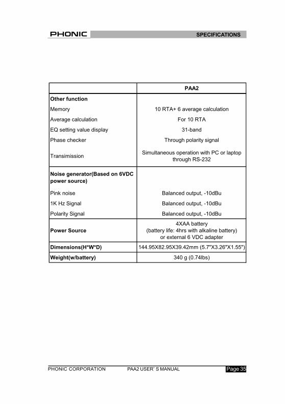
PAA2
Other function
Memory 10 RTA+ 6 average calculation
Average calculation For 10 RTA
EQ setting value display 31-band
Phase checker Through polarity signal
TransimissionSimultaneous operation with PC or laptop
through RS-232
Noise generator(Based on 6VDC
power source)
Pink noise Balanced output, -10dBu
1K Hz Signal Balanced output, -10dBu
Polarity Signal Balanced output, -10dBu
Power Source
4XAA battery
(battery life: 4hrs with alkaline battery)
or external 6 VDC adapter
Dimensions(H*W*D) 144.95X82.95X39.42mm (5.7"X3.26"X1.55")
Weight(w/battery) 340 g (0.74lbs)
SPECIFICATIONS

PHONIC CORPORATIONPAA2 USER’ S MANUALPage 36
26 AUDIO TEST SIGNALS
The following is the list of the audio test
signals on the CD included in the PAA2 gift
box:
1. Pink noise -10 dBFS, 60 seconds
2. Polarity testing signal
3. White noise -10 dBFS, 60 seconds
4. 250Hz sine signal -10 dBFS, 30
seconds
5. 500Hz sine signal -10 dBFS, 30
seconds
6. 1KHz sine signal -10 dBFS, 30
seconds
7. 2KHz sine signal -10 dBFS, 30
seconds
8. 5KHz sine signal -10 dBFS, 30
seconds
9. 10KHz sine signal -10 dBFS, 30
seconds
10. 12.5KHz sine signal -10 dBFS, 30
seconds
11. Sweep frequency up 20Hz~20KHz,
-10 dBFS, 5 seconds for each
frequency: 20Hz, 25Hz, 31.5Hz,
40Hz, 50Hz, 63Hz, 80Hz, 100Hz,
125Hz, 160Hz, 200Hz, 250Hz,
315Hz, 400Hz, 500Hz, 630Hz,
800Hz, 1KHz, 1.25KHz, 1.6KHz,
2KHz, 2.5KHz, 3.15KHz, 4KHz,
5KHz, 6.3KHz, 8KHz, 10KHz,
12.5KHz, 16KHz, 20KHz
12. Channel test -10 dBFS, at 1KHz,
left channel
13. Channel test -10 dBFS, at 1KHz,
right channel
14. Sweep frequency up 20Hz~20KHz,
-20 dBFS, 5 seconds for each
frequency
15. In phase, 0 dBFS, at 250Hz, 30
seconds
16. Out of phase, 0 dBFS, at 250Hz,
30 seconds
17. Digital blank, 60 seconds
18. SMPTE/EBU, time code, 30
seconds
19. High E
20. Low B
21. Low G
22. Low D
23. Low A
24. Low E
25. Frequency sweep up,
20Hz~20KHz, 0 dBFS
26. Frequency sweep down,
20KHz~20Hz, 0 dBFS
APPENDIX


Information in this document is subject to change without notice.