safety relay modules srb seriesk3 k2 k5 k4 k1. guard closed k3 k2 k1 opened enabling output k1 k2 k3...
TRANSCRIPT

Safety Relay Modules
SRB series
2
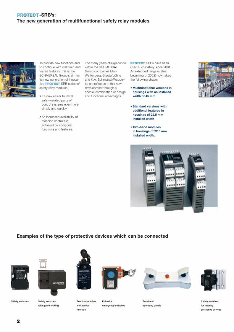
Examples of the type of protective devices which can be connected
To provide new functions andto continue with well tried andtested features: this is theSCHMERSAL Group’s aim forits new generation of innova-tive SRB series ofsafety relay modules.
• It’s now easier to installsafety-related parts of control systems even moresimply and quickly.
• An increased availability ofmachine controls isachieved by additional functions and features.
The many years of experiencewithin the SCHMERSALGroup companies Elan/Wettenberg, Steute/Löhneand K.A. Schmersal/Wupper-tal are reflected in this newdevelopment through a special combination of designand functional advantages.
SRBs have beenused successfully since 2001.An extended range (status:beginning of 2002) now takesthe following shape:
• Multifunctional versions inhousings with an installedwidth of 45 mm
• Standard versions withadditional features inhousings of 22.5 mm installed width
• Two-hand modules in housings of 22.5 mm installed width.
-SRB’s: The new generation of multifunctional safety relay modules
Safety switches
for rotating
protective devices
Pull-wire
emergency switches
Position switches
with safety
function
Safety switches
with guard locking
Safety switches Two-hand
operating panels
3
-SRB’s: Common features
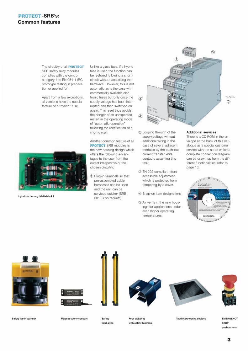
The circuitry of allSRB safety relay modulescomplies with the control category 4 to EN 954-1 (BGprototype testing in prepara-tion or applied for).
Apart from a few exceptions,all versions have the specialfeature of a “hybrid” fuse.
Unlike a glass fuse, if a hybridfuse is used the function canbe restored following a short-circuit without accessing thehardware. However, this is notautomatic as is the case withcommercially available elec-tronic fuses but only once thesupply voltage has been inter-rupted and then switched onagain. This reset thus avoidsthe danger of an unexpectedrestart in the operating modeof “automatic operation” following the rectification of ashort-circuit.
Another common feature of all SRB modules is
the new housing design whichoffers the following advan-tages to the user from theoutset irrespective of the chosen circuitry:
Plug-in terminals so thatpre-assembled cable harnesses can be usedand the unit can be serviced quicker (SRB301LC on request).
Looping through of thesupply voltage without additional wiring in thecase of several adjacentmodules by the push-outcurrent transfer knife contacts assuming thistask.
EN 292 compliant, frontaccessible adjustmentwhich is protected fromtampering by a cover.
Snap-on item designations.
Air vents in the new hous-ings for applications undereven higher operating temperatures.
Additional servicesThere is a CD ROM in the en-velope at the back of this cat-alogue as a special customerservice with the aid of which acomplete connection diagramcan be drawn up from the dif-ferent functionalities (refer topage 15).
Safety Relay Modules
Protect SRB series
Version 2.0 – August 2002
Ho
us
ing
Dim
en
sio
ns
an
d W
irin
g D
iag
ram
s System requirements
• Minimum Pentium 90 PC with 16 MB RAM
• Windows® 95 or higher• Windows® NT V3.51 or higher
• Acrobat Reader 4.0To install Acrobat Reader execute the file ACRD4ENU in the directory \ACROREAD on the CD-ROM.
Hybridsicherung: Maßstab 4:1
➀
➂
➃
➄
Tactile protective devices EMERGENCY
STOP
pushbuttons
Safety
light grids
Magnet safety sensorsSafety laser scanner Foot switches
with safety function
➁
➀
➁
➂
➃
➄
4
Multifunctionality is reflectedin the module developmentsSRB 308IT and SRB 219IT(for data sheet refer to page10 and 12 respectively) andrefers in particular to addition-al options concerning:
• Diagnosis and visualisation
• Potential uses
• Circuitry.
Increased availability ofmachines and controlsThe broad and easy to handlediagnostic features are theprime economic advantagesof these modules. These relate both to the relay cir-cuitry itself and the connectedperiphery.
Nearly every status in thesafety circuit can be incorpo-rated into the trouble-shootingmanagement part of a machine control via terminalsspecially provided for thistask.
• Fewer diagnostic contacts inthe form of additional PLCfeedback signals from thesensor/actuator level are re-quired.
• No additional bus interfaces.
• The need to interpret LEDfunction displays also losesimportance.
-SRB’s: Multifunctional versions
Universal possibilities of useAll commercially available protective devices with anelectro-mechanical principleof operation can be connect-ed to the SRB modules 308ITand 219IT, e.g. emergencystop control devices, inter-locking devices with or with-out locking, contact mats andsimilar, but also
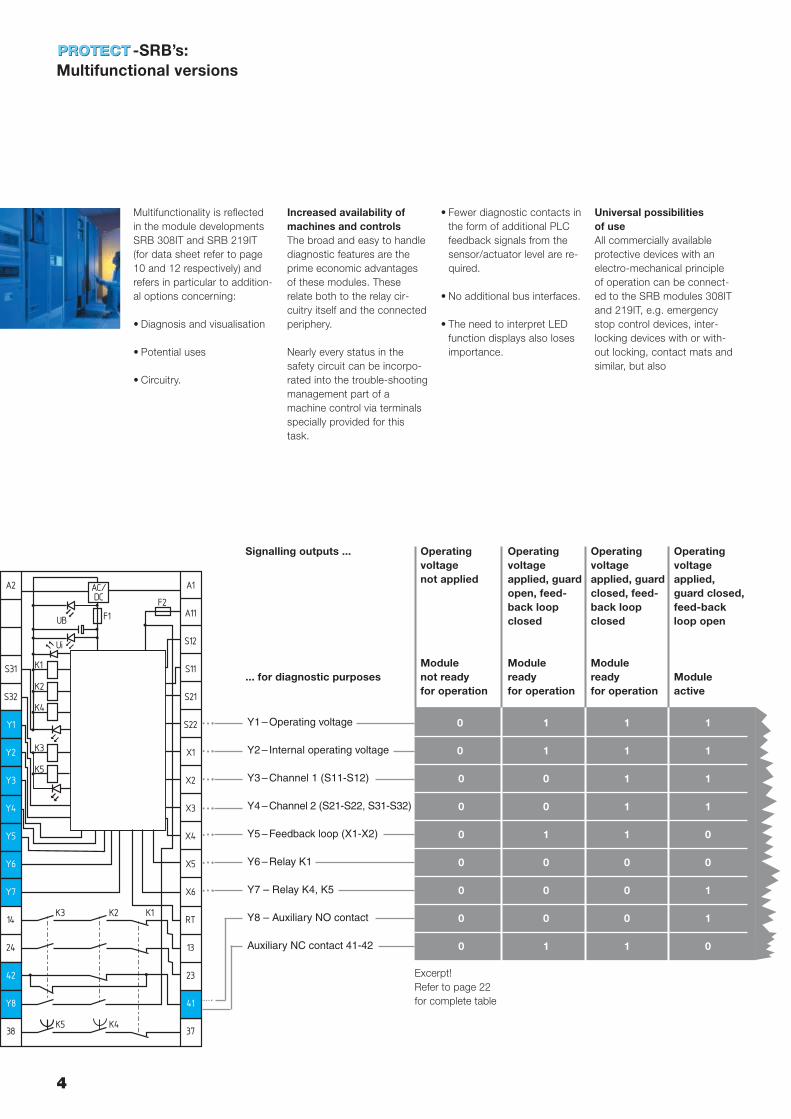
Operating voltage applied, guardopen, feed-back loop closed
Modulereadyfor operation
1
1
0
0
1
0
0
0
1
Operatingvoltagenot applied
Module not ready for operation
0
0
0
0
0
0
0
0
0
Operating voltage applied,guard closed,feed-backloop open
Moduleactive
1
1
1
1
0
0
1
1
0
Y1–Operating voltage
Y2– Internal operating voltage
Y3–Channel 1 (S11-S12)
Y4–Channel 2 (S21-S22, S31-S32)
Y5–Feedback loop (X1-X2)
Y6–Relay K1
Y7 – Relay K4, K5
Y8 – Auxiliary NO contact
Auxiliary NC contact 41-42
Operating voltage applied, guardclosed, feed-back loop closed
Modulereadyfor operation
1
1
1
1
1
0
0
0
1
Excerpt!Refer to page 22for complete table
Signalling outputs ...
... for diagnostic purposes
A2
S31 K1
K2
K4
K3
K5
S32
Y1
Y2
Y3
Y4
Y5
Y6
Y7
14
24
42
Y8
38
A1
F2
F1UB
Ui
A11
S12
S11
S21
S22
X1
X2
X3
X4
X5
X6
RT
13
23
41
37
AC/DC
K3 K2
K5 K4
K1
Guard
closed
K3
K2
K1
openedEnablingoutput
K1 K2 K3
K3 K2 K3 K3K1K2K1
K2 K1
S2
S1
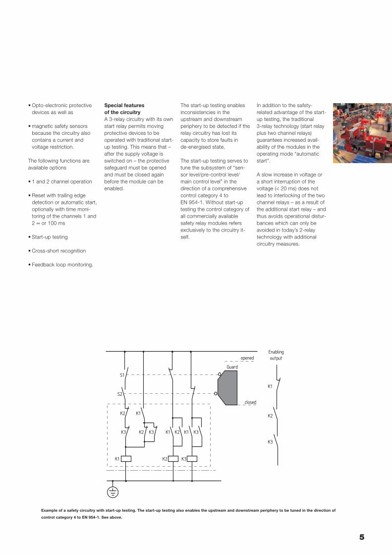
Example of a safety circuitry with start-up testing. The start-up testing also enables the upstream and downstream periphery to be tuned in the direction of
control category 4 to EN 954-1. See above.
5
• Opto-electronic protectivedevices as well as
• magnetic safety sensors because the circuitry alsocontains a current and voltage restriction.
The following functions areavailable options
• 1 and 2 channel operation
• Reset with trailing edge detection or automatic start,optionally with time moni-toring of the channels 1 and2 ∞ or 100 ms
• Start-up testing
• Cross-short recognition
• Feedback loop monitoring.
Special features of the circuitryA 3-relay circuitry with its ownstart relay permits movingprotective devices to be operated with traditional start-up testing. This means that –after the supply voltage isswitched on – the protectivesafeguard must be openedand must be closed again before the module can be enabled.
The start-up testing enablesinconsistencies in the upstream and downstreamperiphery to be detected if therelay circuitry has lost its capacity to store faults in de-energised state.
The start-up testing serves totune the subsystem of “sen-sor level/pre-control level/main control level” in the direction of a comprehensivecontrol category 4 to EN 954-1. Without start-uptesting the control category ofall commercially availablesafety relay modules refersexclusively to the circuitry it-self.
In addition to the safety-related advantage of the start-up testing, the traditional 3-relay technology (start relayplus two channel relays) guarantees increased avail-ability of the modules in theoperating mode “automaticstart”.
A slow increase in voltage ora short interruption of thevoltage (< 20 ms) does notlead to interlocking of the twochannel relays – as a result ofthe additional start relay – andthus avoids operational distur-bances which can only beavoided in today’s 2-relaytechnology with additional circuitry measures.
6
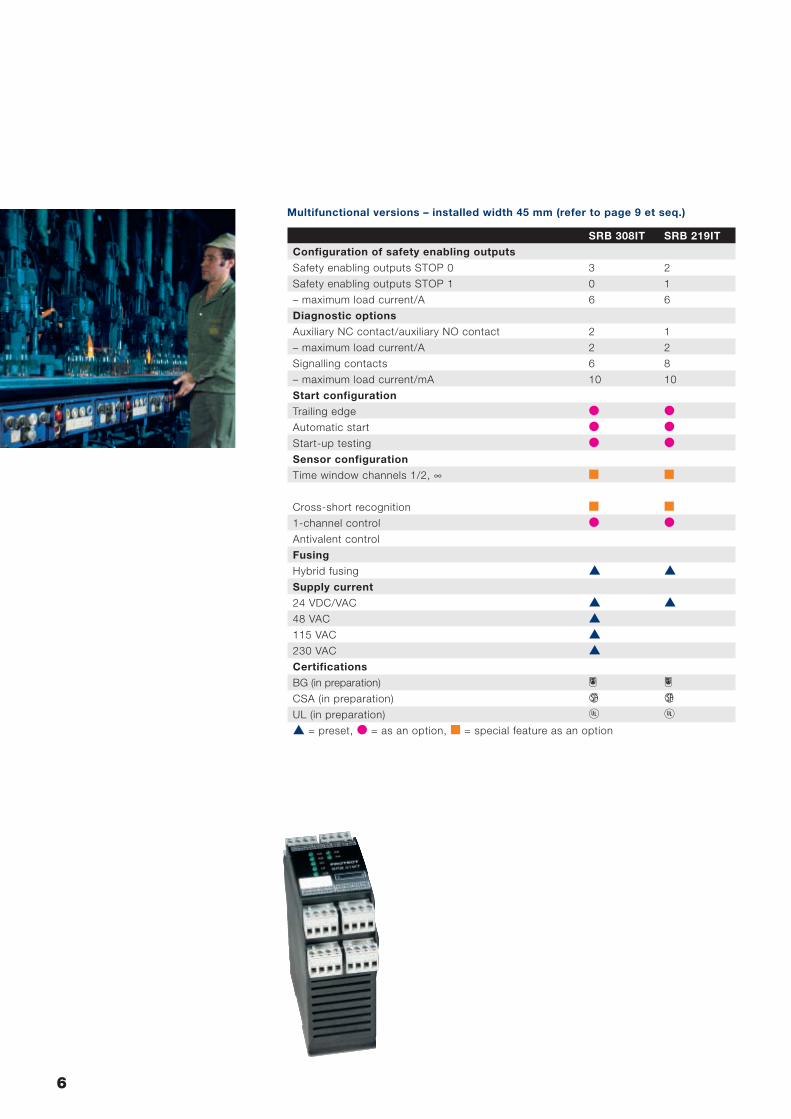
Multifunctional versions – installed width 45 mm (refer to page 9 et seq.)
SRB 308IT SRB 219IT
Configuration of safety enabling outputs
Safety enabling outputs STOP 0 3 2
Safety enabling outputs STOP 1 0 1
– maximum load current/A 6 6
Diagnostic options
Auxiliary NC contact/auxiliary NO contact 2 1
– maximum load current/A 2 2
Signalling contacts 6 8
– maximum load current/mA 10 10
Start configuration
Trailing edge � �Automatic start � �Start-up testing � �Sensor configuration
Time window channels 1/2, ∞ � �
Cross-short recognition � �1-channel control � �Antivalent control
Fusing
Hybrid fusing Supply current
24 VDC/VAC 48 VAC 115 VAC 230 VAC Certifications
BG (in preparation) H HCSA (in preparation) D DUL (in preparation) C C = preset, � = as an option, � = special feature as an option
7
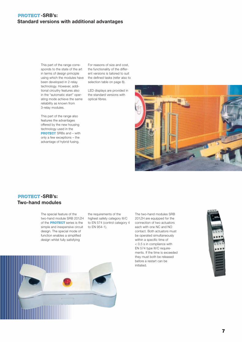
This part of the range corre-sponds to the state of the artin terms of design principleusing which the modules havebeen developed in 2-relaytechnology. However, addi-tional circuitry features also in the “automatic start” oper-ating mode achieve the samereliability as known from 3-relay modules.
This part of the range alsofeatures the advantages offered by the new housingtechnology used in the
SRBs and – withonly a few exceptions – theadvantage of hybrid fusing.
For reasons of size and cost,the functionality of the differ-ent versions is tailored to suitthe defined tasks (refer also toselection table on page 8).
LED displays are provided inthe standard versions withoptical fibres.
The special feature of thetwo-hand module SRB 201ZHof the series is thesimple and inexpensive circuitdesign. The special mode offunction enables a simplifieddesign whilst fully satisfying
-SRB’s: Standard versions with additional advantages
The two-hand modules SRB201ZH are equipped for theconnection of two actuatorseach with one NC and NOcontact. Both actuators mustbe operated simultaneouslywithin a specific time of < 0.5 s in compliance with EN 574 type III/C require-ments. If the time is exceededthey must both be releasedbefore a restart can be initiated.
the requirements of the highest safety category III/Cto EN 574 (control category 4to EN 954-1).
-SRB’s: Two-hand modules
8
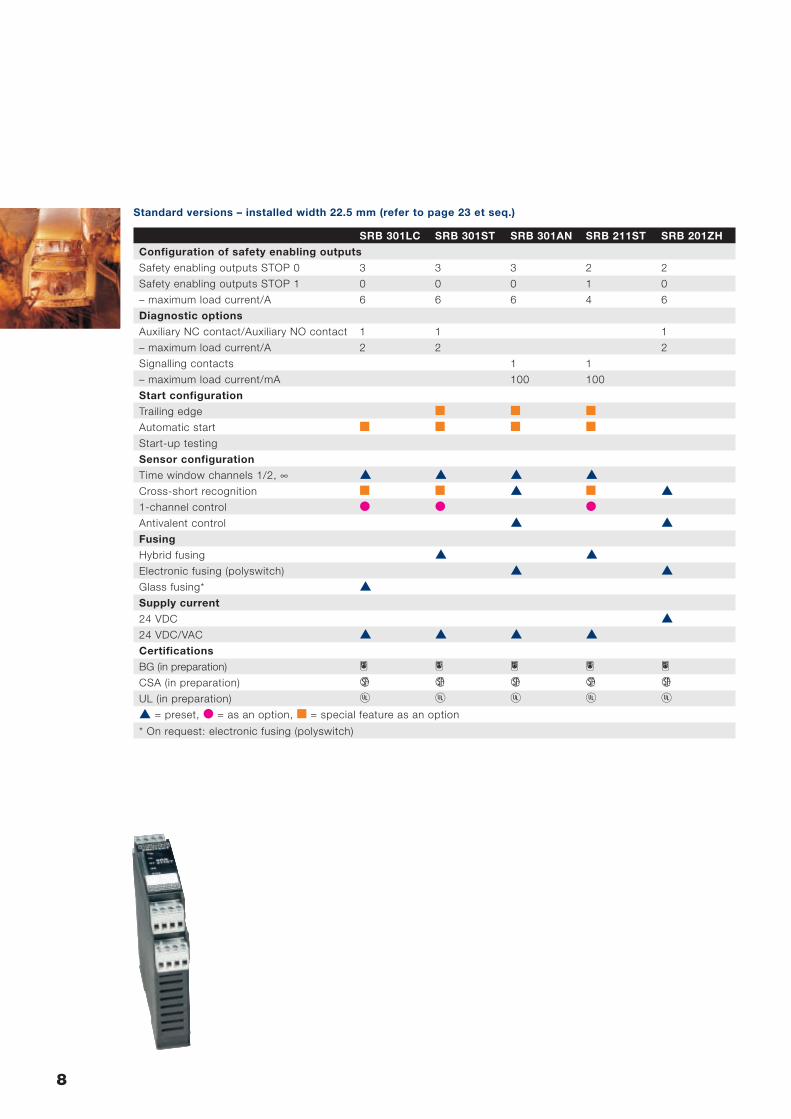
Standard versions – installed width 22.5 mm (refer to page 23 et seq.)
SRB 301LC SRB 301ST SRB 301AN SRB 211ST SRB 201ZH
Configuration of safety enabling outputs
Safety enabling outputs STOP 0 3 3 3 2 2
Safety enabling outputs STOP 1 0 0 0 1 0
– maximum load current/A 6 6 6 4 6
Diagnostic options
Auxiliary NC contact/Auxiliary NO contact 1 1 1
– maximum load current/A 2 2 2
Signalling contacts 1 1
– maximum load current/mA 100 100
Start configuration
Trailing edge � � �Automatic start � � � �Start-up testing
Sensor configuration
Time window channels 1/2, ∞ Cross-short recognition � � � 1-channel control � � �Antivalent control Fusing
Hybrid fusing Electronic fusing (polyswitch) Glass fusing* Supply current
24 VDC 24 VDC/VAC Certifications
BG (in preparation) H H H H HCSA (in preparation) D D D D DUL (in preparation) C C C C C = preset, � = as an option, � = special feature as an option
* On request: electronic fusing (polyswitch)
9
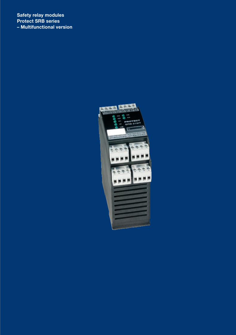
Safety relay modulesProtect SRB series – Multifunctional version
10 Schmersal Industrial switching systems
34 Y1
SRB 308IT
24
Y2
K3
K2
K1
Ui
UB
14 Y3 42
Y5
X1
X2
X3
X4
Y4
X5
X6
S11
A2
A133 Y6
S12
23
A1.1
13 41
53
54S21
S31
S22
S32
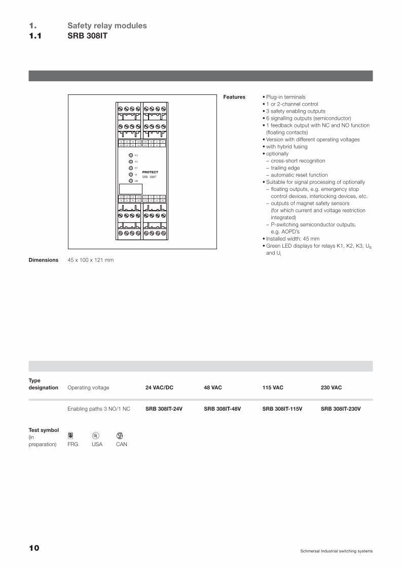
Safety relay modulesSRB 308IT
1.1.1
Features • Plug-in terminals• 1 or 2-channel control• 3 safety enabling outputs• 6 signalling outputs (semiconductor)• 1 feedback output with NC and NO function
(floating contacts)• Version with different operating voltages• with hybrid fusing• optionally
– cross-short recognition– trailing edge– automatic reset function
• Suitable for signal processing of optionally– floating outputs, e.g. emergency stop
control devices, interlocking devices, etc.– outputs of magnet safety sensors
(for which current and voltage restrictionintegrated)
– P-switching semiconductor outputs, e.g. AOPD’s
• Installed width: 45 mm• Green LED displays for relays K1, K2, K3, UB
and Ui45 x 100 x 121 mmDimensions
H C DFRG USA CAN
Test symbol(in preparation)
24 VAC/DC
SRB 308IT-24V
Operating voltageTypedesignation 48 VAC
SRB 308IT-48V
115 VAC
SRB 308IT-115V
230 VAC
SRB 308IT-230VEnabling paths 3 NO/1 NC
11Schmersal Industrial switching systems
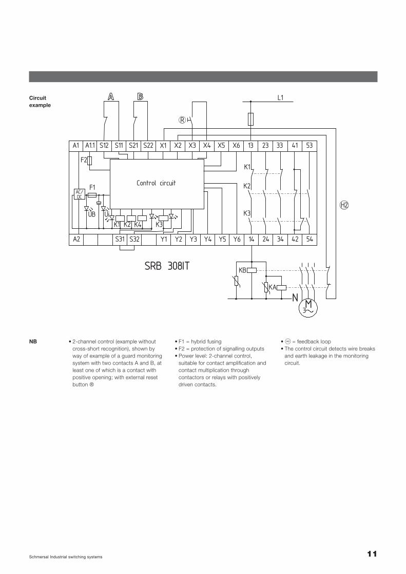
Circuitexample
SRB 308IT
L1
K2
K1
K3
K1 K4K2 K3
34
5341
5442
23
24
13S22S21S11S12A1 A1.1
F2
X1 X2 X3 X4 X5 X6 33
14S31 S32 Y1 Y5Y3A2
F1AC/DC
UiUB
Control circuit
Y4Y2 Y6
R
H2
M3
KA
N
KB
• 2-channel control (example withoutcross-short recognition), shown byway of example of a guard monitoringsystem with two contacts A and B, atleast one of which is a contact withpositive opening; with external resetbutton ®
NB • S = feedback loop• The control circuit detects wire breaks
and earth leakage in the monitoringcircuit.
• F1 = hybrid fusing• F2 = protection of signalling outputs• Power level: 2-channel control,
suitable for contact amplification andcontact multiplication through contactors or relays with positively driven contacts.
SRB 219ITt: s
K3
K2
K5
K4
K1
Ui
UB
37 13 23 X5 X3 Y6 41 A1
S32 S31 X6 X4 X2 Y5 Y8 Y7
S22 S21 S12 S11 Y4 Y2 RT A11
38 14 24 X1 Y3 Y1 42 A2
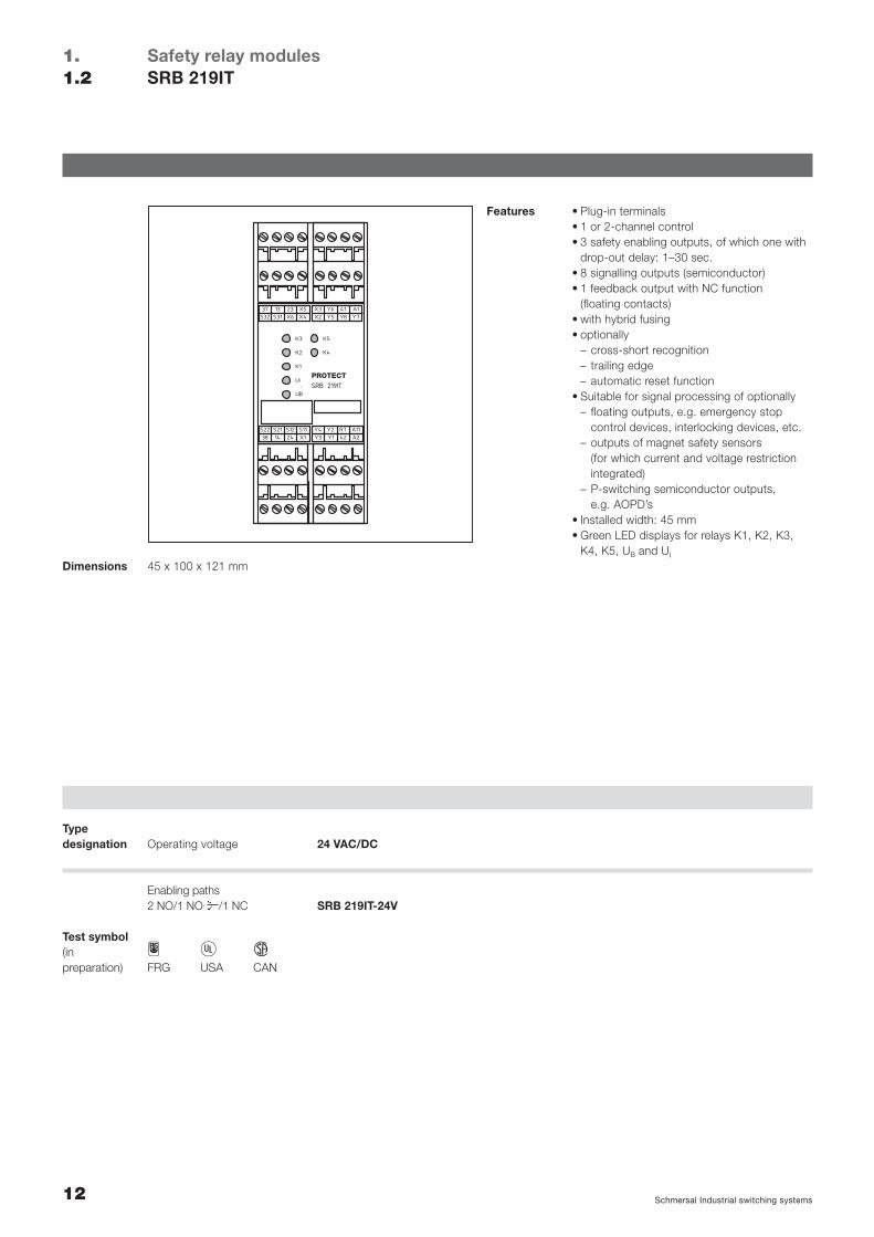
Enabling paths2 NO/1 NO /1 NC
12 Schmersal Industrial switching systems
Safety relay modulesSRB 219IT
1.1.2
Features • Plug-in terminals• 1 or 2-channel control• 3 safety enabling outputs, of which one with
drop-out delay: 1–30 sec.• 8 signalling outputs (semiconductor)• 1 feedback output with NC function
(floating contacts)• with hybrid fusing• optionally
– cross-short recognition– trailing edge– automatic reset function
• Suitable for signal processing of optionally– floating outputs, e.g. emergency stop
control devices, interlocking devices, etc.– outputs of magnet safety sensors
(for which current and voltage restrictionintegrated)
– P-switching semiconductor outputs, e.g. AOPD’s
• Installed width: 45 mm• Green LED displays for relays K1, K2, K3,
K4, K5, UB and Ui45 x 100 x 121 mmDimensions
H C DFRG USA CAN
Test symbol(in preparation)
24 VAC/DC
SRB 219IT-24V
Operating voltageTypedesignation
13Schmersal Industrial switching systems
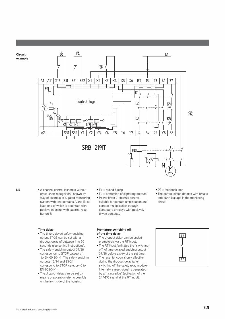
Circuitexample
SRB 219IT
L1
K2
K1
K3 K5
K4
K1 K4K2 K3 K5
42
3741
38Y8
23
24
13S22S11 S21S12A1 A1.1
F2
X1 X2 X3 X4 X5 X6 RT
14S31 S32 Y1 Y5Y3 Y7A2
F1AC/DC
UiUB
Control logic
Y4Y2 Y6
KB
KA
3
NM
H2
R
• 2-channel control (example withoutcross-short recognition), shown byway of example of a guard monitoringsystem with two contacts A and B, atleast one of which is a contact withpositive opening; with external resetbutton ®
NB • S = feedback loop• The control circuit detects wire breaks
and earth leakage in the monitoringcircuit.
• F1 = hybrid fusing• F2 = protection of signalling outputs• Power level: 2-channel control,
suitable for contact amplification andcontact multiplication through contactors or relays with positively driven contacts.
Time delay• The time-delayed safety enabling
output 37/38 can be set with adropout delay of between 1 to 30seconds (see setting instructions).
• The safety enabling output 37/38corresponds to STOP category 1to EN 60 204-1. The safety enabling
outputs 13/14 and 23/24 correspond to STOP category 0 toEN 60204-1.
• The dropout delay can be set bymeans of potentiometer accessibleon the front side of the housing.
Premature switching off of the time delay • The dropout delay can be ended
prematurely via the RT input.• The RT input facilitates the “switching
off” of time-delayed enabling output37/38 before expiry of the set time.
• The reset function is only effective during the dropout delay (after switching off the safety relay module).Internally a reset signal is generated by a “rising edge” (activation of the 24 VDC signal at the RT input).
RT
S11
14 Schmersal Industrial switching systems
Safety relay modulesTechnical data
1.1.3
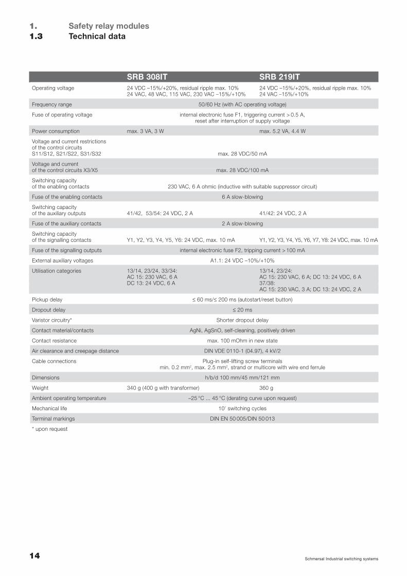
SRB 308IT SRB 219ITOperating voltage 24 VDC –15%/+20%, residual ripple max. 10% 24 VDC –15%/+20%, residual ripple max. 10%
24 VAC, 48 VAC, 115 VAC, 230 VAC –15%/+10% 24 VAC –15%/+10%
Frequency range 50/60 Hz (with AC operating voltage)
Fuse of operating voltage internal electronic fuse F1, triggering current > 0.5 A,reset after interruption of supply voltage
Power consumption max. 3 VA, 3 W max. 5.2 VA, 4.4 W
Voltage and current restrictionsof the control circuitsS11/S12, S21/S22, S31/S32 max. 28 VDC/50 mA
Voltage and currentof the control circuits X3/X5 max. 28 VDC/100 mA
Switching capacity of the enabling contacts 230 VAC, 6 A ohmic (inductive with suitable suppressor circuit)
Fuse of the enabling contacts 6 A slow-blowing
Switching capacityof the auxiliary outputs 41/42, 53/54: 24 VDC, 2 A 41/42: 24 VDC, 2 A
Fuse of the auxiliary contacts 2 A slow-blowing
Switching capacityof the signalling contacts Y1, Y2, Y3, Y4, Y5, Y6: 24 VDC, max. 10 mA Y1, Y2, Y3, Y4, Y5, Y6, Y7, Y8: 24 VDC, max. 10 mA
Fuse of the signalling outputs internal electronic fuse F2, tripping current > 100 mA
External auxiliary voltages A1.1: 24 VDC –10%/+10%
Utilisation categories 13/14, 23/24, 33/34: 13/14, 23/24: AC 15: 230 VAC, 6 A AC 15: 230 VAC, 6 A; DC 13: 24 VDC, 6 ADC 13: 24 VDC, 6 A 37/38:
AC 15: 230 VAC, 3 A; DC 13: 24 VDC, 2 A
Pickup delay ≤ 60 ms/≤ 200 ms (autostart/reset button)
Dropout delay ≤ 20 ms
Varistor circuitry* Shorter dropout delay
Contact material/contacts AgNi, AgSnO, self-cleaning, positively driven
Contact resistance max. 100 mOhm in new state
Air clearance and creepage distance DIN VDE 0110-1 (04.97), 4 kV/2
Cable connections Plug-in self-lifting screw terminals min. 0.2 mm2, max. 2.5 mm2, strand or multicore with wire end ferrule
Dimensions h/b/d 100 mm/45 mm/121 mm
Weight 340 g (400 g with transformer) 360 g
Ambient operating temperature –25 °C ... 45 °C (derating curve upon request)
Mechanical life 107 switching cycles
Terminal markings DIN EN 50 005/DIN 50 013
* upon request
15Schmersal Industrial switching systems
Safety relay modulesSelection of applications
1.1.4
1.4 Selection of applications
Start configurationExternal reset button . . . . . . . . . . . . . . . . . . . . . . . . . . . . . . . . . . . . . . . . . . . . . . . . Page 16Automatic (time offset approx. 100 ms) . . . . . . . . . . . . . . . . . . . . . . . . . . . . . . . . . . . Page 16Start-up testing . . . . . . . . . . . . . . . . . . . . . . . . . . . . . . . . . . . . . . . . . . . . . . . . . . . . Page 16
Sensor configurationEMERGENCY-STOP . . . . . . . . . . . . . . . . . . . . . . . . . . . . . . . . . . . . . . . . . . . . . . . . Page 17Guard . . . . . . . . . . . . . . . . . . . . . . . . . . . . . . . . . . . . . . . . . . . . . . . . . . . . . . . . . . Page 18P-switching semiconductor . . . . . . . . . . . . . . . . . . . . . . . . . . . . . . . . . . . . . . . . . . . Page 19Magnetic safety sensors . . . . . . . . . . . . . . . . . . . . . . . . . . . . . . . . . . . . . . . . . . . . . Page 19
Actuator configuration/contact multiplication (KV)Single-channel . . . . . . . . . . . . . . . . . . . . . . . . . . . . . . . . . . . . . . . . . . . . . . . . . . . . Page 20Dual-channel . . . . . . . . . . . . . . . . . . . . . . . . . . . . . . . . . . . . . . . . . . . . . . . . . . . . . Page 20Diversitary . . . . . . . . . . . . . . . . . . . . . . . . . . . . . . . . . . . . . . . . . . . . . . . . . . . . . . . Page 20
The following selection of applicationsis intended to provide users with assistance on which functionalitiesPROTECT SRBs offer.
The circuit examples are suggestionswhich do not (cannot), however, release the user from his own responsibility to check the circuitrycarefully in terms of its suitability forthe individual case.
SRB 308IT
L1
K2
K1
K3
K1 K4K2 K3
34
5341
5442
23
24
13S22S11 S21S12A1 A1.1
F2
X1 X2 X3 X4 X5 X6 33
14S31 S32 Y1 Y5Y3A2
F1AC/DC
UiUB
Control circuit
Y4Y2 Y6
R
H2
M3
KA
N
KB
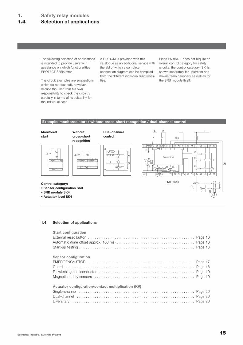
Example: monitored start / without cross-short recognition / dual-channel control
S21 S22 S31 S32S12S11
Y3 Y4
14
13X2X1KA
KA
KA KB
KB
KB
L1
N
Monitoredstart
Withoutcross-shortrecognition
Dual-channelcontrol
K
K
A
B
R
X1X3 X4 X2
Y5Y6
Control category:• Sensor configuration SK3• SRB module SK4• Actuator level SK4
A CD ROM is provided with this catalogue as an additional service withthe aid of which a complete connection diagram can be compiledfrom the different individual functionali-ties.
Since EN 954-1 does not require anoverall control category for safety circuits, the control category (SK) isshown separately for upstream anddownstream periphery as well as forthe SRB module itself.
16 Schmersal Industrial switching systems
Start configuration
Safety relay modulesSelection of applications
1.1.4
R
X4
Y6
Signalling output
AF01
X3
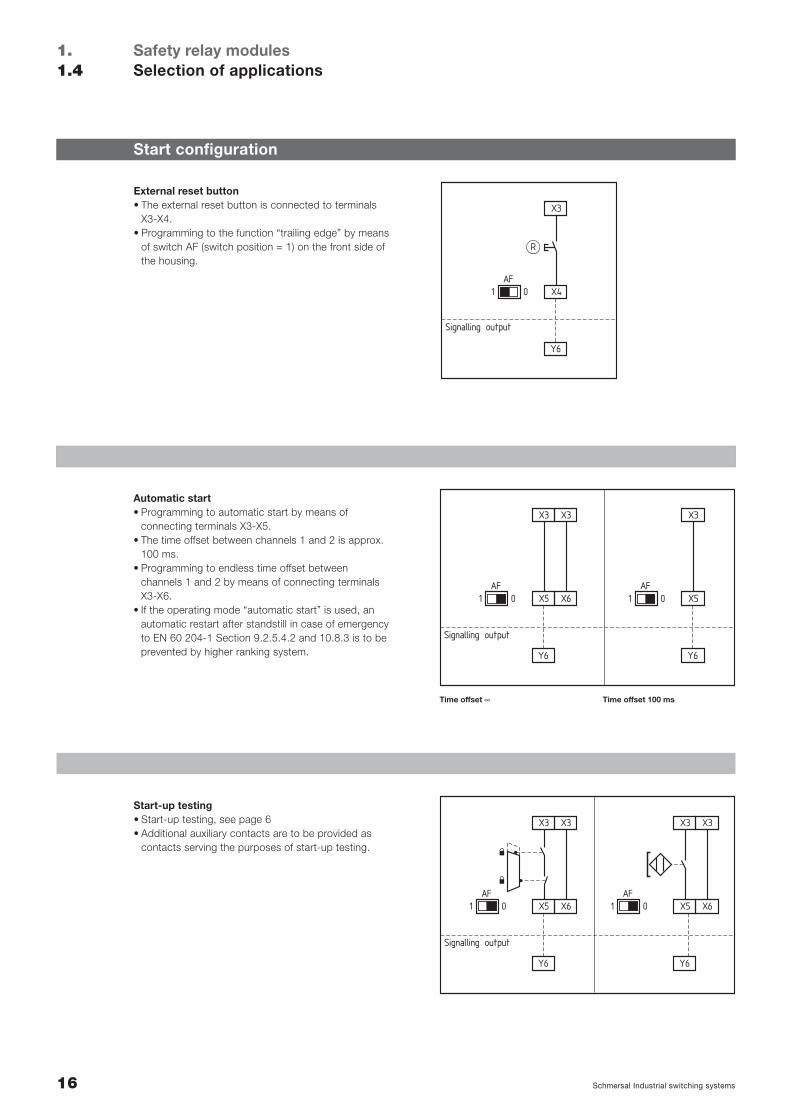
External reset button• The external reset button is connected to terminals
X3-X4.• Programming to the function “trailing edge” by means
of switch AF (switch position = 1) on the front side ofthe housing.
X5
Y6
AF01
X3
X6
X3
Y6
AF01 X5
X3
Signalling output
Automatic start• Programming to automatic start by means of
connecting terminals X3-X5.• The time offset between channels 1 and 2 is approx.
100 ms.• Programming to endless time offset between
channels 1 and 2 by means of connecting terminalsX3-X6.
• If the operating mode “automatic start” is used, anautomatic restart after standstill in case of emergencyto EN 60 204-1 Section 9.2.5.4.2 and 10.8.3 is to beprevented by higher ranking system.
X5
Y6
AF01
X3
X6
X3
X5
Y6
AF01
X3
X6
X3
Signalling output
Start-up testing• Start-up testing, see page 6• Additional auxiliary contacts are to be provided as
contacts serving the purposes of start-up testing.
Time offset ∞ Time offset 100 ms

17Schmersal Industrial switching systems
Sensor configuration
S12
Y3 Y4
S11
S22
S12
S32
S31
Signallingoutputs
A
Single-channel EMERGENCY STOP circuit to EN 418/EN 60 947-5-5• Detects wire break and earth leakage in
EMERGENCY STOP circuit.
S12
Y3 Y4
S11
S22
S21
S32
S31
Signallingoutputs
A B
Dual-channel EMERGENCY STOP circuit to EN 418/EN 60 947-5-5• Detects wire break and earth leakage in the
EMERGENCY STOP circuits.• Cross shorts in the EMERGENCY STOP circuits
are not detected.
S12
Y3 Y4
S11
S22
S21
S32
S31
A B
Signallingoutputs
Dual-channel EMERGENCY STOP circuit to EN 418/EN 60 947-5-5• Detects wire breaks and earth leakage in the
EMERGENCY STOP circuits.• Cross shorts in the EMERGENCY STOP circuits
are detected.
18 Schmersal Industrial switching systems
Safety relay modulesSelection of applications
1.1.4
S12
Y3 Y4
S11
S22
S12
S32
S31
A
Signallingoutputs
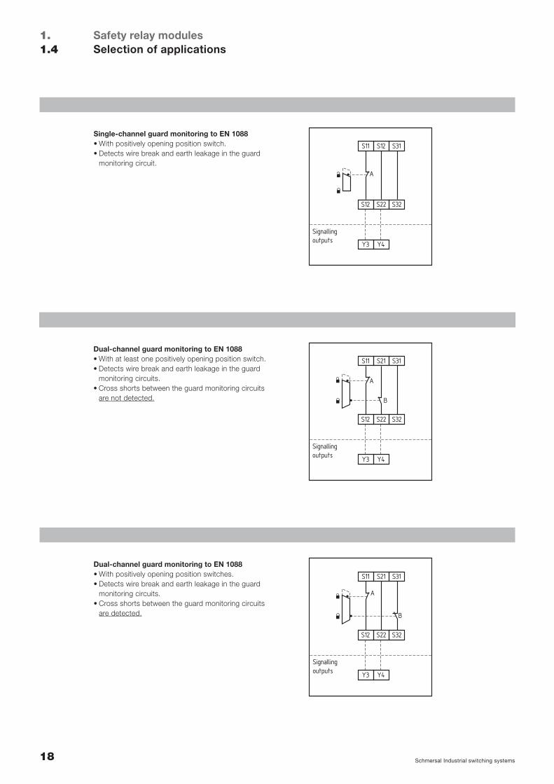
Single-channel guard monitoring to EN 1088• With positively opening position switch.• Detects wire break and earth leakage in the guard
monitoring circuit.
S12
Y3 Y4
S11
S22
S21
S32
S31
A
Signallingoutputs
B
Dual-channel guard monitoring to EN 1088• With at least one positively opening position switch.• Detects wire break and earth leakage in the guard
monitoring circuits.• Cross shorts between the guard monitoring circuits
are not detected.
S12
Y3 Y4
S11
S22
S21
S32
S31
A
B
Signallingoutputs
Dual-channel guard monitoring to EN 1088• With positively opening position switches.• Detects wire break and earth leakage in the guard
monitoring circuits.• Cross shorts between the guard monitoring circuits
are detected.
19Schmersal Industrial switching systems
S12
Y3 Y4
S11
S22
S21
S32
S31
Signallingoutputs
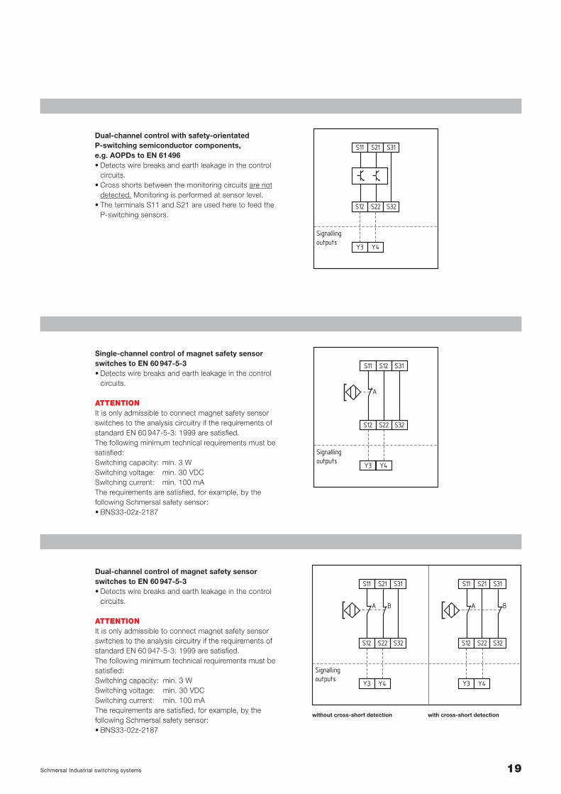
Dual-channel control with safety-orientated P-switching semiconductor components, e.g. AOPDs to EN 61496• Detects wire breaks and earth leakage in the control
circuits.• Cross shorts between the monitoring circuits are not
detected. Monitoring is performed at sensor level.• The terminals S11 and S21 are used here to feed the
P-switching sensors.
S12
Y3 Y4
S11
S22
S12
S32
S31
Signallingoutputs
A
Single-channel control of magnet safety sensorswitches to EN 60 947-5-3• Detects wire breaks and earth leakage in the control
circuits.
ATTENTIONIt is only admissible to connect magnet safety sensorswitches to the analysis circuitry if the requirements ofstandard EN 60 947-5-3: 1999 are satisfied.The following minimum technical requirements must besatisfied:Switching capacity: min. 3 WSwitching voltage: min. 30 VDCSwitching current: min. 100 mAThe requirements are satisfied, for example, by the following Schmersal safety sensor:• BNS33-02z-2187
S12
Y3 Y4
S11
S22
S21
S32
S31
A B
S12
Y3 Y4
S11
S22
S21
S32
S31
A B
Signallingoutputs
Dual-channel control of magnet safety sensorswitches to EN 60 947-5-3• Detects wire breaks and earth leakage in the control
circuits.
ATTENTIONIt is only admissible to connect magnet safety sensorswitches to the analysis circuitry if the requirements ofstandard EN 60 947-5-3: 1999 are satisfied.The following minimum technical requirements must besatisfied:Switching capacity: min. 3 WSwitching voltage: min. 30 VDCSwitching current: min. 100 mAThe requirements are satisfied, for example, by the following Schmersal safety sensor:• BNS33-02z-2187
without cross-short detection with cross-short detection
Schmersal Industrial switching systems
Actuator configuration
Safety relay modulesSelection of applications
1.1.4
KA KC
X1 X2
14
13
38
37
KA KC
KA
L1
N
*KC
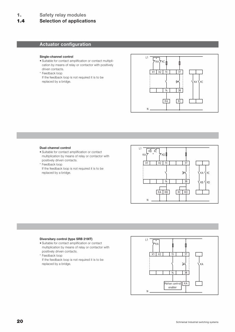
Single-channel control• Suitable for contact amplification or contact multipli-
cation by means of relay or contactor with positivelydriven contacts.
* Feedback loopIf the feedback loop is not required it is to be replaced by a bridge.
KB KD
X1 X2
14
13
38
37
KA KC
KB KD
KAKB KC
L1
N
* KD
KA KC
Dual-channel control• Suitable for contact amplification or contact
multiplication by means of relay or contactor withpositively driven contacts.
* Feedback loopIf the feedback loop is not required it is to be replaced by a bridge.
Motion controlenabler
KA
X1 X2
14
13
38
37
KA
KA
L1
N
*Diversitary control (type SRB 219IT)• Suitable for contact amplification or contact
multiplication by means of relay or contactor withpositively driven contacts.
* Feedback loopIf the feedback loop is not required it is to be replaced by a bridge.
20
21Schmersal Industrial switching systems
Terminal designation
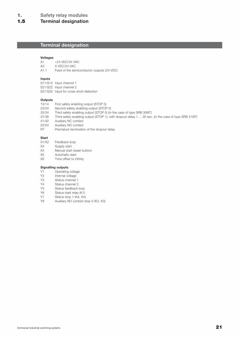
VoltagesA1 +24 VDC/24 VACA2 0 VDC/24 VACA1.1 Feed of the semiconductor outputs (24 VDC)
InputsS11/S12 Input channel 1S21/S22 Input channel 2S31/S32 Input for cross-short detection
Outputs13/14 First safety enabling output (STOP 0)23/24 Second safety enabling output (STOP 0)33/34 Third safety enabling output (STOP 0) (in the case of type SRB 308IT)37/38 Third safety enabling output (STOP 1), with dropout delay 1 ... 30 sec. (in the case of type SRB 219IT)41/42 Auxiliary NC contact53/54 Auxiliary NO contactRT Premature termination of the dropout delay
StartX1/X2 Feedback loopX3 Supply startX4 Manual start (reset button)X5 Automatic startX6 Time offset to infinity
Signalling outputsY1 Operating voltageY2 Internal voltageY3 Status channel 1Y4 Status channel 2Y5 Status feedback loopY6 Status start relay (K1)Y7 Status stop 1 (K4, K5)Y8 Auxiliary NO contact stop 0 (K2, K3)
Safety relay modulesTerminal designation
1.1.5
22 Schmersal Industrial switching systems
Safety relay modulesDiagnosis tables
1.1.6
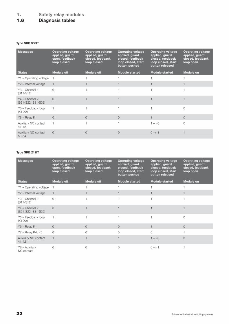
Messages Operating voltage Operating voltage Operating voltage Operating voltage Operating voltageapplied, guard applied, guard applied, guard applied, guard applied, guardopen, feedback closed, feedback closed, feedback closed, feedback closed, feedbackloop closed loop closed loop closed, start loop closed, start loop open
button pushed button released
Status Module off Module off Module started Module started Module on
Y1 – Operating voltage 1 1 1 1 1
Y2 – Internal voltage 1 1 1 1 1
Y3 – Channel 1 0 1 1 1 1(S11-S12)
Y4 – Channel 2 0 1 1 1 1(S21-S22, S31-S32)
Y5 – Feedback loop 1 1 1 1 0(X1-X2)
Y6 – Relay K1 0 0 0 1 0
Y7 – Relay K4, K5 0 0 0 0 1
Auxiliary NC contact 1 1 1 1 –> 0 041-42
Y8 – Auxiliary 0 0 0 0 –> 1 1NO contact
Messages Operating voltage Operating voltage Operating voltage Operating voltage Operating voltageapplied, guard applied, guard applied, guard applied, guard applied, guardopen, feedback closed, feedback closed, feedback closed, feedback closed, feedbackloop closed loop closed loop closed, start loop closed, start loop open
button pushed button released
Status Module off Module off Module started Module started Module on
Y1 – Operating voltage 1 1 1 1 1
Y2 – Internal voltage 1 1 1 1 1
Y3 – Channel 1 0 1 1 1 1(S11-S12)
Y4 – Channel 2 0 1 1 1 1(S21-S22, S31-S32)
Y5 – Feedback loop 1 1 1 1 0(X1-X2)
Y6 – Relay K1 0 0 0 1 0
Auxiliary NC contact 1 1 1 1 –> 0 041-42
Auxiliary NO contact 0 0 0 0 –> 1 153-54
Type SRB 308IT
Type SRB 219IT
Safety relay modulesProtect SRB series– Standard version
24 Schmersal Industrial switching systems
UB
Ui
K1
K2
33 23 13 41X1
X2 S22 S21 A234 24 14 42
S12 S11 A1
PROTECTSRB 301LC
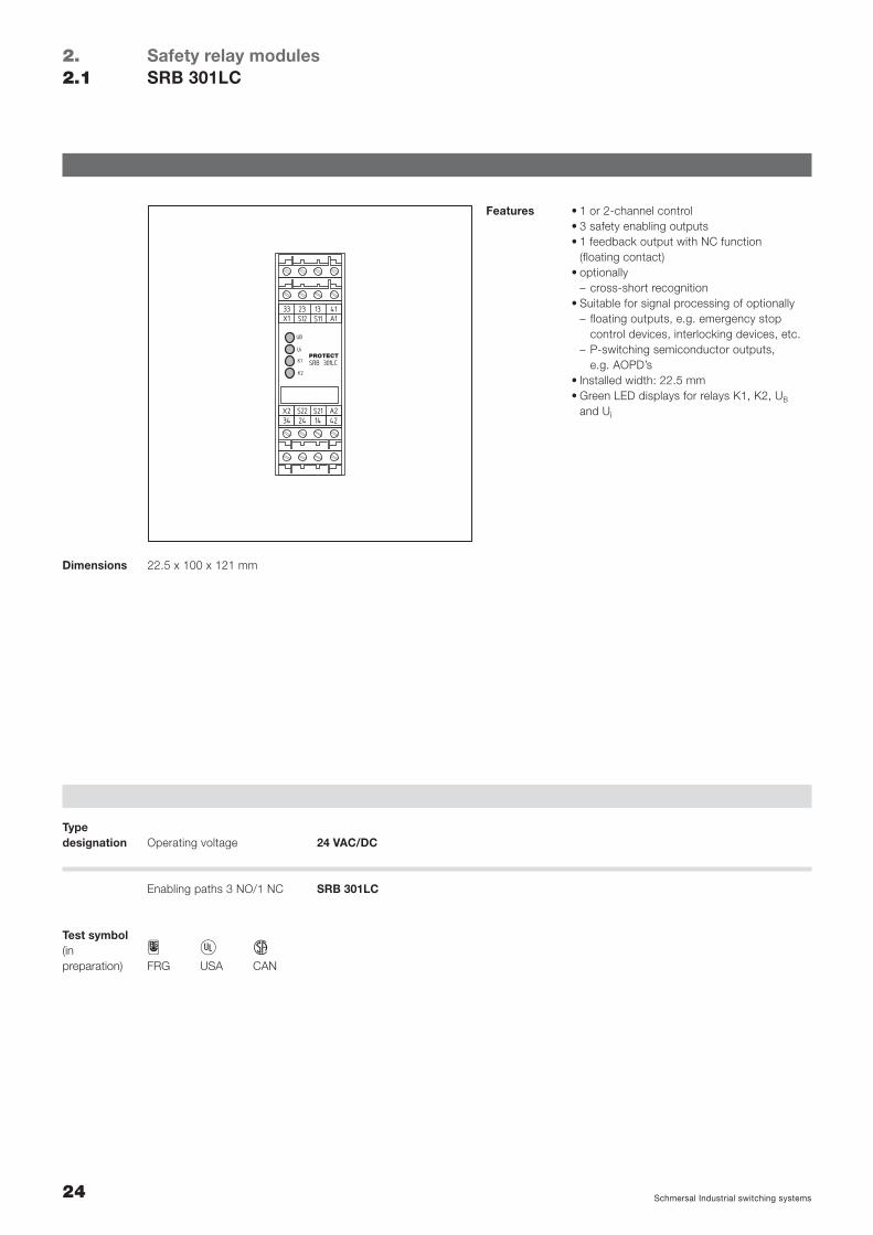
Safety relay modulesSRB 301LC
2.2.1
Features • 1 or 2-channel control• 3 safety enabling outputs• 1 feedback output with NC function
(floating contact)• optionally
– cross-short recognition• Suitable for signal processing of optionally
– floating outputs, e.g. emergency stop control devices, interlocking devices, etc.
– P-switching semiconductor outputs, e.g. AOPD’s
• Installed width: 22.5 mm• Green LED displays for relays K1, K2, UB
and Ui
22.5 x 100 x 121 mmDimensions
H C DFRG USA CAN
Test symbol(in preparation)
24 VAC/DC
SRB 301LC
Operating voltageTypedesignation
Enabling paths 3 NO/1 NC
25Schmersal Industrial switching systems
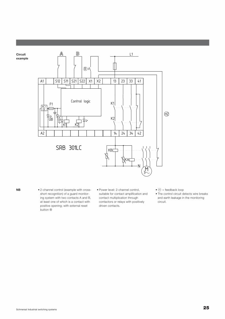
Circuitexample
SRB 301LC
L1
K1
K2
K1 K2
34
41
42
23
24
13S22S21S11S12A1 X1 X2 33
14A2
F1AC/DC
UiUB
Control logic
R
H2
M3
KA
N
KB
• 2-channel control (example with cross-short recognition) of a guard monitor-ing system with two contacts A and B,at least one of which is a contact with positive opening; with external reset button ®
NB • S = feedback loop• The control circuit detects wire breaks
and earth leakage in the monitoringcircuit.
• Power level: 2-channel control, suitable for contact amplification andcontact multiplication through contactors or relays with positively driven contacts.

26 Schmersal Industrial switching systems
PROTECTSRB 301ST
UB
Ui
K1
K2
33 23 13 41X2
X3 S22 S21 A234 24 14 42
S12 S11 A1
Safety relay modulesSRB 301ST
2.2.2
Features • Plug-in terminals• 1 or 2-channel control• 3 safety enabling outputs• 1 feedback output with NC function
(floating contact)• with hybrid fusing• optionally
– cross-short recognition– trailing edge– automatic reset function
• Suitable for signal processing of optionally – floating outputs, e.g. emergency stop
control devices, interlocking devices, etc.– P-switching semiconductor outputs,
e.g. AOPD’s• Installed width: 22.5 mm• Green LED displays for relays K1, K2, UB
and Ui
22.5 x 100 x 121 mmDimensions
H C DFRG USA CAN
Test symbol(inpreparation)
24 VAC/DC
SRB 301ST
Operating voltageTypedesignation
Enabling paths 3 NO/1 NC
27Schmersal Industrial switching systems
Circuitexample
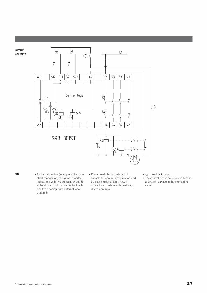
SRB 301ST
L1
K1
K2
K1 K2
34
41
42
23
24
13S22S21S11S12A1 X2 33
14A2
F1AC/DC
UiUB
R
H2
M3
KA
N
KB
Control logic
• 2-channel control (example with cross-short recognition) of a guard monitor-ing system with two contacts A and B,at least one of which is a contact withpositive opening; with external resetbutton ®
NB • S = feedback loop• The control circuit detects wire breaks
and earth leakage in the monitoringcircuit.
• Power level: 2-channel control, suitable for contact amplification andcontact multiplication through contactors or relays with positively driven contacts.
28 Schmersal Industrial switching systems
PROTECTSRB 301AN
K1
Ui
K2
13 23 33 Y1A1
A2 S21 S22 S1414 24 34 S13
X1 X2 X3
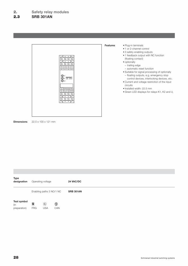
Safety relay modulesSRB 301AN
2.2.3
Features • Plug-in terminals• 1 or 2-channel control• 3 safety enabling outputs• 1 feedback output with NC function
(floating contact) • optionally
– trailing edge– automatic reset function
• Suitable for signal processing of optionally– floating outputs, e.g. emergency stop
control devices, interlocking devices, etc.• Current and voltage restriction of the input
circuits• Installed width: 22.5 mm• Green LED displays for relays K1, K2 and Ui
22.5 x 100 x 121 mmDimensions
H C DFRG USA CAN
Test symbol(in preparation)
24 VAC/DC
SRB 301AN
Operating voltageTypedesignation
Enabling paths 3 NO/1 NC
29Schmersal Industrial switching systems
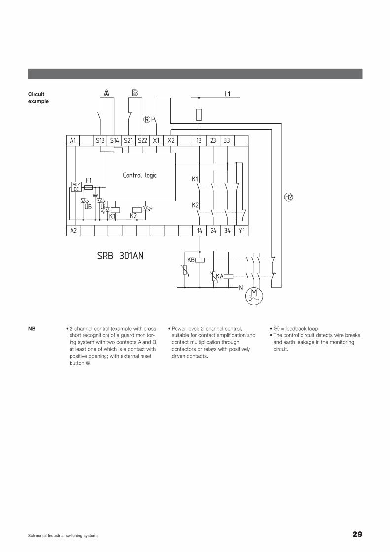
Circuitexample
SRB 301AN
L1
K1
K2
K1 K2
34 Y1
23
24
13S22S21S14S13A1 XX 21 33
14A2
F1AC/DC
UiUB
R
H2
M3
KA
N
KB
Control logic
• 2-channel control (example with cross-short recognition) of a guard monitor-ing system with two contacts A and B,at least one of which is a contact withpositive opening; with external resetbutton ®
NB • S = feedback loop• The control circuit detects wire breaks
and earth leakage in the monitoringcircuit.
• Power level: 2-channel control, suitable for contact amplification andcontact multiplication through contactors or relays with positively driven contacts.
30 Schmersal Industrial switching systems
Enabling paths 2 NO/1 NO /1 NC
UB
Ui
K1
K2
K3/4
37 23 13 Y1X1
X3 S22 S21 A238 24 14 X2
S12 S11 A1
PROTECTSRB 211ST
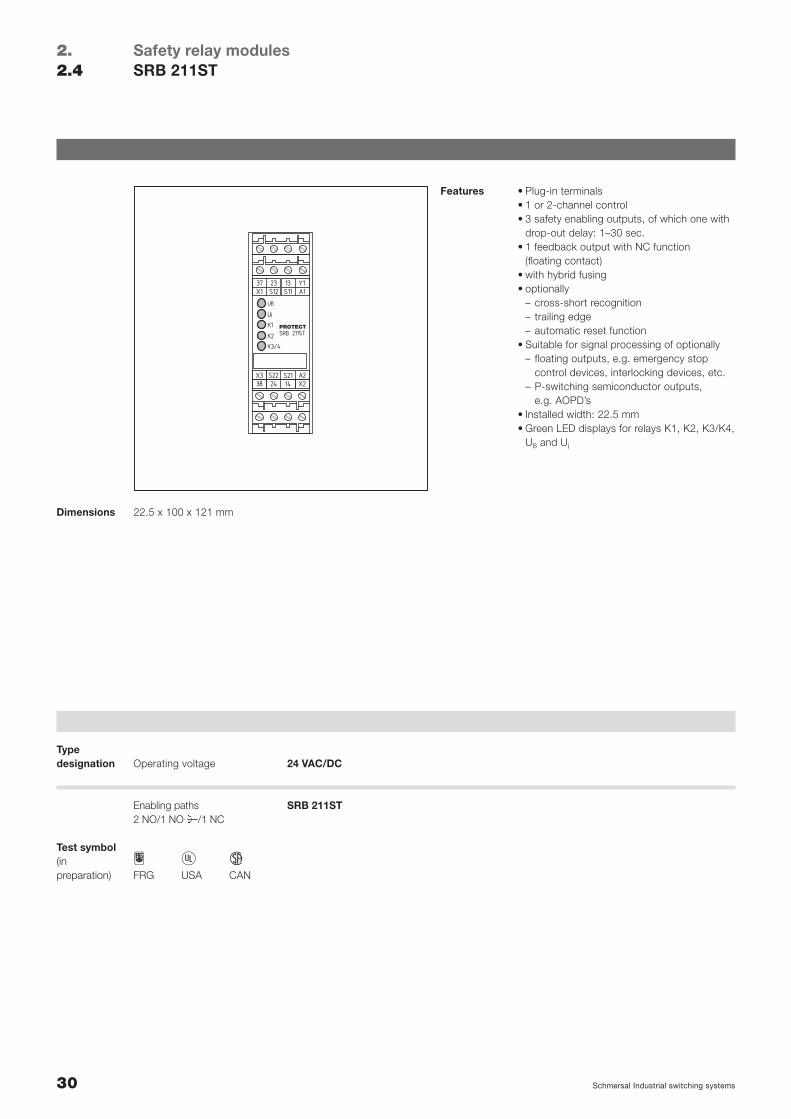
Safety relay modulesSRB 211ST
2.2.4
Features • Plug-in terminals• 1 or 2-channel control• 3 safety enabling outputs, of which one with
drop-out delay: 1–30 sec.• 1 feedback output with NC function
(floating contact)• with hybrid fusing• optionally
– cross-short recognition– trailing edge– automatic reset function
• Suitable for signal processing of optionally– floating outputs, e.g. emergency stop
control devices, interlocking devices, etc.– P-switching semiconductor outputs,
e.g. AOPD’s• Installed width: 22.5 mm• Green LED displays for relays K1, K2, K3/K4,
UB and Ui
22.5 x 100 x 121 mmDimensions
H C DFRG USA CAN
Test symbol(inpreparation)
24 VAC/DC
SRB 211ST
Operating voltageTypedesignation
31Schmersal Industrial switching systems
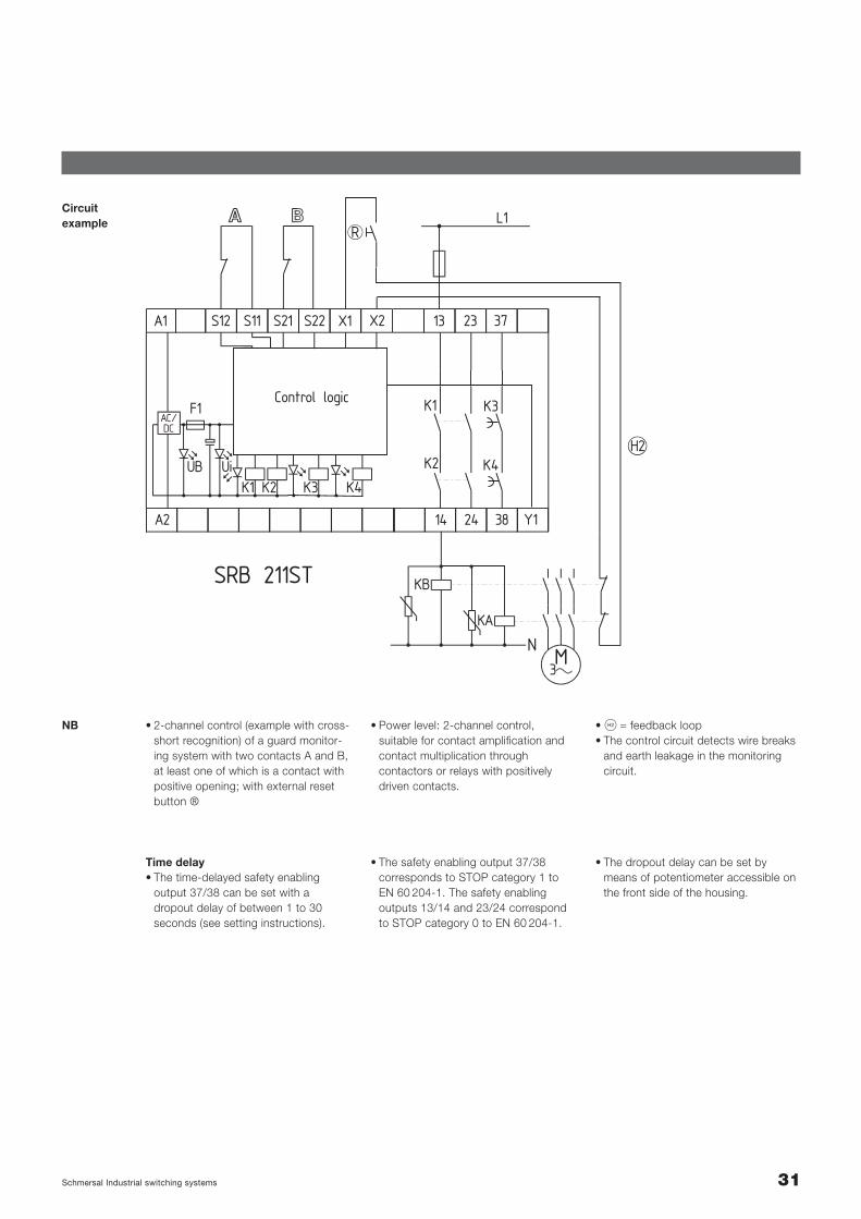
Circuit example
SRB 211ST
L1
K1 K3
K4K2
K1 K3K2 K4
38 Y1
23
24
13S22S21S11S12A1 XX 21 37
14A2
F1AC/DC
UiUB
R
H2
M3
KA
N
KB
Control logic
• 2-channel control (example with cross-short recognition) of a guard monitor-ing system with two contacts A and B,at least one of which is a contact withpositive opening; with external resetbutton ®
NB • S = feedback loop• The control circuit detects wire breaks
and earth leakage in the monitoringcircuit.
• Power level: 2-channel control, suitable for contact amplification andcontact multiplication through contactors or relays with positively driven contacts.
Time delay• The time-delayed safety enabling
output 37/38 can be set with adropout delay of between 1 to 30seconds (see setting instructions).
• The safety enabling output 37/38 corresponds to STOP category 1 toEN 60 204-1. The safety enabling outputs 13/14 and 23/24 correspondto STOP category 0 to EN 60 204-1.
• The dropout delay can be set bymeans of potentiometer accessible onthe front side of the housing.
32 Schmersal Industrial switching systems
Safety relay modulesTechnical data
2.2.5
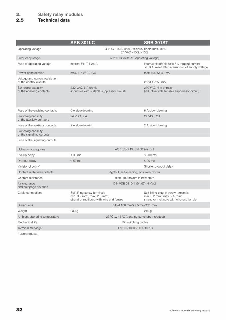
SRB 301LC SRB 301STOperating voltage 24 VDC –15%/+20%, residual ripple max. 10%
24 VAC –15%/+10%
Frequency range 50/60 Hz (with AC operating voltage)
Fuse of operating voltage internal F1: T 1.25 A internal electronic fuse F1, tripping current> 0.6 A, reset after interruption of supply voltage
Power consumption max. 1.7 W, 1.9 VA max. 2.4 W; 3.8 VA
Voltage and current restrictionof the control circuits 26 VDC/250 mA
Switching capacity 230 VAC, 6 A ohmic 230 VAC, 6 A ohmschof the enabling contacts (inductive with suitable suppressor circuit) (inductive with suitable suppressor circuit)
Fuse of the enabling contacts 6 A slow-blowing 6 A slow-blowing
Switching capacity 24 VDC, 2 A 24 VDC, 2 Aof the auxiliary contacts
Fuse of the auxiliary contacts 2 A slow-blowing 2 A slow-blowing
Switching capacityof the signalling outputs
Fuse of the signalling outputs
Utilisation categories AC 15/DC 13: EN 60 947-5-1
Pickup delay ≤ 30 ms ≤ 200 ms
Dropout delay ≤ 50 ms ≤ 20 ms
Varistor circuitry* Shorter dropout delay
Contact materials/contacts AgSnO, self-cleaning, positively driven
Contact resistance max. 100 mOhm in new state
Air clearance DIN VDE 0110-1 (04.97), 4 kV/2and creepage distance
Cable connections Self-lifting screw terminals Self-lifting plug-in screw terminalsmin. 0.2 mm2, max. 2.5 mm2, min. 0.2 mm2, max. 2.5 mm2,strand or multicore with wire end ferrule strand or multicore with wire end ferrule
Dimensions h/b/d 100 mm/22.5 mm/121 mm
Weight 230 g 240 g
Ambient operating temperature –25 °C ... 45 °C (derating curve upon request)
Mechanical life 107 switching cycles
Terminal markings DIN EN 50 005/DIN 50 013
* upon request
33Schmersal Industrial switching systems
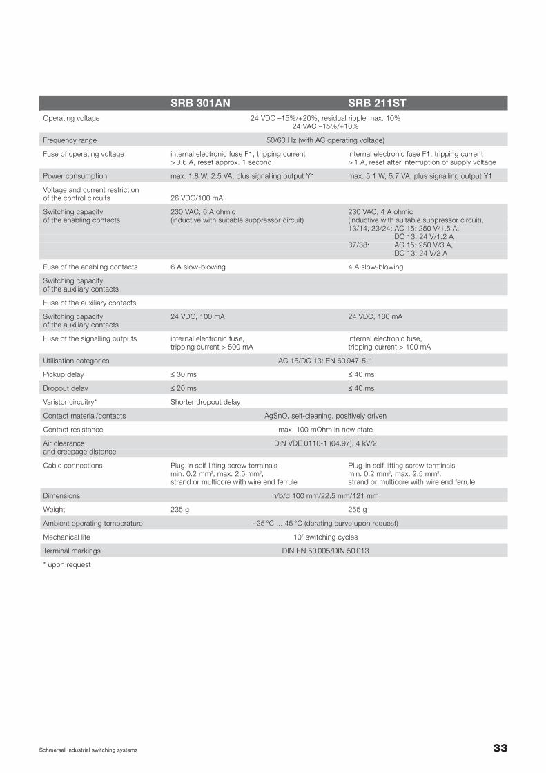
SRB 301AN SRB 211STOperating voltage 24 VDC –15%/+20%, residual ripple max. 10%
24 VAC –15%/+10%
Frequency range 50/60 Hz (with AC operating voltage)
Fuse of operating voltage internal electronic fuse F1, tripping current internal electronic fuse F1, tripping current> 0.6 A, reset approx. 1 second > 1 A, reset after interruption of supply voltage
Power consumption max. 1.8 W, 2.5 VA, plus signalling output Y1 max. 5.1 W, 5.7 VA, plus signalling output Y1
Voltage and current restrictionof the control circuits 26 VDC/100 mA
Switching capacity 230 VAC, 6 A ohmic 230 VAC, 4 A ohmicof the enabling contacts (inductive with suitable suppressor circuit) (inductive with suitable suppressor circuit),
13/14, 23/24: AC 15: 250 V/1.5 A, DC 13: 24 V/1.2 A
37/38: AC 15: 250 V/3 A, DC 13: 24 V/2 A
Fuse of the enabling contacts 6 A slow-blowing 4 A slow-blowing
Switching capacityof the auxiliary contacts
Fuse of the auxiliary contacts
Switching capacity 24 VDC, 100 mA 24 VDC, 100 mAof the auxiliary contacts
Fuse of the signalling outputs internal electronic fuse, internal electronic fuse,tripping current > 500 mA tripping current > 100 mA
Utilisation categories AC 15/DC 13: EN 60 947-5-1
Pickup delay ≤ 30 ms ≤ 40 ms
Dropout delay ≤ 20 ms ≤ 40 ms
Varistor circuitry* Shorter dropout delay
Contact material/contacts AgSnO, self-cleaning, positively driven
Contact resistance max. 100 mOhm in new state
Air clearance DIN VDE 0110-1 (04.97), 4 kV/2and creepage distance
Cable connections Plug-in self-lifting screw terminals Plug-in self-lifting screw terminalsmin. 0.2 mm2, max. 2.5 mm2, min. 0.2 mm2, max. 2.5 mm2, strand or multicore with wire end ferrule strand or multicore with wire end ferrule
Dimensions h/b/d 100 mm/22.5 mm/121 mm
Weight 235 g 255 g
Ambient operating temperature –25 °C ... 45 °C (derating curve upon request)
Mechanical life 107 switching cycles
Terminal markings DIN EN 50 005/DIN 50 013
* upon request

34 Schmersal Industrial switching systems
Notes
14
13 KA
KA KB
KB
L1
N
S11 S22S12S11
K
K
A
B
R
X2S12
35Schmersal Industrial switching systems
Safety relay modulesSelection of applications
2.2.6
1.4 Selection of applications
Start configurationExternal reset button . . . . . . . . . . . . . . . . . . . . . . . . . . . . . . . . . . . . . . . . . . . . . . . . Page 36Automatic . . . . . . . . . . . . . . . . . . . . . . . . . . . . . . . . . . . . . . . . . . . . . . . . . . . . . . . . Page 36
Sensor configurationEMERGENCY-STOP . . . . . . . . . . . . . . . . . . . . . . . . . . . . . . . . . . . . . . . . . . . . . . . . Page 37Guard . . . . . . . . . . . . . . . . . . . . . . . . . . . . . . . . . . . . . . . . . . . . . . . . . . . . . . . . . . Page 38P-switching semiconductor . . . . . . . . . . . . . . . . . . . . . . . . . . . . . . . . . . . . . . . . . . . Page 39Magnet safety sensors . . . . . . . . . . . . . . . . . . . . . . . . . . . . . . . . . . . . . . . . . . . . . . . Page 39
Actuator configuration/contact multiplication (KV)Single-channel . . . . . . . . . . . . . . . . . . . . . . . . . . . . . . . . . . . . . . . . . . . . . . . . . . . . Page 40Dual-channel . . . . . . . . . . . . . . . . . . . . . . . . . . . . . . . . . . . . . . . . . . . . . . . . . . . . . Page 40Diversitary . . . . . . . . . . . . . . . . . . . . . . . . . . . . . . . . . . . . . . . . . . . . . . . . . . . . . . . Page 40
The following selection of applicationsis intended to provide users with assistance on which functionalitiesPROTECT SRBs offer.
The circuit examples are suggestionswhich do not (cannot), however, re-lease the user from his own responsi-bility to check the circuitry carefully interms of its suitability for the individualcase.
SRB 301ST
L1
K2
K3
K1 K2
11
1 34
41
42
23
24
3S22 S21S11S11S 2A1 X2 X3 33
4A2
F1AC/DC
UiUB
Control circuit
R
H2
M3
KA
N
KB
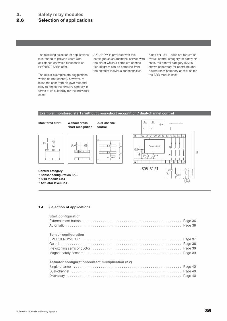
Example: monitored start / without cross-short recognition / dual-channel control
Monitored start Without cross-short recognition
Dual-channelcontrol
Control category:• Sensor configuration SK3• SRB module SK4• Actuator level SK4
A CD ROM is provided with this catalogue as an additional service withthe aid of which a complete connec-tion diagram can be compiled fromthe different individual functionalities.
Since EN 954-1 does not require anoverall control category for safety cir-cuits, the control category (SK) isshown separately for upstream anddownstream periphery as well as forthe SRB module itself.
36 Schmersal Industrial switching systems
Start configuration
Safety relay modulesSelection of applications
2.2.6
R
X2
S12
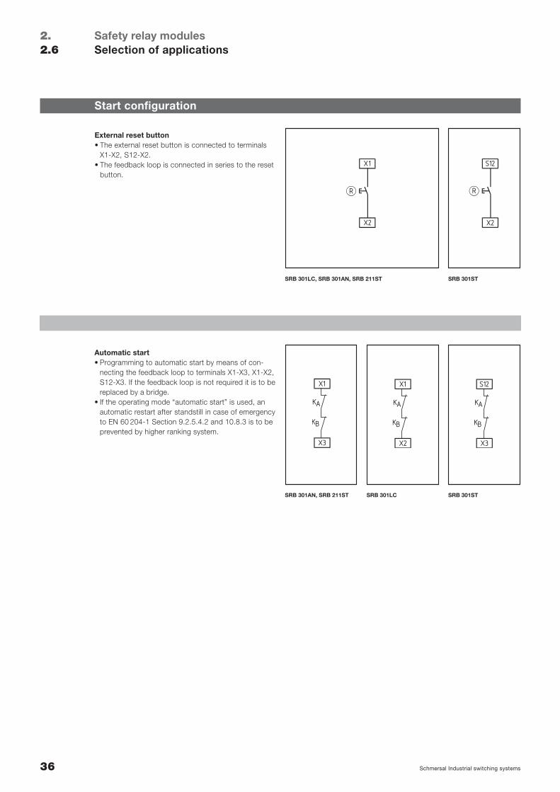
External reset button• The external reset button is connected to terminals
X1-X2, S12-X2.• The feedback loop is connected in series to the reset
button.
Automatic start• Programming to automatic start by means of con-
necting the feedback loop to terminals X1-X3, X1-X2,S12-X3. If the feedback loop is not required it is to bereplaced by a bridge.
• If the operating mode “automatic start” is used, anautomatic restart after standstill in case of emergencyto EN 60 204-1 Section 9.2.5.4.2 and 10.8.3 is to beprevented by higher ranking system.
SRB 301AN, SRB 211ST SRB 301LC
SRB 301LC, SRB 301AN, SRB 211ST SRB 301ST
SRB 301ST
R
X2
X1
K
K
A
B
X3
S12
K
K
A
B
X2
X1
K
K
A
B
X3
X1
37Schmersal Industrial switching systems
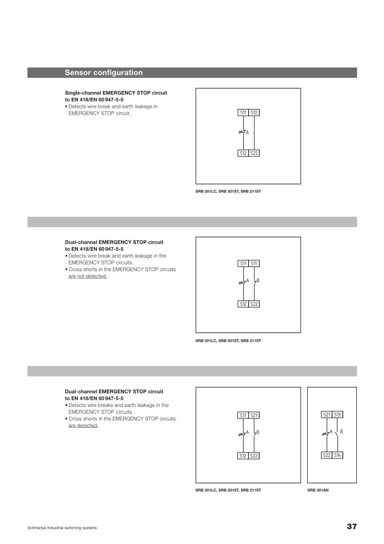
Sensor configuration
Single-channel EMERGENCY STOP circuit to EN 418/EN 60 947-5-5• Detects wire break and earth leakage in
EMERGENCY STOP circuit.
Dual-channel EMERGENCY STOP circuit to EN 418/EN 60 947-5-5• Detects wire break and earth leakage in the
EMERGENCY STOP circuits.• Cross shorts in the EMERGENCY STOP circuits
are not detected.
Dual-channel EMERGENCY STOP circuit to EN 418/EN 60 947-5-5• Detects wire breaks and earth leakage in the
EMERGENCY STOP circuits.• Cross shorts in the EMERGENCY STOP circuits
are detected.
SRB 301LC, SRB 301ST, SRB 211ST
SRB 301LC, SRB 301ST, SRB 211ST
SRB 301LC, SRB 301ST, SRB 211ST SRB 301AN
S12
S11
S22
S12
A
S12
S11
S22
S11
A B
S22
S21
S14
S13
A B
S12
S11
S22
S21
A B
38 Schmersal Industrial switching systems
Safety relay modulesSelection of applications
2.2.6
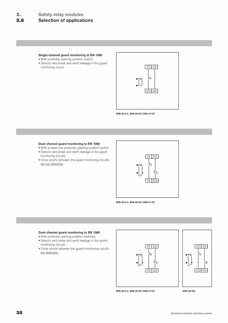
Single-channel guard monitoring to EN 1088• With positively opening position switch.• Detects wire break and earth leakage in the guard
monitoring circuit.
Dual-channel guard monitoring to EN 1088• With at least one positively opening position switch.• Detects wire break and earth leakage in the guard
monitoring circuits.• Cross shorts between the guard monitoring circuits
are not detected.
Dual-channel guard monitoring to EN 1088• With positively opening position switches.• Detects wire break and earth leakage in the guard
monitoring circuits.• Cross shorts between the guard monitoring circuits
are detected.
SRB 301LC, SRB 301ST, SRB 211ST
SRB 301LC, SRB 301ST, SRB 211ST
SRB 301LC, SRB 301ST, SRB 211ST SRB 301AN
S12
S11
S22
S12
A
S12
S11
S22
S11
A
B
S22
S21
S14
S13
A
B
S12
S11
S22
S21
A
B
39Schmersal Industrial switching systems
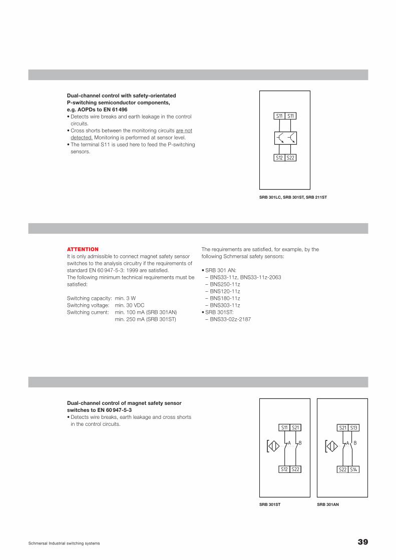
Dual-channel control with safety-orientated P-switching semiconductor components, e.g. AOPDs to EN 61496• Detects wire breaks and earth leakage in the control
circuits.• Cross shorts between the monitoring circuits are not
detected. Monitoring is performed at sensor level.• The terminal S11 is used here to feed the P-switching
sensors.
ATTENTIONIt is only admissible to connect magnet safety sensorswitches to the analysis circuitry if the requirements ofstandard EN 60 947-5-3: 1999 are satisfied.The following minimum technical requirements must besatisfied:
Switching capacity: min. 3 WSwitching voltage: min. 30 VDCSwitching current: min. 100 mA (SRB 301AN)
min. 250 mA (SRB 301ST)
Dual-channel control of magnet safety sensorswitches to EN 60 947-5-3• Detects wire breaks, earth leakage and cross shorts
in the control circuits.
SRB 301LC, SRB 301ST, SRB 211ST
The requirements are satisfied, for example, by the following Schmersal safety sensors:
• SRB 301 AN:– BNS33-11z, BNS33-11z-2063– BNS250-11z– BNS120-11z– BNS180-11z– BNS303-11z
• SRB 301ST:– BNS33-02z-2187
SRB 301ST SRB 301AN
S12
S11
S22
S11
S12
S11
S22
S21
A B
S22
S21
S14
S13
A B
40 Schmersal Industrial switching systems
Actuator configuration
Safety relay modulesSelection of applications
2.2.6
KA KC
X1 X2
14
13
38
37
KA KC
KAL1
N
*KC
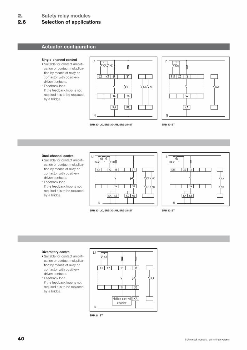
Single-channel control• Suitable for contact amplifi-
cation or contact multiplica-tion by means of relay orcontactor with positively driven contacts.
* Feedback loopIf the feedback loop is notrequired it is to be replacedby a bridge.
Dual-channel control• Suitable for contact amplifi-
cation or contact multiplica-tion by means of relay orcontactor with positively driven contacts.
* Feedback loopIf the feedback loop is notrequired it is to be replacedby a bridge.
Diversitary control • Suitable for contact amplifi-
cation or contact multiplica-tion by means of relay orcontactor with positively driven contacts.
* Feedback loopIf the feedback loop is notrequired it is to be replacedby a bridge.
SRB 301LC, SRB 301AN, SRB 211ST SRB 301ST
SRB 301LC, SRB 301AN, SRB 211ST SRB 301ST
SRB 211ST
KA
S12 X2
14
13
KA
KAL1
N
*
KB KD
X1 X2
14
13
38
37
KA KC
KB KD
KAKB KC
L1
N
* KD
KA KC KB
S12 X2
14
13
KA
KB
KAKB
L1
N
*
KA
Motion controlenabler
KA
X1 X2
14
13
38
37
KA
KAL1
N
*
41Schmersal Industrial switching systems
Terminal designation
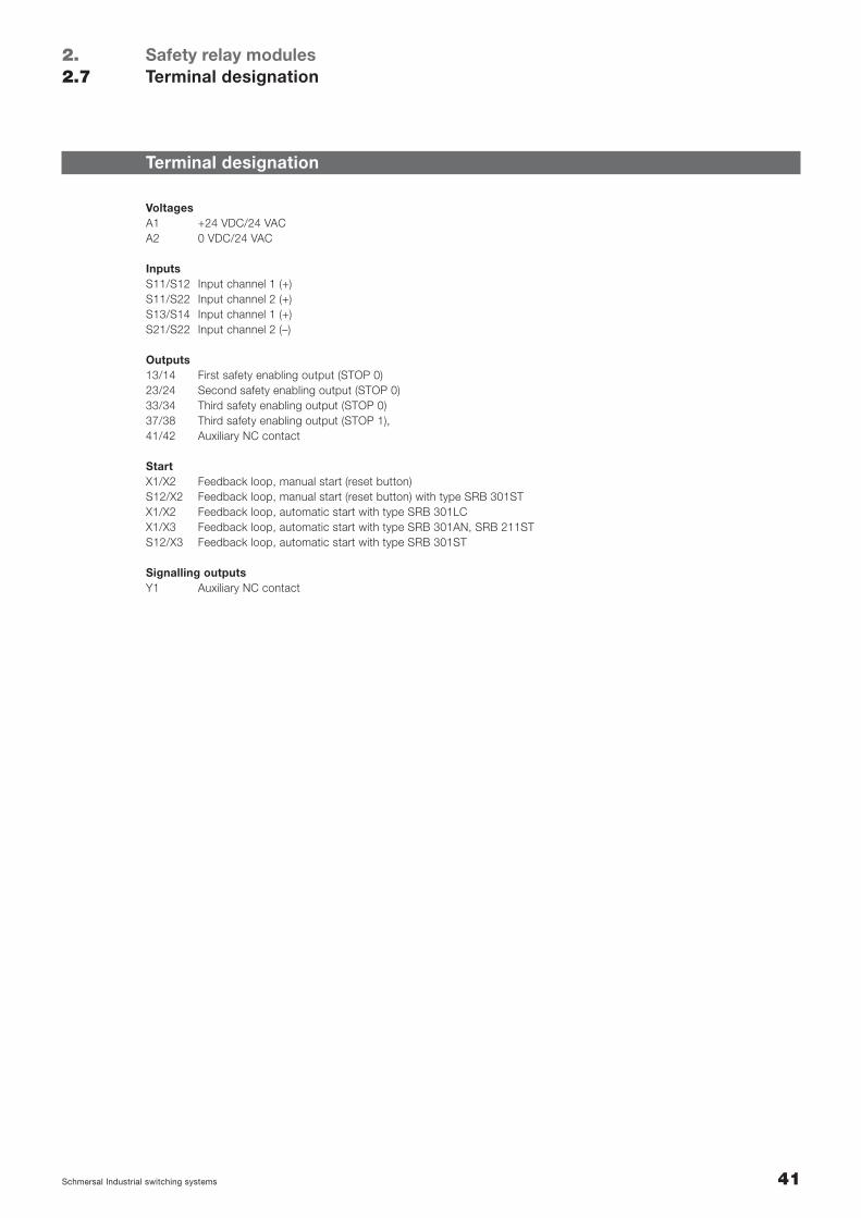
VoltagesA1 +24 VDC/24 VACA2 0 VDC/24 VAC
InputsS11/S12 Input channel 1 (+)S11/S22 Input channel 2 (+)S13/S14 Input channel 1 (+)S21/S22 Input channel 2 (–)
Outputs13/14 First safety enabling output (STOP 0)23/24 Second safety enabling output (STOP 0)33/34 Third safety enabling output (STOP 0)37/38 Third safety enabling output (STOP 1),41/42 Auxiliary NC contact
StartX1/X2 Feedback loop, manual start (reset button)S12/X2 Feedback loop, manual start (reset button) with type SRB 301STX1/X2 Feedback loop, automatic start with type SRB 301LCX1/X3 Feedback loop, automatic start with type SRB 301AN, SRB 211STS12/X3 Feedback loop, automatic start with type SRB 301ST
Signalling outputsY1 Auxiliary NC contact
Safety relay modulesTerminal designation
2.2.7

42 Schmersal Industrial switching systems
Notes
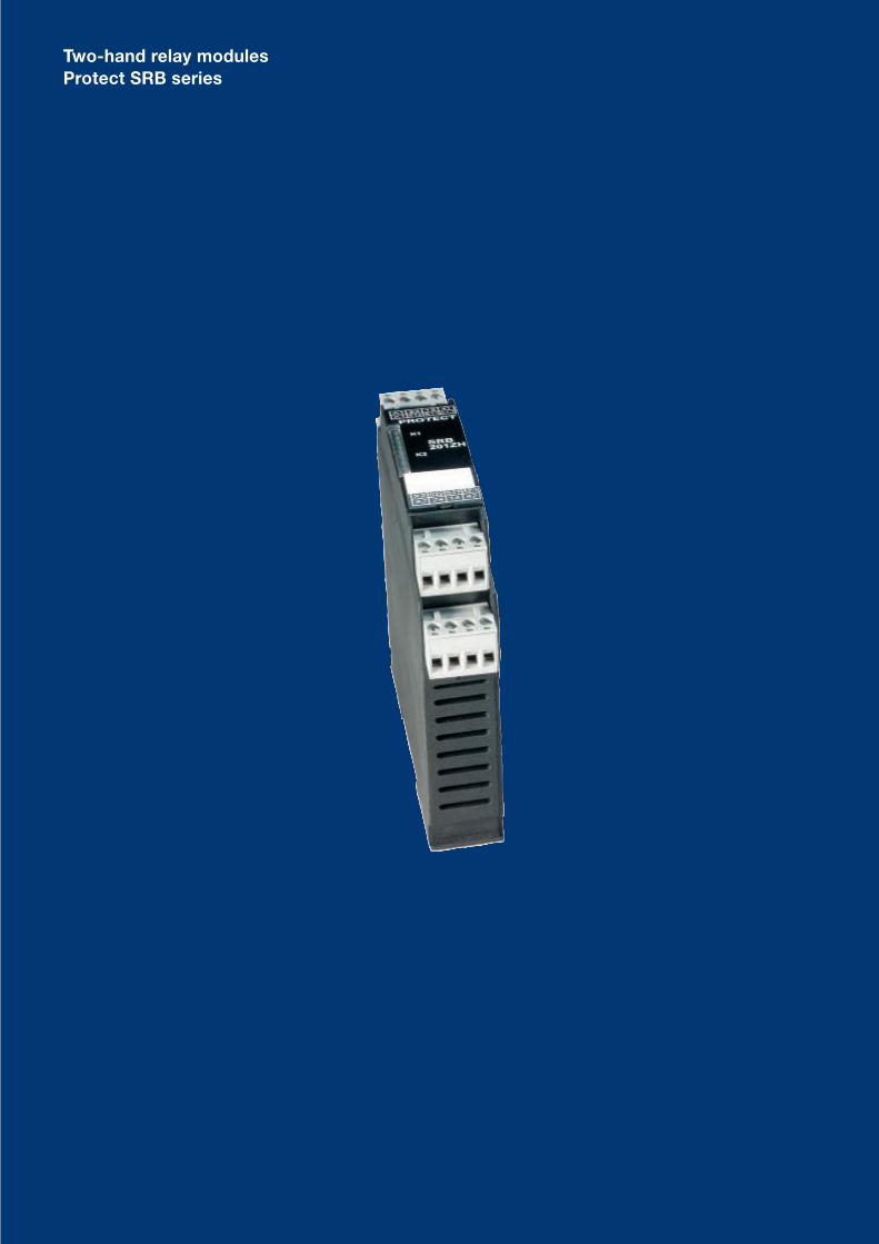
Two-hand relay modulesProtect SRB series
44 Schmersal Industrial switching systems
Enabling paths 2 NO/1 NC
K1
K2
A1 23 13 31X1
X2 S22 S21 A2.1A2 24 14 32
S12 S11 A1.1
PROTECTSRB 201ZH
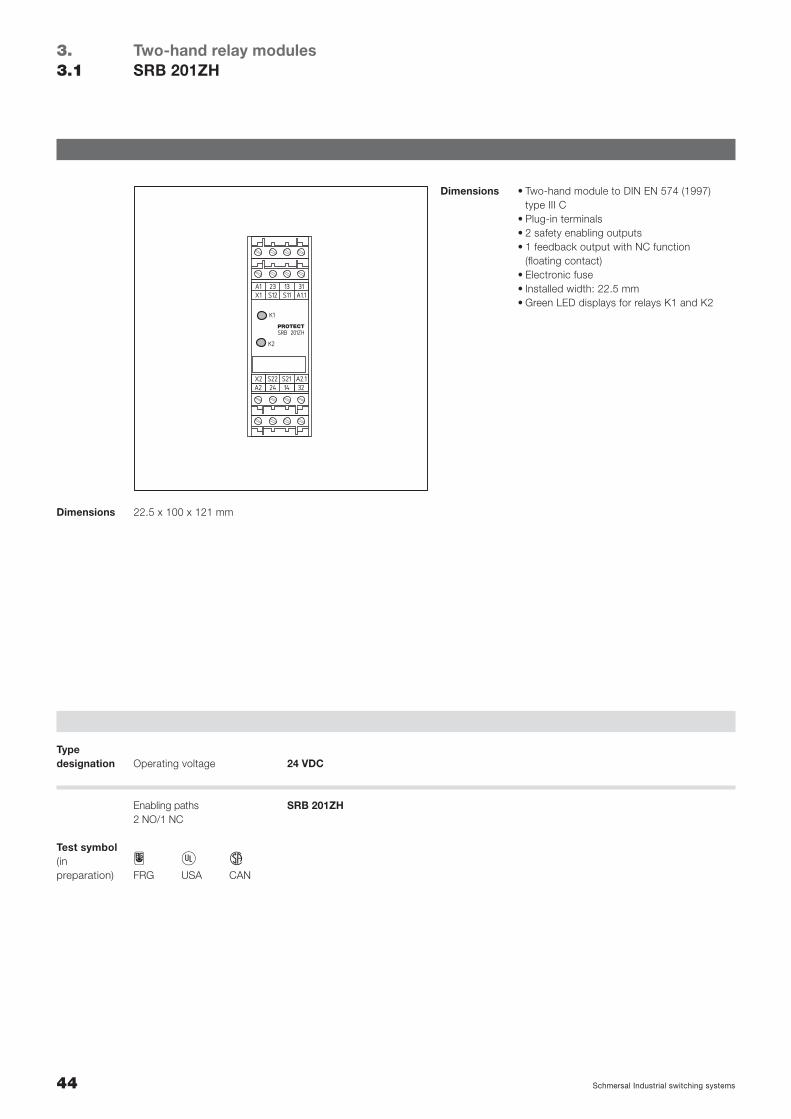
Two-hand relay modulesSRB 201ZH
3.3.1
Dimensions • Two-hand module to DIN EN 574 (1997) type III C
• Plug-in terminals• 2 safety enabling outputs• 1 feedback output with NC function
(floating contact)• Electronic fuse• Installed width: 22.5 mm• Green LED displays for relays K1 and K2
22.5 x 100 x 121 mmDimensions
H C DFRG USA CAN
Test symbol(inpreparation)
24 VDC
SRB 201ZH
Operating voltageTypedesignation
45Schmersal Industrial switching systems
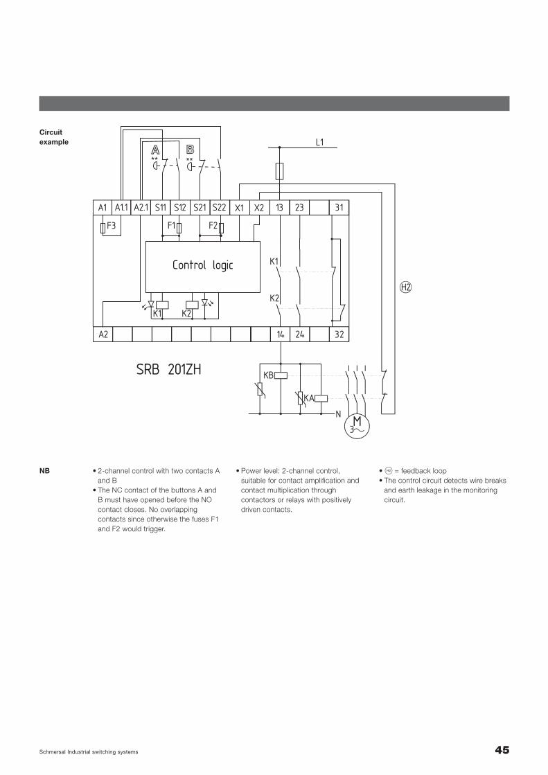
Circuitexample
SRB 201ZH
L1
K1
F1F3 F2
K2
K1 K2
312313S21 S22S12S11A2.1A1.1A1 X1 X2
322414A2
Control logic
H2
M3
KA
N
KB
** **
• 2-channel control with two contacts Aand B
• The NC contact of the buttons A andB must have opened before the NOcontact closes. No overlapping contacts since otherwise the fuses F1and F2 would trigger.
NB • S = feedback loop• The control circuit detects wire breaks
and earth leakage in the monitoringcircuit.
• Power level: 2-channel control, suitable for contact amplification andcontact multiplication through contactors or relays with positively driven contacts.
46 Schmersal Industrial switching systems
Two-hand relay modulesTechnical data
3.3.2
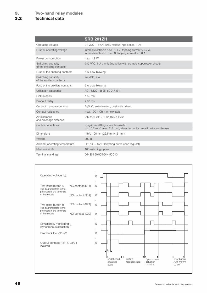
SRB 201ZHOperating voltage 24 VDC –15%/+10%, residual ripple max. 10%
Fuse of operating voltage internal electronic fuse F1, F2, tripping current > 0.2 A,internal electronic fuse F3, tripping current > 0.6 A
Power consumption max. 1.2 W
Switching capacity 230 VAC, 6 A ohmic (inductive with suitable suppressor circuit)of the enabling contacts
Fuse of the enabling contacts 6 A slow-blowing
Switching capacity 24 VDC, 2 Aof the auxiliary contacts
Fuse of the auxiliary contacts 2 A slow-blowing
Utilisation categories AC 15/DC 13: EN 60 947-5-1
Pickup delay ≤ 50 ms
Dropout delay ≤ 30 ms
Contact material/contacts AgSnO, self-cleaning, positively driven
Contact resistance max. 100 mOhm in new state
Air clearance DIN VDE 0110-1 (04.97), 4 kV/2and creepage distance
Cable connections Plug-in self-lifting screw terminalsmin. 0.2 mm2, max. 2.5 mm2, strand or multicore with wire end ferrule
Dimensions h/b/d 100 mm/22.5 mm/121 mm
Weight 200 g
Ambient operating temperature –25 °C ... 45 °C (derating curve upon request)
Mechanical life 107 switching cycles
Terminal markings DIN EN 50 005/DIN 50 013
Output contacts 13/14, 23/24isolated
Feedback loop X1-X2
Simultaneity monitoring t(synchronous actuation)
Two-hand button AThe diagram refers to the potentials at the terminalsof the module
The diagram refers to the potentials at the terminalsof the module
Two-hand button B
Operating voltage U
1
1
1
1
0
0
0
0
10
10
10
10
t
NC contact (S11)
NC contact (S21)
NO contact (S12)
NO contact (S22)
S
S
Error buttonA, B before U on
Synchronousactuationt > 0.5 s
undisturbed operatingcycle
Error in feedback loop
B
B
47Schmersal Industrial switching systems
Start/sensor configuration
Two-hand relay modulesSelection of applications
3.3.3
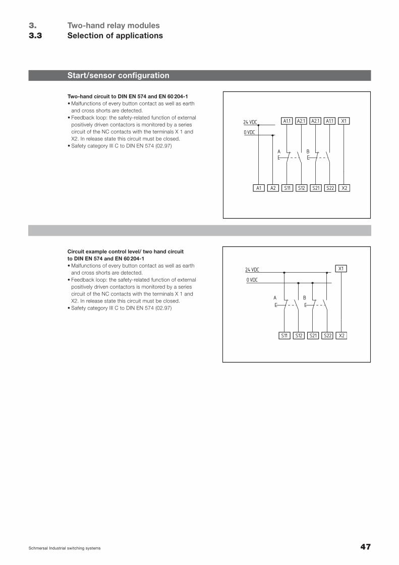
A1.1 A2.1 A2.1 A1.1 X1
A2A1 S11 S12 S21 S22 X2
A
0 VDC
24 VDC
B
Two-hand circuit to DIN EN 574 and EN 60 204-1• Malfunctions of every button contact as well as earth
and cross shorts are detected.• Feedback loop: the safety-related function of external
positively driven contactors is monitored by a seriescircuit of the NC contacts with the terminals X 1 andX2. In release state this circuit must be closed.
• Safety category III C to DIN EN 574 (02.97)
X1
S11 S12 S21 S22 X2
A
0 VDC
24 VDC
B
Circuit example control level/ two hand circuit to DIN EN 574 and EN 60 204-1• Malfunctions of every button contact as well as earth
and cross shorts are detected.• Feedback loop: the safety-related function of external
positively driven contactors is monitored by a seriescircuit of the NC contacts with the terminals X 1 andX2. In release state this circuit must be closed.
• Safety category III C to DIN EN 574 (02.97)
48 Schmersal Industrial switching systems
Actuator configuration
Two-hand relay modulesSelection of applications
3.3.3
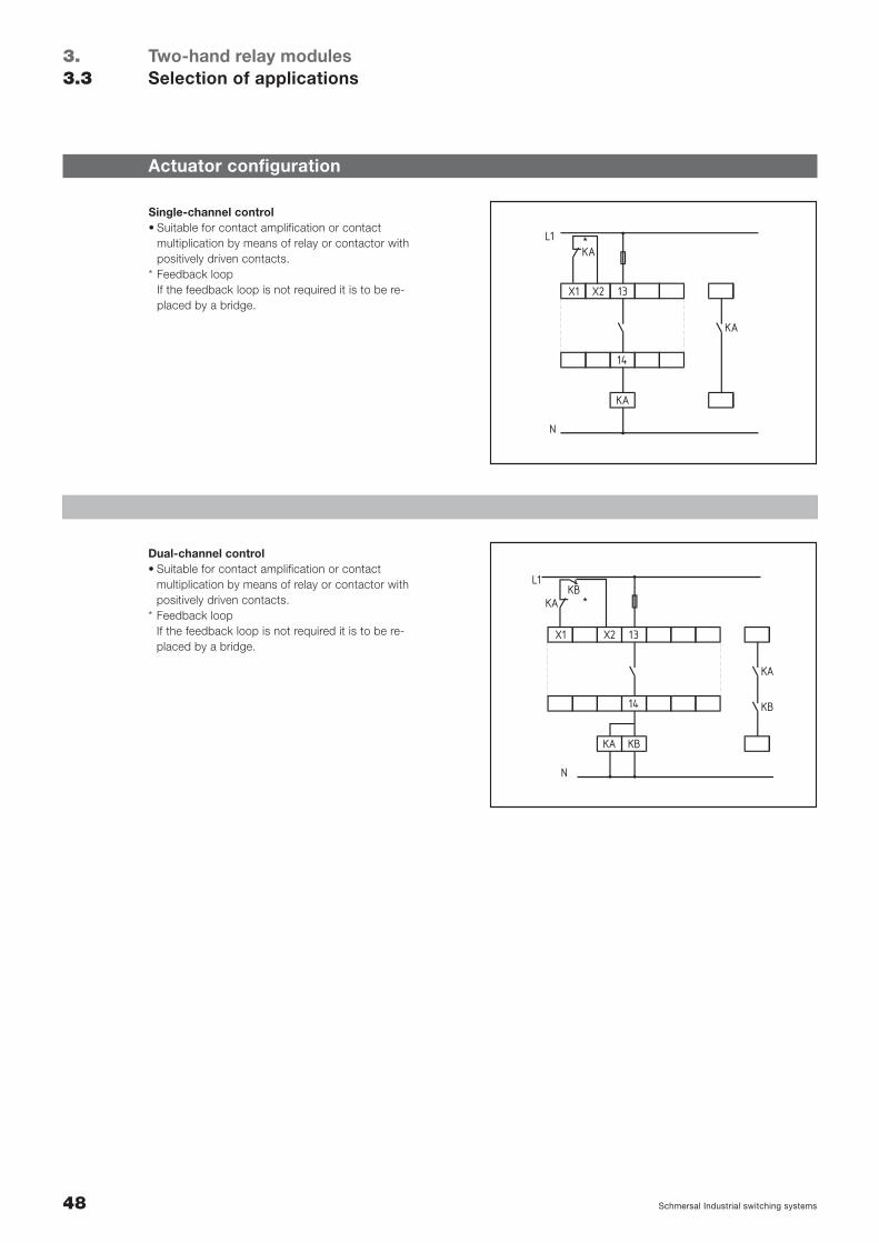
KA
X1 X2
14
13
KA
KAL1
N
*
Single-channel control• Suitable for contact amplification or contact
multiplication by means of relay or contactor withpositively driven contacts.
* Feedback loopIf the feedback loop is not required it is to be re-placed by a bridge.
KB
X1 X2
14
13
KA
KB
KAKB
L1
N
*
KA
Dual-channel control• Suitable for contact amplification or contact
multiplication by means of relay or contactor withpositively driven contacts.
* Feedback loopIf the feedback loop is not required it is to be re-placed by a bridge.
49Schmersal Industrial switching systems
Terminal designation
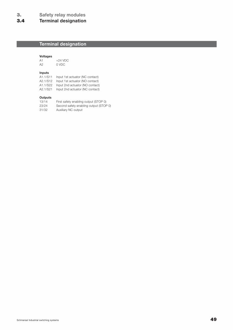
VoltagesA1 +24 VDCA2 0 VDC
InputsA1.1/S11 Input 1st actuator (NC contact)A2.1/S12 Input 1st actuator (NO contact)A1.1/S22 Input 2nd actuator (NO contact)A2.1/S21 Input 2nd actuator (NC contact)
Outputs13/14 First safety enabling output (STOP 0)23/24 Second safety enabling output (STOP 0)31/32 Auxiliary NC output
Safety relay modulesTerminal designation
3.3.4

50 Schmersal Industrial switching systems
Notes
51Schmersal Industrial switching systems
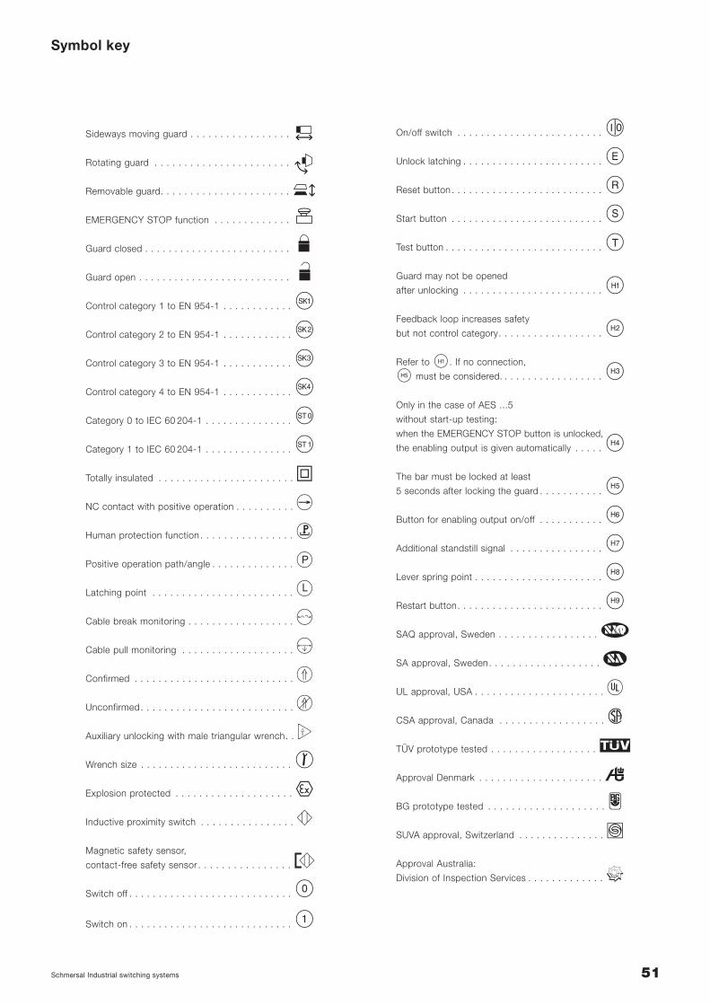
Symbol key
On/off switch . . . . . . . . . . . . . . . . . . . . . . . . . c
Unlock latching . . . . . . . . . . . . . . . . . . . . . . . . b
Reset button . . . . . . . . . . . . . . . . . . . . . . . . . . J
Start button . . . . . . . . . . . . . . . . . . . . . . . . . . H
Test button . . . . . . . . . . . . . . . . . . . . . . . . . . . I
Guard may not be opened
after unlocking . . . . . . . . . . . . . . . . . . . . . . . . R
Feedback loop increases safety
but not control category. . . . . . . . . . . . . . . . . . S
Refer to R. If no connection,
V must be considered. . . . . . . . . . . . . . . . . . T
Only in the case of AES ...5
without start-up testing:
when the EMERGENCY STOP button is unlocked,
the enabling output is given automatically . . . . . U
The bar must be locked at least
5 seconds after locking the guard . . . . . . . . . . . V
Button for enabling output on/off . . . . . . . . . . . W
Additional standstill signal . . . . . . . . . . . . . . . . X
Lever spring point . . . . . . . . . . . . . . . . . . . . . . Y
Restart button. . . . . . . . . . . . . . . . . . . . . . . . . Z
SAQ approval, Sweden . . . . . . . . . . . . . . . . . ZSA approval, Sweden. . . . . . . . . . . . . . . . . . . EUL approval, USA . . . . . . . . . . . . . . . . . . . . . . CCSA approval, Canada . . . . . . . . . . . . . . . . . . DTÜV prototype tested . . . . . . . . . . . . . . . . . . F
Approval Denmark . . . . . . . . . . . . . . . . . . . . . G
BG prototype tested . . . . . . . . . . . . . . . . . . . . HSUVA approval, Switzerland . . . . . . . . . . . . . . . IApproval Australia:
Division of Inspection Services . . . . . . . . . . . . . J
Sideways moving guard . . . . . . . . . . . . . . . . .
Rotating guard . . . . . . . . . . . . . . . . . . . . . . .
Removable guard. . . . . . . . . . . . . . . . . . . . . .
EMERGENCY STOP function . . . . . . . . . . . . .
Guard closed . . . . . . . . . . . . . . . . . . . . . . . . .
Guard open . . . . . . . . . . . . . . . . . . . . . . . . . .
Control category 1 to EN 954-1 . . . . . . . . . . . . K
Control category 2 to EN 954-1 . . . . . . . . . . . . L
Control category 3 to EN 954-1 . . . . . . . . . . . . M
Control category 4 to EN 954-1 . . . . . . . . . . . . N
Category 0 to IEC 60 204-1 . . . . . . . . . . . . . . . d
Category 1 to IEC 60 204-1 . . . . . . . . . . . . . . . e
Totally insulated . . . . . . . . . . . . . . . . . . . . . . . XNC contact with positive operation . . . . . . . . . . AHuman protection function . . . . . . . . . . . . . . . . BPositive operation path/angle . . . . . . . . . . . . . . TLatching point . . . . . . . . . . . . . . . . . . . . . . . . UCable break monitoring . . . . . . . . . . . . . . . . . . VCable pull monitoring . . . . . . . . . . . . . . . . . . . WConfirmed . . . . . . . . . . . . . . . . . . . . . . . . . . . PUnconfirmed. . . . . . . . . . . . . . . . . . . . . . . . . . QAuxiliary unlocking with male triangular wrench. . OWrench size . . . . . . . . . . . . . . . . . . . . . . . . . . i
Explosion protected . . . . . . . . . . . . . . . . . . . . LInductive proximity switch . . . . . . . . . . . . . . . . RMagnetic safety sensor,
contact-free safety sensor . . . . . . . . . . . . . . . . SSwitch off . . . . . . . . . . . . . . . . . . . . . . . . . . . . k
Switch on . . . . . . . . . . . . . . . . . . . . . . . . . . . . l
52 Schmersal Industrial switching systems
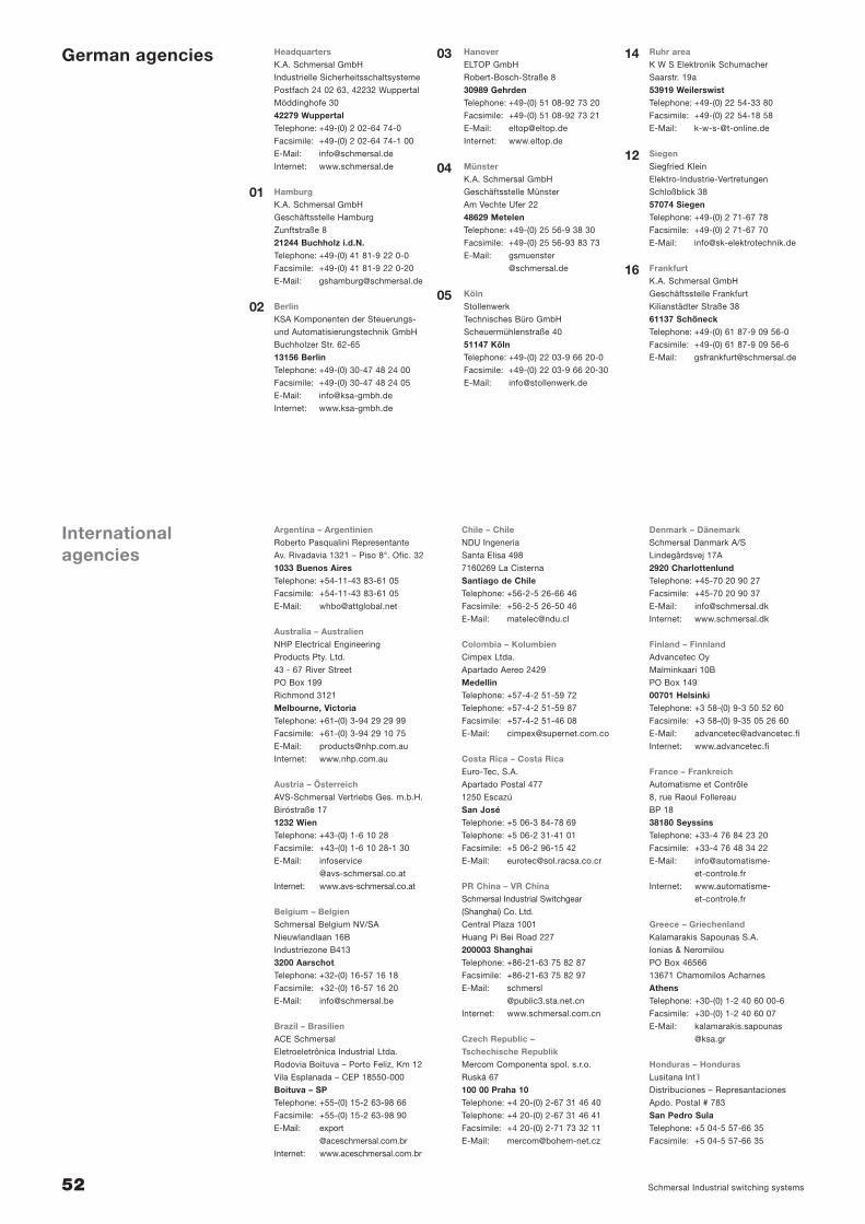
Argentina – ArgentinienRoberto Pasqualini Representante
Av. Rivadavia 1321 – Piso 8°. Ofic. 32
1033 Buenos AiresTelephone: +54-11-43 83-61 05
Facsimile: +54-11-43 83-61 05
E-Mail: [email protected]
Australia – AustralienNHP Electrical Engineering
Products Pty. Ltd.
43 - 67 River Street
PO Box 199
Richmond 3121
Melbourne, VictoriaTelephone: +61-(0) 3-94 29 29 99
Facsimile: +61-(0) 3-94 29 10 75
E-Mail: [email protected]
Internet: www.nhp.com.au
Austria – ÖsterreichAVS-Schmersal Vertriebs Ges. m.b.H.
Biróstraße 17
1232 WienTelephone: +43-(0) 1-6 10 28
Facsimile: +43-(0) 1-6 10 28-1 30
E-Mail: infoservice
@avs-schmersal.co.at
Internet: www.avs-schmersal.co.at
Belgium – BelgienSchmersal Belgium NV/SA
Nieuwlandlaan 16B
Industriezone B413
3200 AarschotTelephone: +32-(0) 16-57 16 18
Facsimile: +32-(0) 16-57 16 20
E-Mail: [email protected]
Brazil – BrasilienACE Schmersal
Eletroeletrônica Industrial Ltda.
Rodovia Boituva – Porto Feliz, Km 12
Vila Esplanada – CEP 18550-000
Boituva – SPTelephone: +55-(0) 15-2 63-98 66
Facsimile: +55-(0) 15-2 63-98 90
E-Mail: export
@aceschmersal.com.br
Internet: www.aceschmersal.com.br
Chile – ChileNDU Ingeneria
Santa Elisa 498
7160269 La Cisterna
Santiago de ChileTelephone: +56-2-5 26-66 46
Facsimile: +56-2-5 26-50 46
E-Mail: [email protected]
Colombia – KolumbienCimpex Ltda.
Apartado Aereo 2429
MedellinTelephone: +57-4-2 51-59 72
Telephone: +57-4-2 51-59 87
Facsimile: +57-4-2 51-46 08
E-Mail: [email protected]
Costa Rica – Costa RicaEuro-Tec, S.A.
Apartado Postal 477
1250 Escazú
San JoséTelephone: +5 06-3 84-78 69
Telephone: +5 06-2 31-41 01
Facsimile: +5 06-2 96-15 42
E-Mail: [email protected]
PR China – VR ChinaSchmersal Industrial Switchgear
(Shanghai) Co. Ltd.
Central Plaza 1001
Huang Pi Bei Road 227
200003 ShanghaiTelephone: +86-21-63 75 82 87
Facsimile: +86-21-63 75 82 97
E-Mail: schmersl
@public3.sta.net.cn
Internet: www.schmersal.com.cn
Czech Republic – Tschechische RepublikMercom Componenta spol. s.r.o.
Ruská 67
100 00 Praha 10Telephone: +4 20-(0) 2-67 31 46 40
Telephone: +4 20-(0) 2-67 31 46 41
Facsimile: +4 20-(0) 2-71 73 32 11
E-Mail: [email protected]
Denmark – Dänemark Schmersal Danmark A/S
Lindegårdsvej 17A
2920 CharlottenlundTelephone: +45-70 20 90 27
Facsimile: +45-70 20 90 37
E-Mail: [email protected]
Internet: www.schmersal.dk
Finland – FinnlandAdvancetec Oy
Malminkaari 10B
PO Box 149
00701 HelsinkiTelephone: +3 58-(0) 9-3 50 52 60
Facsimile: +3 58-(0) 9-35 05 26 60
E-Mail: [email protected]
Internet: www.advancetec.fi
France – FrankreichAutomatisme et Contrôle
8, rue Raoul Follereau
BP 18
38180 SeyssinsTelephone: +33-4 76 84 23 20
Facsimile: +33-4 76 48 34 22
E-Mail: info@automatisme-
et-controle.fr
Internet: www.automatisme-
et-controle.fr
Greece – GriechenlandKalamarakis Sapounas S.A.
Ionias & Neromilou
PO Box 46566
13671 Chamomilos Acharnes
AthensTelephone: +30-(0) 1-2 40 60 00-6
Facsimile: +30-(0) 1-2 40 60 07
E-Mail: kalamarakis.sapounas
@ksa.gr
Honduras – HondurasLusitana Int´I
Distribuciones – Represantaciones
Apdo. Postal # 783
San Pedro SulaTelephone: +5 04-5 57-66 35
Facsimile: +5 04-5 57-66 35
HeadquartersK.A. Schmersal GmbH
Industrielle Sicherheitsschaltsysteme
Postfach 24 02 63, 42232 Wuppertal
Möddinghofe 30
42279 WuppertalTelephone: +49-(0) 2 02-64 74-0
Facsimile: +49-(0) 2 02-64 74-1 00
E-Mail: [email protected]
Internet: www.schmersal.de
HamburgK.A. Schmersal GmbH
Geschäftsstelle Hamburg
Zunftstraße 8
21244 Buchholz i.d.N.Telephone: +49-(0) 41 81-9 22 0-0
Facsimile: +49-(0) 41 81-9 22 0-20
E-Mail: [email protected]
BerlinKSA Komponenten der Steuerungs-
und Automatisierungstechnik GmbH
Buchholzer Str. 62-65
13156 BerlinTelephone: +49-(0) 30-47 48 24 00
Facsimile: +49-(0) 30-47 48 24 05
E-Mail: [email protected]
Internet: www.ksa-gmbh.de
HanoverELTOP GmbH
Robert-Bosch-Straße 8
30989 GehrdenTelephone: +49-(0) 51 08-92 73 20
Facsimile: +49-(0) 51 08-92 73 21
E-Mail: [email protected]
Internet: www.eltop.de
MünsterK.A. Schmersal GmbH
Geschäftsstelle Münster
Am Vechte Ufer 22
48629 MetelenTelephone: +49-(0) 25 56-9 38 30
Facsimile: +49-(0) 25 56-93 83 73
E-Mail: gsmuenster
@schmersal.de
KölnStollenwerk
Technisches Büro GmbH
Scheuermühlenstraße 40
51147 KölnTelephone: +49-(0) 22 03-9 66 20-0
Facsimile: +49-(0) 22 03-9 66 20-30
E-Mail: [email protected]
Ruhr areaK W S Elektronik Schumacher
Saarstr. 19a
53919 WeilerswistTelephone: +49-(0) 22 54-33 80
Facsimile: +49-(0) 22 54-18 58
E-Mail: [email protected]
SiegenSiegfried Klein
Elektro-Industrie-Vertretungen
Schloßblick 38
57074 SiegenTelephone: +49-(0) 2 71-67 78
Facsimile: +49-(0) 2 71-67 70
E-Mail: [email protected]
FrankfurtK.A. Schmersal GmbH
Geschäftsstelle Frankfurt
Kilianstädter Straße 38
61137 SchöneckTelephone: +49-(0) 61 87-9 09 56-0
Facsimile: +49-(0) 61 87-9 09 56-6
E-Mail: [email protected]
01
02
03
04
05
14
12
16
German agencies
International agencies
53Schmersal Industrial switching systems
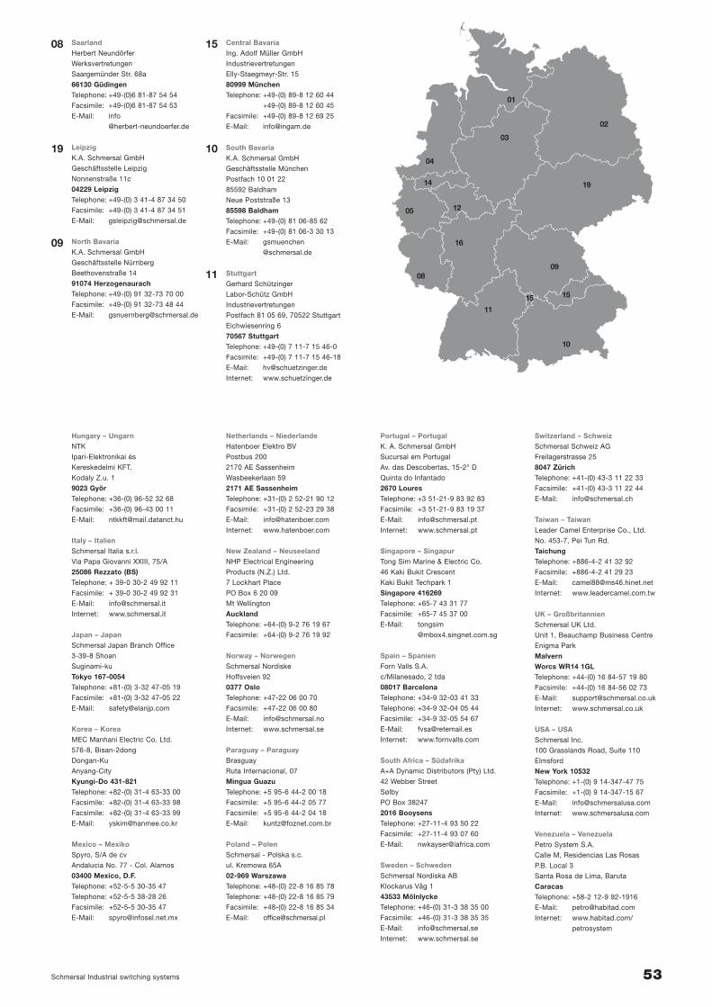
Hungary – UngarnNTK
Ipari-Elektronikai és
Kereskedelmi KFT.
Kodaly Z.u. 1
9023 GyörTelephone: +36-(0) 96-52 32 68
Facsimile: +36-(0) 96-43 00 11
E-Mail: [email protected]
Italy – ItalienSchmersal Italia s.r.l.
Via Papa Giovanni XXIII, 75/A
25086 Rezzato (BS)Telephone: + 39-0 30-2 49 92 11
Facsimile: + 39-0 30-2 49 92 31
E-Mail: [email protected]
Internet: www.schmersal.it
Japan – JapanSchmersal Japan Branch Office
3-39-8 Shoan
Suginami-ku
Tokyo 167-0054Telephone: +81-(0) 3-32 47-05 19
Facsimile: +81-(0) 3-32 47-05 22
E-Mail: [email protected]
Korea – KoreaMEC Manhani Electric Co. Ltd.
576-8, Bisan-2dong
Dongan-Ku
Anyang-City
Kyungi-Do 431-821Telephone: +82-(0) 31-4 63-33 00
Facsimile: +82-(0) 31-4 63-33 98
Facsimile: +82-(0) 31-4 63-33 99
E-Mail: [email protected]
Mexico – MexikoSpyro, S/A de cv
Andalucia No. 77 - Col. Alamos
03400 Mexico, D.F.Telephone: +52-5-5 30-35 47
Telephone: +52-5-5 38-28 26
Facsimile: +52-5-5 30-35 47
E-Mail: [email protected]
Netherlands – NiederlandeHatenboer Elektro BV
Postbus 200
2170 AE Sassenheim
Wasbeekerlaan 59
2171 AE SassenheimTelephone: +31-(0) 2 52-21 90 12
Facsimile: +31-(0) 2 52-23 29 38
E-Mail: [email protected]
Internet: www.hatenboer.com
New Zealand – NeuseelandNHP Electrical Engineering
Products (N.Z.) Ltd.
7 Lockhart Place
PO Box 6 20 09
Mt Wellington
AucklandTelephone: +64-(0) 9-2 76 19 67
Facsimile: +64-(0) 9-2 76 19 92
Norway – NorwegenSchmersal Nordiske
Hoffsveien 92
0377 OsloTelephone: +47-22 06 00 70
Facsimile: +47-22 06 00 80
E-Mail: [email protected]
Internet: www.schmersal.se
Paraguay – ParaguayBrasguay
Ruta Internacional, 07
Mingua GuazuTelephone: +5 95-6 44-2 00 18
Facsimile: +5 95-6 44-2 05 77
Facsimile: +5 95-6 44-2 04 18
E-Mail: [email protected]
Poland – PolenSchmersal - Polska s.c.
ul. Kremowa 65A
02-969 WarszawaTelephone: +48-(0) 22-8 16 85 78
Telephone: +48-(0) 22-8 16 85 79
Facsimile: +48-(0) 22-8 16 85 34
E-Mail: [email protected]
Portugal – PortugalK. A. Schmersal GmbH
Sucursal em Portugal
Av. das Descobertas, 15-2° D
Quinta do Infantado
2670 LouresTelephone: +3 51-21-9 83 92 83
Facsimile: +3 51-21-9 83 19 37
E-Mail: [email protected]
Internet: www.schmersal.pt
Singapore – SingapurTong Sim Marine & Electric Co.
46 Kaki Bukit Crescent
Kaki Bukit Techpark 1
Singapore 416269Telephone: +65-7 43 31 77
Facsimile: +65-7 45 37 00
E-Mail: tongsim
@mbox4.singnet.com.sg
Spain – SpanienForn Valls S.A.
c/Milanesado, 2 tda
08017 BarcelonaTelephone: +34-9 32-03 41 33
Telephone: +34-9 32-04 05 44
Facsimile: +34-9 32-05 54 67
E-Mail: [email protected]
Internet: www.fornvalls.com
South Africa – SüdafrikaA+A Dynamic Distributors (Pty) Ltd.
42 Webber Street
Sølby
PO Box 38247
2016 BooysensTelephone: +27-11-4 93 50 22
Facsimile: +27-11-4 93 07 60
E-Mail: [email protected]
Sweden – SchwedenSchmersal Nordiska AB
Klockarus Våg 1
43533 MölnlyckeTelephone: +46-(0) 31-3 38 35 00
Facsimile: +46-(0) 31-3 38 35 35
E-Mail: [email protected]
Internet: www.schmersal.se
Switzerland – SchweizSchmersal Schweiz AG
Freilagerstrasse 25
8047 ZürichTelephone: +41-(0) 43-3 11 22 33
Facsimile: +41-(0) 43-3 11 22 44
E-Mail: [email protected]
Taiwan – Taiwan Leader Camel Enterprise Co., Ltd.
No. 453-7, Pei Tun Rd.
TaichungTelephone: +886-4-2 41 32 92
Facsimile: +886-4-2 41 29 23
E-Mail: [email protected]
Internet: www.leadercamel.com.tw
UK – GroßbritannienSchmersal UK Ltd.
Unit 1, Beauchamp Business Centre
Enigma Park
MalvernWorcs WR14 1GLTelephone: +44-(0) 16 84-57 19 80
Facsimile: +44-(0) 16 84-56 02 73
E-Mail: [email protected]
Internet: www.schmersal.co.uk
USA – USASchmersal Inc.
100 Grasslands Road, Suite 110
Elmsford
New York 10532Telephone: +1-(0) 9 14-347-47 75
Facsimile: +1-(0) 9 14-347-15 67
E-Mail: [email protected]
Internet: www.schmersalusa.com
Venezuela – VenezuelaPetro System S.A.
Calle M, Residencias Las Rosas
P.B. Local 3
Santa Rosa de Lima, Baruta
CaracasTelephone: +58-2 12-9 92-1916
E-Mail: [email protected]
Internet: www.habitad.com/
petrosystem
SaarlandHerbert Neundörfer
Werksvertretungen
Saargemünder Str. 68a
66130 GüdingenTelephone: +49-(0)6 81-87 54 54
Facsimile: +49-(0)6 81-87 54 53
E-Mail: info
@herbert-neundoerfer.de
LeipzigK.A. Schmersal GmbH
Geschäftsstelle Leipzig
Nonnenstraße 11c
04229 LeipzigTelephone: +49-(0) 3 41-4 87 34 50
Facsimile: +49-(0) 3 41-4 87 34 51
E-Mail: [email protected]
North BavariaK.A. Schmersal GmbH
Geschäftsstelle Nürnberg
Beethovenstraße 14
91074 HerzogenaurachTelephone: +49-(0) 91 32-73 70 00
Facsimile: +49-(0) 91 32-73 48 44
E-Mail: [email protected]
Central BavariaIng. Adolf Müller GmbH
Industrievertretungen
Elly-Staegmeyr-Str. 15
80999 MünchenTelephone: +49-(0) 89-8 12 60 44
+49-(0) 89-8 12 60 45
Facsimile: +49-(0) 89-8 12 69 25
E-Mail: [email protected]
South BavariaK.A. Schmersal GmbH
Geschäftsstelle München
Postfach 10 01 22
85592 Baldham
Neue Poststraße 13
85598 BaldhamTelephone: +49-(0) 81 06-85 62
Facsimile: +49-(0) 81 06-3 30 13
E-Mail: gsmuenchen
@schmersal.de
StuttgartGerhard Schützinger
Labor-Schütz GmbH
Industrievertretungen
Postfach 81 05 69, 70522 Stuttgart
Eichwiesenring 6
70567 StuttgartTelephone: +49-(0) 7 11-7 15 46-0
Facsimile: +49-(0) 7 11-7 15 46-18
E-Mail: [email protected]
Internet: www.schuetzinger.de
08
19
09
15
10
11
01
03
04
14
02
05
08
16
19
09
11
15
10
12
15
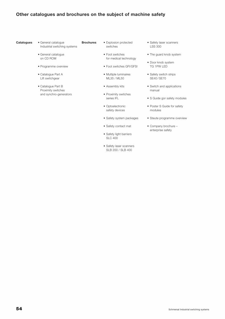
Other catalogues and brochures on the subject of machine safety
• General catalogueIndustrial switching systems
• General catalogueon CD ROM
• Programme overview
• Catalogue Part ALift switchgear
• Catalogue Part BProximity switchesand synchro-generators
• Explosion protected switches
• Foot switches for medical technology
• Foot switches GFI/GFSI
• Multiple luminaires ML35 / ML50
• Assembly kits
• Proximity switchesseries IFL
• Optoelectronic safety devices
• Safety system packages
• Safety contact mat
• Safety light barriers SLC 400
• Safety laser scanners SLB 200 / SLB 400
• Safety laser scannersLSS 300
• The guard knob system
• Door knob systemTG 1PW LED
• Safety switch stripsSE40 / SE70
• Switch and applicationsmanual
• S Guide gor safety modules
• Poster S Guide for safetymodules
• Steute programme overview
• Company brochure –enterprise safety
Catalogues Brochures
54 Schmersal Industrial switching systems
Safety Relay Modules
Protect SRB series
Version 2.0 – August 2002
Ho
us
ing
Dim
en
sio
ns
an
d W
irin
g D
iag
ram
s System requirements
• Minimum Pentium 90 PC with 16 MB RAM
• Windows® 95 or higher• Windows® NT V3.51 or higher
• Acrobat Reader 4.0To install Acrobat Reader execute the file ACRD4ENU in the directory \ACROREAD on the CD-ROM.

K. A. Schmersal GmbHIndustrielle SicherheitsschaltsystemeMöddinghofe 30D-42279 WuppertalTel.: +49-(0)2 02 / 64 74-0Fax: +49-(0)2 02 / 64 74-100Internet: http://www.schmersal.deE-Mail: [email protected]
08.02