sage 1x10 operation & maintenance manual
TRANSCRIPT

SAGE 1X10 Operation &
Maintenance Manual
S1X10-AAA-00001 V1.1

S1X10-AAA-00001 Baseline Document Version 1.1
Proprietary and Confidential to Schneider Electric
Schneider Electric North America Headquarters
800 Federal St
Andover, MA 01810
Phone: +1 (978) 794-0800
Schneider Electric USA, Inc
14400 Hollister St., Suite #400
Houston, TX 77066-5706
Phone: 1-713-920-6800
Fax: 1-713-920-6909
E-mail: [email protected]
SAGE 1X10 Operation & Maintenance Manual
For Reference Only
© Copyright 2018 by Schneider Electric
The information contained in this document is confidential and proprietary to Schneider Electric. It is not to be copied or disclosed for any
purpose except as specifically authorized in writing by Schneider Electric. Although the information contained herein was correct and verified at
the time of publication, it is subject to change without notice
Manual No. S1X10-AAA-00001
Document Approval
Rev Date Description ECO # Technical Review Admin. Approval
0.0 09-23-10 Initial Release N/A
1.0 12-04-14 Schneider Electric Template Chris Kerr
1.1 08-09-2018 Added Prop 65 Warning Chris Kerr
Chris Kerr,
Offer Manager, SAGE

SAGE RTU Product Line California Proposition 65
Version : 1.0
Date : 09-Aug-2018
Identification Product name: SAGE RTU Product Line
References involved: C3400 (SAGE 2400), C3800 (3030 M), C3700 (SAGE 1410), C3500 (SAGE 1430), C3600 (SAGE 1450), C3810 (LANDAC II), C3812 (SAGE 4400), C3414, C3132, C3133, C3140, C3230, C3231, C3232, C3233, C3235, C3241, C3243, C3244, C3247, C3248, C3263, C3320, C3321, C3322, C3330, C3360, C3429, C3430, C3432, C3437, C3438, C3476, C3831, C3835, C3861, C3439, C3442, C3443, C3444, C3445, C3446, C3447, C3448, C3449, C3450, C3451, C3452, C3453, C3454, C3455, C3456, C3457, C3459, C3460, C3462, C3464, C3465, C3466, C3467, C3468, C3469, C3470, C3471, C3472, C3473, C3474, C3475, C3477, C3478, C3479, C3480, C3481, C3482, C3484, C3485, C3486, C3487, C3488, C3489, C3490, C3491, C3492, C3493, C3494, C3495, C3530, C3532, C3534, C3550, C3551, C3552
Country - State USA - California
California Proposition 65 Warning Statement for California Residents
WARNING: This product can expose you to chemicals including Lead, which is known to the State of California to cause cancer and birth defects or other reproductive harm. For more information go to www.P65Warnings.ca.gov
Details of the supplier:
Supplier / Manufacturer : Schneider Electric USA, Inc.
Address : 14400 Hollister St. Suite 400 Houston, TX 77066
Phone : +1 (713) 920–6800 Web site : www.sage-rtu.com
www.schneider-electric.com
Page 1 / 1 California Proposition 65

Chapter 1 - Introduction SAGE 1X10 Operation & Maintenance Manual 5
S1X10-AAA-00001 Baseline Document Version 1.1
Proprietary and Confidential to Schneider Electric
1 Introduction Throughout this manual, the term SAGE 1X10 refers to the SAGE 1110, the SAGE 1210, the SAGE 1310
and the SAGE 1X10 collectively.
This user manual describes the operation and maintenance of the SAGE 1X10 Remote Terminal Unit
(RTU). It provides the detailed technical information necessary for installation, operation, setup, and
maintenance of the SAGE 1X10.
The Theory of Operation chapter should be used in conjunction with the Drawings appendix which
contains complete schematics and printed circuit assembly drawings. The drawings also include bills of
material for those users wishing to perform component level repair of failed assemblies.
The SAGE 1X10 Remote Terminal Unit is designed to operate in harsh environmental conditions. The
SAGE 1X10 is able to concentrate data gathered from a number of Intelligent Electronic Devices (IEDs)
and return that data to one or more SCADA master systems.
Features The SAGE 1X10 uses the latest electronic technology for reliability, speed and maintainability. It is
intended for use as a communications concentrator and is configured with two RS232 ports, one RS485
port, and one fiber optic port. The RTU can easily be expanded to include up to eight additional RS232
ports.
The SAGE 1X10 has the following new features:
• Easy-to-use Graphical User Interface (GUI) via Microsoft Internet Explorer or Chrome
• Embedded web server with HTTPS
• Built-in Ethernet with TCP/IP
• File Transfer Protocol (FTP) / Secure FTP
• May be configured either locally or remotely
• Point naming (no more counting point numbers to find your point of interest!)
• Point mapping with simple click and drop
• Data concentration – adds data from multiple IEDs to one database for fast polling
• Protocol conversion – convert multiple protocols to a standard protocol
• Built on a widely adopted Real-Time Operating system (RTOS)
• Employs standard PC/104 bus interface for CPU and Communication upgrades
• Relay Ladder Logic capability that supports all five IEC 61131-3 Languages
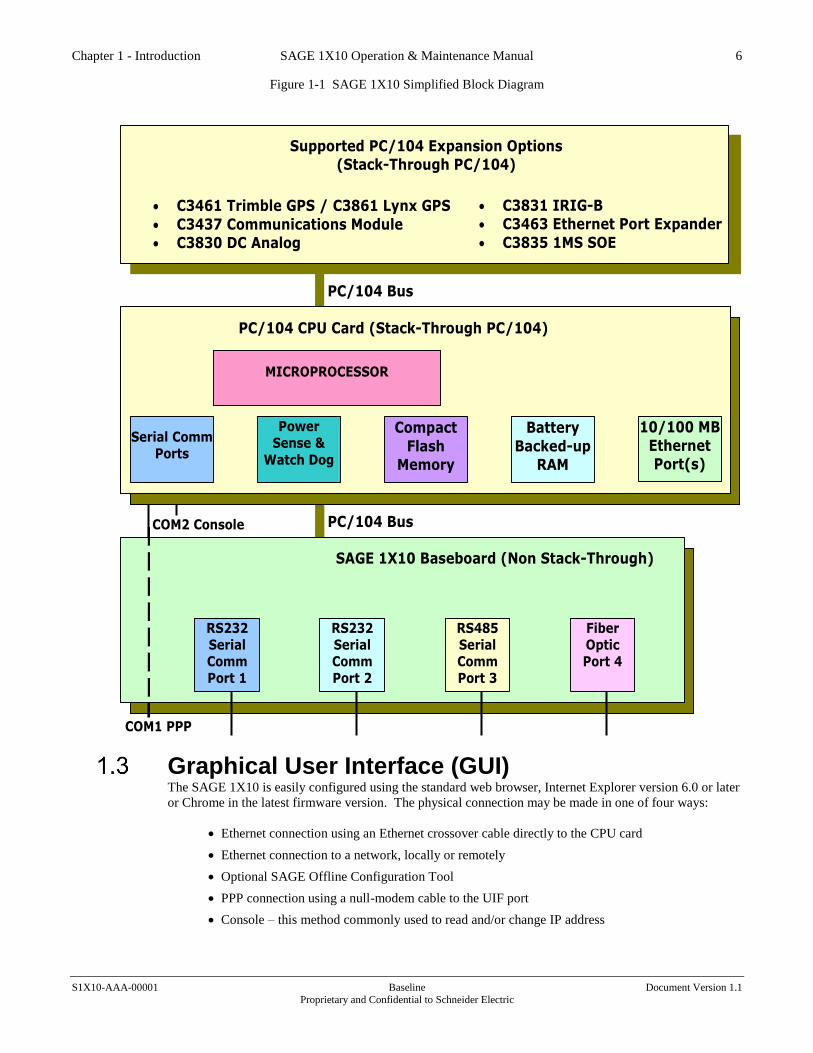
Architecture Figure 1-1 shows a simplified block diagram of the SAGE 1X10 that illustrates its general architecture and
major components. The SAGE 1X10 consists of a Baseboard and a microprocessor daughter board.
Additionally, the open architecture of the PC/104 interface provides for expanded functions. You may add
a PC/104 GPS receiver and/or C3437/C3438 Communication cards that allow up to eight additional RS232
Comm ports.
Chapter 1 - Introduction SAGE 1X10 Operation & Maintenance Manual 6
S1X10-AAA-00001 Baseline Document Version 1.1
Proprietary and Confidential to Schneider Electric
Figure 1-1 SAGE 1X10 Simplified Block Diagram
Serial Comm Ports
Power Sense &
Watch Dog
RAM
Memory
BIOS
Flash
Memory
STPC 486DX
Microprocessor
C3412 SBC1490 PC/104 CPU Card (Stack-Through PC/104)
PC/104 Bus
PC/104 Bus
• C3461 Trimble GPS / C3861 Lynx GPS
• C3437 Communications Module
• C3830 DC Analog
SAGE 1X10 Baseboard (Non Stack-Through)
RS232 Serial Comm Port 1
COM2 Console
COM1 PPP
Disk-On-
Chip Flash
Battery
Backed-up RAM
RS232 Serial Comm Port 2
RS485 Serial Comm Port 3
Fiber Optic Port 4
Serial Comm Ports
Power Sense &
Watch Dog
Compact
Flash
Memory
MICROPROCESSOR
PC/104 CPU Card (Stack-Through PC/104)
10/100 MB
Ethernet Port(s)
Battery
Backed-up
RAM
• C3831 IRIG-B
• C3463 Ethernet Port Expander
• C3835 1MS SOE
Supported PC/104 Expansion Options
(Stack-Through PC/104)
Graphical User Interface (GUI) The SAGE 1X10 is easily configured using the standard web browser, Internet Explorer version 6.0 or later
or Chrome in the latest firmware version. The physical connection may be made in one of four ways:
• Ethernet connection using an Ethernet crossover cable directly to the CPU card
• Ethernet connection to a network, locally or remotely
• Optional SAGE Offline Configuration Tool
• PPP connection using a null-modem cable to the UIF port
• Console – this method commonly used to read and/or change IP address

Chapter 1 - Introduction SAGE 1X10 Operation & Maintenance Manual 7
S1X10-AAA-00001 Baseline Document Version 1.1
Proprietary and Confidential to Schneider Electric
The GUI is designed around the classical client/server model. A web browser is all you need for your
client (PC) and you can browse any RTU product or any version of that product that supports our web
interface. All configuration data is stored on the RTU in the form of Extensible Markup Language (XML).
XML data is served up to the browser within HTML pages or transformed into HTML via Extensible
Stylesheet Language (XSL). In either case data is presented to the user in an intuitive format using
common design elements like forms, Radio Buttons, Spin Boxes, Alert Boxes, etc. for much of the data
entry.
The GUI supports File Transfer Protocol (FTP) or SFTP on the Secure Firmware to transfer files to/from
the RTU and the client. The file types include RTU applications, Web pages, Configuration files, and the
operating system. In short, every file within one RTU can be transferred to another RTU or parts of the
RTU file system can be upgraded as needed. This provides a powerful means of performing firmware
upgrades or configuration changes.
General Operational Considerations
Note: The initial setup is for a Username of “Admin” and a Password of “Telvent1!” (SAGE
1410 only). The Password for the other 1X10 RTUs is “Admin”.
Note: The initial TCP/IP address is 172.18.150.50 or 192.168.1.1 (depending on firmware)
Note: For the latest firmware, please see the appendix Accessing the Customer Website in the
config@WEB Software Users Guide
Point Mapping The RTUs of today must interface to a wide Varity of I/O and industry standard IEDs. This creates within
the RTU a large database of points that have been acquired by the RTU that must be transferred to one or
more master stations.
The SAGE 1X10 GUI supports an intuitive drag and drop point mapping scheme. Each point within the
RTU is named and scaled with user definable names and values. Scaling is used for local data display as
well as protocol count scaling for conversion of data from one protocol to another.
Communications Ports The SAGE 1X10 is polled by one or more Master Stations that are considered to be the Host. The basic
SAGE 1X10 has 4 serial communication ports (Port 1-4) and one additional User Interface (UIF) serial
communication port. Two host ports are fully RS232 compliant and can be operated in asynchronous or
synchronous modes. A third port supports RS485 communications and a fourth port supports fiber optic
serial communications.
The UIF is a dedicated RS-232 port that supports Point to Point Protocol (PPP). This port can be used for
initial setup, local maintenance and configuration updates. However, it is commonly used only to
configure the IP address of the Ethernet port. Once the Ethernet port is set up the UIF port will run
concurrently on the RS-232 port and the Ethernet port.
All SAGE RTU products support multiple RTU and IED protocols. This allows for data to be mapped
from IEDs to multiple masters via different RTU protocols. Example: If you were replacing your current
master station software that talks Series V protocol with a system that supports DNP your RTU could talk
to both the old master and the new master at the same time. This provides an excellent means of replacing
legacy RTU/MTU equipment without interruption to data acquisition.
An emerging need for RTU products is SCADA protocols to communicate over Ethernet all the way down
to the RTU. The SAGE 1X10 supports DNP over Ethernet.

Chapter 1 - Introduction SAGE 1X10 Operation & Maintenance Manual 8
S1X10-AAA-00001 Baseline Document Version 1.1
Proprietary and Confidential to Schneider Electric
1.5.1 PC/104 Communications Expansion The PC/104 C3437 module, along with the C3438 XT board, expands communication capabilities of the
SAGE 1X10 to as many as eight extra comm ports. All RS232 host ports are fully RS232 compliant and
can be operated in asynchronous or synchronous modes.
Relay Ladder Logic (RLL) The SAGE 1X10 supports a RLL Runtime Target that accepts applications that can be developed using any
one of the five IEC 61131-3 languages plus flow Charting. Programs are developed on an application
workbench that runs only on the client. Fully developed/debugged programs can be downloaded into the
SAGE 1X10 and activated for execution.
RLL applications have access to all the data within the RTU and make use of the powerful mapping
capabilities of the GUI. Output data from RLL applications can be viewed in real time data displays.
Packaging The SAGE 1X10 has a footprint of only 8"W x 5"L x 2"H and is designed to be retrofitted into a variety of
existing enclosures and apparatus. No special cooling or ventilation is required.

Chapter 2 - Specifications SAGE 1X10 Operation & Maintenance Manual 9
S1X10-AAA-00001 Baseline Document Version 1.1
Proprietary and Confidential to Schneider Electric
2 Specifications
User Computer Requirement OPERATING SYSTEM Windows XP and above with Internet Explorer Version 6
or above. Chrome can be used in later firmware versions.
If using XML to Excel macro, Microsoft Office 2003 or
above.
CPU/Memory NOTE: Please refer to CPU Manual for CPU specifications.
Communications Ports NUMBER OF PORTS 1 Console, 1 PPP User Interface, 4 Communications ports
on baseboard, up to 8 additional ports with optional
C3437 PC/104 cards and C3438 Comm Expansion card
FORMATS Baseboard: 2 ea. RS232C
1 ea. RS485
1 ea. Fiber optic
SPEEDS 300-9600 bps
PROTOCOLS Synchronous and asynchronous
ETHERNET One built-in 10/100BASE-T (RJ45) auto-negotiate (will
adjust to the speed and half/full duplex of the connecting
device)
C3463 PCA Ethernet 10/100 5-Port Switching Hub (Optional)
ETHERNET Five built-in 10/100BASE-T (RJ45) auto-negotiate (will
adjust to the speed and half/full duplex of the connecting
device)
Power Requirements INPUT VOLTAGE 9 to 33VDC required by the Baseboard
OPTIONAL POWER SOURCES 120/240VAC with added supply/battery charger;
12VDC, 48VDC, 129VDC with added DC/DC supply
INPUT POWER Approximately 6.25W max. for 10V to 33V
INPUT/OUTPUT ISOLATION 500 VDC
BATTERY CHARGER Optional external unit
Visual Indicators LEDs Input Power LED
5 LEDs per RS232 port (DCD, RX, RTS, TX, CTS)
2 LEDs per RS485 port (RX, TX)
2 LEDs per fiber optic port (RX, TX)
PC/104 CPU LEDs Please refer to CPU Manual

Chapter 2 - Specifications SAGE 1X10 Operation & Maintenance Manual 10
S1X10-AAA-00001 Baseline Document Version 1.1
Proprietary and Confidential to Schneider Electric
Environmental OPERATING TEMPERATURE –40° to +85° C
RELATIVE HUMIDITY 5% to 95%, non-condensing
TRANSIENT PROTECTION All user field connections designed to pass:
IEEE 472-1974,
ANSI C37.90-1979 (R1982)
ANSI C37.90.1-1989
Analog Inputs (Optional) Note: Optional analog inputs requires a C3830 PC/104 card and one or more XT AI card(s)
operating on a standard AI bus.
INPUT TYPE Differential
INPUT RANGES ±5VDC, 0-5VDC, 1-5VDC,
±1mA, 0-1mA, 4-20mA, 10-50mA
RESOLUTION 12 bits (11 bits plus sign)
COMPREHENSIVE ACCURACY ±0.25% FS between –40° and +85°C
REFERENCE VOLTAGES ±4.5V, +5V
CONVERSION RATE All analogs once per second
COMMON MODE RANGE ±10V
COMMON MODE REJECTION 80 dB @ 50/60Hz
NORMAL MODE REJECTION 60 dB @ 50/60Hz
INPUT RESISTANCE 10M ohm or greater
MAX INPUTS 256
XT CONFIGURATION 2 terminals per point (+ and -) with a shared shield
ground.

Chapter 3 - Installation SAGE 1X10 Operation & Maintenance Manual 11
S1X10-AAA-00001 Baseline Document Version 1.1
Proprietary and Confidential to Schneider Electric
3 Installation This chapter describes the normal installation and operation procedures for the SAGE 1X10 RTU. Prior to
moving the RTU assembly to the installation site, we recommend that you perform a preliminary functional
test to verify that the configuration is correct for the intended site and also to check for any undetected
shipping damage. Preliminary testing should be performed after the RTU has been setup using the
information in Chapter 2 of the config@WEB Software Users Guide.
General Installation Procedure The SAGE 1X10 is small enough (8"W x 5"L x 2"H) that it usually can be mounted in an existing cabinet.
All that is needed is four #8 screws and standoffs. Detailed mounting information may be found on
drawing C3700-600-00002 in the Drawings appendix of this manual. The entire board consumes less than
9 watts, so no special ventilation is needed.
The procedures for connecting field wiring to the RTU are provided in the following sections.
Figure 3-1 SAGE 1X10 Baseboard
S1310
TP6
+5V
DGND
TP1
TP5
+12VDB1 DB2
TP4
-12V
TP7
7.3728MHz
TP2
DGND
TP8
RTU-ADD#
TP3
DGND
DC
D
TX
CT
S
RX
RT
S
DC
D
TX
CT
S
RX
RT
S RX
TX
TX
RX
DC
D
INPUT POWER
RX
RT
S
CT
S
TX
Caution: The printed circuit assembly contains CMOS devices and is sensitive to static
discharge. Boards should be handled only at a grounded workstation. Avoid touching the
electronic components, jumpers, connectors, or the exposed etches on the boards when connecting
the field wiring.
Power Terminations Field input power will vary according to project requirements. The assembly includes circuit protection
devices for the field power. In a minimum configuration, however, field power is connected directly to the
Baseboard.

Chapter 3 - Installation SAGE 1X10 Operation & Maintenance Manual 12
S1X10-AAA-00001 Baseline Document Version 1.1
Proprietary and Confidential to Schneider Electric
The Baseboard (Figure 3-1) runs on +9 to +33VDC. If the field input power is the AC line or a DC source
other than +9 to +33VDC, the enclosure will include a power supply and separate terminations for field
power. In this case, the power supply will be pre-wired to the Baseboard. Refer to your RTU assembly
drawing for the input power terminal assignments. It will be clear from the drawing where to hook up the
hot and neutral or the field+ and field-, and chassis ground.
If the RTU is being directly powered from a +9 to +33VDC source with no switch or circuit protection
device between the source and Baseboard, the input power must be connected to terminal strip TB1 on the
Baseboard (see Figure 3-2). Make sure the input power is de-energized and then connect +9 to +33VDC to
terminal 1 and DC return to terminal 2.
Figure 3-2 Baseboard Power
Serial Comm Ports The SAGE 1X10 baseboard has 5 ports. One port is dedicated to the User Interface (UIF). The four other
ports (1 through 4) use a dual Serial Communications Controller and may be used for communications with
IEDs, MTUs, as a redundant channel to the primary master, or as a data concentrator for other RTUs. As
an option, you may also configure two C3437 PC/104 cards and a C3438 card for an additional eight
RS232 ports, as shown in Table 3-1.
3.3.1 RS232 Connections The pinout of the DB-9 RS232 connectors is summarized in Table 3-1. For the simplest connection, only
pins 2, 3, and 5 are actually required. The other pins are used for modem controls as well as synchronous
connections. The input pins receive signals from external sources while the output pins supply signals from
the RTU. Five signal lines for each RS232 channel are supplied with LEDs as indicated in the last column
of the table.
9-33VDCInput
Alternate EarthGround Connection
Switched DC Out (Input Supply). This can be
used to power comm equipment such as fiber
optic modem, radio, etc.
TB1
Chapter 3 - Installation SAGE 1X10 Operation & Maintenance Manual 13
S1X10-AAA-00001 Baseline Document Version 1.1
Proprietary and Confidential to Schneider Electric
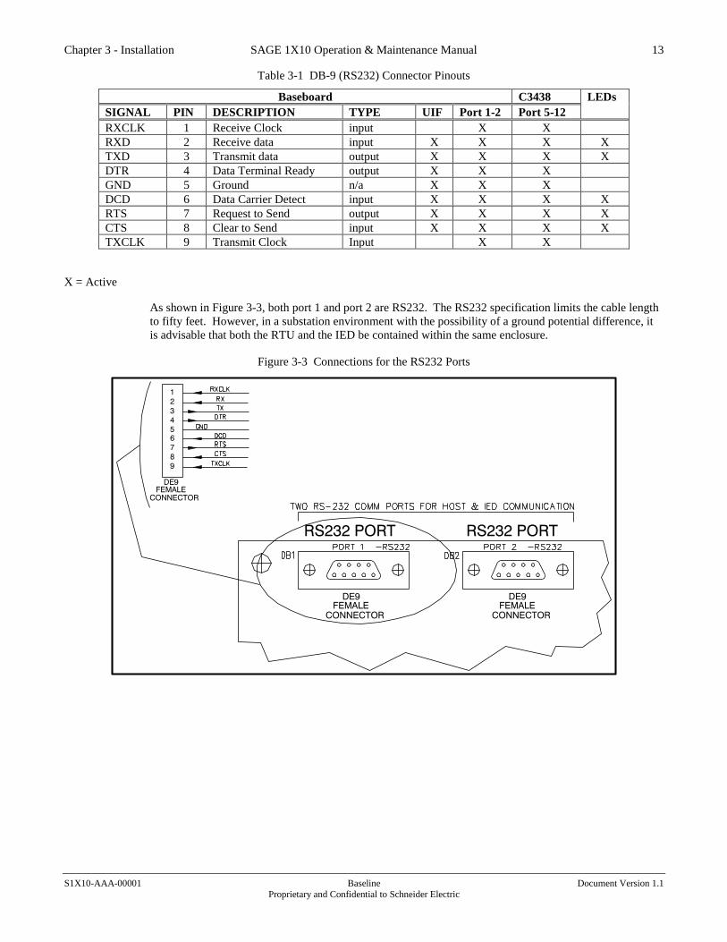
Table 3-1 DB-9 (RS232) Connector Pinouts
Baseboard C3438 LEDs
SIGNAL PIN DESCRIPTION TYPE UIF Port 1-2 Port 5-12
RXCLK 1 Receive Clock input X X
RXD 2 Receive data input X X X X
TXD 3 Transmit data output X X X X
DTR 4 Data Terminal Ready output X X X
GND 5 Ground n/a X X X
DCD 6 Data Carrier Detect input X X X X
RTS 7 Request to Send output X X X X
CTS 8 Clear to Send input X X X X
TXCLK 9 Transmit Clock Input X X
X = Active
As shown in Figure 3-3, both port 1 and port 2 are RS232. The RS232 specification limits the cable length
to fifty feet. However, in a substation environment with the possibility of a ground potential difference, it
is advisable that both the RTU and the IED be contained within the same enclosure.
Figure 3-3 Connections for the RS232 Ports
RS232 PORT
4
DE9
5
2
3
1
9
8
7
6
FEMALE
CONNECTOR
FEMALE
DE9
CONNECTOR
RS232 PORT
FEMALE
CONNECTOR
DE9
Chapter 3 - Installation SAGE 1X10 Operation & Maintenance Manual 14
S1X10-AAA-00001 Baseline Document Version 1.1
Proprietary and Confidential to Schneider Electric
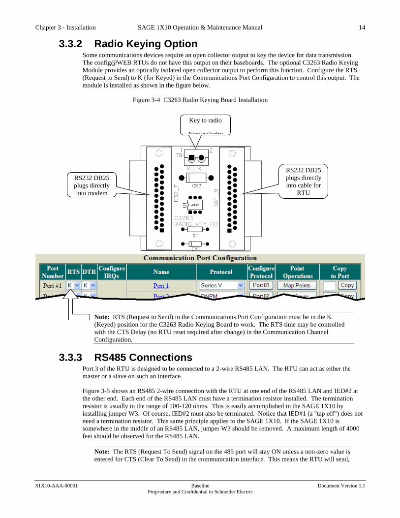
3.3.2 Radio Keying Option Some communications devices require an open collector output to key the device for data transmission.
The config@WEB RTUs do not have this output on their baseboards. The optional C3263 Radio Keying
Module provides an optically isolated open collector output to perform this function. Configure the RTS
(Request to Send) to K (for Keyed) in the Communications Port Configuration to control this output. The
module is installed as shown in the figure below.
Figure 3-4 C3263 Radio Keying Board Installation
Note: RTS (Request to Send) in the Communications Port Configuration must be in the K
(Keyed) position for the C3263 Radio Keying Board to work. The RTS time may be controlled
with the CTS Delay (no RTU reset required after change) in the Communication Channel
Configuration.
3.3.3 RS485 Connections Port 3 of the RTU is designed to be connected to a 2-wire RS485 LAN. The RTU can act as either the
master or a slave on such an interface.
Figure 3-5 shows an RS485 2-wire connection with the RTU at one end of the RS485 LAN and IED#2 at
the other end. Each end of the RS485 LAN must have a termination resistor installed. The termination
resistor is usually in the range of 100-120 ohms. This is easily accomplished in the SAGE 1X10 by
installing jumper W3. Of course, IED#2 must also be terminated. Notice that IED#1 (a "tap off") does not
need a termination resistor. This same principle applies to the SAGE 1X10. If the SAGE 1X10 is
somewhere in the middle of an RS485 LAN, jumper W3 should be removed. A maximum length of 4000
feet should be observed for the RS485 LAN.
Note: The RTS (Request To Send) signal on the 485 port will stay ON unless a non-zero value is
entered for CTS (Clear To Send) in the communication interface. This means the RTU will send,
RS232 DB25
plugs directly
into cable for
RTU
RS232 DB25
plugs directly
into modem
Key to radio
Note polarity

Chapter 3 - Installation SAGE 1X10 Operation & Maintenance Manual 15
S1X10-AAA-00001 Baseline Document Version 1.1
Proprietary and Confidential to Schneider Electric
but not receive. Always enter a non-zero value for CTS in the 485 port communications user
interface. See the appropriate protocol manual.
Figure 3-5 Connections for the RS485 Port
The RS485 port has an LED for TX and an LED for RX.
RS485 PORT FIBER OPTIC PORT
IED #2
IED #1

Chapter 3 - Installation SAGE 1X10 Operation & Maintenance Manual 16
S1X10-AAA-00001 Baseline Document Version 1.1
Proprietary and Confidential to Schneider Electric
3.3.4 Fiber Optic Connections Port 4 of the RTU is designed to be connected to a fiber optic point-to-point interface or a looped fiber
optic LAN. In both cases, the RTU can act as the master or a slave device. The fiber optic interface is
designed using LED transmitters and receivers with ST type connectors and needs nothing more than
simple multi-mode cable.
Figure 3-6 shows a point-to-point fiber optic connection. As shown, the maximum distance for a fiber
optic connection to an IED is 16000 feet (just over three miles). Please see Chapter 2 of the config@WEB
Software Users Guide to properly configure the fiber for ECHO and LONG cable. Figure 3-7 shows a
typical fiber loop for IEDs. Please note that the master device in such a loop would have its echo setting
set to OFF, but each of the slave devices (IEDs) would have their echo setting set to ON.
Figure 3-6 Fiber Optic Point-to-Point Connections
Figure 3-7 Typical Fiber Optic Loop for IEDs
FIBER OPTIC PORT
IED #1 (fiber modem – echo ON)
IED #5 (fiber modem – echo ON)
IED #4 (fiber modem – echo ON)
IED #3 (fiber modem – echo ON)
IED #2 (fiber modem – echo ON)
Master (fiber modem – echo OFF)
The fiber port has an LED for TX and an LED for RX.
FIBER OPTIC PORT
IED #3

Chapter 3 - Installation SAGE 1X10 Operation & Maintenance Manual 17
S1X10-AAA-00001 Baseline Document Version 1.1
Proprietary and Confidential to Schneider Electric
3.3.5 User Interface Connections There are four physical ways to connect to the SAGE 1X10:
• Ethernet connection to a network using a Straight-through cable to the CPU card
- Best way to gain remote access
• Ethernet connection locally using an Ethernet crossover cable to the CPU card
- Best way to gain local access
• PPP (Point-to-Point Protocol) connection using a null-modem cable to the UIF port
- Moderately slow; can still access RTU locally or even remotely with a dedicated comm.
Channel
• Console – this method commonly used to read and/or change IP address
Both the PPP and the Ethernet connections use the same GUI running on IE or Chrome. The difference is
that the PPP connection runs at 38,400 baud; the Ethernet connection runs at 10/100MB. When dealing
with a GUI, obviously the faster connection is much better. Therefore, the primary connection to the RTU
is Ethernet.
Please see the appendices in the config@WEB Software Users Guide for further connection information.
Jumpers All jumper designations and functions for the Baseboard and PC/104 Cards are found in Chapter 4
Maintenance of this document. It is important that the jumper configurations are properly set to prevent the
RTU from malfunctioning. Please check the jumper settings whenever an addition or change is made to the
RTU configuration.
PC/104 Expansion Installation The PC/104 interface provides for expanded functionality. PC/104 expansion cards are optional.
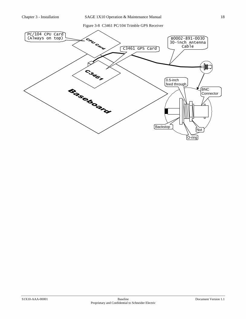
3.5.1 C3461 PC/104 Trimble GPS Receiver (Optional) The C3461 PC/104 Trimble GPS Receiver consists of the SATPAK Carrier Board and the Trimble GPS
Receiver Board riding piggy-back.
Caution: The SATPAK Carrier Board and the Trimble GPS Receiver Board are permanently
joined (See Figure 3-9). Do NOT attempt to separate the two. Also take care to avoid bending
any pins on the C3461 or the PC/104 assembly on which it is mounted.
1. As shown in Figure 3-8, the C3461 requires only a few steps for physical installation:
2. Unplug the CPU card.
3. Plug the C3461 into the baseboard.
4. Plug the CPU card into the top of the C3461. The CPU card must always be on top.
5. There is a 30-inch thin coax cable that attaches to the C3461 card. The BNC end may be mounted
through a 0.5-inch hole in the cabinet or other barrier. The assembly comes with a built-in O-ring
to afford some weather protection.
6. Mount the GPS antenna in an elevated, clear area outside the building.
7. Connect a suitable length of BNC cable* from the antenna to the cabinet-mounted BNC
connector.
Note: Schneider Electric supports a maximum length of 50 foot of RG-58 coaxial cable.
Chapter 3 - Installation SAGE 1X10 Operation & Maintenance Manual 18
S1X10-AAA-00001 Baseline Document Version 1.1
Proprietary and Confidential to Schneider Electric
Figure 3-8 C3461 PC/104 Trimble GPS Receiver
PC/104 CPU Card (Always on top) B0002-891-0030
30-inch Antenna Cable
C3461 GPS Card
Backstop
O-ring
Nut
BNC Connector
0.5-inch feed through

Chapter 3 - Installation SAGE 1X10 Operation & Maintenance Manual 19
S1X10-AAA-00001 Baseline Document Version 1.1
Proprietary and Confidential to Schneider Electric
3.5.2 C3461 GPS PC/104 Jumper Configuration for P1 & P2 P1 and P2 should have the jumpers and wire connection as shown below.
Figure 3-9 C3461 Board Layout
SATPAK-104 GPS Receiver Carrier Board
P1
U1
P2
Jumper Jumper
J1
J2
Trimble GPS Receiver

Chapter 3 - Installation SAGE 1X10 Operation & Maintenance Manual 20
S1X10-AAA-00001 Baseline Document Version 1.1
Proprietary and Confidential to Schneider Electric
3.5.3 C3437 PC/104 Comm Expansion & C3438 RS232 Port
Card (Optional) The C3437 is a PC/104 card which must be plugged into the top of any existing PC/104 cards. One C3437
will service four ports on a C3438 (see Figure 3-10). Another C3437 is required to service the remaining
four ports on the C3438.
Figure 3-10 Installing the C3437/C3438 Communications Expansion Cards
C3437 #1
C3437 #2
C3438
4 ports for
C3437 #2
Ribbon
Cables
C3438
4 ports for
C3437 #1
PC/104 CPU Card (Always on top)
3.5.3.1 C3437 IRQ (Interrupt) Selection The C3437 must be version B or above.
Board 1 Board 2
IRQ9 OUT OUT
IRQ3 OUT OUT
IRQ6 IN IN
IRQ7 OUT OUT
PD (Pull Down) OUT OUT
BOARD1 IN OUT

Chapter 3 - Installation SAGE 1X10 Operation & Maintenance Manual 21
S1X10-AAA-00001 Baseline Document Version 1.1
Proprietary and Confidential to Schneider Electric
3.5.3.2 C3438-002-REV-X, XT Board The XT board is used to provide 8 DB-9F terminations for two C3437 4 channel communications boards.
All signals in the DB-9F connector are RS232 levels and are configured as DTE (Data Terminal
Equipment).
Two ribbon cable connectors are provided to accept signals from the C3437 boards.
Connect the C3437 board(s) to the XT as follows:
C3438 Connector C3437
J1 Board 1
J2 Board 2
The DB-9F connectors are configured as follows:
C3437 C3437Channel C3438 Port RTU Channel
Board 1 1 1 5
Board 1 2 2 6
Board 1 3 3 7
Board 1 4 4 8
Board 2 1 5 9
Board 2 2 6 10
Board 2 3 7 11
Board 2 4 8 12
The pins in the DB-9F are used as follows:
Pin Signal Direction
1 RXCLK Input
2 RX# Input
3 TX# Output
4 DTR Output
5 DGND
6 DCD Input
7 RTS Output
8 CTS Input
9 TXCLK Input
Chapter 3 - Installation SAGE 1X10 Operation & Maintenance Manual 22
S1X10-AAA-00001 Baseline Document Version 1.1
Proprietary and Confidential to Schneider Electric
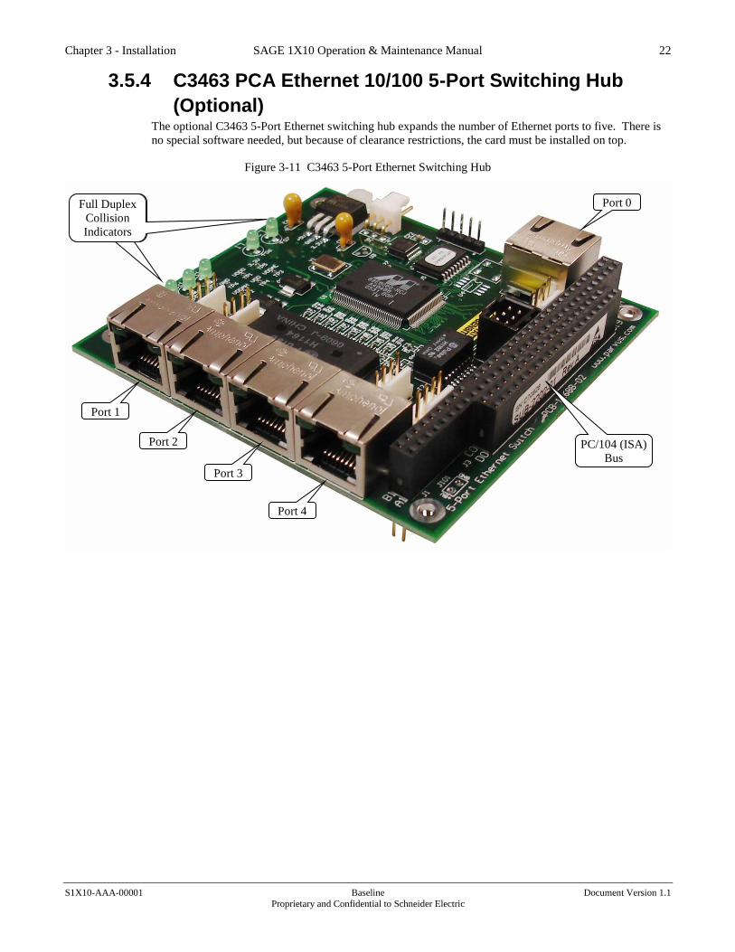
3.5.4 C3463 PCA Ethernet 10/100 5-Port Switching Hub
(Optional) The optional C3463 5-Port Ethernet switching hub expands the number of Ethernet ports to five. There is
no special software needed, but because of clearance restrictions, the card must be installed on top.
Figure 3-11 C3463 5-Port Ethernet Switching Hub
Port 1
Port 2
Port 3
Port 4
Port 0 Full Duplex
Collision
Indicators
Full Duplex
Collision
Indicators
PC/104 (ISA)
Bus

Chapter 3 - Installation SAGE 1X10 Operation & Maintenance Manual 23
S1X10-AAA-00001 Baseline Document Version 1.1
Proprietary and Confidential to Schneider Electric
3.5.5 C3831 PC/104 IRIG-B Card (Optional) The IRIG-B card pictured below is available for all SAGE RTUs except the S3030, which has built-in
IRIG-B.
Figure 3-12 C3831 PC/104 IRIG-B Card

Chapter 3 - Installation SAGE 1X10 Operation & Maintenance Manual 24
S1X10-AAA-00001 Baseline Document Version 1.1
Proprietary and Confidential to Schneider Electric
Figure 3-13 PC/104 Card Stacking
BASEBOARD
GPS
CPU
C3437 Comm Expansion Card #1
The order of these two boards is arbitrary C3437 Comm Expansion Card #2
The order of these two boards is arbitrary
C3463 Ethernet 5-Port Hub Must be on top
3.5.5.1 IRIG-B signal as a Input to the RTU If the RTU IRIG-B system is connected to an IRIG-B source, it must provide a B 0 2 X or B 1 2 X Time
Code Format signal to the RTU.
Modulation/Frequency (First Digit of IRIG-B Time Code Format) 0 - Pulse Width Code
1 - Sine Wave, Amplitude Modulated
Frequency/Resolution (Second Digit of IRIG-B Time Code Format) 2 - 1kHz/1ms
Coded Expressions (Third Digit of IRIG-B Time Code Format) 0 through 7 is acceptable. The RTU IRIG-B system uses only the BCDtoy (Binary-Coded-Decimal time-
of-year) Coded Expressions part of the IRIG-B data stream. The BCDtoy is included in Coded Expressions
0 to 7 of the IRIG-B data stream.
3.5.5.2 IRIG-B signal output from the RTU If the RTU IRIG-B system is driven by a time source in the RTU, the Time Code Format is B 0 2 2.
Modulation/Frequency (First Digit of IRIG-B Time Code Format) 0 - Pulse Width Code
Frequency/Resolution (Second Digit of IRIG-B Time Code Format) 2 - 1kHz/1ms.
Coded Expressions (Third Digit of IRIG-B Time Code Format) 2 - BCDtoy

Chapter 3 - Installation SAGE 1X10 Operation & Maintenance Manual 25
S1X10-AAA-00001 Baseline Document Version 1.1
Proprietary and Confidential to Schneider Electric
3.5.5.3 IRIG-B Reference The following is a link to the IRIG Standard 200-04 document for IRIG Serial Time Code Formats.
https://wsmrc2vger.wsmr.army.mil/rcc/manuals/200-04/TT-45.pdf
3.5.6 C3830 PC/104 AI Card The PC/104 Analog Input Module is an option that can be used with the SAGE 1X10, 1330, or 3030
models. It adds 256 traditional DC analog inputs to the I/O capabilities of the base unit. The PC/104
Analog Input module is easy to add by simply plugging it into the PC/104 bus. It is added in the same way
that a Serial Communication Expansion module or GPS Module is added to the PC/104 stack. Once the
card is added, a ribbon cable connects it to the first SAGE Analog Input XT card. Additional modules then
connect together in a daisy chain fashion.
• Add up to 256 analog input points
• All Standard input ranges supported
Figure 3-14 C3830 PC/104 AI Card
Chapter 3 - Installation SAGE 1X10 Operation & Maintenance Manual 26
S1X10-AAA-00001 Baseline Document Version 1.1
Proprietary and Confidential to Schneider Electric
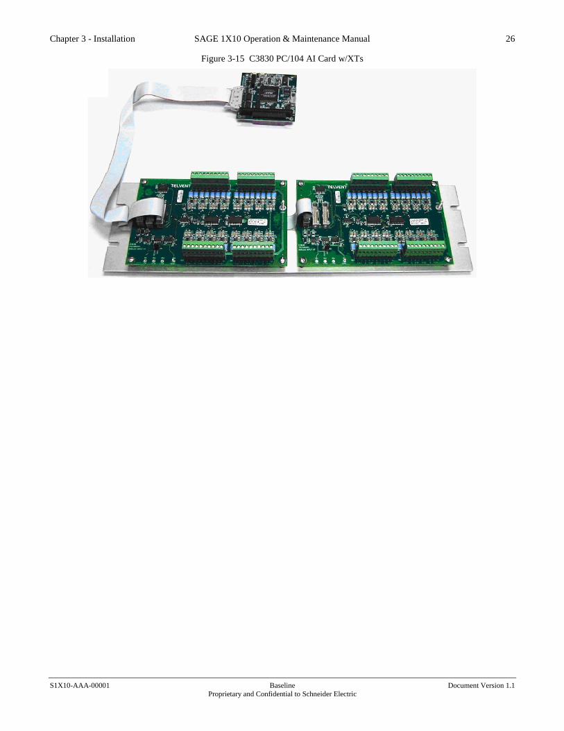
Figure 3-15 C3830 PC/104 AI Card w/XTs

Chapter 4 - Maintenance SAGE 1X10 Operation & Maintenance Manual 27
S1X10-AAA-00001 Baseline Document Version 1.1
Proprietary and Confidential to Schneider Electric
4 Maintenance This chapter describes the various calibration procedures for maintaining the SAGE 1X10. Those users
who desire a more thorough technical understanding of the SAGE 1X10 should refer to Chapter 5 Theory
of Operation which contains detailed descriptions of each module, and to the back of this manual, which
contains complete schematics, bills of materials, and printed circuit board assembly drawings.
The following equipment is recommended for performing routine maintenance and repair on SAGE 1X10
RTUs:
• General-purpose 3-1/2 digit DMM
The SAGE 1X10 requires no routine adjustments.
Comm Port Diagnostics The RTU includes a built-in test routine that allows limited testing of the communication ports. Click the
Command tab, then click Serial Comm. You will see a screen similar to Figure 4-1.
Figure 4-1 Command Communications Port Data
Under the Test Mode heading, select the type of test you wish from the pull-down menu for the port of
interest. The choices and the meaning of each type of test is listed below. See Figure 4-3 for the expected
results for each test.
Normal In the normal mode, the selected comm channel functions normally. Each channel will be in this mode
when the display is called up. Each channel is automatically restored to this mode when you exit from the
display or the RTU is reset.
Mark In the mark mode, the selected comm channel outputs a continuous stream of ones. Marks for the RS-232
channel are low (negative) voltage pulses, and low frequency (1,200Hz) for any attached 202 modem.
Space
Chapter 4 - Maintenance SAGE 1X10 Operation & Maintenance Manual 28
S1X10-AAA-00001 Baseline Document Version 1.1
Proprietary and Confidential to Schneider Electric
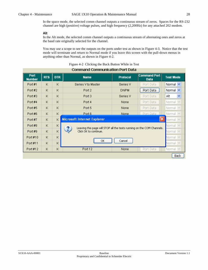
In the space mode, the selected comm channel outputs a continuous stream of zeros. Spaces for the RS-232
channel are high (positive) voltage pulses, and high frequency (2,200Hz) for any attached 202 modem.
Alt In the Alt mode, the selected comm channel outputs a continuous stream of alternating ones and zeros at
the baud rate originally selected for the channel.
You may use a scope to see the outputs on the ports under test as shown in Figure 4-3. Notice that the test
mode will terminate and return to Normal mode if you leave this screen with the pull-down menus in
anything other than Normal, as shown in Figure 4-2.
Figure 4-2 Clicking the Back Button While in Test

Chapter 4 - Maintenance SAGE 1X10 Operation & Maintenance Manual 29
S1X10-AAA-00001 Baseline Document Version 1.1
Proprietary and Confidential to Schneider Electric
Figure 4-3 Comm Port Test
+10V
-10V
0V
0 0 0
1 1 1
Scope connections:
RS232 Ports,
TX = pin 3
Return = Pin 5
2-channel Scope
connections:
RS485 Port,
Ch 1 to pin 1
Ch 2 to pin 2
Return = Pin 3
RS232 Space = 0 = +10V
Mark = 1 = -10V
Alt = 0/1 = +/-10V @ Baud rate
Port 4 (Fiber)
Functional test:
Look into TX BNC
connector:
Mark = Dark
Space = Light
Alt = Half Light
+4V
0V
0 0 0
1 1 1 RS485 Pin 1 Pin 2
+ –
Mark +4V +1V
Space +1V +4V
Alt alternates between +1V
and +4V @Baud rate
+1V
Note: A protocol must be assigned to the port undergoing Port Test
Note: Measure the RS485 pins with either two scope channels (pins 2 to 3) for a differential, or
one scope channel displaying pin 1 then pin 2 with pin 3 as the common.
Troubleshooting This section includes a brief guide to troubleshooting some of the more common problems that could occur
in the SAGE 1X10. If you are troubleshooting to the component level, the use of Chapter 5 Theory of
Operation and the drawings in the back of this manual will be helpful.
Caution: Do not insert or remove PC cards from the Baseboard unless the power supply has been
turned off.

Chapter 4 - Maintenance SAGE 1X10 Operation & Maintenance Manual 30
S1X10-AAA-00001 Baseline Document Version 1.1
Proprietary and Confidential to Schneider Electric
4.2.1 Removing PC/104 CPU Card or Compact Flash If you determine that the PC/104 CPU card or the Compact Flash must be removed or reinserted for any
reason, follow the directions below.
Note: Ensure power is OFF before disconnecting anything on the RTU.
Note: For those Compact Flashes that have a retaining clip, remove the clip carefully because if
the clip springs out of its holder, it can damage small parts on the CPU card.
Figure 4-4 PC/104 CPU Card with Ribbon Cable & Compact Flash
4.2.2 Visual Inspection A visual inspection of the equipment is often a good place to start the troubleshooting process. Look for
frayed or loose connections, blown fuses, and any indications of damage or excessive wear. Check that
switches and jumpers are in the right position and that input power is being supplied to the RTU. Verify
that the LEDs are providing expected indications compared to the present status conditions.
4.2.3 Data Display You can use the Data Display Menu to monitor the operation of input and output devices. The Data
Display can be compared to the LEDs as a means of status verification.
When removing CPU
card, leave large ribbon
cable connector attached
on this end; keep ribbon
cable with CPU card.
Slowly pull this connector from
socket straight up without
"rocking". Reinsert with steady
pressure.
Remove Compact Flash
slowly with a steady pull;
reinsert label up with
steady pressure.
Detach this end of ribbon
cable from baseboard.

Chapter 4 - Maintenance SAGE 1X10 Operation & Maintenance Manual 31
S1X10-AAA-00001 Baseline Document Version 1.1
Proprietary and Confidential to Schneider Electric
4.2.4 LED Indicators on Baseboard Refer to Figure 4-8 for the location of LEDs and Test Points on the Baseboard, and to Figure 4-5 for the
location of LEDs on the C3438 Communications Expansion Card. The SAGE 1X10 has been designed
with an ample number of LEDs to provide the operator an indication of the activities being performed by
the RTU.
Power The power LED (DS15) is illuminated and Baseboard power is provided when SW1 is on.
Communication All the communications ports (RS232, RS485, fiber optic), including the ports on the C3438, are
annunciated by LEDs as noted in Table 4-1, Figure 4-5, and Figure 4-8.
Table 4-1 Communication LEDs
Signal Baseboard C3438 Communications Expansion Card RS232 RS485 Fiber RS232
UIF CH-1 CH-2 CH-3 CH-4 CH-1 CH-2 CH-3 CH-4 CH-5 CH-6 CH-7 CH-8
Tx DS20 DS5 DS10 DS11 DS13 DS5 DS10 DS15 DS20 DS25 DS30 DS35 DS40
CTS DS19 DS4 DS9 DS4 DS9 DS14 DS19 DS24 DS29 DS34 DS39
RTS DS18 DS3 DS8 DS3 DS8 DS13 DS18 DS23 DS28 DS33 DS38
Rx DS17 DS2 DS7 DS12 DS14 DS2 DS7 DS12 DS17 DS22 DS27 DS32 DS37
DCD DS16 DS1 DS6 DS1 DS6 DS11 DS16 DS21 DS26 DS31 DS36
Figure 4-5 C3438 Board Layout
8 CHANNEL COMMUNICATION XT BOARD
BOARD 1 BOARD 2
PORT 1 PORT 2 PORT 3 PORT 4
PORT 5 PORT 6 PORT 7 PORT 8
.

Chapter 4 - Maintenance SAGE 1X10 Operation & Maintenance Manual 32
S1X10-AAA-00001 Baseline Document Version 1.1
Proprietary and Confidential to Schneider Electric
Analog Input Calibration (Optional C3830 Card) The analog input card has a simple calibration technique that is intended for use while the RTU is operating
on-site. The RTU has two dedicated internal references that provide 5V and 4.5V, which are used to
calibrate the A/D. Since the RTU is generating these references, only a precision voltmeter and a small
screwdriver are required to perform the calibration. See the figure below to locate adjustments and test
points.
1. Connect the voltmeter between TP3 (analog ground) and TP1 (5V reference)
2. Adjust potentiometer R4 until the meter indicates 5.000 Volts ±0.001V.
3. Connect the voltmeter between TP3 (analog ground) and TP2 (4.5V reference).
4. Adjust potentiometer R5 until the meter indicates 4.500 Volts ±0.001V.
This ensures the internal 100% and ±90% reference points are accurate.
Figure 4-6 C3830 PC/104 AI Card
+5V Test Point
& Adjustment +4.5V Test
Point &
Adjustment
Chapter 4 - Maintenance SAGE 1X10 Operation & Maintenance Manual 33
S1X10-AAA-00001 Baseline Document Version 1.1
Proprietary and Confidential to Schneider Electric
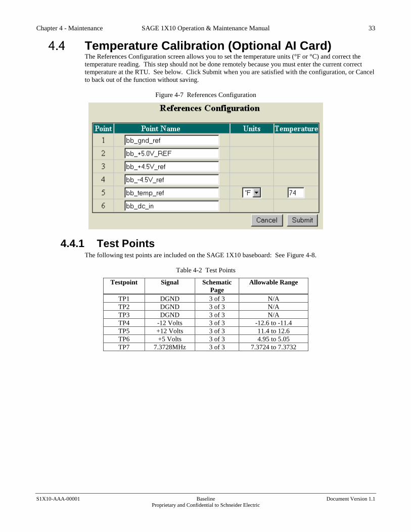
Temperature Calibration (Optional AI Card) The References Configuration screen allows you to set the temperature units (°F or °C) and correct the
temperature reading. This step should not be done remotely because you must enter the current correct
temperature at the RTU. See below. Click Submit when you are satisfied with the configuration, or Cancel
to back out of the function without saving.
Figure 4-7 References Configuration
4.4.1 Test Points The following test points are included on the SAGE 1X10 baseboard: See Figure 4-8.
Table 4-2 Test Points
Testpoint Signal Schematic
Page
Allowable Range
TP1 DGND 3 of 3 N/A
TP2 DGND 3 of 3 N/A
TP3 DGND 3 of 3 N/A
TP4 -12 Volts 3 of 3 -12.6 to -11.4
TP5 +12 Volts 3 of 3 11.4 to 12.6
TP6 +5 Volts 3 of 3 4.95 to 5.05
TP7 7.3728MHz 3 of 3 7.3724 to 7.3732

Chapter 4 - Maintenance SAGE 1X10 Operation & Maintenance Manual 34
S1X10-AAA-00001 Baseline Document Version 1.1
Proprietary and Confidential to Schneider Electric
Figure 4-8 Baseboard LED, Test Point, & Jumper Map
S1310
TP6
+5V
DGND
TP1
TP5
+12VDB1 DB2
TP4
-12V
TP7
7.3728MHz
TP2
DGND
TP8
RTU-ADD#
TP3
DGND
DC
D
TX
CT
S
RX
RT
S
DC
D
TX
CT
S
RX
RT
S RX
TX
TX
RX
DC
D
INPUT POWER
RX
RT
S
CT
S
TX
Jumper Positions, Baseboard The factory test Baseboard jumpers are positioned as noted in Table 4-3. This may not agree with the
configuration required for proper operation of your RTU. Determine the setup for your RTU by checking
the function column in the table. For a detailed view of the SAGE 1X10 baseboard, please see the
drawings at the back of this manual. See Figure 4-8 for location of jumpers. Please see the following
sections below for further jumper information.
Table 4-3 Jumper Positions, Baseboard
Jumper /
Position
Function Factory
Setting
Sheet
W1 / 1-2 Ties board’s DC ground to input – (TB1-2) IN 3 OF 3
W1 / 2-3 Isolates board’s DC ground from input
W2 / IN Asserts the non-maskable interrupt (used for
software debugging only)
1 OF 3
W2 / OUT OUT
W3 / IN Terminates RS485 line with 100 ohm resistor IN 2 OF 3
W3 / OUT Unterminates RS485 line

Chapter 4 - Maintenance SAGE 1X10 Operation & Maintenance Manual 35
S1X10-AAA-00001 Baseline Document Version 1.1
Proprietary and Confidential to Schneider Electric
Jumper Positions, C3461 PC/104 GPS Card Figure 4-9 Jumper Positions, C3461 PC/104 GPS Card
SATPAK-104 GPS Receiver Carrier Board
P1
U1
P2
Jumper Jumper
J1
J2
Trimble GPS Receiver

Chapter 4 - Maintenance SAGE 1X10 Operation & Maintenance Manual 36
S1X10-AAA-00001 Baseline Document Version 1.1
Proprietary and Confidential to Schneider Electric
Jumper Positions & Test Points, C3437 PC/104 Communications Card
.
Figure 4-10 Jumper Positions & Test Points, C3437 PC/104 Communications Card
IRQ9
IRQ3
IRQ6
IRQ7
PD
BOARD 1
TP1
CARD
ID#
TP4
+5V
TP2
CLK
TP3
DGND
4 PORT COMMUNICATION XT
Test Points
Jumpers (Default Position)
PC/104 Bus Connector
Ribbon Cable Connector for C3438 Cards
P1
P2

Chapter 4 - Maintenance SAGE 1X10 Operation & Maintenance Manual 37
S1X10-AAA-00001 Baseline Document Version 1.1
Proprietary and Confidential to Schneider Electric
I/O Locations & Functions Figure 4-11 I/O Locations & Functions
Power ON/OFF
CPU UIF – connects UIF port to PC/104 CPU
via ribbon cable
Comm ports 1 & 2 - RS232
Comm port 3 – RS485
Comm port 4 – fiber optic
Programming port for EPLD Dedicated
User Interface port (UIF)
9-33VDC input power & switched output power
S1410

Chapter 5 - Theory of Operation SAGE 1X10 Operation & Maintenance Manual 38
S1X10-AAA-00001 Baseline Document Version 1.1
Proprietary and Confidential to Schneider Electric
5 Theory of Operation This section provides detailed technical design information on the SAGE 1X10, including design of the
firmware and hardware. It is intended for use by those who wish to perform component-level
troubleshooting and repair on the modules. This section is based on the simplified block diagram shown in
Chapter 1. The schematic drawings and printed circuit assembly drawings contained in the back of this
manual can be used for a more detailed study.
Basic Architecture The SAGE 1X10 microprocessor controlled RTU is composed of a Baseboard and a Daughter board. Each
unit performs a specific part of the functions necessary for operation as an intelligent remote terminal unit
in a SCADA system. The Baseboard handles all communications with the Master Station(s). It maintains a
central database containing all of the input/output data, and issues various types of commands as they are
received from the Master Station(s).
5.1.1 PC/104 Architecture The open architecture of the PC/104 interface provides for expanded functions. You may add a PC/104
GPS receiver and/or C3437/C3438 Communication cards which allow up to eight additional Comm ports.
The PC/104 architecture is a compact version of the IEEE P996 (PC and PC/AT) bus, optimized for the
unique requirements of embedded systems applications. The PC/104 derives its name from the 104 signal
contacts on the two bus connectors (64 pins on P1, plus 40 pins on P2). The main differences from the
IEEE P996 are:
1. Reduced form-factor (3.550 x 3.775 inches)
2. Self-stacking, eliminating need for backplanes or card cages
3. Minimized component count and power consumption (typically 1-2 watts per module) and
reduced bus drive requirement (typically 4 mA)
SAGE 1X10 Microprocessor Overview Please refer to CPU manual for Processor Overview
Hardware Design
5.3.1 PC/104 Bus Interface/Connector The bus interface connector is compatible with the PC/104 Consortium specification.
Contact the Consortium at:
PC/104 Consortium
849 Independence Ave., Suite B
Mountain View, CA 94043
Phone: 650.903.8304
Fax: 650.967.0995
Email: [email protected]
The PC/104 standard is available on the web in downloadable PDF format at:
URL: http://www.pc104.org

Chapter 5 - Theory of Operation SAGE 1X10 Operation & Maintenance Manual 39
S1X10-AAA-00001 Baseline Document Version 1.1
Proprietary and Confidential to Schneider Electric
Figure 5-1 EPM-4 PC/104 CPU Card
PC/104 Connector
VersaLogic EPM-4
PC/104 CPU Compact
Flash
Ethernet
J4
J3
Console
Ribbon Cable
Red Stripe Ribbon Cable for PPP to J1
Power/Run LED
Compact Flash Access
LED
Speed
LED
Link/Activity
LED

Chapter 5 - Theory of Operation SAGE 1X10 Operation & Maintenance Manual 40
S1X10-AAA-00001 Baseline Document Version 1.1
Proprietary and Confidential to Schneider Electric
5.3.2 C3437 PC/104 4-Port Communication XT Each C3437 supports four external ports on a C3438 card. Up to eight ports are supported by using two
C3437 PC/104 cards and one C3438 Port XT. The C3437 is connected by ribbon cable to the C3438.
P1 acts as the PC/104 interface. The RTU acts as an 8bit slave ISA card and as such only decodes the first
nine addresses from the bus. Addresses SD15 - LA23 are in the connector but not brought out to the RTU.
The communication controller is a Zilog 85230. These devices have 4 byte TX FIFOs and 8 byte RX
FIFOs.
Figure 5-2 C3437 Board Layout
IRQ9
IRQ3
IRQ6
IRQ7
PD
BOARD 1
TP1
CARD
ID#
TP4
+5V
TP2
CLK
TP3
DGND
4 PORT COMMUNICATION XT
Test Points
Jumpers (Default Position)
PC/104 Bus Connector
Ribbon Cable Connector for C3438 Cards
P1
P2

Chapter 5 - Theory of Operation SAGE 1X10 Operation & Maintenance Manual 41
S1X10-AAA-00001 Baseline Document Version 1.1
Proprietary and Confidential to Schneider Electric
Table 5-1 I/O Port Addresses for the 4-Channel C3437 Communications Card
Port (hex) ACRONYM DEFINITON READ/WRITE
180-183 CS-COM1&2 85230 Ports READ & WRITE
184-187 CS-COM3&4 85230 Ports READ & WRITE
188-18B CS-COM5&6 85230 Ports READ & WRITE
18C-18F CS-COM7&8 85230 Ports READ & WRITE
5.3.3 C3438 8-Channel Communication XT Each port on the C3438 has its own RS232 driver. Each of the eight ports are identical and each can
receive both transmit and receive clocks.
Figure 5-3 C3438 Board Layout
8 CHANNEL COMMUNICATION XT BOARD
BOARD 1 BOARD 2
PORT 1 PORT 2 PORT 3 PORT 4
PORT 5 PORT 6 PORT 7 PORT 8

Chapter 5 - Theory of Operation SAGE 1X10 Operation & Maintenance Manual 42
S1X10-AAA-00001 Baseline Document Version 1.1
Proprietary and Confidential to Schneider Electric
5.3.4 C3461 PC/104 Trimble GPS Receiver The C3461 PC/104 Trimble GPS receiver consists of two boards; a PC/104 carrier card (SATPAK-104),
with a Trimble GPS receiver riding piggy-back. See Figure 5-4.
Figure 5-4 C3461 Board Layout
SATPAK-104 GPS Receiver Carrier Board
P1
U1
P2
Jumper Jumper
J1
J2
Trimble GPS Receiver
The SATPAK-104 communicates with the GPS receiver through a 16550 universal asynchronous
receiver/transmitter (UART). The UART converts the serial TTL data required by the GPS receiver to
parallel data required by the PC/l04 protocol. Simple push-on jumpers are used to configure the SATPAK-
104 for standard input/output base addresses (COM1, COM2, COM3, COM4) and any of the available bus
interrupt lines (IRQ3-IRQ7, IRQl0-1RQl2, IRQ14, or IRQ15). The J2 pass-through connector option must
be installed to access interrupt request signals IRQ10-IRQ12, IRQl4, and IRQl5. Custom programmable
logic is available if the user must decode base addresses other than those supported by the standard serial
communication addresses. The SATPAK-104 also provides signal level conditioning for RTCM-104 serial
differential correction signals (RS232 or RS422), and a large value l Farad capacitor to maintain the
almanac, ephemeris, and real-time clock of the GPS receiver after power is removed. The GPS receiver is
protected with a thermally resettable fuse in line with the +5V power to the GPS receiver. The IPPS signal
from the GPS receiver is available on connector P3 located on the SATPAK-104.

Chapter 5 - Theory of Operation SAGE 1X10 Operation & Maintenance Manual 43
S1X10-AAA-00001 Baseline Document Version 1.1
Proprietary and Confidential to Schneider Electric
The overall block diagram for the PC/104-Trimble receiver combination is shown in Figure 5-5.
Figure 5-5 GPS Receiver Block Diagram
Universal Asynchronous
RX/TX (UART)
Modular GPS
Receiver
+5V VBACKUP
1PPS
CHB TX
CHA TX
CHA/B TX SELECT PM
RS-422 RS-232
P3
Fuse Keep Alive
XCVR Logic Com Sel Int Sel
Addr Data Ctrl Int Req
+5V +5V
Antenna
5.3.5 Power Input The SAGE 1X10 Baseboard accepts +9 to +33VDC as a power input. Additional inputs of 48VDC and
129VDC may be used with a DC/DC converter. 120VAC or 240VAC may be used with the appropriate
supply/charger.
Terminal block input TB1-1 is used for the +9 to +33VDC input. The return is connected to TB1-2. The
input is surge protected by varistors RV2 and RV3 and reverse voltage protected by diode CR51 and fuse
F1. Over-voltage protection is provided by zener CR51. SW1 controls the power on-off while an LED
(DS15) indicates the presence of power to the Baseboard.
In minimum configurations, the entire RTU may be operated from this single power source. The logic
voltages needed for the operation of the rest of the system are derived from +9 to +33VDC by regulators
which generate the ±12 volts. Zener diodes (CR20, 21, 22) protect the output lines from over-voltage.
Communications Ports The SAGE 1X10 baseboard has 4 communications ports. The first two ports are general purpose RS232
ports and are accessed through a standard DB9 female connector. Each pin has electrical surge protection
and port status can be determined via hardware LED indication for TX, RX, RTS, CTS and DCD signals.
The third port is configured for RS485. It is has surge protection and supports hardware LED indication for
TX and RX data. This port is accessed through a 3 position terminal block that can accept up to 12 Gage
wire.
The fourth port is configured for fiber optic communications. Hardware LED indications for TX and RX
data are supported. This port is accessed through industry standard ST fiber connectors. The transmitter
and receiver are designed to operate with 850nm multi-mode fiber cable.

Chapter 6 - Drawings SAGE 1X10 Operation & Maintenance Manual 44
S1X10-AAA-00001 Baseline Document Version 1.1
Proprietary and Confidential to Schneider Electric
6 Drawings The following schematic and assembly drawings are included in this manual as a convenience to allow for
troubleshooting. See the 1X10 Drawings.pdf file for the full drawings.
C3700-A00-00000 Assembly Drawing, SAGE 1010 Baseboard Rev E 2 pages
C3700-200-00XXX Top Level Board Assembly, SAGE 1210 RTU Rev 0 1 page
C3700-300-00XXX Sage 1310 with 586 CPU Rev 0 1 page
C3700-301-XXXXX Sage 1310 with 586 CPU & 4 Port Ethernet SW Rev 0 1 page
C3700-400-00XXX Sage 1410 with LX-800 CPU Rev 0 1 page
C3700-401-XXXXX Sage 1410 with LX-800 CPU & 4 Port Ethernet SW Rev 0 1 page
C3700-002-REV-B Schematic, SAGE 1010 Baseboard Rev B 3 pages
C3700-002-PLDA1 PLD PGRM EP7032S Rev A 1 page
S1110-600-00001 Application Dwg. for S1110 Wiring Rev 0 1 page
S1410-600-00001 Application Dwg. for S1410 Wiring Rev 0 1 page
S1110-600-00002 Application Dwg. for S1X10 Outline & Mounting Rev 0 1 page
S1310-XXX-XXXXX S1310 RTU Assy with various Power Input Rev 0 6 pages