sailor 6120/30/40/50 system - the ast group 6130 mini-c lrit... · maintaining and repacking the...
TRANSCRIPT

INSTALLATION MANUAL
SAILOR 6120/30/40/50 System


SAILOR 6120/30/40/50 System
Installation manual
Document number: 98-131589-A
Release date: May 16, 2011

Disclaimer
Any responsibility or liability for loss or damage in connection with the use of this product and the accompanying documentation is disclaimed by Thrane & Thrane. The information in this manual is provided for information purposes only, is subject to change without notice and may contain errors or inaccuracies.
Manuals issued by Thrane & Thrane are periodically revised and updated. Anyone relying on this information should acquire the most current version e.g. from http://www.thrane.com or from the distributor.
Thrane & Thrane is not responsible for the content or accuracy of any translations or reproductions, in whole or in part, of this manual from any other source.
Copyright
© 2011 Thrane & Thrane A/S. All rights reserved.
Trademark Acknowledgements
• Thrane & Thrane is a registered trademark of Thrane & Thrane A/S in the European Union and the United States.
• Inmarsat is a registered trademark of the International Maritime Satellite Organisation (IMSO) and is licensed by IMSO to Inmarsat Limited and Inmarsat Ventures plc.
• SAILOR is a registered trademark of Thrane & Thrane A/S in the European Union, the United States and other countries.
• Other product and company names mentioned in this manual may be trademarks or trade names of their respective owners.

Safety summary 1
The following general safety precautions must be observed during all phases of operation, service and repair of this equipment. Failure to comply with these precautions or with specific warnings elsewhere in this manual violates safety standards of design, manufacture and intended use of the equipment. Thrane & Thrane assumes no liability for the customer's failure to comply with these requirements.
Observe marked areasUnder extreme heat conditions do not touch areas of units that are marked with this symbol, as it may result in injury.
Microwave radiation hazardsDuring transmission the antenna in this system radiates Microwave Power.This radiation may be hazardous to humans close to the antenna. When the system is powered, make sure that nobody gets closer than the recommended minimum safety distance of 0.3 m (1 ft.).
Keep away from live circuitsOperating personnel must not remove equipment covers. Only qualified maintenance personal must make component replacement and internal adjustment. Under certain conditions, dangerous voltages may exist even with the cable removed. To avoid injuries, always disconnect power and discharge circuits before touching them.
Compass safe distanceMinimum safety distance: 5 m from the Mini-C Terminal.
iii

About the manual 2
Naming conventions
This manual covers four different types of system. For information that applies to all four types, the following naming conventions are used:
Intended readers
This manual is an installation manual for the SAILOR 6120/30/40/50 Mini-C Systems. The manual is intended for installers of the system and service personnel. Personnel installing or servicing the system must be properly trained and authorized by Thrane & Thrane. It is important that you observe all safety requirements listed in the beginning of this manual, and install the system according to the guidelines in this manual.
Common name Used for
Mini-C System SAILOR 6120 SSA System
SAILOR 6130 LRIT System
SAILOR 6140 Maritime System
SAILOR 6150 Non-SOLAS System
Mini-C Terminal SAILOR 3027 SSA Terminal
SAILOR 3027 LRIT Terminal
SAILOR 3027 Maritime Terminal
SAILOR 3027 Non-SOLAS Terminal
iv

Manual overview
Note that this manual does not cover how to use the system. For information on usage refer to the user manual. Part numbers for related manuals are listed in the next section.
This manual has the following chapters:
• Introduction contains an overview of the system.
• Installing the system explains how to mount the units.
• Connecting the system explains how to connect the units in the system and shows wiring, pin-out and cable requirements.
• Configuration describes the tools available and explains the initial configuration of the system.
• Installation check and test contains a check list for verifying the physical installation and guidelines for testing the installation.
• Service and maintenance contains guidelines for handling, maintaining and repacking the SAILOR 6120/30/40/50 system.
Related documents
The below list shows the documents related to this manual and to the SAILOR 6120/30/40/50 Mini-C System.
Ref Title and descriptionDocument number
[1] SAILOR 6120/30/40/50 System, User manual
98-131590
[2] SAILOR 6006 and 6007 Message Terminal, Installation manual
98-130088
[3] THRANE 6194 Terminal Control Unit,Installation and user manual
98-131593
v

Typography
In this manual, typography is used as indicated below:
Bold is used for the following purposes:
• To emphasize words. Example: “Do not touch the antenna”.
• To indicate what the user should select in the user interface. Example: “Select SETTINGS > LAN”.
Italic is used to emphasize the paragraph title in cross-references.Example: “For further information, see Connecting Cables on page...”.
COURIER is used to indicate low level commands or text in the display. Example: “The display shows Distress”.
Online training for Thrane & Thrane partners
As a Thrane & Thrane Partner you have access to free of charge technical training in this SAILOR product covering installation, commissioning and repair.
For details on available training classes please consult the Thrane Academy at http://extranet.thrane.com/Training.aspx.
To learn more on CAN-bus as used with this product you may take the eLearning course “Introduction to CAN-bus” available at http://extranet.thrane.com/Training.aspx
[4] THRANE 6194 Software Interface Reference Manual
98-132853
[5] SAILOR 3027 Software Interface Reference Manual
98-132852
Ref Title and descriptionDocument number
vi

Table of contents
Chapter 1 Introduction
1.1 SAILOR 6120/30/40/50 system overview .....................2
1.2 Units in the system ....................................................6
Chapter 2 Installing the system
2.1 Unpacking ................................................................ 11
2.2 General installation requirements .............................13
2.3 Installing the SAILOR 3027 ........................................14
Chapter 3 Connecting the system
3.1 Connecting the units .................................................21
3.2 Grounding the units .................................................28
3.3 The CAN backbone ....................................................31
3.4 Connecting power .................................................... 32
3.5 Connectors and pin-out ...........................................38
Chapter 4 Configuration
4.1 Registering your SAILOR 3027 ..................................46
4.2 Configuration tools ..................................................48
4.3 Configuration using easyMail ..................................49
4.4 Configuration using commands ...............................54
Chapter 5 Installation check and test
5.1 Installation check list ...............................................58
5.2 Testing the SAILOR 6130 LRIT System .......................59
vii

Table of contents
5.3 Testing the system with easyMail ............................ 60
Chapter 6 Service and maintenance
6.1 Updating software ....................................................63
6.2 Maintenance guidelines ...........................................65
6.3 Service and repair ....................................................66
6.4 Available parts .........................................................67
App. A Technical specifications
A.1 SAILOR 6120/30/40/50 system specifications ........... 69
A.2 SAILOR 3027 specifications .......................................70
Glossary .........................................................................................73
Index .........................................................................................77
viii

Chapter 11111
Intro
duct
ion
Introduction 1
This chapter introduces the SAILOR 6120/30/40/50 systems and briefly describes the units. It has the following sections:
• SAILOR 6120/30/40/50 system overview
• Units in the system
1

Chapter 1: Introduction
1.1 SAILOR 6120/30/40/50 system overview
This manual describes four different systems:
• SAILOR 6120 SSA System
• SAILOR 6130 LRIT System
• SAILOR 6140 Maritime System
• SAILOR 6150 Non-SOLAS System
The following sections describe each of the systems and each of the units that are part of these systems.
1.1.1 SAILOR 6120 SSA System
The drawing below shows an example of a SAILOR 6120 SSA System.
The SSA (Ship Security Alert) System provides ships with alarm buttons, which can be activated in case of a piracy or terrorist attack. The alarm is a covert signal that has no sound and no flashing lights, so it is not seen nor heard by any intruders on board the ship.
SAILOR 3027
THRANE 6194
SSA buttons(not included)
SSA Terminal
2 SAILOR 6120/30/40/50 system overview
Chapter 1: Introduction1111
Intro
duct
ion
The SAILOR 6120 has three SSA buttons (two alarm buttons and one test button), which connect to the SAILOR 3027 SSA Terminal through the THRANE 6194 Terminal Control Unit. The CAN interface, which connects the SAILOR 3027 SSA Terminal to the THRANE 6194, also provides the power for the THRANE 6194.
1.1.2 SAILOR 6130 LRIT System
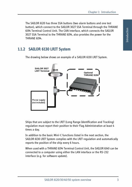
The drawing below shows an example of a SAILOR 6130 LRIT System.
Ships that are subject to the LRIT (Long Range Identification and Tracking) regulation must report their position to their Flag Administration at least 4 times a day.
In addition to the basic Mini-C functions listed in the next section, the SAILOR 6130 LRIT System complies with the LRIT regulation and automatically reports the position of the ship every 6 hours.
When used with a THRANE 6194 Terminal Control Unit, the SAILOR 6140 can be connected to a computer using either the LAN interface or the RS-232 interface (e.g. for software update).
SAILOR 3027LRIT Terminal
OptionalTHRANE 6194
SAILOR 6120/30/40/50 system overview 3
Chapter 1: Introduction
1.1.3 SAILOR 6140 Maritime System
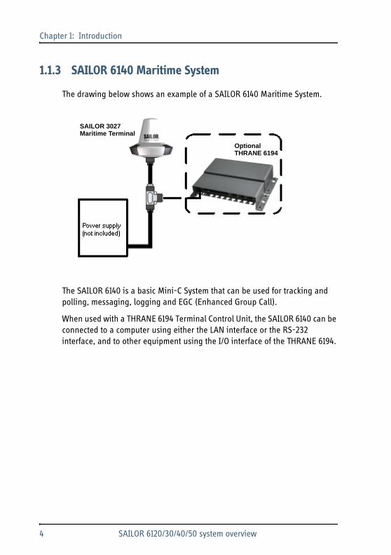
The drawing below shows an example of a SAILOR 6140 Maritime System.
The SAILOR 6140 is a basic Mini-C System that can be used for tracking and polling, messaging, logging and EGC (Enhanced Group Call).
When used with a THRANE 6194 Terminal Control Unit, the SAILOR 6140 can be connected to a computer using either the LAN interface or the RS-232 interface, and to other equipment using the I/O interface of the THRANE 6194.
SAILOR 3027Maritime Terminal
OptionalTHRANE 6194
4 SAILOR 6120/30/40/50 system overview

Chapter 1: Introduction1111
Intro
duct
ion
1.1.4 SAILOR 6150 Non-SOLAS System
The drawing below shows an example of a SAILOR 6150 Non-SOLAS System.
In addition to the basic Mini-C functions listed in the previous section, the SAILOR 6150 can be used in non-SOLAS Distress systems to send Distress alerts using the SAILOR 6108 Non-SOLAS Alarm Panel or SAILOR 3042E.
In non-SOLAS Distress systems a user interface is mandatory. You can use the easyMail application installed on a computer or on a SAILOR 6007 Message Terminal, or you can use a SAILOR 6006 Message Terminal, which has its own built-in user interface. See Configuration tools on page 48.
SAILOR 3027
SAILOR 6108
THRANE 6194
SAILOR 6007 Message Terminal orcomputer with easyMail(not included)
SAILOR 6120/30/40/50 system overview 5

Chapter 1: Introduction
1.2 Units in the system
1.2.1 SAILOR 3027 Mini-C Terminal
The SAILOR 3027 comes in different variants for different systems. The functions are different for each variant but the description below applies to all off these four variants:
• SAILOR 3027 SSA Terminal
• SAILOR 3027 LRIT Terminal
• SAILOR 3027 Maritime Terminal
• SAILOR 3027 Non-SOLAS Terminal
The SAILOR 3027 Mini-C Terminal is a mobile satellite terminal for the Inmarsat C system. It has a built-in LNA/HPA and an omni-directional antenna designed to operate on vessels. The housing is sealed and contains no user serviceable parts.
The SAILOR 3027 is very compact and is designed to operate in extreme weather conditions. It has a highly sensitive built-in GPS module with 50 channels. The antenna has an elevation angle of -15°, ensuring optimum communication even in rough weather.
6 Units in the system

Chapter 1: Introduction1111
Intro
duct
ion
The SAILOR 3027 connects to other equipment using a CAN bus interface, capable of carrying power as well as bi-directional communication.
For information on how to install the SAILOR 3027, see Installing the SAILOR 3027 on page 14.
1.2.2 THRANE 6194 Terminal Control Unit
The THRANE 6194 is used for the following purposes:
• For connecting
• covert alert buttons for use in Ship Security Alert (SSA) systems such as SAILOR 6120, or
• SAILOR 6108 Non-SOLAS Alarm Panels e.g. in Non SOLAS Distress systems (SAILOR 6150).
• For connecting other equipment that has Ethernet or RS-232 interface with the SAILOR 3027 terminal, which has a CAN interface.
The power for the THRANE 6194 is supplied through the CAN interface (extended input range 9-32 V DC).
Units in the system 7

Chapter 1: Introduction
1.2.3 SAILOR 6007 Message Terminal
On the SAILOR 6007 with the easyMail application installed you can read and write messages, monitor system status, change the configuration and test the system.
The SAILOR 6007 has a touch-screen interface and can be operated without a keyboard. You can also connect a keyboard if you prefer that.
An Ethernet interface connects to the SAILOR 3027 Mini-C Terminal through the THRANE 6194 Terminal Control Unit.
For information on how to install the SAILOR 6007, see SAILOR 6006 and 6007 Message Terminal, Installation manual [2].
For information on how to install and use the easyMail application, see Configuration using easyMail on page 49.
8 Units in the system

Chapter 1: Introduction1111
Intro
duct
ion
1.2.4 SAILOR 6006 Message Terminal (for SAILOR 6150 only)
With the SAILOR 6006 you can send distress alerts, read and write messages, monitor system status, change the configuration and test the system. The SAILOR 6006 has a Distress button for sending Distress alerts.
The SAILOR 6006 has a touch-screen interface and can be operated without a keyboard.
A CAN interface connects to the SAILOR 3027 Mini-C Terminal and an Ethernet interface connects to other equipment.
For information on how to install the SAILOR 6006, see SAILOR 6006 and 6007 Message Terminal, Installation manual [2].
Units in the system 9

Chapter 1: Introduction
10 Units in the system

Chapter 222
22
Inst
allin
g th
e sy
stem
Installing the system 2
This chapter describes the mechanical installation of the Mini-C Terminal. For information on cables and wiring of the system, see Connecting the system on page 21.
For information how to configure and use the system, see Initial configuration on page 52 and SAILOR 6120/30/40/50 System, User manual [1].
The following sections describe
• Unpacking
• General installation requirements
• Installing the SAILOR 3027
Mechanical installation of other units in the system, e.g. the THRANE 6194 Terminal Control Unit, is described in the individual installation manuals for the units. The names and numbers of the manuals are listed in Related documents on page v in the beginning of this manual.
2.1 Unpacking
2.1.1 Initial inspection
Inspect the shipping carton immediately upon receipt for evidence of damage during transport. If the shipping carton is severely damaged or water stained,
11

Chapter 2: Installing the system
request that the carrier's agent be present when opening the carton. Save the carton packing material for future use.
After unpacking the system, inspect it thoroughly for hidden damage and loose components or fittings. If the contents are incomplete, if there is mechanical damage or defect, or if the system does not work properly, notify your dealer.
2.1.2 What’s in the delivery
The following items are included in the delivery:
• SAILOR 3027 Mini-C Terminal, one of the following variants:
• SAILOR 3027 SSA Terminal
• SAILOR 3027 LRIT Terminal
• SAILOR 3027 Maritime Terminal
• SAILOR 3027 Non-SOLAS Terminal
• 1 Inch Pipe Adaptor and screw kit for Pipe Adaptor.
• Accessories kit including cables and connectors. For details, see Cables and connectors on page 27. Not included with SAILOR 6140.
• For SAILOR 6120 SSA System and SAILOR 6150 Non-SOLAS System only: THRANE 6194 Terminal Control Unit.
• For SAILOR 6150 Non-SOLAS System only: SAILOR 6108 Non-SOLAS Alarm Panel.
• Manuals:
• SAILOR 6120/30/40/50 Mini-C System, Installation manual (this manual) and
• SAILOR 6120/30/40/50 Mini-C System, User manual
Warning! To avoid electric shock, do not apply power to the system if there is any sign of shipping damage to any part of the front or rear panel or the outer cover. Read the safety summary at the front of this manual before installing or operating the system.
12 Unpacking

Chapter 2: Installing the system2
22
2
Inst
allin
g th
e sy
stem
2.2 General installation requirements
2.2.1 Power requirements
A SAILOR 6120/30/40/50 Mini-C System operates on 9-32 V DC. You may use any power supply or battery that meets the power requirements listed in this section and in Appendix A, Technical specifications.
Power consumption
The total power consumption varies primarily due to system activities. If you are using a battery, make sure it is capable of providing the required power. As a guideline, note the power consumption of the following equipment:
Important Only the SAILOR 3027 Mini-C Terminal must be placed outdoors. Place all other units in the system indoors! For information on environmental requirements to the units, refer to Technical specifications on page 69 or the individual installation manuals for the units.
Important If any additional NMEA2000 equipment is connected to the CAN bus, the power supply must be 15 V DC (nominal). To convert your power supply to 15 V DC you may use a SAILOR 6090 Power Converter or a SAILOR 6081 PSU and Charger from Thrane & Thrane.
Unit Idle power Max. power
SAILOR 3027 Mini-C Terminal 1.85 W 30 W
THRANE 6194 Terminal Control Unit 1 W 7 W
SAILOR 6006 Message Terminal(12 V DC - 24 V DC)
12 W 20 W
General installation requirements 13

Chapter 2: Installing the system
2.3 Installing the SAILOR 3027
2.3.1 Placing the SAILOR 3027 Mini-C Terminal
Place the terminal outdoors on the ship. Before mounting the terminal, consider the following:
• Safety distance: 1 ft. (0.3 m).Place the terminal so that no person can accidently get closer to the terminal than the safety distance 1 ft. (0.3 m).
• Distance to exhaust fumes.Do not place the terminal close to the funnel directly exposed to exhaust fumes.
• Distance to heat.Do not place the terminal close to any heat source.
• Distance to other equipment.Keep the following distances between the terminal and other equipment:
• Compass safe distance: > 5 m (distance to magnetic compass)
• HF antennas: > 5 m
• VHF antennas: > 4 m
• Other Inmarsat C terminals: > 0.5 m
14 Installing the SAILOR 3027
Chapter 2: Installing the system2
22
2
Inst
allin
g th
e sy
stem
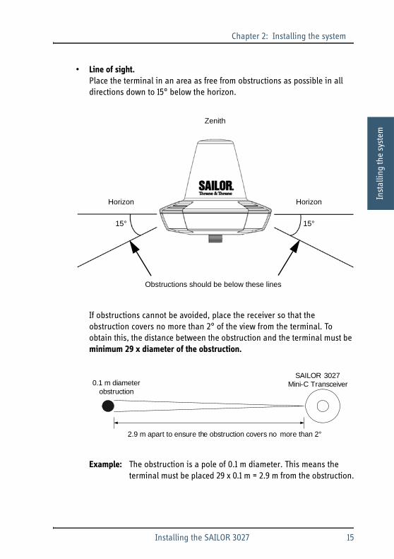
• Line of sight.Place the terminal in an area as free from obstructions as possible in all directions down to 15° below the horizon.
If obstructions cannot be avoided, place the receiver so that the obstruction covers no more than 2° of the view from the terminal. To obtain this, the distance between the obstruction and the terminal must be minimum 29 x diameter of the obstruction.
Example: The obstruction is a pole of 0.1 m diameter. This means the terminal must be placed 29 x 0.1 m = 2.9 m from the obstruction.
Zenith
Horizon
15°
Horizon
15°
Obstructions should be below these lines
2.9 m apart to ensure the obstruction covers no more than 2°
SAILOR 3027 Mini-C Transceiver0.1 m diameter
obstruction
Installing the SAILOR 3027 15

Chapter 2: Installing the system
• Power source available.The power source must be placed as close as possible to the terminal.
• Grounding available.Make sure that the shield of the CAN cable is connected to a proper ground, i.e. the ship’s structure/hull. This is very important in order to protect persons and equipment from lightning and safely bypass interference from Radar, VHF/MF/HF radio equipment and other environmental sources of interference.
Important Do not make the ground connection at the SAILOR 3027 end of the CAN cable. Instead, connect the shield of the CAN cable to ship ground at the power supply.
16 Installing the SAILOR 3027
Chapter 2: Installing the system2
22
2
Inst
allin
g th
e sy
stem
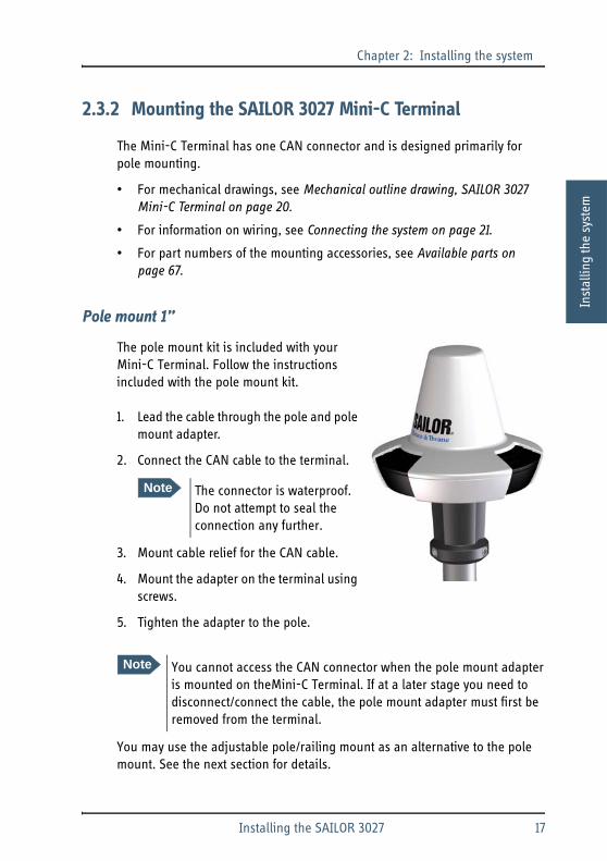
2.3.2 Mounting the SAILOR 3027 Mini-C Terminal
The Mini-C Terminal has one CAN connector and is designed primarily for pole mounting.
• For mechanical drawings, see Mechanical outline drawing, SAILOR 3027 Mini-C Terminal on page 20.
• For information on wiring, see Connecting the system on page 21.
• For part numbers of the mounting accessories, see Available parts on page 67.
Pole mount 1”
The pole mount kit is included with your Mini-C Terminal. Follow the instructions included with the pole mount kit.
1. Lead the cable through the pole and pole mount adapter.
2. Connect the CAN cable to the terminal.
3. Mount cable relief for the CAN cable.
4. Mount the adapter on the terminal using screws.
5. Tighten the adapter to the pole.
You may use the adjustable pole/railing mount as an alternative to the pole mount. See the next section for details.
Note The connector is waterproof. Do not attempt to seal the connection any further.
Note You cannot access the CAN connector when the pole mount adapter is mounted on theMini-C Terminal. If at a later stage you need to disconnect/connect the cable, the pole mount adapter must first be removed from the terminal.
Installing the SAILOR 3027 17

Chapter 2: Installing the system
Adjustable pole/railing mount 1” and 1½” (optional)
The adjustable pole/railing mount kit is available from Thrane & Thrane (see Available parts on page 67). When mounting the adjustable pole/railing mount follow the instructions included with the kit. The adjustable pole/railing mount fits 1” and 1½” poles and can be mounted on a vertical or horizontal pole.
Do as follows:
1. Attach the pole/railing mount to the pole using the included nuts and spacers. The drawing below and on the next page show the vertical and the horizontal assembly.
2. Tighten the nuts.
3. Place the large spacer between the SAILOR 3027 Mini-C Terminal and the pole/railing mount.
4. Fasten the Mini-C Terminalto the pole/railing mount using the 3 screws and spacers.
5. Tighten the screws.
6. Connect the CAN cable to the connector in the bottom of the Mini-C Terminal.
7. Mount cable relief for the CAN cable.
Vertical pole:
18 Installing the SAILOR 3027

Chapter 2: Installing the system2
22
2
Inst
allin
g th
e sy
stem
Horizontal pole:
Installing the SAILOR 3027 19

Chapter 2: Installing the system
Mechanical outline drawing, SAILOR 3027 Mini-C Terminal
ø170.5
ø16
4.6
M4 x 3Length of thread: 6 mm
120°
15
7 145
Connector housingcustom made
ø64
20 Installing the SAILOR 3027

Chapter 333
33
Conn
ectin
g th
e sy
stem
Connecting the system 3
This chapter explains how to connect the units in the SAILOR 6120/30/40/50 system and describes connectors, pin-out and cable requirements. It has the following sections:
• Connecting the units
• Grounding the units
• The CAN backbone
• Connecting power
• Connectors and pin-out
3.1 Connecting the units
Before connecting the units, read all sections in this chapter.
Connect the units according to the Wiring overview on the next pages and the requirements in this chapter.
Important Do not connect and switch on the power supply until all other units are connected!
21

Chapter 3: Connecting the system
3.1.1 Wiring overview
The cables and connectors marked with W and C in the drawings are listed in the table in Cables and connectors on page 27.
SAILOR 6120 SSA System
The drawing below shows the wiring of a basic SAILOR 6120 SSA System.
If you have more than two alert buttons, you can connect an alert button to each of the terminal blocks X7 to X12, using the same pins as in X8 and X10 shown above.
Note In all the Mini-C Systems you can also connect a computer. For details, see SAILOR 6120/30/40/50 with a computer on page 26.
THRANE 6194Terminal Control Unit
SAILOR 3027SSA Terminal
CA
N
CAN bus
CAN X2
Ship ground (hull)
Power supply
+
-DC output
ShieldW1
W3
C1
(Chassis)
SSAtest
button
SSAalert
button
SSAalert
button
1 2 3 1 2 3X8 X10
3
X14
1 2 4
W2
Bro
wn
Bro
wn
Gre
en
Gre
en
Yel
low
Yel
low
Bro
wn
Yel
low
Gre
en
Wh
ite
(Chassis)
22 Connecting the units

Chapter 3: Connecting the system 33
33
Conn
ectin
g th
e sy
stem
SAILOR 6130 LRIT System and SAILOR 6140 Maritime system
The drawing below shows the wiring of a basic SAILOR 6130 LRIT System or SAILOR 6140 Maritime System.
SAILOR 3027LRIT Terminal
CA
N
CAN bus
Ship ground (hull)
Power supply
+
-DC output
ShieldW1
W3
C1
(Chassis)
Connecting the units 23
Chapter 3: Connecting the system
SAILOR 6150 Non-SOLAS System
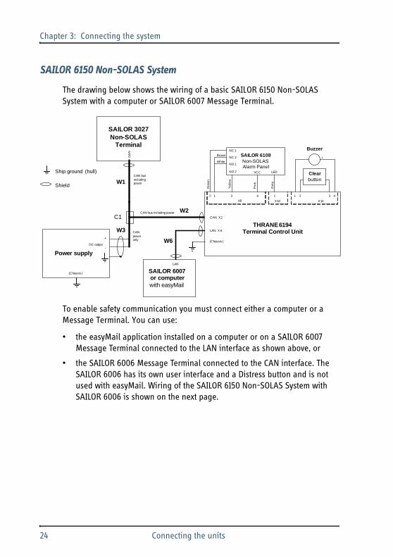
The drawing below shows the wiring of a basic SAILOR 6150 Non-SOLAS System with a computer or SAILOR 6007 Message Terminal.
To enable safety communication you must connect either a computer or a Message Terminal. You can use:
• the easyMail application installed on a computer or on a SAILOR 6007 Message Terminal connected to the LAN interface as shown above, or
• the SAILOR 6006 Message Terminal connected to the CAN interface. The SAILOR 6006 has its own user interface and a Distress button and is not used with easyMail. Wiring of the SAILOR 6150 Non-SOLAS System with SAILOR 6006 is shown on the next page.
THRANE 6194Terminal Control Unit
SAILOR 3027Non-SOLAS
Terminal
CA
N
CAN bus including power
CAN X2
Ship ground (hull)
Power supply
+
-DC output
ShieldW1
W3
C1
(Chassis )
Clearbutton
SAILOR 6108Non-SOLASAlarm Panel
NC 1
LED
31 4 1
X8 X10
3
X14
1 2 4
NC 2
NO 1
NO 2
Buzzer
2
VCC
W2
+
SAILOR 6007or computerwith easyMail
LAN
CAN bus including power
LAN X 6
Gre
y
Pin
k
Ye
llow
Brown
White
Gre
en
(Chassis )
W6
CAN power only
24 Connecting the units

Chapter 3: Connecting the system 33
33
Conn
ectin
g th
e sy
stem
The drawing below shows the wiring of a basic SAILOR 6150 Non-SOLAS System using the SAILOR 6006 Message Terminal.
You can connect two SAILOR 6108 Non-SOLAS Alarm Panels to the system. The second SAILOR 6108 must be connected to X12 with the same pins as in X8, and share pin 1 in X10 with the first SAILOR 6108.
For further information on the THRANE 6194 see THRANE 6194 Terminal Control Unit, Installation and user manual [3].
THRANE 6194Terminal Control Unit
SAILOR 3027Non-SOLAS
Terminal
CA
N
CAN bus including power
CAN X2
Ship ground (hull)
Power supply
+
-DC output
ShieldW1
W3
C1
(Chassis)
Clearbutton
SAILOR 6108Non-SOLASAlarm Panel
NC 1
LED
31 4 1
X8 X10
3
X14
1 2 4
NC 2
NO 1
NO 2
Buzzer
2
VCC
W2
+
SAILOR 6006
C2 CAN bus including power
CAN bus without power
W4
Gre
y
Pin
k
Ye
llow
Brown
White
Gre
en
(Chassis )
CAN X5
+
-DC output
X4, DC input
W7
Connecting the units 25

Chapter 3: Connecting the system
SAILOR 6120/30/40/50 with a computer
If you need to connect a computer to your Mini-C System, you must use a THRANE 6194 Terminal Control Unit, which connects to your system through the CAN interface. If the system is a SAILOIR 6120 SSA System or a SAILOR 6150 Non-SOLAS System, the THRANE 6194 is delivered with your system.
The below drawing shows the wiring. You may connect a SAILOR 6007 Message Terminal to the LAN interface instead of a computer.
THRANE 6194Terminal Control Unit
SAILOR 3027Terminal
CA
N
CAN bus
CAN X2
LA
N
RS
-232
Ship ground (hull)
Power supply
+
-DC output
Shield
PC or SAILOR 6007
LA
N
W1
W3
W6
C1
(Chassis)
COM port
RS-232 or LAN
W2
W5(Chassis )
26 Connecting the units

Chapter 3: Connecting the system 33
33
Conn
ectin
g th
e sy
stem
3.1.2 Cables and connectors
To see where the cables (W) and connectors (C) are located, refer to the drawings on the previous pages. The below table lists the cables and connectors from the drawings.
Cable Type Included/not included
W1 NMEA 2000 Mini Device Cable Included (30 m) with SAILOR 6120 and SAILOR 6130
W2 NMEA 2000 Micro Device Cable Included (6 m) with THRANE 6194
W3 NMEA 2000 Mini Device Cable Included (6 m) with all systems, except SAILOR 6140
W4 NMEA 2000 Micro Device Cable Included (6 m) with SAILOR 6150 only
W5 Straight through RS-232 serial cable with 9-pin D-sub connector (max. 15 m)
Not included, must be purchased separately
W6 Cat. 5E LAN cables, shielded (max. 100 m)
Not included, must be purchased separately
W7 Power cable to Message Terminal Included with the message Terminal
C1 Mini/Micro NMEA 2000 T-connector
Included (1 pcs.) with all systems, except SAILOR 6140
C2 Micro NMEA 2000 T-connector Included (1 pcs.) with SAILOR 6150 only
Connecting the units 27

Chapter 3: Connecting the system
As an alternative to the NMEA connectors you may use a CAN connection box, (part number 406208A).
For a list of additional cables and connectors available from Thrane & Thrane, see Available parts on page 67.
If you are using a THRANE 6194 Terminal Control Unit, refer also to the manual THRANE 6194 Terminal Control Unit, Installation and user manual [3].
3.2 Grounding the units
Make sure you have a suitable grounding location for grounding the units, preferably close to the power supply. See page 16 in the section Placing the SAILOR 3027 Mini-C Terminal.
3.2.1 SAILOR 3027 Mini-C Terminal
You may use a special CAN cable, containing only the power wires and shield, to connect to the power supply. Using a T-connector, this cable can be connected to the full CAN bus.
Connect the shield of the CAN cable to ship ground at the power supply. Make sure the power supply has a good ship ground connection, e.g. through the mounting plate and/or chassis.
Important The shield of the CAN cable from the terminal must be grounded at the power supply, not at the terminal. This is to ensure that any lightning strike at the terminal will be directed straight to the ship ground, and away from equipment operated by personnel.
28 Grounding the units

Chapter 3: Connecting the system 33
33
Conn
ectin
g th
e sy
stem
3.2.2 SAILOR 6006 or 6007 Message Terminal
Connect a ground wire between the ground stud on the Message Terminal and ship ground.
3.2.3 Power supply
For information on how to install the power supply, see the documentation included with the power supply.
Ground planeconnected to ship hullGround stud
Important When installing the power supply, make sure you connect the chassis of the power supply to ship ground. This grounding ensures that any lightning strike at the Mini-C Terminal will be directed straight to the ship ground.
Grounding the units 29

Chapter 3: Connecting the system
3.2.4 THRANE 6194 Terminal Control Unit
The base plate of the THRANE 6194 forms a ground plane for the electronic circuit. This ground plane must be connected to ship ground in one of two ways:
• Mount the Mini-C Terminal on a conducting surface connected to ship ground, or
• connect a ground wire between ship ground and the cable relief for the CAN cable shown in the picture below.
30 Grounding the units
Chapter 3: Connecting the system 33
33
Conn
ectin
g th
e sy
stem
3.3 The CAN backbone
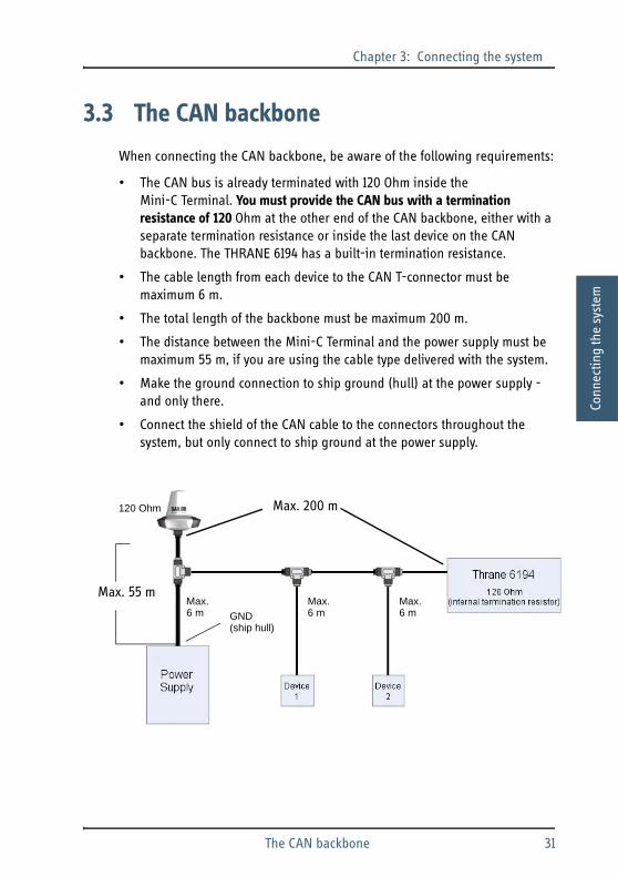
When connecting the CAN backbone, be aware of the following requirements:
• The CAN bus is already terminated with 120 Ohm inside the Mini-C Terminal. You must provide the CAN bus with a termination resistance of 120 Ohm at the other end of the CAN backbone, either with a separate termination resistance or inside the last device on the CAN backbone. The THRANE 6194 has a built-in termination resistance.
• The cable length from each device to the CAN T-connector must be maximum 6 m.
• The total length of the backbone must be maximum 200 m.
• The distance between the Mini-C Terminal and the power supply must be maximum 55 m, if you are using the cable type delivered with the system.
• Make the ground connection to ship ground (hull) at the power supply - and only there.
• Connect the shield of the CAN cable to the connectors throughout the system, but only connect to ship ground at the power supply.
Max.6 m
Max.6 m
Max.6 m
Max. 200 m120 Ohm
Max. 55 m
GND(ship hull)
The CAN backbone 31

Chapter 3: Connecting the system
3.4 Connecting power
3.4.1 Power source
• If you are connecting additional NMEA2000 equipment other than THRANE 6194 or SAILOR 6006 to the CAN bus, the power source for the Mini-C System must supply 15 V DC (nominal). To convert to 15 V DC you may use e.g. a SAILOR 6090 Power Converter or a SAILOR 6081 PSU and Charger. If you are not connecting any additional equipment to the CAN bus, the power range is 9 -32 V DC.
• The power source must be able to deliver sufficient power for the system units. Refer to Power requirements on page 13.
3.4.2 Connecting the power cables
SAILOR 3027
The SAILOR 3027 Mini-C Terminal has one CAN connector, which is also used for power input.
1. Connect the red wire to DC+ and the black wire to DC- in the power supply.
2. Connect the shield of the CAN cable to chassis on the power supply, which must be connected to ship ground. See Grounding the units on page 28.
Note If your power source is supplying more than 15 V, the system is not protected against incorrect wiring.
Caution! If your power source is a battery, you must configure an under-voltage protection for the battery. The battery may be damaged if the correct under-voltage protection is not applied! For details, see Under-voltage protection (UVP) on page 33.
32 Connecting power

Chapter 3: Connecting the system 33
33
Conn
ectin
g th
e sy
stem
THRANE 6194
The THRANE 6194, like the Mini-C Terminal, connects to power through the CAN interface, which in the THRANE 6194 is a group of spring-loaded terminals (X2). Refer to THRANE 6194 Terminal Control Unit, Installation and user manual [3].
Do not connect the shield of the CAN cable to the THRANE 6194.
3.4.3 Under-voltage protection (UVP)
If the power source is a battery, you must configure the Mini-C Terminal and the THRANE 6194 to the correct under-voltage protection.
Configure the under-voltage protection as follows:
1. Connect a computer to the THRANE 6194 and start a terminal program as described in Configuration using commands on page 54.
2. At the tt6194:/$ prompt, type in the relevant command depending on the voltage of the battery.
• Disable UVP: Type avr_uvp 0
• 24 V: Type avr_uvp 1
• 12 V: Type avr_uvp 2
• CAN voltage: Type avr_uvp 3
3. Type minic to access the Mini-C Terminal.
4. At the Can0:/$ prompt, type in the relevant command from step 2.
Caution! The battery may be damaged if the correct under-voltage protection is not applied!
Connecting power 33

Chapter 3: Connecting the system
3.4.4 Calculating power cables for the SAILOR 3027
If possible, use the cables included with your SAILOR 6120/30/40/50 system.
If you want to use other cables or extend the included cables, use the guidelines in this section to calculate the maximum length of your power cables.
Source impedance
The length of the power cable depends on the type of cable used and the source impedance of the ship’s DC power source.
The maximum allowed source impedance depends on the utilization of the power range of the DC input (9 - 32 V DC for the SAILOR 3027).
The total impedance is made up of the source impedance of the power supply plus the impedance of connected cables including connectors and joints where cables might be extended.
Calculating the maximum power cable length
To calculate the maximum cable length, do as follows:
1. If you are using the SAILOR 6081 PSU (source impedance ~ 0 Ohm) go to step 2. If you are using another DC power source or want to extend the included cable then measure the source impedance as shown in Measuring the ship source impedance on page 36.
2. Find the resistance per m for the cable type you are going to use.The table in the next page shows typical cable resistance - note that your cable type may differ from this. Refer to the data sheet for the cable you are using.
3. Calculate the maximum cable length as follows:
(supply voltage - 9 - (4 x source impedance)) x 0.125Max. cable length = cable impedance per meter
34 Connecting power

Chapter 3: Connecting the system 33
33
Conn
ectin
g th
e sy
stem
Max. cable length in m versus cable types, voltage and source impedance.
Important The max. cable length is 200 m if the cable is also carrying the communication interface and not just power.
Supply Voltage > 12 Volt 15 Volt 24 Volt
Source imp. in mOhm > 0 100 200 0 100 200 0 100 200
SizemOhm per m.
Cable length in metres
AWG 7 1,63 229 199 168 459 428 398 1147 1117 1086
AWG 8 2,06 182 158 133 364 340 315 910 885 861
AWG 9 2,60 144 125 106 289 269 250 721 702 683
AWG 10 3,28 114 99 84 229 214 198 572 557 542
AWG 11 4,13 91 79 67 182 169 157 454 442 430
AWG 12 5,21 72 62 53 144 134 125 360 350 341
AWG 13 6,57 57 49 42 114 107 99 285 278 270
AWG 14 8,29 45 39 33 91 84 78 226 220 214
AWG 15 10,45 36 31 26 72 67 62 179 175 170
AWG 16a
a. Device Net Mini
13,17 28 25 21 57 53 49 142 139 135
AWG 17 16,61 23 20 17 45 42 39 113 110 107
AWG 18b
b. Device Net Micro B type
20,95 18 16 13 36 33 31 89 87 85
AWG 19 26,42 14 12 10 28 26 25 71 69 67
AWG 20c
c. Device Net Micro A type
33,31 11 10 8 23 21 20 56 55 53
Connecting power 35

Chapter 3: Connecting the system
3.4.5 Measuring the ship source impedance
Without supplied cable
If you want to use another cable instead of the supplied cable, measure the source impedance without the cable as follows:
1. Measure the voltage without load (R.var disconnected).
2. Set the current to e.g. 1 A by adjusting R.var.
3. Measure the corresponding voltage change.
4. Calculate the source impedance from the voltage and the current.
Example: 1 A and 100 mV. Source impedance: 100 mV/1 Amp = 100 mOhm.
You can use this source impedance to calculate the maximum length of the cable between the power outlet and the Mini-C Terminal.
With the supplied cable
If you want to extend the supplied cable, measure the source impedance including the supplied cable, as follows:
1. Connect the supplied power cable to the DC power source.
2. Connect the other end of the power cable to the Mini part of the Mini/Micro T-connector.
Power outletfor terminal
36 Connecting power
Chapter 3: Connecting the system 33
33
Conn
ectin
g th
e sy
stem
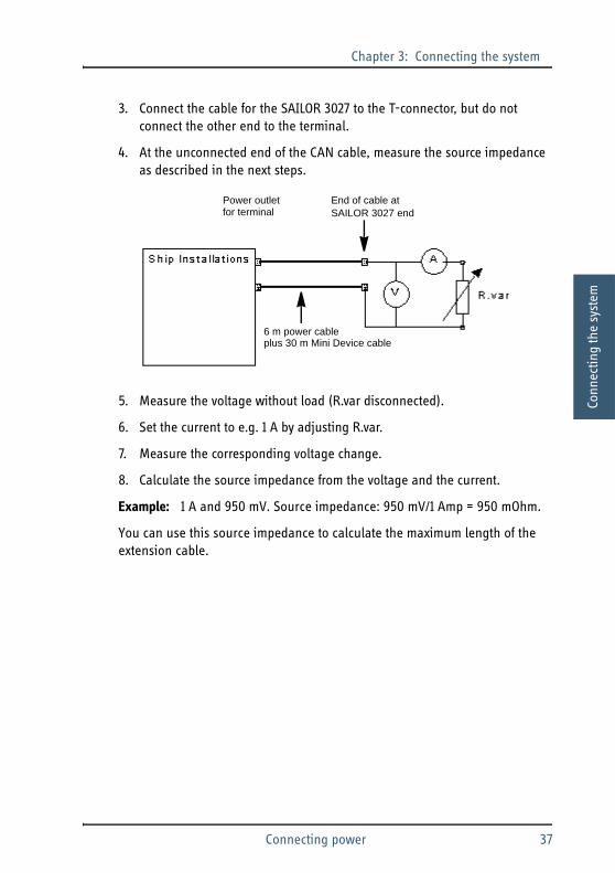
3. Connect the cable for the SAILOR 3027 to the T-connector, but do not connect the other end to the terminal.
4. At the unconnected end of the CAN cable, measure the source impedance as described in the next steps.
5. Measure the voltage without load (R.var disconnected).
6. Set the current to e.g. 1 A by adjusting R.var.
7. Measure the corresponding voltage change.
8. Calculate the source impedance from the voltage and the current.
Example: 1 A and 950 mV. Source impedance: 950 mV/1 Amp = 950 mOhm.
You can use this source impedance to calculate the maximum length of the extension cable.
Power outletfor terminal
End of cable at SAILOR 3027 end
6 m power cable plus 30 m Mini Device cable
Connecting power 37

Chapter 3: Connecting the system
3.5 Connectors and pin-out
3.5.1 SAILOR 3027 Mini-C Terminal
The Mini-C Terminal has one male CAN socket for connecting to power as well as communication interfaces. The table and drawing below show the pin-out for the connector.
In standalone systems, e.g. LRIT, where you do not use the communication interface, you only need to connect pin 2 and 3 to the power supply and the shield of the cable to ship ground at the power supply.
Important Secure the CAN cable at the Mini-C Terminal to avoid stressing the CAN connector and the housing of the terminal.
Pin Function Wire color
1 Not connected None
2 + Power Red
3 - Power Black
4 CAN H White
5 CAN L Blue
1
23
4
5
Front view on SAILOR 3027
38 Connectors and pin-out

Chapter 3: Connecting the system 33
33
Conn
ectin
g th
e sy
stem
3.5.2 SAILOR 6006 or 6007 Message Terminal
Overview
The drawing below shows the connector panel of the Message Terminal.
In the SAILOR 6150 system, the following connectors on the Message Terminal may be used:
• USB interface.Connects to a printer and a keyboard, or to a USB memory stick.
• Ethernet interface.Connects to the THRANE 6194 Terminal Control Unit or an Ethernet switch in a local network.
• ground stud.Connects to ship ground.
• CAN interface. Only used on SAILOR 6006 with the SAILOR 6150 System.Connects to the Mini-C Terminal and optionally other equipment using the CAN interface.
• DC Power input. Connects to the power supply.
The next sub-sections show the pin-out for these connectors.
For a complete description and pin-out for all connectors, see SAILOR 6006 and 6007 Message Terminal, Installation manual [2].
Ethernet DC PowerCANUSB
GND
Connectors and pin-out 39

Chapter 3: Connecting the system
USB interface
The USB connectors are USB Type A. The figure and table below show the connector outline, wire colours and pin assignments.
Ethernet
The figure and table below show the connector outline and pin assignments.
Pin number Pin function Wire color
1 5 V Red
2 D- White
3 D+ Green
4 GND Black
USB Type A socket
Pin number Pin function Wire color
1 Tx+ white/orange
2 Tx- orange
3 Rx+ white/green
4 Not connected blue
5 Not connected white/blue
6 Rx- green
7 Not connected white/brown
8 Not connected brown
RJ-45 female
40 Connectors and pin-out

Chapter 3: Connecting the system 33
33
Conn
ectin
g th
e sy
stem
X5, CAN interface (only used on SAILOR 6006 with SAILOR 6150 system)
The figure and table below show the connector outline and pin assignments.
X4, Power input
The figure and table below show the connector outline and pin assignments.
Pin number Pin function Wire color
1 Not connected None
2 CAN_S Red
3 CAN_C Black
4 CAN_H White
5 CAN_L Blue
M12 Panel screw connector5 pin male
Pin number Pin function
1 DC+
2 DC-
3 ON_IN
4 NC
Panel lock, 4 pin male
Connectors and pin-out 41

Chapter 3: Connecting the system
3.5.3 THRANE 6194 Terminal Control Unit
The drawing below shows the connectors on the THRANE 6194.
The THRANE 6194 Terminal Control Unit is used in the SAILOR 6120 SSA System for connecting SSA buttons, and may also be used in other systems for connecting additional equipment.
X5 and X6 are standard connectors for RS-232 (9-pin D-sub) and Ethernet (RJ-45), all other connectors are spring-loaded terminals.
X3 and X4 are for future use.
On the THRANE 6194, the following interfaces are used:
Note The THRANE 6194 is only included with the SAILOR 6120 SSA System, but can be acquired for other systems as well.
X5 X6
X1
X2
X3
X4
X7 X9 X11 X13
X14X12X10X8
42 Connectors and pin-out

Chapter 3: Connecting the system 33
33
Conn
ectin
g th
e sy
stem
• CAN spring-loaded terminals (X2).Connect to the CAN bus in the Mini-C System. This interface is also used for connecting power.
• Ethernet connector (X6).Connects to a computer, a SAILOR 6006 Message Terminal or an Ethernet switch.
• RS-232 connector (X5):Connects to a computer, e.g. for entering commands.
• Spring-loaded terminals X7 to X14: Connect to the SSA buttons, SAILOR 6108 Non-SOLAS Alarm Panel or monitoring equipment.
For further information, see THRANE 6194 Terminal Control Unit, Installation and user manual [3].
Important Do not connect the shield of the CAN cable on the THRANE 6194! The CAN shield must only be connected to ship ground at the power supply, in order to lead any lightning strike directly to ship ground and not to any user operated equipment.
Connectors and pin-out 43

Chapter 3: Connecting the system
44 Connectors and pin-out

Chapter 44
44
4
Conf
igur
atio
n
Configuration 4
This chapter explains the initial registration and configuration that may be necessary before using your Mini-C System. For further information on configuration and daily use of the system, refer to the user manual for the Mini-C System.
This chapter has the following sections:
• Registering your SAILOR 3027
• Configuration tools
• Configuration using easyMail
• Configuration using commands
Note For the SAILOR 6130 LRIT System: After installing the system an LRIT compliance test must be done according to the guidelines from the Flag administration under which the vessel is sailing.
45

Chapter 4: Configuration
4.1 Registering your SAILOR 3027
4.1.1 Service Activation Registration Form
Before using the SAILOR 3027 Mini-C Terminal on the Inmarsat C system you must register the terminal to the system.
Use the SARF (Service Activation Registration Form) supplied with the SAILOR 3027. A copy of page 1 of the SARF is shown in the next page. As a guide, some of the most important fields are filled in with red color. Note that the stated MES (Mobile Earth Station) model is just an example - the field must show the MES model you are registering.
The SARF for registration of Maritime MES (in this case the SAILOR 3027) can also be found on www.inmarsat.com/Support under Activation, including notes on how to complete the maritime form.
The Service Activation Registration Form contains different abbreviations that are explained here.
The SAILOR 3027 must be registered at either a PSA company or directly to the ISP. A PSA is a company handling the activation of Inmarsat mobiles and is short for Point of Service Activation. ISP is the company that provides the Inmarsat service and is short for Inmarsat Service Provider. In many cases the PSA and ISP is the same company that also operates a Land Earth Station (LES). The local PSA or ISP can be obtained by following the guidelines in the registration form.
The Service Activation Registration Form also includes information needed to find out how to pay the bill for the Inmarsat C service. This payment will be made directly to the Accounting Authority. In many cases the Accounting Authority (AA) is also the same company as the Inmarsat Service Provider (ISP).
In addition to the general information such as name and address, the ISN of the SAILOR 3027 must be specified. The ISN is found on the Delivery Note and on the label in the bottom of the SAILOR 3027 Mini-C Terminal.
Note In most cases the distributor registers the system for the customer.
46 Registering your SAILOR 3027

Chapter 4: Configuration 44
44
Conf
igur
atio
n
Registration for service activation of Maritime Mobile Earth Station PSA use only code Sections 1-4, 6 and 8 are to be completed by all customers Application number Tick Boxes as appropriate. Please write in block capitals Date Day Month Year Customer’s reference number Your name or the name of your organisation: Address: Town/city: State/province: Post/ZIP code: Country: Telephone + Country code ( ) Area code ( ) Telephone number ( ) Facsimile + Country Code ( ) Area code ( ) Facsimile number ( ) Email address: Contact person: Title: Department: What is their telephone number and/or extension? + Country code ( ) Area code ( ) Telephone number ( ) Note: ALL MARITIME MESs that are part of GMDSS installations MUST have an Accounting Authority as the billing entity, Apart from the FLEET F77 MES which may use either an ISP or an AA as the billing entity.
Is the MES part of a GMDSS installation? Yes No If YES, enter the Accounting Authority Code (AAIC): If Fleet F77 please see the Note above. If the Code is unknown, enter the name of the AA: If NO, have you arranged payment of calls for this MES through (tick one) (a) Accounting Authority (AA) (b) Inmarsat Service Provider (ISP) Enter ISP or AA Code: If the Code is unknown enter the name of the ISP or AA: NOTE: If the terminal is activated as Maritime Fixed and placed on a vessel, you could be Endangering Lives At Sea. Environment usage The System What will be the primary use of the MES? Maritime Inmarsat-B Trading Yachts Maritime Fixed Inmarsat-C/mini C Passenger/Cruise Other (IMO Number Mandatory) Inmarsat-M Offshore Other (IMO Number NOT Mandatory) Inmarsat mini-M Government please specify Inmarsat Fleet Fishing What will be the country of registry of this MES? Mobile Earth Station (MES) manufacturer Mobile Earth Station (MES) model
1.Your details (See note A) PLEASE NOTIFY YOUR PSA IF ANY OF THESE DETAILS CHANGE OR YOU ARE NO LONGER THE OWNER OF THE INMARSAT EQUIPMENT. (THIS IS A LEGAL REQUIREMENT AS STATED IN THE INMARSAT TERMS AND CONDITIONS WHICH ARE ATTACHED TO THE BACK OF THIS SARF)
2. Paying the bill (See note B) PLEASE NOTIFY YOUR PSA URGENTLY IF YOU CHANGE YOUR BILLING ENTITY (AA or ISP.) (THIS IS A LEGAL REQUIREMENT AS STATED IN THE INMARSAT TERMS AND CONDITIONS WHICH ARE ATTACHED TO THE SARF)
3. What type of Mobile Earth Station (MES) are you registering? (See note C)
Thrane & Thrane A/S SAILOR 3027 SSA Terminal
Registering your SAILOR 3027 47

Chapter 4: Configuration
4.1.2 Entering the mobile number in the SAILOR 3027
When the SAILOR 3027 Mini-C Terminal is registered at the ISP, the ISP returns a mobile number for the SAILOR 3027. This mobile number must be entered in the SAILOR 3027. You can use the easyMail application for this purpose. For details, see Configuration using easyMail on page 49.
4.2 Configuration tools
You may use one of the following tools for configuring your Mini-C System:
• Computer or SAILOR 6007 with easyMail application installed.You must have a THRANE 6194 Terminal Control Unit to connect your computer or SAILOR 6007 Message Terminal to the system. The easyMail application is delivered on CD with the THRANE 6194. Settings not available directly in the user interface can be accessed through the Terminal mode, where you can enter the same commands as with the terminal program (see below).
• Computer or SAILOR 6007 with terminal programYou must have a THRANE 6194 Terminal Control Unit to connect the computer or SAILOR 6007 Message Terminal to the system. For earlier version of Windows you can use Windows HyperTerminal, otherwise you can use telnet from the command line interface. The commands for configuration are available in SAILOR 3027 Software Interface Reference Manual [5].
• SAILOR 6006 Message Terminal.The SAILOR 6006 Message Terminal is available from Thrane & Thrane. With the SAILOR 6006 Message Terminal you can access several settings, without installing additional software. Settings not available directly in the user interface can be accessed through the Mini-C terminal mode in the Message Terminal, where you can enter the same commands as with the terminal program (see above).
48 Configuration tools

Chapter 4: Configuration 44
44
Conf
igur
atio
n
4.3 Configuration using easyMail
easyMail is a computer program, which can be used to control Thrane & Thrane and SAILOR Inmarsat-C terminals.
With easyMail you can send and receive e-mail, SMS, fax and telex messages, set up position reporting, receive EGC messages and more.
4.3.1 Installing easyMail
To be able to set up the Mini-C System using easyMail, you must first install the easyMail application on your computer as follows:
1. Insert the installation CD included with the THRANE 6194 into the CD drive of the computer. If you are using the SAILOR 6007 you may have the program on a USB memory stick.The setup program should start up automatically. If not, run the file setup.exe from the CD drive/USB memory stick.
2. Click Install easyMail and go through the InstallShield Wizard.
3. When the Wizard is complete, you can start the application from the easyMail shortcut on the desktop, or from Start > Programs > easyMail <version>.
4.3.2 Setting up PC communication with the Mini-C Terminal
To connect a computer or a SAILOR 6007 Message Terminal to the system you must use a THRANE 6194 Terminal Control Unit. You can connect to the LAN interface or the RS-232 interface on the THRANE 6194. If you are using SAILOR 6007, only LAN is available.
Note The COM settings in easyMail are not accessible when the computer has already established a connection with the Mini-C Terminal.
Configuration using easyMail 49

Chapter 4: Configuration
To set up LAN communication
To set up easyMail for LAN communication with the THRANE 6194 and thereby the Mini-C Terminal, do as follows:
1. Select Setup > Communication setup.
2. Select LAN communication.
3. Type in the IP address of the THRANE 6194 Terminal Control Unit (TCU).You can find the IP address in two ways:
• Using the SNMP upload program, described in Updating software on page 63.
• By pressing the Temporary fixed IP address button on the THRANE 6194. The IP address of the THRANE 6194 is temporarily set to 169.254.100.100.
Your IP: Shows the IP address of your PC. Make sure your PC is on the same subnet as the TCU! This means the two first sections of the IP address (10.6. in the example picture above) must be the same on the TCU as on your PC.
Same subnet
50 Configuration using easyMail

Chapter 4: Configuration 44
44
Conf
igur
atio
n
4. If you want to set the THRANE 6194 to a fixed IP address for your next easyMail session, select Force fixed IP and type in the IP address you want to use.
5. Click OK.easyMail now tries to establish a connection to the THRANE 6194 and thereby the Mini-C Terminal. When the LAN connection is established the PC connection bar at the top of the easyMail window turns green.
To set up RS-232 communication
To set up easyMail for RS-232 communication with the THRANE 6194 and thereby the Mini-C Terminal, do as follows:
1. Select Setup > Communication setup.
2. Select Serial communication.
3. Select the COM port you are using on your computer and the Baud rate of the THRANE 6194 (default is 115200).
4. Click OK.
Important Before clicking OK, make sure the IP address of your PC is on the same subnet as the new TCU IP address.
Configuration using easyMail 51

Chapter 4: Configuration
easyMail now tries to establish a connection to the THRANE 6194 and thereby the Mini-C Terminal. When the RS-232 connection is established the PC connection bar at the top of the easyMail window turns green.
4.3.3 Initial configuration
Before you can use the system, you must:
• Configure mobile number
• Log into an Ocean Region
• Configure default LES and E-mail Service Provider for sending messages.
Do as follows:
1. Start the easyMail application.
2. Select Setup > Mobile number.
3. Type in the mobile number (9 digits) and click OK.You should now see the mobile number in the status field at the top of the page.
4. Select Actions > Login and select the Ocean region that matches your current position.After a short while you should see the Ocean region just below the mobile number in the status field at the top of the page. This means you are now logged on.
5. Select Setup > Default ISP...
6. Choose your Inmarsat Service Provider from the list.
7. Select Setup > Default LES.
8. Choose the Land Earth Stations of your Inmarsat Service Provider for each Ocean region.
The system is now ready to send and receive messages.
52 Configuration using easyMail

Chapter 4: Configuration 44
44
Conf
igur
atio
n
4.3.4 Entering vessel data
You can enter vessel data that can be used for automatic insertion into your messages. To enter the data for your vessel, do as follows:
1. In the easyMail application, select Edit > Enter vessel data.
2. Enter name, type, flag, destination and cargo. You may also add a comment.
3. Click OK.You can now automatically insert all the above information in your message by selecting Insert > vessel data.
Configuration using easyMail 53

Chapter 4: Configuration
4.4 Configuration using commands
You can enter commands using one of the following tools:
• A computer or SAILOR 6007 with easyMail in Terminal mode
• A computer or SAILOR 6007 with terminal program or telnet.
All available commands, syntax etc. are described in the following documents:
• Mini-C Terminal setup: SAILOR 3027 Software Interface Reference Manual [5].
• THRANE 6194 setup: THRANE 6194 Software Interface Reference Manual [4].
The next sections describe the different methods for entering commands.
54 Configuration using commands

Chapter 4: Configuration 44
44
Conf
igur
atio
n
4.4.1 Computer with easyMail in terminal mode
To open the Terminal mode text editor in the easyMail application, do as follows:
1. From the menu bar in easyMail, select View > Terminal Mode.
A terminal window opens.
2. Type in your commands.
3. When you have finished, press Esc to exit and return to easyMail.
4.4.2 Computer with terminal program/telnet
To enter commands using a computer, you can use the serial RS-232 interface or the LAN interface.
Using serial RS-232 port
Do as follows:
1. Connect a computer to the RS-232 port of the THRANE 6194 Terminal Control Unit, which must be connected to your Mini-C System.Refer to the THRANE 6194 Terminal Control Unit, Installation and user manual [3] for information on how to connect and set up the interface.
2. On your computer start your terminal program.
3. Select the COM port you are using on your computer and select the port settings. The default baud rate for the THRANE 6194 is 115200.The terminal program should now establish a connection to the THRANE 6194.
4. If the prompt shows tt6194:/$, type minic to access the Mini-C Terminal.
Note The terminal window is now the only way to communicate with the Mini-C Terminal. No information is updated and no EGCs or messages are received until you exit the terminal mode.
Configuration using commands 55

Chapter 4: Configuration
When the window shows Connected, press Enter. The prompt should show Can0:/$.
5. Type in your commands.
Using LAN port
Do as follows:
1. Connect a computer or a SAILOR 6007 Message Terminal to the LAN port of the THRANE 6194 Terminal Control Unit, which must be connected to your Mini-C System.Refer to the THRANE 6194 Terminal Control Unit, Installation and user manual [3] for information on how to connect and set up the interface.
2. On your computer start your terminal program or start a telnet session.You can use the Thrane &Thrane SNMP upload application to find the IP address of the THRANE 6194. For details, see Updating the Mini-C Terminal software on page 64.
3. When the connection is established, if the prompt shows tt6194:/$, type minic to access the Mini-C Terminal.When the window shows Connected, press Enter. The prompt should now show Can0:/$.
4. Type in your commands.
56 Configuration using commands

Chapter 55
55
Inst
alla
tion
chec
k an
d te
st
Installation check and test 5
This chapter provides a check list to verify that the installation was made correctly, and shows how to make an initial test of the system.
This chapter has the following sections:
• Installation check list
• Testing the SAILOR 6130 LRIT System
• Testing the system with easyMail
Note The SAILOR 6120/30/40/50 system must be registered with the Service Activation Registration Form before you can test the system. Refer to Registering your SAILOR 3027 on page 46 for details.
57

Chapter 5: Installation check and test
5.1 Installation check list
After installing the SAILOR 6120/30/40/50 system, you can use the following check list to make sure you have installed the system correctly.
Important Make the installation check before applying power to the system!
Check item Reference OK
Is the Mini-C Terminal placed correctly?
No blocking objects Placing the SAILOR 3027 Mini-C Terminal on page 14Away from exhaust fumes
Minimum safety distance to people
Minimum distance to other equipment
Are all cables connected correctly?
Power cables Wiring overview on page 22 and Connecting power on page 32
CAN cables Wiring overview on page 22 and The CAN backbone on page 31
RS-232 cable (for PC, if connected) SAILOR 6120/30/40/50 with a computer on page 26Ethernet cable (for PC, if connected)
Do all cables meet the requirements in this manual?
58 Installation check list

Chapter 5: Installation check and test5
55
Inst
alla
tion
chec
k an
d te
st
5.2 Testing the SAILOR 6130 LRIT SystemIf you have a SAILOR 6130 LRIT System, you may not have anything connected to your Mini-C Terminal, except for a power supply.
However, we recommend testing the signal path. This can be done by requesting a LESO (LES Operator) in the Inmarsat-C system to perform a PVT (Performance Verification Test) on your SAILOR 3027 LRIT Terminal.
The LESO returns the result of the test, which is either that the mobile passed or failed the test. A written result may look like this:
Any further requirements for testing are defined by the Flag administration.
Power cables Cables and connectors on page 27
CAN cables
RS-232 cable (for PC, if connected)
Ethernet cable (for PC, if connected)
Is the shield of the CAN cable connected correctly to the ship ground (hull)?
SAILOR 3027 Mini-C Terminal on page 28
Is the polarity of power connections correct? Red wire = DC+ and Black wire = DC-
Connecting power on page 32
Check item Reference OK
Test Id Group Start time End time Overall result
pvt test ssm subsystem 20110128 15:07:45 20110128 15:17:07 finished pvt
Testing the SAILOR 6130 LRIT System 59

Chapter 5: Installation check and test
5.3 Testing the system with easyMail
5.3.1 Basic system verification
To verify the basic function of the system, connect a computer and start the easyMail application.
Then check the Mobile status field.
The field should show the Ocean region to which the Mini-C Terminal is logged in (Atlantic Ocean East in the picture above), and the bars for Antenna signal, GPS and PC connection should all be green.
The field may also look like this:
In this case, the PC has not established a connection to the Mini-C Terminal. If you are using RS-232, the reason may be that the COM port in the PC is already open by another application, or that the COM port or baud rate set in easyMail is incorrect. Close the other application or go to Setup > COM Settings and choose the correct port and baud rate (default 115200).
Below is an explanation of the bars.
• Antenna signalThis bar has 5 steps from all green to all red, depending on the quality of the satellite signal. Green: good signal quality. Red: no signal.
• GPSGreen: GPS OK. Red: GPS error or no antenna connection.
60 Testing the system with easyMail

Chapter 5: Installation check and test5
55
Inst
alla
tion
chec
k an
d te
st
• PC connectionGreen: easyMail has connected to the Mini-C Terminal. Red: No connection between easyMail and Mini-C Terminal.
5.3.2 Distress test (only SAILOR 6150 Non-SOLAS System)
To verify the connection to the SAILOR 6108 or SAILOR 3042E alarm panel, you can make a Distress test. Do as follows:
1. In the easyMail application, click Distress > Distress Test Mode. A popup shows that the system is in Distress test mode.
2. Press and hold the alert button on the SAILOR 6108 for at least 5 seconds.At first, the button light should be flashing, then it should be on with a short off-period every 15 seconds.
3. To clear alarm indications, select Distress > Reset alarms/latest Distress info, or press and then release the Clear button (if installed).The button light should go off.
4. To exit Distress test mode, click Cancel in the Distress test mode popup.
5.3.3 Link test
To test the satellite link between the Mini-C Terminal and the Land Earth Station you can make a link test.
Important Never test the installation by sending an alert on-air!
If an alert is sent by mistake, inform the relevant authorities immediately.
Important When you perform a link test, the system has limited functionality. The link test can take several minutes, because it has low priority in the network.
As an alternative, you can send a message to yourself to check the connection.
Testing the system with easyMail 61

Chapter 5: Installation check and test
To make a link test, do as follows:
1. In the easyMail application, click Actions > Link test.The test has 3 parts:
• Message reception
• Message transmission
• Distress test.
2. After the Link test is requested, the NCS assigns a LES for performing the Link test. This can take a short while.
3. When the Linktest window appears, click Execute to start the test.
A popup informs you that the test has started. When the test has ended another popup informs you that the test was completed successfully or that it failed.
Note The link test has low priority in the network, so it can take some time to get a connection.
62 Testing the system with easyMail

Chapter 66
66
Serv
ice
and
mai
nten
ance
Service and maintenance 6
This chapter describes how to maintain and handle the units in the system and how to update software. This chapter has the following sections:
• Updating software
• Maintenance guidelines
• Service and repair
• Available parts
6.1 Updating software
Required tools and files
Before you can update the software you must get a download tool and the new software for the Mini-C Terminal.
Do as follows:
1. Open your browser and log into the Thrane & Thrane Extranet.
2. Find and download the zip file containing the Thrane & Thrane SNMP upload application.
3. Extract the files to C:\Thrane (create the folder if it is not already there).Remember to select Use folder names.
4. On the Extranet, find the new software image for the Mini-C Terminal (.tiif file).
5. Download the .tiif file to the folder C:\Thrane\TFTP-Root (this folder should be created automatically when you extract the files from the zip file).
63

Chapter 6: Service and maintenance
Updating the Mini-C Terminal software
Get the download tool and the new software as described in the previous section. Then do as follows:
1. Connect the Mini-C Terminal to the THRANE 6194 Terminal Control Unit and connect your computer to the LAN port on the THRANE 6194.
2. Start the SNMP upload tool (.exe file) placed in C:\Thrane\.
3. The application searches for units connected to the local network. When a unit is found, it is listed with IP address, description, serial number and software version.
4. When the Mini-C Terminal appears in the list you can check the current software version in the sw-version column. If there are more than one Mini-C Terminal you can recognize your unit by the serial number.
5. Click on your Mini-C Terminal to select it.
6. When the IP address of your Mini-C Terminal appears in the small field in the bottom left corner, click the button Upload software (.TIIF file).
7. Browse to the .tiif file in C:\Thrane\TFTP-Root\.
8. Select the file and click Open.
Note It may take some time for the Mini-C Terminal to appear in the list.
64 Updating software

Chapter 6: Service and maintenance6
66
Serv
ice
and
mai
nten
ance
The software is now updated and the Mini-C Terminal automatically restarts with the new software. You can use the SNMP upload application again to check the software version as in step 4 above.
6.2 Maintenance guidelines
When properly installed the system needs no maintenance.
SAILOR 6006/6007 Message Terminal: The life time of the clock battery in the SAILOR 6006/6007 Message Terminal is 10 years. If the battery is no longer functional, the SAILOR 6006/6007 is not able to keep the correct time when power is disconnected.
The clock battery in the SAILOR 6006/6007 Message Terminal must be replaced by qualified personnel.
6.2.1 Handling precautions for SAILOR 3027
• Do not expose the joints of the SAILOR 3027 Mini-C Terminal or the connector to high-pressure water jets.
• Do not expose the connector on the terminal to mechanical stress. Secure the cable with cable relief.
• Do not expose the terminal to chemicals containing alkalis. It may result in physical degradation of the terminal.
• Do not expose the terminal to acid curing silicone.
• Avoid contact with solvents.
• Do not paint the terminal. It may result in degradation of the terminal.
Maintenance guidelines 65
Chapter 6: Service and maintenance
6.3 Service and repair
Should your Thrane & Thrane product fail, please contact your dealer or installer, or the nearest Thrane & Thrane partner. You will find the partner details on www.thrane.com where you also find the Thrane & Thrane Self Service Center web-portal, which may help you solving the problem.
Your dealer, installer or Thrane & Thrane partner will assist you whether the need is user training, technical support, arranging on-site repair or sending the product for repair.
Your dealer, installer or Thrane & Thrane partner will also take care of any warranty issue.
6.3.1 Repacking for shipment
Should you need to send the product for repair, please read the below information before packing the product.
The shipping cartons for the SAILOR 6120/30/40/50 system units have been carefully designed to protect the equipment during shipment. The cartons and their associated packing material should be used when repacking for shipment. Attach a tag indicating the type of service required, return address, model number and full serial number. Mark the carton “FRAGILE” to ensure careful handling.
Note Correct shipment is the customer’s own responsibility.
66 Service and repair

Chapter 6: Service and maintenance6
66
Serv
ice
and
mai
nten
ance
6.4 Available parts
6.4.1 Cables and connectors
Part number Item
406100-930 Mini/Micro NMEA 2000 T-Connector
406100-931 Micro NMEA 2000 T-Connector
406100-932 Inline Micro termination Connector
406100-933 Male Mini NMEA 2000 Field Connector
406100-934 Male Micro NMEA 2000 Field Connector
406100-940 6 m NMEA 2000 Micro Device Cable
406100-941 20 m NMEA 2000 Micro Device Cable
406100-942 50 m NMEA 2000 Micro Device Cable
406100-943 6 m NMEA 2000 Power Cable
406100-944 30 m NMEA 2000 Mini Device Cable
406100-945 50 m NMEA 2000 Mini Device Cable
406208A SAILOR 6208 Control Unit Connection Box
Available parts 67

Chapter 6: Service and maintenance
6.4.2 Adjustable pole/railing mount kit
Part number Item
403027-103 Adjustable pole/railing mount kit for SAILOR 3027
68 Available parts

Appendix AAAAA
Tech
nica
l spe
cific
atio
ns
Technical specifications AThis appendix holds the specifications for the SAILOR 6120/30/40/50 Mini-C System and the SAILOR 3027 Mini-C Terminal.
For specifications on the other units in the Mini-C System, refer to the installation manuals for the individual units.
A.1 SAILOR 6120/30/40/50 system specifications
For further information on compliance and certificates, refer to the Thrane & Thrane Extranet at http://extranet.thrane.com.
Item Specification
Compliance CE certified, R&TTE Directive
Inmarsat C type approved
69
Appendix A: Technical specifications
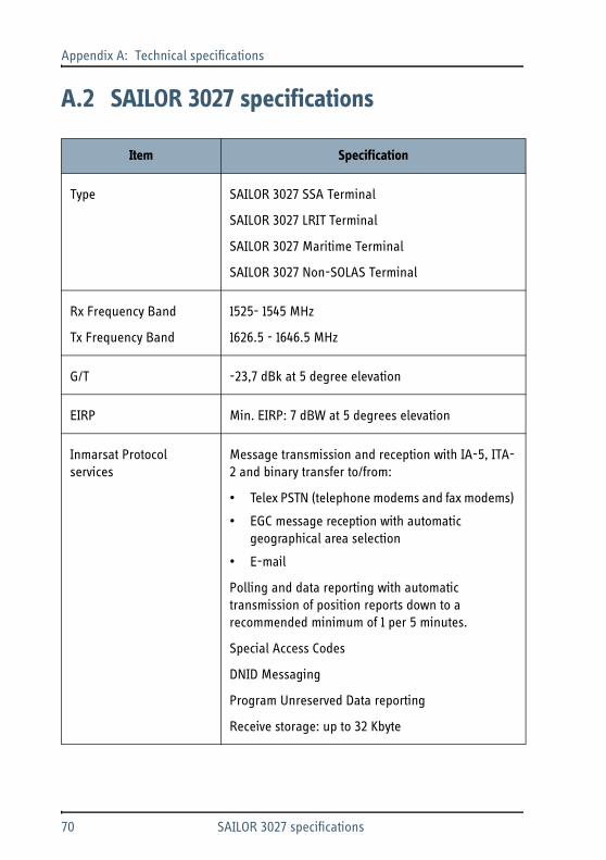
A.2 SAILOR 3027 specifications
Item Specification
Type SAILOR 3027 SSA Terminal
SAILOR 3027 LRIT Terminal
SAILOR 3027 Maritime Terminal
SAILOR 3027 Non-SOLAS Terminal
Rx Frequency Band
Tx Frequency Band
1525- 1545 MHz
1626.5 - 1646.5 MHz
G/T -23,7 dBk at 5 degree elevation
EIRP Min. EIRP: 7 dBW at 5 degrees elevation
Inmarsat Protocol services
Message transmission and reception with IA-5, ITA-2 and binary transfer to/from:
• Telex PSTN (telephone modems and fax modems)
• EGC message reception with automatic geographical area selection
Polling and data reporting with automatic transmission of position reports down to a recommended minimum of 1 per 5 minutes.
Special Access Codes
DNID Messaging
Program Unreserved Data reporting
Receive storage: up to 32 Kbyte
70 SAILOR 3027 specifications

Appendix A: Technical specificationsAAAA
Tech
nica
l spe
cific
atio
ns
Global services
Data: 1200 symbols/s BPSK.
Data rate: 600 bit/s
Max. Transmission size 10 Kbyte
Interface in SAILOR 3027 NMEA 2000 DeviceNet Mini-style, Male
Power input 9 V - 32 V DC.
15 V DC Nominal Input Power
Max. Power: 30 W
Max. continuous current: 2.8 A
Max. peak current: 4 A (startup)
Standby power, Rx mode < 2 W
Sleep Mode power < 10 mW
Compass safe distance 5 m
Weight 1.10 kg (without pole mount)
Dimensions Diameter: 170.5 mm, Height: 145 mm (without pole mount)
Water and dust IP66 and IP67
Ambient Temperature Operating range -35°C to 55°C
Storage -40°C to 80°C
Item Specification
SAILOR 3027 specifications 71

Appendix A: Technical specifications
Operation humidity 100%, condensing
Precipitation Up to 100 mm/hour, droplet size 0.5 to 4.5 mm
Ice, survival Up to 25 mm
Velocity Max velocity up to 140 km/hour (87 mph)
Wind Wind speed up to 200 km/hour (124 mph)
Vibrations, operational • Random 5-20 Hz: 0.005 g2/Hz
• 20-150 Hz: -3dB/oct. (0.5g RMS)
Vibrations, survival • Random 5-20 Hz: 0.05 g2/Hz
• 20-150 Hz: -3 dB/oct. (1.7 g RMS)
Shock Half sine 20 g/11 ms
Solar radiation Max. flux density 1200 W/m2
Equipment category IEC 60945 Environmental test
Item Specification
72 SAILOR 3027 specifications

GlossaryAAAA
Glossary A
Glos
sary
CCAN Controller–Area Network (CAN) is a message based protocol designed to allow microcontrollers and devices to communicate with each other within a vehicle without a host computer.
CE Conformitée Européenne. This term signifies that a CE certified product conforms to European health, environmental, and safety regulations. In short, it makes the product legal to be sold in the European Union.
D
DC Direct Current
DNID Data Network Identifier. An address code to an electronic mailbox at the Land Earth Station.
E
EGC Enhanced Group Call. A type of broadcast data for ships.
EIRP Effective Isotropically-Radiated Power. The amount of power that would have to be emitted by an isotropic antenna (that evenly distributes power in all directions) to produce the peak power density observed in the direction of maximum antenna gain.
G
GPS Global Positioning System. A system of satellites, computers, and receivers that is able to determine the latitude and longitude of a receiver on Earth by calculating the time difference for signals from different satellites to reach the receiver.
73

Glossary
H
HPA High Power Amplifier
I
IEC International Electrotechnical Commission. The international standards and conformity assessment body for all fields of electrotechnology.
IMSO International Maritime Satellite Organisation. An intergovernmental body established to ensure that Inmarsat continues to meet its public service obligations.
ISN Inmarsat Serial Number. A unique number assigned by a terminal manufacturer to each newly manufactured terminal for Inmarsat’s satellite networks.
ISP Inmarsat Service Provider. The company providing the Inmarsat services.
L
LAN Local Area Network. A computer network covering a small physical area, like a home, office, school or airport.
LES Land Earth Station
LESO LES Operator
LNA Low Noise Amplifier
LRIT Long Range Identification and Tracking. A system established by the IMO applying to all passenger ships, cargo ships > 300 gross tonnage and mobile offshore drilling units. These ships/units must automatically report their position to their Flag
74

GlossaryAAAA
Glos
sary
Administration at least 4 times a day. Other contracting governments may request information about vessels in which they have a legitimate interest under the regulation.
M
MES Mobile Earth Station. An Earth station in the mobile-satellite service intended to be used while in motion or during halts at unspecified points. The SAILOR 3027 is the MES in the SAILOR 6110 GMDSS system.
N
NMEA National Marine Electronics Association (standard). A combined electrical and data specification for communication between marine electronic devices such as echo sounder, sonars, anemometer (wind speed and direction), gyrocompass, autopilot, GPS receivers and many other types of instruments. It has been defined by, and is controlled by, the U.S.-based National Marine Electronics Association.
P
PSA Point of Service Activation. A company handling the activation of Inmarsat mobiles.
PSTN Public Switched Telephone Network. The network of the world’s public circuit-switched telephone networks. It consists of telephone lines, fibre-optic cables, microwave transmission links, cellular networks, communications satellites, and undersea telephone cables all inter-connected by switching centres which allows any telephone in the world to communicate with any other.
PVT Performance Verification Test
75

Glossary
R
R&TTE Radio and Telecommunications Terminal Equipment
S
SARF Service Activation Registration Form. A form used to register your mobile equipment for activation of the services you are going to use.
SSA Ship Security Alert. The ship security alert system is provided to a vessel for the purpose of transmitting a security alert to the shore (not to other vessel!) to indicate to a competent authority that the security of the ship is under threat or has been compromised.
U
USB Universal Serial Bus. A specification to establish communication between devices and a host controller (usually personal computers). USB is intended to replace many varieties of serial and parallel ports. USB can connect computer peripherals such as mice, keyboards, digital cameras, printers, personal media players, flash drives, and external hard drives.
UVP Under-Voltage Protection
76

IndexBB
B
Index BB
Inde
x
A
activation of service, 46
B
battery, under-voltage protection, 33
C
cablescalculating max length (power), 34table with max. lengths, 35
cables and connectorslist of, 27
CAN backbonedescription and requirements, 31
commandsusing, 54
configuration, 45tools for, 48with commands, 54with easyMail, 49
connectorsMessage Terminal, 39SAILOR 3027, 38SAILOR 6006, 39THRANE 6194, 42
D
distancecompass, 14safety, 14to other equipment, 14
document numberthis manual, i
documents, related, v
E
easyMailconfiguration with, 49installing, 49using LAN, 50using RS-232, 51
H
handling, 65
I
initial inspection, 11installing easyMail, 49
L
LANsetup with easyMail, 50
line of sight, 14
M
maintenance, 65manual
document number, imanuals, related, vMessage Terminal
description, 8Message Terminal, connectors, 39mobile number
entering (easyMail), 52
77

Index
mounting the SAILOR 3027, 20
O
overview of system, 2
P
pin-outMessage Terminal, 39SAILOR 3027, 38SAILOR 6006, 39THRANE 6194, 42
pole mount, 17power cable
calculating max. length, 34table with max. lengths, 35
power consumption, 13power requirements, 13
R
registration, 46repacking for shipment, 66returning units, 66RS-232
communication with easyMail, 51
S
safety distance, SAILOR 3027, 14safety summary, iii
78
SAILOR 3027connector and pin-out, 38description, 6mounting on flat surface, 20mounting on pole, 17placing, 14specifications, 70
SAILOR 6006connectors and pin-out, 39
SAILOR 6007description, 8
serial communication with easyMail, 51service activation, 46shipment
repacking, 66specifications
SAILOR 3027, 70system, 69
system overview, 2system specifications, 69
T
THRANE 6194, connectors, 42tools for configuration, 48typography used in this manual, vi
U
under-voltage protection, 33user interface, 48
W
warranty, 66wiring of the units, 22

