sal 35 - nad klima · sal 35 ® 1 presentation and bene˜ts areas of application - rooms with...
TRANSCRIPT
D A L 3 5 8®
SAL35Linear diffuser
c a t a l o g 1 . 1 . 3
®
MADE IN
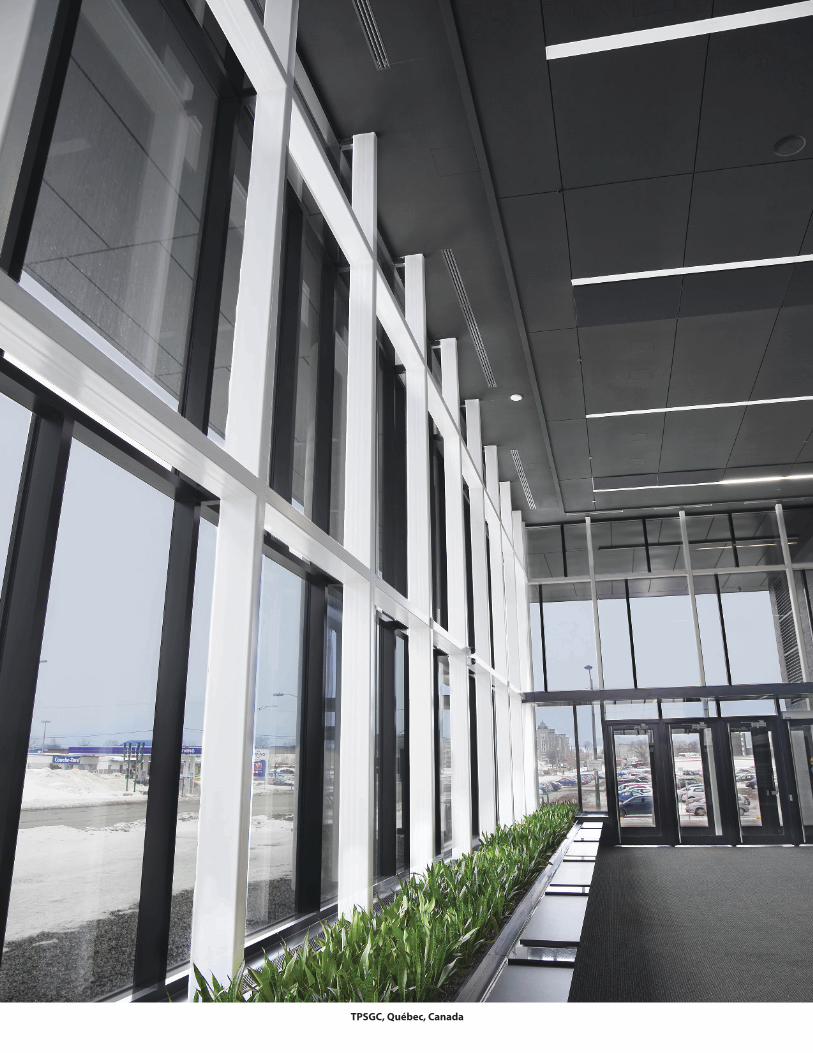
TPSGC, Québec, Canada

S A L 3 5®
Description, areas of application and bene�ts . . . . . . . . . . . . . . . . 1
Con�guration and mode of operation . . . . . . . . . . . . . . . . . . . . . . . . 2
Direction of the air �ow . . . . . . . . . . . . . . . . . . . . . . . . . . . . . . . . . . . . . . 3
Selection of the number of slots
- Di�user with eccentric rollers . . . . . . . . . . . . . . . . . . . . . . . . . . . . 4
- Di�user with nozzle rollers . . . . . . . . . . . . . . . . . . . . . . . . . . . . . . 5
Diagrams of air �ow velocity and loss of pressure
- Di�user with eccentric rollers . . . . . . . . . . . . . . . . . . . . . . . . . . . . 6
- Di�user with nozzle rollers . . . . . . . . . . . . . . . . . . . . . . . . . . . . . . 7
-Acoustic power level . . . . . . . . . . . . . . . . . . . . . . . . . . . . . . . . . . . . 8
Dimensions
- Dimensions of pro�le and installation . . . . . . . . . . . . . . . . . . . . 10
- Dimensions of di�user with plenum . . . . . . . . . . . . . . . . . . . . . . 11
- Total length with end cap . . . . . . . . . . . . . . . . . . . . . . . . . . . . . . . . 14
End cap and connectors. . . . . . . . . . . . . . . . . . . . . . . . . . . . . . . . . . . . . 15
Speci�cations. . . . . . . . . . . . . . . . . . . . . . . . . . . . . . . . . . . . . . . . . . . . . . . . 16
Codi�cation . . . . . . . . . . . . . . . . . . . . . . . . . . . . . . . . . . . . . . . . . . . . . . . . . 17
Table of content
© NAD Klima 2019 - All rights reservedSAL 35® and NAD Klima® are registred trademarks, operated under licenses by Equipement NAD inc.
The information contained in this catologue is subject to change.Refer to the digital version on www. nadklima.com
Version 2019

University of Québec, Rimouski, Canada

S A L 3 5®
1
Presentation and b ene�ts
Areas of application- Rooms with average ceiling heights- Situations where the di�user must adapt to the contours
and colours of the room- O�ces with partitioned workspaces- Clean rooms- Call centres- Closed o�ces- Computer (server) rooms- Meeting rooms- Multi-purpose rooms- Systems with constant or variable air�ow rates- Entrance halls (vertical air streams)- Fenestrated walls- Theaters
Bene�ts- In�uence on the method of induction (di�use
mode), extension of jets (divergent mode) and a very long vertical stream in heating mode (diver-gent nozzle rollers)
- Rapid reduction of �ow speed and temperature variations caused by high induction
- Low acoustic power for high air�ow rates- Stable laminar air�ow and a variety of air�ow
directions available - Eccentric rollers allowing 180° air�ow adjustment- Possibility of adjusting air�ows, even after installa-
tion- Possibility of reducing total air�ow rate as much as
25% in VAV- Approximately 3 times more induction than a
conventional linear di�user- Approximately 3 times less temperature variation in
occupied area than a traditionnal di�user- Possibility of eliminating external heating sources
due to the di�user‘s heating abilities- Adaptable to systems requiring constant or variable
air�ows- Areas with high air movement and low air velocity in
the occupied zone
The SAL 35 di�user is composed of extruded aluminum surfaces with eccentric rollers, which slide inside and are mounted on the plenum, as well as linear slots with 35 mm pro�les. Each di�user is supplied with a stabilising chamber, allowing for a uniform and silent air�ow.
The SAL 35 is available with one or multiple slots, depending on the application and required amount of air. The di�users can be installed in series, one behind the other, creating a continuous e�ect to the ceiling.
The SAL enables optimal con�guration of the ventilation system to meet a room’s require-ments. Due to the eccentric rollers, a variety of airstream con�gurations can be achieved, even after the unit has been installed.
The SAL 35’s technology provides high speed discharge of air with low acoustic power.
The laminar �ow, the stability and the high induction generated from the very start of the outlet vent make the SAL the linear di�user of
choice for high air �ow rates and variable air volumes.

S A L 3 5®
Con�guration and mo de of op eration
2
Con�guration
The SAL linear di�user slots are composed of extruded aluminum (1) with additional wide or narrow �nishing pro�les (2), eccentric rollers (3), which can rotate on 360 degrees and a plenum (4).
The 100 mm long eccentric rollers (3) o�er a low acoustic level and optimal aerodynamics. They possess on their axis multiple air guiding planes (5), a display and adjustment dial (6) on which are alphanumeric characters, allowing the user to de�ne and reproduce the roller settings.
The nozzle roller is the same dimension as the eccentric roller, with a larger e�ective surface. It is designed for application in locations with high ceilings.
The pro�les are attached to the plenum with screws for suspended ceilings and with central screws for gypsum ceilings.
The di�user is powder coated with a polyester TGIC-free paint, providing a smooth, easy-to-clean, chip and fade resistant �nish. The colours are available from the RAL colour chart.
Indexing- range
Mode of operation
The eccentric rollers and nozzle rollers form, combined with aluminum air guiding slots, an optimal air �ow.
A drop in pressure occurs when approching the surface of the rollers. As the air leaves the slot, it is stable and generates a low level of acoustic power. The �ow maintains a powerful induction of ambient air.
The positioning of the eccentric rollers allows an adjustment of the air jet’s direction, with or without reduction in the exit area.
Rollers have small plates to guide the air, which support a dense air�ow and maintain the air �ow direction perpen-dicular to the rollers’ axis.
Adjustment of the air jet direction
Thanks to the shape of eccentric rollers and adjustment dial with alphanumer-ic characters, the direction of the air jet at the di�user’s outlet can vary up to 180°. For each direction, there are two (2) roller positions (“reduced” or “not reduced”), as illustrated in �gure B.
For a ceiling installation, a horizontal air�ow is generated by the Coanda e�ect, with the rollers in positions EF, F6, 1A, AB and 21, 32, 54 and 65. The length of the rollers is adjustable up to 100 mm.
As a result, the combinations of air�ow are almost in�nite. During manufactur-ing, rollers are normally set alternately in position 21 and 65 (di�usion mode). This setting produces a strong induction �ow, which is e�ective even in high cooling needs and mixed air rates.
The nozzle roller can only be set in open and closed positions.
Operation
Volume �ow
Direction of air �ow
Figure BFigure A Figure C
C/D
4/3
B/C
A/B
1/A
3/22/1
D/E
E/F
F/6
6/55/4
A
BC D
EF
612
3 45
min. max.
Note : Codi�cation is
facing air stream
Roller nozzle Eccentric roller
1 Extruded aluminum pro�le2 Wide or narrow �nishing pro�le3 Eccentric rollers4 Plenum5 Air guiding blades6 Display and adjustment dial.

S A L 3 5®
3
D irec tion of air �ow
Controlling the direction of air�ow
The diagrams below illustrate the di�erent relationships between the position of the eccentric rollers and the air jet’s direction at the roller’s outlet.
Notes : The adjustable side of the roller must be to the left of the collar. During assembly, the NAD label is placed on the same side as the collar of the plenum.
When the air inlet is on the top or a wall installation, follow the directions on the workshop design.
Examples of application
max
. 3 m
(10
ft)
1.8 m(6 ft)
BC / 65Di�useDFL
BC / 65 Di�use
DFL
21 / 65 Di�use
DFS
1.8 m(6 ft)
CD / AB Di�useDFN
CD / EFDi�use
DFT
L
min. max.Rollers at 21
4.5
m -
9 m
(15-
30 ft
)
1.8 m(6 ft)
DRB(with roller nozzle)
DRB(with roller nozzle)
BC / DE Di�use
DFH
Air inlet collar
Air inlet collar
Rollers at 65
3 m
- 4.
5 m
(10-
15 ft
)1.8 m(6 ft)
CD DivergentDVV
CDDivergent
DVV
BC / DE Di�use
DFH
IndexingRange
Volume Flow
Air jet on one side

S A L 3 5®
4
S elec tion of numb er of s lotwith eccentric rol lers
Congress Center, Drummondville, Canada
1000 (180)
)
900 (161)
800 (144)
700 (126)
600 (108)
500 (90)
400 (72)
300 (54)
200 (36)
100 (18) 120 (22)
240 (44)
450 (81)
600 (108) 600 (110)
720 (132)
840 (154)
1 2 3 4 5 6 7 8
1
2
1000 (
1971100 (
)2151200 (
900 (
800 (
700 (
600 (
500 (
400 (
300 (
200 (
100 (
140 (25)
100 (18)
120 (22)
85 (15)
240 (43)
200 (36)
280 (50)
170 (30)
360 (65)
300 (54)
420 (75)
255 (46)
480 (86)
400 (72)
500 (90)
560(100)
340 (61)
425 (76)
600 (108)
700 (126)
600 (108)
720 (129)700 (126)
510 (91)
595 (107)
680 (122)
800 (144)
1120 (201)
960 (172)
840 (151) 840 (151)
980 (176)
V.
[m / h
/m
(c
fm/li
.ft)
Air
�ow
V.
[m / h
/m]
number of slots (n)
. m3/h/m / slot (cfm/ li.ft / slot)
85 - 120 (15 - 22)
Heating and cooling or heating only for heights of 3.0 m (10 ft) - 4.3 m (14 ft) 100 - 140 (18 - 25)
Cooling only for all ceiling heights
Heating and cooling or cooling only for ceiling heights ≤ 3.0 m (10 ft)
- In the case where heating mode can not be selected with initial air �ow, reduce the length Ls of the slot in accordance with the air �ow per meter of slot recommended.- In critical acoustic environment, increase the number of slots.
Air Flow by meter of slot of SAL 35 V0
Note:
2
1
To facilitate the selection of the SAL, total air�ow must be calculated for active slot lengths of 1 m.
Speci�cations:Height of the air-duct: H = 2.74 m (9 ft)Air�ow by di�user: Vo = 384 m3/hCooling: ∆T = - 15°CHeating: ∆T = +15°CLength of SAL: L = 1500 mm
Required:1- Air�ow by meter of slot section2- Number of slots n in cooling
Solution: Each slot of 1500 mm = 1.5 m of length, which we divide by 1.5 to �nd the air �ow by meter of slot: 324 m3/h/1.5 = 256 m3/h/m
From the diagram “Number of slots” and in a cooling mode, we �nd the number of slots: n = 3.
For an installation heightup to 4.3 m (14 ft)
.

S A L 3 5®
S elec tion of numb er of s lotswith rol ler nozzle
5
Note:
2
1
To facilitate the selection of the SAL 35, total air�ow must be calculated for active slot lengths of 1 m.
Speci�cations:Height of the air-duct: H = 5.00 mAir�ow by di�user: Vo = 770 m3/hCooling: ∆T = - 15°CHeating: ∆T = +15°CLength of SAL: L = 1500 mm
Required:1- Air�ow by meter of slot section2- Number of slots (n) in cooling
Solution: Each slot of 1500 mm = 1.5 m of length, which we divide by 1.5 to �nd the air �ow by meter of slot: 770 m3/h / 1.5 = 513 m3/h/m
From the diagram “Number of slots” and in a cooling mode, we �nd the number of slots: n = 2.
.
- In the case where heating mode can not be selected with initial air �ow, reduce the length Ls of the slot in accordance with the air �ow per meter of slot recommended.- In critical acoustic environment, increase the number of slots.
For an installation height from4.3 m (14 ft) to 9 m (30 ft)
Heating only for ceiling heights of 4.3 m (14 ft) - 6.1 m (20 ft) 240 - 325 (42 - 57)
Heating only for ceiling heights of 6.1 m (20 ft) - 9 m (30 ft) 290 - 375 (51 - 66)
.Air Flow by meter of slot of the SAL 35 V0
m3/h/m/slot(cfm/li.ft/slot)
Air
�ow
V.
(m
/ h/m
(
cfm
/li. f
t) V
.
/ h/m
)
1
1400 ( )
1200 ( )
1000 (180)
800 (144)
600 (108)
400 ( 240 (44)
600 (108)
1050 (189)
1 2 3 4 5 6 7 8
1
251
287
215
1000 ( )
800 (144)
108
72)
200 ( )36
325 (58)
650 (117)
580 (104)
290 (52)
1600 ( )
3231800 ( 3 )
3592000 ( )
3942200 ( )
4302400 ( )
4662600 ( )
5022800 ( )
3000 ( )
240 (43)
480 (86)
2
720(129)
870(156)960(172)
1300(233)
1200(215)
1500(269)
1625(291)
1875(336)
1450(260)
1440(258)
1950(350)
2275(408)2250
(403)
1740(312)
2625(471)
1680(301)
2030(364)
1920(344)
2600(466)
3000(538)
2320(416)
375 (67)
750 (134)
975(175)
1125(202) 1160
(208)
538
.

S A L 3 5®
30
40
60 50
D iagrams of air �ow velo cit y and loss of pressure with eccentric rol lers
6
Roller position
1 x 1A / 1x F6Standard
All CD
V max= V max Diagram *k
All 1A orAll F6
y
x x x
,
y max
Vertical : all CD
Air�ow velocity
v max
Air�ow distance after meeting y
xcrit
Air�
ow d
ista
nce
x, w
ith 1
A, F
6 (d
i�us
e)
Air�
ow d
ista
nce
with
CD
Air�
ow d
ista
nce
with
1 A
, F 6
(di�
use)
3
2
4
6.6 4.9 3.3 1.6
32.8
26.2
19.7
16.4
13.1
9.8
8.2
6.6
4.9
3.3
2.6
2.01.6
y m
ax
6.6
4.9
3.9
3.3
2.6
2.0
1.6
1.3
X cr
it
32.8
26.2
19.716.4
13.1
9.8
6.6
For an installation heightup to 4.3 m (14 ft)
mft
mftm ft
6
± 20˚C 68˚F
± 20˚C 36˚F± 12˚C 22˚F
± 15˚C 27˚F± 10˚C 18˚F± 8˚C 15˚F± 6˚C 11˚F± 4˚C 8˚F
5
k = 1.0
k = 2.0
k = 1.6
1 x 1A / 1 x F6
Num
ber o
f slo
ts
1
Air �ow V·
m3/h/m slotcfm/li. ft/slot
see example on page 4
7 9 11 13 14 16 18 22 27
Pressure drop ∆pt
In./H2OPa
0.02 0.024 0.01 4 5 6
0.03 9
0.05 12
0.06 15
0.09 23
0.13 32
0.2 50
7
80 ppm
100
120
140
160

S A L 3 5®
D iagrams of air �ow velo cit y and loss of pressurewith rol lers nozzle
7
∆T = + 10 °C 18°F
+ 20 °C 36°F
Temperature di�erence
+ 8 °C 15°F
+ 15 °C 27°F
4,0
4,5
5,0
5,5
6,0
6,5
7,0
7,5
8,0
y0.25 m/sy0.5 m/s
+ 6 °C 11°F
+ 4 °C 8 °F
50 fpm100 fpm
∆T = - 4 °C 8 °F
0
- 6 °C 11 °F - 10 °C 18 °F
- 8 °C 15 °F - 15 °C 27 °F
0
1,5
1,0
2,0
2,5
3,0
3,5
4,0
4,5
5,0
5,5
6,0
3,7
7,08,0
(30 fpm)
0,15 m/s (50)
0,25
(100)
0,5
(150)
0,75
(300)
1,5
(600)
3,0
max
(400)
2,0
(200)
1,0
(75)
0,37
(120)
0,6
(700)
3,5
(1000)
5,0
19.7
23
12.1
18
16.4
14.8
13.1
11.5
9,8
8.2
6.6
5
3.3
26.3
5,317.4
26.3
24.6
23.0
21.3
20.0
18.0
16.4
14.8
13.1
9,5
8,0
7,5
7,0
6,5
6,0
5,5
9,0
8,5
6,9
6,3
5,9
5,3
4,8
4,4
7,9
8,57,4
20.0
23,0
24.6
26.3
28.0
29.5
31.2
21.317.4
15.7
19.4
20.7
22.6
24.3
26.0
28.0
18.014.4
3,5 11.5
y
y 0.5
m/s
y 0.25
m/s
y ma
x
Isot
herm
al a
ir �o
w d
ista
nce
y
Air �ow velocity V =
For an installation height from4.3 m (14 ft) to 9 m (30 ft)
mft
Vert
ical
pen
etra
tion
on c
oolin
g
Vert
ical
pen
etra
tion
on h
eatin
g
y max
y
mft mft m ft
Num
ber o
f slo
t
1
2
256170 200 350 450 500 550 600400
Air �ow V̇
m /h/m slotcfm/pi li./slot 30 36 54 63 71 80 90 97 106 115 125 130
See example on page 5
50 300 650 700 750
Pressure drop ∆pt
In / H2OPa
0.2 50
0.25 62
0.23 57
0.27 67
0.02 0.04 0.1 0.12 0.13 0.16 5 10 25 30 32 40
0.3 75
0.33 82

S A L 3 5®
8
L WA (d
B(A)) -
Eccentric ro
ller
Noi
se C
riter
ia N
C -
SAL
35 w
ith e
ccen
tric
rolle
r (w
ith ro
om’s
abso
rptio
n of
10
dB)
9
1
8exemple
Air �ow V·
m3/h/m slotcfm/li. ft/slot 9 11 13 14 18 22 25 29
Number of slotk (dB)
1 2 3 4 5 6 7 8 9 100.0 3.0 4.7 6.0 7.0 7.8 8.4 9.0 9.5 10.0
Eccentric rollersNC diagram + 0 3 7 10 13 17 20 24 27 30Nozzle rollersNC diagram + 0 5 8 11 15 19 24 27 30 34
30
25
15
20
Air �ow V· m3/h/m slot
cfm/li. ft/slot200 450 500 60040036 54 71 80 90 95 106 115 125
300 650 700
Noi
se C
riter
ia N
C -
SAL
35 w
ith n
ozzl
e ro
ller (
with
room
’s ab
sorp
tion
of 1
0 dB
)
40
30
15
20
45
25
50
55
550
3516
18
3 slots each: SAL 35 - 1500 - 33/h
- Cooling mode: ∆T = - 15 °C- Heating mode: ∆T = + 15 °C- Width of space: 4 m- Length of space: 8 m- Height of space: 2.74 m- Head height: 1.8 m
Required:
zone Vmax 3. Critical distance in cooling mode Xcrit
5. NC value and acoustic power LWA
4. Loss of pressure ∆P t
Solution:3/h and 4
1535 x 4 = 384 m 3
We divide by the number of slots: 384 m3/h ÷ 3 = 128 m3/h. Each slot of 1500 mm = 1.5 m in
128 m3/h ÷1.5 = 85 m3/h/m 2. From the sizing diagram, a wall
distance x = 2 m and a trajectory after they meet y = 3 m – 1.8 m = 1.2 m,
in the occupied zone of: Vmax = 0.25 m/s
3. For the cooling mode of -15°C, we can determine the critical distance Xcrit = 8.5 m
5. The NC Value and acoustic power for air�ow per meter of slot of 85 m3/h/m
are: LWA diagram = 28 dB(A)
From the values shown in the table we calculate: NC diagram = 13 +7 = 22 LWA = LWA diagram + I = 28 + 4.7 + 7.8 = 40.5 dB(A)
40.5 dB(A) - 10 dB(A) = 30.5 dB(A)
slot we read: ∆Pt = 13 Pa 4. For an air�ow by meter of 85 m3/h/m
1
5
2
4
7
6
3
Important : The absorption of the room is not accounted for.For a comparison with north american values, reduce the acoustic power by 10 dB.
1.5 m
1.5 m
1.5 m
1.5 m
1
2
3
4
5
6
7
8
9
10
0.0
3.0
4.7
6.0
7.0
7.8
8.4
9.0
9.5
10.0
Length of dB(A)
Acoustic p ower level
�ow per meter of slot:
The length of di�usion: 1.5 m (5 ft) The length of di�usion: 4.5 m (15 ft)
98
NC diagram < 15
Nozzle roller
Eccentric roller

Mississauga University, Mississauga, Canada

S A L 3 5®
10
Ø D
H
Ø D
14
H
14
Screw to �xthe di�user
Gypse 5/8”
.
32
32
35
32
58
32
65
91
65
65
68
65
58
AB
C D E
F6
1
2 3 4
5
A
BC D
EF
612
3 45
Gypse
44 44
4444
The balancing key (optional) is adjustable per the di�user.Position and �x the plenum. Ensure the inlet opening of the di�user is leveled with the ceiling, simply by pressing on the di�users inlet.
Attach with the screws provided for this purpose. Suspension of the plenum is achieved with hooks and a threaded rod (not included).
Mounting and suspension for a gypsum ceiling
Spring balancing damper(optional)
Opening in the gypsum
The SAL 35 is fabricated with wide or narrow di�user slots made of extruded aluminum surfaces with eccentric rollers.
The di�user is also available with a custom made steel plate (p.15).
Available dimensions are300, 400, 500, 600, 700, 800, 900, 1000, 1100, 1200, 1300, 1400, 1500, 1600, 1700, 1800, 1900, 2000 mm.Intermediate dimensions are also available.
A combination of multiple standard lengths allows the creation of a di�user of the desired length. Two pins ensure an invisible connection between di�users.
D imensions of pro�le and instal lation
One slot SAL 35 pro�le with narrow pro�le
One slot SAL 35 pro�le with wide pro�le
Two slots SAL 35 pro�le with narrow pro�le
Two slots SAL 35 pro�le with wide pro�le

S A L 3 5®
11
D imensions of di�user and plenums
SAL 35, 1 slot SAL 35, 2 slots SAL 35, 3 slots and more
Perforated platePerforated plate
Perforated plate
H
B
E
FH
BH
14
14
14
PS (with narrow pro�le)PL (with wide pro�le)
50 50 50
9158
PS (with narrow pro�le)
PL (with wide pro�le)
GrillagePerforated plate
Ø D
H
B
E
F
Ø D
14
14
58 90.5
B
Ø D
14
D D D
SAL 35, 1 slot SAL 35, 2 slots SAL 35, 3 slots and more
H
H
Di�user and plenum with side round inlet
Spring Balancing Damper
(optional)
Radial Damper
(optional)
Note: The measurements are indicated in the table on pages 12 and 13.
Note: The measurements are indicated in the table on pages 12 and 13.
Di�user and plenum with top inlet

S A L 3 5®
D imensions of di�user and plenumEccentric rol lers
12
from 300 to 600
120
342
58
65
69
91
150
150 (oval)
1
from 650to 900
120
342
58
65
69
91
200
200 (oval)
1
from 950to 1500
120
342
58
65
69
91
200
200 (oval)
1
from 1550to 2000
120
342
58
65
69
91
2 x 200
2 x 200 (oval)
2
Dimensions (mm)
Ø D
Size B
Size H
Size E
Size F
Size PS
Size PL
Size
Air inlet (quantity
side
top
Dimensions (mm) Dimensions (mm)from 300
to 600
152
342
90
97
98
123
150
150 (oval)
1
from 650to 900
152
342
90
97
98
123
200
200 (oval)
1
from 950to 1500
152
342
90
97
98
123
250
250 (oval)
1
from 1550to 2000
152
342
90
97
98
123
2 x 200
2 x 200 (oval)
2
from 300to 600
184
392
122
130
134
156
200
200 (oval)
1
from 650to 900
184
392
122
130
134
156
200
200 (oval)
1
from 950to 1500
184
392
122
130
134
156
250
250 (oval)
1
from 1550to 2000
184
392
122
130
134
156
2 x 250
2 x 250 (oval)
2
Dimensions (mm) Dimensions (mm)from 300to 600
216
392
154
162
166
188
200
200 (oval)
1
from 650to 900
216
392
154
162
166
188
250
250 (oval)
1
from 950to 1500
216
392
154
162
166
188
302
302 (oval)
1
from 1550to 2000
216
392
154
162
166
188
2 x 250
2 x 250 (oval)
2
from 300to 600
248
392
187
195
199
221
200
200
1
from 650to 900
248
392
187
195
199
221
250
250 (oval)
1
from 950to 1500
248
392
187
195
199
221
302
302 (oval)
1
from 1550to 2000
248
392
187
195
199
221
2 x 250
2 x 250 (oval)
2
Ø D
Dimensions (mm)
Size B
Size H
Size E
Size F
Size PS
Size PL
Size
Air inlet (quantity)
side
top
from 300 to 600
88
286
26
32
36
58
125
125 (oval)
1
from 650 to 900
88
286
26
32
36
58
125
125 (oval)
1
from 950to 1500
88
286
26
32
36
58
150
150 (oval)
1
from 1550to 2000
88
286
26
32
36
58
2 x 125
2 x 125 (oval)
2
1 slot with plenum 2 slots with plenum
3 slots with plenum 4 slots with plenum
5 slots with plenum 6 slots with plenum
Ø D
Size B
Size H
Size E
Size F
Size PS
Size PL
Size
Air inlet (quantity
side
topØ D
Size B
Size H
Size E
Size F
Size PS
Size PL
Size
Air inlet (quantity
side
top
Ø D
Size B
Size H
Size E
Size F
Size PS
Size PL
Size
Air inlet (quantity
side
topØ D
Size B
Size H
Size E
Size F
Size PS
Size PL
Size
Air inlet (quantity
side
top

S A L 3 5®
7 slots with plenum 8 slots with plenum
9 slots with plenum 10 slots with plenum
13
15 mm 15 mm
2 mm 2 mm
PS2, PSR, PSL
PL2, PLR, PLL
PLP, PSP
300 298 313 328 300 302 400 398 413 428 400 402 500 497 512 527 499 501 600 573 588 603* 575 577 700 696 711 726 698 700 800 795 810 825 797 799 900 895 910 925 897 899 1000 994 1009 1024 996 998 1100 1093 1108 1123 1095 1097 1200 1183 1198 1213* 1185 1187 1300 1292 1307 1322 1294 1296 1400 1392 1407 1422 1394 1396 1500 1491 1506 1521 1493 1495 1600 1590 1605 1620 1592 1594 1700 1690 1705 1720 1692 1694 1800 1789 1804 1819 1791 1793 1900 1889 1904 1919 1891 1893 2000 1988 2003 2018 1990 1992
NominalSize mm mm mm mm mm
Dimensions (mm) Dimensions (mm)
Dimensions (mm)Cote B Dimensions (mm)
from 300to 600
from 650to 900
from 950to 1500
from 1550to 2000
from 300to 600
from 650to 900
from 950to 1500
from 1550to 2000
from 300to 600
from 650to 900
from 950to 1500
from 1550to 2000
from 300to 600
from 650to 900
from 950to 1500
from 1550to 2000
280
392
219
227
231
253
200
200
1
280
392
219
227
231
253
250
250
1
280
457
219
227
231
253
353
353 (oval)
1
280
392
219
227
231
253
2 x 250
2 x 250
2
312
392
251
260
264
286
250
250
1
312
392
251
260
264
286
302
302 (oval)
1
312
457
251
260
264
286
353
353 (oval)
1
312
392
251
260
264
286
2 x 302
2 X 302 (oval)
2
344
392
283
292
296
318
250
250
1
344
392
283
292
296
318
302
302
1
344
457
283
292
296
318
353
353 (oval)
1
344
392
283
292
296
318
2 x 302
2 x 302
2
376
392
315
325
329
351
250
250
1
376
392
315
325
329
351
302
302
1
376
457
315
325
329
351
353
353 (oval)
1
376
392
315
325
329
351
2 x 302
2 x 302
2
D imensions of di�user and plenumEccentric rol lers
Ø D
Size B
Size H
Size E
Size F
Size PS
Size PL
Size
Air inlet (quantity
side
top
Ø D
Size B
Size H
Size E
Size F
Size PS
Size PL
Size
Air inlet (quantity
side
top
Ø D
Size B
Size H
Size E
Size F
Size PS
Size PL
Size
Air inlet (quantity
side
top
Ø D
Size B
Size H
Size E
Size F
Size PS
Size PL
Size
Air inlet (quantity
side
top
Total length with end cap
* Dimensions modi�ed for insertion into a suspended ceiling

S A L 3 5®
from 300 to 600
184
392
58
65
68
91
200
200 (oval)
1
from 650to 900
184
392
58
65
68
91
250
250 (oval)
1
from 950to 1500
184
392
58
65
68
91
302
302 (oval)
1
from 1550to 2000
184
392
58
65
68
91
2 x 250
2 x 250 (oval)
2
Dimensions (mm)from 300
to 600
120
342
26
32
35
58
150
150 (oval)
1
from 650 to 900
120
342
26
32
35
58
200
200 (oval)
1
from 950to 1500
120
342
26
32
35
58
250
250 (oval)
1
from 1550to 2000
120
342
26
32
35
58
2 x 200
2 x 200 (oval)
2
Dimensions (mm)
Dimensions (mm) Dimensions (mm)de 300to 600
248
392
90
96.5
98
122.5
250
250 (oval)
1
de 650to 900
248
392
90
96.5
98
122.5
302
302 (oval)
1
de 950to 1500
248
392
90
96.5
98
122.5
353 (oval)
353 (oval)
1
de 1550to 2000
248
392
90
96.5
98
122.5
2 x 302
2 x 302 (oval)
2
from 300to 600
248
392
122
130
133
155
250
250 (oval)
1
from 650to 900
248
392
122
130
133
155
302 (oval)
302 (oval)
1
from 950to 1500
248
392
122
130
133
155
2 x 302
2 x 302 (oval)
2
from1550to 2000
248
392
122
130
133
155
2 x 353 (oval)
2 x 353 (oval)
2
Dimensions (mm) Dimensions (mm)from 300to 600
344
457
154
162
165
188
302
302
1
from 650to 900
344
457
154
162
165
188
353
353
1
from 950to 1500
344
457
154
162
165
188
2 x 302
2 x 302 (oval)
2
from 1550to 2000
344
457
154
162
165
188
2 x 353 (oval)
2 x 353 (oval)
2
from 300to 600
344
457
187
195
198
221
302
302 (oval)
1
from 650to 900
344
457
187
195
198
221
353
353 (oval)
1
from 950to 1500
344
457
187
195
198
221
2 x 353
2 x 353 (oval)
2
from 1550to 2000
344
457
187
195
198
221
2 x 403 (oval)
2 x 403 (oval)
2
14
D imensions of di�user and plenumRollers nozzle
1 slot with plenum 2 slots with plenum
3 slots with plenum 4 slots with plenum
5 slots with plenum 6 slots with plenum
Ø D
Size B
Size H
Size E
Size F
Size PS
Size PL
Size
Air inlet (quantity
side
topØ D
Size B
Size H
Size E
Size F
Size PS
Size PL
Size
Air inlet (quantity
side
top
Ø D
Size B
Size H
Size E
Size F
Size PS
Size PL
Size
Air inlet (quantity
side
top
Ø D
Size B
Size H
Size E
Size F
Size PS
Size PL
Size
Air inlet (quantity
side
topØ D
Size B
Size H
Size E
Size F
Size PS
Size PL
Size
Air inlet (quantity
side
top
Ø D
Size B
Size H
Size E
Size F
Size PS
Size PL
Size
Air inlet (quantity
side
top
For higher air volume, di�users will be custom made.The dimensions and prices will be available upon request.

S A L 3 5®
15
End c aps and connec tors
End cap in” L ” shape
Connectors (pins)
The connection between di�users is made with pins (included) when di�usersare installed in series.
PLL PLP PLR
PL with wide pro�le (”L”)
�at end cap
Connectors (pins)
PS with narrow pro�le
APA for the steel plate (custom made)
PL2: with wide end on both sidesPLR: with wide end on right sidePLL: with wide end on left side
PS2 : with �at end cap on both sides PSR : with �at end cap on right side PSL : with �at end cap on left side
Left Middle Right
2 mm
15 mm
15 mm 15 mm
2 mm 2 mm
Note: it is essential to write in annotation the overall dimensions of the steel plate you need (in mm).

S A L 3 5®
1. Description and physical characteristics
1.1 The high induction linear di�user shall be made of extruded aluminum pro�les.
1.2 The 100 mm long eccentric rollers shall have an alphanumeric identi�cation, which will allows an adjustment of the air �ow pattern over 180 degrees.
1.3 The di�user shall be adjustable to �t regular North American suspended ceilings, classic gypsum ceilings or wall installations.
1.4 The di�user shall be supplied with a wide or narrow pro�le.
1.5 The di�user shall be powder coated with a polyester TGIC-free paint, providing a smooth, easy-to-clean, chip and fade resistant �nish. The architect or client shall choose a standard colour from the RAL colour chart.
2. Performance
2.1 The performance shall be guaranteed by using performance curves or simulation software for critical areas. These curves shall indicate the pressure drop, acoustic power generated as well as showing a cross-sectional view, illustrating the critical air�ow path in cooling, isothermal and heating modes.
2.2. Parameters of guaranteed comfort 2.2.1 The performance statistics of the di�user shall re�ect a maximum air speed of 0.15 m/s (30 ft/m), in occu-pied zone at 1.3 m (4 ft) from the �oor. The performance guarantee shall be demonstrated with performance curves showing the path of the air stream.
2.2.2 The di�user shall ensure a maximum tempera-ture di�erence of -1°C between the air jet and the occupied area 4 ft (1.3 m) above the �oor. To achieve this, the ratio of temperature di�erential shall perform at a minimum of ΔTxy / ΔT0 ≤ 0.1 (for an initial di�erential of ∆T0 = -10˚C).
2.2.3. In cooling mode, the di�user shall guarantee, in variable volume (VAV), a critical distance (Xcrit) of at least the value is indicated in the following table:
3. Plenum
3.1 The di�user shall include a plenum provided by the manufacturer. The plenum shall be made from 24 gauge galvanised steel and comprise suspension points at the four corners. The inlet collar shall be centered on the side and adapted to the air �ow. The interior joints of the plenum shall be assembled by clinching and sealed with silicon.
3.2 When required, the plenum shall be supplied with a damper adjustable through the �nished side of the front plate, in order to adjust the air volume. This damper shall be available in two options:
3.2.1 Radial damper: Key with circular pivoting blades on a �exible metallic cable, which is adjustable through the front plate of the di�user, allowing for air �ow adjustment from 0% to 100%. 3.2.2 Spring key: Pivotally perforated plate at the inlet, adjustable with a spring mechanism through the front of the di�user.
4 - Balancing
4.1 The balancing shall be executed by a ventilation balancing technician with a recognised professional certi�ca-tion.
4.2 The technician shall take into account the volume correction factor using a balometer (FCB factor).
5 - Required quality: NAD Klima, SAL 35 model.
16
Sp eci�c ations
Di�user inlet (in) 6 8 10 12
Air �ow max. (pcm) 80-150 151-280 281-400 401-600
min. (pcm) 20-40 41-90 91-140 141-200
X critical - ft 1’- 7’’ 1‘- 11’’ 2‘- 3’’ 2‘-7’’
(m) 0.5 0.6 0.7 0.8

S A L 3 5®
17
Co di�c ation
SAL 35 - 0300 - 1 - DFS - PL2 - B - 9003 - S - X - X - X - X
Notes: * For the APA model, it is essential to indicate the overall dimensions of the steel plate you need (in mm), in annotation.
SAL 35
0300, 0400, 0500, 0600, 0700, 0800, 0900, 1000, 1100, 1200, 1300, 1400, 1500, 1600, 1700, 1800, 1900, 2000 Length of di�user
Air�ow
Di�user colour
Pro�leand end cap
Acoustic insulation
Number of slots
Colour of eccentric rollers or roller nozzles
Plenum
Example
DFS = Standard di�use 21 / 65 DFL = Window di�use BC / 65DFR = Window di�use DE / 21 DFH = Di�use height BC / DEDFE = Di�use window (max. 4 m) BC / EF DFF = Di�use AB / EFDFN = Di�use CD / ABDFT = Di�use CD / EF
DVB = Divergent 21 DVD = Divergent 65 DVM = Wall divergent DE (jet towards the ceiling) DVV = Vertical divergent CDDVS = Divergent 21 - 65DRB = Divergent with roller nozzles
PL2 = Wide pro�le with end cap in “L” shape on both sides PLL = Wide pro�le with end cap in “L” shape on left sidePLR = Wide pro�le with end cap in “L” shape on right sidePLP = Wide pro�le without an end cap (with pins)PS2 = Narrow pro�le with �at end cap on two sides PSL = Narrow pro�le with �at end cap on left sidePSR = Narrow pro�le with �at end cap on right sidePSP = Narrow pro�le without end cap (with pull pins)APA = With a steel frontal plate * (Write the dimensions you need (in mm) in annotation)
S = Plenum with inlet on the sideT = Plenum with inlet on the topX = Without plenum
G = Gypsum ceilingW = WallX = Suspended ceilingR = Return Grille (SAL 35 without connection plenum)
Product
1, 2, 3, 4, 5, 6, 7, 8, 9, 10
W = White eccentric rollers or roller nozzles - (RAL 9003)C = Cream eccentric rollers or roller nozzles - (RAL 9010)B = Black eccentric rollers or roller nozzles
Balancing damper
Fireproof insulation
Type of installation
9003 = White9010 = Cream00SB = Solar black (Standard matte black )00SM = Matte silver (Standard metallic gray )_____ = RAL colour (indicate the number of the colour)
X = Without insulation
I = With acoustic insulationA = With closed cell acoustic insulation
X = Without �reproof insulation and �reproof dampersF = With �reproof insulation and �reproof dampers
X = Without damper
D = With spring damper R = With radial damper **
** Not available on oval collar
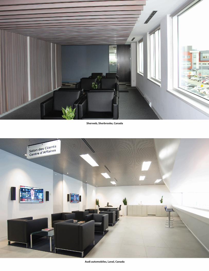
Audi automobiles, Laval, Canada
Sherweb, Sherbrooke, Canada
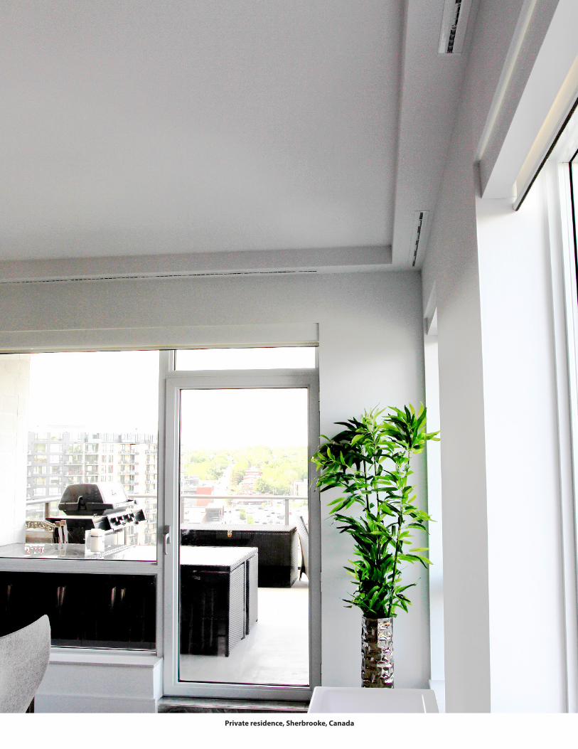
Private residence, Sherbrooke, Canada
L i s t o f s y m b o l s a n d b a s i c c o n c e p t®
NAD Klima144, rue Léger,
Sherbrooke, QC, J1L 1L9 CanadaT : 819 780-0111 • 1 866 531-1739
F : 819 [email protected]
NAD Klima Ontario 2840, Argentia Road, Unit 6,
Mississauga, ON, L5N 8G4 CanadaT : 416-860-1067
D A L 3 5 8®
®
www.nadklima.com
MADE IN