samia italia technical catalogue index … outline new.pdf · samia ® italia technical catalogue...
TRANSCRIPT
Tel. +39 0396065920Fax. +39 0396064548 e-mail:[email protected]
www.samiasrl.com
SAMIA® ITALIA SrlVia Bergamo, 3923807 Merate (LC) - ITALY
SAMIA® ITALIA TECHNICAL CATALOGUE
INDEX
Section 1
REFINERY BURNERS
- SRX (Fuel Staged loNOx, Gas firing Burner)
• Principle of operation
• Natural Draft Burner
• Forced Draft Burner
• Flame Chart (Width, Length)
- SRG (Air Staged loNOx, Oil/Gas combination
firing Burner)
• Principle of operation
• Natural Draft Burner
• Forced Draft Burner
• Flame Chart (Width, Length)
Samia® Italia Srl is an independent Organization NOT being associated to any other entity showing same Brand Name and/or Logo

Section 2.B
FLARE TIPS
• Barrel Flare Tip
• Steam Assisted Flare Tip
• Air Assisted Flare Tip
• Sonic/Multipoint Flare Tips
Section 2.C
FLARE SEALS
• Diode Pinecone Seal
• Molecular Seal
Section 2
FLARES
- GENERALITIES
• Achievable Emission Limits/Reductions
• Typical Industrial Applications
• Emission Stream Characteristics
• Emission Stream Pre-treatment Requirements
• Theory of Operation
• Steam-assisted flares
• Air-assisted flares
• Sonic Flares
• Ground Flares
• Advantages
• Other Considerations
Section 2.A
FLARE ASSEMBLIES
• Self Supported
• Guy Supported
• Derrick Supported

Section 1REFINERY BURNERS
SRX Burner Fuel Staged loNOx, Gas Firing
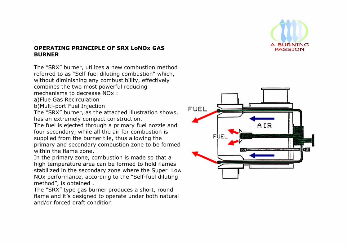
OPERATING PRINCIPLE OF SRX LoNOx GAS BURNER
The “SRX” burner, utilizes a new combustion method referred to as “Self-fuel diluting combustion” which, without diminishing any combustibility, effectively combines the two most powerful reducing
mechanisms to decrease NOx :a)Flue Gas Recirculationb)Multi-port Fuel InjectionThe “SRX” burner, as the attached illustration shows, has an extremely compact construction.
The fuel is ejected through a primary fuel nozzle and four secondary, while all the air for combustion is supplied from the burner tile, thus allowing the primary and secondary combustion zone to be formed
within the flame zone.In the primary zone, combustion is made so that a high temperature area can be formed to hold flames stabilized in the secondary zone where the Super Low NOx performance, according to the “Self-fuel diluting
method”, is obtained .The “SRX” type gas burner produces a short, round flame and it’s designed to operate under both natural and/or forced draft condition
# 007
# 010
# 015
# 020
# 025
# 030
# 040
0
50
100
150
200
250
300
350
400
450
500
2 4 6 8 10 12
DRAFT LOSS = mm H 2 O
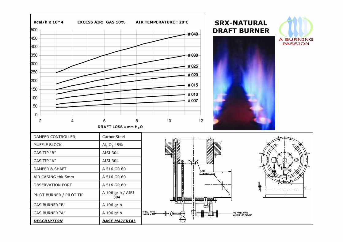
BASE MATERIALDESCRIPTION
A 106 gr bGAS BURNER “A”
A 106 gr bGAS BURNER “B”
A 106 gr b / AISI 304
PILOT BURNER / PILOT TIP
A 516 GR 60OBSERVATION PORT
A 516 GR 60AIR CASING thk 5mm
A 516 GR 60DAMPER & SHAFT
AISI 304GAS TIP “A”
AISI 304GAS TIP “B”
Al2O345%MUFFLE BLOCK
CarbonSteelDAMPER CONTROLLER
SRX-NATURAL DRAFT BURNER
Kcal/h x 10^4 EXCESS AIR: GAS 10% AIR TEMPERATURE : 20°C
# 007
# 010
# 015
# 020
# 025
# 030
# 040
0
100
200
300
400
500
600
700
800
900
1000
0 5 10 15 20 25 30 35 40 45
D R A F T LOSS = mm H 2 O
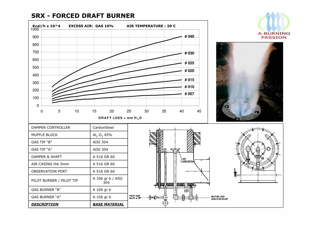
Kcal/h x 10^4 EXCESS AIR: GAS 10% AIR TEMPERATURE : 20°C
SRX - FORCED DRAFT BURNER
BASE MATERIALDESCRIPTION
A 106 gr bGAS BURNER “A”
A 106 gr bGAS BURNER “B”
A 106 gr b / AISI 304
PILOT BURNER / PILOT TIP
A 516 GR 60OBSERVATION PORT
A 516 GR 60AIR CASING thk 5mm
A 516 GR 60DAMPER & SHAFT
AISI 304GAS TIP “A”
AISI 304GAS TIP “B”
Al2O345%MUFFLE BLOCK
CarbonSteelDAMPER CONTROLLER
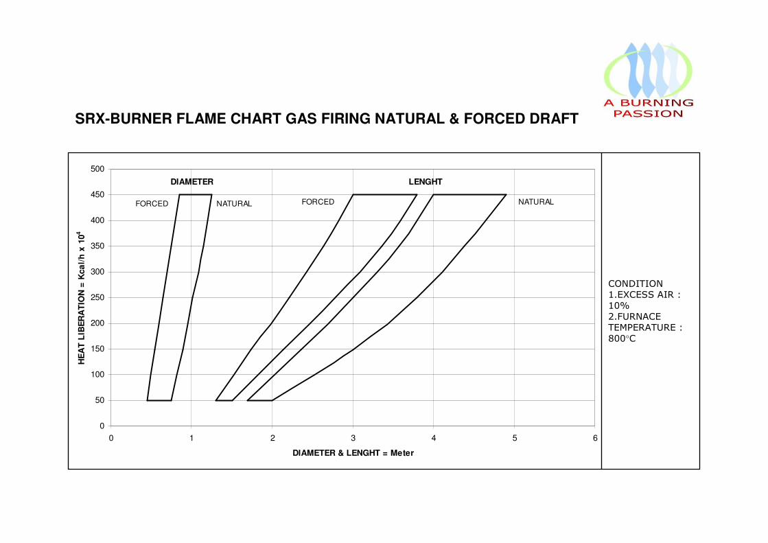
DIAMETER
FORCED
LENGHT
NATURALFORCED NATURAL
0
50
100
150
200
250
300
350
400
450
500
0 1 2 3 4 5 6
DIAMETER & LENGHT = Meter
HE
AT
LIB
ER
AT
ION
= K
ca
l/h
x 1
04
CONDITION1.EXCESS AIR : 10%2.FURNACE TEMPERATURE : 800°C
SRX-BURNER FLAME CHART GAS FIRING NATURAL & FORCED DRAFT

Section 1REFINERY BURNERS
SRG Burner Air Staged loNOx, Oil/Gas/Combination firing

OPERATING PRINCIPLE OF SRG LoNOx GAS AND/OR OIL BURNER
The “SRG” burner, without requiring any special power, recirculates air and part of the combustion products into the jet energy of fuel . Thus this is called on the “Self Recirculating Gasification” (SRG) burner . As the attached illustration shows , air and high temperature combustion products are introduced into the tile by the jet energy of fuel so that partial combustion and endo-thermic gas reaction takes place . NOx is drastically reduced by the effects of both flue gas recirculation and three stages combustion .

# 008
# 012
# 020
# 025
# 030
# 040
0
50
100
150
200
250
300
350
400
450
500
2 3 4 5 6 7 8 9 10 11 12
D R A F T LOSS = mm H 2 O
BASE MATERIALDESCRIPTION
AISI 304/A 106 gr bCOMBINATION BURNER
AISI 304/A 106 gr bPILOT BURNER
A 106 gr b / PIREXOBSERVATION PORT
A 516 GR 60AIR CASING thk 5mm
A 516 GR 60FRONT PLATE
A 516 GR 60DAMPER & SHAFT
CARBON STEELDAMPER CONTROLLER
Al2 O3 45%BURNER TILE
Al2 O3 45%BURNER BLOCK
Al2 O3 45%MUFFLE BLOCK
Kcal/h x 10^4 EXCESS AIR: GAS 10% - OIL 15% AIR TEMPERATURE : 20°C
SRGNATURAL DRAFT BURNER
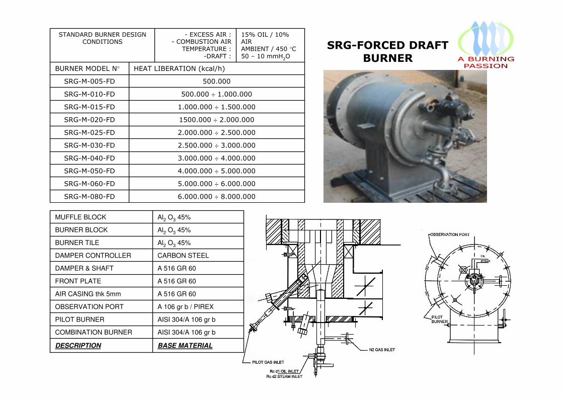
6.000.000 ÷ 8.000.000SRG-M-080-FD
5.000.000 ÷ 6.000.000SRG-M-060-FD
4.000.000 ÷ 5.000.000SRG-M-050-FD
3.000.000 ÷ 4.000.000SRG-M-040-FD
2.500.000 ÷ 3.000.000SRG-M-030-FD
2.000.000 ÷ 2.500.000SRG-M-025-FD
1500.000 ÷ 2.000.000SRG-M-020-FD
1.000.000 ÷ 1.500.000SRG-M-015-FD
500.000 ÷ 1.000.000SRG-M-010-FD
500.000SRG-M-005-FD
HEAT LIBERATION (kcal/h)BURNER MODEL N°
15% OIL / 10% AIRAMBIENT / 450 °C
50 – 10 mmH2O
- EXCESS AIR :- COMBUSTION AIR
TEMPERATURE :
-DRAFT :
STANDARD BURNER DESIGN CONDITIONS SRG-FORCED DRAFT
BURNER
BASE MATERIALDESCRIPTION
AISI 304/A 106 gr bCOMBINATION BURNER
AISI 304/A 106 gr bPILOT BURNER
A 106 gr b / PIREXOBSERVATION PORT
A 516 GR 60AIR CASING thk 5mm
A 516 GR 60FRONT PLATE
A 516 GR 60DAMPER & SHAFT
CARBON STEELDAMPER CONTROLLER
Al2 O3 45%BURNER TILE
Al2 O3 45%BURNER BLOCK
Al2 O3 45%MUFFLE BLOCK
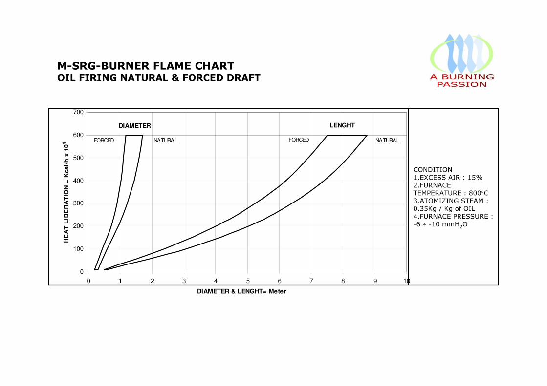
DIAMETER LENGHT
NATURALFORCEDNATURALFORCED
0
100
200
300
400
500
600
700
0 1 2 3 4 5 6 7 8 9 10
DIAMETER & LENGHT= Meter
HE
AT
LIB
ER
AT
ION
= K
cal/
h x
10
4
CONDITION1.EXCESS AIR : 15%2.FURNACE TEMPERATURE : 800°C3.ATOMIZING STEAM : 0.35Kg / Kg of OIL4.FURNACE PRESSURE :-6 ÷ -10 mmH2O
M-SRG-BURNER FLAME CHART OIL FIRING NATURAL & FORCED DRAFT
Section 2FLARES
GENERALITIES

Name of Technology: FlareThis includes elevated flares, steam-assisted flares, air-assisted flares, non-assisted flares, sonic flares, enclosed ground flares and Burn Pit Horizontal Flares.
Type of Technology: Destruction by thermal oxidation.
Achievable Emission Limits/ReductionsA properly operated flare can achieve a destruction efficiency of 98 percent or greater when controlling emission streams with heat contents greater than 11 MJ/sm3.
Typical Industrial ApplicationsFlares can be used to control almost any Gas Relief, and can typically handle large fluctuations in concentration, flow rate, heating value, and inert species content. Flaring is appropriate for continuous, batch, and variable flow vent stream applications, but the primary use is that of a safety device used to control a large volume of pollutant resulting from upset conditions. Flares find their primary application in the petroleum and petrochemical industries. The majority of chemical plants and refineries have existing flare systems designed to relieve emergency process upsets that require release of large volumes of gas.These large diameter flares are designed to handle emergency releases, but can also be used to controlvent streams from various process operations. Gases flared from refineries, petroleum production, andthe chemical industry are composed largely of low molecular weight Gas Relief and have high heating values.Flares used to control waste gases from blast furnaces consist of inert species and carbon monoxide witha low heating value. Gases flared from coke ovens are intermediate in composition to the other twogroups and have a moderate heating value.
Emission Stream Characteristicsa. Air Flow: The flow rate through the flare is dependent upon the properties of the waste gas stream and the configuration of the flare. Steam, air, and pressure-assisted flares add flow to the waste stream in order to improve flame stability. In cases where the heating value of the waste gas is too low or too high, auxiliary fuel or additional air must be added to the flow, respectively. The maximum flow through commercially available flares is about 500 standard cubic meters per second (sm3/sec) and the minimum can approach zero flow.
b. Temperature: The discharge temperature is typically in the range of 500 to 1100°C (1000 to2000°F), depending upon the composition of the waste gas flow.
c. Pollutant Loading: Depending upon the type of flare configuration (e.g., elevated or ground flares) and the source of the waste stream, the capacity of flares to treat waste gases can vary up to about 50,000 kilograms per hour (kg/hr) of hydrocarbon gases for ground flares and about 1 million kg/hr or more for elevated flares.
Flares are not subject to the safety concern of incinerators having a high concentration of organics in the waste gas. This is because flaring is an open combustion process and does not have an enclosed combustion chamber that can create an explosive environment. d. Other Considerations: The waste gas stream must have a heating value of greater than 11 MJ/Sm3 (300 Btu/Sf3). If this minimum is not met by the waste gas, auxiliary fuel must be introduced in sufficient quantity to make up the difference.
Emission Stream Pre-treatment RequirementsLiquids that may be in the vent stream gas or that may condense out in the collection header and transfer lines are removed by a knock-out drum. The knock-out is typically either a horizontal or vertical vessel located at or close to the base of the flare. Liquid in the vent stream can extinguish the flame or cause irregular combustion and smoking. In addition, flaring liquids can generate a spray of burning chemicals that could reach ground level and create a safety hazard.

Principle of OperationFlaring is a Gas Reliefs combustion control process in which the Gas Reliefs are piped to a remote, usually elevated, location and burned in an open flame in the open air, using a specially designed burner tip, auxiliary fuel and steam or air to promote mixing for nearly complete (> 98%) Gas Relief destruction. Completeness of combustion in a flare is governed by flame temperature, residence time in the combustion zone, turbulent mixing of the gas stream components to complete the oxidation reaction and available oxygen for free radical formation. Combustion is complete if all Gas Relief are converted to carbon dioxide and water.Incomplete combustion results in some of the Gas Reliefs being unaltered or converted to other organic compounds such as aldehydes or acids.Flares are generally categorized in two ways: (1) by the height of the flare tip (i.e., ground or elevated),and (2) by the method of enhancing mixing at the flare tip (i.e., steam-assisted, air-assisted or non-assisted). Elevating the flare can prevent potentially dangerous conditions at ground level where the open flame (i.e., an ignition source) is located near a process unit. Elevating the flare also allows the products of combustion to be dispersed above working areas to reduce the effects of noise, heat, Smoke, and objectionable odours.In most flares, combustion occurs by means of a diffusion flame. A diffusion flame is one in which air diffuses across the boundary of the fuel/combustion product stream toward the centre of the fuel flow, forming the envelope of a combustible gas mixture around a core of fuel gas. This mixture, on ignition, establishes a stable flame zone around the gas core above the burner tip. This inner gas core is heatedby diffusion of hot combustion products from the flame zone.Cracking can occur with the formation of small hot particles of carbon that give the flame its characteristic luminosity. If there is an oxygen deficiency and if the carbon particles are cooled to below their ignition temperature, smoking occurs. In large diffusion flames, combustion product vortices can form around burning portions of the gas and shut off the supply of oxygen. This localized instability causes flame flickering, which can be accompanied by soot formation. As in all combustion processes, an adequate air supply and good mixing are required to complete combustion and minimize smoke. The various flare designs differ primarily in their accomplishment of mixing.

Air-assisted flaresSome flares use forced air to provide the combustion air and the mixing required for smokeless operation. Combustion air is provided by a fan in the bottom of the cylinder. The amount of combustion air can be varied by varying the fan speed.The principal advantage of air-assisted flares is that they can be used where steam is not available.Although air assistance is not usually used on large flares (because it is generally not economical when the gas volume is large) the number of large air-assisted flares being built is increasing.The non-assisted flare consists of a flare tip without any auxiliary provision for enhancing the mixing of air into its flame. Its use is limited to gas streams that have a low heat content and a low carbon/hydrogen ratio that burn readily without producing smoke. These streams require less air for complete combustion, have lower combustion temperatures that minimize cracking reactions, and are more resistant to cracking.
Sonic FlaresSonic flares use the vent stream pressure to promote mixing at the burner tip. Severalvendors now market proprietary, high pressure drop burner tip designs. If sufficient vent stream pressure is available, these flares can be applied to streams previously requiring steam or air assist for smokeless operation. They have multiple burner heads that are staged to operate based on the quantity of gas being released. The size, design, number, and group arrangement of the burner heads depend on the vent gas characteristics.
Steam-assisted flaresSteam-assisted flares are single burner tips, elevated above ground level for safety reasons, that burn the vented gas in a diffusion flame. They reportedly account for the majority of the flares installed and are the predominant flare type found in refineries and chemical plants. To ensure an adequate air supply and good mixing, this type of flare system injects steam into the combustion zone to promote turbulence for mixing and to induce air into the flame.
Ground FlaresAn enclosed flare's burner heads are inside a shell that is internally insulated. The shell reduces noise, luminosity, and heat radiation and provides wind protection. Enclosed, or ground-based flares are generally used instead of elevated flares for aesthetic or safety reasons. A high nozzle pressure drop is usually adequate to provide the mixing necessary for smokeless operation and air or steam assistance is not required. In this context, enclosed flares can be considered a special class of sonic or non-assisted flares. The height must be adequate for creating enough draft to supply sufficient air for smokeless combustion and for dispersion of the thermal plume. These flares are always at ground level.Enclosed flares generally have less capacity than open flares and are used to combust continuous, constant flow vent streams, although reliable and efficient operation can be attained over a wide range of design capacity. Stable combustion can be obtained with lower heat content vent gases than is possible with open flare designs (1.9 to 2.2 MJ/Sm3), probably due to their isolation from wind effects.
Burn Pit Horizontal FlaresSometimes erroneously called Ground Flares, this horizontal Flare Tips, are commonly used preferably in low manned areas were large amounts of liquids might be carried over through the Flare Tip itself into a pit adequately sized where these will deposit and, once reached combustible temperature, thank to flame heat of horizontal Flares, will be destroyed by combustion.
AdvantagesAdvantages of flares over other types of Gas Reliefs oxidizers.1. Can be an economical way to dispose of sudden releases of large amounts of gas;2. In many cases do not require auxiliary fuel to support combustion3. Can be used to control intermittent or fluctuating waste streams.
Other ConsiderationsFlaring is considered as a control option when the heating value of the emission stream cannot berecovered because of uncertain or intermittent flow as in process upsets or emergencies.

Section 2.AFLARE ASSEMBLIES
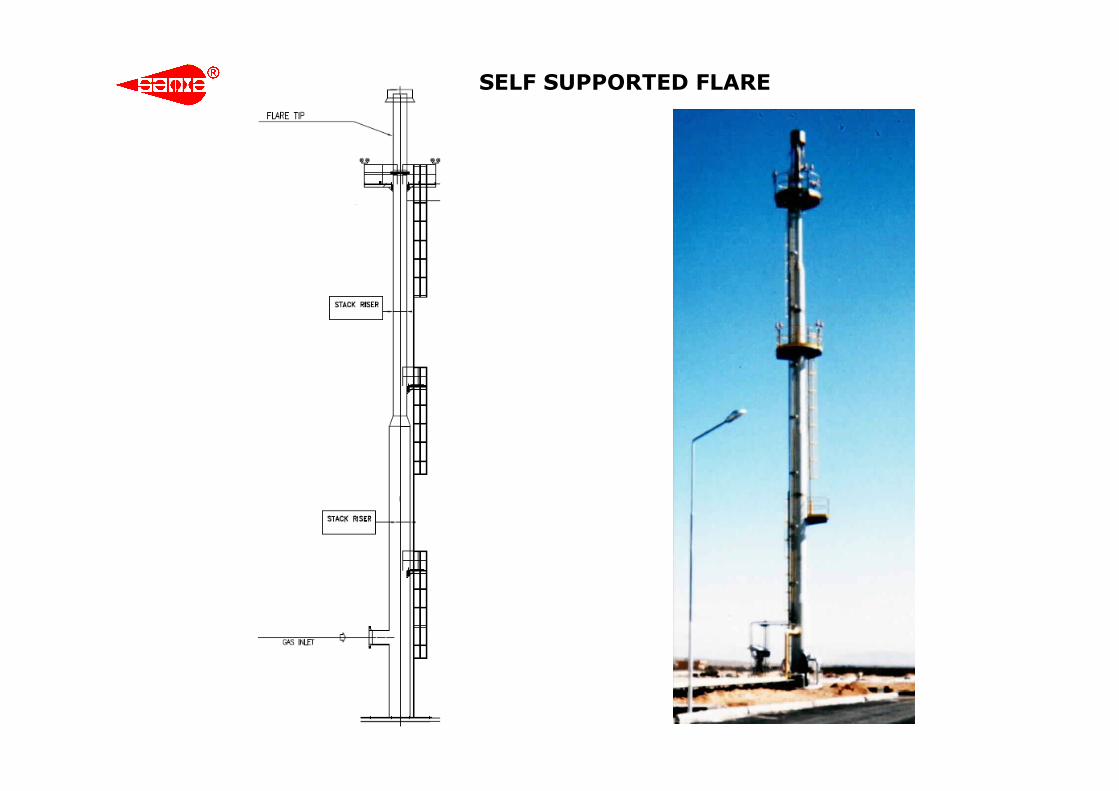
SELF SUPPORTED FLARE

GUY SUPPORTED FLARE
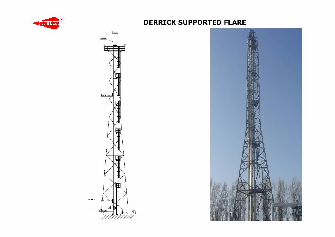
DERRICK SUPPORTED FLARE
Section 2.BFLARE TIPS

BARREL FLARE TIP

STEAM ASSISTED FLARE TIP

AIR ASSISTED FLARE TIP

SONIC / MULTIPOINT FLARE TIP
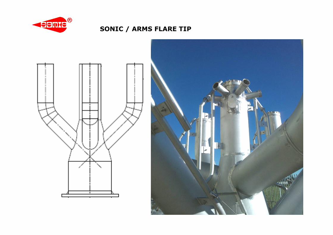
SONIC / ARMS FLARE TIP

Section 2.CFLARE SEALS
0,1
1
10
100
4 6 8 10 12 14 16 18 20 22 24 26 28 30 32 34 36 38 40 42 44 46 48 50 52 54 56 58 60
Tip Diameter [inches]
Flo
w R
ate
[N
m3/h
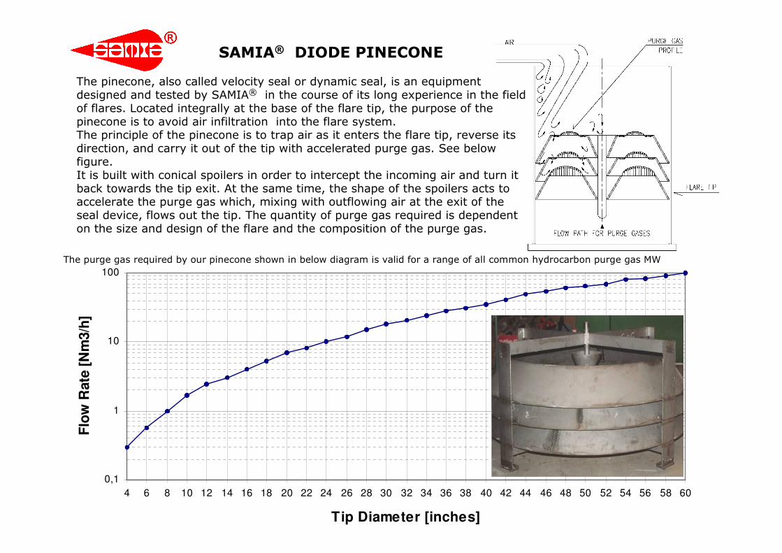
]The pinecone, also called velocity seal or dynamic seal, is an equipment designed and tested by SAMIA® in the course of its long experience in the field of flares. Located integrally at the base of the flare tip, the purpose of the pinecone is to avoid air infiltration into the flare system. The principle of the pinecone is to trap air as it enters the flare tip, reverse its direction, and carry it out of the tip with accelerated purge gas. See below figure. It is built with conical spoilers in order to intercept the incoming air and turn it back towards the tip exit. At the same time, the shape of the spoilers acts to accelerate the purge gas which, mixing with outflowing air at the exit of the seal device, flows out the tip. The quantity of purge gas required is dependent on the size and design of the flare and the composition of the purge gas.
The purge gas required by our pinecone shown in below diagram is valid for a range of all common hydrocarbon purge gas MW
SAMIA® DIODE PINECONE
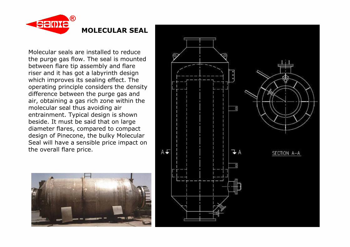
Molecular seals are installed to reduce the purge gas flow. The seal is mounted between flare tip assembly and flare riser and it has got a labyrinth design which improves its sealing effect. The operating principle considers the density difference between the purge gas and air, obtaining a gas rich zone within the molecular seal thus avoiding air entrainment. Typical design is shown beside. It must be said that on large diameter flares, compared to compact design of Pinecone, the bulky Molecular Seal will have a sensible price impact on the overall flare price.
MOLECULAR SEAL