sample - the ultimate cnc machinist source - cnc - cnc …cncbasics.com/interiorsample.pdf ·...
TRANSCRIPT
Sam
ple
1
CNC Programming product family.....
“CNC Programming: Basics & Tutorial Textbook”
“CNC Programming: Reference Book”
“CNC Programming: Workbook”
“CNC Programming: Workbook - Instructor Edition”
“CNC Programming: Basics & Tutorial”
“CNC Programming: Basics & Tutorial Textbook”
This book is an introduction to G-Code CNC programming. This book starts out explaining the basics in CNC programming along with practical information and explanation of code. Included in this book are four part tutorials with G-Code explanations for milling and lathes.
“CNC Programming: Reference Book”
This book has sections taken from “CNC Programming: Basics & Tutorial Textbook” as a refresher to programming. This book has reference information that the CNC Programmer will need on day to day work in the CNC programming area. This book has simple charts and formulas that will be the most valuable reference book in your toolbox.
“CNC Programming: Workbook”
This book has study questions, G-Code applications, and projects that aide in the understanding of CNC Programming. This workbook ties in parts from the “CNC Programming: Basics & Tutorial Text-book” & “CNC Programming: Reference Book”.
“CNC Programming: Basics & Tutorial”
This book is the original work by the author which has basic CNC Programming concepts of only mill-ing applications. The book is has been replaced by the “CNC Programming: Reference Book” and will no longer be updated. This book has basic information about milling programming.
Thank you for your interest in my products.
Sincerely,
Michael J Peterson
Sam
ple
7
CNC Programming
Beginning Basics of G-Code
Textbook
Sam
ple
9
Table of Contents
Introduction to CNC 112 Axis Fundamentals 23Cartesian Coordinate Systems 33
Introduction to G-Code 39Standard M-Codes 65
The Control Panel 77Programming Basics 89
The Toolpath 103 Milling Machining 113 Part1 Tutorial 117 Part2 Tutorial 141 Helical Interpolation Thread Milling 149
Lathe Machining 157 Part3 Tutorial 161 Part4 Tutorial 167
Sub-Programs 181Macros 199Appendix 207Index 213
Sam
ple
11
Introduction to CNC
Sam
ple
13
Introduction to CNCCNCFrom Wikipedia, the free encyclopedia
The abbreviation CNC stands for computer numerical control, and refers specifi cally to a computer “controller” that reads G-code instructions and drives a machine tool, a powered mechanical device typically used to fabricate components by the selective removal of material. CNC does numerically directed interpolation of a cutting tool in the work envelope of a machine. The operating parameters of the CNC can be altered via software load program.
CNC was preceded by NC (Numerically Controlled) machines, which were hard wired and their op-erating parameters could not be changed. NC was developed in the late 1940s and early 1950s by John T. Parsons in collaboration with the MIT Servomechanisms Laboratory. The fi rst CNC systems used NC style hardware, and the computer was used for the tool compensation calculations and sometimes for editing.
Punched tape continued to be used as a medium for transferring G-codes into the controller for many decades after 1950, until it was eventually superseded by RS232 cables, fl oppy disks, and now is commonly tied directly into plant networks. The fi les containing the G-codes to be interpreted by the controller are usually saved under the .NC extension. Most shops have their own saving format that matches their ISO certifi cation requirements.
The introduction of CNC machines radically changed the manufacturing industry. Curves are as easy to cut as straight lines, complex 3-D structures are relatively easy to produce, and the number of ma-chining steps that required human action has been dramatically reduced.
With the increased automation of manufacturing processes with CNC machining, considerable im-provements in consistency and quality have been achieved with no strain on the operator. CNC auto-mation reduced the frequency of errors and provided CNC operators with time to perform additional tasks. CNC automation also allows for more fl exibility in the way parts are held in the manufacturing process and the time required to change the machine to produce different components.
In a production environment, a series of CNC machines may be combined into one station, commonly called a “ cell”, to progressively machine a part requiring several operations. CNC machines today are controlled directly from fi les created by CAM software packages, so that a part or assembly can go directly from design to manufacturing without the need of producing a drafted paper drawing of the manufactured component. In a sense, the CNC machines represent a special segment of industrial robot systems, as they are programmable to perform many kinds of machining operations (within their designed physical limits, like other robotic systems). CNC machines can run over night and over weekends without operator intervention. Error detection features have been developed, giving CNC machines the ability to call the operator’s mobile phone if it detects that a tool has broken. While the machine is awaiting replacement on the tool, it would run other parts it is already loaded with up to that tool and wait for the operator. The ever changing intelligence of CNC controllers has dramatically increased job shop cell production. Some machines might even make 1000 parts on a weekend with no operator, checking each part with lasers and sensors.
Sam
ple
14
Introduction to CNC Types of instructionA line in a G-code fi le can instruct the machine tool to do one of several things.
MovementsThe most basic motion for a controller is to move the machine tool along a linear path from one point to another. Some machine tools can only do this in XY, and have to accept changes in Z separately. Some have two further axes of rotation to control the orientation of the cutter, and can move them simultaneously with the XYZ motion. Lately 4 and 5 axis machines have become popular. The 2 ad-ditional axis allow for the work surface or medium to be rotated around X and Y. For example, a 4-axis machine can move the tool head in XY and Z directions, and also rotate the medium around the X or Y axis, similar to a lathe. This is called the A or B axis in most cases.
All motions can be built from linear motions if they are short and there are enough of them. But most controllers can interpolate horizontal circular arcs in XY.
Lately, some controllers have implemented the ability to follow an arbitrary curve ( NURBS), but these efforts have been met with skepticism since, unlike circular arcs, their defi nitions are not natural and are too complicated to set up by hand, and CAM software can already generate any motion using many short linear segments.
With the advent of the vortech router cnc quad drive system which utilizes four (bidirectional) motors and drive, users are able to achieve greater speeds and accuracy.
DrillingA tool can be used to drill holes by pecking to let the swarf out. Using an internal thread cutting tool and the ability to control the exact rotational position of the tool with the depth of cut, it can be used to cut screw threads.
Drilling cyclesA drilling cycle is used to repeat drilling or tapping operations on a workpiece. The drilling cycle ac-cepts a list of parameters about the operation, such as depth and feed rate. To begin drilling any num-ber of holes to the specifi cations confi gured in the cycle, the only input required is a set of coordinates for hole location. The cycle takes care of depth, feed rate, retraction, and other parameters that ap-pear in more complex cycles. After the holes are completed, the machine is given another command to cancel the cycle, and resumes operation.
Parametric programmingA more recent advancement in CNC interpreters is support of logical commands, known as paramet-ric programming. Parametric programs incorporate both G-code and these logical constructs to cre-ate a programming language and syntax similar to BASIC. Various manufacturers refer to parametric programming in brand-specifi c ways. For instance, Haas refers to parametric programs as macros. GE Fanuc refers to it as Custom Macro A & B, while Okuma refers to it as User Task 2. The program-mer can make if/then/else statements, loops, subprogram calls, perform various arithmetic, and manipulate variables to create a large degree of freedom within one program. An entire product line of different sizes can be programmed using logic and simple math to create and scale an entire range of parts, or create a stock part that can be scaled to any size a customer demands.
Sam
ple
15
Introduction to CNC
Parametric programming also enables custom machining cycles, such as fi xture creation and bolt circles. If a user wishes to create additional fi xture locations on a work holding device, the machine can be manually guided to the new location and the fi xture subroutine called. The machine will then drill and form the patterns required to mount additional vises or clamps at that location. Parametric programs are also used to shorten long programs with incremental or stepped passes. A loop can be created with variables for step values and other parameters, and in doing so remove a large amount of repetition in the program body.
Because of these features, a parametric program is more effi cient than using CAD/CAM software for large part runs. The brevity of the program allows the CNC programmer to rapidly make performance adjustments to looped commands, and tailor the program to the machine it is running on. Tool wear, breakage, and other system parameters can be accessed and changed directly in the program, allow-ing extensions and modifi cations to the functionality of a machine beyond what a manufacturer envi-sioned.
There are three types of variables used in CNC systems: Local variable, Common variable, and System variable. Local variable is used to hold data after machine off preset value. Common variable is used to hold data if machine switch off does not erase form data. The System variable this vari-able used system parameter this cannot use direct to convert the common variable for example Tool radius, Tool length and tool height to be measured in mm or inches.
Sam
ple
18
Introduction to CNC
There are other codes; the type codes can be thought of like registers in a computer• X absolute position• Y absolute position• Z absolute position• A position (rotary around X)• B position (rotary around Y)• C position (rotary around Z)• U Relative axis parallel to X• V Relative axis parallel to Y• W Relative axis parallel to Z• M code (otherwise referred to as a “Miscellaneous” function”)
• F feed rate• S spindle speed• N line number• R Arc radius or optional word passed to a subprogram/canned cycle• P Dwell time or optional word passed to a subprogram/canned cycle• T Tool selection• I Arc data X axis• J Arc data Y axis.• K Arc data Z axis, or optional word passed to a subprogram/canned cycle• D Cutter diameter/radius offset• H Tool length offset
Sam
ple
25
2 Axis FundamentalsFundamentals of G-Code
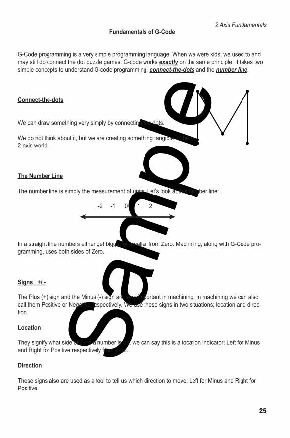
G-Code programming is a very simple programming language. When we were kids, we used to and may still do connect the dot puzzle games. G-code works exactly on the same principle. It takes two simple concepts to understand G-code programming, connect-the-dots and the number line.
Connect-the-dots
We can draw something very simply by connecting the dots.
We do not think about it, but we are creating something tangible in the 2-axis world.
The Number Line
The number line is simply the measurement of units. Let’s look at this number line:
-2 -1 0 1 2
In a straight line numbers either get bigger or smaller from Zero. Machining, along with G-Code pro-gramming, uses both sides of Zero.
Signs +/ -
The Plus (+) sign and the Minus (-) sign are very important in machining. In machining we can also call them Positive or Negative respectively. We use these signs in two situations; location and direc-tion.
Location
They signify what side of Zero a number is on, we can say this is a location indicator; Left for Minus and Right for Positive respectively from Zero.
Direction
These signs also are used as a tool to tell us which direction to move; Left for Minus and Right for Positive.
Sam
ple
43
Introduction to G-CodeStandard G-Codes - Mill
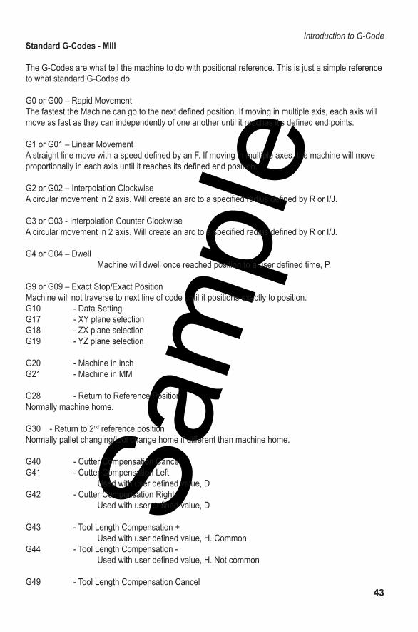
The G-Codes are what tell the machine to do with positional reference. This is just a simple reference to what standard G-Codes do.
G0 or G00 – Rapid Movement The fastest the Machine can go to the next defi ned position. If moving in multiple axis, each axis will move as fast as they can independently of one another until it reaches it’s defi ned end points.
G1 or G01 – Linear MovementA straight line move with a speed defi ned by an F. If moving in multiple axes, the machine will move proportionally in each axis until it reaches its defi ned end position.
G2 or G02 – Interpolation ClockwiseA circular movement in 2 axis. Will create an arc to a specifi ed radius defi ned by R or I/J.
G3 or G03 - Interpolation Counter ClockwiseA circular movement in 2 axis. Will create an arc to a specifi ed radius defi ned by R or I/J.
G4 or G04 – Dwell Machine will dwell once reached position to a user defi ned time, P.
G9 or G09 – Exact Stop/ Exact PositionMachine will not traverse to next line of code until it positions exactly to position. G10 - Data SettingG17 - XY plane selectionG18 - ZX plane selectionG19 - YZ plane selection
G20 - Machine in inchG21 - Machine in MM
G28 - Return to Reference Position Normally machine home.
G30 - Return to 2nd reference position Normally pallet changing/tool change home if different than machine home.
G40 - Cutter Compensation CancelG41 - Cutter Compensation Left Used with user defi ned value, DG42 - Cutter Compensation Right Used with user defi ned value, D
G43 - Tool Length Compensation + Used with user defi ned value, H. CommonG44 - Tool Length Compensation - Used with user defi ned value, H. Not common
G49 - Tool Length Compensation Cancel
Sam
ple
117
Part1 Tutorial
Part1 TutorialThis is a sample part tutorial to begin basic milling programming. Included is a sample print, Part1, and a G-Code program to make the part.
The following is a detailed explanation of a standard Fanuc programmed part.
This program is a Milling program, programmed to the side of the tool.
The Part Zero for programming purposes of this part are:
X0 = Left Edge of Part Y0 = Bottom Edge of Part Z0= Top of Part
* Refer to print on following page.
***All Feeds and Spindle speeds and reference information are from the book “CNC Programming - Reference Book”

Sam
ple
118
Part1 Tutorial
Material: Aluminum 6061
Sam
ple
119
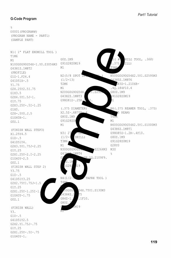
Part1 Tutorial G-Code Program
%O0001(PROGRAM#)(PROGRAM NAME - PART1)(SAMPLE PART)
N1( 1” FLAT ENDMILL TOOL )T1M6M1N100G0G90G54X-1.Y0.S3056M3G43H1Z.1M8T2(PROFILE)G1Z-1.F24.4G41D51X-.5Y1.75G2X.25Y2.5I.75G1X3.5G2X4.5Y1.5J-1.G1Y.75G2X3.25Y-.5I-1.25G1X0.G2X-.5Y0.J.5G1G40X-1.G0Z.1
(FINISH WALL STEP3)X1.25Y4.5G1Z-.5G41D51Y4.G2X3.5Y1.75J-2.25G1Y.25G2X1.25Y-2.I-2.25G1G40Y-2.5G0Z.1(FINISH WALL STEP 2)Y3.75G1Z-.5G41D51Y3.25G2X2.75Y1.75J-1.5G1Y.25G2X1.25Y-1.25I-1.5G1G40Y-1.75G0Z.1
(FINISH WALL)Y3.G1Z-.5G41D51Y2.5G2X2.Y1.75J-.75G1Y.25G2X1.25Y-.5I-.75G1G40Y-1.
G0Z.1M9G91G28Z0M19M1
N2(5/8 SPOT DRILL TOOL )(1/2-13)T2M6M1N200G0G90G54X.75Y1.S2500M3G43H2Z.1M8T3G98G81Z-.25R.1F10.
(.375 DIAMETER)X2.5Z-.6875R-.4G80Z.1M9G91G28Z0M19M1
N3( 27/64 DRILL TOOL)(1/2-13 DRILL)T3M6M1N300G0G90G54X.75Y1.S2264M3G43H3Z.1M8T4G98G83Z-1.2267R.1Q.2109F9.G80Z.1M9G91G28Z0M19M1
N4(1/2-13 CUT TAPRH TOOL )T4M6M1N400G0G90G54X.75Y1.S130M3G43H4Z.1M8T5G84Z-1.35R.1F10.G80Z.1M9G91G28Z0M19M1
N5( #U DRILL TOOL, .368)(.375 DRILL)T5M6M1N500G0G90G54X2.5Y1.S2595M3G43H5Z.1M8T6G98G83Z-1.2106R-.4Q.184F10.4G80Z.1M9G91G28Z0M19M1
N6(.375 REAMER TOOL, .375)(.375 REAM)T6M6M1N600G0G90G54X2.5Y1.S1000M3G43H6Z.1M8T1G98G85Z-1.2R-.4F10.G80Z.1M9G91G28Z0M19G28Y0M30%