sampled-data supervisory control - mcmaster universityleduc/studtheses/yuwangmascthesis09.pdf ·...
TRANSCRIPT

Sampled-data SupervisoryControl
By
Yu Wang, B.Eng
A ThesisSubmitted to the School of Graduate Studies
in partial fulfilment of the requirements for the degree of
Master of Applied ScienceDepartment of Computing and Software
McMaster University
c© Copyright by Yu Wang, January 15, 2009

ii
MASTER OF APPLIED SCIENCE(2006) McMaster University(Software Engineering) Hamilton, Ontario
TITLE: Sampled-data Supervisory Control
AUTHOR: Yu Wang, B.Eng(McMaster University)
SUPERVISOR: Dr. Ryan Leduc
NUMBER OF PAGES: i, 390
Abstract
This thesis focuses on issues related to implementing theoretical Discrete-Event Sys-tems (DES) supervisors, and the concurrency and timing delay issues involved.
Sampled-data (SD) supervisory control deals with timed DES (TDES) systemswhere the supervisors will be implemented as SD controllers. An SD controller isdriven by a periodic clock and sees the system as a series of inputs and outputs. Oneach clock edge (tick event), it samples its inputs, changes states, and updates itsoutputs.
In this thesis, we identify a set of existing TDES properties that will be usefulto our work, but not sufficient. We extend the TDES controllability definition toa new definition, SD controllability, which captures several new properties that willbe useful in dealing with concurrency issues, as well as make it easier to translate aTDES supervisor into an SD controller.
We then establish a formal representation of an SD controller as a Moore FiniteState Machine (FSM), and describe how to translate a TDES supervisor to a FSM, aswell as necessary properties to be able to do so. We discuss how to construct a singlecentralized controller, as well as a set of modular controllers and show that they willproduce equivalent output.
Next, we capture the enablement and forcing action of a translated controller inthe form of a TDES supervisory control map, and show that the closed-loop behaviorof this map and the plant is the same as that of the plant and the original TDESsupervisor. We also show that our method is robust with respect to nonblocking andcertain variations in the actual behavior of our physical system.
We also introduce a set of predicate-based algorithms to verify the SD controlla-bility property, as well as certain other conditions that we require. We have createda software tool for verifying these conditions and provide the source code in theappendix. We have implemented these algorithms using binary decision diagrams(BDD).
For illustrative purpose, we have produced a set of examples which fail the keyconditions discussed in this thesis, as well as a successful application example basedon a Flexible Manufacturing System. We also presented the corresponding FSM,
iii

iv
translated from the example’s supervisors.

Acknowledgment
I will definitely first give my thanks to my supervisor, Dr. Ryan Leduc, who I havebeen working for since I was an undergraduate. I would have never been able toaccomplish this task without the great great amount time, constant guidance, andsupport he has given me. His expertise in the area of discrete event control systemsis the most valuable source of help for the whole period of this work.
I’d also like to thank Raoguang Song for his preceding work on the BDD basedsymbolic verification tool for HISC. His code base saved me a lot of effort in under-standing and starting the software implementation.
At last my thanks go to my beloved father Xuhong Wang, and mother Baoxi-ang Yun for their unlimited support and Wen Xie for her great understanding andconfidence in me. This thesis is dedicated to them.
v

vi

Contents
Contents vii
List of Figures xi
1 Introduction 11.1 Objective . . . . . . . . . . . . . . . . . . . . . . . . . . . . . . . . . 41.2 Related Work . . . . . . . . . . . . . . . . . . . . . . . . . . . . . . . 7
2 Discrete-Event Systems Preliminaries 112.1 Algebraic Preliminaries . . . . . . . . . . . . . . . . . . . . . . . . . . 11
2.1.1 Strings . . . . . . . . . . . . . . . . . . . . . . . . . . . . . . . 112.1.2 Languages . . . . . . . . . . . . . . . . . . . . . . . . . . . . . 122.1.3 Nerode Equivalence Relation . . . . . . . . . . . . . . . . . . . 12
2.2 Discrete Event Systems . . . . . . . . . . . . . . . . . . . . . . . . . . 132.2.1 Generator . . . . . . . . . . . . . . . . . . . . . . . . . . . . . 132.2.2 Synchronization and Product DES . . . . . . . . . . . . . . . 172.2.3 Controllability and Supervision . . . . . . . . . . . . . . . . . 19
2.3 Timed Discrete Event Systems . . . . . . . . . . . . . . . . . . . . . . 212.3.1 Basic Structure . . . . . . . . . . . . . . . . . . . . . . . . . . 222.3.2 Controllability and Supervision . . . . . . . . . . . . . . . . . 22
3 Sampled-Data Systems 313.1 Sampling Inputs . . . . . . . . . . . . . . . . . . . . . . . . . . . . . . 333.2 SD Controllable Languages . . . . . . . . . . . . . . . . . . . . . . . . 373.3 Future Work . . . . . . . . . . . . . . . . . . . . . . . . . . . . . . . . 45
4 Moore Synchronous Finite State Machines 474.1 Formal Model . . . . . . . . . . . . . . . . . . . . . . . . . . . . . . . 484.2 Translation Method . . . . . . . . . . . . . . . . . . . . . . . . . . . . 52
4.2.1 Event Mapping Functions . . . . . . . . . . . . . . . . . . . . 534.2.2 Output Equivalence . . . . . . . . . . . . . . . . . . . . . . . . 54
vii

viii CONTENTS
4.2.3 Centralized Controller . . . . . . . . . . . . . . . . . . . . . . 574.2.4 Modular Controllers . . . . . . . . . . . . . . . . . . . . . . . 63
5 Control and Nonblocking Verification 735.1 Supervisory Control Construction . . . . . . . . . . . . . . . . . . . . 735.2 Map V Is Well Defined . . . . . . . . . . . . . . . . . . . . . . . . . . 805.3 Supervisory Control and SD Supervisors . . . . . . . . . . . . . . . . 835.4 Concurrent Supervisory Control Equivalent . . . . . . . . . . . . . . . 100
6 Symbolic Verification for SD System 1136.1 Predicates and Predicate Transformers . . . . . . . . . . . . . . . . . 113
6.1.1 State Predicates . . . . . . . . . . . . . . . . . . . . . . . . . . 1136.1.2 Predicate Transformers . . . . . . . . . . . . . . . . . . . . . . 115
6.2 Symbolic Representation . . . . . . . . . . . . . . . . . . . . . . . . . 1166.2.1 State Subsets . . . . . . . . . . . . . . . . . . . . . . . . . . . 1166.2.2 Transitions . . . . . . . . . . . . . . . . . . . . . . . . . . . . 117
6.3 Symbolic Computation . . . . . . . . . . . . . . . . . . . . . . . . . . 1196.3.1 Transitions and Inverse Transitions . . . . . . . . . . . . . . . 1196.3.2 Computation of Predicate Transformers . . . . . . . . . . . . 121
6.4 Symbolic Verification . . . . . . . . . . . . . . . . . . . . . . . . . . . 1236.4.1 Untimed Controllability . . . . . . . . . . . . . . . . . . . . . 1246.4.2 Plant Completeness . . . . . . . . . . . . . . . . . . . . . . . . 1266.4.3 Non-blocking . . . . . . . . . . . . . . . . . . . . . . . . . . . 1276.4.4 Activity Loop Free . . . . . . . . . . . . . . . . . . . . . . . . 1276.4.5 Proper Time Behavior . . . . . . . . . . . . . . . . . . . . . . 1286.4.6 SD Controllability and S-Singular Prohibitable Behavior . . . 129
7 Examples 1437.1 Examples . . . . . . . . . . . . . . . . . . . . . . . . . . . . . . . . . 144
7.1.1 Plant Completeness . . . . . . . . . . . . . . . . . . . . . . . . 1447.1.2 Activity Loop Free . . . . . . . . . . . . . . . . . . . . . . . . 1467.1.3 Proper Time Behavior . . . . . . . . . . . . . . . . . . . . . . 1477.1.4 SD Controllability . . . . . . . . . . . . . . . . . . . . . . . . 148
7.2 SD Controlled Flexible Manufacturing System . . . . . . . . . . . . . 1567.2.1 FMS Plants . . . . . . . . . . . . . . . . . . . . . . . . . . . . 1567.2.2 Buffer Supervisors . . . . . . . . . . . . . . . . . . . . . . . . 1577.2.3 B4 to Lathe Path . . . . . . . . . . . . . . . . . . . . . . . . . 1617.2.4 Moving Parts from B4 to B6/B7 . . . . . . . . . . . . . . . . . 1647.2.5 AM to Exit Path . . . . . . . . . . . . . . . . . . . . . . . . . 1647.2.6 System Shutdown . . . . . . . . . . . . . . . . . . . . . . . . . 169

CONTENTS ix
7.2.7 Algorithm Runtime Statistics . . . . . . . . . . . . . . . . . . 1717.3 Translating FSM Supervisors to Moore FSM . . . . . . . . . . . . . . 174
7.3.1 Adding More Timing Information . . . . . . . . . . . . . . . . 1747.3.2 FSM Controllers for Flexible Manufacturing System . . . . . . 176
8 Conclusions 183
Bibliography 187
A SD Software Program 191A.1 FMS Example Input Files . . . . . . . . . . . . . . . . . . . . . . . . 191
A.1.1 FMS Plants . . . . . . . . . . . . . . . . . . . . . . . . . . . . 191A.1.2 Helper Plants . . . . . . . . . . . . . . . . . . . . . . . . . . . 195A.1.3 Buffer Supervisors . . . . . . . . . . . . . . . . . . . . . . . . 197A.1.4 Additional Supervisors . . . . . . . . . . . . . . . . . . . . . . 201
A.2 Source code . . . . . . . . . . . . . . . . . . . . . . . . . . . . . . . . 208A.2.1 Main . . . . . . . . . . . . . . . . . . . . . . . . . . . . . . . . 209A.2.2 Global Functions, Typedefs, Variables, Preprocessors symbols 216A.2.3 DES Class . . . . . . . . . . . . . . . . . . . . . . . . . . . . . 235A.2.4 Sub Class . . . . . . . . . . . . . . . . . . . . . . . . . . . . . 256A.2.5 LowSub Class . . . . . . . . . . . . . . . . . . . . . . . . . . . 299

x CONTENTS

List of Figures
1.1 The Occurrences of Two Events . . . . . . . . . . . . . . . . . . . . . 2
2.1 An Example DES . . . . . . . . . . . . . . . . . . . . . . . . . . . . . 152.2 An Example Failing ALF Property . . . . . . . . . . . . . . . . . . . 242.3 An Example Failing the Proper Time Behavior Property . . . . . . . 27
3.1 Nonminimal Example . . . . . . . . . . . . . . . . . . . . . . . . . . . 373.2 An Example for Point ii . . . . . . . . . . . . . . . . . . . . . . . . . 423.3 An Example for Point iii.1 . . . . . . . . . . . . . . . . . . . . . . . 433.4 An Example Failing Point iv . . . . . . . . . . . . . . . . . . . . . . 433.5 SD Controllability and Arbitrary Union. . . . . . . . . . . . . . . . . 44
4.1 FSM Translation Example . . . . . . . . . . . . . . . . . . . . . . . . 514.2 Centralized Control Equivalence Diagram . . . . . . . . . . . . . . . . 60
5.1 An Example Failing S-singular Prohibitable Behavior Property . . . . 745.2 Part of a TDES plant . . . . . . . . . . . . . . . . . . . . . . . . . . . 805.3 An Example for Concurrent Supervisory Control Equivalence . . . . . 102
7.1 Legend Used to Display DES . . . . . . . . . . . . . . . . . . . . . . 1437.2 Plant Completeness Example: Plant . . . . . . . . . . . . . . . . . . 1457.3 Plant Completeness Example: Supervisor . . . . . . . . . . . . . . . . 1457.4 Activity Loop Example . . . . . . . . . . . . . . . . . . . . . . . . . . 1467.5 Proper Time Behavior Example . . . . . . . . . . . . . . . . . . . . . 1477.6 SD Controllability i, ii Example: Plant . . . . . . . . . . . . . . . . . 1497.7 SD Controllability Point i, ii Example: Supervisor . . . . . . . . . . . 1507.8 SD Controllability Point iii.1 Example: Plant . . . . . . . . . . . . . 1527.9 SD Controllability Point iii.1 Example: Supervisor . . . . . . . . . . . 1527.10 SD Controllability Point iii.2 Example: Plant . . . . . . . . . . . . . 1537.11 SD Controllability Point iii.2 Example: Supervisor . . . . . . . . . . . 1537.12 SD Controllability Point iv Example: Plant . . . . . . . . . . . . . . 155
xi

xii LIST OF FIGURES
7.13 SD Controllability Point iv Example: Supervisor . . . . . . . . . . . . 1557.14 Flexible Manufacturing System Overview . . . . . . . . . . . . . . . . 1567.15 Conveyor - Con2 . . . . . . . . . . . . . . . . . . . . . . . . . . . . . 1577.16 Robot . . . . . . . . . . . . . . . . . . . . . . . . . . . . . . . . . . . 1577.17 Lathe . . . . . . . . . . . . . . . . . . . . . . . . . . . . . . . . . . . 1587.18 Finishing Machine - AM . . . . . . . . . . . . . . . . . . . . . . . . . 1587.19 Conveyor - Con3 . . . . . . . . . . . . . . . . . . . . . . . . . . . . . 1587.20 Painting Machine - PM . . . . . . . . . . . . . . . . . . . . . . . . . 1587.21 Supervisor B2 . . . . . . . . . . . . . . . . . . . . . . . . . . . . . . . 1597.22 Supervisor B4 . . . . . . . . . . . . . . . . . . . . . . . . . . . . . . . 1607.23 Supervisor B6 . . . . . . . . . . . . . . . . . . . . . . . . . . . . . . . 1607.24 Supervisor B7 . . . . . . . . . . . . . . . . . . . . . . . . . . . . . . . 1607.25 Supervisor B8 . . . . . . . . . . . . . . . . . . . . . . . . . . . . . . . 1607.26 TakeB2 . . . . . . . . . . . . . . . . . . . . . . . . . . . . . . . . . . 1627.27 B4Path . . . . . . . . . . . . . . . . . . . . . . . . . . . . . . . . . . 1627.28 LathePick . . . . . . . . . . . . . . . . . . . . . . . . . . . . . . . . 1637.29 TakeB4PutB6 . . . . . . . . . . . . . . . . . . . . . . . . . . . . . . 1657.30 TakeB4PutB7 . . . . . . . . . . . . . . . . . . . . . . . . . . . . . . 1657.31 Plant AddNo963 . . . . . . . . . . . . . . . . . . . . . . . . . . . . 1667.32 Plant AddNo965 . . . . . . . . . . . . . . . . . . . . . . . . . . . . 1667.33 Force963 . . . . . . . . . . . . . . . . . . . . . . . . . . . . . . . . . 1677.34 Force961 . . . . . . . . . . . . . . . . . . . . . . . . . . . . . . . . . 1677.35 AMChooser . . . . . . . . . . . . . . . . . . . . . . . . . . . . . . . 1687.36 Force965 . . . . . . . . . . . . . . . . . . . . . . . . . . . . . . . . . 1687.37 Plant SystDownNup . . . . . . . . . . . . . . . . . . . . . . . . . . 1707.38 Supervisor handleSystDown . . . . . . . . . . . . . . . . . . . . . . 1707.39 Plant AddNo921 . . . . . . . . . . . . . . . . . . . . . . . . . . . . 1707.40 Histogram for Memory Usage (Kbytes vs. seconds) . . . . . . . . . . 1737.41 New B4 . . . . . . . . . . . . . . . . . . . . . . . . . . . . . . . . . . 1757.42 New B6 . . . . . . . . . . . . . . . . . . . . . . . . . . . . . . . . . . 1757.43 New B7 . . . . . . . . . . . . . . . . . . . . . . . . . . . . . . . . . . 1757.44 New B4Path . . . . . . . . . . . . . . . . . . . . . . . . . . . . . . . . 1757.45 FSM B2 . . . . . . . . . . . . . . . . . . . . . . . . . . . . . . . . . . 1787.46 FSM Force963 . . . . . . . . . . . . . . . . . . . . . . . . . . . . . . . 1787.47 FSM Force965 . . . . . . . . . . . . . . . . . . . . . . . . . . . . . . . 1787.48 FSM B4 . . . . . . . . . . . . . . . . . . . . . . . . . . . . . . . . . . 1787.49 FSM B6 . . . . . . . . . . . . . . . . . . . . . . . . . . . . . . . . . . 1797.50 FSM B7 . . . . . . . . . . . . . . . . . . . . . . . . . . . . . . . . . . 1797.51 FSM B8 . . . . . . . . . . . . . . . . . . . . . . . . . . . . . . . . . . 1807.52 FSM LathePick . . . . . . . . . . . . . . . . . . . . . . . . . . . . . . 180
LIST OF FIGURES xiii
7.53 FSM TakeB2 . . . . . . . . . . . . . . . . . . . . . . . . . . . . . . . 1807.54 FSM B4Path . . . . . . . . . . . . . . . . . . . . . . . . . . . . . . . 1807.55 FSM Force961 . . . . . . . . . . . . . . . . . . . . . . . . . . . . . . . 1817.56 FSM handleSystDown . . . . . . . . . . . . . . . . . . . . . . . . . . 1817.57 FSM TakeB4PutB6 . . . . . . . . . . . . . . . . . . . . . . . . . . . . 1817.58 FSM TakeB4PutB7 . . . . . . . . . . . . . . . . . . . . . . . . . . . . 1817.59 FSM AMChooser . . . . . . . . . . . . . . . . . . . . . . . . . . . . . 182

xiv LIST OF FIGURES
Chapter 1
Introduction
In the area of Discrete-Event Systems (DES) [23], [29], [30], a lot of effort has been
devoted to studying standard properties such as nonblocking (a form of deadlock de-
tection) and controllability (a check on whether we can actually realize our desired
control law) in a theoretical setting. However, limited effort has been made in inves-
tigating what an implementation of a DES supervisor would be like, how to do the
conversion automatically, whether we can guarantee that it will retain the control-
lability and nonblocking properties of the theoretical supervisor, and how to handle
timing delay and concurrency issues inherent in an implementation. This thesis will
be attacking these problems, although issues with respect to timing delay will only
be partially dealt with due to time limitations.
A logical implementation method for DES supervisors would be sampled-data (SD)
controllers. An SD controller is driven by a periodic clock and sees the system as a
series of inputs and outputs. On each clock edge, it samples its inputs, changes state,
and updates its outputs. An example of an SD controller might be a programmable
logic controller (PLC) [4] or a Moore synchronous finite state machine (FSM) [7]. In
this thesis, we will focus on FSM SD controllers as they are a complete specification
of an SD controller, yet still quite generic allowing an FSM to be implemented in
digital logic, or as a computer program. For simplicity, we will assume inputs and
outputs of an FSM can take the value of true or false.
When we are using an SD controller to manage a given system, we associate an
input with each event, and output with each controllable event. We consider an
1

2 1. Introduction
event to have occurred when its corresponding input has gone true during a given
clock period. We consider a controllable event to be enabled when its corresponding
output has been set true by the controller, disabled otherwise.
As mentioned above, an SD controller samples the value of its inputs on each clock
edge, and uses this value to decide what its next internal state will be. This means
the SD controller knows nothing about its inputs until the clock edge, and then all it
learns is whether a given input is true or false, signifying that the corresponding event
has occurred sometime in the clock period that just ended. This means that for the
given clock period, all information about event ordering (which event occurred first
etc) is lost, as well as how often a given event occurred if it has occurred more than
once. The only ordering information that remains is which sampling period (clock
period) a given event occurred in.
As an example, consider Figure 1.1. Here we have inputs Event 1 and 2, as well
as our sampling clock. The diagram on the left shows when the inputs changed their
value, in particular that Event 1 occurred first in the second sampling period. When
Figure 1.1: The Occurrences of Two Events
the SD controller samples its inputs, it simply gets a true or false value, based on
the value of the input at the clock edge.1 As we can see in the diagram on the right,
1In our example, we are sampling our inputs when the clock signal rises from low to high (therising edge of the clock).
1. Introduction 3
the controller simply knows that both Event 1 and 2 occurred in the last sampling
period, nothing more.
Another important aspect of an SD controller is that it only changes state on a
clock edge, and the value of its outputs are a function of its current state. That means
its outputs can only change at a clock edge, and then must stay constant for the rest
of the clock period.
For DES supervisors, we generally assume that a supervisor knows immediately
when an event occurs, that it can change enablement information right away, and
that events occur in an interleaving fashion so the supervisor can always determine
the order events occurred in. Based on the above discussion, it is clear that an SD
controller implementation violates these assumptions. First, the controller must wait
until the next sampling instance (clock edge) before it will know if a given event has
occurred. If the control law said something like “once event α occurs, controllable
event β must not occur.” However if β can occur in the same sampling period as α,
β may have already occurred before we even know that α has occurred. Of course,
even if we did know right away that alpha had occurred, we would not be able to
update the enablement information for β until the next clock edge anyway, which
could be too late. If we wanted to make sure β did not occur in this clock period,
we would have to disable it at the start of the sampling period. This means that we
cannot enforce a policy where an event is initially enabled (disabled) at the start of a
clock period, and we then disable (enable) the event somewhere in the middle. Our
supervisor must have a policy that is correct and constant for the entire sampling
period.
Another important issue is event ordering. If we could get either string ‘αβ’ or
‘βα’ in the same clock period, our SD controller would only know that at least one
α and at least one β had occurred. It would not know which of the two had actually
occurred. If our DES supervisor enabled event γ when string ‘αβ’ occurs, but disables
γ when string ‘βα’ occurs, we could not implement this using an SD controller as it
would not be able to determine which of the two strings had occurred. This means
that a supervisor must always do the same thing for two concurrent strings containing
the same individual events, both immediately after the strings have occurred and in
the future. Of course, this raises the question of how to determine if two strings are
concurrent.

4 1. Introduction
1.1 Objective
Clearly, untimed DES does not provide a rich enough modeling method to allow us
to work with an SD controller, and its inherent timing information. Therefore, we
will base our work on the timed DES (TDES) theory developed by Brandin et al. [5]
[6]. TDES extends untimed DES theory by adding a new tick event, corresponding to
the tick of a global clock. The event set of a TDES contains the tick event as well as
other non-tick events called activity events. The occurrence of a tick event provides
us with a concept of time passing, allowing us to model upper and lower time bounds
for the occurrence of activity events. It also allows us to introduce a new type of
events called forcible events, which we can guarantee to occur and preempt the next
clock tick. This means that now we cannot only prevent some events (referred to as
prohibitable events in TDES terminology) from occurring by disabling them, but we
can also choose to have certain events occur before the next clock tick.
To make the TDES theory work with SD controllers, we identify a tick event
occurring with the clock edge that the SD controller uses for sampling and state
change. That means that once a tick event occurs, any two strings that are now
possible in the system and only contain a single tick at the end of the string, are
considered concurrent. We will refer to such strings as concurrent strings. If one
of these strings contains at least one different event from the other string, we can
distinguish between them. Otherwise, we must treat them the same.
Now that we can force an event to occur in a specific clock period, we have a new
concern with respect to nonblocking. The plant model might say that we can do either
an ‘αβτ ’ concurrent string, or a ‘βατ ’ string, where τ = tick. Both might be safe
to do, but depending on our implementation, only one of the two might ever occur.
Some reasons this could occur are due to time delay, or our implementation might be
a sequential program that must choose one version or the other to perform. It might
be the case that for some implementations, when two or more concurrent strings are
possible and they contain the same events but in a different order or numbers, not all
variations might ever actually occur. The problem is that one of the variations that
does not occur might have been the only path in the TDES back to a marked state.
Basically, if an SD controller cannot tell the difference between concurrent strings,
they should have the same marked future. This also means that marked strings can

1. Introduction 5
only be the empty string (represents the initial state of the system which is always
observable), or strings ending in a tick as these are the points in the system’s behavior
that are observable to an SD controller. We refer to such strings as sampled strings.
The next problem we intend to address is the issue of when a forced event should
occur. As noted by Balemi in [2] for untimed systems, controllable events tend to
be events fully under the control of our controller implementation.2 They may be
a software function we call, an output we set to true, or a message we send. That
means that we can make these events occur whenever we want. It is not unusual
that a plant might be modeled such that these events are suppose to only occur
under certain situations. This might be for flexibility (some implementations have
these restrictions, for example) or to make the system easier to model or understand.
However, the reality for some controller implementations is that these events could
occur even when the plant said they cannot. This also applies to forcible events. When
we are forcing an event to occur in a given clock period, we have no information on
when it will actually occur. Depending on our implementation, it could occur right
away, or in the middle or end of the clock period. We need to make sure that when it
finally does occur, it does not contradict the plant model so that our implementation
will correspond to the theoretical model in this respect.
The last issue we intend to address is the issue of when a forcible event should
actually occur. We want our supervisor specified in such a way that it is straightfor-
ward to convert it into an SD controller. Normally for DES systems, we are interested
in maximally permissive behavior. We enable all controllable events except for when
they must be disabled to enforce our control law, and to ensure the system is non-
blocking. However, controller implementations are usually much more procedural.
We would disable all controllable events until we want them to occur, and then dis-
able the event again once it has occurred. In our setup, we will be assuming that
the set of prohibitable events and forcible events are the same3 and that we disable
the event until we wish to force it, and then disable it once it has occurred. This
2This is generally a matter of how a system is modeled. We can always model the sending ofour enable/disable signal as the controllable event, and the occurrence of the actual action as theuncontrollable event. Of course, the occurrence of the enablement event would toggle the eligibilityof the uncontrollable event.
3Again, this is a matter of modeling. We can always model our forcing signal as the controllableevent, and then model the event corresponding to the actual action as an uncontrollable event thatmust occur before the next clock tick, once the forcing event has occurred.

6 1. Introduction
requires our supervisor to specify exactly which clock period the event should occur
in and this makes it very straight forward to translate to a controller. Currently,
a supervisor could say something like controllable event α is now enabled, and will
stay enabled for the next three clock cycles, but must occur before the fourth. You
could potentially force it sooner, but that might cause blocking. Such an ambiguous
supervisor will be a lot harder to translate to an SD controller.
In this thesis, we will develop a new property for TDES systems that will address
the above issues, as well as make our TDES supervisor more consistent with SD
controllers, making them easy to translate. First, we will provide the preliminaries of
untimed and timed DES in Chapter 2, which is required to understand the following
chapters.
Then in Chapter 3 we will introduce the sampled-data setting based on timed
DES. The sampled-data setting will be formally defined, and we will develop a new
property called SD controllability to address the issues we identified above.
In Chapter 4, we will provide the definition of Moore FSM [17] and a method to
translate a CS deterministic supervisor (defined in Chapter 3) into a Moore FSM con-
troller. We will present both a centralized translation method and a modular method.
We will then show that they will both produce equivalent output information.
Then in Chapter 5 we capture the enablement and forcing action of a translated
controller in the form of a TDES supervisory control map, and show that the closed
loop behavior of this map and the plant is the same as that of the plant and the
original TDES supervisor. We also show that our method is robust with respect to
nonblocking and certain variations in the actual behavior of our physical system.
In Chapter 6 we will introduce logic predicates and predicate transformers, as well
as symbolic representation and computation based on [26]. Then we will introduce a
set of algorithms to verify SD controllability and other properties of interest to us.
Then in Chapter 7 we will present examples which fail the key conditions in
this thesis, to help understand the definitions. We will then present a successful
application example inspired by the untimed Flexible Manufacturing System from
[11], including the Moore FSM controllers translated from the supervisors developed
in the example.
We will close the thesis with our conclusions and a brief discussion of future work.
Also, in the appendix we will present the input files used for the FSM example
1. Introduction 7
given in Chapter 7, as well as the source code for our software tool that we have
developed that implements the algorithms presented in Chapter 6. The software tool
makes use of binary decision diagrams (BDD) [8].
1.2 Related Work
Supervisory control of DES with timing information, known as timed DES (TDES),
was firstly introduced in [5], [6], based on the timed transition model from [19], [20],
and [21]. The theory added timing information to supervisory control allowing one
to specify lower and upper time bounds for events. It also introduced a forcing
technology to ensure certain events occur when we desired. We will use this as the
basis of our SD supervisory control theory.
Balemi [2] pointed out that typically, controllable events are part of the supervisor
implementation, and often can occur whenever we want them to. For simplicity, the
plant may be modeled such that these events are assumed to only occur at certain
times. Balemi’s plant completeness condition helps ensures that the implementation
of the supervisor will be consistent with the plant model so that controllable events
do not occur when the plant model says that they cannot.
In the sampled-data setting, if the same event occurs once or multiple times in
the same sampling period, an SD controller will not be able to detect a difference.
In [3], the authors require that the system has the property that an event cannot be
generated more than once during a sampling period. The paper also discussed the loss
of ordering information when events occur in the same sampling period. To handle
these timing related issues, the author adds a dispatcher to the existing supervisor
to solve the problems that could occur when event ordering cannot be ignored. The
model is implemented based on Petri Nets [16, 33] and an algorithm to translate the
Petri Net implementation into computer language is provided.
Translating abstract model into a computer understandable form is an interest-
ing topic for researchers. In [12], Leduc discusses the modeling and implementation
of real-life DES problems as well. Theorems for model reduction were created and
applied to the DES designed for a programmable logic controller (PLC) based man-
ufacturing testbed. The author investigated implementing DES as Moore finite state
machines (FSM) and created an implementation by hand for the testbed. As men-

8 1. Introduction
tioned earlier, FSM can be converted to other forms of state based logic sequences,
such as a relay ladder logic program for the testbed. The idea of implementing SD
controllers as FSM is motivated by this thesis.
Similarly, [18] also discusses translating DES into PLC programs. The difference
is that they first convert automata into the Grafcet language, which describes the
specification of logic controllers. They then translate the Grafcet language into a PLC
program. Both [12] and [18] uses automated manufacturing testbeds as examples.
In [9], DES theory is used as a tool to assist programming in the system con-
trol area. The authors describe an approach to generate Java code for concurrency
control automatically. The approach formalizes each individual code portion without
concurrency control into specifications, builds the DES model, and then generates
the code with verifications.
A real world application of DES supervisory control is given in [10], where Petri
Nets are used to model railway networks and ensure controllability and liveness.
An important tool to allow supervisory control methods to be applied to larger
systems, is the use of binary decision diagrams (BDD)[8]. BDD methods have been
applied to standard DES [32], [27], state tree structures [14], Hierarchical Interface-
based Supervisory Control [26], and state based control of TDES [24].
When synthesizing controllers there is often a need to consider other components
in the system, which lower the flexibility and increase the cost of synthesis in changing
environments. With the I/O based hierarchical structure from [22], each controller
can be designed independently, and controllability and nonblocking is retained when
the controllers are combined.
However, even if the DES supervisor is nonblocking for the DES plant does not
mean that the controller implementation is nonblocking as well. To ensure a controller
is nonblocking, [15] studied several different systems for implementing controllers.
The author suggested conditions to be satisfied for the implemented controllers to be
nonblocking.
Another practical issue in implementing controllers based on DES is communica-
tion. In [25], the authors study the communication between modular and decentral-
ized supervisors on switch networks. A communication model is then introduced for
a large distributed controller network where communication delay and collisions are
a concern. In [31], the authors resolve communication issues by introducing an asyn-

1. Introduction 9
chronous implementation. The work formalizes the delay between the controller and
the plant, and defines bounded-delay implementability, in addition to the standard
controllability and nonblocking properties.
10 1. Introduction

Chapter 2
Discrete-Event Systems
Preliminaries
Supervisory control theory provides a framework for the control of discrete-event
systems (DES), systems that are discrete in space and time. For a detailed exposition
of DES, see [29]. Below, we present a summary of the terminology that we use in this
thesis.
2.1 Algebraic Preliminaries
2.1.1 Strings
An alphabet Σ is defined to be a finite set of distinct symbols. A string over Σ is a
finite sequence of symbols σ1σ2..σk, where σi ∈ Σ for i = 1, 2, .., k. Given a string
s = σ1σ2..σk, |s| = k is the length of the string. The string ε is called the empty string
with |ε| = 0. Let Σ∗ be the set of all finite symbol sequences and define Σ+ be
Σ+ := Σ∗ − ε
Definition 2.1.1. Let s1, s2 ∈ Σ∗, where s1 = σ1σ2..σm and s2 = τ1τ2..τn. The
catenation of s1 and s2 is define to be cat : Σ∗ × Σ∗ → Σ∗ such that
cat(s1, ε) = cat(ε, s1) = s1 = σ1σ2..σm
cat(s1, s2) = s1s2 = σ1σ2..σmτ1τ2..τn
11

12 2. Discrete-Event Systems Preliminaries
As |s1| = m and |s2| = n, the length of concatenated string is |s1s2| = |s1|+ |s2| =m + n.
Definition 2.1.2. Let s, t ∈ Σ∗. We say s is a prefix of t, denoted as s ≤ t, if
(∃u ∈ Σ∗)su = t
By definition, we can see that a string s ∈ Σ∗ is a prefix of itself, as s ≤ s. Also,
ε is a prefix of all strings, as (∀s ∈ Σ∗)ε ≤ s.
2.1.2 Languages
Definition 2.1.3. Let L ⊆ Σ∗. The prefix closure of L, denoted as L, is defined as
L = s ∈ Σ∗|(∃t ∈ L)s ≤ t
By definition, we can see that a language L is a subset of the prefix closure of
itself, i.e. L ⊆ L. We say a language L ⊆ Σ∗ is prefix closed if L = L. Let K ⊆ L.
We say K is L-closed if K = K ∩ L.
Definition 2.1.4. Let L ⊆ Σ∗. The eligibility operator, EligL : Σ∗ → Pwr(Σ), is
defined for s ∈ Σ∗ as,
EligL(s) := σ ∈ Σ | sσ ∈ L
2.1.3 Nerode Equivalence Relation
Definition 2.1.5. Let X be a nonempty set. Let E ⊆ X ×X be a binary relation
on X. The relation E is an equivalence relation on X if
1. (∀x ∈ X)xEx (reflexivity)
2. (∀x, x′ ∈ X)xEx′ =⇒ x′Ex (symmetry)
3. (∀x, x′, x′′ ∈ X)xEx′ & x′Ex′′ =⇒ xEx′′ (transitivity) 1
1We use ‘&’ to stand for logical AND here to avoid confusion with later definitions in this section.

2. Discrete-Event Systems Preliminaries 13
Here we are using standard infix notation, where we use xEx′ to represent the
ordered pair (x, x′) ∈ E. For xEx′, we may also write x ≡ x′(modE).
For x ∈ X, let [x]E ⊆ X represent the subset of elements that are equivalent mod
E to x. That is
[x]E := x′ ∈ X|x′Ex
If relation E is understood by the context, we will just write [x]. We will also refer
to [x] as the coset or the equivalence class of x with respect to E.
Let s, t ∈ Σ∗, and L ⊆ Σ∗. We say s and t are Nerode equivalent with respect to
language L, if and only if they can be extended by any string u ∈ Σ∗ such that the
two extended strings are either both in L or neither in L. In this case, we write s ≡ t
(mod L) or s ≡L t. The formal definition is given below.
Definition 2.1.6. Let L ⊆ Σ∗. Let s, t ∈ Σ∗.
s ≡L t or s ≡ t (mod L)
iff
(∀u ∈ Σ∗)su ∈ L ⇐⇒ tu ∈ L
Essentially, if strings s and t are equivalent mod L, then they can both be extended
in the same way by right concatenation.
Example 2.1. Let Σ = α, β, γ, L = ε, α, β, αγ∗, βγ∗, then α ≡L β.
2.2 Discrete Event Systems
2.2.1 Generator
We model DES formally as a generator G, which is a five tuple
G = (Q, Σ, δ, q0, Qm)
where
Q is the state set.

14 2. Discrete-Event Systems Preliminaries
Σ is the finite set of distinct symbols representing event labels. We par-
tition Σ into two parts
Σ = Σc ∪ Σu
where
Σc is the set of controllable events, which can be enabled or
disabled by an external agent. A controllable event can only
occur when it is enabled.
Σu is the set of uncontrollable events, which cannot be disabled
by any external agent. Once the DES has reached a state
where an uncontrollable event can occur, the event cannot
be prevented.
δ : Q× Σ → Q is the (partial) transition function where each transition is
a tuple (q, σ, q′), where δ(q, σ) = q′. We refer to q as the exit (source)
state, and q′ as the entrance (destination) state. We write δ(q, σ)! if
δ(q, σ) is defined.
We can extend the transition function to δ : Q× Σ∗ → Q as
δ(q, ε) = q for q ∈ Q.
δ(q, sσ) = δ(δ(q, s), σ) for s ∈ Σ∗, σ ∈ Σ, and q ∈ Q.
as long as q′ = δ(q, s)! and δ(q′, σ)!.
q0 ∈ Q is the initial state.
Qm ⊆ Q is the subset of marked states.
We can extend the transition function to δ : Q× Σ∗ → Q as
δ(q, ε) = q for q ∈ Q.
δ(q, sσ) = δ(δ(q, s), σ) for s ∈ Σ∗, σ ∈ Σ, and q ∈ Q.
as long as q′ = δ(q, s)! and δ(q′, σ)!.
Example 2.2. Let G = (Q, Σ, δ, q0, Qm) be the DES shown in Figure 2.1. By con-
vention, a controllable event is graphically represented by a slash across its transition

2. Discrete-Event Systems Preliminaries 15
arrow. Marked states are represented by a black dot. The state pointed at by an arrow
with no exit state, is the initial state. For the DES shown we have:
Q = I, W,D;Σ = Σc ∪ Σu, where Σc = α, µ and Σu = β, λ;δ = (I, α, W ), (W,β, I), (W,λ,D), (D,µ, I);q0 = I; Qm = I
Figure 2.1: An Example DES
Given DES G = (Q, Σ, δ, q0, Qm), we have the following definitions.
Definition 2.2.1. A state q ∈ Q is reachable if
(∃s ∈ Σ∗)δ(q0, s)! and q = δ(q0, s)
Definition 2.2.2. A state q ∈ Q is coreachable if
(∃s ∈ Σ∗)δ(q, s)! and δ(q, s) ∈ Qm
To simplify the following discussions, we will always assume a given DES is reach-
able unless explicitly stated otherwise.
Definition 2.2.3. The closed behavior of DES G is
L(G) = s ∈ Σ∗|δ(q0, s)!
16 2. Discrete-Event Systems Preliminaries
Definition 2.2.4. The marked behavior of DES G is
Lm(G) = s ∈ Σ∗|δ(q0, s)! & δ(q0, s) ∈ Qm
Clearly, Lm(G) ⊆ L(G).
Definition 2.2.5. The control action for some q ∈ Q for DES G is defined to be
a mapping ζ : Q → Pwr(Σc) that takes q and returns a set of controllable events
enabled at q.
Definition 2.2.6. DES G is said to be nonblocking if every reachable state is also
coreachable. This can be expressed as
L(G) = Lm(G)
Definition 2.2.7. Let G = (Q, Σ, δ, q0, Qm) and let λ be an equivalence relation on
Q such that for q, q′ ∈ Q, q ≡ q′ mod λ if and only if
1. (∀s ∈ Σ∗)δ(q, s)! ⇐⇒ δ(q′, s)!
2. (∀s ∈ Σ∗)[δ(q, s)! & δ(q, s) ∈ Qm] ⇐⇒ [δ(q′, s)! & δ(q′, s) ∈ Qm]
Basically, for states q and q′ such that q ≡ q′ mod λ, they have the same future with
respect to L(G) and Lm(G). Based on this, for string s ∈ L(G), a state q = δ(qo, s)
represents all strings in Σ∗ that are equivalent to s mod L(G) and mod Lm(G).
Definition 2.2.8. DES G is said to be minimal, if
(∀q, q′ ∈ Q)q ≡ q′ (mod λ) ⇐⇒ q = q′
It says that for all states q, q′ ∈ Q, if q is equivalent to q′ mod λ, then q and q′ are
the same state. DES G is minimal if it does not have two distinct states in Q that
are λ equivalent.

2. Discrete-Event Systems Preliminaries 17
2.2.2 Synchronization and Product DES
In real world, it is often easier to model a system as several smaller components. For
a DES plant, we use the synchronous product operator to combine the individual DES
components instead of modeling the whole system at once. We first need to define
the natural projection operator and its inverse.
Let G = (Q, Σ, δ, q0, Qm) be a DES. Take Σo ⊆ Σ to be the set of observable
events through some filtering channel of the events generated by G.
Definition 2.2.9. The natural projection P : Σ∗ → Σ∗o is defined as follows. For
s ∈ Σ∗, σ ∈ Σ,
P (ε) = ε
P (σ) =
ε if σ /∈ Σo
σ if σ ∈ Σo
P (sσ) = P (s)P (σ)
Example 2.3. For Σ = α, β, γ, Σo = α, β and s = αβαγβα,
P (s) = P (α)P (β)P (α)P (γ)P (β)P (α) = αβαβα
Let L ⊆ Σ∗. We define P (L) ⊆ Σ∗o as an extension of the natural projection as
P (L) := P (s)|s ∈ L
We also define its inverse image P−1 : Pwr(Σ∗o) → Pwr(Σ∗) such that, for H ⊆ Σ∗
o
P−1(H) := s ∈ Σ∗|P (s) ∈ H
Example 2.4. For Σ = α, β, γ, µ, Σo = α, β and so = αβαβα, the inverse
projection is
P−1(so) := γ, µ∗αγ, µ∗βγ, µ∗αγ, µ∗βγ, µ∗αγ, µ∗

18 2. Discrete-Event Systems Preliminaries
Definition 2.2.10. For i = 1, 2, let Li ⊆ Σ∗i , Σ = Σ1 ∪ Σ2 and Pi : Σ∗ → Σ∗
i be
natural projections. The synchronous product of L1 and L2 is defined to be
L1||L2 = P−11 (L1) ∩ P−1
2 (L2)
= s ∈ Σ∗|P1(s) ∈ L1&P2(s) ∈ L2
Definition 2.2.11. Let G1 = (Q1, Σ, δ1, qo,1, Qm,1) and G2 = (Q2, Σ, δ2, qo,2, Qm,2)
be two DES defined over the same event set Σ. The product of two DES is defined as
G1 ×G2 = (Q1 ×Q2, Σ, δ1 × δ2, (qo,1, qo,2), Qm,1 ×Qm,2)
where δ1 × δ2 : Q1 ×Q2 × Σ → Q1 ×Q2 is defined as
(δ1 × δ2)((q1, q2), σ) := (δ1(q1, σ), δ2(q2, σ))
whenever δ1(q1, σ)! and δ2(q2, σ)!.
By Definition 2.2.11, we have L(G1×G2) = L(G1)∩L(G2) and Lm(G1×G2) =
Lm(G1) ∩ Lm(G2)
Definition 2.2.12. The meet of G1 and G2, or meet(G1,G2), is defined to be the
reachable subautomaton of the product DES G1 ×G2.
Definition 2.2.13. The synchronous product of DES Gi = (Qi, Σi, δi, qoi, Qmi
) (i =
1, 2), denoted G1||G2, is defined to be a reachable DES G with event set Σ = Σ1∪Σ2
and properties:
Lm(G) = Lm(G1)||Lm(G2), L(G) = L(G1)||L(G2)
Definition 2.2.14. Let G be a DES defined over Σ and Σ′ be another set of events
such that Σ ∩ Σ′ = ∅. The selfloop operation on G is defined as
selfloop(G, Σ′) = (Q, Σ ∪ Σ′, δ′, qo, Qm)
where δ′ : Q× (Σ ∪ Σ′) → Q is a partial function defined as
δ′(q, σ) :=
δ(q, σ) σ ∈ Σ, δ(q, σ)!
q σ ∈ Σ′
undefined otherwise

2. Discrete-Event Systems Preliminaries 19
For DES G′i (i = 1, 2) defined over event set Σi, we will always assume that the
synchronous product operator is implemented by first extending each DES to be over
Σ by adding selfloops, and then using the meet operator. More formally, we take
Σ = Σ1∪Σ2, and Gi = selfloop(G′i, Σ−Σi). We then have G′
1||G′2 = meet(G1,G2).
In the algorithms we develop in this thesis, we will always assume all DES are
combined with the product DES operator. If a portion of the system is actually
combined together using the synchronous product operator as is commonly done for
plant components, we will first add selfloops as above, and then use these new DES
from then on in our algorithms.
2.2.3 Controllability and Supervision
We will take language K to represent the desired safe behavior of our plant represented
by DES G = (Q, Σ, δ, q0, Qm). We want to make sure that the closed loop behavior
of the system – that is the behavior of plant G under control of K – is a subset of K.
As we mentioned earlier, our system’s event set Σ is partitioned into controllable
and uncontrollable events. If an undesirable controllable event is possible in G that
will cause the system to leave the behavior represented by K, we disable it and prevent
it from occurring. We cannot do this with an uncontrollable event, so we need to make
sure the plant never reaches a state where it can leave the desired behavior by an
uncontrollable event. We now express this formally below.
Definition 2.2.15. K is said to be controllable with respect to G if
(∀s ∈ K)(∀σ ∈ Σu)sσ ∈ L(G) =⇒ sσ ∈ K
We typically give this definition in the form of KΣu ∩ L(G) ⊆ K where KΣu
denotes the string sσ for s ∈ K and σ ∈ Σu. In other words, if the plant reaches a
state where uncontrollable event σ is possible, then σ must also be accepted by K.
By definition, ∅, L(G) and Σ∗ are all controllable with respect to G.
Another way to express this definition is
(∀s ∈ K ∩ L(G)) EligL(G)(s) ∩ Σu ⊆ EligK(s)
which is used in Point i of Definition 3.2.1 in Section 3.2.
20 2. Discrete-Event Systems Preliminaries
As we prefer to work with finite state automata than typically infinite languages,
we want to be able to express K as a DES supervisor.
Definition 2.2.16. Let G = (Q, Σ, δ, q0, Qm) be a DES. Let K ⊆ Σ∗. We say G
represents K if
K = Lm(G) and K = L(G)
Definition 2.2.17. Let S = (X, Σ, ξ, xo, Xm) be a DES. Let K ⊆ Σ∗, we say S
implements K, if
K = Lm(S) ∩ Lm(G) and K = L(S) ∩ L(G)
Recall that Σ = Σc ∪ Σu, where Σc is a set of controllable events which can be
enabled or disabled by external agents; and Σu is a set of uncontrollable events which
cannot be disabled. We refer to such an external agent as a supervisor, which will
formally define shortly.
Definition 2.2.18. Let L(S) be the language represented by DES S. We say S is a
supervisor for G, if
1. L(S) is controllable with respect to G, and
2. Lm(S) ∩ Lm(G) = L(S) ∩ L(G)
For convenience, we say S is controllable for G if L(S) is controllable with respect
to G.
We can think of a supervisor S = (X, Σ, ξ, xo, Xm) as a state machine that tracks
all the events generated by plant G. Together with current state x ∈ X as source
state, it takes each event as an input to its transition function ξ, then moves to the
destination state x′ ∈ X. Events in G are only allowed to occur when the event is
not disabled in S. We refer to the closed loop behavior of the system as the behavior
of our plant G under the control of supervisor S. This is typically represented as
the meet of G and S. If we modeled the system only using the synchronous product,
then this would be represented as G||S.
2. Discrete-Event Systems Preliminaries 21
As noted by Balemi in [2], controllable events tend to be events fully under the
control of our supervisor’s implementation. They may be a software function we call,
an output we set to true, or a message we send. That means that we can make these
events occur whenever we want. It is not unusual that a plant might be modeled
such that these events are suppose to only occur under certain situations. This
might be for flexibility (some implementations have these restrictions, for example)
or to make the system easier to model or understand. However, the reality for some
supervisor implementations is that these events could occur even when the plant said
they cannot. We refer to such situations as illegal transitions. The requirement is
formally defined in [2] as follows.
Definition 2.2.19. A plant G is complete for its supervisor S if
(∀s ∈ L(G) ∩ L(S))(∀σ ∈ Σc)sσ ∈ L(S) =⇒ sσ ∈ L(G)
The definition states that, at each state in plant G, every controllable event
enabled by supervisor S must be accepted by G as well. This condition can be seen
as a dual to the definition of a supervisor S being controllable for plant G. This
definition will be very useful for implementing DES supervisors, as it says that they
do not require additional supplementary information from the plant to decide when
a controllable event can occur and not violate the plant model.
2.3 Timed Discrete Event Systems
So far we have only discussed untimed DES. As we wish to use a richer modeling
framework that includes timing requirements of our system, we will now discuss Timed
DES (TDES) introduced by Brandin et al [5] [6].
TDES extends untimed DES theory by adding a new tick event, corresponding to
the tick of a global clock. The event set of a TDES contains the tick event as well
as other non-tick events called activity events (Σact). The occurrence of a tick event
provides us with a concept of time passing, allowing us to model upper and lower
time bounds for the occurrence of activity events. A lower time bound for a given
activity event can be modeled as requiring a certain number of tick events to first
occur before the activity event is eligible. Once an activity event is eligible to occur
22 2. Discrete-Event Systems Preliminaries
in the TDES and the desired number of tick events have occurred, we can model an
upper bound for the event by not allowing a tick event to occur until either the event
has occurred, or another activity event has occur such that the first event is no longer
eligible.
The addition of a tick event also allows us to introduce a new type of events called
forcible events (Σfor), which we guarantee to occur and preempt the next clock tick.
This means that now we cannot only prevent some events (referred to as prohibitable
events (Σhib) in TDES terminology) from occurring by disabling them, but we can
also choose to have certain events occur before the next clock tick. As a convention,
we sometimes refer to tick as τ for brevity.
2.3.1 Basic Structure
We formally define a TDES as the tuple
G = (Q, Σ, δ, q0, Qm)
where,
Q is the state set
Σ = Σact ∪ τ is the set of all events, including activity events and the
tick event.
δ : Q× Σ → Q is the (partial) transition function.
q0 ∈ Q is the initial state.
Qm ⊆ Q is the set of marked states.
For convenience, we extend δ to function δ : Q× Σ∗ → Q in the same way as we
did in the untimed DES definition.
2.3.2 Controllability and Supervision
Control action for timed DES is achieved in an analogous fashion as that of untimed
DES, by disabling controllable events. As for untimed DES, we also partition our
event set Σ into controllable and uncontrollable events. The set of controllable events
is defined to be

2. Discrete-Event Systems Preliminaries 23
Σc := Σhib ∪ τ
where Σhib ⊆ Σact the set of activity events that can disabled by an external agents.
These event are referred to as prohibitable events to distinguish them from control-
lable events that include the tick event. As we will see when we define controllability
in the TDES setting, we will use disabling the tick event by the supervisor to model
forcing an event. A forcible event is an event in the system that we can make occur
before the next clock tick, assuming it is not first preempted by another event. The
set of uncontrollable events for G is then defined to be
Σu := Σ− Σc
In Section 2.2.3, we introduced Balemi’s concept of completeness of a plant for
a given supervisor. Unfortunately, that definition was given in terms of controllable
events, which includes the tick event in TDES. As we are only concerned about the
occurrence of activity events, we need to define a version of this definition for TDES.
When discussing this concept, we will not specify whether or not we mean the timed
or untimed version, as this will be clear by the context.
Definition 2.3.1. Let TDES G be a plant and TDES S be a supervisor. G is TDES
complete for S if
(∀s ∈ L(G) ∩ L(S))(∀σ ∈ Σhib)sσ ∈ L(S) =⇒ sσ ∈ L(G)
We now need to add a technical condition that we most enforce to ensure that our
TDES does not allow the physically unrealistic situation where a tick event could be
preempted indefinitely by the continued execution of an activity event loop within a
given fixed unit time. Formally, a TDES is said to have an activity loop if it satisfies
the following definition.
Definition 2.3.2. TDES G = (Q, Σ, δ, q0, Qm) has an activity loop if
(∃q ∈ Q)(∃s ∈ Σ+act)δ(q, s) = q
We thus require that a TDES be activity loop free (ALF). We can formalize the
ALF concept as defined below.
24 2. Discrete-Event Systems Preliminaries
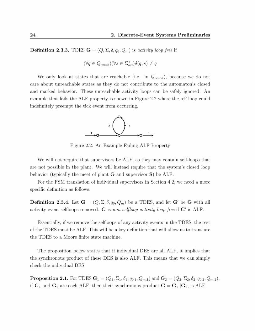
Definition 2.3.3. TDES G = (Q, Σ, δ, q0, Qm) is activity loop free if
(∀q ∈ Qreach)(∀s ∈ Σ+act)δ(q, s) 6= q
We only look at states that are reachable (i.e. in Qreach), because we do not
care about unreachable states as they do not contribute to the automaton’s closed
and marked behavior. These unreachable activity loops can be safely ignored. An
example that fails the ALF property is shown in Figure 2.2 where the αβ loop could
indefinitely preempt the tick event from occurring.
Figure 2.2: An Example Failing ALF Property
We will not require that supervisors be ALF, as they may contain self-loops that
are not possible in the plant. We will instead require that the system’s closed loop
behavior (typically the meet of plant G and supervisor S) be ALF.
For the FSM translation of individual supervisors in Section 4.2, we need a more
specific definition as follows.
Definition 2.3.4. Let G = (Q, Σ, δ, q0, Qm) be a TDES, and let G′ be G with all
activity event selfloops removed. G is non-selfloop activity loop free if G′ is ALF.
Essentially, if we remove the selfloops of any activity events in the TDES, the rest
of the TDES must be ALF. This will be a key definition that will allow us to translate
the TDES to a Moore finite state machine.
The proposition below states that if individual DES are all ALF, it implies that
the synchronous product of these DES is also ALF. This means that we can simply
check the individual DES.
Proposition 2.1. For TDES G1 = (Q1, Σ1, δ1, q0,1, Qm,1) and G2 = (Q2, Σ2, δ2, q0,2, Qm,2),
if G1 and G2 are each ALF, then their synchronous product G = G1||G2, is ALF.

2. Discrete-Event Systems Preliminaries 25
Proof. Let G1 = (Q1, Σ1, δ1, q0,1, Qm,1) and G2 = (Q2, Σ2, δ2, q0,2, Qm,2) be two TDES
and let P1 : Σ∗ → Σ∗1 and P2 : Σ∗ → Σ∗
2 be natural projections.
Define Σact,i = Σact ∩ Σi, i = 1, 2.
By ALF Definition 2.3.3, for i = 1, 2
(∀qi ∈ Qreach,i)(∀si ∈ Σ+act,i)δi(qi, si) 6= qi (∗)
where Qreach,i is the set of reachable states for Gi
Let G = G1||G2 = (Q, Σ, δ, q0, Qm)
Must show
(∀q ∈ Qreach)(∀s ∈ Σ+act)δ(q, s) 6= q
We will use proof by contradiction. Assume
(∃q ∈ Qreach)(∃s′ ∈ Σ+act)δ(q, s
′) = q
Let q = (q1, q2) ∈ Qreach be this state and let s′ ∈ Σ+act such that δ(q, s′) = q.
We know that q is a reachable state if and only if q1 ∈ Q1 and q2 ∈ Q2 are
reachable states in G1 and G2, respectively, by Definition of the || operator. We thus
have
δ(q, s′) = q =⇒ δ((q1, q2), s′) = (q1, q2)
=⇒ δ((q1, q2), s′) = (δ1(q1, P1(s
′)), δ2(q2, P2(s′))) by Definition of ||.
This implies
δ1(q1, P1(s′)) = q1
δ2(q2, P2(s′)) = q2
As s′ ∈ Σ+act we thus have s′ 6= ε. As Σ = Σ1 ∪Σ2, it follows that either P1(s
′) 6= ε or
P2(s′) 6= ε This implies that either G1 or G2 is not ALF, which contradicts(*).
Therefore it must be that
(∀q ∈ Qreach)(∀s ∈ Σ+act)δ(q, s) 6= q

26 2. Discrete-Event Systems Preliminaries
The above proposition can be applied to two TDES combined using the meet
operator as meet is a special case of the synchronous product.
We next present a proposition that says that to ensure the synchronous product
is ALF, it is sufficient that only one of the two TDES is ALF, as long as the event
set of the ALF TDES contains all of the events in the event set of the second TDES.
It means that if plant is over Σ and the supervisor introduces no new events, then we
can just check if the plant is ALF. As indicated by Proposition 2.1, we can check that
the plant is ALF by checking if each individual plant component is ALF. Therefore
an ALF algorithm does not have to check that the closed loop system is ALF, but
can check that the event set of the plant is a superset of the supervisor’s event set,
then do an ALF check on each individual TDES that makes up the plant. If the check
passes, then we are done. Otherwise, we do an ALF check on the entire system.
Proposition 2.2. Let G1 = (Q1, Σ1, δ1, qo,1, Qm,1) and G2 = (Q2, Σ2, δ2, qo,2, Qm,2)
be two TDES. If G1 is ALF and Σ1 ⊇ Σ2, then G1||G2 is also ALF.
Proof. Assume G1 is ALF and Σ1 ⊇ Σ2. (1)
Let G = G1||G2 = (Q, Σ, δ, qo, Qm) with Σ = Σ1 ∪ Σ2 and Pi : Σ∗ → Σ∗i for
i = 1, 2. Must show G is ALF.
We will do so by proof of contradiction.
Assume G is not ALF, then
(∃q ∈ Qreach)(∃s′ ∈ Σ+act)δ(q, s′) = q
Let q = (q1, q2) ∈ Qreach, and s′ ∈ Σ+act such that δ(q, s′) = q. (2)
We first note that q is reachable in G, which implies q1 is reachable in G1 and q2
is reachable in G2.
We next note that as Σ1 ⊇ Σ2, we have Σ = Σ1 ∪ Σ2 = Σ1. This implies that
P−11 L(G1) = L(G1). (3)
From (2), we have
δ(q, s′) = q =⇒ δ((q1, q2), s′) = (q1, q2)
=⇒ δ1(q1, P1(s′)) = q1
=⇒ δ1(q1, s′) = q1 by (3)
This contradicts (1) as it implies G1 is not ALF.
We thus conclude that G must be ALF.

2. Discrete-Event Systems Preliminaries 27
We are also want to make sure that the plant is not modeled in such a way that
our closed loop system could reach a state where no more tick events are possible, as
this “stopping the clock” would be physically unrealistic. To help prevent this, we
will require that our plant TDES have proper time behavior, as defined by Kai Wong
et al. [28].
Definition 2.3.5. TDES G has a proper time behavior if
(∀s ∈ L(G))EligL(G)(s) ∩ Σu = ∅ =⇒ τ ∈ EligL(G)(s)
This definition can be rewritten as
(∀q ∈ Qreach)(∃σ ∈ Σu ∪ τ)δ(q, σ)!
In other words, this TDES must guarantee that at all of its reachable states, either
a tick event or an uncontrollable event must be possible. This serves two purposes.
Combined with TDES G being ALF and having a finite state space, this ensures that
we call always reach a state where a tick is possible after at most a finite number
of activity events. We prove this shortly in Proposition 2.3. This condition will
also ensure we do not stop the clock when we combine our plant with a controllable
supervisor. An example that fails the proper time behavior property is shown in
Figure 2.3 where after the first tick event, neither an uncontrollable event or a tick
are possible, only the prohibitable event β.
Figure 2.3: An Example Failing the Proper Time Behavior Property
Consider the case where we have a reachable state where tick was ineligible, but
only controllable events were possible. If the supervisor disabled these controllable
events, there would now be no events possible at all. Proper time behavior ensures
that if tick was not possible at this state in the plant, there would be an uncontrollable
event possible, even if all the controllable events were disabled. The restriction of
proper time behavior applies only to plant TDES. It does not apply to supervisor
TDES or the meet of the plant and supervisor (i.e. the closed loop behavior of the
system).

28 2. Discrete-Event Systems Preliminaries
If a TDES G has a finite state space, is activity loop free and has proper time
behavior, then we expect that at any reachable state, we can always do a tick event
after at most a finite number of activity events. In other words, we will never “stop
the clock.” The following proposition shows that this is indeed the case.
Proposition 2.3. If a TDES G = (Q, Σ, δ, q0, Qm) has a finite statespace, is activity
loop free and has proper time behavior, then
(∀q ∈ Qreach)(∃s ∈ Σ∗)δ(q, sτ)!
where Qreach is the set of reachable states.
Proof. Assume that G has a finite statespace, is activity loop free, and has proper
time behavior
Let q ∈ Qreach.
Must show implies (∃s ∈ Σ∗)δ(q, sτ)!
We first note that as G has a finite statespace and is non-empty, there exists
n ∈ 1, 2, . . . such that n = |Q|.As G is ALF and has n states, it follows that
(∃s ∈ Σ+act)|s| ≤ n− 1 and
(∃q′ ∈ Qreach)δ(q, s) = q′ and
(∀σ ∈ Σact)δ(q′, σ) 6 ! (1)
The above follows from the fact that starting at q, we can do at most n− 1 activity
event transitions before we have visited all n states. At this point, there must be no
activity event transition or we would have to visit a state twice, creating an activity
loop and failing the ALF definition.
As Σu ⊆ Σact, (1) asserts that there are no uncontrollable events at state q′. It
thus follows that δ(q′, τ)!) as G has proper time behavior.
We thus have:
δ(q, sτ)!
as required.
2. Discrete-Event Systems Preliminaries 29
We now present the controllability definition for timed DES. Normally, we drop
the “TDES” and just say “controllable” as the meaning is clear from the context.
Definition 2.3.6. We define the arbitrary language K ⊆ L(G) to be TDES control-
lable with respect to G if,
(∀s ∈ K)EligK(s) ⊇
EligL(G)(s) ∩ (Σu ∪ τ) if EligK(s) ∩ Σfor = ∅EligL(G)(s) ∩ Σu if EligK(s) ∩ Σfor 6= ∅
Definition 2.3.6 says that a K must accept an uncontrollable event if the event
is possible in the plant, and it must accept a tick event if it is possible in the plant,
unless there exists an eligible forcible event that can preempt the tick.
Note that the closed and marked behavior of a TDES is defined in the same way as
for an untimed DES. A TDES is said to be nonblocking if Definition 2.2.6 is satisfied.
Proposition 2.4. If TDES plant G and TDES supervisor S both have finite states-
paces, G has proper time behavior, Gcl = meet(G,S) = (Q, Σ, δ, q0, Qm) is ALF,
and S is controllable for G, then
(∀q ∈ Qreach)(∃s ∈ Σ∗)δ(q, sτ)!
Proof. Assume:
• G and S have finite statespaces
• G has proper time behavior
• Gcl is ALF
• S is controllable for G
Let q ∈ Qreach. Must show (∃s ∈ Σ∗)δ(q, sτ)!
As G and S have finite statespaces, it follows from Definition 2.2.12 of the meet
operator, that Gcl has a finite statespace. Let n = |Q|.

30 2. Discrete-Event Systems Preliminaries
As Gcl is ALF and has n states, it follows that
(∃s ∈ Σ+act)|s| ≤ n− 1 and
(∃q′ ∈ Qreach)δ(q, s) = q′ and
(∀σ ∈ Σact)δ(q′, σ) 6 ! (1)
The above follows from the fact that starting at q, we can do at most n− 1 activity
event transitions before we have visited all n states. At this point, there must be no
more activity event transitions or we would have to visit a state twice, creating an
activity loop and failing the ALF definition.
We now need to show tick is defined at q′. From (1), we know that there are no
untimed events possible in Gcl at q′ as Σu ⊆ Σact. As S is controllable for G, this
implies there are no untimed events possible at the corresponding state in G. As G
has proper time behavior, this implies that τ is possible at this state in G. As (1)
asserts there are no activity event at q′ and thus no forcible events, S must accept
that tick event as S is controllable for G.
=⇒ δ(q′, τ)!
=⇒ δ(q, sτ)!
Chapter 3
Sampled-Data Systems
In this thesis, we will focus on implementing our TDES supervisors as sample-data
(SD) controllers. An SD controller is driven by a periodic clock and sees the system
as a series of inputs and outputs. On each clock edge, it samples its inputs, changes
states, and updates its outputs. For simplicity, we will assume inputs and outputs of
an FSM can only take the value of true or false.
When we are using an SD controller to manage a given system, we associate an
input with each event, and an output with each controllable event. We consider an
event has occurred when its corresponding input has gone true during a given clock
period. We consider a controllable event to be enabled when its corresponding output
has been set true by the controller, disabled otherwise.
As mentioned above, an SD controller samples the value of its inputs on each clock
edge, and uses this value to decide what its next internal state will be. This means
the SD controller knows nothing about its inputs until the clock edge, and then all it
learns is whether a given input is true or false, signifying that the corresponding event
has occurred sometime in the clock period that just ended. This means that for the
given clock period, all information about event ordering (which event occurred first
etc) is lost, as well as how often a given event occurred if it has occurred more than
once. The only ordering information that remains is which sampling period (clock
period) a given event occurred in.
Another important aspect of an SD controller is that it only changes state on a
clock edge, and the value of its outputs are a function of its current state. That means
31

32 3. Sampled-Data Systems
its outputs can only change at a clock edge, and then must stay constant for the rest
of the clock period.
In this chapter, we will define the sampled-data setting formally, and develop a
new condition to address the issues we identified in Section 1.1.
We will be making a few assumptions about the systems we work with. They are:
• The set of prohibitable events is exactly equal to the set of forcible events for
our system. This is a reasonable assumption that will greatly simplify things.
As discussed in the introduction, this is basically a matter of how the system is
modeled.
• Our SD controllers will be implemented centrally with a common clock, such
that they all sample inputs, and update outputs at the same time. Furthermore,
their source of inputs and outputs is common such that their outputs exit to the
system at the same place, and their inputs enter from the system at the same
place. For their inputs, this means they will always all receive the same results
from the sampling inputs. We will never have the case that one controller sees
input α go true in a given sampling period, while another does not.
• When a prohibitable event is enabled, we will interpret this to mean we should
force the event once in the current clock period. Even if we could cause it to
occur twice in one clock period, we will not do that.
• To partially address timing issues, we will assume an event has occurred when
its input to the controllers goes true. One exception is if the input goes true
so close to a clock edge that it is missed and shows up in the next sampling
period. In this case, the event is considered to have occurred at the start of the
next sampling period. This should be taken into account in the modeling of the
system.
• We are also assuming that when we decide to force an event in a given sampling
period, not only will the event physically occur in that sampling period, but
it will reach our controller’s inputs in time to be detected as occurring in that
sampling period, and never in the following one. It is up to the designer and

3. Sampled-Data Systems 33
user of this theory to make sure that the system they apply it to satisfies these
assumptions.
• The input signal should be of an appropriate length so that it will not be missed
by the SD controllers (i.e. if its pulse width is shorter than the clock period), nor
should it be so long that it is seen at multiple clock edges, unless it is suppose
to represent that number of sequential occurrences. For example, if the input is
true for two clock edges in a row, it will be considered to have occurred twice,
once per clock period. It is the designers responsibility to make sure that the
inputs are properly conditioned to ensure this.
3.1 Sampling Inputs
To make the TDES theory work with SD controllers, we identify a tick event occurring
with the clock edge that the SD controller uses for sampling and state change. This
means for a TDES G over event set Σ, the strings an SD controller can observe from
the closed behavior of G are strings ending with a tick and the empty string, ε. We
will refer to such strings as sampled strings. The reason the empty string is included
is that it represents the initial state of the system, which is usually known. Note also
that a non-empty sampled string may contain one or more tick events in addition to
the tick event at the end of the string.
Definition 3.1.1. Given a event set Σ, the set of sampled strings is denoted by Lsamp
and is define as
Lsamp = Σ∗.τ ∪ ε
As an SD controller will change from state at each clock edge (tick occurring), the
next state of the SD controller will thus be determined by the strings containing a
single tick at the end that are possible in the system immediately after the last tick
event that brought us to our current state. We will refer to such strings as concurrent
strings, defined as below. Essentially, an SD controller starts at its initial, or reset
state (corresponding to the empty string), and then transitions from state to state as
concurrent strings occur in the corresponding TDES.

34 3. Sampled-Data Systems
Definition 3.1.2. Given an event set Σ, we denote the set of concurrent strings as
Lconc, defined as
Lconc = Σ∗act.tick ⊂ Lsamp
Obviously, Lconc is a strict subset of Lsamp since the empty string is not found in
Lconc.
Next, we want to capture the idea that an SD controller cannot tell the difference
between two nonidentical concurrent strings if they contain exactly the same activity
events but in a different order, and/or one or more event have a different number of
occurrences. For example, strings αβτ , βατ and αβατ would all appear the same
to an SD controller. We now give the definition of the occurrence operator. It
takes a string and returns the set of events (the occurrence image) that make up the
string. Essentially, if two concurrent strings have the same occurrence image, they
are indistinguishable to an SD controller.
Definition 3.1.3. For s ∈ Σ∗, the occurrence operator is a function Occu : Σ∗ →Pwr(Σ) defined as below
Occu(s) := σ ∈ Σ | s ∈ Σ∗.σ.Σ∗
As an SD controller only gets information about the system it is controlling at
sampling instances (ticks), sampled strings represent observable points in the system.
Considering a TDES S = (X, Σ, ξ, xo, Xm), states reached by sampling strings rep-
resents states in S that are at least partially observable. We refer to such states as
sampling states, and define them formally below.
Definition 3.1.4. A state x ∈ X from TDES S = (X, Σ, ξ, xo, Xm), is a sampling
state for S if
(∃s ∈ L(S) ∩ Lsamp) x = ξ(xo, s)
We refer to Xsamp ⊆ X as the set of sampling states for S. Note that since
ε ∈ Lsamp, xo ∈ Xsamp by definition. In other words, the initial state is always
observable at least once. It is worth noting that their could exist strings in L(S) that
take us to a sampled state x, but the strings are not sampled strings. These do not
3. Sampled-Data Systems 35
represent observable points, and means that a given sampled state may not always
be observable relative to L(S). As far as an SD controller is concerned, the system it
is observing starts in its initial state, and then goes from sampled state to sampled
state via concurrent strings.
If we wished to convert a TDES S into an SD controller, we make the initial state
of S the start state of the SD controller. We would then determine which concurrent
strings are possible from this state. The sampled states of S reached by these strings
will become states of the controller, and the occurrence image of the concurrent strings
would define our next state conditions.
Our translation has a problem if we have two concurrent strings with the same
occurrence image, but that take us to different states of S. This would mean our
SD controller would be nondeterministic. To prevent this, we introduce the concept
of CS deterministic, stated formally below. In essence, it requires that if the two
concurrent strings possible at a sampled state in S have the same occurrence image,
they take us to the same next state in S. It’s possible that the two strings could take
us to two different states, but the states are λ-equivalent. If we determine that the
strings satisfy the nerode equivalence portion of the requirement, but do not take us
to the same state, we can simply merge these states in S as they are equivalent. Note
that we do not require that S be minimal, just minimal with respect to the states
we care about which is a cheaper condition to check. The CS deterministic definition
will also be useful in making sure a given TDES has the correct structure such that
we can represent its sampled-data behavior.
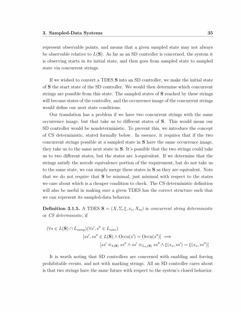
Definition 3.1.5. A TDES S = (X, Σ, ξ, xo, Xm) is concurrent string deterministic
or CS deterministic, if
(∀s ∈ L(S) ∩ Lsamp)(∀s′, s′′ ∈ Lconc)
[ss′, ss′′ ∈ L(S) ∧Occu(s′) = Occu(s′′)] =⇒[ss′ ≡L(S) ss′′ ∧ ss′ ≡Lm(S) ss′′ ∧ ξ(xo, ss
′) = ξ(xo, ss′′)]
It is worth noting that SD controllers are concerned with enabling and forcing
prohibitable events, and not with marking strings. All an SD controller cares about
is that two strings have the same future with respect to the system’s closed behavior.

36 3. Sampled-Data Systems
Following Definition 3.1.5 will ensure our controller is deterministic, but we may end
up with some redundant states that we can later minimize using standard digital logic
techniques [7] for synchronous finite state machines.
For CS deterministic TDES, we now wish to define some of the tools we will need
to express the sampled-data behavior of a TDES. This will be useful when we want to
talk about the behavior of a plant under the control of an SD controller, and compare
it to the TDES behavior of the plant under the control of its TDES supervisor. The
first thing we need to do is define for a given TDES, a next sampling state function.
This will represent how a TDES will move from sampling state to sampling state via
concurrent strings.
Definition 3.1.6. For the CS deterministic TDES S = (X, Σ, ξ, xo, Xm), we define
the partial function, next sampling state function
∆ : Xsamp × Pwr(Σact) → Xsamp
as follows. For x ∈ Xsamp and Σ′ ⊆ Σact,
∆(x, Σ′) :=
ξ(x, s) if (∃s ∈ Lconc)ξ(x, s)! & Occu(s) ∩ Σact = Σ′
undefined otherwise
For the special case Σ′ = ∅, ∆(x, Σ′) can still be defined according to the definition.
It just returns a sampling state x′ = ξ(x, τ), which means that no event except a tick
has occurred during the last sampling period. In analogy to the DES transition
function, we write ∆(x, Σ′)! if ∆(x, Σ′) is defined.
As a precondition for the definition of ∆, we require that the TDES be CS de-
terministic. This means that two concurrent strings with the same occurrence image
will take us to exactly the same state in S. For CS deterministic TDES, this means
that ∆ is well defined.
To see how a non CS deterministic TDES would cause problems, consider Figure
3.1. For this example, let α, β ∈ Σact and xn, x′, x′′ ∈ Xsamp for some TDES S =
(X, Σ, ξ, xo, Xm). In Figure 3.1, part (a) shows the only portion of S that is not
minimized, such that s′ = αβτ and s′′ = βατ end up at two different states, x′ and
x′′ respectively. But (b) shows the minimized version where x′ and x′′ have been

3. Sampled-Data Systems 37
Figure 3.1: Nonminimal Example
merge into a single state x. Clearly in (a), Occu(s′) ∩ Σact = Occu(s′′) ∩ Σact but
ξ(xn, s′) 6= ξ(xn, s′′), which would mean that δ is not well-defined. However in (b),
everything is fine. Another problem would be if x′ and x′′ were not λ-equivalent.
This would mean that we cannot merge the two states, and again δ would not be well
defined.
3.2 SD Controllable Languages
So far, we have required that our TDES system have a finite statespace, be ALF
and nonblocking, that our plant have proper time behavior and be complete for our
supervisor. and that our supervisor be controllable for our plant. However, these
conditions are not sufficient to address the concerns that we raised in Section 1.1. In
particular, we saw that even though the above conditions are met, our actual system
behavior under the control of the corresponding SD controller could block, violate
our control law, or even exhibit behavior not contained in our plant model.
To address these issues, we now introduce a new concept called SD controllable
languages, defined below. Let G = (Q, Σ, δ, q0, Qm) be a TDES where Σ = Σc ∪ Σu for
controllable and uncontrollable events. Of course, for a TDES system, Σc = Σhib∪τ.As we will see, this new condition implies TDES controllability, thus we do not have
to test for this condition separately.

38 3. Sampled-Data Systems
It should be noted that the condition we are presenting is a bit conservative. If
a system fails it, there may be some situations where things are still fine. Our goal
here is to provide a set of conditions that should ensure correct behavior when we
implement our TDES supervisors, and be general and flexible enough to apply to a
wide range of systems, yet be reasonable conditions to evaluate.
Definition 3.2.1. A language K ⊆ Σ∗ is SD Controllable with respect to G =
(Q, Σ, δ, q0, Qm) if, ∀s ∈ K ∩ L(G), the following statements are satisfied:
i) EligL(G)(s) ∩ Σu ⊆ EligK(s)
ii) If τ ∈ EligL(G)(s) then
τ ∈ EligK(s) ⇔ EligK∩L(G)(s) ∩ Σhib = ∅iii) If s ∈ Lsamp then
1. (∀s′ ∈ Σ∗act)[ss
′ ∈ K ∩ L(G)] ⇒[EligK∩L(G)(ss
′) ∪Occu(s′)] ∩ Σhib = EligK∩L(G)(s) ∩ Σhib
2. (∀s′, s′′ ∈ Lconc) [ss′, ss′′ ∈ K ∩ L(G) ∧Occu(s′) = Occu(s′′)] ⇒ss′ ≡K∩L(G) ss′′ ∧ ss′ ≡K∩Lm(G) ss′′
iv) K ∩ Lm(G) ⊆ Lsamp
Point i This is the standard untimed controllability definition and is part of TDES
controllability. Intuitively, any uncontrollable events eligible in G may not be
disabled.
Point ii If both a prohibitable event and tick event are enabled and eligible, it will be
ambiguous in which clock period the event should occur in. Also, a supervisor
must not disable a tick unless there exists a prohibitable (forcible)1 event to
preempt the tick. The if and only if part only applies if the tick event is eligible
in the plant.
The ⇒ part states that a tick event must be disabled by K if there is an eligible
prohibitable event. This is done to ensure that prohibitable events are disabled
1Remember, we have required that the set of prohibitable events be equal to the set of forcibleevents.

3. Sampled-Data Systems 39
until they should occur and then they are immediately forced. In other words, it
means forcing and enabling are essentially one and the same. This is to make it
clear which clock period a prohibitable event should occur in. This in turn will
make translating to an SD controller much simpler and straightforward. Part
of the goal of this definition is to make the behavior specified by the TDES as
close as possible to that which is possible with the actual SD controller. In this
case, the SD controller needs to know exactly when to force an event. A range
of possible clock periods is no good to it.
The ⇐ part states that a tick event cannot be disabled unless there exists an
eligible prohibitable event to preempt the tick. Together with Point i, this is
equivalent to TDES controllability (Definition 2.3.6).
Point iii The following two points are needed when s is a sampled string.
1) This condition says that the set of prohibitable events eligible in K and
L(G) after sampled string s (i.e. immediately after a tick occurs (clock edge))
must stay equal to the union of the prohibitable events still eligible, and the
prohibitable events that have already occurred since the last tick. In other
words, the prohibitable events eligible after the tick must stay eligible until
they occur, and no new prohibitable events may become eligible until after the
next tick.
This condition is meant to capture two concepts. The first is that since an
SD controller only can observe the system at a clock edge (tick event), its en-
ablement and forcing decisions are determined by its current state, and must
be constant until the next tick occurs. These cannot change during the cur-
rent clock cycle in response to events occurring, as it will not know they have
occurred until after the next tick, which would be too late.
The second concept is that an SD controller decides to force an event immedi-
ately after a tick, based on the information it has at that point (i.e. whether
the event is currently enabled and eligible in the plant). Once it decides to force
the event, it will occur at some point during the current clock period. So as
to not violate the control law or the plant model, this event must stay eligible
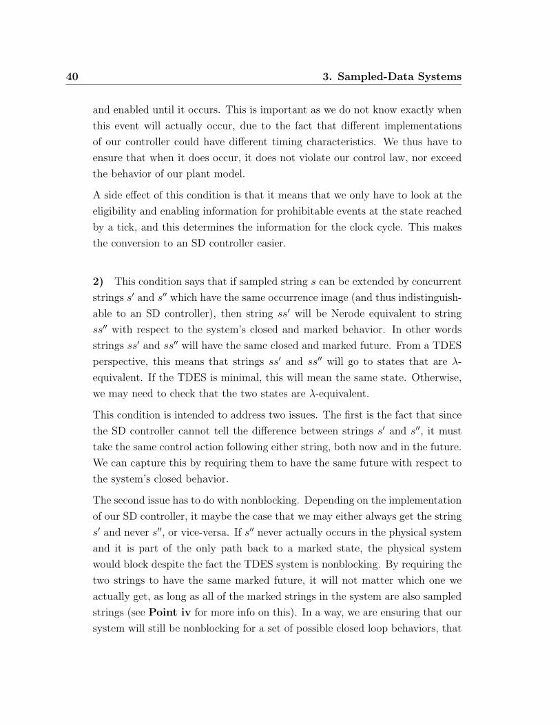
40 3. Sampled-Data Systems
and enabled until it occurs. This is important as we do not know exactly when
this event will actually occur, due to the fact that different implementations
of our controller could have different timing characteristics. We thus have to
ensure that when it does occur, it does not violate our control law, nor exceed
the behavior of our plant model.
A side effect of this condition is that it means that we only have to look at the
eligibility and enabling information for prohibitable events at the state reached
by a tick, and this determines the information for the clock cycle. This makes
the conversion to an SD controller easier.
2) This condition says that if sampled string s can be extended by concurrent
strings s′ and s′′ which have the same occurrence image (and thus indistinguish-
able to an SD controller), then string ss′ will be Nerode equivalent to string
ss′′ with respect to the system’s closed and marked behavior. In other words
strings ss′ and ss′′ will have the same closed and marked future. From a TDES
perspective, this means that strings ss′ and ss′′ will go to states that are λ-
equivalent. If the TDES is minimal, this will mean the same state. Otherwise,
we may need to check that the two states are λ-equivalent.
This condition is intended to address two issues. The first is the fact that since
the SD controller cannot tell the difference between strings s′ and s′′, it must
take the same control action following either string, both now and in the future.
We can capture this by requiring them to have the same future with respect to
the system’s closed behavior.
The second issue has to do with nonblocking. Depending on the implementation
of our SD controller, it maybe the case that we may either always get the string
s′ and never s′′, or vice-versa. If s′′ never actually occurs in the physical system
and it is part of the only path back to a marked state, the physical system
would block despite the fact the TDES system is nonblocking. By requiring the
two strings to have the same marked future, it will not matter which one we
actually get, as long as all of the marked strings in the system are also sampled
strings (see Point iv for more info on this). In a way, we are ensuring that our
system will still be nonblocking for a set of possible closed loop behaviors, that

3. Sampled-Data Systems 41
differ by which of these concurrent strings can actually happen in the physical
system.
Point iv This point says that all marked strings in the closed loop system must be
sampled strings. The primary reason is that sampled strings represent observ-
able points in the system. This makes sure that we do not mark a non empty
strict substring of a concurrent string accepted by the system. We saw in Point
iii.2 that two concurrent strings with the same occurrence image have the same
marked future, but the condition says nothing about Σ+act substrings of these
concurrent strings. Point iii.2 basically says that even if we only get one of
the two concurrent strings, we can still get to a new sampled state with an
equivalent marked future. i.e. we might lose one of the paths to this sampled
state, but we can still get there. However, if we allow marking along the path
between sampled states and that is the path we lose, we may no longer be able
to reach a marked state. Hence, we require all marked strings to take us to
sampled states.
So far, we have only discussed controllable languages. To extend this concept to
a TDES supervisor S = (X, Σ, ξ, xo, Xm), we identify K = Lm(S) and K = L(S)
in Definition 3.2.1.2 This gives us the definition below. Note that the definition is
implicitly assuming that G and S are combined using the meet operator. If instead
we had a plant G′ and supervisor S′ combined using the synchronous product operator
resulting in system event set Σ, we would first construct plant G from G′ by adding
selfloops of any events missing from Σ, and supervisor S from S′ by again adding
needed selfloops. We can then apply the definition below to the these new TDES.
Definition 3.2.2. A supervisor S = (X, Σ, ξ, xo, Xm) is said to be SD controllable
with respect to G = (Q, Σ, δ, q0, Qm) if, ∀s ∈ L(S) ∩ L(G), the following statements
are satisfied:
i) EligL(G)(s) ∩ Σu ⊆ EligL(S)(s)
ii) If τ ∈ EligL(G)(s) then
τ ∈ EligL(S)(s) ⇔ EligL(S)∩L(G)(s) ∩ Σhib = ∅2By “identify,” we mean make the indicated replacements in the original definition to get the
new definition. We do not mean to imply that we require that S be nonblocking.

42 3. Sampled-Data Systems
iii) If s ∈ Lsamp then
1. (∀s′ ∈ Σ∗act)[ss
′ ∈ L(S) ∩ L(G)] =⇒[EligL(S)∩L(G)(ss
′) ∪Occu(s′)] ∩ Σhib = EligL(S)∩L(G)(s) ∩ Σhib
2. (∀s′, s′′ ∈ Lconc) [ss′, ss′′ ∈ L(S) ∩ L(G) ∧Occu(s′) = Occu(s′′)] ⇒ss′ ≡L(S)∩L(G) ss′′ ∧ ss′ ≡Lm(S)∩Lm(G) ss′′
iv) Lm(S) ∩ Lm(G) ⊆ Lsamp
We now discuss a few examples to illustrate the above definition, starting with
Point ii. We do not give an example for Point i or Point iii.2 since the first is
essentially untimed controllability, and the second is similar to the CS Deterministic
property discussed in Section 3.1.
Figure 3.2 shows an example where prohibitable event α and a tick are both
possible at the same state in the plant. When our supervisor decided to enable α
here, Point ii required that tick must be disabled. Also, Point ii only allowed us to
disable tick here as forcible event α was possible in both the plant and supervisor to
preempt the tick.
Figure 3.2: An Example for Point ii
Figure 3.3 shows an example for Point iii.1. In the diagram, we see that the only
prohibitable event possible after the tick is β. We see that β stays possible until it
occurs on both paths, and no new prohibitable events become eligible before the next
tick.
Figure 3.4 shows an example that fails Point iv. Here we see that the state
reached by the first tick is marked which is allowed, but then the state reached by α
is also marked, which is not.
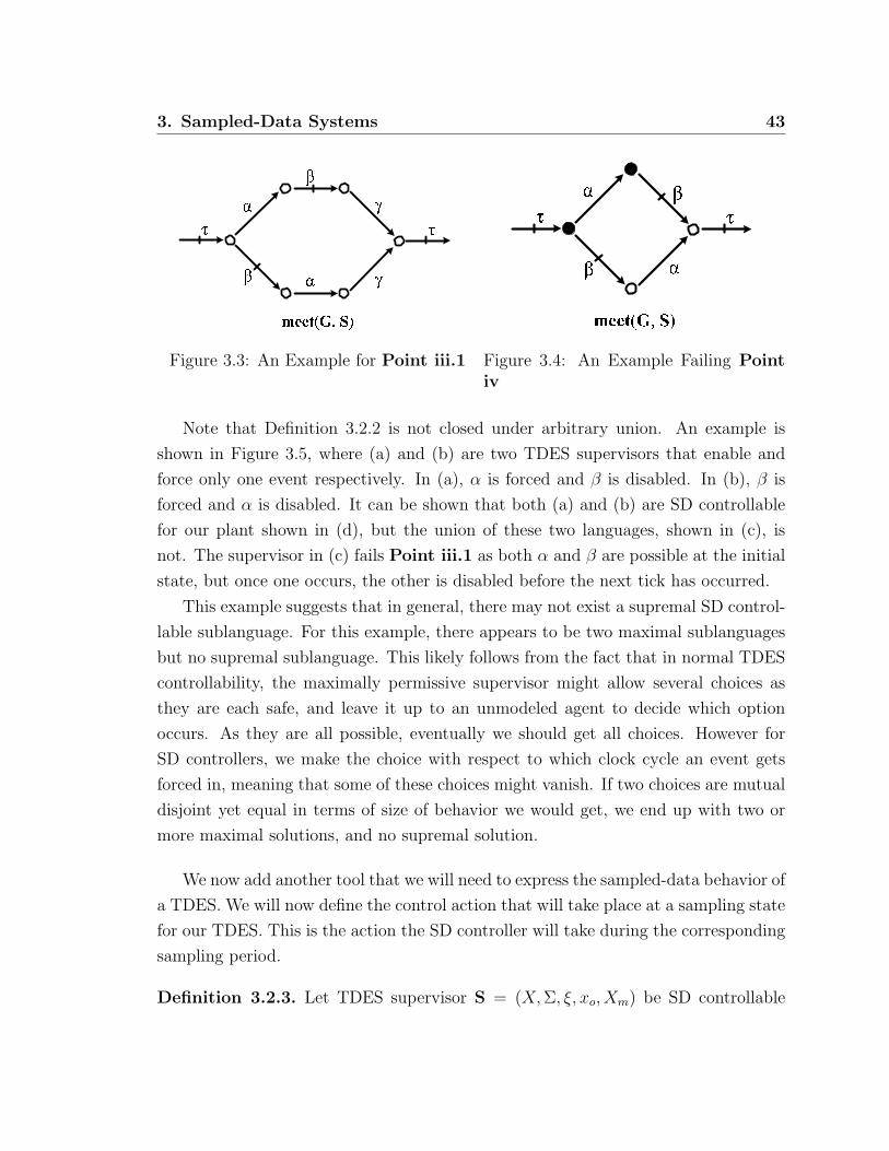
3. Sampled-Data Systems 43
Figure 3.3: An Example for Point iii.1 Figure 3.4: An Example Failing Pointiv
Note that Definition 3.2.2 is not closed under arbitrary union. An example is
shown in Figure 3.5, where (a) and (b) are two TDES supervisors that enable and
force only one event respectively. In (a), α is forced and β is disabled. In (b), β is
forced and α is disabled. It can be shown that both (a) and (b) are SD controllable
for our plant shown in (d), but the union of these two languages, shown in (c), is
not. The supervisor in (c) fails Point iii.1 as both α and β are possible at the initial
state, but once one occurs, the other is disabled before the next tick has occurred.
This example suggests that in general, there may not exist a supremal SD control-
lable sublanguage. For this example, there appears to be two maximal sublanguages
but no supremal sublanguage. This likely follows from the fact that in normal TDES
controllability, the maximally permissive supervisor might allow several choices as
they are each safe, and leave it up to an unmodeled agent to decide which option
occurs. As they are all possible, eventually we should get all choices. However for
SD controllers, we make the choice with respect to which clock cycle an event gets
forced in, meaning that some of these choices might vanish. If two choices are mutual
disjoint yet equal in terms of size of behavior we would get, we end up with two or
more maximal solutions, and no supremal solution.
We now add another tool that we will need to express the sampled-data behavior of
a TDES. We will now define the control action that will take place at a sampling state
for our TDES. This is the action the SD controller will take during the corresponding
sampling period.
Definition 3.2.3. Let TDES supervisor S = (X, Σ, ξ, xo, Xm) be SD controllable

44 3. Sampled-Data Systems
with respect to plant G = (Q, Σ, δ, q0, Qm). The control action ζ : Xsamp → Pwr(Σhib)
is defined for x ∈ Xsamp ⊆ X as follows:
ζ(x) := σ ∈ Σhib|ξ(x, σ)!Proposition 3.1. For TDES supervisor S = (X, Σ, ξ, xo, Xm) which is SD control-
lable with respect to plant G = (Q, Σ, δ, q0, Qm), we have
(∀s ∈ L(S) ∩ Lsamp)ζ(x) = EligL(S)(s) ∩ Σhib
where x = ξ(xo, s).
Proof. This follows immediately from the definition of L(S) and the Elig operator.
Figure 3.5: SD Controllability and Arbitrary Union.
We close this chapter with a proposition pointing out the connection of our CS
deterministic definition and Point iii.2 of the SD controllability definition.
Proposition 3.2. If TDES supervisor S = (X, Σ, ξ, xo, Xm) is SD controllable for
plant G = (Q, Σ, δ, q0, Qm), then meet(S,G) is CS deterministic if it is minimal.
Proof. Follows automatically from Point iii.2 in Definition 3.2.2.
However, an SD controllable supervisor S with respect to plant G does not imply
that S is CS deterministic by itself, because of the dependency of plant G in the
definition of SD controllability. We use the CS deterministic property when we wish
to only discuss the supervisor, instead of the closed loop behavior of the system.
3. Sampled-Data Systems 45
3.3 Future Work
In this thesis, we have presented some new conditions and methods that are intended
to address the concurrency and implementation issues raised in Section 1.1. However,
we only partly dealt with time delay issues which we have left as future work due to
time considerations.
We have tried to mitigate potential time delay problems by the assumptions we
have made at the beginning of Chapter 3. Here, we have required that our controllers
be implemented on a single machine, that they use a common clock, that they all see
the result of a common sampling of the inputs, and that their outputs change at about
the same time. These restrictions should protect against time delay issues caused by a
distributed implementation of controllers, where they could sample inputs at different
times, update enablement information at different times, and this information could
reach the plant at different times.
Another potential time delay problem is the difference between when an event
physically occurs (say a part arrives at a machine), and when a controller sees that
the event has occurred. For instance, the event might physically occur in sampling
period k, but due to transmission delay, it does not reach the input of the controller
until the next clock cycle, so the controller “sees” it one clock cycle late. It is even
possible that the signal could reach the input right at the clock edge, and thus is not
noticed till the next clock edge. All of these issues could cause the system that the
controller “sees” to have slightly different timing information from the formal model.
We have tried to compensate for this by assuming that an event has occurred
when its corresponding input goes true at the controller, with one exception. The
exception is when the input goes true so close to the clock edge, it does not show up
till the next sampling period. In this case, the event is assumed to happen just after
the clock edge. We then model the system with this interpretation of what it means
for an event to occur, in particular with respect to the timing of the events.
Whereas the steps we have taken to compensate for timing delay are not ideal,
they should handle the more pressing issues. However, research needs to be done to
identify the existing timing delay issues, and address them directly in a more flexible
manner.

46 3. Sampled-Data Systems

Chapter 4
Moore Synchronous Finite State
Machines
A Moore state machine is a type of finite state machines introduced by Edward F.
Moore in [17]. It chooses its next states based on its current state and inputs. Its
outputs are determined by its current state only. We will use Moore state machines
with clocked systems whose states change only on a rising or falling edge of the clock.
Its current output remains the same until the state is changed again. A Moore state
machine used in this way is called a Moore Synchronous Finite State Machine. In the
following discussion, we simply use Moore machine or FSM for convenience.
By the properties defined in Chapter 3, an SD Controller can be modeled as a
Moore machine. In the following pages, we will first define a formal model for our
SD controller in Section 4.1. Then, in Section 4.2 we will introduce translations
methods for a centralized controller and for modular controllers. The translation
methods require that the given supervisors be CS deterministic and non-selfloop ALF,
as defined in Section 3.1 and Section 2.3. Note that we can translate a supervisor
as long as its CS deterministic, but it would likely be very hard to evaluate the CS
deterministic condition if the TDES is not ALF or non-selfloop ALF, as we would
essentially have an infinite number of concurrent strings to evaluate. It is also quite
likely such a system would fail the CS deterministic condition. Requiring that the
TDES also be ALF or the weaker non-selfloop ALF makes everything easier, and still
gives us a general solution as a non ALF system is not physically realistic.
47
48 4. Moore Synchronous Finite State Machines
4.1 Formal Model
In this chapter, we will often be discussing vectors of information that will change
periodically with respect to some clock. Let k ∈ 0, 1, 2, ... We will say “at time k”
to indicate the point of time at which k clock ticks have gone by since our starting
reference point, which we represent as k = 0. For any vector v = [v1, v2, ..., vn] ∈ V
or any of its element vj , we write “v(k)” and “vj(k)” to denote the value of v and
vj at time k. Note that v(k) is not a function of k, but a notation to differentiate
the value of v at different points in time. For k = 0, v(0) represents the initial or
starting value of v. When we are discussing an SD controller, we can think of k = 0
as representing the time when the controller has just been turned on.
We can think of when k is incremented as the occurrence of a tick from our clock.
With respect to a TDES system, this would correspond to the occurrence of the tick
event. As such, k induces a sequence for vector v with respect to these clock ticks,
which we define to be v(k)|k = 0, 1, ..., and is denoted as v(k) as a shorthand.
Assumption 4.1. For convenience, we assume every controller is operating based on
the same global clock, so that they change state at the same time.
Given a TDES supervisor S = (X, Σ, ξ, xo, Xm), we will refer to the implementa-
tion of S as its corresponding SD controller. We now give a formal definition of SD
controllers.
Definition 4.1.1. An SD controller C is represented by a Moore machine defined as
follows.
C = (I, Z, Q, Ω, Φ,qres)
where,
I is the set of possible Boolean vectors that the inputs to our controller
can take on. Each vector i ∈ I has v input variables, such that
i = [i0, i1, .., iv−1]; ij ∈ 0, 1; j = 0, 1, .., v − 1

4. Moore Synchronous Finite State Machines 49
Each input vector i(k′) ∈ i(k) is sampled at the occurrence of a tick
event, except for k = 0 which occurs when the controller is turned
on.
Each element of I corresponds to a unique activity event in our sys-
tem. If that element equals “1” at time k, then that means the event
has occurred at least once since that last clock tick. If it equals zero,
then it means the corresponding event has not occurred at all since
the last clock tick.
Z is the set of possible Boolean vectors that the controller outputs can
take on. Each vector z ∈ Z has r output variables, such that
z = [z0, z1, .., zr−1]; zj ∈ 0, 1; j = 0, 1, .., r − 1
Each input vector z(k′) ∈ z(k) is generated at the occurrence of
the tick event, except for k = 0 which occurs when the controller is
turned on. Note that we do not provide separate outputs for forcing,
because the forcing of an event is already implied by enabling the
event.
The values of vector Z represent enablement information for our
prohibitable events. A value of ‘1’ means the event is enabled, while
‘0’ means the event is disabled.
Q is the set of possible Boolean vectors that the state of our controller
can take on. Each vector q ∈ Q has l state variables for state iden-
tification, such that
q = [q0, q1, .., ql−1]; qj ∈ 0, 1; j = 0, 1, .., l − 1
Each state q(k′) ∈ q(k) changes to next state q(k′ + 1) ∈ q(k)at the occurrence of the tick event, starting at k = 1.
qres is the default state when the machine is reset or initialized. We take
q(0) = qres.

50 4. Moore Synchronous Finite State Machines
Ω : Q× I → Q is a next state function which takes the current state
q(k) ∈ Q and an input vector i(k + 1) ∈ I, and returns the next
state q(k + 1) ∈ Q.
q(k + 1) = Ω(q(k), i(k + 1))
Φ : Q → Z is the state to output map. For state q ∈ Q, the output z ∈ Z
at this state is:
z = Φ(q)
A few comments are worthwhile here to clarify our notation. We will discuss the
notation used for states, but the same applies for input and output variables. If we
use q by itself (i.e. q ∈ Q), then it represents a single instance of Q (i.e. some specific
vector of zeros and ones with j elements). When we use q(k′), then this is the k′-th
element of the sequence q(k) where each element of the sequence is some member
of Q. Obviously, we can construct many different possible q(k) sequences. If we
wish to label different sequences, we will use different labels for q, such as q(k) and
q′(k).With respect to our input, a specific sequence i(k) would represent a specific
pattern of inputs we received for a specific run of the system. If we ran the system
again, we could get a completely different sequence. From our definition of C, we see
that our state sequence is completely determined by qres, Ω, and i(k). If we get a
different input sequence, we could get a different state sequence, depending on how
our next state function responds to the input values. As our output is a function of
our current state, this means we could also get a different output sequence as well. In
other words, input sequence i(k) might induce state and output sequences q(k)and z(k), while input sequence i′(k) might induce state and output sequences
q′(k) and z′(k) which may or may not be the same as the other sequences of the
same type..
Example 4.1. Inspired by the DES shown in Figure 2.1, we take Figure 4.1 as an
example to see how to apply our formal SD controller model.
Figure 4.1(a) shows an example of a TDES and Figure 4.1(b) shows the Moore ma-
chine representing this TDES. Our ordering for the input variables is I = [α1, α2, µ1, µ2, β1, λ1]

4. Moore Synchronous Finite State Machines 51
(a) Original TDES
Q=[0, 0]Z=[1,1,0,0]
Reset
DEF
Q=[0, 1]Z=[0,0,0,0]
[1,1,0,0,0,0] [0,0,0,0,1,0]
DEF
Q=[1, 0]Z=[0,0,1,1]
[0,0,0,0,0,1]
[0,0,1,1,0,0]
DEF
(b) FSM Translation (c) Abbreviated FSM
Figure 4.1: FSM Translation Example
and for our outputs is Z = [α1, α2, µ1, µ2]. We have also added a DEF or default
transition to cover input combinations that we have not explicitly specified. The rea-
son is that the transition function for a TDES is a partial function, but that of a FSM
must be a complete function. The actual translation from the TDES in (a) to the con-
troller in (b) will be presented after the translation method for centralized controllers
is introduced in the next section.
In (b), we showed the SD controller for our example in the format of the formal
52 4. Moore Synchronous Finite State Machines
SD controller model we just defined. Typically when we give a diagram of an FSM,
we use the more compact and readable notation shown in Figure 4.1(c). Here we have
given states meaningful names, and we only list at a state those prohibitable events
whose outputs are true (1) at that state. Also, rather than listing input vectors on
transitions, we use boolean equations that are true for the required input vector. We
use ‘!’ as NOT, ‘+’ as OR, and ‘·’ as AND1. We also only use in the equations those
events that could occur at a given state, to simplify the equations.
4.2 Translation Method
To translate a supervisor to Moore FSM, we require that the supervisor be CS deter-
ministic. CS deterministic is necessary because, for SD systems, we lose the ordering
information for the events that occur during a given sampling period. Event sequences
that have the same occurrence image must all go to the same next state in the state
machine implementation or our controller will be nondeterministic. We can ensure
this if we require the supervisors to be CS deterministic before being translated.
We also require that the supervisor be non-selfloop ALF. The reason is to make
sure we have a manageable set of next state conditions. If we have activity loops
that are not selfloops, then our supervisor does not have enough information for us
to determine a reasonable set of concurrent strings to use to define our next state
condition. We would thus potentially have a large choice of strings, most of which
are not possible in the closed loop system. By requiring that the supervisor be non-
selfloop ALF, we should have a reasonable set of possible concurrent strings at a
given state. As we discussed earlier, technically the CS deterministic condition is
strong enough, however, this condition is hard to evaluate if the system is not ALF
or non-selfloop ALF. So, what we would do in practice is first check that our TDES
is ALF or non-selfloop ALF, and if so, we will then check if it is CS deterministic.
We note that we require that a supervisor S be CS deterministic before we can
translate it to a controller, but we do not need the supervisor be SD controllable for
our plant G for the conversion process itself. We also note that if we are translating
S to a controller, the fact that S is SD controllable for G is not sufficient to be able to
1In the following FSM graphs, this operator is represented by ‘.(period)’ instead of ’·’ due to atechnical difficulty.

4. Moore Synchronous Finite State Machines 53
do the conversion, as it implies that S||G is CS deterministic if S||G is minimal, not
S itself. If G is not complete for S, we may wish to instead convert S||G instead of S,
but typically we prefer to construct modular controllers for the component supervisors
that make up S, as they usually are far more compact.
In the following sections, we introduce event mapping functions, and how to trans-
late a CS deterministic TDES supervisor into a centralized controller. We then discuss
the translation of modularized CS deterministic supervisors.
4.2.1 Event Mapping Functions
As we will often be discussing vectors of boolean values whose elements refer to
specific events in Σact, we will need a way to map events to a vector’s elements and
vice versa. Let G = (Y, Σ, δ, yo, Ym) be the TDES plant to be controlled and let
S = (X, ΣS, ξ, xo, Xm) be an arbitrary CS deterministic TDES supervisor for G. We
define Σact ⊂ Σ to be the set of all the activity events and Σhib ⊆ Σact to be the set
of all prohibitable events. We consider Σ, Σact and Σhib to be global event sets that
can always be referred to in the following discussion.
We first define a bijective map between an activity event set and an index set we
will use for labeling the events.
Definition 4.2.1. Let bijective map γg : Σact → 0, .., |Σact| − 1 be the canonical
event mapping function such that
(∀σ1, σ2 ∈ Σact)σ1 = σ2 ⇐⇒ γg(σ1) = γg(σ2)
For the controller implementation C = (I, Z, Q, Ω, Φ,qres) of S, we include its
event mapping information in our translation methods in the following sections, which
are the two event mapping functions defined below. The reason we impose the or-
dering requirement is so that essentially the function γg will induce a single way to
define the mapping functions.
Definition 4.2.2. The input event mapping function for C is defined to be a bijective
map γ : ΣS ∩ Σact → 0, 1, .., v − 1 where v = |ΣS ∩ Σact|. It is defined such that
(∀σ1, σ2 ∈ ΣS ∩ Σact)γg(σ1) < γg(σ2) =⇒ γ(σ1) < γ(σ2)

54 4. Moore Synchronous Finite State Machines
Definition 4.2.3. The output event mapping function for C is defined to be a bijective
map η : ΣS ∩ Σhib → 0, 1, .., r − 1 where r = |ΣS ∩ Σhib|. It is defined such that
(∀σ1, σ2 ∈ ΣS ∩ Σhib)γg(σ1) < γg(σ2) =⇒ η(σ1) < η(σ2)
Since γg is globally available, two input event mapping functions for different
controllers will always have the same mapping pairs for the same event domain. In
other words, because of the ordering requirement, there is only one way to define the
input mapping. Similar logic applies to the output mapping for same event domain.
An example is shown below.
Example 4.2. For different controllers C1 and C2 whose supervisors S1 and S2 are
defined over Σ = Σact ∪ τ = α, β, λ, τ. If γg(α) < γg(β) < γg(λ), then we always
have the input event mapping function γ1 = γ2 = (α, 0), (β, 1), (λ, 2) for C1 and
C2.
Sometimes we want to find out which event an index in an input or output vector
corresponds to. This can be easily done by applying the inverse event mapping
function, since the event mapping functions we have defined are all bijective. i.e. to
find the index of event α in the input event index used by the controller, use γ−1(α).
For event σ ∈ ΣS∩Σact, we can use the inverse event mapping functions to locate
the element in a vector that corresponds to σ. For example, the corresponding element
for σ in the input vector would be iγ−1(σ). For convenience, we may write iσ instead
of iγ−1(σ) and zσ instead of zη−1(σ).
4.2.2 Output Equivalence
If we have two or more controllers for system G, we may wish to determine if they will
produce equivalent output (i.e. enablement information) for the same input sequence.
The problem is that each controller may care about a slightly different event set, thus
we likely cannot use a single i(k) input sequence for them. As defined in our formal
model, for n controllers C1,C2, ...,Cn, each controller Cj for 1 ≤ j ≤ n has its
own input vector ij ∈ Ij and will generate its own output vector based on the input
sequence ij(k) it receives.

4. Moore Synchronous Finite State Machines 55
Before we check that their output sequences are equivalent, we need each input
sequence ij(k) to contain equivalent input information. However, their input vectors
might be incompatible with each other, because their event mapping for the inputs
can be different. Therefore, we will provide a single input vector ig globally available
to every controller, and let each controller extract its own input vector ij from ig.
Essentially, ig represents the inputs the system sees, where each ij represents the
inputs that each controller sees (which may be a strict subset of the system inputs)
and is formatted for the input index that controller is using.
Definition 4.2.4. Let Σact ⊂ Σ be the set of global activity events, we require
ig = [ig,0, ig,1, .., ig,vg−1] to be defined over Σact where vg = |Σact|. That is, for any
event σ ∈ Σact, there is an element in ig corresponds to σ and only σ. We call ig(k)a canonical input sequence and ig ∈ ig(k) a canonical input vector 2.
To extract input vector ij = [ij,0, ij,1, .., ij,vj−1] from ig for controller Cj, for 0 ≤l < vj we have ij,l = ig,l′ where l′ = γg((γ
−1j (l))).
Definition 4.2.5. For j = 1, 2, let Cj = (Ij, Zj, Qj, Ωj, Φj,qres,j) be a controller. We
say C1 and C2 are output equivalent if for any canonical input sequence ig(k) and
induced output zj(k′) = [zj,1(k
′), zj,2(k′), .., zj,rj
(k′)] ∈ Zj at time k′ = 0, 1, 2, . . .,the follow conditions are satisfied.
1. r1 = r2
2. (∀0 ≤ i < r1)η−11 (i) = η−1
2 (i)
3. (∀k′ ∈ 0, 1, ..)z1(k′) = z2(k
′)
In the above definition, by Point 1, 2 we are essentially requiring the outputs of the
two controllers be of the same size, and represent the same events in the same order.
We could have been more general and only required that they represent the same
events but in possibly different order, but this does not gain much and complicates
our notation. In Point 3, we are requiring that one controller enables a prohibitable
event if and only if the other does, for any value of k′. In other words, they agree at
the reset state, and will continue to agree in the future.
2Note that our use of “canonical” here refers to the size and ordering of the inputs, not to theactual values of the input sequence or a given vector.

56 4. Moore Synchronous Finite State Machines
A common situation is that controllers C1 and C2 have been defined relative to
a CS deterministic supervisor S = (X, ΣS, ξ, xo, Xm), and we are only interested that
they generate the same output with respect to input sequences that represent valid
input strings to the supervisor (i.e. s ∈ L(S) ∩ Lsamp). We first provide a definition
for valid input sequences relative to TDES S, and then a form of output equivalence
definition for these sequences.
Definition 4.2.6. For system event set Σ, with canonical event mapping function γg,
activity event set Σact, and CS deterministic TDES supervisor S = (X, ΣS, ξ, xo, Xm),
we say a canonical input sequence ig(k) is input valid for S, if
(∀k ∈ 1, 2, ...)(∃s1, s2, . . . , sk ∈ Lconc)
[s1s2..sk ∈ L(S)]∧ [(∀n ∈ 1, 2, ..., k)(∀σ ∈ Σact) ig,γg(σ)(n) = 1 iff σ ∈ Occu(sn)]
Essentially in the above definition, we are requiring the sequence ig(k) to cor-
respond to a sequence of concurrent strings that supervisor S will accept. We are
specifically excluding input sequences that our supervisor says will never occur. As
we will see in the next section, when we translate a CS deterministic supervisor into
a controller we will define next state information in an arbitrary manner for invalid
input sequences. We will thus not be interested in whether two controllers generate
the same output sequences for invalid input sequences.
We now provide a new output equivalence definition that is only concerned about
input sequences that are valid for our supervisor.
Definition 4.2.7. For system event set Σ, with canonical event mapping function γg,
activity event set Σact, and CS deterministic TDES supervisor S = (X, ΣS, ξ, xo, Xm),
let Cj = (Ij, Zj, Qj, Ωj, Φj,qres,j), j = 1, 2 , be a controller. We say C1 and C2 are
output equivalent with respect to S if for any canonical input sequence ig(k) that
is input valid for S, and induced output zj(k′) = [zj,1(k
′), zj,2(k′), .., zj,rj
(k′)] ∈ Zj at
time k′ = 0, 1, 2, . . ., the follow conditions are satisfied.
1. r1 = r2
2. (∀0 ≤ i < r1)η−11 (i) = η−1
2 (i)
3. (∀k′ ∈ 0, 1, ..)z1(k′) = z2(k
′)

4. Moore Synchronous Finite State Machines 57
4.2.3 Centralized Controller
We will now discuss how to translate a TDES supervisor into a centralized controller.
Let TDES supervisor S = (X, Σ, ξ, xo, Xm) be CS deterministic and non-selfloop
ALF. To translate S into a controller C = (I, Z, Q, Ω, Φ,qres), we need to introduce
a few definitions.
We start by defining how many state variables are needed for Q. Let Xsamp ⊆ X
be the set of sampling states for S. To map each sampling state to a state in the
controller, we define the state size of Q, l, to satisfy 2l−1 < |Xsamp| ≤ 2l. There are l
state variables in vector q ∈ Q. A state in S which is not found in Xsamp, does not
correspond to any state variable assignment in Q.
We now define a function to map the sampling states of our TDES supervisor,
onto states of the controller.
Definition 4.2.8. Let S = (X, Σ, ξ, xo, Xm) be a CS deterministic supervisor. Let
Λ : Xsamp → Q be an arbitrary injective map where Xsamp ⊆ X. We say Λ is a state
mapping function for controller C if, for all x ∈ Xsamp, Λ(x) returns a vector of state
variables q = [q0, q1, .., ql−1] such that,
(∀x1, x2 ∈ Xsamp)Λ(x1) = Λ(x2) ⇐⇒ x1 = x2
Recall that the initial state is also a sampling state, and it is mapped to be
Λ(xo) = qres = q(0).
We now define a function that will map subsets of Σact to a particular assignment
of the variables for I (called a valuation of I) that will represent the events present
in the subset, according to the mapping defined by γ, the controller’s input event
mapping function. This will be useful for taking the occurrence image of a concurrent
string and identifying the corresponding valuation that represents that subset in I.
Definition 4.2.9. Let C = (I, Z, Q, Ω, Φ,qres) be the corresponding controller for
CS deterministic supervisor S = (X, Σ, ξ, xo, Xm). The size of each input vector i ∈ I
is defined to be v = |Σact|.Let γ be the input event mapping function for controller C. Then we have a
bijective map
58 4. Moore Synchronous Finite State Machines
ΓI : Pwr(Σact) → I
defined as follows. For arbitrary ΣI ⊆ Σact, we have ΓI(ΣI) = [i0, i1, .., iv−1] such that
for j = 0, 1, .., v − 1,
ij :=
1 if (∃σ ∈ ΣI)γ(σ) = j
0 otherwise
We call ΓI the input set mapping function for controller C.
The motivation for the above mapping is that at each sampling state, it will
be observed which activity events have occurred, and which have not. Since the
order of event occurrences is not stored, activity events are observed as if they are
concurrent. Thus the occurrence of each event can be represented as a binary value
in the corresponding position of the input vector i.
We now define a function that will map subsets of Σhib to a particular assignment
of the variables for Z that will represent the events present in the subset, according to
the mapping defined by η, the controller’s output event mapping function. This will
be useful for taking the set of prohibitable events eligible at a sampling state of the
supervisor, and identifying the corresponding valuation that represents that subset
in Z.
Definition 4.2.10. Let C = (I, Z,Q, Ω, Φ,qres) be the corresponding controller for
CS deterministic supervisor S = (X, Σ, ξ, xo, Xm). The size of each vector in z ∈ Z
is defined to be r = |Σhib|. Let η be the output event mapping function for controller
C. Then we have a bijective map
ΓZ : Pwr(Σhib) → Z
defined as follows. For arbitrary ΣZ ⊆ Σhib, we have ΓZ(ΣZ) = [z0, z1, .., zr−1] such
that for j = 0, 1, .., r − 1,
zj :=
1 if (∃σ ∈ ΣZ)η(σ) = j
0 otherwise
We call ΓZ the output set mapping function for controller C.
4. Moore Synchronous Finite State Machines 59
We now discuss how to define the next state function Ω for our controller, using
our CS deterministic supervisor as our starting point. Note that the ∆ function was
defined in Section 3.1.
Definition 4.2.11. Let C = (I, Z,Q, Ω, Φ,qres) be the corresponding controller for
CS deterministic supervisor S = (X, Σ, ξ, xo, Xm). Let Xsamp ⊆ X. For state q ∈ Q
and arbitrary input i ∈ I, the next state function Ω is defined to be
Ω(q, i) = Λ(∆(x, Γ−1I (i))) if (∃x ∈ Xsamp)q = Λ(x) & ∆(x, Γ−1
I (i))!
All remaining values of Ω are assigned arbitrarily.
Essentially, we define Ω in terms of ξ, the next state function of TDES S. For
the given state q of our controller and input i which are some valuations of sets Q
and I, we define the next state of the controller to match that of the supervisor. We
define Ω(q, i) arbitrarily unless our state q corresponds to a sampled state x in S,
there exists a concurrent string s whose occurrence image matches the set of activity
events represented by i, and ξ(x, s)! in our supervisor. In that case, our new state is
q′ = Λ(ξ(x, s)) as per the definition of ∆. If there does not exist such an x and s,
that means q and i do not correspond to possible behavior of our system, so we can
define the next state as we like (note ξ is a partial function, but Ω must be a total
function).
In practice, we would not assign the next state randomly. Most likely, we would
choose q′ to either make our controller simpler, or we would choose q′ in a failsafe
manner. By failsafe, we mean that we do not believe the combination q and i should
ever be seen in the physical system, but we will choose our next state in a way to
maximize safety should it actually ever occur.
We now discuss how to define the output map Φ for our controller, using our CS
deterministic supervisor as our starting point. Note that the ζ function was defined
in Section 3.2.
Definition 4.2.12. Let C = (I, Z,Q, Ω, Φ,qres) be the corresponding controller for
CS deterministic supervisor S = (X, Σ, ξ, xo, Xm). Let ζ(x) be the control action for
any sampling state x ∈ Xsamp ⊆ X as defined in Definition 3.2.3. For any q ∈ Q, the
output map Φ is defined to be

60 4. Moore Synchronous Finite State Machines
Φ(q) :=
ΓZ(ζ(x)) if (∃x ∈ Xsamp)q = Λ(x)
ΓZ(∅) otherwise
The definition states that if state q in controller C has a corresponding state
x ∈ Xsamp in S, then Φ(q) specifies an output vector based on the control action ζ(x).
ζ(x) is equal to the set of prohibitable events enabled at state x in S. Otherwise,
Φ(q) leaves all prohibitable events disabled at state q.
Let TDES S = (X, Σ, ξ, xo, Xm) be a CS deterministic supervisor. Then Figure 4.2
shows the control equivalence diagram for S and its controller C = (I, Z, Q, Ω, Φ,qres),
as defined in this section. If, for arbitrary Σ′ ⊆ Σact and state x ∈ Xsamp of S, ∆(x, Σ′)
is defined, it is easy to see that this diagram commutes.
Figure 4.2: Centralized Control Equivalence Diagram
Essentially, the diagram says that as long as ∆(x, Σ′)!, then ΓZ(ζ(∆(x, Σ′))) =
Φ(Ω(Λ(x), ΓI(Σ′)) meaning that we can just use the next state function and output
map of the controller, and we will produce the correct enablement. Note that the
Σ′ represent the occurrence image (minus tick) of the concurrent strings defined at
the given sampled state. The figure also says that if ∆(x, Σ′)!, then Λ((∆(x, Σ′))) =
Ω(Λ(x), ΓI(Σ′), meaning that we can simply use the controller’s next state function
to determine the correct next state.

4. Moore Synchronous Finite State Machines 61
Example 4.3. Let C = (I, Z, Q, Ω, Φ,qres) be represented by the Moore machine
shown in Figure 4.1(b). We see from Figure 4.1(a), that our set of activity events is
α1, α2, β, µ1, µ2, λ, and our set of prohibitable events are α1, α2, µ1, µ2. We can
also see that the TDES is ALF, and CS deterministic.
We have each i ∈ I in the form of
i = [i0, i1, i2, i3, i4, i5]
For j = 0, 1, .., 5, ij corresponds to the occurrence of events [α1, α2, µ1, µ2, β, λ] re-
spectively, when ij = 1.
We have each z ∈ Z in the form of
z = [z0, z1, z2, z3]
For j = 0, 1, .., 3, zj corresponds to the enablement of prohibitable events [α1, α2, µ1, µ2],
when zj = 1.
We see from Figure 4.1(a) that our TDES has three sampled states. Our state
size, l, must thus satisfy 2l−1 < 3 ≤ 2l. As only l = 2 satisfies this equation, our state
set must have two binary elements. We thus have each q ∈ Q in form of
q = [q0, q1]
We will let state (q0, q1) ∈ (0, 0), (0, 1), (1, 0) represent states I, W,D respectively.
The fourth state (1, 1) is unused and will be unreachable, so we can define transition
leaving this state arbitrarily.
Examining Figure 4.1(a), we can determine which concurrent strings are defined
at each sampled state. For instance, at state I we could only get strings α1α2τ or
α2α1τ . Both have occurrence image α1, α2, τ and take us to sampled state W . As
this subset corresponds to i = [1, 1, 0, 0, 0, 0], we can see where the transition at state
(0,0) in Figure 4.1(b) comes from. Continuing this logic, we can derive the remaining
transitions for the SD controller shown in Figure 4.1(b). Note, that we have added
the DEF default transitions as we discussed in Section 4.1.
Next,
qres = q(0) = [0, 0]

62 4. Moore Synchronous Finite State Machines
Using the information we have derived for Figure 4.1(b), we can define the next
state function, Ω, as below:
q(k + 1) =Ω(q(k), i(k + 1)) = Ω([q0(k), q1(k)], [i0(k + 1), i1(k + 1), .., i5(k + 1)])
such that
Ω([0, 0], [1, 1, 0, 0, 0, 0]) = [0, 1]
Ω([0, 0], i) = [0, 0] for all other i ∈ I
Ω([0, 1], [0, 0, 0, 0, 1, 0]) = [0, 0]
Ω([0, 1], [0, 0, 0, 0, 0, 1]) = [1, 0]
Ω([0, 1], i) = [0, 1] for all other i ∈ I
Ω([1, 0], [0, 0, 1, 1, 0, 0]) = [0, 0]
Ω([1, 0], i) = [1, 0] for all other i ∈ I
and Ω([1, 1], i), for any i ∈ I, can be defined arbitrarily as state [1, 1] is unreachable.
Lastly, we define the output function to be
z = Φ(q)
such that
Φ([0, 0]) = [1, 1, 0, 0]
Φ([0, 1]) = [0, 0, 0, 0]
Φ([1, 0]) = [0, 0, 1, 1]
We can define Φ([1, 1]) arbitrarily, say Φ([1, 1]) = [0, 0, 0, 0].
The execution of a centralized controller C is as follows.
1. Initialize the controller by setting q(0) = qres, z = Φ(qres). We have k = 0.
2. At the next clock pulse
i) sample inputs and set i(k + 1) equal to these values.
ii) calculate our new state and output as follows:
i.e. q(k + 1) = Ω(q(k), i(k + 1)) and z(k + 1) = Φ(q(k + 1))
4. Moore Synchronous Finite State Machines 63
3. Set k = k + 1. Go to step 2.
We say C acts on G when controller C enables or disables events from plant G.
Also, since an SD controller forces a prohibitable event as soon as its enabled, the
controller is also forcing these events to occur in that clock period. To be consistent, if
any controller C is discussed from now on, we will assume that it has been converted
from some CS deterministic supervisor S, using the translation method defined in
this section.
Before we close this section, we would like to briefly discuss the case that our TDES
supervisor S is defined over a subset ΣS of the system event set, Σ. This would mean
that some activity events would not affect the next state of the controller and could
be ignored, thus simplifying the next state logic of the controller. The output for the
controller would still cover all events in Σhib. The difference would be that for all
σ ∈ Σhib − ΣS, their corresponding output would always be set to 1.
4.2.4 Modular Controllers
For large systems, the centralized supervisor for the system is quite likely large and
complex. This would mean that its corresponding controller would also be large and
complex, making implementing it directly undesirable. Just as we design modular
TDES supervisors for systems to make the design more manageable, we can also
implement our controllers by directly translating these modular supervisors into their
own controllers. We can then combine the outputs of these controllers together,
to create the overall output that would be equivalent to the output provided by a
centralized controller.
To implement the composition of modular controllers, we need the following two
operations on vectors.
Definition 4.2.13. Let V be the set of Boolean vectors with each vector of size n.
For u = [u1, u2, .., un],v = [v1, v2, .., vn] ∈ V , the logical AND operator ∧ : V ×V → V
is
u ∧ v = [u1 ∧ v1, u2 ∧ v2, .., un ∧ vn].
64 4. Moore Synchronous Finite State Machines
Definition 4.2.14. Let u be a Boolean vector of i variables, and v be another
Boolean vector of j variables. The concatenation operator . : V × V → V is defined
as follows.
u.v = [u1, u2, .., ui, v1, v2, .., vj]
For convenience, we will often just write uv instead.
Let the TDES S = S1||S2||..||Sn be a supervisor where each modular supervisor
Si, for 1 ≤ i ≤ n, is CS deterministic.
To avoid implementing the likely large S directly, we wish to implement each
supervisor Si as controller Ci, then combine the controllers C1,C2, ..,Cn (referred to
as the composite controller) to generate the actual final output. We call each Ci the
modular controller for supervisor Si. To be able to reuse the implementation technique
discussed in the previous section, we assume each supervisor Si is CS deterministic.
When comparing a centralized controller implementation to a modular controller
implementation, all we care about is the output equivalence of the centralized con-
troller and the composite controller created from C1,C2, ...,Cn. If we take S and
implement it directly as a controller C, we want the composition of the outputs from
C1,C2, ..,Cn to be equivalent to the output from C.
We will now discuss how to implement the modular supervisors as individual
controllers, and then combine them into a composite controller to handle the system.
It is key to note that the modular supervisors may be defined over strict subsets of the
system event set, Σ. Essentially, supervisor Sj will have activity event set Σact,j ⊆ Σact
and prohibitable event set Σhib,j ⊆ Σhib. To translate the CS deterministic supervisor
Sj to a controller, we will use the method defined in Section 4.2.3, but the key
difference is that we replace every Σact in the definitions with Σact,j, and each Σhib
with Σhib,j. This means that the input and the output sets for the controller may
only represent a subset of Σact and Σhib, respectively.
Definition 4.2.15. Let G be the plant to be controlled, γg be the canonical event
mapping function, Σ be the system event set, Σact the system activity event set, and
Σhib the prohibitable event set. For j = 1, 2, .., n, let Sj = (Xj, Σj, ξj, xo,j, Xm,j) be the
j-th CS deterministic supervisor, where Σj = Σact,j∪τ ⊆ Σ. Here we have Σact,j ⊆

4. Moore Synchronous Finite State Machines 65
Σact the activity event set for supervisor Sj, Σhib,j ⊆ Σhib the prohibitable event set
for Sj. We also require that Σ =⋃
j∈1,2,..,nΣj. Then we define the composition of
modular controllers as follows.
Let Cj = (Ij, Zj, Qj, Ωj, Φj, qres,j) be the controller for Sj with the following con-
figuration:
• lj is the number of state variables for each qj = [qj,0, qj,1, .., qj,lj−1] ∈ Qj
• vj = |Σact,j| is number of input variables for each ij = [ij,0, ij,1, .., ij,vj−1] ∈ Ij
• rj = |Σhib,j| is number of output variables for each zj = [zj,0, zj,1, .., zj,rj−1] ∈ Zj
The composition of C1,C2, ..,Cn,
C = (I, Z, Q, Ω, Φ, qres) = comp(C1,C2, ..,Cn)
is defined as follows.
1. Σact =⋃
j=1,2,..,n
Σact,j and Σhib =⋃
j=1,2,..,n
Σhib,j, thus Σhib ⊆ Σact ⊂ Σ is guaran-
teed.
2. The number of state variables for vectors q ∈ Q is defined to be l =∑n
j=1 lj.
The state vector q is defined to be
q = q1q2..qn
= [q1,0, q1,1, .., q1,l1−1][q2,0, q2,1, .., q2,l2−1]..[qn,0, qn,1, .., qn,ln−1]
= [q1,0, q1,1, .., q1,l1−1, q2,0, q2,1, .., q2,l2−1, .., qn,0, qn,1, .., qn,ln−1]
3. The size of each input vector i ∈ I is defined to be v = |Σact|.Then we define γ : Σact → 0, 1, .., v−1 to be the input event mapping function
for C such that
(∀σ1, σ2 ∈ Σact)γg(σ1) < γg(σ2) =⇒ γ(σ1) < γ(σ2)
4. The size of each output vector z ∈ Z is defined to be r = |Σhib|.Then we define η : Σhib → 0, 1, .., r − 1 to be the output event mapping
function for C such that
(∀σ1, σ2 ∈ Σhib)γg(σ1) < γg(σ2) =⇒ η(σ1) < η(σ2)

66 4. Moore Synchronous Finite State Machines
5. The next state function Ω : Q × I → Q is defined such that, for q(k) =
q1(k)q2(k)..qn(k) ∈ Q and i(k + 1) ∈ I,
q(k + 1) = Ω(q(k), i(k + 1))
= Ω1(q1(k), i1(k + 1)) Ω2(q2(k), i2(k + 1)) .. Ωn(qn(k), in(k + 1))
For above, the input vector i(k + 1) is in canonical form with respect to γg.
To use it as an input to each controller Cj, we need to map it to input vector
ij(k + 1) using γj, the input event mapping function for Controller Cj. To do
this, we need to map input vector
i(k + 1) = [i0(k + 1), i1(k + 1), .., iv−1(k + 1)]
onto input vectors ij(k+1) = [ij,0(k+1), ij,1(k+1), .., ij,vj−1(k+1)] for modular
controller Cj, as follows
(∀σ ∈ Σact,j)ij,γj(σ)(k + 1) = iγg(σ)(k + 1)
6. The output map Φ : Q → Z is defined as follows.
Given q = q1q2..qn ∈ Q, let
zj = Φj(qj) = [zj,0, zj,1, .., zj,rj−1] ∈ Zj
For each zj we expand it to
z′j = [z′j,0, z′j,1, .., z
′j,r−1] ∈ Z
such that,
(∀σ ∈ Σhib)z′j,η(σ) =
zj,ηj(σ) if σ ∈ Σhib,j
1 otherwise
In above, ηj is the output event mapping for controller Cj. Essentially, what
we are doing is mapping the output value for Cj to the corresponding position
in z′j if σ ∈ Σhib,j, else we always set the value equal to 1.

4. Moore Synchronous Finite State Machines 67
With expanded output vectors z′1, z′2, .., z
′n ∈ Z defined, the next state function
is then defined to be
Φ(q) =∧
j∈1,2,..,nz′j
We simply logically AND each z′j together to obtain the output vector.
In Definition 4.2.15, we assumed that when the supervisors are combined together,
they are defined over Σ, the systems event set (i.e.⋃
j=1,2,..,n
Σj). As for the centralized
supervisor, it may be the case that the supervisors only care about a subset of Σ. This
would mean that some activity events would not affect the next state of the controller
and could be ignored, thus simplifying the next state logic of the controller. The
output for the composite controller would still cover all events in Σhib. The difference
would be that for all σ ∈ Σhib but not covered by any modular supervisor, their
corresponding output would always be set to 1.
We now present a theorem that shows that we can either implement our supervisor
centrally or modularly, and we will get the same enablement information for valid
input sequences.
Theorem 4.1. Let G be the plant to be controlled, γg be the canonical event mapping
function, Σ be the system event set, Σact the system activity event set, and Σhib the
prohibitable event set. Also, let CS deterministic supervisor S = (X, Σ, ξ, xo, Xm) be
composed of n component CS deterministic supervisor Sj = (Xj, Σj, ξj, xo,j, Xm,j) for
j = 1, 2, .., n, such that S = S1||S2||..||Sn. Let Σact,j ⊆ Σact and Σhib,j ⊆ Σhib be the
activity event set and prohibitable event set for Sj.
For j = 1, 2, .., n, let Cj = (Ij, Zj, Qj, Ωj, Φj,qres,j) be the controller translated
from Sj using translation method defined in Section 4.2.3 but replacing every Σact in
the definitions with Σact,j, and each Σhib with Σhib,j. Let C′ = comp(C1,C2, ..,Cn)
be the composed controller of C1,C2, ..,Cn. Let C = (I, Z,Q, Ω, Φ,qres) be the
controller translated from S using the translation method defined in Section 4.2.3.
Then C and C′ are output equivalent with respect to S.
Proof. Assume the required initial conditions for the proof.

68 4. Moore Synchronous Finite State Machines
Next, we need to define the following items for our proof, to ensure clarity.
Let Xsamp ⊆ X and Xsamp,j ⊆ Xj be the sets of sampling states for S and Sj,
respectively.
Let ∆ : Xsamp × Pwr(Σact) → Xsamp and ∆j : Xsamp,j × Pwr(Σact,j) → Xsamp,j be
the next sampling state functions for S and Sj, respectively.
Let Λ : Xsamp → Q and Λj : Xsamp,j → Qj be the state mapping functions for C
and Cj, respectively.
Let ΓI : Pwr(Σact) → I and ΓI,j : Pwr(Σact,j) → Ij be the input set mapping
functions for C and Cj, respectively.
Let ΓZ : Pwr(Σhib) → Z and ΓZ,j : Pwr(Σhib,j) → Zj be the output set mapping
functions for C and Cj, respectively.
Let γ : Σact → 0, 1, .., v−1, γ′ : Σact → 0, 1, .., v′−1, γj : Σact,j → 0, 1, ..vj−1be the input event mapping functions for C, C′, and Cj, respectively. We note that
since γ and γ′ have domain Σact, they must both equal γg due to how they are defined
i.e. given a specific γg, there is only one way to define the other two functions and it
must be the same as γg, if Definition 4.2.2 is to be satisfied. (1)
Let η : Σhib → 0, 1, .., r−1, η′ : Σhib → 0, 1, ..r′−1, ηj : Σhib,j → 0, 1, ..rj−1be the output event mapping functions for C, C ′, and Cj, respectively. We note that
since η and η′ have domain Σhib, they must be equal due to how they are defined (see
Definition 4.2.3). This means that Z and Z ′ represent the same prohibitable events,
in the same order, and can be directly compared. (2)
Given the above setting, we will now show that C and C′ are output equivalent
with respect to S.
Let i(k′′) be a canonical input sequence with respect to γg, the canonical event
mapping function for the system, and let the sequence be input valid with respect to
S. From (1), we have γ = γ′ = γg. This means that i(k′′) can be used as an input
for both C and C′ directly, without any mapping required.
Let z′(k) = [z′1(k), z′2(k), .., z′r′(k)] ∈ Z ′ be the induced output vector in C′ at time
k, from input sequence i(k′′).Let z(k) = [z1(k), z2(k), .., zr(k)] ∈ Z be the induced output vector in C at time
k, from input sequence i(k′′).

4. Moore Synchronous Finite State Machines 69
We now need to show the following three points from Definition 4.2.7.
1. Show r′ = r
As both C and C′ are defined relative to Σ, their outputs are both defined rela-
tive to Σhib. It follows immediately from the definition of r′ and r in Definition
4.1.1 that r′ = r.
2. Show (∀0 ≤ i < r) η(i) = η′(i)
Let i ∈ 0, 1, .., r − 1, show η(i) = η′(i).
This follows immediately from (2).
3. Show (∀k ∈ 0, 1, ..) z(k) = z′(k)
(A) First we will show that if C is in state q = Λ(x) for some x ∈ Xsamp,
and each Cj is in state qj = Λj(xj) for some xj ∈ Xsamp such that x =
(x1, x2, .., xn), then C at state q and C′ at state q1q2..qn will have the
same output.
(B) Then we will show for all k ∈ 0, 1, .. that after inputs i(1), i(2), .., i(k)
from our input sequence i(k′′), C will be in state q(k) = Λ(x(k)) for
some x(k) ∈ Xsamp, and Cj will be in state qj(k) = Λj(xj(k)) for some
xj(k) ∈ Xsamp,j such that x(k) = (x1(k), x2(k), .., xn(k)).
Combining the two points will give the desired result.
Claim A: We will now prove point (A).
Let C be in state q = Λ(x) for some x ∈ Xsamp.
Let each Cj be in state qj = Λj(xj) for some xj ∈ Xsamp,j.
Assume x = (x1, x2, .., xn).
We thus have C′ at state q′ = q1q2..qn.
Let z = Φ(q) and z′ = Φ′(q′). Must show z′ = z.
By Definition 4.2.12 of the output map, we have for C that Φ(q) = ΓZ(ζ(x))
70 4. Moore Synchronous Finite State Machines
The set of prohibitable events enabled at q can be represented as
ΣZ =ζ(x)
=σ ∈ Σhib|ξ(x, σ)! by definition of ζ(x)
=⋂
j∈1,2,..,nσ ∈ Σhib|(σ /∈ Σj) ∨ (ξj(xj, σ)!)
by definition of synchronous product
We next note that by point (1) and (2), C and C′ represent exact the same
events in Σhib in exactly the same order. It is sufficient to show that C′ enables
the same event as C.
By Definition 4.2.15, we have
z′ = Φ′(q′) =∧
i∈1,2,..,nz′j
where z′j is the expanded output from controller Cj.
As defined, an event is enabled in z′j if the event is enabled in zj = Φj(qj), or
the event is not in Σhib,j and thus not in Σj. Otherwise, the event is disabled.
Therefore, the set of events enabled by z′j can be represented as
Σ′Z,j =ζj(xj) ∪ Σhib − Σhib,j
=σ ∈ Σhib|(σ /∈ Σj) ∨ (ξ′j(xj, σ)!) by definition of ζj(xj)
The set of events enabled by z′ and thus C′ can be represented as
Σ′Z =
⋂
j∈1,2,..,nΣ′
Z,j
=⋂
j∈1,2,..,nσ ∈ Σhib|(σ /∈ Σj) ∨ (ξj(xj, σ)!)
=ΣZ
Claim A proven.
Claim B: We will now prove point (B).

4. Moore Synchronous Finite State Machines 71
We first consider k = 0
By definition, q(0) = qres = Λ(xo) and for each Cj, qj(0) = qres,j = Λj(xo,j)
We next note that initial states are always sampled states, so we have x(0) = xo
and xj(0) = xo,j. Also, xo = (xo,1, xo,2, .., xo,n) by definition of the synchronous
product. We note that input i(0) is ignored as the controller always starts at
its reset state.
We now consider k ∈ 1, 2, ..As i(k′′) is input valid for S, we know by definition that:
(∀k ∈ 1, 2, ...)(∃s1, s2, . . . , sk ∈ Lconc) [s1s2..sk ∈ L(S)]∧[(∀t ∈ 1, 2, ..., k)(∀σ ∈ Σact)ig,γg(σ)(t) = 1 ⇔ σ ∈ Occu(st)] (3)
This implies that for t ∈ 1, 2, .., k, Occu(st) = Γ−1I (i(t))
We thus have ∆(x(0), Γ−1I (i(1))) = x(1) ∈ Xsamp.
We note that as S is CS deterministic, x(1) = ξ(xo, s1) as any concurrent string
with same occurrence image would come to the same state. We thus have
x(2) = ∆(x(1), Γ−1I (i(2))) with x(2) = ξ(xo, s1s2) ∈ Xsamp and so on, until we
have x(k) = ∆(x(k − 1), Γ−1I (i(k))) with x(k) = ξ(xo, s1s2..sk) ∈ Xsamp.
Let Pj : Σ∗ → Σ∗j , where j = 1, 2, .., n, be a natural projection.
By (3) and definition of the synchronous product, it follows that for t ∈ 1, 2, .., k,Occu(Pj(st)) = Γ−1
I,j(ij(t)) and Pj(s1)Pj(s2)..Pj(st) ∈ L(Sj)
By a similar logic as above, we have
∆j(x(0), Γ−1I,j(ij(1)))
=xj(1)
=ξj(xo,j, Pj(s1)) ∈ Xsamp,j
until we get
xj(k) =∆j(x(k − 1), Γ−1I,j(ij(k)))
with xj(k) = ξj(xo,j, Pj(s1)Pj(s2)..Pj(sk)) ∈ Xsamp,j
By Definition 4.2.11 for Ω, it is easy to see that (∀t ∈ 1, 2, .., k)q(t) = Λ(x(t))
and qj(t) = Λj(xj(t)).

72 4. Moore Synchronous Finite State Machines
By definition of the synchronous product
x(k) =ξ(xo, s1s2..sk)
=(ξ1(xo,1, P1(s1)P1(s2)..P1(sk)),
ξ2(xo,2, P2(s1)P2(s2)..P2(sk)), ..,
ξn(xo,n, Pn(s1)Pn(s2)..Pn(sk)))
=(x1(k), x2(k), .., xn(k)) as required.
Claim B proven.
Let k ∈ 0, 1, ..We are now ready to show that z(k) = z′(k)
We next note that by Claim B, that after inputs i(0), i(1), . . . i(k) from i(k′′),controller C is in state q(k) = Λ(x(k)) for some x(k) ∈ Xsamp and each Cj is in
state qj(k) = Λj(xj(k)) for some xj(k) ∈ Xsamp,j and x(k) = (x1(k), x2(k), .., xn(k)).
We can now apply Claim A with q = q(k) and each qj = qj(k) for j = 1, 2, .., n,
and conclude that for C at state q(k) and C′ at state q1(k)q2(k)..qn(k), they
will produce the same output. In other words, z(k) = z′(k), as required.
By steps 1., 2., and 3., we can thus conclude that C and C′ are output equivalent
with respect to S.
Chapter 5
Control and Nonblocking
Verification
A controller is more constrained than a supervisor. Every time an event occurs, the
supervisor changes its state, but a controller reacts only on sampling instances (tick
event). This means it is possible that the enablement information from the controller
may not always be exactly the same as that of the supervisor’s, as a supervisor can
be more expressive in this regard. We want to make sure that the corresponding en-
ablement information that the controller applies to the plant is such that the system’s
closed loop behavior (the actual behavior of the plant reacting to the controller’s en-
ablement information and the event forcing initiated by the controller) stays a subset
of the desired behavior specified by the supervisor.
5.1 Supervisory Control Construction
First we have the following definition from [6].
Definition 5.1.1. A TDES supervisory control for G = (Y, Σ, δ, yo, Ym) is any map
V : L(G) → Pwr(Σ), such that,
(∀s ∈ L(G))V (s) ⊇
Σu ∪ (τ ∩ EligL(G)(s)) if V (s) ∩ EligL(G)(s) ∩ Σhib = ∅Σu if V (s) ∩ EligL(G)(s) ∩ Σhib 6= ∅
From now on, we will just use the term supervisory control when it is clear by our
context that we are referring to TDES.
73

74 5. Control and Nonblocking Verification
We will be requiring that prohibitable events can only occur at most once per
sampling period. This is to simplify things a bit, but is primarily as we only decide
to force an event once per clock cycle, it makes sense that the event only occurs once
per clock cycle. If the controller has full control over when the event occurs, this is
what will happen so the TDES behavior should reflect this. It makes it easier to keep
track of things. Also, Point iii.1 of the SD controllability definition does not say
anything about eligibility of Σhib events after they have occurred once. As we will see
in the proofs in this section, this assumption will be a key part in making the proofs
work.
Definition 5.1.2. For TDES G = (Y, Σ, δ, yo, Ym), we say that G has singular pro-
hibitable behavior if,
(∀s ∈ L(G) ∩ Lsamp)(∀s′ ∈ Lconc)ss′ ∈ L(G)
=⇒ (∀σ ∈ Occu(s′) ∩ Σhib)(∃s1, s2 ∈ (Σact − σ)∗)s′ = s1σs2τ
In other words, the above condition says that for TDES G, a prohibitable event
is allowed to occur at most once per sampling period.
If TDES G is our plant and TDES S is our supervisor, we likely only care about
checking this condition for strings in L(S) ∩ L(G). We thus introduce the definition
below. An example that fails the S-singular prohibitable behavior property is shown
in Figure 5.1. Here we see the prohibitable event α occurring twice in a sampling
period.
Definition 5.1.3. For TDES G = (Y, Σ, δ, yo, Ym) and TDES S = (X, Σ, ξ, xo, Xm),
we say that G has S-singular prohibitable behavior if
(∀s ∈ L(S) ∩ L(G) ∩ Lsamp)(∀s′ ∈ Σ∗act)ss
′ ∈ L(S) ∩ L(G)
=⇒ (∀σ ∈ Occu(s′) ∩ Σhib) σ 6∈ EligL(G)(ss′)
Figure 5.1: An Example Failing S-singular Prohibitable Behavior Property
Let G = (Y, Σ, δ, yo, Ym) be a TDES plant. For the rest of this chapter, we will
require plant G to be complete for our supervisor S, have proper time behavior and

5. Control and Nonblocking Verification 75
S-singular prohibitable behavior, and that meet(G,S) be ALF. This will ensure that
for any string s ∈ L(G) (or L(V/G) if G is not ALF on its own), we will always be
able to reach a state where tick is possible after at most a finite number of activity
events. In other words, we will not “stop the clock.” This is important as it ensures
that after every sampled string in our system has occurred, all new behavior can be
represented as a series of concurrent strings.
Definition 5.1.4. We write V/G to represent G = (Y, Σ, δ, yo, Ym) under the su-
pervision of V . The closed behavior of V/G is defined to be L(V/G) ⊆ L(G) such
that
1. ε ∈ L(V/G);
2. if s ∈ L(V/G), σ ∈ V (s) and sσ ∈ L(G), then sσ ∈ L(V/G);
3. no other strings are in L(V/G).
It follows from the above definition, that L(V/G) is prefix closed.
Let supervisor S = (X, Σ, ξ, xo, Xm) be CS deterministic and SD controllable
with respect to our plant G. Let C = (I, Z, Q, Ω, Φ,qres) be a centralized controller
translated from S using the method described in Section 4.2.3, with input and output
event mapping functions γ (see Definition 4.2.2) and η (see Definition 4.2.3), and input
and output set mapping functions ΓI (see Definition 4.2.9) and ΓZ (see Definition
4.2.10).
To verify that our controller C will generate the correct enablement information
for our plant, we construct the corresponding supervisory control V for G. The idea is
to express the enablement information that the controller would provide to the plant
as a supervisory control. In particular, we wish to capture the idea that enablement
information only changes after a tick, and then stays constant till the next tick. We
also want to express the forcing information the controller provides to the plant, in
particular the fact that as soon as a prohibitable event is enabled, the controller will
force the event to occur within the current sampling period.
The construction of our supervisory control V will be presented as an algorithm.
We will use the logic in the algorithm to do the verification. First, we need to have the
following definition. An important aspect of sampled strings is that they delineate

76 5. Control and Nonblocking Verification
the concurrent behavior of G, which interprets how G moves from one sampling state
to another.
Definition 5.1.5. For TDES G = (Y, Σ, δ, yo, Ym), the concurrent behavior of G is
defined to be a map CBG : L(G) ∩ Lsamp → Lconc, such that for s ∈ L(G) ∩ Lsamp,
CBG(s) := s′ ∈ Lconc|ss′ ∈ L(G)It states that the possible concurrent behavior for a TDES G after sampled string
s ∈ L(G)∩Lsamp, is the set of concurrent strings that can extend s to a string in the
closed behavior of G.
We now discuss our conversion algorithm, labeled Algorithm 5.1. Given G and the
controller C acting on G, our algorithm constructs our supervisory control map V ,
by keeping track of how our controller changes state in response to strings generated
by our plant. In our next section, we will show the map V is well defined. We first
describe some variables that we will use in our algorithm.
Pend ⊆ Lsamp ×Q is the set of pending (s,q) pairs to be analyzed, where
s is a sampled string in L(G), and q is the corresponding state
in the controller that the sequence of inputs that would match the
concurrent strings that make up s, unless of course s = ε. If s = ε,
then q would be our reset state.
ΣV is the set of prohibitable events enabled by V (s), for current sampled
string s that we are processing.
Σtemp is a copy of ΣV that we make when we are processing a concurrent
string that extends the sampled string, s, that we are currently pro-
cessing. This will be used to keep track of which prohibitable events
in ΣV have not yet occurred in substrings of the concurrent strings
that extend s in L(G).
Next, we will explain the statements in Algorithm 5.1 in detail. Note that Algo-
rithm 5.1 may never terminate as the language L(G) may not be finite, thus giving us
a non-finite number of string-state pairs to evaluate. The algorithm merely describes
abstractly how map V is related to controller C. We will then use this to compare
the control behavior of V to that of our supervisor, S, that C was translated from.
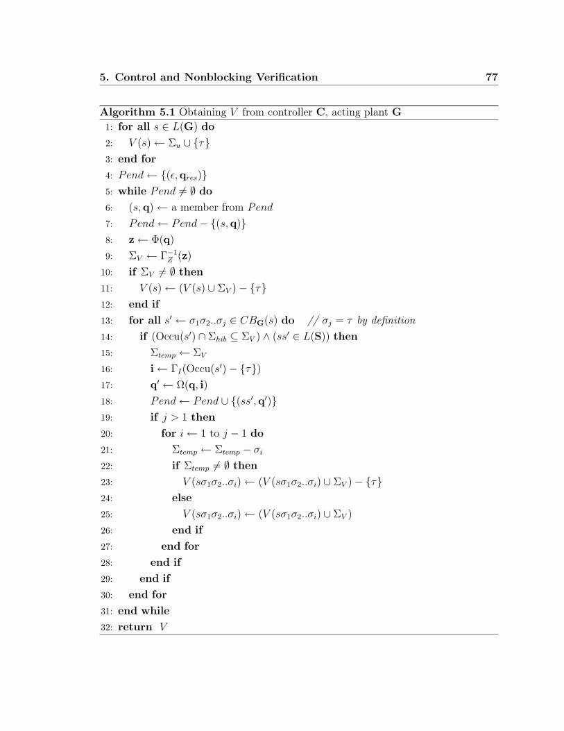
5. Control and Nonblocking Verification 77
Algorithm 5.1 Obtaining V from controller C, acting plant G
1: for all s ∈ L(G) do
2: V (s) ← Σu ∪ τ3: end for
4: Pend ← (ε,qres)5: while Pend 6= ∅ do
6: (s,q) ← a member from Pend
7: Pend ← Pend− (s,q)8: z ← Φ(q)
9: ΣV ← Γ−1Z (z)
10: if ΣV 6= ∅ then
11: V (s) ← (V (s) ∪ ΣV )− τ12: end if
13: for all s′ ← σ1σ2..σj ∈ CBG(s) do // σj = τ by definition
14: if (Occu(s′) ∩ Σhib ⊆ ΣV ) ∧ (ss′ ∈ L(S)) then
15: Σtemp ← ΣV
16: i ← ΓI(Occu(s′)− τ)17: q′ ← Ω(q, i)
18: Pend ← Pend ∪ (ss′,q′)19: if j > 1 then
20: for i ← 1 to j − 1 do
21: Σtemp ← Σtemp − σi
22: if Σtemp 6= ∅ then
23: V (sσ1σ2..σi) ← (V (sσ1σ2..σi) ∪ ΣV )− τ24: else
25: V (sσ1σ2..σi) ← (V (sσ1σ2..σi) ∪ ΣV )
26: end if
27: end for
28: end if
29: end if
30: end for
31: end while
32: return V

78 5. Control and Nonblocking Verification
Initially, the for-loop from line 1 to line 3 includes all events σ ∈ Σu ∪ τ in
V (s) for all s ∈ L(G), to ensure all uncontrollable events are eligible in V (s). This
is needed to satisfy the controllability definition. This is the default setting for each
possible string s. The tick event will be removed later, if we are suppose to be forcing
an event.
A controller always starts operating at its reset state, so this will be the first state
we will examine. As this corresponds to the empty string, our starting place is thus
the tuple (ε,q). On line 4, we thus initialize our set of pending tuples to (ε,q).
The set Pend contains all the state-string pairs that have not been analyzed, and
its members will be extracted one by one in the while-loop running from line 5 to
line 31. There are two parts in the while-loop, where we process V (s) and then
V (sσ1σ2..σi) for i < |s′|, s′ ∈ CBG(s).
At line 6 in the while-loop, a member (s,q) is extracted from the set Pend.
This is the next tuple to be analyzed.
At line 8 output vector z is obtained from the current controller state q by
applying output function Φ. Vector z represents all the prohibitable events that the
controller enables while it is at state Q. Then at line 9, all the prohibitable events
enabled by the controller at current state q are included in ΣV . This is done by using
the inverse of the output set mapping function Γ−1Z (q) from Definition 4.2.10.
At line 11 the enablement information ΣV is included in V (s) for current sampled
string s. As mentioned, the tick event included at line 2 is removed here in accordance
to Point ii of the SD controllability definition (Definition 3.2.2). Basically, it says
if we have eligible prohibitable events enabled, we must disable a tick and force the
event. Of course, when we later show that the map V we have defined is indeed a
TDES supervisor control, we will have to show that these prohibitable events were
eligible in L(G) at this point.
The for-loop from line 13 to line 30 loops through all possible concurrent strings
s′ = σ1σ2..σj ∈ CBG(s) (i.e. those that can extend s in L(G)). First, it calculates
the input vector, i, that would correspond to s′ occurring. This is done by using the
controller’s input event mapping function, ΓI . We then use the controller’s next state
function, Ω, to calculate q′, the state reached from q by input vector i. Recall that
CBG(s) from Definition 5.1.5 is the concurrent behavior at state δ(yo, s) in G.
At line 14, we ignore concurrent strings whose occurrence images contain pro-

5. Control and Nonblocking Verification 79
hibitable events that are not in ΣV . The reason is that these events have been disabled
by the controller, so this represents behavior that will not occur in the closed loop
system, so we just leave it at the default enablement information specified at line 2.
We also ignore concurrent strings that do not represent behavior in L(S), thus
restricting the strings we can change from their line 2 defaults, to strings in L(S) ∩L(G). The reason is that we later need to prove that our V satisfies Definition 5.1.1.
We will do this later by first showing that L(V/G) = L(S)∩L(G), and then use the
fact that S is SD controllable for G.
At line 15, all prohibitable events in ΣV are copied to Σtemp, which stores pro-
hibitable events in ΣV that have not yet occurred in this sampling period. At line
18, the new string-state pair (ss′,q′) is added to set Pend.
At line 19, the if statement checks if s′ contains events other than tick. Since
the only tick event in a concurrent string is the ending event, it only checks if j > 1
for j = |s′|. If so, we execute lines 20 to 27.
In the inner most loop from line 20 to line 27, we analyze each substring σ1σ2..σi,
i < j.
For lines 22 to line 26, if there are still prohibitable events in Σtemp that have
not yet occurred, the map V (sσ1σ2..σi) has to remove the tick event since in our
setting, enabling a prohibitable event also means we want to force it. Otherwise we
leave the tick event in V (sσ1σ2..σi). In either case, we add ΣV to V (sσ1σ2..σi) since
the enablement information of a controller is constant until the next tick event.
In the rest of the chapter, when we are discussing a system with plant G, and CS
deterministic TDES supervisor S that is SD controllable for G, we will be concerned
about the SD controller C that is constructed from S using the translation method
described in Section 4.2, and TDES supervisory control V 1 that is constructed from
C using Algorithm 5.1.
Definition 5.1.6. For plant G, and CS deterministic supervisor S that is SD control-
lable for G, let C be the SD controller that is constructed from S using the translation
method described in Section 4.2, and V be the map that is constructed from C using
1We still need to prove that our map V is indeed a TDES supervisory control, and that the mapis well defined. We will prove this in the following sections.

80 5. Control and Nonblocking Verification
Algorithm 5.1. The marked behavior of V/G is defined to be
Lm(V/G) := L(V/G) ∩ Lm(S) ∩ Lm(G)
We say V is nonblocking for G if
Lm(V/G) = L(V/G)
That is, a nonblocking supervisory control V for G can always reach a marked
state in both G and S by extending the current string s ∈ L(V/G).
5.2 Map V Is Well Defined
We want to show that the map V constructed using Algorithm 5.1 is well defined for
any possible string s ∈ L(G) so that it can be considered as a possible supervisory
control.
For example, Let TDES G be a plant defined over Σ = α, β, γ, ω, τ where
τ = tick. Let Σhib = α, β, γ. Let C be the controller acting on G. Imagine a part
of G as shown in Figure 5.2.
Figure 5.2: Part of a TDES plant
In the figure, let s ∈ L(G) be the string taking us to the left most sampling state.
We see there are two concurrent strings s′1 = αβγωτ and s′1 = αβωγτ extending s in
different paths so that ss′1, ss′2 ∈ L(G). Let s = αβ to be the prefix of both s′1 and
s′2. Since Algorithm 5.1 will evaluate V (ss) twice (lines 22 to 26), we want to make
sure each time V (ss) is assigned the same control action for both paths in the figure.
We also need to make sure that every string s ∈ Lsamp ∩ L(G) is either evaluated
once, or is always associated with the same state q of the controller. We then have
the following proposition to be proven.
5. Control and Nonblocking Verification 81
Proposition 5.1. For plant G = (Y, Σ, δ, yo, Ym), and CS deterministic supervisor
S = (X, Σ, ξ, xo, Xm) that is SD controllable for G, let C be the SD controller that is
constructed from S using the translation method described in Section 4.2.3, and V be
map that is constructed from C using Algorithm 5.1. Then, map V is well defined.
Proof. Assume initial conditions for proposition.
To show that V is well defined, we need to show that for every s ∈ L(G), our
algorithm will define V (s) in only one way.
From the definition of Algorithm 5.1, it is clear that for all s 6∈ L(S) ∩ L(G) ∩ Lsamp,
the algorithm only defines V (s) exactly once on line 2.
This means we only have to examine strings s ∈ L(S) ∩ L(G) ∩ Lsamp.
Let s ∈ L(S) ∩ L(G) ∩ Lsamp.
Further examination of Algorithm 5.1 shows that V (s) is only updated on line
11, line 23 and line 25, if at all.
Examining these cases, we see that if s ∈ Lsamp, it will only be updated at line
11. Otherwise, it could be updated once or more at line 23 or line 25.
Case A) s ∈ Lsamp
We first note that we only care about sampled strings that are added to Pend. If
s is never added to Pend, it is only defined at line 2 and is never updated, thus is
uniquely defined. We can thus assume that s is added at some point to Pend, without
loss of generality.
To show that there is only one way to define V (s), it is sufficient to show that
whenever line 11 was executed for s, ΣV was always the same. Clearly, as long as
ΣV is the same, then executing line 11 again will produce the same result as the
first time. As ΣV is uniquely defined by state q of controller C, it is thus sufficient
to show that string s will always be paired with state q.
If s = ε, then by definition this is always paired with state qres. Studying the
algorithm, it is easy to see this is the case. We thus need only consider the case of
s ∈ Σ∗.τ .
Examining Algorithm 5.1, we can see that every such string in Pend, is constructed
by concatenating one or more concurrent strings together.

82 5. Control and Nonblocking Verification
For s, we thus have:
(∃n ∈ 1, 2, ..)(∃s1, s2, .., sn ∈ Lconc)s1s2..sn = s
As Lconc = Σ+act.τ , there is only way to define strings s1 to sn.
Examining line 16 and line 17 of the algorithm, we see how starting with qres,
each new state would be calculated using the next concurrent string in the list. Ex-
amining the definition of ΓI and Ω from Section 4.2.3, and ∆ from Section 3.1, we can
see that since supervisor S is CS deterministic and s ∈ L(S)∩Lsamp, this sequence of
states is unique, meaning the final state q associated with s is unique for controller
C.
We thus conclude that we will always associate the same state q with s, thus the
same set ΣV .
Case B) s 6∈ Lsamp
This implies (∃t ∈ Lsamp)(∃t ∈ Lconc)t < s < tt
We note that this implies (∃j > 1)(∃σ1, σ2, .., σj ∈ Σ)t = σ1σ2..σj
We thus have (∃i ∈ 1, 2, .., j − 1)tσ1, σ2, .., σi = s
Note that in above, we have j > 1 since as t < s < tt, j = 0, 1 would cause a
contradiction. Basically, j = 0 would mean t = ε, thus tt = t and we could not have
t < s < t. If we had j = 1, we would have t = τ as t ∈ Lconc. As we require t < s, s
must contain at least one event more than t, but that would not also allow s < tt as
t only contains one event. We thus must have j > 1.
We note if for all such t they fail the condition on line 14, or if t was never added
to Pend, then V (s) will never be updated again, and will retain the value it was
assigned on line 2. Thus, with no loss of generality, we can assume that t was added
to Pend and our t passes the condition on line 14. We thus have t, tt ∈ L(S)∩L(G).
Given the definition of Lconc and sampled strings, it is easy to see that there is
only one way to define σ1, σ2, .., σi, and thus sampled string t.
From Part A, we saw that for a given sampled string, there is only one way to
define the corresponding ΣV set. Of course, it is possible that there are multiple ways
to define σi+1..σj.
Examining Algorithm 5.1, we see that the portion that we are concerned with
corresponds to line 19 to line 28. Examining these lines, we see that the definition
of V (s) is determined only by ΣV and tσ1, σ2, .., σi, which are unique for s.

5. Control and Nonblocking Verification 83
It thus follows that V (s) is unique defined for our s.
By Case A and Case B, we have shown that V is well defined.
5.3 Supervisory Control and SD Supervisors
Given the map V constructed from C by Algorithm 5.1, we want show that the closed
loop behavior L(V/G) equals the behavior of meet(G,S), i.e.
L(V/G) = L(S) ∩ L(G)
By Definition 5.1.4 for L(V/G), we find that ε ⊆ L(V/G) ⊆ L(G). We thus
need to make sure that L(G) 6= ∅. This is automatic as long as G has an initial state.
Theorem 5.1. For plant G = (Y, Σ, δ, yo, Ym), and CS deterministic supervisor S =
(X, Σ, δ, xo, Xm) that is SD controllable for G, let both TDES have finite statespaces,
let G be complete for S, have proper time and S-singular prohibitable behavior,
let meet(G,S) be ALF, let C = (I, Z, Q, Ω, Φ,qres) be the SD controller that is
constructed from S using the translation method described in Section 4.2.3, and let
V be the map that is constructed from C using Algorithm 5.1. Then,
L(V/G) = L(S) ∩ L(G)
Proof. Assume assumptions in proposition setup.
To show L(V/G) = L(S) ∩ L(G), we must
1. show L(V/G) ⊆ L(S) ∩ L(G)
2. show L(V/G) ⊇ L(S) ∩ L(G)
To show 1, must show 1.1 and 1.2 as follows.
1.1 show L(V/G) ⊆ L(G)
This is automatic by Definition of L(V/G) and the fact G contains an initial
state.

84 5. Control and Nonblocking Verification
1.2 show L(V/G) ⊆ L(S)
To show this, we must show
(∀s ∈ L(V/G))s ∈ L(S) (1)
Let s ∈ L(V/G). We can show it by induction as follows.
base case s = ε.
As S contains an initial state, it follows that ε ∈ L(S).
inductive step We assume that s = σ1..σk ∈ L(V/G) ∩ L(S) and sσk+1 ∈L(V/G) for some k ≥ 0. We will now show this implies that
sσk+1 ∈ L(S)
Since Σ = Σu ∪ Σc = Σu ∪ Σhib ∪ τ by definition of TDES, we have 3
cases for σk+1 ∈ Σ
(i) σk+1 ∈ Σu
As sσk+1 ∈ L(V/G), it follows that σk+1 ∈ EligL(G)(s) ∩ Σu As S is
SD controllable for G, it follows that σk+1 ∈ EligL(S)(s), thus sσk+1 ∈L(S)
(ii) σk+1 = τ
To show τ ∈ EligL(S)(s), by Point ii in Definition 3.2.2 of SD control-
lability (since S is SD controllable for G) we need to show
(τ ∈ EligL(G)(s)) ∧ (EligL(S)∩L(G)(s) ∩ Σhib = ∅)
Since L(V/G) ⊆ L(G) as shown in 1.1, we have
τ ∈ EligL(V/G)(s)
=⇒ τ ∈ EligL(G)(s)
Now we need to show
EligL(S)∩L(G)(s) ∩ Σhib = ∅

5. Control and Nonblocking Verification 85
By default, the tick event is included in V (s) at line 2. In the algo-
rithm, tick is only removed if ΣV 6= ∅ at line 11 or Σtemp 6= ∅ at line
23.
We thus have four possibilities: a) s ∈ Lsamp, ΣV = ∅ and s was
added to Pend, b) s 6∈ Lsamp, Σtemp = ∅, and V (s) is re-evaluated c)
s ∈ Lsamp and s was not added to Pend, or d) s 6∈ Lsamp and V (s) is
not re-evaluated. We now examine these cases.
(ii.a) s ∈ Lsamp, ΣV = ∅, and s was added to Pend.
As s ∈ Lsamp, either it is the empty string, or s ∈ Σ∗.τ . For the
case s = ε, we have Λ(xo) = qres (see Definition 4.2.8), which
matches the state-string association that Algorithm 5.1 makes.
Otherwise, s is composed of one or more concurrent strings. We
thus have
(∃n ∈ 1, 2, ..)(∃s1, s2, .., sn ∈ Lconc)s1s2..sn = s
As Lconc = Σ+act.τ , there is only way to define strings s1 to sn.
Based on the definitions from Section 4.2.3, we can determine the
state in C that will correspond to string s, by starting with qres,
and evaluating
Ω(qres, ΓI(Occu(s1)− τ)) = q1
As S is CS deterministic, it follows from the definitions of ΓI and
Ω that q1 = Λ(x1), where x1 = ξ(xo, s1). Note that we have
s1 ∈ L(S) as the language is closed.
By the same logic we have
Ω(q1, ΓI(Occu(s2)− τ)) = q2
and q2 = Λ(x2), where x2 = ξ(xo, s1s2).
86 5. Control and Nonblocking Verification
Extending this logic to the end, we have
Ω(qn−1, ΓI(Occu(sn)− τ)) = qn
and qn = Λ(xn), where xn = ξ(xo, s1s2..sn). To simplify the nota-
tion, we will take q = qn and x = xn.
We thus have q the state the controller C will be in after string
s, and x ∈ Xsamp the state that S will be in, while q = Λ(x). It
is easy to see by the logic of Algorithm 5.1, that string s will be
paired with state q. See proof of Proposition 5.1 for more details.
We next note that the outputs at state q are z = Φ(q). We thus
have by Definition 4.2.12 that z = ΓZ(ζ(x)).
By the definition of control action given in Definition 3.2.3, it
follows that ζ(x) = σ ∈ Σhib|ξ(x, σ)!. As ΣV = Γ−1Z (z) as per
line 9 of Algorithm 5.1, we thus have ΣV = σ ∈ Σhib|ξ(x, σ)!.As we have ΣV = ∅ by assumption, we thus have
σ ∈ Σhib|ξ(x, σ)! = ∅
which implies
EligL(S)(s) ∩ Σhib = ∅ as ξ(xo, s) = x
=⇒ EligL(S)∩L(G)(s) ∩ Σhib = ∅
as required.
Part (ii.a) complete.
(ii.b) s 6∈ Lsamp, Σtemp = ∅ and V (s) is re-evaluated.
As V (s) is re-evaluated and s /∈ Lsamp, then it follows from the
logic of Algorithm 5.1 that
(∃t ∈ Lsamp ∩ L(S) ∩ L(G))(∃t ∈ Lconc)
(t < s < tt) ∧ (tt ∈ L(S) ∩ L(G)) (1)
5. Control and Nonblocking Verification 87
It also follows that:
(∃l ∈ 1, 2, ..)(∃σ1, σ2, .., σl ∈ Σact ⊂ Σ) tσ1σ2..σl = s
Now, from the logic of part (ii.a), we know that string t will
be paired in Pend with a state q, such that q = Λ(x), where
x = ξ(xo, t). We thus have
ΣV = EligL(S)(t) ∩ Σhib
=⇒ EligL(S)∩L(G)(t) ∩ Σhib ⊆ ΣV
We now note that as S is SD controllable for G, we have by Point
iii.1 of Definition 3.2.2,
[EligL(S)∩L(G)(s) ∪Occu(σ1σ2..σl)] ∩ Σhib
= EligL(S)∩L(G)(t) ∩ Σhib ⊆ ΣV
⇒ (EligL(S)∩L(G)(s) ∪Occu(σ1σ2..σl)) ∩ Σhib ⊆ ΣV
⇒ EligL(S)∩L(G)(s) ∩ Σhib ⊆ ΣV (2)
It follows from the logic of Algorithm 5.1 and fact that Σtemp = ∅,that
Occu(σ1σ2..σl) ∩ Σhib ⊇ ΣV
In other words, every prohibitable event in ΣV has occurred at
least once since t (i.e. this sampling period).
As t ∈ L(S) ∩ L(G) by (1), and G has S-singular prohibitable
behavior by our initial assumptions, it follows that the prohibitable
events in ΣV cannot occur again in t (i.e. not until after next tick).
This implies
EligL(G)(s) ∩ ΣV = ∅Since EligL(S)∩L(G)(s) ∩ Σhib ⊆ ΣV by (2), it follows that
EligL(S)∩L(G)(s) ∩ Σhib = ∅as required.
Part (ii.b) complete.

88 5. Control and Nonblocking Verification
(ii.c) s ∈ Lsamp and s not added to Pend
We will show that s ∈ Lsamp causes a contradiction and thus s
must be added to Pend. This means that case (ii.a) represents
the only valid possibility, if s ∈ Lsamp
We note that Lsamp = Σ∗.tick ∪ ε. If s = ε, then we know ε is
always added to Pend (line 4 of Algorithm 5.1), so this section
does not apply. We can thus assume s 6= ε, and thus s ∈ Σ∗.τ
Our goal is to show that s will always be added to Pend, thus
(ii.c) never applies.
As s ∈ Σ∗.τ , if follows
(∃n ∈ 1, 2, ..)(∃s1, s2, .., sn ∈ Lconc)s1s2..sn = s
To show that s must be added to Pend, we need to show:
(∀l ∈ 1, 2, . . . , n)(s1s2..sl ∈ L(S) ∩ L(G)) ∧ (Occu(sl) ∩ Σhib ⊆ ΣV (s1s2..sl−1))
where ΣV (s1s2..sl−1) is the value of ΣV at line 14 in the algorithm
when sampled string s1s2..sl−1 is being evaluated.
Let l ∈ 1, 2, . . . , n.
As s ∈ L(S)∩L(G) by assumption, and L(S) and L(G) are closed
languages, s1s2..sl ∈ L(S) ∩ L(G) is automatic.
All that remains is showing
Occu(sl) ∩ Σhib ⊆ ΣV (s1s2..sl−1)
We know from part (ii.a) that sampled string s1s2..sl−1 will always
be paired with state q of the controller, with q = Λ(x), where x =
ξ(xo, s1s2..sl−1). This state q is the state the controller will be in
after this string, thus ΣV (s1s2..sl−1) will be the enablement output
(as per definition of Algorithm 5.1) of the controller until after the
5. Control and Nonblocking Verification 89
next tick occurs. That means for all σ ∈ Σhib − ΣV (s1s2..sl−1), σ
will be disabled until after concurrent string sl has occurred. As
s ∈ L(V/G) by assumption, we also have s1s2..sl ∈ L(V/G) as
L(V/G) is closed and s1s2..sl ≤ s. This means sl cannot contain
any events in Σhib − ΣV (s1s2..sl−1), thus
Occu(sl) ∩ Σhib ⊆ ΣV (s1s2..sl−1)
We have thus shown that for s = ε or s ∈ Σ∗.τ , it must have been
added to Pend. This means that (ii.c) does not apply to s at all,
so string s must be covered by case (ii.a).
Part (ii.c) complete.
(ii.d) s /∈ Lsamp and V (s) is not re-evaluated.
We now examine case of s /∈ Lsamp and show that it must have
been re-evaluated at line 23 or line 25, thus case (ii.b) is the
only valid possibility for s /∈ Lsamp.
As s /∈ Lsamp, it follows that: (∃t ∈ Lsamp)(∃t ∈ Lconc)t < s < tt
It also follows that
(∃l ∈ 1, 2, ..)(∃σ1, σ2, .., σl ∈ Σact ⊂ Σ) tσ1σ2..σl = s (3)
To show that V (s) must have been re-evaluated at line 23 or line
25, it is sufficient to show that t must be added to Pend, and that
there exist a t that will pass the condition on line 14.
We first note that as s ∈ L(S) ∩ L(G), it follows that t ∈ L(S) ∩L(G) as L(G) and L(S) are closed languages. Similarly, as s ∈L(V/G), we also have t ∈ L(V/G).
We can thus apply the logic from (ii.c), and conclude that t must
be added to Pend, and it will be paired with state q of the con-
troller with q = Λ(x) where x = ξ(xo, t). State q is the state the

90 5. Control and Nonblocking Verification
controller will be in after string t, thus ΣV will be the enablement
output of the controller, where
ΣV = EligL(S)(t) ∩ Σhib (4)
We now need to show:
(∃t ∈ Lconc)
(s < tt) ∧ (tt ∩ L(S) ∩ L(G)) ∧Occu(t) ∩ Σhib ⊆ ΣV
We start by constructing a string t ∈ Lconc that satisfies the first
two conditions.
We note that by assumption, G and S have finite statespaces,
G has proper time behavior, meet(G,S) is ALF, and that S is
controllable for G (this is implied by fact S is SD controllable for
G). We can thus apply Proposition 2.4 and conclude
(∃s′ ∈ Σ∗)ss′τ ∈ L(S) ∩ L(G)
We can thus take t = σ1σ2..σls′τ and we have s < tt (by (3)) and
tt ∈ L(S) ∩ L(G).
All that remains is to show
Occu(t) ∩ Σhib ⊆ ΣV
From (4), we have
ΣV = EligL(S)(t) ∩ Σhib
=⇒ EligL(S)∩L(G)(t) ⊆ ΣV
We now note that as S is SD controllable for G, we have by Point
iii.1 of Definition 3.2.2
(∀t′ ∈ Σ∗act)(t
′ < t) =⇒[EligL(S)∩L(G)(tt
′)∪Occu(t′)]∩Σhib = EligL(S)∩L(G)(t)∩Σhib ⊆ ΣV
5. Control and Nonblocking Verification 91
If we take t′ = σ1σ2..σls′ < t we have
[EligL(S)∩L(G)(tt′) ∪Occu(t′)] ∩ Σhib ⊆ ΣV
=⇒ Occu(t′) ∩ Σhib ⊆ ΣV
As t′τ = t, we thus have Occu(t) ∩ Σhib ⊆ ΣV
We have now shown, that for s /∈ Lsamp, we must have re-evaluated
V (s) at line 23 or line 25, so (ii.d) does not apply. This means
that string s must be covered under (ii.b).
Part (ii.d) complete.
We thus have shown by (ii.a-d), that
EligL(S)∩L(G)(s) ∩ Σhib = ∅ ∧ τ ∈ EligL(G)(s)
=⇒ τ ∈ EligL(S)(s) by Point ii of Definition 3.2.2
=⇒ sσk+1 ∈ L(S)
(iii) σk+1 ∈ Σhib
For s ∈ L(S)∩L(G) and s ∈ L(V/G), we know there exists t ∈ Lsamp
and t′ ∈ Σ∗act such that s = tt′.
From (ii.a), we know that Algorithm 5.1 will pair sampled string t
with state q in the controller, with q = Λ(x), where x = ξ(xo, t).
Also, we have
ΣV = EligL(S)(t) ∩ Σhib
⇒ EligL(S)∩L(G)(t) ∩ Σhib ⊆ ΣV
We now will show that σk+1 ∈ ΣV .
We note that as sσk+1 ∈ L(V/G), we have σk+1 ∈ V (s).
From line 2, we see V (s) is initially set to Σu ∪τ. This means that
σk+1 must have been added at line 11 if t′ = ε and t = s, or at line

92 5. Control and Nonblocking Verification
23 or line 25. In either case it implies our prohibitable event is in
ΣV .
We thus have
σk+1 ∈ ΣV =⇒ σk+1 ∈ EligL(S)(t)
=⇒ σk+1 ∈ EligL(G)(t) as G is complete for S. (5)
As S is SD controllable for G, we have from Point iii.1 of Definition
3.2.2 that
[EligL(S)∩L(G)(tt′) ∪Occu(t′)] ∩ Σhib = EligL(S)∩L(G)(t) ∩ Σhib (6)
We note that as sσk+1 ∈ L(V/G), we have sσk+1 ∈ L(G). As G has S-
singular prohibitable behavior, this implies σk+1 has not yet occurred
in this sampling period. Thus
σk+1 /∈ Occu(t′) (7)
From (5), we have σk+1 ∈ EligL(S)∩L(G)(t).
From (6), we thus have
σk+1 ∈ [EligL(S)∩L(G)(tt′) ∪Occu(t′)]
As σk+1 /∈ Occu(t′) from (7), it follows that
σk+1 ∈ EligL(S)∩L(G)(s) (as tt′ = s)
=⇒ sσk+1 ∈ L(S) as required
By (i), (ii) and (iii), we have shown sσk+1 ∈ L(S) for any σk+1 ∈ Σ, thus
our inductive step is complete.
Thus by our base case and our inductive step, we have s ∈ L(S) for arbitrary
s ∈ L(V/G). Therefore, 1.2 is complete.
By step 1.1 and 1.2, we have shown L(V/G) ⊆ L(S) ∩ L(G).
5. Control and Nonblocking Verification 93
2. Show L(V/G) ⊇ L(S) ∩ L(G)
Let s ∈ L(S) ∩ L(G). We need to show this implies
s ∈ L(V/G)
We will show this using proof by induction.
base case s = ε
Automatic that s ∈ L(V/G), by Definition 5.1.4 for L(V/G).
inductive step We assume that s = σ1σ2..σk ∈ L(V/G)∩L(S)∩L(G) and sσk+1 ∈L(S) ∩ L(G) for some k ≥ 0.
We will now show this implies sσk+1 ∈ L(V/G).
Sufficient to show σk+1 ∈ V (s) by Definition of L(V/G), and fact we already
have sσk+1 ∈ L(G)
Again, since Σ = Σu ∪ Σhib ∪ τ by definition of TDES, we have 3 cases for
σk+1 ∈ Σ.
(i) σk+1 ∈ Σu
This is automatic by line 2 in Algorithm 5.1, where all uncontrollable
events are included in V (s) for each possible string s by default. Examining
the algorithm, it is clear that uncontrollable events are never later removed.
(ii) σk+1 = τ
As we have sτ ∈ L(G) and S is SD controllable for G by assumption, we
can conclude by Point ii in Definition 3.2.2 that
τ ∈ EligL(S)(s) ⇐⇒ EligL(S)∩L(G)(s) ∩ Σhib = ∅
As we have sτ ∈ L(S) by assumption, we thus have
EligL(S)∩L(G)(s) ∩ Σhib = ∅ (8)
=⇒ EligL(S)(s) ∩ Σhib = ∅ as G is complete for S (9)

94 5. Control and Nonblocking Verification
Essentially, G complete for S means that if a prohibitable event was ac-
cepted by S, it must also be accepted by G, thus in L(S) ∩ L(G). Thus,
the only way there could be no eligible prohibitable events in both, is if
there are none in L(S), otherwise we would have a contradiction.
We next note that τ is initially added to V (S) at line 2 of Algorithm 5.1,
thus we would have τ ∈ V (s) unless it is removed at line 11 or line 23.
Now, it is possible that s will never be added to Pend if s is a sampled
string, or that it will never be processed in the for-loop from line 20 to
line 27 if s is not a sampled string. If that was the case, V (s) would have
the default value and we have τ ∈ V (s) as required. We can thus, without
any loss of generality, assume that s is added to Pend if s ∈ Lsamp, or s is
processed by the for-loop from line 20 to line 27 if s 6∈ Lsamp.
It is thus sufficient to show that the tick event is not removed at line 11
when s ∈ Lsamp or at line 23 when s /∈ Lsamp. The two situations are
discussed individually below.
(ii.a) s ∈ Lsamp
If s ∈ Lsamp, τ could only be removed at line 11. To show that it is
not, it is sufficient to show that ΣV = ∅.
As we know from (ii.a) in the proof of part 1, Algorithm 5.1 will always
associate with s in Pend, the state q in the controller with q = Λ(x)
where x = ξ(xo, s) ∈ Xsamp. Also, we will have ΣV = EligL(S)(s)∩Σhib
From (9) we know EligL(S)(s) ∩ Σhib = ∅, thus ΣV = ∅, as required.
(ii.b) s /∈ Lsamp
As s /∈ Lsamp, we know: (∃t ∈ Lsamp)(∃t ∈ Lconc)t < s < tt.
Also, we know: (∃i ∈ 1, 2, ..)(∃σ1, σ2, .., σi ∈ Σact ⊂ Σ)tσ1σ2..σi = s
As s is being processed by the for-loop from line 20 to line 27, by
assumption we have tt ∈ L(S) ∩ L(G).

5. Control and Nonblocking Verification 95
Examining from line 22 to line 26 of Algorithm 5.1, we see that to
show τ is not removed, it is sufficient to show that when s is processed,
Σtemp = ∅
From the logic of Algorithm 5.1, we see that initially Σtemp = ΣV , and
Σtemp = ΣV − σ1, σ2, .., σi by the time s is evaluated.
As we know from the logic of (ii.a) in part 1, Algorithm 5.1 will pair
string t in Pend with state q from the controller, where q = Λ(x) and
x = ξ(xo, t) ∈ Xsamp. Also,
ΣV = EligL(S)(t) ∩ Σhib
=⇒ EligL(S)∩L(G)(t) ∩ Σhib ⊆ ΣV
We will now show that ΣV ⊆ EligL(S)∩L(G)(t) ∩ Σhib, and thus ΣV =
EligL(S)∩L(G)(t) ∩ Σhib
Let σ ∈ ΣV = EligL(S)(t) ∩ Σhib
As σ is prohibitable, we immediately know σ ∈ EligL(G)(t) as G is
complete for S, which implies σ ∈ EligL(S)∩L(G)(t) ∩ Σhib.
⇒ ΣV = EligL(S)∩L(G)(t) ∩ Σhib (10)
As t < s < tt, and EligL(S)∩L(G)(s)∩Σhib = ∅ by (8), it thus follows that
all prohibitable events that were possible at t, are no longer possible
at s in meet(G,S).
As S is SD controllable for G, we can apply Point iii.1 of Definition
3.2.2, and conclude
(EligL(S)∩L(G)(s) ∪Occu(σ1σ2..σi)) ∩ Σhib = EligL(S)∩L(G)(t) ∩ Σhib
⇒ (EligL(S)∩L(G)(s) ∪Occu(σ1σ2..σi)) ∩ Σhib = ΣV by (10).
As EligL(S)∩L(G)(s) = ∅, by (8) we have
Occu(σ1σ2..σi) ∩ Σhib = Σv
96 5. Control and Nonblocking Verification
This means, after string tσ1σ2..σi has occurred, every event in ΣV has
occurred at least once in σ1σ2..σi. Thus, by the time s is evaluated,
Σtemp = ΣV − σ1, σ2, .., σi = ∅This means that for s, line 25 is executed in Algorithm 5.1, not line
23, so tick is not removed from V (s). Thus τ ∈ V (s), as required.
Part (ii.b) complete.
By (ii.a) and (ii.b) we have shown sσk+1 ∈ V (s) and thus
sσk+1 ∈ L(V/G)
(iii) σk+1 ∈ Σhib
We thus have by assumption
σk+1 ∈ EligL(S)∩L(G)(s) ∩ Σhib
Examining Algorithm 5.1, we see no prohibitable event is added to V (s)
at line 2. This means, σk+1 could only be added at line 11 if s ∈ Lsamp,
or at line 23 or line 25, if s /∈ Lsamp. We thus have two cases to examine.
(iii.a) s ∈ Lsamp
First, we have to show that s will be added to Pend, or it will never
get to line 11.
As we have s ∈ L(S) ∩ L(G) ∩ L(V/G) by assumption, we can apply
the same logic that we used in (ii.c) in part 1, to show that s will
always be added to Pend.
We next note that from the logic of (ii.a) in part 1, Algorithm 5.1
will always associate with s in Pend the state q in the controller with
q = Λ(x), where x = ξ(xo, s) ∈ Xsamp. Also we will have
ΣV = EligL(S)(s) ∩ Σhib
As σk+1 ∈ EligL(S)∩L(G)(s)∩Σhib, we thus have σk+1 ∈ ΣV . This means
that the condition at line 10 of Algorithm 5.1 is satisfied, and thus
V (s) ← (V (s) ∪ ΣV )− τ.
Therefore, σk+1 ∈ V (s) as required.

5. Control and Nonblocking Verification 97
(iii.b) s /∈ Lsamp
First, we need to show that we will reach line 23 or line 25 for s, or
s could only be assigned the default value at line 2.
As we have s ∈ L(S) ∩ L(G) ∩ L(V/G) by assumption, we can apply
the logic of (ii.d) in part 1, and conclude
(∃t ∈ Lsamp)(∃t ∈ Lconc)t < s < tt
such that t will be added to Pend and associated with state q in the
controller with q = Λ(x), where x = ξ(xo, t). Also, ΣV = EligL(S)(t)∩Σhib. (11)
Also, t is such that the condition at line 14 will be satisfied, and thus
line 23 or line 25 will be reached.
We also note
(∃i ∈ 1, 2, ..)(∃σ1, σ2, .., σi ∈ Σact ⊂ Σ)tσ1σ2..σi = s
Now, since either line 23 or line 25 will be executed, ΣV will be
added to V (s). It is thus sufficient to show σk+1 ∈ ΣV .
Since by assumption σk+1 ∈ Σhib, and σk+1 ∈ EligL(S)∩L(G)(s), it fol-
lows that
σk+1 ∈ EligL(S)∩L(G)(s) ∩ Σhib (12)
As S is SD controllable for G, we can apply Point iii.1 of Definition
3.2.2, and conclude
(EligL(S)∩L(G)(s) ∪Occu(σ1σ2..σi)) ∩ Σhib = EligL(S)∩L(G)(t) ∩ Σhib
⇒ σk+1 ∈ (EligL(S)∩L(G)(s) ∪Occu(σ1σ2..σi)) ∩ Σhib, by (12).
⇒ σk+1 ∈ EligL(S)∩L(G)(t) ∩ Σhib
⇒ σk+1 ∈ EligL(S)(t) ∩ Σhib = ΣV , by (11)
Thus σk+1 ∈ V (s), as required.

98 5. Control and Nonblocking Verification
By part (iii.a) and (iii.b), we have σk+1 ∈ V (s), as required.
Part iii complete.
By cases i-iii, we have σk+1 ∈ V (s). We thus have sσk+1 ∈ L(V/G), thus our
inductive step is complete.
Thus by our base case and our inductive step, we have shown s ∈ L(V/G)
for arbitrary s ∈ L(S) ∩ L(G).
Part 2 is complete.
We have shown 1 and 2, thus we have shown L(V/G) = L(S) ∩ L(G).
We are now ready to show that the V we constructed in Algorithm 5.1 with the
given system requirements, is indeed a TDES supervisory control.
Proposition 5.2. For plant G = (Y, Σ, δ, yo, Ym), and CS deterministic supervi-
sor S = (X, Σ, δ, xo, Xm) that is SD controllable for G, let both TDES have finite
statespaces, let G be complete for S, have proper time and S-singular prohibitable
behavior, let meet(G,S) be ALF, let C = (I, Z, Q, Ω, Φ,qres) be the SD controller
that is constructed from S using the translation method described in Section 4.2.3,
and let V be the map that is constructed from C using Algorithm 5.1. Then map V
is a TDES supervisory control for G.
Proof. Let s ∈ L(G).
To show that V satisfies Definition 5.1.1, we need to show 1) V (s) ⊇ Σu and 2)
[(τ ∈ EligL(G)(s)) ∧ (V (s) ∩ EligL(G)(s) ∩ Σhib = ∅)] =⇒ τ ∈ V (s).
1) Show V (s) ⊇ Σu
This is automatic as V (s) = Σu ∪ τ is set at line 2 of Algorithm 5.1, and as
τ /∈ Σu, no σ ∈ Σu is ever removed from V (s).
2) Show [(τ ∈ EligL(G)(s)) ∧ (V (s) ∩ EligL(G)(s) ∩ Σhib = ∅)] =⇒ τ ∈ V (s)
Assume τ ∈ EligL(G)(s) and V (s) ∩ EligL(G)(s) ∩ Σhib = ∅

5. Control and Nonblocking Verification 99
We will now show this implies τ ∈ V (s)
We first note that as the assumptions of Theorem 5.1 are satisfied, we can
conclude L(V/G) = L(S) ∩ L(G)
We next note that τ is initially added to V (s) at line 2 of Algorithm 5.1. If s
is not processed again at line 11, line 23 and line 25, we have τ ∈ V (s)
As we initializes Pend to (ε,qres), and we see that only strings in L(S)∩L(G)
will ever be added to Pend or processed at line 23 or line 25 (this can be seen
by line 13 and line 14). This means if s /∈ L(S) ∩ L(G), we get the default
value from line 2 and thus have τ ∈ V (s).
We only need to still consider s ∈ L(S) ∩ L(G). (1)
We will now show that EligL(G)(s) ∩ Σhib = ∅.By definition of L(V/G) (Definition 5.1.4), for σ ∈ Σhib, we would only have
sσ ∈ L(V/G) if s ∈ L(V/G), σ ∈ V (s) and sσ ∈ L(G).
We have s ∈ L(V/G) = L(S) ∩ L(G) from (1), so for sσ ∈ L(V/G), we would
need σ ∈ V (s)∩EligL(G)(s). However, we have V (s)∩EligL(G)(s)∩Σhib = ∅ by
assumption, thus
(∀σ ∈ Σhib)sσ /∈ L(V/G) = L(S) ∩ L(G)
=⇒ EligL(S)∩L(G)(s) ∩ Σhib = ∅
As S is SD controllable for G, we can conclude by Point ii of Definition 3.2.2
that, τ ∈ EligL(S)(s). Since by assumption, we have τ ∈ EligL(G)(s), we have
τ ∈ EligL(S)∩L(G)(s) = EligL(V/G)(s)
=⇒ sτ ∈ L(V/G)
As s ∈ L(V/G), sτ ∈ L(G) and sτ ∈ L(V/G), it follows from Definition 5.1.4
that τ ∈ V (s), as required.
From points 1) and 2), we thus conclude that V is a TDES supervisory control.

100 5. Control and Nonblocking Verification
We have now captured the enablement and forcing behavior of our controller as
a map V , and shown that if G and S have the appropriate properties, V is indeed a
TDES supervisory control. We have also shown that the closed behavior of G under
the control of V , L(V/G), is exactly that of the closed behavior of the meet(G,S),
namely L(S)∩L(G).This means that the behavior we get when our controller acts on
our plant is what we expect, at least with respect to enablement and forcing behavior.
Of course, this is assuming that none of the time delay issues we discussed in Section
3.3 occur.
We will now show that V is nonblocking for G if and only if the meet of G and
S are nonblocking.
Proposition 5.3. For plant G = (Y, Σ, δ, yo, Ym), and CS deterministic supervi-
sor S = (X, Σ, δ, xo, Xm) that is SD controllable for G, let both TDES have finite
statespaces, let G be complete for S, have proper time and S-singular prohibitable
behavior, let meet(G,S) be ALF, let C = (I, Z, Q, Ω, Φ,qres) be the SD controller
that is constructed from S using the translation method described in Section 4.2.3,
and let V be the map that is constructed from C using Algorithm 5.1. Then V is
non-blocking for G if and only if meet(G,S) is non-blocking.
Proof. To show this, it is sufficient to show that L(V/G) = L(S) ∩ L(G), and
Lm(V/G) = Lm(S) ∩ Lm(G).
As the assumptions of Theorem 5.1 are satisfied, we can conclude L(V/G) =
L(S) ∩ L(G).
We next note that by Definition 5.1.6, we have
Lm(V/G) =L(V/G) ∩ Lm(S) ∩ Lm(G)
=L(S) ∩ L(G) ∩ Lm(S) ∩ Lm(G) after substitution for L(V/G)
=Lm(S) ∩ Lm(G) as Lm(G) ⊆ L(G) and Lm(S) ⊆ L(S)
as required.
5.4 Concurrent Supervisory Control Equivalent
In general, the order that events occur in the physical plant during a given sampling
period, are that dictated by the plant model, and are allowed by the enablement

5. Control and Nonblocking Verification 101
and forcing behavior of the plant’s SD controller. However, in practice time delay
restrictions and the particular implementation of our controller might mean that all
concurrent strings that should be possible in a given sampling period according to
our plant model, may not actually be possible in practice.
For instance, we may be expecting that we could either get string αβτ or βατ
(α, β ∈ Σhib), yet it may be that only string αβτ will ever occur due to time delay or
the specific implementation of our controller. With respect to time delay, it could be
possible, for example, that α always reaches our controller’s inputs first. With respect
to implementation, our controller might have to execute the events sequentially and
always chooses to first do an α then a β as it must choose an execution order (people
typically would not design a controller that randomly chooses an execution order each
time). Another possibility is that the controller could start α and β tasks at about
the same time, but β always takes longer (in this particular implementation of our
controller) to occur.
This could be a problem if, for example, only string βατ lead back to a marked
state. In such a case, our TDES system would be nonblocking and controllable, but
our implementation would block. We want to ensure that if our TDES system is
nonblocking, and in our actual controlled system where we have a set of possible
concurrent strings with the same occurrence image that could occur (according to
our TDES model) in a given sampling period, if at least one of these strings can
actually occur, our implementation would still be nonblocking. In other words, we
wish our system to be robust with respect to nonblocking and this uncertainty.
We will now show that the conditions that we have developed will in fact guarantee
this. We will frame our argument in terms of supervisory controls. Given a TDES
G = (Q, Σ, δ, qo, Qm) and supervisor control V for G, we want to be able define a
supervisor control V ′ such that if V allows a set of concurrent strings with the same
occurrence image to occur in G in a given sampling instance, V ′ will always allow at
least one of them to occur, but not necessarily all of them. We want to make sure
that as long as our actual controlled system exhibits the behavior of at least one of
these V ′, it will still be nonblocking. Note that we are only modeling variations in
which prohibitable events are enabled and possibly forced. We capture this notation
in the following definition.
Definition 5.4.1. Let G = (Q, Σ, δ, qo, Qm) be a TDES plant and let V and V ′ be

102 5. Control and Nonblocking Verification
supervisory controls for G. We say V ′ is concurrent supervisory control equivalent to
V if
1. (∀s ∈ L(G))V ′(s) ⊆ V (s)
2. (∀s ∈ L(V ′/G) ∩ Lsamp)(∀s′ ∈ Lconc)ss′ ∈ L(V/G)
=⇒ (∃s′′ ∈ Lconc)ss′′ ∈ L(V ′/G) ∩Occu(s′) = Occu(s′′)
By point 1 in the definition above, we require each event that V ′(s) allows is also
allowed by V (s), so that L(V ′/G) does not include unwanted behavior.
By point 2, we require that if V ′/G accepts sampled string s, and V/G accepts
concurrent string s′ after it accepts string s, then V ′/G must accept a concurrent
string s′′ that has the same occurrence image as s′. We use the the term concurrent
equivalent because strings s′ and s′′ in the definition could both occur in the same
sampling period and would be indistinguishable to an SD controller.
Figure 5.3 shows an example for the concurrent supervisory control equivalence
definition. Here we see that for V/G, we have two paths with the same occurrence
image. For V ′/G, only one of the two paths are still possible, but that is enough to
satisfy the definition.
Figure 5.3: An Example for Concurrent Supervisory Control Equivalence
5. Control and Nonblocking Verification 103
Proposition 5.4. For TDES plant G = (Q, Σ, δ, qo, Qm), let V and V ′ be supervisory
controls for G. If V ′ is concurrent supervisory control equivalent to V , then
L(V ′/G) ⊆ L(V/G)
Proof. Let V and V ′ be supervisory controls for G.
Assume V ′ is concurrent supervisory control equivalent to V .
Must show
(∀s ∈ L(V ′/G))s ∈ L(V/G)
We will show this using proof by induction.
base case Let s = ε
This automatically implies ε ∈ L(V/G) by definition of L(V/G).
inductive step Let s ∈ L(V ′/G) ∩ L(V/G). Let σ ∈ Σ such that sσ ∈ L(V ′/G).
Need to show implies sσ ∈ L(V/G).
As we already have s ∈ L(V/G) by assumption, it is sufficient to show
1. σ ∈ V (s)
As sσ ∈ L(V ′/G), we have by definition of L(V ′/G) that σ ∈ V ′(s) and
s ∈ L(G). This implies σ ∈ V (s) by point 1 of Definition 5.4.1.
2. sσ ∈ L(G)
By assumption, we have sσ ∈ L(V ′/G), which implies sσ ∈ L(G) by
definition of L(V ′/G).
Thus by definition 5.1.4 of supervisory control, we have sσ ∈ L(V/G).
Thus by our base case and inductive step, we conclude
(∀s ∈ L(V ′/G))s ∈ L(V/G)
which implies
L(V ′/G) ⊆ L(V/G)

104 5. Control and Nonblocking Verification
We will now show that if V is the TDES supervisor control we constructed with
Algorithm 5.1 and V ′ is a TDES supervisor control that is concurrent control equiv-
alent to V , then V nonblocking for G implies that V ′ is also nonblocking for G (per
Definition 5.1.6).
Theorem 5.2. For plant G = (Q, Σ, δ, qo, Qm), and CS deterministic supervisor
S = (X, Σ, ξ, xo, Xm) that is SD controllable for G, let both TDES have finite state
spaces, let G be complete for S, and have proper time and S-singular prohibitable
behavior, let meet(G,S) be ALF, let C be the SD controller that is constructed from
S using the translation method described in Section 4.2.3, and let V be the map that
is constructed from C using Algorithm 5.1. Let V ′ be a supervisor control for G.
If V is nonblocking for G and V ′ is concurrent supervisory control equivalent to V ,
then V ′ is also nonblocking for G.
Proof. Assume the initial conditions for the proposition, including that V is non-
blocking and V ′ is concurrent supervisory control equivalent to V .
We must show this implies
L(V ′/G) = L(V ′/G) ∩ Lm(S) ∩ Lm(G)
It is sufficient to show points 1 and 2 as follows.
1. L(V ′/G) ⊇ L(V ′/G) ∩ Lm(S) ∩ Lm(G)
Let s ∈ L(V ′/G) ∩ Lm(S) ∩ Lm(G).
Must show implies s ∈ L(V ′/G).
Since s ∈ L(V ′/G) ∩ Lm(S) ∩ Lm(G), there exists s′′ ∈ Σ∗ such that
ss′′ ∈ L(V ′/G) ∩ Lm(S) ∩ Lm(G)
=⇒ ss′′ ∈ L(V ′/G)
=⇒ s ∈ L(V ′/G)
=⇒ s ∈ L(V ′/G) as L(V ′/G) is prefix closed, by Definition 5.1.4
2. L(V ′/G) ⊆ L(V ′/G) ∩ Lm(S) ∩ Lm(G)

5. Control and Nonblocking Verification 105
Let s ∈ L(V ′/G). (1)
Must show s ∈ L(V ′/G) ∩ Lm(S) ∩ Lm(G).
Sufficient to show
(∃s′′ ∈ Σ∗)ss′′ ∈ L(V ′/G) ∩ Lm(S) ∩ Lm(G)
For the case that
s ∈ Lm(S) ∩ Lm(G)
We have ss′′ ∈ L(V ′/G) ∩ Lm(S) ∩ Lm(G), with s′′ = ε.
We now examine the case
s /∈ Lm(S) ∩ Lm(G) (2)
We first note that the assumptions of Theorem 5.1 have been met, so we can
conclude that
L(V/G) = L(S) ∩ L(G) (3)
Also, as Lm(G) ⊆ L(G) and Lm(S) ⊆ L(S), it follows that
Lm(G) ∩ Lm(S) ⊆ L(V/G) (4)
We have two sub-cases for s: 1) s ∈ Lsamp and 2) s /∈ Lsamp.
2.1 s ∈ Lsamp (5)
By Proposition 5.4 we have L(V ′/G) ⊆ L(V/G), we thus have
s ∈ L(V/G) by (1)
Since V is nonblocking for G, we have
s ∈ L(V/G) =⇒ (∃s′ ∈ Σ∗) ss′ ∈ L(V/G) ∩ Lm(S) ∩ Lm(G)
=⇒ (∃s′ ∈ Σ∗) (ss′ ∈ L(V/G)) ∧ (ss′ ∈ Lm(S) ∩ Lm(G))

106 5. Control and Nonblocking Verification
Let s′ ∈ Σ∗ such that
(ss′ ∈ L(V/G)) ∧ (ss′ ∈ Lm(S) ∩ Lm(G)) (6)
As S is SD controllable for G, we have by point iv in Definition 3.2.2 that
Lm(S) ∩ Lm(G) ⊆ Lsamp
We can thus divide s′ into consecutive strings s′1, s′2, .., s
′n ∈ Lconc such that
s′ := s′1s′2..s
′n (7)
We note that n ≥ 1 as s /∈ Lm(S) ∩ Lm(G), by (2). We thus have
ss′1s′2..s
′n ∈ L(V/G) (8)
We will now use s′1, s′2, .., s
′n to construct s′′1, s
′′2, .., s
′′n ∈ Lconc such that
ss′′1s′′2..s
′′n ∈ L(V ′/G) ∩ Lm(S) ∩ Lm(G)
We will use a proof by induction to show that, for all k ∈ 2, 3, .., n
(∃s′′1, s′′2, .., s′′k−1 ∈ Lconc)
[ss′′1s′′2..s
′′k−1s
′k..s
′n ∈ Lm(S) ∩ Lm(G)] ∧ [ss′′1s
′′2..s
′′k−1 ∈ L(V ′/G)]
=⇒(∃s′′k ∈ Lconc)
[ss′′1s′′2..s
′′ks′k+1..s
′n ∈ Lm(S) ∩ Lm(G)] ∧ [ss′′1s
′′2..s
′′k ∈ L(V ′/G)] (9)
base case Show: (∃s′′1 ∈ Lconc)
[ss′′1s′2..s
′n ∈ Lm(S) ∩ Lm(G)] ∧ [ss′′1 ∈ L(V ′/G)]
From (6), (7) and (8) we have s′1, s′2, .., s
′n ∈ Lconc and
ss′1s′2..s
′n ∈ L(V/G) ∩ Lm(S) ∩ Lm(G)
=⇒ ss′1 ∈ L(V/G) as L(V/G) is prefix closed
By (1) and (5), we have s ∈ L(V ′/G) ∩ Lsamp
Putting this together we see we have
(s ∈ L(V ′/G) ∩ Lsamp) ∧ (s′1 ∈ Lconc) ∧ (ss′1 ∈ L(V/G))
5. Control and Nonblocking Verification 107
As V ′ is concurrent supervisory control equivalent to V , we can apply
Definition 5.4.1 and conclude
(∃s′′1 ∈ Lconc)(ss′′1 ∈ L(V ′/G)) ∧ (Occu(s′1) = Occu(s′′1)) (10)
As L(V ′/G) ⊆ L(V/G) by Proposition 5.4, we have ss′′1 ∈ L(V/G)
As s, ss′1, ss′′1 ∈ L(V/G), we have
s, ss′1, ss′′1 ∈ L(S) ∩ L(G) by (3)
As s ∈ Lsamp and S is SD controllable for G, we can apply Point iii.2
and conclude: ss′1 ≡Lm(S)∩Lm(G) ss′′1.
As ss′1s′2..s
′n ∈ Lm(S) ∩ Lm(G) from (6) and (7), we have ss′′1s
′2..s
′n ∈
Lm(S) ∩ Lm(G) as ss′1 and ss′′1 are Nerode equivalent mod Lm(S) ∩Lm(G).
We have thus shown
(∃s′′1 ∈ Lconc)[ss′′1s′2..s
′n ∈ Lm(S) ∩ Lm(G)] ∧ [ss′′1 ∈ L(V ′/G)]
Base case complete.
inductive step Let k ∈ 2, 3, .., n.Assume:
(∃s′′1, s′′2, .., s′′k−1 ∈ Lconc)
[ss′′1s′′2..s
′′k−1s
′k..s
′n ∈ Lm(S) ∩ Lm(G)] ∧ [ss′′1s
′′2..s
′′k−1 ∈ L(V ′/G)]
We will show this implies condition (9) is satisfied for this k.
We first note that as s′′1, s′′2, .., s
′′k−1 ∈ Lconc, ss′′1s
′′2..s
′′k−1 ∈ Lsamp.
As Lm(S) ∩ Lm(G) ⊆ L(V/G) by (4), we have ss′′1s′′2..s
′′k−1s
′k..s
′n ∈
L(V/G).
As L(V/G) is prefix closed, we have ss′′1..s′′k−1s
′k ∈ L(V/G). Also,
s′k ∈ Lconc by (7).

108 5. Control and Nonblocking Verification
We thus have:
(ss′′1s′′2..s
′′k−1 ∈ L(V ′/G) ∩ Lsamp)
∧(s′k ∈ Lconc)
∧(ss′′1s′′2..s
′′k−1s
′k ∈ L(V/G))
As V ′ is concurrent supervisory control equivalent to V , we can thus
apply point 2 of Definition 5.4.1 and conclude
(∃s′′k ∈ Lconc)ss′′1s′′2..s
′′k ∈ L(V ′/G) and Occu(s′k) = Occu(s′′k)
As L(V ′/G) ⊆ L(V/G), we have ss′′1s′′2..s
′′k ∈ L(V/G)
We thus have
ss′′1s′′2..s
′′k−1 ∈ L(V/G) ∩ Lsamp
=⇒ ss′′1s′′2..s
′′k−1 ∈ L(S) ∩ L(G) ∩ Lsamp by (3)
and
ss′′1s′′2..s
′′k−1s
′k, ss′′1s
′′2..s
′′k ∈ L(V/G) = L(S) ∩ L(G)
As S is SD controllable for G, we can apply Point iii.2 of Definition
3.2.2 and conclude
ss′′1s′′2..s
′′k−1s
′k ≡Lm(S)∩Lm(G) ss′′1s
′′2..s
′′k
As ss′′1s′′2..s
′′k−1s
′k..s
′n ∈ Lm(S) ∩ Lm(G) by assumption, we thus have
ss′′1s′′2..s
′′ks′k+1..s
′n ∈ Lm(S) ∩ Lm(G) as ss′′1s
′′2..s
′′k−1s
′k and ss′′1s
′′2..s
′′k are
Nerode equivalent mod Lm(S) ∩ Lm(G).
We have thus shown
(∃s′′k ∈ Lconc)
[ss′′1s′′2..s
′′ks′k+1..s
′n ∈ Lm(S) ∩ Lm(G)] and [ss′′1s
′′2..s
′′k ∈ L(V ′/G)]
Inductive step complete.

5. Control and Nonblocking Verification 109
Combining our base case and inductive step, we can take k = n, and
conclude
(∃s′′1, s′′2, .., s′′n ∈ Lconc) ss′′1s′′2..s
′′n ∈ Lm(S) ∩ Lm(G) ∩ L(V ′/G)
We thus take s′′ = s′′1s′′2..s
′′n and Case 2.1 is complete.
2.2 s /∈ Lsamp
As we want to reuse the result from 2.1 for this part, we first need to
extend s to a string in L(V ′/G) ∩ Lsamp.
As G and S have finite statespaces, and meet(G,S) is activity loop free,
it follows that meet(G,S) will accept at most a finite number of non-
tick events, before no more non-tick events can occur. Note L(V/G) =
L(S) ∩ L(G) by (3).
This means that at the state reached by s in meet(G,S), either there are
no activity events possible, or after at most a finite number of activity
events occur, we will be in a state where no activity events are possible.
The reason is that we have a finite number of states in meet(G,S), thus
after at most a finite number of non-tick transitions, we will have either
reached a state where no activity events are possible, or we will have visited
each state once as meet(G,S) is ALF. If we have visited each state once,
we can’t have another activity event possible, or it would create a loop,
violating the assumption that meet(G,S) is ALF.
As L(V ′/G) ⊆ L(V/G) by Proposition 5.4, it thus follows
(∃t ∈ Σ∗act) (st ∈ L(V ′/G)) ∧ (EligL(V ′/G)(st) ∩ Σact = ∅)
We will now show that: stτ ∈ L(V ′/G) ∩ Lsamp.
We first note that by definition of L(V ′/G),
EligL(V ′/G)(st) = V ′(st) ∩ EligL(G)(st)
110 5. Control and Nonblocking Verification
As V ′ is a TDES supervisory control, we have V ′(st) ⊇ Σu. Thus
V ′(st) ∩ EligL(G)(st) ∩ Σact = ∅=⇒ EligL(G)(st) ∩ Σu = ∅=⇒ τ ∈ EligL(G)(st) as G has proper time behavior
We next note
V ′(st) ∩ EligL(G)(st) ∩ Σact = ∅=⇒ V ′(st) ∩ EligL(G)(st) ∩ Σhib = ∅=⇒ τ ∈ V ′(st) as V ′ is a TDES supervisory control
Combining the two results, we have stτ ∈ L(V ′/G).
Taking t = stτ , we first note that if t ∈ Lm(S)∩Lm(G) we can take s′′ = tτ
and we have
ss′′ ∈ L(V ′/G) ∩ Lm(S) ∩ Lm(G)
and we are done.
We then consider the case t /∈ Lm(S) ∩ Lm(G).
As t = stτ , we thus have t ∈ Lsamp ∩ L(V ′/G)
We can now apply the logic of part 2.1, but use t instead of s as our starting
place.
We can thus conclude
(∃s′′1, s′′2, .., s′′n ∈ Lconc)ts′′1s′′2..s
′′n ∈ Lm(S) ∩ Lm(G) ∩ L(V ′/G)
We thus take s′′ = tτs′′1s′′2..s
′′n and part 2.2 is complete.
By both part 2.1 and 2.2, we have constructed a string s′′ ∈ Σ∗, where
ss′′ ∈ Lm(S) ∩ Lm(G) ∩ L(V ′/G)
=⇒ s ∈ Lm(S) ∩ Lm(G) ∩ L(V ′/G)
as required.
Part 2 is complete.

5. Control and Nonblocking Verification 111
By part 1 and 2, we thus have
L(V ′/G) = L(V ′/G) ∩ Lm(S) ∩ Lm(G)
i.e. V ′ is non-blocking for G.

112 5. Control and Nonblocking Verification

Chapter 6
Symbolic Verification for SD
System
In this section, we will present algorithms to verify nonblocking, untimed controllabil-
ity, ALF, proper time behavior, plant completeness, S-singular prohibitable behavior,
and SD controllability. To ensure scalability, we will develop predicate based algo-
rithms that are built upon the work of Song [26]. We will first introduce predicates,
and then discuss how we can use them to verify properties of interest. We then present
our new algorithms, as well as a few that we will re-use from [26].
All the data representations, computations and verifications are based on ordered
binary decision diagram [8]. For simplicity, we will just use the term BDD. In the
appendix, you will find the source code for the software tool we developed to imple-
ment our algorithms. The code is based on the software developed by Song [26], and
uses his BDD variable ordering algorithm. The code also uses the BuDDy library [13]
which is a C++ library that implements standard BDD structures and operations.
6.1 Predicates and Predicate Transformers
6.1.1 State Predicates
From now on, we will use ‘≡’ to mean logical equivalence between state predicates.
We will also use ‘T ’ and ‘F ’ for logical true and false.
113

114 6. Symbolic Verification for SD System
Let G = (Q, Σ, δ, q0, Qm) be a TDES.
Definition 6.1.1. A predicate P defined on state set Q is a function
P : Q → T, Fidentified by the corresponding state subset
QP := q ∈ Q|P (q) = T ⊆ Q
We identify state predicate true by Q, state predicate false by ∅, and state pred-
icate Pm by Qm.
We write q |= P if q ∈ QP and say “q satisfies P” or “P includes q”. Thus we
have
q |= P ⇐⇒ P (q) = T
We write Pred(Q) for the set of all predicates defined on Q; thus Pred(Q) is
identified by Pwr(Q). For P ∈ Pred(Q), we write st(P ) for the corresponding state
subset QP ⊆ Q which identifies P . We write pr(Q) to represent the predicate that is
identified by Q.
Definition 6.1.2. For P, P1, P2 ∈ Pred(Q) and q ∈ Q, we can build boolean expres-
sions by using the following predicate operations.
(¬P )(q) = T ⇐⇒ P (q) = F
(P1 ∧ P2)(q) = T ⇐⇒ P1(q) = T and P2(q) = T
(P1 ∨ P2)(q) = T ⇐⇒ P1(q) = T or P2(q) = T
(P1 − P2)(q) = T ⇐⇒ P1(q) = T and P2(q) = F
Definition 6.1.3. The partial order relation ¹ over Pred(Q) is defined as
(∀P1, P2 ∈ Pred(Q))P1 ¹ P2 ⇐⇒ (P1 ∧ P2) ≡ P1
It is obvious that QP1 ⊆ QP2 ⇐⇒ P1 ¹ P2. In this case,
(∀q ∈ Q)q |= P1 =⇒ q |= P2
Definition 6.1.4. Let P1, P2 ∈ Pred(Q) for some state set Q. P1 is a subpredicate
of P2 if P1 ¹ P2. We say P1 is stronger than P2 and P2 is weaker than P1.
We write Sub(P ) to be the set of all the subpredicates of P ∈ Pred(Q) such that
Sub(P ) is identified by Pwr(QP ).
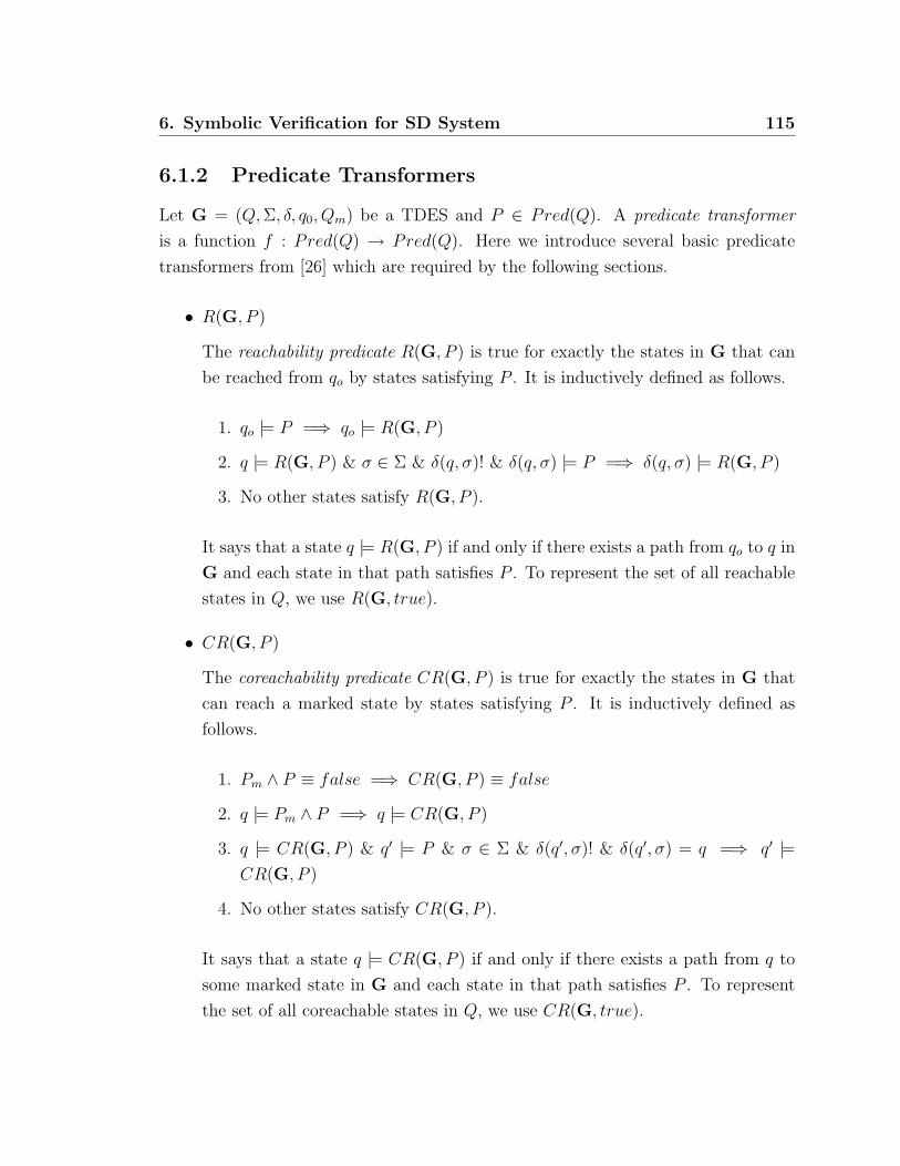
6. Symbolic Verification for SD System 115
6.1.2 Predicate Transformers
Let G = (Q, Σ, δ, q0, Qm) be a TDES and P ∈ Pred(Q). A predicate transformer
is a function f : Pred(Q) → Pred(Q). Here we introduce several basic predicate
transformers from [26] which are required by the following sections.
• R(G, P )
The reachability predicate R(G, P ) is true for exactly the states in G that can
be reached from qo by states satisfying P . It is inductively defined as follows.
1. qo |= P =⇒ qo |= R(G, P )
2. q |= R(G, P ) & σ ∈ Σ & δ(q, σ)! & δ(q, σ) |= P =⇒ δ(q, σ) |= R(G, P )
3. No other states satisfy R(G, P ).
It says that a state q |= R(G, P ) if and only if there exists a path from qo to q in
G and each state in that path satisfies P . To represent the set of all reachable
states in Q, we use R(G, true).
• CR(G, P )
The coreachability predicate CR(G, P ) is true for exactly the states in G that
can reach a marked state by states satisfying P . It is inductively defined as
follows.
1. Pm ∧ P ≡ false =⇒ CR(G, P ) ≡ false
2. q |= Pm ∧ P =⇒ q |= CR(G, P )
3. q |= CR(G, P ) & q′ |= P & σ ∈ Σ & δ(q′, σ)! & δ(q′, σ) = q =⇒ q′ |=CR(G, P )
4. No other states satisfy CR(G, P ).
It says that a state q |= CR(G, P ) if and only if there exists a path from q to
some marked state in G and each state in that path satisfies P . To represent
the set of all coreachable states in Q, we use CR(G, true).

116 6. Symbolic Verification for SD System
• CR(G, P ′, Σ′, P )
Let P ′ ∈ Pred(Q) and Σ′ ⊆ Σ. Once we fix G, P ′ and Σ′, CR(G, P ′, Σ′, P ) is
then a predicate transformer. The predicate CR(G, P ′, Σ′, P ) is true for exactly
the states in G that can reach a state in G satisfying P ′, by states that satisfy
P and by transition with events in Σ′. It is inductively defined as follows.
1. P ′ ∧ P ≡ false =⇒ CR(G, P ′, Σ′, P ) ≡ false
2. q |= P ′ ∧ P =⇒ q |= CR(G, P ′, Σ′, P )
3. q |= CR(G, P ′, Σ′, P ) & q′ |= P & σ ∈ Σ′ & δ(q′, σ)! & δ(q′, σ) = q
=⇒ q′ |= CR(G, P ′, Σ′, P )
4. No other states satisfy CR(G, P ′, Σ′, P ).
By comparing with definition of coreachablity predicate CR, we have
CR(G, Pm, Σ, P ) ≡ CR(G, P )
6.2 Symbolic Representation
For symbolic verification of SD systems, we need to have a representation for states
and transitions. We will use the symbolic representation from Song [26], who in turn
based his work on Ma [14]. In this section, we only introduce the necessary definitions
from this representation that are needed for the computation and verification in the
following sections.
6.2.1 State Subsets
Let G = (Q, Σ, δ, qo, Qm) = G1 ×G2 × ..×Gn be the product TDES of component
TDES Gi where Gi = (Qi, Σi, δi, qo,i, Qm,i) for i = 1, 2, .., n. For any state q ∈ Q, we
have q = (q1, q2, .., qn) where qi ∈ Qi.
In later sections we will be evaluating the meet of component TDES for some of the
verifications. The only difference between the meet and the product of these TDES is
that, the product might contain unreachable states but the meet does not. However,
the checking of unreachable states is expensive and therefore the reachability check is

6. Symbolic Verification for SD System 117
performed over the entire system at the end. In addition, since including unreachable
states does not effect the closed loop behavior, using the product TDES will not
introduce any error.
Definition 6.2.1. For G = G1 ×G2 × .. ×Gn, let i = 1, 2, .., n and qi ∈ Qi. The
state variable vi for the i-th component TDES Gi is a variable of domain Qi. If vi
has assigned value qi, then vi = qi returns T ; otherwise it returns F .
Here we use ‘=’ to if vi has been assigned value qi, because ‘≡’ has been used for
logical equivalence between state predicates.
Definition 6.2.2. For G = G1×G2× ..×Gn, the state variable vector v is a vector
[v1, v2, .., vn] of state variables vi from each component TDES Gi. For state subset
A ⊆ Q, we write predicate
PA(v) :=∨
q∈A(v1 = q1 ∧ v2 = q2 ∧ .. ∧ vn = qn)
or PA if v is understood.
6.2.2 Transitions
Let G = (Q, Σ, δ, qo, Qm) = G1 ×G2 × ..×Gn be the product TDES of component
TDES Gi = (Qi, Σi, δi, qo,i, Qm,i) for i = 1, 2, .., n as defined in previous section.
Definition 6.2.3. For G = G1 ×G2 × .. ×Gn, let σ ∈ Σ. A transition predicate
Nσ : Q×Q → T, F identifies all the transitions for σ in G and is defined as follows.
(∀q, q′ ∈ Q)Nσ(q, q′) :=
T, if δ(q, σ)! & δ(q, σ) = q′
F, otherwise.
To distinguish between source states and destination states, we need to have two
different vectors of state variables, as defined below.
Definition 6.2.4. For G = G1 × G2 × .. × Gn, let i = 1, 2, .., n. For each Gi,
we have the normal state variable vi (source state) and the prime state variable v′i(destination state), both with domain Qi. For G, we have the normal state variable
vector v = [v1, v2, .., vn] and the prime state variable vector v′ = [v′1, v′2, .., v
′n].

118 6. Symbolic Verification for SD System
For each σ ∈ Σ, we can write the transition predicate for σ, Nσ, as below. Essen-
tially, if we set v = q and v′ = q′ such that δ(q, σ) = q′, then Nσ(v,v′) will return
T .
Nσ(v,v′) :=∧
1≤i≤n
(∨
qi,q′i∈Qi|δi(qi,σ)=q′i(vi = qi) ∧ (v′i = q′i)
)
However, when designing a system with multiple component TDES defined over
different event set, such as when we use the synchronous product operator, each
component TDES must be selflooped at each state with events that are not in its
own event set. This of course makes the transition predicate much more complicated.
A new representation to avoid this issue is defined as below. Note that the size of vσ
and v′σ will always be the same.
Definition 6.2.5. We use the transition tuple (vσ,v′σ, Nσ) to represent the transition
on σ, where vσ = vi ∈ v|σ ∈ Σi, v′σ = v′i ∈ v′|σ ∈ Σi and
Nσ(v,v′) :=∧
1≤i≤n|σ∈Σi
( ∨
qi,q′i∈Qi|δi(qi,σ)=q′i(vi = qi) ∧ (v′i = q′i)
)
Although selflooped transitions are not specified in the definition, the selfloop
information is still expressed. For those state variables that are not in vσ, we know
that the corresponding component TDES must be selflooped with event σ on each
state, so we do not need to express this explicitly. Definition 6.2.5 will work fine with
systems where these self-loops have already been added.
Since BDD [8] does not support first order logic by itself, to compute state transi-
tions we will need the following definition taken from the existential quantifier elimi-
nation method for finite domain [1].
Definition 6.2.6. For G = G1 ×G2 × .. ×Gn, let σ ∈ Σ and (vσ,v′σ, Nσ) be the
transition tuple for σ in G. For i = 1, 2, .., n, if vi ∈ vσ and v′i ∈ v′σ, then define
∃viNσ :=∨
qi∈Qi
Nσ[qi/vi] ∃v′iNσ :=∨
qi∈Qi
Nσ[qi/v′i]
where Nσ[qi/vi] is the predicate Nσ with each term vi substituted by qi, and Nσ[qi/v′i]
is defined analogously.

6. Symbolic Verification for SD System 119
We use the above method to eliminate either the normal or prime variable, so
that we can express the statement using propositional logic that we can represent as
a BDD.
Let vσ = v1, v2, .., vm for m > 0. For convenience, we write ∃vσNσ to represent
∃v1(∃v2..(∃vmNσ)..) and the resulting predicate should contain only prime variables
in v′σ. For any computation of state predicates, we need all input variables to be
consistent. That is, either all predicates in the computation have to be expressed
as normal variables or prime variables. We thus need to substitute all the prime
variables by normal variables, denoted as ∃vσNσ[v′σ → vσ]. The substitution should
return the predicate for the set of target states for σ transitions in G. This means
that each state in this set has a σ transition entering it.
Let v′σ = v′1, v′2, .., v′m. For convenience, we also write ∃v′σNσ to represent
∃v′1(∃v′2..(∃v′mNσ)..) and the resulting predicate should contain only normal variables
in vσ, which represents the set of source states for σ transitions in G. This means
that each state in this set has a σ transition leaving it.
6.3 Symbolic Computation
We will now discuss symbolic computation based on the symbolic representation we
just introduced. This work is based on the work of Song [26] who in turn based his
work on Ma [14].
6.3.1 Transitions and Inverse Transitions
Let G = (Q, Σ, δ, qo, Qm) = G1 ×G2 × ..×Gn be a TDES plant. For a state q ∈ Q
and a event σ ∈ Σ, we want to compute the transition δ(q, σ) using the symbolic
representation introduced previously. To do this, for QP ⊆ Q, where P ∈ Pred(Q),
we can compute
Q′P =
⋃q∈Qp
δ(q, σ)
and then find P ′ := pr(Q′P ). However, computing q′ one by one is time consuming
for systems with large statespaces. Instead, we can directly compute the predicate of
the set of next states from the predicate of the set of current states.

120 6. Symbolic Verification for SD System
The computation is based on a function δ : Pred(Q) × Σ → Pred(Q) defined to
be
(∀P ∈ Pred(Q))(∀σ ∈ Σ)δ(P, σ) := pr(q′ ∈ Q|(∃q |= P )δ(q, σ) = q′)
As discussed in previous section, the formula ∃vσNσ[v′σ → vσ] returns a predicate
representing the set of target states q′ ∈ Q|(∃q ∈ Q)δ(q, σ) = q′. We thus have the
following definition.
Definition 6.3.1. Let σ ∈ Σ and (vσ,v′σ, Nσ) be the transition tuple for σ in G. For
P ∈ Pred(Q),
δ(P, σ) := (∃vσ(Nσ ∧ P ))[v′σ → vσ]
By first computing Nσ ∧ P in the above definition, we are restricting the source
states to those satisfying P .
We also need an inverse function δ−1 : Pred(Q)× Σ → Pred(Q) to compute the
predicate of the set of source states from the predicate representing the set of target
states, where δ−1 is defined to be
(∀P ∈ Pred(Q))(∀σ ∈ Σ)δ−1(P, σ) := pr(q ∈ Q|δ(q, σ) |= P)
Since the formula ∃v′σNσ returns a predicate representing the set of source states
q ∈ Q|δ(q, σ)!, we have the following definition.
Definition 6.3.2. Let σ ∈ Σ and (vσ,v′σ, Nσ) be the transition tuple for σ in G. For
P ∈ Pred(Q),
δ−1(P, σ) := ∃v′σ(Nσ ∧ (P [vσ → v′σ]))
In the definition, P [vσ → v′σ] returns predicate P with its normal variables sub-
stituted by prime variables. As prime variables represent target states, this has the
effect of restricting the target states to those satisfying P .

6. Symbolic Verification for SD System 121
6.3.2 Computation of Predicate Transformers
Let G = (Q, Σ, δ, qo, Qm) = G1 × G2 × .. × Gn be the cross product TDES of
component TDES Gi for i = 1, 2, .., n. Let P ∈ Pred(Q). To compute the predicate
transformers R and CR introduced in Section 6.1.2, we have the following algorithms
which are taken from [26].
Reachability Check
Algorithm 6.1 R(G, P )
1: P1 ← P ∧ pr(qo)2: repeat
3: P2 ← P1
4: for i ← 1 to n do
5: repeat
6: P3 ← P1
7: P1 ← P1 ∨( ∨
σ∈Σi
(δ(P1, σ) ∧ P )
)
8: until P1 ≡ P3
9: end for
10: until P1 ≡ P2
11: return P1
In Algorithm 6.1, procedure R(G, P ) takes a TDES G and a predicate P , then
returns a predicate which holds a set of states in G that can be reached from qo by
states satisfying P .
At line 1, P1 is initialized to be the predicate which represents the initial state
qo or ∅ if qo 6|= P .
From line 2 to line 10, for i ∈ 1, .., n, we loop over σ ∈ Σi and determine states
that satisfy P , and are reachable from a state that satisfies P1 by a σ transition.
Due to the intermediate logic formula expansion problem described in [26], that
intermediate logic formula can become large and complicated even though the final
predicate might be relatively small, the for loop on line 4 to line 9 repeatedly
modifies P1 on a component TDES basis. We start with a specific TDES, Gi, and
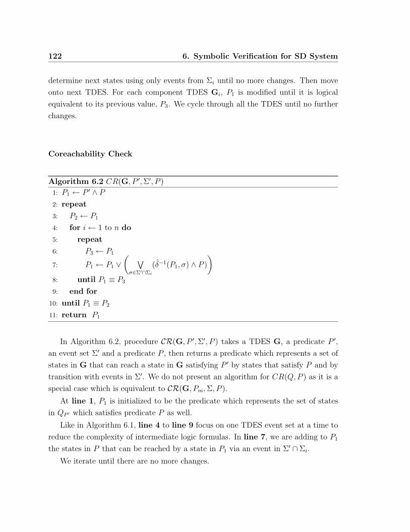
122 6. Symbolic Verification for SD System
determine next states using only events from Σi until no more changes. Then move
onto next TDES. For each component TDES Gi, P1 is modified until it is logical
equivalent to its previous value, P3. We cycle through all the TDES until no further
changes.
Coreachability Check
Algorithm 6.2 CR(G, P ′, Σ′, P )
1: P1 ← P ′ ∧ P
2: repeat
3: P2 ← P1
4: for i ← 1 to n do
5: repeat
6: P3 ← P1
7: P1 ← P1 ∨( ∨
σ∈Σ′∩Σi
(δ−1(P1, σ) ∧ P )
)
8: until P1 ≡ P3
9: end for
10: until P1 ≡ P2
11: return P1
In Algorithm 6.2, procedure CR(G, P ′, Σ′, P ) takes a TDES G, a predicate P ′,
an event set Σ′ and a predicate P , then returns a predicate which represents a set of
states in G that can reach a state in G satisfying P ′ by states that satisfy P and by
transition with events in Σ′. We do not present an algorithm for CR(Q,P ) as it is a
special case which is equivalent to CR(G, Pm, Σ, P ).
At line 1, P1 is initialized to be the predicate which represents the set of states
in QP ′ which satisfies predicate P as well.
Like in Algorithm 6.1, line 4 to line 9 focus on one TDES event set at a time to
reduce the complexity of intermediate logic formulas. In line 7, we are adding to P1
the states in P that can be reached by a state in P1 via an event in Σ′ ∩ Σi.
We iterate until there are no more changes.

6. Symbolic Verification for SD System 123
6.4 Symbolic Verification
The TDES systems we are interested in are composed of a plant G and a supervisor
S, with system event set Σ.
Given G′i = (Yi, Σi, δi, yo,i, Ym,i) and G′ = G′
1||G′2||..||G′
n, for i = 1, 2, .., n, let
Gi = selfloop(G′i, Σ− Σi). The plant is defined as:
G = G1 ×G2 × ..×Gn := (Y, Σ, δ, yo, Ym)
Given Si = (Xi, Σ, ξi, xo,i, Xm,i), the supervisor is defined as
S = S1 × S2 × ..× Sm := (X, Σ, ξ, xo, Xm)
Therefore both G and S are defined over the global event set Σ. If our com-
ponent supervisors were defined over subsets of Σ and combined together using the
synchronous product, we would add selfloops of the missing events as we did for the
plant components, and then use these new DES from then on.
The closed-loop system, Gcl, is the product of the plant and supervisor
Gcl = G× S := (Q, Σ, η, qo, Qm)
where Q = Y ×X = Y1 × Y2 × ..× Yn ×X1 ×X2 × ..×Xm, Σ = Σc∪Σu, η = δ × ξ,
qo = (yo, xo) and Qm = Ym ×Xm. See Definition 2.2.11 for more details.
Note that we cannot use Gcl = meet(G,S) as meet by definition only contains
reachable states, which is too restrictive. The product DES is the same as meet, but
it can include unreachable states.
Definition 6.4.1. Let Gcl = G×S := (Q, Σ, η, qo, Qm) where G = G1×G2×..×Gn =
(Y, Σ, δ, yo, Ym) and S = S1×S2×..×Sm = (X, Σ, ξ, xo, Xm). For a given event σ ∈ Σ,
the σ plant transition predicate NG,σ : Q×Q → T, F can be written as
NG,σ(v,v′) :=∧
1≤i≤n
( ∨
yi,y′i∈Yi|δi(yi,σ)=y′i(vi = yi) ∧ (v′i = y′i)
)
and the σ supervisor transition predicate NS,σ : Q×Q → T, F can be written as
NS,σ(v,v′) :=∧
1≤i≤m
( ∨
xi,x′i∈Xi|ξi(xi,σ)=x′i(vi+n = xi) ∧ (v′i+n = x′i)
)

124 6. Symbolic Verification for SD System
NG,σ and NS,σ are state predicates defined on Q×Q and use the v and v′ variables
like Nσ. We use NG,σ when we wish to determine if there is a σ defined at the plant
portion of the indicated states, say for when we are checking controllability. Similarly,
we use NS,σ when we wish to determine if there is a σ defined at the supervisor portion
of the indicated states. They must be defined over Q× Q so the results of each can
be compared and combined with other state predicates on Q.
Definition 6.4.2. Let σ ∈ Σ and NG,σ be the σ transition predicate for plant G =
(Y, Σ, δ, yo, Ym). We define δG : Pred(Q)× Σ → Pred(Q), for P ∈ Pred(Q), to be
δG(P, σ) := (∃v(NG,σ ∧ P ))[v′ → v]
and we also define δ−1G : Pred(Q)× Σ → Pred(Q) to be
δ−1G (P, σ) := ∃v′(NG,σ ∧ (P [v → v′]))
Definition 6.4.3. Let σ ∈ Σ and NS,σ be the σ transition predicate for supervisor
S = (X, Σ, ξ, xo, Xm). We define ξ : Pred(Q) × Σ → Pred(Q), for P ∈ Pred(Q), to
be
ξ(P, σ) := (∃v(NS,σ ∧ P ))[v′ → v]
and we also define ξ−1 : Pred(Q)× Σ → Pred(Q) to be
ξ−1(P, σ) := ∃v′(NS,σ ∧ (P [v → v′]))
6.4.1 Untimed Controllability
To verify that a supervisor S = (X, Σ, ξ, xo, Xm) is controllable with respect to plant
G = (Y, Σ, δ, yo, Ym), we need the closed loop system Gcl = (Q, Σ, η, qo, Qm) as defined
in Section 6.4. For q ∈ Q, there must exist a state x ∈ X and y ∈ Y such that
q = (y, x).
According to Definition 2.2.15 for untimed controllability, we can express the states
that could cause S to be uncontrollable for G (if they are reachable), as follows:
Definition 6.4.4. Let S = (X, Σ, ξ, xo, Xm) be a supervisor. Let G = (Y, Σ, δ, yo, Ym)
be a plant, then
Qbad = q = (y, x) ∈ Q|(∃σu ∈ Σu)δ(y, σu)! & ξ(x, σu) 6 !
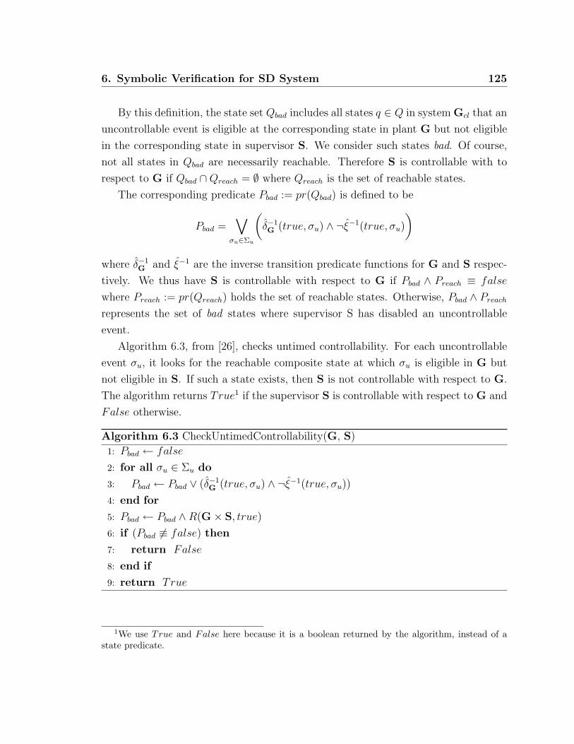
6. Symbolic Verification for SD System 125
By this definition, the state set Qbad includes all states q ∈ Q in system Gcl that an
uncontrollable event is eligible at the corresponding state in plant G but not eligible
in the corresponding state in supervisor S. We consider such states bad. Of course,
not all states in Qbad are necessarily reachable. Therefore S is controllable with to
respect to G if Qbad ∩Qreach = ∅ where Qreach is the set of reachable states.
The corresponding predicate Pbad := pr(Qbad) is defined to be
Pbad =∨
σu∈Σu
(δ−1G (true, σu) ∧ ¬ξ−1(true, σu)
)
where δ−1G and ξ−1 are the inverse transition predicate functions for G and S respec-
tively. We thus have S is controllable with respect to G if Pbad ∧ Preach ≡ false
where Preach := pr(Qreach) holds the set of reachable states. Otherwise, Pbad ∧ Preach
represents the set of bad states where supervisor S has disabled an uncontrollable
event.
Algorithm 6.3, from [26], checks untimed controllability. For each uncontrollable
event σu, it looks for the reachable composite state at which σu is eligible in G but
not eligible in S. If such a state exists, then S is not controllable with respect to G.
The algorithm returns True1 if the supervisor S is controllable with respect to G and
False otherwise.
Algorithm 6.3 CheckUntimedControllability(G, S)
1: Pbad ← false
2: for all σu ∈ Σu do
3: Pbad ← Pbad ∨ (δ−1G (true, σu) ∧ ¬ξ−1(true, σu))
4: end for
5: Pbad ← Pbad ∧R(G× S, true)
6: if (Pbad 6≡ false) then
7: return False
8: end if
9: return True
1We use True and False here because it is a boolean returned by the algorithm, instead of astate predicate.
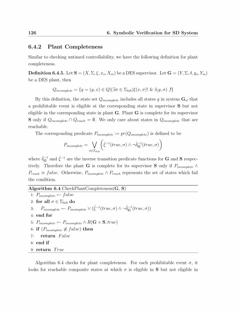
126 6. Symbolic Verification for SD System
6.4.2 Plant Completeness
Similar to checking untimed controllability, we have the following definition for plant
completeness.
Definition 6.4.5. Let S = (X, Σ, ξ, xo, Xm) be a DES supervisor. Let G = (Y, Σ, δ, yo, Ym)
be a DES plant, then
Qincomplete = q = (y, x) ∈ Q|(∃σ ∈ Σhib)ξ(x, σ)! & δ(y, σ) 6 !By this definition, the state set Qincomplete includes all states q in system Gcl that
a prohibitable event is eligible at the corresponding state in supervisor S but not
eligible in the corresponding state in plant G. Plant G is complete for its supervisor
S only if Qincomplete ∩ Qreach = ∅. We only care about states in Qincomplete that are
reachable.
The corresponding predicate Pincomplete := pr(Qincomplete) is defined to be
Pincomplete =∨
σ∈Σhib
(ξ−1(true, σ) ∧ ¬δ−1
G (true, σ)
)
where δ−1G and ξ−1 are the inverse transition predicate functions for G and S respec-
tively. Therefore the plant G is complete for its supervisor S only if Pincomplete ∧Preach ≡ false. Otherwise, Pincomplete ∧ Preach represents the set of states which fail
the condition.
Algorithm 6.4 CheckPlantCompleteness(G, S)
1: Pincomplete ← false
2: for all σ ∈ Σhib do
3: Pincomplete ← Pincomplete ∨ (ξ−1(true, σ) ∧ ¬δ−1G (true, σ))
4: end for
5: Pincomplete ← Pincomplete ∧R(G× S, true)
6: if (Pincomplete 6≡ false) then
7: return False
8: end if
9: return True
Algorithm 6.4 checks for plant completeness. For each prohibitable event σ, it
looks for reachable composite states at which σ is eligible in S but not eligible in

6. Symbolic Verification for SD System 127
G. If such a state exists, then plant G fails to be complete for supervisor S and the
algorithm returns False. Otherwise it returns True.
6.4.3 Non-blocking
Algorithm 6.5 checks for non-blocking as defined in Definition 2.2.6. It compares the
set of reachable states with the set of coreachable states, then returns True if there
is no reachable state that is not coreachable and False otherwise.
Algorithm 6.5 Nonblocking(G)
1: Preach ← R(G, true)
2: Pcoreach ← CR(G, Preach)
3: if (Preach ∧ ¬Pcoreach 6≡ false) then
4: return False
5: end if
6: return True
6.4.4 Activity Loop Free
By Definition 2.3.3 of Activity Loop Free (ALF), we require that for each reachable
state in a TDES there will not be a non-empty string of activity events leaving from
that state and back to itself. This is to prevent the TDES from “stopping the clock”.
Algorithm 6.6 checks the given TDES G and returns True if it is ALF and False
otherwise.
At line 1, Algorithm 6.6 first calculates all the reachable states. Then for each
state q in Pchk, it starts from any states Pvisit reached via activity events from q at
line 4. From there, in the following loop from line 7 to line 17 it traverses to next
states Pnext until no more state can be reached by activity events.
At each iteration of the loop, the algorithm first checks if there is an overlap
between Pvisit and Pnext. Then it checks if state q has been reached again. If state q
has been reached again, then the system is not ALF. Otherwise, the loop continues.
Once the check is done for state q, this state is removed from Pchk. If there is no
overlap found in the loop, all the visited states are removed from Pchk. After that,

128 6. Symbolic Verification for SD System
Algorithm 6.6 ALF(G)
1: Pchk ← R(G, true)
2: Ptmp ← false
3: for (q |= Pchk) do
4: Pvisit ←( ∨
σ∈Σact
δ(pr(q), σ)
)∧Pchk
5: overlap ← False
6: Pnext ← Pvisit
7: repeat
8: Pnext ←( ∨
σ∈Σact
δ(Pnext, σ)
)∧Pchk
9: Ptmp ← Pvisit
10: if (Pvisit ∧ Pnext 6≡ false) then
11: overlap ← True
12: end if
13: Pvisit ← Pvisit ∨ Pnext
14: if (q |= Pvisit) then
15: return False
16: end if
17: until (Pvisit ≡ Ptmp)
18: Pchk ← Pchk − pr(q)19: if (¬overlap) then
20: Pchk ← Pchk − Pvisit
21: end if
22: end for
23: return True
the algorithm moves to next state in Pchk. If there was no False returned during the
loop, the algorithm will consider it to be ALF and returns True.
6.4.5 Proper Time Behavior
By Definition 2.3.5 for Proper Time Behavior, we require that at each reachable state
in a TDES plant, either an uncontrollable event or a tick event is eligible. Algorithm

6. Symbolic Verification for SD System 129
6.7 checks the given TDES plant G and returns True if it has a proper time behavior
and False otherwise.
Algorithm 6.7 ProperTimeBehavior(G)
1: P1 ←∨
σ∈Σu∪τδ−1(true, σ)
2: P2 ← R(G, true)
3: if P2 − P1 6≡ false then
4: return False
5: end if
6: return True
Algorithm 6.7 first calculates P1, the set of all states that have a Σu∪τ transition
leaving it. It then compares P1 to the set P2 of reachable states. When there is a
state in P2 but not in P1, it implies that the state is reachable and neither a tick or
an uncontrollable event is eligible at this state.
6.4.6 SD Controllability and S-Singular Prohibitable Behav-
ior
Algorithm 6.8 evaluates SD controllability for supervisor S = (X, Σ, ξ, xo, Xm) with
respect to plant G = (Y, Σ, δ, yo, Ym), where G, S, and the closed loop system, Gcl =
G×S are as defined in Section 6.4. In addition, the algorithm’s subroutine, Algorithm
6.11, also checks that G has S-singular prohibitable behavior. As checking Point i
of the SD controllability definition is the same as checking untimed controllability
(Algorithm 6.3), we will not mention it explicitly here.
Σ is defined to be Σ = Σhib∪Σu∪τ, where Σhib is the set of prohibitable events
in G and Σu is the set of uncontrollable events in G. The set of controllable events
is Σc = Σhib ∪ τ, and the set of activity events is Σact = Σhib∪Σu.
The algorithm makes the following assumptions:
• The set Σhib of prohibitable events equals the set Σfor of forcible events
• The plant has proper time behavior (checked by Algorithm 6.7)
• All TDES are finite and deterministic

130 6. Symbolic Verification for SD System
• The closed loop system, Gcl, is activity loop free (ALF) (checked by Algorithm
6.6)
The algorithm uses certain variables as it executes.
Preach: The predicate of the set of reachable states of Gcl.
PSF : The predicate of the set that contains sampling states of Gcl found
by the algorithm.
ZSP : This set contains the predicates of sampling states in Gcl found and
not yet analyzed by the algorithm.
NG,σ, NS,σ: Transition predicates for σ for G and S as in Definition 6.4.1.
Nσ: Transition predicate for σ for Gcl as in Definition 6.2.5.
δ: Transition function for state predicates for Gcl as in Definition 6.3.1.
δG: Transition function for state predicates for G only as in Definition
6.4.2.
ξ: Transition function for state predicates for S only as in Definition
6.4.3.
pNerFail: This set pNerFail ⊆ Pwr(Pred(Q)) is a set of sets of predicates
that stores information where Point iii.2 in Definition 3.2.2 of SD
controllability may have failed.
SDControllable: This flag asserts if S is SD controllable with respect to G.
Algorithm 6.8 starts at the initial state, which is always a sampling state. Then it
analyzes the concurrent behavior of this state by creating a reachability tree with the
initial state as a node. It expands the tree until all paths terminate at a tick event.
Since we first check that the closed loop system is activity loop free, the system
has a finite state space and that the plant has proper time behavior, we are either
guaranteed that we will reach a tick after a finite number of events, or the system
will fail Point ii of the SD controllability definition. Any new sampling states found
are then analyzed as above, until all reachable sampling states have been analyzed.
As the reachability tree for a given sampling period is created, conformance to
Definition 3.2.2 of SD controllability is tested. We also test here that G has S-singular

6. Symbolic Verification for SD System 131
Algorithm 6.8 CheckSDControllability(G,S)
1: Gcl ← G× S
2: Preach ← R(G× S, true)
3: if (CheckSDContii(G,S, Preach) = False) then
4: return False
5: end if
6: SDControllable ← True
7: PSF ← prz08: ZSP ← prz09: pNerFail ← ∅
10: while (ZSP 6= ∅) do
11: Pss ←Pop(ZSP )
12: SDControllable ←AnalyseSampledState(G,S, PSF , ZSP , Preach, Pss, pNerFail)
13: if (¬SDControllable) then
14: return False
15: end if
16: end while
17: if (pNerFail 6= ∅) then
18: SDControllable ← RecheckNerodeCells(pNerFail)
19: if (¬SDControllable) then
20: return False
21: end if
22: end if
23: if (¬ CheckSamplingMarkingStates(Preach)) then
24: return False
25: end if
26: return True
prohibitable behavior. With the exception of Point iii.2, evaluation stops if the test
for any of the other points fail. If the test for Point iii.2 fails, the problem area
is noted and the algorithm continues until all reachable sampling states have been
analyzed. Nerode cells will be rechecked and then Point iii.2 is tested again.

132 6. Symbolic Verification for SD System
In the algorithm, pNerFail represents states reached by concurrent strings with
the same occurrence image, thus should belong to the same equivalence classes for
≡L(S)∩L(G) and ≡Lm(S)∩Lm(G). It contains the states these strings ended up in, and
we will now check to see if these states actually represent the same equivalence cells.
i.e. they are equivalent mod λ (Definition 2.2.7).
Finally, the algorithm checks Point iv in Definition 3.2.2 of SD controllability by
comparing the set of marked states, implied by Pm, with the set of states reached by
a tick event. If not all states implied by Pm are reached by a tick and if that state
not reached by a tick is not the initial state zo, then it returns False.
If all tests pass, the algorithm returns True at the end.
See following sections for subroutines in Algorithm 6.8. The subroutine CheckS-
DContii is defined in Algorithm 6.9. The subroutine AnalyseSampledState is defined
in Algorithm 6.10. The subroutine RecheckNerodeCells is defined in Algorithm 6.13.
The subroutine CheckSamplingMarkingStates is defined in Algorithm 6.15.
Point ii of SD Controllability
Algorithm 6.9 checks Point ii of the SD Controllability definition. The algorithm
takes the following three parameters: a plant G, a supervisor S and a predicate Preach
of all reachable states in Gcl.
Algorithm 6.9 CheckSDContii(G,S, Preach)
1: Pq−hib ←∨
σ∈Σhib
∃v′Nσ
2: Pbad ← ∃v′Ntick ∧ Pq−hib
3: if Pbad ∧ Preach 6≡ false then
4: return False
5: end if
6: Pbad ← ∃v′NG,tick ∧ ¬(∃v′NS,tick) ∧ ¬Pq−hib
7: if Pbad ∧ Preach 6≡ false then
8: return False
9: end if
10: return True
From line 1 to line 5 the algorithm checks the “⇒” part of Point ii. It checks

6. Symbolic Verification for SD System 133
for any reachable states in Gcl that has both a prohibitable event and tick event
enabled. If such a state exists, then it returns False.
Then from line 6 to line 9, the algorithm checks “⇐” part of Point ii. It checks
to see if a reachable state exists in Gcl where no prohibitable events are eligible, but
a tick is eligible in G but not in S. If such a state exists, then it returns False.
AnalyzeSampledState
Algorithm 6.10 analyzes the concurrent behavior for sampling state qss, represented
by predicate Pss. The algorithm takes seven parameters. See Algorithm 6.8 for their
definitions.
During the execution, the algorithm uses the following variables:
ΣElig: The set of prohibitable events eligible in both G and S at qss, the sampling
state in Gcl that we are processing.
Pq: The predicate of current state in Gcl.
Σposs: The set of events eligible in both G and S at predicate Pq of current state in
Gcl.
ΣGposs: The set of prohibitable events eligible in G at predicate Pq of current state in
Gcl.
nextLabel: This number represents the next unused node in Bmap. It is used to name newly
discovered nodes of the reachability tree.
Bmap: This partial function Bmap : N → Pred(Q) maps the nodes of the reachability
tree to the predicates of the states of Gcl which the nodes represent. This
function will sometimes be treated like the set Bmap ⊆ N × Pred(Q). Note,
N = 0, 1, 2, . . . is the set of natural numbers.
Bp: This is the set of nodes pending to be expanded in the reachability tree.
Bconc: The set Bconc ⊆ N ×Pred(Q) contains nodes that represent concurrent strings
and the sampled states the strings lead to. For (b, q) ∈ Bconc, the node b is a
node at which tick is eligible in G and S, and q is the sampling state of Gcl
that the tick leads to.

134 6. Symbolic Verification for SD System
Algorithm 6.10 AnalyseSampledState(G,S, PSF , ZSP , Preach, Pss, pNerFail)
1: Bmap ← (0, Pss)2: Bconc ← ∅3: Bp ← 04: nextLabel ← 1
5: OccuB ← (0, ∅)6: while Bp 6= ∅ do
7: b ←Pop(Bp)
8: Pq ← Bmap(b)
9: Σposs ← ∅10: ΣGposs ← ∅11: for all σ ∈ Σ do
12: if (δ(Pq, σ) 6≡ false) then
13: Σposs ← Σposs ∪ σ14: end if
15: if (δG(Pq, σ) 6≡ false) then
16: ΣGposs ← ΣGposs ∪ (σ ∩ Σhib)
17: end if
18: end for
19: if (Pq ≡ Pss) then
20: ΣElig ← Σposs ∩ Σhib
21: end if
22: if ((Σposs ∪OccuB(b)) ∩ Σhib 6= ΣElig) then
23: return False
24: end if
25: if (¬NextState(b, Σposs, ΣGposs, Pq, nextLabel, Bmap, Bp, Bconc, PSF , ZSP , OccuB(b)))
then
26: return False
27: end if
28: end while
29: CheckNerodeCells(Bconc, OccuB, pNerFail)
30: return True

6. Symbolic Verification for SD System 135
OccuB: The partial function OccuB : N → Pwr(Σ) maps the nodes of the reachability
tree to the occurrence image of the string that they represent. This function
will sometimes be treated like the set OccuB ⊆ N × Pwr(Σ).
The algorithm builds the reachability tree, starting at qss, until all nodes termi-
nates at a tick event or one of our checks fail. As we need to evaluate the strings
taking us from the sampled state, we need to know how we got to a given state. So we
introduce nodes for the states we reach, and associate with the node the occurrence
image of the string that brought us to that node. We use map OccuB to do this. The
function Bmap maps the nodes back to the states in Gcl that they represent. The
information is stored per node, not per state of Gcl. It means there could be two or
more nodes that corresponds to the same state, but have possibly different occurrence
images, as they were reached by different strings.
When the algorithm starts, we store the set of prohibitable events that are eligible
at our starting sampling state. Point iii.1 in Definition 3.2.2 for SD controllability is
analyzed as the tree is built. In the algorithm, a concurrent string is represented by
the label b of the node it is associated with, and a sampled string is represented by
the sampling state qss. From line 22 to line 24, the algorithm checks this condition.
If the test fails, the algorithm returns False.
After the reachability tree is complete, Bconc will represent the concurrent strings
leaving the sampling state implied by predicate Pss, and the sampling state each
string leads to. We then call CheckNerodeCells which will indicate via pNerFail
what further checks are needed. This is how Point iii.2 is checked.
In next section we will discuss subroutine NextState (Algorithm 6.11) and sub-
routine CheckNerodeCells (Algorithm 6.12), as both algorithms are called from Anal-
yseSampledState.
NextState
Algorithm 6.11 determines the next states to be processed for Algorithm 6.10. Subrou-
tine NextState takes parameters b, Σposs, ΣGposs, Pq, nextLabel, Bmap, Bp, Bconc, PSF , ZSP ,
and OccuB(b). See Algorithms 6.8 and 6.10 for their definitions.
The algorithm returns if the set of eligible events, Σposs, at state q (implied by
Pq) of Gcl, is empty. If tick is possible at state q, we determine the new sampling

136 6. Symbolic Verification for SD System
Algorithm 6.11 NextState(. . .)
1: if (Σposs = ∅) then
2: return True
3: end if
4: if (τ ∈ Σposs) then
5: Pq′ ← δ(Pq, tick)
6: Push(Bconc, (b, Pq′))
7: if (Pq′ ∧ PSF ≡ false) then
8: PSF ← PSF ∨ Pq′
9: Push(ZSP , Pq′)
10: end if
11: end if
12: for all σ ∈ ΣGposs do
13: if (OccuB(b) ∩ σ 6= ∅) then
14: return False
15: end if
16: end for
17: for all σ ∈ (Σposs − τ) do
18: Pq′ ← δ(Pq, σ)
19: b′ ← nextLabel
20: nextLabel ← nextLabel + 1
21: Push(Bmap, (b′, Pq′))
22: Push(Bp, b′)
23: Push(OccuB, (b′, OccuB(b) ∪ σ))24: end for
25: return True
state that tick takes us to, and then add b and the state to Bconc. If we have not yet
encountered this state, it is added to PSF and ZSP .
In lines 12 to 16, we check that no prohibitable event is currently eligible in G
if it has already occurred this sampling period. This is part of checking if G has
S-singular prohibitable behavior.
Then for each non-tick event σ, it finds the next state implied by Pq′ , assigns a

6. Symbolic Verification for SD System 137
new node b′ to it and pushes (b′, q′) onto Bmap, and b′ onto the set of pending nodes,
Bp. It also associates the occurrence image of the strings that took us to b′ with node
b′, via OccuB.
CheckNerodeCells
Algorithm 6.12 is used to determine if we have possible violations of Point iii.2 of the
SD controllability definition. Subroutine CheckNerodeCells is passed a set of sampled
states reached in the recent search, plus information on the occurrence images of the
concurrent strings that took us to that state. For more details on these parameters,
see Algorithm 6.10.
Point iii.2 of the SD Controllability definition requires that if two concurrent
strings have the same occurrence image, they must take us to states representing the
same equivalence cell of ≡L(S)∩L(G) and ≡Lm(S)∩Lm(G). In other words, to states that
are λ-equivalent (see Definition 2.2.7). If Gcl is minimal, they must go to the same
state . If they do not, we add each set of non-equal states, represented by variable
Zeqv ⊆ Pred(Q), to pNerFail, and we will later check to see if they are indeed
λ-equivalent. Note that every state predicate in Zeqv represents a single state.
RecheckNerodeCells
Algorithm 6.13 checks state subsets of Gcl stored in pNerFail to see if the states
in a given subset actually are equivalent mod λ (see Definition 2.2.7) to each other.
Subroutine RecheckNerodeCells is passed parameter pNerFail. See Algorithm 6.8 for
the definition of pNerFail.
At a given sampling state, if we found two or more concurrent strings that had the
same occurrence image but terminated in different states, we stored the predicates
that identified the states these strings led us to, in pNerFail. Variable pNerFail
contains all such sets found by Algorithm 6.8 as it processed all the reachable sampling
states of Gcl. For the system to pass Point iii.2 of Definition 3.2.2, the states in a
given state predicate in pNerFail must all be λ-equivalent to each other. If a single
set fails this test, the system fails Point iii.2 of Definition 3.2.2.
From line 1 to line 3, the algorithm first sees if there is actually any state sets
in pNerFail to be checked. If it is empty, it returns True.

138 6. Symbolic Verification for SD System
Algorithm 6.12 CheckNerodeCells(Bconc, OccuB, pNerFail)
1: while (Bconc 6= ∅) do
2: (b, Pq) ←Pop(Bconc)
3: Zeqv ← ∅4: Push(Zeqv, Pq)
5: sameCell ← True
6: for all (b′, Pq′) ∈ Bconc do
7: if (OccuB(b) = OccuB(b′)) then
8: Push(Zeqv, Pq′)
9: Bconc ← Bconc − (b′, Pq′)10: if (Pq 6≡ Pq′) then
11: sameCell ← False
12: end if
13: end if
14: end for
15: if (¬sameCell) then
16: Push(pNerFail, Zeqv)
17: end if
18: end while
19: return
At line 4, variable V isited ⊆ Pred(Q)× Pred(Q) is initialized to the empty set.
After each call to RecheckNerodeCell (Algorithm 6.14) that returns True, V isited
will contain tuples of state predicates, where each predicate in the tuple represents
a single state in Q. Essentially, a tuple belonging to V isited means that Recheck-
NerodeCell has determined that those two states are λ-equivalent. We pass it back
into RecheckNerodeCell so that this information can be reused in future checks.
During the while loop from lines 5 to line 10, we call RecheckNerodeCell for
each element Zeqv ⊆ Pred(Q) in pNerFail. If RecheckNerodeCell returns False, then
the system fails Point iii.2 of Definition 3.2.2.

6. Symbolic Verification for SD System 139
Algorithm 6.13 RecheckNerodeCells(pNerFail)
1: if (pNerFail = ∅) then
2: return True
3: end if
4: V isited ← ∅5: while pNerFail 6= ∅ do
6: Zeqv ←Pop(pNerFail)
7: if ¬ RecheckNerodeCell(Zeqv, V isited) then
8: return False
9: end if
10: end while
11: return True
RecheckNerodeCell
For each set of state predicates Zeqv ⊆ Pred(Q) that Algorithm 6.14 is called with,
we will check that these states identified by the predicates are λ-equivalent to each
other, and return False if they are not. When Subroutine RecheckNerodeCell is
called, parameter V isited ⊆ Pred(Q) × Pred(Q) represents tuples of states that
are known to be λ-equivalent. See Algorithm 6.13 for further details about these
parameters.
At line 1, a state predicate is popped out of Zeqv and labeled as Pq1 .
From line 2 to line 6, the algorithm populates the Pending set with all pairs of
Pq1 and Pq2 , where Pq2 is also popped from Zeqv. Note that state predicates Pq1 and
Pq2 each represent a single state in Q. Set Pending represents all the state pairs that
we wish to show to be λ-equivalent. Of course, we will likely finding new state pairs
that we will also need to test, as our algorithm progresses.
Two states q1, q2 ∈ Q are λ-equivalent if they have the same future with respect
to the marked and closed behavior of Gcl. That means that both states are either
marked, or neither is marked (lines 10-12). It also means that for each σ ∈ Σ (lines
13-28), there is a σ transition at one state if and only if there is a σ transition at the
other (line 17-18). Also, if there is a σ transition leaving each state, the two new
states reached must be λ-equivalent. Obviously if q1 = q2 (line 19), then the two

140 6. Symbolic Verification for SD System
Algorithm 6.14 RecheckNerodeCell(Zeqv, V isited)
1: Pq1 ← Pop(Zeqv)
2: Pending ← ∅3: while Zeqv 6= ∅ do
4: Pq2 ← Pop(Zeqv)
5: Push(Pending, (Pq1 , Pq2))
6: end while
7: while Pending 6= ∅ do
8: (Pq1 , Pq2) ← Pop(Pending)
9: P ← Pq1 ∨ Pq2
10: if (P ∧ Pm 6≡ false) & (P ∧ Pm 6≡ P ) then
11: return False
12: end if
13: for all σ ∈ Σ do
14: P ′ ← δ(P, σ)
15: P ′q1← δ(Pq1 , σ)
16: P ′q2← δ(Pq2 , σ)
17: if (P ′ 6≡ false) then
18: if (P ′q1∧ P ′ 6≡ false) & (P ′
q2∧ P ′ 6≡ false) then
19: if (P ′q16≡ P ′
q2) & ((P ′
q1, P ′
q2) /∈ V isited) then
20: Push(V isited, (P ′q1
, P ′q2
))
21: Push(V isited, (P ′q2
, P ′q1
))
22: Push(Pending, (P ′q1
, P ′q2
))
23: end if
24: else
25: return False
26: end if
27: end if
28: end for
29: end while
30: return True

6. Symbolic Verification for SD System 141
states are λ-equivalent.
Our approach to prove that q1, q2 ∈ Q are λ-equivalent will be to attempt to prove
they are not. We will check the per state conditions (lines 10-12 and lines 17-27),
and then if the states take us to two different states for a common σ transition (line
19), we check to see if the new states already have a tuple in V isited (line 19). If
they do, either they are known to be equivalent or we have already processed the pair
and added their requirements to Pending. If they do not, we add the pair to Pending
and V isited (lines 20-22). This ensures that a state pair is added to pending at
most once, so we will terminate after a finite number of iterations as Gcl has a finite
statespace. There is no sense in adding the pair to Pending twice as processing the
pair twice would not provide new information to check.
The idea is that if the state pair are not equivalent, then we must eventually
reach a state pair that we need to be equivalent, but the states do not have the
same marking information and/or the same possible outgoing event transitions. If we
never reach such a pair (and we have a finite number of possible state pairs to check),
then the original state pairs must be equivalent. Not only that, then every state pair
that we encountered to check, must also be equivalent to each other, or they would
have caused the test to fail. This is why all state pairs in V isited are known to be
equivalent if the algorithm returns true.
As we expect that our plant and supervisor TDES components are typically min-
imal or close to it, we also expect that Gcl is likely minimal or close to it. As such,
we believe that when we start to check that a state pair is equivalent, we expect to
either quickly find out it is not, or have the test terminate successfully as the new
state pairs we encounter to test are actually the same state.
We now make a few additional comments to clarify a few steps of the algorithm.
For lines 14-16, predicate P ′ represents states reached via σ from either state q1 or
state q2, while P ′q1
and P ′q1
represents states reached via σ only from the indicated
state. The condition on line 17 will be satisfied if either state q1 or state q2 has a σ
transition leaving that state. The condition on line 18 will fail if only one of the two
states has a σ transition leaving that state.

142 6. Symbolic Verification for SD System
Checking Point iv of SD Controllability
Point iv in Definition 3.2.2 for SD Controllability is checked by Algorithm 6.15.
Subroutine CheckSamplingMarkingStates is passed the state predicate Preach, which
represents the set of reachable states of Gcl, when it is called by Algorithm 6.8.
Point iv of SD Controllability states that only sampled strings can be marked
strings. This implies that every reachable marked state of Gcl can only have at most
incoming tick transitions from other reachable states.
Algorithm 6.15 CheckSamplingMarkingStates(Preach)
1: P ← ∨σ∈Σ−τ
δ(Preach, σ)
2: if P ∧ Pm 6≡ false then
3: return False
4: end if
5: return True
At line 1, we first identify all states with an incoming non-tick transition from a
reachable state. This implies that all of these states are also reachable. At line 2,
we check to see if any of these states are also marked. If one of them is marked, then
Gcl fails this condition and we return False.

Chapter 7
Examples
In this chapter we provide illustrative examples for key required conditions we have
defined for an SD system (see Section 7.1), as well as a successful example based
on Hill’s Flexible Manufacturing System (FMS) from [11] (see Section 7.2). Then in
Section 7.3, we translate the FMS example into Moore FSM, using the approach we
discussed in Chapter 4.
All the DES examples have been verified to be either passing or failing using
the software tool we implemented, based on the algorithms from Chapter 6. The
examples are illustrated as per the legend shown in Figure 7.1.
Initial State Marking State a
b
Controllable event
c
d
Uncontrollable event
Figure 7.1: Legend Used to Display DES
As shown in Figure 7.1,
• An initial state is a box shape with its border single lined.
• A marked state is a ellipse shape with its border doubled lined.
• By default, a regular state is a ellipse shape with its border single lined.
• A controllable event transition is shown as a bold arrow.
143
144 7. Examples
• An uncontrollable event transition is shown as a thin arrow.
7.1 Examples
In this section we provide some examples which fail key conditions that we require, in
order to provide a better understanding of these conditions. The conditions we cover
include plant completeness, activity loop free, proper time behavior, and SD control-
lability. We have not included examples for untimed controllability and nonblocking
conditions since these two conditions are already well studied.
7.1.1 Plant Completeness
Figures 7.2 and 7.3 show a plant and a supervisor such that the plant fails to be
complete for the supervisor, as per Definition 2.3.1. This is because event repair.2
is not eligible at state down in the plant, while this event is eligible at state down
in the supervisor. This could be a problem if event repair.2 is being generated by
the controller, and can occur whenever it is enabled. This would mean that the event
could potentially occur when the plant model says it can’t, resulting in unmodeled
behavior.
Listing 7.1: OutputChecking proper timed behavior Condition ...
CLowSub :: VeriBalemiBad () :306: iTick = 3
VERI_BALEMI: 0seconds.
(-206) State size of the synchronous product: 7
Number of bdd nodes to store the synchronous product: 20
Computing time: 0 seconds.
failed: proper timed behavior Condition checking failed at following state(s):
<mach:down , sup:down >
Causing controllable event:repair .2
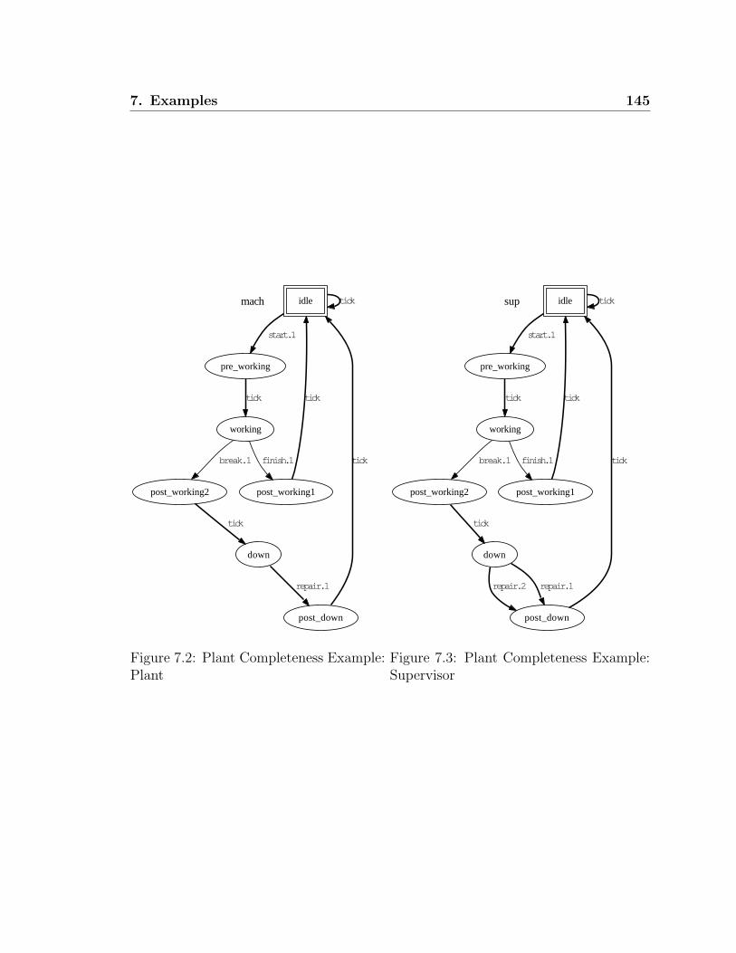
7. Examples 145
mach idle tick
pre_working
start.1
working
tick
post_working1
finish.1
post_working2
break.1
tick
down
tick
post_down
repair.1
tick
Figure 7.2: Plant Completeness Example:Plant
sup idle tick
pre_working
start.1
working
tick
post_working1
finish.1
post_working2
break.1
tick
down
tick
post_down
repair.1 repair.2
tick
Figure 7.3: Plant Completeness Example:Supervisor

146 7. Examples
7.1.2 Activity Loop Free
Figure 7.4 shows a TDES which is not activity loop free, as per Definition 2.3.3. This
is because at state (b) the event down.1 is able to preempt the tick event and proceed
to state (c) and after that to state (a). This creates a tick-less cycle. This cycle of
‘start.1-down.1-repair.1’ can occur an unlimited number of times. This implies the
physically unrealistic situation that we can have an infinite number of these events
occur in a finite time period, and thus must not be allowed.
a
b
start.1 tick
c
down.1
repair.1
Figure 7.4: Activity Loop Example

7. Examples 147
7.1.3 Proper Time Behavior
Figure 7.5 shows a plant which fails to satisfy proper time behavior as per Definition
2.3.5. At state down, neither a tick event nor an uncontrollable event is eligible, just
the controllable event repair.1. This causes two problems: First, it implies that the
controllable event must occur in a particular time frame, yet the event can be disabled
forever by a supervisor, and thus never occur. Second, because its controllable, it can
be disabled by a supervisor. Since no other events are possible, if this event is disabled,
we effectively “stop the clock”, which is physically unrealistic. Note that supervisor
could disable repair.1 here and still be TDES controllable. i.e. this problem is not
caught by the TDES controllability definition.
idle tick
working
start.1
down
repair.1
tick
broken
break.1
tick
Figure 7.5: Proper Time Behavior Example

148 7. Examples
7.1.4 SD Controllability
We now examine the the various points of the SD controllability condition from
Definition 3.2.2.
Point i and Point ii
As Point i and the ‘⇐’ part of Point ii are essentially equivalent to the standard
TDES controllability condition, we will not provide an example here for them. We
will instead focus on the ‘⇒’ part of Point ii as this is a new condition introduced
bu SD Controllability.
Figure 7.6 and Figure 7.7 show a plant and a supervisor such that Supervisor fails
to satisfy the ‘⇒’ part of Definition 3.2.2, with respect to Plant. The prohibitable
event is job and the uncontrollable events are verified and done. We first note that a
tick event is eligible at state 3 in the Plant. Since the prohibitable event job is eligible
at state (Plant:3, Supervisor:3) in the synchronous product, the supervisor should
disable tick at its state 3 since a prohibitable event should only be enabled when it
is to be forced. Alternately, if we do not yet wish event job to occur, it should be
disabled until we are ready for it.
Listing 7.2: OutputChecking SD Controllability
VERI_SD: 0seconds.
(-209) State size of the synchronous product: 12
Number of bdd nodes to store the synchronous product: 38
Computing time: 0 seconds.
failed1: Failed SD Controllability condition II at state:
<failed1_mach1 :3, failed1_sup1 :3>
Point iii.1
Figure 7.8 and Figure 7.9 show a plant and a supervisor such that Supervisor fail to
satisfy Point iii.1 of Definition 3.2.2 with respect to Plant. The only prohibitable
event is job. The uncontrollable events are verified1, verified2, done.In the system, prohibitable event job is eligible at sampling state 1 in the Plant,
so the eligible prohibitable event set for this sampling period is job. However when
we reach state 3, event job has not yet occurred, but is no longer eligible, violating
Point iii.1.

7. Examples 149
0
1
tick
tick
3
verified
2
job
6
job
7
tick
tick
tick
9
job
10
verified
tick
verified
5
tick
4
verified
job
tick
verified
8
tick
done
tick
11
tick
done
tick
Figure 7.6: SD Controllability i, ii Example: Plant
This is a problem as often when a prohibitable event occurs is completely under
the control of the implementation (as discussed before, this is a modeling issue). Also,
this event may occur at different times during a sampling period, depending on the
implementation used. As an SD controller makes its forcing decisions immediately
after a tick, it will cause event job to occur at state 1 in the physical system. If the

150 7. Examples
0
1
tick
3
verified
2
job
6
tick 7
job
9
job
10
verified
tick
tick
verified
4
tick
5
verified
job
verified
8
tick
done
tick
11
tick
done
tick
Figure 7.7: SD Controllability Point i, ii Example: Supervisor
implementation is such that event job is delayed and event verified1 occurs first, we
could get event job after event verified1 in the physical system, which does not match
our plant model.
In this example, it was the plant model that made event job become ineligible. A
related issue would have been if event job was possible at state 3 in the plant, but not

7. Examples 151
in the supervisor. This would imply that the SD controller must detect that event
verified1 has occurred in the current sampling period, and disable event job in time
to prevent it from occurring. This of course cannot be done as the event has already
been initiated after the tick occurred and even if could be stopped, the SD controller
will not even see that event verified1 has occurred until after the next tick, at which
point it would be too late. If the implementation is such that event verified1 occurs
before event job, we would still get a job transition in the current sampling period in
the physical system, violating our control law. For example, if event job was “walk
through doorway”, and event verified1 was “door closes”, this would mean we would
walk into a closed door.
A second related problem this condition can catch is when a prohibitable event
is not eligible at state 1, but becomes eligible at state 3. The supervisor is trying to
express that the event should occur this sampling period, but not until after event
verified1 has occurred. This cannot be implemented as the SD controller would not
know event verified1 had occurred until after the next tick, thus too late to force
a new event. If we tried to simply force the prohibitable event at state one in the
controller, we might get the situation that the event occurs before event verified1
(depending on our implementation). Again, this would violate our control law.
Point iii.2
Figure 7.10 and Figure 7.11 show a plant and a supervisor such that Supervisor fails
to satisfy Point iii.2 of Definition 3.2.2, with respect to Plant. The prohibitable
events are job1, job2. The uncontrollable events are done1, done2.In the system, states 6 and 7 are reached from sampled state 1 by concurrent
strings job1− job2− tick and job2− job1− τ , respectively. As these strings have the
same occurrence image, Point iii.2 requires that states 6 and 7 represent the same
Nerode equivalence cells of the closed loop system’s closed and marked language’s.
However, as strings reaching state 6 can be extended by a done1 event, while strings
reaching state 7 can be extended by a done2 event, the states clearly do not represent
the same Nerode equivalence cell of the system’s closed behavior. Similarly, as strings
reaching state 6 can be extended by a done1 event to a marked string while strings
reaching state 7 can be extended by a done2 event to a marked string, they do not
represent the same Nerode equivalence cell of the system’s marked language either.

152 7. Examples
0
1
tick
tick
3
verified1
2
job
5
tick
4
tick
tick
6
done
tick
7
verified2
8
tick
9
tick
verified1
tick
tick
10
verified1
11
tick
verified1
job
tick
Figure 7.8: SD Controllability Point iii.1Example: Plant
0
1
tick
3
verified1
2
job
5
tick
4
tick
tick
6
done
tick
7
verified2
8
tick
9
tick
verified1
tick
tick
10
verified1
11
tick
verified1
job
tick
Figure 7.9: SD Controllability Point iii.1Example: Supervisor

7. Examples 153
0
1
tick
tick
2
job1
3
job2
tick
4
job2
tick
5
job1
6
tick
7
tick
done1
tick
done2
tick
Figure 7.10: SD Controllability Point iii.2Example: Plant
0
1
tick
2
job1
3
job2
4
job2
5
job1
6
tick
7
tick
done1
tick
done2
tick
Figure 7.11: SD Controllability Point iii.2Example: Supervisor
This condition is important for controllability and nonblocking. The reason is
that an SD controller cannot tell the difference between the two concurrent strings,
so it does not know whether it should be in state 6 or state 7. If events done1 and
done2 were controllable, it would not know if it should be enabling event done1 or
event done2. Clearly, we could not enforce such a control law.
The reason this is important for nonblocking is also that we cannot tell the dif-
ference between the two strings. If we had a sequence of possible concurrent strings
such that each pair had the same occurrence image and only one path of the pair ever
reached a marked state, we would never be able to determine if our system reached
a marked state.
A related issue is how our controller is implemented. The control law says that
either sequence job1 − job2 or sequence job2 − job1 is fine, but not which one will
actually occur. It might be that we will get a bit of both, but we might always get
only one due to timing issues; or perhaps we have a sequential implementation that
knows that job1 and job2 must occur, so its designers choose the order job1− job2,
and the implementation always executes these events in this order. If the sequence
job2−job1 was the only path back to a marked state, the implementation would block
despite the fact the TDES system was nonblocking. This condition, in conjunction

154 7. Examples
with Point iv of the SD controllability definition, helps make sure nonblocking does
not depend on the order of the events and allows things to function if we only get one
of the variations of the possible concurrent strings with the same occurrence image.
One can image that we have a family of possible physical systems that we could get
based on how we implement our controllers, each differing based on which of the
possible variations of the concurrent strings can actually occur. We are assuming we
will see at least one variation, possibly more. These conditions are intended to ensure
that whichever system we get, it will still be nonblocking if the TDES system was
nonblocking.
Listing 7.3: Output...
(-211) State size of the synchronous product: 8
Computing time: 0 seconds.
failed1: Failed SD Controllability condition III.2 at state:
<failed1_mach :6, failed1_sup :6>
<failed1_mach :7, failed1_sup :7>
list_NerFail is not empty and RecheckNerodeCells () Failed.
Point iv
Figure 7.12 and Figure 7.13 show a plant and a supervisor such that Supervisor
fails to satisfy Point iv in Definition 3.2.2 with respect to Plant. Since state 0 is a
marked state and is reached from state 6 by activity event done, the system does not
satisfy the condition as clearly its marked language is not a subset of the sampled
strings (empty string and strings ending in a tick).
If a marked state is reachable by a non-tick event, it means the system can reach
a marked state in a way that is invisible to the SD controller as it can only observe
sampled strings. This by itself is undesirable, as we could have a system that can only
reach marked states by non-tick events and we would never be able to tell if we had
actually reached a marked state. Also, if we have multiple concurrent strings with
the same concurrence image, we could have the situation that only some of them pass
through a marked state in that sampling period. Worse, our implementation might
be such that we only get the variations that do not pass through a marked state! Note
also, that Point iii.2 of the SD controllability definition only says that concurrent
strings with same occurrence image must have same marked future. it does not say

7. Examples 155
0
1
tick
tick
2
job1
3
job2
tick
4
job2
tick
5
job1
6
tick tick
done
tick
Figure 7.12: SD Controllability Point ivExample: Plant
0
1
tick
2
job1
3
job2
4
job2
5
job1
6
tick tick
done
tick
Figure 7.13: SD Controllability Point ivExample: Supervisor
much about the prefixes of these concurrent strings. That is where Point iv comes
in, making sure the Σ+act prefixes are not marked.
Listing 7.4: OutputVERI_SD: 1seconds.
(-212) State size of the synchronous product: 7
Number of bdd nodes to store the synchronous product: 20
Computing time: 1 seconds.
failed1: Failed SD Controllability condition IV at state:
<failed1_mach :0, failed1_sup :0>
There is a reachable marking state reached by a non -tick event.

156 7. Examples
7.2 SD Controlled Flexible Manufacturing System
In this section we present a working example based on the untimed Flexible Manufac-
turing System (FMS) from [11]. The system, shown in Figure 7.14, is composed of six
plant components and five one slot buffers. We will treat the buffers as specifications,
requiring that they do not overflow or underflow. Table 7.1 below shows a mapping
from the event labels used in the diagrams to their meaning. The events labeled as
numbers are directly from the Hill untimed example. We kept the same labeling to
make it easy to see the correspondence.
Figure 7.14: Flexible Manufacturing System Overview
7.2.1 FMS Plants
The plant components consist of two conveyors (Con2 and Con3), a handling robot
(Robot), a lathe that can produce two different parts, a painting machine (PM),
and a finishing machine (AM). The flow of material is illustrated in Figure 7.14. See
Figures 7.15 - 7.20 for the TDES models of the components.

7. Examples 157
Table 7.1: Explanation of Event Labels
Label Meaning Label Meaning Label Meaning
921 Part enters system 922 Part enters B2 933 Robot takes from B2
934 Robot to B4 937 B4 to Robot for B6 939 B4 to Robot for B7
938 Robot to B6 930 Robot to B7 951 B4 to Lathe (A)
953 B4 to Lathe (B) 952 Lathe to B4 (A) 954 Lathe to B4 (B)
971 B7 to Con3 974 Con3 to B7 972 Con3 to B8
973 B8 to Con3 981 B8 to PM 982 PM to B8
961 Initialize AM 963 B6 to AM 965 B7 to AM
966 Finished from B7 964 Finished from B6
1 tick
2
921
3
tick
tick
4
922
tick
Figure 7.15: Conveyor - Con2
1 tick
2
933
3
937
4
939
5
tick
6
tick
7
tick
tick
8
934
tick
938
tick
930
tick
Figure 7.16: Robot
7.2.2 Buffer Supervisors
We now discuss the TDES supervisors, shown in Figures 7.21 - 7.25, that control the
flow of parts in and out of the buffers. Their goal is to make sure the buffers do not
overflow or underflow. They are based on the original untimed buffer specification of
[11], but extended to the SD controllable setting. In some of the supervisors in this
section such as B4 in Figure 7.22, we have activity events selflooped (i.e. event 933
at state 0 of B4). This will not cause the system to have an activity loop, as it will
be combined with the plant TDES which only allow these events to occur once per
clock cycle.
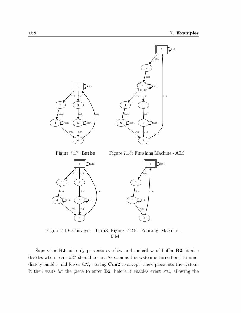
158 7. Examples
1 tick
2
951
3
953
4
tick
5
tick
tick
6
952
tick
954
tick
Figure 7.17: Lathe
1 tick
2
961
3 tick
4
963
5
965
tick
6
tick
7
tick
tick
8
964
tick
966
tick
Figure 7.18: Finishing Machine - AM
1 tick
2
971
3
973
4
tick
5
tick
tick
6
972
tick
974
tick
Figure 7.19: Conveyor - Con3
1 tick
2
981
3
tick
tick
4
982
tick
Figure 7.20: Painting Machine -PM
Supervisor B2 not only prevents overflow and underflow of buffer B2, it also
decides when event 921 should occur. As soon as the system is turned on, it imme-
diately enables and forces 921, causing Con2 to accept a new piece into the system.
It then waits for the piece to enter B2, before it enables event 933, allowing the

7. Examples 159
0
1
921
6
no921
2
tick
tick
tick
3
922
4
tick
tick
5
933
tick
Figure 7.21: Supervisor B2
Robot to remove the part. It does not cause another 921 to occur until 933 does,
ensuring that the buffer is empty. A few things are worth noting. First, B2 enables
prohibitable event 933, but does not disable the tick at state 4. This tells us that it
wants to prevent the event from occurring too soon, but does not decide when the
event will actually occur. This is controlled by another supervisor. Second, B2 makes
sure there is a tick between 933 occurring, and enabling and forcing event 921. This
is to satisfy Point iii.1 of the SD controllability definition. Third, Supervisor B2
contains a special event, no921, which we will discuss in a later section. This is a
“virtual event” that was not part of the original plant, but that we added to aid in
communication between supervisors.
Supervisors B4, B6, and B7 manage their respective buffers. They strictly disable
and enable events to prevent buffer overflow and underflow. They do not force any
events, telling us that other supervisors make these decisions. This is because the
decision of when these events should occur requires more than just a local view of
whether a buffer is empty or not. We will discuss these other supervisors in later
sections.

160 7. Examples
0 933 tick
1
934
2
952
3
954 951 953
tick
937
tick
939
tick
Figure 7.22: Supervisor B4
0 937 tick
1
938 963
tick
Figure 7.23: Supervisor B6
0 939 973 tick
1
930
2
974 971
tick
965
tick
Figure 7.24: Supervisor B7
0 tick
1
930
2
tick
3
971
4
tick
tick
5
972
6
tick
7
981
8
tick
tick
9
982
10
tick
11
973
tick
Figure 7.25: Supervisor B8

7. Examples 161
Supervisor B8 not only prevents overflow and underflow of buffer B8, it also
controls the flow of pieces once a part enters buffer B7 (event 930 ), flows to TDES
PM, and then back to buffer B7. It does this by watching the parts progress, and
then forcing events 971, 981, and 973 as needed. As B8 determines when these events
occur, it disables tick as soon as it enables these events to comply with Point ii of
the SD controllability definition. In other words, once the event is enabled by all the
supervisors and possible in the plant, the event is also forced.
The fact that the supervisor must not only decide when to enable an event, but
also when to force the event, makes things more complicated. It must not only decide
when to enable the event, but also must know that the event is not disabled by
another supervisor and that it is eligible in the plant. Otherwise, it could disable a
tick when the desired event cannot occur, either forcing the wrong event or becoming
uncontrollable.
7.2.3 B4 to Lathe Path
In addition to the buffer supervisors we represented in Section 7.2.2, we need to add
the following supervisors to resolve some nonblocking and concurrency issues on the
B4 to lathe part path of Figure 7.14.
We first need to address a nonblocking issue with respect to buffer B4 and B2.
We see from Figure 7.14 and Figure 7.16, that Robot takes a piece from buffer B2
(event 933 ), and places it in B4. The piece then goes to the Lathe, and then back
to buffer B4. The robot will then take the piece from B4, and put it in either buffer
B7 (event 930 ), or buffer B6 (event 938 ).
There are two issues here. The first issue is how to decide which action the
Robot should take if both buffer B2 and buffer B4 have a part waiting. In normal
supervisory control theory, we can just enable the safe choices, and allow the plant to
somehow make the decision. However, we want to be able to convert from a TDES
supervisor to an SD controller in an easy, deterministic fashion. This means we must
dictate which prohibitable events occur, and in which sampling period they occur in.
We thus have to choose to service either buffer B2 or B4, as we cannot do both at
the same time.
This issue is handled by supervisor TakeB2, shown in Figure 7.26. It forces

162 7. Examples
Robot to first service buffer B2, then buffer B4, then back to buffer B2. It waits
until there is a piece in B2 (event 922 ), then it immediately enables and forces event
933 to move the piece to buffer B4. It then waits until the piece goes to the Lathe,
returns to B4, and then moved to either B6 or B7, before it allows the Robot to
service B2 again.
0 tick
1
922
2
tick
3
933
4
tick
tick
5
922
6
930 938
tick
7
930 938
tick
922
tick
Figure 7.26: TakeB2
0 933 tick
1
934 937 939
tick
Figure 7.27: B4Path
The second issue is to prevent a conflict with respect to buffer B4. Once the
Robot puts a piece in B4 and the piece is taken by the Lathe, the Robot could
put a second piece in B4. This would mean the Lathe has no place to return its
part, and the system blocks. TakeB2 prevents this by disabling event 933 until the
current part has returned to B4, and then removed to either B6 or B7.
We now discuss supervisor B4Path. It works with buffer supervisor B4 to ensure
the proper behavior of the B4 to lathe part path. Supervisor B4 primarily ensures
that buffer B4 does not overflow or underflow. It serves an additional role in making

7. Examples 163
sure that once a piece is put in B4, the correct action is taken when it is taken out.
When the robot initially puts a piece in B4 (event 934 ), it makes sure that only
events 951 and 953 can be used to take the piece out. This ensures the part goes to
the Lathe for processing. The Lathe can process the piece as type A (event 951 )
or type B (event 953 ), producing different results. The Lathe then returns the part
to B4 using events 952 (part is type A) or event 954 (part is type B). Since type
A parts go to buffer B6 (events 937 then 938 ), and type B parts (event 939 then
930 ) must go to buffer B7, supervisor B4 ensures only the correct follow up event
is possible. B4Path contributes to the proper behavior of the B4 to lathe path, by
disabling event 933 once a part is put into B4 from B2, and disabling events 937
and 939 until a part is placed into B4 from B2.
0 tick
1
934
2
tick
3
951
4
tick
tick
5
934
6
tick
7
953
tick
Figure 7.28: LathePick
164 7. Examples
Supervisor LathePick, shown in Figure 7.28, also contributes to control of the
B4 to lathe part path. To satisfy Point ii of SD controllability, we cannot just enable
both event 951 and 953 and let the system “decide.” We have to dictate when these
events are to occur. That means we have to make a choice. In LathePick, we have
required that the Lathe first produce a type A part, then a type B part, and then
alternate. Note that the supervisor has enough information to know when the events
are possible in the plant, so it does not try to force them at the wrong time, possibly
“stopping the clock.”
7.2.4 Moving Parts from B4 to B6/B7
We now discuss some concurrency and blocking issues involved with moving pieces
from buffer B4, to either buffer B6 or B7. To move a part from buffer B4 to B6,
we use event 937. To satisfy Point ii of SD controllability, we need to decide when
to enable and force this event. This is handled by supervisor TakeB4PutB6, shown
in Figure 7.29. It waits for event 952 to occur, which signifies a piece of type A is
ready to be transferred to buffer B6. It forces event 937 and then waits for event
963 to occur, signifying that the piece has been taken by AM and that B6 is ready
for a new part.
We now consider moving a part from B4 to B7. We do this using event 939. We
have to decide when to force 939 in order to satisfy Point ii of SD controllability,
but we also have to deal with a potential blocking situation. Because a part placed in
B7 first goes to PM for processing, it is possible that the robot could put a part in
the now empty buffer B7, leaving no place for the first part to return to. Supervisor
TakeB4PutB7, shown in Figure 7.30, handles both issues. It watches for event 954
to occur, signaling that a part of type B has been placed in B4, and is ready to be
transferred to buffer B7. TakeB4PutB7 forces event 939 to make the transfer. It
then waits for event 965 to occur signaling that AM has removed the part from B7,
before allowing another 939 to occur, thus preventing blocking.
7.2.5 AM to Exit Path
We now discuss the paths from B6 and B7, leading through machine AM and then to
where the parts exit the system. We have several concurrency issues to deal with here.

7. Examples 165
0 tick
1
952
2
tick
3
937
4
tick
963
tick
5
952
963
tick
Figure 7.29: TakeB4PutB6
0 tick
1
954
2
tick
3
939
4
tick
965
tick
5
954
965
tick
Figure 7.30: TakeB4PutB7
First, we have to specify when prohibitable events 961, 963, and 965 are suppose to
occur in order to satisfy Point ii of SD controllability. This is complicated by the
fact that a piece could be waiting for AM in both B6 and B7, so we need to specify
how to choose which buffer to service first.
The problem is that these three events are linked and we have to keep track of
several issues in order to decide when to force which event. We could create a single
supervisor to do this, but it would be quite large and complicated, thus difficult to
design correctly. It would be nice to be able to design several modular supervisors.
If we were only enabling and disabling events, this would not be that hard. However,
since we must decide when to force the events, we have to make sure we do not try to
force an event when it is not possible in the plant, or disabled by another supervisor.
It was very non-obvious how to do this modularly, without significant reuse of logic
from other supervisors.
We then came up with the solution of using prohibitable “virtual events” no963a,
no963b, no965a, and no965b. We introduced these new events to the system by adding
plants AddNo963 and AddNo965, shown in Figures 7.31 and 7.32. Note that we

166 7. Examples
made sure the plants specify that these events can only occur once per sampling
period, so that we do not have to specify this in our supervisors.
1 tick
2
no963a no963b tick
Figure 7.31: Plant AddNo963
1 tick
2
no965a no965b tick
Figure 7.32: Plant AddNo965
Let’s first discuss how to handle event 963. The idea is that when we want to
disable the tick to force event 963 in one supervisor, events no963a/b can be used
as an alternate event to force if event 963 is disabled by another supervisor, or not
possible yet in the plant. The other supervisors will only enable event no963a or
no963b when they know 963 is not possible, and they will make sure only one of the
three events are possible at a given time. The reason there is an ‘a’ and ‘b’ event
is that there are three supervisors with which we need to coordinate enablement
information. This will become clear later.
The primary supervisor for event 963 is Force963, shown in Figure 7.33. It
watches for event 938 to occur, signifying that there is a part in B6 waiting to go
to AM. The supervisor then disables the tick to force 963. Note, that it is the
only supervisor that tries to force this event. However, event 963 could be ineligible
in plant component AM, or disabled by supervisors Force961 or AMChooser,
the latter two TDES shown in Figures 7.34 and 7.35. Force963 has no way of
knowing this. It handles this by adding the no963a/b-tick loop at state 2. Supervisors
Force961 and AMChooser will ensure that out of events 963, no963a, and no963b,
one and only event will be eligible and enabled immediately after a tick. If 963 is
ineligible or disabled, then no963a or no963b gets forced instead, and then we try
again after the tick. This way we signal we want 963 to occur as soon as it can, but
do not stop the clock. We also do not need to repeat information from the plant and
other supervisors about when these events are eligible/enabled.
The reason that only one of the three events are ever allowed to be eligible/enabled
at the start of a tick, is to avoid violating Point iii.1 of the SD controllability
definition. Examining state 2 of Force963, we see that once one of the three events

7. Examples 167
occurs, the others are disabled. If more than one was enabled and eligible at state
2, this would cause one of them to change eligibility status between ticks, violating
Point iii.1 of the SD controllability definition.
For event 965, we have similar behavior represented by supervisor Force965,
shown in Figure 7.36. It interacts in a similar way with plant component AM, and
supervisors Force961 and AMChooser.
0 tick
1
938
2
tick
4
no963a no963b
3
963 tick
tick
Figure 7.33: Force963
0 no963a no965a
1
961
2 tick no963b no965b
3
965 963
tick
no963a no965a
no963b no965b
4
tick
tick no963a no965a
5
964 966
tick
no963a no965a
Figure 7.34: Force961
We now discuss supervisor Force961, shown in Figure 7.34. Its primary task is
to determine when to force event 961 which readies AM to process parts. Force961
forces 961 right away, and then waits for events 964 or 966 (signifies AM has finished
processing the part) to occur, before forcing event 961 again.
The secondary task of Force961 is to only enable events no963a and no965a
when events 963 and 965 are not possible in the plant component AM. When they
are possible in the plant, Force961 enables no963b and no965b instead. This insures
that events no963a and no965a will always be possible after a tick when events 963
and 965 are ineligible in the plant. It also ensures that the ‘a’ and ‘b’ events are never

168 7. Examples
0 tick no963b no965b
2
938
1
974
no963b no965b
3
974
5
tick
no963b no965b
938
6
tick
no963b no965b
7
tick
tick no963b
13
938
12
965
tick no965b
11
963
9
974
tick no963b
8
965
4
tick
no963b
tick
no965b
10
974
tick no965b
963
965
tick no963b
tick
938
no963b
tick
no963b
tick
no965b
Figure 7.35: AMChooser
0 tick
1
974
2
tick
4
no965a no965b
3
965 tick
tick
Figure 7.36: Force965
eligible at the same time. Also, as supervisor AMChooser ignores the ‘a’ events,
they will never be disabled when Force961 needs them. As Force961 never disables

7. Examples 169
the ‘b’ events when 963 and 965 are possible in the plant, this ensures that they will
not be disabled when AMChooser needs them. This means the two supervisors do
not interfere with each other with respect to these events.
Finally, please note that when we switch from the ‘a’ to the ‘b’ events in Force961,
we only do so immediately after a tick (consider states 1 to state 4 as an example).
This is to not violate Point iii.1 of the SD controllability definition.
We now consider our last supervisor for this section, AMChooser, shown in
Figure 7.35. The role of this supervisor is to choose between taking a piece from
buffer B7 (event 965 ) or buffer B6 (event 963 ), when both have a waiting part. If
both receive a part in the same sampling period, we take the piece from buffer B7
first as there are other machines to keep busy along the B7 to PM path. We then
take a piece from B6. If there is already a new piece from B7 waiting, we continue in
an alternating fashion. If there is only one piece waiting in a given sampling period,
then we handle that piece. Because AMChooser sometimes disables event 963 or
965 in order to enforce this order, it enables the appropriate no963b or no965b event
as a forcing substitute. It also ensures that event 963 and no963b are never enabled
at the same time. It behaves similarly for events 965 and no965b.
7.2.6 System Shutdown
When we tested the previous supervisors (excepting supervisor B2 originally did not
have its state 6, plant component AM was not marked at its state 3, and supervisor
Force961 was not marked at its state 2) we found that the system was blocking. It
was not that the system was deadlocking or not completing its tasks, it was simply
the fact that, due to forcing events as soon as they were ready, the entire system was
never in a marked state at the same time. We could have delayed some events to
achieve this, but that would have been less efficient.
The real cause was the fact that the system did not have a shutdown mechanism.
Once started, it just kept running. A shutdown mechanism would cause the system
to empty out, allowing a non-deadlocked/livelocked system to return to its idle state.
The easiest way to cause the system to go idle, is to prevent plant component Con2
from taking new parts (event 921 ). Once new parts stopped coming in, the system
would process the existing ones, allow them to leave, and then the TDES should

170 7. Examples
return to their idle states which are marked.
To achieve this, we added a new plant component SystDownNup, shown in
Figure 7.37. It contains an event shutdown to empty the system, and an event restart
to bring the system back up. This could correspond to a physical switch an operator
could throw to control this behavior.
1 tick
2
shutdown
3
tick
tick
4
restart
tick
Figure 7.37: Plant SystDownNup
0 921 tick
1
shutdown
921
2
tick
no921 tick
3
restart
tick
no921
Figure 7.38: Supervisor handleSystDown
Our next task was to stop new pieces from entering the system. The problem
was that supervisor B2 forced event 921, causing Con2 to take a new part, as soon
as buffer B2 was empty. As we wanted to keep supervisor B2 simple, we added
a new prohibitable “virtual event,” no921. This was introduced by adding plant
AddNo921, shown in Figure 7.39. We then added the no921 -tick loop at state 0 of
supervisor B2. We would use event no921 as an alternate event to force, when we
disabled event 921.
1 tick
2
no921 tick
Figure 7.39: Plant AddNo921
Finally, we added supervisor handleSystDown, shown in Figure 7.38. Its job
was to enable event 921 and disable no921 initially, and then disable 921 and enable

7. Examples 171
no921 once the shutdown event occurs. When the restart event occurs, the process
is reversed. We also make sure events 921 and no921 are never enabled at the same
time, and that one of the two are always eligible and enabled immediately after a
tick.
However, after the above, we were still nonblocking. The culprit was supervisor
Force961. As soon as event 961 was eligible, it was forced so that AM was ready
to process a part. We could have created a no961 event like we did for B2, but this
would have been trickier as we needed to allow enough 961 events to occur to allow
the existing pieces to leave. Rather than do this, we decided that for AM, state 3
was a rest state, and it was fine to leave it there. So, we marked state 3 of AM,
and state 2 of Force961, and the system was nonblocking. Note that we could have
marked state 2 of TDES AM, and state 1 of TDES Force961, but that would have
caused Point iv of the SD controllability definition to fail.
7.2.7 Algorithm Runtime Statistics
To test the performance of the algorithm on this example, the following machine
configuration was used:
• 1.8GHz Dual core AMD processor
• 4GB of Dual channel DDR2 RAM
• Cygwin 1.5.25-15 with gcc version 4.3.2
For testing purpose, the source code is compiled with -O3 optimization1.
As we can see from the log output for the FMS example, shown in Listing 7.5, our
supervisor S is SD controllable for our plant. We also see that our plant has proper
time behavior, is complete for our supervisor, and has S-singular prohibitable behav-
ior. Finally, we see that our closed loop system is ALF and nonblocking. From the
log, the total number of states of the synchronous product is 82,608. The verifications
take about 2 minutes and 51 seconds. The memory usage is around 183 megabytes
at the highest point, as shown in Figure 7.40. For the input files of all the DES in
this example, please see the appendix.
1More information can be found by running man gcc.

172 7. Examples
Listing 7.5: Output*************************************************
Bdd -based TDES Verification Tool
*************************************************
L - Low Level verification
F - File the current project
C - Close the current project
Q - Quit
*************************************************
Current Project: FMS_1.sub
Procedure desired:
Show the blocking type(may take long time)(Y/N)?
Verbose level (0 - disable , 1 - brief , 2 - full)?
Computing reachable subpredicate ...
R: Iteration_1 nodes: 120 time: 0 s states: 10
R: Iteration_2 nodes: 586 time: 0 s states: 77
R: Iteration_3 nodes: 1754 time: 0.031 s states: 772
R: Iteration_4 nodes: 2801 time: 0.093 s states: 4531
R: Iteration_5 nodes: 3265 time: 0.172 s states: 26540
R: Iteration_6 nodes: 3310 time: 0.109 s states: 48300
R: Iteration_7 nodes: 2281 time: 0.094 s states: 58068
R: Iteration_8 nodes: 2387 time: 0.062 s states: 62420
R: Iteration_9 nodes: 2132 time: 0.047 s states: 68242
R: Iteration_10 nodes: 1983 time: 0.047 s states: 76780
R: Iteration_11 nodes: 1546 time: 0.015 s states: 82128
R: Iteration_12 nodes: 1330 time: 0.016 s states: 82608
R: Iteration_13 nodes: 1330 time: 0 s states: 82608
R: 0seconds.
bddReach states :82608
bddReach Nodes :1330
Verifying controllablity ...
VERI_CON: 0seconds.
Verifying Nonblocking ...
CR: Iteration_1 nodes: 191 time: 0 s states: 24
CR: Iteration_2 nodes: 357 time: 0.016 s states: 70
CR: Iteration_3 nodes: 488 time: 0.015 s states: 190
CR: Iteration_4 nodes: 540 time: 0.016 s states: 394
CR: Iteration_5 nodes: 785 time: 0.031 s states: 540
CR: Iteration_6 nodes: 1143 time: 0.047 s states: 773
CR: Iteration_7 nodes: 1757 time: 0.093 s states: 3545
CR: Iteration_8 nodes: 2805 time: 0.281 s states: 28173
CR: Iteration_9 nodes: 2080 time: 0.203 s states: 47358
CR: Iteration_10 nodes: 2048 time: 0.172 s states: 67045
CR: Iteration_11 nodes: 1552 time: 0.109 s states: 81732
CR: Iteration_12 nodes: 1330 time: 0.031 s states: 82608
CR: Iteration_13 nodes: 1330 time: 0.047 s states: 82608
VERI_NONBLOCKING: 2seconds.
Checking Plant Completeness ...
VERI_BALEMI: 0seconds.
Verifying Activity Loop Free ...
Garbage collection #1: 2000003 nodes / 1996580 free / 0.1s / 0.1s total
VERI_ALF: 7seconds.
Verifying Proper Timed Behavior ...
VERI_PTB: 0seconds.
Checking SD Controllability
VERI_SD: 162 seconds.
(0) This system has been verified succesfully!
State size of the synchronous product: 82608
Number of bdd nodes to store the synchronous product: 1330
Computing time: 171 seconds.
Total computing time :171 seconds.
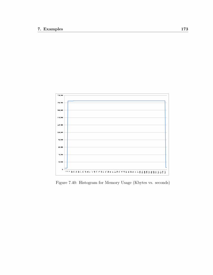
7. Examples 173
Figure 7.40: Histogram for Memory Usage (Kbytes vs. seconds)

174 7. Examples
7.3 Translating FSM Supervisors to Moore FSM
In Section 7.2, we presented an example of a Flexible Manufacturing System with SD
controllable TDES supervisors. In this section, we apply the method in Section 4.2
to translate individual FMS supervisors into Moore finite state machines (FSM) (see
Section 4.1). This is possible because our supervisor is SD controllable, and our plant
is complete for our supervisor. If the plant was not complete, we would have had to use
additional information from the plant components to determine when the problematic
prohibitable events were not possible in the plant. This can be accomplished by
converting the plant components that contain the needed information into FSM as
well, and combining them with the FSM for the supervisors as modular controllers.
7.3.1 Adding More Timing Information
Before we can translate the individual TDES supervisors into FSM, they must be CS
deterministic as in Definition 3.1.5 and non-selfloop ALF. A TDES is non-selfloop
ALF if once any activity selfloops are removed, the resulting TDES is ALF. For
example, supervisor B4 in Figure 7.22 is neither CS deterministic or non-selfloop
ALF. This is a problem as the possible next state transitions of the FSM are too
numerous, and many of them are not actually possible in the plant. For example,
we could have according to the TDES a 934 -tick sequence, a 934 -951 -tick, or even a
934 -951*-tick sequence. We simply have too many choices, and this would result
in an overly complex FSM. Also, concurrent strings 934 -951 -tick and 934 -951 -934 -
tick have the same occurrence image but lead to different states, which would result
in a nondeterministic controller. Examining the plant and other supervisors, we see
that there will always be a tick between events 934 and 951, so we can add this to
TDES B4, as we have done in Figure 7.41.
Making similar observations for the other non-selfloop activity loops, we get the
supervisor in Figure 7.41 which should provide us with the same over all closed loop
behavior as the original B4 supervisor. However, we note that prohibitable event 933
is still selflooped at state 0, so the TDES is not ALF. We could modify the supervisor
to remove this loop, but we do not need to as the selfloop provides enablement
information, but does not affect the next state information. As such, it does not
impede our translation. i.e. our next state information is 933*-934 -tick to state

7. Examples 175
1 of B4. Essentially, as long as the supervisor is CS deterministic and non-selfloop
ALF, we can do the translation. As was discussed in Chapter 4, all we require is that
the TDES be CS deterministic, but typically if the TDES is not non-selfloop ALF
it will also not be CS deterministic. Also, it is often difficult to even check the CS
deterministic condition if the TDES is not non-selfloop ALF.
We then made similar changes to supervisors B6, B7, and B4Path. The new su-
pervisors are shown in Figures 7.42 - 7.44. All remaining supervisors can be converted
directly. We reran our software on the FMS system with these new supervisors, and
all conditions still passed.
0 933 tick
5
934
6
952
7
954
1
tick
2
tick
3
tick
tick
8
951 953
tick
937
tick
939
tick
Figure 7.41: New B4
0 937 tick
3
938
1
tick
tick
4
963
tick
Figure 7.42: New B6
0 939 973 tick
5
930
7
974
1
tick
2
tick
tick
6
971
tick
tick
8
965
tick
Figure 7.43: New B7
0 933 tick
2
934
1
tick
tick
3
937 939
tick
Figure 7.44: New B4Path

176 7. Examples
7.3.2 FSM Controllers for Flexible Manufacturing System
This section lists all the FSM Controllers for the Flexible Manufacturing System we
presented in Section 7.2 and 7.3.1, using the method developed in Section 4.2. We
first briefly discuss some implementation and modeling details, as well as introduce
some notation that we will use.
Each FSM samples its inputs on the clock edge when tick occurs, and then changes
state based on its current state, the value of each relevant input, and the next state
arcs for that state. The timing info is implicit as it only changes state on a clock edge.
If an input for an event is true when sampled on the clock edge, then it is considered
to have occurred during the last clock period. The designer must make sure that the
input for a given value has a pulse length equal to the period of our clock so that the
input will not be lost. If an input is seen at two clock edges in a row, it is considered
to have occurred twice. As such, the designer must make sure an input does not
have an overly long pulse length. Remember, except for one exception, an event is
considered to occur when its input goes true at the controller. The exception is when
the input goes true so close to a sampling edge it is detected in the next sampling
period, then it is considered to have occurred in the next clock period. This should
be taken in to account in modeling the system.
To represent the FSM visually, the following notations are defined. For the given
FSM,
• At each state in the FSM, a prohibitable event is listed if its corresponding
output is true at that state, which means the controller enables this event at
this state. An event is not listed if its output is false.
• At each transition, we use logical operators to represent the sampled input. We
use ‘!’ as NOT, ‘+’ as OR, ‘·’ as AND.
• To distinguish from a DES event label and the event input being true at the
clock edge, the event name is surrounded by ‘[ ]’ to indicate that the input was
true at the clock edge.
If the controller is following a concurrent string, for example α− β − τ from one
sampling state to the next, we add a transition arc with ‘·’(AND) between the non-
7. Examples 177
tick events. For example ‘[α] · [β]’.2 This would be interpreted as events α and β
occurred in the last sampling period, and no other activity events. Of course, there
is no implied ordering of the two events, nor do we know how many times each event
actually occurred during the last clock period.
Technically, if a supervisor has event set Σ = α, β, γ, tick, the next state condition
for a given concurrent string should include a term for each activity event in the event
set. When the event is missing, it is negated. For string α − β − τ , this would be
‘[α] · [β]·![γ]’. However, we can often simplify these equations using Boolean logic.
For instance, if none of the possible strings at the current sampled state contain γ,
we can leave it out of the equations.
If the controller is getting to the same state by different strings which are not
occurrence equivalent, then we can use ‘+’(OR) to combine the conditions together.
For example ‘[α] + [β]’. This would be interpreted as event α or event β occurred in
the last sampling period, but no others.
If at a given state in the controller we can do concurrent string α−τ and α−β−τ ,
we need to make sure their next state equations do not overlap. Using conditions ‘[α]’
and ’[α] · [β]’ is not enough as first condition is true as long as α occurred, irrespective
of β. Instead, the condition for α− τ should be ’[α]·![β]’.
For each FSM, the initial state is identified by a Reset signal. This Reset sig-
nal represents the “power on” behavior or a restart of the controller. This state is
equivalent to the initial state of each TDES. It also explains why the initial state of
a timed DES is a sampling state that does not need to be reached by a tick, since the
FSM always starts at this state.
For each FSM state, we typically define a default transition DEF. This is because
a TDES transition function is a partial function and an FSM next state function is
a total function. Basically, it is a shorthand for all the next state equations that
we have not explicitly specified. It is equivalent to taking the logical OR of all
existing outgoing next state conditions from that state, and then negating the result.
Sometimes, when we are translating a supervisor, we end up with a specified next
state equation going to the same place as our DEF transition. That means this
transition can be removed as it will be covered by the DEF condition.
2In the following FSM graphs, this operator is represented by ‘.’(period) instead of ’·’ due to atechnical difficulty.

178 7. Examples
Our first FSM is for supervisor B2, and is shown in Figure 7.45. At state 0, we
have merged selfloop transition ‘![921] · [no921]’ with the DEF transition. It is worth
noting how much simpler the FSM tends to be than the corresponding supervisor.
For B2, we went from a 7 state supervisor to a 3 state FSM.
state: 0 921
no921
Reset
DEF
state: 1
[921].![no921]
DEF
state: 2 933
[922]
[933]
DEF
Figure 7.45: FSM B2
state: 0
Reset
DEF
state: 1 963
no963a no963b
[938] [963].!([no963a]+[no963b])
DEF
Figure 7.46: FSM Force963
We do a similar simplification for supervisors Force963 and Force965. The
translated FSM are shown in Figures 7.46 and 7.47. For Force963, we should have
a ![963] · ([no963a] + [no963b]) selfloop at state 1, but we have absorbed this into the
DEF transition. For Force965, we have absorbed the ![965] · ([no965a] + [no965b])
transition at state 1, into the DEF transition.
state: 0
Reset
DEF
state: 1 965
no965a no965b
[974] [965].!([no965a]+[no965b])
DEF
Figure 7.47: FSM Force965
state: 0 933
Reset
DEF
state: 1 951 953
[934]
state: 2 937
[952]
state: 3 939
[954] [951]+[953]
DEF
[937]
DEF
[939]
DEF
Figure 7.48: FSM B4
The next translation we examine is for B4, and the FSM are shown in Figure
7.48. Note at state 0, we have a transition to state 1 with condition ‘[934]’. Strictly

7. Examples 179
speaking this should be ‘[934]·![952]·![954]’. However, after examining the plant and
other supervisors, we know that these three events can never occur in the same clock
period. We can thus simplify this to ‘[934]’ to keep our diagram simple. Similar for the
‘[952]’ and ‘[954]’ transitions. A similar example is at state 1. Here we have transition
condition ‘[951] + [953]’. Strictly speaking, this should be ‘[951]·![953]+![951] · [953]’
but we know from the plant that these events can’t occur in the same clock period,
so we can simplify things.
The translation of the remaining FSM are straightforward so we do not need to
discuss them individually. The translations for supervisors B6, B7, B8, LathePick,
TakeB2, B4Path, Force961, handleSystDown, TakeB4PutB6, TakeB4PutB7,
and AMChooser are shown in Figures 7.49 - 7.59.
state: 0 937
Reset
DEF
state: 1 963
[938] [963]
DEF
Figure 7.49: FSM B6
state: 0 939 973
Reset
DEF
state: 1 971
[930].![974]
state: 2 965
![930].[974] [971]
DEF
[965]
DEF
Figure 7.50: FSM B7

180 7. Examples
state: 0
Reset
DEF
state: 1 971
[930]
DEF
state: 2
[971]
DEF
state: 3 981
[972]
DEF
state: 4
[981]
DEF
state: 5 973
[982]
[973]
DEF
Figure 7.51: FSM B8
state: 0
Reset
DEF
state: 1 951
[934]
DEF
state: 2
[951]
DEF
state: 3 953
[934]
[953]
DEF
Figure 7.52: FSM LathePick
state: 0
Reset
DEF
state: 1 933
[922]
DEF
state: 2
[933]
([938]+[930]).![922]
([938]+[930]).[922]
DEF
state: 3
!([938]+[930]).[922]
[938]+[930]
DEF
Figure 7.53: FSM TakeB2
state: 0 933
Reset
DEF
state: 1 937 939
[934] [937]+[939]
DEF
Figure 7.54: FSM B4Path

7. Examples 181
state: 0 961
no963a no965a
Reset
DEF
state: 1 963 965
no963b no965b
[961]
DEF
state: 2 no963a no965a
[963]+[965]
[964]+[966]
DEF
Figure 7.55: FSM Force961
state: 0 921
Reset
DEF
state: 1 no921
[Shutdown] [Restart]
DEF
Figure 7.56: FSM handleSystDown
state: 0
Reset
DEF
state: 1 937
[952]
DEF
state: 2 963
[937]
[963].![952]
[963].[952]
DEF
state: 3 963
![963].[952]
[963]
DEF
Figure 7.57: FSM TakeB4PutB6
state: 0
Reset
DEF
state: 1 939
[954]
DEF
state: 2 965
[939]
[965].![954]
[965].[954]
DEF
state: 3 965
![965].[954]
[965]
DEF
Figure 7.58: FSM TakeB4PutB7

182 7. Examples
state: 0 no963b no965b
Reset
DEF
state: 1 965
no963b
[938].[974]
state: 2 963
no965b
[938].![974]
state: 3 965
no963b
![938].[974]
DEF
[965]
[963].![974]
DEF
[963].[974]
state: 4 963
no965b
![963].[974]
![938].[965]
[938].[965]
DEF
state: 5 965
no963b
[938].![965]
[963]
DEF
[965]
DEF
Figure 7.59: FSM AMChooser

Chapter 8
Conclusions
This thesis focuses on issues related to implementing theoretical Discrete-Event Sys-
tems (DES) supervisors, and the concurrency and timing delay issues involved.
Sampled-data (SD) supervisory control deals with timed DES (TDES) systems
where the supervisors will be implemented as SD controllers. An SD controller is
driven by a periodic clock and sees the system as a series of inputs and outputs. On
each clock edge (tick event), it samples its inputs, changes states, and updates its
outputs. In our introduction, we identified several concurrency issues that are not
covered by the standard controllability and nonblocking definitions.
In this thesis, we identify a set of existing TDES properties that will be useful to
our work, but not sufficient. We require that our plant have proper time behavior,
and is complete for our supervisor. We also require that our closed loop system is
activity loop free and nonblocking. To these properties, we add two new conditions.
First, we require that the plant have S-singular prohibitable behavior, where S is
our TDES supervisor. This condition restricts plant behavior such that prohibitable
events can only occur at most once per clock cycle, but is only concerned with strings
that are also accepted by our supervisor.
The main new condition we introduce is the SD controllability definition. This
condition extends the standard TDES controllability definition by adding restrictions
so that the TDES behavior is consistent with restrictions imposed by SD controllers,
making it easier to translate a TDES into an SD controller. It includes conditions to
ensure that the enablement and eligibility information is constant across a sampling
183

184 8. Conclusions
period, and that when the controller forces an event, it will not occur when the plant
model says it can’t. It also ensures that when two strings that appear identical to an
SD controller occur in the same sampling period, the strings have the same closed and
marked future in the system’s closed loop behavior. This means the SD controller
will take the same control action for both, and either string will be sufficient to get us
to a marked state. Finally, we require that only the empty string or a string ending
in a tick can be marked. This ensures that marked strings will be observable to the
controller.
We then establish a formal representation of an SD controller as a Moore Finite
State Machine (FSM), and describe how to translate a TDES supervisor to a FSM.
To be able to translate a given TDES into an FSM, we require that the TDES be CS
deterministic. This new condition essentially says that if two concurrent strings can
occur in the same clock cycle and they contain the same events (possibly in different
order or number), then they must take us to the same state in the supervisor. This
ensures our FSM is deterministic. We also discuss how to construct a single centralized
controller, as well as a set of modular controllers and show that they will produce
equivalent output. This is an important result, because we prefer a modularized
design of controllers rather than a large, complex, centralized design.
Next, we capture the enablement and forcing action of a translated controller in
the form of a TDES supervisory control map, and show that the closed-loop behavior
of this map and the plant is the same as that of the plant and the original TDES
supervisor. This is important as it shows that the behavior we expect from our TDES
model is what we should actually get in the system, at least as far as enablement and
forcing goes. As a controller chooses its next state based on which events occurred
in the last clock period, this means the enablement and forcing actions the controller
takes is irrespective to event ordering or number, but will have equivalent effect as
that of our TDES supervisor. As we discuss at the end of Chapter 3, there are
several time delay issues that we only partially address, leaving the remaining issues
for future work.
We also show that our method is robust with respect to nonblocking and certain
variations in the actual behavior of our physical system. Essentially, if there are
two or more concurrent strings possible in a given clock cycle and they contain the
same events (possibly in different order or number), we showed that as long as at

8. Conclusions 185
least one of these strings is actually possible in the physical system, then the physical
system and our SD controller will be nonblocking if our TDES closed loop system is
nonblocking. This result is important as some implementations may be such that we
actually get a subset of our expect behavior. This result says that as long as we get
this minimal subset, we will remain nonblocking.
We also introduce a set of predicate-based algorithms to verify the SD controlla-
bility property, as well as the other conditions that we require. The algorithms are
implemented on the top of the preceding code base of Raoguang Song and use binary
decision diagrams (BDD). BDD is an efficient structure to store systems with large
statespaces and to perform state set operations. The implemented software tool is
able to verify a system whose synchronous product has more than 80,000 states, in
less than 3 minutes. We expect that it will be able to handle quite large systems, but
we did not have time to attempt this ourselves.
Finally to test our algorithms, we have produced a set of illustrative examples
which fail the key conditions discussed in this thesis, as well as a successful application
example based on a Flexible Manufacturing System (FMS). For all the supervisors
in the FMS example, we also translated them into Moore FSM controllers using
the translation method we created. Ideally, we would like to see an algorithm that
converts these controllers into program source code in some computer language. This
is left as future work and is beyond the scope of this thesis.
The source code of the software tool and the input files for the FSM example are
included in the appendix. The software is single threaded, which limits its perfor-
mance. A few choices for the next step for the software tool, are rewriting the code
to be multithreaded, and/or implement a mechanism that can distribute the verifica-
tion over multiple machines. We believe that our algorithms have good parallelizing
potential. This is left as future work.

186 8. Conclusions

Bibliography
[1] D. S. Arnon, “Bibliography of quantifier elimination for real closed fields,” J.
Symb. Comput., vol. 5, no. 1-2, pp. 267–274, 1988. 6.2.2
[2] S. Balemi, “Input/output discrete event processes and communication delays,”
Discrete Event Dynamical Systems: Theory and Applications, pp. 41–85, 1994.
1.1, 1.2, 2.2.3
[3] F. Basile and P. Chiacchio, “On the implementation of supervised control of
discrete event systems,” Control Systems Technology, IEEE Transactions on,
vol. 15, no. 4, pp. 725–739, 2007. 1.2
[4] W. Bolton, Programmable Logic Controllers. Elsevier, 4th ed., 2006. 1
[5] B. Brandin and W. Wonham, “Supervisory control of timed discrete-event sys-
tems,” IEEE Transactions on Automatic Control, vol. 39, pp. 329–342, Feb 1994.
1.1, 1.2, 2.3
[6] B. A. Brandin, Real-time supervisory control of automated manufacturing sys-
tems. PhD thesis, University of Toronto. Graduate Department of Electrical and
Computer Engineering, 1992. 1.1, 1.2, 2.3, 5.1
[7] S. Brown and Z. Vranesic, Fundamentals of Digital Logic with VHDL Design.
McGraw Hill Higher Education, 3rd ed., 7 2008. 1, 3.1
[8] A. E. Bryant, “Symbolic boolean manipulation with ordered binary-decision di-
agrams,” ACM Computing Surveys, vol. 24, pp. 293–318, 1992. 1.1, 1.2, 6, 6.2.2
[9] C. Dragert, J. Dingel, and K. Rudie, “Generation of concurrency control code
using discrete-event systems theory,” in SIGSOFT ’08/FSE-16: Proceedings of
187

188 BIBLIOGRAPHY
the 16th ACM SIGSOFT International Symposium on Foundations of software
engineering, (Atlanta, Georgia), pp. 146–157, ACM, 2008. 1.2
[10] A. Giua and C. Seatzu, “Modeling and supervisory control of railway networks
using petri nets,” IEEE Transactions on Automation Science and Engineering,
vol. 5, no. 3, pp. 431–445, July 2008. 1.2
[11] R. C. Hill, Modular Verification and Supervisory Controller Design for Discrete-
Event Systems Using Abstraction and Incremental Construction. PhD thesis,
Department of Mechanical Engineering, University of Michigan, 2008. 1.1, 7,
7.2, 7.2.2
[12] R. J. Leduc, “PLC implementation of a DES supervisor for a manufacturing
testbed: An implementation perspective,” Master’s thesis, Graduate Department
of Computer and Electrical Engineering, University of Toronto, 1996. 1.2
[13] J. Lind-Nielsen, BuDDy: Binary Decision Diagram Package. IT-University of
Copenhagen, 11 2002. 6
[14] C. Ma, Nonblocking supervisory control of state tree structures. PhD thesis, De-
partment of Electrical and Computer Engineering, University of Toronto, 2004.
Adviser-W. M. Wonham. 1.2, 6.2, 6.3
[15] P. Malik, From Supervisory Control to Nonblocking Controllers for Discrete
Event Systems. PhD thesis, Dept. of Computer Science, University of Kaiser-
slautern, Kaiserslautern, 2003. 1.2
[16] J. O. Moody and P. J. Antsaklis, Supervisory Control of Discrete Event Systems
using Petri Nets. Kluwer Academic Publishers, 1998. 1.2
[17] E. Moore, “Gedanken-experiments on sequential machines,” in Automata Studies
(C. Shannon and J. McCarthy, eds.), pp. 129–153, Princeton, NJ: Princeton
University Press, 1956. 1.1, 4
[18] M. Nourelfath and E. Niel, “Modular supervisory control of an experimental
automated manufacturing system,” Control Engineering Practice, vol. 12, no. 2,
pp. 205–216, Feb. 2004. 1.2

BIBLIOGRAPHY 189
[19] J. S. Ostroff, “Deciding properties of timed transition models,” IEEE Trans.
Parallel Distrib. Syst., vol. 1, no. 2, pp. 170–183, 1990. 1.2
[20] J. S. Ostroff, Temporal logic for real time systems. New York, NY, USA: John
Wiley & Sons, Inc., 1989. 1.2
[21] J. Ostroff and W. Wonham, “A framework for real-time discrete event control,”
IEEE Transactions on Automatic Control, vol. 35(4), pp. 386–397, April 1990.
1.2
[22] S. Perk, T. Moor, and K. Schmidt, “Controller synthesis for an I/O-based hier-
archical system architecture,” Discrete Event Systems, 2008. WODES 2008. 9th
International Workshop on, pp. 474–479, May 2008. 1.2
[23] P. J. Ramadge and W. M. Wonham, “Supervisory control of a class of discrete
event processes,” SIAM J. Control Optim., vol. 25, no. 1, pp. 206–230, 1987. 1
[24] A. Saadatpoor, “State-based control of timed discrete-event systems using binary
decision diagrams,” Master’s thesis, Department of Electrical and Computer
Engineering, University of Toronto, 2004. 1.2
[25] K. Schmidt and E. Schmidt, “Communication of distributed discrete-event su-
pervisors on a switched network,” Discrete Event Systems, 2008. WODES 2008.
9th International Workshop on, pp. 419–424, May 2008. 1.2
[26] R. Song, “Symbolic synthesis and verification of hierarchical interface-based su-
pervisory control,” Master’s thesis, Dept. of Computing and Software, McMaster
University, 2006. 1.1, 1.2, 6, 6.1.2, 6.2, 6.3, 6.3.2, 6.3.2, 6.4.1
[27] A. Vahidi, B. Lennartson, and M. Fabian, “Efficient analysis of large discrete-
event systems with binary decision diagrams,” in Proc. of the 44th IEEE Conf.
Decision Contr. and and 2005 European Contr. Conf., (Seville, Spain), pp. 2751–
2756, 2005. 1.2
[28] K. C. Wong and W. M. Wonham, “Hierarchical control of timed discrete-event
systems,” Discrete Event Dynamic Systems, vol. 6, pp. Pages 275 – 306, July
1996. 2.3.2
190 BIBLIOGRAPHY
[29] W. M. Wonham, Supervisory Control of Discrete-Event Systems. Department of
Electrical Engineering, University of Toronto, 2005. 1, 2
[30] W. M. Wonham and P. J. Ramadge, “On the supermal controllable sublanguage
of a given language,” SIAM J. Control Optim., vol. 25, no. 3, pp. 637–659, 1987.
1
[31] S. Xu and R. Kumar, “Asynchronous implementation of synchronous discrete
event control,” Discrete Event Systems, 2008. WODES 2008. 9th International
Workshop on, pp. 181–186, May 2008. 1.2
[32] Z. Zhang and W. M. Wonham, “STCT: an efficient algorithm for supervisory
control design,” in Proc. of SCODES 2001, (INRIA, Paris), pp. 82–93, July
2001. 1.2
[33] M. Zhou and F. DiCesare, Petri Net Synthesis for Discrete Event Control of
Manufacturing Systems. Kluwer Academic Publishers, 1993. 1.2

Appendix A
SD Software Program
A.1 FMS Example Input Files
The input files below are all for the FMS example that we presented in Section 7.2.
A.1.1 FMS Plants
Listing A.1: Con2#generated by pds2hsc
[States]
4 # num of states
1
2
3
4
[InitState]
1
[MarkingStates]
1
[Events]
tick Y L
921 Y L
922 N L
[Transitions]
4
(tick 1)
1
(tick 1)
(921 2)
2
(tick 3)
3
(tick 3)
191

192 A. SD Software Program
(922 4)
Listing A.2: Robot#generated by pds2hsc
[States]
8 # num of states
1
2
3
4
5
6
7
8
[InitState]
1
[MarkingStates]
1
[Events]
tick Y L
930 N L
933 Y L
934 N L
937 Y L
938 N L
939 Y L
[Transitions]
8
(tick 1)
1
(tick 1)
(933 2)
(937 3)
(939 4)
2
(tick 5)
3
(tick 6)
4
(tick 7)
5
(tick 5)
(934 8)
6
(tick 6)
(938 8)
7
(tick 7)
(930 8)
Listing A.3: Lathe#generated by pds2hsc
[States]
6 # num of states
1
2
3
4
5

A. SD Software Program 193
6
[InitState]
1
[MarkingStates]
1
[Events]
tick Y L
951 Y L
952 N L
953 Y L
954 N L
[Transitions]
6
(tick 1)
1
(tick 1)
(951 2)
(953 3)
2
(tick 4)
3
(tick 5)
4
(tick 4)
(952 6)
5
(tick 5)
(954 6)
Listing A.4: AM#generated by pds2hsc
[States]
8 # num of states
1
2
3
4
5
6
7
8
[InitState]
1
[MarkingStates]
1
3
[Events]
tick Y L
961 Y L
963 Y L
964 N L
965 Y L
966 N L
[Transitions]
8
(tick 1)
1

194 A. SD Software Program
(tick 1)
(961 2)
2
(tick 3)
3
(tick 3)
(963 4)
(965 5)
4
(tick 6)
5
(tick 7)
6
(tick 6)
(964 8)
7
(tick 7)
(966 8)
Listing A.5: Con3#generated by pds2hsc
[States]
6 # num of states
1
2
3
4
5
6
[InitState]
1
[MarkingStates]
1
[Events]
tick Y L
971 Y L
972 N L
973 Y L
974 N L
[Transitions]
6
(tick 1)
1
(tick 1)
(971 2)
(973 3)
2
(tick 4)
3
(tick 5)
4
(tick 4)
(972 6)
5
(tick 5)
(974 6)
Listing A.6: PM#generated by pds2hsc

A. SD Software Program 195
[States]
4 # num of states
1
2
3
4
[InitState]
1
[MarkingStates]
1
[Events]
tick Y L
981 Y L
982 N L
[Transitions]
4
(tick 1)
1
(tick 1)
(981 2)
2
(tick 3)
3
(tick 3)
(982 4)
A.1.2 Helper Plants
Listing A.7: AddNo921#generated by pds2hsc
[States]
2 # num of states
1
2
[InitState]
1
[MarkingStates]
1
[Events]
tick Y L
no921 Y L
[Transitions]
1
(tick 1)
(no921 2)
2
(tick 1)
Listing A.8: AddNo963#generated by pds2hsc
[States]

196 A. SD Software Program
2 # num of states
1
2
[InitState]
1
[MarkingStates]
1
[Events]
tick Y L
no963a Y L
no963b Y L
[Transitions]
1
(tick 1)
(no963a 2)
(no963b 2)
2
(tick 1)
Listing A.9: AddNo965#generated by pds2hsc
[States]
2 # num of states
1
2
[InitState]
1
[MarkingStates]
1
[Events]
tick Y L
no965a Y L
no965b Y L
[Transitions]
1
(tick 1)
(no965a 2)
(no965b 2)
2
(tick 1)
Listing A.10: SystDownNup#generated by pds2hsc
[States]
4 # num of states
1
2
3
4
[InitState]
1
[MarkingStates]
1
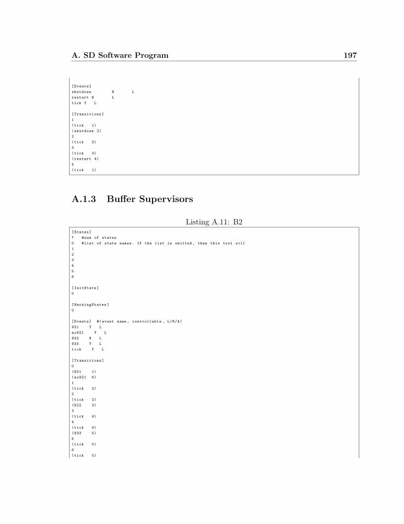
A. SD Software Program 197
[Events]
shutdown N L
restart N L
tick Y L
[Transitions]
1
(tick 1)
(shutdown 2)
2
(tick 3)
3
(tick 3)
(restart 4)
4
(tick 1)
A.1.3 Buffer Supervisors
Listing A.11: B2[States]
7 #num of states
0 #list of state names. If the list is omitted , then this tool will
1
2
3
4
5
6
[InitState]
0
[MarkingStates]
0
[Events] #(event name , controllable , L/R/A)
921 Y L
no921 Y L
922 N L
933 Y L
tick Y L
[Transitions]
0
(921 1)
(no921 6)
1
(tick 2)
2
(tick 2)
(922 3)
3
(tick 4)
4
(tick 4)
(933 5)
5
(tick 0)
6
(tick 0)

198 A. SD Software Program
##################################
Listing A.12: B4[States]
8 #num of states
0 #list of state names. If the list is omitted , then this tool will
1
2
3
5
6
7
8
[InitState]
0
[MarkingStates]
0
[Events] #(event name , controllable , L/R/A)
933 Y L
934 N L
937 Y L
939 Y L
951 Y L
952 N L
953 Y L
954 N L
tick Y L
[Transitions]
0
(933 0)
(952 6)
(934 5)
(954 7)
(tick 0)
1
(tick 1)
(951 8)
(953 8)
2
(tick 2)
(937 8)
3
(tick 3)
(939 8)
5
(tick 1)
6
(tick 2)
7
(tick 3)
8
(tick 0)
##################################
Listing A.13: B6[States]
4 #num of states
0 #list of state names. If the list is omitted , then this tool will
1

A. SD Software Program 199
3
4
[InitState]
0
[MarkingStates]
0
[Events] #(event name , controllable , L/R/A)
937 Y L
938 N L
963 Y L
tick Y L
[Transitions]
0
(937 0)
(938 3)
(tick 0)
1
(963 4)
(tick 1)
3
(tick 1)
4
(tick 0)
##################################
Listing A.14: B7[States]
7 #num of states
0 #list of state names. If the list is omitted , then this tool will
1
2
5
6
7
8
[InitState]
0
[MarkingStates]
0
[Events] #(event name , controllable , L/R/A)
939 Y L
930 N L
965 Y L
971 Y L
973 Y L
974 N L
tick Y L
[Transitions]
0
(939 0)
(930 5)
(973 0)
(974 7)
(tick 0)
1
(971 6)
(tick 1)

200 A. SD Software Program
2
(965 8)
(tick 2)
5
(tick 1)
6
(tick 0)
7
(tick 2)
8
(tick 0)
##################################
Listing A.15: B8[States]
12 #num of states
0 #list of state names. If the list is omitted , then this tool will
1
2
3
4
5
6
7
8
9
10
11
[InitState]
0
[MarkingStates]
0
[Events] #(event name , controllable , L/R/A)
930 N L
971 Y L
972 N L
973 Y L
981 Y L
982 N L
tick Y L
[Transitions]
0
(tick 0)
(930 1)
1
(tick 2)
2
(971 3)
3
(tick 4)
4
(tick 4)
(972 5)
5
(tick 6)
6
(981 7)
7
(tick 8)
8
(tick 8)

A. SD Software Program 201
(982 9)
9
(tick 10)
10
(973 11)
11
(tick 0)
##################################
A.1.4 Additional Supervisors
Listing A.16: AMChooser[States]
14 #num of states
0 #list of state names. If the list is omitted , then this tool will
1
2
3
4
5
6
7
8
9
10
11
12
13
[InitState]
0
[MarkingStates]
0
[Events] #(event name , controllable , L/R/A)
938 N L
963 Y L
965 Y L
974 N L
tick Y L
no963b Y L
no965b Y L
[Transitions]
0
(tick 0)
(no963b 0)
(no965b 0)
(974 1)
(938 2)
1
(no963b 1)
(no965b 1)
(tick 6)
(938 3)
2
(no963b 2)
(no965b 2)
(tick 5)
(974 3)
3

202 A. SD Software Program
(no963b 3)
(no965b 3)
(tick 7)
4
(no963b 4)
(tick 5)
5
(no965b 5)
(tick 5)
(974 9)
(963 11)
6
(no963b 6)
(tick 6)
(965 12)
(938 13)
7
(no963b 7)
(tick 7)
(965 8)
8
(no963b 8)
(tick 5)
9
(no965b 9)
(tick 9)
(963 10)
10
(no965b 10)
(tick 6)
11
(no965b 11)
(974 10)
(tick 0)
12
(no963b 12)
(938 4)
(tick 0)
13
(no963b 13)
(tick 13)
(965 4)
##################################
Listing A.17: B4Path[States]
4 #num of states
0 #list of state names. If the list is omitted , then this tool will
1
2
3
[InitState]
0
[MarkingStates]
0
[Events] #(event name , controllable , L/R/A)
933 Y L
934 N L
937 Y L
939 Y L
tick Y L

A. SD Software Program 203
[Transitions]
0
(tick 0)
(933 0)
(934 2)
1
(tick 1)
(937 3)
(939 3)
2
(tick 1)
3
(tick 0)
##################################
Listing A.18: Force961#generated by pds2hsc
[States]
6 # num of states
0
1
2
3
4
5
[InitState]
0
[MarkingStates]
0
2
[Events]
tick Y L
no963a Y L
no963b Y L
no965a Y L
no965b Y L
961 Y L
963 Y L
964 N L
965 Y L
966 N L
[Transitions]
0
(no965a 0)
(no963a 0)
(961 1)
1
(no965a 1)
(no963a 1)
(tick 2)
2
(no965b 2)
(no963b 2)
(tick 2)
(963 3)
(965 3)
3
(no965b 3)
(no963b 3)
(tick 4)
4

204 A. SD Software Program
(no965a 4)
(no963a 4)
(tick 4)
(964 5)
(966 5)
5
(no965a 5)
(no963a 5)
(tick 0)
Listing A.19: Force963#generated by pds2hsc
[States]
5 # num of states
0
1
2
3
4
[InitState]
0
[MarkingStates]
0
[Events]
tick Y L
no963a Y L
no963b Y L
938 N L
963 Y L
[Transitions]
0
(tick 0)
(938 1)
1
(tick 2)
2
(963 3)
(no963a 4)
(no963b 4)
3
(tick 0)
4
(tick 2)
Listing A.20: Force965#generated by pds2hsc
[States]
5 # num of states
0
1
2
3
4
[InitState]
0
[MarkingStates]
0

A. SD Software Program 205
[Events]
tick Y L
no965a Y L
no965b Y L
974 N L
965 Y L
[Transitions]
0
(tick 0)
(974 1)
1
(tick 2)
2
(no965a 4)
(no965b 4)
(965 3)
3
(tick 0)
4
(tick 2)
Listing A.21: LathePick[States]
8 #num of states
0 #list of state names. If the list is omitted , then this tool will
1
2
3
4
5
6
7
[InitState]
0
[MarkingStates]
0
[Events] #(event name , controllable , L/R/A)
934 N L
951 Y L
953 Y L
tick Y L
[Transitions]
0
(tick 0)
(934 1)
1
(tick 2)
2
(951 3)
3
(tick 4)
4
(tick 4)
(934 5)
5
(tick 6)
6
(953 7)
7

206 A. SD Software Program
(tick 0)
##################################
Listing A.22: TakeB2[States]
8 #num of states
0 #list of state names. If the list is omitted , then this tool will
1
2
3
4
5
6
7
[InitState]
0
[MarkingStates]
0
[Events] #(event name , controllable , L/R/A)
922 N L
930 N L
933 Y L
938 N L
tick Y L
[Transitions]
0
(tick 0)
(922 1)
1
(tick 2)
2
(933 3)
3
(tick 4)
4
(tick 4)
(922 5)
(938 6)
(930 6)
5
(tick 5)
(930 7)
(938 7)
6
(tick 0)
(922 7)
7
(tick 2)
##################################
Listing A.23: TakeB4PutB6[States]
6 #num of states
0 #list of state names. If the list is omitted , then this tool will
1
2
3
4
5
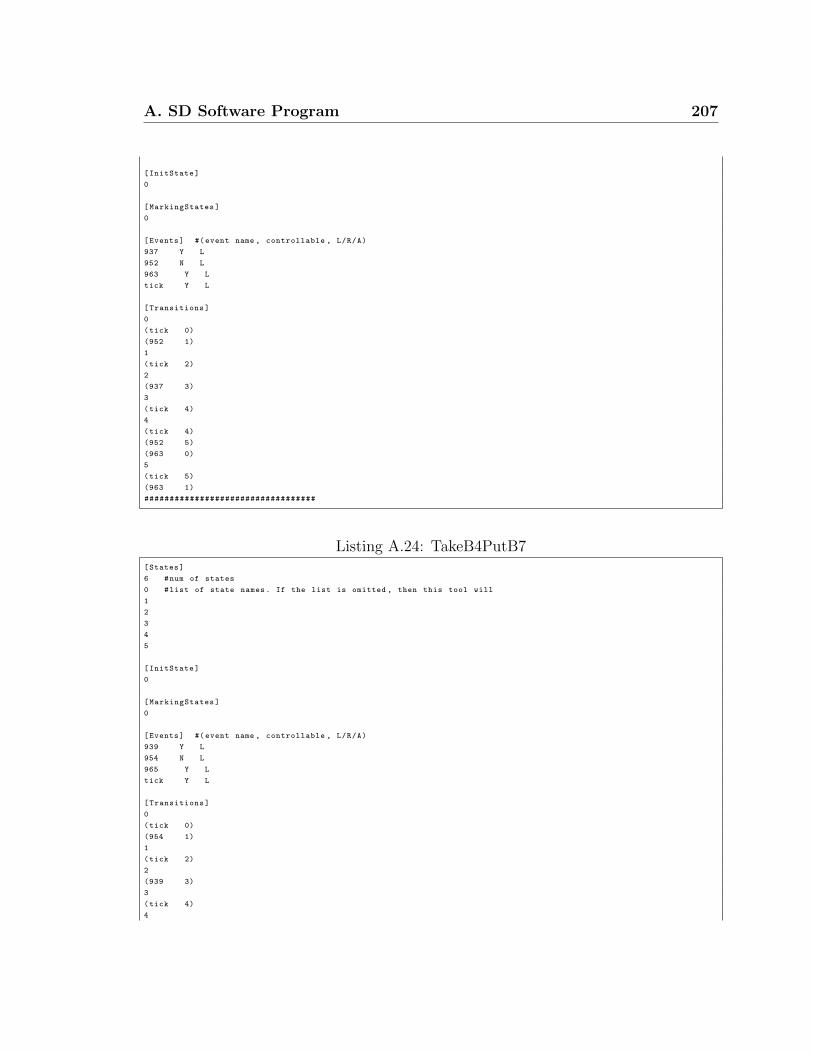
A. SD Software Program 207
[InitState]
0
[MarkingStates]
0
[Events] #(event name , controllable , L/R/A)
937 Y L
952 N L
963 Y L
tick Y L
[Transitions]
0
(tick 0)
(952 1)
1
(tick 2)
2
(937 3)
3
(tick 4)
4
(tick 4)
(952 5)
(963 0)
5
(tick 5)
(963 1)
##################################
Listing A.24: TakeB4PutB7[States]
6 #num of states
0 #list of state names. If the list is omitted , then this tool will
1
2
3
4
5
[InitState]
0
[MarkingStates]
0
[Events] #(event name , controllable , L/R/A)
939 Y L
954 N L
965 Y L
tick Y L
[Transitions]
0
(tick 0)
(954 1)
1
(tick 2)
2
(939 3)
3
(tick 4)
4
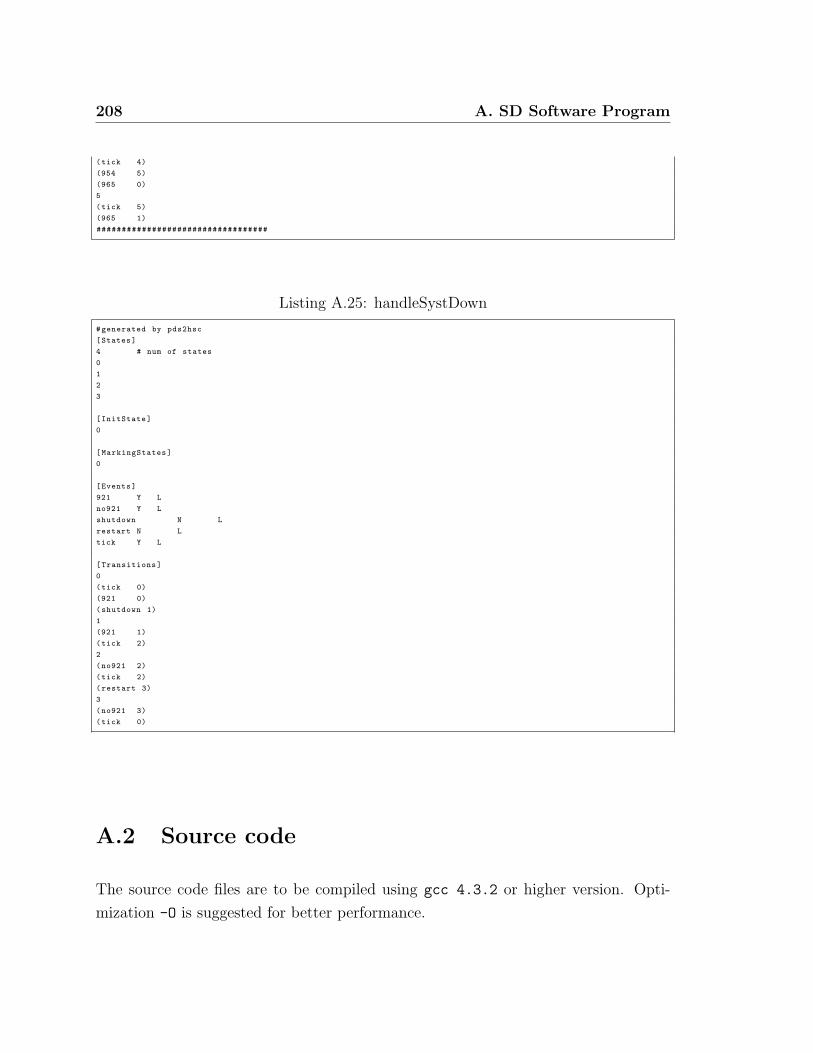
208 A. SD Software Program
(tick 4)
(954 5)
(965 0)
5
(tick 5)
(965 1)
##################################
Listing A.25: handleSystDown
#generated by pds2hsc
[States]
4 # num of states
0
1
2
3
[InitState]
0
[MarkingStates]
0
[Events]
921 Y L
no921 Y L
shutdown N L
restart N L
tick Y L
[Transitions]
0
(tick 0)
(921 0)
(shutdown 1)
1
(921 1)
(tick 2)
2
(no921 2)
(tick 2)
(restart 3)
3
(no921 3)
(tick 0)
A.2 Source code
The source code files are to be compiled using gcc 4.3.2 or higher version. Opti-
mization -O is suggested for better performance.

A. SD Software Program 209
A.2.1 Main
main.cpp
001 002 bool bPrjLoaded = false;
003 char ch = ’\0’;004 char prjfile[MAX PATH];
005 string errmsg;
006 prjfile[0] = ’\0’;007 int iret = 0;
008 char prjoutputfile[MAX PATH];
009
010 char savepath[MAX PATH];
011 savepath[0] = ’\0’;012 HISC SUPERINFO superinfo;
013
014 HISC TRACETYPE tracetype;
015 int computetime = 0;
016
017 while (ch != ’q’ && ch != ’Q’)
018 019 ch = getchoice(bPrjLoaded, prjfile);
020 switch (ch)
021 022 case ’q’:
023 case ’Q’:
024 iret = close prj(errmsg);
025 bPrjLoaded = false;
026 prjfile[0] = ’\0’;027
028 break;
029 //Load a project
030 case ’P’:
031 case ’p’:
032 cout << "Sub name:";

210 A. SD Software Program
033 cin.getline(prjfile, MAX PATH);
034 iret = load prj(prjfile, errmsg);
035 if (iret < 0)
036 037 if (iret > -10000) //error
038 bPrjLoaded = false;
039 else
039 bPrjLoaded = true; //waring
040 041 else
041 bPrjLoaded = true;
042 break;
043 //close the current project
044 case ’c’:
045 case ’C’:
046 iret = close prj(errmsg);
047 bPrjLoaded = false;
048 prjfile[0] = ’\0’;049 break;
050 //File the current project
051 case ’f’:
052 case ’F’:
053 cout << "file name:";054 cin.getline(prjoutputfile, MAX PATH);
055 iret = print prj(prjoutputfile, errmsg);
056 break;
057 //Low Level verification
058 case ’l’:
059 case ’L’:
060 cout << "Show the blocking type(may take long time)(Y/N)?";061 tracetype = (HISC TRACETYPE)getchoice tracetype();
062
063 char verbosechoices[3] = ’0’, ’1’, ’2’;064 cout << "Verbose level (0 - disable, 1 - brief, 2 - full)?";065 const char choice[2] = getkeystroke(verbosechoices,

A. SD Software Program 211
3), ’\0’ ;066 iVerbLevel = atoi(choice);
067
068 computetime = 0;
069
070 superinfo.statesize = -1;
071 superinfo.nodesize = -1;
072 superinfo.time = 0;
073
074 iret = verify low(tracetype, errmsg, &superinfo);
075 cout << "("<< iret << ") ";076
077 if (iret == 0)
078 cout << "This system has been verified succesfully!"079 << endl;
080 if (superinfo.statesize >= 0)
081 cout << "State size of the synchronous product: " <<
082 superinfo.statesize << endl;
083 if (superinfo.nodesize >= 0)
084 cout << "Number of bdd nodes to store" <<
085 " the synchronous product: " << superinfo.nodesize
086 << endl;
087 cout << "Computing time: " << superinfo.time <<
088 " seconds." << endl;
089 computetime += superinfo.time;
090
091 if (iret < 0)
092 093 cout << errmsg << endl;
094 cout << "Press any key to continue...";095 iret = 0;
096 errmsg[0] = ’\0’;097 getkeystroke(NULL, 0);
098 099

212 A. SD Software Program
100 cout << "Total computing time:" << computetime << "
seconds."101 << endl;
102
103 break;
104 105 if (iret < 0)
106 107 cout << errmsg << endl;
108 cout << "Press any key to continue...";109 iret = 0;
110 errmsg[0] = ’\0’;111 getkeystroke(NULL, 0);
112 113 114
115 close hisc();
116
117 return 0;
118 119
120 int getchoice(bool bPrjLoaded, const char ∗prjfile)121 122 char allowed choice[50];
123 int numofchoice = 0;
124
125 cout << endl << endl << endl << endl << endl;
126 cout << "∗∗∗∗∗∗∗∗∗∗∗∗∗∗∗∗∗∗∗∗∗∗∗∗∗∗∗∗∗∗∗∗∗∗∗∗∗∗∗∗∗∗∗∗∗∗∗∗∗" << endl;
127 cout << " Bdd-based HISC Synthesis and Verification Tool " << endl;
128 cout << "∗∗∗∗∗∗∗∗∗∗∗∗∗∗∗∗∗∗∗∗∗∗∗∗∗∗∗∗∗∗∗∗∗∗∗∗∗∗∗∗∗∗∗∗∗∗∗∗∗" << endl;
129 if (!bPrjLoaded)
130 131 allowed choice[0] = ’p’;
132 allowed choice[1] = ’P’;
133 allowed choice[2] = ’q’;

A. SD Software Program 213
134 allowed choice[3] = ’Q’;
135 numofchoice = 4;
136 cout << " P - Load a HISC project " << endl;
137 138 else
138 139 allowed choice[0] = ’c’;
140 allowed choice[1] = ’C’;
141 allowed choice[2] = ’q’;
142 allowed choice[3] = ’Q’;
143 allowed choice[4] = ’F’;
144 allowed choice[5] = ’f’;
145 allowed choice[6] = ’l’;
146 allowed choice[7] = ’L’;
147 numofchoice = 8;
148 cout << " L - Low Level verification " << endl;
149 cout << " F - File the current project " << endl;
150 cout << " C - Close the current project " << endl;
151 152 cout << " Q - Quit " << endl;
153 cout << "∗∗∗∗∗∗∗∗∗∗∗∗∗∗∗∗∗∗∗∗∗∗∗∗∗∗∗∗∗∗∗∗∗∗∗∗∗∗∗∗∗∗∗∗∗∗∗∗∗" << endl;
154 if (bPrjLoaded)
155 156 cout << "Current Project: " << prjfile << endl;
157 158 cout << endl;
159 cout << "Procedure desired:";160 return getkeystroke(allowed choice, numofchoice);
161 162
163 char getkeystroke(char ∗allowed choices, int len)
164 165 char choice;
166 struct termios initial settings, new settings;
167

214 A. SD Software Program
168 tcgetattr(fileno(stdin), &initial settings);
169 new settings = initial settings;
170 new settings.c lflag &= ~ICANON;
171
172 new settings.c cc[VMIN] = 1;
173 new settings.c cc[VTIME] = 0;
174 new settings.c lflag &= ~ISIG;
175
176 tcsetattr(fileno(stdin), TCSANOW, &new settings);
177 if (len > 0)
178 179 do 180 choice = fgetc(stdin);
181 int i;
182 for (i = 0; i < len; i++)
183 184 if (choice == allowed choices[i])
185 break;
186 187 if (i == len)
188 choice = ’\n’;189 while (choice == ’\n’ || choice == ’\r’);190 191 else
191 choice = fgetc(stdin);
192
193 tcsetattr(fileno(stdin),TCSANOW, &initial settings);
194 cout << endl;
195 return choice;
196 197
198 int getchoice savesup()
199 200 char allowed choice[50];
201 int numofchoice = 0;

A. SD Software Program 215
202 char choice;
203
204 allowed choice[0] = ’0’;
205 allowed choice[1] = ’1’;
206 allowed choice[2] = ’2’;
207 allowed choice[3] = ’3’;
208 numofchoice = 4;
209 choice = getkeystroke(allowed choice, numofchoice);
210 return choice - ’0’;
211 212
213 int getchoice tracetype()
214 215 char allowed choice[50];
216 int numofchoice = 0;
217 char choice;
218
219 allowed choice[0] = ’Y’;
220 allowed choice[1] = ’y’;
221 allowed choice[2] = ’N’;
222 allowed choice[3] = ’n’;
223 numofchoice = 4;
224 choice = getkeystroke(allowed choice, numofchoice);
225
226 if (choice == ’Y’ || choice == ’y’)
227 return 1;
228 else
228 return 0;
229 230
231

216 A. SD Software Program
A.2.2 Global Functions, Typedefs, Variables, Preprocessors
symbols
type.h
001
002 const string sTick = "tick";003
004 enum DESTYPE PLANT DES = 0, SPEC DES = 1;005 enum EVENTTYPE CON EVENT = 0, UNCON EVENT = 1;006
007 #define L EVENT 3
008
009 typedef map<string, int> STATES; //state name, index
010 typedef map<int, string> INVSTATES; //state index, name
011
012 typedef map<string, int> EVENTS; //event name, global index
013 typedef map<int, string> INVEVENTS; //event global index, name
014
015 typedef map<string, unsigned short> LOCALEVENTS; //event name,
level-wise index
016 typedef map<unsigned short, string> LOCALINVEVENTS;//event level-wise
index,name
017
018 typedef set<unsigned short> EVENTSET;
019
020 typedef list<int> MARKINGLIST; //link list to save all the marker
states index
021 typedef map<int, int> TRANS; //source state index (key), target state
index
022 #endif // TYPE H
023
024

A. SD Software Program 217
errmsg.h
001
002 #define HISC BAD INTERFACE -11
003 #define HISC TICK NOT FOUND -12
004
005 #define HISC LOWERR GENCONBAD -20
006 #define HISC LOWERR GENP4BAD -21
007 #define HISC LOWERR SUPCP -22
008 #define HISC LOWERR COREACH -23
009 #define HISC LOWERR REACH -24
010 #define HISC LOWERR P5 -25
011 #define HISC LOWERR P6 -26
012 #define HISC LOWERR GENBALEMIBAD -27
013 #define HISC LOWERR ALF -28
014 #define HISC LOWERR PTB -29
015 #define HISC LOWERR SD -30
016 #define HISC LOWERR SDIV -31
017
018 #define HISC VERI LOW UNCON -201
019 #define HISC VERI LOW BLOCKING -202
020 #define HISC VERI LOW P4FAILED -203
021 #define HISC VERI LOW P5FAILED -204
022 #define HISC VERI LOW P6FAILED -205
023 #define HISC VERI LOW CON -206
024 #define HISC VERI LOW ALF -207
025 #define HISC VERI LOW PTB -208
026 #define HISC VERI LOW SD II -209
027 #define HISC VERI LOW SD III 1 -210
028 #define HISC VERI LOW SD III 2 -211
029 #define HISC VERI LOW SD IV -212
030 #define HISC VERI LOW ZERO LB -213
031
032 #define HISC HIGHERR GENCONBAD -30
033 #define HISC HIGHERR GENP3BAD -31
034 #define HISC HIGHERR SUPCP -32

218 A. SD Software Program
035 #define HISC HIGHERR COREACH -33
036 #define HISC HIGHERR REACH -34
037 #define HISC VERI HIGH UNCON -101
038 #define HISC VERI HIGH P3FAILED -102
039 #define HISC VERI HIGH BLOCKING -103
040
041 #define HISC BAD SAVESUPER -97
042 #define HISC BAD PRINT FILE -98
043 #define HISC NOT ENOUGH MEMORY -99
044
045 #define HISC WARN BLOCKEVENTS -10000
046 #define HISC INTERNAL ERR SUBEVENT -10001
047
048 #endif // ERRMSG H
049
050
pubfunc.h
001 extern string str upper(const string &str);
002 extern string str lower(const string &str);
003 extern string str itos(int iInt);
004 extern string str ltos(long long lLong);
005
006 extern string str nocomment(const string & str);
007 extern int scp err(const string & sErr, const int iErrCode);
008
009 extern string GetNameFromFile(const string & vsFile);
010
011 extern int IsInteger(const string &str);
012 extern int CompareInt(const void∗ pa, const void∗ pb);
013
014 extern void bddPrintStats(const bddStat &stat);
015 extern void SetBddPairs(bddPair ∗pPair, const bdd & bddOld, const bdd &
bddNew);

A. SD Software Program 219
016 extern int NumofSharedEvents(const int ∗ pEventsArr a, const int
viNumofEvents a,
017 const int ∗ pEventsArr b, const int viNumofEvents b);
018 extern void my bdd gbchandler(int pre, bddGbcStat ∗s);019
020 #endif // PUBFUNC H
021
022
pubfunc.cpp
001 ∗ PARA: str: a string (input)
002 ∗ RETURN: trimmed string
003 ∗ ∗/004 string str trim(const string &str)
005 006 string sTmp("");
007 unsigned int i = 0;
008
009 //trim off the prefix spaces
010 for (i = 0; i < str.length(); i++)
011 012 if (str[i] != 32 && str[i] != 9)
013 break;
014 015 if (i < str.length())
016 017 sTmp = str.substr(i);
018 019 else
019 020 return sTmp;
021 022
023 //trim off the suffix spaces
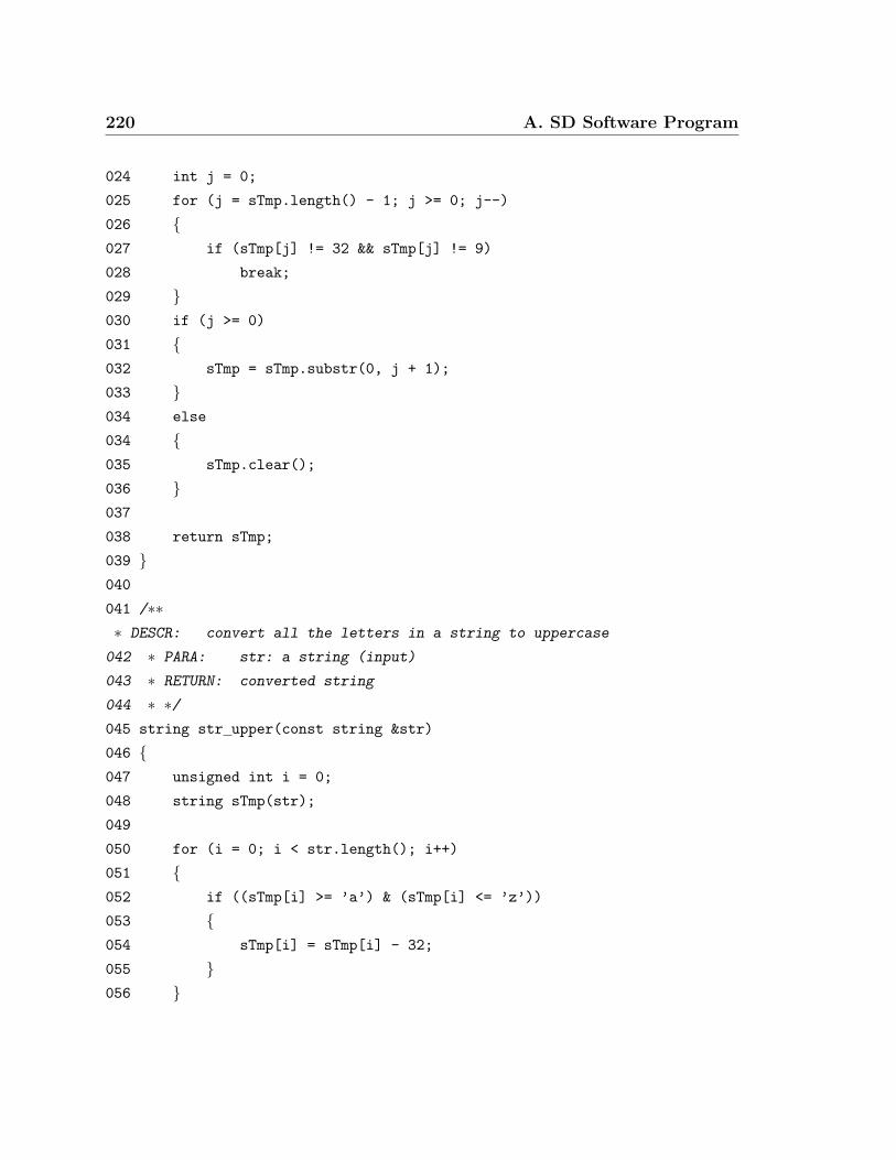
220 A. SD Software Program
024 int j = 0;
025 for (j = sTmp.length() - 1; j >= 0; j--)
026 027 if (sTmp[j] != 32 && sTmp[j] != 9)
028 break;
029 030 if (j >= 0)
031 032 sTmp = sTmp.substr(0, j + 1);
033 034 else
034 035 sTmp.clear();
036 037
038 return sTmp;
039 040
041 /∗∗∗ DESCR: convert all the letters in a string to uppercase
042 ∗ PARA: str: a string (input)
043 ∗ RETURN: converted string
044 ∗ ∗/045 string str upper(const string &str)
046 047 unsigned int i = 0;
048 string sTmp(str);
049
050 for (i = 0; i < str.length(); i++)
051 052 if ((sTmp[i] >= ’a’) & (sTmp[i] <= ’z’))
053 054 sTmp[i] = sTmp[i] - 32;
055 056
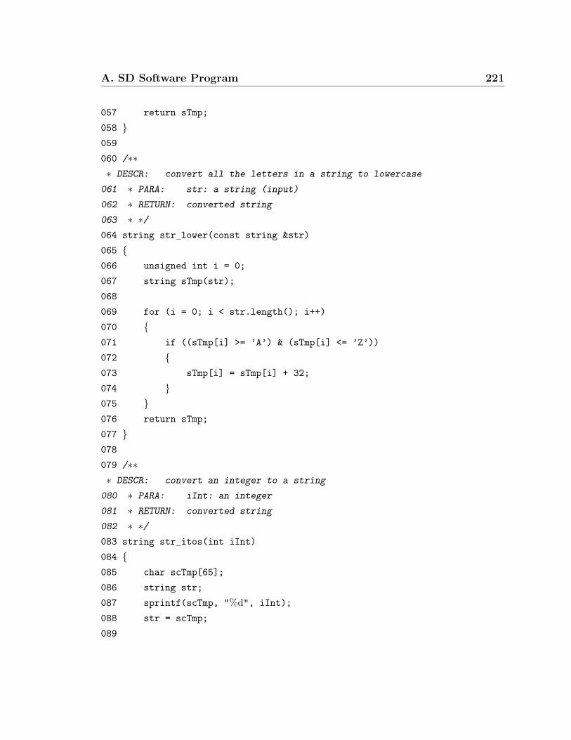
A. SD Software Program 221
057 return sTmp;
058 059
060 /∗∗∗ DESCR: convert all the letters in a string to lowercase
061 ∗ PARA: str: a string (input)
062 ∗ RETURN: converted string
063 ∗ ∗/064 string str lower(const string &str)
065 066 unsigned int i = 0;
067 string sTmp(str);
068
069 for (i = 0; i < str.length(); i++)
070 071 if ((sTmp[i] >= ’A’) & (sTmp[i] <= ’Z’))
072 073 sTmp[i] = sTmp[i] + 32;
074 075 076 return sTmp;
077 078
079 /∗∗∗ DESCR: convert an integer to a string
080 ∗ PARA: iInt: an integer
081 ∗ RETURN: converted string
082 ∗ ∗/083 string str itos(int iInt)
084 085 char scTmp[65];
086 string str;
087 sprintf(scTmp, "%d", iInt);
088 str = scTmp;
089

222 A. SD Software Program
090 return str;
091 092
093 /∗∗∗ DESCR: convert a long integer to a string
094 ∗ PARA: iInt: a long integer
095 ∗ RETURN: converted string
096 ∗ ∗/097 string str ltos(long long lLong)
098 099 char scTmp[65];
100 string str;
101 sprintf(scTmp, "%lld", lLong);
102 str = scTmp;
103
104 return str;
105 106
107 /∗∗∗ DESCR: trim off all the characters after a COMMENT CHAR
108 ∗ PARA: str : a string
109 ∗ RETURN: processed string
110 ∗ ∗/111 string str nocomment(const string & str)
112 113 int i;
114 int iLen = str.length();
115
116 for (i = 0; i < iLen; i++)
117 118 if (str[i] == COMMENT CHAR)
119 break;
120 121 if (i < iLen)
122 return str.substr(0, i);

A. SD Software Program 223
123 else
123 return str;
124 125
126 /∗∗∗ DESCR: Get sub name or des name from a full path file name
127 ∗ with extension ".sub"/".hsc"
128 ∗ ex: vsFile = "/home/roger/m1.sub" will return "m1"
129 ∗ PARA: vsFile: file name with path
130 ∗ RETURN: sub name or des name
131 ∗ ∗/132 string GetNameFromFile(const string & vsFile)
133 134 assert(vsFile.length() > 4);
135 assert(vsFile.substr(vsFile.length() - 4) == ".sub" ||
136 vsFile.substr(vsFile.length() - 4) == ".hsc");137
138 unsigned int iPos = vsFile.find last of(’/’);
139
140 if ( iPos == string::npos)
141 142 return vsFile.substr(0, vsFile.length() - 4);
143 144 else
144 145 return vsFile.substr(iPos + 1, vsFile.length() - 4 - (iPos +
1));
146 147 148
149 /∗∗∗ DESCR: Test if a string could be converted to an integer
150 ∗ PARA: str: a string
151 ∗ RETURN: 0: no 1: yes
152 ∗ ∗/
224 A. SD Software Program
153 int IsInteger(const string &str)
154 155 if (str.length() == 0)
156 return 0;
157 for (unsigned int i = 0; i < str.length(); i++)
158 159 if (str[i] >= ’0’ && str[i] <= ’9’)
160 continue;
161 else
161 return 0;
162 163
164 return 1;
165 166
167 /∗∗∗ DESCR: Compare two integers which are provided by two general
pointers.
168 ∗ qsort, bsearch will use this function
169 ∗ PARA: pa, pb: general pointers pointing to two integers
170 ∗ RETURN: 1: a>b
171 ∗ 0: a=b
172 ∗ -1: a<b
173 ∗ ∗/174 int CompareInt(const void∗ pa, const void∗ pb)
175 176 int a = ∗((int ∗) pa);
177 int b = ∗((int ∗) pb);
178
179 if (a > b)
180 return 1;
181 else if (a < b)
182 return -1;
183 else
183 return 0;

A. SD Software Program 225
184 185
186
187 /∗∗∗ DESCR: To print the content of a bddStat variable.
188 ∗ Original BDD package doesn’t provide such a function.
189 ∗ PARA: bddStat: see documents of Buddy package
190 ∗ RETURN: None
191 ∗ ∗/192 void bddPrintStats(const bddStat &stat)
193 194 cout << endl;
195 cout << "--------------bddStat-----------------" << endl;
196
197 cout << "Num of new produced nodes: " << stat.produced << endl;
198 cout << "Num of allocated nodes: " << stat.nodenum << endl;
199 cout << "Max num of user defined nodes: " << stat.maxnodenum << endl;
200 cout << "Num of free nodes: " << stat.freenodes << endl;
201 cout << "Min num of nodes after garbage collection: " << stat.minfreenodes
202 << endl;
203 cout << "Num of vars:" << stat.varnum << endl;
204 cout << "Num of entries in the internal caches:" << stat.cachesize <<
endl;
205 cout << "Num of garbage collections done until now:" << stat.gbcnum <<
endl;
206 return;
207 208
209 /∗∗∗ DESCR: Set bddpairs based on two bdd variable sets.
210 ∗ The original function bdd setbddpair(...) is not
211 ∗ as the document said.
212 ∗ PARA: pPair: where to add bdd variable pairs
213 ∗ bddOld: variable will be replaced
214 ∗ bddNew: new variable

226 A. SD Software Program
215 ∗ RETURN: None
216 ∗ ∗/217 void SetBddPairs(bddPair ∗pPair, const bdd & bddOld, const bdd &
bddNew)
218 219 assert(pPair != NULL);
220
221 int ∗vOld = NULL;
222 int ∗vNew = NULL;
223 int nOld = 0;
224 int nNew = 0;
225
226 bdd scanset(bddOld, vOld, nOld);
227 bdd scanset(bddNew, vNew, nNew);
228
229 assert(nOld == nNew);
230
231 for (int i = 0; i < nOld; i++)
232 233 bdd setpair(pPair, vOld[i], vNew[i]);
234 235
236 free(vOld);
237 free(vNew);
238
239 return;
240 241
242 /∗∗∗ DESCR: Compute the number of shared events between two DES
243 ∗ PARA: pEventsArr a: Event array for DES a (global index,
sorted)
244 ∗ viNumofEvents a: Number of events in array pEventsArr a
245 ∗ pEventsArr b: Event array for DES b (global index,
sorted)

A. SD Software Program 227
246 ∗ viNumofEvents b: Number of events in array pEventsArr b
247 ∗ RETURN: Number of shared events
248 ∗ ∗/249 int NumofSharedEvents(const int ∗ pEventsArr a, const int
viNumofEvents a,
250 const int ∗ pEventsArr b, const int viNumofEvents b)
251 252 int iNum = 0;
253 int i = 0;
254
255 assert(pEventsArr a != NULL);
256 assert(pEventsArr b != NULL);
257
258 if (viNumofEvents a <= viNumofEvents b)
259 260 for (i = 0; i < viNumofEvents a; i++)
261 262 if (bsearch(&(pEventsArr a[i]), pEventsArr b,
viNumofEvents b,
263 sizeof(int), CompareInt) != NULL)
264 265 iNum++;
266 267 268 269 else
269 270 for (i = 0; i < viNumofEvents b; i++)
271 272 if (bsearch(&(pEventsArr b[i]), pEventsArr a,
viNumofEvents a,
273 sizeof(int), CompareInt) != NULL)
274 275 iNum++;
276
228 A. SD Software Program
277 278 279
280 return iNum;
281 282
283 /∗∗∗ DESCR: Customized Garbage collection handler for this program
284 ∗ PARA: see document of Buddy Package
285 ∗ RETURN: None
286 ∗ ∗/287 void my bdd gbchandler(int pre, bddGbcStat ∗s)288 289 if (!pre)
290 291 if (s->nodes > giNumofBddNodes)
292 293 printf("Garbage collection #294 s-¿num, s-¿nodes,s-¿freenodes);295 printf(” / %.1fs / %.1fs total\n”,296 (float)s-¿time/(float)(CLOCKS PER SEC),297 (float)s-¿sumtime/(float)CLOCKS PER SEC);298 giNumofBddNodes = s-¿nodes;299 300 301 return;302 303304
305
BddSd.h
001 int load prj(const char ∗prjfile, std::string & errmsg);
002

A. SD Software Program 229
003 /∗∗004 ∗ DESCR: close opened HISC project
005 ∗ PARA: errmsg: returned errmsg (output)
006 ∗ RETURN: 0: sucess < 0: fail
007 ∗ ∗/008 int close prj(std::string & errmsg);
009
010 /∗∗011 ∗ DESCR: Save the project in the memory to a text file, just for
verifying
012 ∗ the loaded project.
013 ∗ PARA: filename: where to save the text file (input)
014 ∗ errmsg: returned errmsg (output)
015 ∗ RETURN: 0: sucess < 0: fail
016 ∗ ∗/017 int print prj(std::string filename, std::string & errmsg);
018
019 /∗∗020 ∗ A structure for storing computing result information
021 ∗ ∗/022 typedef struct Hisc SuperInfo
023 024 double statesize; /∗state size∗/025 int nodesize; /∗bdd node size∗/026 int time; /∗computing time (seconds)∗/027 HISC SUPERINFO;
028
029 /∗∗030 ∗ To show a path from the initial state to one bad state or not
031 ∗ Currently HISC SHOW TRACE is only for telling if a blocking state is
032 ∗ deadlock or livelock
033 ∗ ∗/034 enum HISC TRACETYPE HISC NO TRACE = 0, HISC SHOW TRACE = 1;035
036 /∗∗

230 A. SD Software Program
037 ∗ To synthesize on reachable statespace or not
038 ∗ ∗/039 enum HISC COMPUTEMETHODHISC ONCOREACHABLE = 0, HISC ONREACHABLE = 1;040
041 /∗∗042 ∗ DESCR: verify low level
043 ∗ PARA: showtrace: show a trace to the bad state (not implemented)
(input)
044 ∗ subname: low level name ("all" means all the low levels)
(input)
045 ∗ errmsg: returned errmsg (output)
046 ∗ pinfo: returned system infomation (output)
047 ∗ pnextlow: next low level sub index(initially,it must be 0,
mainly
048 ∗ used for "all") (input)
049 ∗ saveproduct: whether to save syn-product (input)
050 ∗ savepath: where to save syn-product (input)
051 ∗ RETURN: 0: successsful < 0: error happened (See errmsg.h)
052 ∗ ∗/053 int verify low(
054 HISC TRACETYPE showtrace,
055 std::string & errmsg,
056 HISC SUPERINFO ∗pinfo);057
058 #endif
059
060
061
BddSd.cpp
001 ∗ errmsg: returned errmsg (output)
002 ∗ RETURN: 0: sucess < 0: fail
003 ∗ ∗/004 int load prj(const char ∗prjfile, string & errmsg)

A. SD Software Program 231
005 006 int iRet = 0;
007
008 assert(prjfile != NULL);
009
010 pSub = new CLowSub(prjfile);
011
012 iRet = pSub->LoadSub();
013
014 errmsg = pSub->GetErrMsg();
015 if (pSub->GetErrCode() < 0)
016 017 if (pSub->GetErrCode() > HISC WARN BLOCKEVENTS) //error
happened
018 019 delete pSub;
020 pSub = NULL;
021 022 //else only a warning
023 024 return iRet;
025 026
027 /∗∗028 ∗ DESCR: close opened HISC project
029 ∗ PARA: errmsg: returned errmsg (output)
030 ∗ RETURN: 0: sucess < 0: fail
031 ∗ ∗/032 int close prj(string & errmsg)
033 034 int iRet = 0;
035
036 if (NULL != pSub)
037 038 errmsg = pSub->GetErrMsg();

232 A. SD Software Program
039 iRet = pSub->GetErrCode();
040 if (pSub->GetErrCode() < 0)
041 042 delete pSub;
043 pSub = NULL;
044 045 046 return iRet;
047 048
049 /∗∗050 ∗ DESCR: clear the HISC enviorment
051 ∗ PARA: none
052 ∗ RETURN: 0
053 ∗ ∗/054 int close hisc()
055 056 if (pSub != NULL)
057 058 delete pSub;
059 pSub = NULL;
060 061 return 0;
062 063
064 /∗∗065 ∗ DESCR: Save the project in the memory to a text file, just for
verifying
066 ∗ the loaded project.
067 ∗ PARA: filename: where to save the text file (input)
068 ∗ errmsg: returned errmsg (output)
069 ∗ RETURN: 0: sucess < 0: fail
070 ∗ ∗/071 int print prj(string filename, string & errmsg)
072
A. SD Software Program 233
073 int iRet = 0;
074 assert(!filename.empty());
075 assert(!errmsg.empty());
076
077 ofstream fout;
078 try
079 080 fout.open(filename.data());
081 if (!fout)
082 throw -1;
083
084 if (pSub->PrintSubAll(fout) < 0)
085 throw -1;
086 fout.close();
087 088 catch(...)
089 090 if (fout.is open())
091 fout.close();
092 pSub->SetErr(filename + ":Unable to create the print file.",093 HISC BAD PRINT FILE);
094 return -1;
095 096
097 return 0;
098
099 errmsg = pSub->GetErrMsg();
100
101 iRet = pSub->GetErrCode();
102
103 pSub->ClearErr();
104
105 return iRet;
106 107

234 A. SD Software Program
108 /∗∗109 ∗ DESCR: verify low level
110 ∗ PARA: showtrace: show a trace to the bad state (not implemented)
(input)
111 ∗ subname: low level name ("all" means all the low levels)
(input)
112 ∗ errmsg: returned errmsg (output)
113 ∗ pinfo: returned system infomation (output)
114 ∗ pnextlow: next low level sub index(initially,it must be 0,
mainly
115 ∗ used for "all") (input)
116 ∗ saveproduct: whether to save syn-product (input)
117 ∗ savepath: where to save syn-product (input)
118 ∗ RETURN: 0: successsful < 0: error happened (See errmsg.h)
119 ∗ ∗/120 int verify low(
121 HISC TRACETYPE showtrace,
122 string & errmsg,
123 HISC SUPERINFO ∗pinfo)124 125 assert(pinfo != NULL);
126
127 int iRet = 0;
128
129 time t tstart;
130 time(&tstart);
131
132 if (pSub->VeriSub(showtrace, ∗pinfo) < 0)
133 134 errmsg = pSub->GetErrMsg();
135 iRet = pSub->GetErrCode();
136 pSub->ClearErr();
137 138
139 time t tend;

A. SD Software Program 235
140 time(&tend);
141 pinfo->time = tend - tstart;
142
143 return iRet;
144 145
146
A.2.3 DES Class
DES.h
001 virtual ~CDES();
002
003 public:
004 int LoadDES();
005 int PrintDES(ofstream & fout);
006
007 public:
008 string GetDESName() const return m sDESName;;009 int ∗ GetEventsArr() return m piEventsArr;;010 int GetNumofEvents() const return m DESEventsMap.size();;011 int GetNumofMarkingStates() const return m MarkingList.size();;012 MARKINGLIST & GetMarkingList() return m MarkingList;;013 int GetNumofStates() const return m iNumofStates;;014 int GetInitState() const return m iInitState;;015 map<int, int> ∗GetTrans() const return m pTransArr;;016 DESTYPE GetDESType() const return m DESType;;017 CSub∗ GetSub() return m pSub;;018 string GetStateName(int iState) return m InvStatesMap[iState];;019
020 EVENTS m DESEventsMap; //A STL Map for events (event name (key),
021 //local event index). Used only for current
DES
022 //(speed reason)
023
236 A. SD Software Program
024 private: //data memeber
025 string m sDESFile; //DES file name with path
026 string m sDESName; //DES name without path and file extension
027 DESTYPE m DESType; //DES type
028
029 int m iNumofStates; //Number of States
030 int m iInitState; //Initial state
031
032 MARKINGLIST m MarkingList; //Link list containing all marking
states
033
034 STATES m StatesMap; //A STL Map for states (state name (key), state
index)
035 INVSTATES m InvStatesMap; //A STL Map for states (state index
(key),
036 //state name)(for printing)
037
038 INVEVENTS m InvDESEventsMap; //A STL Map for events (localindex
(key),
039 //event name). Used only for current
DES
040 //(for printing)
041 EVENTS m UnusedEvents; //A STL Map for blocked events(name: key,
index)
042
043 int ∗m piEventsArr; //Save all the event indices ascendingly.
044 //used for find shared events between two
DESes.
045
046 TRANS ∗m pTransArr; //Transiton Map array, indexed by event
indices.
047 //TRANSMAP: first int: source state index
048 // second int: target state index
049 CSub ∗m pSub; //which subsystem this DES belongs to
050 private: //internal function members

A. SD Software Program 237
051 int AddEvent(const string & vsEventName,
052 const char cControllable);
053 int AddTrans(const string & vsLine,
054 const string & vsExitState,
055 const int viExitState);
056 ;057
058 #endif // DES H
059
060
DES.cpp
001 ∗ vsDESFile: DES file name with path (input)
002 ∗ vDESType: DES Type (inpute)
003 ∗ RETURN: none
004 ∗ ACCESS: public
004 ∗/005 CDES::CDES(CSub ∗vpSub, const string &vsDESFile, const DESTYPE
vDESType)
006 007 m pSub = vpSub;
008 m sDESFile = vsDESFile;
009 m sDESName.clear();
010 m DESType = vDESType;
011 m iNumofStates = 0;
012 m iInitState = -1;
013
014 m MarkingList.clear();
015 m StatesMap.clear();
016 m InvStatesMap.clear();
017 m DESEventsMap.clear();
018 m UnusedEvents.clear();
019 m InvDESEventsMap.clear();
020

238 A. SD Software Program
021 m piEventsArr = NULL;
022 m pTransArr = NULL;
023 024
025 /∗∗∗ DESCR: Destructor
026 ∗ PARA: None
027 ∗ RETURN: None
028 ∗ ACCESS: public
029 ∗/030 CDES::~CDES()
031 032 delete[] m pTransArr;
033 m pTransArr = NULL;
034
035 delete[] m piEventsArr;
036 m piEventsArr = NULL;
037 038
039 /∗∗∗ DESCR: Loading DES file
040 ∗ PARA: None
041 ∗ RETURN: 0: sucess -1: fail
042 ∗ ACCESS: public
043 ∗/044 int CDES::LoadDES()
045 046 ifstream fin;
047 int iRet = 0;
048 string sErr;
049
050 int i = 0;
051
052 string sSubName = m pSub->GetSubName();
053

A. SD Software Program 239
054 try
054 055 m sDESFile = str trim(m sDESFile);
056
057 if (m sDESFile.length() <= 4)
058 059 pSub->SetErr(sSubName + ": Invalid DES file name " +
m sDESFile,
060 HISC BAD DES FILE);
061 throw -1;
062 063
064 if (m sDESFile.substr(m sDESFile.length() - 4) != ".hsc")065 066 pSub->SetErr(sSubName + ": Invalid DES file name " +
m sDESFile,
067 HISC BAD DES FILE);
068 throw -1;
069 070
071 fin.open(m sDESFile.data(), ios::in);
072
073 //unable to find DES file
074 if (!fin)
075 076 pSub->SetErr(sSubName + ": Unable to open the DES file " +
077 m sDESFile, HISC BAD DES FILE);
078 throw -1;
079 080
081 m sDESName = GetNameFromFile(m sDESFile);
082
083 string sDESLoc = sSubName + ":" + m sDESName + " : ";084 char scBuf[MAX LINE LENGTH];
085 string sLine;

240 A. SD Software Program
086 int iField = -1; //0: States 1: InitState 2: MarkingStates
087 //3: Events 4: Transitions
088 char ∗scFieldArr[] = "STATES", "INITSTATE","MARKINGSTATES",089 "EVENTS", "TRANSITIONS";090 int iStatesFieldFlag = 0; //1: just finised reading the
[States] line,
091 // so next line should be the num
of states
092 //0: otherwise
093 int iTmpStateIndex = 0;
094 int iTmpEventIndex = 0;
095 char cEventSub = ’\0’;096 char cControllable = ’\0’;097
098 string sExitState;
099 int iExitState = -1;
100
101 while (fin.getline(scBuf, MAX LINE LENGTH))
102 103 sLine = str nocomment(scBuf);
104 sLine = str trim(sLine);
105
106 if (sLine.empty())
107 continue;
108
109 //Field line
110 if (sLine[0] == ’[’ && sLine[sLine.length() - 1] == ’]’)
111 112 sLine = sLine.substr(1, sLine.length() - 1);
113 sLine = sLine.substr(0, sLine.length() - 1);
114 sLine = str upper(str trim(sLine));
115
116 iField++;
117

A. SD Software Program 241
118 if (iField <= 4)
119 120 if (sLine != scFieldArr[iField])
121 122 pSub->SetErr(sDESLoc +
123 "Field name or order is incorrect!",124 HISC BAD DES FORMAT);
125 throw -1;
126 127 if (iField == 0)
128 129 iStatesFieldFlag = 1;
130 131 132 else
132 133 pSub->SetErr(sDESLoc + "Two many fields.",134 HISC BAD DES FORMAT);
135 throw -1;
136 137 138 else //Data line
139 140 switch (iField)
141 142 case 0: //States
143 if (iStatesFieldFlag == 1) //num of states
144 145 if (atoi(sLine.data()) <= 0 ||
146 atoi(sLine.data()) >
MAX STATES IN ONE COMPONENT DES)
147 148 pSub->SetErr(sDESLoc + "Too few or too manystates",149 HISC BAD DES FORMAT);
242 A. SD Software Program
150 throw -1;
151 152
153 //initialize the number of states
154 m iNumofStates = atoi(sLine.data());
155
156 //initialize the transition arrary
157 m pTransArr = new TRANS[m iNumofStates];
158
159 iStatesFieldFlag = 0;
160 161 else
161 162 if (m StatesMap.find(sLine) !=
m StatesMap.end())
163 164 pSub->SetErr(sDESLoc + "Duplicate statenames--" +
165 sLine,
HISC BAD DES FORMAT);
166 throw -1;
167 168 else if (sLine[0] == ’(’)
169 170 pSub->SetErr(sDESLoc +
171 "The first letter of state names can not be (",172 HISC BAD DES FORMAT);
173 throw -1;
174 175 else
175 176 m StatesMap[sLine] = m StatesMap.size() -
1;
177 m InvStatesMap[m StatesMap.size() - 1] =
sLine;

A. SD Software Program 243
178 179 180
181 break;
182 case 1: //InitState
183
184
//--------------------------------------------------
185 //Must specify the number of states
186 if (m iNumofStates == 0)
187 188 pSub->SetErr(sDESLoc + "Number of states isabsent.",189 HISC BAD DES FORMAT);
190 throw -1;
191 192
193 //If there is no state names specified, generate
state
194 //names automatically.
195 if (m StatesMap.size() == 0)
196 197 for (i = 0; i < m iNumofStates; i++)
198 199 m StatesMap[str itos(i)] = i;
200 m InvStatesMap[i] = str itos(i);
201 202 203
204 //if specify state names, the number of state names
must be
205 //equal to m iNumofStates.
206 if (((unsigned int)m iNumofStates) !=
m StatesMap.size())
207
244 A. SD Software Program
208 pSub->SetErr(sDESLoc + "States are incomplete.",209 HISC BAD DES FORMAT);
210 throw -1;
211 212
213
//--------------------------------------------------------
214
215 //Initial state name must be valid
216 if (m StatesMap.find(sLine) == m StatesMap.end())
217 218 pSub->SetErr(sDESLoc + "Initial state is notdefined.",219 HISC BAD DES FORMAT);
220 throw -1;
221 222
223 //only one initial state allowed
224 if (m iInitState != -1)
225 226 pSub->SetErr(sDESLoc + "More than one initialstates.",227 HISC BAD DES FORMAT);
228 throw -1;
229 230
231 m iInitState = m StatesMap[sLine];
232
233 break;
234 case 2: //MarkingStates
235
236 if (m StatesMap.find(sLine) == m StatesMap.end())
237 238 pSub->SetErr(sDESLoc + "Marking states do notexist.",

A. SD Software Program 245
239 HISC BAD DES FORMAT);
240 throw -1;
241 242
243 iTmpStateIndex = m StatesMap[sLine];
244
245 for (MARKINGLIST::const iterator ci =
m MarkingList.begin();
246 ci != m MarkingList.end(); ci++)
247 248 if (∗ci == iTmpStateIndex)
249 250 pSub->SetErr(sDESLoc + "Duplicate markingstates.",251 HISC BAD DES FORMAT);
252 throw -1;
253 254 255
256 m MarkingList.push back(iTmpStateIndex);
257
258 break;
259 case 3: //Events
260
261 //Get event type H/R/A/L
262 if (sLine.length() < 5)
263 264 pSub->SetErr(sDESLoc + "Incorrect event definition.",265 HISC BAD DES FORMAT);
266 throw -1;
267 268 cEventSub = sLine[sLine.length() - 1];
269 sLine = str trim(sLine.substr(0, sLine.length() -
1));
270

246 A. SD Software Program
271 //Get controllable or not
272 if (sLine.length() < 3)
273 274 pSub->SetErr(sDESLoc + "Incorrect event definition.",275 HISC BAD DES FORMAT);
276 throw -1;
277 278 cControllable = sLine[sLine.length() - 1];
279 sLine = str trim(sLine.substr(0, sLine.length() -
1));
280
281 //Get event name
282 if (sLine.empty())
283 284 pSub->SetErr(sDESLoc + "Incorrect event definition.",285 HISC BAD DES FORMAT);
286 throw -1;
287 288
289 if (cEventSub >= ’a’)
290 cEventSub -= 32;
291 if (cControllable >= ’a’)
292 cControllable -= 32;
293
294 iTmpEventIndex = AddEvent(sLine, cControllable);
295 if (iTmpEventIndex < 0)
296 throw -1; //Errmsg generated by AddEvent
297
298 m DESEventsMap[sLine] = iTmpEventIndex;
299 m UnusedEvents[sLine] = iTmpEventIndex;
300 m InvDESEventsMap[iTmpEventIndex] = sLine;
301 break;
302
303 case 4: //Transitions
304 //check exiting state

A. SD Software Program 247
305 if (sLine[0] != ’(’)
306 307 if (m StatesMap.find(sLine) ==
m StatesMap.end())
308 309 pSub->SetErr(sDESLoc + "Exiting state:" +
sLine +
310 " in transitions does not exist",311 HISC BAD DES FORMAT);
312 throw -1;
313 314 iExitState = m StatesMap[sLine];
315 sExitState = sLine;
316 317 else //Transitions
318 319 if (AddTrans(sLine, sExitState, iExitState) <
0)
320 throw -1;
321 322 break;
323 default:
324 pSub->SetErr(sDESLoc + "Bad DES file format!",325 HISC BAD DES FORMAT);
326 throw -1;
327 328 329 330
331 //No initial state defined
332 if (m iInitState == -1)
333 334 pSub->SetErr(sDESLoc + "No initial state.",HISC BAD DES FORMAT);
335 throw -1;

248 A. SD Software Program
336 337 //No marking states defined
338 if (m MarkingList.size() == 0)
339 340 pSub->SetErr(sDESLoc + "No marking states",HISC BAD DES FORMAT);
341 throw -1;
342 343 //must have all the fields
344 if (iField != 4)
345 346 pSub->SetErr(sDESLoc + "Incomplete DES file.",HISC BAD DES FORMAT);
347 throw -1;
348 349
350 //Add event indices into m piEventsArr;
351 m piEventsArr = new int[m DESEventsMap.size()];
352 i = 0;
353 for (EVENTS::const iterator ci = m DESEventsMap.begin();
354 ci != m DESEventsMap.end(); ++ci)
355 356 m piEventsArr[i] = ci->second;
357 ++i;
358 359 qsort(m piEventsArr, m DESEventsMap.size(), sizeof(int),
CompareInt);
360
361 //unused events
362 if (m UnusedEvents.size() > 0)
363 364 string sWarn;
365 sWarn = "\nWarning: ";366 sWarn += "Unused events are disabled at every state of DES " +
sDESLoc + "\n";

A. SD Software Program 249
367 for (EVENTS::const iterator ci = m UnusedEvents.begin();
368 ci != m UnusedEvents.end(); ++ci)
369 370 sWarn += ci->first;
371 sWarn += "\n";372 373 pSub->SetErr(sWarn, HISC WARN BLOCKEVENTS);
374 375
376 fin.close();
377 378 catch (int iError)
379 380 if (fin.is open())
381 fin.close();
382 iRet = iError;
383 384 return iRet;
385 386
387 /∗388 ∗ DESCR: Add an event to CSub event map and CProject event map
389 ∗ For CSub event map: If exists, return local index;
390 ∗ Otherwise create a new one.
391 ∗ For CProject event map: If exists, must have same global
index;
392 ∗ Otherwise the event sets are not
disjoint
393 ∗ PARA: vsEventName: Event name(input)
394 ∗ cEventSub: Event type (’H", ’L’, ’R’, ’A’)(input)
395 ∗ cControllable: Controllable? (’Y’, ’N’)(input)
396 ∗ RETURN: >0 global event index
397 ∗ <0 the event sets are not disjoint.
398 ∗ ACCESS: Private
399 ∗/

250 A. SD Software Program
400 int CDES::AddEvent(const string & vsEventName, const char
cControllable)
401 402 string sErr;
403
404 int iTmpEventIndex = 0;
405 int iTmpLocalEventIndex = 0;
406
407 string sDESLoc = m pSub->GetSubName() + ": " + m sDESName + ": ";408
409 //Controllable or uncontrollable
410 if (cControllable != ’Y’ && cControllable != ’N’)
411 412 pSub->SetErr(sDESLoc + "Unknown event controllable type--"+vsEventName,
413 HISC BAD DES FORMAT);
414 return -1;
415 416
417 //already defined in current DES
418 if (m DESEventsMap.find(vsEventName) != m DESEventsMap.end())
419 420 pSub->SetErr(sDESLoc + "Duplicate events definition--" + vsEventName,
421 HISC BAD DES FORMAT);
422 return -1;
423 424
425 //Compute local event index
426 iTmpLocalEventIndex = m pSub->AddSubEvent(vsEventName,
427 (cControllable == ’Y’)? CON EVENT:UNCON EVENT);
428
429 if ((cControllable == ’Y’ && iTmpLocalEventIndex % 2 == 0) ||
430 (cControllable == ’N’ && iTmpLocalEventIndex % 2 == 1))
431 432 pSub->SetErr(sDESLoc + "Event " + vsEventName +

A. SD Software Program 251
433 " has inconsistent controllability definitions.",434 HISC BAD DES FORMAT);
435 return -1;
436 437 //Compute global event index
438 iTmpEventIndex = pSub->GenEventIndex(iTmpLocalEventIndex);
439
440 //Add Event to pSub->m AllEventsMap
441 if (pSub->AddPrjEvent(vsEventName, iTmpEventIndex) < 0)
442 443 sErr = "Event conflict--" + m pSub->GetSubName() + ":" +
444 this->GetDESName() + ":" +
445 vsEventName + " is also defined in sub " + " event";446 pSub->SetErr(sErr, HISC BAD DES FORMAT);
447 iTmpEventIndex = -1;
448 449
450 return iTmpEventIndex;
451 452
453 /∗454 ∗ DESCR: Add a transition to the m pTransArr of the current DES.
455 ∗ PARA: vsLine: a text line in [Transition] field(input)
456 ∗ vsExitState: source state name of the transition(input)
457 ∗ viExitState: source state index of the transition(input)
458 ∗ RETURN: 0: success -1: fail
459 ∗ ACCESS: private
460 ∗/461 int CDES::AddTrans(const string & vsLine,
462 const string & vsExitState,
463 const int viExitState)
464 465 string sTrans = vsLine;
466
467 string sEnterState;
252 A. SD Software Program
468 int iEnterStateIndex;
469
470 string sTransEvent;
471 int iTransEventIndex;
472
473 unsigned long iSepLoc = string::npos;
474 string sErrMsg;
475
476 string sDESLoc = m pSub->GetSubName() + ": " + m sDESName + ": ";477
478
479 try
479 480 if (viExitState == -1)
481 482 pSub->SetErr(sDESLoc + "No existing state for transitions",483 HISC BAD DES FORMAT);
484 throw -1;
485 486
487 //remove ’(’ and ’)’
488 sTrans = sTrans.substr(1);
489 sTrans = sTrans.substr(0, sTrans.length() - 1);
490 sTrans = str trim(sTrans);
491
492 //find sepration character ’\t’ or ’ ’
493 iSepLoc = sTrans.find last of(’\t’);494 if (iSepLoc == string::npos)
495 iSepLoc = sTrans.find last of(’ ’);
496
497 if (iSepLoc == string::npos)
498 499 pSub->SetErr(sDESLoc +
500 "No event or entering state for transition. (" +
501 sTrans + ")", HISC BAD DES FORMAT);

A. SD Software Program 253
502 throw -1;
503 504 else
504 505 sEnterState = str trim(sTrans.substr(iSepLoc + 1));
506 sTransEvent = str trim(sTrans.substr(0, iSepLoc));
507 508
509 //Check event in transitions
510 if (m DESEventsMap.find(sTransEvent) == m DESEventsMap.end())
511 512 pSub->SetErr(sDESLoc + "Event " + sTransEvent +
513 " in transitions does not exist.",514 HISC BAD DES FORMAT);
515 throw -1;
516 517 iTransEventIndex = m DESEventsMap[sTransEvent];
518 m UnusedEvents.erase(sTransEvent);
519
520 //Check entering state
521 if (m StatesMap.find(sEnterState) == m StatesMap.end())
522 523 pSub->SetErr(sDESLoc + "State " + sEnterState +
524 " in transitions does not exist.",525 HISC BAD DES FORMAT);
526 throw -1;
527 528 iEnterStateIndex = m StatesMap[sEnterState];
529
530 //Check determinacy
531 if (m pTransArr[viExitState].find(iTransEventIndex) !=
532 m pTransArr[viExitState].end())
533 534 pSub->SetErr(sDESLoc + "ExitState:" + vsExitState +
535 " has nondeterministic transitions on event " +
254 A. SD Software Program
sTransEvent,
536 HISC BAD DES FORMAT);
537 throw -1;
538 539 m pTransArr[viExitState][iTransEventIndex] = iEnterStateIndex;
540 541 catch(int)
542 543 return -1;
544 545
546 return 0;
547 548
549 /∗550 ∗ DESCR: Print this DES in memory to a file (for checking)
551 ∗ PARA: fout: file stream(input)
552 ∗ RETURN: 0: success -1: fail
553 ∗ ACCESS: public
554 ∗/555 int CDES::PrintDES(ofstream & fout)
556 557 try
557 558 int i = 0;
559
560 fout << endl << "#——-DES: " << m sDESName << " ---------" <<
endl;
561 fout << "[States]" << endl;
562 fout << m iNumofStates << endl;
563
564 for (INVSTATES::const iterator ci = m InvStatesMap.begin();
565 ci != m InvStatesMap.end(); ++ci)
566 567 fout << ci->second << endl;

A. SD Software Program 255
568 569
570 fout << endl;
571 fout << "[InitState]" << endl;
572 fout << m InvStatesMap[m iInitState] << endl;
573
574 fout << endl;
575 fout << "[MarkingStates]" << endl;
576 for (MARKINGLIST::const iterator ci = m MarkingList.begin();
577 ci != m MarkingList.end(); ++ci)
578 579 fout << m InvStatesMap[∗ci] << endl;
580 581
582 fout << endl;
583 fout << "[Events]" << endl;
584 for (INVEVENTS::const iterator ci = m InvDESEventsMap.begin();
585 ci != m InvDESEventsMap.end(); ++ci)
586 587 if (ci->first % 2 == 0) //uncontrollable
588 fout << ci->second << "\t" << "N" << "\tL" << endl;
589 else
589 fout << ci->second << "\t" << "Y" << "\tL" << endl;
590 591
592 fout << endl;
593 fout << "[Transitions]" << endl;
594 if (m pTransArr != NULL)
595 596 for (i = 0; i < m iNumofStates; i++)
597 598 fout << m InvStatesMap[i] << endl;
599
600 for (TRANS::const iterator ci =
(m pTransArr[i]).begin();

256 A. SD Software Program
601 ci != (m pTransArr[i]).end(); ++ci)
602 603 fout << "(" << m InvDESEventsMap[ci->first] << " "
604 << m InvStatesMap[ci->second] << ")" << endl;
605 606 607 608
609 fout <<
"################################################"
<< endl;
610 611 catch(...)
612 613 return -1;
614 615 return 0;
616 617
618
A.2.4 Sub Class
Sub.h
001 virtual ~CSub();
002 virtual unsigned short AddSubEvent(const string & vsEventName,
003 const EVENTTYPE vEventType);
004 virtual int PrintSub(ofstream & fout) = 0;
005 virtual int PrintSubAll(ofstream& fout) = 0;
006 virtual string SearchEventName(unsigned short usiLocalIndex) = 0;
007
008 virtual int LoadSub() = 0;
009 virtual int VeriSub(const HISC TRACETYPE showtrace,
010 HISC SUPERINFO & superinfo) = 0;
011

A. SD Software Program 257
012 void SetErr(const string & vsErrMsg, const int viErrCode);
013
014 int GenEventIndex(const unsigned short vusiLocalEventIndex);
015 int SearchPrjEvent(const string & vsEventName);
016 int SearchSubEvent(const string & vsEventName);
017 INVEVENTS & GetInvAllEventsMap() return m InvAllEventsMap;;018
019 string GetErrMsg() const return m sErrMsg;;020 int GetErrCode() const return m iErrCode;;021 void ClearErr();
022
023 int AddPrjEvent(const string & vsEventName, const int
viEventIndex);
024
025 private:
026 string m sErrMsg; //Error msg during processing this project
027 int m iErrCode; //Error code during processing this project
028
029 public: //access methods
030 virtual string GetSubName() const return m sSubName;;031
032 virtual int GetNumofDES() const
032 return m iNumofPlants + m iNumofSpecs;;033 virtual unsigned short GetMaxUnCon()
034 return m usiMaxUnCon;;035 virtual unsigned short GetMaxCon()
036 return m usiMaxCon;;037
038 private: //DES reorder related memebers
039 int ∗∗ m piCrossMatrix;
040 int DESReorder Sift();
041 double TotalCross Sift(double dOldCross, double dSwapCross,
042 int iCur, int iFlag);
043 double cross(int i, int j);
044 int DESReorder Force();

258 A. SD Software Program
045 void UpdatePos();
046 void InsertDES(int iCur, int iPos);
047 double TotalCross Force();
048 double Force(int i);
049 int InitialDESOrder();
050
051 protected: //protected methods
052 virtual string GetDESFileFromSubFile(const string & vsSubFile,
053 const string &vsDES);
054 virtual int MakeBdd() = 0;
055 virtual int InitBddFields();
056 virtual int ClearBddFields();
057
058 int DESReorder();
059
060 int PrintStateSet(const bdd & bddStateSet, int viSetFlag);
061 void PrintStateSet2(const bdd & bddStateSet);
062 bdd GetOneState(const bdd & bddStates);
063 int CountStates(const bdd & bddStateSet);
064
065 int PrintEvents(ofstream & fout);
066 int PrintTextTrans(ofstream & fout, bdd & bddController,
067 unsigned short usiLocalIndex,
068 const bdd & bddReach, string sEventName,
069 STATES & statesMap);
070 bdd SimplifyController(const bdd & bddController, const unsigned
short usiIndex);
071
072 protected: //fields
073 string m sSubFile; //this subsytem file name(".sub") with path.
074 string m sSubName; //This subsystem name
075
076 int m iNumofPlants; //Number of Plant DES
077 int m iNumofSpecs; //Number of Specification DES
078 //(High: all interface DES; Low: 1)

A. SD Software Program 259
079
080 CDES ∗∗m pDESArr; //DES Array for all the DES in high or low
levels.
081 //(High: including all interface DES,
082 //Low: only including 1 DES for this
subsystem)
083
084 EVENTSET m SubPlantEvents;
085 EVENTSET m SubSupervisorEvents;
086
087 LOCALEVENTS m SubEventsMap; //save all the events map in this
subsytems
088 //(name(key), local index(16 bits))
089 //just for compute local event index.
090 LOCALINVEVENTS m InvSubEventsMap;
091
092 EVENTS m AllEventsMap; //The map containing all the events in this
project
093 //(Event Name (key), Event global index)
094 INVEVENTS m InvAllEventsMap; //The map containing all the events in
this
095 //project (Event global index (key),
Event Name)
096
097 unsigned short m usiMaxCon; //Max index of controllable events
(1,3,...)
098 unsigned short m usiMaxUnCon;//Max index of uncontrollable
events(2,4,..)
099
100 /∗BDD needed fields∗/101 int m iNumofBddNormVar; //Num of BDD normal variables in the sub.
102 int ∗m piDESOrderArr; //DES indices organized as clusters.
103 int ∗m piDESPosArr; //DES positions in the m piDESOrderArr
104
105 bdd m bddInit; //Initial state predicate

260 A. SD Software Program
106 bdd m bddMarking; //Marking states predicate
107 bdd m bddSuper; //The generated supervisor
108
109 //////////////////////////////////////////////////////////////////
110 //Transition predicates and its variable sets, variable pairs.
111 //0: High level events
112 //1: Request events
113 //2: Answer events
114 //3: Low level events
115 //////////////////////////////////////////////////////////////////
116 //Transition predicates
117 bdd ∗m pbdd ConTrans;
118 bdd ∗m pbdd ConPlantTrans;
119 bdd ∗m pbdd ConSupTrans;
120 bdd ∗m pbdd UnConTrans;
121 bdd ∗m pbdd UnConPlantTrans;
122 bdd ∗m pbdd UnConSupTrans;
123
124 //variable(DES index) set for transition predicates
125 bdd ∗m pbdd ConVar;
126 bdd ∗m pbdd ConVarPrim;
127 bdd ∗m pbdd UnConVar;
128 bdd ∗m pbdd UnConVarPrim;
129 //plant part variables
130 bdd ∗m pbdd UnConPlantVar;
131 bdd ∗m pbdd UnConPlantVarPrim;
132 bdd ∗m pbdd ConPhysicVar; //for simplifying controller (note:
physical)
133 bdd ∗m pbdd ConPhysicVarPrim;//for simplifying controller
(note:physical)
134 //supervisor part variables
135 bdd ∗m pbdd UnConSupVar;
136 bdd ∗m pbdd UnConSupVarPrim;
137 bdd ∗m pbdd ConSupVar; //for simplifying controller (note:
physical)

A. SD Software Program 261
138 bdd ∗m pbdd ConSupVarPrim;//for simplifying controller
(note:physical)
139 //variable pairs(normal-prime)
140 bddPair ∗∗m pPair Con;
141 bddPair ∗∗m pPair UnCon;
142 bddPair ∗∗m pPair ConPrim;
143 bddPair ∗∗m pPair UnConPrim;
144 ;145 #endif // SUB H
146
147
Sub.cpp
001 ∗/002 CSub::CSub(const string & vsSubFile)
003 004 m AllEventsMap.clear();
005 m InvAllEventsMap.clear();
006
007 m iErrCode = 0;
008 m sErrMsg.clear();
009
010 m sSubFile = vsSubFile;
011 m sSubName.clear();
012
013 m iNumofPlants = -1;
014 m iNumofSpecs = -1;
015
016 m pDESArr = NULL;
017
018 m SubEventsMap.clear();
019
020 m usiMaxCon = 0xFFFF;
021 m usiMaxUnCon = 0x0;

262 A. SD Software Program
022
023 m piDESOrderArr = NULL;
024 m piDESPosArr = NULL;
025
026 InitBddFields();
027 028
029 /∗∗∗ DESCR: Destructor
030 ∗ PARA: None
031 ∗ RETURN: None
032 ∗ ACCESS: public
033 ∗/034 CSub::~CSub()
035 036 if (m pDESArr != NULL)
037 038 int iNumofDES = this->GetNumofDES();
039
040 for (int i = 0; i < iNumofDES; i++)
041 042 if (m pDESArr[i] != NULL)
043 044 delete m pDESArr[i];
045 m pDESArr[i] = NULL;
046 047 048 delete[] m pDESArr;
049 m pDESArr = NULL;
050 051
052
053 delete[] m piDESOrderArr;
054 m piDESOrderArr = NULL;
055 delete[] m piDESPosArr;

A. SD Software Program 263
056 m piDESPosArr = NULL;
057
058 ClearBddFields();
059 060
061 /∗062 ∗ DESCR: Initialize BDD related data members
063 ∗ PARA: None
064 ∗ RETURN: 0
065 ∗ ACCESS: protected
066 ∗/067 int CSub::InitBddFields()
068 069 m iNumofBddNormVar = 0;
070 m bddInit = bddtrue;
071 m bddMarking = bddtrue;
072 m bddSuper = bddfalse;
073
074 m pbdd ConTrans = NULL;
075 m pbdd ConPlantTrans = NULL;
076 m pbdd ConSupTrans = NULL;
077
078 m pbdd UnConTrans = NULL;
079 m pbdd UnConPlantTrans = NULL;
080 m pbdd UnConSupTrans = NULL;
081
082 m pbdd ConVar = NULL;
083 m pbdd ConVarPrim = NULL;
084
085 m pbdd UnConVar = NULL;
086 m pbdd UnConVarPrim = NULL;
087
088 m pbdd UnConPlantVar = NULL;
089 m pbdd UnConPlantVarPrim = NULL;
090

264 A. SD Software Program
091 m pbdd UnConSupVar = NULL;
092 m pbdd UnConSupVarPrim = NULL;
093
094 m pbdd ConPhysicVar = NULL;
095 m pbdd ConPhysicVarPrim = NULL;
096
097 m pbdd ConSupVar = NULL;
098 m pbdd ConSupVarPrim = NULL;
099
100 m pPair Con = NULL;
101 m pPair UnCon = NULL;
102 m pPair ConPrim = NULL;
103 m pPair UnConPrim = NULL;
104
105 return 0;
106 107
108 /∗109 ∗ DESCR: Release memory for BDD related data members
110 ∗ PARA: None
111 ∗ RETURN: 0
112 ∗ ACCESS: protected
113 ∗/114 int CSub::ClearBddFields()
115 116 delete[] m pbdd ConTrans;
117 m pbdd ConTrans = NULL;
118
119 delete[] m pbdd ConPlantTrans;
120 m pbdd ConPlantTrans = NULL;
121
122 delete[] m pbdd ConSupTrans;
123 m pbdd ConSupTrans = NULL;
124
125 delete[] m pbdd UnConTrans;
A. SD Software Program 265
126 m pbdd UnConTrans = NULL;
127
128 delete[] m pbdd UnConPlantTrans;
129 m pbdd UnConPlantTrans = NULL;
130
131 delete[] m pbdd UnConSupTrans;
132 m pbdd UnConSupTrans = NULL;
133
134 delete[] m pbdd ConVar;
135 m pbdd ConVar = NULL;
136 delete[] m pbdd UnConVar;
137 m pbdd UnConVar = NULL;
138
139 delete[] m pbdd ConVarPrim;
140 m pbdd ConVarPrim = NULL;
141 delete[] m pbdd UnConVarPrim;
142 m pbdd UnConVarPrim = NULL;
143
144 delete[] m pbdd UnConPlantVar;
145 m pbdd UnConPlantVar = NULL;
146 delete[] m pbdd UnConPlantVarPrim;
147 m pbdd UnConPlantVarPrim = NULL;
148
149 delete[] m pbdd UnConSupVar;
150 m pbdd UnConSupVar = NULL;
151 delete[] m pbdd UnConSupVarPrim;
152 m pbdd UnConSupVarPrim = NULL;
153
154 delete[] m pbdd ConPhysicVar;
155 m pbdd ConPhysicVar = NULL;
156 delete[] m pbdd ConPhysicVarPrim;
157 m pbdd ConPhysicVarPrim = NULL;
158
159 delete[] m pbdd ConSupVar;
160 m pbdd ConSupVar = NULL;

266 A. SD Software Program
161 delete[] m pbdd ConSupVarPrim;
162 m pbdd ConSupVarPrim = NULL;
163
164 if (m pPair UnCon != NULL)
165 166 for (int i = 0; i < m usiMaxUnCon; i += 2)
167 168 if (m pPair UnCon[i/2] != NULL)
169 170 bdd freepair(m pPair UnCon[i/2]);
171 m pPair UnCon[i/2] = NULL;
172 173 174 delete[] m pPair UnCon;
175 m pPair UnCon = NULL;
176 177
178 if (m pPair Con != NULL)
179 180 for (int i = 1; i < (unsigned short)(m usiMaxCon + 1); i +=
2)
181 182 if (m pPair Con[(i - 1)/2] != NULL)
183 184 bdd freepair(m pPair Con[(i - 1)/2]);
185 m pPair Con[(i - 1)/2] = NULL;
186 187 188 delete[] m pPair Con;
189 m pPair Con = NULL;
190 191
192 if (m pPair UnConPrim != NULL)
193 194 for (int i = 0; i < m usiMaxUnCon; i += 2)

A. SD Software Program 267
195 196 if (m pPair UnConPrim[i/2] != NULL)
197 198 bdd freepair(m pPair UnConPrim[i/2]);
199 m pPair UnConPrim[i/2] = NULL;
200 201 202 delete[] m pPair UnConPrim;
203 m pPair UnConPrim = NULL;
204 205
206 if (m pPair ConPrim != NULL)
207 208 for (int i = 1; i < (unsigned short)(m usiMaxCon + 1); i +=
2)
209 210 if (m pPair ConPrim[(i - 1)/2] != NULL)
211 212 bdd freepair(m pPair ConPrim[(i - 1)/2]);
213 m pPair ConPrim[(i - 1)/2] = NULL;
214 215 216 delete[] m pPair ConPrim;
217 m pPair ConPrim = NULL;
218 219
220 return 0;
221 222
223 /∗224 ∗ DESCR: Generate a DES file name with path (∗.hsc) from a sub file
name
225 ∗ with path (.sub) and a DES file name without path.
226 ∗ ex: vsSubFile = "/home/roger/high.sub", vsDES =
"AttchCase.hsc",

268 A. SD Software Program
227 ∗ will return "/home/roger/AttchCase.hsc"
228 ∗ PARA: vsSubFile: sub file name with path
229 ∗ vsDES: DES file name without path
230 ∗ RETURN: Generated DES file name with path
231 ∗ ACCESS: protected
232 ∗/233 string CSub::GetDESFileFromSubFile(const string & vsSubFile,
234 const string &vsDES)
235 236 assert(vsSubFile.length() > 4);
237 assert(vsSubFile.substr(vsSubFile.length() - 4) == ".sub");238 assert(vsDES.length() > 0);
239 string sDES = vsDES;
240
241 if (sDES.length() > 4)
242 243 if (sDES.substr(sDES.length() - 4) == ".hsc")244 245 sDES = sDES.substr(0, sDES.length() - 4);
246 247 248 sDES += ".hsc";249
250 unsigned int iPos = vsSubFile.find last of(’/’);
251
252 if ( iPos == string::npos)
253 return sDES;
254 else
254 return vsSubFile.substr(0, iPos + 1) + sDES;
255 256
257 /∗∗∗ DESCR: Add events to the event Map of this sub. If the event already
exits,
258 ∗ return its index; Otherwise generate a new 16 bit unsigned

A. SD Software Program 269
index
259 ∗ and return the index.
260 ∗ PARA: vsEventName: Event name
261 ∗ vEventType: Controllable? (CON EVENT, UNCON EVENT)
262 ∗ RETURN: >0: event index (odd: controllable even: uncontrollable)
263 ∗ 0: error
264 ∗ ACCESS: public
265 ∗/266 unsigned short CSub::AddSubEvent(const string & vsEventName,
267 const EVENTTYPE vEventType)
268 269 const char ∗ DEBUG = "CSub::AddSubEvent():";270 PRINT DEBUG << "vsEventName = " << vsEventName << endl;
271
272 LOCALEVENTS::const iterator citer;
273
274 citer = m SubEventsMap.find(vsEventName);
275
276 if (citer != m SubEventsMap.end()) //the event exists, return its
index
277 return citer->second;
278 else //the event does not exist, generate a new index.
279 280 if (vEventType == CON EVENT)
281 282 m usiMaxCon += 2;
283 m SubEventsMap[vsEventName] = m usiMaxCon;
284 m InvSubEventsMap[m usiMaxCon] = vsEventName;
285 #ifdef DEBUG TIME
286 PRINT DEBUG << "vEventType = CON EVENT, m usiMaxCon = "
<< m usiMaxCon << endl;
287 #endif
288
289 return m usiMaxCon;
290

270 A. SD Software Program
291 else
291 292 m usiMaxUnCon += 2;
293 m SubEventsMap[vsEventName] = m usiMaxUnCon;
294 m InvSubEventsMap[m usiMaxUnCon] = vsEventName;
295
296 #ifdef DEBUG TIME
297 PRINT DEBUG << "vEventType = UNCON EVENT, m usiMaxUnCon= " << m usiMaxUnCon << endl;
298 #endif
299
300 return m usiMaxUnCon;
301 302 303 return 0;
304 305
306 /∗∗307 ∗ DESCR: Set error msg and err code in this project
308 ∗ PARA: vsvsErrMsg: Error message
309 ∗ viErrCode: Error Code
310 ∗ RETURN: None
311 ∗ ACCESS: public
312 ∗/313 void CSub::SetErr(const string & vsErrMsg, const int viErrCode)
314 315 m iErrCode = viErrCode;
316 m sErrMsg = vsErrMsg;
317 return;
318 319
320 /∗∗321 ∗ DESCR: Generate global event index from the event info in para
322 ∗ PARA: viSubIndex(Sub index, highsub = 0, low sub start from 1.
323 ∗ Next 12 bits), (input)

A. SD Software Program 271
324 ∗ vusiLocalEventIndex(local event index, odd: controllable,
325 ∗ even:uncontrollab. The rest 16 bits)
(input)
326 ∗ RETURN: Generated global event index
327 ∗ ACCESS: public
328 ∗/329 int CSub::GenEventIndex(const unsigned short vusiLocalEventIndex)
330 331 int iEventIndex = L EVENT;
332 iEventIndex = iEventIndex << 28;
333
334 int iSubIndex = 1;
335 iSubIndex = iSubIndex << 16;
336 iEventIndex += iSubIndex;
337
338 iEventIndex += vusiLocalEventIndex;
339
340 return iEventIndex;
341 342
343 /∗344 ∗ DESCR: Search an event by its name
345 ∗ PARA: vsEventName: Event name(input)
346 ∗ RETURN: >0: Gloable event index
347 ∗ <0: not found
348 ∗ ACCESS: public
349 ∗/350 int CSub::SearchPrjEvent(const string & vsEventName)
351 352 EVENTS::const iterator citer;
353
354 citer = m AllEventsMap.find(vsEventName);
355
356 if (citer != m AllEventsMap.end()) //the event exists
357 return citer->second;

272 A. SD Software Program
358 else //the event does not exist
359 return -1;
360 361
362 /∗363 ∗ DESCR: Search an event by its name
364 ∗ PARA: vsEventName: Event name(input)
365 ∗ RETURN: >0: Sub event index
366 ∗ <0: not found
367 ∗ ACCESS: public
368 ∗/369 int CSub::SearchSubEvent(const string & vsEventName)
370 371 LOCALEVENTS::const iterator citer;
372
373 citer = m SubEventsMap.find(vsEventName);
374
375 if (citer != m SubEventsMap.end()) //the event exists
376 return citer->second;
377 else //the event does not exist
378 return -1;
379 380
381 /∗∗382 ∗ DESCR: Clear error msg and err code in this project
383 ∗ PARA: None
384 ∗ RETURN: None
385 ∗ ACCESS: public
386 ∗/387 void CSub::ClearErr()
388 389 m iErrCode = 0;
390 m sErrMsg.empty();
391 return;
392
A. SD Software Program 273
393
394 /∗395 ∗ DESCR: Add an event to CProject event map
396 ∗ If the event exists already exists in the map, the it
should have
397 ∗ same global index; Otherwise the event sets are not
disjoint
398 ∗ PARA: vsEventName: Event name(input)
399 ∗ viEventIndex: global event index (input)
400 ∗ cEventSub: Event type (’H", ’L’, ’R’, ’A’)
401 ∗ (output, only for new events)
402 ∗ cControllable: Controllable? (’Y’, ’N’)(output)(only for
new events)
403 ∗ RETURN: 0: success
404 ∗ <0 the event sets are not disjoint.
405 ∗ ACCESS: public
406 ∗/407 int CSub::AddPrjEvent(const string & vsEventName, const int
viEventIndex)
408 409 EVENTS::const iterator citer;
410
411 citer = m AllEventsMap.find(vsEventName);
412
413 if (citer != m AllEventsMap.end()) //the event exists, check if
the global
414 //event index is same.
415 416 if (citer->second != viEventIndex)
417 418 return -1;
419 420 421 else //the event does not exist
422

274 A. SD Software Program
423 m AllEventsMap[vsEventName] = viEventIndex;
424 m InvAllEventsMap[viEventIndex] = vsEventName;
425 426
427 return 0;
428 429
430
Sub1.cpp
001 //compute the marix storing number of shared events between every
two DES
002 m piCrossMatrix = new int ∗[iNumofDES];003 for (int i = 0; i < iNumofDES; i++)
004 m piCrossMatrix[i] = new int[iNumofDES];
005 for (int i = 0; i < iNumofDES; i++)
006 for (int j = 0; j < iNumofDES; j++)
007 008 m piCrossMatrix[i][j] =
009 NumofSharedEvents(m pDESArr[i]->GetEventsArr(),
010
m pDESArr[i]->GetNumofEvents(),
011
m pDESArr[j]->GetEventsArr(),
012
m pDESArr[j]->GetNumofEvents());
013 014 //Generate an initial order
015 InitialDESOrder();
016 UpdatePos();
017
018 //Algorithm with force
019 DESReorder Force();
020 UpdatePos();

A. SD Software Program 275
021
022 //sifting algorithm
023 DESReorder Sift();
024 UpdatePos();
025
026 //clear memory
027 for (int i = 0; i < iNumofDES; i++)
028 029 delete[] m piCrossMatrix[i];
030 m piCrossMatrix[i] = NULL;
031 032 delete[] m piCrossMatrix;
033 m piCrossMatrix = NULL;
034
035 //Order m pDESArr according to the order of m piDESOrderArr.
036 CDES ∗∗pDESTmp = NULL;
037 pDESTmp = new CDES ∗[this->GetNumofDES()];038 for (int i = 0; i < this->GetNumofDES(); i++)
039 040 pDESTmp[i] = m pDESArr[m piDESOrderArr[i]];
041 042 for (int i = 0; i < this->GetNumofDES(); i++)
043 044 m pDESArr[i] = pDESTmp[i];
045 046 delete[] pDESTmp;
047 pDESTmp = NULL;
048
049 return 0;
050 051
052 /∗053 ∗ DESCR: Using sifting algorithm to reorder DES
054 ∗ PARA: None
055 ∗ RETURN: 0

276 A. SD Software Program
056 ∗ ACCESS: private
057 ∗/058 int CSub::DESReorder Sift()
059 060 int iNumofDES = this->GetNumofDES();
061 bool bChanged = false;
062 double dMinCross = 0.0;
063 double dCurCross = 0.0;
064 int ∗piCurOpt = new int[iNumofDES];
065 int ∗piInit = new int[iNumofDES];
066 int iTemp = 0;
067 int iCur = 0;
068 int iCount = 0;
069 double dOldCross = 0.0;
070 double dInitCross = 0.0;
071 double dSwapCross = 0.0;
072
073 //initialize optimal des order and loop initial order;
074 for (int j = 0; j < iNumofDES; j++)
075 076 piCurOpt[j] = m piDESOrderArr[j];
077 piInit[j] = m piDESOrderArr[j];
078 079
080 //initialize cross over value
081 dMinCross = TotalCross Sift(0, 0, 0, 0);
082 dOldCross = dMinCross;
083 dInitCross = dMinCross;
084
085 //Initialize m piDESPosArr
086 UpdatePos();
087
088 //Optimize the DES order
089 do
089
A. SD Software Program 277
090 iCount++;
091 bChanged = false;
092 for (int iDES = 0; iDES < iNumofDES; iDES++)
093 094 iCur = m piDESPosArr[iDES];
095
096 //move backward
097 for (int i = iCur; i < iNumofDES - 1; i++)
098 099 //compute dSwapCross
100 dSwapCross = TotalCross Sift(0, 0, i, 1);
101
102 //swap i, i+1
103 iTemp = m piDESOrderArr[i + 1];
104 m piDESOrderArr[i + 1] = m piDESOrderArr[i];
105 m piDESOrderArr[i] = iTemp;
106
107 //test if current order is better
108 dCurCross = TotalCross Sift(dOldCross, dSwapCross, i,
2);
109 dOldCross = dCurCross;
110 if (dCurCross - dMinCross < 0)
111 112 bChanged = true;
113 dMinCross = dCurCross;
114 for (int j = 0; j < iNumofDES; j++)
115 piCurOpt[j] = m piDESOrderArr[j];
116 117 118
119 //move forward
120 for (int j = 0; j < iNumofDES; j++)
121 m piDESOrderArr[j] = piInit[j];
122 dOldCross = dInitCross;
123 for (int i = iCur; i > 0; i--)

278 A. SD Software Program
124 125 //compute dSwapCross
126 dSwapCross = TotalCross Sift(0, 0, i - 1, 1);
127
128 //swap i - 1, i
129 iTemp = m piDESOrderArr[i - 1];
130 m piDESOrderArr[i - 1] = m piDESOrderArr[i];
131 m piDESOrderArr[i] = iTemp;
132
133 //test if current order is better
134 dCurCross = TotalCross Sift(dOldCross, dSwapCross, i -
1, 2);
135 dOldCross = dCurCross;
136 if (dCurCross - dMinCross < 0)
137 138 bChanged = true;
139 dMinCross = dCurCross;
140 for (int j = 0; j < iNumofDES; j++)
141 piCurOpt[j] = m piDESOrderArr[j];
142 143 144 dInitCross = dMinCross;
145 dOldCross = dMinCross;
146 if (bChanged)
147 148 for (int j = 0; j < iNumofDES; j++)
149 150 m piDESOrderArr[j] = piCurOpt[j];
151 piInit[j] = m piDESOrderArr[j];
152 153 UpdatePos();
154 155 else
155 156 for (int j = 0; j < iNumofDES; j++)

A. SD Software Program 279
157 m piDESOrderArr[j] = piInit[j];
158 159 160 while(bChanged == true );
161
162 delete[] piCurOpt;
163 piCurOpt = NULL;
164
165 delete[] piInit;
166 piInit = NULL;
167
168 return 0;
169 170
171 /∗172 ∗ DESCR: Compute total cross for sifting algorithm
173 ∗ PARA: dOldCross: old cross value
174 ∗ dSwapCross: cross changed due to swapping
175 ∗ iCur: current position
176 ∗ iFlag: 0: completey compute total cross value
177 ∗ 1: compute total cross based on the old cross and
swapped DES
178 ∗ (much faster)
179 ∗ RETURN: new cross value
180 ∗ ACCESS: private
181 ∗/182 double CSub::TotalCross Sift(double dOldCross, double dSwapCross,
183 int iCur, int iFlag)
184 185 double dCross = 0;
186
187 if (iFlag == 0) //completely compute the cross
188 189 for (int i = 0; i < this->GetNumofDES(); i++)
190

280 A. SD Software Program
191 for (int j = i + 2; j < this->GetNumofDES(); j++)
192 dCross += cross(i, j);
193 194 195 else if (iFlag == 1) //only compute iCur, iCur + 1
196 197 //iCur
198 for (int i = 0; i < iCur - 1; i++)
199 dCross += cross(i, iCur);
200 for (int i = iCur + 2; i < this->GetNumofDES(); i++)
201 dCross += cross(iCur, i);
202 //iCur + 1
203 for (int i = 0; i < (iCur + 1) - 1; i++)
204 dCross += cross(i, iCur + 1);
205 for (int i = (iCur + 1) + 2; i < this->GetNumofDES(); i++)
206 dCross += cross(iCur + 1, i);
207 208 else //update
209 210 //iCur
211 for (int i = 0; i < iCur - 1; i++)
212 dCross += cross(i, iCur);
213 for (int i = iCur + 2; i < this->GetNumofDES(); i++)
214 dCross += cross(iCur, i);
215 //iCur + 1
216 for (int i = 0; i < (iCur + 1) - 1; i++)
217 dCross += cross(i, iCur + 1);
218 for (int i = (iCur + 1) + 2; i < this->GetNumofDES(); i++)
219 dCross += cross(iCur + 1, i);
220
221 dCross = dOldCross - dSwapCross + dCross;
222 223 return dCross;
224 225

A. SD Software Program 281
226 /∗227 ∗ DESCR: Compute the cross for DES i and DES j
228 ∗ PARA: i,j: DES position index,
229 ∗ RETURN: the cross for DES i and DES j
230 ∗ ACCESS: private
231 ∗/232 double CSub::cross(int i, int j)
233 234 return sqrt((double)(m piCrossMatrix[m piDESOrderArr[i]]
235 [m piDESOrderArr[j]]) ∗ (j - i
- 1));
236 237
238 /∗239 ∗ DESCR: Initialize a DES order for the sifting reorder algorithm
240 ∗ (some ideas are from Zhonghua Zhong’s STCT)
241 ∗ PARA: None
242 ∗ RETURN: 0
243 ∗ ACCESS: private
244 ∗/245 int CSub::DESReorder Force()
246 247 int iNumofDES = this->GetNumofDES();
248 int iCount = 0;
249
250 //Optimize the DES order
251 bool bChanged = false;
252 double dMinCross = TotalCross Force();
253 double dCurCross = 0.0;
254 do
254 255 iCount++;
256 bChanged = false;
257 int iOptPos = 0;
258 int iDES = 0;

282 A. SD Software Program
259 for (iDES = 0; iDES < iNumofDES; iDES++)
260 261 int iPrePos = 0;
262 int iNextPos = iNumofDES - 1;
263 int iPos = m piDESPosArr[iDES];
264 iOptPos = iPos;
265 int iNewPos = 0;
266 while (true)
267 268 double dForce = Force(iPos);
269 if (dForce < -0.05)
270 271 iNextPos = iPos;
272 iNewPos = iPos - (((iPos - iPrePos) % 2 == 0)?
273 ((iPos - iPrePos) / 2):((iPos - iPrePos) / 2 +
1));
274 if (iNewPos <= iPrePos)
275 break;
276 InsertDES(iPos, iNewPos);
277 UpdatePos();
278
279 iPos = iNewPos;
280 dCurCross = TotalCross Force();
281 if (dCurCross < dMinCross - 0.05)
282 283 iOptPos = iPos;
284 dMinCross = dCurCross;
285 bChanged = true;
286 287 288 else if (dForce > 0.05)
289 290 iPrePos = iPos;
291 iNewPos = iPos + (((iNextPos - iPos) % 2 == 0)?
292 ((iNextPos - iPos) / 2):((iNextPos - iPos) / 2

A. SD Software Program 283
+ 1));
293 if (iNextPos <= iNewPos)
294 break;
295 InsertDES(iPos, iNewPos);
296 UpdatePos();
297
298 iPos = iNewPos;
299 dCurCross = TotalCross Force();
300 if (dCurCross < dMinCross - 0.05)
301 302 iOptPos = iPos;
303 dMinCross = dCurCross;
304 bChanged = true;
305 306 307 else
307 break;
308 309 InsertDES(m piDESPosArr[iDES], iOptPos);
310 UpdatePos();
311 312 while(bChanged == true);
313
314 return 0;
315 316
317 /∗318 ∗ DESCR: Update DES position in array m piDESPosArr according the
new order
319 ∗ PARA: None
320 ∗ RETURN: None
321 ∗ ACCESS: private
322 ∗/323 void CSub::UpdatePos()
324

284 A. SD Software Program
325 for (int i = 0 ; i < this->GetNumofDES(); i++)
326 m piDESPosArr[m piDESOrderArr[i]] = i;
327 return;
328 329
330 /∗331 ∗ DESCR: Swap variables in m piDESOrderArr for DESReorder Force()
332 ∗ PARA: iCur: current variable position
333 ∗ iPos: destinate variable position
334 ∗ RETURN: None
335 ∗ ACCESS: private
336 ∗/337 void CSub::InsertDES(int iCur, int iPos)
338 339 int iDES = m piDESOrderArr[iCur];
340 if (iCur < iPos)
341 342 for (int i = iCur + 1; i <= iPos; i++)
343 m piDESOrderArr[i - 1] = m piDESOrderArr[i];
344 m piDESOrderArr[iPos] = iDES;
345 346 else if (iCur > iPos)
347 348 for (int i = iCur - 1; i >= iPos; i--)
349 m piDESOrderArr[i + 1] = m piDESOrderArr[i];
350 m piDESOrderArr[iPos] = iDES;
351 352 return;
353 354
355 /∗356 ∗ DESCR: Compute total cross for DESReorder Force()
357 ∗ PARA: None
358 ∗ RETURN: total cross
359 ∗ ACCESS: private

A. SD Software Program 285
360 ∗/361 double CSub::TotalCross Force()
362 363 double dCross = 0;
364 for (int i = 0; i < this->GetNumofDES(); i++)
365 366 for (int j = i + 2; j < this->GetNumofDES(); j++)
367 dCross += cross(i, j);
368 369 return dCross;
370 371
372 /∗373 ∗ DESCR: Decide to move DES i left or right. (< 0 : move left; >0
move right)
374 ∗ for DESReorder Force()
375 ∗ PARA: i: position in m piDESOrderArr
376 ∗ RETURN: returned force
377 ∗ ACCESS: private
378 ∗/379 double CSub::Force(int i)
380 381 double dForce = 0;
382 for (int j = 0; j < i - 1; j++)
383 dForce += sqrt((double)m piCrossMatrix[m piDESOrderArr[i]]
384 [m piDESOrderArr[j]] ∗ (j -
i + 1));
385 for (int j = i + 2; j < this->GetNumofDES(); j++)
386 dForce += sqrt((double)m piCrossMatrix[m piDESOrderArr[i]]
387 [m piDESOrderArr[j]] ∗ (j -
i - 1));
388 return dForce;
389 390
391 /∗

286 A. SD Software Program
392 ∗ DESCR: Initialize a DES order
393 ∗ PARA: None
394 ∗ RETURN: 0
395 ∗ ACCESS: private
396 ∗/397 int CSub::InitialDESOrder()
398 399 int i = 0;
400 int j = 0;
401 int k = 0;
402 int iNumofDES = this->GetNumofDES();
403
404 //There is no DES at all
405 if (iNumofDES <= 0)
406 return 0;
407
408 //Only one DES
409 m piDESOrderArr[0] = 0;
410 if (iNumofDES <= 1)
411 return 0;
412
413 int iPos = 0;
414 double dLeftCross = 0;
415 double dRightCross = 0;
416 double dNewCross = 0;
417 double dOldCross = 0;
418 vector<int> vecDESOrder;
419 vector<int> vecShared;
420
421 //two or more DES
422 vecDESOrder.push back(0);
423 vecDESOrder.push back(1);
424
425 for (i = 2; i < iNumofDES; i++)
426

A. SD Software Program 287
427 vecShared.clear();
428 for (j = 0; j < i; j++)
429 vecShared.push back(m piCrossMatrix[i][vecDESOrder[j]]);
430
431 iPos = i;
432 dOldCross = MAX DOUBLE;
433 for (j = i; j >= 0; j--)
434 435 dLeftCross = 0;
436 dRightCross = 0;
437
438 for (k = 0; k < j; k++)
439 440 dLeftCross += vecShared[k] ∗ (j - k - 1);
441 442 for (k = j; k < i; k++)
443 444 dRightCross += vecShared[k] ∗ (k - j);
445 446 dNewCross = dLeftCross + dRightCross;
447
448 if (dNewCross == 0)
449 450 iPos = j;
451 break;
452 453 else
453 454 if (dNewCross < dOldCross - 0.05)
455 456 dOldCross = dNewCross;
457 iPos = j;
458 459 460

288 A. SD Software Program
461
462 if (iPos == 0)
463 vecDESOrder.insert(vecDESOrder.begin(), i);
464 else if (iPos == i)
465 vecDESOrder.push back(i);
466 else
466 467 vector<int>::iterator itr = vecDESOrder.begin();
468 itr += iPos;
469 vecDESOrder.insert(itr, i);
470 471 472
473 assert((int)vecDESOrder.size() == this->GetNumofDES());
474
475 for (i = 0; i < (int)vecDESOrder.size(); i++)
476 477 m piDESOrderArr[i] = vecDESOrder[i];
478 479 return 0;
480 481
482
Sub2.cpp
001 bdd bddStates = bddStateSet;
002 int ∗piStateSet = fdd scanallvar(bddStates);
003
004 int count = 0;
005
006 while (piStateSet != NULL && count < 3)
007 008 bdd bddVisitedState = bddtrue;
009
A. SD Software Program 289
010 cout << "¡";011 for (int i = 0; i < this->GetNumofDES(); i++)
012 013 int iState = piStateSet[m piDESPosArr[i] ∗ 2];
014 cout << m pDESArr[m piDESPosArr[i]]->GetDESName() + ":";015 cout << m pDESArr[m piDESPosArr[i]]->GetStateName(iState);
016 if (i < this->GetNumofDES() -1)
017 018 cout << ", ";019 020 bddVisitedState &= fdd ithvar(m piDESPosArr[i] ∗ 2,
iState);
021 022 cout << "¿ ";
023 free(piStateSet);
024
025 bddStates = bddStates - bddVisitedState;
026 piStateSet = fdd scanallvar(bddStates);
027
028 count++;
029 030
031 if (count == 3)
032 033 cout << "...";034 035 036
037 bdd CSub::GetOneState(const bdd & bddStates)
038 039 int ∗piStateSet = fdd scanallvar(bddStates);
040 bdd bddState = bddtrue;
041
042 if (piStateSet != NULL)
043

290 A. SD Software Program
044 for (int i = 0; i < this->GetNumofDES(); i++)
045 046 int iState = piStateSet[m piDESPosArr[i] ∗ 2];
047 bddState &= fdd ithvar(m piDESPosArr[i] ∗ 2, iState);
048 049 free(piStateSet);
050 return bddState;
051 052 return bddfalse;
053 054
055 int CSub::CountStates(const bdd & bddStateSet)
056 057 int count = 0;
058 bdd bddStates = bddStateSet;
059 int ∗piStateSet = fdd scanallvar(bddStates);
060
061 while (piStateSet != NULL)
062 063 count++;
064
065 bdd bddVisitedState = bddtrue;
066
067 for (int i = 0; i < this->GetNumofDES(); i++)
068 069 int iState = piStateSet[m piDESPosArr[i] ∗ 2];
070 bddVisitedState &= fdd ithvar(m piDESPosArr[i] ∗ 2,
iState);
071 072 free(piStateSet);
073
074 bddStates = bddStates - bddVisitedState;
075 piStateSet = fdd scanallvar(bddStates);
076 077 return count;

A. SD Software Program 291
078 079
080 /∗081 ∗ DESCR: Print all the state vectors using state names
082 ∗ PARA: bddStateSet: BDD respresentation of the state set (input)
083 ∗ viSetFlat: 0: Initial state 1: All states 2: Marking
States (input)
084 ∗ RETURN: 0: sucess -1: fail
085 ∗ ACCESS: protected
086 ∗/087 int CSub::PrintStateSet(const bdd & bddStateSet, int viSetFlag)
088 089 int ∗statevec = NULL;
090 int iStateIndex = 0;
091
092 STATES statesMap;
093
094 try
094 095 string sLine;
096 bdd bddTemp = bddfalse;
097 bdd bddNormStateSet = bddtrue;
098 string sInitState;
099 bool bInitState = false;
100
101 //restrict the prime variable to 0
102 for (int i = 0; i < this->GetNumofDES(); i++)
103 bddNormStateSet &= fdd ithvar(i ∗ 2 + 1, 0);
104 bddNormStateSet &= bddStateSet;
105
106 //save number of states
107 if (viSetFlag != 0)
108 cout << bdd satcount(bddNormStateSet) << endl;
109
110 //Initial state

292 A. SD Software Program
111 STATES::const iterator csmi = statesMap.begin();
112 if (csmi != statesMap.end())
113 sInitState = csmi->first;
114 else
114 sInitState.clear();
115 //print all the vectors
116 statevec = fdd scanallvar(bddNormStateSet);
117 while ( statevec!= NULL)
118 119 sLine.clear();
120 sLine = "¡";121 for (int i = 0; i < this->GetNumofDES(); i++)
122 123 sLine += m pDESArr[m piDESPosArr[i]]->GetStateName(
124 statevec[m piDESPosArr[i] ∗ 2]) +
",";125 126 sLine = sLine.substr(0, sLine.length() - 1);
127 sLine += "¿";128 iStateIndex++;
129
130 //state index for initial state should be 0
131 if (viSetFlag == 0)
132 133 iStateIndex = 0;
134 statesMap[sLine] = iStateIndex;
135 136 else
136 137 //for marking states, should show the corresponding
state index
138 if (viSetFlag == 2)
139 cout << statesMap[sLine] << " #” ¡¡ sLine ¡¡ endl;140 else //all the states141
A. SD Software Program 293
142 if (bInitState) //initial state alredy been printed143 144 statesMap[sLine] = iStateIndex;145 cout ¡¡ iStateIndex ¡¡ " #" << sLine << endl;
146 147 else
147 148 if (sLine != sInitState)
149 150 statesMap[sLine] = iStateIndex;
151 cout << iStateIndex << " #” ¡¡ sLine ¡¡ endl;152 153 else154 155 iStateIndex--;156 bInitState = true;157 cout ¡¡ "0" ¡¡ " #" << sLine << endl;
158 159 160 161 162
163 //remove the outputed state
164 bddTemp = bddtrue;
165 for (int i = 0; i < this->GetNumofDES(); i++)
166 bddTemp &= fdd ithvar(i ∗ 2, statevec[i ∗ 2]);
167 bddNormStateSet = bddNormStateSet - bddTemp;
168 free(statevec);
169 statevec = NULL;
170
171 statevec = fdd scanallvar(bddNormStateSet);
172 173 174 catch(...)
175

294 A. SD Software Program
176 delete[] statevec;
177 statevec = NULL;
178 return -1;
179 180 return 0;
181 182
183 /∗184 ∗ DESCR: Print all events from the pPrj->m InvAllEventsMap
185 ∗ PARA: fout: file stream (input)
186 ∗ RETURN: 0: sucess -1: fail
187 ∗ ACCESS: protected
188 ∗/189 int CSub::PrintEvents(ofstream & fout)
190 191 char cSub = ’\0’;192 char cCon = ’\0’;193 string sLine;
194
195 try
195 196 INVEVENTS::const iterator ci =
pSub->GetInvAllEventsMap().begin();
197 for (; ci != pSub->GetInvAllEventsMap().end(); ++ci)
198 199 if ((ci->first & 0x0FFF0000) >> 16 == 1)
200 201 cCon = ci->first % 2 == 0 ? ’N’:’Y’;
202 sLine = ci->second + "\t\t";203 sLine += cCon;
204 sLine += "\t\t";205 sLine += cSub;
206 fout << sLine << endl;
207 208

A. SD Software Program 295
209 210 catch (...)
211 212 return -1;
213 214 return 0;
215 216
217 /∗218 ∗ DESCR: Print all the transitions one by one
219 ∗ PARA: fout: file stream (input)
220 ∗ bddController: not simplified bdd control predicate for
sEventName
221 ∗ EventSub: ’H’/’R’/’A’/L’
222 ∗ usiLocalIndex: local index (in this sub)
223 ∗ bddReach: BDD respresentation of reachable states in
224 ∗ synthesized automata-based supervisor or
syn-product of
225 ∗ the verified system.
226 ∗ sEventName: Event Name
227 ∗ statesMap: state name and index map (index is for the
output file)
228 ∗ RETURN: 0: sucess -1: fail
229 ∗ ACCESS: protected
230 ∗/231 int CSub::PrintTextTrans(ofstream & fout, bdd & bddController,
232 unsigned short usiLocalIndex,
233 const bdd & bddReach, string sEventName,
234 STATES & statesMap)
235 236 int ∗statevec1 = NULL;
237 int ∗statevec2 = NULL;
238 try
238 239 string sExit;

296 A. SD Software Program
240 string sEnt;
241 bdd bddTemp = bddfalse;
242 bdd bddNext = bddfalse;
243
244 //extract each state from bddController
245 statevec1 = fdd scanallvar(bddController);
246 while ( statevec1!= NULL)
247 248 sExit.clear();
249 sExit = "¡";250 for (int i = 0; i < this->GetNumofDES(); i++)
251 sExit += m pDESArr[m piDESPosArr[i]]->GetStateName(
252 statevec1[m piDESPosArr[i] ∗ 2]) +
",";253 sExit = sExit.substr(0, sExit.length() - 1);
254 sExit += "¿";255
256 bddTemp = bddtrue;
257 for (int i = 0; i < this->GetNumofDES(); i++)
258 bddTemp &= fdd ithvar(i ∗ 2, statevec1[i ∗ 2]);
259 bddController = bddController - bddTemp;
260 free(statevec1);
261 statevec1 = NULL;
262 statevec1 = fdd scanallvar(bddController);
263
264 //Get the target state
265 if (usiLocalIndex % 2 == 0)
266 bddNext =
267 bdd replace(
268 bdd relprod(
269 m pbdd UnConTrans[(usiLocalIndex - 2) / 2],
270 bddTemp,
271 m pbdd UnConVar[(usiLocalIndex - 2) / 2]),
272 m pPair UnConPrim[(usiLocalIndex - 2) / 2]) &
273 bddReach;

A. SD Software Program 297
274 else
274 bddNext =
275 bdd replace(
276 bdd relprod(
277 m pbdd ConTrans[(usiLocalIndex - 1) / 2],
278 bddTemp,
279 m pbdd ConVar[(usiLocalIndex - 1) / 2]),
280 m pPair ConPrim[(usiLocalIndex - 1) / 2]) &
281 bddReach;
282
283 statevec2 = fdd scanallvar(bddNext);
284 if (statevec2 == NULL)
285 throw -1;
286 sEnt = "¡";287 for (int i = 0; i < this->GetNumofDES(); i++)
288 sEnt += m pDESArr[m piDESPosArr[i]]->GetStateName(
289 statevec2[m piDESPosArr[i] ∗2]) + ",";290 sEnt = sEnt.substr(0, sEnt.length() - 1);
291 sEnt += "¿";292 free(statevec2);
293 statevec2 = NULL;
294
295 //print the transition
296 fout << statesMap[sExit] << " ¡" << sEventName << "¿ " <<
297 statesMap[sEnt] << endl;
298 299 300 catch(...)
301 302 free(statevec1);
303 statevec1 = NULL;
304 free(statevec2);
305 statevec2 = NULL;
306 return -1;

298 A. SD Software Program
307 308 return 0;
309 310
311 /∗312 ∗ DESCR: Compute triple-prime simplified BDD control predicate for
an event
313 ∗ PARA: fout: file stream (input)
314 ∗ bddController: BDD control predicate for event usiIndex
315 ∗ EventSub: ’H’/’R’/’A’/L’
316 ∗ usiIndex: local index (in this sub)
317 ∗ RETURN: triple-prime simplified BDD control predicate
318 ∗ ACCESS: protected
319 ∗/320 bdd CSub::SimplifyController(const bdd & bddController,
321 const unsigned short usiIndex)
322 323 //event should be controllable
324 assert(usiIndex % 2 == 1);
325
326 bdd bddElig = bddfalse;
327 bdd bddSpecElig = bddfalse;
328
329 //\dHs’330 bddElig = bdd exist(m pbdd ConTrans[(usiIndex - 1) / 2],
331 m pbdd ConVarPrim[(usiIndex - 1) / 2]);
332 //spec part
333 bddSpecElig = bdd exist(bddElig,
334 m pbdd ConPhysicVar[(usiIndex - 1) / 2]);
335
336 return bddSpecElig & bdd simplify(bddController, m bddSuper &
bddElig);
337 338
339

A. SD Software Program 299
A.2.5 LowSub Class
LowSub.h
001 virtual ~CLowSub();
002
003 virtual int PrintSub(ofstream& fout);
004 virtual int PrintSubAll(ofstream & fout);
005 virtual string SearchEventName(unsigned short usiLocalIndex);
006
007 virtual int LoadSub();
008 virtual int VeriSub(const HISC TRACETYPE showtrace,
009 HISC SUPERINFO & superinfo);
010
011 private:
012 virtual int MakeBdd();
013 virtual int InitBddFields();
014 virtual int ClearBddFields();
015 int CheckIntf();
016 int SynPartSuper(const HISC COMPUTEMETHOD computemethod,
017 bdd & bddReach, bdd & bddBad);
018 int GenConBad(bdd &bddConBad);
019 int VeriConBad(bdd &bddConBad, const bdd &bddReach, string &
vsErr);
020
021 int GenBalemiBad(bdd &bddBalemiBad);
022 int VeriBalemiBad(bdd &bddBalemiBad, const bdd &bddReach, string &
vsErr);
023
024 int VeriALF(bdd &bddALFBad, bdd bddReach, string & vsErr);
025 int VeriProperTimedBehavior(bdd &bddPTBBad, bdd bddReach, string &
vsErr);
026
027 int CheckSDControllability(bdd & bddSDBad, const bdd & bddreach,
string & vsErr);
028 int AnalyseSampledState(bdd & bddSSBad, const bdd & bddreach, const

300 A. SD Software Program
bdd & bddSS,
029 list< list<bdd> > & list NerFail, bdd & bddSF, stack<bdd> &
stack bddSP, string & vsErr);
030
031 int CheckTimedControllability(const EVENTSET & eventsDis, const
EVENTSET & eventsPoss);
032 int CheckTimedControllability(bdd & bddTCBad, const bdd &
bddreach);
033
034 bool RecheckNerodeCells(bdd & bddNCBad, const bdd & bddreach, list<
list<bdd> > & list NerFail);
035 bool RecheckNerodeCell(bdd & bddNCBad, const bdd & bddreach, const
list<bdd> & Zeqv, list< pair<bdd, bdd> > & listVisited);
036
037 int DetermineNextState(bdd & bddLBBad, const EVENTSET & eventsPoss,
const bdd & bddZ, const bdd & bddreach,
038 const int & intB, int & intNextFreeLabel, map<int, bdd> &
B map, stack<int> & B p,
039 bdd & bddSF, stack<bdd> & stack bddSP,
040 map<int, EVENTSET> & B occu, map<int, bdd> & B conc, string &
vsErr);
041
042 void CheckNerodeCells(map<int, bdd> & B conc, map<int, EVENTSET> &
B occu,
043 list< list<bdd> > & list NerFail);
044
045 int CheckSDiv(bdd & bddSDivBad, const bdd & bddReach);
046
047 EVENTSET GetTransitionEvents(const bdd & bddleave, const bdd &
bddenter);
048
049 int GenP4Bad(bdd &bddP4Bad);
050 int VeriP4Bad(bdd &bddP4Bad, const bdd &bddReach, string &vsErr);
051 int supcp(bdd & bddP);
052 bdd cr(const bdd & bddPStart, const bdd & bddP, int & iErr);

A. SD Software Program 301
053 bdd r(const bdd &bddP, int &iErr);
054 bdd p5(const bdd& bddP, int &iErr);
055 bdd p6(const bdd& bddP, int &iErr);
056 void BadStateInfo(const bdd& bddBad, const int viErrCode,
057 const HISC TRACETYPE showtrace, const string &vsExtraInfo =
"");
058 ;059
060 #endif // LSUB H
061
062
LowSub.cpp
001 ∗ PARA: vsLowFile: subsystem file name with path (.sub)(input)
002 ∗ viSubIndex: subsystem index (high: 0, low: 1,2,...)(input)
003 ∗ RETURN: None
004 ∗ ACCESS: public
004 ∗/005 CLowSub::CLowSub(const string & vsLowFile):
006 CSub(vsLowFile)
007 008 InitBddFields();
009 010
011 /∗∗∗ DESCR: Destructor
012 ∗ PARA: None
013 ∗ RETURN: None
014 ∗ ACCESS: public
015 ∗/016 CLowSub::~CLowSub()
017 018 // do nothing for now.
019

302 A. SD Software Program
020
021 /∗022 ∗ DESCR: Initialize BDD related data members (only those in
LowSub.h)
023 ∗ PARA: None
024 ∗ RETURN: 0
025 ∗ ACCESS: private
026 ∗/027 int CLowSub::InitBddFields()
028 029 return 0;
030 031
032 /∗033 ∗ DESCR: Release memory for BDD related data members(only those in
Lowsub.h)
034 ∗ PARA: None
035 ∗ RETURN: 0
036 ∗ ACCESS: private
037 ∗/038 int CLowSub::ClearBddFields()
039 040 return 0;
041 042
043 /∗∗∗ DESCR: Load a low-level
044 ∗ PARA: None
045 ∗ RETURN: 0 sucess <0 fail;
046 ∗ ACCESS: public
047 ∗/048 int CLowSub::LoadSub()
049 050 ifstream fin;
051 int iRet = 0;

A. SD Software Program 303
052 CDES ∗pDES = NULL;
053
054 try
054 055 m sSubFile = str trim(m sSubFile);
056
057 if (m sSubFile.length() <= 4)
058 059 pSub->SetErr("Invalid file name: " + m sSubFile,
HISC BAD LOW FILE);
060 throw -1;
061 062
063 if (m sSubFile.substr(m sSubFile.length() - 4) != ".sub")064 065 pSub->SetErr("Invalid file name: " + m sSubFile,
HISC BAD LOW FILE);
066 throw -1;
067 068
069 fin.open(m sSubFile.data(), ifstream::in);
070
071 if (!fin) //unable to find low sub file
072 073 pSub->SetErr("Unable to open file: " + m sSubFile,
074 HISC BAD LOW FILE);
075 throw -1;
076 077
078 m sSubName = GetNameFromFile(m sSubFile);
079
080 char scBuf[MAX LINE LENGTH];
081 string sLine;
082 int iField = -1; //0: SYSTEM 1:PLANT 2:SPEC
083 char ∗scFieldArr[] = "SYSTEM", "PLANT", "SPEC";

304 A. SD Software Program
084 string sDESFile;
085
086 int iTmp = 0;
087
088 int iNumofPlants = 0;
089 int iNumofSpecs = 0;
090
091 while (fin.getline(scBuf, MAX LINE LENGTH))
092 093 sLine = str nocomment(scBuf);
094 sLine = str trim(sLine);
095
096 if (sLine.empty())
097 continue;
098
099 if (sLine[0] == ’[’ && sLine[sLine.length() - 1] == ’]’)
100 101 sLine = sLine.substr(1, sLine.length() - 1);
102 sLine = sLine.substr(0, sLine.length() - 1);
103 sLine = str upper(str trim(sLine));
104
105 iField++;
106
107 if (iField < 3)
108 109 if (sLine != scFieldArr[iField])
110 111 pSub->SetErr(m sSubName +
112 ": Field name or order is wrong!",113 HISC BAD LOW FORMAT);
114 throw -1;
115 116 if (iField == 1)
117 118 //Check number of Plants and apply for memory

A. SD Software Program 305
space
119 if (m iNumofPlants + m iNumofSpecs <= 0)
120 121 pSub->SetErr(m sSubName +
122 ": Must have at least one DES.",123 HISC BAD LOW FORMAT);
124 throw -1;
125 126 if (m iNumofPlants < 0 || m iNumofSpecs < 0)
127 128 pSub->SetErr(m sSubName +
129 ": Must specify the number of plant DES and specDES.",130 HISC BAD LOW FORMAT);
131 throw -1;
132 133 m pDESArr = new CDES ∗[this->GetNumofDES()];134
135 if(m pDESArr == NULL) throw -1;
136
137 for (int i = 0; i < this->GetNumofDES(); i++)
138 m pDESArr[i] = NULL;
139
140 //Initialize m piDESOrderArr
141 m piDESOrderArr = new int[this->GetNumofDES()];
142 for (int i = 0; i < this->GetNumofDES(); i++)
143 m piDESOrderArr[i] = i;
144 //Initialize m piDESPosArr
145 m piDESPosArr = new int[this->GetNumofDES()];
146 for (int i = 0; i < this->GetNumofDES(); i++)
147 m piDESPosArr[i] = i;
148
149 150 151 else

306 A. SD Software Program
151 152 pSub->SetErr(m sSubName + ": Too many fields!",153 HISC BAD LOW FORMAT);
154 throw -1;
155 156 157 else
157 158 switch (iField)
159 160 case 0: //[SYSTEM]
161 if (!IsInteger(sLine))
162 163 pSub->SetErr(m sSubName + ": Number of DES isabsent!",164 HISC BAD LOW FORMAT);
165 throw -1;
166 167 iTmp = atoi(sLine.data());
168 if (iTmp < 1)
169 170 pSub->SetErr(m sSubName +
171 ": Number of DES is less than 1!",172 HISC BAD LOW FORMAT);
173 throw -1;
174 175 if (m iNumofPlants < 0)
176 m iNumofPlants = iTmp;
177 else if (m iNumofSpecs < 0)
178 m iNumofSpecs = iTmp;
179 else
179 180 pSub->SetErr(m sSubName +
181 ": Too many lines in SYSTEM field",182 HISC BAD LOW FORMAT);
A. SD Software Program 307
183 throw -1;
184 185 break;
186 case 1: //[PLANT]
187 sDESFile = GetDESFileFromSubFile(m sSubFile,
sLine);
188 pDES = new CDES(this, sDESFile, PLANT DES);
189 if (pDES == NULL || pDES->LoadDES() < 0)
190 throw -1; //here LoadDES() will generate the
err msg.
191 else
191 192 iNumofPlants++;
193 if (iNumofPlants > m iNumofPlants)
194 195 pSub->SetErr(m sSubName + ": Too many PlantDESs",196 HISC BAD LOW FORMAT);
197 throw -1;
198 199 m pDESArr[iNumofPlants - 1] = pDES;
200
201 for (EVENTS::const iterator ci =
pDES->m DESEventsMap.begin(); ci != pDES->m DESEventsMap.end(); ++ci)
202 203 m SubPlantEvents.insert(ci->second);
204 205
206 pDES = NULL;
207 208 break;
209 case 2: //[SPEC]
210 sDESFile = GetDESFileFromSubFile(m sSubFile,
sLine);
211 pDES = new CDES(this, sDESFile, SPEC DES);

308 A. SD Software Program
212 if (pDES == NULL || pDES->LoadDES() < 0)
213 throw -1; //here LoadDES() will generate the
err msg.
214 else
214 215 iNumofSpecs++;
216 if (iNumofSpecs > m iNumofSpecs)
217 218 pSub->SetErr(m sSubName + ": Too many specDESs",219 HISC BAD LOW FORMAT);
220 throw -1;
221 222 m pDESArr[m iNumofPlants + iNumofSpecs - 1] =
pDES;
223
224 for (EVENTS::const iterator ci =
pDES->m DESEventsMap.begin(); ci != pDES->m DESEventsMap.end(); ++ci)
225 226 m SubSupervisorEvents.insert(ci->second);
227 228
229 pDES = NULL;
230 231 break;
232 default:
233 pSub->SetErr(m sSubName + ": Unknown error.",234 HISC BAD LOW FORMAT);
235 throw -1;
236 break;
237 238 239 //while
240 if (iNumofPlants < m iNumofPlants)
241
A. SD Software Program 309
242 pSub->SetErr(m sSubName + ": Too few plant DESs",243 HISC BAD LOW FORMAT);
244 throw -1;
245 246 if (iNumofSpecs < m iNumofSpecs)
247 248 pSub->SetErr(m sSubName + ": Too few spec DESs",249 HISC BAD LOW FORMAT);
250 throw -1;
251 252 fin.close();
253
254 this->DESReorder();
255 256 catch (int iError)
257 258 if (pDES != NULL)
259 260 delete pDES;
261 pDES = NULL;
262 263 if (fin.is open())
264 fin.close();
265 iRet = iError;
266 267 return iRet;
268 269
270 /∗271 ∗ DESCR: Initialize BDD data memebers
272 ∗ PARA: None
273 ∗ RETURN: 0: sucess -1: fail
274 ∗ ACCESS: private
275 ∗/276 int CLowSub::MakeBdd()

310 A. SD Software Program
277 278 const char ∗ DEBUG = "CLowSub::MakeBdd():";279
280 try
280 281 //Initialize the bdd node table and cache size.
282 long long lNumofStates = 1;
283
284 for (int i = 0; i < this->GetNumofDES(); i++)
285 286 lNumofStates ∗= m pDESArr[i]->GetNumofStates();
287 if (lNumofStates >= MAX INT)
288 break;
289 290 if (lNumofStates <= 10000)
291 bdd init(1000, 100);
292 else if (lNumofStates <= 1000000)
293 bdd init(10000, 1000);
294 else if (lNumofStates <= 10000000)
295 bdd init(100000, 10000);
296 else
296 297 bdd init(2000000, 1000000);
298 bdd setmaxincrease(1000000);
299 300
301 giNumofBddNodes = 0;
302 bdd gbc hook(my bdd gbchandler);
303
304 //define domain variables
305 int ∗piDomainArr = new int[2];
306 for (int i = 0; i < 2 ∗ this->GetNumofDES(); i += 2)
307 308 VERBOSE(1) PRINT DEBUG << "Name of DES " << i << ": " <<
m pDESArr[i/2]->GetDESName() << endl;

A. SD Software Program 311
309
310 piDomainArr[0] = m pDESArr[i/2]->GetNumofStates();
311 piDomainArr[1] = piDomainArr[0];
312
313 VERBOSE(1) PRINT DEBUG << "piDomainArr[0] (# of states): " <<
piDomainArr[0] << endl; 314 VERBOSE(1) PRINT DEBUG << "piDomainArr[1] (# of states): " <<
piDomainArr[1] << endl; 315
316 fdd extdomain(piDomainArr, 2);
317 318 delete[] piDomainArr;
319 piDomainArr = NULL;
320
321 //compute the number of bdd variables (only for normal
variables)
322 m iNumofBddNormVar = 0;
323 for (int i = 0; i < 2 ∗ (this->GetNumofDES()); i = i + 2)
324 325 m iNumofBddNormVar += fdd varnum(i);
326 327
328 //compute initial state predicate
329 for (int i = 0; i < this->GetNumofDES(); i++)
330 331 m bddInit &= fdd ithvar(i ∗ 2,
m pDESArr[i]->GetInitState());
332 333
334 //set the first level block
335 int iNumofBddVar = 0;
336 int iVarNum = 0;
337 bdd bddBlock = bddtrue;
338 for (int i = 0; i < 2 ∗ (this->GetNumofDES()); i += 2)
339

312 A. SD Software Program
340 iVarNum = fdd varnum(i);
341 bddBlock = bddtrue;
342
343 for (int j = 0; j < 2 ∗ iVarNum; j++)
344 345 bddBlock &= bdd ithvar(iNumofBddVar + j);
346 347 bdd addvarblock(bddBlock, BDD REORDER FREE);
348 iNumofBddVar += 2 ∗ iVarNum;
349 350
351 //compute marking states predicate
352 bdd bddTmp = bddfalse;
353 for (int i = 0; i < this->GetNumofDES(); i++)
354 355 bddTmp = bddfalse;
356 MARKINGLIST::const iterator ci =
357 (m pDESArr[i]->GetMarkingList()).begin();
358
359 for (int j = 0; j < m pDESArr[i]->GetNumofMarkingStates();
j++)
360 361 bddTmp |= fdd ithvar(i ∗ 2, ∗ci);362 ++ci;
363 364 m bddMarking &= bddTmp;
365 366
367 //Compute transitions predicate
368 if (m usiMaxCon != 0xFFFF)
369 370 m pbdd ConTrans = new bdd[(m usiMaxCon + 1) / 2];
371 m pbdd ConVar = new bdd[(m usiMaxCon + 1) / 2];
372 m pbdd ConPlantTrans = new bdd[(m usiMaxCon + 1) / 2];
373 m pbdd ConSupTrans = new bdd[(m usiMaxCon + 1) / 2];

A. SD Software Program 313
374
375 m pbdd ConVarPrim =
376 new bdd[(m usiMaxCon + 1) / 2];
377 m pbdd ConPhysicVar =
378 new bdd[(m usiMaxCon + 1) / 2];
379 m pbdd ConSupVar =
380 new bdd[(m usiMaxCon + 1) / 2];
381 m pbdd ConPhysicVarPrim =
382 new bdd[(m usiMaxCon + 1) / 2];
383 m pbdd ConSupVarPrim =
384 new bdd[(m usiMaxCon + 1) / 2];
385
386 m pPair Con = new bddPair ∗[(m usiMaxCon + 1) / 2];
387 for (int iPair = 0; iPair < (m usiMaxCon + 1) / 2;
iPair++)
388 389 m pPair Con[iPair] = NULL;
390 391
392 m pPair ConPrim = new bddPair ∗[(m usiMaxCon + 1) / 2];
393 for (int iPair = 0; iPair < (m usiMaxCon + 1) / 2;
iPair++)
394 395 m pPair ConPrim[iPair] = NULL;
396 397 398 if (m usiMaxUnCon != 0)
399 400 m pbdd UnConTrans = new bdd[m usiMaxUnCon/2];
401
402 m pbdd UnConVar = new bdd[m usiMaxUnCon/2];
403 m pbdd UnConPlantTrans =
404 new bdd[m usiMaxUnCon/2];
405 m pbdd UnConSupTrans =
406 new bdd[m usiMaxUnCon/2];

314 A. SD Software Program
407
408 m pbdd UnConVarPrim = new bdd[m usiMaxUnCon/2];
409 m pbdd UnConPlantVar = new bdd[m usiMaxUnCon/2];
410 m pbdd UnConSupVar = new bdd[m usiMaxUnCon/2];
411
412 m pbdd UnConPlantVarPrim =
413 new bdd[m usiMaxUnCon/2];
414 m pbdd UnConSupVarPrim =
415 new bdd[m usiMaxUnCon/2];
416
417 m pPair UnCon = new bddPair ∗[m usiMaxUnCon/2];
418 for (int iPair = 0; iPair < m usiMaxUnCon/2; iPair++)
419 420 m pPair UnCon[iPair] = NULL;
421 422 m pPair UnConPrim = new bddPair ∗[m usiMaxUnCon/2];
423 for (int iPair = 0; iPair < m usiMaxUnCon/2; iPair++)
424 425 m pPair UnConPrim[iPair] = NULL;
426 427 428
429 map<int, bdd> bddTmpTransMap; //<event index, transitions>
430 for (int i = 0; i < this->GetNumofDES(); i++)
431 432 //before compute transition predicate for each DES, clear
it.
433 bddTmpTransMap.clear();
434 for (int j = 0; j < m pDESArr[i]->GetNumofEvents(); j++)
435 436 bddTmpTransMap[(m pDESArr[i]->GetEventsArr())[j]] =
bddfalse;
437 438
439 //compute transition predicate for each DES

A. SD Software Program 315
440 for (int j = 0; j < m pDESArr[i]->GetNumofStates(); j++)
441 442 TRANS::const iterator ci =
443 (∗(m pDESArr[i]->GetTrans() +
j)).begin();
444 for (; ci != (∗(m pDESArr[i]->GetTrans() + j)).end();
++ci)
445 446 bddTmpTransMap[ci->first] |= fdd ithvar(i ∗ 2, j) &
447 fdd ithvar(i ∗ 2 + 1, ci->second);
448 449 450
451 //combine the current DES transition predicate to
452 //subsystem transition predicate
453 map<int, bdd>::const iterator ciTmp =
bddTmpTransMap.begin();
454 for (; ciTmp != bddTmpTransMap.end(); ++ciTmp)
455 456 if (ciTmp->first % 2 == 0) //uncontrollable, start
from 2
457 458 int iIndex = (ciTmp->first & 0x0000FFFF) / 2 - 1;
459
460 if (m pbdd UnConVar[iIndex] == bddfalse)
461 462 m pbdd UnConTrans[iIndex] = bddtrue;
463 m pbdd UnConVar[iIndex] = bddtrue;
464 m pbdd UnConVarPrim[iIndex] = bddtrue;
465 466
467 m pbdd UnConTrans[iIndex] &= ciTmp->second;
468 m pbdd UnConVar[iIndex] &= fdd ithset(i ∗ 2);
469 m pbdd UnConVarPrim[iIndex] &= fdd ithset(i ∗ 2 +
1);

316 A. SD Software Program
470
471 //compute uncontrollable plant vars and varprimes
472 if (m pDESArr[i]->GetDESType() == PLANT DES)
473 474 if (m pbdd UnConPlantVar[iIndex] == bddfalse)
475 476 m pbdd UnConPlantTrans[iIndex] = bddtrue;
477 m pbdd UnConPlantVar[iIndex] = bddtrue;
478 m pbdd UnConPlantVarPrim[iIndex] = bddtrue;
479 480
481 m pbdd UnConPlantTrans[iIndex] &=
ciTmp->second;
482 m pbdd UnConPlantVar[iIndex] &= fdd ithset(i ∗2);
483 m pbdd UnConPlantVarPrim[iIndex] &=
fdd ithset(i ∗ 2 + 1);
484 485 else if (m pDESArr[i]->GetDESType() == SPEC DES)
486 487 if (m pbdd UnConSupVar[iIndex] == bddfalse)
488 489 m pbdd UnConSupTrans[iIndex] = bddtrue;
490 m pbdd UnConSupVar[iIndex] = bddtrue;
491 m pbdd UnConSupVarPrim[iIndex] = bddtrue;
492 493
494 m pbdd UnConSupTrans[iIndex] &= ciTmp->second;
495 m pbdd UnConSupVar[iIndex] &= fdd ithset(i ∗2);
496 m pbdd UnConSupVarPrim[iIndex] &= fdd ithset(i
∗ 2 + 1);
497 498 499 else //controllable
A. SD Software Program 317
500 501 int iIndex = ((ciTmp->first & 0x0000FFFF) - 1)/ 2;
502
503 if (m pbdd ConVar[iIndex] == bddfalse)
504 505 m pbdd ConTrans[iIndex] = bddtrue;
506 m pbdd ConVar[iIndex] = bddtrue;
507 m pbdd ConVarPrim[iIndex] = bddtrue;
508 509 m pbdd ConTrans[iIndex] &= ciTmp->second;
510 m pbdd ConVar[iIndex] &= fdd ithset(i ∗ 2);
511 m pbdd ConVarPrim[iIndex] &= fdd ithset(i ∗ 2 + 1);
512
513 //compute controllable physical plant vars and
varprimes
514 if (m pDESArr[i]->GetDESType() == PLANT DES)
515 516 if (m pbdd ConPhysicVar[iIndex] == bddfalse)
517 518 m pbdd ConPlantTrans[iIndex] = bddtrue;
519 m pbdd ConPhysicVar[iIndex] = bddtrue;
520 m pbdd ConPhysicVarPrim[iIndex]= bddtrue;
521 522
523 m pbdd ConPlantTrans[iIndex] &= ciTmp->second;
524 m pbdd ConPhysicVar[iIndex] &= fdd ithset(i ∗2);
525 m pbdd ConPhysicVarPrim[iIndex] &= fdd ithset(i
∗ 2 + 1);
526 527 else if (m pDESArr[i]->GetDESType() == SPEC DES)
528 529 if (m pbdd ConSupVar[iIndex] == bddfalse)
530 531 m pbdd ConSupTrans[iIndex] = bddtrue;
318 A. SD Software Program
532 m pbdd ConSupVar[iIndex] = bddtrue;
533 m pbdd ConSupVarPrim[iIndex]= bddtrue;
534 535
536 m pbdd ConSupTrans[iIndex] &= ciTmp->second;
537 m pbdd ConSupVar[iIndex] &= fdd ithset(i ∗ 2);
538 m pbdd ConSupVarPrim[iIndex] &= fdd ithset(i ∗2 + 1);
539 540 541 542 543
544 // Add self loops of any event to plant (sup) trans predicate
if the event
545 // does not exist in the plants (sups), but exists in the sups
(plants).
546 int sig = 0;
547 for (int iIndex = 0; iIndex < (m usiMaxCon + 1) / 2; iIndex++)
548 549 sig = (iIndex ∗ 2) + 1;
550 if ((m SubSupervisorEvents.find(sig) ==
m SubSupervisorEvents.end())
551 && (m SubPlantEvents.find(sig) !=
m SubPlantEvents.end()))
552 553 m pbdd ConSupTrans[iIndex] = bddtrue;
554 555 else if ((m SubSupervisorEvents.find(sig) !=
m SubSupervisorEvents.end())
556 && (m SubPlantEvents.find(sig) ==
m SubPlantEvents.end()))
557 558 m pbdd ConPlantTrans[iIndex] = bddtrue;
559
A. SD Software Program 319
560 561
562 for (int iIndex = 0; iIndex < (m usiMaxUnCon / 2); iIndex++)
563 564 sig = (iIndex + 1) ∗ 2;
565 if ((m SubSupervisorEvents.find(sig) ==
m SubSupervisorEvents.end())
566 && (m SubPlantEvents.find(sig) !=
m SubPlantEvents.end()))
567 568 m pbdd UnConSupTrans[iIndex] = bddtrue;
569 570 else if ((m SubSupervisorEvents.find(sig) !=
m SubSupervisorEvents.end())
571 && (m SubPlantEvents.find(sig) ==
m SubPlantEvents.end()))
572 573 m pbdd UnConPlantTrans[iIndex] = bddtrue;
574 575 576
577 //compute m pPair UnCon, m pPair Con
578 for (int j = 0; j < m usiMaxUnCon; j += 2)
579 580 m pPair UnCon[j/2] = bdd newpair();
581 SetBddPairs(m pPair UnCon[j/2], m pbdd UnConVar[j/2],
582 m pbdd UnConVarPrim[j/2]);
583 m pPair UnConPrim[j/2] = bdd newpair();
584 SetBddPairs(m pPair UnConPrim[j/2],
585 m pbdd UnConVarPrim[j/2],
586 m pbdd UnConVar[j/2]);
587 588 for (int j = 1; j < (unsigned short)(m usiMaxCon + 1); j += 2)
589 590 m pPair Con[(j - 1) / 2] = bdd newpair();

320 A. SD Software Program
591 SetBddPairs(m pPair Con[(j - 1) / 2],
592 m pbdd ConVar[(j - 1) / 2],
593 m pbdd ConVarPrim[(j - 1) / 2]);
594 m pPair ConPrim[(j - 1) / 2] = bdd newpair();
595 SetBddPairs(m pPair ConPrim[(j - 1) / 2],
596 m pbdd ConVarPrim[(j - 1) / 2],
597 m pbdd ConVar[(j - 1) / 2]);
598 599 600 catch(...)
601 602 string sErr;
603 sErr = "Error happens when initializing low level ";604 sErr += " BDD!";605 pSub->SetErr(sErr, HISC SYSTEM INITBDD);
606 return -1;
607 608 return 0;
609 610
611
LowSub1.cpp
001 ∗ DESCR: Save DES list of low-levels in memory to a file (for
checking)
002 ∗ PARA: fout: output file stream
003 ∗ RETURN: 0: sucess -1: fail
004 ∗ ACCESS: public
004 ∗/005 int CLowSub::PrintSub(ofstream& fout)
006 007 try
007 008 fout << "#Sub system: " << m sSubName << endl;
A. SD Software Program 321
009 fout << endl;
010
011 fout << "[SYSTEM]" << endl;
012 fout << m iNumofPlants << endl;
013 fout << m iNumofSpecs << endl;
014 fout << endl;
015
016 fout << "[PLANT]" << endl;
017 for (int i = 1; i < m iNumofPlants; i++)
018 019 for (int j = 0; j < this->GetNumofDES(); j++)
020 021 if (m piDESOrderArr[j] == i)
022 023 fout << m pDESArr[j]->GetDESName() << endl;
024 break;
025 026 027 028
029 fout << "[SPEC]" << endl;
030 for (int i = m iNumofPlants;
031 i < this->GetNumofDES(); i++)
032 033 for (int j = 0; j < this->GetNumofDES(); j++)
034 035 if (m piDESOrderArr[j] == i)
036 037 fout << m pDESArr[j]->GetDESName() << endl;
038 break;
039 040 041 042
043 fout <<
322 A. SD Software Program
"################################################"
<< endl;
044 045 catch(...)
046 047 return -1;
048 049 return 0;
050 051
052 /∗∗∗ DESCR: Save all the DES in low-levels to a text file for checking
053 ∗ PARA: fout: output file stream
054 ∗ RETURN: 0: sucess -1: fail
055 ∗ ACCESS: public
056 ∗/057 int CLowSub::PrintSubAll(ofstream & fout)
058 059 try
059 060 if (PrintSub(fout) < 0)
061 throw -1;
062
063 for (int i = 0; i < this->GetNumofDES(); i++)
064 065 if (m pDESArr[i]->PrintDES(fout) < 0)
066 throw -1;
067 068 069 catch(...)
070 071 return -1;
072 073 return 0;
074

A. SD Software Program 323
075
076 /∗077 ∗ DESCR: Generate Bad state info during verfication
078 ∗ Note: showtrace is not implemented, currently it is used for
showing
079 ∗ a blocking is a deadlock or livelock (very slow).
080 ∗ PARA: bddBad: BDD for the set of bad states
081 ∗ viErrCode: error code (see errmsg.h)
082 ∗ showtrace: show a trace from the initial state to a bad
state or not
083 ∗ (not implemented)
084 ∗ vsExtraInfo: Extra errmsg.
085 ∗ RETURN: None
086 ∗ ACCESS: private
087 ∗/088 void CLowSub::BadStateInfo(const bdd& bddBad, const int viErrCode,
089 const HISC TRACETYPE showtrace, const string
&vsExtraInfo)
090 091 const char ∗ DEBUG = "CLowSub::BadStateInfo():";092 if (bddfalse == bddBad)
093 094 VERBOSE(1) PRINT DEBUG << "bddBad = bddfalse" << endl; 095 return;
096 097
098 bdd bddBadTemp = bddBad;
099 string sErr = GetSubName();
100
101 if (viErrCode == HISC VERI LOW UNCON)
102 sErr += ": Untimed controllable checking failed at following state(s):";103 else if (viErrCode == HISC VERI LOW CON)
104 sErr += ": Proper timed behavior checking failed at following state(s):";105 else if (viErrCode == HISC VERI LOW BLOCKING)
106 sErr += ": Blocking state:";

324 A. SD Software Program
107 else if (viErrCode == HISC VERI LOW P4FAILED)
108 sErr += ": Interface consistent conditions Point 4 checking failed state:";109 else if (viErrCode == HISC VERI LOW P5FAILED)
110 sErr += ": Interface consistent conditions Point 5 checking failed state:";111 else if (viErrCode == HISC VERI LOW P6FAILED)
112 sErr += ": Interface consistent conditions Point 6 checking failed state:";113 else if (viErrCode == HISC VERI LOW ALF)
114 sErr += ": ALF checking failed state:";115 else if (viErrCode == HISC VERI LOW PTB)
116 sErr += ": Not proper timed behavior at state:";117 else if (viErrCode == HISC VERI LOW SD II)
118 sErr += ": Failed SD Controllability condition II at state:";119 else if (viErrCode == HISC VERI LOW SD III 1)
120 sErr += ": Failed SD Controllability condition III.1 at state:";121 else if (viErrCode == HISC VERI LOW SD III 2)
122 sErr += ": Failed SD Controllability condition III.2 at state:";123 else if (viErrCode == HISC VERI LOW SD IV)
124 sErr += ": Failed SD Controllability condition IV at state:";125 else if (viErrCode == HISC VERI LOW ZERO LB)
126 sErr += ": There is some event has a lower bound less than 1 tick:";127
128 sErr += "\n";129
130 int count = 0;
131 while (bddfalse != bddBadTemp && count < 10)
132 133 bdd bddstate = GetOneState(bddBadTemp);
134 bddBadTemp -= bddstate;
135
136 int ∗piBad = fdd scanallvar(bddstate);
137
138 if (NULL == piBad) break;
139
140 //for blocking state, try to find the deadlock state
141 //if there is no deadlock state, only show one of the live lock

A. SD Software Program 325
states
142 if (showtrace == HISC SHOW TRACE)
143 144 if (viErrCode == HISC VERI LOW BLOCKING)
145 146 bdd bddBlock = bddBad;
147 bdd bddNext = bddtrue;
148 bdd bddTemp = bddtrue;
149 do
149 150 bddTemp = bddtrue;
151 for (int i = 0; i < this->GetNumofDES(); i++)
152 bddTemp &= fdd ithvar(i ∗ 2, piBad[i ∗ 2]);
153
154 bddNext = bddfalse;
155 for (unsigned short usi = 2;
156 usi <= m usiMaxUnCon && bddNext ==
bddfalse;
157 usi += 2)
158 159 bddNext |=
160 bdd replace(
161 bdd relprod(
162 m pbdd UnConTrans[(usi - 2) / 2],
163 bddTemp,
164 m pbdd UnConVar[(usi - 2) / 2]),
165 m pPair UnConPrim[(usi - 2) / 2]) &
166 bddBad;
167 168 for (unsigned short usi = 1;
169 usi < (unsigned short) (m usiMaxCon + 1) &&
170 bddNext == bddfalse; usi += 2)
171 172 bddNext |=
173 bdd replace(

326 A. SD Software Program
174 bdd relprod(
175 m pbdd ConTrans[(usi - 1) / 2],
176 bddTemp,
177 m pbdd ConVar[(usi - 1) / 2]),
178 m pPair ConPrim[(usi - 1) / 2]) &
179 bddBad;
180 181
182 if (bddNext == bddfalse) //this is a deadlock
state
183 184 sErr += "[DeadLock]";185 break;
186 187 else //not a deadlock state
188 189 bddBlock = bddBlock - bddTemp;
190 free(piBad);
191 piBad = NULL;
192 piBad = fdd scanallvar(bddBlock);
193 194
195 count++;
196 while (piBad != NULL);
197
198 if (piBad == NULL) //live lock
199 200 sErr += "[LiveLock]";201 piBad = fdd scanallvar(bddBad);
202 203 204 205
206 sErr += "\t¡";207

A. SD Software Program 327
208 for (int i = 0; i < this->GetNumofDES(); i++)
209 210 sErr += m pDESArr[m piDESPosArr[i]]->GetDESName() + ":" +
211 m pDESArr[m piDESPosArr[i]]->GetStateName(
212 piBad[m piDESPosArr[i] ∗2]);
213 if (i < this->GetNumofDES() -1)
214 sErr += ", ";215 216
217 sErr += "¿\n";218
219 free(piBad);
220 piBad = NULL;
221
222 count++;
223 224
225 if (bddfalse != bddBadTemp)
226 227 sErr += "\t...";228 229
230 sErr += "\n" + vsExtraInfo;
231
232 pSub->SetErr(sErr, viErrCode);
233
234 return;
235 236
237 /∗∗∗ DESCR: Search event name from this low-level local event index.
238 ∗ PARA: k: R EVENT/A EVENT/H EVENT/L EVENT
239 ∗ usiLocalIndex: this low-level local event index.
240 ∗ RETURN: event name

328 A. SD Software Program
241 ∗ ACCESS: public
242 ∗/243 string CLowSub::SearchEventName(unsigned short usiLocalIndex)
244 245 int iEventIndex = 0;
246 iEventIndex = pSub->GenEventIndex(usiLocalIndex);
247 return (pSub->GetInvAllEventsMap())[iEventIndex];
248 249
250
LowSub3.cpp
001 int CLowSub::VeriSub(const HISC TRACETYPE showtrace, HISC SUPERINFO &
superinfo)
002 003 int iRet = 0;
004 int iErr = 0;
005 //Initialize the BDD data memebers
006 CSub::InitBddFields();
007 InitBddFields();
008 bdd bddReach = bddfalse;
009 string sErr;
010
011 #ifdef DEBUG TIME
012 timeval tv1, tv2;
013 #endif
014
015 try
015 016 //Make transition bdds
017 if (MakeBdd() < 0)
018 throw -1;
019
020 bdd bddConBad = bddfalse;

A. SD Software Program 329
021 bdd bddBalemiBad = bddfalse;
022 bdd bddCoreach = bddfalse;
023 bdd bddNBBad = bddfalse;
024 bdd bddALFBad = bddfalse;
025 bdd bddPTBBad = bddfalse;
026 bdd bddSDBad = bddfalse;
027
028 //compute bddReach
029 #ifdef DEBUG TIME
030 cout << endl << "Computing reachable subpredicate..." << endl;
031 gettimeofday(&tv1, NULL);
032 #endif
033
034 bddReach = r(bddtrue, iErr);
035 if (iErr < 0)
036 037 throw -1;
038 039
040 #ifdef DEBUG TIME
041 gettimeofday(&tv2, NULL);
042 cout << "R: " << (tv2.tv sec - tv1.tv sec) << "seconds." << endl;
043 cout << "bddReach states:"044 << bdd satcount(bddReach)/pow((double)2,
double(m iNumofBddNormVar))
045 << endl;
046 cout << "bddReach Nodes:" << bdd nodecount(bddReach) << endl <<
endl;
047 #endif
048
049 m bddMarking &= bddReach;
050
051
052 #ifdef DEBUG TIME
053 cout << "Verifying controllablity..." << endl;

330 A. SD Software Program
054 gettimeofday(&tv1, NULL);
055 #endif
056
057 bddConBad = bddfalse;
058 if (VeriConBad(bddConBad, bddReach, sErr) < 0)
059 throw -1;
060
061 #ifdef DEBUG TIME
062 gettimeofday(&tv2, NULL);
063 cout << "VERI CON: " << (tv2.tv sec - tv1.tv sec) << "seconds." <<
endl;
064 #endif
065
066 //check if any reachable states belong to bad states
067 if (bddConBad != bddfalse)
068 069 BadStateInfo(bddConBad, HISC VERI LOW UNCON, showtrace, sErr);
070 throw -2;
071 072
073 #ifdef DEBUG TIME
074 cout << "Verifying Nonblocking..." << endl;
075 gettimeofday(&tv1, NULL);
076 #endif
077
078 bddCoreach = cr(m bddMarking, bddReach, iErr);
079 if (iErr != 0)
080 throw -1;
081
082 #ifdef DEBUG TIME
083 gettimeofday(&tv2, NULL);
084 cout << "VERI NONBLOCKING: " << (tv2.tv sec - tv1.tv sec) <<
"seconds." << endl;
085 #endif
086

A. SD Software Program 331
087 bddNBBad = bddReach & !bddCoreach;
088 if (bddfalse != bddNBBad)
089 090 BadStateInfo(bddNBBad, HISC VERI LOW BLOCKING, showtrace);
091 throw -4;
092 093
094 #ifdef DEBUG TIME
095 cout << "Checking proper timed behavior..." << endl;
096 gettimeofday(&tv1, NULL);
097 #endif
098
099 bddBalemiBad = bddfalse;
100 if (VeriBalemiBad(bddBalemiBad, bddReach, sErr) < 0)
101 throw -1;
102
103 #ifdef DEBUG TIME
104 gettimeofday(&tv2, NULL);
105 cout << "VERI BALEMI: " << (tv2.tv sec - tv1.tv sec) <<
"seconds." << endl;
106 #endif
107
108 //check if any reachable states belong to Balemi bad states
109 if (bddBalemiBad != bddfalse)
110 111 BadStateInfo(bddBalemiBad, HISC VERI LOW CON, showtrace,
sErr);
112 throw -2;
113 114
115 // Checking if the system is ALF
116 #ifdef DEBUG TIME
117 cout << "Verifying Activity Loop Free..." << endl;
118 gettimeofday(&tv1, NULL);
119 #endif

332 A. SD Software Program
120
121 bddALFBad = bddfalse;
122 if (VeriALF(bddALFBad, bddReach, sErr) < 0)
123 throw -1;
124
125 #ifdef DEBUG TIME
126 gettimeofday(&tv2, NULL);
127 cout << "VERI ALF: " << (tv2.tv sec - tv1.tv sec) << "seconds."<< endl;
128 #endif
129
130 if (bddALFBad != bddfalse)
131 132 BadStateInfo(bddALFBad, HISC VERI LOW ALF, showtrace,
sErr);
133 throw -2;
134 135
136 // Checking if the system has proper timed behavior
137 #ifdef DEBUG TIME
138 cout << "Verifying Proper Timed Behavior..." << endl;
139 gettimeofday(&tv1, NULL);
140 #endif
141
142 bddPTBBad = bddfalse;
143 if (VeriProperTimedBehavior(bddPTBBad, bddReach, sErr) < 0)
144 throw -1;
145
146 #ifdef DEBUG TIME
147 gettimeofday(&tv2, NULL);
148 cout << "VERI PTB: " << (tv2.tv sec - tv1.tv sec) << "seconds."<< endl;
149 #endif
150
151 if (bddPTBBad != bddfalse)

A. SD Software Program 333
152 153 BadStateInfo(bddPTBBad, HISC VERI LOW PTB, showtrace,
sErr);
154 throw -2;
155 156
157 // Checking SD Controllability
158 #ifdef DEBUG TIME
159 cout << "Checking SD Controllability" << endl;
160 gettimeofday(&tv1, NULL);
161 #endif
162
163 int ret = CheckSDControllability(bddSDBad, bddReach, sErr);
164 if (-1 == ret)
165 throw -1;
166
167 #ifdef DEBUG TIME
168 gettimeofday(&tv2, NULL);
169 cout << "VERI SD: " << (tv2.tv sec - tv1.tv sec) << "seconds."<< endl;
170 #endif
171
172 if (bddSDBad != bddfalse)
173 174 BadStateInfo(bddSDBad, ret, showtrace, sErr);
175 throw -2;
176 177
178 //final synchronous product;
179 m bddSuper = bddReach;
180
181 //save supervisor
182 superinfo.statesize = bdd satcount(m bddSuper)/pow((double)2,
double(m iNumofBddNormVar));
183 superinfo.nodesize = bdd nodecount(m bddSuper);

334 A. SD Software Program
184 185 catch (int iResult)
186 187 if (iResult < -1)
188 189 superinfo.statesize = bdd satcount(bddReach)/pow((double)2,
double(m iNumofBddNormVar));
190 superinfo.nodesize = bdd nodecount(bddReach);
191 192
193 iRet = -1;
194 195 ClearBddFields();
196 CSub::ClearBddFields();
197 bdd done();
198
199 return iRet;
200 201
202 /∗∗∗ DESCR: Does part of the sythesis work, i.e. controllable, p4,
nonblocking
203 ∗ PARA: computemethod: first compute reachable states or not (See
BddHisc.h)
204 ∗ (input)
205 ∗ bddReach: All the current reachable legal states
206 ∗ bddBad: All the current bad states
207 ∗ RETURN: 0: sucess <0: fail
208 ∗ ACCESS: private
209 ∗/210 int CLowSub::SynPartSuper(const HISC COMPUTEMETHOD computemethod,
211 bdd & bddReach, bdd & bddBad)
212 213 bool bFirstLoop = true;
214 bdd bddK = bddtrue;

A. SD Software Program 335
215 int iErr = 0;
216
217 #ifdef DEBUG TIME
218 int iCount = 0;
219 timeval tv1, tv2;
220 #endif
221
222 try
222 223 if (computemethod == HISC ONREACHABLE)
224 225 //compute controllable, p4, nonblocking fixpoint
226 do
226 227 bddK = bddBad;
228
229 //Computing [bddBad]
230 #ifdef DEBUG TIME
231 cout << endl << "------------internal loops:" << ++iCount <<
"----------------" << endl;
232 cout << "Computing supremal controllable & P4 subpredicate..." <<
endl;
233 gettimeofday(&tv1, NULL);
234 #endif
235
236 if (supcp(bddBad) < 0)
237 throw -1;
238 bddBad &= bddReach;
239
240 #ifdef DEBUG TIME
241 gettimeofday(&tv2, NULL);
242 cout << "supcp: " << (tv2.tv sec - tv1.tv sec) << "seconds." <<
endl;
243 cout << "bddBad states:"244 << bdd satcount(bddBad)/pow((double)2,
336 A. SD Software Program
double(m iNumofBddNormVar))
245 << endl;
246 cout << "bddBad Nodes:" << bdd nodecount(bddBad) << endl;
247 #endif
248
249 if (bddK == bddBad && bFirstLoop == false)
250 break;
251
252 //Computing CR(not(bddBad))
253 bdd bddTemp = bddReach - bddBad;
254
255 #ifdef DEBUG TIME
256 cout << endl << "bddGood states:"257 << bdd satcount(bddTemp)/pow((double)2,
double(m iNumofBddNormVar))
258 << endl;
259 cout << "bddGood Nodes:" << bdd nodecount(bddTemp) << endl;
260 cout << endl << "Computing coreachable subpredicate..." << endl;
261 gettimeofday(&tv1, NULL);
262 #endif
263
264 bddBad = bdd not(cr(m bddMarking, bddTemp, iErr));
265 if (iErr != 0)
266 throw -1;
267 bddBad &= bddReach;
268 bFirstLoop = false;
269
270 #ifdef DEBUG TIME
271 gettimeofday(&tv2, NULL);
272 cout << "cr: " << (tv2.tv sec - tv1.tv sec) << "seconds." <<
endl;
273 cout << "bddBad states:"274 << bdd satcount(bddBad)/pow((double)2,
double(m iNumofBddNormVar))
275 << endl;

A. SD Software Program 337
276 cout << "bddBad Nodes:" << bdd nodecount(bddBad) << endl;
277 #endif
278 while (bddBad != bddK);
279 280 else
280 281 //compute controllable, p4, nonblocking fixpoint
282 do
282 283 bddK = bddBad;
284
285 //Computing [bddBad]
286 if (supcp(bddBad) < 0)
287 throw -1;
288
289 if (bddK == bddBad && bFirstLoop == false)
290 break;
291
292 //Computing CR(not(bddBad))
293 bddBad = bdd not(cr(m bddMarking, bdd not(bddBad), iErr));
294 if (iErr != 0)
295 throw -1;
296
297 bFirstLoop = false;
298
299 while (bddBad != bddK);
300 301 302 catch (int)
303 304 return -1;
305 306 return 0;
307 308

338 A. SD Software Program
309 /∗∗∗ DESCR: Compute the initial bad states(Bad L j)(uncontorlalble event
part)
310 ∗ PARA: bddConBad: BDD containing all the bad states (output)
311 ∗ RETURN: 0: sucess -1: fail
312 ∗ ACCESS: private
313 ∗/314 int CLowSub::GenConBad(bdd &bddConBad)
315 316 try
316 317 bdd bddPlantTrans = bddfalse;
318
319 for (int i = 0; i < m usiMaxUnCon/ 2; i++)
320 321 //Compute illegal state predicate for each
uncontrollable event
322 bddConBad |= bdd exist(m pbdd UnConPlantTrans[i],
323 m pbdd UnConPlantVarPrim[i]) &
324 bdd not(bdd exist(m pbdd UnConSupTrans[i],
325
bdd exist(m pbdd UnConVarPrim[i],
326 m pbdd UnConPlantVarPrim[i])));
327 328 329 catch(...)
330 331 string sErr = this->GetSubName();
332 sErr += ": Error during generating controllable bad states.";333 pSub->SetErr(sErr, HISC LOWERR GENCONBAD);
334 return -1;
335 336 return 0;
337 338

A. SD Software Program 339
339 /∗∗∗ DESCR: Test if there are any bad states in the reachable states
340 ∗ (Uncontorllable event part of Bad L j)341 ∗ PARA: bddConBad: BDD containing tested bad states(output).
342 ∗ Initially, bddBad should be bddfalse.
343 ∗ bddReach: BDD containing all reachable states
344 ∗ in this low-level(input)
345 ∗ vsErr: returned errmsg(output)
346 ∗ RETURN: 0: sucess -1: fail
347 ∗ ACCESS: private
348 ∗/349 int CLowSub::VeriConBad(bdd &bddConBad, const bdd &bddReach, string &
vsErr)
350 351 try
351 352 int iErr = 0;
353
354 for (int i = 0; i < m usiMaxUnCon/ 2; i++)
355 356 //Compute illegal state predicate for each
uncontrollable event
357 bddConBad |= bdd exist(m pbdd UnConPlantTrans[i],
358 m pbdd UnConPlantVarPrim[i]) &
359 bdd not(bdd exist(m pbdd UnConSupTrans[i],
360 bdd exist(m pbdd UnConVarPrim[i],
361 m pbdd UnConPlantVarPrim[i])));
362 bddConBad &= bddReach;
363
364 if (iErr < 0)
365 366 throw -1;
367 368
369 if (bddConBad != bddfalse)

340 A. SD Software Program
370 371 vsErr = "Causing uncontrollable event: ";372 vsErr += SearchEventName((i + 1) ∗ 2);
373 throw -1;
374 375 376
377 378 catch(int)
379 380 381 catch(...)
382 383 string sErr = this->GetSubName();
384 sErr += ": Error during generating controllable bad states.";385 pSub->SetErr(sErr, HISC LOWERR GENCONBAD);
386 return -1;
387 388 return 0;
389 390
391
392 /∗∗∗ DESCR: compute PLPC(P)
393 ∗ PARA: bddP : BDD for predicate P. (input and output(=PHIC(P)))
394 ∗ RETURN: 0: sucess -1: fail
395 ∗ ACCESS: private
396 ∗/397 int CLowSub::supcp(bdd & bddP)
398 399 bdd bddK1 = bddfalse;
400 bdd bddK2 = bddfalse;
401 int iEvent = 0;
402 int iIndex = 0;
403

A. SD Software Program 341
404 try
404 405 while (bddP != bddK1)
406 407 bddK1 = bddP;
408 for (int i = 0; i < this->GetNumofDES(); i++)
409 410 bddK2 = bddfalse;
411 while (bddP != bddK2)
412 413 bddK2 = bddP;
414 for (int j = 0; j < m pDESArr[i]->GetNumofEvents();
j++)
415 416 iEvent = (m pDESArr[i]->GetEventsArr())[j];
417
418 iIndex = iEvent & 0x0000FFFF;
419 if ( iEvent % 2 == 0)
420 421 iIndex = (iIndex - 2) / 2;
422 bddP |=
423 bdd appex(m pbdd UnConTrans[iIndex],
424 bdd replace(bddK2,
425 m pPair UnCon[iIndex]),
426 bddop and,
427 m pbdd UnConVarPrim[iIndex]);
428 429 430 431 432 433 434 catch (...)
435 436 string sErr = this->GetSubName();

342 A. SD Software Program
437 sErr += ": Error during computing PLPC(P).";438 pSub->SetErr(sErr, HISC LOWERR SUPCP);
439 return -1;
440 441 return 0;
442 443
444 /∗∗∗ DESCR: compute CR(G L j, P’, \Sigma’, P)
445 ∗ PARA: bddPStart: P’ (input)
446 ∗ bddP: P (input)
447 ∗ viEventSub: \Sigma’ (input) (0,1,2,3) <-> (H,R,A,L)
ALL EVENT<->All
448 ∗ iErr: returned Errcode (0: success <0: fail)(output)
449 ∗ RETURN: BDD for CR(G L j, P’, \Sigma’, P)
450 ∗ ACCESS: private
451 ∗/452 bdd CLowSub::cr(const bdd & bddPStart, const bdd & bddP, int & iErr)
453 454 try
454 455 bdd bddK = bddP & bddPStart;
456 bdd bddK1 = bddfalse;
457 bdd bddK2 = bddfalse;
458 bdd bddKNew = bddfalse;
459 int iEvent = 0;
460 int iIndex = 0;
461
462 #ifdef DEBUG TIME
463 int iLoopCount = 0;
464 timeval tv1, tv2;
465 #endif
466
467 while (bddK != bddK1)
468
A. SD Software Program 343
469 #ifdef DEBUG TIME
470 gettimeofday(&tv1, NULL);
471 #endif
472
473 bddK1 = bddK;
474
475 for (int i = 0; i < this->GetNumofDES(); i++)
476 477 bddK2 = bddfalse;
478 while (bddK != bddK2)
479 480 bddKNew = bddK - bddK2;
481 bddK2 = bddK;
482 for (int j = 0; j < m pDESArr[i]->GetNumofEvents(); j++)
483 484 iEvent = (m pDESArr[i]->GetEventsArr())[j];
485
486 iIndex = iEvent & 0x0000FFFF;
487 if (iEvent % 2 == 0)
488 489 iIndex = (iIndex - 2) / 2;
490 bddK |= bdd appex(m pbdd UnConTrans[iIndex],
491 bdd replace(bddKNew, m pPair UnCon[iIndex]),
492 bddop and, m pbdd UnConVarPrim[iIndex])
493 & bddP;
494 495 else
495 496 iIndex = (iIndex - 1) / 2;
497 bddK |= bdd appex(m pbdd ConTrans[iIndex],
498 bdd replace(bddKNew, m pPair Con[iIndex]),
499 bddop and, m pbdd ConVarPrim[iIndex])
500 & bddP;
501 502

344 A. SD Software Program
503 504 505 506 #ifdef DEBUG TIME
507 gettimeofday(&tv2, NULL);
508 cout << "CR: Iteration " << ++iLoopCount << " nodes: " <<
bdd nodecount(bddK);
509 cout << "\t time: " << ((tv2.tv sec - tv1.tv sec) ∗ 1000000.0 +
(tv2.tv usec - tv1.tv usec))/1000000.0 << " s";510 cout << "\t states: " << bdd satcount(bddK)/pow((double)2,
double(m iNumofBddNormVar)) << endl;
511 #endif
512 513 return bddK;
514 515 catch (...)
516 517 string sErr = this->GetSubName();
518 sErr += ": Error during computing coreachable.";519 pSub->SetErr(sErr, HISC LOWERR COREACH);
520 iErr = -1;
521 return bddfalse;
522 523 524
525
526 /∗∗∗ DESCR: compute R(G L j, P)
527 ∗ PARA: bddP: P (input)
528 ∗ iErr: returned Errcode (0: success <0: fail)(output)
529 ∗ RETURN: BDD for R(G L j, P)
530 ∗ ACCESS: private
531 ∗/532 bdd CLowSub::r(const bdd &bddP, int &iErr)
533

A. SD Software Program 345
534 try
534 535 bdd bddK = bddP & m bddInit;
536 bdd bddK1 = bddfalse;
537 bdd bddK2 = bddfalse;
538 bdd bddKNew = bddfalse;
539 int iEvent = 0;
540 int iIndex = 0;
541
542 #ifdef DEBUG TIME
543 int iLoopCount = 0;
544 timeval tv1, tv2;
545 #endif
546
547 while (bddK != bddK1)
548 549 #ifdef DEBUG TIME
550 gettimeofday(&tv1, NULL);
551 #endif
552
553 bddK1 = bddK;
554
555
556 for (int i = 0; i < this->GetNumofDES(); i++)
557 558 bddK2 = bddfalse;
559 while (bddK != bddK2)
560 561 bddKNew = bddK - bddK2;
562 bddK2 = bddK;
563
564 for (int j = 0; j < m pDESArr[i]->GetNumofEvents(); j++)
565 566 iEvent = (m pDESArr[i]->GetEventsArr())[j];
567

346 A. SD Software Program
568 iIndex = iEvent & 0x0000FFFF;
569 if (iEvent % 2 == 0)
570 571 iIndex = (iIndex - 2) / 2;
572 bddK |= bdd replace(
573 bdd appex(m pbdd UnConTrans[iIndex], bddKNew,
bddop and,
574 m pbdd UnConVar[iIndex]),
575 m pPair UnConPrim[iIndex]) & bddP;
576 577 else
577 578 iIndex = (iIndex - 1) / 2;
579 bddK |= bdd replace(
580 bdd appex(m pbdd ConTrans[iIndex], bddKNew, bddop and,
581 m pbdd ConVar[iIndex]),
582 m pPair ConPrim[iIndex]) & bddP;
583 584 585 586 587 #ifdef DEBUG TIME
588 gettimeofday(&tv2, NULL);
589 cout << "R: Iteration " << ++iLoopCount << " nodes: " <<
bdd nodecount(bddK);
590 cout << "\t time: " << ((tv2.tv sec - tv1.tv sec) ∗ 1000000.0 +
(tv2.tv usec - tv1.tv usec))/1000000.0 << " s";591 cout << "\t states: " << bdd satcount(bddK)/pow((double)2,
double(m iNumofBddNormVar)) << endl;
592 #endif
593 594 return bddK;
595 596 catch (...)
597
A. SD Software Program 347
598 string sErr = this->GetSubName();
599 sErr += ": Error during computing coreachable.";600 pSub->SetErr(sErr, HISC LOWERR REACH);
601 iErr = -1;
602 return bddfalse;
603 604 605
606
LowSub4.cpp
001
002 //If tick does not exist
003 if (iTick < 0)
004 005 string sErr = this->GetSubName();
006 sErr += ": Tick event is not found.";007 pSub->SetErr(sErr, HISC TICK NOT FOUND);
008
009 cout << "Tick not found." << endl;
010 return 0;
011 012
013 for (int i = 0; i < m usiMaxUnCon / 2; i++)
014 015 // Get all the states left by uncontrollable event i.
016 bddTemp = bdd exist(m pbdd UnConPlantTrans[i],
m pbdd UnConPlantVarPrim[i]);
017 bddP1 |= bddTemp;
018 019
020 // Get all states left by tick event
021 bddTemp = bdd exist(m pbdd ConPlantTrans[iTick],
m pbdd ConPhysicVarPrim[iTick]);

348 A. SD Software Program
022
023 bddP1 |= bddTemp;
024
025 VERBOSE(2)
026 027 PRINT DEBUG << "bddReach: ";028 PrintStateSet2(bddReach);
029 cout << endl;
030 031
032 bddPTBBad = bddReach - bddP1;
033
034 if(bddPTBBad != bddfalse)
035 036 VERBOSE(2)
037 038 PRINT DEBUG << "bddPTBBad: ";039 PrintStateSet2(bddPTBBad);
040 cout << endl;
041 042
043 vsErr = "Not proper timed behavior.";044 throw -1;
045 046 047 catch(int)
048 049 050 catch(...)
051 052 string sErr = this->GetSubName();
053 sErr += ": Error when checking proper timed behavior.";054 pSub->SetErr(sErr, HISC LOWERR PTB);
055 return -1;
056
A. SD Software Program 349
057 return 0;
058 059
060 int CLowSub::VeriALF(bdd &bddALFBad, bdd bddReach, string & vsErr)
061 062 const char ∗ DEBUG = "CLowSub::VeriALF():";063
064 int iTick = (SearchSubEvent(sTick) - 1) / 2;
065 VERBOSE(1) PRINT DEBUG << "iTick = " << iTick << endl; 066
067 //If tick does not exist
068 if (iTick < 0)
069 070 string sErr = this->GetSubName();
071 sErr += ": Tick event is not found.";072 pSub->SetErr(sErr, HISC TICK NOT FOUND);
073
074 cout << "Tick not found." << endl;
075 return 0;
076 077
078 bdd bddChk = bddReach;
079 bdd bddTemp = bddfalse;
080
081 try
082 083 while (bddfalse != bddChk)
084 085 VERBOSE(2)
086 087 PRINT DEBUG << "bddChk: ";088 PrintStateSet2(bddChk);
089 cout << endl;
090 091

350 A. SD Software Program
092 bdd bddQ = GetOneState(bddChk);
093
094 VERBOSE(2)
095 096 PRINT DEBUG << "bddQ: ";097 PrintStateSet2(bddQ);
098 cout << endl;
099 100
101 bdd bddVisit = bddfalse;
102
103 for (int i = 0; i < (m usiMaxCon + 1) / 2; i++)
104 105 if (i == iTick) continue;
106
107 bddTemp = bdd relprod(m pbdd ConTrans[i], bddQ,
m pbdd ConVar[i]);
108 bddVisit |= bdd replace(bddTemp, m pPair ConPrim[i]);
109 110
111 for (int i = 0; i < (m usiMaxUnCon / 2); i++)
112 113 bddTemp = bdd relprod(m pbdd UnConTrans[i], bddQ,
m pbdd UnConVar[i]);
114 bddVisit |= bdd replace(bddTemp, m pPair UnConPrim[i]);
115 116
117 bddVisit &= bddChk;
118
119 VERBOSE(2)
120 121 PRINT DEBUG << "bddVisit: ";122 PrintStateSet2(bddVisit);
123 cout << endl;
124
A. SD Software Program 351
125
126 bool overlap = false;
127
128 bdd bddNext = bddfalse;
129
130 for (int i = 0; i < (m usiMaxCon + 1) / 2; i++)
131 132 if (i == iTick) continue;
133
134 bddTemp = bdd relprod(m pbdd ConTrans[i], bddVisit,
m pbdd ConVar[i]);
135 bddNext |= bdd replace(bddTemp, m pPair ConPrim[i]);
136 137
138 for (int i = 0; i < (m usiMaxUnCon / 2); i++)
139 140 bddTemp = bdd relprod(m pbdd UnConTrans[i], bddVisit,
m pbdd UnConVar[i]);
141 bddNext |= bdd replace(bddTemp, m pPair UnConPrim[i]);
142 143
144 bddNext &= bddChk;
145
146 VERBOSE(2)
147 148 PRINT DEBUG << "bddNext: ";149 PrintStateSet2(bddNext);
150 cout << endl;
151 152
153 bdd bddOldVisit = bddfalse;
154 do
155 156 bddOldVisit = bddVisit;
157
352 A. SD Software Program
158 if (bddfalse != (bddVisit & bddNext))
159 160 overlap = true;
161 162
163 bddVisit |= bddNext;
164
165 VERBOSE(2)
166 167 PRINT DEBUG << "bddVisit: ";168 PrintStateSet2(bddVisit);
169 cout << endl;
170 171
172 bddALFBad = bddQ & bddVisit;
173 if (bddfalse != bddALFBad)
174 175 VERBOSE(2)
176 177 PRINT DEBUG << "bddALFBad: ";178 PrintStateSet2(bddALFBad);
179 cout << endl;
180 181
182 vsErr = "Not ALF.";183 throw -1;
184 185
186 bdd bddNewNext = bddfalse;
187
188 for (int i = 0; i < (m usiMaxCon + 1) / 2; i++)
189 190 if (i == iTick) continue;
191
192 bddTemp = bdd relprod(m pbdd ConTrans[i], bddNext,
A. SD Software Program 353
m pbdd ConVar[i]);
193 bddNewNext |= bdd replace(bddTemp,
m pPair ConPrim[i]);
194 195
196 for (int i = 0; i < (m usiMaxUnCon / 2); i++)
197 198 bddTemp = bdd relprod(m pbdd UnConTrans[i],
bddNext, m pbdd UnConVar[i]);
199 bddNewNext |= bdd replace(bddTemp,
m pPair UnConPrim[i]);
200 201
202 bddNext = bddNewNext & bddChk;
203
204 VERBOSE(2)
205 206 PRINT DEBUG << "bddNext: ";207 PrintStateSet2(bddNext);
208 cout << endl;
209 210 211 while (bddVisit != bddOldVisit);
212
213 VERBOSE(1) PRINT DEBUG << "overlap: " << (overlap ? "true": "false") << endl; 214
215 bddChk -= bddQ;
216 if (!overlap)
217 218 bddChk -= bddVisit;
219 220 221 222 catch(int)

354 A. SD Software Program
223 224 225 catch(...)
226 227 string sErr = this->GetSubName();
228 sErr += ": Error when checking ALF.";229 pSub->SetErr(sErr, HISC LOWERR ALF);
230 return -1;
231 232 return 0;
233 234
235 /∗∗236 ∗ DESCR: Compute the Balemi bad states
237 ∗ PARA: bddBalemiBad: BDD containing all the bad states (output)
238 ∗ RETURN: 0: sucess -1: fail
239 ∗ ACCESS: private
240 ∗/241 int CLowSub::GenBalemiBad(bdd &bddBalemiBad)
242 243 const char ∗ DEBUG = "CLowSub::VeriBalemiBad():";244
245 int iTick = (SearchSubEvent(sTick) - 1) / 2;
246 VERBOSE(1) PRINT DEBUG << "iTick = " << iTick << endl; 247
248 try
249 250 bdd bddPlantTrans = bddfalse;
251
252 for (int i = 0; i < (m usiMaxCon + 1) / 2; i++)
253 254 if (i == iTick) continue;
255
256 //Compute illegal state predicate for each uncontrollable
event

A. SD Software Program 355
257 bddBalemiBad |= bdd not(bdd exist(m pbdd ConPlantTrans[i],
258 m pbdd ConPhysicVarPrim[i])) &
259
bdd exist(m pbdd ConSupTrans[i],
260 bdd exist(m pbdd ConVarPrim[i],
261 m pbdd ConPhysicVarPrim[i]));
262 263 264 catch(...)
265 266 string sErr = this->GetSubName();
267 sErr += ": Error during generating bad states for proper timed behavior.";268 pSub->SetErr(sErr, HISC LOWERR GENBALEMIBAD);
269 return -1;
270 271 return 0;
272 273
274 /∗∗275 ∗ DESCR: Test if there are any Balemi bad states in the reachable
states
276 ∗ PARA: bddBalemiBad: BDD containing tested bad states(output).
277 ∗ Initially, bddBad should be bddfalse.
278 ∗ bddReach: BDD containing all reachable states
279 ∗ in this low-level(input)
280 ∗ vsErr: returned errmsg(output)
281 ∗ RETURN: 0: sucess -1: fail
282 ∗ ACCESS: private
283 ∗/284 int CLowSub::VeriBalemiBad(bdd &bddBalemiBad, const bdd &bddReach,
string & vsErr)
285 286 const char ∗ DEBUG = "CLowSub::VeriBalemiBad():";287
288 int iTick = (SearchSubEvent(sTick) - 1) / 2;

356 A. SD Software Program
289 VERBOSE(1) PRINT DEBUG << "iTick = " << iTick << endl; 290
291 //If tick does not exist
292 if (iTick < 0)
293 294 string sErr = this->GetSubName();
295 sErr += ": Tick event is not found.";296 pSub->SetErr(sErr, HISC TICK NOT FOUND);
297
298 cout << "Tick not found." << endl;
299 return 0;
300 301
302 try
303 304 int iErr = 0;
305
306 for (int i = 0; i < (m usiMaxCon + 1) / 2; i++)
307 308 if (i == iTick) continue;
309
310 //Compute illegal state predicate for each
uncontrollable event
311 bddBalemiBad |=
bdd not(bdd exist(m pbdd ConPlantTrans[i],
312 m pbdd ConPhysicVarPrim[i])) &
313 bdd exist(m pbdd ConSupTrans[i],
314 bdd exist(m pbdd ConVarPrim[i],
315 m pbdd ConPhysicVarPrim[i]));
316 bddBalemiBad &= bddReach;
317 //bddBalemiBad = r(bddBalemiBad, iErr);
318 if (iErr < 0)
319 320 throw -1;
321

A. SD Software Program 357
322
323 if (bddBalemiBad != bddfalse)
324 325 vsErr = "Causing controllable event:";326 vsErr += SearchEventName((i ∗ 2) + 1);
327 throw -1;
328 329 330 331 catch(int)
332 333 334 catch(...)
335 336 string sErr = this->GetSubName();
337 sErr += ": Error during generating bad states for proper timed behavior.";338 pSub->SetErr(sErr, HISC LOWERR GENBALEMIBAD);
339 return -1;
340 341 return 0;
342 343
344
LowSub5.cpp
001 002 VERBOSE(1) PRINT DEBUG << "CheckTimedControllability()\t= "
<< ret << endl; 003
004 throw HISC VERI LOW SD II;
005 006
007 bdd bddSF = m bddInit;
008

358 A. SD Software Program
009 stack<bdd> stack bddSP;
010 stack bddSP.push(m bddInit);
011
012 list< list<bdd> > list NerFail;
013
014 int iSubTick = SearchSubEvent(sTick);
015 VERBOSE(1) PRINT DEBUG << "iSubTick = " << iSubTick << endl; 016
017 //If tick does not exist
018 if (iSubTick < 0)
019 020 string sErr = this->GetSubName();
021 sErr += ": Tick event is not found.";022 pSub->SetErr(sErr, HISC TICK NOT FOUND);
023
024 VERBOSE(1) PRINT DEBUG << "Tick not found." << endl; 025 return 0;
026 027
028 int r;
029 while (!stack bddSP.empty())
030 031 bdd bddSS = stack bddSP.top();
032 stack bddSP.pop();
033
034 r = AnalyseSampledState(bddSDBad, bddreach, bddSS,
list NerFail, bddSF, stack bddSP, vsErr);
035 if (r < 0)
036 037 VERBOSE(1) PRINT DEBUG << "AnalyseSampledState() ¡ 0" <<
endl; 038 vsErr = "AnalyseSampledState() Failed: " + vsErr;
039 throw r;
040 041

A. SD Software Program 359
042
043 if (!list NerFail.empty())
044 045 VERBOSE(1) PRINT DEBUG << "list NerFail is not empty." <<
endl; 046 if (!RecheckNerodeCells(bddSDBad, bddreach, list NerFail))
047 048 VERBOSE(1) PRINT DEBUG << "RecheckNerodeCells() ¡ 0" <<
endl; 049 vsErr = "list NerFail is not empty and RecheckNerodeCells()Failed.";050 throw HISC VERI LOW SD III 2;
051 052 053
054 CheckSDiv(bddSDBad, bddreach);
055 if (bddSDBad != bddfalse)
056 057 VERBOSE(1) PRINT DEBUG << "(m bddMarking - bddTemp) !=m bddInit" << endl; 058 vsErr = "There is a reachable marking state reached by a non-tickevent.";059 throw HISC VERI LOW SD IV;
060 061 062 catch(int failureCode)
063 064 ret = failureCode;
065 066 catch(...)
067 068 string sErr = this->GetSubName();
069 sErr += ": Error when checking SD Controllability.";070 pSub->SetErr(sErr, HISC LOWERR SD);
071 return -1;
360 A. SD Software Program
072 073 return ret;
074 075
076 // Algorithm 6.12
077 int CLowSub::AnalyseSampledState(bdd & bddSSBad, const bdd & bddreach,
const bdd & bddSS,
078 list< list<bdd> > & list NerFail, bdd & bddSF, stack<bdd> &
stack bddSP, string & vsErr)
079 080 const char ∗ DEBUG = "CLowSub::AnalyseSampledState():";081
082 VERBOSE(2)
083 084 cout << endl;
085 PRINT DEBUG << "Analysing Sample State: ";086 PrintStateSet2(bddSS);
087 cout << endl;
088 089
090 map<int, bdd> B map;
091
092 // Line 1
093 B map[0] = bddSS;
094
095 // Line 2
096 map<int, bdd> B conc;
097
098 stack<int> B p;
099
100 // Line 3
101 B p.push(0);
102
103 // Line 4
104 int intNextFreeLabel = 1;

A. SD Software Program 361
105
106 // Line 5
107 map<int, EVENTSET> B occu;
108
109 // Line 6
110 EVENTSET eventsElig;
111
112 int iSubTick = SearchSubEvent(sTick);
113 int iTick = (iSubTick - 1) / 2;
114 VERBOSE(1) PRINT DEBUG << "iTick\t= " << iTick << endl; 115
116 // Line 7
117 while (!B p.empty())
118 119 VERBOSE(1)
120 121 cout << endl;
122 PRINT DEBUG << "B p.size()\t= " << B p.size() << endl;
123 124
125 // Line 8
126 int b = B p.top();
127 B p.pop();
128
129 // Line 9
130 bdd bddZ = B map[b];
131
132 VERBOSE(2) PRINT DEBUG << "bddZ : "; PrintStateSet2(bddZ);
cout << endl; 133
134 bdd bddtemp = bddfalse;
135
136 /∗ ∗∗∗∗∗∗∗∗∗∗∗∗∗∗∗∗∗∗∗∗∗∗∗∗∗∗∗∗∗∗∗∗∗∗∗∗∗∗∗∗∗ ∗/137
138 // Line 10

362 A. SD Software Program
139 EVENTSET eventsA;
140
141 VERBOSE(1) PRINT DEBUG << "FOR-LOOP START :m SubPlantEvents" << endl; 142
143 // Line 11
144 for (EVENTSET::iterator i = m SubPlantEvents.begin(); i !=
m SubPlantEvents.end(); i++)
145 146 int iIndex, event = ∗i;147 if (event < 1)
148 149 VERBOSE(1) PRINT DEBUG << "ERROR - Found a Sub-levelevent index lower than 1" << endl; 150 return HISC INTERNAL ERR SUBEVENT;
151 152
153 VERBOSE(1) PRINT DEBUG << "event\t= " <<
m InvSubEventsMap[event] << endl; 154 if (1 == event % 2) //Controllable
155 156 iIndex = (event - 1) / 2;
157 bddtemp = bdd relprod(m pbdd ConPlantTrans[iIndex],
bddZ, m pbdd ConVar[iIndex]);
158 bddtemp = bdd replace(bddtemp,
m pPair ConPrim[iIndex]);
159 160 else //Uncontrollable
161 162 iIndex = (event / 2) - 1;
163 bddtemp = bdd relprod(m pbdd UnConPlantTrans[iIndex],
bddZ, m pbdd UnConVar[iIndex]);
164 bddtemp = bdd replace(bddtemp,
m pPair UnConPrim[iIndex]);
165

A. SD Software Program 363
166
167 bddtemp &= bddreach;
168 VERBOSE(2) PRINT DEBUG << "bddtemp\t= ";
PrintStateSet2(bddtemp); cout << endl; 169
170 // Line 12
171 if (bddtemp != bddfalse)
172 173 VERBOSE(1) PRINT DEBUG << "bddtemp != bddfalse" <<
endl; 174
175 // Line 13
176 eventsA.insert(event);
177 VERBOSE(1) PRINT DEBUG << "eventsA.size()\t= " <<
eventsA.size() << endl; 178
179 // Line 14
180 181
182 // Line 15
183 184 VERBOSE(1) PRINT DEBUG << "FOR-LOOP END : m SubPlantEvents"<< endl; 185
186 // Line 16
187 EVENTSET eventsD;
188
189 VERBOSE(1) PRINT DEBUG << "FOR-LOOP START :m SubSupervisorEvents" << endl; 190
191 // Line 17
192 for (EVENTSET::iterator i = m SubSupervisorEvents.begin(); i !=
m SubSupervisorEvents.end(); i++)
193 194 bdd bddSupervisorTrans = bddfalse;

364 A. SD Software Program
195 int iIndex, event = ∗i;196 if (event < 1)
197 198 VERBOSE(1) PRINT DEBUG << "ERROR - Found a Sub-levelevent index lower than 1" << endl; 199 return HISC INTERNAL ERR SUBEVENT;
200 201
202 if (1 == event % 2) //Controllable
203 204 iIndex = (event - 1) / 2;
205 //Get supervisor transition predicate
206 bddSupervisorTrans = bdd exist(m pbdd ConTrans[iIndex],
m pbdd ConPhysicVar[iIndex]);
207 bddSupervisorTrans = bdd exist(bddSupervisorTrans,
m pbdd ConPhysicVarPrim[iIndex]);
208
209 bddtemp = bdd relprod(bddSupervisorTrans, bddZ,
m pbdd ConVar[iIndex]);
210 bddtemp = bdd replace(bddtemp,
m pPair ConPrim[iIndex]);
211 212 else //Uncontrollable
213 214 iIndex = (event / 2) - 1;
215 //Get supervisor transition predicate
216 bddSupervisorTrans =
bdd exist(m pbdd UnConTrans[iIndex], m pbdd UnConPlantVar[iIndex]);
217 bddSupervisorTrans = bdd exist(bddSupervisorTrans,
m pbdd UnConPlantVarPrim[iIndex]);
218
219 bddtemp = bdd relprod(bddSupervisorTrans, bddZ,
m pbdd UnConVar[iIndex]);
220 bddtemp = bdd replace(bddtemp,
m pPair UnConPrim[iIndex]);

A. SD Software Program 365
221 222
223 bddtemp &= bddreach;
224
225 // Line 18
226 if (bddtemp != bddfalse)
227 228 VERBOSE(1) PRINT DEBUG << "bddtemp != bddfalse" <<
endl; 229
230 // Line 19
231 eventsD.insert(event);
232 VERBOSE(1) PRINT DEBUG << "eventsD.size()\t= " <<
eventsD.size() << endl; 233
234 // Line 20
235 236
237 // Line 21
238 239 VERBOSE(1) PRINT DEBUG << "FOR-LOOP END :m SubSupervisorEvents" << endl; 240
241 EVENTSET eventsPoss;
242 EVENTSET eventsDis = eventsA;
243 for (EVENTSET::iterator i = eventsA.begin(); i !=
eventsA.end(); i++)
244 245 if (eventsD.end() != eventsD.find(∗i))246 247 // Line 22
248 eventsPoss.insert(∗i);249 eventsDis.erase(∗i);250 251
366 A. SD Software Program
252
253 /∗ ∗∗∗∗∗∗∗∗∗∗∗∗∗∗∗∗∗∗∗∗∗∗∗∗∗∗∗∗∗∗∗∗∗∗∗∗∗∗∗∗∗ ∗/254
255 VERBOSE(1) PRINT DEBUG << "FOR-LOOP START : eventsPoss" <<
endl; 256 for (EVENTSET::iterator i = eventsPoss.begin(); i !=
eventsPoss.end(); i++)
257 258 if ((∗i) < 1)
259 260 VERBOSE(1) PRINT DEBUG << "ERROR - Found a Sub-levelevent index lower than 1" << endl; 261 return HISC INTERNAL ERR SUBEVENT;
262 263 VERBOSE(1) PRINT DEBUG << "eventsPoss : " <<
m InvSubEventsMap[(∗i)] << endl; 264 265 VERBOSE(1) PRINT DEBUG << "FOR-LOOP END : eventsPoss" <<
endl; 266
267 VERBOSE(1) PRINT DEBUG << "FOR-LOOP START : eventsDis" <<
endl; 268 for (EVENTSET::iterator i = eventsDis.begin(); i !=
eventsDis.end(); i++)
269 270
271 if ((∗i) < 1)
272 273 VERBOSE(1) PRINT DEBUG << "ERROR - Found a Sub-levelevent index lower than 1" << endl; 274 return HISC INTERNAL ERR SUBEVENT;
275 276 VERBOSE(1) PRINT DEBUG << "eventsDis : " <<
m InvSubEventsMap[(∗i)] << endl; 277

A. SD Software Program 367
278 VERBOSE(1) PRINT DEBUG << "FOR-LOOP END : eventsDis" <<
endl; 279
280 // Line 23
281 if (bddZ == bddSS)
282 283 VERBOSE(1) PRINT DEBUG << "bddZ == bddSS" << endl; 284 eventsElig = eventsPoss;
285
286 // Line 24
287 // Remove uncontrollable events
288 for (int i = 0; i < m usiMaxUnCon / 2; i++)
289 290 eventsElig.erase((i + 1) ∗ 2);
291 292 // Remove tick event
293 eventsElig.erase(iSubTick);
294
295 // Line 25
296 297
298 VERBOSE(1) PRINT DEBUG << "eventsElig.size() :" <<
eventsElig.size() << endl; 299 VERBOSE(1) PRINT DEBUG << "FOR-LOOP START : eventsElig" <<
endl; 300 for (EVENTSET::iterator i = eventsElig.begin(); i !=
eventsElig.end(); i++)
301 302
303 if ((∗i) < 1)
304 305 VERBOSE(1) PRINT DEBUG << "ERROR - Found a Sub-levelevent index lower than 1" << endl; 306 return HISC INTERNAL ERR SUBEVENT;
307
368 A. SD Software Program
308 VERBOSE(1) PRINT DEBUG << "eventsElig : " <<
m InvSubEventsMap[(∗i)] << endl; 309 310 VERBOSE(1) PRINT DEBUG << "FOR-LOOP END : eventsElig" <<
endl; 311
312 EVENTSET eventsTemp = eventsPoss;
313 eventsTemp.insert(B occu[b].begin(), B occu[b].end());
314
315 // Remove uncontrollable events
316 for (int i = 0; i < m usiMaxUnCon / 2; i++)
317 318 eventsTemp.erase((i + 1) ∗ 2);
319 320 // Remove tick event
321 eventsTemp.erase(iSubTick);
322
323 VERBOSE(1) PRINT DEBUG << "FOR-LOOP START : eventsTemp" <<
endl; 324 for (EVENTSET::iterator i = eventsTemp.begin(); i !=
eventsTemp.end(); i++)
325 326 if ((∗i) < 1)
327 328 VERBOSE(1) PRINT DEBUG << "ERROR - Found a Sub-levelevent index lower than 1" << endl; 329 return HISC INTERNAL ERR SUBEVENT;
330 331 VERBOSE(1) PRINT DEBUG << "eventsTemp = (eventsPoss VB occu[" << b << "]) ˆ ¡P hib¿ : " << m InvSubEventsMap[(∗i)] << endl; 332 333 VERBOSE(1) PRINT DEBUG << "FOR-LOOP END : eventsTemp" <<
endl; 334
335 // Line 26
A. SD Software Program 369
336 if ((eventsTemp < eventsElig) || (eventsTemp > eventsElig) )
337 338 bddSSBad = bddZ;
339 VERBOSE(1) PRINT DEBUG << "eventsTemp ¡¿ eventsElig" <<
endl; 340
341 VERBOSE(1) PRINT DEBUG << "eventsTemp.size() :" <<
eventsTemp.size() << endl; 342
343 // Line 27
344 return HISC VERI LOW SD III 1;
345
346 // Line 28
347 348
349 // Line 29
350 if (-1 == DetermineNextState(bddSSBad, eventsPoss, bddZ,
bddreach, b, intNextFreeLabel, B map, B p,
351 bddSF, stack bddSP, B occu, B conc, vsErr))
352 353 // Line 30
354 return HISC VERI LOW ZERO LB;
355 // Line 31
356 357
358 // Line 32
359 360
361 // Line 33
362 CheckNerodeCells(B conc, B occu, list NerFail);
363 return 0;
364 365
366 void CLowSub::CheckNerodeCells(map<int, bdd> & B conc, map<int,
EVENTSET> & B occu,
370 A. SD Software Program
367 list< list<bdd> > & list NerFail)
368 369 const char ∗ DEBUG = "CLowSub::CheckNerodeCells():";370
371 VERBOSE(1) PRINT DEBUG << "WHILE-LOOP START : !B conc.empty()"<< endl; 372
373 // Line 2
374 while (!B conc.empty())
375 376 map<int, bdd>::iterator i = B conc.begin();
377
378 // Line 3
379 int b = (∗i).first;380 bdd bddZ = (∗i).second;381 B conc.erase(i);
382
383 VERBOSE(2)
384 385 PRINT DEBUG << "(b, bddZ) = (" << b << ", ";386 PrintStateSet2(bddZ);
387 cout << ")" << endl;
388 389
390 // Line 3
391 list<bdd> Zeqv;
392
393 // Line 4
394 Zeqv.push back(bddZ);
395
396 VERBOSE(1) PRINT DEBUG << "FOR-LOOP START : B conc" <<
endl; 397
398 // Work around: C++ doesn’t allow a map collection (i.e.
B Conc) to be modified in a loop

A. SD Software Program 371
399 // by collection iterator. Need to first save
B Conc iterators in a list,
400 // and then read the iterators from the list in
the loop from // Line 5.
401 list<map<int, bdd>::iterator> iteratorList B Conc;
402 for (map<int, bdd>::iterator k = B conc.begin(); B conc.end()
!= k; k++)
403 404 iteratorList B Conc.push back(k);
405 406
407 // Line 5
408 bool sameCell = true;
409
410 // Line 6
411 for (list<map<int, bdd>::iterator>::iterator j =
iteratorList B Conc.begin(); iteratorList B Conc.end() != j; j++)
412 413 int bprime = (∗(∗j)).first;414 VERBOSE(1) PRINT DEBUG << "bprime : " << bprime << endl; 415
416 bdd bddZprime = (∗(∗j)).second;417
418 VERBOSE(2)
419 420 PRINT DEBUG << "bddZprime : ";421 PrintStateSet2(bddZprime);
422 cout << endl;
423 424 // Line 7
425 if (B occu[b] == B occu[bprime])
426 427 VERBOSE(1) PRINT DEBUG << "B occu[b:" << b << "] ==B occu[bprime:" << bprime << "]" << endl; 428
372 A. SD Software Program
429 // Line 8
430 Zeqv.push back(bddZprime);
431
432 // Line 9
433 B conc.erase(∗j);434
435 // Line 10
436 if (bddZ != bddZprime)
437 438 VERBOSE(1) PRINT DEBUG << "bddZ != bddZprime" <<
endl; 439
440 // Line 11
441 sameCell = false;
442
443 // Line 12
444 445 // Line 13
446 447 // Line 14
448 449 VERBOSE(1) PRINT DEBUG << "FOR-LOOP END : B conc" << endl;
450
451 // Line 15
452 if (!sameCell)
453 454 VERBOSE(1) PRINT DEBUG << "sameCell : false" << endl; 455 // Line 16
456 list NerFail.push back(Zeqv);
457
458 // Line 17
459 460
461 // Line 18

A. SD Software Program 373
462 463 VERBOSE(1) PRINT DEBUG << "WHILE-LOOP END : !B conc.empty()" <<
endl; 464
465 // Line 19
466 return;
467 468
469 int CLowSub::DetermineNextState(bdd & bddLBBad, const EVENTSET &
eventsPoss, const bdd & bddZ, const bdd & bddreach,
470 const int & intB, int & intNextFreeLabel, map<int, bdd> & B map,
stack<int> & B p,
471 bdd & bddSF, stack<bdd> & stack bddSP,
472 map<int, EVENTSET> & B occu, map<int, bdd> & B conc, string &
vsErr)
473 474 const char ∗ DEBUG = "CLowSub::DetermineNextState():";475
476 // Line 1
477 if (eventsPoss.empty())
478 479 VERBOSE(1) PRINT DEBUG << "eventsPoss is empty" << endl; 480
481 // Line 2
482 return 0;
483 //Line 3
484
485 int iSubTick = SearchSubEvent(sTick);
486 int iTick = (iSubTick - 1) / 2;
487
488 VERBOSE(1) PRINT DEBUG << "iSubTick = " << iSubTick << endl; 489 VERBOSE(1) PRINT DEBUG << "iTick = " << iTick << endl; 490
491 // Line 4
492 if (eventsPoss.end() != eventsPoss.find(iSubTick))

374 A. SD Software Program
493 494 VERBOSE(1) PRINT DEBUG << "Found tick in eventsPoss." << endl; 495
496 // Line 5
497 bdd bddZprime = bdd relprod(m pbdd ConTrans[iTick], bddZ,
m pbdd ConVar[iTick]);
498 bddZprime = bdd replace(bddZprime, m pPair ConPrim[iTick]);
499 bddZprime &= bddreach;
500
501 VERBOSE(2)
502 503 PRINT DEBUG << "bddZprime = ";
504 PrintStateSet2(bddZprime);
505 cout << endl;
506 507
508 // Line 7
509 B conc.insert(make pair(intB, bddZprime));
510
511 // Line 8
512 if ((bddZprime & bddSF) == bddfalse)
513 514 // Line 9
515 bddSF |= bddZprime;
516
517 // Line 10
518 stack bddSP.push(bddZprime);
519
520 // Line 11
521 522
523 VERBOSE(1) PRINT DEBUG << "eventsPoss.size() = " <<
eventsPoss.size() << endl; 524
525 // If tick is the only event in eventsPoss, then no need to

A. SD Software Program 375
run anything after Line 14.
526 if (1 == eventsPoss.size())
527 528 VERBOSE(1) PRINT DEBUG << "eventsPoss only has a tick." <<
endl; 529 return 0;
530 531
532 // Line 13
533 534
535 // Line 14
536 for (EVENTSET::iterator i = eventsPoss.begin(); i !=
eventsPoss.end(); i++)
537 538 int event, iSubEvent = ∗i;539
540 if (iSubEvent < 1)
541 542 VERBOSE(1) PRINT DEBUG << "ERROR - Found a Sub-level eventindex lower than 1" << endl; 543 return HISC INTERNAL ERR SUBEVENT;
544 545
546 VERBOSE(1) PRINT DEBUG << "iSubEvent = " <<
m InvSubEventsMap[iSubEvent] << endl; 547
548 if (iSubEvent == iSubTick)
549 550 continue;
551 552
553 // Line 15
554 bdd bddZprime;
555

376 A. SD Software Program
556 if (1 == iSubEvent % 2) //Controllable
557 558 event = (iSubEvent - 1) / 2;
559 VERBOSE(1) PRINT DEBUG << "Controllable event = " <<
m InvSubEventsMap[iSubEvent] << endl; 560 bddZprime = bdd relprod(m pbdd ConTrans[event], bddZ,
m pbdd ConVar[event]);
561 bddZprime = bdd replace(bddZprime, m pPair ConPrim[event]);
562 563 else //Uncontrollable
564 565 event = (iSubEvent / 2) - 1;
566 VERBOSE(1) PRINT DEBUG << "Uncontrollable event = " <<
m InvSubEventsMap[iSubEvent] << endl; 567 bddZprime = bdd relprod(m pbdd UnConTrans[event], bddZ,
m pbdd UnConVar[event]);
568 bddZprime = bdd replace(bddZprime,
m pPair UnConPrim[event]);
569 570
571 bddZprime &= bddreach;
572
573 VERBOSE(2)
574 575 PRINT DEBUG << "bddZprime = "; PrintStateSet2(bddZprime);
cout << endl;
576 577
578 EVENTSET eventsTemp = B occu[intB];
579
580 // Line 17
581 if ((1 == iSubEvent % 2) && (eventsTemp.end() !=
eventsTemp.find(iSubEvent)))
582 583 bddLBBad = B map[intB];

A. SD Software Program 377
584 vsErr = "Event " + SearchEventName(iSubEvent) + " is found tooccur more than 1 times in this sampling period.";585
586 // Line 18
587 return -1;
588
589 // Line 19
590 591
592 // Line 20
593 int intBprime = intNextFreeLabel;
594
595 VERBOSE(1) PRINT DEBUG << "intBprime = " << intBprime << endl;
596
597 // Line 21
598 intNextFreeLabel++;
599
600 // Line 22
601 B map.insert(make pair(intBprime, bddZprime));
602
603 VERBOSE(1) PRINT DEBUG << "B map.size() = " << B map.size() <<
endl; 604
605 // Line 23
606 B p.push(intBprime);
607
608 VERBOSE(1) PRINT DEBUG << "B p.size() = " << B p.size() <<
endl; 609
610 eventsTemp.insert(iSubEvent);
611
612 VERBOSE(1) PRINT DEBUG << "eventsTemp.size() = " <<
eventsTemp.size() << endl; 613

378 A. SD Software Program
614 // Line 24
615 B occu.insert(make pair(intBprime, eventsTemp));
616
617 VERBOSE(1) PRINT DEBUG << "B occu.size() = " << B occu.size() <<
endl; 618
619 for (EVENTSET::iterator i = B occu[intB].begin(); i !=
B occu[intB].end(); i++)
620 621 VERBOSE(1) PRINT DEBUG << "B occu[intB = " << intB << "]: "<< m InvSubEventsMap[(∗i)] << endl; 622 623
624 for (EVENTSET::iterator i = B occu[intBprime].begin(); i !=
B occu[intBprime].end(); i++)
625 626 VERBOSE(1) PRINT DEBUG << "B occu[intBprime = " <<
intBprime << "]: " << m InvSubEventsMap[(∗i)] << endl; 627 628 // Line 26
629 630
631 // Line 27
632 return 0;
633 634
635 int CLowSub::CheckTimedControllability(bdd & bddTCBad, const bdd &
bddreach)
636 637 bdd bddZhib = bddfalse;
638
639 int iTick = (SearchSubEvent(sTick) - 1) / 2;
640
641 for (int i = 0; i < (m usiMaxCon + 1) / 2; i++)
642

A. SD Software Program 379
643 if (iTick == i) continue;
644
645 bddZhib |= bdd exist(m pbdd ConTrans[i], m pbdd ConVarPrim[i]);
646 647
648 bddTCBad = bdd exist(m pbdd ConTrans[iTick],
m pbdd ConVarPrim[iTick]) & bddZhib & bddreach;
649
650 if (bddfalse != bddTCBad)
651 652 return -3;
653 654
655 bddTCBad = bdd exist(m pbdd ConPlantTrans[iTick],
m pbdd ConPhysicVarPrim[iTick])
656 & (!bdd exist(m pbdd ConSupTrans[iTick],
m pbdd ConSupVarPrim[iTick]))
657 & (!bddZhib) & bddreach;
658
659 if (bddfalse != bddTCBad)
660 661 return -2;
662 663
664 return 0;
665 666
667
668 int CLowSub::CheckTimedControllability(const EVENTSET & eventsDis,
const EVENTSET & eventsPoss)
669 670 //Uncontrollable events
671 cout << "CLowSub::CheckTimedControllability() : FOR-LOOP START :eventsDis" << endl;
672 for (EVENTSET::iterator i = eventsDis.begin(); i !=

380 A. SD Software Program
eventsDis.end(); i++)
673 674 if (0 == (∗i) % 2)
675 676 cout << "CLowSub::CheckTimedControllability() : Uncontrollableevent found in eventsDis : " << m InvSubEventsMap[(∗i)] << endl;
677 return -1;
678 679 680 cout << "CLowSub::CheckTimedControllability() : FOR-LOOP END :eventsDis" << endl;
681
682 int iSubTick = SearchSubEvent(sTick);
683
684 // Prohibitable events intersect with Poss events
685 bool bool Poss and Hib = false;
686
687 cout << "CLowSub::CheckTimedControllability() : FOR-LOOP START :eventsPoss" << endl;
688 for (EVENTSET::iterator i = eventsPoss.begin(); i !=
eventsPoss.end(); i++)
689 690 if (iSubTick == (∗i)) continue;
691 if (1 == (∗i) % 2)
692 693 cout << "CLowSub::CheckTimedControllability() : Prohibitable eventfound in eventsPoss : " << m InvSubEventsMap[(∗i)] << endl;
694 bool Poss and Hib = true;
695 696 697 cout << "CLowSub::CheckTimedControllability() : FOR-LOOP END :eventsPoss" << endl;
698
699 if (!bool Poss and Hib && (eventsDis.end() !=
eventsDis.find(iSubTick)))
A. SD Software Program 381
700 701 return -2;
702 703
704 if (bool Poss and Hib && (eventsPoss.end() !=
eventsPoss.find(iSubTick)))
705 706 return -3;
707 708
709 return 0;
710 711
712 bool CLowSub::RecheckNerodeCells(bdd & bddNCBad, const bdd & bddreach,
list< list<bdd> > & list NerFail)
713 714 // Line 1
715 if (list NerFail.empty())
716 717 // Line 2
718 return true;
719 // Line 3
720 721
722 // Line 4
723 list< pair<bdd, bdd> > listVisited;
724
725 // Line 5
726 for (list< list<bdd> >::iterator i = list NerFail.begin(); i !=
list NerFail.end(); i++)
727 728 // Line 6
729 list<bdd> Zeqv = ∗i;730
731 // Line 7

382 A. SD Software Program
732 if (!RecheckNerodeCell(bddNCBad, bddreach, Zeqv, listVisited))
733 734 if (bddfalse == bddNCBad)
735 736 for (list<bdd>::iterator j = Zeqv.begin(); j !=
Zeqv.end(); j++)
737 738 bddNCBad |= ∗j;739 740 741 // Line 8;
742 return false;
743 // Line 9
744 745 // Line 10
746 747
748 // Line 11
749 return true;
750 751
752 bool CLowSub::RecheckNerodeCell(bdd & bddNCBad, const bdd & bddreach,
const list<bdd> & Zeqv, list< pair<bdd, bdd> > & listVisited)
753 754 const char ∗ DEBUG = "CLowSub::RecheckNerodeCell():";755
756 // Line 1
757 list<bdd>::const iterator z1 = Zeqv.begin();
758
759 if (Zeqv.end() == z1)
760 761 return true;
762 763
764 // Line 2

A. SD Software Program 383
765 list < pair<bdd, bdd> > listPending;
766
767 list<bdd>::const iterator z2 = Zeqv.begin();
768 z2++;
769
770 // Line 3, 4
771 while(Zeqv.end() != z2)
772 773 // Line 5
774 listPending.push back(make pair(∗z1, ∗z2));775 z2++;
776 // Line 6
777 778
779 // Line 7
780 while (!listPending.empty())
781 782 // Line 8
783 list< pair<bdd, bdd> >::iterator itr Pending =
listPending.begin();
784 bdd bddz1 = itr Pending->first;
785 bdd bddz2 = itr Pending->second;
786 listPending.erase(itr Pending);
787
788 // Line 9
789 bdd bddP = bddz1 | bddz2;
790
791 // Line 10
792 if ((bddfalse != (bddP & m bddMarking)) && (bddP != (bddP &
m bddMarking)))
793 794 bddNCBad = bddP;
795 VERBOSE(1) PRINT DEBUG << "Neither all states in Zeqv aremarked nor non of them are marked." << endl; 796

384 A. SD Software Program
797 // Line 11
798 return false;
799
800 // Line 12
801 802
803 // Line 13
804 for (EVENTSET::iterator itr event = m SubPlantEvents.begin();
itr event != m SubPlantEvents.end(); itr event++)
805 806 int event, iSubEvent = ∗itr event;
807 VERBOSE(1) PRINT DEBUG << "iSubEvent : " <<
m InvSubEventsMap[iSubEvent] << " (index: " << iSubEvent << ")" << endl; 808
809 if (iSubEvent < 1)
810 811 VERBOSE(1) PRINT DEBUG << "ERROR - Found a Sub-levelevent index lower than 1" << endl; 812 return HISC INTERNAL ERR SUBEVENT;
813 814
815 bdd bddPprime = bddfalse;
816 bdd bddz1prime = bddfalse;
817 bdd bddz2prime = bddfalse;
818
819 bdd bddTemp = bddfalse;
820
821 if (1 == iSubEvent % 2) //Controllable
822 823 event = (iSubEvent - 1) / 2;
824
825 bddTemp = bdd relprod(m pbdd ConTrans[event], bddP,
m pbdd ConVar[event]);
826 bddPprime |= bdd replace(bddTemp,
m pPair ConPrim[event]);

A. SD Software Program 385
827
828 bddTemp = bdd relprod(m pbdd ConTrans[event], bddz1,
m pbdd ConVar[event]);
829 bddz1prime |= bdd replace(bddTemp,
m pPair ConPrim[event]);
830
831 bddTemp = bdd relprod(m pbdd ConTrans[event], bddz2,
m pbdd ConVar[event]);
832 bddz2prime |= bdd replace(bddTemp,
m pPair ConPrim[event]);
833 834 else //Uncontrollable
835 836 event = (iSubEvent / 2) - 1;
837
838 bddTemp = bdd relprod(m pbdd UnConTrans[event], bddP,
m pbdd UnConVar[event]);
839 bddPprime |= bdd replace(bddTemp,
m pPair UnConPrim[event]);
840
841 bddTemp = bdd relprod(m pbdd UnConTrans[event], bddz1,
m pbdd UnConVar[event]);
842 bddz1prime |= bdd replace(bddTemp,
m pPair UnConPrim[event]);
843
844 bddTemp = bdd relprod(m pbdd UnConTrans[event], bddz2,
m pbdd UnConVar[event]);
845 bddz2prime |= bdd replace(bddTemp,
m pPair UnConPrim[event]);
846 847
848 // Line 14
849 bddPprime &= bddreach;
850
851 // Line 15

386 A. SD Software Program
852 bddz1prime &= bddreach;
853
854 // Line 16
855 bddz2prime &= bddreach;
856
857 VERBOSE(2)
858 859 PRINT DEBUG << "bddPprime : ";860 PrintStateSet2(bddPprime);
861 cout << endl;
862 PRINT DEBUG << "bddz1prime : ";863 PrintStateSet2(bddz1prime);
864 cout << endl;
865 PRINT DEBUG << "bddz2prime : ";866 PrintStateSet2(bddz2prime);
867 cout << endl;
868 869
870 // Line 17
871 if (bddfalse != bddPprime)
872 873 // Line 18
874 if ((bddfalse != (bddz1prime & bddPprime)) && (bddfalse
!= (bddz2prime & bddPprime)))
875 876 // Line 19
877 if (bddz1prime != bddz2prime)
878 879 // Need to manually search for the pair, since
bdd::operator< returns bdd
880 // instead of bool, which makes all STL
containers with ability to search
881 // malfunctional.
882 bool found = false;
883 for (list< pair<bdd, bdd> >::iterator itr =

A. SD Software Program 387
listVisited.begin();
884 itr != listVisited.end(); itr++)
885 886 if ((itr->first == bddz1prime) &&
(itr->second == bddz2prime))
887 888 found = true;
889 890 891
892 if (!found)
893 894 // Line 20
895 listVisited.push back(make pair(bddz1prime,
bddz2prime));
896 // Line 21
897 listVisited.push back(make pair(bddz2prime,
bddz1prime));
898 // Line 22
899 listPending.push back(make pair(bddz1prime,
bddz2prime));
900 901 // Line 23
902 903 904 // Line 24
905 else
906 907 bddNCBad = bddP;
908 // Line 25
909 return false;
910 // Line 26
911 912 // Line 27
913

388 A. SD Software Program
914 // Line 28
915 916 // Line 29
917 918
919 // Line 30
920 return true;
921 922
923 int CLowSub::CheckSDiv(bdd & bddSDivBad, const bdd & bddReach)
924 925 int iTick = (SearchSubEvent(sTick) - 1) / 2;
926
927 // Line 1: Get all states entered by non-tick event from a
reachable state.
928 bdd bddTemp = bddfalse;
929
930 for (int i = 0; i < (m usiMaxCon + 1) / 2; i++)
931 932 if (iTick == i) continue;
933
934 bddTemp |= bdd replace(
935 bdd exist(m pbdd ConTrans[i] & bddReach,
m pbdd ConVar[i]),
936 m pPair ConPrim[i]);
937 938
939 for (int i = 0; i < m usiMaxUnCon / 2; i++)
940 941 bddTemp = bdd replace(
942 bdd exist(m pbdd UnConTrans[i] & bddReach,
m pbdd UnConVar[i]),
943 m pPair UnConPrim[i]);
944 945

A. SD Software Program 389
946 // Line 2 - 4: Each reachable marking states must not be reached by
a non-tick event from a reachable state.
947 bddSDivBad = (m bddMarking & bddReach) & bddTemp;
948
949 return 0;
950 951
952 EVENTSET CLowSub::GetTransitionEvents(const bdd & bddleave, const bdd &
bddenter)
953 954 EVENTSET events;
955 events.clear();
956
957 if ((bddleave == bddfalse) || (bddenter == bddfalse))
958 959 cout << "CLowSub::GetTransitionEvents() : bddleave is empty or bddfalseis empty." << endl;
960 return events;
961 962
963 //Controllable events
964 for (int i = 0; i < (m usiMaxCon + 1) / 2; i++)
965 966 bdd bddtrans = bddleave & bdd replace(bddenter,
m pPair Con[i]);
967 if ((bddtrans & m pbdd ConTrans[i]) != bddfalse)
968 969 events.insert((i ∗ 2) + 1);
970 971 972
973 //Uncontrollable events
974 for (int i = 0; i < m usiMaxUnCon / 2; i++)
975 976 bdd bddtrans = bddleave & bdd replace(bddenter,

390 A. SD Software Program
m pPair UnCon[i]);
977 if ((bddtrans & m pbdd UnConTrans[i]) != bddfalse)
978 979 events.insert((i + 1) ∗ 2);
980 981 982
983 return events;
984 985
986