sampling and analysis plan volume 1 – field sampling plan · title field sampling plan document...
TRANSCRIPT
Title Field Sampling Plan
Document No. NFSS-0012-1
Revision REV.0
Sampling and Analysis Plan
Volume 1 – Field Sampling Plan
Niagara Falls Storage Site Building 401 Demolition
Lewiston, New York
Contract No. W912P4-07-D-0003-0002
Prepared by:
TPMC-EnergySolutions Environmental Services, LLC
Prepared for:
U.S. Army Corps of Engineers (USACE) Buffalo District
Buffalo, New York
August 2010

Title Field Sampling Plan
Document No. NFSS-0012-1
Revision REV.0
TES AUGUST 2010 CONTRACT NO., W912P4-07-D-0003-0002 REV.0
Sampling and Analysis Plan Volume 1 – Field Sampling Plan
Niagara Falls Storage Site Building 401 Demolition
Lewiston, New York
Authored By:
09 AUGUST 2010
, CHP Date
Reviewed By:
09 AUGUST 2010
, PhD, CHP, Program Manager Date
Approved By:
09 AUGUST 2010
PM / CQM System Manager Date
x New Plan
Title Change
Plan Revision
Plan Rewrite
Title Field Sampling Plan
Document No. NFSS-0012-1
Revision REV.0
TES AUGUST 2010 CONTRACT NO., W912P4-07-D-0003-0002 REV.0
INTRODUCTION
This Sampling and Analysis Plan (SAP) describes activities planned during the demolition of Building 401 at the Niagara Falls Storage Site (Site), Lewiston, New York.
TPMC-EnergySolutions Environmental Services, LLC (TES) has prepared this document in fulfillment of the requirements of Contract W912P4-07-D-0003, Task Order 0001. The U.S. Army Corps of Engineers (USACE), Buffalo District, will provide technical oversight responsibilities for the tasks described in this document.
This SAP consists of two components: a Field Sampling Plan (FSP) and a Quality Assurance Project Plan (QAPP)
The FSP, which is Volume I of the SAP, describes and presents procedures and protocols for project-specific field radiological surveys, sampling, documentation, sample packaging, control, preparation, on-site radiological scanning, and off-site physical, chemical, and radiological laboratory analysis.
The QAPP, which is Volume 2 of the project SAP, describes the applicable data quality objectives, the analytical methods and measurements, quality assurance/quality control protocols, and the data assessment procedures for the evaluation and identification of any data limitations.
The primary objective of the SAP is to obtain field measurements and samples to support the segregation of wastes for disposal and free release of building material for recycling and disposal during the demolition of Building 401 at NFSS.

Title Field Sampling Plan
Document No. NFSS-0012-1
Revision REV.0
Sampling and Analysis Plan
Volume 1 – Field Sampling Plan
Niagara Falls Storage Site Building 401 Demolition
Lewiston, New York
Contract No. W912P4-07-D-0003-0002
Prepared by:
TPMC-EnergySolutions Environmental Services, LLC
Prepared for:
U.S. Army Corps of Engineers (USACE) Buffalo District
Buffalo, New York
AUGUST 2010

Title Field Sampling Plan
Document No. NFSS-0012-1
Revision REV.0
CERTIFICATION OF INDEPENDENT TECHNICAL REVIEW
COMPLETION OF INDEPENDENT TECHNICAL REVIEW
TES, LLC (TES) has DRAFTED the Field Sampling Plan (Volume 1 of the Sampling and Analysis Plan) for the Niagara Falls Storage Site Building 401 Demolition Project located in Lewiston, New York. Notice is hereby given that an independent technical review has been conducted that is appropriate to address all regulatory and compliance issues appropriate to ensure management of sampling, analysis and characterization tasks for the Niagara Falls Storage Site Building 401 demolition, as defined in the TES NFSS Sampling and Analysis Plan. During the independent technical review, compliance with established policy principles and procedures, utilizing justified and valid assumptions, was verified. This included review of assumptions; methods, procedures, and material used in analyses; alternatives evaluated; the appropriateness of data used and level of data obtained; and reasonableness of the results, including whether the product meets the customer’s needs consistent with existing USACE policy. Signature/TES Report Preparer
Signature/TES Independent Technical Reviewer Date 20 JULY 2010
Date 20 JULY 2010 Signature/TES Independent Technical Reviewer
Date 20 JULY 2010 Signature/TES Independent Technical Reviewer
Date 20 JULY 2010 Independent Technical Review Team Members:
CERTIFICATION OF INDEPENDENT TECHNICAL REVIEW
Significant concerns and the explanation of the resolution are as follows:
Item Technical Concerns Possible Impact Resolutions
Field Sampling and Analysis Plan
1 See attached sheets
As noted above, all concerns resulting from independent technical review of the plan have been resolved.
Signature/ Date 20 JULY 2010
Title Field Sampling Plan
Document No. NFSS-0012-1
Revision REV.0
TES vi AUGUST 2010 CONTRACT NO., W912P4-07-D-0003-0002 REV.0
Table of Content
SAMPLING AND ANALYSIS PLAN ........................................................................................ 1
VOLUME 1 – FIELD SAMPLING PLAN DRAFT .................................................................. 1
NIAGARA FALLS STORAGE SITE......................................................................................... 1
BUILDING 401 DEMOLITION LEWISTON, NEW YORK .................................................. 1
PREPARED BY:........................................................................................................................... 1
TPMC-ENERGYSOLUTIONS ENVIRONMENTAL SERVICES, LLC ............................... 1
PREPARED FOR: ........................................................................................................................ 1
U.S. ARMY CORPS OF ENGINEERS (USACE) ..................................................................... 1
BUFFALO DISTRICT ................................................................................................................. 1
BUFFALO, NEW YORK............................................................................................................. 1
JULY 2010 ..................................................................................................................................... 1
SAMPLING AND ANALYSIS PLAN ........................................................................................ 2
VOLUME 1 – FIELD SAMPLING PLAN................................................................................. 2
NIAGARA FALLS STORAGE SITE......................................................................................... 2
BUILDING 401 DEMOLITION LEWISTON, NEW YORK .................................................. 2
SAMPLING AND ANALYSIS PLAN ........................................................................................ 4
VOLUME 1 – FIELD SAMPLING PLAN DRAFT .................................................................. 4
NIAGARA FALLS STORAGE SITE......................................................................................... 4
BUILDING 401 DEMOLITION LEWISTON, NEW YORK .................................................. 4
PREPARED BY:........................................................................................................................... 4
TPMC-ENERGYSOLUTIONS ENVIRONMENTAL SERVICES, LLC ............................... 4
PREPARED FOR: ........................................................................................................................ 4
U.S. ARMY CORPS OF ENGINEERS (USACE) ..................................................................... 4
BUFFALO DISTRICT ................................................................................................................. 4
BUFFALO, NEW YORK............................................................................................................. 4
JULY 2010 ..................................................................................................................................... 4

Title Field Sampling Plan
Document No. NFSS-0012-1
Revision REV.0
TES vii AUGUST 2010 CONTRACT NO. W912P4-07-D-0003-0002 REV.0
TABLE OF CONTENT.................................................................................................................... VI
1.0 INTRODUCTION................................................................................................................. 13
1.1 SITE BACKGROUND AND DESCRIPTION .......................................................................... 13
1.2 PREVIOUS FIELD INVESTIGATION RESULTS.................................................................... 14
1.3 RADIOLOGICAL CONTAMINANTS OF CONCERN AND UNRESTRICTED RELEASE CRITERIA
17
1.4 ASBESTOS, HAZARDOUS MATERIALS AND CHEMICAL CONTAMINANTS OF CONCERN ... 20
2.0 PROJECT ORGANIZATION AND RESPONSIBILITIES ...................................... 20
2.1 SUBCONTRACTORS......................................................................................................... 21
3.0 PROJECT SCOPE AND OBJECTIVES ..................................................................... 22
3.1 TASK DESCRIPTION........................................................................................................ 22
3.2 PROJECT SCHEDULE....................................................................................................... 24
3.3 FSP OBJECTIVES ........................................................................................................... 24
3.4 FIELD MEASUREMENTS.................................................................................................. 26 3.4.1 Radiological Survey Instrumentation ................................................................... 26 3.4.2 Instrument Calibration ......................................................................................... 27 3.4.3 Response Checks and Radioactive Sources .......................................................... 28 3.4.4 MDC Calculations ................................................................................................ 29 3.4.5 Instrument Quality Control................................................................................... 32
3.5 OFF-SITE LABORATORY ANALYSIS................................................................................ 32
4.0 NON MEASUREMENT DATA ACQUISITION........................................................ 32
5.0 SURVEY/SAMPLING DESIGN ................................................................................... 32
5.1 INTRODUCTION .............................................................................................................. 32
5.2 MATERIAL SPECIFIC BACKGROUND STUDY ................................................................... 35 5.2.1 Rationale ............................................................................................................... 35 5.2.2 Survey Method ...................................................................................................... 35 5.2.3 Documentation...................................................................................................... 36
5.3 (PRE-DEMOLITION) INITIAL RADIOLOGICAL SURVEYS OF OUTSIDE AREAS................... 36 5.3.1 Rationale ............................................................................................................... 36 5.3.2 Survey Method ...................................................................................................... 36 5.3.3 Documentation...................................................................................................... 36
5.4 (PRE-DEMOLITION) INITIAL RADIOLOGICAL SURVEYS OF BUILDING 401 AND THE SILOS
37 5.4.1 Rationale ............................................................................................................... 37 5.4.2 Survey Method ...................................................................................................... 37 5.4.3 Documentation...................................................................................................... 38
5.5 (PRE-DEMOLITION) SURVEYS FOR NON-RADIOLOGICAL CONTAMINANTS .................... 38 5.5.1 Rationale ............................................................................................................... 38

Title Field Sampling Plan
Document No. NFSS-0012-1
Revision REV.0
TES viii AUGUST 2010 CONTRACT NO. W912P4-07-D-0003-0002 REV.0
5.5.2 Metals, SVOC, VOC, and PCB Sampling and Analyses of Waste Samples.......... 38 5.5.3 Asbestos Sampling and Analyses .......................................................................... 38 5.5.4 Lead Sampling and Analyses ................................................................................ 39 5.5.5 PCB Sampling and Analyses................................................................................. 39 5.5.6 Chemical Sample Protocol ................................................................................... 39
5.6 IN PROCESS RADIOLOGICAL SURVEYS OF BUILDING 401 AND THE SILOS ...................... 39
5.7 (PRE-DEMOLITION) MARSSIM- BASED FINAL RADIOLOGICAL SURVEYS OF BUILDING
401 AND THE SILOS.................................................................................................................... 39 5.7.1 Rationale ............................................................................................................... 39 5.7.2 MARSSIM Final Radiological Survey Methods.................................................... 40
5.8 IN-PROCESS DEMOLITION SURVEYS .............................................................................. 44 5.8.1 Rationale ............................................................................................................... 44 5.8.2 Survey Method ...................................................................................................... 44 5.8.3 Documentation...................................................................................................... 44
5.9 (POST-DEMOLITION) RAD SURVEYS OF OUTSIDE AREAS AND BUILDING SLAB............. 45 5.9.1 Rationale ............................................................................................................... 45 5.9.2 Survey Method ...................................................................................................... 45 5.9.3 Documentation...................................................................................................... 45
5.10 EQUIPMENT RELEASE SURVEYS..................................................................................... 46
6.0 SAMPLE IDENTIFICATION, STORAGE, PACKAGING AND SHIPMENT ...... 46
6.1 SAMPLE IDENTIFICATION ............................................................................................... 46
6.2 SAMPLE STORAGE.......................................................................................................... 47
6.3 SAMPLE PACKAGING...................................................................................................... 48
6.4 REQUIREMENTS FOR SAMPLES CLASSIFIED AS RADIOACTIVE MATERIALS .................... 49
6.5 SAMPLE SHIPPING .......................................................................................................... 49
6.6 SAMPLE ACCOUNTABILITY/ CHAIN OF CUSTODY........................................................... 49
7.0 QUALITY ASSURANCE AND QUALITY CONTROL............................................ 49
7.1 SELECTION OF PERSONNEL ............................................................................................ 50
7.2 WRITTEN PROCEDURES.................................................................................................. 50
7.3 INSTRUMENTATION SELECTION, CALIBRATION, AND OPERATION.................................. 50
7.4 SURVEY DOCUMENTATION ............................................................................................ 50
7.5 CHAIN OF CUSTODY....................................................................................................... 51
7.6 RECORDS MANAGEMENT ............................................................................................... 52
7.7 INDEPENDENT REVIEW OF SURVEY RESULTS................................................................. 52
7.8 SAMPLE ANALYSES AND MEASUREMENTS..................................................................... 52
7.9 TRAINING....................................................................................................................... 53
8.0 INVESTIGATION DERIVED WASTE (IDW)........................................................... 53
Title Field Sampling Plan
Document No. NFSS-0012-1
Revision REV.0
TES ix AUGUST 2010 CONTRACT NO. W912P4-07-D-0003-0002 REV.0
9.0 SURVEY REPORT ........................................................................................................ 53
10.0 REFERENCES................................................................................................................ 53
MEMORANDUM....................................................................................................................... 59
SUBJECT: NFSS BUILDING 401- REVIEW OF PREVIOUS ANALYSES TO ESTABLISH UNRESTRICTED RELEASE CRITERIA FOR SURVEYS ......................... 59
ASBESTOS SURVEY FIELD SURVEY PROCEDURES AND SAMPLE ANALYSIS METHODS .................................................................................................................................. 78
ATTACHMENTS
1. BLDG 401 Drawings:
o First Floor Plan, dwg 158-DDxyz-C02,
o Second Floor Plan, dwg158-DDxyz-C03,
o Decontamination Excavation Plan, dwg 158-DDxyz-C04
2. NFSS Building 401 – Review of Previous Analyses to Establish RCOC and Weighted Average of Regulatory Guide 1.86 Criteria
3. Fifty-Six Services, Inc. Asbestos Survey Procedure

Title Field Sampling Plan
Document No. NFSS-0012-1
Revision REV.0
TES x AUGUST 2010 CONTRACT NO. W912P4-07-D-0003-0002 REV.0
LIST OF ACRONYMS
ACM Asbestos Containing Material
AEC Atomic Energy Commission
AHERA Asbestos Hazard Emergency Response Act
ALARA As Low As Reasonably Achievable
Am-241 Americium-241
APP/SSHP Accident Prevention Plan/Site Safety and Health Plan
bgs
BRA
Below Ground Surface
Baseline Risk Assessment
CFR Code of Federal Regulations
cm Centimeter
COC(s) Contaminant(s) of Concern
cpm Counts Per Minute
CQC Contractor Quality Control
DoD ELAP Department of Defense Environmental Laboratory Accreditation Program
DoD QSM Department of Defense Quality Systems Manual
DOE Department of Energy
DOT Department of Transportation
dpm Disintegrations Per Minute
DQO Data Quality Objectives
DQCR Daily Quality Control Report
EPA Environmental Protection Agency
ft Feet
FSP Field Sampling Plan
FUSRAP
Formerly Utilized Sites Remedial Action Program
IATA International Air Transport Association
IAW In Accordance With
IDW Investigation Derived Waste
ISO International Standards Organization
LLRW Low Level Radioactive Waste

Title Field Sampling Plan
Document No. NFSS-0012-1
Revision REV.0
TES xi AUGUST 2010 CONTRACT NO. W912P4-07-D-0003-0002 REV.0
LOOW Lake Ontario Ordnance Works
MARSSIM Multi-Agency Radiation Survey and Site Investigation Manual
MDC Minimum Detectable Concentration
MDL Method Detection Limit
MED Manhattan Engineering District
NaI(Tl) Sodium Iodide Thallium Activated
NESHAP National Emission Standards for Hazardous Air Pollutants
NFSS Niagara Falls Storage Site
NIST National Institute of Standards and Technology
NOB Non-friable Organically Bound
RPP Radiation Protection Plan
ORISE Oak Ridge Institute for Science and Education
PAH Polynuclear Aromatic Hydrocarbons
PCB Polychlorinated Biphenyl
pCi/g
PHA
Picocuries Per Gram
Polynuclear Aromatic Hydrocarbons
PLM Polarized Light microscopy
PM
PRA
Project Manager
Post Remedial Action
QA/QC Quality Assurance/Quality Control
QAPP Quality Assurance Project Plan
Ra-226 Radium-226
RCRA Resource Conservation and Recovery Act
RCT Radiological Control Technician
RCOC
ROC
Radiological Contaminant of Concern
Radionuclide of Concern
ROD Record of Decision
RCM Radiation Control Manager
RCT Radiological Control Technician
RI Remedial Investigation
RSP Radiation Safety Program
Title Field Sampling Plan
Document No. NFSS-0012-1
Revision REV.0
TES xii AUGUST 2010 CONTRACT NO. W912P4-07-D-0003-0002 REV.0
SAP Sampling and Analysis Plan
SOW Scope of Work
SVOC Semi-Volatile Organic Compound
TCLP Toxicity Characteristic Leaching Procedure
TES TerranearPMC-EnergySoultions Environmental Services, LLC
Th-228 Thorium-228
Th-230 Thorium-230
Th-232 Thorium-232
TM/COR Technical Manager/Contracting Office Representative
TO Task Order
TNT Trinitrotoluene
U-234 Uranium-234
U-235 Uranium-235
U-238 Uranium-238
UIN Unique identification number
USACE U.S. Army Corps of Engineers
USDOT United States Department of Transportation
UTL Upper Tolerance Level
VOC Volatile Organic Compound
WAC Waste Acceptance Criteria
Title Field Sampling Plan
Document No. NFSS-0012-1
Revision REV.0
TES 13 JULY 2010 CONTRACT NO. W912P4-07-D-0003-0002 REV.0
1.0 INTRODUCTION
TPMC-EnergySolutions Environmental Services, LLC (TES), has been contracted by the U.S. Army Corp of Engineers (USACE) Buffalo District under Contract W912P4-07-D-0003, Task Order 0002, to demolish Building 401 and three silos at the Niagara Falls Storage Site (NFSS) and segregate and dispose of the waste. Building 401 was used to store radioactive materials in support of Manhattan Engineer District (MED) activities during and after World War II.
1.1 SITE BACKGROUND AND DESCRIPTION
NFSS is located at 1397 Pletcher Road, Lewiston, New York. A vicinity/location map and site plan is included in the Site Operations Plan for the project. The Federal Government currently owns the site that is part of the USACE Formerly Utilized Sites Remedial Action Program (FUSRAP). The site was originally a part of the Lake Ontario Ordnance Works (LOOW). The primary use of the site from early 1940s through mid 1950s was for storage, trans-shipment, and disposal of radioactive waste from various sources. Building 401 was initially the boilerhouse for the production of trinitrotoluene (TNT) at LOOW, and was also used to store radioactive materials in support of MED activities during World War II. Building 401 was renovated and used for the production of non-radioactive Boron-10 from 1953 to 1959 and from 1965 to 1971 and later became a waste storage facility used by the Atomic Energy Commission/Department of Energy (AEC/DOE). In 1971, Building 401 was gutted and its instrumentation and hardware were disposed of as surplus materials. The building has been largely inactive since, and evidence of bird and animal occupation has been observed. An asbestos abatement was performed on Building 401 in the spring and summer of 2002, resulting in the removal of interior asbestos containing material (ACM). Potential exterior ACM was not included in the original abatement.
Building 401 is a multi-story, steel-framed structure with a ridge height of approximately 76.5 feet and enclosing approximately 30,100 square feet (2,800 m2) of floor area. The main structural system of the building consists of steel and concrete load bearing walls supporting what may be a transite roof. The interior walls are concrete, concrete block and other construction materials. The exterior appears to be comprised of sections of corrugated steel and transite siding and roofing. Inside the Building 401 there are multiple floors, which contain rooms and offices and building service areas (boiler rooms and tower areas). Also included is a tower area and high bay that may be as high as 75 feet. Additionally, Building 401 has three large concrete silos that will be demolished along with the building proper. The building floor is a concrete slab on grade. Removal of the concrete slab and footer system is not included in this demolition task order (TO).
Title Field Sampling Plan
Document No. NFSS-0012-1
Revision REV.0
TES 14 AUGUST 2010 CONTRACT NO. W912P4-07-D-0003-0002 REV.0
This FSP will support characterization and packaging of miscellaneous debris in Building 401, demolition of Building 401 and adjacent silos, packaging, loading, transporting, recycling and disposing of the demolition debris and wastes.
1.2 PREVIOUS FIELD INVESTIGATION RESULTS
The most extensive investigation into the radiological condition of Building 401 was completed in 1994 by Oak Ridge Institute for Science and Education (ORISE) and documented in ORISE 95/C-70, Radiological Survey of Buildings 401, 403, and the Hittman Building Niagara Falls Storage Site, Lewiston, New York, March 1995. The gross surface activity data collected during the survey were compared with the most restrictive surface activity guidelines from DOE Order 5400.5 (same values as provided in US NRC Regulatory Guide 1.86 Table I, and USACE EM 385-1-80 Table 6-4). The most restrictive guideline values were for radium-226 (Ra-226) at 100 dpm/100cm2 for alpha measurements, and thorium-232 (Th-232) at 1,000 dpm/100cm2 for beta measurements (by monitoring for the Th-232 progeny in secular equilibrium). Samples taken during the ORISE survey showed that uranium isotopes were the predominant radionuclides with surface limits of 5,000 dpm α/100cm2, however the more restrictive surface contamination limits were used to determine areas requiring remediation. After the ORISE survey, efforts were made to decontaminate the isolated areas, drains, and I-beams showing elevated levels of radioactive material.
Bechtel National, Inc., updated and summarized the status of Building 401 in Current Radiological Contamination Status of Niagara Falls Storage Site (NFSS) Buildings 401, 403 and the Soils Outside of Building 401, August 1998. This report established Unique Identification Numbers (UINs) for each area or item showing elevated activity. The Bechtel National report drawings provided by the USACE show areas that have been remediated, and areas that require further investigation or remediation for each floor of Building 401. The drawings are provided in Attachment 1 to this plan and show the UINs that can be referenced back to the tables in the Bechtel report. The Bechtel report will be used along with the drawings to guide the initial sampling and measurements required by this FSP. Table 4a of the Bechtel report presents the findings of the ORISE radiological survey of Building 401 floor, lower wall areas, drains, ceilings and I beams. Table 5a of the Bechtel report provides the status of the radiological contamination in Building 401 for specific contaminated items identified by the UIN, decontamination efforts, and actions that are needed. The UIN identifies each area within the building that is recommended for decontamination and/or post-remedial action (PRA) survey. No UIN is assigned to the areas that require "No action". Radiological conditions of the areas and items with UINs will be confirmed and re-evaluated using the unrestricted release criteria established in this FSP.
Title Field Sampling Plan
Document No. NFSS-0012-1
Revision REV.0
TES 15 AUGUST 2010 CONTRACT NO. W912P4-07-D-0003-0002 REV.0
The Remedial Investigation (RI) for the NFSS is documented in Remedial Investigation Report for the Niagara Falls Storage Site, December 2007. During Phase 3 of the RI, ten cores were collected from the floor slab inside Building 401. The Building 401 cores were collected from stained areas and locations near floor sumps and drains. In order to investigate whether any of the previous activities that occurred inside Building 401 had resulted in the release of chemical or radiological compounds, the cores collected from inside Building 401 were submitted for total metals, pesticides, PCBs, VOC, SVOC, and radiological analysis.
Because of the varied past uses of Building 401, there was a broad range of chemicals and radiological compounds that were potentially present. The purpose of the coring, in addition to the collection of a sample of the concrete floor, was to facilitate the collection of subsurface soil samples below the floor slab. Locations were first selected based on presence of staining on the floor. Other locations were selected based on cracks in the concrete, which could serve as migration routes to the subsurface. Lastly, some locations were selected based on the apparent former use of a particular room or area. The locations of the core samples inside Building 401 are shown in the SOW (a location map for the previous core samples is not provided in this FSP). Metals and radionuclides were detected in all of the samples. The highest concentrations of radionuclides were less than
2 pCi/g, except for one sample, which contained 5.7 pCi/g of plutonium-239.1 PCBs were
detected in eight samples with a maximum detection of 26,000 µg/kg for Aroclor-1254. All PCB samples from the cores were below the 50 ppm level that is considered unregulated for disposal in accordance with 40 CFR761.1. Polynuclear Aromatic Hydrocarbons (PAH) were also detected in a number of samples with the maximum concentration of 135 µg/kg for phenanthrene. SVOCs were found in nine of the samples and included bis (2-ethylhexyl) phthalate and di-n-butylphthalate. Di-n-butylphthalate exhibited the highest concentration at 2,540µg/kg.
Fourteen floor drains in Building 401 were also sampled during Phase 3 of the RI to assess the chemical and radiological impacts that could have been introduced into the sewer system(s) by activities in Building 401. Sediment was present in all 14 drains. Water was present in only six of the drains. In most of the drains with water, the volume of water present was insufficient to satisfy all analytical requirements, so the analytical lists were reduced to accommodate the limited sample size. Oil was present in three of the drains, though the amount present in one of the drains was insufficient for analysis. Samples of the oil were collected and submitted for SVOC, metals, pesticide, PCB, and radiological analysis. Findings and conclusions are:
1 Although Pu-239 was detected in the one core sample from Building 401, plutonium was not detected in
any of the other numerous drain, water, core, or dust samples from the building. Since the concrete slab floor will remain after the building demolition, this sample was not used in the determination of the site radiological contaminants of concern.

Title Field Sampling Plan
Document No. NFSS-0012-1
Revision REV.0
TES 16 AUGUST 2010 CONTRACT NO. W912P4-07-D-0003-0002 REV.0
Radiological contaminants were present in the floor drain sediment samples, though the magnitudes of exceedances were not as extreme as that observed for some of the metals and organic compounds. Drain 03-S-3705 exhibited the highest uranium isotope concentrations detected in the drain sediment samples. Uranium-234, -235, and -238 were detected at the following concentrations: 26.2 pCi/g, 6.99 pCi/g, and 28.5 pCi/g. Other radionuclides were detected at smaller concentrations.
Four water samples collected from the drains were submitted for total metals analysis. Many metals were found at concentrations over 100 times greater than the background
upper tolerance levels (UTLs)2. However, these results were to a large degree attributable
to solids present in the samples. Sample Drain 04-W-3706 tended to have higher concentrations of total metals than the other drain water samples. Unfortunately, the volume of water available in Drain 04 was not sufficient to allow analysis for dissolved metals.
Dissolved thorium isotopes were detected at levels that exceeded background UTLs at drain location Drain 01.
2-Butanone, acetone, bis (2-ethylhexyl) phthalate, 4, 4’-DDT, Aroclor-1254 and Aroclor-1260 were also infrequently detected in drain water samples.
The contaminants assumed to remain within Building 401 and the silos includes:
Bird and animal waste within the building and silos.
Potential ACM in roofing and siding materials.
Potential lead based paint on surfaces within and outside Building 401.
Potentially contaminated concrete floors inside of Building 401.
Potentially contaminated steel beams and rafters inside of Building 401.
Potentially contaminated floor drains and sumps inside of Building 401.
Potentially contaminated soils around the perimeter of Building 401 (Identified but not removed).
Miscellaneous debris inside of Building 401.
2 UTLs are statistically derived from the RI background data set and presented in the RI.

Title Field Sampling Plan
Document No. NFSS-0012-1
Revision REV.0
TES 17 AUGUST 2010 CONTRACT NO. W912P4-07-D-0003-0002 REV.0
1.3 RADIOLOGICAL CONTAMINANTS OF CONCERN AND UNRESTRICTED RELEASE
CRITERIA
Data from the RI drain samples were reviewed for radiological contaminants that were above the Method Detection Level (MDL) and also above the site-specific background UTL. Radionuclide data in the 1995 ORISE report, for samples taken from within the building, were also evaluated to determine the radionuclide mixture for the residual contamination. Sample analysis results from the “I” beams and the drains are assumed to provide the most representative results for residual contamination within Building 401. Based on these samples, the radiological contaminants of concern (RCOCs) are primarily natural uranium. A few samples also showed slightly elevated Th-230, and one sample from a pipe removed from the ceiling of Room 102 was reported by ORISE to be primarily Th-230. Two samples obtained during the ORISE survey showed a small fraction of the activity to be Am-241. In addition, the Section 5.9.4.1 of the Remedial Investigation (Site-Wide Evaluation of Transuranic and fission Product Data) notes “The conclusion based on available data is that americium-241, which has not been identified as a ROC in the BRA, is not a contaminant.” None of the drain samples taken in Building 401 during the RI showed detectable plutonium. However, because plutonium was detected in the core sample (see Section 1.2), samples will be analyzed for isotopic plutonium. Cs-137 was not detected in drain sediment samples above the site-specific background UTL (0.39 pCi/g), however Cs-137 was detected in the water from one of the drains at a concentration of 1.96 pCi/L (slightly above the MDL of 1.95 pCi/L). Therefore, Cs-137 analysis will also be performed. Similarly, the sediment from the drain samples did not show Ra-226 results that were above the range observed in background sediment samples and all were significantly below the Ra-226 site-specific background UTL for sediment of 2.43 pCi/g. Ra-228 results in drain samples were also all significantly below the site-specific background UTL for sediment (1.14 pCi/g). A few of the water samples showed Ra-226 slightly above the background surface water UTL. Although Ra-226 does not appear to be present in Building 401 as a primary radionuclide of concern, samples will also be analyzed for Ra-226. The majority of the samples showing activity above background revealed uranium that accounted for 80 to 100% of the activity. The contaminants of concern with their decay modes, and intensities are shown in Table 1-1.
Table 1-1 – Radiological Contaminants of Concern
RCOCs (Primary) [Notes 1, 2]
Symbol Half-Life (years) Decay Modes, Energies, and Intensities
Thorium-230 Th-230 7.7E4 α (4.62, 4.69 MeV) 100% γ (0.068 MeV) 0.37%

Title Field Sampling Plan
Document No. NFSS-0012-1
Revision REV.0
TES 18 AUGUST 2010 CONTRACT NO. W912P4-07-D-0003-0002 REV.0
Uranium-234 U-234 2.4E5 α (4.72, 4.78 MeV) 100% γ (0.053 MeV) 0.12%
Uranium-235 U-235 7.0E8 α (4.32, 4.36, 4.40, 4.60 MeV) 100% γ (0.144 MeV) 10%, (0.186 MeV) 54%
Uranium-238 U-238 4.5E9 α (4.15, 4.20 MeV) 100% β (0.188 MeV) 72%, (0.096 MeV) 18%, (2.28 MeV) 100% (from Th-234 and Pa-234m in secular equilibrium) γ (0.063 MeV) 4%, (0.093 MeV) 5% (from Th-234 in secular equilibrium)
Radionuclides that are Not Primary Radionuclides of Concern but Which will be Analyzed
Americium-241 Am-241 4.3E2 α (5.44, 5.49 MeV) 100% γ (0.0595 MeV) 35.9%,
Plutonium-238 Pu-238 8.8E1 α (5.46, 5.50 MeV) 100%
Plutonium-239/240 Pu-239/240 2.4E4/6.6E3 α (~5.14, ~5.16 MeV) 100%
Cesium-137 Cs-137 3.0E1 β (0.511 MeV) 95%, (1.17 MeV) 5.4%, γ (0.661 MeV) 85%, (from Ba-137m in secular equilibrium)
Radium-226 Ra-226 1.6E3 α (4.6 , 4.78 MeV) 100% γ (0.186 MeV) 3.28%,
[1] The primary RCOCs are those radionuclides that were identified in building dust and drain samples above the MDL and above the background UTLs. [2] Although uranium is an alpha emitter, there are enough short lived beta-emitting progeny in secular equilibrium to detect the 5,000 dpm/100cm2 α uranium release criteria using beta survey techniques.
Demolition debris and material with radiological surface contamination levels exceeding
Title Field Sampling Plan
Document No. NFSS-0012-1
Revision REV.0
TES 19 AUGUST 2010 CONTRACT NO. W912P4-07-D-0003-0002 REV.0
the unrestricted release criteria3 in U.S. NRC Regulatory Guide 1.86 Table I or are
distinguishable from background4 will be considered radiologically contaminated.
Surface scans, static point measurements, and smears of surfaces and materials will be used to segregate the materials that are radiologically contaminated. An evaluation of the historical samples showing radioactive material in excess of 25 pCi/g was performed to determine the gross activity unrestricted release limit. Using the individual sample radionuclide mixture and Regulatory Guide 1.86 criteria, the average surface contamination limits were calculated, and will be used to survey Building 401 surfaces and materials for unrestricted release. The calculation is provided as Attachment 2 to this FSP. The following limits were established based on the mixture of radionuclides seen in Building 401 samples. Although these limits will be used for survey design and instrument selection/setup, TES’s intention is not to release any material from the site that is distinguishable from background. The intent of ALARA will be met since materials to be disposed of in NY State will be surveyed to indistinguishable from background levels. If a piece of material or equipment assigned for disposition is suspected as having radiation count rates distinguishable from background, the Radiological Control Technician (RCT) will flag this material/equipment for re-survey and decontamination or disposition as radioactive waste.
Static Average Alpha: 2,000 dpm/100cm2
Maximum Alpha (over an area not to exceed 100cm2): 6,000 dpm/100cm2
Removable Alpha: 200 dpm/100cm2
Static Average Beta: 5,000 dpm/100cm2
Maximum Beta (over an area not to exceed 100cm2): 15,000 dpm/100cm2
Removable Beta: 500 dpm/100cm2
While the above limits demonstrate what would be allowable by Regulatory Guide 1.86,
3 U.S. NRC Regulatory Guide 1.86 criteria provides the same surface contamination levels as EM 385-1-
80, USACE Radiation Protection Manual. Regulatory Guide 1.86 criteria is noted to be more restrictive than New York State Department of Labor Part 38 – Ionizing Radiation Protection, Section 38.23 – Vacating Installations and Property, Table 5- Acceptable Surface Contamination Levels
4 Background measurements will be obtained in accordance with Section 5.2 of this plan. Final Status
Survey measurements will be evaluated by comparison with the background measurements using the ProUCL Version 4.0 Nonparametric statistical tests Wilcoxon Mann Whitney test, and Quantile test to determine if the survey area is distinguishable from background. These tests are similar conceptually to the tests in NUREG 1505, Section 13 “Demonstrating Indistinguishability from Background.”

Title Field Sampling Plan
Document No. NFSS-0012-1
Revision REV.0
TES 20 AUGUST 2010 CONTRACT NO. W912P4-07-D-0003-0002 REV.0
to demonstrate that the materials are not above background will require a material specific background study to be performed as described in Section 5.2 of this plan. This background study will include the building materials that are not impacted and will include sheet metal, poured concrete, and concrete block. A one minute count time will be used for all static measurements during the background study. A shorter count time may be used during release surveys if it is sufficient to see the desired background levels determined during the background study and evaluation.
6 NYCRR 360, Solid Waste Management Facilities, and 6 NYCRR 380, Department of Environmental Conservation, Prevention and Control of Environmental pollution by Radioactive Materials, prohibit the disposal of radioactive materials in NY State land disposal facilities. Therefore the building will be surveyed and any material that is distinguishable from background will not be disposed of in NY State.
1.4 ASBESTOS, HAZARDOUS MATERIALS AND CHEMICAL CONTAMINANTS OF CONCERN
Asbestos containing materials (ACM) may be present in the exterior roof and siding, and paint in Building 401. Hazardous material contaminants that may be present include: lead based paint, thermostats containing mercury, PCB-containing capacitors and light ballasts, light fixtures containing mercury, mercury/sodium vapor lights. Chemical contaminants found in the water and sediments from drains include: oils; organic solvents, phenols, pesticides, and PCBs; and metals including arsenic, cadmium, chromium, mercury, lead, and nickel.
2.0 PROJECT ORGANIZATION AND RESPONSIBILITIES
The Project Organization chart is shown in the Site Operations Plan. The following outlines personnel responsibility and lines of authority for this project. Additional details are in the project Quality Control Plan.
Program Manager – The Program Manager is responsible for facilitating the project via upper-level programmatic support.
Project Manager - The Project Manager (PM) is responsible for providing adequate resources (budget and staff) for implementation of the Project. The PM has overall management responsibility for the project. The PM may explicitly delegate specific tasks to other staff, but retains ultimate responsibility for completion of the project.
Radiation Control Manager – The Radiation Control Manager (RCM) is the manager responsible for the overall radiological sampling and survey activities at the site and is responsible for the quality of work. The RCM shall maintain a physical presence at the site, and is responsible for all field radiological related activities at the site throughout the project. In addition to the Field Sampling Plan responsibilities the RCM will also provide the radiological engineering and health physics oversight and review required to
Title Field Sampling Plan
Document No. NFSS-0012-1
Revision REV.0
TES 21 AUGUST 2010 CONTRACT NO. W912P4-07-D-0003-0002 REV.0
assure the integrity and consistency of the data generated during the site investigation. This individual will be responsible for developing the procedural requirements and defining the instrumentation used for field surveys. This individual will be responsible for assuring that only properly calibrated equipment and instruments are available for use. Additional responsibilities will include liaison with the off-site analytical laboratory and support of analytical data verification and reviews.
Contractor Quality Control (CQC) Systems Manager – The CQC Systems Manager will maintain a presence at the site at all times during progress of the work and have complete authority and responsibility to take any action necessary to ensure contract compliance. The CQC Systems Manager shall be responsible for overall management of CQC and have the authority to act in all matters for the contractor.
Site Safety and Health Officer – The Site Safety and Health Officer will have overall responsibility for the safety and health of all personnel on the Site.
Waste/Site Support Manager – the Waste Support/Site Manager will manage and coordinate on-site activities associated with collection, packaging, handling and preparation for disposition of wastes generated as a result of site operations. This individual will also provide site operations and logistics support for vehicles, equipment operation and maintenance, subcontractor and supplier coordination and support for sample collection, preparation and shipment.
Senior Radiological Control Technicians (RCTs) – The Senior RCTs will be responsible for establishing and providing oversight for on-site environmental monitoring and radiological control programs in accordance with applicable regulatory guidelines, USACE requirements and the Accident Prevention Plan / Safety and Health Plan. The Senior RCTs will lead the field radiological survey activities, assure properly calibrated equipment and field instruments are available for use, and provide day to day supervision of other RCTs in efforts associated with sample collection and preparation of documentation related to radiological data generated from field measurements.
2.1 SUBCONTRACTORS
On-Site Subcontractors
The following subcontractors will perform on-site services on this project. These subcontractors shall work under the provisions of this FSP:
DEMCO - will provide services for site access to performance of field surveys and sampling activities. DEMCO will also collect all contact water, decontamination water, and sludge, debris and liquids from the Building 401 sumps, drains and trenches
GPR Professional Services - will provide the GPR location of underground utilities.

Title Field Sampling Plan
Document No. NFSS-0012-1
Revision REV.0
TES 22 AUGUST 2010 CONTRACT NO. W912P4-07-D-0003-0002 REV.0
Fifty-Six, Inc., a NYS certified and licensed asbestos inspector, will survey the exterior of the building for ACM. Unless specifically exempt by an approved variance, confirmed ACM will be removed prior to building demolition by a NYS certified and licensed abatement contractor in accordance with NYS Code Rule 56. A copy of Fifty-Six, Inc. license will be obtained prior to the start of field activities.
Off-Site Subcontractors
Off-site analytical services will be used for waste sample analysis and quality assurance/quality control samples. Results will include electronic data packages.
Name: General Engineering Laboratories, LLC (GEL) Address: 2040 Savage Road Charleston, SC 29407 843-556-8171
Name: TestAmerica Laboratories, Inc. Address: 13715 Rider Trail North Earth City, MO 63045 314-298-8566
3.0 PROJECT SCOPE AND OBJECTIVES
3.1 TASK DESCRIPTION
Building 401 will be demolished in accordance with the Demolition Plan. Field sampling activities in this FSP are specific to the requirements necessary to identify and remove all waste from Building 401, to perform a final release survey of Building 401 prior to demolition, to provide confirmatory surveys during demolition, to process waste and debris for recycling or disposal, and prepare waste for shipment to an off-site disposal or recycling facility. This FSP does not address sampling necessary to support radiation or occupational safety during remediation activities. Sampling for occupational safety is detailed in the Accident Prevention Plan/Site Safety and Health Plan.
TES will utilize the information contained in historical reports to guide and direct surveys, sampling and analysis to meet the Data Quality Objectives (DQOs) in the QAPP. This FSP describes locations, scanning and sampling techniques.
A list of the procedures to be used during the field sampling and surveys is included in the QAPP.
Solid Waste Disposal or Recycling

Title Field Sampling Plan
Document No. NFSS-0012-1
Revision REV.0
TES 23 AUGUST 2010 CONTRACT NO. W912P4-07-D-0003-0002 REV.0
Pre-demolition sampling and surface scanning will be performed, as needed, to determine waste streams for recycling, decontamination and free release disposal with possible LLW disposition to the Clive Disposal facility in Utah in accordance with the Demolition Plan. Use of previous radiological surveys will direct the sampling. Suspect “stained” areas will be evaluated for RCRA sampling or decontamination.
Contact Water Management
The TES Project Team will perform both radiological and RCRA waste sampling of all contact water and decontamination water collected directly from Building 401 demolition area during demolition activities. Contact water and decontamination water will be collected in accordance with the Demolition Plan. Composite sampling of containerized liquids prior to release from the Site will be performed and analyzed for radiological and RCRA contaminants prior to shipment for processing.
Sludge and Liquid Disposal
The TES Project Team will perform both radiological and RCRA waste sampling of all sludge, liquid and debris taken from Building 401 sumps, pits, and drains prior to grouting. Use of previous radiological and chemical surveys will direct the sample analysis.
Final Building Release Surveys
A Multi-Agency Radiation Survey and Site Investigation Manual (MARSSIM) based radiological survey will be performed prior to demolition in accordance with this FSP. The final release surveys will be performed after radiologically contaminated items have been removed from the building. The survey will consist of surface scanning, direct (static point) measurements, and smears for removable contamination. A grid system will not be established for these surveys. Where available, the previous grid markings that were established by ORISE may be used as reference for the survey documentation.
Disturbed Areas Surrounding Building 401
The TES Project Team will perform radiological surface scan of all disturbed areas affected by the demolition equipment and operations prior to and after demolition activities are performed.
Imported Gravel Material
All gravel material imported for use at the Site will meet the USACE requirements for imported soil and crushed stone. The material suppliers will provide confirmatory sampling from a USACE approved laboratory meeting the same requirements.

Title Field Sampling Plan
Document No. NFSS-0012-1
Revision REV.0
TES 24 AUGUST 2010 CONTRACT NO. W912P4-07-D-0003-0002 REV.0
Other Miscellaneous Wastes and Monitoring
Universal Waste – All universal waste, such as mercury switches, florescent lights, batteries, etc. discovered during demolition will be disposed of at an appropriate disposal site.
Bird and Animal Waste – All bird and animal waste discovered during demolition will be treated to neutralize any potential biological hazards and disposed of in accordance with the Demolition Plan.
Air Monitoring - Site required air-monitoring sampling for radiological constituents will be addressed in the Radiation Safety Program (RSP). The RSP is provided as an Attachment to the Accident Prevention Plan/ Site Safety and Health Plan (APP/SSHP) for this project.
Asbestos Monitoring – Site required asbestos monitoring and sampling will be provided by a State of New York Licensed Third Party Asbestos Inspection Service Fifty-Six Services, Inc. Their survey and sampling procedure is provided as Attachment 3 to this plan.
3.2 PROJECT SCHEDULE
The Project schedule for the project is included in the Site Operations Plan.
3.3 FSP OBJECTIVES
The objectives of this FSP are to:
Perform pre-demolition radiation surveys of all work areas including 15 meters outside Building 401. These surveys will include surveying items previously identified and shown in Attachment 1 of this plan, to determine if the levels exceed the unrestricted release criteria defined in 1.3 of this plan.
Specify sampling and analysis requirements to ensure waste material is properly characterized for safe removal from the building, and waste is properly segregated upon removal from the building. Waste streams will be identified based on the similarity of physical, chemical, and radiological characteristics, and planned disposition. Waste segregation will be accomplished using historical information and samples, visual inspection, and surveys obtained using this plan. Materials will be segregated into the following categories. The expected volumes and expected disposition sites are outlined in the Waste Management Plan. All materials disposed in NYS sites will comply with applicable NYS regulations.
Metal that can be free released and recycled (through Niagara Metals),
Title Field Sampling Plan
Document No. NFSS-0012-1
Revision REV.0
TES 25 AUGUST 2010 CONTRACT NO. W912P4-07-D-0003-0002 REV.0
Material that can be free released and disposed of as clean waste (at the Modern Landfill),
Radiologically contaminated waste (to be shipped and disposed of at EnergySolutions site in Clive, UT),
ACM and Construction/Demolition Debris (Modern landfill)
Hazardous waste (to be disposed of at the Chemical Waste Management (CWM) landfill),
Mixed waste (to be shipped and disposed of at EnergySolutions in Clive, UT), and
Water collected from the project (to be disposed of at Lockport Wastewater Treatment Plant).
Obtain samples to characterize the waste streams. The sampling and analyses of the waste streams will be consistent with the requirements of the waste disposal facility to establish the waste profiles. A minimum of three (3) discrete grab samples (not composite) per waste stream will be collected and analyzed for the expected contaminants, and based on analysis requirements of the waste disposal facility. Samples of radiological waste and samples of hazardous waste will be obtained in accordance with the disposal site WAC.
Perform final surveys of walls, floors, ceilings, and drains and penetrations above the first floor, to document unrestricted release criteria using MARSSIM protocols, prior to building demolition.
Perform confirmatory radiological surveys during demolition and waste packaging.
Obtain samples of water and sludges collected during the demolition process including decontamination liquids for analysis of radiological and RCRA contamination.
Perform perimeter and local air monitoring for radioactive contaminants.
Obtain samples of gravel material from the off-site borrow source for analysis of radiological and RCRA contamination.
Perform post-demolition radiation surveys of the building slab and surrounding area.
Information on project Data Quality Objectives (DQOs) are located within section 3.0 of the QAPP (Vol. 2 of the SAP).

Title Field Sampling Plan
Document No. NFSS-0012-1
Revision REV.0
TES 26 AUGUST 2010 CONTRACT NO. W912P4-07-D-0003-0002 REV.0
3.4 FIELD MEASUREMENTS
Radiological field measurements will be performed throughout the project. The specific field survey activities are described in Section 5.0 of this plan. The surveys within Building 401 will focus on the primary radiological contaminants of concern as described in Section 1.3. A gamma scan of the soils surrounding Building 401 (out to 15 meters beyond the work area) will be performed to document the status prior to and following demolition of the buildings. Soils will not be remediated. Gamma scans are to document that the area was not negatively impacted by the building demolition.
3.4.1 Radiological Survey Instrumentation
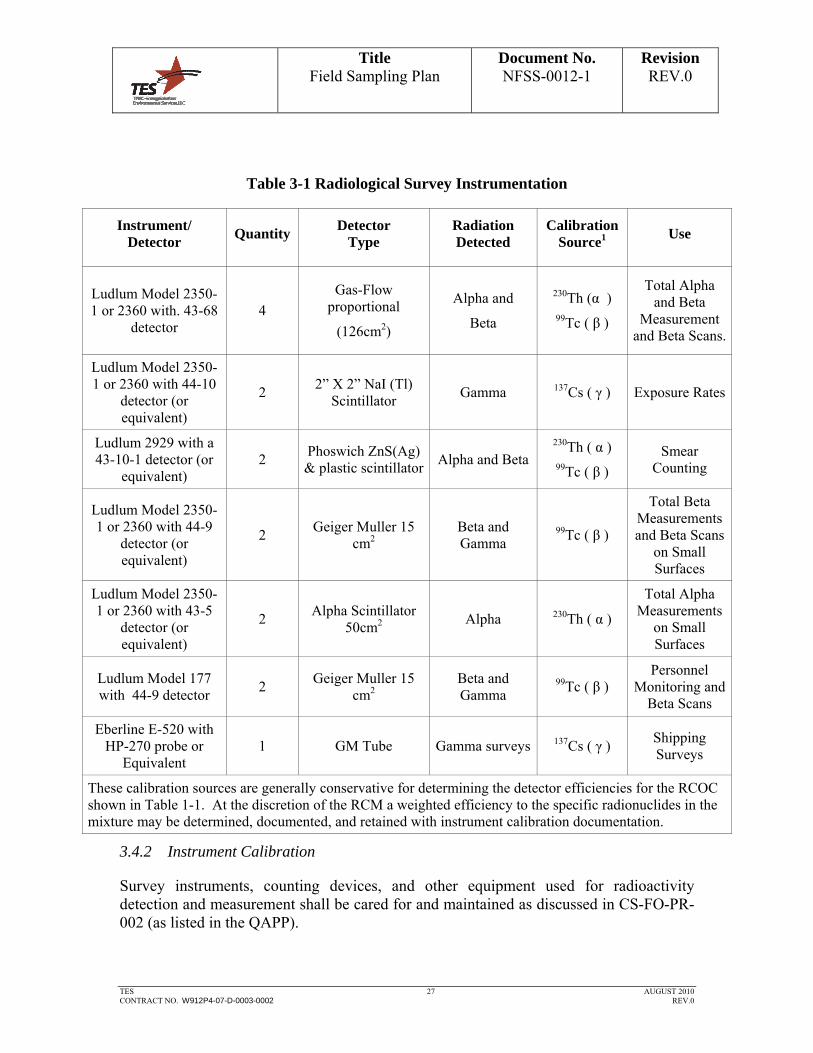
Radiation detection and measurement instrumentation will be selected based on the type and quantity of radiation to be measured. The instruments used for direct measurements will be capable of detecting the radiation of concern to minimum detectable concentrations (MDCs) outlined in Section 3.4.4. The instrumentation to be used by the TES project team is provided in Table 3-1.
The TES project team plans to use the Ludlum Model 2350-1 Data Logger or equivalent with gas flow proportional detectors for building surface scans and direct measurements
of total alpha+beta5 surface activity. Sodium Iodide (NaI(Tl)) scintillation detectors will
be used for gamma radiation scans. The Data Logger is a portable microprocessor computer based counting instrument capable of operation with NaI(Tl) gamma scintillation, gas-flow proportional, GM, and zinc sulfide (ZnS) scintillation detectors. The Data Logger is capable of retaining in memory the survey results and instrument/detector parameters for up to 1,000 measurements. This data is then downloaded to a computer for subsequent reporting and analysis.
The Ludlum Model 43-68 (126 cm2), gas-flow proportional detector with 0.8 mg/cm2 Mylar windows will be used for surface scans and direct alpha+beta measurements and a Ludlum Model 44-10, a 2"×2" NaI(Tl) gamma scintillation detector for gamma radiation scans and field screening of soil cores. Other instruments and detectors may be used based on the progress of survey activities. Smears for removable surface activity measurements and airborne particulate samples will be analyzed using a Ludlum Model 2929 or equivalent. Instruments will be operated in accordance with CS-FO-PR-005, General Operations of Radiological Survey Instruments. Additional operational information on use of the Ludlum Model 2350-1 data loggers will be in accordance with Procedures CP-INST-201, Operation of the Ludlum Model 2350-1 Series Data Loggers, and CP-CSA-203, Ludlum Model 2350-1 Series Data Logger Download Operation.
5 Alpha+beta measurements are performed using either a Geiger-Mueller counter or a gas
proportional detector operated at an alpha+beta voltage.
Title Field Sampling Plan
Document No. NFSS-0012-1
Revision REV.0
TES 27 AUGUST 2010 CONTRACT NO. W912P4-07-D-0003-0002 REV.0
Table 3-1 Radiological Survey Instrumentation
Instrument/ Detector
Quantity Detector
Type Radiation Detected
Calibration Source1
Use
Ludlum Model 2350-1 or 2360 with. 43-68
detector 4
Gas-Flow proportional
(126cm2)
Alpha and
Beta
230Th (α ) 99Tc ( β )
Total Alpha and Beta
Measurement and Beta Scans.
Ludlum Model 2350-1 or 2360 with 44-10
detector (or equivalent)
2 2” X 2” NaI (Tl)
Scintillator Gamma 137Cs ( γ ) Exposure Rates
Ludlum 2929 with a 43-10-1 detector (or
equivalent) 2
Phoswich ZnS(Ag) & plastic scintillator
Alpha and Beta 230Th ( α ) 99Tc ( β )
Smear Counting
Ludlum Model 2350-1 or 2360 with 44-9
detector (or equivalent)
2 Geiger Muller 15
cm2 Beta and Gamma
99Tc ( β )
Total Beta Measurements and Beta Scans
on Small Surfaces
Ludlum Model 2350-1 or 2360 with 43-5
detector (or equivalent)
2 Alpha Scintillator
50cm2 Alpha 230Th ( α )
Total Alpha Measurements
on Small Surfaces
Ludlum Model 177 with 44-9 detector
2 Geiger Muller 15
cm2 Beta and Gamma
99Tc ( β ) Personnel
Monitoring and Beta Scans
Eberline E-520 with HP-270 probe or
Equivalent 1 GM Tube Gamma surveys 137Cs ( γ ) Shipping
Surveys
These calibration sources are generally conservative for determining the detector efficiencies for the RCOC shown in Table 1-1. At the discretion of the RCM a weighted efficiency to the specific radionuclides in the mixture may be determined, documented, and retained with instrument calibration documentation.
3.4.2 Instrument Calibration
Survey instruments, counting devices, and other equipment used for radioactivity detection and measurement shall be cared for and maintained as discussed in CS-FO-PR-002 (as listed in the QAPP).

Title Field Sampling Plan
Document No. NFSS-0012-1
Revision REV.0
TES 28 AUGUST 2010 CONTRACT NO. W912P4-07-D-0003-0002 REV.0
All radiological survey instruments will be calibrated at least annually using approved procedures, using sources traceable to the National Institute of Standards and Technology (NIST), and using industry standard calibration equipment.
The instrument calibration includes:
high voltage calibration,
discriminator/threshold calibration,
window calibration,
alarm operation verification, and
scaler calibration verification.
The detector calibration includes:
operating voltage determination,
calibration constant determination, and
dead time correction determination.
Calibration labels showing the instrument identification number, calibration date, and calibration due date are attached to all portable field instruments. The Radiological Control Technicians (RCT) are trained to check the instrument calibration label before each use to ensure they are using a properly calibrated instrument.
3.4.3 Response Checks and Radioactive Sources
Prior to use on-site by the TES project team, all instrument calibrations will be verified and initial response data collected by the Radiological Control Technicians (RCT). These initial measurements may be used to establish instrument control charts and performance standards (response ranges) in which the instruments can be tested against on a daily basis when in use. An acceptable response for field instrumentation is an instrument reading within ±20% of the established check source value. Control charts for the Ludlum Model 2929 with a 43-10-1 detector will be established in accordance with CS-FO-PR-004, QA/QC of Portable Radiological Survey Instruments.
The daily response tests results will be documented and compared to these operating parameters and ranges to ensure that the instrumentation was functioning properly. When an instrument fails a response check, the results will be investigated to determine

Title Field Sampling Plan
Document No. NFSS-0012-1
Revision REV.0
TES 29 AUGUST 2010 CONTRACT NO. W912P4-07-D-0003-0002 REV.0
the cause of failure. In the event that the instrument is not functioning properly, the instrument will be removed from service for repair and re-calibration.
All radioactive sources used for calibration or efficiency determinations for this project will be representative or conservative to the instrument's response of the identified nuclides that are present at the site and are traceable to NIST.
3.4.4 MDC Calculations
Count times for field measurements will be set to see less than 50% of the limits specified in Section 1.3 of this plan. Specifically the MDCs shown in Table 3-2 will be met. If the background study shows that lower detection limits are needed in order to determine that materials are not statistically different from background, then lower MDC limits will be used. In practice the MDCs for the static alpha, static alpha+beta, removable alpha, and removable beta will likely achieve approximately 10% of the limits shown in Section 1.3. Surface scans will be performed to 50% of the limits as shown in Table 3-2.
While the MDCs in Table 3-2 will be low enough to demonstrate what would be allowable by Regulatory Guide 1.86, to demonstrate that the materials are not distinguishable from background will require a material specific background study to be performed as described in Section 5.2 of this plan. This background study will include the building materials that are not-impacted and will include sheet metal, poured concrete, and concrete block. A one minute count time will be used for all static measurements during the background study. A shorter count time may be used during release surveys if it is sufficient to see the desired background levels determined during the background study and evaluation.
Table 3-2 MDCs for Field Instruments
Measurement MDC (dpm/100cm2)
Static Alpha 1,000
Removable Alpha 100
Static Alpha+Beta and building surface scans
2,500
Removable Beta 250
MDCs based on 50% of the Regulatory Guide 1.86 criteria shown in Section 1.3. The background study will determine the required MDCs for the survey. Static count times during building surveys will be less than or equal to 1 minute.
Title Field Sampling Plan
Document No. NFSS-0012-1
Revision REV.0
TES 30 AUGUST 2010 CONTRACT NO. W912P4-07-D-0003-0002 REV.0
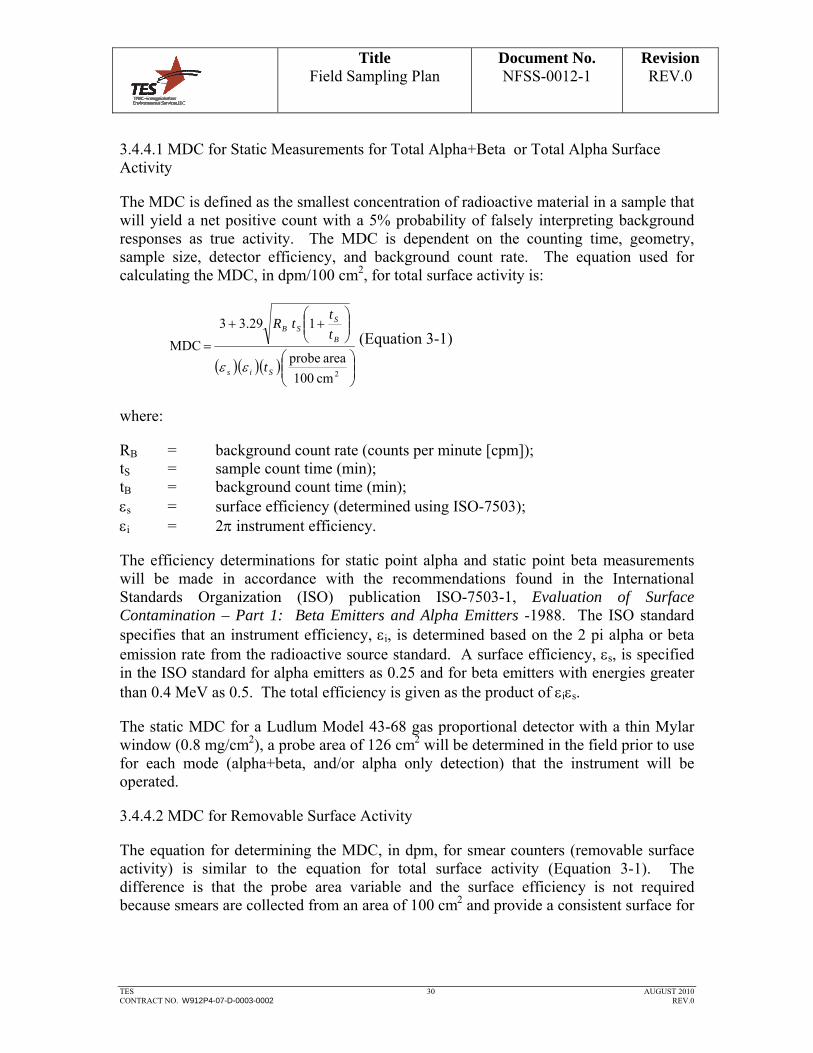
3.4.4.1 MDC for Static Measurements for Total Alpha+Beta or Total Alpha Surface Activity
The MDC is defined as the smallest concentration of radioactive material in a sample that will yield a net positive count with a 5% probability of falsely interpreting background responses as true activity. The MDC is dependent on the counting time, geometry, sample size, detector efficiency, and background count rate. The equation used for calculating the MDC, in dpm/100 cm2, for total surface activity is:
2cm100
areaprobe
129.33
MDC
Sis
B
SSB
t
t
ttR
(Equation 3-1)
where:
RB = background count rate (counts per minute [cpm]); tS = sample count time (min); tB = background count time (min); s = surface efficiency (determined using ISO-7503); i = 2 instrument efficiency.
The efficiency determinations for static point alpha and static point beta measurements will be made in accordance with the recommendations found in the International Standards Organization (ISO) publication ISO-7503-1, Evaluation of Surface Contamination – Part 1: Beta Emitters and Alpha Emitters -1988. The ISO standard specifies that an instrument efficiency, i, is determined based on the 2 pi alpha or beta emission rate from the radioactive source standard. A surface efficiency, s, is specified in the ISO standard for alpha emitters as 0.25 and for beta emitters with energies greater than 0.4 MeV as 0.5. The total efficiency is given as the product of is.
The static MDC for a Ludlum Model 43-68 gas proportional detector with a thin Mylar window (0.8 mg/cm2), a probe area of 126 cm2 will be determined in the field prior to use for each mode (alpha+beta, and/or alpha only detection) that the instrument will be operated.
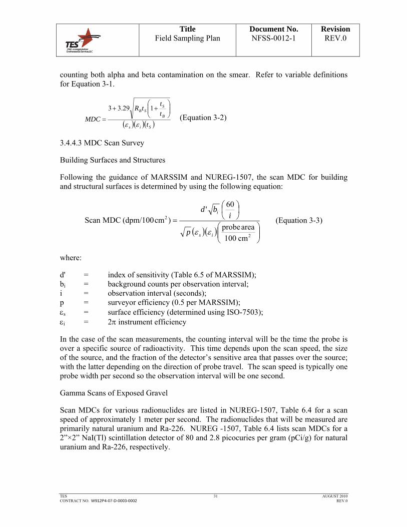
3.4.4.2 MDC for Removable Surface Activity
The equation for determining the MDC, in dpm, for smear counters (removable surface activity) is similar to the equation for total surface activity (Equation 3-1). The difference is that the probe area variable and the surface efficiency is not required because smears are collected from an area of 100 cm2 and provide a consistent surface for
Title Field Sampling Plan
Document No. NFSS-0012-1
Revision REV.0
TES 31 AUGUST 2010 CONTRACT NO. W912P4-07-D-0003-0002 REV.0
counting both alpha and beta contamination on the smear. Refer to variable definitions for Equation 3-1.
Sis
B
SSB
t
t
ttR
MDC
129.33
(Equation 3-2)
3.4.4.3 MDC Scan Survey
Building Surfaces and Structures
Following the guidance of MARSSIM and NUREG-1507, the scan MDC for building and structural surfaces is determined by using the following equation:
2
2
cm100
areaprobe
60'
)cm(dpm/100MDCScan
is
i
p
ibd
(Equation 3-3)
where:
d' = index of sensitivity (Table 6.5 of MARSSIM); bi = background counts per observation interval; i = observation interval (seconds); p = surveyor efficiency (0.5 per MARSSIM); s = surface efficiency (determined using ISO-7503); i = 2 instrument efficiency
In the case of the scan measurements, the counting interval will be the time the probe is over a specific source of radioactivity. This time depends upon the scan speed, the size of the source, and the fraction of the detector’s sensitive area that passes over the source; with the latter depending on the direction of probe travel. The scan speed is typically one probe width per second so the observation interval will be one second.
Gamma Scans of Exposed Gravel
Scan MDCs for various radionuclides are listed in NUREG-1507, Table 6.4 for a scan speed of approximately 1 meter per second. The radionuclides that will be measured are primarily natural uranium and Ra-226. NUREG -1507, Table 6.4 lists scan MDCs for a 2”×2” NaI(Tl) scintillation detector of 80 and 2.8 picocuries per gram (pCi/g) for natural uranium and Ra-226, respectively.
Title Field Sampling Plan
Document No. NFSS-0012-1
Revision REV.0
TES 32 AUGUST 2010 CONTRACT NO. W912P4-07-D-0003-0002 REV.0
3.4.5 Instrument Quality Control
Daily instrument quality control (QC) checks will be documented and performed before and after each day's work and as outlined in this FSP.
3.5 OFF-SITE LABORATORY ANALYSIS
Off-site laboratory analyses of samples may include the following:
Samples of waste to be removed from Building 401, to include volumetric solids, liquids, and debris, (or other samples) obtained to properly classify and profile wastes for disposal or acceptance at recycling facilities. These samples are needed: to verify that conditions of the WAC are satisfied, to complete required waste profile records and declarations (e.g., Hazardous Waste Analysis, and PCB Certifications) and to complete U.S. Department of Transportation (DOT), U.S. NRC, and disposal/recycling facility required manifests and shipping papers.
Liquid waste (wastewater), including water from sedimentation and erosion control areas, water drained and collected from debris following building demolition, decontamination liquids, and surface water runoff from established project work zones.
Samples of off-site gravel borrow material proposed for use as pre or post-demolition backfill.
Off-site laboratory analyses of gravel, building debris, waste and wastewater samples will address the parameters and analysis methods identified in the Quality Assurance Project Plan (QAPP).
4.0 NON MEASUREMENT DATA ACQUISITION
This plan has used the information contained in previous studies to define the radionuclides of concern and the number and types of surveys that will be described in Section 5.0 of this plan.
5.0 SURVEY/SAMPLING DESIGN
5.1 INTRODUCTION
The TES project team will perform surveys according to standard operations procedures as identified in the QAPP, this plan, and applicable requirements of the Accident Prevention Plan / Site Safety and Health Plan. The types of surveys supporting the project are detailed below in the chronological order that they are likely to occur.
Title Field Sampling Plan
Document No. NFSS-0012-1
Revision REV.0
TES 33 AUGUST 2010 CONTRACT NO. W912P4-07-D-0003-0002 REV.0
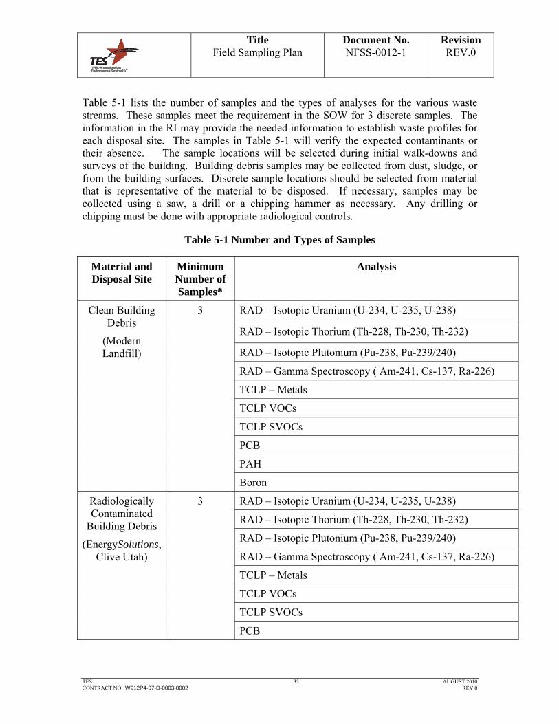
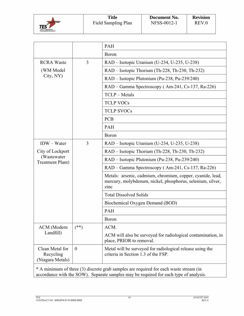
Table 5-1 lists the number of samples and the types of analyses for the various waste streams. These samples meet the requirement in the SOW for 3 discrete samples. The information in the RI may provide the needed information to establish waste profiles for each disposal site. The samples in Table 5-1 will verify the expected contaminants or their absence. The sample locations will be selected during initial walk-downs and surveys of the building. Building debris samples may be collected from dust, sludge, or from the building surfaces. Discrete sample locations should be selected from material that is representative of the material to be disposed. If necessary, samples may be collected using a saw, a drill or a chipping hammer as necessary. Any drilling or chipping must be done with appropriate radiological controls.
Table 5-1 Number and Types of Samples
Material and Disposal Site
Minimum Number of Samples*
Analysis
RAD – Isotopic Uranium (U-234, U-235, U-238)
RAD – Isotopic Thorium (Th-228, Th-230, Th-232)
RAD – Isotopic Plutonium (Pu-238, Pu-239/240)
RAD – Gamma Spectroscopy ( Am-241, Cs-137, Ra-226)
TCLP – Metals
TCLP VOCs
TCLP SVOCs
PCB
PAH
Clean Building Debris
(Modern Landfill)
3
Boron
RAD – Isotopic Uranium (U-234, U-235, U-238)
RAD – Isotopic Thorium (Th-228, Th-230, Th-232)
RAD – Isotopic Plutonium (Pu-238, Pu-239/240)
RAD – Gamma Spectroscopy ( Am-241, Cs-137, Ra-226)
TCLP – Metals
TCLP VOCs
TCLP SVOCs
Radiologically Contaminated
Building Debris
(EnergySolutions, Clive Utah)
3
PCB
Title Field Sampling Plan
Document No. NFSS-0012-1
Revision REV.0
TES 34 AUGUST 2010 CONTRACT NO. W912P4-07-D-0003-0002 REV.0
PAH
Boron
RAD – Isotopic Uranium (U-234, U-235, U-238)
RAD – Isotopic Thorium (Th-228, Th-230, Th-232)
RAD – Isotopic Plutonium (Pu-238, Pu-239/240)
RAD – Gamma Spectroscopy ( Am-241, Cs-137, Ra-226)
TCLP – Metals
TCLP VOCs
TCLP SVOCs
PCB
PAH
RCRA Waste
(WM Model City, NY)
3
Boron
RAD – Isotopic Uranium (U-234, U-235, U-238)
RAD – Isotopic Thorium (Th-228, Th-230, Th-232)
RAD – Isotopic Plutonium (Pu-238, Pu-239/240)
RAD – Gamma Spectroscopy ( Am-241, Cs-137, Ra-226)
Metals: arsenic, cadmium, chromium, copper, cyanide, lead, mercury, molybdenum, nickel, phosphorus, selenium, silver, zinc
Total Dissolved Solids
Biochemical Oxygen Demand (BOD)
PAH
IDW – Water
City of Lockport (Wastewater
Treatment Plant)
3
Boron
ACM (Modern Landfill)
(**) ACM.
ACM will also be surveyed for radiological contamination, in place, PRIOR to removal.
Clean Metal for Recycling
(Niagara Metals)
0 Metal will be surveyed for radiological release using the criteria in Section 1.3 of the FSP.
* A minimum of three (3) discrete grab samples are required for each waste stream (in accordance with the SOW). Separate samples may be required for each type of analysis.

Title Field Sampling Plan
Document No. NFSS-0012-1
Revision REV.0
TES 35 AUGUST 2010 CONTRACT NO. W912P4-07-D-0003-0002 REV.0
** The number of samples will be determined by the licensed Asbestos inspector. Analysis and Disposal will be in accordance with applicable State and Federal Regulations.
5.2 MATERIAL SPECIFIC BACKGROUND STUDY
5.2.1 Rationale
A background study to establish the material specific background of each type of building material will be performed using non-impacted surfaces within Building 401. The areas will be selected using the ORISE surveys as guidance for locations where no activity was detected. Suitable background locations will be located such that the material is representative but unaffected by FUSRAP contamination.
5.2.2 Survey Method
Static alpha, static alpha+beta, removable alpha, removable beta, and direct gamma exposure rate measurements will be obtained for the background study. Instrumentation will be the same instrument types that will be used during the project surveys. More than one survey instrument will be used for static alpha, and static alpha+beta measurements.
A study will be performed for: metal, poured concrete (including the silos), and block concrete. If other material types are encountered that cannot be represented by the material backgrounds, then additional materials will be evaluated on a case by case basis to establish additional data sets as necessary.
For each material approximately 4 separate areas will be selected and within each area 10 measurements of each (static alpha, static alpha+beta, removable alpha, removable beta, and gamma exposure) will be obtained at unique locations within the area. This will establish a data set of 40 independent measurements for each material and each type of measurement.
It is expected that static measurement count times will be 1 minute each unless otherwise directed by the RCM to achieve lower detection limits.
The following measurements will be taken using the 43-68 gas proportional detectors at each location:
● A shielded (with a plexiglass shield over the detector window) field background.
● A measurement of the material surface.
Concrete samples should be collected at three locations and analyzed to determine the concentrations of naturally occurring radionuclides (U-234, U-235, U-238, Ra-226, Th-230, Th-232, and Th-228).

Title Field Sampling Plan
Document No. NFSS-0012-1
Revision REV.0
TES 36 AUGUST 2010 CONTRACT NO. W912P4-07-D-0003-0002 REV.0
5.2.3 Documentation
Each background measurement will be evaluated to determine the “material specific” background. The material-specific background will be determined by subtracting the plexiglass shielded field background measurement from the measurement of the material surface. The background data sets will be tabulated, summarized and basic statistics performed to determine the mean, standard deviation, minimum and maximum.
It is anticipated that the mean + 3 sigma will be used to establish a point above which any measurement will be assumed to be statistically above background. However, until the evaluation of the data is completed other methods may be utilized to establish the background measurement criteria.
The background study will be documented, reviewed and submitted to the USACE for approval prior to use for surveying materials for free release or for recycle use.
5.3 (PRE-DEMOLITION) INITIAL RADIOLOGICAL SURVEYS OF OUTSIDE AREAS
5.3.1 Rationale
Gamma scans will be performed of outside areas out to 15 meters beyond the work area to establish the existing radiological conditions. This data will establish the comparison for post-surveys to insure demolition activities do not radiologically contaminate other areas and to prevent contamination from outside areas from contaminating the demolition debris.
5.3.2 Survey Method
Gamma scans of the areas will be performed using a 2”X 2” NaI(Tl) detector (Ludlum Model 44-10 detector or equivalent) with a 2350-1 data logger or equivalent. Surveys will be performed moving the detector in a serpentine pattern at a speed of no greater than 1 meter per second, covering at least 50% of the area. The surveys will identify posted areas and areas of elevated radioactivity in the soils. Elevated areas may be covered with a geotextile fabric and 4 inch layer of 2 inch crusher stone, as described in the Demolition Plan.
5.3.3 Documentation
The survey will be documented on a survey map with areas of elevated (greater than 2 times the area background) exposure rates (or count rates) clearly marked. Areas of elevated activity will be reviewed by the RCM and PM.

Title Field Sampling Plan
Document No. NFSS-0012-1
Revision REV.0
TES 37 AUGUST 2010 CONTRACT NO. W912P4-07-D-0003-0002 REV.0
5.4 (PRE-DEMOLITION) INITIAL RADIOLOGICAL SURVEYS OF BUILDING 401 AND THE
SILOS
5.4.1 Rationale
These surveys will identify materials and surfaces that will need to be disposed of as LLW. Building scans and removable contamination levels will be used to identify areas previously identified and shown as UINs on the Attachment 1 drawings. These areas will be surveyed and areas exceeding the limits in Section 1.3 will be marked for remediation and segregation as radiologically contaminated waste. Other suspect areas will be investigated including
Horizontal surfaces of accessible I beams within rooms 117, 121, and 122 will be surveyed with a 50% scan frequency due to the previous identification of elevated surfaces
Drains on the second floor, ventilation equipment, fans, and penetrations will be surveyed at the discretion of the RCM to identify materials that need to be segregated as radioactive waste.
5.4.2 Survey Method
A gamma scan of the building will be performed using a 2”X2” NaI(Tl) detector with a Ludlum model 2350-1 data logger. The detector will be held approximately 10 cm from the floor and scans performed at a rate of approximately 1 meter per second. Approximately 25% of the floor areas will be scanned and biased surveys will also be performed of suspect areas (drains, crevices, penetrations, etc.). Areas exceeding 2 times background will be investigated.
Surface alpha+beta scanning and smears for removable contamination will be performed on the first floor at a scan frequency of approximately 25% of the area to document the initial condition for comparison with final condition of the as slab after demolition. Walls (below 2 meters) and floors on the second level will also be scanned at approximately 25% frequency or at the discretion of the RCM. Work and surveys will begin with the areas previously identified to be contaminated and recommended for follow-up scanning (guidance obtained from Attachment 1 drawings in this plan and the Bechtel National Report). A building wide confirmatory scanning will follow beginning on the roof and work will continue down through the structure with particular attention to suspect areas and areas not previously surveyed. The silos should be surveyed more thoroughly during this survey since there does not appear to be characterization data on the silos.
Survey personnel will mark using bright orange paint and/or detail on a survey map the sample and measurement locations exceeding the limits from the background study of

Title Field Sampling Plan
Document No. NFSS-0012-1
Revision REV.0
TES 38 AUGUST 2010 CONTRACT NO. W912P4-07-D-0003-0002 REV.0
this plan to ensure that the sample and/or measurement can be referenced to a physical site location.
5.4.3 Documentation
The survey will be documented on a survey map with areas exceeding the surface criteria in Section 1.3 clearly marked. Gamma scan measurements exceeding the scan MDC will also be marked on the survey map. Areas of elevated activity will be reviewed by the RCM and PM.
If the first floor (floor) areas are noted to contain removable contaminated above the criteria in Section 1.3 (Regulatory Guide 1.86 removable contamination criteria), consideration will be given to covering the areas prior to demolition, as described in the Demolition Plan. This will be done to prevent the building demolition materials from becoming contaminated when the building is razed.
5.5 (PRE-DEMOLITION) SURVEYS FOR NON-RADIOLOGICAL CONTAMINANTS
5.5.1 Rationale
These surveys provide the basis for the identification of ACM, hazardous materials and chemical contaminants.
5.5.2 Metals, SVOC, VOC, and PCB Sampling and Analyses of Waste Samples
TCLP analysis is an Environmental Protection Agency (EPA) SW-846 analytical method (Method 1311) that simulates sanitary landfill contaminant leaching in waste samples. Based upon concentrations of the TCLP constituents and guidelines set forth in 40CFR261.4, where the solid waste samples can be deemed hazardous or non-hazardous. The number of TCLP samples will be determined based on the hazard assessment. Each waste stream will have 3 representative samples analyzed for TCLP.
5.5.3 Asbestos Sampling and Analyses
5.5.3.1 Asbestos Sampling
A properly trained Asbestos Hazard Emergency Response Act (AHERA)-accredited Asbestos Building Inspector whose licensure is current in the State of New York will perform asbestos sampling for asbestos containing materials (ACM). The number of samples will be determined based on the asbestos hazard assessment.
ACM sampling and the building inspection shall comply with the procedures specified in the EPA’s AHERA regulation (40CFR763.86).

Title Field Sampling Plan
Document No. NFSS-0012-1
Revision REV.0
TES 39 AUGUST 2010 CONTRACT NO. W912P4-07-D-0003-0002 REV.0
5.5.3.2 Asbestos Analyses
ACM is defined in the EPA’s National Emission Standards for Hazardous Air Pollutants (NESHAPs) as materials containing more than 1 percent asbestos as determined by polarized light microscopy (PLM) utilizing the method specified in the EPA’s AHERA regulation (40CFR763).
5.5.3.3 Radiological Survey of ACM
Prior to removal of the ACM, the materials will be surveyed in place using alpha+beta scanning. Any material above background will be marked for removal as radioactively contaminated ACM. The surveys shall be documented.
5.5.4 Lead Sampling and Analyses
Lead Paint adhering to the surfaces meets the WAC for both recycling and disposal. No plans for Lead Sampling and Analysis are scheduled for the Site.
5.5.5 PCB Sampling and Analyses
5.5.5.1 PCB Sampling
PCB levels reported in the previously collected samples of the floor drains and sumps in the RI will be used for disposal. Confirmatory sampling of collected liquids and sludges and building debris will be performed.
5.5.6 Chemical Sample Protocol
Samples for chemical analyses will be collected in appropriate containers, evaluated to the appropriate holding times, and analyzed by the laboratory specified in Section 2.1.
5.6 IN PROCESS RADIOLOGICAL SURVEYS OF BUILDING 401 AND THE SILOS
In process surveys will be performed as directed by the RCM during removal of contaminated items to verify the conditions. These surveys will be performed as part of the operational program described in the RSP.
5.7 (PRE-DEMOLITION) MARSSIM- BASED FINAL RADIOLOGICAL SURVEYS OF
BUILDING 401 AND THE SILOS
5.7.1 Rationale
After radiologically contaminated materials have been removed and or wrapped and marked (for structural materials that cannot be removed prior to building demolition) a MARSSIM-based final status survey will be performed of Building 401 and the silos.

Title Field Sampling Plan
Document No. NFSS-0012-1
Revision REV.0
TES 40 AUGUST 2010 CONTRACT NO. W912P4-07-D-0003-0002 REV.0
This survey is the final confirmation that the building surfaces are not radiologically contaminated, and can be demolished and prepared for shipment for disposal as non-radioactive.
5.7.2 MARSSIM Final Radiological Survey Methods
5.7.2.1 Survey Overview
Building 401 and the silos will be surveyed using MARSSIM Class 3 radiological survey protocols, except for areas where previous remediation was conducted. Areas where there was remediation will be surveyed as MARSSIM Class 1 but the areas will be limited to the area covering and surrounding the remediation (out to a buffer of 5 feet surrounding the remediated area). A class 3 survey can be any size but the sizes for this survey will be based on the historical information with a greater survey frequency of scans and measurements in areas that are known to have elevated radioactivity. If the MARSSIM Class 3 survey results indicate the presence of contamination at 75% of the limits in Section 1.3, then: the number of measurements per unit area, and the scanning frequency should be increased to correspond to a Class 2 or Class 1 survey unit (at the discretion of the RCM). Class 1 and Class 2 areas will not be gridded as described in MARSSIM. Where available the grid markings that were developed during the ORISE survey will be used as reference for the survey documentation.
Survey units will be established to complete the Final Status Survey and will be based on historical information and potential for residual contamination. Survey packages will be developed for each survey unit that describe the survey unit, survey instructions, the number and types of measurements and/or samples required, codes for tracking the data, and identify any abnormal conditions or safety concerns that may be encountered during the survey.
The RCM or designee shall perform a walk-down of each survey unit during the development of the survey package.
Expected survey units are described in Table 5-1. These surveys may change at the discretion of the RCM based on information obtained during the remediation or area walk-downs. Note: since the first floor floors will not be free released a final survey of the first-floor floors will not be performed.
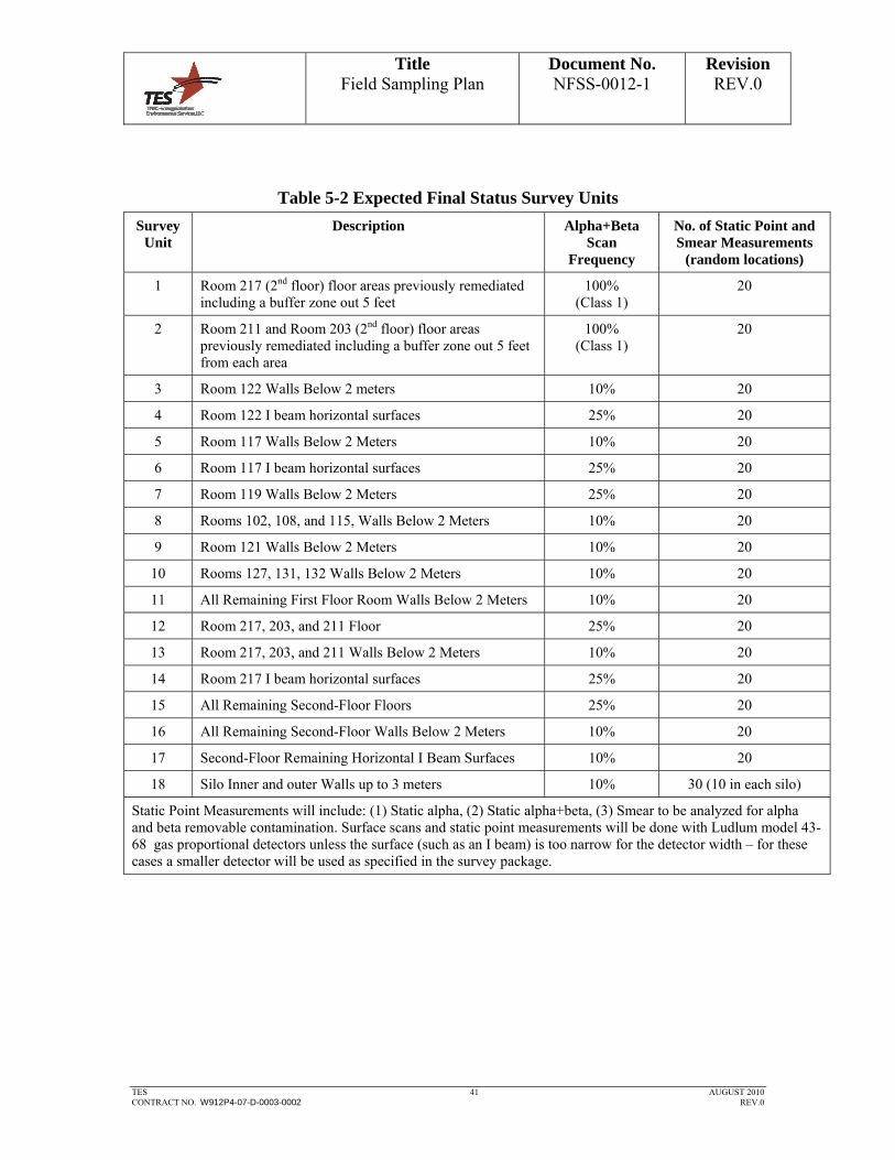
Title Field Sampling Plan
Document No. NFSS-0012-1
Revision REV.0
TES 41 AUGUST 2010 CONTRACT NO. W912P4-07-D-0003-0002 REV.0
Table 5-2 Expected Final Status Survey Units
Survey Unit
Description Alpha+Beta Scan
Frequency
No. of Static Point and Smear Measurements
(random locations)
1 Room 217 (2nd floor) floor areas previously remediated including a buffer zone out 5 feet
100% (Class 1)
20
2 Room 211 and Room 203 (2nd floor) floor areas previously remediated including a buffer zone out 5 feet from each area
100% (Class 1)
20
3 Room 122 Walls Below 2 meters 10% 20
4 Room 122 I beam horizontal surfaces 25% 20
5 Room 117 Walls Below 2 Meters 10% 20
6 Room 117 I beam horizontal surfaces 25% 20
7 Room 119 Walls Below 2 Meters 25% 20
8 Rooms 102, 108, and 115, Walls Below 2 Meters 10% 20
9 Room 121 Walls Below 2 Meters 10% 20
10 Rooms 127, 131, 132 Walls Below 2 Meters 10% 20
11 All Remaining First Floor Room Walls Below 2 Meters 10% 20
12 Room 217, 203, and 211 Floor 25% 20
13 Room 217, 203, and 211 Walls Below 2 Meters 10% 20
14 Room 217 I beam horizontal surfaces 25% 20
15 All Remaining Second-Floor Floors 25% 20
16 All Remaining Second-Floor Walls Below 2 Meters 10% 20
17 Second-Floor Remaining Horizontal I Beam Surfaces 10% 20
18 Silo Inner and outer Walls up to 3 meters 10% 30 (10 in each silo)
Static Point Measurements will include: (1) Static alpha, (2) Static alpha+beta, (3) Smear to be analyzed for alpha and beta removable contamination. Surface scans and static point measurements will be done with Ludlum model 43-68 gas proportional detectors unless the surface (such as an I beam) is too narrow for the detector width – for these cases a smaller detector will be used as specified in the survey package.

Title Field Sampling Plan
Document No. NFSS-0012-1
Revision REV.0
TES 42 AUGUST 2010 CONTRACT NO. W912P4-07-D-0003-0002 REV.0
5.7.2.2 Survey Methodology
Alpha+Beta Scans
Surface activity scans will be performed with the frequency shown in Table 5-1 and as specified in the survey package. The scans will be performed by moving the detector over the surface being scanned at a height of approximately 0.5 inches and at a rate of approximately 1 detector’s width per second. While scanning, the technician will monitor the audible output of the survey meter. Areas of elevated activity will be investigated by collecting biased static point alpha and static point alpha+beta measurements. Areas of activity exceeding 5,000 dpm/100cm2 alpha+beta, or as otherwise determined by the background study and specified by the RCM, will be marked and the corresponding static point measurements recorded.
Static Point Alpha and Static Point Alpha+Beta Measurements
Static point alpha and alpha+beta measurements will be taken at each static point measurement location. Measurements will be at predefined random locations (established using a pair of random numbers and then establishing the measurement location on the survey map).
Direct measurements will be taken using large area gas flow proportional detectors, (126 cm2) in direct contact with the surface being measured.
For each survey unit a minimum of 4 shielded field background measurements will be required for each type of measurement (i.e., 4 shielded background measurements in the alpha+ beta mode, and 4 shielded background measurements in the alpha mode). The detector shield is simply a plexiglass or cardboard shield sufficient to shield out the surface activity while still allowing the detector to respond to ambient gamma radiation, effectively establishing the instrument background. The average of the 4 field background measurements will be used to convert gross count rate to net count rate.
The location of each measurement will be marked in the field and its location recorded on a drawing.
Smears for Removable Alpha and Removable Beta Contamination
At each static point measurement location, except on those surfaces subjected to environmental weathering, a smear will be collected to assess removable contamination. Smears will be analyzed on a Ludlum Model 2929 for simultaneous alpha and beta determinations.
Miscellaneous Samples

Title Field Sampling Plan
Document No. NFSS-0012-1
Revision REV.0
TES 43 AUGUST 2010 CONTRACT NO. W912P4-07-D-0003-0002 REV.0
Miscellaneous samples will be collected as specified in the associated survey package. Sample media may include, sludge, concrete debris, etc. Minimum sample volumes are specified in the QAPP.
5.7.2.3 Sample Handling and Analysis
Samples will be sent to the off-site laboratory and analyzed for isotopic uranium, isotopic thorium, Ra-226, Cs-137 and Am-241.
5.7.2.4 Instrumentation
Instrumentation is as specified in Section 3.4 of this plan. Instrument logged data will be downloaded from the survey instrument into a database for storage, analysis, and reporting on a daily basis.
Results will be printed out, reviewed for completeness with the survey package requirements, and reviewed for analysis results that exceed the criteria in Section1.3.
5.7.2.5 Survey Package Documentation Review
The project team will maintain records of surveys for each area according to project procedures (as listed in the QAPP). The survey records may include the following information depending upon the survey design and protocols:
Worksheet providing identification, survey location information, general survey instructions, and any specific survey instructions.
Comments from the survey technician regarding any unusual situation encountered while surveying.
Diagram/map of the area surveyed as available.
Photographs of the survey area, as necessary, to show special or unique conditions.
Printout of laboratory analysis results (if performed).
Ludlum Model 2350-1 data files and values for all radiation survey measurements.
Gamma radiation scan results.

Title Field Sampling Plan
Document No. NFSS-0012-1
Revision REV.0
TES 44 AUGUST 2010 CONTRACT NO. W912P4-07-D-0003-0002 REV.0
Data and document control will include the maintenance of the raw data files, translated data files, and documentation of corrections made to the data. The data files will be backed up on a daily basis.
The RCM or designee will review the completed survey packages to ensure that all required surveys have been performed in compliance with this plan and the QAPP. In addition, the review will ensure that the completed survey packages contain all the necessary information to evaluate the data to the DQO decision rules listed the QAPP.
The survey package data will be compared to the material specific backgrounds that were established.
5.7.2.6 Reporting
Once all Final Status Survey Packages are completed and areas found to be less than the criteria of no activity statistically different from background, a report will be prepared summarizing the results. The report shall be reviewed by the RCM, a Certified Health Physicist, CQC, and the PM and transmitted to the USACE.
Building Demolition will then proceed.
5.8 IN-PROCESS DEMOLITION SURVEYS
5.8.1 Rationale
Verification surveys will be performed during demolition and as wastes are being staged for waste disposition. These surveys are simply a final check to verify the absence of radioactive material in the material segregated for disposal as non-radiologically contaminated and the material that will be sent for recycling.
5.8.2 Survey Method
Surveys will be performed using gamma scanning for waste piles, and surface contamination scans for metal to be recycled. The measurements will be such that approximately 5% of the material receives a verification check.
Notify the USACE within one (1) day of any material found identifying radioactive material.
5.8.3 Documentation
In-Process demolition surveys will be performed as a job coverage type of survey. The verification surveys of the waste piles will be recorded in a survey log book or on a survey form – the results will clearly note that the measurements and material is

Title Field Sampling Plan
Document No. NFSS-0012-1
Revision REV.0
TES 45 AUGUST 2010 CONTRACT NO. W912P4-07-D-0003-0002 REV.0
acceptable for free release. Elevated measurements will also be recorded and the material segregated for additional evaluation or disposal as LLRW.
5.9 (POST-DEMOLITION) RADIOLOGICAL SURVEYS OF OUTSIDE AREAS AND BUILDING
SLAB
5.9.1 Rationale
Gamma scans will be performed of outside areas out to 15 meters beyond the work area to determine the final radiological conditions. This data will be compared to the pre- demolition surveys to insure the demolition activities did not radiologically contaminate other areas.
The Building Slab will be surveyed to ensure that the removable contamination does not exceed the regulatory guide 1.86 derived removable contamination limits shown in Section 1.3 of this plan.
5.9.2 Survey Method
Gamma scans of the areas will be performed using a 2”X 2” NaI(Tl) detector (Ludlum Model 44-10 detector or equivalent) with a 2350-1 data logger or equivalent. Surveys will be performed moving the detector in a serpentine pattern at a speed of no greater than 1 meter per second, covering at least 50% of the area. The surveys will identify posted areas and areas of elevated radioactivity in the soils. Elevated areas may be covered with a geotextile fabric and 4 inch layer of 2 inch crusher stone, as described in the Demolition Plan.
Surface alpha+beta scanning and smears for removable contamination will be performed on the first floor at a scan frequency of approximately 25% of the area to document the final condition of the slab. Smears will be taken at a frequency of approximately 1 per square meter and the removable contamination values compared to the removable activity limits in Section 1.3 (removable alpha < 200 dpm/100cm2, and removable beta < 500 dpm/100cm2).
5.9.3 Documentation
The survey will be documented on a survey map with areas of elevated (greater than 2 times the area background) exposure rates (or count rates) clearly marked. Areas of elevated activity will be reviewed by the RCM and PM.
Title Field Sampling Plan
Document No. NFSS-0012-1
Revision REV.0
TES 46 AUGUST 2010 CONTRACT NO. W912P4-07-D-0003-0002 REV.0
5.10 EQUIPMENT RELEASE SURVEYS
All equipment and instrumentation used in potentially contaminated areas will be scanned, and cleaned if necessary, prior to leaving the area to assure that contamination is not inadvertently moved out of controlled areas and does not interfere with accuracy of subsequent measurements. The results of these scans will be documented in the site logbook and reviewed by the RCM.
When there is a potential for contamination of containers or equipment during sample transport, suspect surfaces will be surveyed as directed by the RCM. Should decontamination be necessary, a follow-up survey will be performed to assure that all surfaces are as low as reasonably achievable (ALARA). Surveys of equipment or other items will be documented in the site logbook and reviewed by the RCM.
6.0 SAMPLE IDENTIFICATION, STORAGE, PACKAGING AND SHIPMENT
6.1 SAMPLE IDENTIFICATION
All samples will be identified using an alphanumeric code for the purpose of identification and traceability as indicated in procedure CS-FO-PR-003, Soil Surveys; Collection of Water, Sediment, Vegetation, and Soil Samples; and Chain of Custody Procedure (as listed in the QAPP), using the following sample identification system. All samples collected for analysis will be identified using an alphanumeric code.
(1) The first four characters represent the acronym for the facility (NFSS)
(2) The fifth character designates the general category describing the sampling approach.
a. B – Biased: Samples collected to provide further information about specific areas such as “hot spots” or locations suspected of having high potential for contamination.
b. R – Random: Samples collected at either a random location on a predetermined point on a random-start grid.
c. A – Background: Samples collected on-site in areas not impacted by radioactive material or collected from remote areas.
d. O – Other: Note the category on the identification label.
(3) The sixth and seventh characters are abbreviations of the medium or the type of sample collected. Also note on the sample identification label wheather the
Title Field Sampling Plan
Document No. NFSS-0012-1
Revision REV.0
TES 47 AUGUST 2010 CONTRACT NO. W912P4-07-D-0003-0002 REV.0
sample is a discrete grab sample, a composite sample, depth, elapsed time of samples, etc. as needed.
SL – Soil
SD – Sediment
TC – Transferable Contamination (smear)
MB – Base Metal
MP – Metal Plateout
DS – Drain Sediment
CN – Concrete
GW – Groundwater
SW – Surface Water
CW – Containerized Water
O - Other
(4) The eight through the eleventh characters are the unique sample number. This is the sample number contained in the sample log. These numbers should be sequential unless otherwise specified by the project management.
(5) Example of a sample code
NFSSBMB0001 – Niagara Falls Storage Site, biased, base metal, number 1
6.2 SAMPLE STORAGE
All samples will be stored in a controlled area established by the TES project team in consultation with USACE. Samples will be inspected prior to being placed in the storage area for legible identification, potential damage, adequate packaging, and traceability to sample records. Packaging and identification shall be consistent with the duration and conditions of storage. An inventory and sample retention time shall be maintained throughout the storage period. All chemical samples will be stored in appropriate containers to ensure all laboratory specific requirements (temperature, moisture, etc.) are maintained prior to shipment.

Title Field Sampling Plan
Document No. NFSS-0012-1
Revision REV.0
TES 48 AUGUST 2010 CONTRACT NO. W912P4-07-D-0003-0002 REV.0
6.3 SAMPLE PACKAGING
Sample containers will be packaged in thermally insulated rigid-body coolers. Sample packaging and shipping will be conducted in accordance with applicable DOT and Internaltional Air Transport Association (IATA) (if shipped by air) regulatory requirements. Prior to sample shipment, each container will be prepared as follows:
Contents of sample containers will be identified with definitive labels placed onto each container.
The cap tightness will be checked and clear tape placed over the label completely encircling the container.
Each sample container will be wrapped in bubble wrap or closed cell foam sheets
Each sample container will be enclosed in a clear zip-lock plastic bag. As much air as possible will be forced from the sample container bags before sealing.
Once the above procedures have been completed for each sample container, the following procedures will be performed for each sample cooler:
Several layers of bubble wrap (inert packing material) will be placed on the bottom of the cooler and inside the cooler to prevent shifting during transport. The cooler will be lined with an open garbage bag, all samples will be placed upright inside the garbage bag, and the bag will be tied. Ice is not required for shipping most radiological solid samples. Ice is required for shipment of debris samples, surface water samples and sediment samples that will be analyzed for TCLP metals or PCB analysis – The receipt temperature is required to be < 4 degrees centigrade. Before initial placement of samples into a rigid-body cooler, the cooler drain plug will be taped shut both inside and outside the container. All required laboratory paperwork, including the chain of custody form(s), will be placed inside the cooler. If more than one cooler is being used, each cooler will have its own documentation. Upon completion of the packing process, the cooler lid will be closed and two signed/dated custody seals will be placed on the cooler, one across the front and one across the side of the cooler, such that opening the cooler will result in breaking the custody seals. Rigid-body coolers will be sealed by applying strapping tape directly to the cooler body. Arrows indicating “This Way Up” will be placed on each cooler. The cooler will then be delivered by commercial courier to the laboratory.

Title Field Sampling Plan
Document No. NFSS-0012-1
Revision REV.0
TES 49 AUGUST 2010 CONTRACT NO. W912P4-07-D-0003-0002 REV.0
6.4 REQUIREMENTS FOR SAMPLES CLASSIFIED AS RADIOACTIVE MATERIALS
Samples Generated during project activities will be transported IAW procedures that ensure compliance with regulatory requirements for shipping radioactive samples. Radiological samples will follow the Sample Packing procedures presented above for container preparation prior to sample shipment including a radiological survey on the outside of the container for radioactivity. In addition, each cooler will also undergo the following:
The cooler will be surveyed for radiation and contamination IAW HP-702 “Transfer of Radioactive Material” to ensure the package meets the requirements for limited quantity as found in 49 CFR Part 173.
A notice will be placed on the outside of each cooler that includes the name of the cosigner and the statement “This package conforms to the conditions and limitations specified in 49 CFR 173.421 for radioactive material, excepted package-limited quantity of material, UN2910”. The outside of the inner packaging or, if there is no inner packaging, the outside of the package itself, will be labeled “Radioactive” if fully applicable.
6.5 SAMPLE SHIPPING
All environmental samples collected during the project will be shipped no later than 12 to 72 hours after time of collection. The latter time of 72 hours may be necessary if the samples are collected on a Friday and have to be shipped Monday. During the time between collection and shipment, all samples will be stored in a secure area to maintain custody.
6.6 SAMPLE ACCOUNTABILITY/ CHAIN OF CUSTODY
All samples will be tracked from the time the sample is obtained through final disposition or disposal of the sample by the analytical laboratory. If samples are returned to the site from the laboratory, those samples will be retained until authorization for disposal in the appropriate waste stream is provided by the USACE. Tracking will include the use of a Chain-of-Custody Record to track samples that are sent offsite for analysis as indicated in procedure CS-FO-PR-003 (as listed in the QAPP). Samples that may be returned to the site from the laboratory will also be tracked.
7.0 QUALITY ASSURANCE AND QUALITY CONTROL
All work will be performed in a quality manner using this field sampling plan and implementing procedures as listed in the QAPP.
Title Field Sampling Plan
Document No. NFSS-0012-1
Revision REV.0
TES 50 AUGUST 2010 CONTRACT NO. W912P4-07-D-0003-0002 REV.0
The following Quality Control measures will be utilized as an integral part of the survey process.
General Provisions
7.1 SELECTION OF PERSONNEL
Project management and supervisory personnel are required to be familiar with this field sampling plan, the procedures referenced in the QAPP.
Personnel for this project will be selected based upon their experience and familiarity with area remediation and decontamination activities. Likewise, health physics technicians who will perform the surveys will be selected based upon their qualifications and experience.
7.2 WRITTEN PROCEDURES
Procedures referenced in the QAPP and this FSP shall control all survey tasks performed to ensure survey data quality.
7.3 INSTRUMENTATION SELECTION, CALIBRATION, AND OPERATION
Instruments proven to reliably detect natural uranium will be utilized. The TES project team will calibrate instruments or use qualified vendors under approved procedures using calibration sources traceable to the NIST. All detectors are subject to daily response checks when in use.
Instrument selection, calibration, and response checks were also discussed in selected sections of this field sampling plan.
7.4 SURVEY DOCUMENTATION
Records of surveys will be documented and managed in accordance with procedure CS-FO-PR-001. The forms in procedure CS-FO-PR-001 may be used as templates for project specific forms for the surveys to be performed by the TES project team. Survey measurements will be identified by the date, technician, instrument type and serial number, detector type and serial number, location code, type of measurement, mode of instrument operation, and QC sample number, as applicable.
The field data collected will be managed using forms or bound field notebooks. Laboratory data may be transcribed onto a computer-based management system. This data will be summarized in a manner that provides efficiency in data reduction, tabulation, and evaluation. All measurements taken during this project will be identified

Title Field Sampling Plan
Document No. NFSS-0012-1
Revision REV.0
TES 51 AUGUST 2010 CONTRACT NO. W912P4-07-D-0003-0002 REV.0
by source, type, and sample location to avoid ambiguity. Field records will include the following minimum information:
A chronological listing of significant site events and sampling activities
Site Name, field team members, signature, and date on each page
Site conditions, notes or sketches of sampling locations and sample descriptions
Sample times
Record of all measurements (e.g. field screening parameters).
Photographic Log (if taken)
7.5 CHAIN OF CUSTODY
Responsibility for the custody of samples from the time of collection until results are obtained is provided for in procedure CS-FO-PR-003, Soil Surveys; Collection of Water, Sediment, Vegetation, and Soil Samples; and Chain-of-Custody Procedures, (as listed in the QAPP). All samples shipped offsite for analysis will be accompanied by a chain-of-custody record to track each sample.
Chain-of-custody forms will be completed and will accompany each sample at all times. Data on the forms will include the sample ID, tracking number, depth interval, date sampled, time sampled, project name, project number, and signatures of those in possession of the sample. Forms will accompany those samples shipped to the designated laboratory so that sample possession information can be maintained. The field team will retain a separate copy of the chain-of-custody reports at the field office. Additionally, the sample ID; date and time collected; collection location; tracking number; and analysis will be documented in the field logbook.
The individual responsible for shipping the samples from the field to the laboratory will be responsible for completing the chain of custody form. This individual will also inspect the form for completeness and accuracy. In addition, this individual will be responsible for determining the shipping classification for samples under United States Department of Transportation (USDOT) regulatory requirements. After the form has been inspected and determined to be satisfactorily completed, the responsible individual will sign, date, and note the time of transfer on the form. For commercial carriers, the chain of custody form will be placed in a sealable plastic bag and placed inside the cooler used for sample transport after the field copy of the form has been detached. The chain of custody form will be placed in a sealable plastic bag inside the cooler. The field copy of the form will be appropriately filed and kept at the site for the duration of the field investigative activities.

Title Field Sampling Plan
Document No. NFSS-0012-1
Revision REV.0
TES 52 AUGUST 2010 CONTRACT NO. W912P4-07-D-0003-0002 REV.0
Shipping containers will be secured using nylon strapping tape and chain of custody seals. Chain of custody seals will be placed on each cooler used for sample transport. These seals will consist of a tamper-proof adhesive material placed across the lid and body of the coolers in such a manner that if the cooler is opened, the seals will be broken. Chain of custody seals placed in this manner will ensure that no sample tampering occurs between the time of sample placement in the coolers to the time the coolers are opened for analysis at the laboratory. Cooler custody seals will be signed and dated by the individual responsible for completing the chain of custody form contained within the cooler.
7.6 RECORDS MANAGEMENT
Generation, handling, and storage of survey data packages are controlled by procedure QC 4.2, Records Management (as listed in the QAPP).
7.7 INDEPENDENT REVIEW OF SURVEY RESULTS
All survey results shall be reviewed by the RCM.
Final Status Survey packages and data from each survey unit will receive review by the RCM, and an independent review from an off-site TES project team professional to verify all documentation is complete and accurate prior to being submitted to the USACE.
7.8 SAMPLE ANALYSES AND MEASUREMENTS
The TES project team will ensure that quality control checks are performed per the QAPP on all measurements and sample analyses, to include those collected as defined by the Accident Prevention Plan / Safety and Health Plan for health and safety. If samples do not contain sufficient material to prepare two separate samples, then the duplicate analyses will not be performed. Duplicate measurements will be performed for direct measurements and duplicate analyses will be performed for smears. Alpha+beta direct measurements will be duplicated on randomly selected locations at different times with different detectors if possible to check the quality control of the measurement.
All samples sent offsite will be analyzed for their hazardous constituent by either TestAmerica Laboratories, LLC, or GEL Laboratories, LLC approved vendors of the TES project team. Holding times and container requirements are defined by the laboratories as described in the QAPP. Both laboratories meet DoD QSM requirements and are DoD ELAP certified.
Title Field Sampling Plan
Document No. NFSS-0012-1
Revision REV.0
TES 53 AUGUST 2010 CONTRACT NO. W912P4-07-D-0003-0002 REV.0
7.9 TRAINING
All project personnel will receive site specific training to identify the specific hazards present in the work and survey areas. In addition, the TES project team and their subcontractors will receive a briefing and review of this field sampling plan, applicable procedures (as listed in QAPP), the QAPP, and the Accident Prevention Plan / Safety and Health Plan. Copies of all training records will be maintained onsite through the duration of onsite activities.
During site orientation and training, survey personnel will become familiar with site emergency procedures. In the event of emergency, personnel will act in accordance with all applicable site emergency procedures.
8.0 INVESTIGATION DERIVED WASTE (IDW)
Any investigation derived waste (IDW) such as personnel protective equipment, sampling tools, plastic sheeting, etc. will be surveyed and either disposed of as LLW or as clean debris to the approved landfill. Water used during demolition will be collected and sampled for the analytes listed in Table 5-1 of this FSP
9.0 SURVEY REPORT
The TES project team will begin preparing a Survey Report in parallel with survey activities while onsite. This report will include all relevant survey and sample analysis data. The report will also contain survey forms, survey and sampling maps, instrument calibration information, and other information necessary to support the validity of the data. The survey report will be included in the project completion report.
All testing and sampling, including but not limited to air monitoring results; and radiological contamination screening, surveying, and sampling will be provided to the USACE.
10.0 REFERENCES
ISO Standard 7503-1, Evaluation of Surface Contamination – Part 1 Beta Emitters (Maximum Beta Energy Greater than 0.15 MeV) and Alpha Emitters.
New York Department of Environment and Conservation, 6 NYCRR 360, Solid Waste Management Facilities.
New York Department of Environment and Conservation, 6 NYCRR 380, Prevention and Control of Environmental Pollution by Radioactive Materials.

Title Field Sampling Plan
Document No. NFSS-0012-1
Revision REV.0
TES 54 AUGUST 2010 CONTRACT NO. W912P4-07-D-0003-0002 REV.0
New York State Department of Labor, Part 38, Ionizing Radiation Protection, Section 38.23, Vacating Installations and Property.
ORISE, Radiological Survey of Buildings 401, 403, and the Hittman Building, Niagara Falls Storage Site, Lewiston, NY.
U.S. Army Corps of Engineers, EM 200-1-3, Requirements of Sampling and Analysis Plans, February 2001.
U.S. Army Corps of Engineers, EM 385-1-80, Radiation Protection Manual, May 30, 1997.
U.S. Environmental Protection Agency, EPA/600/R-07/041, ProUCL Version 4.0 Technical Guide.
U.S. Environmental Protection Agency, QA/G-4, Guidance on Systematic Planning Using the Data Quality Objectives Process; February 2006.
U.S. Nuclear Regulatory Commission, NUREG-1505, A Nonparametric Statistical Methodology for the Design and Analysis of Final Status Decommissioning Surveys, June 1998.
U.S. Nuclear Regulatory Commission. NUREG-1507, inimum Detectable Concentrations with Typical Radiation Survey Instruments for Various Contaminants and Field Conditions; June 1998.
U.S. Nuclear Regulatory Commission. NUREG-1575, Revision 1, Multi-Agency Radiation Survey and Site Investigation Manual (MARSSIM); August 2000, includes the June 2001 updates. Sample Packaging and Shipping Requirements
U.S. Nuclear Regulatory Commission. NUREG-1757, Consolidated Decommissioning Guidance – Decommissioning Process for Materials Licensees, includes the September 2006 updates.
U.S. Nuclear Regulatory Guide 1.86, Termination of Operating Licenses for Nuclear Reactors, June 1974.
Title Field Sampling Plan
Document No. NFSS-0012-1
Revision REV.0
TES 55 AUGUST 2010 CONTRACT NO. W912P4-07-D-0003-0002 REV.0
Attachment 1
BLDG 401 Drawings:
First Floor Plan, dwg 158-DDxyz-C02,
Second Floor Plan, dwg158-DDxyz-C03,
Decontamination Excavation Plan, dwg 158-DDxyz-C04
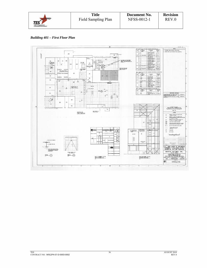
Title Field Sampling Plan
Document No. NFSS-0012-1
Revision REV.0
TES 56 AUGUST 2010 CONTRACT NO. W912P4-07-D-0003-0002 REV.0
Building 401 – First Floor Plan
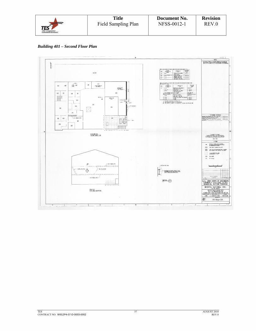
Title Field Sampling Plan
Document No. NFSS-0012-1
Revision REV.0
TES 57 AUGUST 2010 CONTRACT NO. W912P4-07-D-0003-0002 REV.0
Building 401 – Second Floor Plan

Title Field Sampling Plan
Document No. NFSS-0012-1
Revision REV.0
TES 58 AUGUST 2010 CONTRACT NO. W912P4-07-D-0003-0002 REV.0
Building 401 Decontamination Excavation Plan

Title Field Sampling Plan
Document No. NFSS-0012-1
Revision REV.0
TES 59 AUGUST 2010 CONTRACT NO. W912P4-07-D-0003-0002 REV.0
Attachment 2 MEMORANDUM
To: Luke Servedio
Phill Malich
From: Elizabeth Langille, CHP
Date: May 17, 2010
SUBJECT: NFSS BUILDING 401- REVIEW OF PREVIOUS ANALYSES TO ESTABLISH UNRESTRICTED RELEASE CRITERIA FOR SURVEYS
cc: Amanda Moore
SUMMARY
This memo provides the basis for the surface contamination release limits to be used to segregate radiological waste during the demolition of Building 401 at the Niagara Falls Storage Site in Lewiston, NY. The limits were determined using Regulatory Guide 1.86 acceptable surface contamination levels, for the radionuclide mixture seen in representative samples from Building 401.
Bldg 401 Surface Contamination Limits
Alpha average contamination (total): 2,000 dpm/100cm2
Alpha removable contamination: 200 dpm/100cm2
Beta average contamination (total): 5,000 dpm/100cm2
Beta removable contamination: 500 dpm/1002

Title Field Sampling Plan
Document No. NFSS-0012-1
Revision REV.0
TES 60 AUGUST 2010 CONTRACT NO. W912P4-07-D-0003-0002 REV.0
These limits will be described in the Field Sampling Plan (FSP) for performing beta scans, static beta measurements, static alpha measurements, and smears for removable
alpha and beta contamination.6
EVALUATION
The task order scope of work (SOW) for the NFSS Building 401 demolition (Reference 1) specifies in Section 3.6.1 that demolition debris and material with radiological surface contamination levels exceeding the unrestricted release criteria (assumed to be the NRC Reg Guide 1.86 criteria or as otherwise required by local, state, and federal regulations)
will for the purpose of this project, be considered radiologically contaminated materials.7
To determine the criteria in Reg Guide 1.86 that will be applied to the Building 401 surfaces, I reviewed previous surveys (referenced in Attachment 2 to the SOW) and the drain radionuclide analysis results in Attachment 3 to the SOW. Only sampling and analysis results within the building were used. Soil samples outside and below the building surface are not representative of the mixture of contaminants within the building and were not used.
The residual radioactivity, remaining in the drains and on I beams, is predominantly uranium in a natural uranium mixture. Elevated Th-230 was found in a pipe that was removed from the ceiling of Room 102 (Unique Identification Number 102-A), the activity in the pipe is noted to be different from the mixture seen in other samples of residual surface contamination in Building 401. The attached tables show the results for samples that showed elevated activity; only radionuclides that were detected above the method detection level (MDL) are shown.
The acceptable alpha surface contamination limit was calculated based on the radionuclide mix in each of the individual samples with total activity in excess of 25 pCi/g using the equation below. Where fi is the fraction of radionuclide “i” in the alpha
6 Alpha scans will not be performed. Uranium can be effectively detected using
beta scanning. 7 Reg Guide 1.86 criteria provides the same surface contamination levels as EM
385-1-80, USACE Radiation Protection Manual. The Reg Guide 1.86 criteria is noted to be more restrictive than New York State Department of Labor Part 38 - Ionizing Radiation Protection, Section 38.23 - Vacating Installations and Property, Table 5 - Acceptable Surface Contamination Levels
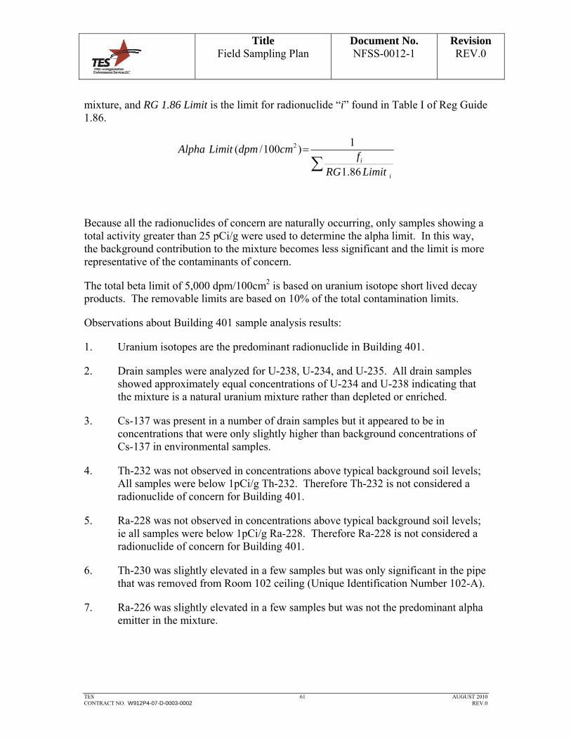
Title Field Sampling Plan
Document No. NFSS-0012-1
Revision REV.0
TES 61 AUGUST 2010 CONTRACT NO. W912P4-07-D-0003-0002 REV.0
mixture, and RG 1.86 Limit is the limit for radionuclide “i” found in Table I of Reg Guide 1.86.
i
i
LimitRG
fcmdpmLimitAlpha
86.1
1)100/( 2
Because all the radionuclides of concern are naturally occurring, only samples showing a total activity greater than 25 pCi/g were used to determine the alpha limit. In this way, the background contribution to the mixture becomes less significant and the limit is more representative of the contaminants of concern.
The total beta limit of 5,000 dpm/100cm2 is based on uranium isotope short lived decay products. The removable limits are based on 10% of the total contamination limits.
Observations about Building 401 sample analysis results:
1. Uranium isotopes are the predominant radionuclide in Building 401.
2. Drain samples were analyzed for U-238, U-234, and U-235. All drain samples showed approximately equal concentrations of U-234 and U-238 indicating that the mixture is a natural uranium mixture rather than depleted or enriched.
3. Cs-137 was present in a number of drain samples but it appeared to be in concentrations that were only slightly higher than background concentrations of Cs-137 in environmental samples.
4. Th-232 was not observed in concentrations above typical background soil levels; All samples were below 1pCi/g Th-232. Therefore Th-232 is not considered a radionuclide of concern for Building 401.
5. Ra-228 was not observed in concentrations above typical background soil levels; ie all samples were below 1pCi/g Ra-228. Therefore Ra-228 is not considered a radionuclide of concern for Building 401.
6. Th-230 was slightly elevated in a few samples but was only significant in the pipe that was removed from Room 102 ceiling (Unique Identification Number 102-A).
7. Ra-226 was slightly elevated in a few samples but was not the predominant alpha emitter in the mixture.
Title Field Sampling Plan
Document No. NFSS-0012-1
Revision REV.0
TES 62 AUGUST 2010 CONTRACT NO. W912P4-07-D-0003-0002 REV.0
ATTACHMENTS
1. Evaluation of Sample Results
REFERENCES
1. USNRC, Regulatory Guide 1.86, Termination of Operating Licenses for Nuclear Reactors, June 1974.
2. New York State Department of Labor, Part 38, Ionizing Radiation Protection, Section 38.23, Vacating Installations and Property.
3. U.S. Army Corps of Engineers, EM 385-1-80, Radiation Protection Manual, May 30, 1997.
4. ORISE, Radiological Survey of Buildings 401, 403, and the Hittman Building,
Niagara Falls Storage Site, Lewiston, NY.
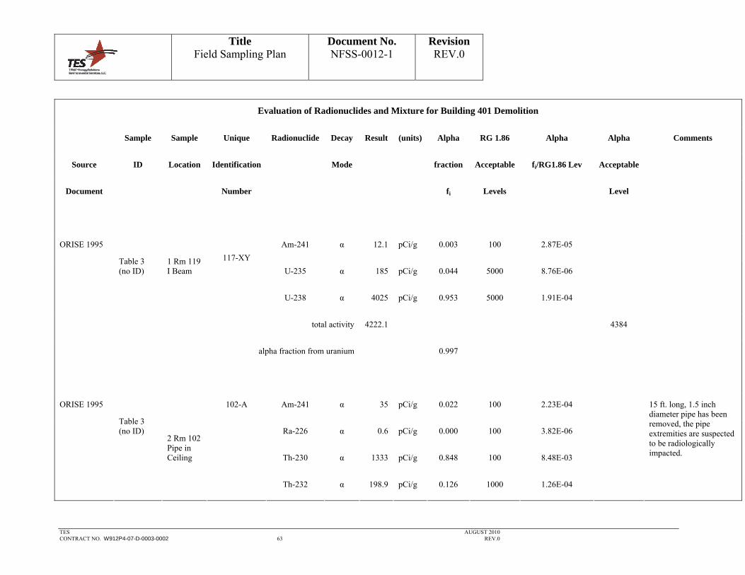
Title Field Sampling Plan
Document No. NFSS-0012-1
Revision REV.0
TES AUGUST 2010
CONTRACT NO. W912P4-07-D-0003-0002 63 REV.0
Evaluation of Radionuclides and Mixture for Building 401 Demolition
Sample Sample Unique Radionuclide Decay Result (units) Alpha RG 1.86 Alpha Alpha Comments
Source ID Location Identification Mode fraction Acceptable fi/RG1.86 Lev Acceptable
Document Number fi Levels Level
ORISE 1995 Am-241 α 12.1 pCi/g 0.003 100 2.87E-05
Table 3 (no ID)
1 Rm 119 I Beam
117-XY
U-235 α 185 pCi/g 0.044 5000 8.76E-06
U-238 α 4025 pCi/g 0.953 5000 1.91E-04
total activity 4222.1 4384
alpha fraction from uranium 0.997
ORISE 1995 102-A Am-241 α 35 pCi/g 0.022 100 2.23E-04
Table 3 (no ID) Ra-226 α 0.6 pCi/g 0.000 100 3.82E-06
2 Rm 102 Pipe in Ceiling Th-230 α 1333 pCi/g 0.848 100 8.48E-03
Th-232 α 198.9 pCi/g 0.126 1000 1.26E-04
15 ft. long, 1.5 inch diameter pipe has been removed, the pipe extremities are suspected to be radiologically impacted.

Title Field Sampling Plan
Document No. NFSS-0012-1
Revision REV.0
TES AUGUST 2010
CONTRACT NO. W912P4-07-D-0003-0002 64 REV.0
Evaluation of Radionuclides and Mixture for Building 401 Demolition
Sample Sample Unique Radionuclide Decay Result (units) Alpha RG 1.86 Alpha Alpha Comments
Source ID Location Identification Mode fraction Acceptable fi/RG1.86 Lev Acceptable
Document Number fi Levels Level
U-238 α 4.9 pCi/g 0.003 5000 6.23E-07
total activity 1572.4 113
ORISE 1995 Ra-226 α 0.6 pCi/g 0.042 100 4.20E-04
Table 3 (no ID) Th-232 α 1.3 pCi/g 0.091 1000 9.09E-05
3 Rm 121 drain?
Or floor trench? U-235 α 1.1 pCi/g 0.077 5000 1.54E-05
U-238 α 11.3 pCi/g 0.790 5000 1.58E-04
Total Activity is less than 25 pCi/g and therefor not used in the determination of the Alpha Limit
total activity 14.3
alpha fraction from uranium 0.867
ORISE 1995 Table 3 4 Rm 122
122-J Cs-137 α 0.2 pCi/g 0.006 5000 1.20E-06
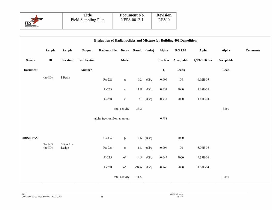
Title Field Sampling Plan
Document No. NFSS-0012-1
Revision REV.0
TES AUGUST 2010
CONTRACT NO. W912P4-07-D-0003-0002 65 REV.0
Evaluation of Radionuclides and Mixture for Building 401 Demolition
Sample Sample Unique Radionuclide Decay Result (units) Alpha RG 1.86 Alpha Alpha Comments
Source ID Location Identification Mode fraction Acceptable fi/RG1.86 Lev Acceptable
Document Number fi Levels Level
(no ID) I Beam
Ra-226 α 0.2 pCi/g 0.006 100 6.02E-05
U-235 α 1.8 pCi/g 0.054 5000 1.08E-05
U-238 α 31 pCi/g 0.934 5000 1.87E-04
total activity 33.2 3860
alpha fraction from uranium 0.988
ORISE 1995 Cs-137 β 0.6 pCi/g 5000
Table 3 (no ID)
5 Rm 217 Ledge Ra-226 α 1.8 pCi/g 0.006 100 5.79E-05
U-235 α* 14.5 pCi/g 0.047 5000 9.33E-06
U-238 α* 294.6 pCi/g 0.948 5000 1.90E-04
total activity 311.5 3895

Title Field Sampling Plan
Document No. NFSS-0012-1
Revision REV.0
TES AUGUST 2010
CONTRACT NO. W912P4-07-D-0003-0002 66 REV.0
Evaluation of Radionuclides and Mixture for Building 401 Demolition
Sample Sample Unique Radionuclide Decay Result (units) Alpha RG 1.86 Alpha Alpha Comments
Source ID Location Identification Mode fraction Acceptable fi/RG1.86 Lev Acceptable
Document Number fi Levels Level
total alpha activity 310.9
alpha fraction from uranium 0.994
Attachment 3 Cs-137 β 0.461 pCi/g 5000 0.00E+00
Ra-228 β 0.343 pCi/g 100 0.00E+00
DRAIN03-S-3705
Drain 3 sediment
(0.5')
Th-228 α 0.365 pCi/g 0.006 100 5.67E-05
Th-230 α 1.84 pCi/g 0.029 100 2.86E-04
Th-232 α* 0.469 pCi/g 0.007 1000 7.29E-06
U-233/234 α 26.2 pCi/g 0.407 5000 8.14E-05
U-235 α* 6.99 pCi/g 0.109 5000 2.17E-05
U-238 α* 28.5 pCi/g 0.443 5000 8.86E-05

Title Field Sampling Plan
Document No. NFSS-0012-1
Revision REV.0
TES AUGUST 2010
CONTRACT NO. W912P4-07-D-0003-0002 67 REV.0
Evaluation of Radionuclides and Mixture for Building 401 Demolition
Sample Sample Unique Radionuclide Decay Result (units) Alpha RG 1.86 Alpha Alpha Comments
Source ID Location Identification Mode fraction Acceptable fi/RG1.86 Lev Acceptable
Document Number fi Levels Level
total activity 65.2 1847
total alpha activity 64.4
alpha fraction from uranium 0.958
Attachment 3 Ra-226 α 4.29 pCi/L 0.029 100 2.88E-04
DRAIN03-W-3704
Drain 3 water Th-230 α 4.92 pCi/L 0.033 100 3.30E-04
Th-232 α* 0.673 pCi/L 0.005 1000 4.52E-06
U-233/234 α 58.7 pCi/L 0.394 5000 7.89E-05
U-235/236 α* 16.8 pCi/L 0.113 5000 2.26E-05
U-238 α* 63.5 pCi/L 0.427 5000 8.53E-05
total activity 148.9 1235

Title Field Sampling Plan
Document No. NFSS-0012-1
Revision REV.0
TES AUGUST 2010
CONTRACT NO. W912P4-07-D-0003-0002 68 REV.0
Evaluation of Radionuclides and Mixture for Building 401 Demolition
Sample Sample Unique Radionuclide Decay Result (units) Alpha RG 1.86 Alpha Alpha Comments
Source ID Location Identification Mode fraction Acceptable fi/RG1.86 Lev Acceptable
Document Number fi Levels Level
alpha fraction from uranium 0.934
Attachment 3 Ra-226 α 1.04 pCi/g 100
DRAIN04-S-3707
Ra-228 β 0.533 pCi/g 100
Drain 4 sediment
(0.5')
Th-230 α 2.18 pCi/g 100
Th-232 α 0.656 pCi/g 1000
U-233/234 α 7.42 pCi/g 5000
U-235/236 α* 1.36 pCi/g 5000
U-238 α* 6.42 pCi/g 5000
Total Activity is less than 25 pCi/g and therefor not used in the determination of the Alpha Limit
total activity 19.6

Title Field Sampling Plan
Document No. NFSS-0012-1
Revision REV.0
TES AUGUST 2010
CONTRACT NO. W912P4-07-D-0003-0002 69 REV.0
Evaluation of Radionuclides and Mixture for Building 401 Demolition
Sample Sample Unique Radionuclide Decay Result (units) Alpha RG 1.86 Alpha Alpha Comments
Source ID Location Identification Mode fraction Acceptable fi/RG1.86 Lev Acceptable
Document Number fi Levels Level
Attachment 3 Cs-137 β 0.0973 pCi/g 5000
DRAIN05-S-3709
Ra-226 α 0.719 pCi/g 100
Drain 5 sediment
(0.5')
Ra-228 β 0.196 pCi/g 100
Th-228 α 0.2 pCi/g 100
Th-230 α 1.24 pCi/g 100
U-233/234 α 2.24 pCi/g 5000
U-235/236 α* 0.222 pCi/g 5000
U-238 α* 2.05 pCi/g 5000
Total Activity is less than 25 pCi/g and therefor not used in the determination of the Alpha Limit
total activity 7.0
Attachment 3 DRAIN06- Drain 6 sediment
Cs-137 β 0.29 pCi/g 5000 Total Activity is less than 25 pCi/g and therefor not

Title Field Sampling Plan
Document No. NFSS-0012-1
Revision REV.0
TES AUGUST 2010
CONTRACT NO. W912P4-07-D-0003-0002 70 REV.0
Evaluation of Radionuclides and Mixture for Building 401 Demolition
Sample Sample Unique Radionuclide Decay Result (units) Alpha RG 1.86 Alpha Alpha Comments
Source ID Location Identification Mode fraction Acceptable fi/RG1.86 Lev Acceptable
Document Number fi Levels Level
S-3711
Ra-226 α 1.2 pCi/g 100
(0.5')
Ra-228 β 0.321 pCi/g 100
Th-228 α 0.542 pCi/g 100
Th-230 α 4.32 pCi/g 100
Th-232 α* 0.235 pCi/g 1000
U-233/234 α 5.73 pCi/g 5000
U-235/236 α* 2.01 pCi/g 5000
U-238 α* 5.3 pCi/g 5000
total activity 19.9
used in the determination of the Alpha Limit
Attachment 3 DRAIN06- Drain 6 Cs-137 β 2.12 pCi/L 5000

Title Field Sampling Plan
Document No. NFSS-0012-1
Revision REV.0
TES AUGUST 2010
CONTRACT NO. W912P4-07-D-0003-0002 71 REV.0
Evaluation of Radionuclides and Mixture for Building 401 Demolition
Sample Sample Unique Radionuclide Decay Result (units) Alpha RG 1.86 Alpha Alpha Comments
Source ID Location Identification Mode fraction Acceptable fi/RG1.86 Lev Acceptable
Document Number fi Levels Level
W-3710 water
Ra-226 α 1.13 pCi/L 0.034 100 3.40E-04
Th-228 α 0.559 pCi/L 0.017 100 1.68E-04
Th-230 α 2.76 pCi/L 0.083 100 8.31E-04
U-233/234 α 13 pCi/L 0.391 5000 7.83E-05
U-235/236 α* 1.77 pCi/L 0.053 5000 1.07E-05
U-238 α* 14 pCi/L 0.421 5000 8.43E-05
total activity 35.3 661
total alpha activity 33.2
alpha fraction from uranium 0.866
Attachment 3 DRAIN07- Drain 7 sediment
Cs-137 β 0.223 pCi/g 5000
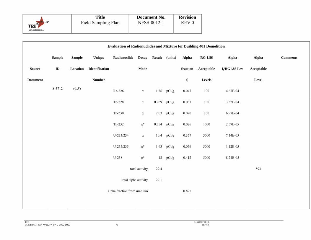
Title Field Sampling Plan
Document No. NFSS-0012-1
Revision REV.0
TES AUGUST 2010
CONTRACT NO. W912P4-07-D-0003-0002 72 REV.0
Evaluation of Radionuclides and Mixture for Building 401 Demolition
Sample Sample Unique Radionuclide Decay Result (units) Alpha RG 1.86 Alpha Alpha Comments
Source ID Location Identification Mode fraction Acceptable fi/RG1.86 Lev Acceptable
Document Number fi Levels Level
S-3712
Ra-226 α 1.36 pCi/g 0.047 100 4.67E-04
(0.5')
Th-228 α 0.969 pCi/g 0.033 100 3.32E-04
Th-230 α 2.03 pCi/g 0.070 100 6.97E-04
Th-232 α* 0.754 pCi/g 0.026 1000 2.59E-05
U-233/234 α 10.4 pCi/g 0.357 5000 7.14E-05
U-235/235 α* 1.63 pCi/g 0.056 5000 1.12E-05
U-238 α* 12 pCi/g 0.412 5000 8.24E-05
total activity 29.4 593
total alpha activity 29.1
alpha fraction from uranium 0.825
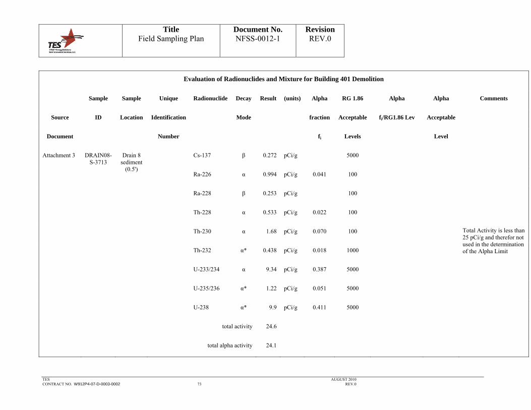
Title Field Sampling Plan
Document No. NFSS-0012-1
Revision REV.0
TES AUGUST 2010
CONTRACT NO. W912P4-07-D-0003-0002 73 REV.0
Evaluation of Radionuclides and Mixture for Building 401 Demolition
Sample Sample Unique Radionuclide Decay Result (units) Alpha RG 1.86 Alpha Alpha Comments
Source ID Location Identification Mode fraction Acceptable fi/RG1.86 Lev Acceptable
Document Number fi Levels Level
Attachment 3 Cs-137 β 0.272 pCi/g 5000
DRAIN08-S-3713
Ra-226 α 0.994 pCi/g 0.041 100
Drain 8 sediment
(0.5')
Ra-228 β 0.253 pCi/g 100
Th-228 α 0.533 pCi/g 0.022 100
Th-230 α 1.68 pCi/g 0.070 100
Th-232 α* 0.438 pCi/g 0.018 1000
U-233/234 α 9.34 pCi/g 0.387 5000
U-235/236 α* 1.22 pCi/g 0.051 5000
U-238 α* 9.9 pCi/g 0.411 5000
total activity 24.6
Total Activity is less than 25 pCi/g and therefor not used in the determination of the Alpha Limit
total alpha activity 24.1
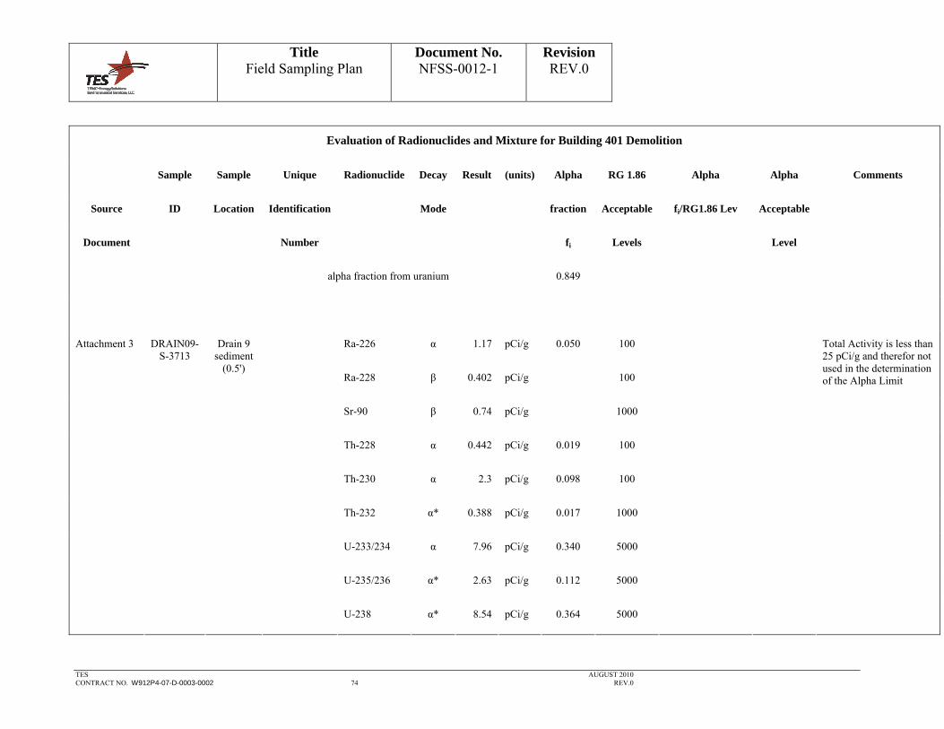
Title Field Sampling Plan
Document No. NFSS-0012-1
Revision REV.0
TES AUGUST 2010
CONTRACT NO. W912P4-07-D-0003-0002 74 REV.0
Evaluation of Radionuclides and Mixture for Building 401 Demolition
Sample Sample Unique Radionuclide Decay Result (units) Alpha RG 1.86 Alpha Alpha Comments
Source ID Location Identification Mode fraction Acceptable fi/RG1.86 Lev Acceptable
Document Number fi Levels Level
alpha fraction from uranium 0.849
Attachment 3 Ra-226 α 1.17 pCi/g 0.050 100
DRAIN09-S-3713
Ra-228 β 0.402 pCi/g 100
Drain 9 sediment
(0.5')
Sr-90 β 0.74 pCi/g 1000
Th-228 α 0.442 pCi/g 0.019 100
Th-230 α 2.3 pCi/g 0.098 100
Th-232 α* 0.388 pCi/g 0.017 1000
U-233/234 α 7.96 pCi/g 0.340 5000
U-235/236 α* 2.63 pCi/g 0.112 5000
U-238 α* 8.54 pCi/g 0.364 5000
Total Activity is less than 25 pCi/g and therefor not used in the determination of the Alpha Limit

Title Field Sampling Plan
Document No. NFSS-0012-1
Revision REV.0
TES AUGUST 2010
CONTRACT NO. W912P4-07-D-0003-0002 75 REV.0
Evaluation of Radionuclides and Mixture for Building 401 Demolition
Sample Sample Unique Radionuclide Decay Result (units) Alpha RG 1.86 Alpha Alpha Comments
Source ID Location Identification Mode fraction Acceptable fi/RG1.86 Lev Acceptable
Document Number fi Levels Level
total activity 24.6
total alpha activity 23.4
alpha fraction from uranium 0.816
Attachment 3 Cs-137 β 0.245 pCi/g 5000
DRAIN10-S-3715
Ra-226 α 1.28 pCi/g 100
Drain 10 sediment
(0.5')
Th-228 α 0.882 pCi/g 100
Th-230 α 2.61 pCi/g 100
Th-232 α* 0.382 pCi/g 1000
U-233/234 α 6.8 pCi/g 5000
U-235/236 α* 0.468 pCi/g 5000
Total Activity is less than 25 pCi/g and therefor not used in the determination of the Alpha Limit

Title Field Sampling Plan
Document No. NFSS-0012-1
Revision REV.0
TES AUGUST 2010
CONTRACT NO. W912P4-07-D-0003-0002 76 REV.0
Evaluation of Radionuclides and Mixture for Building 401 Demolition
Sample Sample Unique Radionuclide Decay Result (units) Alpha RG 1.86 Alpha Alpha Comments
Source ID Location Identification Mode fraction Acceptable fi/RG1.86 Lev Acceptable
Document Number fi Levels Level
U-238 α* 7.79 pCi/g 5000
total activity 20.5
Average alpha limit (dpm/100cm2) 2074
Notes
Sample Location:
ORISE 1995, Radiological Survey of buildings 401, 403, and the Hittman Building
Niagara Falls Storage Site, Lewiston, New York, T.J. Vitkus
Attachment 3, Attachment 3 to the SOW for Demolition of building 401 FUSRAP - NFSS
Decay Mode:
α, alpha
α*, alpha but short lived particulate progeny decays by beta and can be readily detected using beta survey techniques
β, beta

Title Field Sampling Plan
Document No. NFSS-0012-1
Revision REV.0
TES AUGUST 2010
CONTRACT NO. W912P4-07-D-0003-0002 77 REV.0
Attachment 3
Fifty-Six Services, Inc.
Asbestos Survey Procedure
Title Field Sampling Plan
Document No. NFSS-0012-1
Revision REV.0
TES AUGUST 2010
CONTRACT NO. W912P4-07-D-0003-0002 78 REV.0
ASBESTOS SURVEY FIELD SURVEY PROCEDURES AND SAMPLE ANALYSIS METHODS
Guidelines used for the asbestos inspection were established by the Environmental Protection Agency (EPA) in the Guidance for Controlling Asbestos Containing Materials in Buildings, Office of Pesticides and Toxic Substances, Doc 560/5-85-024, and 40 CFR Part 763, Asbestos Hazard Emergency Response Act (AHERA).
Field information is organized in accordance with the AHERA methodology of homogenous area (HA). During the survey, reasonable effort are made to identify all locations and types of ACM materials associated with the scope of work. Sampling has included multiple samples of the same materials chosen at random. However, due to inconsistencies of a manufacturer's processes and the contractor’s installation methods, materials of similar construction may contain various amounts of asbestos. Furthermore, some materials that were not originally specified to contain asbestos may in fact contain this mineral. For example, cemantatious pipe insulation and plaster were frequently mixed with asbestos at the construction site for ease of application. Locating all asbestos materials can only be definitively achieved by conducting exploratory demolition and sampling every section of pipe insulation, fitting or valve covering, fireproofing, and other suspect ACM.
Bulk samples of suspect ACM were analyzed using polarized light microscopy (PLM) coupled with dispersion staining, as described in 40 CFR Part 763 and the National Emissions Standard for Hazardous Air Pollutants (NESHAPS). NESHAPS is the standard industry protocol for the determination of asbestos in building materials. A suspect material is immersed in a solution of known refractive index and subjected to illumination by polarized light. The color displays that result are compared to a standardized atlas whereby the specific variety of asbestos is determined. It should also be recognized that PLM is primarily a qualitative identification method whereby asbestos percentage, if any, is estimated. While EPA and New York State regulations governing ACM consider materials containing greater then 1-percent as asbestos, accurately quantifying asbestos content below 5-percent has been shown to be unreliable.
The New York State Department of Health has revised the PLM Stratified Point Counting Method. The new method, "Polarized Light Microscopy Methods for Identifying and Quantifying Asbestos in Bulk Samples" can be found as item 198.1 in the Environmental Laboratory Approval program (ELAP) Certification manual. The method specifies a procedure of analysis for bulk samples that fall into the category of "Non-friable Organically Bound" (NOB). This category includes any sample in a flexible to rigid asphalt or vinyl matrix (floor tiles, mastic, roofing shingles, roofing felt, etc.). Additional materials that may fall into this category are textured paints and stucco, pipe valve and joint packing, and a variety of other applications. These samples must be “ashed” in a muffle furnace at 480-degrees Celsius (to remove organic matrix), treated with acid (to remove any mineral carbonate), and filtered through a 0.4-micron filter before being analyzed by PLM. The sample must be weighted between each of these steps to track the percent loss of organic matrix.
Title Field Sampling Plan
Document No. NFSS-0012-1
Revision REV.0
TES AUGUST 2010
CONTRACT NO. W912P4-07-D-0003-0002 79 REV.0
ELAP has determined that analysis of NOB materials is not reliably performed by PLM. Therefore, if PLM yields results of 1-percent asbestos or less, the result must be confirmed by TEM. Bulk samples that undergo TEM analysis use the sample reduction methodology stated above for NOB analysis by PLM. ELAP certified laboratories must include the following statement with their PLM analysis results for each “negative” (1-percent or less asbestos) NOB sample: "Polarized-light microscopy is not consistently reliable in detecting asbestos in floor coverings and similar non-friable organically bound materials. Before this material can be considered or treated as non-ACM, confirmation must be made by quantitative transmission electron microscopy".
All samples were initially analyzed by Polarized Light Microscopy. Samples which yielded a negative PLM result and which are classified as a "non-friable" material, were then re-analyzed utilizing Transmission Electron Microscopy methodology described above. The laboratory performing both these analysis procedures was Paradigm Environmental, Inc. located at 1815 Love Rd, Grand Island, New York. Paradigm is accredited with the following agencies:
National Voluntary Laboratory Accreditation Program New York State Environmental Laboratory Approval Program