san migration guide
TRANSCRIPT
Publication Number: 53-0000360-02Publication Date: July 11, 2003
SAN Migration GuideVersion 1.1

Copyright © 2003, Brocade Communications Systems, Incorporated.
ALL RIGHTS RESERVED. Publication Number: 53-0000360-02
BROCADE, the Brocade B weave logo, Brocade: the Intelligent Platform for Networking Storage, SilkWorm, and SilkWorm Express, are trademarks or registered trademarks of Brocade Communications Systems, Inc. or its subsidiaries in the United States and/or in other countries. All other brands, products, or service names are or may be trademarks or service marks of, and are used to identify, products or services of their respective owners.
Notice: The information in this document is provided “AS IS,” without warranty of any kind, including, without limitation, any implied warranty of merchantability, noninfringement or fitness for a particular purpose. Disclosure of information in this material in no way grants a recipient any rights under Brocade's patents, copyrights, trade secrets or other intellectual property rights. Brocade reserves the right to make changes to this document at any time, without notice, and assumes no responsibility for its use.
The authors and Brocade Communications Systems, Inc. shall have no liability or responsibility to any person or entity with respect to any loss, cost, liability, or damages arising from the information contained in this book or the computer programs that accompany it.
Notice: The product described by this document may contain “open source” software covered by the GNU General Public License or other open source license agreements. To find-out which open source software is included in Brocade products, view the licensing terms applicable to the open source software, and obtain a copy of the programming source code, please visit http://www.brocade.com/support/oscd.
Export of technical data contained in this document may require an export license from the United States Government.
Brocade Communications Systems, IncorporatedCorporate Headquarters1745 Technology DriveSan Jose, CA 95110T: (408) 487-8000F: (408) 487-8101Email: [email protected]
Asia-Pacific HeadquartersShiroyama JT Trust Tower 36th Floor4-3-1 Toranomon, Minato-kuTokyo, Japan 105-6036T: +81 35402 5300F: +81 35402 5399Email: [email protected]
European Headquarters29, route de l’AeroportCase Postale 105CH-1211 Geneva 15,SwitzerlandT: +41 22 799 56 40F: +41 22 799 56 41Email: [email protected]
Latin America Headquarters5201 Blue Lagoon DriveMiami, FL 33126T: (305) 716-4165Email: [email protected]

Document HistoryThe table below lists all versions of the SAN Migration Guide.
Document Version
Publication Number
Publication Date
Type of Modification/Change
v1.0 53-0000360-01 3/28/2003 New publication.
v1.1 53-0000360-02 7/11/2003 Addition of Case Studies (Chapter 6), Migration from McData (Chapter 7), and Firmware Download procedure (Appendix B).

Table of Contents
Preface
Chapter 1 About Switch MigrationIntroduction. . . . . . . . . . . . . . . . . . . . . . . . . . . . . . . . . . . . . . . . . . . . . . . . . . . 1-1
Fabric Migration Process Overview . . . . . . . . . . . . . . . . . . . . . . . . . . . . . . . . 1-2
Chapter 2 Assessing the Target SANApplication Environment . . . . . . . . . . . . . . . . . . . . . . . . . . . . . . . . . . . . . . . . 2-1
Single Fabric vs. Redundant Fabric . . . . . . . . . . . . . . . . . . . . . . . . . . . . . . . . 2-3
Planning a Topology Change . . . . . . . . . . . . . . . . . . . . . . . . . . . . . . . . . . 2-4
Auto Negotiation. . . . . . . . . . . . . . . . . . . . . . . . . . . . . . . . . . . . . . . . . . . . 2-4
Trunking . . . . . . . . . . . . . . . . . . . . . . . . . . . . . . . . . . . . . . . . . . . . . . . . . . 2-4
Zoning Strategy. . . . . . . . . . . . . . . . . . . . . . . . . . . . . . . . . . . . . . . . . . . . . 2-5
Understanding the Core PID Format . . . . . . . . . . . . . . . . . . . . . . . . . . . . . . . 2-5
Impact to Zoning. . . . . . . . . . . . . . . . . . . . . . . . . . . . . . . . . . . . . . . . . . . . 2-5
Core PID Format Change . . . . . . . . . . . . . . . . . . . . . . . . . . . . . . . . . . . . . 2-6
Fabric OS Upgrade . . . . . . . . . . . . . . . . . . . . . . . . . . . . . . . . . . . . . . . . . . 2-6
Host Re-boot Consideration . . . . . . . . . . . . . . . . . . . . . . . . . . . . . . . . . . . . . . 2-6
Persistent Binding Update . . . . . . . . . . . . . . . . . . . . . . . . . . . . . . . . . . . . 2-7
When Host Reboot Is Not An Option. . . . . . . . . . . . . . . . . . . . . . . . . . . . 2-7
Logistics . . . . . . . . . . . . . . . . . . . . . . . . . . . . . . . . . . . . . . . . . . . . . . . . . . . . . 2-8
Rack Space Availability . . . . . . . . . . . . . . . . . . . . . . . . . . . . . . . . . . . . . . 2-8
Cabling . . . . . . . . . . . . . . . . . . . . . . . . . . . . . . . . . . . . . . . . . . . . . . . . . . . 2-9
Small Form Factor Pluggable . . . . . . . . . . . . . . . . . . . . . . . . . . . . . . . . . . 2-10
Replacing an Existing Switch . . . . . . . . . . . . . . . . . . . . . . . . . . . . . . . . . . . . . 2-10
SAN Migration Guide v

Chapter 3 Developing a Migration StrategySingle Fabric Online Migration Qualification . . . . . . . . . . . . . . . . . . . . . . . . 3-3
Redundant Fabric Online Migration Qualification. . . . . . . . . . . . . . . . . . . . . 3-3
Offline Fabric Migration Qualification. . . . . . . . . . . . . . . . . . . . . . . . . . . . . . 3-4
Readiness Checklist . . . . . . . . . . . . . . . . . . . . . . . . . . . . . . . . . . . . . . . . . . . . 3-5
Chapter 4 Migration ProcedureSingle Fabric Online Migration . . . . . . . . . . . . . . . . . . . . . . . . . . . . . . . . . . . 4-2
Single Fabric Online Migration Procedure . . . . . . . . . . . . . . . . . . . . . . . . 4-3
Offline Fabric Migration. . . . . . . . . . . . . . . . . . . . . . . . . . . . . . . . . . . . . . . . . 4-5
Incremental Fabric Upgrade Procedure . . . . . . . . . . . . . . . . . . . . . . . . . . 4-6
Fabric Replacement Procedure . . . . . . . . . . . . . . . . . . . . . . . . . . . . . . . . . 4-7
Redundant Fabric Online Migration . . . . . . . . . . . . . . . . . . . . . . . . . . . . . . . . 4-9
Redundant Fabric Online Migration Procedure . . . . . . . . . . . . . . . . . . . . 4-10
Chapter 5 Prepare to MigrateCore PID Upgrade Procedure . . . . . . . . . . . . . . . . . . . . . . . . . . . . . . . . . . . . . 5-1
Port ID Persistent Binding Procedure . . . . . . . . . . . . . . . . . . . . . . . . . . . . . . . 5-3
2 Gbit/sec Switch Preparation. . . . . . . . . . . . . . . . . . . . . . . . . . . . . . . . . . . . . 5-5
Assigning IP an Address. . . . . . . . . . . . . . . . . . . . . . . . . . . . . . . . . . . . . . 5-6
Switch Configuration Parameters Setup . . . . . . . . . . . . . . . . . . . . . . . . . . 5-6
Propagating an Existing Zone Configuration . . . . . . . . . . . . . . . . . . . . . . 5-7
Verify 2 Gbit/sec Switch Parameters . . . . . . . . . . . . . . . . . . . . . . . . . . . . . . . 5-10
Chapter 6 Case StudiesTest Fabric Configuration Overview . . . . . . . . . . . . . . . . . . . . . . . . . . . . . . . 6-1
vi SAN Migration Guide
Assessing the Target SAN . . . . . . . . . . . . . . . . . . . . . . . . . . . . . . . . . . . . . . . 6-3
SAN Topology . . . . . . . . . . . . . . . . . . . . . . . . . . . . . . . . . . . . . . . . . . . . . 6-3
Host and Storage Port Connectivity Map via Fabric A and B . . . . . . . . . . . . . . . . . . . . . . . . . . . . . . . . . . . . . . . . . . 6-4
Zoning Implementation on Fabric A and B . . . . . . . . . . . . . . . . . . . . . . . 6-4
Host OS and Persistent Binding . . . . . . . . . . . . . . . . . . . . . . . . . . . . . . . . 6-5
Determining Fabric OS Upgrade and Core PID Format Change Requirements6-6
Planning for Topology Change or Enabling Trunking . . . . . . . . . . . . . . . 6-6
Checklist . . . . . . . . . . . . . . . . . . . . . . . . . . . . . . . . . . . . . . . . . . . . . . . . . . 6-6
Prepare to Migrate (Example Fabric B) . . . . . . . . . . . . . . . . . . . . . . . . . . . . . 6-7
Bring Fabric B Offline . . . . . . . . . . . . . . . . . . . . . . . . . . . . . . . . . . . . . . . 6-7
Fabric OS Compatibility Level. . . . . . . . . . . . . . . . . . . . . . . . . . . . . . . . . 6-10
Core PID Format Upgrade Procedure. . . . . . . . . . . . . . . . . . . . . . . . . . . . 6-11
Establishing Switch Replacement Order . . . . . . . . . . . . . . . . . . . . . . . . . 6-13
Zone Merge Strategy. . . . . . . . . . . . . . . . . . . . . . . . . . . . . . . . . . . . . . . . . 6-14
SilkWorm 3900 Switch Preparation . . . . . . . . . . . . . . . . . . . . . . . . . . . . . 6-14
Test Cases 1-6 . . . . . . . . . . . . . . . . . . . . . . . . . . . . . . . . . . . . . . . . . . . . . . . . . 6-21
Case 1: Direct Replacement of a 1 Gbit/sec Edge Switch Connecting Storage6-22
Case 2: Direct Replacement of a 1 Gbit/sec Core Switch with a SilkWorm 39006-26
Bringing Fabric B Online . . . . . . . . . . . . . . . . . . . . . . . . . . . . . . . . . . . . . 6-27
Case 3: Adding a New SilkWorm 3900 to Fabric B. . . . . . . . . . . . . . . . . 6-28
Case 4: Collapsing Two 1 Gbit/sec Lower Port Count Switches Providing Storage Connectivity into a Single SilkWorm 3900 . . . . . . . . . . . . . . . . . 6-30
Case 5: Collapsing Two 1 Gbit/sec Lower Port Count Switches Providing Host Connectivity into a Single SilkWorm 3900 . . . . . . . . . . . . . . . . . . . . . . . 6-41
Case 6: Replacing a Lower Port Count Core Switch with High Performance SilkWorm 12000 . . . . . . . . . . . . . . . . . . . . . . . . . . . . . . . . . . . . . . . . . . . . 6-44
Chapter 7 Migration Procedure from McData to Brocade FabricMigration from McData to Brocade Fabric . . . . . . . . . . . . . . . . . . . . . . . . . . 7-1
SAN Migration Guide vii

The Basic Steps for Migration from McData to Brocade . . . . . . . . . . . . . . . . 7-2
Step 1: Assessing System and Storage Configuration . . . . . . . . . . . . . . . 7-3
Step 2: Assessing McData Fabric Operating Parameters . . . . . . . . . . . . . 7-4
Step 3: Setup and Configuration of the Brocade Fabric . . . . . . . . . . . . . . 7-9
Step 4: Import McData Zoning to the Brocade Fabric . . . . . . . . . . . . . . . 7-12
Step 5: Moving Devices to the Brocade Fabric . . . . . . . . . . . . . . . . . . . . 7-17
Step 6: Restoring the Closed Path on the Brocade Fabric . . . . . . . . . . . . 7-21
Chapter A Operating System PlatformsSun Solaris-8. . . . . . . . . . . . . . . . . . . . . . . . . . . . . . . . . . . . . . . . . . . . . . . . . . A-1
IBM AIX 4.3. . . . . . . . . . . . . . . . . . . . . . . . . . . . . . . . . . . . . . . . . . . . . . . . . . A-5
HP-UX 11i . . . . . . . . . . . . . . . . . . . . . . . . . . . . . . . . . . . . . . . . . . . . . . . . . . . A-7
MS Windows 2000 Server . . . . . . . . . . . . . . . . . . . . . . . . . . . . . . . . . . . . . . . A-12
Chapter B Fabric OS Upgrade from 4.0.x TO 4.1.xUnderstanding the Upgrade Process . . . . . . . . . . . . . . . . . . . . . . . . . . . . . . . . B-1
Minimum Level of CP Hardware Requirement . . . . . . . . . . . . . . . . . . . . . . . B-2
Downloading Fabric OS . . . . . . . . . . . . . . . . . . . . . . . . . . . . . . . . . . . . . . . . . B-3
Fabric OS Downloading Procedure on the SilkWorm 12000. . . . . . . . . . . . . B-4
Upgrading to Fabric OS 4.1.0 from Fabric OS 4.0.0c or Lower . . . . . . . B-4
Upgrading to Fabric OS 4.1 from Fabric OS 4.0.0d or Greater . . . . . . . . B-9
Firmware Upgrade on a SilkWorm 3900 . . . . . . . . . . . . . . . . . . . . . . . . . . . . B-13
Verifying Switch Functionality . . . . . . . . . . . . . . . . . . . . . . . . . . . . . . . . . . . . B-14
Appendix C GlossaryTerms and Definitions. . . . . . . . . . . . . . . . . . . . . . . . . . . . . . . . . . . . . . . . . . . C-1
viii SAN Migration Guide

Preface
About This GuideThis guide provides comprehensive information to help you migrate your current 1 Gbit/sec Brocade SAN to high bandwidth and/or high port count SilkWorm switches. This guide was developed to help technical experts assess, plan, prepare and perform a migration. This guide can be used with the other product user manuals referenced or as a standalone document. A list of additional SAN resource reference materials is also included. The sections that follow provide:
• Scope of the document• Terms and Definitions used in this document• Related publications and Brocade reference material• Conventions used in this guide
Intended AudienceThis document is intended for use by systems administrators and technicians experienced with networking, Fibre Channel, and SAN technologies.
ScopeThe purpose of this document is to assist in planning a successful migration path that will either completely avoid or minimize the fabric disruption and downtime. The following issues are addressed:
• Minimizing or eliminating fabric operation and I/O interruption during migration• Understanding the current fabric environment• Impact to fabric operation impact• Core PID Format considerations• Operational requirements• Managing Hard zoning based on PID• Persistent bindings based on PID
The following is not included in the scope of this document:
• Fabric Manager• Third-party software• Case studies
SAN Migration Guide vii

Terms and DefinitionsTable 0-1 Key Terms and Definitions
Terms Definitions and impact
Core PID format The 24-bit Switch Fabric Port Identification (PID) also known as SID consists of Domain ID, Area and AL_PA fields.
Fabric One or more interconnected Fibre Channel switches. The term “Fabric” only refers to the interconnected switches, not to nodes or devices connected to the fabric.
Fabric build(BF)
The build fabric Switch Fabric Internal Link Service requests a non-disruptive configuration to the entire fabric. A BF process shall not cause the Domain ID list to be cleared. This preserves existing node port addresses and allows open exchanges to be completed. Impact: Fabric build is a non-disruptive process.
Fabric re-configuration (RCF)
Fabric reconfiguration is a disruptive fabric operation during which Domain IDs may change. If the Domain ID changes, all attached node ports must re-log in with the fabric and be assigned new N-Ports identifiers reflecting the change in Domain IDs.Impact: Reconfigure causes Class-n frames (1,2,3,4 or 6) to be discarded and class 1 connection to be abnormally removed.
Fabric Segmentation A fabric is unable to resolve the switch configuration parameters during the rebuild process with one or more switches, and may isolate them from the fabric, causing fabric segmentation. Impact: I/O operations are ceased only on those devices losing their access due to segmentation.
Fabric topology A topology is “the logical layout of the components of a computer system or network and their interconnections.” A fabric topology is the layout of the switches that form a fabric.
Incremental upgrade Replacing one switch at a time in an online fabric.
Offline Fabric A non-functional state of fabric unsuitable for I/O operation.
Online Fabric A functional stable state of a fabric performing reliable I/O fabric operations.
PID bindings Static mapping between physical and logical devices on a host accomplished via Port_ID (PID).
Redundant Fabric A SAN composed of two or more independent fabrics The multiple fabric architecture makes dual fabric SANs redundant.Impact: SAN topology configured to provide two or more alternate paths for high availability.
SAN A Storage Area Network (SAN) can consist of one or more related fabrics and the connected nodes.
SAN Architecture The overall design or structure of a storage area network solution. This includes one or more related fabrics, each of which has a topology. Other components may also be included, such as host, storage, and other SAN devices.
Single Fabric A SAN composed of a single fabric may be configured to provide one or more paths via different switches of the fabric. Impact: Offers no Protection at fabric level. All paths are closed when fabric is offline, completely stopping I/Os.
viii SAN Migration Guide
Manual Conventions
FormattingThe following table describes the formatting conventions that are used in this book:
Notes and GuidelinesThe following notices appear in this document:
Note: A note emphasizes important information or provides a reference to related information.
Guideline: A guideline provides a tip or a recommendation.
Convention Purpose
bold text • identifies GUI elements• identifies keywords/operands• identifies text to enter at the GUI or CLI
italic text • provides emphasis• identifies variables• identifies paths and internet addresses• identifies book titles and cross references
code text • identifies commands in line with text• identifies CLI output• identifies syntax examples
SAN Migration Guide ix

Related Publications
Brocade DocumentationThe following related publications are provided on the Brocade Documentation CD-ROM and on the Brocade Partner web site. To access Brocade Partner web site go to www.brocade.com and click on the partner login link. • Brocade Fabric OS documentation
- Brocade Fabric OS Procedures Guide- Brocade Fabric OS Reference
• Brocade Fabric OS optional features documentation- Brocade Performance Monitoring User's Guide- Brocade Zoning User's Guide- Brocade Web Tools User's Guide- Brocade Distributed Fabrics User's Guide- Brocade Fabric Watch User’s Guide- Brocade ISL Trunking User's Guide- Brocade Secure Fabric OS® User's Guide- Brocade QuickLoop User's Guide (v 3.1 only)
• Brocade Hardware documentation- Brocade SilkWorm 12000 Hardware Reference- Brocade SilkWorm 3900 Hardware Reference - Brocade SilkWorm 3800 Hardware Reference
Additional Resource InformationThe following related publications are provided on the Brocade Partner web site and are an excellent resource for additional information.
• SilkWorm 12000 Core Migration User’s Guide (publication number 53-0000477-02)• Core Switch PID Format Update Best Practices (publication Number 53-0001626-01)
x SAN Migration Guide

SAN Migration Guide
Chapter
1
About Switch Migration1.1. IntroductionBrocade’s high speed (2 Gbit/sec) SilkWorm 3800, 3900, and 12000 switches are enhanced with rich management, availability, and security features that are fundamental building blocks of today’s SAN. The benefits of upgrading an existing 1 Gbit/sec 2000 series switch to high bandwidth 2 Gbit/sec technology, or upgrading lower port count switches (such as the SilkWorm 2000 series, 3200, and 3800) to higher port count switches, are significant. One of the major advantages of using a Brocade switch fabric is backward compatibility across all Brocade platforms. New models of Brocade switches can be introduced in a seamless fashion into an existing environment while preserving the investment in existing switches.
Migrating from an existing operational SAN requires careful consideration to ensure a seamless migration with minimum or no impact to ongoing SAN operations. It is crucial to obtain a clear understanding of the existing SAN and application environment. This information is required to develop a successful migration strategy. With proper planning, an existing fabric can be replaced or incrementally upgraded with Brocade’s 2 Gbit/sec SilkWorm switches without adversely affecting fabric operations and I/O.
Table 1-1
Note: The migration procedures detailed in this document are applicable to both 1 Gbit/sec switches (SilkWorm 2000 series) and lower port count 2 Gbit/sec switches (SilkWorm 3800, 3200).
Migrating From TO 1 Gbit/sec 2000 SilkWorm Series Model Brocade Fabric OS V2.x
2 Gbit/sec SilkWorm 3800, 3900, 12000 Brocade Fabric OS V3.x/4.x
Low Port Count High Port Count
8, 16 port SilkWorm switch Brocade Fabric OS V2.x, V3.x
SilkWorm 3900/12000 Brocade Fabric OS V4.x
1-1

About Switch Migration1
1.2. Fabric Migration Process OverviewThe fabric migration process is outlined in Figure 1-1. This process is detailed in the following chapters, as indicated. Each chapter contains one or more flowcharts to identify the detail required as you assess, plan, prepare, and proceed with the migration.
Figure 1-1 SAN Migration Process Overview Flowchart
Assess the SANtargeted formigration
(Chapter 2)
Choose the rightmigration Strategy
to matchexpectations
Perform thenecessarymigration
pre-requisites(Chapter 5)
Migrate theswitches
(Chapter 4)
Validate 2 GbitSAN
Develop a planbased on the type
of migration(Chapter 3)
Is the planacceptable?
SAN MigrationPROCESS OVERVIEW
yes
No
SAN ArchitectureLogistics- Rack space. Power and CableHost rebooting considerationExisting Switch configuration
Single Fabric Online MigrationOffline Fabric MigrationRedundant Fabric Migration
Online or offline Migration
Prepare SAN to perform one or more ofthe following steps if required.FOS upgradeCore PID Format UpdatePersistent binding PID methodHost reboot
Schedule upgrade time
2 Gbit/sec switch preparation andMigrationZoning configuration update
Verify the functionality of the new2 Gbit/sec SANNo fabric segmentationZoning verificationSuccessful login of all attached devicesHost access to the device
1-2 SAN Migration Guide
SAN Migration Guide
Chapter
2
Assessing the Target SAN2.1. Application EnvironmentIt is important to have an understanding of the current application environment before attempting a migration. There is more than one way to proceed with the migration process depending on the current SAN architecture, fabric topology, size and number of active devices attached. The migration process is simple and straightforward on an offline fabric. However, an online migration in a single or redundant fabric requires careful evaluation of the currently deployed topology to plan for a methodical migration path.
The flowchart in Figure 2-1 on page 2-2 outlines the various aspects of a migration that need to be considered when developing migration strategy for a minimum interruption in fabric operation. This includes the following:
• Assessing the existing fabric topology • Single fabric vs. redundant fabric• Planning a topology change at the time of migration • The zone configuration export /modify strategy• Auto Negotiation setup considerations• Trunking setup considerations
• Assessing the existing fabric switch• Core PID change considerations• Fabric OS upgrade requirements• Listing the setup configuration parameters of the existing switch
• Host reboot considerations• PID static binding may require host reboot.• When upgrading HBA hardware to 2 Gbit/sec, host downtime is required• Alternatives to rebooting the host
• Logistic planning of hardware installation• Rack space requirements• Power requirements• Cable requirements
• The new 2 Gbit/sec switch preparation • Switch replacement considerations• Considerations when adding a switch to an existing fabric
2-1
Assessing the Target SAN2
Figure 2-1 Fabric Assessment Flowchart
Is FOSupgrade
required?
Enough rackspace ?
Enoughpower?
Is auto-negotiationsuf f icient ?
What istrunking
strategy ?
What is thezone import
strategy to the2 Gbit f abric?
Any otherconf iguration, parameters
update?
Fabric Assessment
Is there any topology
changeplanned ?
Any planto upgrade
HBA to2Gbit/sec?
Logistics(page 2-9)
Existing Fabric(page 2-3)
Existing FabricSw itch
(page 2-5)
Is CorePID changerequired?
New 2 Gbit/secSw itch
(page 2-10)
Host Reboot(page 2-7)
Is hosthba conf ig.f ilechanges? (PID
bindings)
Replacingor adding a2Gbit/secswitch?
Is Host reboot
acceptable ifrequired?
Name, IPDomain. setupconsideration
Necessarycablesready ?
= Critical items
2-2 SAN Migration Guide

Assessing the Target SAN 2
2.2. Single Fabric vs. Redundant FabricWhen planning a fabric migration it is important to consider possible fabric downtime or I/O interruptions. It is possible to migrate a redundant SAN, that is properly configured, with no interruption to I/O and without going offline. In contrast, a single fabric that does not utilize multi-pathing software may require an interruption of I/O or require the fabric to go offline.
Figure 2-2 SAN Architecture Diagram
Single Fabric Configuration
Redundant Fabric Configuration
Fabric-A Fabric-B
Host
Storage
Host
Storage
Host
Storage
Single Fabric, ResilientConfiguration
SAN Migration Guide 2-3
Assessing the Target SAN2
2.2.1. Planning a Topology ChangeConsidering a different topology for a high port count switch fabric, other than what is already in place, imposes additional requirements. A large fabric installation can benefit from a core/edge fabric topology, such as, introducing a SilkWorm 12000 as the Core switch and replacing existing edge switches with SilkWorm 3900s as edge switches. Proper planning is required to meet racking, powering, cabling and switch configuration requirements to minimize fabric downtime.
2.2.2. Auto NegotiationBrocade SilkWorm 2 Gbit/sec switches are fully capable of supporting both 1 Gbit/sec and 2 Gbit/sec transmission speeds. The individual switch ports can be set dynamically to a negotiated speed or they can be manually set to operate at a pre-determined speed. The switch ports, by default, are set for Auto negotiation. If the device fails to properly log in because of speed negotiation failure, consider manually setting the switch port to match the device supported speed.
Speed Negotiation related commands:
portCfgspeed - Configure the speed of a port to a specific level
switchCfgspeed - Configure all ports of the switch to a particular speed.
PortCfgShow - Display the current configuration of the ports
2.2.3. TrunkingTrunking is a 2 Gbit/sec switch feature that offers to increase the inter-switch link (ISL) bandwidth up to 8 Gbit/sec, depending on the number of configured ISLs in trunk. Each ASIC supports four fabric ports, therefore, a trunk can be constructed using two or more ports with in a single ASIC. The trunking group is identified by the trunk master that represents the entire group. The rest of the group members are referred to as slave links that help the trunking master direct traffic across ISLs, allowing efficient and balanced in-order communication.
• All trunking group ports must be running on same speed (2Gbit/sec)• All trunking group ports must have the same “deskew timer” which can be effectively controlled by keeping the
difference in connecting cable lengths to less that 30 meters.• Port Trunking is enabled between adjacent switches that support trunking.
The advantage of trunking is the increase in bandwidth by utilizing the entire trunk group as a single ISL. If your existing fabric is approaching a bandwidth limit, this is a good time to plan your trunking strategy.
Note: Trunking is not supported in Fabric OS 2.x, therefore a trunk cannot be constructed between 1 Gbit/sec and 2 Gbit/sec switches.
2-4 SAN Migration Guide
Assessing the Target SAN 2
2.2.4. Zoning Strategy It is extremely important to evaluate the current fabric zone configuration and plan for any necessary updates to accommodate the changes prior to implementing it on the new 2 Gbit/sec fabric. The zoning configuration on a switch that is joining an existing fabric or when replacing the entire fabric can be accomplished via one of the methods listed below.
• Zone configuration propagation during the fabric rebuild• Importing the zone configuration from an existing switch• Use the Brocade zone merge utility
For details please refer to Propagating an Existing Zone Configuration on page 5-7.
2.3. Understanding the Core PID Format
Note: Reference the Core Switch PID Format Update Best Practices (publication number: 53-0001626-01) for detail about Core PID settings.
The PID format on switches running Fabric OS v2.x and V3.x could originally only support a maximum of 16 ports in one switch. The 24-bit port address format consists of three bytes defining the Domain identifier, Area address and AL_PA fields respectively. Each field can provide 00-FF addressing. The Domain ID field byte provides Domain addressing 1-132. The three byte fields of the old PID format were defined as XX1YZZ, where “Y” was a hexadecimal number that specified a particular port on a switch and “1” was a constant. When Brocade developed the ASIC for the SilkWorm 2000 series switch, the largest switch had 16 ports, so only half of the second byte in the Area field of PID was required to specify ports. In addition, the interpretation of the standard by Brocade was that a non-zero value for the address byte was required, so one bit of the unused nibble of that byte was set to “1”.
To support the increased port count on the higher port count products, based on Brocade Fabric OS V4.x, the new format XXYYZZ has been adopted as per standard, where byte “YY” represents a port. Using the entire middle byte for the port allows Brocade switches to scale up to the Fibre Channel standard maximum of 256 ports per switch.
To ensure inter-operability between Fabric OS v4.x based products and Fabric OS v2.x and v3.x based products, while maintaining compatibility with older firmware versions, a setting was created to enable the PID format to be set to use either the new format or the old format. This is commonly known as the Core Switch PID Format setting.
2.3.1. Impact to ZoningWhen fabrics are zoned using port-based zoning, an additional step is required in the migration procedure; the effective zoning configuration must be re-enabled to update tables to the new addressing format. This may affect all Operating Systems and Host Bus Adapters (HBAs) currently logged in. It is also important to migrate devices to the same port on a switch that uses the same Domain ID as the switch being replaced when switch based port, Domain zoning is utilized, otherwise you will have to redefine your zone table.
Some devices that zone at the HBA level bind on the 24-bit address, known as a Port_ID (PID). Therefore it is extremely important that the PID remain consistent for all devices after the migration process. Migrating device connections with either the incorrect Domain ID or port number will alter the PID for the device, and hence, limit access to the device if the host binds on the PID.
SAN Migration Guide 2-5

Assessing the Target SAN2
2.3.2. Core PID Format ChangeWhen switches are added to the fabric, the Core PID format must be changed on lower port count switches. High port count switches, such as the SilkWorm 3900 and 12000, have a default Core PID format of 1. An incompatibility with the Core PID format will segment the fabric until all lower port count switches have been changed to Core PID format of 1. Upgrading the new Core PID format on an existing switch running Fabric OS V2x/V3.x is a two-step process. When setting the Core PID format the minimum Fabric OS versions are: Fabric OS 2.6.0c or greater for the SilkWorm 2000 series and Fabric OS 3.0.2c or greater for the SilkWorm 3200 and 3800. Any prior versions need to be upgraded to the most recent available Fabric OS. After upgrading the Fabric OS, the switch configuration must be set. Both of these steps require each switch in the fabric to be disabled. Disabling and enabling a switch results in fabric disruption and may pause I/O. The fabric will remain segmented until all switches in the fabric are configured to the Core PID format of 1. An effective migration strategy can be developed for minimizing impact in a high availability environment. For a thorough discussion the Core PID Format topic, please consult the Core Switch PID Format Update Best Practices (publication Number 53-0001626-01).
Guideline: In a redundant fabric environment, it is possible to perform a Core PID upgrade without interruption to I/O as long as no changes to the host HBA bindings is necessary.
Note: The default Core PID setting for SilkWorm 3900 and 12000 switches is a Core PID format of 1. To prevent the fabric from segmenting, it is necessary to set the Core PID Format setting to 1 on the SilkWorm 3800, 3200, or 2000 Series switches in a fabric with a SilkWorm 3900 or 12000.
Note: The default Core PID setting for SilkWorm 3800, 3200,and 2000 Series switches is Core PID Format-0. Verify the Core PID Format from the configshow output by referring to the “fabric.ops.mode.pidFormat” parameter. Refer to the Core PID Upgrade Procedure on page 5-1 for the procedure to change the Core PID Format to 1.
2.3.3. Fabric OS UpgradeWhen setting the Core PID Format, make sure the Fabric OS has been upgraded to minimum required level: Fabric OS v2.6.0c or greater for the SilkWorm 2000 series, and Fabric OS v3.0.2c or greater for the SilkWorm 3200 and 3800.
2.4. Host Re-boot Consideration An online migration requires at least one path open from host to storage for an uninterrupted I/O flow. Rebooting a host will close all paths; therefore, it is not an acceptable option when considering an online migration. Whether host rebooting is required or not depends on which persistent binding scheme is currently in effect. If the Core PID format needs to be changed in the fabric and the port the device is connected to the Host Bus Adapter (HBA), the configuration file entry binds the storage port either via World Wide Name or the Port_ID (PID). If the PID persistent binding scheme is in effect and a Core PID format update is required, consider one of the following options:
• Persistent Binding Update on page 2-7• When Host Reboot Is Not An Option on page 2-7
2-6 SAN Migration Guide

Assessing the Target SAN 2
2.4.1. Persistent Binding UpdateStorage Port Persistent Binding is accomplished at the Host Operating System (OS) level, modifying the HBA configuration file either by PID (24bit address) or World Wide Name (WWN). Persistent binding based on WWN is not an issue, as it is not susceptible to PID change. However, a persistent binding based on PID does require a host HBA configuration file update to reflect the change in the 24-bit Port address, resulting from a Core PID format change as discussed above. For example: a 24-bit fabric address for a switch Domain ID=08; Port number =04; Al_PA=0 is formed in old format as address 081400. After the Core PID format upgrade the effective compatible address is 080400. The persistent binding entry of the HBA configuration file that was created with the older PID address of 081400, must be manually updated to the new PID (080400). The HBA configuration file update normally becomes effective only after a host reboot. A host reboot, regardless of SAN topology, will completely cease the I/O operations during an online migration. The following work-around method must be carefully considered in a critical high availability environment where the host is not allowed to go offline or a reboot is not an option.
Note: The persistent binding entry of the HBA configuration file must be manually updated to the new PID. The HBA configuration file update becomes effective only after a host reboot. Some versions of host Operating Systems have a relationship with the PID and it is necessary to issue host OS commands to recognize a new PID. Under these circumstances, a reboot usually is not required.
2.4.2. When Host Reboot Is Not An Option Avoiding a system reboot is possible only if the current persistent binding entry of the HBA configuration file is matched by providing a port count offset. In the previous example, the only change introduced by Core PID format is in the second byte of the 24-bit address field. A PID address for Domain ID=08 and Port=04 was formed as 081400 that translates to 080400 in the new compatible format. A host reboot is required only if the persistent binding entry is modified to reflect the change in address and the storage connection remains connected to port 8 of the new switch.
The other option is to match the current persistent binding entry of the HBA configuration file by offsetting the port address. Careful examination of the PID example above reveals that the old Core PID format for port 4 (081400) is now representing port 20 under the new format, therefore, moving a storage port connection from port 4 of the 1 Gbit/sec switch to port 20 of the new high port count switch will match the current persistent binding entry of the configuration file.
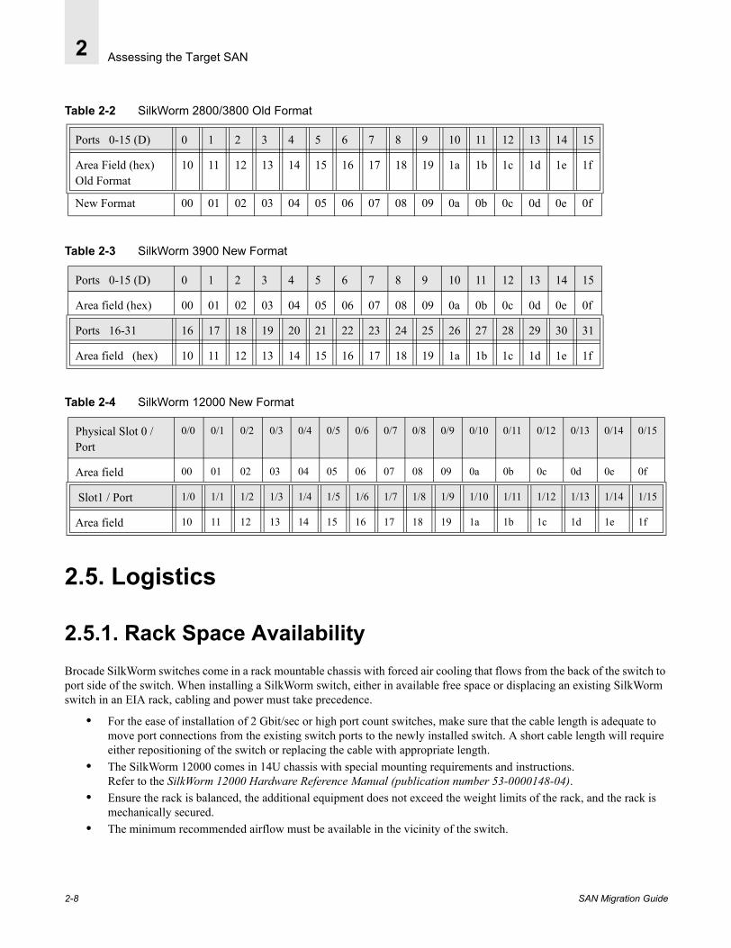
Table 2-2 represents the change between both Core PID format in the second byte (Area field) of the 24-bit PID address. The Area field byte changes from 10-1F to 00-0F after updating the Core PID format. The area field byte 10-1F now represents the upper ports 16-31 of the 32-port switch. Thus moving a port connection from a 16-port switch to a 32-port or higher port count switch with an offset of 16 will eliminate the need to reboot the host.
Note: Moving a port connection from a 16-port switch to a 32-port, or higher port count switch, with an offset of 16 will eliminate the need to reboot the host.
Table 2-1 Comparing Old and New Core PID Format
24-bit address = Domain(8 bits)
Area(8 bits)
AL_PA(8 bits)
SAN Migration Guide 2-7
Assessing the Target SAN2
Table 2-2 SilkWorm 2800/3800 Old Format
Table 2-3 SilkWorm 3900 New Format
Table 2-4 SilkWorm 12000 New Format
2.5. Logistics
2.5.1. Rack Space Availability Brocade SilkWorm switches come in a rack mountable chassis with forced air cooling that flows from the back of the switch to port side of the switch. When installing a SilkWorm switch, either in available free space or displacing an existing SilkWorm switch in an EIA rack, cabling and power must take precedence.
• For the ease of installation of 2 Gbit/sec or high port count switches, make sure that the cable length is adequate to move port connections from the existing switch ports to the newly installed switch. A short cable length will require either repositioning of the switch or replacing the cable with appropriate length.
• The SilkWorm 12000 comes in 14U chassis with special mounting requirements and instructions. Refer to the SilkWorm 12000 Hardware Reference Manual (publication number 53-0000148-04).
• Ensure the rack is balanced, the additional equipment does not exceed the weight limits of the rack, and the rack is mechanically secured.
• The minimum recommended airflow must be available in the vicinity of the switch.
Ports 0-15 (D) 0 1 2 3 4 5 6 7 8 9 10 11 12 13 14 15
Area Field (hex)Old Format
10 11 12 13 14 15 16 17 18 19 1a 1b 1c 1d 1e 1f
New Format 00 01 02 03 04 05 06 07 08 09 0a 0b 0c 0d 0e 0f
Ports 0-15 (D) 0 1 2 3 4 5 6 7 8 9 10 11 12 13 14 15
Area field (hex) 00 01 02 03 04 05 06 07 08 09 0a 0b 0c 0d 0e 0f
Ports 16-31 16 17 18 19 20 21 22 23 24 25 26 27 28 29 30 31
Area field (hex) 10 11 12 13 14 15 16 17 18 19 1a 1b 1c 1d 1e 1f
Physical Slot 0 / Port
0/0 0/1 0/2 0/3 0/4 0/5 0/6 0/7 0/8 0/9 0/10 0/11 0/12 0/13 0/14 0/15
Area field 00 01 02 03 04 05 06 07 08 09 0a 0b 0c 0d 0e 0f
Slot1 / Port 1/0 1/1 1/2 1/3 1/4 1/5 1/6 1/7 1/8 1/9 1/10 1/11 1/12 1/13 1/14 1/15
Area field 10 11 12 13 14 15 16 17 18 19 1a 1b 1c 1d 1e 1f
2-8 SAN Migration Guide
Assessing the Target SAN 2
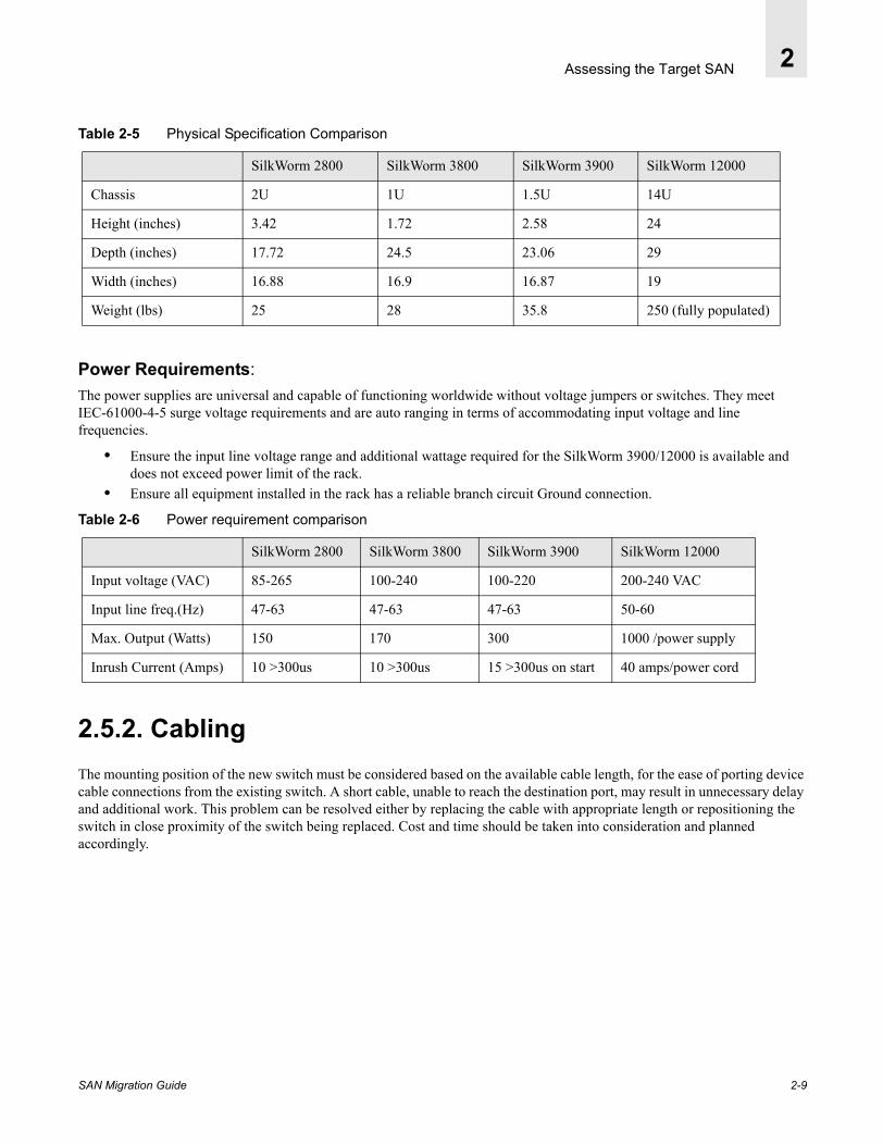
Table 2-5 Physical Specification Comparison
Power Requirements:The power supplies are universal and capable of functioning worldwide without voltage jumpers or switches. They meet IEC-61000-4-5 surge voltage requirements and are auto ranging in terms of accommodating input voltage and line frequencies.
• Ensure the input line voltage range and additional wattage required for the SilkWorm 3900/12000 is available and does not exceed power limit of the rack.
• Ensure all equipment installed in the rack has a reliable branch circuit Ground connection.
Table 2-6 Power requirement comparison
2.5.2. Cabling The mounting position of the new switch must be considered based on the available cable length, for the ease of porting device cable connections from the existing switch. A short cable, unable to reach the destination port, may result in unnecessary delay and additional work. This problem can be resolved either by replacing the cable with appropriate length or repositioning the switch in close proximity of the switch being replaced. Cost and time should be taken into consideration and planned accordingly.
SilkWorm 2800 SilkWorm 3800 SilkWorm 3900 SilkWorm 12000
Chassis 2U 1U 1.5U 14U
Height (inches) 3.42 1.72 2.58 24
Depth (inches) 17.72 24.5 23.06 29
Width (inches) 16.88 16.9 16.87 19
Weight (lbs) 25 28 35.8 250 (fully populated)
SilkWorm 2800 SilkWorm 3800 SilkWorm 3900 SilkWorm 12000
Input voltage (VAC) 85-265 100-240 100-220 200-240 VAC
Input line freq.(Hz) 47-63 47-63 47-63 50-60
Max. Output (Watts) 150 170 300 1000 /power supply
Inrush Current (Amps) 10 >300us 10 >300us 15 >300us on start 40 amps/power cord
SAN Migration Guide 2-9

Assessing the Target SAN2
2.5.3. Small Form Factor Pluggable The GBIC modules used on the Brocade SilkWorm 2000 series switch use SC type Fibre Channel cable connections while all 2 Gbit/sec switch ports requires SFP (Small Form Factor Pluggable) mating LC cable connector types. Therefore, plan ahead for a cable conversion from SC to LC prior to moving device connections to a 2 Gbit/sec switch port.
• Interswitch links (ISL) between SilkWorm 3800/3900/12000 switches require LC-LC cable connections. • Interswitch links (ISL) between a SilkWorm 2000 Series switch and a SilkWorm 3800/3900/12000 switch requires
SC-LC cable. You may require a SC-LC interim cable connection during an incremental upgrade.• All existing devices migrating from a SilkWorm 2000 Series switch to 2 Gbit/sec switch require an SC port
connection converted to LC to mate with the SilkWorm 3800/3900/12000 SFP. • When utilizing the existing patch panel and cabling infrastructure supported by either cables with a core diameter of
62.5 or 50 microns, make sure that the distance requirement for 2 Gbit/sec transmission is observed.
2.6. Replacing an Existing SwitchTo facilitate fabric management, operation, and to simplify the migration process, it is recommended that a new switch be configured with the exact same parameters of the switch being replaced. This can be accomplished by compiling switch configuration data in advance for all switches in the fabric prior to migration. The configuration data consisting of Switch login; Name, Domain ID, IP address, and License, etc., will assist in the process of preparing the new switch. The key information, listed below, can be obtained by logging into each switch through a telnet session and executing the configShow command.
• Switch Name: Security126• Domain ID: 5• IP Address: 192.168.156.126• License:
The configShow command provides a complete list of the switch parameters. Most of the parameter settings are left to factory default. Some of these parameters, such as SNMP and Fabric Watch, may have been set by the user. The new switch must also reflect user settings obtained from the output of the Configshow command from the 1 Gbit/sec switch being replaced. Do a configupload to preserve the information of the existing switch being replaced.
Table 2-7
Core Diameter 2 Gbit 1 Gbit
62.5microns 2-90m 2-300m
50 microns 2-300m 2-500m
2-10 SAN Migration Guide

SAN Migration Guide
Chapter
3
Developing a Migration StrategyThe migration process can be simplified by laying out the migration plan in advance. Besides cabling, rack space, and power requirements, other factors discussed in Logistics on page 2-8 may significantly impact the SAN operations. The current configuration and operational requirement of a target SAN may impose additional constraints. The key to a successful migration is to minimize fabric interruption or to completely eliminate downtime whenever possible, by identifying issues in advance.
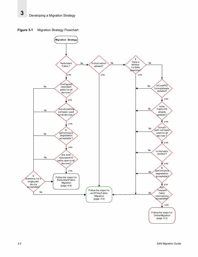
The preliminary groundwork in the evaluation phase lays out the foundation for the migration process. The flowchart in Figure 3-1 on page 3-2 will assist you in determining the best migration strategy for you. After carefully answering the questions that apply to your unique situation, the process will fall into one of the following categories:
• Single Fabric Online Migration• Redundant Fabric Online Migration• Offline Fabric Migration
3-1
Developing a Migration Strategy3
Figure 3-1 Migration Strategy Flowchart
Follow the steps f orOnline Migration
(page 4-2)
Is multi-path sof tware
used f or alldev ices ?
Is the f abricresilient ?
Isperf ormancedegradation acceptable?
Are f requent
f abricinterruptionsacceptable?
Is Core PIDf ormat already
updated?
Is theFabric OS
alreadyupdated ?
Migration Strategy
No
No
No
No
No
No
y es
No
y es
y es
y es
Isthere awindowf or SAN
downtime?
No No
y es
Is Host rebootallowed?
RedundantFabric ?
Conf iguredredundant
paths f or alldev ices?
Isperf ormancedegradation
acceptable ?
Is multi-pathingsof tware usedf or all dev ices ?
Are bothredundant I/O
paths open to alldev ices?
y es
y es
y es
No
No
No
No
Follow the steps f orRedundant Fabric
Migration(page 4-9)
y es
y es
y es
y es
y es
Follow the steps f oran Of f line Fabric
Migration(page 4-5)
Isdowntime f or a
single pathdev ice
acceptable?
No
3-2 SAN Migration Guide

Developing a Migration Strategy 3
3.1. Single Fabric Online Migration QualificationA single resilient fabric providing multiple paths to each device via different switches may be qualify for an online migration by replacing one switch at a time and leaving an alternate path open for I/O. In this case, the new switch must be able to join the existing fabric immediately upon introduction. An online migration is possible, only if the answer to all the following questions is “yes”.
Table 3-1 Single Fabric Online Migration Assessment
3.2. Redundant Fabric Online Migration QualificationA redundant fabric provides flexibility to upgrade a fabric by bringing it offline while redirecting active I/Os to the other fabric. Current I/O operations are not impacted as a result of migration activity. Please note that the hosts are operating in degraded mode with no data path protection. Any failure on an active path will completely cease I/Os.With proper planning downtime can be minimized. Once the fabric upgrade is complete and verified, it can be brought online by restoring the I/O paths. The migration process can be repeated for the second fabric after all I/O paths are successfully restored on the first fabric. An online migration is possible, only if the answer to all the following questions is “yes”.
Note: It is possible that some devices may be singly attached into a redundant fabric. If it is permissible for these devices to go offline, it is not necessary to have multipathing software and redundant paths for all devices.
Core PID format update is not required? yes
Fabric OS update is not required? yes
Multi-pathing Software is installed and active on each fabric device and downtime for single attach devices is acceptable?
yes
The fabric is resilient yes
Performance degradation is acceptable during the upgrade? yes
Frequent I/O interruptions from fabric rebuild are acceptable? yes
Host rebooting is not required for PID bindings consolidation? yes
SAN Migration Guide 3-3

Developing a Migration Strategy3
Table 3-2 Redundant Fabric Online Migration Assessment
Guideline: Rebooting a host will completely cease I/Os on all active paths. If the Host Bus Adapter (HBA) configuration file storage persistent binding is done via PID, consider an alternate method of avoiding host reboot as described in Chapter 5, Prepare to Migrate.
3.3. Offline Fabric Migration QualificationIn situations where a fabric can be brought offline to perform the migration the I/Os are completely ceased for the duration of downtime. This is the safest and most convenient method to migrate to a 2 Gbit/sec fabric. All the issues discussed in Chapter 2, Assessing the Target SAN can be addressed easily in the absence of active I/Os. This method must be considered whenever possible. Making necessary preparations in advance helps minimize the fabric downtime.
Redundant fabric topology? yes
Configured redundant paths for each device via the fabric or if the device is single pathed, downtime for that device is acceptable?
yes
Multi-pathing Software installed and active on each fabric’s devices that require it? yes
Both redundant paths are open to devices that require multipathing? yes
Performance degradation is acceptable during the upgrade. This performance degradation results from one path to the fabric being temporarily unavailable and where the host and storage implement active/active pathing.
yes
No protection mode is acceptable for migration duration? yes
Host re-booting is not required for PID bindings consolidation? yes
3-4 SAN Migration Guide

Developing a Migration Strategy 3
3.4. Readiness ChecklistBy now you should have an understanding of the existing SAN configuration and the additional steps required on your part to prepare the new 2 Gbit/sec switches for the migration. The following check list will assist you with planning, managing, and tracking the migration activity.
Table 3-3 Phase-1 Assessment
SAN TopologySingle Fabric
Redundant Fabric
Planning Fabric Topology change
Hosts configurationSingle or multi-path to storage
Multi-pathing software installed
2 Gbit/sec HBA hardware and device drivers upgrade plan
Storage port Persistent binding by PID
System re-boot is permissible
LogisticsRack space availability (switch mounting proximity)
Power
Cable length and type
Existing Switch ConfigurationFirmware upgrade required
Core PID format update planned
Switch configuration and switch port connectivity information obtained. (ex. switch Name, IP address, Licensing, and switch port-device connectivity information)
Assessment Completed
SAN Migration Guide 3-5

Developing a Migration Strategy3
Table 3-4 Phase-2 Planning and Scheduling
Figure 3-2 Phase-3 Preparation
Table 3-5 Phase-4 Executing Migration Steps
Online Single fabric Migration or
Online Redundant Fabric Migration or
Offline Fabric Migration
Scheduling Migration time
Plan accepted
New switch configuration setup (offline)
Switch Positioning and Mounting
Power requirement
Correct cable length and type availability
Zoning strategy in place
Preparation completed
2 Gbit/sec switch configuration parameters Setup
Existing switch Core PID Upgrade
PID persistent binding consideration
Zoning update
3-6 SAN Migration Guide

SAN Migration Guide
Chapter
4
Migration ProcedureThe following sections define the migration processes:
• Single Fabric Online Migration on page 4-2• Offline Fabric Migration on page 4-5• Redundant Fabric Online Migration on page 4-9
Based on your preliminary assessment of the existing Fabric, choose the appropriate migration strategy and follow the process flow. Verify that the target fabric configuration meets the migration qualification as described in Chapter 2, Assessing the Target SAN.
4-1

Migration Procedure4
4.1. Single Fabric Online MigrationFigure 4-1 Single Fabric Online Migration Flowchart
WARNING : This strategy assumes anincremental sw itch replacement. Make sureall devices have an alternate open pathbefore disabling the existing sw itch.Disabling or enabling a sw itch w ill alsocause fabric segmentation and a fabricrebuild. I/O may pause for the duration ofthese events.
Does thisswitch have anactive I/O path
open?
All existing fabricswitches have
been replaced?
one
Move all deviceconnections to the
new switch
Select a Switch thatneeds to be replaced.
Failover to alternateopen path on other
switch(s).
Validate the newfabric
Single Fabric OnlineMigration
y es
No
Failback and restorethe path on the newswitch if necessary
No
y es
Prepare thenew switch
parameters, setDomain ID(page 5-5)
4-2 SAN Migration Guide

Migration Procedure 4
4.1.1. Single Fabric Online Migration Procedure
Note: This procedure is for a single fabric that has been previously assessed for an online migration.
1. Select a switch in the fabric that needs to be replaced.
2. Make sure all active devices on the selected switch have an alternate open path available via another switch in the fabric.3. Redirect active I/Os to an available alternate path on another switch. All I/O paths on this switch must be closed.
For example, if you are running EMC PowerPath software providing multiple access paths to the storage device, a failover is performed to redirect the I/Os to an alternate open path from the Powerpath Console.
4. After verifying all switch ports are inactive, disable the selected switch. Disabling or removing a switch will initiate a fabric re-build process that may momentarily pause I/Os until the fabric becomes stable.
5. Replace the switch with a new pre-configured switch.
Guideline: To minimize downtime during the migration process prepare the new switch in advance. Refer to2 Gbit/sec Switch Preparation on page 5-5.
6. Restore the power to the new switch. 7. Ensure the switch is accessible via Ethernet by pinging the switch using the ping command.8. Establish a telnet session and verify Switch Name, Domain ID, and IP address are identical to the switch being replaced.9. The new switch must have either the identical copy of the current zone configurations or no zone configurations, prior to
joining the existing fabric. When a switch has no effective zone configuration, i.e. all zone configurations are cleared, the zone configuration is propagated from the fabric to the newly joined switch. Thus, a zone configuration can either be manually imported to the new switch or propagated during the fabric rebuild.
Guideline: The recommended method in this case is to clear all zone configurations on the switch that is being added, prior to joining the existing fabric.
10. The new switch is now ready to join the existing fabric. Disable the switch with the command switchDisable. Add one or more Interswitch Links (ISL) as per the fabric configuration.
Note: In a mixed environment that contains SilkWorm 2000 Series switches, an Interswitch Link (ISL) Fibre Channel cable with an SC connector on one end and an LC connector on other end may be required.
11. Move each device connection from the disabled switch port to its respective port on the new switch, to keep the PID consistent when hard zoning (port, domain) is utilized. Worldwide Name (WWN) based zoning is more flexible and does not impose the same restriction.
12. Enable the new switch by issuing the command switchEnable.13. Verify that the new switch has joined the fabric successfully by examining the entry of the new switch in the
FabricShow command output.14. Verify the zone configuration on the new switch is propagated during the fabric build process, by examining the output of
the cfgShow command and compare to the zoning configuration in the existing fabric.
SAN Migration Guide 4-3
Migration Procedure4
15. Make sure all devices successfully logon to the new switch fabric ports by executing the nsShow and switchShow commands.
16. Verify host access to the storage device via newly established switch fabric ports by examining the host Operating System (OS) mapping of the target. In some cases, this step may require device re-scanning.
17. If necessary, restore the previously closed path from multi-pathing software console.18. Repeat step 1-15 until all switches targeted for replacement have been successfully replaced.19. Validate the entire new switch fabric by executing the fabricShow, nsAllshow, and/or nsShow commands.
• fabricshow command output displays fabric membership information• nsallshow command output displays global name server information• nsshow command output displays local name server information
20. Restore I/O operations.
4-4 SAN Migration Guide

Migration Procedure 4
4.2. Offline Fabric MigrationFigure 4-2 Offline Fabric Migration Flowchart
Schedule a time tobring the fabric offline.
PlanningIncrementalMigration?
Offline FabricMigration
See Guideline 2
Follow the CorePID UpdateProcedure(page 5-1)
Is Core PID Format
alreadyset ?
Prepare 2 Gbit/secswitch parameters ,
set Domain ID(page 5-5)
Is HostHBA Persistentbindings method
by PID ?
yes
yes
yes
No
No
No
Import/UpdateZoning
See Guideline 3
Follow the PIDPersistent binding
procedure(page 5-3)
Move the host andstorage cable
connections to thecorresponding
2 Gbit/sec switch ports
Validate the fabric.
See Guideline 1
Guidelines1) The fabric remains segmented unless the Core PIDFormat is changed on all switches in the existing fabric
2) The fabric stays down until all switches are migrated.No Core PID Format change is required.
3) Import the zoning configuration to at least one switchwhen the fabric is replaced with new switches. Thezone configuratiuon is propagated to all adjecentswitches during an incremental upgrade.
SAN Migration Guide 4-5
Migration Procedure4
When all switches in the fabric are being replaced at once, there is no need to upgrade the Fabric OS and Core PID since the existing switches will be removed from the fabric. However, in a large complex fabric environment, an incremental migration process may be more manageable and less prone to errors. Based on your assessment of the fabric, proceed with the migration using one of the following procedures:
• Incremental Fabric Upgrade Procedure on page 4-6• Fabric Replacement Procedure on page 4-7
Before proceeding, ensure there are no active I/Os running on the fabric. The device may also be prevented from logging into the switch by disabling the switch.
Guideline: This procedure requires the fabric to be offline for the duration of the migration process, therefore, a downtime must be scheduled in advance.
4.2.1. Incremental Fabric Upgrade Procedure1. The incremental migration process requires that all existing fabric switches must be upgraded to a compatible Core PID
format. Determine if the existing switch fabric requires Fabric OS and Core PID format upgrade.
2. If the Core PID Format upgrade is required, follow the procedure described in Core PID Upgrade Procedure on page 5-1. 3. The new switch can be configured in advance with the identical parameters of the switch being replaced for the purpose of
minimizing the SAN downtime. Please refer to 2 Gbit/sec Switch Preparation on page 5-5.4. Replace the selected switch with a pre-configured switch.5. Once the new switch is positioned and secured in place, restore the power.6. Ensure that the switch is accessible via Ethernet by pinging the switch, using the ping command.7. Establish a telnet session and verify the switch parameters (including: Switch Name, Domain ID, IP address, Licenses,
and user configurable parameters) are identical to the switch being replaced.8. The new switch must have either the identical copy of the current fabric zone configurations or no zone configurations,
prior to joining the existing fabric. When a switch has no effective zone configuration, i.e. all zone configurations are cleared, the zone configuration is propagated from the fabric to the newly joined switch. Thus a zone configuration can be either manually imported to new switch or propagated during the fabric rebuild.
Note: Clearing all zone configurations on the new switch prior to joining the existing fabric is the recommended method in this case.
9. The new switch is now ready to join the existing fabric. Add one or more Interswitch Links (ISLs) as per the Fabric configuration.
Guideline: In a mixed environment that contains SilkWorm 2000 Series switches, an Interswitch Link (ISL) Fibre Channel cable with an SC connector on one end and an LC connector on other end, may be required.
10. Verify that the new switch has joined the fabric successfully by examining the entry of the new switch in the FabricShow command output.
11. Verify the zone configuration on the new switch is propagated correctly during the fabric build process, by examining the output of the cfgShow command and compare to the zoning configuration in the existing fabric.
4-6 SAN Migration Guide

Migration Procedure 4
12. If host binding is effective, make sure the persistent binding on host is done via WWN. If the method of Storage port persistent binding is PID, please follow the procedure described in Port ID Persistent Binding Procedure on page 5-3.
13. Move each device connection from the disabled switch port to its respective port on the new switch, to keep the PID consistent when port based zoning is effective.
Note: Worldwide Name (WWN) based zoning is more flexible and does not impose the same restriction.
Guideline: Connectors may need to be converted from SC to LC before connecting to the new switch. When positioning and securing the new switch, make sure cable length is adequate.
14. Make sure all devices are successfully logged on to the new switch fabric ports by executing the nsShow and switchShow commands.
15. Verify host access to the storage devices via the newly established switch fabric ports by examining the Operating System (OS) mapping of the target. In some cases this may require device re-scanning.
16. Repeat steps 1-15 for until all switches targeted for replacement have been successfully replaced.17. Validate the entire new switch fabric by executing the fabricShow, nsAllshow, and/or nsShow commands.
• fabricshow command output displays fabric membership information• nsallshow command output displays global name server information• nsshow command output displays local name server information
18. Restore I/O operations.
4.2.2. Fabric Replacement Procedure
Note: Replacing all switches in the fabric imposes the additional step of managing and tracking the device connectivity during the migration process. Before the switches are disabled and devices have been disconnected, a connectivity profile must be created. It is extremely important that consistency be maintained, especially, in the case of port ID based zoning implementation. Device cables must be labeled properly identifying Switch Domain ID and port number and a label for the identifying the connecting device.
1. Save the existing fabric zoning configuration in a text file format, on a server, by administering the configupload command from a telnet session. Refer to Propagating an Existing Zone Configuration on page 5-7.
2. The new switch can be configured in advance with identical parameters of the existing switch, for the purpose of minimizing SAN downtime. Please refer to 2 Gbit/sec Switch Preparation on page 5-5.
3. Disable all existing switches in the fabric and replace each switch with an identically configured new switch.
Guideline: When positioning and securing the new switches, make sure the cable length is adequate.
4. Restore power to all switches.5. Ensure each new switch is accessible via Ethernet by pinging the switch, using the Ping command.
SAN Migration Guide 4-7

Migration Procedure4
6. Establish a telnet session and verify the Switch Name, Domain ID, and IP address are identical to the switch being replaced. Each switch must have a unique Domain ID.
7. Make sure all zone configurations, if any, have been cleared from the new switches. Refer to the Brocade Zoning v3.1/4.1 User’s Guide for more information.
8. Import the zone configuration that was saved in Step 1 to a new switch by downloading the saved text file. Refer to the Propagating an Existing Zone Configuration on page 5-7 for more information.
9. Examine the currently effective zone configuration by executing the cfgshow command.10. The Fabric is ready to be formed. When all switches are on-line, add one or more Interswitch Links (ISLs) as per the
Fabric configuration. You may plan your ISL connections to benefit from the high performance Trunking feature available on switches running Fabric OS 3.x or 4.x.
11. Verify that the new fabric is formed and in stable condition by examining the entry of the new switches in the FabricShow command output display.
12. Before moving device connections make sure the persistent binding on the host is done via WWN. Move each device connection from the disabled switch port to its respective port on the new switch
13. If the PID persistent binding is used, follow the procedure described in Port ID Persistent Binding Procedure on page 5-3.
Note: Worldwide Name (WWN) based zoning is more flexible and does not impose the same restriction.
Guideline: Connectors may need to be converted from SC to LC before connecting to the new switch. When positioning and securing the new switch, make sure cable length is adequate.
14. Make sure all devices are successfully logged on to the new switch fabric ports by executing nsShow, switchShow, and nsAllShow command.
15. Verify host access to the storage devices via the newly established switch fabric ports by examining the host Operating System (OS) mapping of the target. In some cases, this step may require device re-scanning.
16. Validate the entire new switch fabric by executing the fabricShow, nsAllshow, and/or nsShow commands.• fabricshow command output displays fabric membership information• nsallshow command output displays global name server information• nsshow command output displays local name server information
17. Restore I/O operations.
4-8 SAN Migration Guide

Migration Procedure 4
4.3. Redundant Fabric Online MigrationFigure 4-3 Redundant Fabric Online Migration Flowchart
Redundant FabricOnline Migration
Are bothredundant I/O
paths open to alldev ices?
y es
y es
No
Ensure f rommulti-pathing sof tware,
that all paths are open toall dev ices that must
remain online during themigration
No
Select a f abric f ormigration. Redirect allactiv e I/Os f rom this
f abric to an alternateopen f abric
Restore the I/O pathson the upgraded2 Gbit/sec f abric
Follow the steps f or Of f line Fabric Migration
(page 4-5)
Are all f abricsmigrated to2 Gbit/sec ?
Verif y all f abrics
Prepare dev ices with asingle path f or
downtime
SAN Migration Guide 4-9
Migration Procedure4
4.3.1. Redundant Fabric Online Migration Procedure1. Verify that each fabric is configured to provide an alternate path to all fabric attached devices.
2. Verify both paths are open to each device that must remain online during the migration.3. Select one of the two fabrics for migration.4. Close all active paths on the selected fabric and prepare single attach devices for downtime.
For example if you are running a multi-pathing software package EMC Powerpath or equivalent, redirect I/Os by performing a failover to an alternate fabric path.
5. Verify that the selected fabric is free from I/O activity.6. Disable the switches in the selected fabric.7. Follow Offline Fabric Migration on page 4-5.8. Restore I/O operations on the new fabric from the multi-pathing software console.9. Repeat Step 1-8 for the second 1 Gbit/sec fabric.10. Verify both paths are open and restored for each device.
4-10 SAN Migration Guide
SAN Migration Guide
Chapter
5
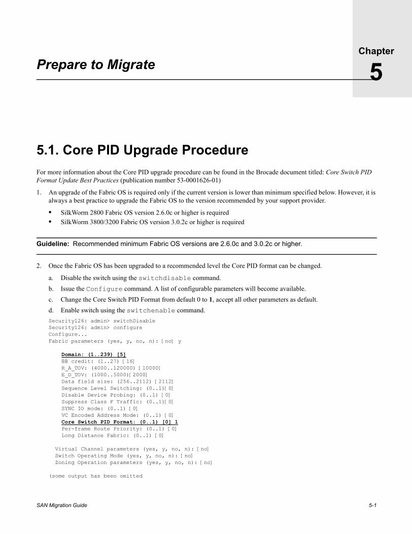
Prepare to Migrate5.1. Core PID Upgrade ProcedureFor more information about the Core PID upgrade procedure can be found in the Brocade document titled: Core Switch PID Format Update Best Practices (publication number 53-0001626-01)
1. An upgrade of the Fabric OS is required only if the current version is lower than minimum specified below. However, it is always a best practice to upgrade the Fabric OS to the version recommended by your support provider.
• SilkWorm 2800 Fabric OS version 2.6.0c or higher is required• SilkWorm 3800/3200 Fabric OS version 3.0.2c or higher is required
Guideline: Recommended minimum Fabric OS versions are 2.6.0c and 3.0.2c or higher.
2. Once the Fabric OS has been upgraded to a recommended level the Core PID format can be changed.
a. Disable the switch using the switchdisable command.b. Issue the Configure command. A list of configurable parameters will become available. c. Change the Core Switch PID Format from default 0 to 1, accept all other parameters as default.d. Enable switch using the switchenable command.Security126: admin> switchDisableSecurity126: admin> configureConfigure...Fabric parameters (yes, y, no, n): [no] y
Domain: (1..239) [5] BB credit: (1..27) [16] R_A_TOV: (4000..120000) [10000] E_D_TOV: (1000..5000)[2000] Data field size: (256..2112) [2112] Sequence Level Switching: (0..1)[0] Disable Device Probing: (0..1) [0] Suppress Class F Traffic: (0..1)[0] SYNC IO mode: (0..1) [0] VC Encoded Address Mode: (0..1) [0] Core Switch PID Format: (0..1) [0] 1 Per-frame Route Priority: (0..1) [0] Long Distance Fabric: (0..1) [0]
Virtual Channel parameters (yes, y, no, n): [no] Switch Operating Mode (yes, y, no, n): [no] Zoning Operation parameters (yes, y, no, n): [no]
(some output has been omitted
5-1

Prepare to Migrate5
Figure 5-1 Core PID Update Flowchart
Disable switch andupgrade to the latest
Fabric OSon all existing f abric
switches
Disable the switch andset the
Core PID f ormat to 1on all switches
* Switch FOS< 2.4.1a or
3.0.1c ?
Enable switches andv erif y the f abric
( No segmentation)
y es
No
Optional step( Strongly recommend
to upgrade to latestacceptable FOS lev el)
Return
* Recommended Fabric OSversions 2.6.0c and 3.0.2c or later
5-2 SAN Migration Guide

Prepare to Migrate 5
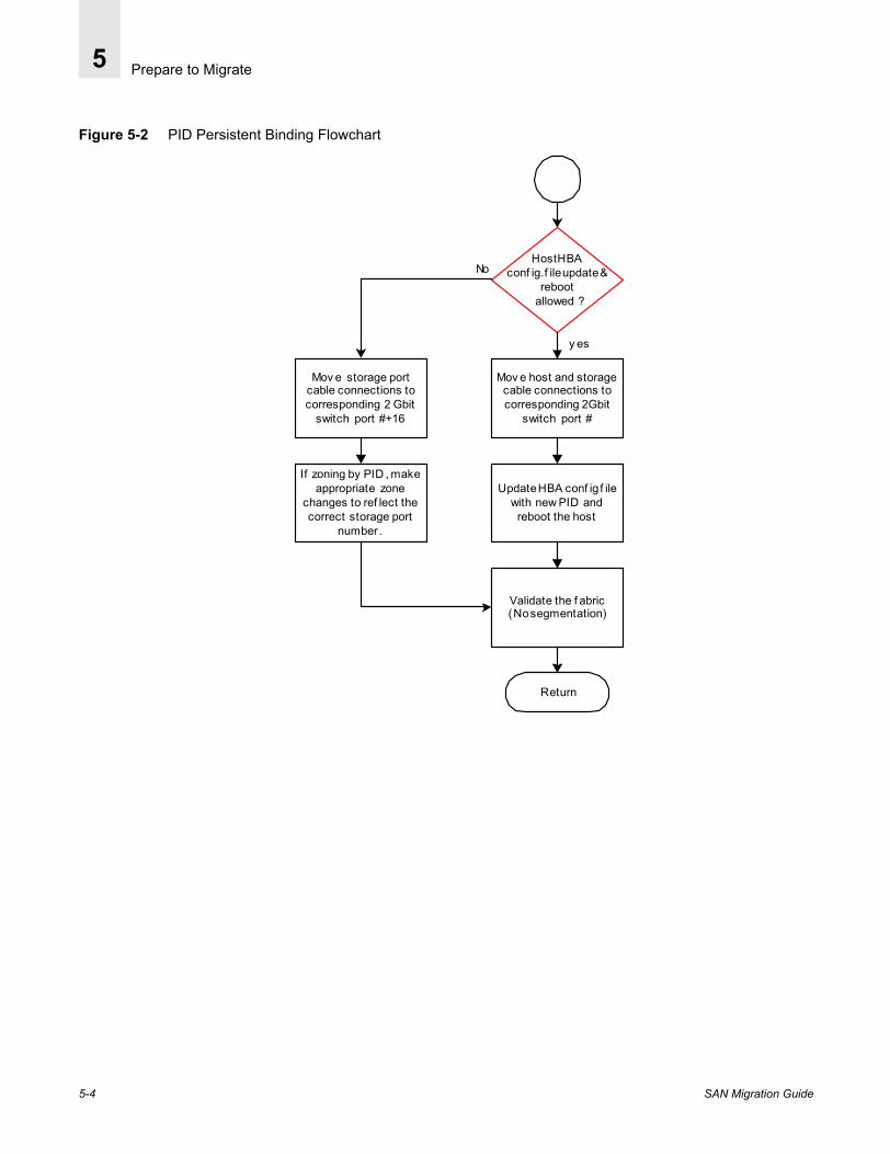
5.2. Port ID Persistent Binding Procedure1. Verify the storage port persistent binding method by examining the HBA configuration file of the attached host. Proceed
with this procedure only if the Port ID (PID) persistent binding method is applied and a Core PID format update is performed.
2. Determine if a host re-boot is allowed. If re-booting the host is an acceptable option then follow steps 3-6, otherwise go to step 7.
3. Move both storage and host port cable connections from the 1 Gbit/sec switch ports to the corresponding switch ports on the new switch.
4. Update the binding entry in the HBA configuration file, reflecting the correct Port ID (PID).
5. Reboot the host. The updated PID entry of the configuration file becomes effective only after the is host rebooted.
6. Verify that the pre-assigned targets on the storage port are accessible after a preliminary scanning is performed by the host operating system.
7. In situations where it is not permissible to reboot the host, consider changing the physical port number on the new switch to match the HBA configuration file PID binding entry.
8. Plan to move the storage port connection from the port number on the current switch to the new switch port with a port count offset of +16. Refer to Table 2-1 on page 2-7
9. If the Port_ID (PID) base hard zoning is implemented, modify the zone configuration entry for the storage port, reflecting the correct port number of 2 Gbit/sec switch.
10. Move the storage port connection, as planned in step 8.
11. Move the host connection without applying an offset.
12. Verify that the host continues accessing the pre-assigned targets on the storage port.
SAN Migration Guide 5-3
Prepare to Migrate5
Figure 5-2 PID Persistent Binding Flowchart
Mov e host and storagecable connections tocorresponding 2Gbit
switch port #
Host HBAconf ig.f ile update &
reboot allowed ?
Mov e storage portcable connections tocorresponding 2 Gbit
switch port #+16
Update HBA conf ig f ilewith new PID and
reboot the host
Validate the f abric( No segmentation)
y es
No
If zoning by PID , makeappropriate zone
changes to ref lect thecorrect storage port
number .
Return
5-4 SAN Migration Guide

Prepare to Migrate 5
5.3. 2 Gbit/sec Switch Preparation Figure 5-3 2 Gbit/sec Switch Preparation
Set the matchingDomain ID , switch
name, IP address andconf iguration f ile
settings
Replacing anexisting switch ?
When adding a newswitch
set the uniqueDomain ID, switch
name.
Clear the zoneconf iguration on the
2 Gbit switch
Disable the switchbeing replaced and
Migrate to the2 Gbit switch
y es
No
All existingswitches
replaced f orNon-incremental
Migration?
No
y es
Return
SAN Migration Guide 5-5

Prepare to Migrate5
5.3.1. Assigning IP an AddressFor SilkWorm 12000 switch setup information, refer to the Brocade SilkWorm 12000 Hardware Reference Manual (publication number: 53-0000148-04). The following items are required for configuring and connecting a SilkWorm 3800, 3900, or 12000 to a fabric.
The new switch must be set with an Ethernet IP address to allow the connections for switch configuration, monitoring status via telnet session. For detailed instructions, please refer to the specific Brocade SilkWorm hardware manual for your switch.
• Switch installed and connected to a power source• Workstation with a terminal emulator application (such as Hyper terminal)• Serial cable shipped with the switch connected between switch and host serial port • An unused IP address• Ethernet cable for connecting the switch to a network
5.3.2. Switch Configuration Parameters Setup From the fabric management point of view, each switch in the fabric must have a unique Switch Name, Domain ID, and IP address. If a SilkWorm switch is a new addition to the fabric, a unique Switch Name and Domain ID must be set before joining the fabric. However, if it is replacing an existing switch, it should mirror the Domain ID, Switch Name, Password, IP address of the switch being replaced.
The configShow command provides a complete list of existing switch parameter configuration. Most parameter settings are left to factory default. Some of these parameters such as SNMP and Fabric Watch may have been set by the user. The new switch must also reflect user settings obtained from the configShow output of the existing switch during assessment.
After the switch has been configured with an IP address, a telnet session can be initiated from a PC or UNIX system to configure the switch parameters. Log in as the ‘admin’ user and supply the appropriate password.
1. The switch name is set by supplying the name via telnet. For example: SwitchName “newname”
2. The user password is set by typing command “passwd” and requested information.
3. Licenses can be verified, added or removed by entering the commands: LicenseShow, LicenseADD, or LicenseRemove.
4. The version of Brocade Fabric OS on the switch can be verified using the Version command. If necessary upgrade to the recommended version level.
5. Each switch in the fabric must be assigned a unique Domain Identifier (Domain ID), by default, the switch Domain ID is set to 1. Since the switch Domain ID is also considered formulating the 24-bit port address (PID), to be consistent, the new switch must be assigned the identical Domain ID of the previous switch. Setting the Domain ID is a disruptive procedure as a switch configuration change requires switch to be disabled first.
Example:Changing the Domain ID
Security126: admin> switchDisableSecurity126: admin> configureConfigure...Fabric parameters (yes, y, no, n): [no] y
Domain: (1..239) [5] BB credit: (1..27) [16] R_A_TOV: (4000..120000) [10000] E_D_TOV: (1000..5000)[2000] Data field size: (256..2112) [2112]
5-6 SAN Migration Guide
Prepare to Migrate 5
Sequence Level Switching: (0..1)[0] Disable Device Probing: (0..1) [0] Suppress Class F Traffic: (0..1)[0] SYNC IO mode: (0..1) [0] VC Encoded Address Mode: (0..1) [0] Core Switch PID Format: (0..1) [0] 1 Per-frame Route Priority: (0..1) [0] Long Distance Fabric: (0..1) [0]
Virtual Channel parameters (yes, y, no, n): [no] Switch Operating Mode (yes, y, no, n): [no] Zoning Operation parameters (yes, y, no, n): [no]
(some output has been omitted
5.3.3. Propagating an Existing Zone ConfigurationThe zoning configuration on a switch that is joining an existing fabric, or when replacing the entire fabric, can be accomplished via one of the methods listed below. Unless it is a new fabric with no defined zone configuration, the most effective and straight forward method of zone configuration propagation is a fabric rebuild process.
1. Zone Configuration Propagation During Fabric Rebuild
2. Importing a Zone Configuration From an Existing Switch
3. Copying Directly from a 1 Gbit/sec to 2 Gbit/sec Switch
4. Merging Two Zone Configurations
Thus a zone configuration can be either manually imported to new switch, propagated during fabric rebuild, or two zone configurations can be merged. For more information refer to the Brocade Zoning User’s Manual for more information.
5.3.3.1. Zone Configuration Propagation During Fabric RebuildIf a switch is joining an existing fabric, the switch must not have any active zone configuration in effect. It must be cleared before it is capable of merging with the fabric. The active zone configuration of the fabric is propagated to the new switch after successfully joining the fabric.
Example:Clearing the Zone Configuration on 2 Gbit/sec Switch
security43:admin> cfgdisableUpdating flash...security43:admin> cfgclearDo you really want to clear all configurations? (yes, y, no, n): [no] ysecurity43:admin> cfgsaveUpdating flash...security43:admin> cfgshowDefined configuration: no configuration defined
Effective configuration: no configuration in effect
SAN Migration Guide 5-7
Prepare to Migrate5
5.3.3.2. Importing a Zone Configuration From an Existing Switch
Note: This method is appropriate when an entire 1 Gbit/sec fabric is being replaced at the same time.
The active zone configuration of the fabric must be imported to at least one of the switches of the newly constructed 2 Gbit/sec fabric. The active zone configuration is propagated to the remaining fabric switches. This method requires the active zone configuration of the fabric be saved on a server as a text file, edited, and then downloaded on to a 2 Gbit/sec switch.
The following is an example of importing a Zone configuration from a 1 Gbit/sec switch (switch name=int94) to a 2 Gbit/sec switch (switch name=security43).
1. Save the effective configuration to a server.
int194:admin> cfgshowDefined configuration: cfg: Left_cfg173 Left_zone_int173 zone: Left_zone_int173 Solaris_int173_HBA0; Hba0_sym_p5ba alias: Hba0_sym_p5ba 5,20 alias: Solaris_int173_HBA0 3,4
Effective configuration: cfg: Left_cfg173 zone: Left_zone_int173
3,4 5,20
int194:admin> configuploadServer Name or IP Address [host]: 192.168.162.173User Name [user]: rootFile Name [config.txt]: left_cfg173.txtProtocol (RSHD or FTP) [rshd]: ftpPassword:upload complete
2. Edit the saved file. Delete all but zoning related entries as shown.
Example:Edited file
zoning.check.nodeNameDisabled:0zoning.defaultZone:1zoning.inactive.access:1
[Zoning]cfg.Left_cfg173:Left_zone_int173zone.Left_zone_int173:Solaris_int173_HBA0;Hba0_sym_p5ba alias.Hba0_sym_p5ba:5,20alias.Solaris_int173_HBA0:3,4enable:Left_cfg173
[End]
3. Download the edited zone configuration text file to the new switch.
security43:admin> cfgshowDefined configuration: no configuration defined
5-8 SAN Migration Guide

Prepare to Migrate 5
Effective configuration: no configuration in effect
security43:admin> switchdisablesecurity43:admin> configdownloadServer Name or IP Address [host]: 192.168.162.173User Name [user]: rootFile Name [config.txt]: left_cfg173.txtPassworddownload complete
security43:admin> cfgshowDefined configuration: cfg: Left_cfg173 Left_zone_int173 zone: Left_zone_int173 Solaris_int173_HBA0; Hba0_sym_p5ba alias: Hba0_sym_p5ba 5,20 alias: Solaris_int173_HBA0 3,4
Effective configuration: cfg: Left_cfg173 zone: Left_zone_int173 3,4 5,20
5.3.3.3. Copying Directly from a 1 Gbit/sec to 2 Gbit/sec SwitchWhen an entire 1 Gbit/sec switch fabric is being upgraded, a 2 Gbit/sec switch is unable to join the existing fabric because of the Core PID format incompatibility, consider isolating at least one switch in the 1 Gbit/sec fabric and update its Core PID format. After ensuring that the new 2 Gbit/sec switch has no effective configuration, extend an ISL between both switches. The zone configuration will be propagated from 1 Gbit/sec switch to 2 Gbit/sec switch in the process of forming a two switch fabric.
Make this new 2 Gbit/sec switch with an effective zone configuration, the first switch of the 2 Gbit/sec fabric. Any additional 2 Gbit/sec switch joining the fabric will obtain its zoning configuration image from this switch.
5.3.3.4. Merging Two Zone ConfigurationsA third option of merging two fabric is also available via Brocade Fabric merge utility that is capable of merging two zone configurations each from different fabric after verifying that no zone conflict condition exists. This method, even though highly beneficial when merging two large fabrics, is not appropriate in this case. For detailed information please refer to the Brocade Zoning User’s Manual.
SAN Migration Guide 5-9

Prepare to Migrate5
5.4. Verify 2 Gbit/sec Switch ParametersAfter the selected procedures have been completed, use the configShow command to verify the switch parameters.
security43:admin> configshowRSCN.end-device.TransmissionMode:0alpaList:1diag.loopID:125diag.mode.burnin:0diag.mode.esd:0diag.mode.lab:0diag.mode.mfg:0diag.postDisable:0diag.retryDisable:0diag.script.SWITCH.BURNIN:switchburnin.shdiag.script.SWITCH.POST1:switchpost1.shdiag.script.SWITCH.POST2:switchpost2.shdiag.test.crossPort.passes:5000diag.test.passes:0diag.test.portLoopback.passes:1000diag.test.silkScreen.passes:180diag.test.spinSilk.passes:120ether.link.mode:AUTOfabric.domain:5fabric.ops.BBCredit:16fabric.ops.E_D_TOV:2000fabric.ops.R_A_TOV:10000fabric.ops.dataFieldSize:2112fabric.ops.mode.fcpProbeDisable:0fabric.ops.mode.isolate:0fabric.ops.mode.longDistance:0fabric.ops.mode.noClassF:0fabric.ops.mode.tachyonCompat:0fabric.ops.mode.unicastOnly:0fabric.ops.mode.useCsCtl:0fabric.ops.mode.vcEncode:0fabric.ops.vc.class.2:2fabric.ops.vc.class.3:3fabric.ops.vc.config:0xc0fabric.ops.vc.linkCtrl:0fabric.ops.vc.multicast:7fc4.fcIp.address:0.0.0.0fc4.fcIp.mask:0.0.0.0fc4.fcp.productId:FC Switchfc4.fcp.vendorId:BROCADEfcAL.alwaysSendRSCN:0fcAL.fanFrameDisable:1fcAL.openSendCLS:0fcAL.useAltBBCredit:0flannel.ops.frameColMethod:pilingflannel.ops.openBBCredit:4gen.fabos:0gen.zone:0http.javaplugin.homeURL:http://java.sun.com/products/pluginhttp.javaplugin.version:1,2,2lcdContrast:128lcdContrast.orange:208ms.PlatEnable:1ms.TDEnable:0ns.prezonemode:0oemLogo:0
5-10 SAN Migration Guide

Prepare to Migrate 5
portCfg:0, 0x10000000; 1, 0x10000000; 2, 0x10000000; 3, 0x10000000; 4, 0x10000000; 5, 0x10000000; 6, 0x10000000; 7, 0x10000000; 8, 0x10000000; 9, 0x10000000; 10, 0x10000000; 11, 0x10000000; 12, 0x10000000; 13, 0x10000000; 14, 0x10000000; 15, 0x10000000; 16, 0x10000000; 17, 0x10000000; 18, 0x10000000; 19, 0x10000000; 20, 0x10000000; 21, 0x10000000; 22, 0x10000000; 23, 0x10000000; 24, 0x10000000; 25, 0x10000000; 26, 0x10000000; 27, 0x10000000; 28, 0x10000000; 29, 0x10000000; 30, 0x10000000; 31, 0x10000000; 32, 0x10000000; 33, 0x10000000; 34, 0x10000000; 35, 0x10000000; 36, 0x10000000; 37, 0x10000000; 38, 0x10000000; 39, 0x10000000; 40, 0x10000000; 41, 0x10000000; 42, 0x10000000; 43, 0x10000000; 44, 0x10000000; 45, 0x10000000; 46, 0x10000000; 47, 0x10000000; 48, 0x10000000; 49, 0x10000000; 50, 0x10000000; 51, 0x10000000; 52, 0x10000000; 53, 0x10000000; 54, 0x10000000; 55, 0x10000000; 56, 0x10000000; 57, 0x10000000; 58, 0x10000000; 59, 0x10000000; 60, 0x10000000; 61, 0x10000000; 62, 0x10000000; 63, 0x10000000;quickLoop.holdOpenInit:0quickLoop.noAlpaZero:0quickLoop.peerWWN:00:00:00:00:00:00:00:00quickLoop.portBitmap:0x0000000000000000quickLoop.softInit:0rlsDisable:1route.delayReroute:0route.embeddedPortBcast:1route.stickyRoutes:0rpc.rapid:1rpc.rstatd:0rpc.rusersd:0shell.delete:0shell.quiet:0snmp.accessList.0.address:0.0.0.0snmp.accessList.0.rw:1snmp.accessList.1.address:0.0.0.0snmp.accessList.1.rw:1snmp.accessList.2.address:0.0.0.0snmp.accessList.2.rw:1snmp.accessList.3.address:0.0.0.0snmp.accessList.3.rw:1snmp.accessList.4.address:0.0.0.0snmp.accessList.4.rw:1snmp.accessList.5.address:0.0.0.0snmp.accessList.5.rw:1snmp.agtParty.0.address:0.0.0.0snmp.agtParty.0.authPrivSecret:Secret C0desnmp.agtParty.0.index:1snmp.agtParty.0.port:162snmp.agtParty.1.address:0.0.0.0snmp.agtParty.1.authPrivSecret:OrigEquipMfrsnmp.agtParty.1.index:2snmp.agtParty.1.port:162snmp.agtParty.2.address:0.0.0.0snmp.agtParty.2.authPrivSecret:privatesnmp.agtParty.2.index:3snmp.agtParty.2.port:162snmp.agtParty.3.address:0.0.0.0snmp.agtParty.3.authPrivSecret:publicsnmp.agtParty.3.index:4snmp.agtParty.3.port:162snmp.agtParty.4.address:0.0.0.0snmp.agtParty.4.authPrivSecret:commonsnmp.agtParty.4.index:5snmp.agtParty.4.port:162snmp.agtParty.5.address:0.0.0.0snmp.agtParty.5.authPrivSecret:FibreChannelsnmp.agtParty.5.index:6snmp.agtParty.5.port:162
SAN Migration Guide 5-11

Prepare to Migrate5
snmp.authentTraps:0snmp.mibCap:103snmp.swEventTrapLevel:0snmp.sysContact:Field Support.snmp.sysDescription:Fibre Channel Switch.snmp.sysLocation:End User Premisesnmp.sysObjectID:1588.2.1.1.1switch.interopMode:0switch.largeEntry.cap:0switch.status.policy.Fans.down:2switch.status.policy.Fans.marginal:1switch.status.policy.FaultyPorts.down:2switch.status.policy.FaultyPorts.marginal:1switch.status.policy.ISLStatus.down:0switch.status.policy.ISLStatus.marginal:0switch.status.policy.MissingSFPs.down:0switch.status.policy.MissingSFPs.marginal:0switch.status.policy.PortStatus.down:0switch.status.policy.PortStatus.marginal:0switch.status.policy.PowerSupplies.down:2switch.status.policy.PowerSupplies.marginal:1switch.status.policy.Temperatures.down:2switch.status.policy.Temperatures.marginal:1thresh.thad:1xlativeModeDisable:0zoning.check.nodeNameDisabled:0zoning.defaultZone:1zoning.inactive.access:1zoning.standardMode:0zoning.transactionFlag:0:Licenses:S9RecRyd9ShASfdW(END)
5-12 SAN Migration Guide
SAN Migration Guide
Chapter
6
Case StudiesThis Chapter provides comprehensive case studies of migration from Brocade SilkWorm 1 Gbit/sec switches to SilkWorm 2 Gbit/sec switches. The case studies use four different OS platforms. The platforms, and associated configurations, are detailed in Appendix A, Operating System Platforms.
In order for a host to access storage, the host adapter driver for the Fiber Channel controller must be installed and configuration file must be set up specifying storage links. For the purpose of this illustration UNIX and Windows based servers were configured using EMC hardware and the software compatibility matrix for Symmetrix storage as described Appendix A, Operating System Platforms. A compatible version of Powerpath, a multi-pathing software from EMC is installed on each host.
In theory the migration process should be transparent to the Operating System platform as long as the fabric path remains consistent with the persistent binding entry of the host HBA configuration setup file. The storage binding implementation method varies on all UNIX OS platforms. Solaris OS persistent binding can be configured either by WWN or Port ID. HP-UX OS uses Port ID, and Windows persistent binding is always done by WWN. Therefore, for a successful migration it is extremely important to understand the current binding implementation on each configured OS platform. Port ID Persistent Binding Procedure on page 5-3 discusses persistent binding and its impact in depth.
6.1. Test Fabric Configuration OverviewThe following test fabric is constructed representing SilkWorm 2000 series and SilkWorm 3200 and 3800 switches to provide redundant IO storage paths to attached hosts via Fabrics A and B. In order for Solaris, AIX, HPUX, and Windows hosts to use the Symmetrix storage in a multipathing environment, they must be configured as described in the EMC Open Systems Environment Product Guide. Appendix A, Operating System Platforms lists the host setup details.
There are a total of three switches in Fabric B interconnected in a core/edge topology. A SilkWorm 3800 (2 Gbit /sec) is configured to provide host connectivity.
This fabric configuration is selected to illustrate a migration case where a lower port count SilkWorm 3800 is a part of an existing fabric and does not need to be replaced. The remaining two SilkWorm 2000 series switches (“Domain_02” and “Domain_07”) are configured as core and edge switches, and will be directly replaced with a SilkWorm 3900.
Note: These fabrics are for example purposes only and do not truly represent a typical core/edge fabric.
Fabric B is used to illustrate the following cases:
• Case 1: Direct Replacement of a 1 Gbit/sec Edge Switch Connecting Storage• Case 2: Direct Replacement of a 1 Gbit/sec Core Switch with a SilkWorm 3900• Case 3: Adding a New SilkWorm 3900 to Fabric B
6-1
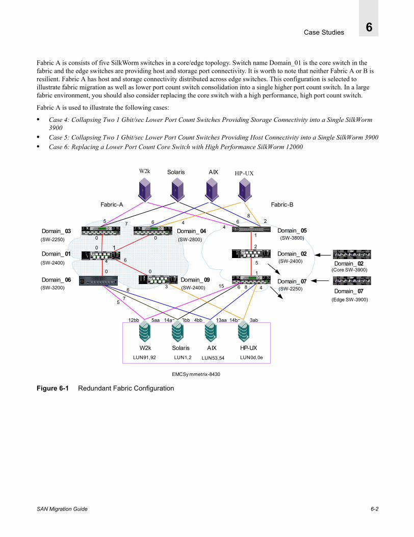
Case Studies 6
Fabric A is consists of five SilkWorm switches in a core/edge topology. Switch name Domain_01 is the core switch in the fabric and the edge switches are providing host and storage port connectivity. It is worth to note that neither Fabric A or B is resilient. Fabric A has host and storage connectivity distributed across edge switches. This configuration is selected to illustrate fabric migration as well as lower port count switch consolidation into a single higher port count switch. In a large fabric environment, you should also consider replacing the core switch with a high performance, high port count switch.
Fabric A is used to illustrate the following cases:
• Case 4: Collapsing Two 1 Gbit/sec Lower Port Count Switches Providing Storage Connectivity into a Single SilkWorm 3900
• Case 5: Collapsing Two 1 Gbit/sec Lower Port Count Switches Providing Host Connectivity into a Single SilkWorm 3900• Case 6: Replacing a Lower Port Count Core Switch with High Performance SilkWorm 12000
Figure 6-1 Redundant Fabric Configuration
SD
Si lkWorm 2 80 0
1 3 5 7 9 1 1 13 1 5
0 2 4 6 8 1 0 12 1 4
W2k HP-UX
SD
Si lkWorm 2 80 0
1 3 5 7 9 1 1 13 1 5
0 2 4 6 8 1 0 12 1 4
5
5
0
0
1
2
6
6
4
0 0 1
7
12bb 5aa 14aa 3bb
7 4
AIX
4
24
14ba 3ab
36 8
68
4bb 13aa
AIXW2k Solaris HP-UX
15
6
0
1
Domain_ 03
SD
Sil kWorm 21000 2 4 6
1 3 5 7
SD
SD
Sil kWorm 21000 2 4 6
1 3 5 7
SD
SD
Sil kWorm 21000 2 4 6
1 3 5 7
SD
5
LUN 91,92 LUN 1,2 LUN 53,54 LUN 0d,0e
EMC Sy mmetrix-8430
Fabric-BFabric-A
SD
Si lkWorm 2 80 0
1 3 5 7 9 1 1 13 1 5
0 2 4 6 8 1 0 12 1 4
Domain_ 01
Domain_ 06
Domain_ 04
Domain_ 09
Domain_ 05
Domain_ 02
Domain_ 07Domain_ 07
Domain_ 02
(SW-2250)
(SW-2250)(SW-2400)
(SW-2400)
(SW-2800)
(SW-2400)
(SW-3800)
(SW-3200)
(Edge SW-3900)
(Core SW-3900)
Solaris
SAN Migration Guide 6-2
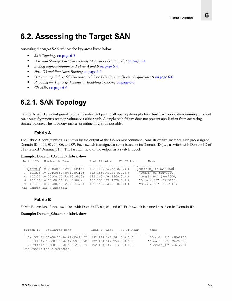
Case Studies 6
6.2. Assessing the Target SANAssessing the target SAN utilizes the key areas listed below:
• SAN Topology on page 6-3• Host and Storage Port Connectivity Map via Fabric A and B on page 6-4• Zoning Implementation on Fabric A and B on page 6-4• Host OS and Persistent Binding on page 6-5• Determining Fabric OS Upgrade and Core PID Format Change Requirements on page 6-6• Planning for Topology Change or Enabling Trunking on page 6-6• Checklist on page 6-6
6.2.1. SAN TopologyFabrics A and B are configured to provide redundant path to all open systems platform hosts. An application running on a host can access Symmetrix storage volume via either path. A single path failure does not prevent application from accessing storage volume. This topology makes an online migration possible.
Fabric AThe Fabric A configuration, as shown by the output of the fabricshow command, consists of five switches with pre-assigned Domain ID of 01, 03, 04, 06, and 09. Each switch is assigned a name based on its Domain ID (i.e., a switch with Domain ID of 01 is named “Domain_01”). The far right field of the output lists switch model.
Example: Domain_03:admin> fabricshow
Fabric BFabric B consists of three switches with Domain ID 02, 05, and 07. Each switch is named based on its Domain ID.
Example: Domain_05:admin> fabricshow
Switch ID Worldwide Name Enet IP Addr FC IP Addr Name------------------------------------------------------------------------ 1: fffc01 10:00:00:60:69:20:3a:66 192.168.162.55 0.0.0.0 "Domain_01"(SW-2400) 3: fffc03 10:00:00:60:69:10:92:b3 192.168.162.59 0.0.0.0 "Domain_03"(SW-2250) 4: fffc04 10:00:00:60:69:10:38:3e 192.168.156.1260.0.0.0 "Domain_04" (SW-2800) 6: fffc06 10:00:00:60:69:c0:06:ec 192.168.172.1270.0.0.0 "Domain_06" (SW-3200) 9: fffc09 10:00:00:60:69:20:1a:b0 192.168.162.58 0.0.0.0 "Domain_09" (SW-2400)The Fabric has 5 switches
Switch ID Worldwide Name Enet IP Addr FC IP Addr Name------------------------------------------------------------------------- 2: fffc02 10:00:00:60:69:20:3e:71 192.168.162.56 0.0.0.0 "Domain_02" (SW-3800) 5: fffc05 10:00:00:60:69:50:05:d3 192.168.162.253 0.0.0.0 "Domain_05" (SW-2400) 7: fffc07 10:00:00:60:69:12:05:fa 192.168.162.113 0.0.0.0 "Domain_07" (SW-2250)The Fabric has 3 switches
SAN Migration Guide 6-3
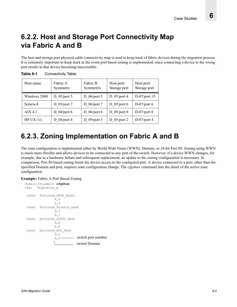
Case Studies 6
6.2.2. Host and Storage Port Connectivity Map via Fabric A and BThe host and storage port physical cable connectivity map is used to keep track of fabric devices during the migration process. It is extremely important to keep track in the event port based zoning is implemented, since connecting a device to the wrong port results in that device becoming inaccessible.
Table 6-1 Connectivity Table
6.2.3. Zoning Implementation on Fabric A and BThe zone configuration is implemented either by World Wide Name (WWN), Domain, or 24-bit Port ID. Zoning using WWN is much more flexible and allows devices to be connected to any port of the switch. However, if a device WWN changes, for example, due to a hardware failure and subsequent replacement, an update to the zoning configuration is necessary. In comparison, Port ID based zoning limits the device access to the configured port. A device connected to a port, other than the specified Domain and port, requires zone configuration change. The cfgshow command lists the detail of the active zone configuration.
Example: Fabric A Port Based Zoning
Host name Fabric A Symmetrx
Fabric B Symmetrix
Host port/ Storage port
Host port/ Storage port
Windows 2000 D_03/port 5 D_06/port 5 D_05/port 4 D-07/port 15
Solaris-8 D_03/port 7 D_06/port 7 D_05/port 6 D-07/port 6
AIX 4.3 D_04/port 6 D_06/port 6 D_05/port 8 D-07/port 8
HP UX-11i D_04/port 4 D_09/port 3 D_05/port 2 D-07/port 4
Domain_03:admin> cfgShowcfg: Migration_A
zone: Portzone_HPUX_hba01 4,4 9,3 zone: Portzone_Solaris_hba0 3,7 6,7 zone: portzone_AIX22_hba0 4,6 6,6 zone: portzone_w2k_hba0 3,5 6,5
switch Domainswitch port number
SAN Migration Guide 6-4

Case Studies 6
Example: Fabric B Port Based Zoning
Domain_05:admin> cfgShow cfg: Migration_B
zone: Portzone_HPUX_hba00 7,4 5,2 zone: Portzone_Solaris_hba1 5,6 7,6 zone: portzone_AIX22_hba1 5,8 7,8 zone: portzone_w2k_hba1 5,4 7,15
6.2.4. Host OS and Persistent BindingIn open system environment, the physical link to a storage port is typically defined either by WWPN or 24-bit Port ID known as persistent binding. Any inconsistency in a configured path and actual fabric path may deny storage access. It is extremely important to verify the current implementation of persistent binding on each host by examining the HBA configuration setup file on the host, refer to Appendix A, Operating System Platforms. Port ID based storage binding requires special recovery steps specific to each Operating system environment.
OS Specifics• Windows 2000 storage binding is done via “World Wide Port Name” instead of 24-bit port ID and therefore requires
no configuration update in this case. It also does not require the recommended port offset of 16 on the SilkWorm 3900. The storage port connection can be moved to any port of the SilkWorm 3900 switch as long as the port based fabric Zoning reflects the correct port. WWPN based zoning does not require any modification.
• Solaris host storage port bindings can be accomplished either by WWPN or PID. If the persistent binding is done via WWPN, there is no need to offset the port count. The storage port connection can be moved to any port of the SilkWorm 3900. If zoning is WWPN based, there is no need to modify zone configuration. Port ID based Zoning must be modified to reflect the correct port.
• AIX and HP-UX both configure hardware path to a storage device using Switch Domain and Port ID. If port count offset is not used, the host configuration update procedure is required. If Zoning is WWPN based, the zone configuration does not need to be updated. Port ID based fabric zoning must be modified to reflect the correct port ID. HP-UX also requires that the path link be removed from a volume prior to any change either in Domain ID or Port number of the switch.
SAN Migration Guide 6-5
Case Studies 6
6.2.5. Determining Fabric OS Upgrade and Core PID Format Change RequirementsThis assessment is required only if an incremental switch migration is planned. If planning to replace all existing 1 Gbit/sec switches, this step can be skipped. In this case, the hosts are provided redundant paths via Fabric A and Fabric B.
1. All switches in Fabric A are being replaced by bringing it offline, therefore this step can be skipped for Fabric A.
2. Fabric B has a SilkWorm 3800 2 Gbit/sec switch that does not need not to be replaced, therefore it requires a compatible Fabric OS and Core PID format verification.
• Verify Fabric OS by logging into the switch and executing the version command. The minimum required level is Fabric OS v3.0.2c. It is always a best practice to upgrade to the most recent Fabric OS.
• Verify the Core PID setup by examining the output of the Configure command. If the Core PID format is not already set to 1, it must be set to one at the appropriate time during the migration process. For more information about setting the core PID format, refer to the Core PID Upgrade Procedure on page 5-1.
6.2.6. Planning for Topology Change or Enabling TrunkingSilkWorm 12000 and 3900 switches forming a core/edge topology supporting 2 Gbit/sec Inter Switch Link (ISL) can benefit from the Advanced Trunking feature. Please refer to Chapter 3, Developing a Migration Strategy.
6.2.7. Checklist1. Topology - Redundant fabric, multipathing software, online migration possible
2. Zoning - Port ID based zoning modification is required
3. Fabric OS upgrade recommended to the most recent release
4. Core PID Format setting required
5. Persistent binding by PID method except Windows host
6. System reboot is not an acceptable option (online Migration)
7. Enabling Trunking, no topology change planned
SAN Migration Guide 6-6

Case Studies 6
6.3. Prepare to Migrate (Example Fabric B)
6.3.1. Bring Fabric B Offline The Operating System platforms described in, Appendix A, Operating System Platforms, (Solaris, AIX, HP-UX and Windows 2000) are configured with EMC Powerpath. SAN Fabric A and B are configured to provide redundant storage access paths to the EMC Symmetrix storage devices to each attached host. Test Case 1 and Test Case 2 are replacing core and edge switches of Fabric B, therefore it must be brought offline. Since paths on Fabric B will be closed for IO transaction, the attached hosts will be operating in degraded mode. This may impact IO performance until Fabric B path is restored. It also means that there is no fault tolerance protection in case the paths on Fabric A become unavailable for any reason. Keeping these possibilities in mind, schedule a migration time with your customer. For more information refer to Redundant Fabric Online Migration Procedure on page 4-10.
1. Schedule the migration.
2. From the preliminary fabric assessment, identify the necessary steps required to achieve a smooth and successful migration on Fabric B.
3. Verify the optimal status of both paths (Fabric A and B) from the EMC Powerpath powermt command line interface.
4. Monitor storage device status periodically, as shown in Figure 6-2. The Powerpath command powermt display dev=all displays the current status of configured paths (2) for each volume and closed path (0). Optimal indicates both paths are open for processing IO. A closed path for the device changes the optimal status to faulty or degraded. All IO activity is ceased on a faulty port until the port is restored.
Figure 6-2 Powerpath status Monitoring
SAN Migration Guide 6-7

Case Studies 6
5. Redirect IOs to optimal paths of the Fabric A
From telnet command line disable the switch ports providing host connectivity on Fabric B. Observe the Powermt Status Display window for failover to Fabric A. All disabled Fabric B ports will be closed after a timeout period. Remove the physical cable connections from the switch ports on Fabric B by partially pulling the GBICs or SFPs from their respective slots, but keeping them in the slots. Make sure the cables are labeled with proper identification indicating switch ID, port slot, and host or storage port connectivity before removing them from their respective slots.
First disable all host ports to stop IO operations on Fabric B paths by logging into switch name “Domain_05” and executing the portDisable command on ports 2, 4, 6, and 8.
Warning: DO NOT DISABLE or DISCONNECT HP-UX HOST or STORAGE PORT. HPUX requires removal of physical link to volumes while it is still active. Please refer to Step 6: Restoring the Closed Path on the Brocade Fabric on page 7-21. First perform steps 1-3 to remove the previously configured hardware link on Fabric B for all configured volumes from their respective volume groups. Then disable the port and move the connection to the new port. Follow the remaining steps when you are ready to restore the new link.
• HP_UX host path - port 2 (HPUX moved to port 2 after removing old physical links to the close path)• Windows-2000 host path - port 4• Solaris-8 host path - port 6• AIX 4.3 Host path - port 8
Figure 6-3 shows output from the switchshow command output showing the disable port status for all host ports.
Figure 6-3 Switchshow Command Output
SAN Migration Guide 6-8
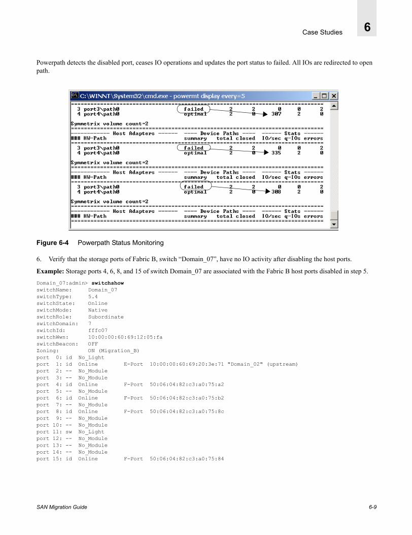
Case Studies 6
Powerpath detects the disabled port, ceases IO operations and updates the port status to failed. All IOs are redirected to open path.
Figure 6-4 Powerpath Status Monitoring
6. Verify that the storage ports of Fabric B, switch “Domain_07”, have no IO activity after disabling the host ports.
Example: Storage ports 4, 6, 8, and 15 of switch Domain_07 are associated with the Fabric B host ports disabled in step 5.
Domain_07:admin> switchshowswitchName: Domain_07switchType: 5.4switchState: OnlineswitchMode: NativeswitchRole: SubordinateswitchDomain: 7switchId: fffc07switchWwn: 10:00:00:60:69:12:05:faswitchBeacon: OFFZoning: ON (Migration_B)port 0: id No_Lightport 1: id Online E-Port 10:00:00:60:69:20:3e:71 "Domain_02" (upstream)port 2: -- No_Moduleport 3: -- No_Moduleport 4: id Online F-Port 50:06:04:82:c3:a0:75:a2port 5: -- No_Moduleport 6: id Online F-Port 50:06:04:82:c3:a0:75:b2port 7: -- No_Moduleport 8: id Online F-Port 50:06:04:82:c3:a0:75:8cport 9: -- No_Moduleport 10: -- No_Moduleport 11: sw No_Lightport 12: -- No_Moduleport 13: -- No_Moduleport 14: -- No_Moduleport 15: id Online F-Port 50:06:04:82:c3:a0:75:84
SAN Migration Guide 6-9

Case Studies 6
Example: Portperfshow Output(Note there is no IO activity on storage port 4, 6, 8, and 15.)
Domain_07:admin> portperfshow0 1 2 3 4 5 6 7 8 9 10 11 12 13 14 15 -------------------------------------------------------------------------------- 0 0 0 0 80 0 80 0 80 0 0 0 0 0 0 80
7. After verifying there is no activity on the storage ports, disable the ports and remove the storage port physical connections from the respective port by removing cable connections. Pull out the GBIC/SFP partially from its slot to maintain an orderly transition. Make sure these cables are tagged with proper identification before removal.
6.3.2. Fabric OS Compatibility LevelFabric B consists of three switches. Switch name “Domain_05” is a SilkWorm 3800 that we would like to keep intact. The remaining 1 Gbit/sec switches will be replaced. Test Case 1 and Test Case 2 illustrate an incremental switch migration, replacing one switch at a time for the purpose of simplifying and managing the entire migration process in a large and complex fabric environment.
The procedure below will be used:
1. Upgrade the Fabric OS to Fabric OS v2.6.0c or greater on all 1 Gbit switches, using the Firmware Download procedure detailed in Appendix B, Fabric OS Upgrade from 4.0.x TO 4.1.x.
2. Upgrade the Fabric OS to v3.0.2c or higher on the SilkWorm 3800 (and SilkWorm 3200, if applicable).
A fabric that has both SilkWorm 2000 and 3800 switches requires a minimum Fabric OS level of v2.6.0c and v3.0.2c. Failure to do so will result in fabric segmentation after Core PID format is set to 1. The reported error status is: unknown E-port - incompatible flow control parameters. It is always a best practice to upgrade Fabric OS to a most recent available version of Fabric OS.
Firmware Download Procedure
Refer to Downloading Fabric OS on page B-3 for detailed steps for this procedure.
Table 6-2
Fabric B Switch Model Recommended Minimum Fabric OS
Most recent Fabric OS release
Domian_05 SilkWorm 3800 v3.0.2c v3.1
Domain_02 SilkWorm 2400 v2.6.0c v2.6.1
Domain_07 SilkWorm 2250
SAN Migration Guide 6-10

Case Studies 6
6.3.3. Core PID Format Upgrade ProcedureObtain the current Core PID format setting information from the output of the ConfigShow command. If not already set to Core PID format-1 on the SilkWorm 2000 series and SilkWorm 3200 and 3800 switches.
Example:
Note: The fabric will remain segmented until the Core PID format on all switches of the Fabric B is set.
Repeat this step for the remaining switches of the SAN Fabric B. After all the switches are updated verify Fabric B is intact.
Domain05:admin> fabricshow
Switch ID Worldwide Name Enet IP Addr FC IP Addr Name--------------------------------------------------------------------------------------------------------- 2: fffc02 10:00:00:60:69:20:3e:71 192.168.162.56 0.0.0.0 "Domain_02" 5: fffc05 10:00:00:60:69:50:05:d3 192.168.162.253 0.0.0.0 "Domain_05" 7: fffc07 10:00:00:60:69:12:05:fa 192.168.162.113 0.0.0.0 "Domain_07"The Fabric has 3 switches
Domain05:admin> switchDisable
Domain05:admin> configureConfigure...Fabric parameters (yes, y, no, n): [no] y
Domain: (1..239) [5] BB credit: (1..27) [16] R_A_TOV: (4000..120000) [10000] E_D_TOV: (1000..5000) [2000] Data field size: (256..2112) [2112] Sequence Level Switching: (0..1) [0] Disable Device Probing: (0..1) [0] Suppress Class F Traffic: (0..1) [0] SYNC IO mode: (0..1) [0] VC Encoded Address Mode: (0..1) [0] Core Switch PID Format: (0..1) [0] 1 Per-frame Route Priority: (0..1) [1] Long Distance Fabric: (0..1) [0]Virtual Channel parameters (yes, y, no, n): [no] Zoning Operation parameters (yes, y, no, n): [no] RSCN Transmission Mode (yes, y, no, n): [no] NS Operation Parameters (yes, y, no, n): [no] Arbitrated Loop parameters (yes, y, no, n): [no] System services (yes, y, no, n): [no] Portlog events enable (yes, y, no, n): [no]Committing configuration...done.Domain_05:admin> switchEnable
Domain_05:admin> fabricshowSwitch ID Worldwide Name Enet IP Addr FC IP Addr Name------------------------------------------------------------------------- 5: fffc05 10:00:00:60:69:50:05:d3 192.168.162.253 0.0.0.0 >"Domain_05"
SAN Migration Guide 6-11
Case Studies 6
6.3.3.1. Core PID Format-1 and Switch Port AddressingFor a detailed discussion of the Core PID format, please refer to Understanding the Core PID Format on page 2-5 for details.
Table 6-3 Fabric B Consists of Three Switches
Table 6-5 PID Change on switch Storage “Domain_07” ports providing storage connectivity
6.3.3.2. Persistent Binding Consideration for Avoiding Rebooting of HostAIX, HP-UX and Solaris hosts are configured for persistent bindings by Port ID method in HBA configuration file. Any change in the 24-bit Port address invalidates the configuration file entry, prohibiting storage access. Since upgrading a switch Core PID format changes the 24-bit Port ID area byte field as described above for all storage ports, the corresponding host HBA configuration file persistent binding entries must be kept consistent with the Port ID. This is accomplished via one of the following methods:
• Matching the existing Persistent binding entry of the host to the modified Port ID.• Updating host configuration file.
Switch Name
Domain SilkWorm Model Connection type
Domain_05 5 3800 (2 Gbit/sec 16- port) Host
Domain_02 2 2400 (1 Gbit/sec 8- port) Core
Domain_07 7 2250 (1 Gbit/sec 16- port) Storage
Table 6-4 Port ID Update Map and Impact
Host Name Switch Port # Port_ID (format-0)
Port_ID (format-1)
Impact
HP_UX 2 12 02 none
Windows 2000 4 14 04 none
Solaris 6 16 06 none
AIX 8 18 (hex) 08 none
Host Name Switch Port # Port_ID (format-0)
Port_ID (format-1)
Impact
HP_UX Storage 4 14 04 * Refer to Persistent Binding Consideration for Avoiding Rebooting of Host on page 6-12
Solaris storage 6 16 06
AIX storage 8 18 08
Windows 2000 15 1F (hex) 0F
SAN Migration Guide 6-12
Case Studies 6
If you are replacing a 1 Gbit/sec 16-port switch (SilkWorm 2800) with a 2 Gbit/sec 16-port switch (SilkWorm 3800) and Port ID binding is utilized, then you must update the host configuration to re-define the hardware path to the storage device. In the case of a Solaris host, rebooting is also required. An alternate to Solaris host rebooting is available only if an existing 16-port switch is being replaced with higher port count SilkWorm 3900/12000 switch. In this case, the current persistent bindings entry consistency can be maintained by moving storage port of SilkWorm 2000 series port 0-15 to the matching address of upper port 16-31 of the SilkWorm 3900/12000 with an offset of 16 (see When Host Reboot Is Not An Option on page 2-7).
The following example shows that the current port binding entries for UNIX hosts connected to switch “Domain_07” physical ports 4, 6, and 8 are 071400, 071600 and 071800. When a 1 Gbit/sec switch is replaced with the 32-port SilkWorm 3900 with the same Domain ID of 07, these entries match with the upper ports 20 (14 hex), 22 (16 hex) and 24 (18 hex). Thus moving connections from the older 1 Gbit/sec switch ports 4, 6, and 8, to SilkWorm 3900 ports 20, 22, and 24 respectively, will eliminate the need of host configuration update.
6.3.4. Establishing Switch Replacement Order Fabric B has three SilkWorm switches, as shown in Figure 6-1 on page 6-2. If you are planning to replace all of the switches of a fabric when a fabric is offline and have no intention of re-using existing switches, you can skip both the Fabric OS upgrade and Core PID format steps entirely. However, if the fabric is in mix mode (SilkWorm 3800 and 2000 series) and you would like to keep SilkWorm 3800 (2 Gbit/sec switch), an incremental migration is more appropriate and recommended. After performing the Fabric OS upgrade and setting the Core PID format to 1, switches can be replaced or new Brocade switches can be added to the existing fabric without experiencing fabric segmentation.
If the persistent binding by PID is implemented as discussed above, the first switch you would like to successfully replace in the fabric is the one providing storage port connectivity (switch name “Domain_07”).
The SilkWorm 3800 switch providing host connectivity, has no persistent binding implication, therefore the host connection can remain on the same ports. The replacement of this switch to a higher port count 2 Gbit/sec SilkWorm 3900 is an optional step.
Table 6-6
Domain_07 (1Gbit) Persistent binding 24 bit Port_ID
1 Gbit switch port #
offset SilkWorm 3900 matching Persistent binding Port #
HP-UX Storage: 071400 4 +16 20
Solaris Storage: 071600 6 +16 22
AIX Storage: 071800 8 +16 24
Table 6-7 Replacement Order
Switch Name
Domain ID SilkWorm Model Connectivity Type
Replacement Order
Domain_05 5 3800 (2 Gbit/sec, 16-port)
Host Not being replaced
Domain_02 2 2400(1 Gbit/sec, 8-port)
Core 2
Domain_07 7 2250 (1 Gbit/sec, 16-port)
Storage 1
SAN Migration Guide 6-13

Case Studies 6
6.3.5. Zone Merge StrategyThere are several methods described in Propagating an Existing Zone Configuration on page 5-7 to import, merge or transfer an existing zone configuration to a displacement switch.
During Fabric B switch migration, the zoning configuration is propagated from SilkWorm 3800 switch which is part of existing fabric and not being replaced.
During Fabric A switch migration, since all switches are being replaced, at least one existing 1 Gbit/sec switch must be upgraded to form a fabric with the SilkWorm 3900, so that the active configuration can be propagated during fabric build. See Propagating an Existing Zone Configuration on page 5-7.
6.3.6. SilkWorm 3900 Switch PreparationA switch replacement requires the transfer of existing switch parameters to the replacement switch. Each switch in the fabric is assigned a unique Domain ID used in forming 24-bit port address. A switch providing storage port connectivity must assume the same Domain ID of the switch it is replacing in order to match the persistent binding entries, otherwise a host configuration update may be required. A switch must also meet licensing requirements to enable additional software features.
Preparing a SilkWorm 3900 switch to replace a 1Gbit/sec SilkWorm 2250 - Name “Domain_07”
Table 6-8 Transferring Current Parameters to SilkWorm 3900
1. IP address 192.168.162.113
2. User specific settings password, etc.
3. Switch name Domain_07
4. Firmware verification 4.0.2b or higher
5. License verification Verify license key requirements for required software packages
6. Domain setup 07
7. Switch Configure Parameters user define parameters other than default: Port configurationFabric WatchSNMP etc.
SAN Migration Guide 6-14
Case Studies 6
1. Setting up the IP address from Terminal port. Make the appropriate connection to terminal port and access via properly configured Terminal.
Figure 6-5 Setting an IP Address
Note: If assigning the SilkWorm 3900 the same IP address as the SilkWorm 2250, there will be two switches with the same IP address. In order to access the SilkWorm 3900 via Ethernet, the Ethernet connection on existing SilkWorm 2250 must be disconnected. A temporary unused interim IP address may assigned to the SilkWorm 2250 in the interim.
2. After an IP address is assigned to a switch, open a telnet session on the SilkWorm 3900 switch, name “swd41”. Set the name, password, Domain ID, and switch configuration identical to the switch being replaced.
Example: Setting Switch Name, Password, and Configuration
swd41:admin> switchname "Domain_D7"Committing configuration...Done.
Domain_D7:admin> passwdChanging password for adminEnter new password:Re-type new password:
Domain_D7:admin> date "0425132703" ( "mmddhhmmyy")Fri Apr 25 13:27:00 UTC 2003
Domain_D7:admin> licenseshowbQeRbRbRQRqRfSc1: Web license Zoning license Fabric license Remote Switch license Extended Fabric license Fabric Watch license Performance Monitor license Trunking license * Please note the new Trunking feature licenseing requirement
SAN Migration Guide 6-15
Case Studies 6
3. Verify the version of Fabric OS on the SilkWorm 3900, it must be Fabric OS v4.0.2b or later. It is recommended to upgrade the Fabric OS to the most recent available Fabric OS version.
Example: Verifying Fabric OS version
Domain_D7:admin> versionKernel: 2.4.2Fabric OS: v4.0.2bMade on: Wed Oct 30 01:43:49 2002Flash: Thu Oct 31 21:12:44 2002BootProm: 3.1.18
4. Setup switch Domain ID and verify rest of the switch configuration parameters.
Warning: This step requires the switch to be disabled.
Note: When SilkWorm 3900 is being prepared to displace an existing 1 Gbit/sec switch, the displaced switch Domain ID is assigned to the SilkWorm 3900. When adding a new switch to an existing fabric, make sure the new switch is assigned a unique Domain ID (duplicate Domain IDs are not permitted in a fabric).
Example: Configuring the SilkWorm 3900
Domain_D7:admin> switchdisableDomain_D7:admin> configure
Configure...
Fabric parameters (yes, y, no, n): [no] y
Domain: (1..239) [1] 7 R_A_TOV: (4000..120000) [10000] E_D_TOV: (1000..5000) [2000] Data field size: (256..2112) [2112] Sequence Level Switching: (0..1) [0] Disable Device Probing: (0..1) [0] Suppress Class F Traffic: (0..1) [0] VC Encoded Address Mode: (0..1) [0] Per-frame Route Priority: (0..1) [0] Long Distance Fabric: (0..1) [0] BB credit: (1..16) [16]
Virtual Channel parameters (yes, y, no, n): [no] Zoning Operation parameters (yes, y, no, n): [no] RSCN Transmission Mode (yes, y, no, n): [no] NS Operation Parameters (yes, y, no, n): [no] Arbitrated Loop parameters (yes, y, no, n): [no] System services (yes, y, no, n): [no] Portlog events enable (yes, y, no, n): [no]done.Domain_D7:admin> switchEnable
SAN Migration Guide 6-16

Case Studies 6
5. Check the SilkWorm 3900 port configuration setup. They are setup for Auto-Negotiation (AN) by default but the ports can be setup to a specific speed.
Example: Checking SilkWorm 3900 Port Configuration
Domain_D7:admin> portcfgshowPort 0 1 2 3 4 5 6 7 8 9 10 11 12 13 14 15----------------+--+--+--+--+----+--+--+--+----+--+--+--+----+--+--+--Speed AN AN AN AN AN AN AN AN AN AN AN AN AN AN AN ANTrunk Port ON ON ON ON ON ON ON ON ON ON ON ON ON ON ON ONLong Distance .. .. .. .. .. .. .. .. .. .. .. .. .. .. .. ..C Link Init .. .. .. .. .. .. .. .. .. .. .. .. .. .. .. ..Locked L_Port .. .. .. .. .. .. .. .. .. .. .. .. .. .. .. ..Locked G_Port .. .. .. .. .. .. .. .. .. .. .. .. .. .. .. ..Disabled E_Port .. .. .. .. .. .. .. .. .. .. .. .. .. .. .. ..cast LoopBack .. .. .. .. .. .. .. .. .. .. .. .. .. .. .. ..Delay Flogi .. .. .. .. .. .. .. .. .. .. .. .. .. .. .. ..
Port 16 17 18 19 20 21 22 23 24 25 26 27 28 29 30 31----------------+--+--+--+--+----+--+--+--+----+--+--+--+----+--+--+--Speed AN AN AN AN AN AN AN AN AN AN AN AN AN AN AN ANTrunk Port ON ON ON ON ON ON ON ON ON ON ON ON ON ON ON ONLong Distance .. .. .. .. .. .. .. .. .. .. .. .. .. .. .. ..C Link Init .. .. .. .. .. .. .. .. .. .. .. .. .. .. .. ..Locked L_Port .. .. .. .. .. .. .. .. .. .. .. .. .. .. .. ..Locked G_Port .. .. .. .. .. .. .. .. .. .. .. .. .. .. .. ..Disabled E_Port .. .. .. .. .. .. .. .. .. .. .. .. .. .. .. ..cast LoopBack .. .. .. .. .. .. .. .. .. .. .. .. .. .. .. ..Delay Flogi .. .. .. .. .. .. .. .. .. .. .. .. .. .. .. ..
6. Verify switch port speed setup and change if required.
Guideline: Switch ports can be locked for a specific speed if required. The default is Auto-Negotiation.
Example: Verifying Switch Speed
Domain_D7:admin> switchcfgspeed
Usage: switchCfgSpeed Speed_Level Speed_Level: 0 - Auto Negotiate 1 - 1Gbps 2 - 2Gbps
7. Verify the switch error/fault policies and make changes if required, using the command SwitchstatusPolicySet.
Example: Verifying Switch Error and Fault Policies
Domain_D7:admin> switchStatusPolicyShow Down Marginal -------------------------------------------------------------- FaultyPorts 2 1 MissingSFPs 0 0 PowerSupplies 2 1 Temperatures 2 1 Fans 2 1 PortStatus 0 0 ISLStatus 0 0
SAN Migration Guide 6-17
Case Studies 6
8. Verify the SNMP settings and modify if required, using the command agtcfgSet.
Example: Verify SNMP Settings
Domain_D7:admin> agtcfgshow sysDescr = Fibre Channel Switch. sysLocation = End User Premise sysContact = Field Support. swEventTrapLevel = 0 authTraps = 0 (OFF)SNMPv1 community and trap recipient configuration: Community 1: Secret C0de (rw) No trap recipient configured yet Community 2: OrigEquipMfr (rw) No trap recipient configured yet Community 3: private (rw) No trap recipient configured yet Community 4: public (ro) No trap recipient configured yet Community 5: common (ro) No trap recipient configured yet Community 6: FibreChannel (ro) No trap recipient configured yet
SNMP access list configuration:Entry 0: No access host configured yetEntry 1: No access host configured yetEntry 2: No access host configured yetEntry 3: No access host configured yetEntry 4: No access host configured yetEntry 5: No access host configured yet
9. The Configshow command provides the entire switch parameter configuration listing which can be saved and retrieved on a server.
Example: Configshow Output
Domain_D7:admin> configshowRSCN.end-device.TransmissionMode:0alpaList:1diag.loopID:125diag.mode.burnin:0diag.mode.esd:0diag.mode.lab:0diag.mode.mfg:0diag.postDisable:0diag.retryDisable:0diag.script.SWITCH.BURNIN:switchburnin.shdiag.script.SWITCH.POST1:switchpost1.shdiag.script.SWITCH.POST2:switchpost2.shdiag.test.crossPort.passes:5000diag.test.passes:0diag.test.portLoopback.passes:1000diag.test.silkScreen.passes:180diag.test.spinSilk.passes:120ether.link.mode:AUTOfabric.domain:7fabric.ops.BBCredit:16fabric.ops.E_D_TOV:2000fabric.ops.R_A_TOV:10000fabric.ops.dataFieldSize:2112fabric.ops.mode.fcpProbeDisable:0fabric.ops.mode.isolate:0
SAN Migration Guide 6-18

Case Studies 6
fabric.ops.mode.longDistance:0fabric.ops.mode.noClassF:0fabric.ops.mode.tachyonCompat:0fabric.ops.mode.unicastOnly:0fabric.ops.mode.useCsCtl:0fabric.ops.mode.vcEncode:0fabric.ops.vc.class.2:2fabric.ops.vc.class.3:3fabric.ops.vc.config:0xc0fabric.ops.vc.linkCtrl:0fabric.ops.vc.multicast:7fc4.fcIp.address:0.0.0.0fc4.fcIp.mask:0.0.0.0fc4.fcp.productId:FC Switchfc4.fcp.vendorId:BROCADEfcAL.alwaysSendRSCN:0fcAL.fanFrameDisable:1fcAL.openSendCLS:0fcAL.useAltBBCredit:0flannel.ops.frameColMethod:pilingflannel.ops.openBBCredit:4gen.fabos:0gen.zone:0http.javaplugin.homeURL:http://java.sun.com/products/pluginhttp.javaplugin.version:1,2,2lcdContrast:128lcdContrast.orange:208ms.PlatEnable:1ms.TDEnable:0ns.prezonemode:0oemLogo:0portCfg:0, 0x10000000; 1, 0x10000000; 2, 0x10000000; 3, 0x10000000; 4, 0x10000000; 5, 0x10000000; 6, 0x10000000; 7, 0x10000000; 8, 0x10000000; 9, 0x10000000; 10, 0x10000000; 11, 0x10000000; 12, 0x10000000; 13, 0x10000000; 14, 0x10000000; 15, 0x10000000; 16, 0x10000000; 17, 0x10000000; 18, 0x10000000; 19, 0x10000000; 20, 0x10000000; 21, 0x10000000; 22, 0x10000000; 23, 0x10000000; 24, 0x10000000; 25, 0x10000000; 26, 0x10000000; 27, 0x10000000; 28, 0x10000000; 29, 0x10000000; 30, 0x10000000; 31, 0x10000000; 32, 0x10000000; 33, 0x10000000; 34, 0x10000000; 35, 0x10000000; 36, 0x10000000; 37, 0x10000000; 38, 0x10000000; 39, 0x10000000; 40, 0x10000000; 41, 0x10000000; 42, 0x10000000; 43, 0x10000000; 44, 0x10000000; 45, 0x10000000; 46, 0x10000000; 47, 0x10000000; 48, 0x10000000; 49, 0x10000000; 50, 0x10000000; 51, 0x10000000; 52, 0x10000000; 53, 0x10000000; 54, 0x10000000; 55, 0x10000000; 56, 0x10000000; 57, 0x10000000; 58, 0x10000000; 59, 0x10000000; 60, 0x10000000; 61, 0x10000000; 62, 0x10000000; 63, 0x10000000;quickLoop.holdOpenInit:0quickLoop.noAlpaZero:0quickLoop.peerWWN:00:00:00:00:00:00:00:00quickLoop.portBitmap:0x0000000000000000quickLoop.softInit:0rlsDisable:1route.delayReroute:0route.embeddedPortBcast:1route.stickyRoutes:0rpc.rapid:1rpc.rstatd:0rpc.rusersd:0shell.delete:0shell.quiet:0snmp.accessList.0.address:0.0.0.0snmp.accessList.0.rw:1snmp.accessList.1.address:0.0.0.0snmp.accessList.1.rw:1snmp.accessList.2.address:0.0.0.0
SAN Migration Guide 6-19
Case Studies 6
snmp.accessList.2.rw:1snmp.accessList.3.address:0.0.0.0snmp.accessList.3.rw:1snmp.accessList.4.address:0.0.0.0snmp.accessList.4.rw:1snmp.accessList.5.address:0.0.0.0snmp.accessList.5.rw:1snmp.agtParty.0.address:0.0.0.0snmp.agtParty.0.authPrivSecret:Secret C0desnmp.agtParty.0.index:1snmp.agtParty.0.port:162snmp.agtParty.1.address:0.0.0.0snmp.agtParty.1.authPrivSecret:OrigEquipMfrsnmp.agtParty.1.index:2snmp.agtParty.1.port:162snmp.agtParty.2.address:0.0.0.0snmp.agtParty.2.authPrivSecret:privatesnmp.agtParty.2.index:3snmp.agtParty.2.port:162snmp.agtParty.3.address:0.0.0.0snmp.agtParty.3.authPrivSecret:publicsnmp.agtParty.3.index:4snmp.agtParty.3.port:162snmp.agtParty.4.address:0.0.0.0snmp.agtParty.4.authPrivSecret:commonsnmp.agtParty.4.index:5snmp.agtParty.4.port:162snmp.agtParty.5.address:0.0.0.0snmp.agtParty.5.authPrivSecret:FibreChannelsnmp.agtParty.5.index:6snmp.agtParty.5.port:162snmp.authentTraps:0snmp.mibCap:103snmp.swEventTrapLevel:0snmp.sysContact:Field Support.snmp.sysDescription:Fibre Channel Switch.snmp.sysLocation:End User Premisesnmp.sysObjectID:1588.2.1.1.1switch.interopMode:0switch.largeEntry.cap:0switch.status.policy.Fans.down:2switch.status.policy.Fans.marginal:1switch.status.policy.FaultyPorts.down:2switch.status.policy.FaultyPorts.marginal:1switch.status.policy.ISLStatus.down:0switch.status.policy.ISLStatus.marginal:0switch.status.policy.MissingSFPs.down:0switch.status.policy.MissingSFPs.marginal:0switch.status.policy.PortStatus.down:0switch.status.policy.PortStatus.marginal:0switch.status.policy.PowerSupplies.down:2switch.status.policy.PowerSupplies.marginal:1switch.status.policy.Temperatures.down:2switch.status.policy.Temperatures.marginal:1thresh.thad:1xlativeModeDisable:0zoning.check.nodeNameDisabled:0zoning.standardMode:0zoning.transactionFlag:0:Licenses:bQeRbRbRQRqRfSc1(END)
SAN Migration Guide 6-20

Case Studies 6
10. Clear the zoning configuration.
Clear all active and/or inactive Zone configurations on the SilkWorm 3900 switch. Since this switch is going to join an existing fabric, the Zone configuration will be propagated from the existing fabric during fabric rebuild process.
Note: This step is necessary for successful fabric re-build. If any zone configuration is left on the SilkWorm 3900, the failure to merge zones between two different zone configurations during the fabric rebuild process could result in a fabric segmentation or a confusing zone configuration.
Example: Clearing Zoning Configuration
Domain_D7:admin> cfgclearDo you really want to clear all configurations? (yes, y, no, n): [no] yDomain_D7:admin> cfgsaveUpdating flash ...Domain_D7:admin> cfgshowDefined configuration: no configuration defined
Effective configuration: no configuration in effect
6.4. Test Cases 1-6This section describes the following cases:
• Case 1: Direct Replacement of a 1 Gbit/sec Edge Switch Connecting Storage• Case 2: Direct Replacement of a 1 Gbit/sec Core Switch with a SilkWorm 3900• Case 3: Adding a New SilkWorm 3900 to Fabric B• Case 4: Collapsing Two 1 Gbit/sec Lower Port Count Switches Providing Storage Connectivity into a Single SilkWorm
3900• Case 5: Collapsing Two 1 Gbit/sec Lower Port Count Switches Providing Host Connectivity into a Single SilkWorm 3900• Case 6: Replacing a Lower Port Count Core Switch with High Performance SilkWorm 12000
Figure 6-6 Replacing existing SilkWorm 2250 with SilkWorm 3900 “Domain_07”
SD
Si lkWorm 2 80 0
1 3 5 7 9 1 1 13 1 5
0 2 4 6 8 1 0 12 1 4
1
2
1
SD
Sil kWorm 21000 2 4 6
1 3 5 7
SD
5
(SW-3900, 32 port )(SW-2250 ,16 port)
Fabric-B
Domain_ 05
Domain_ 02
Domain_ 07
Domain_ 02(SW-3900 32 port)
(SW-3800 16 port)
SAN Migration Guide 6-21

Case Studies 6
6.4.1. Case 1: Direct Replacement of a 1 Gbit/sec Edge Switch Connecting Storage
Procedure1. Disable existing the SilkWorm 2250 switch name “Domain_07”.
2. Turn the switch power off.
3. Disconnect all ISL(s) from this switch.
4. The Fabric B must show only two switches.
Example: Fabricshow on Fabric B
Domain_02:admin> fabricshowSwitch ID Worldwide Name Enet IP Addr FC IP Addr Name------------------------------------------------------------------------- 2: fffc02 10:00:00:60:69:20:3e:71 192.168.162.56 0.0.0.0 "Domain_02" 5: fffc05 10:00:00:60:69:50:05:d3 192.168.162.253 0.0.0.0 >"Domain_05"
5. Mount the newly prepared SilkWorm 3900 switch in the vicinity of the older switch, considering the length of the existing cable.
Note: The length of cables must be adequate to reach the SilkWorm 3900 ports. A short cable will result in unnecessary delay and cable replacement cost.
Note: The SilkWorm 3900 has SFP based ports that require an LC type mating cable connector. When moving a GBIC based SilkWorm 2000 series switch, a conversion from SC to LC is required.
Note: Extending an Inter Link Switch (ISL) between a SilkWorm 3900 and a SilkWorm 2000 series switch also requires an SC-LC type cable until all Fabric B switches are migrated to SFP based 2 Gbit/sec ports.
6. Apply power to the SilkWorm 3900.
7. Establish an Ethernet connection to the SilkWorm 3900.
8. Telnet to the switch and verify the switch is online.
9. Add Inter Switch Links (ISLs) from the SilkWorm 3900 to the switches in Fabric B.
10. Ensure the remaining switches in the fabric are also powered up.
11. Verify the SilkWorm 3900 has successfully joined the existing Fabric B.
Example: Verifying Fabric B
Domain_D7:admin> fabricshowSwitch ID Worldwide Name Enet IP Addr FC IP Addr Name--------------------------------------------------------------------------------------------------------- 2: fffc02 10:00:00:60:69:20:3e:71 192.168.162.56 0.0.0.0 "Domain_02" 5: fffc05 10:00:00:60:69:50:05:d3 192.168.162.253 0.0.0.0 >"Domain_05" 7: fffc07 10:00:00:60:69:90:04:2c 192.168.162.113 0.0.0.0 "Domain_D7" ( SW-3900)
SAN Migration Guide 6-22

Case Studies 6
Guideline: The SilkWorm 3900 may not be able join the existing Fabric B for one or more reasons listed below:- Zone configuration conflict – the zone configuration on the SilkWorm 3900 is not cleared- The Core PID on the existing Fabric B is not upgraded - The Fabric OS version is incompatible- The switch fabric parameter setting on SilkWorm 3900 is incorrect- The cable is faulty
12. Verify the Fabric B zone configuration is on the SilkWorm 3900.
Example: Verifying the Configuration on the SilkWorm 3900
Domain_D7:admin> CfgShowEffective configuration: cfg: Migration_B zone: Portzone_HPUX_hba00 7,4 5,2 zone: Portzone_Solaris_hba1 5,6 7,6 zone: portzone_AIX22_hba1 5,8 7,8 zone: portzone_w2k_hba1 5,4 7,15
13. Modify port based Zoning to reflect the correct switch port.
6.4.1.1. Modify Zoning Using Brocade Web Tools1. Open Web Tools by providing an IP address of a switch on Fabric B and click the Zone Admin button.
Figure 6-7 Web Tools Fabric View
SAN Migration Guide 6-23

Case Studies 6
2. Examine Zone sets of existing Configuration name “Migration_B” from the Config tab.
Figure 6-8 Web Tools Zone Admin
3. Select the appropriate zone from the Zone tab and modify the zone by adding or removing members of that zone as required.
zone: Portzone_HPUX_hba00 – remove Domain 7, port 4 and add Doamin 7, port 20zone: Portzone_Solaris_hba1- remove Domain 7, port 6 and add Doamin 7, port 22zone: portzone_AIX22_hba1- remove Domain 7, port 8 and add Doamin 7, port 24zone: portzone_w2k_hba1- remove Domain 7, port 15 and add Doamin 7, port 31
SAN Migration Guide 6-24

Case Studies 6
Figure 6-9 Zone Admin - Zone Tab
4. From the Config tab – First save, then enable the configuration to make the change effective.
6.4.1.2. Moving Device Connections to the SilkWorm 3900Move all device port connections from the replaced SilkWorm 2050 to the SilkWorm 3900 as per the modified zoning configuration and verify all devices are logged in properly. A cable conversion is required here from SC-to-LC (see Cabling on page 2-9).
Example: SilkWorm 3900 with assigned Domain_ID 07
Domain_D7:admin> switchshowswitchName: Domain_D7switchType: 12.1switchState: OnlineswitchRole: SubordinateswitchDomain: 7switchId: fffc07switchWwn: 10:00:00:60:69:90:04:2cswitchBeacon: OFF
Port Gbic Speed State========================= 0 id N2 No_Light 1 id N1 Online E-Port 10:00:00:60:69:20:3e:71 "Domain_02" (upstream) 2 id N2 No_Light 3 id N2 No_Light 4 id N2 No_Light 5 id N2 No_Light 6 id N2 No_Light 7 id N2 No_Light
SAN Migration Guide 6-25
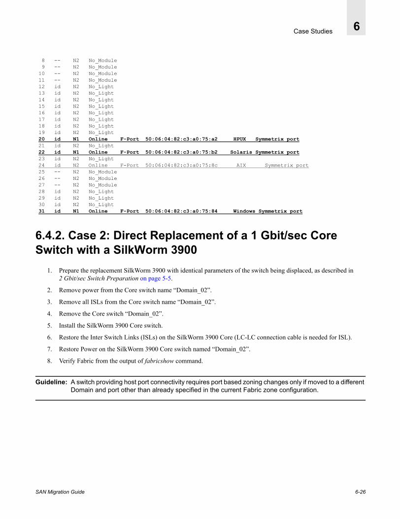
Case Studies 6
8 -- N2 No_Module 9 -- N2 No_Module 10 -- N2 No_Module 11 -- N2 No_Module 12 id N2 No_Light 13 id N2 No_Light 14 id N2 No_Light 15 id N2 No_Light 16 id N2 No_Light 17 id N2 No_Light 18 id N2 No_Light 19 id N2 No_Light 20 id N1 Online F-Port 50:06:04:82:c3:a0:75:a2 HPUX Symmetrix port 21 id N2 No_Light 22 id N1 Online F-Port 50:06:04:82:c3:a0:75:b2 Solaris Symmetrix port 23 id N2 No_Light 24 id N2 Online F-Port 50:06:04:82:c3:a0:75:8c AIX Symmetrix port 25 -- N2 No_Module 26 -- N2 No_Module 27 -- N2 No_Module 28 id N2 No_Light 29 id N2 No_Light 30 id N2 No_Light 31 id N1 Online F-Port 50:06:04:82:c3:a0:75:84 Windows Symmetrix port
6.4.2. Case 2: Direct Replacement of a 1 Gbit/sec Core Switch with a SilkWorm 3900
1. Prepare the replacement SilkWorm 3900 with identical parameters of the switch being displaced, as described in 2 Gbit/sec Switch Preparation on page 5-5.
2. Remove power from the Core switch name “Domain_02”.
3. Remove all ISLs from the Core switch name “Domain_02”.
4. Remove the Core switch “Domain_02”.
5. Install the SilkWorm 3900 Core switch.
6. Restore the Inter Switch Links (ISLs) on the SilkWorm 3900 Core (LC-LC connection cable is needed for ISL).
7. Restore Power on the SilkWorm 3900 Core switch named “Domain_02”.
8. Verify Fabric from the output of fabricshow command.
Guideline: A switch providing host port connectivity requires port based zoning changes only if moved to a different Domain and port other than already specified in the current Fabric zone configuration.
SAN Migration Guide 6-26

Case Studies 6
6.4.3. Bringing Fabric B Online1. Re-establish the host connections on the SilkWorm 3800 switch named “Domain_05” (insert the SFP into the port
slots and make sure the cable connectors are inserted).
Example: SwitchShow of SilkWorm 3800
switchName: Domain_05switchType: 9.1switchState: OnlineswitchMode: NativeswitchRole: PrincipalswitchDomain: 5switchId: fffc05switchWwn: 10:00:00:60:69:50:05:d3switchBeacon: OFFZoning: ON (Migration_B)port 0: id N2 No_Lightport 1: id N1 Online E-Port 10:00:00:60:69:20:3e:71 "Domain_02" (downstream)port 2: id N1 Online F-Port 50:06:0b:00:00:08:fd:e8port 3: -- N2 No_Moduleport 4: id N1 Online F-Port 10:00:00:00:c9:21:9c:79port 5: id N2 No_Lightport 6: id N2 Online F-Port 10:00:00:00:c9:2f:23:bfport 7: -- N2 No_Moduleport 8: id N2 Online F-Port 10:00:00:00:c9:2f:1d:e5port 9: id N2 No_Lightport 10: -- N2 No_Moduleport 11: -- N2 No_Moduleport 12: -- N2 No_Moduleport 13: -- N2 No_Moduleport 14: -- N2 No_Moduleport 15: -- N2 No_Module
2. Restoring Powerpath. Upon detecting path availability, EMC Powerpath automatically restores the path and IO activity.
Figure 6-10 Powerpath status Monitoring
SAN Migration Guide 6-27
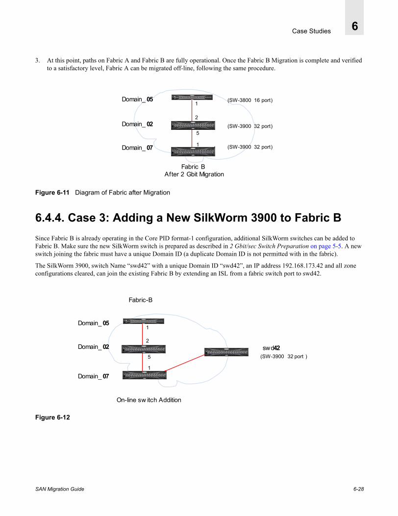
Case Studies 6
3. At this point, paths on Fabric A and Fabric B are fully operational. Once the Fabric B Migration is complete and verified to a satisfactory level, Fabric A can be migrated off-line, following the same procedure.
Figure 6-11 Diagram of Fabric after Migration
6.4.4. Case 3: Adding a New SilkWorm 3900 to Fabric BSince Fabric B is already operating in the Core PID format-1 configuration, additional SilkWorm switches can be added to Fabric B. Make sure the new SilkWorm switch is prepared as described in 2 Gbit/sec Switch Preparation on page 5-5. A new switch joining the fabric must have a unique Domain ID (a duplicate Domain ID is not permitted with in the fabric).
The SilkWorm 3900, switch Name “swd42” with a unique Domain ID “swd42”, an IP address 192.168.173.42 and all zone configurations cleared, can join the existing Fabric B by extending an ISL from a fabric switch port to swd42.
Figure 6-12
1
2
1
5
Fabric B After 2 Gbit Migration
Domain_ 05
Domain_ 02
Domain_ 07
(SW-3900 32 port)
(SW-3900 32 port)
(SW-3800 16 port)
1
2
1
5 (SW-3900 32 port )
Fabric-B
On-line sw itch Addition
Domain_ 05
Domain_ 02
Domain_ 07
swd42
SAN Migration Guide 6-28
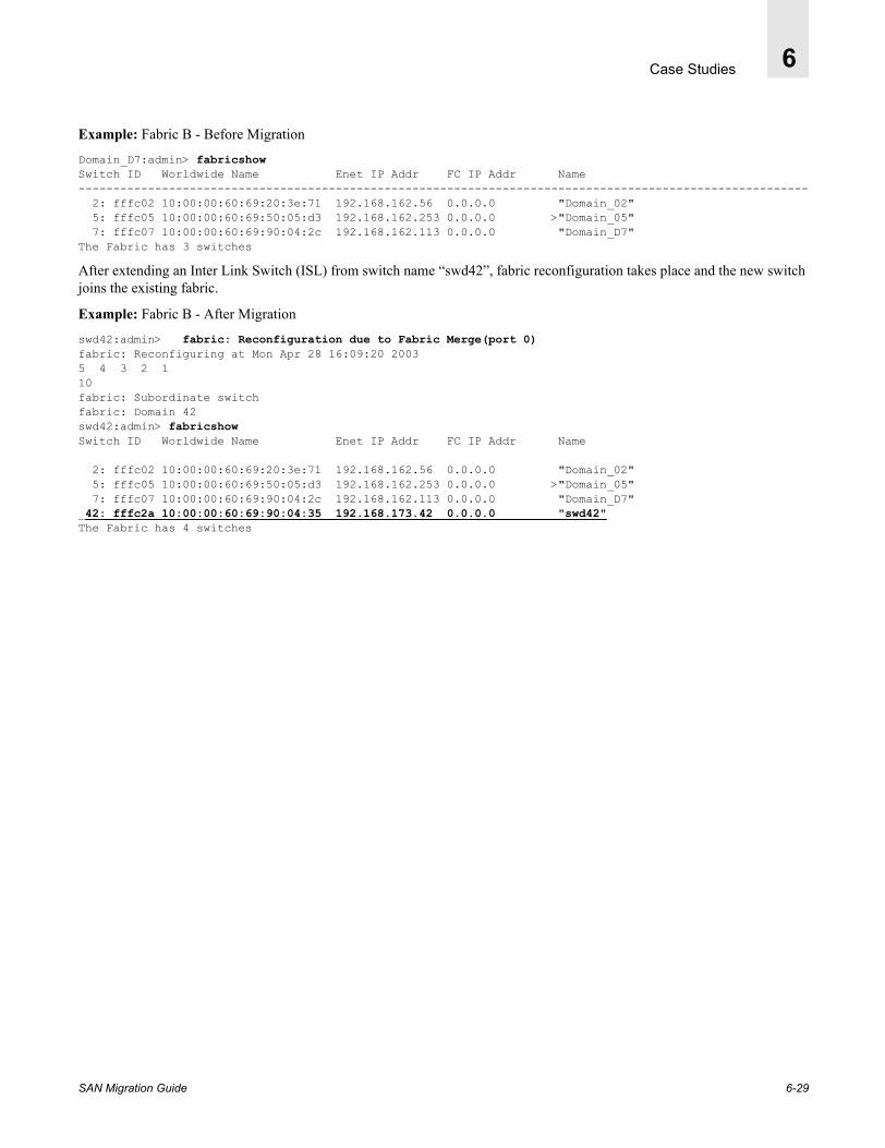
Case Studies 6
Example: Fabric B - Before Migration
Domain_D7:admin> fabricshowSwitch ID Worldwide Name Enet IP Addr FC IP Addr Name--------------------------------------------------------------------------------------------------------- 2: fffc02 10:00:00:60:69:20:3e:71 192.168.162.56 0.0.0.0 "Domain_02" 5: fffc05 10:00:00:60:69:50:05:d3 192.168.162.253 0.0.0.0 >"Domain_05" 7: fffc07 10:00:00:60:69:90:04:2c 192.168.162.113 0.0.0.0 "Domain_D7"The Fabric has 3 switches
After extending an Inter Link Switch (ISL) from switch name “swd42”, fabric reconfiguration takes place and the new switch joins the existing fabric.
Example: Fabric B - After Migration
swd42:admin> fabric: Reconfiguration due to Fabric Merge(port 0)fabric: Reconfiguring at Mon Apr 28 16:09:20 20035 4 3 2 110fabric: Subordinate switchfabric: Domain 42swd42:admin> fabricshowSwitch ID Worldwide Name Enet IP Addr FC IP Addr Name
2: fffc02 10:00:00:60:69:20:3e:71 192.168.162.56 0.0.0.0 "Domain_02" 5: fffc05 10:00:00:60:69:50:05:d3 192.168.162.253 0.0.0.0 >"Domain_05" 7: fffc07 10:00:00:60:69:90:04:2c 192.168.162.113 0.0.0.0 "Domain_D7" 42: fffc2a 10:00:00:60:69:90:04:35 192.168.173.42 0.0.0.0 "swd42"The Fabric has 4 switches
SAN Migration Guide 6-29
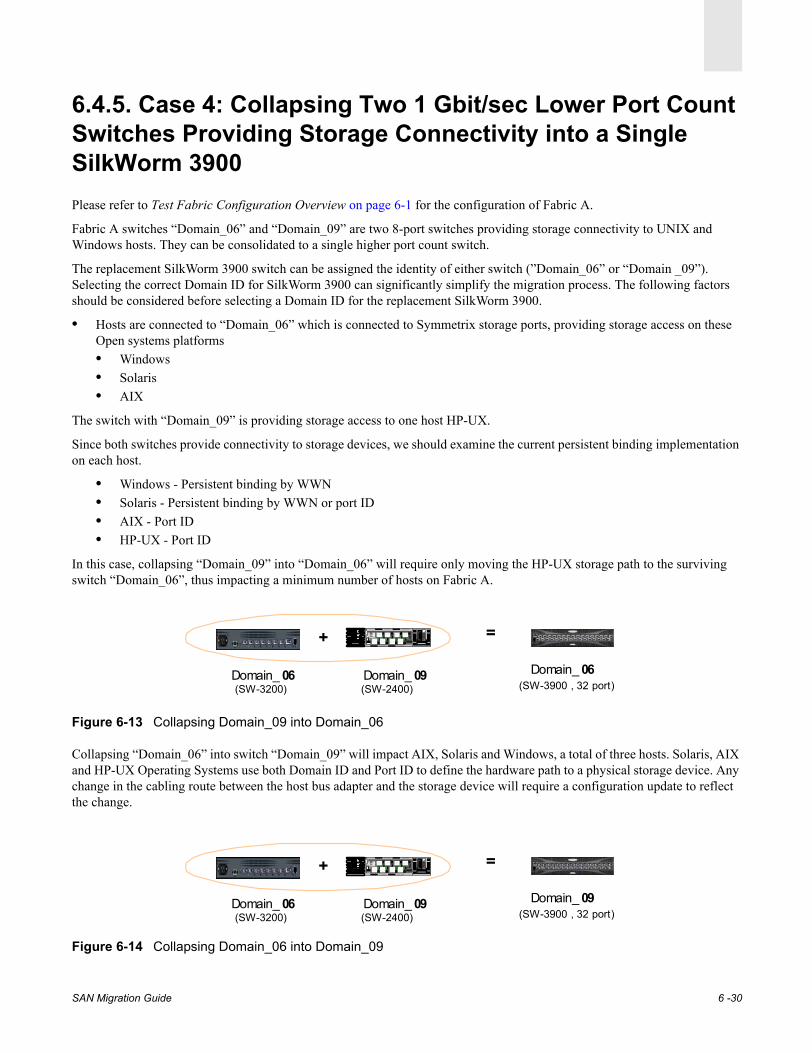
6.4.5. Case 4: Collapsing Two 1 Gbit/sec Lower Port Count Switches Providing Storage Connectivity into a Single SilkWorm 3900Please refer to Test Fabric Configuration Overview on page 6-1 for the configuration of Fabric A.
Fabric A switches “Domain_06” and “Domain_09” are two 8-port switches providing storage connectivity to UNIX and Windows hosts. They can be consolidated to a single higher port count switch.
The replacement SilkWorm 3900 switch can be assigned the identity of either switch (”Domain_06” or “Domain _09”). Selecting the correct Domain ID for SilkWorm 3900 can significantly simplify the migration process. The following factors should be considered before selecting a Domain ID for the replacement SilkWorm 3900.
• Hosts are connected to “Domain_06” which is connected to Symmetrix storage ports, providing storage access on these Open systems platforms• Windows• Solaris • AIX
The switch with “Domain_09” is providing storage access to one host HP-UX.
Since both switches provide connectivity to storage devices, we should examine the current persistent binding implementation on each host.
• Windows - Persistent binding by WWN• Solaris - Persistent binding by WWN or port ID• AIX - Port ID• HP-UX - Port ID
In this case, collapsing “Domain_09” into “Domain_06” will require only moving the HP-UX storage path to the surviving switch “Domain_06”, thus impacting a minimum number of hosts on Fabric A.
Figure 6-13 Collapsing Domain_09 into Domain_06
Collapsing “Domain_06” into switch “Domain_09” will impact AIX, Solaris and Windows, a total of three hosts. Solaris, AIX and HP-UX Operating Systems use both Domain ID and Port ID to define the hardware path to a physical storage device. Any change in the cabling route between the host bus adapter and the storage device will require a configuration update to reflect the change.
Figure 6-14 Collapsing Domain_06 into Domain_09
Domain_ 06(SW-3200)
SD
Sil kWorm 21000 2 4 6
1 3 5 7
SD
Domain_ 09(SW-2400)
+ =
Domain_ 06(SW-3900 , 32 port)
Domain_ 06(SW-3200)
SD
Sil kWorm 21000 2 4 6
1 3 5 7
SD
Domain_ 09(SW-2400)
+ =
Domain_ 09(SW-3900 , 32 port)
SAN Migration Guide 6 -30

6.4.5.1. Collapsing Storage Port Switch “Domain_9” into “Domain_06”Follow the steps described in Chapter 3, Developing a Migration Strategy for preparing Fabric A and the SilkWorm 3900 for 2 Gbit/sec Migration.
A detailed procedure of fabric assessment, preparation, and migration is given in Prepare to Migrate (Example Fabric B) on page 6-7. Apply the same process to Fabric A migration.
Step 1: Summary of Fabric A Migration Preparation Steps1. SAN Fabric B paths are open and fully operational.
2. SAN Fabric A is off-line.
3. There are no active IOs (all IOs are directed to Fabric B).
4. All Fabric A switches are upgraded to recommended Fabric OS level.
5. The Core PID format is set to 1 on all switches in Fabric A.
6. The replacement SilkWorm 3900 has been configured offline to replace the existing 1 Gbit/sec switch.
7. Disable the existing SilkWorm 3200 switch name “Domain_06”.
8. Turn the switch power off.
9. Disconnect all ISL(s) from this switch.
10. Mount the newly prepared SilkWorm 3900 switch in the vicinity of the older switch, considering the length of the existing cable.
11. Mount the SilkWorm 3900 appropriately on the rack.
12. Apply power to the SilkWorm 3900.
13. Establish an Ethernet connection to the SilkWorm 3900. Open a Telnet session to the switch and verify it is online.
14. Add Inter Switch Links (ISL) from the SilkWorm 3900 to the switches in Fabric A. Ensure the remaining switches in the fabric are also powered up.
15. The SilkWorm 3900 will be able to successfully join the existing fabric.
16. Verify the fabric.
Guideline: The cable length must be adequate to reach the ports on the SilkWorm 3900. A short cable will result in unnecessary delay and cable replacement cost.
Guideline: The SilkWorm 3900 has SFP based ports that require an LC type mating cable connector. When moving GBIC based SilkWorm 2000 series, a connector conversion from SC-to-LC is required.
Guideline: Extending an Inter Link Switch (ISL) between the SilkWorm 3900 and the SilkWorm 2000 series switch also requires an SC-LC type cable until all switches in Fabric B have been migrated.
SAN Migration Guide 6 -31

Step 2: Updating Fabric A Zone Configuration In this case, for the HP-UX storage port Domain ID, change from “Domain_09” to “Domain_06” because of the elimination of the SilkWorm 2400 “Domain_09”. The port connectivity also changes on the SilkWorm 3900 to port 10.
For the remaining Windows, Solaris and AIX hosts, the switch Domain ID remains the same “Domain_06”, but the Port ID is changed to compensate for the Core PID format change (see Core PID Format Change on page 2-6).
Example: Current Fabric Zone Configuration
Domain_06:admin> cfgshow cfg: Migration_A zone: Portzone_HPUX_hba01 4,4 9,3 zone: Portzone_Solaris_hba0 3,7 6,7 zone: portzone_AIX22_hba0 4,6 6,6 zone: portzone_w2k_hba0 3,5 6,5
Example: Updated Fabric Zone Configuration
Domain_06:admin> cfgshow cfg: Migration_A zone: Portzone_HPUX_hba01 4,4 6,10* please note domain and port ID change for HP-UX zone: Portzone_Solaris_hba0 3,7 6,23* Port ID offset of 16 for Solaris, AIX & Windows 2000 zone: portzone_AIX22_hba0 4,6 6,22 zone: portzone_w2k_hba0 3,5 6,21
Step 3: Move Storage Port ConnectionsMove Windows 2000, AIX, and Solaris storage port connections from the SilkWorm 3200 (older “Domain_06” switch) with an offset of 16, to the newly introduced SilkWorm 3900 switch ports with identical parameters of “Domain_06” including the name.
Warning: DO NOT DISABLE or DISCONNECT the HP-UX HOST or STORAGE PORT.
HP-UX requires the removal of the physical link to volumes while it is still active. Please refer to the Restoring close Path on HPUX on page 7-25. First perform steps 1-3 to remove the previously configured hardware link on Fabric B for all configured volumes from their respective volume group. Then disable the port and move the connection to the new port. Follow the remaining steps when you are ready to restore the new link.
At this point all storage ports must be logged into the SilkWorm 3900, assuming the identity of switch name “Domain_06”. HP-UX PID Domain is changing from 09 to 06 that requires configuration update, any available port on SilkWorm can be assigned to HP-UX storage port.
SAN Migration Guide 6 -32

Example: Switchshow output
Domain_06:admin> switchshowswitchName: Domain_06switchType: 12.1switchState: OnlineswitchRole: SubordinateswitchDomain: 6switchId: fffc06switchWwn: 10:00:00:60:69:90:04:35switchBeacon: OFF
Port Gbic Speed State========================= 0 id N1 Online E-Port 10:00:00:60:69:20:3a:66 "Domain_01" (upstream) 1 id N2 No_Light 2 id N2 No_Light 3 id N2 No_Light 4 id N2 No_Light 5 id N2 No_Light 6 id N2 No_Light 7 id N2 No_Light 8 -- N2 No_Module 9 -- N2 No_Module 10 id N1 Online F-Port 50:06:04:82:c3:a0:75:9d * HPUX 11 -- N2 No_Module 12 id N2 No_Light 13 id N2 No_Light 14 id N2 No_Light 15 id N2 No_Light 16 id N2 No_Light 17 id N2 No_Light 18 id N2 No_Light 19 id N2 No_Light 20 id N2 No_Light 21 id N1 Online F-Port 50:06:04:82:c3:a0:75:bb *Windows 2000 22 id N2 Online F-Port 50:06:04:82:c3:a0:75:b3 * AIX 23 id N1 Online F-Port 50:06:04:82:c3:a0:75:8d* Solaris 24 -- N2 No_Module 25 -- N2 No_Module 26 -- N2 No_Module 27 -- N2 No_Module 28 -- N2 No_Module 29 id N2 No_Light 30 id N2 No_Light 31 id N2 No_Light
Example: FabricShow output
Domain_06:admin> fabricshowSwitch ID Worldwide Name Enet IP Addr FC IP Addr Name------------------------------------------------------------------------- 1: fffc01 10:00:00:60:69:20:3a:66 192.168.162.55 0.0.0.0 "Domain_01" 3: fffc03 10:00:00:60:69:10:92:b3 192.168.162.59 0.0.0.0 "Domain_03" 4: fffc04 10:00:00:60:69:10:38:3e 192.168.156.126 0.0.0.0 >"Domain_04" 6: fffc06 10:00:00:60:69:90:04:35 192.168.172.127 0.0.0.0 "Domain_06" (new) 9: fffc09 10:00:00:60:69:20:1a:b0 192.168.162.58 0.0.0.0 "Domain_09"The Fabric has 5 switches
SAN Migration Guide 6 -33

Step 4: Validate the Fabric After Removing Switch “Domain_09”Example: Validating the Fabric with Fabricshow
Domain_06:admin> fabricshowSwitch ID Worldwide Name Enet IP Addr FC IP Addr Name------------------------------------------------------------------------- 1: fffc01 10:00:00:60:69:20:3a:66 192.168.162.55 0.0.0.0 "Domain_01" 3: fffc03 10:00:00:60:69:10:92:b3 192.168.162.59 0.0.0.0 "Domain_03" 4: fffc04 10:00:00:60:69:10:38:3e 192.168.156.126 0.0.0.0 >"Domain_04"6: fffc06 10:00:00:60:69:90:04:35 192.168.173.42 0.0.0.0 "Domain_06"The Fabric has 4 switches
Example: Validating the presence of logged devices using Nsshow
Domain_06:admin> nsshowThe Local Name Server has 4 entries { Type Pid COS PortName NodeName TTL(sec) N 060a00; 3;50:06:04:82:c3:a0:75:9d;50:06:04:82:c3:a0:75:9d; na HPUX FC4s: FCP [EMC SYMMETRIX 5568] Fabric Port Name: 20:0a:00:60:69:90:04:35
N 061500; 3;50:06:04:82:c3:a0:75:bb;50:06:04:82:c3:a0:75:bb; na FC4s: FCP [EMC SYMMETRIX 5568] Fabric Port Name: 20:15:00:60:69:90:04:35
N 061600; 3;50:06:04:82:c3:a0:75:b3;50:06:04:82:c3:a0:75:b3; na FC4s: FCP [EMC SYMMETRIX 5568] Fabric Port Name: 20:16:00:60:69:90:04:35
N 061700; 3;50:06:04:82:c3:a0:75:8d;50:06:04:82:c3:a0:75:8d; na FC4s: FCP [EMC SYMMETRIX 5568] Fabric Port Name: 20:17:00:60:69:90:04:35
Example: Validating the Fabric with Nsallshow
Domain_06:admin> nsallshow8 Nx_Ports in the Fabric { 030500 030700 040400 040600 060a00 061500 061600 061700
Figure 6-15 Resulting Fabric A Configuration
Step 5: Restore closed EMC Powerpath on AIX, Solaris and Windows 2000Powerpath should resume IOs on all systems except HP-UX.
SD
Si lkWorm 2 80 0
1 3 5 7 9 1 1 13 1 5
0 2 4 6 8 1 0 12 1 4
0
0
4
0
0
1
Domain_ 03
SD
Sil kWorm 21000 2 4 6
1 3 5 7
SD
SD
Si lkWorm 2 80 0
1 3 5 7 9 1 1 13 1 5
0 2 4 6 8 1 0 12 1 4
Domain_ 01
Domain_ 04(SW-2250) (SW-2800)
(SW-2400)
Fabric-A
Domain_ 06(SW-3900)
SAN Migration Guide 6 -34
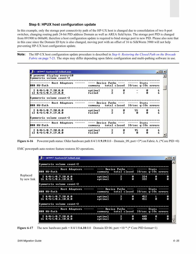
Step 6: HPUX host configuration updateIn this example, only the storage port connectivity path of the HP-UX host is changed due to consolidation of two 8-port switches, changing routing path 24-bit PID address Domain as well as AREA field bytes. The storage port PID is changed from 091900 to 060a00, therefore a host configuration update is required to bind storage port to new PID. Please also note that in this case since the Domain ID byte is also changed, moving port with an offset of 16 to SilkWorm 3900 will not help preventing HP-UX host configuration update.
Note: The HP-UX host configuration update procedure is described in Step 6: Restoring the Closed Path on the Brocade Fabric on page 7-21. The steps may differ depending upon fabric configuration and multi-pathing software in use.
Figure 6-16 Powermt path status: Older hardware path 8/4/1/0.9.19.0.0 – Domain_09, port =3*) on Fabric A. (*Core PID =0)
EMC powerpath auto-restore feature restores IO operations.
Figure 6-17 The new hardware path = 8/4/1/0.6.10.0.0 Domain ID 06; port =10 * (* Core PID format=1)
Replaced by new link
SAN Migration Guide 6 -35

6.4.5.2. Collapsing Storage Port Switch “Domain _06” into “Domain _09”1. In this case when both 8-port switches are consolidated to a single SilkWorm 3900, assuming the switch “Domain_09”,
the affected host platforms will be Windows, AIX and Solaris. Since the storage Domain and Port changes for these hosts, depending on their current persistent binding, they must follow the specified recovery procedure described in Step 6: Restoring the Closed Path on the Brocade Fabric on page 7-21.
Figure 6-18
2. Update the zone configuration for Fabric A to reflect the port ID change. For more information, refer to Port ID Persistent Binding Procedure on page 5-3.
Example: Zoning configuration on storage ports for AIX, Solaris, and Windows on switch “Domain_06” prior to migration.
Domain_06:admin> switchshow (older switch SW-3200)switchName: Domain_06switchType: 16.2switchState: OnlineswitchMode: NativeswitchRole: PrincipalswitchDomain: 6switchId: fffc06switchWwn: 10:00:00:60:69:c0:06:ecswitchBeacon: OFFZoning: ON (Migration_A)port 0: -- N2 No_Moduleport 1: -- N2 No_Moduleport 2: id N2 No_Lightport 3: -- N2 No_Moduleport 4: id N2 No_Lightport 5: id N1 Online F-Port 50:06:04:82:c3:a0:75:bbport 6: id N2 Online F-Port 50:06:04:82:c3:a0:75:b3port 7: id N1 Online F-Port 50:06:04:82:c3:a0:75:8d
Domain_06:admin> cfgShowFabric Zone Configurationcfg: Migration_A zone: Portzone_HPUX_hba01 4,4 9,3 zone: Portzone_Solaris_hba0 3,7 6,7 zone: portzone_AIX22_hba0 4,6 6,6 zone: portzone_w2k_hba0 3,5 6,5
SD
Si lkWorm 2 80 0
1 3 5 7 9 1 1 13 1 5
0 2 4 6 8 1 0 12 1 4
0
0
0
0
1
Domain_ 03
SD
Sil kWorm 21000 2 4 6
1 3 5 7
SD
SD
Si lkWorm 2 80 0
1 3 5 7 9 1 1 13 1 5
0 2 4 6 8 1 0 12 1 4
Domain_ 01
Domain_ 04(SW-2250) (SW-2800)
(SW-2400)
Fabric-A
Domain_ 09(SW-3900)
5
SAN Migration Guide 6 -36
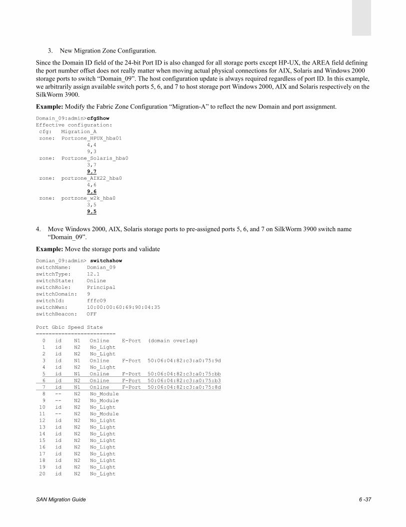
3. New Migration Zone Configuration.
Since the Domain ID field of the 24-bit Port ID is also changed for all storage ports except HP-UX, the AREA field defining the port number offset does not really matter when moving actual physical connections for AIX, Solaris and Windows 2000 storage ports to switch “Domain_09”. The host configuration update is always required regardless of port ID. In this example, we arbitrarily assign available switch ports 5, 6, and 7 to host storage port Windows 2000, AIX and Solaris respectively on the SilkWorm 3900.
Example: Modify the Fabric Zone Configuration “Migration-A” to reflect the new Domain and port assignment.
Domain_09:admin>cfgShowEffective configuration: cfg: Migration_A zone: Portzone_HPUX_hba01 4,4 9,3 zone: Portzone_Solaris_hba0 3,7 9,7 zone: portzone_AIX22_hba0 4,6 9,6 zone: portzone_w2k_hba0 3,5 9,5
4. Move Windows 2000, AIX, Solaris storage ports to pre-assigned ports 5, 6, and 7 on SilkWorm 3900 switch name “Domain_09”.
Example: Move the storage ports and validate
Domian_09:admin> switchshowswitchName: Domian_09switchType: 12.1switchState: OnlineswitchRole: PrincipalswitchDomain: 9switchId: fffc09switchWwn: 10:00:00:60:69:90:04:35switchBeacon: OFF
Port Gbic Speed State========================= 0 id N1 Online E-Port (domain overlap) 1 id N2 No_Light 2 id N2 No_Light 3 id N1 Online F-Port 50:06:04:82:c3:a0:75:9d 4 id N2 No_Light 5 id N1 Online F-Port 50:06:04:82:c3:a0:75:bb 6 id N2 Online F-Port 50:06:04:82:c3:a0:75:b3 7 id N1 Online F-Port 50:06:04:82:c3:a0:75:8d 8 -- N2 No_Module 9 -- N2 No_Module 10 id N2 No_Light 11 -- N2 No_Module 12 id N2 No_Light 13 id N2 No_Light 14 id N2 No_Light 15 id N2 No_Light 16 id N2 No_Light 17 id N2 No_Light 18 id N2 No_Light 19 id N2 No_Light 20 id N2 No_Light
SAN Migration Guide 6 -37

21 id N2 No_Light 22 id N2 No_Light 23 id N2 No_Light 24 -- N2 No_Module 25 -- N2 No_Module 26 -- N2 No_Module 27 -- N2 No_Module 28 -- N2 No_Module 29 id N2 No_Light 30 id N2 No_Light 31 id N2 No_Light
5. Validate the fabric.
Example: Validating the fabric
Domian_09:admin> fabricshowSwitch ID Worldwide Name Enet IP Addr FC IP Addr Name------------------------------------------------------------------------- 1: fffc01 10:00:00:60:69:20:3a:66 192.168.162.55 0.0.0.0 "Domain_01" 3: fffc03 10:00:00:60:69:10:92:b3 192.168.162.59 0.0.0.0 "Domain_03" 4: fffc04 10:00:00:60:69:10:38:3e 192.168.156.126 0.0.0.0 >"Domain_04" 9: fffc09 10:00:00:60:69:90:04:35 192.168.162.58 0.0.0.0 "Domian_09"The Fabric has 4 switches
6. At this point the Symmetrix storage device ports for all hosts must be logged into the new SilkWorm 3900 switch “Domain_09”.
Domian_09:admin> nsallshow8 Nx_Ports in the Fabric { 030500 030700 040400 040600 090300 090500 090600 090700}
Domian_09:admin> nsShowThe Local Name Server has 8 entries { Type Pid COS PortName NodeName TTL(sec)*N 030500; 2,3;10:00:00:00:c9:24:4e:b1;20:00:00:00:c9:21:9c:79; 480 FC4s: FCP Fabric Port Name: 20:05:00:60:69:10:92:b3*N 030700; 2,3;10:00:00:00:c9:2f:20:71;20:00:00:00:c9:2f:20:71; 480 FC4s: FCP Fabric Port Name: 20:07:00:60:69:10:92:b3*N 040400; 3;50:06:0b:00:00:08:fe:34;50:06:0b:00:00:08:fe:35; 480 FC4s: FCP Fabric Port Name: 20:04:00:60:69:10:38:3e*N 040600; 2,3;10:00:00:00:c9:2f:1d:1d;20:00:00:00:c9:2f:1d:1d; 480 Fabric Port Name: 20:06:00:60:69:10:38:3eN 090300; 3;50:06:04:82:c3:a0:75:9d;50:06:04:82:c3:a0:75:9d; na FC4s: FCP [EMC SYMMETRIX 5568] Fabric Port Name: 20:03:00:60:69:90:04:35N 090500; 3;50:06:04:82:c3:a0:75:bb;50:06:04:82:c3:a0:75:bb; na FC4s: FCP [EMC SYMMETRIX 5568] Fabric Port Name: 20:05:00:60:69:90:04:35N 090600; 3;50:06:04:82:c3:a0:75:b3;50:06:04:82:c3:a0:75:b3; na FC4s: FCP [EMC SYMMETRIX 5568] Fabric Port Name: 20:06:00:60:69:90:04:35N 090700; 3;50:06:04:82:c3:a0:75:8d;50:06:04:82:c3:a0:75:8d; na FC4s: FCP [EMC SYMMETRIX 5568] Fabric Port Name: 20:07:00:60:69:90:04:35
7. When trying to restore closed paths of Fabric A from EMC Powerpath on AIX, Solaris and Windows 2000, the paths on Solaris and AIX remain closed.
SAN Migration Guide 6 -38

8. Restoring paths on AIX, Windows, and Solaris.
• HP-UX: HP-UX path has not been affected on Fabric A, it remains open all the time.(To restore path on HP-UX, please refer to Step 6: Restoring the Closed Path on the Brocade Fabric on page 7-21.)
• AIX: Host configuration update is required (See Step 6: Restoring the Closed Path on the Brocade Fabric on page 7-21.)
• Solaris: Host configuration update is required (See step 10.)
• Windows 2000: Powerpath restores path on Windows 2000, may require disk scan if not auto restored.
9. Solaris host configuration update. This procedure is applicable to the Port ID binding method on the Solaris host.
Warning: After updating the host configuration file, a host reboot is required for the change to be effective. A system reboot will completely cease IOs for the duration of boot time. Thus, it is a disruptive procedure even in a redundant fabric environment and must be proceeded with caution. Before re-booting the host, all IO operations must be stopped on the open path of Fabric B. File systems on Symmetrix volumes must be unmounted.
Example: Scan Storage Devices
# drvconfig;devlinks;disks (Run to scan the storage devices)# format (Run format command to scan the storage devices)Searching for disks...donec2t1d0: configured with capacity of 6.56MBAVAILABLE DISK SELECTIONS: 0. c0t0d0 <SUN18G cyl 7506 alt 2 hd 19 sec 248> /pci@1f,4000/scsi@3/sd@0,0 1. c0t1d0 <SUN36G cyl 24620 alt 2 hd 27 sec 107> /pci@1f,4000/scsi@3/sd@1,0 2. c2t1d0 <EMC-SYMMETRIX-5568 cyl 14 alt 2 hd 15 sec 64> /pci@1f,4000/lpfc@4/sd@1,0 3. c2t1d1 <EMC-SYMMETRIX-5567 cyl 9158 alt 2 hd 15 sec 64> SYMlun01 /pci@1f,4000/lpfc@4/sd@1,1 4. c2t1d2 <EMC-SYMMETRIX-5567 cyl 9158 alt 2 hd 15 sec 64> SYMlun02 /pci@1f,4000/lpfc@4/sd@1,2 5. c3t2d0 <drive not available: formatting> /pci@1f,2000/lpfc@1/sd@2,0 6. c3t2d1 <EMC-SYMMETRIX-5567 cyl 9158 alt 2 hd 15 sec 64> SYMlun01 /pci@1f,2000/lpfc@1/sd@2,1 7. c3t2d2 <EMC-SYMMETRIX-5567 cyl 9158 alt 2 hd 15 sec 64> SYMlun02 /pci@1f,2000/lpfc@1/sd@2,2 8. emcpower1a <EMC-SYMMETRIX-5567 cyl 9158 alt 2 hd 15 sec 64> SYMlun01 /pseudo/emcp@1 9. emcpower2a <EMC-SYMMETRIX-5567 cyl 9158 alt 2 hd 15 sec 64> SYMlun02 /pseudo/emcp@2
Example: EMC Powerpath Storage port =14aa is closed because of change in Port ID
# powermt display dev=allPseudo name=emcpower1aSymmetrix frame ID=000185500118; volume ID=001state=alive; policy=SymmOpt; priority=0; queued-IOs=0=========================================================================------------- Host Devices ------------ - Symm - --- Path ---- -- Stats ---### HW-path device director mode state q-IOs errors============================================================================== 1 pci@1f,4000/lpfc@4 c2t1d1s0 FA 3bB active open 0 0 0 pci@1f,2000/lpfc@1 c3t2d1s0 FA 14aA active closed 0 6
Pseudo name=emcpower2aSymmetrix frame ID=000185500118; volume ID=002state=alive; policy=SymmOpt; priority=0; queued-IOs=0
SAN Migration Guide 6 -39
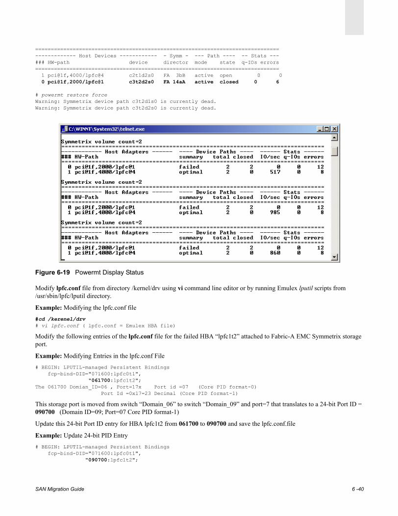
==============================================================================------------- Host Devices ------------ - Symm - --- Path ---- -- Stats ---### HW-path device director mode state q-IOs errors============================================================================== 1 pci@1f,4000/lpfc@4 c2t1d2s0 FA 3bB active open 0 0 0 pci@1f,2000/lpfc@1 c3t2d2s0 FA 14aA active closed 0 6
# powermt restore forceWarning: Symmetrix device path c3t2d1s0 is currently dead.Warning: Symmetrix device path c3t2d2s0 is currently dead.
Figure 6-19 Powermt Display Status
Modify lpfc.conf file from directory /kernel/drv using vi command line editor or by running Emulex lputil scripts from /usr/sbin/lpfc/lputil directory.
Example: Modifying the lpfc.conf file
#cd /kerenel/drv# vi lpfc.conf ( lpfc.conf = Emulex HBA file)
Modify the following entries of the lpfc.conf file for the failed HBA “lpfc1t2” attached to Fabric-A EMC Symmetrix storage port.
Example: Modifying Entries in the lpfc.conf File
# BEGIN: LPUTIL-managed Persistent Bindings fcp-bind-DID="071600:lpfc0t1", "061700:lpfc1t2";The 061700 Domian_ID=06 , Port=17x Port id =07 (Core PID format-0)
Port Id =0x17=23 Decimal (Core PID format-1)
This storage port is moved from switch “Domain_06” to switch “Domain_09” and port=7 that translates to a 24-bit Port ID = 090700 (Domain ID=09; Port=07 Core PID format-1)
Update this 24-bit Port ID entry for HBA lpfc1t2 from 061700 to 090700 and save the lpfc.conf.file
Example: Update 24-bit PID Entry
# BEGIN: LPUTIL-managed Persistent Bindings fcp-bind-DID="071600:lpfc0t1", "090700:lpfc1t2";
SAN Migration Guide 6 -40
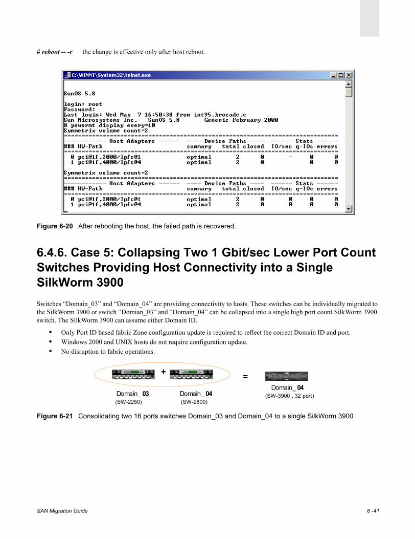
# reboot -- -r the change is effective only after host reboot.
Figure 6-20 After rebooting the host, the failed path is recovered.
6.4.6. Case 5: Collapsing Two 1 Gbit/sec Lower Port Count Switches Providing Host Connectivity into a Single SilkWorm 3900Switches “Domain_03” and “Domain_04” are providing connectivity to hosts. These switches can be individually migrated to the SilkWorm 3900 or switch “Domian_03” and “Domain_04” can be collapsed into a single high port count SilkWorm 3900 switch. The SilkWorm 3900 can assume either Domain ID.
• Only Port ID based fabric Zone configuration update is required to reflect the correct Domain ID and port.• Windows 2000 and UNIX hosts do not require configuration update.• No disruption to fabric operations.
Figure 6-21 Consolidating two 16 ports switches Domain_03 and Domain_04 to a single SilkWorm 3900
Domain_ 04(SW-3900 , 32 port)
SD
Silk Wo rm 28 00
1 3 5 7 9 11 13 1 5
0 2 4 6 8 10 12 1 4
Domain_ 03
SD
Si lkWorm 2 80 0
1 3 5 7 9 1 1 13 1 5
0 2 4 6 8 1 0 12 1 4
Domain_ 04(SW-2250) (SW-2800)
=+
SAN Migration Guide 6 -41
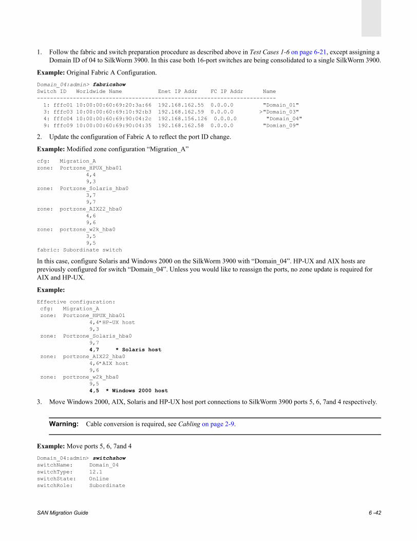
1. Follow the fabric and switch preparation procedure as described above in Test Cases 1-6 on page 6-21, except assigning a Domain ID of 04 to SilkWorm 3900. In this case both 16-port switches are being consolidated to a single SilkWorm 3900.
Example: Original Fabric A Configuration.
Domain_04:admin> fabricshowSwitch ID Worldwide Name Enet IP Addr FC IP Addr Name------------------------------------------------------------------------- 1: fffc01 10:00:00:60:69:20:3a:66 192.168.162.55 0.0.0.0 "Domain_01" 3: fffc03 10:00:00:60:69:10:92:b3 192.168.162.59 0.0.0.0 >"Domain_03" 4: fffc04 10:00:00:60:69:90:04:2c 192.168.156.126 0.0.0.0 "Domain_04" 9: fffc09 10:00:00:60:69:90:04:35 192.168.162.58 0.0.0.0 "Domian_09"
2. Update the configuration of Fabric A to reflect the port ID change.
Example: Modified zone configuration “Migration_A”
cfg: Migration_Azone: Portzone_HPUX_hba01 4,4 9,3zone: Portzone_Solaris_hba0 3,7 9,7zone: portzone_AIX22_hba0 4,6 9,6zone: portzone_w2k_hba0 3,5 9,5fabric: Subordinate switch
In this case, configure Solaris and Windows 2000 on the SilkWorm 3900 with “Domain_04”. HP-UX and AIX hosts are previously configured for switch “Domain_04”. Unless you would like to reassign the ports, no zone update is required for AIX and HP-UX.
Example:
Effective configuration: cfg: Migration_A zone: Portzone_HPUX_hba01 4,4*HP-UX host 9,3 zone: Portzone_Solaris_hba0 9,7 4,7 * Solaris host zone: portzone_AIX22_hba0 4,6*AIX host 9,6 zone: portzone_w2k_hba0 9,5 4,5 * Windows 2000 host
3. Move Windows 2000, AIX, Solaris and HP-UX host port connections to SilkWorm 3900 ports 5, 6, 7and 4 respectively.
Warning: Cable conversion is required, see Cabling on page 2-9.
Example: Move ports 5, 6, 7and 4
Domain_04:admin> switchshowswitchName: Domain_04switchType: 12.1switchState: OnlineswitchRole: Subordinate
SAN Migration Guide 6 -42
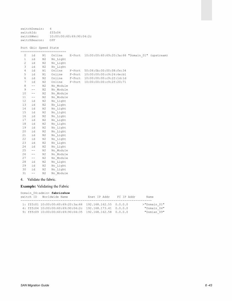
switchDomain: 4switchId: fffc04switchWwn: 10:00:00:60:69:90:04:2cswitchBeacon: OFF
Port Gbic Speed State========================= 0 id N1 Online E-Port 10:00:00:60:69:20:3a:66 "Domain_01" (upstream) 1 id N2 No_Light 2 id N2 No_Light 3 id N2 No_Light 4 id N1 Online F-Port 50:06:0b:00:00:08:fe:34 5 id N1 Online F-Port 10:00:00:00:c9:24:4e:b1 6 id N2 Online F-Port 10:00:00:00:c9:2f:1d:1d 7 id N2 Online F-Port 10:00:00:00:c9:2f:20:71 8 -- N2 No_Module 9 -- N2 No_Module 10 -- N2 No_Module 11 -- N2 No_Module 12 id N2 No_Light 13 id N2 No_Light 14 id N2 No_Light 15 id N2 No_Light 16 id N2 No_Light 17 id N2 No_Light 18 id N2 No_Light 19 id N2 No_Light 20 id N2 No_Light 21 id N2 No_Light 22 id N2 No_Light 23 id N2 No_Light 24 id N2 No_Light 25 -- N2 No_Module 26 -- N2 No_Module 27 -- N2 No_Module 28 id N2 No_Light 29 id N2 No_Light 30 id N2 No_Light 31 -- N2 No_Module
4. Validate the fabric.
Example: Validating the Fabric
Domain_04:admin> fabricshowswitch ID Worldwide Name Enet IP Addr FC IP Addr Name------------------------------------------------------------------------ 1: fffc01 10:00:00:60:69:20:3a:66 192.168.162.55 0.0.0.0 >"Domain_01" 4: fffc04 10:00:00:60:69:90:04:2c 192.168.173.41 0.0.0.0 "Domain_04" 9: fffc09 10:00:00:60:69:90:04:35 192.168.162.58 0.0.0.0 "Domian_09"
SAN Migration Guide 6 -43

Figure 6-22 Resulting Fabric A
5. Resume IO operations on all hosts on Fabric A via SilkWorm 3900 switch “Domain_04”.
ConclusionThe Domain ID or port ID change on SilkWorm fabric switches providing host connectivity requires only port based zone configuration change. A World Wide Port Name based fabric zone configuration does not require any update.
6.4.7. Case 6: Replacing a Lower Port Count Core Switch with High Performance SilkWorm 12000
In previous cases, we have successfully upgraded the fabric edge switches providing storage and host connectivity to higher port count 2 Gbit/sec SilkWorm 3900. The Core switch of redundant Fabric A is still a SilkWorm 2400 switch. In the previous example of Fabric B, the Core switch is upgraded to SilkWorm 3900. This case demonstrates the ease of upgrading the Core switch with high port count Brocade director class SilkWorm 12000. This will complete the 2 Gbit Migration of Fabric A recommended Core /Edge topology for large fabrics with SilkWorm 12000 as a Core and SilkWorm 3900 as edge switches.
0
4
0
6
1SD
Sil kWorm 21000 2 4 6
1 3 5 7
SDDomain_ 01
Domain_ 09
(SW-2400)
(SW-3900)
Domain_ 04(SW-3900 , 32 port)
Fabric-A
0
4
0
6
1SD
Sil kWorm 21000 2 4 6
1 3 5 7
SD
Domain_ 01
Domain_ 09
(SW-2400)
(SW-3900)
Domain_ 04(SW-3900 , 32 port)
Fabric-A
CP0
cp1
SW-12000 , 64 port
Replacing Core w ith SilkWorm-12000
SAN Migration Guide 6 -44
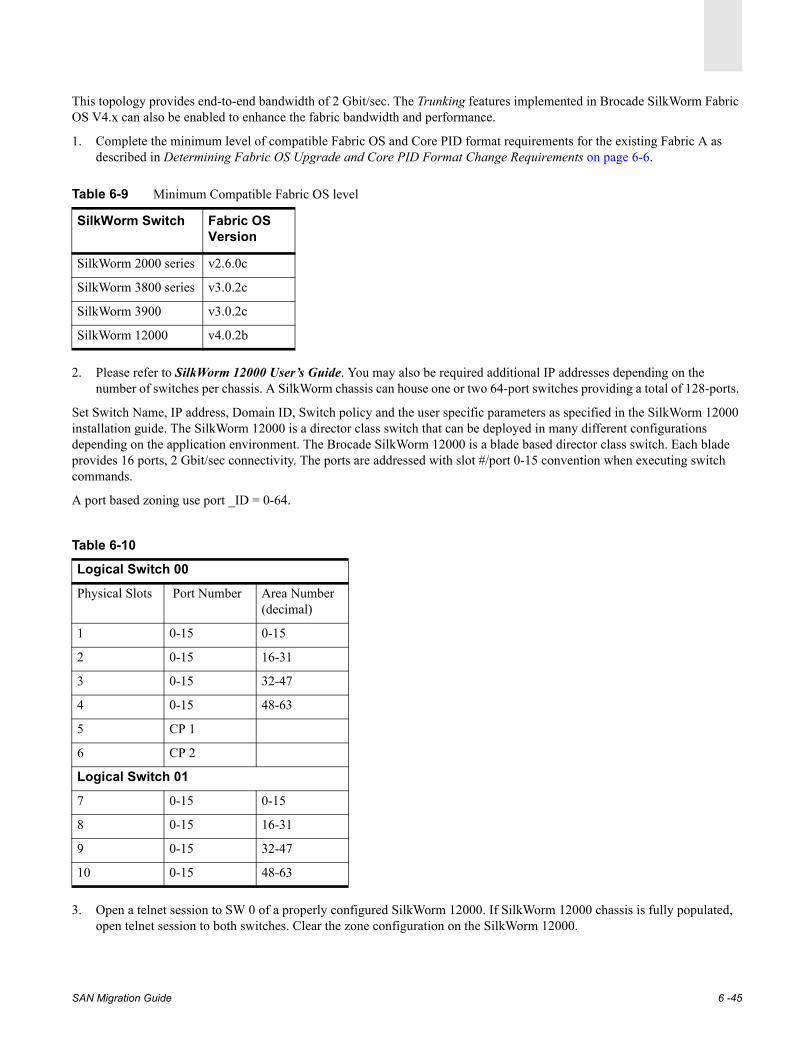
This topology provides end-to-end bandwidth of 2 Gbit/sec. The Trunking features implemented in Brocade SilkWorm Fabric OS V4.x can also be enabled to enhance the fabric bandwidth and performance.
1. Complete the minimum level of compatible Fabric OS and Core PID format requirements for the existing Fabric A as described in Determining Fabric OS Upgrade and Core PID Format Change Requirements on page 6-6.
2. Please refer to SilkWorm 12000 User’s Guide. You may also be required additional IP addresses depending on the number of switches per chassis. A SilkWorm chassis can house one or two 64-port switches providing a total of 128-ports.
Set Switch Name, IP address, Domain ID, Switch policy and the user specific parameters as specified in the SilkWorm 12000 installation guide. The SilkWorm 12000 is a director class switch that can be deployed in many different configurations depending on the application environment. The Brocade SilkWorm 12000 is a blade based director class switch. Each blade provides 16 ports, 2 Gbit/sec connectivity. The ports are addressed with slot #/port 0-15 convention when executing switch commands.
A port based zoning use port _ID = 0-64.
3. Open a telnet session to SW 0 of a properly configured SilkWorm 12000. If SilkWorm 12000 chassis is fully populated, open telnet session to both switches. Clear the zone configuration on the SilkWorm 12000.
Table 6-9 Minimum Compatible Fabric OS level
SilkWorm Switch Fabric OS Version
SilkWorm 2000 series v2.6.0c
SilkWorm 3800 series v3.0.2c
SilkWorm 3900 v3.0.2c
SilkWorm 12000 v4.0.2b
Table 6-10
Logical Switch 00
Physical Slots Port Number Area Number (decimal)
1 0-15 0-15
2 0-15 16-31
3 0-15 32-47
4 0-15 48-63
5 CP 1
6 CP 2
Logical Switch 01
7 0-15 0-15
8 0-15 16-31
9 0-15 32-47
10 0-15 48-63
SAN Migration Guide 6 -45
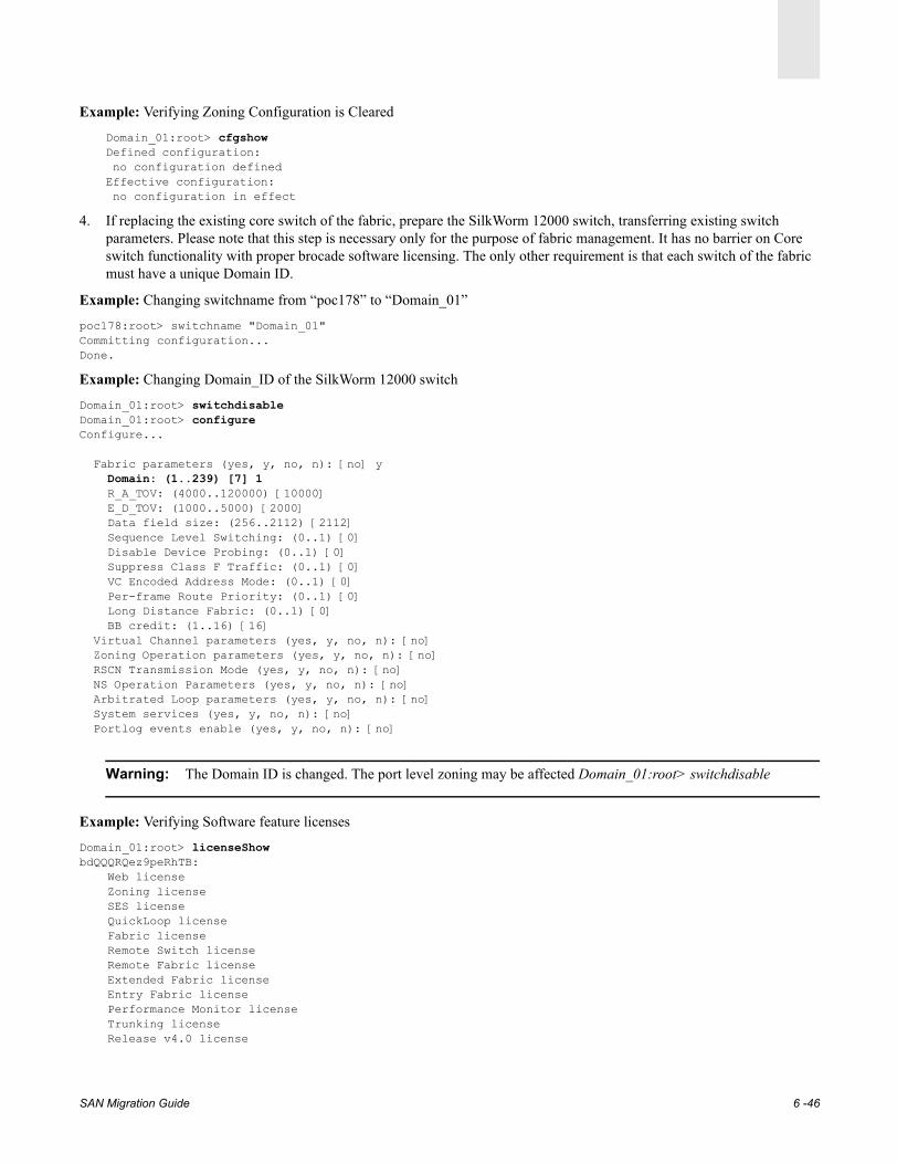
Example: Verifying Zoning Configuration is Cleared
Domain_01:root> cfgshowDefined configuration: no configuration definedEffective configuration: no configuration in effect
4. If replacing the existing core switch of the fabric, prepare the SilkWorm 12000 switch, transferring existing switch parameters. Please note that this step is necessary only for the purpose of fabric management. It has no barrier on Core switch functionality with proper brocade software licensing. The only other requirement is that each switch of the fabric must have a unique Domain ID.
Example: Changing switchname from “poc178” to “Domain_01”
poc178:root> switchname "Domain_01"Committing configuration...Done.
Example: Changing Domain_ID of the SilkWorm 12000 switch
Domain_01:root> switchdisableDomain_01:root> configureConfigure...
Fabric parameters (yes, y, no, n): [no] y Domain: (1..239) [7] 1 R_A_TOV: (4000..120000) [10000] E_D_TOV: (1000..5000) [2000] Data field size: (256..2112) [2112] Sequence Level Switching: (0..1) [0] Disable Device Probing: (0..1) [0] Suppress Class F Traffic: (0..1) [0] VC Encoded Address Mode: (0..1) [0] Per-frame Route Priority: (0..1) [0] Long Distance Fabric: (0..1) [0] BB credit: (1..16) [16] Virtual Channel parameters (yes, y, no, n): [no] Zoning Operation parameters (yes, y, no, n): [no] RSCN Transmission Mode (yes, y, no, n): [no] NS Operation Parameters (yes, y, no, n): [no] Arbitrated Loop parameters (yes, y, no, n): [no] System services (yes, y, no, n): [no] Portlog events enable (yes, y, no, n): [no]
Warning: The Domain ID is changed. The port level zoning may be affected Domain_01:root> switchdisable
Example: Verifying Software feature licenses
Domain_01:root> licenseShowbdQQQRQez9peRhTB: Web license Zoning license SES license QuickLoop license Fabric license Remote Switch license Remote Fabric license Extended Fabric license Entry Fabric license Performance Monitor license Trunking license Release v4.0 license
SAN Migration Guide 6 -46
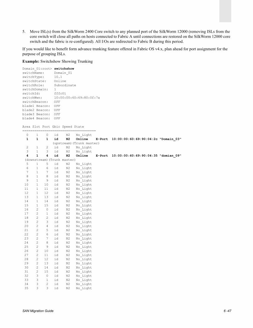
5. Move ISL(s) from the SilkWorm 2400 Core switch to any planned port of the SilkWorm 12000 (removing ISLs from the core switch will close all paths on hosts connected to Fabric A until connections are restored on the SilkWorm 12000 core switch and the fabric is re-configured). All I/Os are redirected to Fabric B during this period.
If you would like to benefit form advance trunking feature offered in Fabric OS v4.x, plan ahead for port assignment for the purpose of grouping ISLs.
Example: Switchshow Showing Trunking
Domain_01:root> switchshowswitchName: Domain_01switchType: 10.1switchState: OnlineswitchRole: SubordinateswitchDomain: 1switchId: fffc01switchWwn: 10:00:00:60:69:80:0f:7aswitchBeacon: OFFblade1 Beacon: OFFblade2 Beacon: OFFblade3 Beacon: OFFblade4 Beacon: OFF
Area Slot Port Gbic Speed State===================================== 0 1 0 id N2 No_Light 1 1 1 id N2 Online E-Port 10:00:00:60:69:90:04:2c "Domain_03" (upstream)(Trunk master) 2 1 2 id N2 No_Light 3 1 3 id N2 No_Light 4 1 4 id N2 Online E-Port 10:00:00:60:69:90:04:35 "domian_09" (downstream)(Trunk master) 5 1 5 id N2 No_Light 6 1 6 id N2 No_Light 7 1 7 id N2 No_Light 8 1 8 id N2 No_Light 9 1 9 id N2 No_Light 10 1 10 id N2 No_Light 11 1 11 id N2 No_Light 12 1 12 id N2 No_Light 13 1 13 id N2 No_Light 14 1 14 id N2 No_Light 15 1 15 id N2 No_Light 16 2 0 id N2 No_Light 17 2 1 id N2 No_Light 18 2 2 id N2 No_Light 19 2 3 id N2 No_Light 20 2 4 id N2 No_Light 21 2 5 id N2 No_Light 22 2 6 id N2 No_Light 23 2 7 id N2 No_Light 24 2 8 id N2 No_Light 25 2 9 id N2 No_Light 26 2 10 id N2 No_Light 27 2 11 id N2 No_Light 28 2 12 id N2 No_Light 29 2 13 id N2 No_Light 30 2 14 id N2 No_Light 31 2 15 id N2 No_Light 32 3 0 id N2 No_Light 33 3 1 id N2 No_Light 34 3 2 id N2 No_Light 35 3 3 id N2 No_Light
SAN Migration Guide 6 -47

6. Verify the fabric and observe ISL traffic.
Example: Fabricshow and portperfshow Showing ISL Traffic
Domain_01:root> fabricshowSwitch ID Worldwide Name Enet IP Addr FC IP Addr Name------------------------------------------------------------------------- 1: fffc01 10:00:00:60:69:80:0f:7a 192.168.173.178 0.0.0.0 "Domain_01" 3: fffc03 10:00:00:60:69:90:04:2c 192.168.173.41 0.0.0.0 >"Domain_03" 9: fffc09 10:00:00:60:69:90:04:35 192.168.162.58 0.0.0.0 "Domian_09"
The Fabric has 3 switchesDomain_01:root> portperfshow
0 1 2 3 4 5 6 7 8 9 10 11 12 13 14 15=======================================================slot 1: 0 10m 0 0 10m 0 0 0 0 0 0 0 0 0 0 0
7. Brocade Fabric OS v4.x offers the Advanced Trunking feature which can be enabled with proper licensing on SilkWorm 3800, 3900, and 12000 switches. The trunking group is defined by “quads”. Create ISL trunks at this, time if planned.
For instance on a 16-port switch or SilkWorm 12000 blade, quads are defined as ports 0-3, 4-7, 8-11and 12-15.
Trunking commandsswitchCfgTrunk Configure all ports on the switch for trunkingportCfgTrunkPort Configure a port for trunking
Example: Trunking example: Adding a second ISL to group 0 and 1 and enabling the Trunking feature.
Slot 1 /Port 1 ISL goes to switch Doamin_03, port 1 of SilkWorm 3900
Slot1 /Port 4 ISL goes to switch Doamin_09 port 1 of SilkWorm 3900
Example: Adding ISL(s) on SilkWorm ports as follows:
Slot 1 / Port 1 ISL goes to Doamin_03 port =1 of SilkWorm 3900
Slot 1 /Port 2 ISL goes to Doamin_03 port=2 of SilkWorm 3900 Trunk grp-0
Slot1 / Port 4 ISL goes to switch Doamin_09 =1 of SilkWorm 3900
Slot1 /Port 5 ISL goes to switch Doamin_09=2 of SilkWorm 3900 Trunk grp-1
SAN Migration Guide 6 -48

Example: Switchshow showing Trunk Groups
The example below shows IO Operations distributed across trunk ports after Migration.
Example: portperfshow Showing Trunking Performance
Domain_01:root> portperfshow0 1 2 3 4 5 6 7 8 9 10 11 12 13 14 15
===================================================slot 1: 0 5.5m 5.1m 0 5.8m 4.3m 0 0 0 0 0 0 0 0 0 0
Domain_01:root> switchshowswitchName: domain_01switchType: 10.1switchState: OnlineswitchRole: SubordinateswitchDomain: 1switchId: fffc01switchWwn: 10:00:00:60:69:80:0f:7aswitchBeacon: OFFblade1 Beacon: OFFblade2 Beacon: OFFblade3 Beacon: OFFblade4 Beacon: OFF
Area Slot Port Gbic Speed State===================================== 0 1 0 id N2 No_Light 1 1 1 id N2 Online E-Port 10:00:00:60:69:90:04:2c "Domain_03" (upstream)(Trunk master) 2 1 2 id N2 Online E-Port (Trunk port, master is Slot 1 Port1) 3 1 3 id N2 No_Light 4 1 4 id N2 Online E-Port 10:00:00:60:69:90:04:35 "domian_09" (downstream)(Trunk master) 5 1 5 id N2 Online E-Port (Trunk port, master is Slot 1 Port 4) 6 1 6 id N2 No_Light 7 1 7 id N2 No_Light 8 1 8 id N2 No_Light
9 1 9 id N2 No_Light
SAN Migration Guide 6 -49
SAN Migration Guide
Chapter
7
Migration Procedure from McData to Brocade Fabric7.1. Migration from McData to Brocade FabricThis procedure outlines the necessary steps of migrating from an existing McData fabric to a Brocade fabric. A single non-resilient fabric migration is only possible by bringing the fabric offline. However with preparations the downtime can be minimized. On the other hand, a redundant fabric topology make online migration possible by taking one fabric offline and upgrading it while the second fabric remains open for IO transactions. Figure 7-1 on page 7-2 illustrates an existing McData Fabric topology. Fabric A is consists of McData director ED-6064 and switch models ES-3016 (16 port, 1Gbit/sec). Fabric B provides an alternate IO transaction path during the migration process.
For the purpose of this illustration, an identical Brocade Fabric A is constructed, replacing ES-3016 and ED-6064 with Brocade high port count and high performance 2 Gbit/sec SilkWorm 3900 and SilkWorm 12000 switches respectively.
In order for a host to access storage, the host adapter driver for the Fibre Channel controller must be installed and configuration file must be set up specifying storage links. For the purpose of this illustration UNIX and Windows based servers were configured to access EMC Symmetrix storage using multi-pathing software (Powerpath) from EMC. For host setup detail please refer to Appendix A, Operating System Platforms platforms.
Topology Redundant Fabric A and B, core/edge Configuration.
McData Fabric A• ES-3016 Edge switch providing host connectivity firmware version 05.01.00.17• ED-6064 switch providing storage connectivity firmware version 05.01.00.17• Management tool: Web based SANpilot, Telnet CLI
Brocade Fabric A• SilkWorm 3900 Edge switch - Fabric OS version 4.0.2c or later• SilkWorm 12000 Core switch - Fabric OS version 4.0.2c or later• Management tool - Brocade Web Tools, Telnet, Brocade “Zone_convert.exe” utility*
7-1

Migration Procedure from McData to Brocade Fabric7
Figure 7-1 Diagram of Migration from McData switches to Brocade SilkWorm switches
7.2. The Basic Steps for Migration from McData to BrocadeIdeally, an online migration process in a redundant fabric topology environment should be transparent to attached devices. There are some variables at host, fabric and storage level that can significantly influence the migration process if over looked. The key to a successful migration is to identify and understand these variables well in advance and develop a step by step process to address them. Steps 1 through 6 described below simplify the entire migration process.
Step 1: Assessing System and Storage Configuration on page 7-3
Step 2: Assessing McData Fabric Operating Parameters on page 7-4
Step 3: Setup and Configuration of the Brocade Fabric on page 7-9
Step 4: Import McData Zoning to the Brocade Fabric on page 7-12
Step 5: Moving Devices to the Brocade Fabric on page 7-17
Step 6: Restoring the Closed Path on the Brocade Fabric on page 7-21
SilkWorm12000
CP0
SilkWorm3900
W2k HP-UXAIX
12bb 5aa 14aa 3bb 14ba 3ab4bb 13aa
AIXW2k Solaris HP-UX
Solaris
McData6064
McData Fabric
McData3016
BAA
BCP0
Symmetrix Storage
Brocade Fabric
7-2 SAN Migration Guide

Migration Procedure from McData to Brocade Fabric 7
7.2.1. Step 1: Assessing System and Storage ConfigurationAs shown in Figure 7-1, Fabric A consists of a ED-6064 director at the core providing access to EMC Symmetrix storage ports and an ES-3016 switch at the edge, connecting hosts. The alternate path from each host to storage is made available via Fabric B in a highly availability environment. The objective is to replace McData Fabric A with Brocade Fabric A which is consists of a Brocade High performance 2 Gbit/sec SilkWorm 12000 at the core and the SilkWorm 3900 at the edge, providing host port connectivity. For more information about assessment, refer to Chapter 2, Assessing the Target SAN.
For Windows and UNIX host and storage configuration, refer to Operating System Platforms on page A-1. The following screens show Windows 2000, Solaris, AIX, and HP-UX systems accessing storage via McData Fabric A and B using EMC Powerpath multipathing software, configured for Symmetrix Optimization (SO) mode, allowing storage access via both active path.
Figure 7-2 Windows 2000 host fabric port A and B IO processing status
Figure 7-3 Solaris host fabric port A and B I/O processing status
SAN Migration Guide 7-3

Migration Procedure from McData to Brocade Fabric7
Figure 7-4 AIX host fabric port A and B I/O processing status
Figure 7-5 HPUX host fabric port A and B I/O processing status
7.2.2. Step 2: Assessing McData Fabric Operating ParametersMcData switch configuration parameters can be accessed either via Telnet CLI or the web based SANpilot Management tool available on the McData switch. To start a SANpilot session, open an Internet Explorer browser and enter the switch IP address. A telnet session can also be established by providing the switch IP address on a command line interface.
The following SANpilot screens are helpful to assess the existing McData fabric configuration as well as switch operating parameters. In most cases, the default operating parameters on Brocade switch are compatible, however the reference parameters obtained from the McData switch can be very helpful in setting up user configurable parameters such as SNMP, that may need to be set. (see Figure 7-7).
7-4 SAN Migration Guide
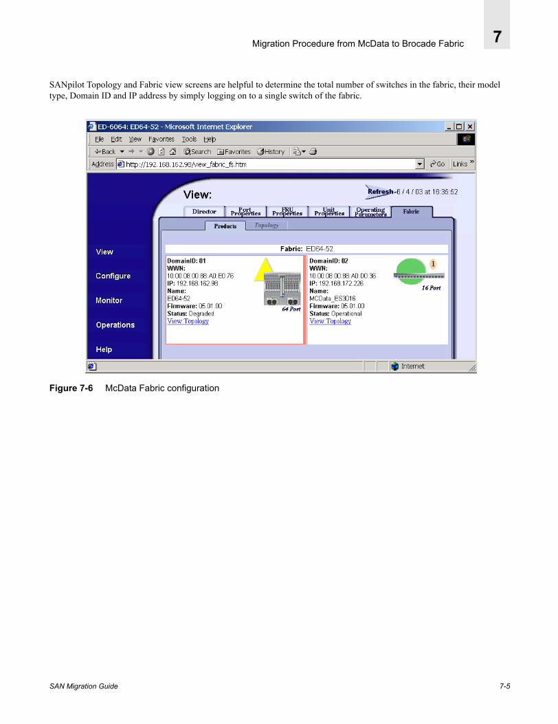
Migration Procedure from McData to Brocade Fabric 7
SANpilot Topology and Fabric view screens are helpful to determine the total number of switches in the fabric, their model type, Domain ID and IP address by simply logging on to a single switch of the fabric.
Figure 7-6 McData Fabric configuration
SAN Migration Guide 7-5

Migration Procedure from McData to Brocade Fabric7
The Operating Parameter tab shows the current configuration setting of the Mcdata switch parameters. This information is crucial to set up Brocade SilkWorm switch operating parameters identical or very close to displacing McData switch.
Figure 7-7 McData Switch Operating parameters (Telnet command: > config switch Show)
7-6 SAN Migration Guide

Migration Procedure from McData to Brocade Fabric 7
The Port Status Monitoring tab shows the device connectivity map, the current status and configuration of the fabric port. The following screen shows ED-6064 is providing connectivity to Symmetrix storage on specific ports for the listed number of hosts. This information is important if hardware zoning and persistent binding is enforced.
Figure 7-8 Port online status and configuration type - (ED-6064 storage ports)
SAN Migration Guide 7-7
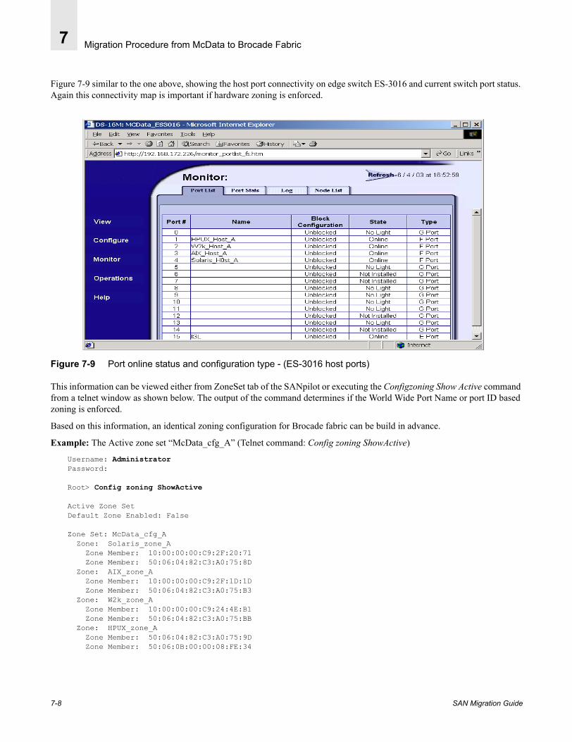
Migration Procedure from McData to Brocade Fabric7
Figure 7-9 similar to the one above, showing the host port connectivity on edge switch ES-3016 and current switch port status. Again this connectivity map is important if hardware zoning is enforced.
Figure 7-9 Port online status and configuration type - (ES-3016 host ports)
This information can be viewed either from ZoneSet tab of the SANpilot or executing the Configzoning Show Active command from a telnet window as shown below. The output of the command determines if the World Wide Port Name or port ID based zoning is enforced.
Based on this information, an identical zoning configuration for Brocade fabric can be build in advance.
Example: The Active zone set “McData_cfg_A” (Telnet command: Config zoning ShowActive)
Username: AdministratorPassword:
Root> Config zoning ShowActive
Active Zone SetDefault Zone Enabled: False
Zone Set: McData_cfg_A Zone: Solaris_zone_A Zone Member: 10:00:00:00:C9:2F:20:71 Zone Member: 50:06:04:82:C3:A0:75:8D Zone: AIX_zone_A Zone Member: 10:00:00:00:C9:2F:1D:1D Zone Member: 50:06:04:82:C3:A0:75:B3 Zone: W2k_zone_A Zone Member: 10:00:00:00:C9:24:4E:B1 Zone Member: 50:06:04:82:C3:A0:75:BB Zone: HPUX_zone_A Zone Member: 50:06:04:82:C3:A0:75:9D Zone Member: 50:06:0B:00:00:08:FE:34
7-8 SAN Migration Guide
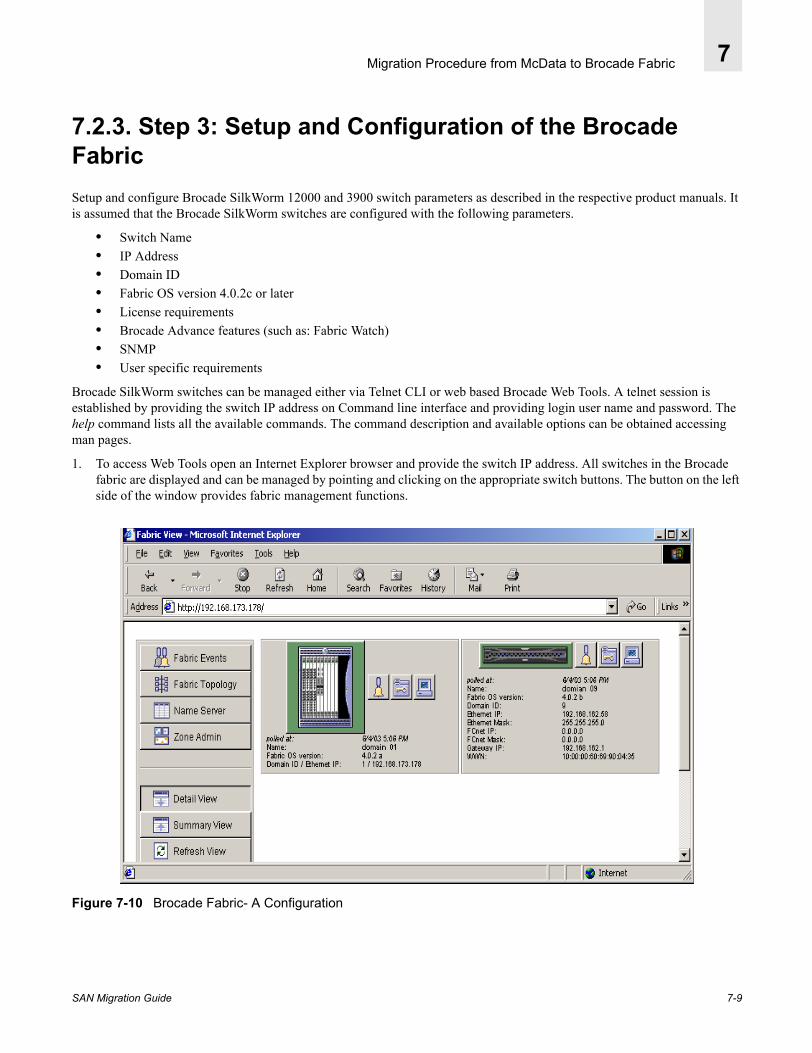
Migration Procedure from McData to Brocade Fabric 7
7.2.3. Step 3: Setup and Configuration of the Brocade FabricSetup and configure Brocade SilkWorm 12000 and 3900 switch parameters as described in the respective product manuals. It is assumed that the Brocade SilkWorm switches are configured with the following parameters.
• Switch Name• IP Address• Domain ID • Fabric OS version 4.0.2c or later• License requirements• Brocade Advance features (such as: Fabric Watch) • SNMP • User specific requirements
Brocade SilkWorm switches can be managed either via Telnet CLI or web based Brocade Web Tools. A telnet session is established by providing the switch IP address on Command line interface and providing login user name and password. The help command lists all the available commands. The command description and available options can be obtained accessing man pages.
1. To access Web Tools open an Internet Explorer browser and provide the switch IP address. All switches in the Brocade fabric are displayed and can be managed by pointing and clicking on the appropriate switch buttons. The button on the left side of the window provides fabric management functions.
Figure 7-10 Brocade Fabric- A Configuration
SAN Migration Guide 7-9

Migration Procedure from McData to Brocade Fabric7
2. Click on Admin view next to the switch icon (middle button). Switch parameters can be verified or setup from the appropriate tab.
Figure 7-11 Switch Admin view
7-10 SAN Migration Guide

Migration Procedure from McData to Brocade Fabric 7
Here is an example of obtaining Brocade fabric topology information showing fabric is consists of two switches named “domain_01” and “domain_09” with Domain ID 1 and 9 respectively.
Figure 7-12 Web Tools - Fabric Topology
Below is an example of obtaining configuration details using the telnet Command Line Interface.
Example: Fabricshow Output
domain_01:root> fabricshow (Telnet CLI)
Switch ID Worldwide Name Enet IP Addr FC IP Addr Name------------------------------------------------------------------------- 1: fffc01 10:00:00:60:69:80:0f:7a 192.168.173.178 0.0.0.0 >"domain_01" SilkWorm 12000 9: fffc09 10:00:00:60:69:90:04:35 192.168.162.58 0.0.0.0 "domian_09" SilkWorm 3900
The Fabric has 2 switches
SAN Migration Guide 7-11

Migration Procedure from McData to Brocade Fabric7
7.2.4. Step 4: Import McData Zoning to the Brocade FabricMcData zoning information can be imported to the Brocade fabric using the zone_convert.exe utility provided by Brocade. Go to www.Brocade.com and click on Brocade Connect.
1. From the Brocade Connect web site, download the file: mcdata-zone_convert.zip.Figure 7-13 shows the executable and supporting dll files. The utility will not function if any of these files are missing.
Figure 7-13 mcdata-zone_convert.zip
2. Unzip the utility file and make sure the required .dll files are present.3. Obtain the IP Address, user login, and password for both McData and Brocade switches. 4. Run the zone_convert.exe and enter the required information (IP Address, User name, and password).
Accessing an Active Zone Set from McDataExample: McData to Brocade Zoning Migration Utility v. 1.0
Enter info for the McData switch to export zoning data.Hostname: 192.168.162.98 Username [Administrator]:Password [password]:
Logging into 192.168.162.98... done.Getting zoning data... done.Zoning table from McData switch 192.168.162.98:
W2k_zone_A: 10:00:00:00:C9:24:4E:B1 50:06:04:82:C3:A0:75:BBHPUX_zone_A: 50:06:04:82:C3:A0:75:9D 50:06:0B:00:00:08:FE:34Solaris_zone_A: 10:00:00:00:C9:2F:20:71 50:06:04:82:C3:A0:75:8DAIX_zone_A: 10:00:00:00:C9:2F:1D:1D 50:06:04:82:C3:A0:75:B3
7-12 SAN Migration Guide
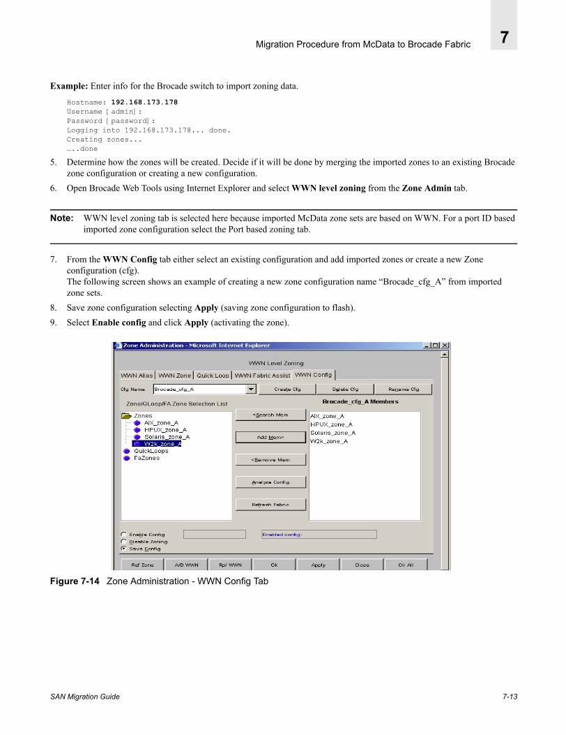
Migration Procedure from McData to Brocade Fabric 7
Example: Enter info for the Brocade switch to import zoning data.
Hostname: 192.168.173.178Username [admin]:Password [password]:Logging into 192.168.173.178... done.Creating zones...…..done
5. Determine how the zones will be created. Decide if it will be done by merging the imported zones to an existing Brocade zone configuration or creating a new configuration.
6. Open Brocade Web Tools using Internet Explorer and select WWN level zoning from the Zone Admin tab.
Note: WWN level zoning tab is selected here because imported McData zone sets are based on WWN. For a port ID based imported zone configuration select the Port based zoning tab.
7. From the WWN Config tab either select an existing configuration and add imported zones or create a new Zone configuration (cfg).The following screen shows an example of creating a new zone configuration name “Brocade_cfg_A” from imported zone sets.
8. Save zone configuration selecting Apply (saving zone configuration to flash).9. Select Enable config and click Apply (activating the zone).
Figure 7-14 Zone Administration - WWN Config Tab
SAN Migration Guide 7-13

Migration Procedure from McData to Brocade Fabric7
Brocade Fabric A Zone configuration name “Brocade_cfg_A” is created with imported McData zones.
Example: Cfgshow showing imported McData Zones
domain_01> cfgshowEffective configuration: cfg: Brocade_cfg_A zone: AIX_zone_A 10:00:00:00:c9:2f:1d:1d 50:06:04:82:c3:a0:75:b3 zone: HPUX_zone_A 50:06:04:82:c3:a0:75:9d 50:06:0b:00:00:08:fe:34 zone: Solaris_zone_A 10:00:00:00:c9:2f:20:71 50:06:04:82:c3:a0:75:8d zone: W2k_zone_A 10:00:00:00:c9:24:4e:b1 50:06:04:82:c3:a0:75:bb
Alternate Zone Set Transfer Methods(1) Creating zones from Telnet CLI:
A zoning configuration with a few zones can be manually keyed in from telnet CLI in advance, without having the device attached to the switch. However, this method is not recommended for a zone configuration with a large number of zones. The following example shows duplicating “McData_cfg_A” zone configuration to Brocade zone configuration “Brocade_cfg_A”.
1. Obtain zone list from McData switch (Telnet CLI command: Config zoning ShowActive)
Example: McData Zone list
Root> Config zoning ShowActiveActive Zone SetDefault Zone Enabled: FalseZone Set: McData_cfg_A Zone: Solaris_zone_A Zone Member: 10:00:00:00:C9:2F:20:71 Zone Member: 50:06:04:82:C3:A0:75:8D Zone: AIX_zone_A Zone Member: 10:00:00:00:C9:2F:1D:1D Zone Member: 50:06:04:82:C3:A0:75:B3 Zone: W2k_zone_A Zone Member: 10:00:00:00:C9:24:4E:B1 Zone Member: 50:06:04:82:C3:A0:75:BB Zone: HPUX_zone_A Zone Member: 50:06:04:82:C3:A0:75:9D Zone Member: 50:06:0B:00:00:08:FE:34
2. Open a telnet session on the Brocade switch and create identical zones and add the World Wide Port Name of the members.
Example: Creating Zones on a SilkWorm Switch
zoneCreate "Solaris_zone_A","10:00:00:00:c9:2f:20:71;50:06:04:82:c3:a0:75:8d"zoneCreate "AIX_zone_A',"10:00:00:00:c9:2f:1d:1d;50:06:04:82:c3:a0:75:b3"zoneCreate "W2k_zone_A","10:00:00:00:c9:24:4e:b1;50:06:04:82:c3:a0:75:bb"ZoneCreate "HPUX_zone_A","50:06:04:82:c3:a0:75:9d;50:06:0b:00:00:08:fe:34"
7-14 SAN Migration Guide

Migration Procedure from McData to Brocade Fabric 7
3. Create a Zone Configuration and add member zones, save and enable the Zone configuration.
Example: Adding Members and Enabling a Zone Configuration
cfgCreate "Brocade_cfg_A","solaris_zone_A;AIX_zone_A;w2k_zone_A;HPUX_zone_A"
domain_01:root> cfgsaveupdating flash ...domain_01:root> cfgEnable "Brocade_cfg_A"zone config "Brocade_cfg_A" is in effectUpdating flash ...domain_01:root> cfgshowEffective configuration: cfg: Brocade_cfg_A zone: AIX_zone_A 10:00:00:00:c9:2f:1d:1d 50:06:04:82:c3:a0:75:b3 zone: HPUX_zone_A 50:06:04:82:c3:a0:75:9d 50:06:0b:00:00:08:fe:34 zone: Solaris_zone_A 10:00:00:00:c9:2f:20:71 50:06:04:82:c3:a0:75:8d zone: W2k_zone_A 10:00:00:00:c9:24:4e:b1 50:06:04:82:c3:a0:75:bb
(2) Brocade Web Tools
Brocade Web Tools provides an easy to use interface. A zone can be created and zone members can be added by selecting the WWPN and clicking the Add members button. The WWPN for a device becomes available via the nameserver when the device is actually logged into fabric switch port.
This method is useful only if the advance preparation of Brocade Zoning is not a critical factor. The devices must be connected to the fabric port in order to retrieve the WWPN from the fabric nameserver. Thus the zoning Configuration can be created, saved and made effective only after the devices are present.
1. Perform IO failover from McData Fabric A to Fabric B in a redundant fabric environment.
2. Move device connections from McData Fabric A to Brocade Fabric A.
3. Open Brocade Web Tools. Select WWN level zoning from the zone admin tab.
4. Select the WWN zone tab and create a zone and add zone members by selecting the WWPN of the member and clicking on Add Mem button. (Create zones, AIX_zone_A, HPUX_zone_A, Solaris_zone_A and W2k_zone_A)
SAN Migration Guide 7-15

Migration Procedure from McData to Brocade Fabric7
Figure 7-15 Creating new zone name “W2k_zone_A” and adding member’s WWN.
5. From the WWN Config tab, either select an existing zone Configuration and modify it by including newly created zones or create a new Brocade Fabric A zone configuration “Brocade_cfg_A” and include the newly created zones.
6. Save the zone configuration by clicking the Apply tab. (Saving zone configuration to flash.)
7. Click the Enable config button and click Apply. (Activating the zone configuration.)
7-16 SAN Migration Guide

Migration Procedure from McData to Brocade Fabric 7
Figure 7-16 Creating a WWN Configuration name “Brocade_cfg_A”, saving and enabling the configuration
7.2.5. Step 5: Moving Devices to the Brocade FabricFrom the SANpilot Configuration menu, block (disable) the ports port by checking port box and clicking the Activate button for Solaris, Windows and AIX hosts.
Warning: DO NOT DISABLE or DISCONNECT HP-UX HOST and STORAGE PORT on McData Fabric A.
HPUX requires removal of physical link to a volume while it is still active. Please refer to Step 6: Restoring the Closed Path on the Brocade Fabric on page 7-21. First perform steps 1-3 to remove the hardware link of Mcdata Fabric A for each volume from their respective volume group. Failure to follow the exact procedure step by step will result in an un-recovered path on Brocade fabric A.
Powerpath will detect the closed port status and after a time-out period redirect all IOs to an available open port. Monitor the path status on the Powerpath “Powermt display” window. After the path is declared closed /failed /degraded, move the host connection on all other OS platforms except HPUX.
SAN Migration Guide 7-17
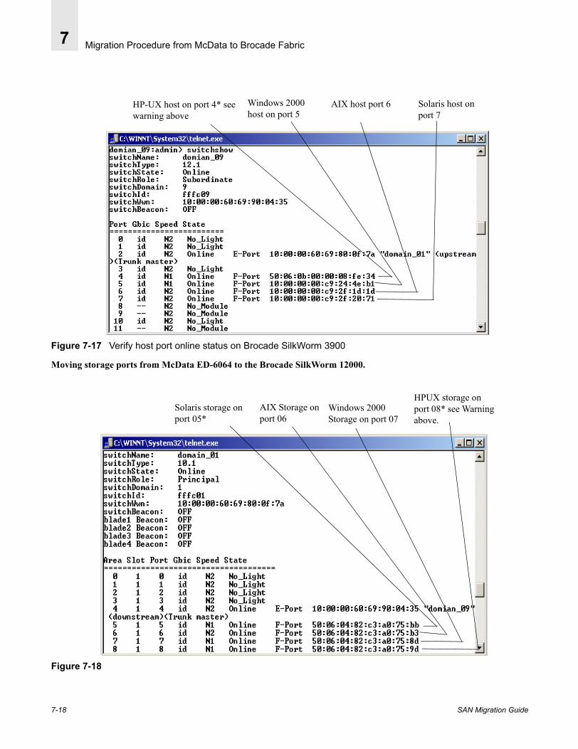
Migration Procedure from McData to Brocade Fabric7
Figure 7-17 Verify host port online status on Brocade SilkWorm 3900
Moving storage ports from McData ED-6064 to the Brocade SilkWorm 12000.
Figure 7-18
HP-UX host on port 4* see warning above
Windows 2000 host on port 5
AIX host port 6 Solaris host on port 7
Solaris storage on port 05*
AIX Storage on port 06
Windows 2000 Storage on port 07
HPUX storage on port 08* see Warning above.
7-18 SAN Migration Guide

Migration Procedure from McData to Brocade Fabric 7
Monitoring Fibre Channel port open/close status from Powermt display window
(Command > powermt display every=10)
Figure 7-19 EMC storage path FA-14aA is closed for Solaris host
Figure 7-20 All IOs are redirected to alternate open path FA-3bB
SAN Migration Guide 7-19

Migration Procedure from McData to Brocade Fabric7
Figure 7-21 EMC storage path FA-14aA is closed for AIX host.
Figure 7-22 All IOs are redirected to open path FA -3bB
Figure 7-23 EMC storage path is closed for the Windows 2000 host. All IOs are directed to the open port.
7-20 SAN Migration Guide
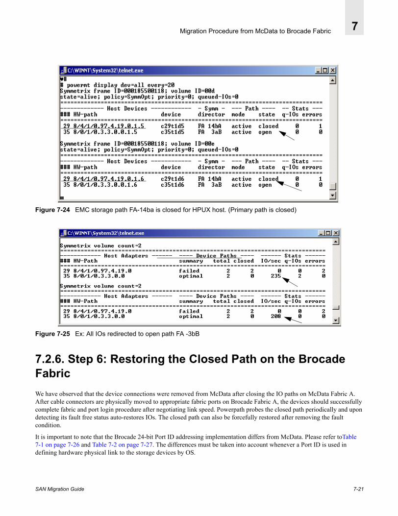
Migration Procedure from McData to Brocade Fabric 7
Figure 7-24 EMC storage path FA-14ba is closed for HPUX host. (Primary path is closed)
Figure 7-25 Ex: All IOs redirected to open path FA -3bB
7.2.6. Step 6: Restoring the Closed Path on the Brocade FabricWe have observed that the device connections were removed from McData after closing the IO paths on McData Fabric A. After cable connectors are physically moved to appropriate fabric ports on Brocade Fabric A, the devices should successfully complete fabric and port login procedure after negotiating link speed. Powerpath probes the closed path periodically and upon detecting its fault free status auto-restores IOs. The closed path can also be forcefully restored after removing the fault condition.
It is important to note that the Brocade 24-bit Port ID addressing implementation differs from McData. Please refer toTable 7-1 on page 7-26 and Table 7-2 on page 7-27. The differences must be taken into account whenever a Port ID is used in defining hardware physical link to the storage devices by OS.
SAN Migration Guide 7-21

Migration Procedure from McData to Brocade Fabric7
Restoring Close Path on Solaris HostPowerpath auto-restore feature restore path upon detecting open and restore IOs (no action is required assuming Persistent binding is done by WWPN).
Note: In case Persistent binding is done by Port ID, the HBA configuration file binding entry must be updated to reflect the correct 24-bit port ID followed by a Solaris host reboot.
Figure 7-26 EMC storage path FA-14aA is auto-restored for Solaris host.
Figure 7-27 IOs are restored on recovered path FA-14aA for Solaris host
7-22 SAN Migration Guide
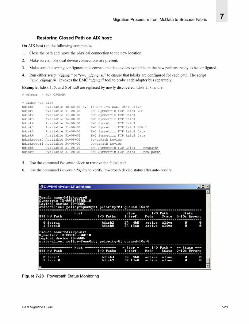
Migration Procedure from McData to Brocade Fabric 7
Restoring Closed Path on AIX host:On AIX host run the following commands.
1. Close the path and move the physical connection to the new location.
2. Make sure all physical device connections are present.
3. Make sure the zoning configuration is correct and the devices available on the new path are ready to be configured.
4. Run either script “cfgmgr” or “emc_cfgmgr.sh” to ensure that hdisks are configured for each path. The script “emc_cfgmgr.sh” invokes the EMC “cfgmgr” tool to probe each adapter bus separately.
Example: hdisk 1, 5, and 6 of fcs0 are replaced by newly discovered hdisk 7, 8, and 9.
# cfgmgr ( RUN CFGMGR)
# lsdev -Cc diskhdisk0 Available 40-60-00-4,0 16 Bit LVD SCSI Disk Drivehdisk1 Available 31-08-01 EMC Symmetrix FCP Raid1 VCMhdisk2 Available 34-08-01 EMC Symmetrix FCP Raid1hdisk3 Available 34-08-01 EMC Symmetrix FCP Raid1hdisk4 Available 34-08-01 EMC Symmetrix FCP Raid1hdisk7 Available 31-08-01 EMC Symmetrix FCP Raid1 VCM *hdisk5 Available 31-08-01 EMC Symmetrix FCP Raid1 Datahdisk6 Available 31-08-01 EMC Symmetrix FCP Raid1 Datahdiskpower0 Available 34-08-01 PowerPath Devicehdiskpower1 Available 34-08-01 PowerPath Devicehdisk8 Available 31-08-01 EMC Symmetrix FCP Raid1 newpath*hdisk9 Available 31-08-01 EMC Symmetrix FCP Raid1 new path*
5. Use the command Powermt check to remove the failed path.
6. Use the command Powermt display to verify Powerpath device status after auto-restore.
Figure 7-28 Powerpath Status Monitoring
SAN Migration Guide 7-23

Migration Procedure from McData to Brocade Fabric7
Figure 7-29 IOs are restored on recovered path FA-13aA for AIX host
7. Remove hdisks using the command rmdev - dl.
Example: Removing hdisks 5, 6, and 1.
# rmdev -dl hdisk5hdisk5 deleted
# rmdev -dl hdisk6hdisk6 deleted
# rmdev -dl hdisk1hdisk1 deleted
# lsdev -Cc diskhdisk0 Available 40-60-00-4,0 16 Bit LVD SCSI Disk Drivehdisk2 Available 34-08-01 EMC Symmetrix FCP Raid1hdisk3 Available 34-08-01 EMC Symmetrix FCP Raid1hdisk4 Available 34-08-01 EMC Symmetrix FCP Raid1hdisk7 Available 31-08-01 EMC Symmetrix FCP Raid1hdiskpower0 Available 34-08-01 PowerPath Devicehdiskpower1 Available 34-08-01 PowerPath Devicehdisk8 Available 31-08-01 EMC Symmetrix FCP Raid1hdisk9 Available 31-08-01 EMC Symmetrix FCP Raid1#
7-24 SAN Migration Guide
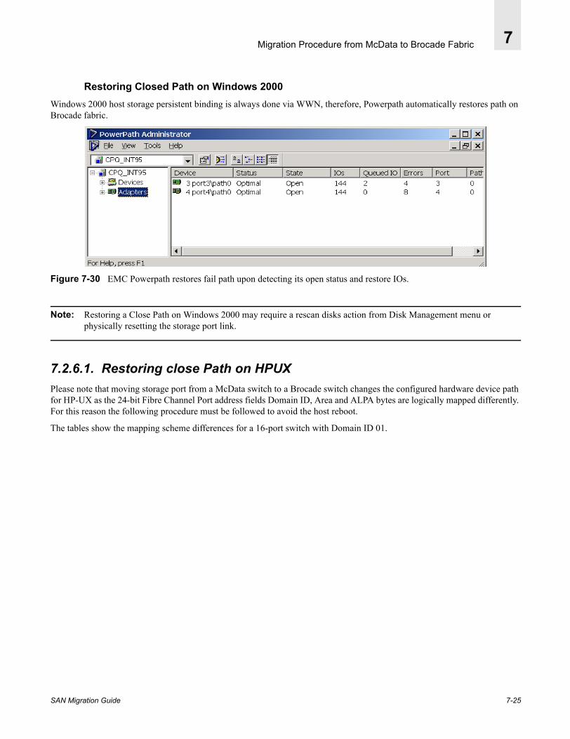
Migration Procedure from McData to Brocade Fabric 7
Restoring Closed Path on Windows 2000Windows 2000 host storage persistent binding is always done via WWN, therefore, Powerpath automatically restores path on Brocade fabric.
Figure 7-30 EMC Powerpath restores fail path upon detecting its open status and restore IOs.
Note: Restoring a Close Path on Windows 2000 may require a rescan disks action from Disk Management menu or physically resetting the storage port link.
7.2.6.1. Restoring close Path on HPUX Please note that moving storage port from a McData switch to a Brocade switch changes the configured hardware device path for HP-UX as the 24-bit Fibre Channel Port address fields Domain ID, Area and ALPA bytes are logically mapped differently. For this reason the following procedure must be followed to avoid the host reboot.
The tables show the mapping scheme differences for a 16-port switch with Domain ID 01.
SAN Migration Guide 7-25

Migration Procedure from McData to Brocade Fabric7
Example: A physical port 0 of a switch Domain ID 1 24-bit logical Fibre Channel Port ID for McData Switch =610413; Brocade switch=010000
Table 7-1
McData FC port ID bytes FC Port ID
SwitchPort #
Domain Area Al_PA 24bit Physical
61 04 13 610413 0
05 13 610513 1
06 13 610613 2
07 13 610713 3
08 13 610813 4
09 13 610913 5
0A 13 610A13 6
0B 13 610B13 7
0C 13 610C13 8
0D 13 610D13 9
0E 13 610E13 10
0F 13 610F13 11
10 13 611013 12
11 13 611113 13
12 13 611213 14
13 13 611313 15
7-26 SAN Migration Guide
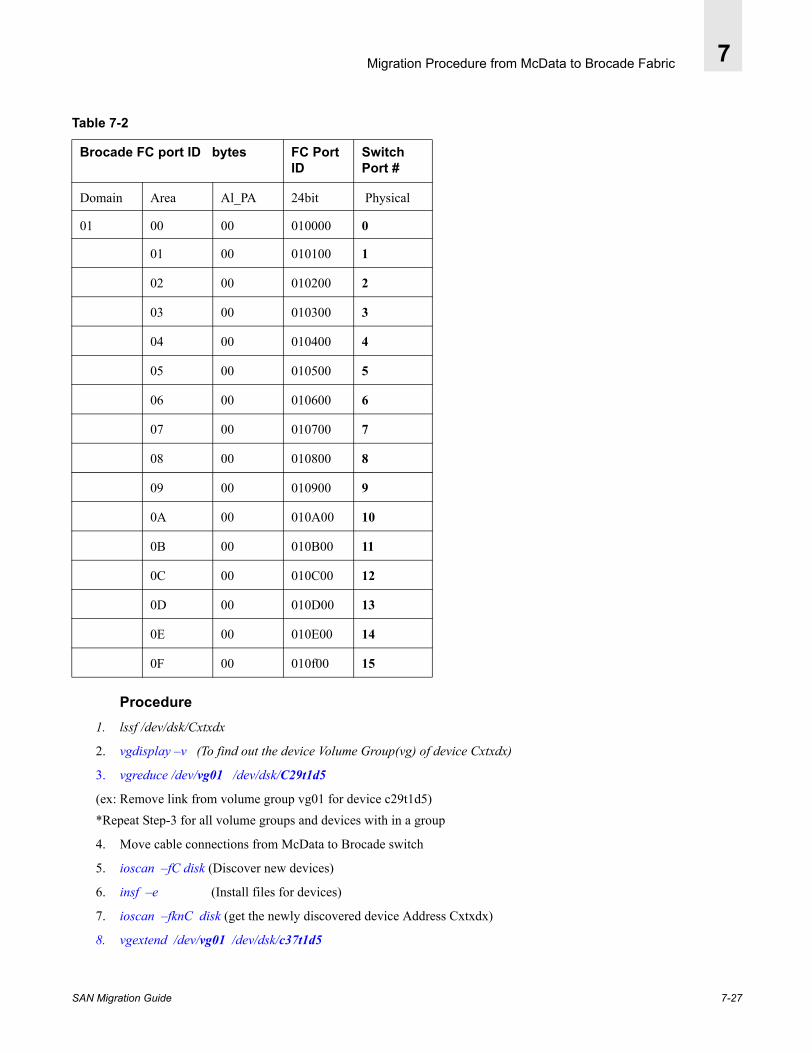
Migration Procedure from McData to Brocade Fabric 7
Table 7-2
Procedure 1. lssf /dev/dsk/Cxtxdx
2. vgdisplay –v (To find out the device Volume Group(vg) of device Cxtxdx)
3. vgreduce /dev/vg01 /dev/dsk/C29t1d5
(ex: Remove link from volume group vg01 for device c29t1d5)*Repeat Step-3 for all volume groups and devices with in a group
4. Move cable connections from McData to Brocade switch
5. ioscan –fC disk (Discover new devices)
6. insf –e (Install files for devices)
7. ioscan –fknC disk (get the newly discovered device Address Cxtxdx)
8. vgextend /dev/vg01 /dev/dsk/c37t1d5
Brocade FC port ID bytes FC Port ID
SwitchPort #
Domain Area Al_PA 24bit Physical
01 00 00 010000 0
01 00 010100 1
02 00 010200 2
03 00 010300 3
04 00 010400 4
05 00 010500 5
06 00 010600 6
07 00 010700 7
08 00 010800 8
09 00 010900 9
0A 00 010A00 10
0B 00 010B00 11
0C 00 010C00 12
0D 00 010D00 13
0E 00 010E00 14
0F 00 010f00 15
SAN Migration Guide 7-27

Migration Procedure from McData to Brocade Fabric7
(ex: Restore link to volume group vg01 for device c37t1d5)
*Repeat Step 8 for all volume groups and devices with in a group.
9. Powermt check (Powerpath status check)
10. Powermt config (update Config file)
ExampleThe following screen shows that Symmetrix Port FA-14ba path is configured for volume C29t1d5 and C29t1d6 on McData Fabric A which is about to change after the connections are moved to Brocade Fabric A.
Figure 7-31 Device hardware path configured via the McData switch for device for C29t1d5 and C29t1d6
1. Display configured hardware path for C29t1d5 and C29t1d6 devices.
Example:
# lssf /dev/dsk/c29t1d5sdisk card instance 29 SCSI target 1 SCSI LUN 5 section 0 at address 8/4/1/04.19.0.1.5 /dev/dsk/c29t1d5
# lssf /dev/dsk/c29t1d6sdisk card instance 29 SCSI target 1 SCSI LUN 6 section 0 at address 8/4/1/04.19.0.1.6 /dev/dsk/c29t1d6
2. Determine the volume group name of Device C29t1d5 and C29t1d6. from the output of the vgdisplay -v command. Device c29t1d5 belongs to volume group vg01Device C29t1d6 belongs to volume group vg02
Example: Output of the vgdisplay -v command
# vgdisplay -v--- Volume groups ---VG Name /dev/vg01VG Write Access read/writeVG Status available: --- Logical volumes --- LV Name /dev/vg01/vol01
7-28 SAN Migration Guide
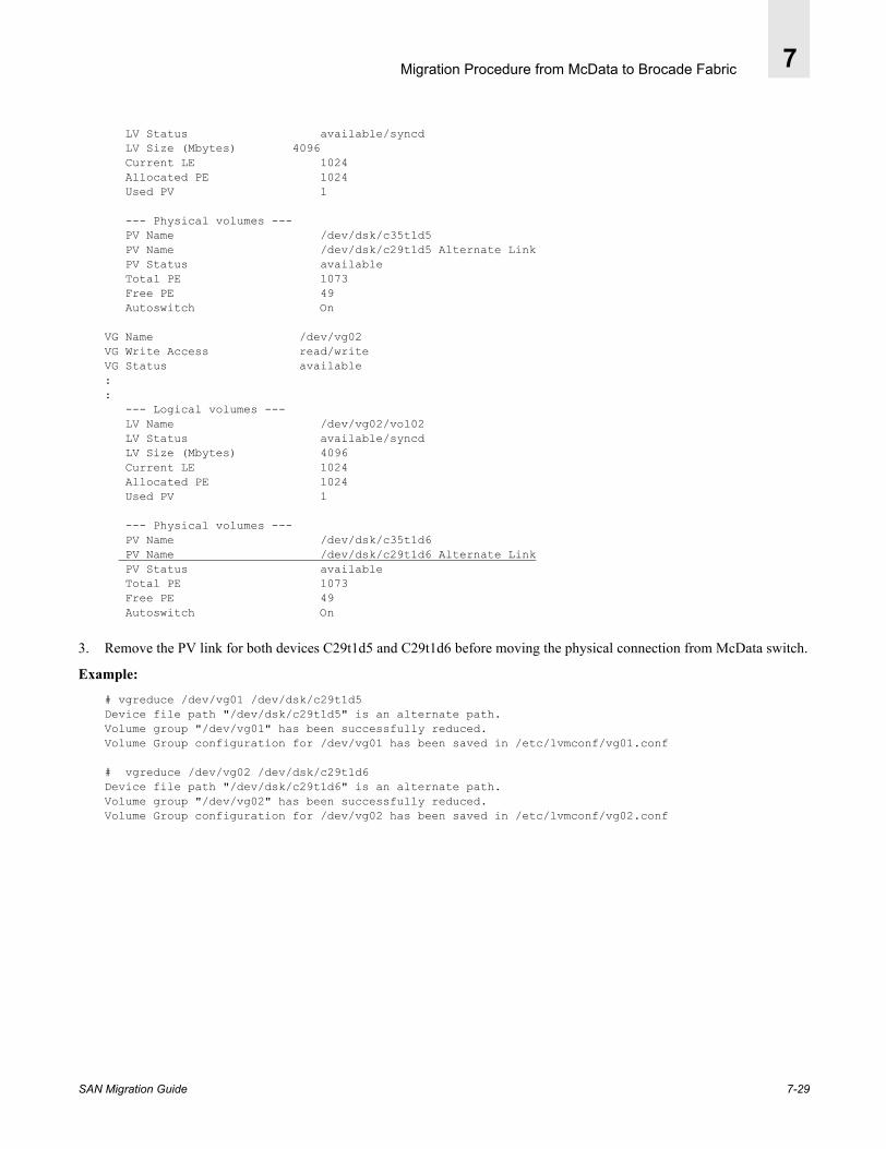
Migration Procedure from McData to Brocade Fabric 7
LV Status available/syncd LV Size (Mbytes) 4096 Current LE 1024 Allocated PE 1024 Used PV 1
--- Physical volumes --- PV Name /dev/dsk/c35t1d5 PV Name /dev/dsk/c29t1d5 Alternate Link PV Status available Total PE 1073 Free PE 49 Autoswitch On
VG Name /dev/vg02VG Write Access read/writeVG Status available:: --- Logical volumes --- LV Name /dev/vg02/vol02 LV Status available/syncd LV Size (Mbytes) 4096 Current LE 1024 Allocated PE 1024 Used PV 1
--- Physical volumes --- PV Name /dev/dsk/c35t1d6 PV Name /dev/dsk/c29t1d6 Alternate Link PV Status available Total PE 1073 Free PE 49 Autoswitch On
3. Remove the PV link for both devices C29t1d5 and C29t1d6 before moving the physical connection from McData switch.
Example:
# vgreduce /dev/vg01 /dev/dsk/c29t1d5Device file path "/dev/dsk/c29t1d5" is an alternate path.Volume group "/dev/vg01" has been successfully reduced.Volume Group configuration for /dev/vg01 has been saved in /etc/lvmconf/vg01.conf
# vgreduce /dev/vg02 /dev/dsk/c29t1d6Device file path "/dev/dsk/c29t1d6" is an alternate path.Volume group "/dev/vg02" has been successfully reduced.Volume Group configuration for /dev/vg02 has been saved in /etc/lvmconf/vg02.conf
SAN Migration Guide 7-29

Migration Procedure from McData to Brocade Fabric7
4. Close Port on McData switch and then move HPUX host and Storage port to the Brocade fabric.
Figure 7-32 McData Switch Fabric path is closed
Figure 7-33 All IOs are redirected to open path
5. Scan IO devices discover the new paths.
# ioscan -fC diskClass I H/W Path Driver S/W State H/W Type Description=============================================================disk 50 8/0/1/0.3.3.0.0.0.0 sdisk CLAIMED DEVICE EMC SYMMETRIXdisk 51 8/0/1/0.3.3.0.0.1.5 sdisk CLAIMED DEVICE EMC SYMMETRIXdisk 52 8/0/1/0.3.3.0.0.1.6 sdisk CLAIMED DEVICE EMC SYMMETRIXdisk 53 8/4/1/0.1.8.0.0.0.0 sdisk CLAIMED DEVICE EMC SYMMETRIXdisk 54 8/4/1/0.1.8.0.0.1.5 sdisk CLAIMED DEVICE EMC SYMMETRIXdisk 55 8/4/1/0.1.8.0.0.1.6 sdisk CLAIMED DEVICE EMC SYMMETRIXdisk 41 8/4/1/0.97.4.19.0.0.0 sdisk NO_HW DEVICE EMC SYMMETRIX *vcmdisk 42 8/4/1/0.97.4.19.0.1.5 sdisk NO_HW DEVICE EMC SYMMETRIXdisk 43 8/4/1/0.97.4.19.0.1.6 sdisk NO_HW DEVICE EMC SYMMETRIXdisk 0 8/16/5.2.0 sdisk CLAIMED DEVICE HP DVD-ROM304disk 1 8/16/5.6.0 sdisk CLAIMED DEVICE SEAGATE ST39216N
7-30 SAN Migration Guide

Migration Procedure from McData to Brocade Fabric 7
6. The command insf –e re-installs the special files for pseudo-drivers and existing devices. This is useful for restoring special files when one or more have been removed.
Example: The insf –e Command
# insf -e -C diskinsf: Installing special files for sdisk instance 50 address 8/0/1/0.3.3.0.0.0.0insf: Installing special files for sdisk instance 51 address 8/0/1/0.3.3.0.0.1.5insf: Installing special files for sdisk instance 52 address 8/0/1/0.3.3.0.0.1.6insf: Installing special files for sdisk instance 53 address 8/4/1/0.1.8.0.0.0.0 *vcminsf: Installing special files for sdisk instance 54 address 8/4/1/0.1.8.0.0.1.5insf: Installing special files for sdisk instance 55 address 8/4/1/0.1.8.0.0.1.6insf: Installing special files for sdisk instance 41 address 8/4/1/0.97.4.19.0.0.0insf: Installing special files for sdisk instance 42 address 8/4/1/0.97.4.19.0.1.5insf: Installing special files for sdisk instance 43 address 8/4/1/0.97.4.19.0.1.6insf: Installing special files for sdisk instance 0 address 8/16/5.2.0insf: Installing special files for sdisk instance 1 address 8/16/5.6.0
7. Get the device address Cxtxdx of newly configured devices to restore the path. The new devices configured on Brocade Fabric A are C37t1d5 and C37t1d6 (Please note that third device C37t0d0 is Symmetrix VCM database).
Example: Device Addresses
# ioscan -fknC disk
Class I H/W Path Driver S/W State H/W Type Description===================================================================disk 50 8/0/1/0.3.3.0.0.0.0 sdisk CLAIMED DEVICE EMC SYMMETRIX /dev/dsk/c35t0d0 /dev/rdsk/c35t0d0disk 51 8/0/1/0.3.3.0.0.1.5 sdisk CLAIMED DEVICE EMC SYMMETRIX /dev/dsk/c35t1d5 /dev/rdsk/c35t1d5disk 52 8/0/1/0.3.3.0.0.1.6 sdisk CLAIMED DEVICE EMC SYMMETRIX /dev/dsk/c35t1d6 /dev/rdsk/c35t1d6disk 53 8/4/1/0.1.8.0.0.0.0 sdisk CLAIMED DEVICE EMC SYMMETRIX /dev/dsk/c37t0d0 /dev/rdsk/c37t0d0disk 54 8/4/1/0.1.8.0.0.1.5 sdisk CLAIMED DEVICE EMC SYMMETRIX /dev/dsk/c37t1d5 /dev/rdsk/c37t1d5disk 55 8/4/1/0.1.8.0.0.1.6 sdisk CLAIMED DEVICE EMC SYMMETRIX /dev/dsk/c37t1d6 /dev/rdsk/c37t1d6disk 41 8/4/1/0.97.4.19.0.0.0 sdisk NO_HW DEVICE EMC SYMMETRIX /dev/dsk/c29t0d0 /dev/rdsk/c29t0d0disk 42 8/4/1/0.97.4.19.0.1.5 sdisk NO_HW DEVICE EMC SYMMETRIX /dev/dsk/c29t1d5 /dev/rdsk/c29t1d5disk 43 8/4/1/0.97.4.19.0.1.6 sdisk NO_HW DEVICE EMC SYMMETRIX /dev/dsk/c29t1d6 /dev/rdsk/c29t1d6disk 0 8/16/5.2.0 sdisk CLAIMED DEVICE HP DVD-ROM 304 /dev/dsk/c0t2d0 /dev/rdsk/c0t2d0disk 1 8/16/5.6.0 sdisk CLAIMED DEVICE SEAGATE ST39216N /dev/dsk/c0t6d0 /dev/rdsk/c0t6d0
8. Restore links on all newly discovered devices on the same volume group (Complementary to vgreduce command).
Example: Restore Links
# vgextend /dev/vg01 /dev/dsk/c37t1d5
Volume group “/dev/vg01” has been successfully extended.Volume Group configuration for /dev/vg01 has been saved in /etc/lvmconf/vg01f
# vgextend /dev/vg02 /dev/dsk/c37t1d6
Volume group “/dev/vg02” has been successfully extended.Volume Group configuration for /dev/vg02 has been saved in /etc/lvmconf/vg02f
SAN Migration Guide 7-31

Migration Procedure from McData to Brocade Fabric7
Figure 7-34
The McData link 8/4/1/0.97.4.19.0.1.5 is successfully replaced by the Brocade link8/4/1/0.1.0.1.5. The McData link 8/4/1/0.97.4.19.0.1.6 is successfully replaced by the Brocade link 8/4/1/0.1.0.1.6.
9. Powermt check (Powermt command)Warning: Symmetrix device path c29t1d5 is currently dead.Do you want to remove it (y/n/a/q)? yWarning: Symmetrix device path c29t1d6 is currently dead.Do you want to remove it (y/n/a/q)? y
Figure 7-35 Failed path is removed and new link is established on EMC Storage port_14ba
7-32 SAN Migration Guide
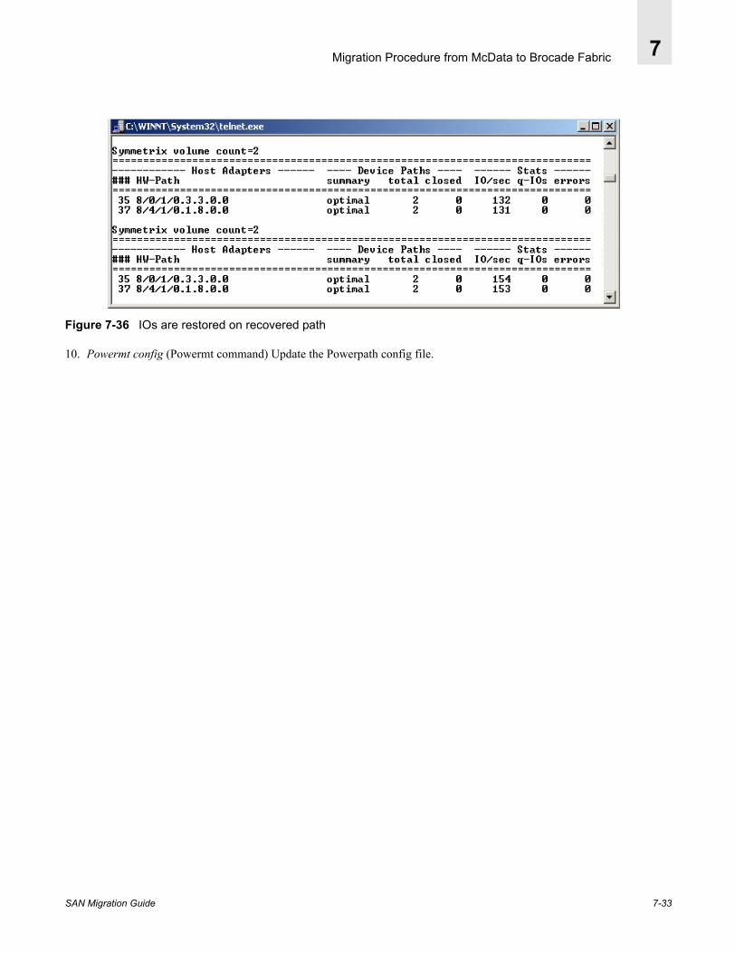
Migration Procedure from McData to Brocade Fabric 7
Figure 7-36 IOs are restored on recovered path
10. Powermt config (Powermt command) Update the Powerpath config file.
SAN Migration Guide 7-33

Migration Procedure from McData to Brocade Fabric7
7-34 SAN Migration Guide

SAN Migration Guide
Appendix
A
Operating System PlatformsThe following sections describe host setup for Sun Solaris-8, IBM AIX -4.3, HP-UX -11i and Windows-2000 platforms. All hosts are configured with a minimum of two hba accessing EMC Symmterix storage volumes, configured for redundant access using EMC host based Powerpath software package. Thus, an application running on a host can access storage via either path providing a fault tolerance in case a path actively processing IO operations is disrupted. During the entire migration process a script is executing Read and Write IO operations continuously comparing the readback data to verify data integrity
The operating system platforms used in the following case studies include:
• Sun Solaris-8 on page A-1.• IBM AIX 4.3 on page A-5.• HP-UX 11i on page A-7.• MS Windows 2000 Server on page A-12.
A.1. Sun Solaris-8Table A-1 shows a summary of host hardware and software configuration in Solaris-8 environment. Sun Sparc host is configured as per EMC hardware and software compatibility matrix.
EMC Symmetrix storage is upgraded to the most recent microcode version. Each hba is given access to the same two volumes via two different Symmetrix FA-ports using EMC ESN Manager 2.1. The storage volumes are discovered, partitioned and mounted to execute a file transfer script in the background.
A-1
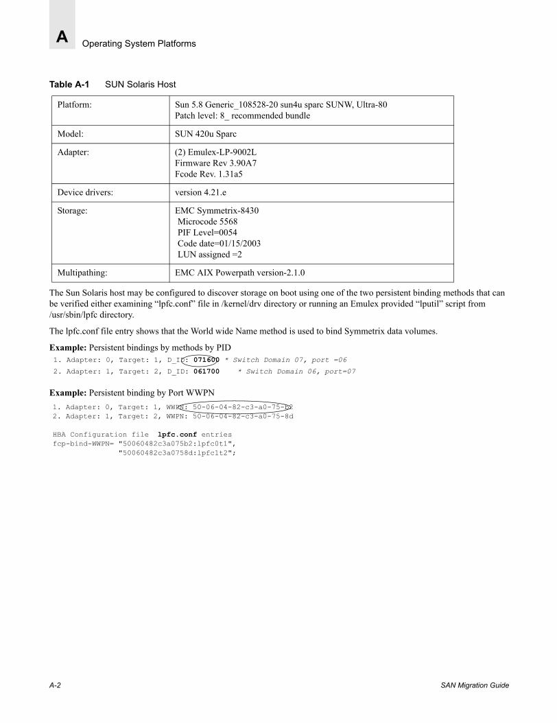
Operating System PlatformsA
Table A-1 SUN Solaris Host
The Sun Solaris host may be configured to discover storage on boot using one of the two persistent binding methods that can be verified either examining “lpfc.conf” file in /kernel/drv directory or running an Emulex provided “lputil” script from /usr/sbin/lpfc directory.
The lpfc.conf file entry shows that the World wide Name method is used to bind Symmetrix data volumes.
Example: Persistent bindings by methods by PID
Example: Persistent binding by Port WWPN
Platform: Sun 5.8 Generic_108528-20 sun4u sparc SUNW, Ultra-80 Patch level: 8_ recommended bundle
Model: SUN 420u Sparc
Adapter: (2) Emulex-LP-9002LFirmware Rev 3.90A7Fcode Rev. 1.31a5
Device drivers: version 4.21.e
Storage: EMC Symmetrix-8430Microcode 5568PIF Level=0054Code date=01/15/2003LUN assigned =2
Multipathing: EMC AIX Powerpath version-2.1.0
1. Adapter: 0, Target: 1, D_ID: 071600 * Switch Domain 07, port =06 2. Adapter: 1, Target: 2, D_ID: 061700 * Switch Domain 06, port=07
1. Adapter: 0, Target: 1, WWPN: 50-06-04-82-c3-a0-75-b22. Adapter: 1, Target: 2, WWPN: 50-06-04-82-c3-a0-75-8d
HBA Configuration file lpfc.conf entries fcp-bind-WWPN= "50060482c3a075b2:lpfc0t1",
"50060482c3a0758d:lpfc1t2";
A-2 SAN Migration Guide

Operating System Platforms A
A format command discovers pre-assigned two Symmetrix data volumes and VCM (Volume Logix database volume) on each FC host adapter C2 and C3. Powerpath configures these volumes emcpower1a and emcpower2a pseudo devices.
Example: Format command output after installing Powerpath:
EMC Powerpath software operations are configured and monitor via “powermt” commands. A “powermt display” command with appropriate option can be used to monitor link status.
The two data volumes 01 and 02 volume access is configured via Symmetrix ports FA-3bB and FA-14aA. Powerpath has configured both HBAs in active mode meaning both paths are open for IO operations.
Example: EMC Powerpath Status Monitoring
AVAILABLE DISK SELECTIONS: 0. c0t0d0 <SUN18G cyl 7506 alt 2 hd 19 sec 248> /pci@1f,4000/scsi@3/sd@0,0 1. c0t1d0 <SUN36G cyl 24620 alt 2 hd 27 sec 107> /pci@1f,4000/scsi@3/sd@1,0 2. c2t1d0 <EMC-SYMMETRIX-5568 cyl 14 alt 2 hd 15 sec 64> /pci@1f,4000/lpfc@4/sd@1,0 3. c2t1d1 <EMC-SYMMETRIX-5567 cyl 9158 alt 2 hd 15 sec 64> /pci@1f,4000/lpfc@4/sd@1,1 4. c2t1d2 <EMC-SYMMETRIX-5567 cyl 9158 alt 2 hd 15 sec 64> /pci@1f,4000/lpfc@4/sd@1,2 5. c3t2d0 <EMC-SYMMETRIX-5568 cyl 14 alt 2 hd 15 sec 64> /pci@1f,2000/lpfc@1/sd@2,0 6. c3t2d1 <EMC-SYMMETRIX-5567 cyl 9158 alt 2 hd 15 sec 64> /pci@1f,2000/lpfc@1/sd@2,1 7. c3t2d2 <EMC-SYMMETRIX-5567 cyl 9158 alt 2 hd 15 sec 64> /pci@1f,2000/lpfc@1/sd@2,2
8. emcpower1a <EMC-SYMMETRIX-5567 cyl 9158 alt 2 hd 15 sec 64>/pseudo/emcp@1
9. emcpower2a <EMC-SYMMETRIX-5567 cyl 9158 alt 2 hd 15 sec 64> /pseudo/emcp@2
# powermt display dev=all
Pseudo name=emcpower1aSymmetrix frame ID=000185500118; volume ID=001state=alive; policy=SymmOpt; priority=0; queued-IOs=0=========================================================================------------- Host Devices ------------ - Symm - --- Path ---- -- Stats ---### HW-path device director mode state q-IOs errors========================================================================= 1 pci@1f,4000/lpfc@4 c2t1d1s0 FA 3bB active open 0 2 0 pci@1f,2000/lpfc@1 c3t2d1s0 FA 14aA active open 0 0
Pseudo name=emcpower2aSymmetrix frame ID=000185500118; volume ID=002state=alive; policy=SymmOpt; priority=0; queued-IOs=0=========================================================================------------- Host Devices ------------ - Symm - --- Path ---- -- Stats ---### HW-path device director mode state q-IOs errors========================================================================= 1 pci@1f,4000/lpfc@4 c2t1d2s0 FA 3bB active open 0 2 0 pci@1f,2000/lpfc@1 c3t2d2s0 FA 14aA active open 0 0
Mounted File Systems: symlun01 and symlun02
SAN Migration Guide A-3
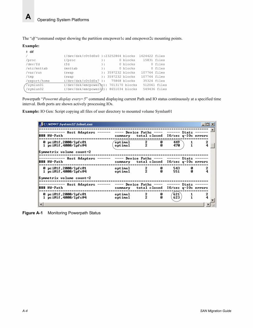
Operating System PlatformsA
The “df “command output showing the partition emcpower1c and emcpower2c mounting points.
Example:
Powerpath “Powermt display every=5” command displaying current Path and IO status continuously at a specified time interval. Both ports are shown actively processing IOs.
Example: IO Gen: Script copying all files of user directory to mounted volume Symlun01
Figure A-1 Monitoring Powerpath Status
# df/ (/dev/dsk/c0t0d0s0 ):23252864 blocks 1624422 files/proc (/proc ): 0 blocks 15831 files/dev/fd (fd ): 0 blocks 0 files/etc/mnttab (mnttab ): 0 blocks 0 files/var/run (swap ): 3597232 blocks 107764 files/tmp (swap ): 3597232 blocks 107764 files/export/home (/dev/dsk/c0t0d0s7 ): 75868 blocks 35324 files/symlun01 (/dev/dsk/emcpower1c): 7013170 blocks 512061 files/symlun02 (/dev/dsk/emcpower2c): 8651034 blocks 549436 files
A-4 SAN Migration Guide

Operating System Platforms A
A.2. IBM AIX 4.3Table A-2 shows a summary of host hardware and software configuration in AIX 4.3 OS environment. An IBM Pseries server is configured as per EMC hardware and software compatibility matrix. Two Emulex -LP9002 hba are configured using IBM specific emulex device drivers. Each hba is given access to the same two volumes via two different Symmetrix FA-ports. The storage volumes are discovered, partitioned and mounted to execute a file transfer script in the back ground continuously. The data integrity is monitored during entire migration process.
Table A-2 IBM AIX Host
“lsdev -Cc adapter | grep fc” command lists available Fibre Channel host bus adapters fcs0 and fcs1 prior to Symmetrix volume assignment.
Example: Listing Adapters
# lsdev -Cc adapter |grep fc
fcs0 Available 31-08 FC Adapterfcs1 Available 34-08 FC Adapter
Device drivers for Fc=C adapters Lp-9002L = IBM fcs0 driver =df1000f9
IBM provides a GUI based SMIT interface to list and configure device parameters. The following is an example of obtaining a detail information on an available hba using SMIT utility.
Example: Adapter Configuration: (SMIT output)
Platform: IBM AIX OS version 4.3.3 Maintenance level ML=11
Model: IBM Pseries server
Adapter: (2) Emulex-LP-9002L
Device drivers: IBM fcs0 driver=df1000f9
Storage: EMC Symmetrix-8430Microcode 5568PIF Level=0054Code date=01/15/2003LUN assigned =2
Multipathing: EMC AIX Powerpath version-3.0.2
FC Adapter fcs0Description FC AdapterStatuss0 Available 31-08 FC Adapter AvailableLocation Available 34-08 FC Adapter 31-08Maximum number of COMMANDS to queue to the adapter [200]Maximum Transfer Size F2=Refresh F[0x100000]Preferred AL_PA [0x1]Apply change to DATABASE only no
Storage: EMC Symmetrix-8430
Micro- code =5568 PIF Level =0054 code date =01/15/2003
SAN Migration Guide A-5
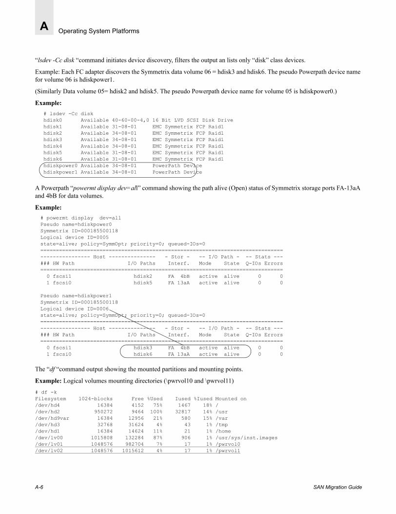
Operating System PlatformsA
“lsdev -Cc disk “command initiates device discovery, filters the output an lists only “disk” class devices.
Example: Each FC adapter discovers the Symmetrix data volume 06 = hdisk3 and hdisk6. The pseudo Powerpath device name for volume 06 is hdiskpower1.
(Similarly Data volume 05= hdisk2 and hdisk5. The pseudo Powerpath device name for volume 05 is hdiskpower0.)
Example:
A Powerpath “powermt display dev=all” command showing the path alive (Open) status of Symmetrix storage ports FA-13aA and 4bB for data volumes.
Example:
The “df “command output showing the mounted partitions and mounting points.
Example: Logical volumes mounting directories (\pwrvol10 and \pwrvol11)
# df -kFilesystem 1024-blocks Free %Used Iused %Iused Mounted on/dev/hd4 16384 4152 75% 1467 18% //dev/hd2 950272 9464 100% 32817 14% /usr/dev/hd9var 16384 12956 21% 580 15% /var/dev/hd3 32768 31624 4% 43 1% /tmp/dev/hd1 16384 14624 11% 21 1% /home/dev/lv00 1015808 132284 87% 906 1% /usr/sys/inst.images/dev/lv01 1048576 982704 7% 17 1% /pwrvol0/dev/lv02 1048576 1015612 4% 17 1% /pwrvol1
# lsdev -Cc diskhdisk0 Available 40-60-00-4,0 16 Bit LVD SCSI Disk Drivehdisk1 Available 31-08-01 EMC Symmetrix FCP Raid1hdisk2 Available 34-08-01 EMC Symmetrix FCP Raid1hdisk3 Available 34-08-01 EMC Symmetrix FCP Raid1hdisk4 Available 34-08-01 EMC Symmetrix FCP Raid1hdisk5 Available 31-08-01 EMC Symmetrix FCP Raid1hdisk6 Available 31-08-01 EMC Symmetrix FCP Raid1hdiskpower0 Available 34-08-01 PowerPath Devicehdiskpower1 Available 34-08-01 PowerPath Device
# powermt display dev=allPseudo name=hdiskpower0Symmetrix ID=000185500118Logical device ID=0005state=alive; policy=SymmOpt; priority=0; queued-IOs=0==============================================================================---------------- Host --------------- - Stor - -- I/O Path - -- Stats ---### HW Path I/O Paths Interf. Mode State Q-IOs Errors============================================================================== 0 fscsi1 hdisk2 FA 4bB active alive 0 0 1 fscsi0 hdisk5 FA 13aA active alive 0 0
Pseudo name=hdiskpower1Symmetrix ID=000185500118Logical device ID=0006state=alive; policy=SymmOpt; priority=0; queued-IOs=0==============================================================================---------------- Host --------------- - Stor - -- I/O Path - -- Stats ---### HW Path I/O Paths Interf. Mode State Q-IOs Errors============================================================================== 0 fscsi1 hdisk3 FA 4bB active alive 0 0 1 fscsi0 hdisk6 FA 13aA active alive 0 0
A-6 SAN Migration Guide
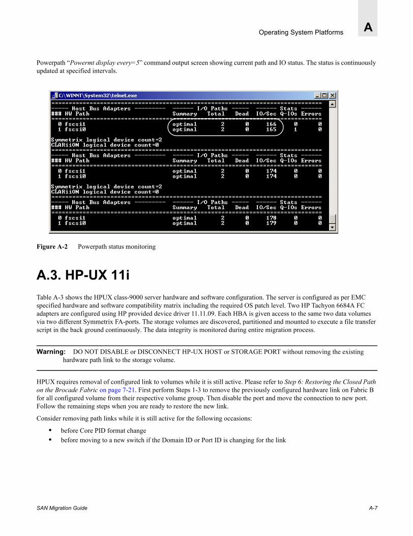
Operating System Platforms A
Powerpath “Powermt display every=5” command output screen showing current path and IO status. The status is continuously updated at specified intervals.
Figure A-2 Powerpath status monitoring
A.3. HP-UX 11iTable A-3 shows the HPUX class-9000 server hardware and software configuration. The server is configured as per EMC specified hardware and software compatibility matrix including the required OS patch level. Two HP Tachyon 6684A FC adapters are configured using HP provided device driver 11.11.09. Each HBA is given access to the same two data volumes via two different Symmetrix FA-ports. The storage volumes are discovered, partitioned and mounted to execute a file transfer script in the back ground continuously. The data integrity is monitored during entire migration process.
Warning: DO NOT DISABLE or DISCONNECT HP-UX HOST or STORAGE PORT without removing the existing hardware path link to the storage volume.
HPUX requires removal of configured link to volumes while it is still active. Please refer to Step 6: Restoring the Closed Path on the Brocade Fabric on page 7-21. First perform Steps 1-3 to remove the previously configured hardware link on Fabric B for all configured volume from their respective volume group. Then disable the port and move the connection to new port. Follow the remaining steps when you are ready to restore the new link.
Consider removing path links while it is still active for the following occasions:
• before Core PID format change• before moving to a new switch if the Domain ID or Port ID is changing for the link
SAN Migration Guide A-7

Operating System PlatformsA
Table A-3 HP-UX Host
Example: “ioscan -FNCc fc” showing the claimed FC adpater0 and adapter1 and configured paths.
“ioscan -FnC disk” command discovers and shows pre-assigned two Symmetrix data volumes 05, 06 and VCM (Symmetrix Volume logix database) on each adapter.
Platform: HP-UX B.11.11 64bit OS Patches - Feb 2001 bundle 11i
Model: r-class-9000 (D380)
Adapter: (2) HP Tachyon 6684A FC adapters
Device drivers: 11.11.09
Storage: EMC Symmetrix-8430
Microcode 5568PIF Level=0054Code date=01/15/2003LUN assigned =2
Multipathing: EMC HPUX Powerpath version-2.1.0_b108
# ioscan -FnC fc pci:fcms:F:T:F:-1:26:4294967295:fc:td:8/0/1/0:16 60 16 40 0 255 240 0 :0:root.ccio.GSCtoPCI.td:td:CLAIMED:INTERFACE:HP Tachyon TL/TS Fibre Channel Mass StorageAdapter:0 /dev/td0
pci:fcms:F:T:F:-1:26:4294967295:fc:td:8/4/1/0:16 60 16 40 0 255 240 0 :1:root.ccio.GSCtoPCI.td:td:CLAIMED:INTERFACE:HP Tachyon TL/TS Fibre Channel Mass StorageAdapter:1 /dev/td1
A-8 SAN Migration Guide

Operating System Platforms A
Example:
Example: “Ioscan -C disk” command showing only the hardware path link for disk class devices. A 24-bit address of the Fibre Channel switch port where the disk storage is connected to also embedded in the hardware path. HP-UX applies a Port ID based storage binding.
# ioscan -FnC disk (Disk discovery)csi:wsio:T:T:F:31:188:131072:disk:sdisk:8/0/1/0.7.20.0.0.0.0:0 0 2 18 0 0 0 0 17 152 137 45 136 18 23 176 :2:root.ccio.GSCtoPCI.td.fcp.fcparray.tgt.sdisk:sdis:CLAIMED:DEVICE:EMC SYMMETRIX:2 /dev/dsk/c2t0d0 /dev/rdsk/c2t0d0csi:wsio:T:T:F:31:188:136448:disk:sdisk:8/0/1/0.7.20.0.0.1.5:0 0 2 18 0 0 0 0 17 152 137 45 246 30 26 5 :4:root.ccio.GSCtoPCI.td.fcp.fcparray.tgt.sdisk:sdisk:LAIMED:DEVICE:EMC SYMMETRIX:2 /dev/dsk/c2t1d5 /dev/rdsk/c2t1d5csi:wsio:T:T:F:31:188:136704:disk:sdisk:8/0/1/0.7.20.0.0.1.6:0 0 2 18 0 0 0 0 17 152 137 45 110 147 236 51 :5:root.ccio.GSCtoPCI.td.fcp.fcparray.tgt.sdisk:sdik:CLAIMED:DEVICE:EMC SYMMETRIX:2 /dev/dsk/c2t1d6 /dev/rdsk/c2t1d6csi:wsio:T:T:F:31:188:786432:disk:sdisk:8/4/1/0.9.19.0.0.0.0:0 0 2 18 0 0 0 0 17 152 137 45 136 18 23 176 :17:root.ccio.GSCtoPCI.td.fcp.fcparray.tgt.sdisk:sdik:CLAIMED:DEVICE:EMC SYMMETRIX:12 /dev/dsk/c12t0d0 /dev/rdsk/c12t0d0csi:wsio:T:T:F:31:188:791808:disk:sdisk:8/4/1/0.9.19.0.0.1.5:0 0 2 18 0 0 0 0 17 152 137 45 246 30 26 5 :18:root.ccio.GSCtoPCI.td.fcp.fcparray.tgt.sdisk:sdiskCLAIMED:DEVICE:EMC SYMMETRIX:12 /dev/dsk/c12t1d5 /dev/rdsk/c12t1d5csi:wsio:T:T:F:31:188:792064:disk:sdisk:8/4/1/0.9.19.0.0.1.6:0 0 2 18 0 0 0 0 17 152 137 45 110 147 236 51 :19:root.ccio.GSCtoPCI.td.fcp.fcparray.tgt.sdisk:sdsk:CLAIMED:DEVICE:EMC SYMMETRIX:12 /dev/dsk/c12t1d6 /dev/rdsk/c12t1d6csi:wsio:T:T:F:31:188:8192:disk:sdisk:8/16/5.2.0:5 128 2 66 0 0 0 0 204 34 1877 0 0 0 0 :0:root.ccio.bus_adapter.c720.tgt.sdisk:sdisk:CLAIMED:DEVICE:HPVD-ROM 304:0 /dev/dsk/c0t2d0 /dev/rdsk/c0t2d0csi:wsio:T:T:F:31:188:24576:disk:sdisk:8/16/5.6.0:0 0 3 18 0 0 0 0 237 219 16223 41 54 6 82 :1:root.ccio.bus_adapter.c720.tgt.sdisk:sdisk:CLAIMED:DEVICE:SEAGTE ST39216N:0 /dev/dsk/c0t6d0 /dev/rdsk/c0t6d0
Symmetrix VCM volume
Symmetrix Data volume
Symmetrix Data volume
# ioscan -C disk H/W Path Class Description===============================================================8/0/1/0.7.20.0.0.0.0 disk EMC SYMMETRIX8/0/1/0.7.20.0.0.1.5 disk EMC SYMMETRIX8/0/1/0.7.20.0.0.1.6 disk EMC SYMMETRIX8/4/1/0.9.19.0.0.0.0 disk EMC SYMMETRIX8/4/1/0.9.19.0.0.1.5 disk EMC SYMMETRIX8/4/1/0.9.19.0.0.1.6 disk EMC SYMMETRIX8/16/5.2.0 disk HP DVD-ROM 3048/16/5.6.0 disk SEAGATE ST39216N
8/0/1/0.7.20.0.0.0.0 Storage port bindings Adapter 0 (switch domain ID 7, port=4*)
8/4/1/0.9.19.0.0.0.0 Storage port bindings Adapter 1 (switch domain ID9, port=3*)
*24-bit Port address, Area field for switch port 4 and 3 are setup for 14 hex (20 Decimal,) and 13 hex (19 Decimal.) respectively on Brocade SilkWorm Core PID Format-0.
SAN Migration Guide A-9

Operating System PlatformsA
SAM utility can be used to create logical volume (lvm), volume group (vg), installing file system and creating a mounting point.
The following SAM screen shows the current symmetrix volume configuration. For example: a logical volume (lvm) symvol01 belongs to a volume group (vg) symgrp00. Installed file system type is vxFS and mounting point is /gs/mntvol1
Example:
------------------------------------------------------------Logical Volumes 0 of 10 selected------------------------------------------------------------ Total Mirror Mou Logical Volume Volume Group Type Use Mbytes Copies Dir+----------------------------------------------------------- lvol1 vg00 LVM HFS 300 0 /sta ^ lvol2 vg00 LVM Swap/Dump256 0 lvol3 vg00 LVM VxFS 200 0 / lvol4 vg00 LVM VxFS 200 0 /tmp lvol5 vg00 LVM VxFS 20 0 /hom lvol6 vg00 LVM VxFS 808 0 /opt lvol7 vg00 LVM VxFS 1036 0 /usr lvol8 vg00 LVM VxFS 756 0 /var symvol01 symgrp00 LVM VxFS 4096 0 /gs/ symvol02 symgrp01 LVM VxFS 4096 0 /gs/
Example: Powerpath “powermt display dev=all” command showing the current status of data volume paths. # powermt display dev=allSymmetrix frame ID=000185500118; volume ID=0dstate=alive; policy=SymmOpt; priority=0; queued-IOs=0=========================================================================------------- Host Devices ------------ - Symm - --- Path ---- -- Stats ---### HW-path device director mode state q-IOs errors============================================================================== 12 8/4/1/0.9.19.0.0.1.5 c12t1d5 FA 14bA active open 0 0 2 8/0/1/0.7.20.0.0.1.5 c2t1d5 FA 3aB active open 0 0Symmetrix frame ID=000185500118; volume ID=0estate=alive; policy=SymmOpt; priority=0; queued-IOs=0=========================================================================------------- Host Devices ------------ - Symm - --- Path ---- -- Stats ---### HW-path device director mode state q-IOs errors========================================================================= 12 8/4/1/0.9.19.0.0.1.6 c12t1d6 FA 14bA active open 0 0 2 8/0/1/0.7.20.0.0.1.6 c2t1d6 FA 3aB active open 0 0
A-10 SAN Migration Guide
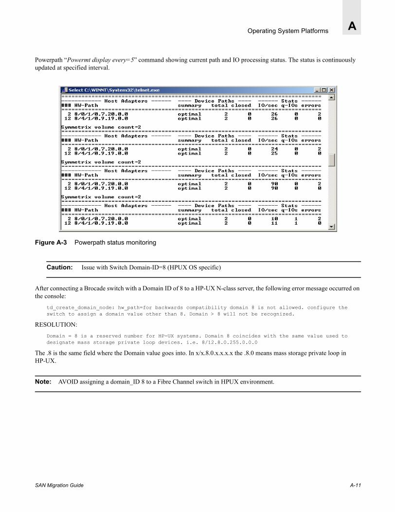
Operating System Platforms A
Powerpath “Powermt display every=5” command showing current path and IO processing status. The status is continuously updated at specified interval.
Figure A-3 Powerpath status monitoring
Caution: Issue with Switch Domain-ID=8 (HPUX OS specific)
After connecting a Brocade switch with a Domain ID of 8 to a HP-UX N-class server, the following error message occurred on the console:
td_create_domain_node: hw_path=for backwards compatibility domain 8 is not allowed. configure the switch to assign a domain value other than 8. Domain > 8 will not be recognized.
RESOLUTION:
Domain = 8 is a reserved number for HP-UX systems. Domain 8 coincides with the same value used to designate mass storage private loop devices. i.e. 8/12.8.0.255.0.0.0
The .8 is the same field where the Domain value goes into. In x/x.8.0.x.x.x.x the .8.0 means mass storage private loop in HP-UX.
Note: AVOID assigning a domain_ID 8 to a Fibre Channel switch in HPUX environment.
SAN Migration Guide A-11
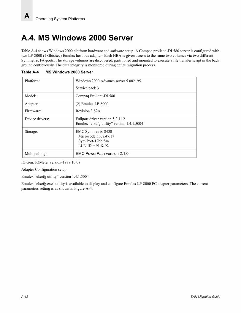
Operating System PlatformsA
A.4. MS Windows 2000 ServerTable A-4 shows Windows 2000 platform hardware and software setup. A Compaq proliant -DL580 server is configured with two LP-8000 (1 Gbit/sec) Emulex host bus adapters Each HBA is given access to the same two volumes via two different Symmetrix FA-ports. The storage volumes are discovered, partitioned and mounted to execute a file transfer script in the back ground continuously. The data integrity is monitored during entire migration process.
Table A-4 MS Windows 2000 Server
IO Gen: IOMeter version-1989.10.08
Adapter Configuration setup:
Emulex “elxcfg utility” version 1.4.1.5004
Emulex “elxcfg.exe” utility is available to display and configure Emulex LP-8000 FC adapter parameters. The current parameters setting is as shown in Figure A-4.
Platform: Windows 2000 Advance server 5.002195
Service pack 3
Model: Compaq Proliant-DL580
Adapter:
Firmware:
(2) Emulex LP-8000
Revision 3.82A
Device drivers: Fullport driver version 5.2.11.2Emulex “elxcfg utility” version 1.4.1.5004
Storage: EMC Symmetrix-8430Microcode 5568.47.17Sym Port-12bb,5aaLUN ID = 91 & 92
Multipathing: EMC PowerPath version 2.1.0
A-12 SAN Migration Guide

Operating System Platforms A
Figure A-4 Emulex-LP8000 - Windows 2000 LUN mapping screen two Symmetrix storage ports presented as SCSI Target 0 and 1
Topology and speed control is setup as shown for fabric operations. (LP-8000 supports only 1 Gbit/sec link speed)
Figure A-5 Tuning menu-Link control speed = Auto
SAN Migration Guide A-13

Operating System PlatformsA
The new disk volume on Windows host is discovered after a host reboot while previously installed and mounted volumes can be re-discovered by initiating disk management scan process. The two assigned Symmetrix volumes name Symvol 91 and Symvol92 are partitioned and mounted as shown.
Figure A-6 Disk management scan showing the installed Symmetrix Powerpath disks
Powerpath Administrator screen for Windows platform is equivalent to Powerpath powermt CLI. The Path and IO status is displayed for Symmetrix volumes.
Figure A-7 Powerpath status monitoring
A-14 SAN Migration Guide

Operating System Platforms A
The IOMeter disk exerciser generating read /write IO traffic on both symmetrix volumes.
Figure A-8 IOMeter: Generating IOs
SAN Migration Guide A-15

Operating System PlatformsA
A-16 SAN Migration Guide

SAN Migration Guide
Appendix
B
Fabric OS Upgrade from 4.0.x TO 4.1.xB.1. Understanding the Upgrade ProcessThe recommended firmware download process is to use the firmwaredownload command. This process will update the firmware on both the SilkWorm 12000 and 3900 without any intervention.
The Firmwaredownload command performs the following steps automatically on the SilkWorm 12000:
• Firmware download is initiated on a Standby CP.• The Standby CP is rebooted upon download completion.• A Failover is initiated for the Active CP to become Standby CP.• Firmware download process is repeated on the “new” standby CP.• The “new” standby is rebooted.• The command firmwarecommit is executed on both CPs.• The process status can be monitored firmwaredownloadstatus command.• The entire firmware activation process may take 20 - 25 minutes.
The Firmwaredownload command performs the following steps automatically on the SilkWorm 3900:
• Firmware download is initiated on the switch.• The switch is rebooted upon download completion.• The command firmwarecommit is executed on the switch.• The process status can be monitored firmwaredownloadstatus command.• The entire firmware activation process may take 10- 15 minutes.
The SilkWorm 12000 firmware can be upgraded either using the Command Line Interface (CLI) or Brocade Web Tools. Web Tools support is currently available for Fabric OS 4.0.0d and later versions. Upgrade from all previous versions is accomplished using the fimwaredownload command from the CLI.
Table 2-1 Upgrade Process Matrix
Version Download Method V4.1 Upgrade process Switch Model
v4.0.0 through v4.0.0c
CLI FirmwareDownload SilkWorm 12000
v4.0.0d CLI and Web Tools FirmwareDownload on active CP SilkWorm 12000
v4.0.2 and greater
CLI and Web Tools FirmwareDownload on active CP SilkWorm 12000 and 3900
B-1
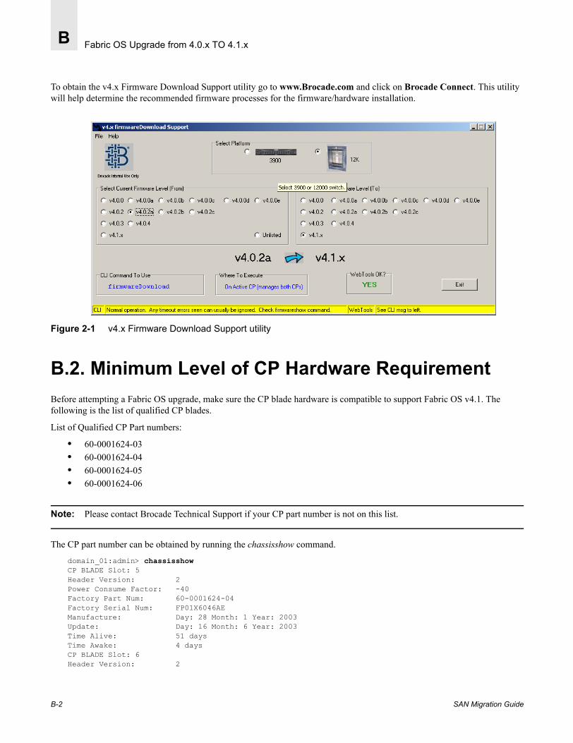
Fabric OS Upgrade from 4.0.x TO 4.1.xB
To obtain the v4.x Firmware Download Support utility go to www.Brocade.com and click on Brocade Connect. This utility will help determine the recommended firmware processes for the firmware/hardware installation.
Figure 2-1 v4.x Firmware Download Support utility
B.2. Minimum Level of CP Hardware RequirementBefore attempting a Fabric OS upgrade, make sure the CP blade hardware is compatible to support Fabric OS v4.1. The following is the list of qualified CP blades.
List of Qualified CP Part numbers:
• 60-0001624-03• 60-0001624-04• 60-0001624-05• 60-0001624-06
Note: Please contact Brocade Technical Support if your CP part number is not on this list.
The CP part number can be obtained by running the chassisshow command.
domain_01:admin> chassisshowCP BLADE Slot: 5Header Version: 2Power Consume Factor: -40Factory Part Num: 60-0001624-04Factory Serial Num: FP01X6046AEManufacture: Day: 28 Month: 1 Year: 2003Update: Day: 16 Month: 6 Year: 2003Time Alive: 51 daysTime Awake: 4 daysCP BLADE Slot: 6Header Version: 2
B-2 SAN Migration Guide

Fabric OS Upgrade from 4.0.x TO 4.1.x B
Power Consume Factor: -40Factory Part Num: 60-0001624-04Factory Serial Num: FP01X60469AManufacture: Day: 28 Month: 1 Year: 2003Update: Day: 16 Month: 6 Year: 2003Time Alive: 51 days
Verifying Compaq Flash-256 MB domain_01:root> df -lk (shows two partitions of approximately 120 MB each)Filesystem 1k-blocks Used Available Use% Mounted on/dev/root 120112 * 54692 65420 46% / * 2 partition of 128MB each/dev/hda2 120128 * 51520 68608 43% /mnt
B.3. Downloading Fabric OSFabric OS is available on the Brocade Connect and Brocade Partner Network web sites, and can be easily downloaded to a local server directory where it can be accessed from the switch during upgrade process.
1. Connect to the Brocade web site www.brocade.com and select Support login from the Services and Support list. For OEM specific downloads, click the Partner Network link in the upper right corner of the screen.
2. Log in providing your User ID and Password.3. Select Direct Support Users link.4. Select Downloads link from left column.5. Select Downloads from the list under Technical Resource Center.6. Select the Firmware link.7. Click the v 4.1.x Firmware link.8. Before downloading you are requested to provide the necessary information.
Note: The information must be completed for each customer installation.
9. Read the End user software license agreement screen read and click ACCEPT to proceed.10. Select the appropriate file from the list of Firmware and related files.11. Unzip the v4.1.0 file into a directory where it can be accessed from a SilkWorm Telnet session.
SAN Migration Guide B-3

Fabric OS Upgrade from 4.0.x TO 4.1.xB
B.4. Fabric OS Downloading Procedure on the SilkWorm 12000To initiate the firmware download use the firmwaredownload command without specifying any options. Based on the current version of firmware, the user must determine on which CP to initiate the firmwaredownload command.
Note: A firmwaredownload -s command option lets you control the process steps interactively. For example you can delay firmware commitment until you are satisfied with the functionality of the new firmware. Since one partition always keep a copy of the older version until the new firmware is committed, it can easily revert back to the previous version.
A step by step manual procedure is described for the purpose of understanding the download process, however the recommended command line method which does not require intervention is shown in Example-5B (page B-9).
B.4.1. Upgrading to Fabric OS 4.1.0 from Fabric OS 4.0.0c or Lower1. Download the firmware from the Brocade Connect web site and place in a directory on your local server where the file
can be easily accessible. (See Downloading Fabric OS on page B-3.)
2. Open a telnet session on the logical switch in the chassis that needs to be upgraded and verify the current Fabric OS version running with either the version command or the firmwareshow command.Fabric OS (cp0)cp0 login: adminPassword:Please change your passwords now.Use Control-C to exit or press 'Enter' key to proceed.
domain_01:admin> versionKernel: 2.4.2Fabric OS: v4.0.0cMade on: Mon Jun 14 17:20:34 2002Flash: Tue Jun 17 15:11:06 2003BootProm: 3.1.18domain_01:admin> firmwareshow Local CP (Slot 5, CP0): Active Primary partition: v4.0.0c Secondary Partition: v4.0.0c Remote CP (Slot 6, CP1): Standby Primary partition: v4.0.0c Secondary Partition: v4.0.0c
3. Determine the CP blade Slot 5 and 6 compatibility by Brocade Part number (See Minimum Level of CP Hardware Requirement on page B-2) CP Blade P/N 60-0001624-04 is on the eligibility list.domain_01:admin> chassisshow
CP BLADE Slot: 5Header Version: 2Power Consume Factor: -40Brocade Part Num: 60-0001624-04Brocade Serial Num: FP01X6046AEManufacture: Day: 28 Month: 1 Year: 2003Update: Day: 16 Month: 6 Year: 2003
B-4 SAN Migration Guide

Fabric OS Upgrade from 4.0.x TO 4.1.x B
Time Alive: 51 daysTime Awake: 0 days
CP BLADE Slot: 6Header Version: 2Power Consume Factor: -40Brocade Part Num: 60-0001624-04Brocade Serial Num: FP01X60469AManufacture: Day: 28 Month: 1 Year: 2003Update: Day: 16 Month: 6 Year: 2003Time Alive: 51 daysTime Awake: 0 days
4. (Optional) Save the current switch configuration by executing the configupload command.
It is always a good practice to save the existing switch configuration on a server prior to initiating an upgrade or downgrade process. A successful download process preserves the existing switch configuration parameters. This file can be used either to verify the post download switch configuration or restore the switch configuration by using the complementary configdownload command.
domain_01:admin> configuploadServer Name or IP Address [host]: 192.168.162.204User Name [user]: rootFile Name [config.txt]: domian01.txtPassword:Upload complete
5. Determine the IP address for Switch and CP blades.domain_01:admin> ipaddrshow 4
SWITCH0Ethernet IP Address: 192.168.173.178Ethernet Subnetmask: 255.255.255.0Fibre Channel IP Address: 0.0.0.0Fibre Channel Subnetmask: 0.0.0.0
SWITCH1Ethernet IP Address: 192.168.173.179Ethernet Subnetmask: 255.255.255.0Fibre Channel IP Address: 0.0.0.0Fibre Channel Subnetmask: 0.0.0.0
CP0Ethernet IP Address: 192.168.173.180Ethernet Subnetmask: 255.255.255.0HostName: cp0Gateway Address: 192.168.173.1
CP1Ethernet IP Address: 192.168.173.181Ethernet Subnetmask: 255.255.255.0HostName: cp1Gateway Address: 192.168.173.1
Backplane IP address of CP0: 10.0.0.5Backplane IP address of CP1: 10.0.0.6
6. The recommended procedure is to download firmware on the Standby CP for minimum fabric interruption when using v4.0.0c or lower. Determine the Standby CP from the output of the hashow command.domain_01:admin> hashowLocal CP (Slot 5, CP0): ActiveRemote CP (Slot 6, CP1): Standby, HealthyHA enabled, Heartbeat Up,
SAN Migration Guide B-5

Fabric OS Upgrade from 4.0.x TO 4.1.xB
7. Log in to the Standby CP (Standby CP1 slot #6 and IP address=192.168.173.181) and verify the exiting Fabric OS version by executing firmwareshow command.
8. Execute firmwaredownload option. In this case on standby CP1.
domain_01:admin> firmwaredownload
Server Name or IP Address: 192.168.163.32 [Server IP address where firmware file resides]User Name: root [User login to server]File Name: /fw/v4.1.0/release.plist [Directory path on server]Password:Full Install (Otherwise upgrade only) [Y]: Y (Always answer “Y”)Do Auto-Commit after Reboot [Y]: NReboot system after download [N]: NFirmwareDownload has started.Removing obsolete packages...Removing hex-1.2-1Removing tcpdump-3.6.2-1Start to install packages......dir ##################################################setup warning: /etc/passwd created as /etc/passwd.rpmnewwarning: /etc/passwd.upgrade created as /etc/passwd.upgrade.rpmnew##################################################
Output has been truncated for clarity....Write kernel image into flash..............Verification SUCCEEDEDFirmwaredownload completes successfully.FirmwareDownload has completed successfully.
Note: The release.plist file is not located in the root of the firmware directory (/fw/v4.1.0), but the firmware download process will automatically use the appropriate release.plist file in the child directory, based on the switch type (i.e. 3900, 12000, etc).
9. Once firmwaredownload has been successfully completed, use the reboot command to reboot the standby CP.10. Log in to the active logical switch again (in this case IP=192.168.173.178) and verify the firmware has been installed with
the firmwareshow command.
domain_01:admin> firmwareshowLocal CP (Slot 5, CP0): ActivePrimary partition: v4.0.0cSecondary Partition: v4.0.0cRemote CP (Slot 6, CP1): StandbyPrimary partition: v4.1.0Secondary Partition: v4.0.0c
11. Verify the CPs are redundant with the haShow command.domain_01:admin> hashowLocal CP (Slot 5, CP0): ActiveRemote CP (Slot 6, CP1): StandbyHA Enabled, Heartbeat Up
12. Execute the hafailover command to failover the active CP0 to standby CP1 in order to perform firmwaredownload on the second CP0:domain_01:admin> hafailover
Warning: This command is being run on a control processor(CP)
B-6 SAN Migration Guide

Fabric OS Upgrade from 4.0.x TO 4.1.x B
based system and will cause the active CP to reset. This willcause disruption to devices attached to both switch 0 and switch 1and will require that existing telnet sessions be restarted.To just reboot a logical switch on this system, use commandswitchreboot(1M) on the logical switch you intend to reboot.
Are you sure you want to reboot the active CP [y/n]? YForcing Failover...done
13. Wait three minutes to allow both CPs to come online and synchronize then verify via hashow.domain_01:admin> hashowLocal CP (Slot 6, CP1): ActiveRemote CP (Slot 5, CP0): Standby, Healthy (IP=192.168.173.180)HA enabled, Heartbeat Up, HA State synchronized
14. After hafailover, CP1 becomes Active CP and CP0 becomes Standby. Obtain the IP address of the new standby CP0 from output of step 5. Open a telnet session to 192.168.162.180 (Standby CP0, Slot 5) and log in to the new standby CP0. Repeat step 8 to upgrade firmware on second CP.domain_01:admin> firmwaredownloadServer Name or IP Address: 192.168.163.32User Name: rootFile Name: /fw/v4.1.0/release.plistPassword:Full Install (Otherwise upgrade only) [Y]: Y (Always answer “Y”)Do Auto-Commit after Reboot [Y]: NReboot system after download [N]: NFirmwareDownload has started.Removing obsolete packages...Write kernel image into flash.…………………………………Output truncated………….Verification SUCCEEDEDFirmwaredownload completes successfully.FirmwareDownload has completed successfully.
15. Once firmwaredownload has been successfully completed, use the reboot command to reboot the standby CP.16. Wait three minutes to allow both CPs to come online and synchronize. Then log in to an active logical switch again (in this
case 192.168.173.178) and verify both primary partitions have Fabric OS v4.1.0 loaded, and both secondary partitions have the original V4.0.0c firmware loaded:
domain_01:admin> hashowLocal CP (Slot 6, CP1): ActiveRemote CP (Slot 5, CP0): Standby, HealthyHA enabled, Heartbeat Up, HA State synchronized
domain_01:admin> versionKernel: 2.4.19Fabric OS: v4.1.0Made on: Thu May 1 18:43:13 2003Flash: Tue Jun 17 16:41:53 2003BootProm: 3.2.4
domain_01:admin> firmwareshowLocal CP (Slot 6, CP1): ActivePrimary partition: v4.1.0Secondary Partition: v4.0.0cRemote CP (Slot 5, CP0): StandbyPrimary partition: v4.1.0Secondary Partition: v4.0.0c
SAN Migration Guide B-7

Fabric OS Upgrade from 4.0.x TO 4.1.xB
17. At this point both CPs are running Fabric OS version 4.1.0. After verifying switch functionality under Fabric OS v4.1.0, continue the process.
18. Log in to each CP (both the active and the standby) and execute the firmwarecommit command to copy the Fabric OS v4.1.0 firmware to the secondary partition (writing over the Fabric OS v4.0.0c version). You DO NOT need to execute hafailover.
cp0 login: adminPassword:****************************************************************************Logging into STANDBY CP, not all commands are fully supported!!******************************************************************************domain_01:admin> firmwarecommitRemoving obsolete packages...Removing hex-1.2-1Removing tcpdump-3.6.2-1Doing firmwarecommit now.Please wait...Replicating kernel image.................Firmwarecommit completes successfully.
cp1 login: adminPassword:
domain_01:admin> firmwarecommitRemoving obsolete packages Removing hex-1.2-1Removing tcpdump-3.6.2-1Doing firmwarecommit now.Please wait...................................................................................Replicating kernel image.................Firmwarecommit completes successfully.
19. Verify all partitions are synchronizeddomain_01:admin> firmwareshowLocal CP (Slot 6, CP1): ActivePrimary partition: v4.1.0 Secondary Partition: v4.1.0Remote CP (Slot 5, CP0): StandbyPrimary partition: v4.1.0Secondary Partition: v4.1.0
Note: If Local CP and Remote CP have different versions of firmware, please retry firmwaredownload command.
B-8 SAN Migration Guide

Fabric OS Upgrade from 4.0.x TO 4.1.x B
B.4.2. Upgrading to Fabric OS 4.1 from Fabric OS 4.0.0d or Greater 1. Determine the current Fabric OS version and current state of Primary and secondary partitions on the Active and Standby
CP by executing the commands: version, hashow, and firmwareshow
domain_01:admin> versionKernel: 2.4.2Fabric OS: v4.0.2aMade on: Mon Oct 14 17:20:34 2002Flash: Wed Jun 18 18:20:38 2003BootProm: 3.1.18domain_01:admin> hashowLocal CP (Slot 5, CP0): ActiveRemote CP (Slot 6, CP1): Standby HA Enabled, Heartbeat Up, HA State synchronizeddomain_01:admin> firmwareshowLocal CP (Slot 5, CP0): Active Primary partition: v4.0.2a Secondary Partition: v4.0.2aRemote CP (Slot 6, CP1): Standby Primary partition: v4.0.2a Secondary Partition: v4.0.2a
2. After verifying the firmware upgrade eligibility for auto-mode, execute the firmwaredownload command on the active CP. domain_01:admin> firmwaredownload
This command will upgrade both CPs in the switch. If youwant to upgrade a single CP only, please use -s option.You can run firmwareDownloadStatus from a telnet sessionto get the status of this command.This command will cause the active CP to reset. This willcause disruption to devices attached to both switch 0 andswitch 1 momentarily and will require that existing telnetsessions be restarted.Do you want to continue [Y]: YServer Name or IP Address: 192.168.163.32User Name: rootFile Name: /fw/v4.1.0/release.plistPassword:FirmwareDownload has started on Standby CP. It may take up to 10 minutes.FirmwareDownload has completed successfully on Standby CP.Standby CP reboots.Standby CP booted up.Standby CP booted up with new firmware.
Note: The release.plist file is not located in the root of the firmware directory (/fw/v4.1.0), but the firmware download process will automatically use the appropriate release.plist file in the child directory, based on the switch type (i.e. 3900, 12000, etc).
3. Monitor the firmware download status from different telnet window:
domain_01:root> firmwaredownloadstatus
[0]: Wed Jun 18 18:46:16 2003cp0: Firmwaredownload has started on Standby CP. It may take up to 10 minutes.[1]: Wed Jun 18 18:51:04 2003cp0: Firmwaredownload has completed successfully on Standby CP.
SAN Migration Guide B-9

Fabric OS Upgrade from 4.0.x TO 4.1.xB
[2]: Wed Jun 18 18:51:07 2003cp0: Standby CP reboots.[3]: Wed Jun 18 18:53:42 2003cp0: Standby CP booted up.[4]: Wed Jun 18 18:53:45 2003cp0: Standby CP booted up with new firmware.[5]: Wed Jun 18 18:56:31 2003cp1: Active CP forced failover succeeded. Now this CP becomes Active.[6]: Wed Jun 18 18:56:35 2003cp1: Firmwaredownload has started on Standby CP. It may take up to 10 minutes.[7]: Wed Jun 18 19:01:37 2003cp1: Firmwaredownload has completed successfully on Standby CP.[8]: Wed Jun 18 19:01:40 2003cp1: Standby CP reboots.[9]: Wed Jun 18 19:04:48 2003cp1: Standby CP booted up with new firmware.[10]: Wed Jun 18 19:04:52 2003cp1: Firmwarecommit has started on both Active and Standby CPs.[11]: Wed Jun 18 19:10:27 2003cp1: Firmwarecommit has completed successfully on Active CP.[12]: Wed Jun 18 19:10:28 2003cp1: Firmwaredownload command has completed successfully.
4. It takes approximately 20-25 minutes total to upgrade both CPs. Upon completion executing the commands: version, hashow and firmwareshow to verify firmware and HA synchronize status.
domain_01:root> versionKernel: 2.4.19Fabric OS: v4.1.0Made on: Thu May 1 18:43:13 2003Flash: Wed Jun 18 18:49:27 2003BootProm: 3.2.4
domain_01:root> hashowLocal CP (Slot 6, CP1): ActiveRemote CP (Slot 5, CP0): Standby, HealthyHA enabled, Heartbeat Up, HA State synchronized
domain_01:root> firmwareshowLocal CP (Slot 6, CP1): Active
Primary partition: v4.1.0Secondary Partition: v4.1.0
Remote CP (Slot 5, CP0): StandbyPrimary partition: v4.1.0Secondary Partition: v4.1.0
Note: If the Local CP and Remote CP have different versions of firmware, please retry the firmwaredownload command.
B-10 SAN Migration Guide

Fabric OS Upgrade from 4.0.x TO 4.1.x B
B.4.2.1. 5C. Firmwaredownload Procedure Using Brocade Web Tools
Note: This procedure is recommended for Fabric OS version 4.0.2 or greater.
1. Open a Web Tools session by providing http address (active switch IP Address) and click Admin view. Find the current Fabric OS version and upgrade eligibility (see Table 2-1 on page B-1).
Figure 2-2 Web Tools Admin View
SAN Migration Guide B-11

Fabric OS Upgrade from 4.0.x TO 4.1.xB
2. Select the Firmware Download button from Upload/Download tab and enter the User name, password, server IP address, and complete path for Fabric OS v4.1.0 directory appended by the release.plist file.
Figure 2-3 Switch Admin view of Upload/Download Tab
Note: The release.plist file is not located in the root of the firmware directory (/fw/v4.1.0), but the firmware will use the appropriate release.plist file in the child directory, based on its type.
3. After providing the information, click Apply or OK to start the firmware download process. The firmware download process is similar as described in Upgrading to Fabric OS 4.1 from Fabric OS 4.0.0d or Greater on page 9.
4. Monitor the Firmware Download status bar and message window for process updates or error messages, until the firmware download is completed successfully on both CPs.
5. Close the Web Tools session and re-open a new session and verify the new firmware version and switch functionality.
B-12 SAN Migration Guide

Fabric OS Upgrade from 4.0.x TO 4.1.x B
Figure 2-4 Switch View after Firmware Upgrade
6. Click the Info button on each switch to view switch online status. Additional verification can be done from a telnet session as described in Upgrading to Fabric OS 4.1 from Fabric OS 4.0.0d or Greater on page 9.
B.5. Firmware Upgrade on a SilkWorm 3900The SilkWorm 3900 firmware can be upgraded either using Command Line interface (CLI) or Brocade Web Tools exactly the same way as shown above for SilkWorm 12000. Web Tools and Brocade Fabric Manager 4.0.1 support is available for Fabric OS 4.0.2 and later versions.
Table 2-2
Note: The SilkWorm 3900 firmware download procedure is invoked with firmwaredownload command providing reboot and auto-commit capability or using Brocade Fabric Manager and Web Tools GUI interface. The SilkWorm 3900 requires self-rebooting to activate new firmware, therefore the firmware download process in this case is disruptive. (The IO path is restored after self-diagnostic test is completed by the switch following a re-boot).
Version Download Method V4.1 Upgrading process
v4.0.2 or greater
CLI/Web Tools/FM Firmware Download
SAN Migration Guide B-13

Fabric OS Upgrade from 4.0.x TO 4.1.xB
B.6. Verifying Switch Functionality The following commands can be run to verify the functionality of the switch after upgrading to Fabric OS 4.1.0.
1. Log in to the switch via telnet using the Admin account. User login, password parameters must not change.
2. At the command prompt, run the command version. The version should be reported to be Fabric OS V4.1.03. Run the command firmwareshow. Primary and secondary partitions must have the same Fabric OS version v4.1.04. Run the command hashow. This will indicate if the switch has rebooted successfully and has achieved HA state with both
CPs synchronized.5. Run the command configupload.
(A) On the system where the file was sent, compare the zoning configuration in this file to that of the file sent by configupload from before the upgrade. This will ensure the zoning configuration has come through the upgrade without being changed.(B) Compare the Fabric Watch information in this file to that of the file sent by configupload from before the upgrade. This will ensure the Fabric Watch configuration has come through the upgrade without being changed.
6. Run the command hafailover.The hafailover command will initiate a failover from the active CP to the standby CP without disruption to Fibre Channel traffic. No RSCN will be raised during the failover. An SNMP trap will be raised but MIB updates are required before this will be properly recognized.
7. Check that the SNMP functionality is working.Inject an event for which the switch is configured to send an SNMP trap (i.e. disconnect a primary ISL). Verify that this trap was received by the SNMP management workstation.
8. Run the command switchshow.
This will indicate which ports have devices connected and what state each is in. Compare this list to the one in the supportshow taken before the upgrade to be certain all devices are connected to the switch and logged into the fabric.
9. Host to storage connectivityThis can only be accomplished from the host machine. Select a host connected to the fabric and check to ensure that the expected volumes are available.
10. If the firmwaredownload was initiated and completed online with active IO transaction.On a SilkWorm 12000 make sure the IO path(s) remain open and IO is undisturbed.
B-14 SAN Migration Guide

SAN Migration Guide
Appendix
C
GlossaryThe glossary should be modified to include terms that are used in the document. This means terms may have to be deleted and others added.
C.1. Terms and DefinitionsThese terms and definitions are provided to ensure that a consistent language for describing SANs is used throughout the document and so that the reader understands what these terms mean. This section is not intended to be all-inclusive.
Table 3-1 Key Terms and Definitions
Terms Definitions and Impact
“golden” switch configurations
For larger SAN fabrics, or for the staging of many smaller fabrics, use configupload to baseline the “golden” switch. The “golden” switch configuration can be downloaded with Fabric Manager to all others in the fabric. Do baselines by Fabric OS version. In other words, if the fabric contains Fabric OS 3.1 and 4.1 switches create two “golden” switch configurations.
Blocking The inability of one device to connect to another device. The Brocade Virtual Channel implementation of Fibre Channel does not block. The term blocking is often confused with the term congestion.
Congestion If two or more sources contend for the same destination, performance for each source may decrease; however, available bandwidth is shared fairly by all sources contending for the same destination. Congestion is the realization of the potential of over-subscription. Congestion may be due to contention for a shared storage port or host port, or an ISL.
Control Processor The term control processor is associated with a SilkWorm 12000 component/FRU (field replacable unit). The SilkWorm 2000, 3200, 3800, and 3900 switches do not have a FRU specifically associated with it and when CP is used in the context of other SilkWorm switches, the reference is to the switch CPU and not a FRU.
Core PID Format The 24-bit Switch Fabric Port Identification (PID) also known as SID consists of Domain ID, Area and AL_PA fields.
Core Switch Also known as a “core fabric switch.” This is one of the switches at the logical center of a Core/Edge fabric. There are generally at least two core switches per Core/Edge fabric to enable resiliency within the fabric. Ports on a core switch are normally used for ISLs.
C-1

GlossaryC
Edge Switch This is one of the switches on the logical outside edge of a Core/Edge fabric. There are generally many more edge switches than core switches. Ports on edge switches are used for SAN device connections.
Fabric One or more interconnected Fibre Channel switches. The term “Fabric” only refers to the interconnected switches, not to nodes or devices connected to the fabric.
Fabric build(BF)
The build fabric Switch Fabric Internal Link Service requests a non-disruptive configuration to the entire fabric. A BF process shall not cause the Domain ID list to be cleared. This preserves existing node port addresses and allows open exchanges to be completed.
Impact: Fabric build is a non-disruptive process to I/O.
Fabric Port Count The number of ports available to connect SAN devices in a fabric. ISLs ports (E-ports) are not included in this count. (Also known as user port count.)
Fabric Re-Configura-tion (RCF)
Fabric re-configuration is a disruptive fabric operation during which Domain IDs may change. If the Domain ID changes, all attached node ports must re-login with the fabric and be assigned new N-Ports identifiers reflecting the change in Domain IDs.
Impact: Reconfigure causes Class-n frames (1,2,3,4 or 6) to be discarded and class 1 connection to be abnormally removed.
Fabric Segmentation A fabric is unable to resolve the switch configuration parameters during the rebuild process with one or more switches, and may isolate them from the fabric, causing fabric segmentation.
Impact: I/O operations are ceased only on those devices losing their access due to segmentation.
Fabric Topology A topology is “the logical layout of the components of a computer system or network and their interconnections.” A fabric topology is the layout of the switches that form a fabric.
Fan-in The ratio of storage ports to a single host port.
Fan-out The ratio of host ports to a single storage port.
FRU Field Replaceable Unit
FSPF Fabric Shortest Path First protocol. The FSPF protocol was developed by Brocade and subsequently adopted by the Fibre Channel standards community for allowing switches to discover the fabric topology and route frames correctly. It is now the industry standard routing protocol for Fibre Channel networks.
HA High Availability
High Locality If devices that communicate with each other are connected to the same switch or groups of switches then these devices have high locality. The higher the locality, the less traffic crosses ISLs/trunks and therefore, fewer ISLs/trunks are needed.
Hop Count For evaluating SAN designs, the hop count is identical to the number of ISLs that a frame must traverse to reach its destination.
Host Edge Switch Edge switch with host device connections only.
C-2 SAN Migration Guide

Glossary C
Incremental Upgrade Replacing one switch at a time in an online fabric.
ISL Inter-Switch Link. ISLs connect two switches via E-ports.
ISL Over-Subscription Ratio
In networks where all ports operate at the same speed, the over-subscription ratio for an ISL is the number of different ports that could contend for the use of its bandwidth. If there are 14 node ports on a switch and two ISLs, the ratio is 14:2, or 7:1. When there is a mixture of port speeds, the exact calculation is not as simple. The rule of thumb is that the lower the ratio is, the better performance is likely to be.
Latency The time it takes for a frame to traverse from its source to its destination is referred to as the latency of the link. Sometimes a frame is switched from source to destination on a single switch and other times a frames must traverse several hops between switches before it reaches its destination.
Locality The degree that I/O is confined to a particular switch or segment of a fabric. If two devices that need to communicate with each other are located on the same switch or fabric segment, then these two devices are said to have high locality. If these same devices are located on different switches or segments of a fabric and these two devices need to communicate with each other, then these devices are said to have low locality.
Logical Switch The SilkWorm 12000 can contain up to 128 ports in a 14U chassis, configured as two 64-port switches. Each switch is known as a logical switch and may also be referred to as a Domain.
Low Locality If two devices must cross an ISL/Trunk to communicate, then these devices have low locality. The lower the locality, the more traffic crosses ISLs/trunks and therefore, more ISLs/trunks are needed.
NMS Network Management Software
Node Any SAN device – usually either a host or storage device – that attaches to a fabric.
Node Count The number of nodes attached to a fabric.
Octet An octet is a group of two adjacent quads. The SilkWorm 3900 is the only SilkWorm switch that implements octets. Octets are used primarily to define boundaries for performance tuning purposes.
Offline Fabric A non-functional state of fabric unsuitable for I/O operation.
Online Fabric A functional stable state of a fabric performing reliable I/O fabric operations.
Over-Subscription A condition where more nodes could potentially contend for the use of a resource – such as an ISL – than that resource could simultaneously support, that resource is said to be over-subscribed.
PID bindings Static mapping between physical and logical devices on a host accomplished via Port_ID (PID).
Radius The greatest “distance” in hops between any edge switch and the center of a fabric can be thought of at that fabric’s radius. Low radius networks have lower hop counts and latency than high radius fabrics. The unit of measurement for a fabric radius is hops.
SAN Migration Guide C-3

GlossaryC
Redundant Fabric A SAN composed of two or more independent fabrics The multiple fabric architecture makes dual fabric SANs redundant.
Impact: SAN topology configured to provide two or more alternate paths for high availability.
Resilience The ability of a fabric to adapt to or tolerate a failure of a component.
SAN A Storage Area Network (SAN) can consist of one or more related fabrics and the connected SAN devices.
SAN Architecture The overall design or structure of a storage area network solution. This includes one or more related fabrics, each of which has a topology. Other components may also be included, such as host, storage, and other SAN devices.
SAN Port Count The number of ports available for connection by nodes in the entire SAN. The SAN Port Count equals the fabric port count in a single fabric SAN and is equal to the sum of each fabric’s port count in a multi-fabric SAN.
Scalability The ease with which a particular design can grow and adapt without requiring a significant change in SAN architecture or requiring a substantial re-layout of existing SAN devices.
Secure Mode Disabled An operating mode where all switches that participate in the fabric are unable to successfully execute the command secModeEnable or if the command secModeDisable is successfully executed in the fabric.
Secure Mode Enabled An operating mode where all switches that participate in the fabric are running a version of Fabric OS that supports the security feature, have licenses to run security, and the command secModeEnable has been successfully executed.
Single Fabric A SAN composed of a single fabric may be configured to provide one or more paths via different switches of the fabric.
Impact: Offers no Protection at fabric level. All paths are closed when fabric is offline, completely stopping I/Os.
SPOF A single point of failure. A SPOF in a SAN is any component – either hardware or software – that could cause a fabric or a SAN to fail.
Storage Edge Switch Edge switch with storage device connections only.
Tiering The process of grouping particular SAN devices by function and then attaching these devices to particular switches or groups of switches based on that function
Total Ports The total number of ports of all the switches in the SAN
User Ports Total number of switch ports less ports used for ISLs/trunks
WWPN World Wide Port Name
C-4 SAN Migration Guide