san7>--9s-oai 7l 34 no? i-) c
TRANSCRIPT

0
SAN7>--9S-OaI 7 L 34 NO? 8 -b 2 I - ) c.
SAFE EPOXY ENCAPSULANT FOR HIGH
Robert 0. Sanchez (505)844-3 103
FAX (505)844-3888 E-Mail [email protected]
Wendal E. Archer (505)844-66 18
FAX (505)844-3888 E-Mail [email protected]
Passive Devices/Interconnects Department 125 1 P.O. Box 5800, MS0523
Sandia National Laboratories Albuquerque NM 87185,USA
SUMMARY
This paper describes the use of “Formula 456”, an aliphatic amine cured epoxy for impregnating coils and high voltage transformers. Sandia has evaluated a number of MDA-free epoxy encapsulants which relied on either anhydride or other aromatic amine curing agents. The use of aliphatic amine curing agents was more recently evaluated and has resulted in the definition of “Formula 456” resin. Methylene diani (MDA) has been used for more than 20 & ea s the curing agent for various epoxy formulations throughout the Department of Energy and much of industry. Sandia National Laboratories began the process of replacing MDA with other formulations because of regulations imposed by OSHA on the use of MDA. OSHA has regulated MDA because it is a suspect carcinogen. Typically the elimination of OSHA-regulated materials provides a rare opportunity to qualify new formulations in a range of demanding applications. I t was important to take full advantage of that opportunity, although the associated materials qualification effort was costly. Small high voltage transformers are one of those demanding applications. The successful implementation of the new formulation for high reliability transformers will be described. The test results that demonstrate the parts are qualified for use in DOE weapon systems will be presented.
INTRODUCTION
The magnetic components required to support the various Department of Energy and Department of Defense programs include: transformers, solenoid coils, and inductors. A rugged package is essential because of some military type applications where high voltage, size and severe environments are major considerations. For more than 20 years Sandia has used a formula defined in Sandia specification 9927020 for encapsulating and impregnating these type of coils. The formula (from here on will refer to as old formula) consists of an epoxy resin (Epon 828), a hardner (MDA), a filler (normally mica) and some color paste. OSHA has regulated MDA because it is a suspect carcinogen. Formulation development for MDA-free epoxies has targeted not only the replacement of methylene dianiline (MDA), but also the improvement of other formulation properties and processability .
Sandia and the Department Of Energy (DOE) production agencies have evaluated a number of MDA-free epoxy encapsulants which relied on either anhydride or other aromatic amine curing agents. The use of aliphatic amine curing agents was recently evaluated and has resulted in the definition of two promising alternative resins. Both rely on the same Bis A epoxies previously used with MDA and both use the same replacement curing agents; a blend of

DISCLAIMER
This report was prepared as an account of work sponsored by an agency of the United States Government. Neither the United States Government nor any agency thereof, nor any of their employees, makes any warranty, express or implied, or assumes any legal liability or responsibility for the accuracy, completeness, or use- fulness of any information, apparatus, product, or process disclosed, or represents that its use would not infringe privately owned rights. Reference herein to any spe- cific commercial product, process, or service by trade name, trademark, manufac- turer, or otherwise does not necessarily constitute or imply its endorsement, recom- mendation, or favoring by the United States Government or any agency thereof. The views and opinions of authors expressed herein do not necessarily state or reflect those of the United States Government or any agency thereof.

Jeffamine D-230 (a flexible polyether diamine) and Ancamine 2049 (a cycloaliphatic diamine). Formula 456 is a rubber modified formulation which also includes a Dow Bis A epoxy containing 40% by weight of a phase-separated rubber modifier (Dow XU-71790). Formula 459 contains only a unmodified Bis A epoxy and adds a silicone based de-gassing aid. Both formulations are readily processed at temperature below those required for the MDA cured formulations. They possess lower viscosities and also degas very effectively. Electrical and mechanical properties are typically comparable to or better than those of similar MDA cured materials. Formula 456 will be used for our evaluation.
TRANSFORMER DESIGNS
MIL-SPEC MAGNETICS, INC. undertook the task of comparing Formula 456 to the old Epoxy MDA Formulation on the two different transformer designs. A power transformer (see Figure 1) and a current viewing transformer (CVT) (see Figure 3) were selected as the baseline design components used to evaluate this MDA-free encapsulant. Two lots of fifty parts each of the power transformer and three lots of seventy parts each of the CVT were used during the evaluation. Sandia specification SS708389 was followed during encapsulation. The power transformer was of special interest because of the intricate winding and insulation interleaving pattern of its design. The design for the power transformer is described to provide an understanding of the difficulty of impregnating these type of coils. The design uses a Ferrite Pot-Core and has two separate windings on a nylon bobbin. The primary winding consist of 26 turns of 29 gage wire closely wound. The secondary winding consists of 1114 turns of 40 gage wire closely wound. The primary is placed in a single layer and separated from the secondary using Kraft paper insulation (KPI). The secondary is divided into 21 layers, with KPI separating each layer. Several layers of KPI are placed over the last layer. Each layer of winding is centered within the flanges of the bobbin allowing for adequate margin between the winding and the flanges (see cross section Figure 2). The construction of the power transformer consists of placing the coil into a ferrite pot core and coating the core with Phenolic micro balloon filled polysulfide (a stress relief medium Ref. 2). The coated
assembly is then bonded to a diallyl phthalate (DAP) contact pin assembly. The transformer assembly is then installed into an open cylinder mold and encapsulated. The challenge was to ensure that the ecapsulant totally reaches the spaces between each layer of Kraft paper and between the winding wire spaces.
Power Transformer Figure 1
Cross Section Figure 2
The design for the CVT is basically a toroid with 2 windings, a 50 turn sense winding and a one turn drive. The core is a toroid made of ferrite material. The coil is hand wound, mounted on a contact assembly and encapsulated.

. ..
Material
Epoxy Resin Blend
INCHES
Parts Bv Weight
75
1'
Mica Filler
Curing Agent Blend
Current Viewing Transformer Figure 3
65
25
terminated butadiene nitrite rubber) modified Epon 828 epoxy resin, filled with mica and cured with methylene dianiline (a suspect carcinogen). The other half of the transformers were encapsulated with the new Formula 456.
The following covers the procedure used for the encapsulation and impregnation of magnetic devices using Formula 456:
COIL DRYING
a. The coils were dried in a vacuum oven at a temperature of llO"C, and held at this temperature at a maximum pressure of 25mm Hg absolute for 4 hours, after which the vacuum was broken with dry nitrogen.
b. The units were then cooled and stabilized to 54°C and maintained a t this temperature until they were ready for encapsulation. They were stabilized at this temperature in a vacuum oven a t a maximum pressure of 25mm Hg absolute, after which the vacuum was broken with dry nitrogen.
TRANSFORMER APPLICATIONS DRYING OF FILLER
Power Transformer Characteristics The Power transformer is used in a flyback converter to charge a capacitor to 4.2kV (see Figure 4).
*C!!dlk- CAPACITOR
The mica filler was dried by placing the material in a shallow pan, not over two inches in depth, and baked for four hours minimum in a forced convection oven at a temperature of 107°C.
FORMULATION
1 T
Figure 4
CVT Characteristics Turns/ratio .02 L-inductance .48 to 1.4mH for sense coil
The output of the sense coil is proportional to the current applied to the drive coil, Le., the transformer is basically a current sensing device used for monitoring current pulses in an advanced weapon system.
ENCAPSULATION
Half the transformers were encapsulated with the old epoxy formulation a CTBN (carboxyl
I Color Paste 1 1
Tolerances on weights of materials were held within 1%.
MEING
The preferred batch size is 166 grams combined weight. The maximum batch size recommended is 700 grams. Materials must be homogenous.
a. The epoxy resin, filler and color paste were combined. The material was mixed until uniform throughout.
b. The mixture was stabilized to 54°C when the room temperature curing agent was added. The material was mixed until uniform throughout.
c. Immediately after mixing, the units were evacuated at a pressure of 0.5 to 3.0mm Hg absolute and a temperature of 74°C for 2 minutes after the initial foam rise collapsed.
POURING UNDER V A C W
a. The preheated molds with components were placed in a vacuum chamber and evacuated at a pressure of 0.5 to 3mm Hg absolute.
b. The deaerated mixture temperature was maintained between 45°C to 60°C and immediately poured into the molds under vacuum. The pressure was decreased to 0.5 to 3.0mm Hg for a minimum of three minutes after pouring the last unit. It is important to break the vacuum slowly, 3 minutes minimum, to eliminate voids.
CURE
The compound was then cured in a pressure chamber at 80 PSI for 4 hours @ 25"C, plus 6 hours @ 60"C, plus 12 hours @ 93°C. At the end of cure, the chamber was turned off and parts were allowed to cool in the chamber for 30 minutes.
THERMAL CYCLE AND T E S T
The transformers were subjected to 5 four-hour thermal cycles prior to inspection and test which helps in relieving internal stresses. The temperature extremes for each cycle are -60°C to +93"C, and each cycle requires one hour exposure at each of these temperatures. Each transformer is visually inspected, then electrically tested. The electrical tests consist of DC resistance, inductance, capacitance, turns ratio, polarity, insulation resistance and in addition for the power transformer, an induced voltage (corona test).
ENVIRONMENTAL T E S T
The transformers were subjected to the following environments: 3500G mechanical shock; sinusoidal vibration - frequency range (Hz) 10-2000-10; random vibration - complex power spectral density from 5 Hz to 2000 Hz at .001 G2/Hz to .4G2 /Hz; steady state acceleration lOOG for 10 seconds; temperature shock - 3 cycles -55°C to +lOO"C; and temperature cycle - 150 cycles -55°C to +93"C.
The mica-filled epoxy resin system must provide a rugged system that is capable of surviving high levels of shock and vibration, while having stable characteristics over a 25- year period.
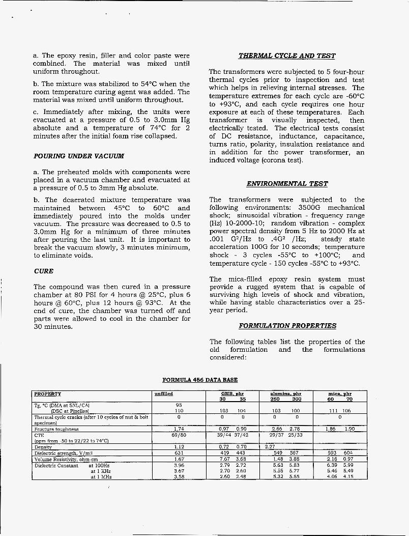
FORMULATION PROPERTIES
The following tables list the properties of the old formulation and the formulations considered:
FORlVLULA 456 DATA BASE

PROPERTY
Dissipation Factor at 100 Hz at 1 KHz at 1 MHZ
Pulse Dielectric at -54°C Strength, at 25°C KV/mil/Bkdn at 71°C Tensile strength, psi maximum
at break Tensile modulus, Ksi Elongation a t max load
at break Butt tensile adhesive strength:
ceramic substrate - initial after 100 TCs
A12024 substrate - initial after 100 TCs
A17075 substrate - initial after 100 TCs
Lap shear adhesive strength, Al/Al (Al2024)
unfilled GMB, phr 30 35
,009 ,050 ,057 ,009 ,036 ,014
alumina, phr mica, phr 60 70 250 300
,021 ,020 ,051 .052 ,022 .019 ,059 .Ob2
,032 ,021 .018 ,019 .018 .041 .043
_ _ -_
1513
11.69 2.69 2.38 4.58 4.27 4.89
FORMULATION 456,459 AND "2" COMPARISON
8.92 9.53 8900 8550 360
9.6%
MDA 12) Formulation
2.36 na 4.48 na 3.46 3.96 3.98 4.06 4.01 3.86 2.25 1.83
5128 10,100 7235
424 2200 751 10,100
1.3% 1.1% 1.5%
toughened Composition: 20 Shell Z
995 4174? 5151?
100 Epon 828- CTBN
(X8 at 10 wt. YO)
1186 818
Rubber modifier content 8.3 wt percent m r a n c e , unfded yellow, cloudy Z ( D M A , storage mod.) 98°C
(DSC) 1.11 W o x v stoichiometry
CTE (-50°-22'/220-500C~
modulus
(250 phr) 10,700
2230 Ksi 0.5%
_ _ (300 phr Alox)
10,100 psi 10,100 psi 2200 Ksi
1.1%
115 cps 17 min. 36 min.
Formula 459
.2.5 Jeffamine D-230
12.5 Ancamine 2049
'5.0 Shell Epon 826
none yellow, clear
95- 100°C
51/56 ppm 19/25
(360 phr)
6 0
11,490 10,380 487 Ksi
5.0%
(300 phr Alox) 10,840 psi 10,840 psi 2870 Ksi
0.6% 0.6%
67 cps 19 min. 42 min.

PROVE-IN TEST RESULTS
Both the power transformer and the current viewing transformer designs were encapsulated using both the old formulation and the new "Formula 456". The results for "Formula 456" are an excellent impregnation of both transformer types. Both transformer designs survived the environmental tests. There was no evidence of any damage observed during visual inspection. There were no significant changes in any electrical parameter. The CVT was qualified for the DOE'S war reserve production. Sandia developed the new material because it does not outgas carcinogenic fumes in the processing stage of encapsulation, as does the old formulation. The criteria for successful substitution (qualification) is for the transformers to have equal or better performance with the new material. Performance evaluation includes electrical and mechanical. The electrical performance was a set of measurements performed on the part to meet subsystems requirements. Mechanical performance criteria was no cracking after the environmental tests. In order to prove-in the new encapsulation material, parts were made at three stages of development, prototype, production prove-in and qualification sample (QS). Mil-Spec Magnetics Inc. made parts with both formulations and performed extensive stress tests for performance comparisons. The environmental stresses were temperatures cycles of 50, 100 and 150 cycles, from -55°C to +93"C. The tests prescribed by the product specification, PS704103, fall into two categories, functional tests and destructive test (D-tests). The D-tests, shock and vibration, and pulse testing were added to meet requirements for a new application.
TEST DATA
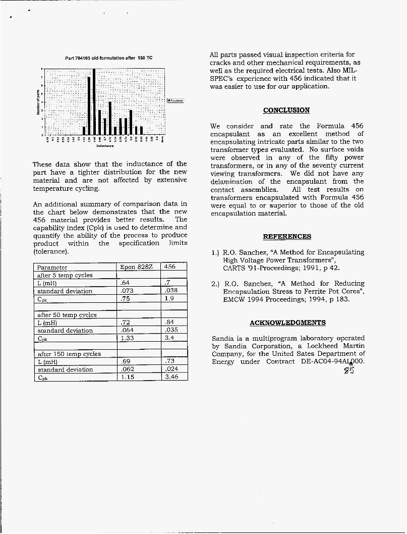
The following data is for the QS parts. Thirty five parts with each formulation were built and compared. The inductance data are shown for comparison purposes. The inductance requirement is for L > .48mH and < 1.4mH. All inductance values are in mH. The following histogram shows the inductance data before temperature cycles for Formula 456:
Part 704103 with Formula 456 before TC
The following histogram shows the inductance data after temperature cycles for Formula 456:
Part 704103 with Formula 456 af&er 150 cycles
14
12
10
i n j 6 0
1
2
0
Inductance
The following histogram shows the inductance data before temperature cycles for the old formulation:
Part704103 old formulation before TC
Inductance
The following histogram shows the inductance data after temperature cycles for the old formulation material:
c
after 50 temp cycles L (mH) s tandard deviation Cpk
Part 704103 old formulation after 150 TC
.72 .84
.064 .035 1.33 3.4
Inductance
These data show that the inductance of the part have a tighter distribution for the new material and are not affected by extensive temperature cycling.
An additional summary of comparison data in the chart below demonstrates that the new 456 material provides better results. The capability index (Cpk) is used to determine and quantify the ability of the process to produce product within the specification limits (tolerance).
Parameter
s tandard deviation
s tandard deviation 3.46
All parts passed visual inspection criteria for cracks and other mechanical requirements, as well as the required electrical tests. Also MIL- SPEC’S experience with 456 indicated that it was easier to use for our application.
CONCLUSION
We consider and rate the Formula 456 encapsulant as an excellent method of encapsulating intricate parts similar to the two transformer types evaluated. No surface voids were observed in any of the fifty power transformers, or in any of the seventy current viewing transformers. We did not have any delamination of the encapsulant from the contact assemblies. All test results on transformers encapsulated with Formula 456 were equal to or superior to those of the old encapsulation material.
REFERENCES
1.) R.O. Sanchez, “A Method for Encapsulating High Voltage Power Transformers”, CARTS ’9 1-Proceedings; 199 1, p 42.
2.) R.O. Sanchez, “A Method for Reducing Encapsulation Stress to Ferrite Pot Cores”, EMCW 1994 Proceedings; 1994, p 183.
ACKNOWLEDGMENTS
Sandia is a multiprogram laboratory operated by Sandia Corporation, a Lockheed Martin Company, for the United Sates Department of Energy under Contract DE-AC04-94ASIQ00.
$5

M98002729 I llllllll Ill 11111 11111 lllll IIIIIIIIIIllI1IIIIllIIIIIllI
1q9k 0 i I = .
'ubi. Date (11)
sponsor Code (18) h6E / h ’ P x #
J C Category (1 9) u e- 7(38
DOE