sand92-7340 uc-721 · pdf fileuc-721 microfiche seal design ... 2-14 liner loading as affected...
TRANSCRIPT
CONTRACTOR REPORT
SAND92-7340Unlimited ReleaseUC-721
MICROFICHE
Seal Design Alternatives Study
L. L. Van SambeekRE / SPEC Inc.Rapid City, SO 57709-0725
O. O. Luo, M. S. Lin, W. Ostrowski, O. OyenugaParsons Brinckerhoff Quade & Douglas, Inc.San Francisco, CA 94107-1317
Prepared by Sandia National Laboratories Albuquerque, New Mexico 87185and Livermore. California 94550 for the United States Department of Energyunder Contract DE-AC04-76DP00789
Printed June 1993
SAHDIA HATIOHALLABORATORIES
TECHHICAL LIBRARV

Issued by Sandia National Laboratories, operated for the United StatesDepartment of Energy by Sandia Corporation.NOTICE: This report was prepared as an account of work sponsored by anagency of the United States Government. Neither the United States Government nor any agency thereof, nor any of their employees, nor any of theircontractors, subcontractors, or their employees, makes any warranty, expressor implied, or assumes any legal liability or responsibility for the accuracy,completeness, or usefulness of any information, apparatus, product, orprocess disclosed, or represents that its use would not infringe privatelyowned rights. Reference herein to any specific commercial product, process, orservice by trade name, trademark, manufacturer, or otherwise, does notnecessarily constitute or imply its endorsement, recommendation, or favoringby the United States Government, any agency thereof or any of theircontractors or subcontractors. The views and opinions expressed herein donot necessarily state or reflect those of the United States Government, anyagency thereof or any of their contractors.
Printed in the United States of America. This report has been reproduceddirectly from the best available copy.
Available to DOE and DOE contractors fromOffice of Scientific and Technical InformationPO Box 62Oak Ridge, TN 37831
Prices available from (615) 576-8401, FTS 626-8401
Available to the public fromNational Technical Information ServiceUS Department of Commerce5285 Port Royal RdSpringfield, VA 22161
NTIS price codesPrinted copy: A016Microfiche copy: AOI

SAND92-7340Unlimited ReleasePrinted April 1993
Seal Design Alternatives Study·
L.L. Van SambeekRE/SPEC Inc.
Rapid City, SD 57709-0725
D. D. Luo, M.S. Lin, W. Ostrowski, D. OyenugaParsons Brinckerhoff Quade & Douglas, Inc.
San Francisco, CA 94107-1317
ABSTRACT
DistributionCategory UC-721
This report presents the results from a study of various sealing alternatives for the WIPPsealing system. Overall, the sealing system has the purpose of reducing to the extentpossible the potential for fluids (either gas or liquid) from entering or leaving the repository.The sealing system is divided into three subsystems: drift and panel seals within therepository horizon, shaft seals in each of the four shafts, and borehole seals.
Alternatives to the baseline configuration for the WIPP seal system design includedevaluating different geometries and schedules for seal component installations and the useof different materials for seal components. Order-of-magnitude costs for the variousalternatives were prepared as part of the study. Firm recommendations are not presented,but the advantages and disadvantages of the alternatives are discussed. Technicalinformation deficiencies are identified and studies are outlined which can provide requiredinformation.
* The content of this report was effective as of January 1993. This report was preparedby RE/SPEC Inc. under Contract 69-5174 with Sandia National Laboratories.

ACKNOWLEDGMENT
The authors gratefully acknowledge the Sandia National Laboratories' technical reviewers.
The review comments by Dr. Frank D. Hansen, Dr. Joe R. Tillerson, and Dr. Rudy Matalucci
provided insight and guidance for the final version.
11

FOREWORD
This report was prepared by a joint effort between Parsons Brinckerhoff Quade & Douglas,
Inc. and RE/SPEC Inc. for Sandia National Laboratories under Contract 69-5174 and meets the
requirements for quality assurance as described in NQA-l.
III

CONTENTS
1.0 INTRODUCTION 1
1.1 Seal Requirements . . . . . . . . . . . . . . . . . . . . . . . . . . . . . . . . . . .. 31.2 Purpose of the Alternatives Study 31.3 Report Organization . . . . . . . . . . . . . . . . . . . . . . . . . . . . . . . . . " 4
2.0 ROCK MECHANICS 5
2.1 Crushed Salt Consolidation 6
2.1.1 Shaft Closure 72.1.2 Drift Closure " . . . . . . . . . . . . . . . . . . . . . . . . . . . . . . . .. 82.1.3 Closure Between Rigid Structures . . . . . . . . . . . . . . . . . . . . . .. 10
2.2 DRZ Around Openings. . . . . . . . . . . . . . . . . . . . . . . . . . . . . . . .. 15
2.2.1 Types of DRZ 152.2.2 Opening-Shape Effects 182.2.3 Stratigraphical Influences . . . . . . . . . . . . . . . . . . . . . . . . . . .. 30
2.3 Loading on Rigid Structures Emplaced in Salt 31
2.3.1 Schedule Effects on Loading Magnitude 312.3.2 Geometrical Effects on Loading Distribution 32
3.0 DRIFT AND PANEL SEALS 35
3. 1 Purpose of the Drift and Panel Seals 363.2 Requirements 36
3.2.1 Reference Seal System 363.2.2 Considerations for Design Alternatives 39
3.3 Assumptions 393.4 Evaluation Criteria 413.5 Seal Design Types . . . . . . . . . . . . . . . . . . . . . . . . . . . . . . . . . . .. 41
3.5.1 Type 1 - NRxx Seal . . . . . . . . . . . . . . . . . . . . . . . . . . . . .. 433.5.2 Type 2 - LGxx Seal 493.5.3 Type 3 - LExx Seal 503.5.4 Type 4 - NR/LEI4 Seal 50
3.6 Evaluation and Selection of Design Types 52
IV
CONTENTS (Continued)
3.6.1 Evaluation of Design Types 523.6.2 Seal Type Selection and Combination 58
3.7 Conclusion 63
4.0 SHAFT SEALS 65
4.1 Purpose 654.2 Requirements for the Shaft Seals 66
4.2.1 Lower Shaft Seals 674.2.2 Upper-Shaft Seals 694.2.3 Water-Bearing Zone Seals 704.2.4 Near-Surface Shaft Seals . . . . . . . . . . . . . . . . . . . . . . . . . . .. 70
4.3 Reference Design/Materials 71
4.3.1 Bentonite 714.3.2 Crushed Salt 754.3.3 Compressed-Salt Blocks 764.3.4 Concrete . . . . . . . . . . . . . . . . . . . . . . . . . . . . . . . . . . . . .. 774.3.5 Alternative Seal Materials 79
4.4 Description of Seal Design Alternatives . . . . . . . . . . . . . . . . . . . . . .. 85
4.4.1 Lower-Shaft Sealing Subsystem 864.4.2 Upper-Shaft Sealing Subsystem 894.4.3 Water-Bearing Zone Sealing Subsystem 934.4.4 Near-Surface Shaft Sealing Subsystem . . . . . . . . . . . . . . . . . . .. 94
4.5 Evaluation of Alternatives 95
4.5.1 Cost Evaluation 954.5.2 Material Performance Evaluation 96
4.6 Conclusion and Recommendations 97
5.0 BOREHOLE SEALS 101
5.1 Purpose 1015.2 Requirements for the Borehole Seals 1035.3 Boreholes Requiring Sealing 105
v
CONTENTS (Continued)
5.4 Borehole Sealing Strategy5.5 Evaluation Considerations
106107
5.5.1 Seal Effectiveness 1075.5.2 Emplacement Techniques 108
5.6 Description of Alternatives 108
5.6.1 Definition 1095.6.2 Emplacement Considerations and Constructibility 110
5.7 Evaluation of Alternatives 119
5.7.1 Seal Effectiveness 1195.7.2 Emplacement Techniques 1215.7.3 Cost 122
5.8 Discussions and Conclusions 123
5.8.1 Discussions5.8.2 Conclusion
6.0 FUTURE WORK
123124
127
7.0 REFERENCES 131
APPENDIX A A-I
APPENDIX B B-1
APPENDIX C C-l
APPENDIX D D-I
vi

Figures
Figure
2-1 Volumetric strain for six depths from the surface in 50-year-old shaft . . . . . 92-2 Volumetric closure for two rectangular-shaped drifts 112-3 Geometries for a lW rigid sleeve and 2W, 3W, and 4W salt-filled region lengths 132-4 Excavation and emplacement sequence for rigid sleeve and salt fill . . . . . . . . .. 142-5 Volumetric strain at the center of the region between the rigid sleeves 162-6 DRZ in salt around a 14- x 12-foot excavation immediately after excavation 212-7 DRZ in salt around a 14- x 12-foot excavation after 1 year . . . . . . . . . . . . .. 222-8 DRZ in salt around a 14- x 12-foot excavation after 40 years. . . . . . . . . . . .. 232-9 DRZ in salt around a 25- x 12-foot excavation immediately after excavation 252-10 DRZ in salt around a 25- x l2-foot excavation after 1 year . . . . . .. 262-11 DRZ in salt around a 25- x 12-foot excavation after 40 years. . . . . . . . . . . .. 272-12 Vertical uplift of MB139 below a 14- x 12-foot excavation . 282-13 Vertical uplift of MB139 below a 25- x 12-foot excavation . 292-14 Liner loading as affected by delayed liner installation 33
3-1 Reference drift and panel seals, plan, elevation, and section 373-2 Drift and panel seals location plan 383-3 Types of seals, base case, and alternative case 423-4 Construction sequence for a rigid sleeve ring segment . . . . . .. 443-5 Rigid sleeve demolition sequence 453-6 Cast-in-place monolith in a rigid sleeve or grouting sleeve 473-7 Construction scheme for long-term salt seal 483-8 DRZ excavation concept for salt seal . , 51
4-1
5-15-25-35-45-55-65-7
Schematic location of shaft sealing subsystems ..
Approximate locations of boreholes in relation to the WIPP undergroundEmplacement methods borehole cleaning and condition .Perforation of borehole casing .Removal of casing .Emplacement of cementitious grout mix .Emplacement of asphalt injection .Emplacement and compaction of crushed salt/bentonite-salt mix ..
Vll
68
104112112113115117118

1-1 Sealing Subsystem Functions
Tables
2
3-1 Order-of-Magnitude Unit Cost Estimates for Base Case and Alternative Case SealTypes. . . . . . . . . . . . . . . . . . . . . . . . . . . . . . . . . . . . . . . . . . . . . .. 53
3-2 Drift and Panel Seals Now Versus Later Considerations 543-3 Drift and Panel Seal Combination 613-4 Summary of Rough Order-of-Magnitude Cost Evaluation 62
4-1 Brine Pressures at Various Depths in Shafts 744-2 Dow Chemical Seal Ring Installation Locations and Hydraulic Pressure Resisted . 794-3 Properties of Dowell Chemical Seal Ring Formulations . . . . . . . . . . . . . . . .. 834-4 Brine and Rock Pressures Against Seals in the Upper-Shaft Seal System 92
5-1 Borehole Sealing Subsystem 1025-2 Order-of-Magnitude Cost Estimate (X $1.0 M) Summary of Total Capital Cost for
Borehole Seal Alternatives 1225-3 Summary of Comparisons of Alternatives 125
A-I Order-of-Magnitude Cost Estimate, Type 1 "NOW RIGID" Rigid Sleeve SealsNRI2, NRI4, and NR20 A-2
A-2 Order-of-Magnitude Cost Estimate, Type 2 "LATER GROUT" Grouting SleeveSeals LGI2, LGI4, LGI8, LG20, and LG25 A-3
A-3 Order-of-Magnitude Cost Estimate, Type 3 "LATER EXCAVATE" OverexcavationSeals LEI2, LEI4, LEI8, LE20, and LE25 A-5
A-4 Order-of-Magnitude Cost Estimate, Type 4 Rigid Sleeve/Overexcavation SealsNR/LE14 A-7
A-5 Rough Order-of-Magnitude Cost Evaluation of Combination 1 A-8A-6 Rough Order-of-Magnitude Cost Evaluation of Combination lA A-9A-7 Rough Order-of-Magnitude Cost Evaluation of Combination 2 . . . . . . . . . . . . A-lOA-8 Rough Order-of-Magnitude Cost Evaluation of Combination 2A A-IIA-9 Rough Order-of-Magnitude Cost Evaluation of Combination 3 A-12A-lO Rough Order-of-Magnitude Cost Evaluation of Combination 3A A-13A-II Rough Order-of-Magnitude Cost Evaluation of Combination 4 A-14
B-1 Bentonite Layer Seal and Emplaced Salt Seal Order-of-Magnitude Capital CostEstimate for Four WIPP Shafts B-2
B-2 Bentonite Ring Seal and Emplaced Salt Seal Order-of-Magnitude Capital CostEstimate for Four WIPP Shafts B-3
B-3 Chemical Seal Ring and Emplaced Salt Seal Order-of-Magnitude Capital CostEstimate for Four WIPP Shafts B-4
viii

B-4 Asphalt Column and Emplaced Salt Seal Order-of-Magnitude Capital Cost Estimatefor Four WIPP Shafts B-5
C-l WIPP Conceptual Seal Design Alternative Study, Borehole Sealing Unit Costs .. C-2C-2 WIPP Conceptual Seal Design Alternative Study, Borehole Sealing Alternative Cost
Estimate C-3
Sketches
Sketch
SK-lSK-2SK-3SK-4
SK-5SK-6SK-7SK-8SK-9SK-lOSK-llSK-12SK-13
Drift and Panel Seals Type 1 - NR 12 Seal, B-3B-B Rigid Sleeve D-2Drift and Panel Seals Type 1 - NR 14 Seal, B-3B-B Rigid Sleeve D-3Drift and Panel Seals Type 1 - NR 20 Seal, B-3B-B Rigid Sleeve D-4Drift and Panel Seals Type 2 - LG 12,14,18,20,25 Seals, BI-3B2-B1 GroutingSleeve D-5Drift and Panel Seals Type 3 - LE 12,14,18,20,25 Seal, Later Excavate DRZ . D-6Drift and Panel Seals Type 4 - NR/LE Seals, BI-3B2-BI> ALT. 1+3 D-7Shaft Seals, Location of Seals D-8Shaft Seals, Long-Term Consolidated Salt, Short-Term Bentonite Layer Seal .. D-9Shaft Seals, Long-Term Consolidated Salt, Short-Term Bentonite Ring Seal . D-1OShaft Seal, Long-Term Consolidated Salt, Short-Term Chemical Seal D-11Shaft Seal, Long-Term Consolidated Salt, Shon-Term Asphalt Column D-12Borehole Sealing Location and Classification Plans D-13Borehole Sealing Alternatives A, B, C, and D D-14
IX

x
1.0 INTRODUCTION
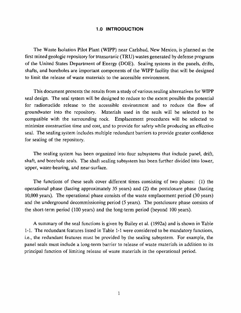
The Waste Isolation Pilot Plant (WIPP) near Carlsbad, New Mexico, is planned as the
first mined geologic repository for transuranic (TRU) wastes generated by defense programs
of the United States Department of Energy (DOE). Sealing systems in the panels, drifts,
shafts, and boreholes are important components of the WIPP facility that will be designed
to limit the release of waste materials to the accessible environment.
This document presents the results from a study of various sealing alternatives for WIPPseal design. The seal system will be designed to reduce to the extent possible the potentialfor radionuclide release to the accessible environment and to reduce the flow of
groundwater into the repository. Materials used in the seals will be selected to be
compatible with the surrounding rock. Emplacement procedures will be selected tominimize construction time and cost, and to provide for safety while producing an effective
seal. The sealing system includes multiple redundant barriers to provide greater confidence
for sealing of the repository.
The sealing system has been organized into four subsystems that include panel, drift,
shaft, and borehole seals. The shaft sealing subsystem has been further divided into lower,
upper, water-bearing, and near-surface.
The functions of these seals cover different times consisting of two phases: (1) the
operational phase (lasting approximately 35 years) and (2) the postclosure phase (lasting
10,000 years). The operational phase consists of the waste emplacement period (30 years)
and the underground decommissioning period (5 years). The postclosure phase consists of
the short-term period (100 years) and the long-term period (beyond 100 years).
A summary of the seal functions is given by Bailey et al. (1992a) and is shown in Table
1-1. The redundant features listed in Table 1-1 were considered to be mandatory functions,
Le., the redundant features must be provided by the sealing subsystem. For example, the
panel seals must include a long-term barrier to release of waste materials in addition to its
principal function of limiting release of waste materials in the operational period.
1
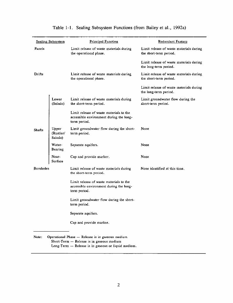
Table 1-1. Sealing Subsystem Functions (from Bailey et aI., 1992a)
Sealing Subsystem
Panels
Drifts
Lower(Salado)
Principal Function
Limit release of waste materials duringthe operational phase.
Limit release of waste materials duringthe operational phase.
Limit release of waste materials duringthe short-term period.
Redundant Feature
Limit release of waste materials duringthe short-term period.
Limit release of waste materials duringthe long-term period.
Limit release of waste materials duringthe short-term period.
Limit release of waste materials duringthe long-term period.
Limit groundwater flow during theshort-term period.
Shafts
Boreholes
Upper(Rustler/Salado)
WaterBearing
NearSurface
Limit relea<;e of waste materials to theaccessible environment during the longterm period.
Limit groundwater flow during the shortterm period.
Separate aquifers.
Cap and provide marker.
Limit release of waste materials duringthe short-term period.
Limit release of waste materials to theaccessible environment during the longterm period.
Limit groundwater flow during the shortterm period.
Separate aquifers.
Cap and provide marker.
None
None
None
None identified at this time.
Note: Operational Phase - Release is in gaseous mediumShort-Term - Release is in gaseous mediumLong-Term - Release is in gaseous or liquid medium.
2
1.1 Seal Requirements
The functional requirements for the WIPP sealing system are:
• Provide engineered barriers that will prevent WIPP excavations from becomingpreferred pathways for the release of waste materials in quantities that compromise
compliance with applicable regulations.
• Limit groundwater flow into the repository underground during the short-term toallow consolidation of the salt to take place.
• Form multiple barriers to gas/liquid flow at strategic locations.
Specific seal performance criteria for the various subsystems will be described In
sections of the report appropriate to that sealing subsystem.
1.2 Purpose of the Alternatives Study
The Initial Reference Seal System Design (IRSSD) (Nowak et aI., 1990) provides one
type of seal for each of the sealing subsystems. This study explores other types of sealswhich involve different sizes, shapes, materials, seal installation schedules, elimination or
addition of components, and remediation and maintenance requirements. Sealing
subsystems are evaluated qualitatively as to whether or not the sealing subsystem can meet
the performance criteria. The evaluation often is that engineering judgment deems one
alternative to have greater subjective probability of failure compared to another alternative,
despite the fact that both alternatives have a reasonable expectation for success. Cost
differences are developed for each alternative. Factors influencing the cost are size, shape,
materials, seal installation schedule, and remediation and maintenance requirements, and
for boreholes, the number of holes considered for sealing.
The alternatives study as performed did not include detailed cost comparisons or
technical evaluations. In that regard, neither specific recommendations nor comprehensiveperformance conclusions are made. Rather, alternatives are compared mostly in terms of
their advantages and disadvantages.
3
1.3 Report Organization
This report is organized as follows. Section 2.0 describes several rock mechanics issues
relevant to the design of seals or schedule for seal installation. Issues discussed include:(1) consolidation of crushed salt as a seal component, (2) the development and extent of a
disturbed rock zone around openings, and (3) the loading imposed on load-bearing seal
components. The results from rock mechanics studies are applicable to panel and drift
seals, shaft seals, and borehole seals.
Sections 3.0, 4.0, and 5.0 present the alternatives studies for panel and drift seals, shaft
seals, and borehole seals, respectively. In each of these sections, the reference seal designand seal materials are presented followed by discussions of alternative seal components,
materials, and schedules for installation, as appropriate. The alternatives for seal subsystems
in each section are then evaluated in terms of its favorable features and shortcomings and
order-of-magnitude costs. Future work required to validate or reconcile issues and
assumptions is identified where necessary.
Section 6.0 lists studies or future work that provide missing information or validateconcepts for the seal system. Section 7.0 provides a list of references for the report.
4

2.0 ROCK MECHANICS
Rock mechanics analyses were used to provide basic information on three concerns
relevant to the design of the sealing system:
1. The time required for consolidation of crushed salt or quarried-salt blocks into
a nearly impermeable seal material.
2. The development and extent of a disturbed rock zone (DRZ) around openings,
where such a DRZ may be in the salt or the interbeds and is time-dependent in
its characteristics.
3. The loading on rigid structures resulting from salt creep surrounding the
structure.
Information about each of these concerns is presented in separate sections In this
chapter. Whenever possible, the discussion of rock mechanics analysis uses normalized
results such that the same results can be applied to seal design in either panel and drift
seals, shaft seals, and borehole seals.
For most of the analyses, the thermomechanical finite-element program SPECTROM-32
(Callahan et aI., 1989) was used to model the mechanical behavior of the host rock
surrounding the opening and the concrete structure(s), if any. Four-noded, quadrilateral
elements were used in all of the finite element meshes. Material properties listed in the
preliminary Design Data Base Document (Bailey et aI., 1992b) were used unless otherwise
noted. For salt, the Munson-Dawson creep law and parameter values determined from
laboratory tests and field data verification analyses [e.g., Munson et al. (1992)] were used
in these analyses. For concrete, an elastic model was used. The following initial conditions
and assumptions were used:
1. For axisymmetric analyses, the WIPP stratigraphy can be ignored and an all-salt
medium assumed.
2. For plane strain analyses, the stratigraphy, with the exception of the location of
Clay Seams F and G, was modeled as shown in the preliminary Design Data
Base Document (Bailey et aI., 1992b) for the WIPP sealing system. The location
of Clay Seams F and G are modeled as shown in the WIPP alcove gas barrier
(AGB) final design report (Lin and Van Sambeek, 1992b).
5

3. The modeled excavations are sufficiently remote from other excavations that a
single-room in an infinite medium is representative.
4. The initial stress-state prior to excavation is lithostatic and equal to -14.76 MPa
at the WIPP horizon (655-m depth). The stress varies 0.0226 MPa/m above and
below the WIPP horizon from gravitational loading.
5. The mechanical behavior of the rock mass surrounding the excavation was
predicted using the material models and properties for halite, argillaceous halite,
anhydrite, polyhalite, and clay as given in the preliminary Design Data Base
Document (Bailey et aL, 1992b) for the WIPP sealing system.
6. The modeled region remains isothermal at 2rc.
7. The excavation and emplacement operations can be performed instantaneously
without impacting the utility of the results.
Similar assumptions and modeling approaches were used to model experiments and in situ
measurements at WIPP: South Drift, Room G, and Room D (Munson and DeVries, 1991;
1990), heated rooms (Munson et aI., 1990; 1991), heated pillar (Munson et aI., 1988), and
shaft closure measurements (Munson et aI., 1992).
2.1 Crushed Salt Consolidation
According to the WIPP IRSSD (Nowak et aI., 1990), reconsolidated crushed salt is the
principal long-term barrier to fluid flow. The crushed-salt emplacement density and the
time required to achieve reconsolidation to the desired density are two interrelated design
considerations. Modeling the consolidation of crushed salt within the WIPP seal system is
an intensive computational effort. The consolidation process is driven by the creep closure
of the opening, such that whenever the opening experiences a volume reduction because of
closure, the same volume reduction (by way of consolidation) is also experienced by the
crushed salt.
The development of internal stress in the consolidating crushed salt is a complex, time
dependent function of the current consolidation rate and the density. The stiffness of the
crushed salt in terms of its bulk and shear moduli can be related to the density (Sjaardema
and Krieg, 1987). Because crushed salt will consolidate by creep (e.g., Holcomb and Shields,
1987), the lowest possible stresses exist when the volumetric strain rate from creep
6

consolidation equals the imposed volumetric strain rate closure. When the two strain rates
are equal, none of the imposed volumetric strain is available for elastic volumetric strain,
which induces a stress increment. Therefore, so long as the closure rates for a salt-filled
opening are low, the stresses in the crushed salt will also be low until the density no longer
allows the crushed salt to creep consolidate at a fast enough rate. The density at which this
transition seems to occur is about 95 percent of the intact salt density (Holcomb and
Hannum, 1982; Holcomb and Shields, 1987).
One way to determine whether or not a region of crushed salt in the sealing system can
possibly achieve consolidation to a predetermined density within a desired time frame is to
inspect the expected closure history for the same region without crushed salt. A region
without crushed salt will always exhibit a faster closure rate than the same region with
crushed salt. Thus, if the region does not meet a time-to-consolidation objective without
crushed salt, it will never meet the same objective with crushed salt.
The volumetric strain, tv' required to consolidate crushed salt from a starting density
of Po to p is
(2-1)
where tv is negative for volume reduction. For example, to consolidate from a starting
density of 1,700 kg/m3 to 2,000 kg/m3 requires a volumetric strain of -15 percent. This
volumetric strain corresponds to the volumetric room closure required to cause the
consolidation. The density terms in Equation 2-1 can be either density or fractional density.
Numerical modeling analyses were made to determine the volumetric closure rates and
times required to achieve given amounts of closure for several geometric situations of
interest for drift and shaft seals.
2.1.1 Shaft Closure
Munson et al. (1992) describe an analysis that was performed to calculate the long-term
closure rates for shafts and boreholes. The results from their calculation were obtained
from the authors and used in this study. It is emphasized that the closure rates presented
7
by Munson and coworkers are for an empty opening in salt; that is, there is no lining or
crushed salt in the opening to impede closure.
The closure rate in various intervals of shafts and boreholes is highly dependent on the
depth of the interval. The lithostatic stress increases with depth and the closure rate is a
strong function of the stress state. The closure rate also depends on the time that has
elapsed between the excavation of the shaft or the drilling of the borehole and the time at
which the closure rate is desired. Munson et al. (1992) shows the influence of a 2D-year
elapsed period on the resulting time to achieve a given volumetric strain (areal closure) as
a function of depth.
The procedure and modeling results of Munson et al. (1992) were used to determine
the influence of a 50-year elapsed time between shaft excavation and shaft sealing. The
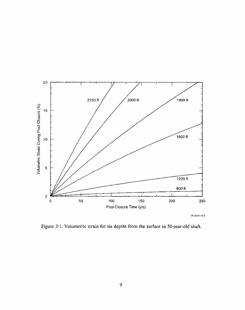
results are shown in Figure 2-1 for several depths in the shaft. In Figure 2-1, the closure
was converted to volumetric strain to facilitate determining the degree of consolidation
resulting from the closure.
At a depth of 2,000 ft, the volumetric strain increases from zero at 50 years after
excavation (time equal to zero in the figure) to 14 percent at 100 years after closure. If
crushed salt had been placed in the 50-year-old shaft, the crushed salt would have had to
consolidate 14 percent in order to accommodate the closure. This volumetric strain relates
directly to the change in density or fractional density as used in Equation 2-1. A caveat to
this example is that if crushed salt had actually been present in the shaft, the closure rate
will slow when the crushed salt began to develop internal stress, which in turn will slow the
creep of the surrounding salt. The information shown in Figure 2-1 must not be used
without recognizing this simplification.
2.1.2 Drift Closure
The design of the drift seals requires estimates of the consolidation rate of crushed salt
in the permanent seal region. An approximation of the consolidation rate for drifts was
obtained by converting open drift closure rates (no crushed salt or rigid structures) to a
volumetric closure rate quantity, which provides an upper-bound estimate of the
consolidation rate for crushed salt in the drift. It is emphasized that this procedure
produces a result that is only an order-of-magnitude result because the back pressure from
the crushed salt (or quarried-salt blocks) and the restraint from rigid structures will cause
8
20
;:g~~ 15:::lenooIenoa..OJc.§ 10oc.~
?is.Id...Q)
~ 5a>
oo 50 100 150
Post-Closure Time (yrs)
200
1200 ft
BOO ft
250
TRI·6121·72·0
Figure 2·1. Volumetric strain for six depths from the surface in 50-year-old shaft.
9
slower drift closure rates, and it is the drift closure rate that controls the consolidation rate
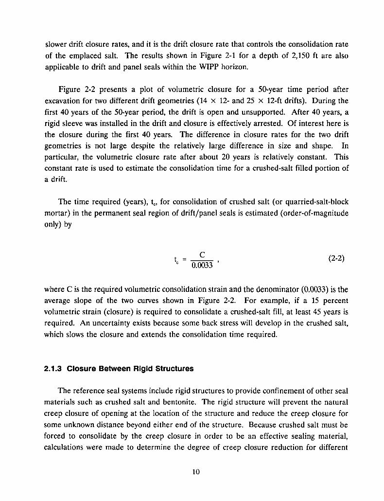
of the emplaced salt. The results shown in Figure 2-1 for a depth of 2,150 ft are also
applicable to drift and panel seals within the WIPP horizon.
Figure 2-2 presents a plot of volumetric closure for a 50-year time period after
excavation for two different drift geometries (14 x 12- and 25 x 12-ft drifts). During the
first 40 years of the 50-year period, the drift is open and unsupported. After 40 years, a
rigid sleeve was installed in the drift and closure is effectively arrested. Of interest here is
the closure during the first 40 years. The difference in closure rates for the two drift
geometries is not large despite the relatively large difference in size and shape. In
particular, the volumetric closure rate after about 20 years is relatively constant. This
constant rate is used to estimate the consolidation time for a crushed-salt filled portion of
a drift.
The time required (years), te, for consolidation of crushed salt (or quarried-salt-block
mortar) in the permanent seal region of drift/panel seals is estimated (order-of-magnitude
only) by
Cte = -=-0.-=-00=-=3-=-3
(2-2)
where C is the required volumetric consolidation strain and the denominator (0.0033) is theaverage slope of the two curves shown in Figure 2-2. For example, if a 15 percent
volumetric strain (closure) is required to consolidate a crushed-salt fill, at least 45 years is
required. An uncertainty exists because some back stress will develop in the crushed salt,
which slows the closure and extends the consolidation time required.
2.1.3 Closure Between Rigid Structures
The reference seal systems include rigid structures to provide confinement of other seal
materials such as crushed salt and bentonite. The rigid structure will prevent the natural
creep closure of opening at the location of the structure and reduce the creep closure for
some unknown distance beyond either end of the structure. Because crushed salt must be
forced to consolidate by the creep closure in order to be an effective sealing material,
calculations were made to determine the degree of creep closure reduction for different
10
25
20
~e.....Q) 15...:Jen0
<:5u-.:::a;E 10:J"0>
5 /,
oo 5 10 15 20 25 30 35 40 45 50
Time Since Excavation (yrs)
Figure 2-2. Volumetric closure for two rectangular-shaped drifts.
11
TRI-S121-73-Q
spacings between rigid structures.
Rigid structures in an opening will retard the closure of the opening both in the
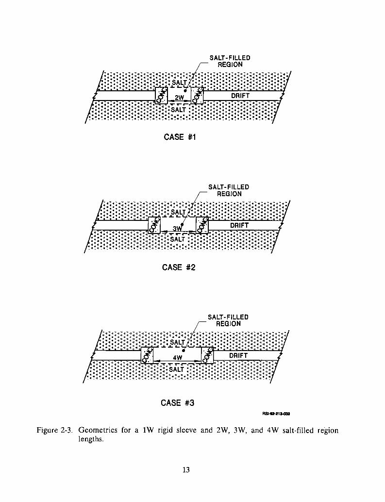
immediate area of the structure and for some distance on either side of the structure. Thegeometric situations modeled to study the influence of rigid structures on the closure
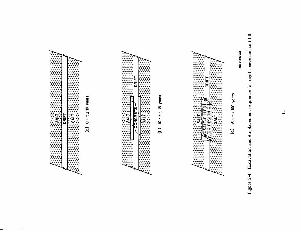
between the structures are shown in Figure 2-3. The following steps (which are also shown
in Figure 2-4) were included in the analysis:
1. Excavate a circular opening of sufficient length to simulate a very long opening
in a homogeneous material. (The diameter of the opening (W) is not important
to the results as no stratigraphy is included in the models).
2. Analyze the creep of the salt surrounding the unsupported opening to 10 years.
3. Install a rigid sleeve over an appropriate length of the opening; for example, five
times the diameter of the opening (5W) in the case of the eventual3W salt-filled
region.
4. Analyze the creep of the salt surrounding the supported and unsupported areas
of the opening for an additional 5 years.
5. Remove the sleeve in the central portion of the supported opening to produce
the region to be filled with salt (for example, 3W-Iong in the case of the 3W
backfilled region). Convert the two 1W-Iong sections of rigid sleeve tomonolithic structures, one at each end of the salt-fill region. Record the liner
loading on the monolithic structures after the removal of the central portion of
the rigid sleeve.
6. Analyze the creep of the salt for the new geometry to about 100 years. Record
the closure of the central portion (salt-filled region - although no salt fill is
actually emplaced). Also record the liner loading on the monolithic structures.
The numerical modeling results for the different geometrical situations show that the
volumetric strain from room closure is relatively uniform between the two monolithic
structures. The closure is restrained by the rigid sleeve to a distance of about 1 openingradius into the central portion from each rigid sleeve. This is in agreement with earlier
calculations made by Argiiello (1988).
In terms of cumulative room closure (volumetric strain) for the three cases, the greater
the span between rigid sleeves, the greater the volumetric strain, although the difference is
12
SALT-FILLEDREGION
CASE #1
SALT-FILLEDREGION
CASE #2
SALT-FILLEDREGION
CASE #3
Figure 2-3. Geometries for a 1W rigid sleeve and 2W, 3W, and 4W salt-filled regIonlengths.
13
--;;::....-(\$en
I"0
'" c::vvvv (\$lVVVV
~VVVVV v V7 V V V V VVV VVV VVV
~>VVV?V VVVVV' VVVVV' VVVV9'~lV?VV VVVVV VVVVV QVV9V~
VVVVV VVVVV' VVVOV' VVOVV' II:lVVVO V9VVV VVVVV 19VVVV ";;jVV9VV VVVVV' VVVVV· VVVVV·1 V V V V VVVVV OVVVV vvvov "0vvvvv VVVVV' VVVVV· VVVVV· .-7VVVV VVVVV VVV?V 9VQ9V 00V V V V V VVVVV' VV9VV' VVVVV'lV?V? VVVVV 'lVV,",V lVVVVV ·CVVVVv VVVVV' VVVVV' vvvvv·1'1'1'1'1 VVVVV vvvvv 7VVVVV ~vvvvv VVVVV' VVVVV' V V 'J V t" .BlVVVV VVVVV vvvvv qVVVVvvvvv "V V V V' 'l1VVVV' vvvvv·lVVVV VVV9V vv'Vvv lVVVVV~VVV9V VVVVV' vvvvv' vvvvv· Co)lVVVV vvvvv VVVVV 1VVVVV en c::vvvvv vvvvv' '1 V V V V' en :alVVVV vvvvv en vvvv :a ~vvvvv VVVVV' :a V V V V' CI) ;::3lVVVV vvvvv VVVV CD >-vvvvv vvvvv' CI)
V V V V' >- CT'1 V V V V VVVVV >- VVOV 0 ~VVVVv VVVVV' V V V V' 10 0 enlVVVV VVVVv 0 vvvv .... ....vvvvv VVVVV' .... V V V V' .... VlVVVV VVVVVvi VVV'l vi vl c:: -V V V ... • V' ..
~'V ~V VV~ 'l'1'1. - ~ VV - - EV '1:..J V LL :...J V' v ...,,v <V a: '19 < VV~ v < VV
~,VVV Cl'JVV en V' 0 10C 'VC/)V'l 0 VV Co)VV99V '1'1'19'1' V 9 V V'
.... ....(\$'V V V 9 VVVv'l - VVVV
0.VVVVV VVVVV' V V V V' - -'V V V V VVVVV tU VVVV .0 0 EVVVVV VVVVV' - V V V V' - -'VVVV VVVVV VVVV~
'1'1'1'1'1 VVV?V' V V V V''VVVV VVVVV VVVV
"0VVVVV VV'1VV' V V V V'''1V'1V VVVVV VVVVV c::VVVVV VVVVV' VVVVV'
(\$lVVVV VVVVV VVVVV9V9VV VVVVV' VV'1'1V' c::1V'1VV VVVV'l VVVVVVVVVV VVVVV' VVV'1V' 01VVVV VVVV'l VVvvV .-VOVVV VVVVV' VVVVV' ....'VVVv VVVV'l VVVVV (\$VVV'1V VVVVV' V'1'1'1'1'
~1'1'lVV '1VVVV VV'1'1VV'1'1VV VVVVV' V V '1 V V·
Co)1VVVV '1VVV'l VV'1VV
><.'1 V V '1'l'1VV' V'l'1VV''V'lVV'1 '1V'1'1'1 rJJ'1'lVVV' '1VVVV'
V'1VV V'1V'1.' !" ..V
I
N~~
So.-~

not large. The volumetric strains at the midlength of the salt-filled regions are shown in
Figure 2-5 for the 2W-, 3W-, and 4W-Iong central portions.
2.2 DRZ Around Openings
2.2.1 Types of DRZ
It is commonly recognized that a disturbed rock zone (DRZ) develops around any
underground excavation. At the WIPP, a DRZ is defined by J.e. Stormont in the 1991
memorandum titled "An Approach to Address DRZ Development and Healing in Rock" as
that region near an excavation that experiences a change in its hydrologic or mechanical
properties. Boreholes in the roof, floor, and ribs at WIPP have revealed fracturing within
the first meter beyond the excavation surface. Some of the fracturing, particularly that in
interbeds (anhydrites, clays, polyhalites, and argillaceous halite), increases in frequency and
aperture through time. In general, the DRZ consists of an "initial" DRZ that develops
upon excavation of the opening and a "secondary" DRZ that develops in the salt and
interbeds because of the creep deformation of the salt and the stress redistribution as a
consequence of creep. A DRZ is generally assumed to have the following characteristics
(e.g., Stormont, 1990; Stormont et aI., 1987; and Stormont et aI., 1991):
• Increased volume resulting from micro- or macro-fracturing,• Decreased load-bearing capacity, and• Increased fluid (gas or liquid) permeability.
2.2.1.1 DRZ IN SALT
Studies of the development of a DRZ in salt lead to the conclusion that the DRZ is
intimately tied to the stresses that occur in the zone. In particular, certain combinations of
applied stresses cause dilation in laboratory tests on salt cores. The stress states can be
represented by stress measures describing the bulk pressure (mean stress or first invariant
of the total stress tensor) and shear stress (second invariant of the deviatoric stress tensor).
The two stress measures signal both the development of the DRZ in rock salt and the
healing of damage (e.g. fractures) within salt.
Two efforts at characterizing the DRZ in WIPP salt use the assumption that the extent
of the DRZ (at any time) can be determined through an examination of the two
15

25%·....-------------------------------.
4W3W2W/<::.:::.::
- .', .'~",~=~ ., .'
*,' •••••
" ..., .',41' ••••," ...." ..., .'," ...., .'" ...., .',,' ....., .', .', .', .', .', .', .', .', .'/ ....
'"/.:,..<.'
§ 20%00)Q)~
~-c~.ccon;~
1i5(J
0t:CDE 5%:]
g
O%.+---_r_--.----r-----r--~--_,_--_r_--_r_--_r_-___i
o 10 20 30 40 50 60 70 80 90 100
Time since liner removal (years)RSI·213-ll2-07O
Figure 2-50 Volumetric strain at the center of the region between the rigid sleeveso
16
instantaneous values of the aforementioned stress invariants (Ratigan et al., 1991 and
Stormont 1991 memorandum, as cited above). Another effort is pursuing the development
of a rate-based constitutive model with mechanistically based, stress-invariant dependence
that requires integration of the rate equations to determine DRZ extent (Fossum et al.,
[1992]). Each effort recognizes that the DRZ is a zone of damaged rock that has
experienced an increase in volume, which is commonly referred to as dilation, and is
attributable, at least in part, to microfacturing.
Ratigan et al. (1991) proposes that the states of stress that do and do not cause dilation
in laboratory creep tests are separated by the relationship
II: = 0.27 II '(2-3)
where J2
is the second invariant of the deviatoric stress tensor and II is the first invariant
of the total stress tensor (II = 3 CTm)' This equation can be used to determine the potential
for a DRZ whenever the stress state is known or can be calculated.
2.2.1.2 DRZ IN INTERBEDS
The anhydrite of Marker Bed 139 (MB139) is the closest major interbed to the panel
and drift seal locations. The anhydrite is brittle, unlike the WIPP salt. When an excavation
is made a short distance above MB139, the rock stress at the boundary of the opening is
reduced to zero, creating an upward thrust on the bed. The bed deforms upward toward
the excavation because of both elastic and creep deformation of the salt. The deformation
of MB139 is most severe directly under the excavation, but deformation of MB139 extends
under the adjacent pillars as well. The deformation will produce a DRZ within MB139,
which is characterized by micro- and possibly macro-fractures. When fractures develop in
MB139, the permeability of the interbed will increase significantly, and such fracturing is not
expected to heal naturally, except by long-term mineralization. Grouting should reduce the
permeability; however, the effectiveness of grouting is diminished if the salt continues to
creep toward the excavation, resulting in further deformation and potential continued
fracturing of MB139.
Clay seams also exist near the WIPP excavations. Characterization of DRZs around the
day seam interbeds has not been performed. It is possible that the zone of damage outside
17

the seam itself is small because the "clay" is weak and will yield before allowing shearing
stresses to build to the point where the surrounding rock (salt) is damaged.
2.2.2 Opening-Shape Effects
2.2.2.1 CIRCULAR OPENINGS
A necessary element of the conceptual design of a shaft seal within the Salado
Formation is determining the thickness of the DRZ around the shaft after standing unlined
for 30 to 50 years. A first approximation of the thickness of the DRZ will be made in this
subsection using analytical solutions for the stress distributions in the salt around the shaft
and a salt damage criterion based on stress invariants.
The calculation could also be made using numerical modeling methods, but modeling
the problem is a more intensive effort and is beyond the scope of a first approximation.
The analytical solution for the stress distributions are available, for example, in Van
Sambeek (1986). The analytical solution applies only if the following conditions are met or
assumed:
1. No creep strain occurs in the direction parallel to the axis of the shaft, and
2. The creep behavior of the salt can be described by a Norton-type creep law, acondition that applies a long time after excavation (i.e., after any transient creep
phase has ended).
A condition of stationary stress, as defined by Van Sambeek (1986), is assumed to exist
around the shaft at the time of sealing; that is, some 30 to 50 years after shaft excavation.
Moreover, a condition of zero vertical creep displacement is assumed in order to meet the
"axially restrained" condition. An axially restrained condition is not truly appropriate
because subsidence is known to occur, but the vertical strain is believed to approach zero
at moderate distances above the repository horizon.
According to Van Sambeek (1986), the stationary stress distributions around a circularopening in an infinitely extending material whose creep behavior can be modeled by a
Norton-type creep law are
18
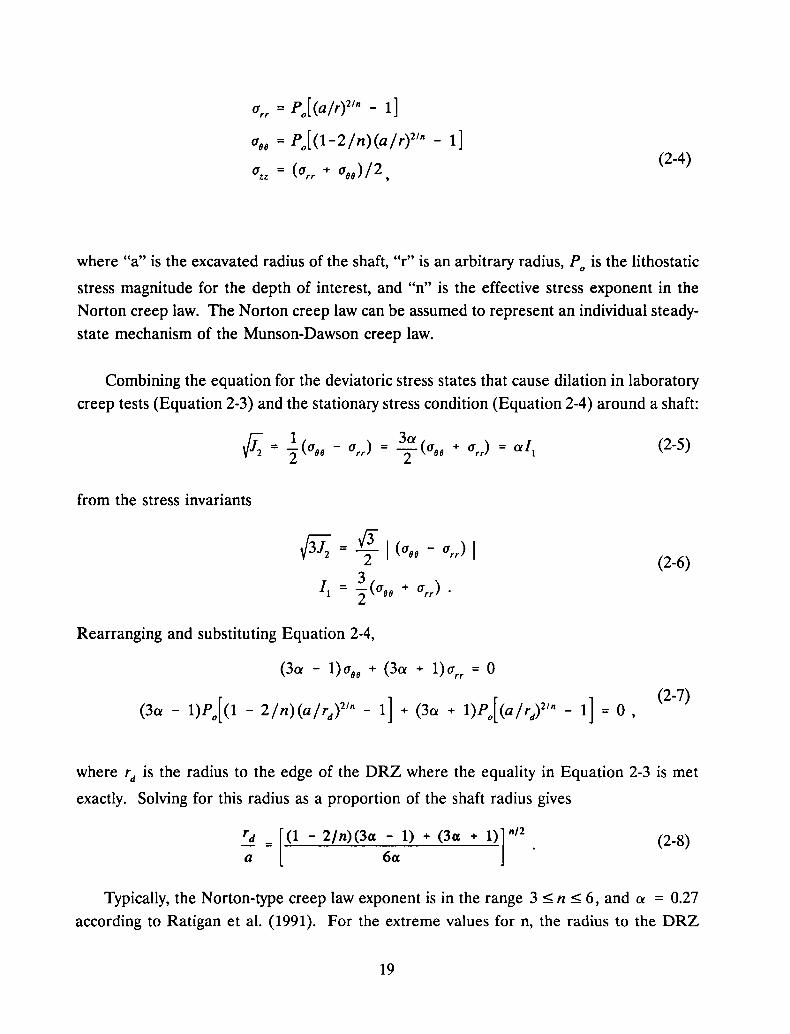
(Jrr =pJ (a/r)21n - 1]
(Jee = pJ(1-2/n)(a/r)2/n - 1](2-4)
where "a" is the excavated radius of the shaft, "r" is an arbitrary radius, Po is the lithostatic
stress magnitude for the depth of interest, and "n" is the effective stress exponent in the
Norton creep law. The Norton creep law can be assumed to represent an individual steady
state mechanism of the Munson-Dawson creep law.
Combining the equation for the deviatoric stress states that cause dilation in laboratory
creep tests (Equation 2-3) and the stationary stress condition (Equation 2-4) around a shaft:
(2-5)
from the stress invariants
Rearranging and substituting Equation 2-4,
(3a - 1)(Jee + (3a + 1)(Jrr = 0
(3a - 1)Po [(1 - 2/n)(a/rd
)2/n - 1] + (3a + 1)Po[(a/rd)2/n - 1] = 0,
(2-6)
(2-7)
where rd is the radius to the edge of the DRZ where the equality in Equation 2-3 is met
exactly. Solving for this radius as a proportion of the shaft radius gives
rd = [(1 - 2/n)(3a - 1) + (3a + 1)] 11/2
a 6a(2-8)
Typically, the Norton-type creep law exponent is in the range 3 ::5; n ::5; 6, and a = 0.27
according to Ratigan et al. (1991). For the extreme values for n, the radius to the DRZ
19
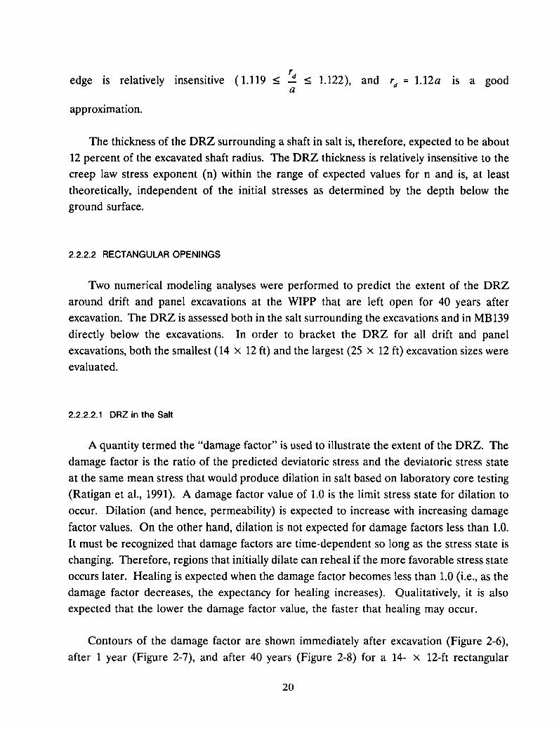
'dedge is relatively insensitive (1.119 ~ ~ 1.122), and 'd = 1.12a IS a gooda
approximation.
The thickness of the DRZ surrounding a shaft in salt is, therefore, expected to be about
12 percent of the excavated shaft radius. The DRZ thickness is relatively insensitive to the
creep law stress exponent (n) within the range of expected values for n and is, at least
theoretically, independent of the initial stresses as determined by the depth below the
ground surface.
2.2.2.2 RECTANGULAR OPENINGS
Two numerical modeling analyses were performed to predict the extent of the DRZ
around drift and panel excavations at the WIPP that are left open for 40 years afterexcavation. The DRZ is assessed both in the salt surrounding the excavations and in MB139
directly below the excavations. In order to bracket the DRZ for all drift and panel
excavations, both the smallest (14 x 12 ft) and the largest (25 x 12 ft) excavation sizes were
evaluated.
2.2.2.2.1 DRZ in the Salt
A quantity termed the "damage factor" is used to illustrate the extent of the DRZ. The
damage factor is the ratio of the predicted deviatoric stress and the deviatoric stress state
at the same mean stress that would produce dilation in salt based on laboratory core testing
(Ratigan et aI., 1991). A damage factor value of 1.0 is the limit stress state for dilation to
occur. Dilation (and hence, permeability) is expected to increase with increasing damage
factor values. On the other hand, dilation is not expected for damage factors less than 1.0.
It must be recognized that damage factors are time-dependent so long as the stress state is
changing. Therefore, regions that initially dilate can reheal if the more favorable stress state
occurs later. Healing is expected when the damage factor becomes less than 1.0 (Le., as thedamage factor decreases, the expectancy for healing increases). Qualitatively, it is also
expected that the lower the damage factor value, the faster that healing may occur.
Contours of the damage factor are shown immediately after excavation (Figure 2-6),
after 1 year (Figure 2-7), and after 40 years (Figure 2-8) for a 14- x 12-ft rectangular
20

Clay seam G
1.5
0.0 1----------------------......-1.5 i-tti{~;l.
.....::.-3.0
-!>0 -4.5
-6.0
-7.5
-9.0
MB139
Clay seam F
Damage Factor (D)
I:·:· 0.8 < D < 1.0D> 1.0
Clay Seam E
0.0 1.5 3.0 4.5 6.0
X (m)
7.5 9.0 10.5 12.0
Figure 2-6. DRZ in salt around a 14- x 12-foot excavation immediately after excavation.
21
1.5
Clay seam G
0.0 1!-------------------------4-1.5
-3.0
>0 -4.5
-6.0
-7.5
-9.0
MB139
Clay Seam F
OlUllage Factor (0)
I:·:· 0.8 < 0 < 1.00> 1.0
Clay Seam E
0.0 1.5 3.0 4.5 6.0
X (m)
7.5 9.0 10.5 12.0
RSI-82·213-Q35
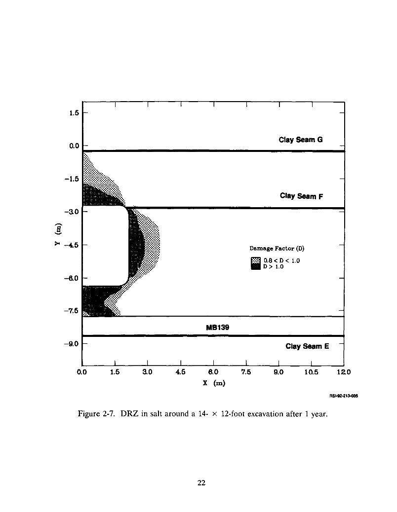
Figure 2-7. DRZ in salt around a 14- x 12-foot excavation after 1 year.
22

1.5
Clay Seam G
Clay seam F
Damage Factor (D)
I·:::: 0.8 < D < 1.0D> 1.0
MB139
.....
~t%?"
.....•:::;;~~::::::::~:::;.......
0.0 p ~
!It]'~f~+.:••:.
-1.5
-3.0
-7.5
-6.0
-9.0 Clay Seam E
0.0 1.5 3.0 4.5 6.0X (m)
7.5 9.0 10.5 12.0
RS1-2130820040
Figure 2-8. DRZ in salt around a 14- x 12-foot excavation after 40 years.
23

excavation. Immediately after excavation, a significant amount of salt surrounding theexcavation experiences stresses which will cause damage. Within 1 year after excavation,
the damaged zone is almost completely developed. Only very small increases in thecross-sectional area of the DRZ in the WIPP salt are predicted between 1 and 40 years.The fully developed DRZ for the 14- x 12-ft excavation extends from the floor of theexcavation to MB139. The DRZ extends a maximum of about 1 m horizontally into the
pillar and about 1.5 m above the excavation.
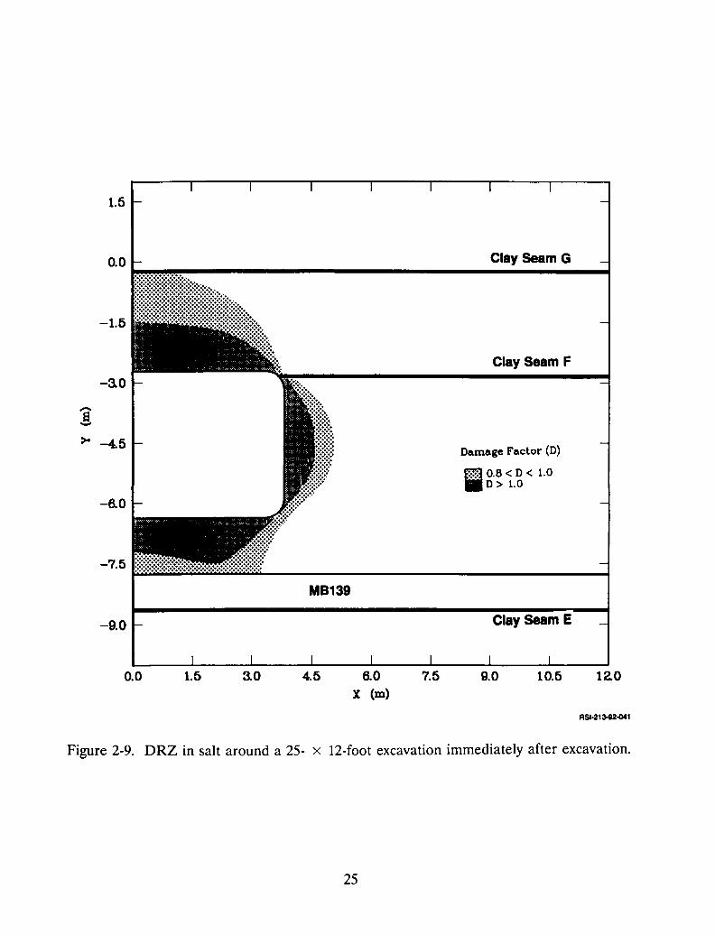
Figures 2-9 through 2-11 show contours of the damage factor for a 25 x 12-ft
rectangular excavation. Similar to the 14- x 12-ft excavation, most of the DRZ is developedduring the first year after excavation. However, growth of the DRZ above the excavation
over the 40 years is somewhat larger than that seen for the 14- x 12-ft excavation. The fullydeveloped DRZ for the 25- x 12-ft excavation extends from the floor of the excavation toMB139. The DRZ extends to a maximum of about 1 m horizontally into the pillar and
about 2.75 m above the excavation.
2.2.2.2.2 DRZ in Marker Bed 139
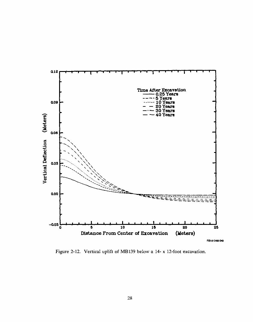
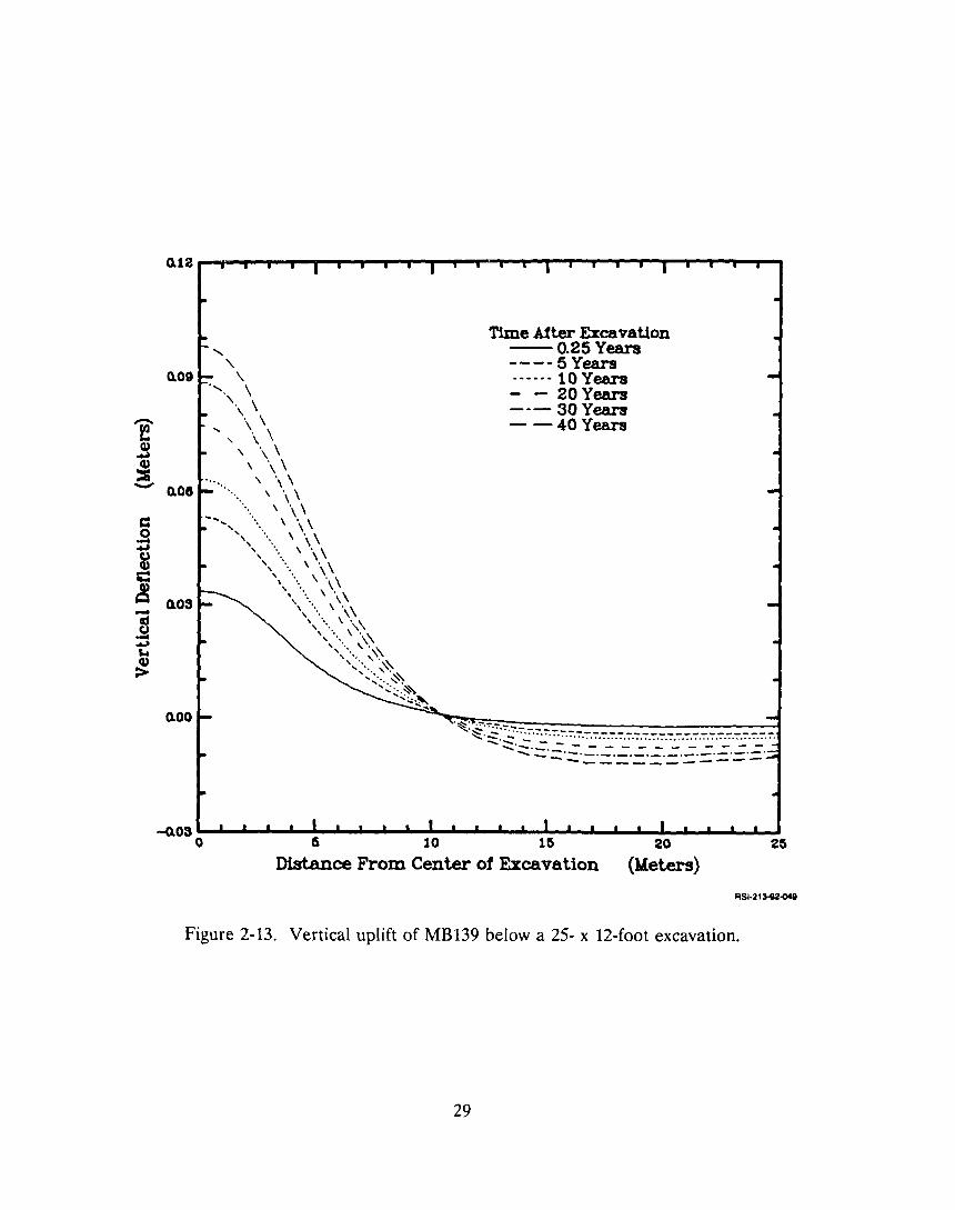
Figures 2-12 and 2-13 show the calculated vertical deflection (uplift) of the top ofMB139 at various times for the 14- x 12- and the 25- x 12-ft excavations, respectively. Themaximum uplift occurs at the center of the excavation. The maximum for the 14- x 12-ftexcavation uplift is about one-half of that for the 25- x 12-ft excavation. The uplift ofMB139 is most rapid immediately after excavation and slows with time as evidenced by the
deflection curves.
The potential for yielding (based on the Drucker-Prager yield criterion) in MB139 for
the two excavation geometries was examined for both geometries. Although the confidence
in the analysis results is not high because material properties of this anhydrite are not well
defined, a qualitative comparison of the influence of excavation geometry can be made.Yielding was not indicated in the finite element analysis until 10 years after excavation forthe 14- x 12-ft opening and the severity of damage continued to increase for the duration
of the simulation. By 40 years, most of the marker bed within 10 m of the excavationcenterline showed a high potential for yielding. For the 25- x 12-ft excavation, yielding in
the marker bed was possible within the first year after excavation. Similar to the smallerexcavation, the potential for yielding in the marker bed continued to increase throughout
the duration of the simulation.
24
1.5
Clay seam F
Damage Factor (D)
Effi 0.8 < D < 1.0.D> 1.0
. ., I •
• >,. .~< .. ,H ~"" ~ ".. ; "n,
o0 Clay seam G
.~~~---------------.....;;,----~
illllr!!I:I~!lb~..
-6.0
-3.0
-1.5
>0 -4.5
-7.5 Fi:i:i:.i:.i::O:O:O:O:'i:i:i:.i:.i::O:O:O:O:'i:i:i:.i:.i::o:o:o:o:......-.--------- --1
MB139
-9.0 Clay seam E
0.0 1.5 3.0 4.5 6.0x (m)
7.5 9.0 10.5 12.0
RSI·213-e20041
Figure 2-9. DRZ in salt around a 25- x 12-foot excavation immediately after excavation.
25

1.5
0.0
-1.5
-3.0
>--4.5
-6.0
-7.5
-9.0
MB139
Clay seam G
Clay seam F
Damage Factor (D)
00 0.8 < D < 1.0.D> 1.0
Clay seam E
0.0 1.5 3.0 4.5 6.0
X (m)
7.5 9.0 10.5 12.0
RSI·213-820042
Figure 2-10. DRZ in salt around a 25- x 12-foot excavation after 1 year.
26

Clay Seam G
Clay Seam F
Damage Factor (D)
frn 0.8 < D < 1.0• D> 1.0
......
.-:.:.-..::::::~..:::::::::%::.
l.i'111rlttl'llll~,..-------------------.....0.0
1.5
-7.5
-6.0
-1.5
-3.0
>- -4.5
MB139
-9.0 Clay Seam E
0.0 1.5 3.0 4.5 6.0:x (m)
7.5 9.0 10.5 12.0
RSI·213-ll2~7
Figure 2-11. DRZ in salt around a 25- x 12-foot excavation after 40 years.
27
0.09
fcu~cu:s- o.os
c:0....~t)cu--~ 0.03-5....~s..cu>
0.00
Time After ExcavaUon-0.25Years---- 5 Years------ 10 Years- - 20Years--- 30 Years- -40 Years
-0.03 _ _ _-.10 _ -.10 _
o 0 10 10 20 20
Distance From Center of Excavation (Meters)
Figure 2-12. Vertical uplift of MB139 below a 14- x 12-foot excavation.
28
0.12----~........,..............,~r__,...~.,....,.....,..._r_..,.."""T~....,.....,r_r_,....~
Time After E%cavation-0.25Years---- 5 Years...... 10 Years- - 20 Years--- 30 Years- -40 Years
'.
" "-\
". \'. \
'. \.... , \ \
, \ \\ \ \
\ \ \\ ,,\
. \" \--', ..... \" \
", .... \" \" ..... \ ,,\
" ... \ ,,\" .... \ ',\, .\ .... \ \\" .... \ \\', .... \ ',\
', .... \ \\','" ,. ,,". ,'\:-
',.... ""'<.....~\'-:"'~
....':.:~
o.oe
0.09
0.00
-Q.03 ....",.....I'-- ..r- --' ~ --' .........o 5 10 15 20 25
Distance From Center of Excavation (Meters)
RSI·21 :H20048
Figure 2-13. Vertical uplift of MB139 below a 25- x 12-foot excavation.
29

In summary, numerical modeling suggests that around rectangular openings the DRZ
in salt develops to almost its full extent in the first year after excavation. The calculated
expansion of the DRZ during the time period from 10 years to 20 or 35 years after
excavation is negligible [e.g., compare Figure 2-7 to Figure 2-8]. The DRZ in the interbeds
(particularly MB139) does continue to expand, but at a diminishing rate. For instance, the
uplift of MB139 shortly after excavation is about one-third the long-term uplift (40 years).
Two-thirds of the uplift occurs in the first 10 years. The zone of yielding within the MB139
expands throughout the 40 years in direct response to the imposed uplift. The size of the
zone for which yielding of the rock is suggested by a Drucker-Prager failure criterion is not
well defined because of uncertainty in material properties presently available for use in
calculations.
Another consideration is the uplift and deflection of MB139 below the salt seal portion
of drift seals during the consolidation period (see Section 2.1.2). Based on the volumetric
closures shown in Figure 2-2 and the MB139 uplifts shown in Figures 2-12 and 2-13, about
2.5 and 3.5 mm uplift occurs at the centerline of 14- x 12- and 25- x 12-ft drifts for each
1 percent closure. Thus, for 15 percent closure, about 40- to 55-mm uplift could occur
during the crushed-salt consolidation. Uplifts of this magnitude are of the same order as
what occurs during the first 10 years after excavation.
Installing a rigid sleeve in the existing 25- x 12-ft drifts will soon prevent accumulationof additional deformation in the salt and marker bed, but the most significant damage would
already have occurred before the rigid sleeve is installed. One benefit of installing a rigid
sleeve (regardless of when it is installed) is preserving the integrity of the salt rock in the
roof. If the roof rock will fall at some time during the operational phase, perhaps it is
better to have a sleeve in place to hold the roof rock there, rather than having to fill a void
later.
2.2.3 Stratigraphical Influences
It is possible that particular stratigraphic units might influence the DRZ in other
stratigraphical units beyond that considered above. For example, a clay seam is modeled
at the bottom of MB139, and it possibly influences the extent of the DRZ in salt below
MB139 and the calculated factors-of-safety within MB139. A question remains concerning
30
whether or not a similar weak seam or sliding interface should also be modeled above
MB139 to debond the anhydrite from the salt.
It is also emphasized that the mechanical and strength properties for MB139 may not
be representative of the anhydrite. Laboratory testing on representative samples of MB139
material are being performed. Preliminary, unpublished results indicate that the material
being tested is less stiff (lower Young's modulus) and weaker (lower unconfined compressive
strength) than indicated by the properties listed in the preliminary Data Base Document
(Bailey et al., 1992b).
2.3 Loading on Rigid Structures Emplaced in Salt
Rigid structures are included in the seal system to provide confinement of seal materials
such as crushed salt, bentonite, or asphalt, or to prevent the natural creep closure of an
opening as a means of avoiding damage in the salt and interbeds. Whenever a rigid
structure is placed in contact with salt, loading will develop on the structure because the
structure restrains the salt creep. If the rigid structure was infinite in length, the loading
magnitude would eventually equal the lithostatic stress in the salt and the salt would no
longer creep. The rigid structures in the sealing system are finite in length, however, and
the liner loading will eventually exceed the lithostatic stress because of stress concentration
and end-effect loading. A series of analyses was performed to determine the time
dependent characteristics and magnitudes for loading based on different schedules and
geometries for the rigid structures.
The need for a confinement structure at both ends of the crushed-salt-filled region of
the drift and panel seals has not been demonstrated. If redundant operational seals are not
required, one of the rigid structures can possibly be omitted and a longer region of crushed
salt can be used to provide any required confinement. The confinement structure issue will
require additional study relative to operational seal requirements.
2.3.1 Schedule Effects on Loading MagnitUde
The loading that develops on rigid structures emplaced in salt results from restraining
the creep closure of the opening. The long-term load on the structure must be the sameregardless of when the structure was installed relative to the time of excavating the opening.
31
However, the short-term loading, i.e., during a few years after installation, may be a function
of the length of time the opening was allowed to creep unrestrained. It is intuitively
expected that the sooner a rigid structure is installed after excavation, the faster the loading
will develop. If the design life is within the ''window'' for the faster loading, then a larger
design loading must be accounted for. This aspect was studied in the following manner.
The axisymmetric geometry for the calculations described in Section 2.1.3 was
reanalyzed with a different time sequence for excavation and liner installation. Two
analyses were performed; in one case the liner was installed 5 years after excavation and in
the other it was installed 35 years after excavation. The liner loadings as a function of time
after installation are shown in Figure 2-14. The development of loading is moderately
influenced for a 5-year design life (the design load would need to be increased from about
9 MPa to 13 MPa.) However, for a 50-year design life, the design loads are about the same.
2.3.2 Geometrical Effects on Loading Distribution
A calculation involving three different geometries was described in Section 2.1.3. The
liner loadings from that calculation are discussed here. The liner loading for the three
different geometries is essentially the same. The only difference noted is that the liner
loading increases somewhat faster initially for the longer unsupported spans, but by 50 years,
the liner loadings are the same for all three cases. The eventual average load on the lineris about 17 MPa (2,500 psi) in the center and about 25 MPa (3,600 psi) at the edges; these
values are, however, specific to a liner whose length equals its diameter.
2.3.2.1 EFFECT OF OPENING SHAPE
Lin and Van Sambeek (1992a) present numerical modeling results concerning the
variation in liner loading around circular and horseshoe-shaped liners. The variation is
small and subsequently there is no need to incorporate special design considerations.
2.3.2.2 EFFECT OF INTERBEDS
Lin and Van Sambeek (1992b) present numerical modeling results that show the
influence of interbeds (i.e., the clay seams and MB139 are most significant) on liner loading.
32

2(h--------------------------,
-- 5years....•.... 35 years
Time between excavationand liner installation
16
4
...._.....•.....- _ .......-...._..o
oo
oo
o,o
oo
oo
oI
oo
..-o
o:
oo
oo
ooo.
o,o..,.,.
o,o•
o 10 20 30 40 50 60 70 80
Time after liner installation (years)90 100
RS1-21~
Figure 2-14. Liner loading as affected by delayed liner installation.
33
The clay seams cause some variation in liner loading above and below the contact with the
liner, but the effect is small. The influence of MB139 on the liner loading distribution
depends on the thickness of salt between the liner and MB139. For a thickness of 4 ft or
more, MB 139 does not affect the distribution enough to warrant special design consider
ation.
34
3.0 DRIFT AND PANEL SEALS
The alternatives study for drift and panel seals has two objectives:
• To evaluate design alternatives to the initial reference seal system design (IRSSD)
(Nowak et aI., 1990), and
• To define future study required for the preliminary design of the drift and panel
seals.
The study was performed in the following steps. First, the requirements for the driftand panel seals, as defined in the Design Requirements Document (DRD) and IRSSD, were
studied to determine both the function- and performance-related issues that could beaddressed by different design alternatives. These preliminary requirements are discussedin Sections 3.1 and 3.2. The reference seal design is also briefly described in terms of the
components involved and the number and location of the drift and panel seals (Section
3.2.1).
Second, considerations for alternatives to the reference design were developed, such assize of excavations, the DRZ at seal locations, schedule, cost, and modifications of thesealing requirements. Together with these considerations, assumptions were formulated(Section 3.3) that address schedule uncertainties, operational needs, and construction costs,
regardless of the specific alternative. Evaluation criteria are presented in Section 3.4. The
rock mechanics aspects of the design for various alternatives were based on the information
presented in Section 2.
Third, a series of types of design were developed based on considerations for whenvarious seal construction was to occur (Le., now versus later) and the size of excavations.These design types were further developed into different arrangements of seals and differentoptions within the same design type to explore cost variations. The descriptions of the seal
designs, arrangements, and options are presented in Section 3.5.
Finally, the alternatives are discussed in terms of effectiveness, constructibility, and cost.The evaluations are discussed in Section 3.6. Conclusions about the arrangements andoptions are discussed in Section 3.7. Recommendations for future work and technology
development were also identified and are discussed in Section 6.0.
35

3.1 Purpose of the Drift and Panel Seals
The principal function of the panel seals is to limit the release of hazardous material
from filled disposal rooms during the operational phase to meet EPA requirements. The
reference seal-design (Nowak et aI., 1990) uses components which consist of a permanentsalt seal placed between two concrete monoliths seals. The monoliths are operational seals
which limit release of waste by providing resistance to gas flow and confine the crushed salt
of the long-term seal. Confidence for sealing during the operational phase is bolsteredbecause access will exist for remedial maintenance, ventilation, and monitoring.
In addition to the reference design, other design options should also be considered for
decision making. Such options may entail the timing of seal emplacement; viz, whether
action needs to be taken immediately prior to the development of an emplacement panel,
or construction of the seal should start subsequent to waste emplacement in the panel.
Design options may also include various shapes and sizes and construction materials.
Further, before a decision can be made, cost estimates for various options are needed.
This study provides the information on the impact of shapes, sizes, constructionmaterials, timing and cost, and discusses the pros and cons, including performanceevaluation, of the various design options.
3.2 Requirements
3.2.1 Reference Seal System
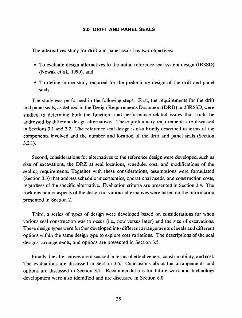
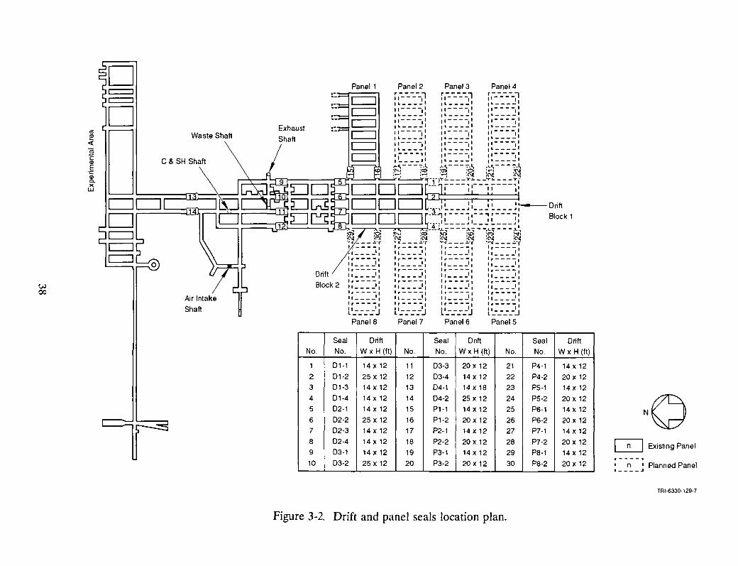
The reference seal system is defined in the Design Requirement Document (Bailey et
aI., 1992a), which is based largely on the design (see Figure 3-1) described in the IRSSD
(Nowak et al., 1990). The reference seals consist of monoliths and grouting for the short
term seals and emplaced WIPP-salt as the long-term seal. The short-term component of thedrift and panel seals will function as barriers to the migration of the hazardous material
from the waste disposal area during the operational phase. Additionally, the short-term seal
is considered necessary for confinement of the emplaced WIPP-salt until the long-term saltseal becomes adequately consolidated by creep closure of the host rock salt. The long-termseal is required to consolidate to 95 percent fractional density to achieve a state of
permeability to fluids comparable to the permeability of undisturbed host rock salt
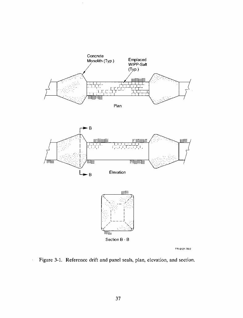
(Holcomb and Hannum, 1982; Holcomb and Shields, 1987). Figure 3-2 depicts the drift and
36
ConcreteMonolith (Typ.) Emplaced
/
WIPP-Salt(Typ.)
~----.-,6~
Plan
~B
Elevation
Section B - B
TRI-6121-79·Q
Figure 3-1. Reference drift and panel seals, plan, elevation, and section.
37
t:.
Drift
Block 2w00
Waste Shaft
Panel 1 Panel 2 Panel 3 Panel 4rl-_-_-_-_~ r;:.-_-_-_~ rl--------~
,, 1 L I 1" 1
I - - - -II I - - - -,I II - - - -I IL I L I 1" '
1- - - -II 1- - - -I' , I - - - -IIL I ,, , 1"----1
I - - - -I I I - - - -I' I I - - - -I I,, 1 1. , 1,, 1
I - - - -II I - - - -I I II - - - -I I&. 1 ,, 1 1" 1
- - - - , I I - - - -,I 11- - - -II1 ., ,, 1 1" •
...~ - - - "'_~ ... ~ - - - ",_~ .c~ - - - ",_~
~! i~:~ ;~!~ !~'-r~~----'f"1:-,:r~c=J-_:n:.O-.rB:rTl'r~::: ~~----~~::: ~f
c=J0 c=J -nl ~ ~ 1__ J ~ ~~ Driftr--lOr--lr-y--'l'----'--.,'----1 81 k1L-....J L-....J ~ ,I!... ~ 1__ J !... ~l OC
, ,:x:c; ;c,-~-J.....,---,.1..,--~L,---.t-I,:~ ig: ~ :~:~ :~:~ :~'I~ : : : :-~ 7~: : : :-~ '"";: :: :-~ .~~: : : :-f• I 'I I I 'I I I I I , I I
.'----1 ·'----1 r----I Ir----II I I, I I I, I I I I I ' I
1'---.1 1'---1' '---.' 1'---,111 __ --1 11 1 1 1 '1 I
1,----1 1,----1 ,----, 1,----1II II I I II 1 II ' I I I
"---1 1 1'---.1 '---.1 1'---.1" , " , 1 I 11 I
1'---.1 1'---1 1 '---i l 11'---,1
ll::::J ll::::J L'::::J ll_-_-_-_-JPanel 8 Panel 7 Panel 6 PanelS
Seal Drift Seal Drift Seal DriftNo. No. W x H (tt) No. No. W x H (ft) No. No. W x H (tt)
1 01-1 14 x 12 11 03-3 20 x 12 21 P4-1 14 x 12
2 01-2 25 x 12 12 03-4 14 x 12 22 P4-2 20 x 123 01-3 14 x 12 13 04-1 14 x 18 23 P5-1 14 x 12
4 01-4 14 x 12 14 04-2 25 x 12 24 P5-2 20 x 12 Ny5 02-1 14 x 12 15 PH 14 x 12 25 P6-1 14 x 126 02-2 25 x 12 16 P1-2 20 x 12 26 P6-2 20 x 127 02-3 14 x 12 17 P2-1 14 x 12 27 P7-1 14 x 128 02-4 14 x 12 18 P2-2 20 x 12 28 P7-2 20 x 12 0 Existing Panel9 03-1 14 x 12 19 P3-1 14 x 12 29 P8-1 14 x 12
03-2 25 x 12 P3-2 20 x 12 P8-2 20 x 12,----.
10 20 30 I n I Planned PanelI ____ J
TRI·6330·129·7
Figure 3-2. Drift and panel seals location plan.
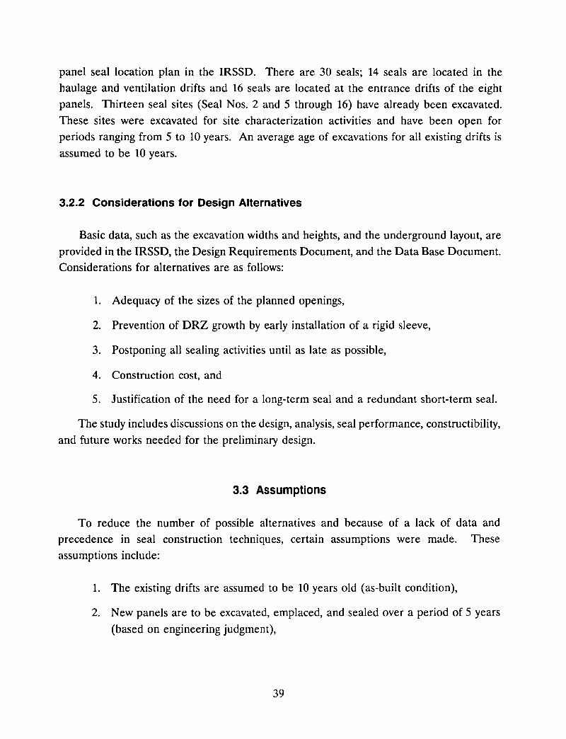
panel seal location plan in the IRSSD. There are 30 seals; 14 seals are located in thehaulage and ventilation drifts and 16 seals are located at the entrance drifts of the eightpanels. Thirteen seal sites (Seal Nos. 2 and 5 through 16) have already been excavated.
These sites were excavated for site characterization activities and have been open forperiods ranging from 5 to 10 years. An average age of excavations for all existing drifts is
assumed to be 10 years.
3.2.2 Considerations for Design Alternatives
Basic data, such as the excavation widths and heights, and the underground layout, are
provided in the IRSSD, the Design Requirements Document, and the Data Base Document.Considerations for alternatives are as follows:
1. Adequacy of the sizes of the planned openings,
2. Prevention of DRZ growth by early installation of a rigid sleeve,
3. Postponing all sealing activities until as late as possible,
4. Construction cost, and
5. Justification of the need for a long-term seal and a redundant short-term seal.
The study includes discussions on the design, analysis, seal performance, constructibility,
and future works needed for the preliminary design.
3.3 Assumptions
To reduce the number of possible alternatives and because of a lack of data andprecedence in seal construction techniques, certain assumptions were made. These
assumptions include:
1. The existing drifts are assumed to be 10 years old (as-built condition),
2. New panels are to be excavated, emplaced, and sealed over a period of 5 years
(based on engineering judgment),
39

3. For rigid sleeve installation, a salt thickness of 4 ft is provided between the
bottom of the rigid sleeve and the top of MB139 (Lin and Van Sambeek, 1992a).
The salt floor in the area of the rigid sleeve will be ramped up and down at a 10
percent maximum slope as required to provide this thickness. The salt bed under
the "rigid sleeve is to provide a cushion for uniform distribution of the liner
loading and to mitigate the upward thrust of MB139 during construction of the
rigid sleeve,
4. Airlocks are not required for personnel radiation safety at any drift and panel
seal locations,
5. The minimum clear opening for access to a repository panel is 14 x 12 ft with
no operational inconvenience, or 12 x 12 ft with some operational inconvenienc-
es,
6. Some form of grouting will be effective for plugging the disturbed rock around
the operational/short-term seals. However, the confidence for preventing
leakage by grouting is less than that for preventing flow by not allowing a
disturbed zone (DRZ in salt or damage in the marker bed) to develop,
7. Cost for the salt seal emplacement can be based on unit costs of nonshrink
cement-based grout ($1,800/cy) as an approximation for cost evaluation. The
unit cost of the mechanically compacted salt is assumed to be one-half of the cost
of the salt block scheme,
8. The length of the seal is assumed to be five times the width of the excavation.
The seal pattern is B-3B-B for monolith-salt-monolith, respectively, where B is
the width of excavation and is equal to the width of the drift, W, plus the depths
of excavation at the ribs for seal installation. This pattern is derived from an
engineering rule of thumb that the length of a rigid, solid seal shall be as long
as its width. The 3B length for the salt seal is based on one B minimum
permanent seal plus one B allowance at each side of the salt seal to minimize the
end effects of the monolith on the consolidation of the salt seal,
9. The volume of seal construction warrants custom-designed construction
equipment, as required, for excavation and erection of the seals, and
to. High-strength concrete, fiber-reinforced concrete, and nonshrink, cement-based
grout will be developed as required to supplement the concrete mixes provided
in the Data Base Document.
40
3.4 Evaluation Criteria
Various options of seal design will be evaluated for the advantages and disadvantageswithout weighting or ranking. Seal design alternatives are evaluated primarily byengineering judgment and such factors as:
• Seal effectiveness,
• Constructibility, and
• Rough order-of-magnitude construction cost.
3.5 Seal Design Types
Due to the constraints of the as-built conditions at WIPP, the waste panel layout, andrequirements for the waste emplacement operations, several design types must be considered
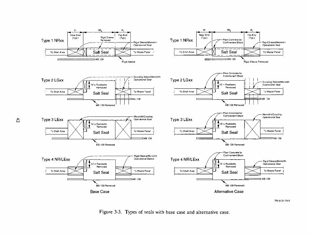
for the drift and panel seals. Four design types are established based on NOW vs. LATERconcepts and engineering requirements for the DRZ and MB139. Each design type consistsof two variations: a Base Case and an Alternative Case. Figure 3-3 shows two cases foreach design type. The Base Case seal has two identical concrete monoliths designed to
provide redundant operational seals. The Alternative Case seal has only one operationalseal and the near-end (drift side) monolith of the Base Case seal is replaced by a plainconcrete monolith for the purpose of confining the emplaced salt of the long-term seal. In
both cases, confidence for sealing during the operational phase can be bolstered by remedial
maintenance, ventilation, and monitoring measures at the access drift adjacent to the near
end monolith.
For convenience, a shorthand notation for the four design types is used in the text:
• NR = "NOW RIGID"
• LG = "LATER GROUT'
• LE = "LATER EXCAVATE"
• NR/LE = "NOW RIGID/LATER EXCAVATE"
41
Type 1 NRxx
8,
Far·End(Typ.)
Rigid Sleeve Rem::>ved
QRigid Sleeve/MonoirthOperational Seal
=:::-:::=-=-=c::--i-==To Waste Panel
C::::====::::liM8139
W
To Shaft AreaII'To Waste Panel
----;----"7";- Rigid Sleeve/MonohthOperational Seal
IM8139
8,
Near-End(Typ.)
J To Shaft AreaI
Type 1 NRxx
I II/I Grouting Sleeve/MonolithLL Operational Seal
ITo Waste Panel 1Salt Seal
c::::===L--c------Ij:::::F:F=PM8139
To Shaft Area
Type 2 LGxx
M8 139 Removed
To Waste Panel
;::
Monolith/GroutingOperational Seal
------...---
Salt Seal====L_~ -.JIL....__~===M8139
'. To Shaft Area',...,-------l
Type 3 LExx
/ Rigid Sleeve/Monoirth~ OperatIonal Seal
To Waste Panel -ISalt Seal
c::::===L_-..,. .J:===:::::lM8139
Type 4 NR/LExx
To Waste Panel
_-----------.,..-Rigld Sleeve/MonolithOperational Sleeve
c::::===L_-..,. J:===:::::lMB 139
Il To Shaft Area
Type 4 NR/LExx
M8 139 Removed M8 139 Removed
Base Case Alternative Case
TRI·6121·74·Q
Figure 3-3. Types of seals with base case and alternative case.
The "NOW RIGID" concept is centered around the assumption that a rigid sleeve is
installed at the future seal location immediately after excavation. Based on the results of
rock mechanics analyses in Section 2, a rigid sleeve installed as soon as possible after
excavation prevents some deformation of MB139 and arrests development of the DRZ. In
the absence of a timely placed rigid sleeve, the deformation in MB139 and the development
of the DRZ will likely compromise the seal system or at least require remedial activities to
achieve an adequate seal. The "LATER" concepts assume nothing is done to the
excavation until time for seal emplacement (i.e., a rigid sleeve is not immediately installed).
Therefore, remedial grouting and/or excavation of MB139 and the DRZ is considered
necessary for these types of seals. Excavation of MB139 may be required for the salt seal
region of NR seals also, as will be discussed below.
Each of the seal types will require technology to be developed for emplacing the salt
(whether crushed or as blocks) in the salt seal portion of the drift and panel seals.
3.5.1 Type 1 - NRxx Seal
The Type 1 - NR Seal is a "NOW RIGID" seal which uses a 5B pattern rigid sleeve
(Figure 3-3; for details, see Sketches SK-l, SK-2, and SK-3) to check and control the
development of the DRZ around the opening and deformation of MB139. The rigid sleeve
is installed in the seal area prior to further development of the drifts and panels. The
dimension B is established by the width of excavation in the seal. The term "xx" in NRxx
denotes the width of the passageway through the rigid sleeve; three sizes, 12 ft, 14 ft, and
20 ft, are considered. After waste emplacement, the middle section of the sleeve (length
= 3B) will be removed, the end sections (lB each) will be filled with concrete, and the
middle (3B) section will be filled with emplaced salt for development of a long-term seal.
The rigid sleeve is a steel shell and concrete composite structure similar to that
described in the WIPP alcove gas barrier (AGB) final design report (Lin and Van Sambeek,
1992b). The lining is made of ring segments which consist of four precast elements. Figure
3-4 depicts the basic construction sequence for a rigid sleeve ring segment. A more detailed
construction procedure is presented in the AGB final design report (Lin and Van Sambeek,
1992b). One edge of the roof element is modified to include a rigid sleeve removal key
block. Additionally, the connection details between two adjacent ring elements will provide
a bond breaker so the rigid sleeve can be removed with nominal prying force as shown inFigure 3-5.
43
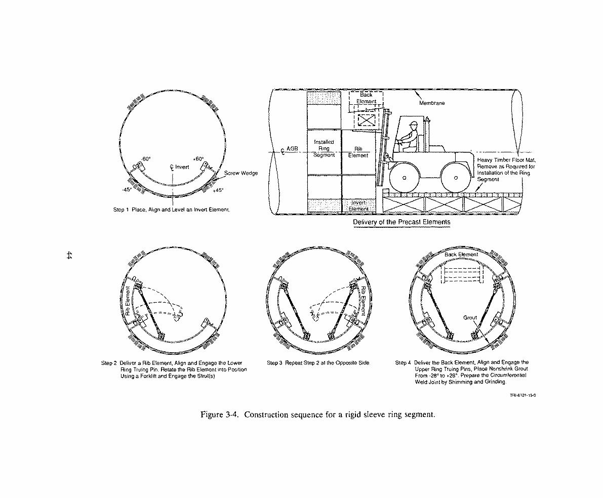
It Invert.Screw Wedge~
~~,.
~
~~=!=. ~ +45c
Step 1 Place, Align and Level an Invert Element.
InstalledRing
Segment-
Membrane
Delivery of the Precast Elements
Heavy Timber Floor Mat,Remove as Required forInstallation of the RingSegment
/
Step 2 Deliver a Rib Element, Align and Engage the LowerRing Truing Pin. Rotate the Rib Element into PositionUsing a Forklift and Engage the Strut(s).
Step 3 Repeat Step 2 at the Opposite Side. Step 4 DeHver the Back Element, Align and Engage theUpper Ring Truing Pins, Place Nonshrink GroutFrom -28° to +28°. Prepare the CircumferentialWeld Joint by Shimming and Grinding.
TRI·6121·1f>.O
Figure 3-4. Construction sequence for a rigid sleeve ring segment.

Bum-off the circumferential seal welds
2 Bum-off the longitudinal shell plate around the key block
3 Erect the back element support bent
4 Remove the key block
5 Bum-off the longitudinal seal weld
6 Pry loose and remove the rib element
7 Erect the back element support platform
8 Bum-off the longitudinal seal weld
9 Pry loose and remove the back element and the platform
10 Bum-off the longitudinal seal weld
11 Pry loose and remove the rib element
12 Pry loose and remove the invert element
Nole: The pull force T may be applied by a double actionhydraulic cylinders attached by a pair of eye bracketswelded to the shell plate
TAI·6121·7S·0
Figure 3-5. Rigid sleeve demolition sequence.
45
The rigid sleeves are sized according to a working stress design for an average linerloading of 2,150 psi, which approximates the lithostatic stress magnitude. A rock mechanics
study (see Section 2.3) indicated that the average liner loading approaches the lithostaticstress in 5 years and exceeds that value in later years. The maximum loading at the ends
of the rigid sleeve is about 3,500 psi. The NR12 sleeve is 21-in thick with a 1 3/4-in steel
shell. The NR14 sleeve has the same thickness, but with a 2 1/4-in steel shell. The NR20
sleeve is 33-in thick with a 3 1/4-in steel shell. The structure is expected to have a ductilemode of failure so ample warning will be given prior to any failure. Refined designcalculations will be necessary for selection of material strength and monolith configuration
at the design stage.
The monoliths are built within the IB segment at each end of the rigid sleeve. Figure3-6 illustrates a concept for construction of the cast-in-place (eIP) monolith at the drift side
of the seal. Two 3/8-in steel plate bulkheads serve dual functions as a gas barrier and as
the formwork for a prepacked concrete monolith. These steel plates are protected fromcorrosion by a 2-ft thick concrete covering. The solid core masonry wall is a construction
form for placement of the cast-in-place concrete. Prepacked concrete block is used to
minimize any concrete shrinkage problems.
The 3B (central) portion of the rigid sleeve is removed prior to construction of the saltseal. The construction scheme for the salt seal is similar to the one shown in Figure 3-7
except there is no further excavation required beyond the rigid sleeve. The lower portion
of the salt seal is placed in layers and mechanically compacted to at least 80 percentfractional density. The upper portion of the salt seal, approximately 10 ft high, uses
quarried-salt blocks and salt mortar and is built like a masonry block structure. The
concrete grout placed in the construction access protects the steel bulkhead in the outer
monolith from corrosion.
The DRZ in the salt around the monolith is expected to be healed so the monoliths can
act immediately as operational seals. The two monoliths will function as redundant
operational seals. The outer rigid sleeve may serve as the core structure for remedialgrouting of the DRZ if required. A rock mechanics calculation in Section 2 suggests that
the emplaced salt with 80 percent minimum fractional density may consolidate enough inabout 45 years to meet the requirement of the long-term seal. A more conservative
statement is that the emplaced salt is expected to consolidate adequately within the lOO-yeartime frame.
46
~.:..c:...,~~+ Solid CoreMasonry Wall
f;.:... , .. ,\...~!,-Salt Back Fill, I '.'
BMonolith
~A
:.:;. :.~.
3/8' PI.---.j.Bulkhead 1
® ®2'-0'
CIPCone.
<.;'..~:';.:_.........~ ..
Tie Rods .~ .',
®2'-0'
Shell Plateof Rigid Steelor GroutingSleeve
=ruotiooI.' ;-.3/8' PI.Bulkhead 2
Construction Sequence
Erect Masonry Wall as the Far Side Fonn
2 Install Bulkhead 1
3 Place Cast-in-Place (CIP) Concrete
4 Install Bulkhead 2, Ties and Prepacked Precast Blocks
5 Grout Monolith with Cement-Based Non-Shrink Grout
6 Fonn and Place CIP Concrete
Section A
TRI-6121·76·0
Figure 3-6. Cast-in-place monolith in a rigid sleeve or grouting sleeve.
47

p::z::Z::::z::::z::===r=_.-::.'_ _ _ . -_-.-_-_-~'=:z::===z::=::i:~
~-------~-- _.- -
Panel
WasteB
CIPMonolith
Far-EndMonolith
(see Fig. 3-6 forthe Cast-in
Place Monolith)
ExcavationBoundary
-----== ~=MB~CD
38
Salt seal
8
1
-- Near-EndMonolith
MB-139
Passageway
Rigid Sleeve orGrouting Sleeve
Construction Sequence
Place salt in optimum thickness layer and water content and mechanically compactedto 80% Maximum Density to the access opening level.
2 Install quarried-salt block dike and 3 place mechanically compacted salt in layersto about 10 ft. below the roof of the opening.
4 Place quarried-salt block and mortar salt seal.
5 Grout the construction access with nonshrink cement-based grout.
TRI·6121·7B-O
Figure 3-7. Construction scheme for long-term salt seal.
48
An unresolved concern is the deflection of MB139 beneath the salt seal region during
the consolidation period. As much as 20 percent room closure must occur before an 80
percent emplaced-density crushed salt is completely consolidated (5 to 10 percent room
closure could be required for quarried-salt blocks). Therefore, significant deflection and
fracturing of MB139 could occur in the salt seal region, despite continued restraint against
deflection in the monolith regions. This may necessitate removal of the marker bed before
salt emplacement or development of a special method for sequential rigid sleeve removal
with concurrent high-density salt emplacement (salt blocks) to reduce the amount of closure
and subsequent deflection of the marker bed.
3.5.2 Type 2 - LGxx Seal
The Type 2 - LG Seal is a "LATER GROUT' seal in which nothing is done to the
excavated opening until time for seal construction after waste emplacement. The seal uses
a BI-3B2-B1 pattern, where B1 is the width of the existing excavation at the monolith location
and B2 is the width of the excavation in the central portion where the salt seal is to be
constructed. The term "xx" in LGxx denotes the width of the initial passageway. Five sizes
(12 ft, 14 ft, 18 ft, 20 ft, and 25 ft) are considered for this type of seal.
After waste emplacement, the seal construction will begin with the erection of the
grouting sleeves at the monolith locations. The two grouting sleeves, each made of a B1 ft
long, 10 ft inside diameter steel shell, and cast-in-place concrete, are located 3B2 distance
apart (Figure 3-3; for details, see Sketch SK-4). The sleeve provides the resistance against
the pressure loading from the DRZ grouting. Grouting fans will be drilled through the shell
plate through which the DRZ will be grouted. When the DRZ grouting is completed, the
far-end monolith may be constructed according to the sequence shown in Figure 3-6.
The next step is to excavate the DRZ and MB139 which might have been fractured in
the middle 3B2 section. From the rock mechanics study in Section 2.2, it can be seen that
the DRZ extends about 3 ft horizontally into the ribs, about 5 to 10 ft above the roof, and
to the bottom of MB139. During the 5-year period when the panel is being developed and
emplaced, additional rock bolts may be needed at the roof of the drift for operational safety,
or there could be significant damage at clay seam G which is located about 9 ft above the
roof of the drift, as shown for example in Figure 2-7. It is assumed that during the salt seal
49

construction, the DRZ below clay seam G will be removed both for safety and for a
conservative design.
A DRZ excavation concept for the salt seal is shown in Figure 3-8. The excavation willbe done by a custom-made shearer, starting from the roof down to the bottom of MB139.The equipment will be designed to fit the lO-ft-diameter access through the outer grouting
sleeve. A roof support shield is required for personnel safety during excavation of the roof.
A placement scheme for the salt seal is shown in Figure 3-7.
3.5.3 Type 3 - LExx Seal
The Type 3 - LE Seal is a "LATER EXCAVATE" seal in which nothing is done to
the seal area until time for seal construction after waste emplacement. This seal also uses
a B-3B-B pattern, with B being the width of excavation at the monolith locations. The term
"xx" in LExx denotes the width of the initial passageway.
Five sizes (12 ft, 14 ft, 18 ft, 20 ft, and 25 ft) are considered for this type of seal. The
seal consists of two cast-in-place concrete monoliths at the ends and a salt seal in the center(Figure 3-3; for details, see Sketch SK-5). Prior to the seal construction, the DRZ aroundthe seal area and MB139 will be excavated.
Based on analysis, the DRZ extends into the stratigraphy as shown in Section 2.2, the
overexcavation extends about 10 ft above the roof, about 3 ft into the ribs, and to the
bottom of MB 139. The construction starts with DRZ removal similar to that shown in
Figure 3-8, but for the total length of 58. The far-end (waste side) monolith is placed with
steel plate bulkheads and cast-in-place concrete. An interface grouting system or
longitudinal membrane system is provided around the monolith for an operational seal.
Placement of the salt seal is similar to that of the Type 2 seal. The near-end (drift side)
monolith is built similar to the far-end (waste side) monolith.
3.5.4 Type 4 - NR/LE14 Seal
This NR/LE ("NOW RIGID/LATER EXCAVATE") seal combines the features of the
Type 1 rigid sleeves and the Type 3 overexcavation for the central salt seal at a later time.
It uses the B.-3B2-B, pattern described for Type 2 seals. Fourteen denotes the size of the
50

8Rigid Sleeve
Grouting Sleeve
Near-EndMonolith
Clay Seam G
Clay Seam E
38Salt Seal
DRZ Excavation Sequence
1. Construction berm to suit the roofsupport shield and the shearer.
2. Install the roof support shield. under thearea the rockbolts are to be removed.
3. Remove all rockbolts in the area tobe excavated.
4. Excavate the roof DRZ with a custommade shearer in slices. Repeat steps 2and 3 as required.
5. Remove the construction berms. asrequired, for invert excavation.
6. Excavate the invert.
Notes
1. For type 2 seal systems, the groutingsleeve and DRZ grouting shall becompleted prior to the DRZ excavation.
2. The roof support shield and the shearerfor DRZ excavation are to be custommade to suit the dimension of thegrouting sleeve.
8
Far-EndMonolith
38Waste Panel
TAI·6121·77·Q
Figure 3-8. DRZ excavation concept for salt seal.
51
initial passageway. Only one size is considered for this type.
The two rigid sleeves, each BI long, oval-shaped steel shell, and precast concrete, are
located 3B2 apart and are installed "NOW" (Figure 3-3; for details, see Sketch SK-6) prior
to further development of the drifts and panels. The rigid sleeve installation procedure is
similar to that of Type 1. At the time for salt seal construction, the concrete monoliths can
be built with the concept shown in Figure 3-6.
The central 3B2 portion of the seal will be overexcavated at a later time. The
excavation boundary is similar to that for the Type 3 seals and the excavation concept shown
in Figure 3-8. The construction scheme for the salt seal shown in Figure 3-7 could also be
used here.
3.6 Evaluation and Selection of Design Types
3.6.1 Evaluation of Design Types
The design types are discussed in terms of the following criteria: (1) effectiveness, (2)
constructibility, and (3) cost. No attempt is made in this study to rank the design types.
The construction cost evaluation is made in fourth quarter 1992 U.S. dollars. When
material cost data are not available, the unit cost is based by analogy to the cost of other
material available in the market. Some unit costs from the AGB final design report (Lin
and Van Sambeek, 1992b) are also used in the cost estimate.
The engineering quantities and an order-of-magnitude cost estimate for each design type
are presented in Appendix A. Table 3-1 tabulates the estimated unit cost of all seal designs.
For comparison purposes, all unit costs are normalized with respect to the cost of the NR 14
type. In general, the "NOW" rigid sleeve seals, NRxx, cost about twice that of the
"LATER" seals, LGxx or LExx. It is also noted that the unit cost of the seal increases
disproportionately to the size of the seal. For instance, the increase in size from 12 x 12
ft to 20 x 12 ft is about 1.67 times; however, the illcrease in unit cost is about three times
from NR12 to NR20, and two times from LG12 or LE12 to LG20 or LE20. The
considerations for "NOW" vs. "LATER" seals are summarized in Table 3-2. The features
and viability of the types of seals are discussed in Sections 3.6.1.1 through 3.6.1.4. However,
some of the assumptions made need to be verified for implementation in the design phase.
52

Due to the lack of practical data for cost and schedule for large-scale emplacement ofcrushed salt to the required 80 to 90 percent (or greater) fractional density, the comparisons
of "NOW" versus "LATER" salt seal construction are order-of-magnitude only in terms of
either cost or schedule. All seal types require salt emplacement, but the volume requiredvaries by the seal type.
Table 3-1. Order-of-Magnitude Unit Cost Estimates for Base Case and Alternative CaseSeal Types
Seal Base Case Normal ized(a) Alternative Normal ized(a)
~ Seal LO. Cost Cost Case Cost Cost
1 NR 12 $4,053,000 73% $3,425,000 61%
NR14 $5,587,000 100% $4,693,000 84%
NR 20 $12,472,000 223% $10,468,000 187%
2 LG 12 $1,886,000 34% $1,704,000 30%
LG 14 $2,379,000 42% $2,122,000 38%
LG 18 $3,044,000 54% $2,660,000 48%
LG 20 $4,041,000 72% $3,579,000 64%
LG 25 $5,841,000 105% $5,163,000 92%
3 LE 12 $2,535,000 45% $2,028,000 36%
LE 14 $3,236,000 58% $2,632,000 47%
LE 18 $4,156,000 74% $3,298,000 59%
LE 20 $5,401,000 97% $4,277,000 77%
LE 25 $7,760,000 139% $6,263,000 112%
4 NR/LE 14 $3,706,000 66% $2,812,000 50%
(a) Normalized with respect to base case cost of NR14 type.
3.6.1.1 TYPE 1 - NRxx SEAL
The Type 1 - NR Seal uses a rigid sleeve installed as soon as possible after excavation
to check and control the development of the DRZ around the opening and deformation of
MB139. In the operational phase, it can be expected that the monolith will be effectiveimmediately after installation since substantial healing of the salt DRZ will already have
53
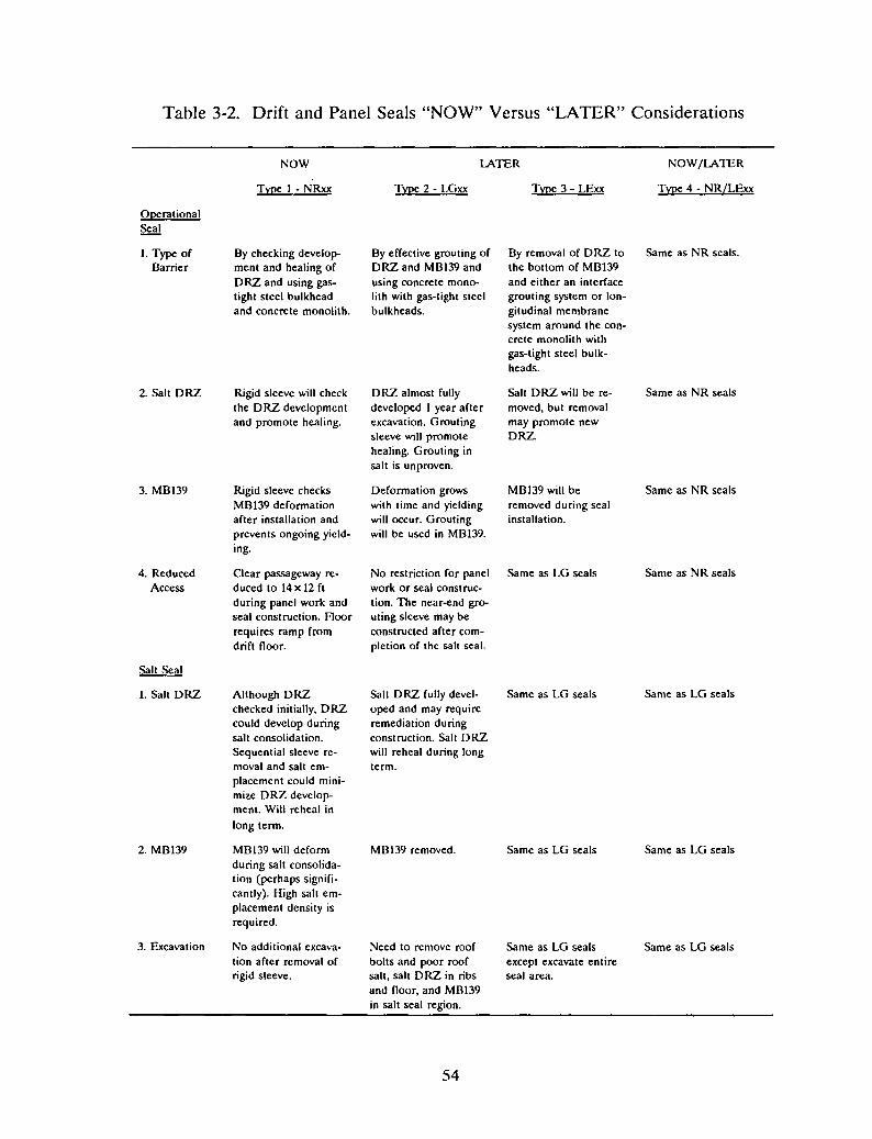
Table 3-2. Drift and Panel Seals "NOW" Versus "LATER" Considerations
NOW LATER NOW/LATER
Type 1 - NRxx Type 2 - LGxx Type 3 - LExx Type 4 - NR/LExx
OperationalSeal
1. Type of By checking develop- By effective grouting of By removal of DRZ to Same as NR seals.Barrier ment and healing of DRZ and MB139 and the bottom of MB139
DRZ and using gas- using concrete mona- and either an interfacetight steel bulkhead lith with gas-tight steel grouting system or lon-and concrete monolith. bulkheads. gitudinal membrane
system around the con-crete monolith withgas-tight steel bulk-heads.
2. Salt DRZ Rigid sleeve will check DRZ almost fully Salt DRZ will be re- Same as NR sealsthe DRZ development developed 1 year after moved, but removaland promote healing. excavation. Grouting may promote new
sleeve will promote DRZ.healing. Grouting insalt is unproven.
3. MB139 Rigid sleeve checks Deformation grows MB139 will be Same as NR sealsMB139 deformation with time and yielding removed during sealafter installation and will occur. Grouting installation.prevents ongoing yield- will be used in MB139.ing.
4. Reduced Clear passageway re- No restriction for panel Same as LG seals Same as NR sealsAccess duced to 14 x 12 ft work or seal construc-
during panel work and tion. The near-end gra-seal construction. Hoor uting sleeve may berequires ramp from constructed after com-drift floor. pletion of the salt seal.
Salt Seal
1. Salt DRZ Although DRZ Salt DRZ fully devel- Same as LG seals Same as LG sealschecked initially, DRZ oped and may requirecould develop during remediation duringsalt consolidation. construction. Salt DRZSequential sleeve re- will reheal during longmoval and salt em- term.placement could mini-mize DRZ develop-ment. Will reheal inlong term.
2. MBI39 MBl39 will deform MBI39 removed. Same as LG seals Same as LG sealsduring salt consolida-tion (perhaps signifi-cantly). High salt em-placement density isrequired.
3. Excavation No additional excava- Need to remove roof Same as LG seals Same as LG sealstion after removal of bolts and poor roof except excavate entirerigid sleeve. salt, salt DRZ in ribs seal area.
and floor, and MBl39in salt seal region.
54
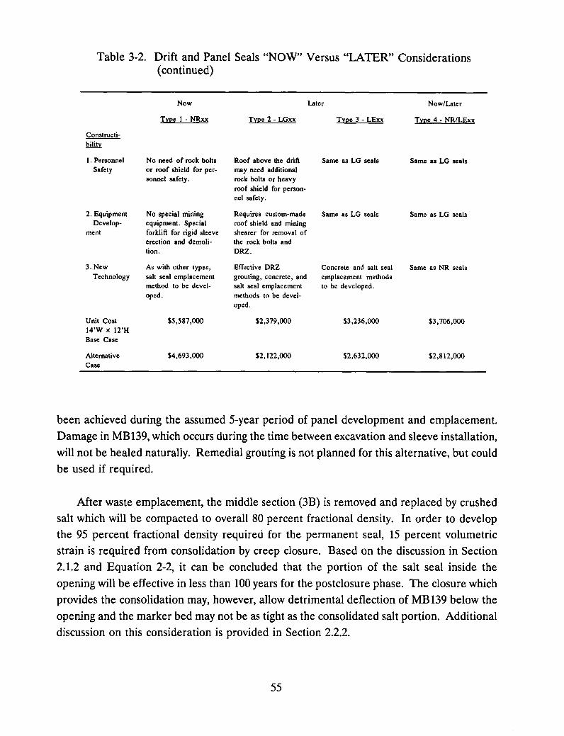
Table 3-2. Drift and Panel Seals "NOW" Versus "LATER" Considerations(continued)
Now Later Now/Later
Type 1- NRxx Type 2 - LGxx Type 3 - LExx Type 4 - NRlLExx
Constructi-bility
I . Personnel No need of rock bolts Roof above the drift Same as LG seals Same as LG sealsSafety or roof shield for per- may need additional
sonnel safety. rock bolts or heavyroof shield for person-nel safety.
2. Equipment No special mining Requires custom-made Same as LG seals Same as LG sealsDevelop- equipment. Special roof shield and mining
ment forklift for rigid sleeve shearer for removal oferection and demoli- the rock bolts andtion. DRZ.
3. New As with other types, Effective DRZ Concrete snd salt seal Same as NR sealsTechnology salt seal emplacement grouting, concrete, and emplacement methods
method to be devel- salt seal emplacement to be developed.oped. methods to be devel-
oped.
Unit Cost $5,587,000 $2,379,000 $3,236,000 $3,706,00014'W X l2'HBase Case
Alternative $4,693,000 $2,122,000 $2,632,000 $2,812,000Case
been achieved during the assumed 5-year period of panel development and emplacement.
Damage in MB139, which occurs during the time between excavation and sleeve installation,
will not be healed naturally. Remedial grouting is not planned for this alternative, but could
be used if required.
Mter waste emplacement, the middle section (3B) is removed and replaced by crushed
salt which will be compacted to overall 80 percent fractional density. In order to develop
the 95 percent fractional density required for the permanent seal, 15 percent volumetric
strain is required from consolidation by creep closure. Based on the discussion in Section
2.1.2 and Equation 2-2, it can be concluded that the portion of the salt seal inside the
opening will be effective in less than 100 years for the postclosure phase. The closure which
provides the consolidation may, however, allow detrimental deflection of MB139 below the
opening and the marker bed may not be as tight as the consolidated salt portion. Additional
discussion on this consideration is provided in Section 2.2.2.
55
No custom-made equipment or new technology is required for construction of this type.
Three sizes of NR type are considered in this study. The NR12 seal has the minimum
access of 12 X 12 ft considered here and would require a modification of the reference
design. The reduced access has an inherent disadvantage during development, operation,
and construction of the monoliths and salt seal after waste emplacement. The NR14 seal
accommodates a 14- x 12-ft opening for standard one-way access, while the NR20 seal
provides a 20- x 12-ft opening for two-way access. All three rigid sleeve seals require
ramping the access floor up and down (about 4 ft, 4.4 ft, and 6.6 ft for the NR12, NR14, and
NR20 seals, respectively; see Sketches SK-1, SK-2, and SK-3 in Appendix D). For the NR20
seal, the ramps and seal require a minimum length of 287 ft, which does not fit in the space
for the panel arrangement as required in the Design Requirement Document (Bailey et aI.,
1992a). Additionally, the NR20 seal would require a 3 1/4-in thick steel shell which presents
significant constructibility problems such as welding and handling.
The unit costs of the NR12, NR14, and NR20 seals are $4,053,000, $5,587,000, and
$12,472,000, respectively (see Table 3-1). The use of a smaller rigid sleeve, NR12, trades
off some operational handicaps for about 25 percent capital cost savings compared to the
cost for a NR14 seal. The use of a larger rigid sleeve, NR20, would cost more than twice
the NR14 seal. The Alternative Case, which has one operational seal at the far-end (waste
side), costs about 16 percent less in comparison with the Base Case, which has redundant
operational seals, one located at each end of the salt seal.
3.6.1.2 TYPE 2 - LGxx SEAL
For the Type 2 - LG seal, nothing is done to the excavated opening until time for seal
construction after waste emplacement. At the time of seal construction, a DRZ will have
developed around the opening, including significant deformation of MB139. Remedial
grouting is planned for this type of seal. Based on the assumptions made (Section 3.3),
grouting will be effective for plugging the DRZ and for the potentially fractured MB139.
However, these assumptions need to be verified by field demonstration.
After waste emplacement, operational seals are placed at each end of the 3B2-long salt
seal by first constructing the grouting sleeve followed by remedial grouting and placement
of a monolith barrier inside the rigid sleeve at the far-end of the salt seal. Then, the
opening for the salt seal is excavated to remove the salt DRZ and damaged MB139. The
opening will be filled with crushed salt compacted to an overall 80 percent fractional
56
density. Then, the near-end concrete monolith will be placed to confine the emplaced salt
for creep consolidation. The results of rock mechanics analysis in Section 2 suggests that
the salt will achieve the required density of 95 percent within 100 years. Therefore, it can
be concluded that the salt seal will be effective in the postclosure phase.
The Type 2 seal will require custom-made roof shields and an excavation shearer for
overexcavating the salt seal area. Also, the large volume of crushed salt in the salt seal
emplacement, whether by compacted salt or by quarried-salt blocks, will require new
technology. The excavation for installation of the salt seal in this type of seal is
handicapped by the reduced access through the near-end sleeve and by the need for possible
repairs or replacement of the heavy excavation equipment.
Table 3-1 shows that the cost of the Base Case LG seals with redundant operational
seals is about 42 percent of that of the NR seals. About 10 percent additional cost savings
are provided by the Alternative Case of the LG seal which has only one operational seal.
3.6.1.3 TYPE 3 - LExx SEAL
Like Type 2, the Type 3 - LE Seal is a "LATER" seal. Seal construction starts withDRZ removal (both salt and MB139) for the total length of 5B, where B is the width of
excavation. This is followed by constructing a large cast-in-place concrete monolith
operational seal at the far-end. The operational seal does not require effective grouting as
in a Type 2 seal; however, an elastomeric membrane is required at the concrete/salt
interface to assure that there is no leak-passage at the interface which is the most critical
item of the operational seal. Next, the salt seal is constructed similar to that of Type 2.
This type also requires a custom-made roof support shield and excavation shearer for the
construction. The large volume of salt emplacement to 80 percent overall fractional density
may require new technology to be developed. However, there is no access limitation to
hinder the operation of the heavy excavation equipment because the near-end concrete
monolith may be placed after completion of the salt seal emplacement.
Table 3-1 shows that the unit cost of the Type 3 seal is about 58 percent of the cost of
a Type 1 seal, and is about one-third more than Type 2 for the Base Case with the
redundant operational seal. For the Alternative Case with only one operational seal, the
unit cost is about 80 percent of that of the Base Case.
57
3.6.1.4 TYPE 4 - NR/LE14 SEAL
This design type combines features from Types 1 and 3 and subsequently inherits some
of the advantages and disadvantages from these two types. As in the case of Type 1, the
monolith operational seal will be effective immediately after installation since DRZ
development is under control. Construction of the salt seal is similar to that of Type 3. The
emplaced salt will be consolidated to the required 95 percent fractional density in 100 years
or less, which provides an effective long-term seal.
This type may also require custom-made equipment to excavate the large volume of salt.
Reduced access through the near-end sleeve may hinder the operation of the heavy
excavation equipment.
Table 3-1 shows that the unit cost of the Type 4 seal is about 66 percent of the cost of
Type 1 seal for the Base Case with redundant operational seals. For the Alternative Case
with only one operational seal, the unit cost is about one-quarter less than the Base Case.
3.6.2 Seal Type Selection and Combination
3.6.2.1 SELECTION BASIS FOR SEALS LOCATED IN EXISTING EXCAVATIONS
There are 13 seal sites that have already been excavated (see Figure 3-1 for seal
locations). The excavation sizes vary from 14 X 12 ft to 25 X 12 ft. The existing sizes and
the site conditions will limit the choice of design options. The "NOW" seals, NRxx type,
are not applicable to existing excavations.
From the rock mechanics study (Section 2.2), it can be seen that within 1 year after
creating a rectangular-shaped excavation, the damaged zone around the excavation is almost
completely developed. However, the severity of damage of the DRZ in MB139 continues
to increase with time. For larger excavations (25 X 12 ft), yielding in the marker bed is
possible within the first year after excavation and can actually be observed at the WIPP.
In this study, an average age of excavations for all existing drifts is assumed to be 10 years.
By then, the DRZ around the excavation is expected to be fully developed, and MB139 will
likely have been fractured. In order to provide an effective seal design, only "LATER"
seals (Type 2 - LGxx and Type 3 - LExx) can be selected for the existing excavations, which
include Seal No.2 and Seal Nos. 5 through 16.
58
The lengths of the "LATER" seals, LGxx and LExx types, are not restricted by thelayout of the waste panel. The unit cost for "LATER"-type seals is about one-half or lessthe cost of "NOW"-type seals of similar size. However, the LGxx seals are viable only if
the grouting for DRZ and damaged MB139 is effective for an operational seal.
3.6.2.2 SELECTION BASIS FOR SEALS LOCATED IN NEW EXCAVATIONS
From the results of the rock mechanics study (see Section 2), it can be shown that when
a rigid structure, such as a rigid sleeve, is emplaced in salt, it will arrest development of the
DRZ around the opening and induce back pressure on the salt to promote healing of theDRZ. The rigid structure will also stop further deformation of MB139 so long as the linerremains in place. Since MB139 does not have the self-healing characteristic of the salt, itis essential to minimize damage to MB139. The effectiveness of the salt seal is assured byinitial compaction of the salt to 80 percent, or more, overall fractional density.
The choice of sizes for NR type seals, however, is limited to NR14 and NR12 by the
existing layout dimensions. The rigid sleeves for the NRxx type of seal need to be installed
immediately after excavation for assurance of the effectiveness of the operational seal. TheBase Case seals of NRxx type are handicapped by restricted access through the near-end(drift side) sleeves for construction of the far-end (waste side) monolith and emplacement
of the salt seal.
If nothing is done to the newly excavated opening until time for seal construction after
waste emplacement, then Type 2 - LGxx and Type 3 - LExx seals are the only seal types
that can be used for Seal Nos. 1, 3, 4, and Seal Nos. 17 through 30.
A Type 4 - NR/LE14 seal, which combines the features of Types 1 and 3, can also be
considered for all new excavations.
3.6.2.3 SEAL COMBINATION OF DESIGN ALTERNATIVES
From the selection basis elucidated in the previous sections, LG or LE type seals areneeded in the existing excavations, while seals in the new excavations could be either a NR,
LG, LE or NR/LE type. Theoretically, there are a very large number of designcombinations when all options are considered. In order to get a rough order-of-magnitude
59
cost estimate of the whole drift and panel seals for the WIPP sealing program, four seal
combinations are postulated (see Table 3-3). For each seal combination, a cost estimate ismade for the Base Case and Alternative Case designs.
The Base ~ase design uses the IRSSD (Nowak et aI., 1990) concept providing redundantoperational seals. The Alternative Case design has only one operational seal placed at the
far-end (waste side) and provides a plain concrete monolith inside the existing drift for thepurpose of confining the near-end (drift side) of the emplaced salt. At a waste panel, thereis no need of two-way traffic in the panel drift and reduction in the cross-sectional area haslittle impact on the ventilation requirement. Therefore, a pair of 14-ft and 12-ft panelaccesses seem to be adequate for the construction and operation of the panel. Combina
tions will be developed to determine the potential cost saving by downsizing the panelaccesses from 20 ft and 14 ft to 14 ft and 12 ft.
Seal Combination 1 maximizes the use of "NOW RIGID," Type 1 Seals by selectingNR14 seals for all new excavations. In the existing drifts, the "LATER EXCAVATE," Type3 - LExx seals are used. This combination does not depend on grouting for an operational
seal. Seal Combination 2 uses "LATER GROUT," Type 2 - LGxx seals at all 30 seallocations. Seal Combination 3 uses "LATER EXCAVATE," Type 3 - LExx seals at all 30
seal locations. Seal Combination 4 uses the "NR/LE" concept for new excavations. In the
existing drifts, the "LATER EXCAVATE," Type 3 - LExx seals are used.
3.6.2.4 ROUGH ORDER-Of-MAGNITUDE COST ESTIMATE
Herein, rough-order-of-magnitude costs imply standard construction industry estimates
of ±50 percent.
3.6.2.4.1 Unit Cost of Seals
The engineering quantities and order-of-magnitude cost estimate for the unit cost ofType 1, 2, 3, and 4 seals are shown in Tables A-I through A-4 in Appendix A, and
summarized in Table 3-1.
60
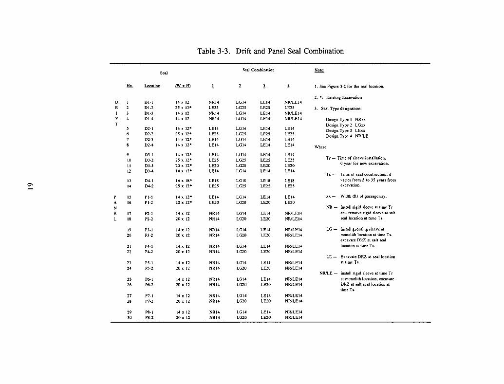
Table 3-3. Drift and Panel Seal Combination
Seal Combination Note:Seal
No. Location ~ ! ~ l ~ I. See Figure 3-2 for the seal location.
2.·: Existing ExcavationD 1 DI-I 14 x 12 NR14 LG14 LE14 NR/LEI4R 2 DI-2 25 x 12" LE25 LG25 LE25 LE25 3. Seal Type designation:1 3 DI-3 14 x 12 NRI4 LGI4 LEI4 NR/LEI4F 4 DI-4 14 x 12 NRI4 LGl4 LEI4 NR/LEI4 Design Type I NRxxT Design Type 2 LGxx
5 02-1 14 x 12" LE14 LGl4 LEI4 LEI4 Design Type 3 LExx6 02-2 25 x 12" LE25 LG25 LE25 LE25 Design Type 4 NRILE7 D2-3 14 x 12" LE14 LG14 LEI4 LEI48 D2-4 14 x 12" LEI4 LG14 LE14 LEI4 Where:
9 03-1 14 x 12" LEI4 LGI4 LEI4 LEI410 D3-2 25 x 12" LE25 LG25 LE25 LE25 Tr - Time of sleeve installation.
11 D3-3 20 x 12" LE20 LG20 LE20 LE20o year for new excavation.
12 D3-4 14 x 12" LEI4 LGl4 LEI4 LEI4Ts - Time of seal construction; it
13 04-1 14 x Ill" LE18 LGIS LEIS LEI8 varies from 5 to 35 years from0\ 14 D4-2 25 x 12" LE25 LG25 LE25 LE25 excavation.......
P 15 PI-I 14 x 12" LEI4 LG14 LEI4 LEI4 xx- Width (ft) of passageway.
A 16 PI-2 20 x 12" LF.20 LG20 LE20 LE20N NR- Install rigid sleeve at time Tr
E 17 P2-1 14 x 12 NRI4 LGl4 LE14 NR/LEI4 and remove rigid sleeve at salt
L 18 P2-2 20 x 12 NRI4 LG20 LE20 NR/LEI4 seal location at time Ts.
19 P3-1 14 x 12 NRI4 LG14 LEI4 NR/LEI4 LG- Install grouting sleeve at
20 P3-2 20 x 12 NRI4 LG20 LE20 NR/LEI4 monolith location at time T5:
excavate DRZ at salt seal
21 P4-1 14 x 12 NRI4 LG14 LEI4 NR/LEI4 location at time Ts.
22 P4-2 20 x 12 NR14 LG20 LE20 NR/LEI4LE- Excavate DRZ at seal location
23 P5-1 14 x 12 NRI4 LGI4 LEI4 NR/LEI4 at time Ts.
24 P5-2 20 x 12 NRI4 LG20 LE20 NR/LEI4NR/LE - Install rigid sleeve at time Tr
25 P6-1 14 x 12 NRI4 LG14 LE14 NR/LEI4 at monolith location. excavate
26 P6-2 20 x 12 NRI4 LG20 LE20 NR/LEI4 ORZ at salt seal location attimeTs.
27 P7-1 14 x 12 NRI4 LGI4 LEI4 NRILE14
28 P7-2 20 x 12 NR14 LG20 LE20 NR/LEI4
29 PS-1 14 x 12 NRI4 LG14 LE14 NR/LEI4
30 PS-2 20 x 12 NRI4 LG20 LE20 NR/LEI4

3.6.2.4.2 Total Estimated Capital Cost
The total order-of-magnitude capital cost for the WIPP drift and panel seals associatedwith the seal Combinations 1 through 4 are obtained by summation of the product of thenumber of seal type and the corresponding unit cost. Cost estimates for each individualcombination are tabulated in Tables A-5 through A-II in Appendix A. Table 3-4 shows the
summary of the order-of-magnitude cost evaluation for all seal combinations.
The total cost ranges from a maximum of $160,400,000 for the Base Case of sealCombination 1 to a minimum of $76,400,000 for the Alternative Case of seal Combination
2A (see Table 3-4). If there is no need for the redundant operational seal, the AlternativeCase has a cost about 20 to 25 percent less than the Base Case. Therefore, eliminating oneof the two operational seals warrants further investigation in the preliminary design of the
WIPP drift and panel seals. For the Alternative Case, the order-of-magnitude total cost is
about $100 million + 30 percent. Downsizing the access widths reduces the total cost about15 percent compared to the Base Case. No specific combination of seals seems to havesignificant cost advantages over other combinations of seals.
Table 3-4. Summary of Rough Order-of-Magnitude Cost Evaluation
Seal Base Case Alternative CaseCombination Total Amount Total AmountNo.
1 $160,387,000 $132,487,000
lA(a) $149,648,000 $123,608,000
2 $100,833,000 $89,647,0002A(a) $85,753,000 $76,390,000
3 $135,579,000 $108,960,0003A(a) $115,516,000 $93,215,000
4 $123,415,000 $100,508,000
(a) Panel seals at new excavation with passageway width downsized from 20 ft to14 ft and 14 ft to 12 ft.
62
3.7 Conclusion
Since about one-half of the seal sites are in existing drifts, both "NOW" and "LATER"types of seals may be used. The "NOW" seal uses rigid sleeves in yet to be excavated driftsto check the growth of DRZ and provide backpressure for healing the DRZ in salt. It may
provide the most effective operational seal among those types studied, particularly if aneffective grouting procedure cannot be developed. NR seals have a constructibility problemif the clear opening through the seal must be larger than 14 x 12 ft or 12 x 12 ft. The unitcost of the "NOW" sleeve is about twice that of the "LATER" sleeves.
Two types of seals, LGxx and LExx, have been studied for the "LATER" seal to be
installed in the drift opening after waste emplacement. The LGxx seals use grouting of theDRZ, especially the damage in MB139, for an operational seal, but such an effective
grouting procedure is yet to be developed and demonstrated. Both LG and LE types of the"LATER" seals use excavation to remove the salt DRZ and the damaged MB139 for theemplacement of the permanent salt seal component. The rock mechanics study showed thatthe effectiveness of these salt seals can be achieved if the emplaced salt is compacted to anoverall fractional density of 80 percent or more. Both types of the "LATER" seal willrequire custom-made equipment for excavation.
MB139 is not protected after removal of the rigid liner from the salt seal portion of NRtype seals during salt consolidation. A combination of NR-type operational seals and LE
type salt seals (with removal of the MB139) may solve this problem. Other variations or
methods of salt emplacement could also provide acceptable control of the marker bedduring the salt consolidation period.
Two cases (Base Case and Alternative Case) of seals have been studied. The Base Case
uses the monolith at each end of the salt seal as redundant operational seals. TheAlternative Case provides a single operational seal at the far-end (waste side) monolith anduses a plain concrete block at the near-end (drift side) monolith for confinement of the saltseal. The unit cost of the Alternative Case is about one-fifth less than that of the Base
Case. The need of a redundant operational seal has not been resolved. Therefore, theAlternative Case warrants further refinement in the preliminary design of the WIPP drift
and panel seals.
The cost estimate for this study is a rough order-of-magnitude in that there is noprecedent for this type of underground work under the rigid control of NQA-l requirements.
63
The unit cost for the salt seal emplacement is based on an estimate for a comparable
nonshrink, cement-based structure.
For the Alternative Case, the total cost for the WIPP drift and panel seals may rangefrom about $130 million for seal Combination 1 to about $90 million for seal Combination
2. About 15 percent cost savings may be realized if the panel seals at the new excavations(Panel Nos. 2 through 8) uses the minimum size of 12 x 12 ft for passageway. This
refinement would require study of the construction and operation methods for the wastepanel, which are not in the scope of this study. From this study, it can be concluded thatthe rough order-of-magnitude cost for the WIPP drift and panel seals is about $100 million.
64
4.0 SHAFT SEALS
Four seal subsystems are included in the shaft sealing system. Because different
materials are needed to meet the sealing requirements in each subsystem, a study of
alternative materials comprised a large part of the shaft seals alternative study. The
alternatives study proceeded in the following manner.
First, the purpose and requirements for the four seal subsystems were identified and are
described in Sections 4.1 and 4.2. The DRD and IRSSD formed the basis for the reference
design and materials, which includes concrete, bentonite, crushed salt, and compressed-salt
blocks as the seal components.
Second, alternative materials were identified: asphalt or bitumen, a chemical seal
material, and quarried-salt blocks. Performance of the alternative and reference materials
was based on the rock mechanics analyses results (see Section 2.), literature citations, and
manufacturers' information.
Third, eight material configurations in the shaft seal subsystems were evaluated in terms
of sealing effectiveness, constructibility, and cost. Effectiveness became a dominant concernin the lower shaft seals because not all materials could be shown to be capable of meetingthe design requirements presented in the DRD.
Finally, conclusions and recommendations on the shaft seal system alternatives were
formulated and requirements for future work identified.
4.1 Purpose
Sealing functions for the WIPP shaft seals are to be carried out by a combination of
short-term and long-term seals (Nowak et al., 1990). Short-term seals provide the initial
sealing functions necessary until the long-term, crushed-salt seal component becomes
adequately consolidated by creep closure of the shafts.
The design lifetime of short-term seal barriers is 100 years. The main functions of
short-term seal barriers are: (1) prevent water-brine seepage into the area of long-termseals, (2) prevent gas migration from waste repository, and (3) confine the long-term seal
65

during its reconsolidation period. In the reference design, the short-term seals consist of
swelling clay and concrete. The swelling clay components are intended to limit water inflow
from above to protect the crushed salt from saturation with brine. The concrete
components provide some flow resistance to help control the release of possible gas
generation in the waste disposal area. They also provide physical containment for the
swelling clay and consolidating crushed-salt materials.
The design of long-term seal components is based on the DRD and the DBD (Bailey
et aI., 1992a; 1992b) and the IRSSD by Nowak et aI. (1990). The fundamental strategy in
the design of the long-term seal barriers is two-fold.
1. Use the same material for the seal as found in the repository (Le., WIPP salt).
2. Maximize the length of the shaft section (seal barrier) with WIPP salt in the
Salado Formation.
In the reference design, it is assumed that within 100 years, the creep closure of the shaft
will reconsolidate the emplaced salt to nearly the same sealing capacity as the host rock.
Two forms of salt material were considered for use in the long-term barriers in the
reference design, WIPP crushed salt and compressed-salt blocks made of WIPP crushed salt.
Little compositional difference is expected between the emplaced seal and the surrounding
host rock salt from which it was mined. The salt seals are therefore expected to be
mechanically and chemically stable in the WIPP environment for the required lifetime of
the seal system. Design alternatives, including different types of sealing materials, are
evaluated in this study to provide a comparison of various design options for effectiveness
and relative cost. Alternatives for short-term components are considered and different ways
of emplacing WIPP salt in the shaft are evaluated.
4.2 ReqUirements for the Shaft Seals
The shaft sealing subsystems provide the long-term sealing capability to meet EPA
regulatory requirements for the postclosure period in terms of preventing excessive release
of waste materials to the accessible environment. The shaft seals also control the down flow
of brine from the water-bearing zones, separate aquifers, and provide near-surface seals to
meet State of New Mexico regulations. Shaft seals are not designed to prevent brine inflow
from the salt in the Salado Formation. Calculations show that brine inflow from the
surrounding salt will not interfere enough to prohibit consolidation of the emplaced salt seal
66

components (Nowak et aI., 1990). The four WIPP shafts are the Salt Handling Shaft, the
Waste Shaft, the Air Intake Shaft, and the Exhaust Shaft. All are partially lined and contain
existing concrete structures (keys).
Seals are to be installed in each of the four shafts at selected locations in the lower
shaft, the upper shaft, the water-bearing zone, and near-surface. Shaft seals will be
emplaced starting at the bottom of the shaft and proceeding upward toward the top (see
Figure 4-1).
4.2.1 Lower Shaft Seals
The lower shaft sealing subsystem is located within the Salado Formation in each of the four
shafts (see Figure 4-1). The lower shaft sealing subsystem consists of seals within the Salado
Formation, including seals below the Rustler/Salado Formations contact zone. The seals consist
of short- and long-term components. A column of emplaced salt in the lower shaft seal system
is the primary long-term barrier to the escape of waste materials from the repository horizon.
The long-term seals control fluid flow and waste release for the purpose of meeting EPA
requirements during the postclosure phase. In the reference design, it was estimated that the
emplaced salt components of these seals would be sufficiently consolidated by creep closure
within 100 years after emplacement to meet the long-term sealing functional requirements
(Nowak et al., 1990). The DRZ at these seal locations is expected to be sufficiently healed as
a result of the back pressure from the consolidating emplaced salt to meet the long-term sealing
functional requirements within the same time interval of 100 years. Short-term seals in the
lower shaft are intended to provide short-term waste isolation, gas flow control, and redundant
water inflow control for approximately 100 years after emplacement.
Preliminary short-term criteria from the DRD for the lower-shaft seals (Bailey et al., 1992a)
are:
1. Waste release rate to be determined from calculations,
2. Withstand calculated loads from gas pressure, lithostatic loading, and swelling clay,
3. Contain swelling clay and crushed-salt materials,
4. Provide seal structure permeability of 1 x 10⁻⁷ darcy (1 x 10-19 m2) or less, and
67
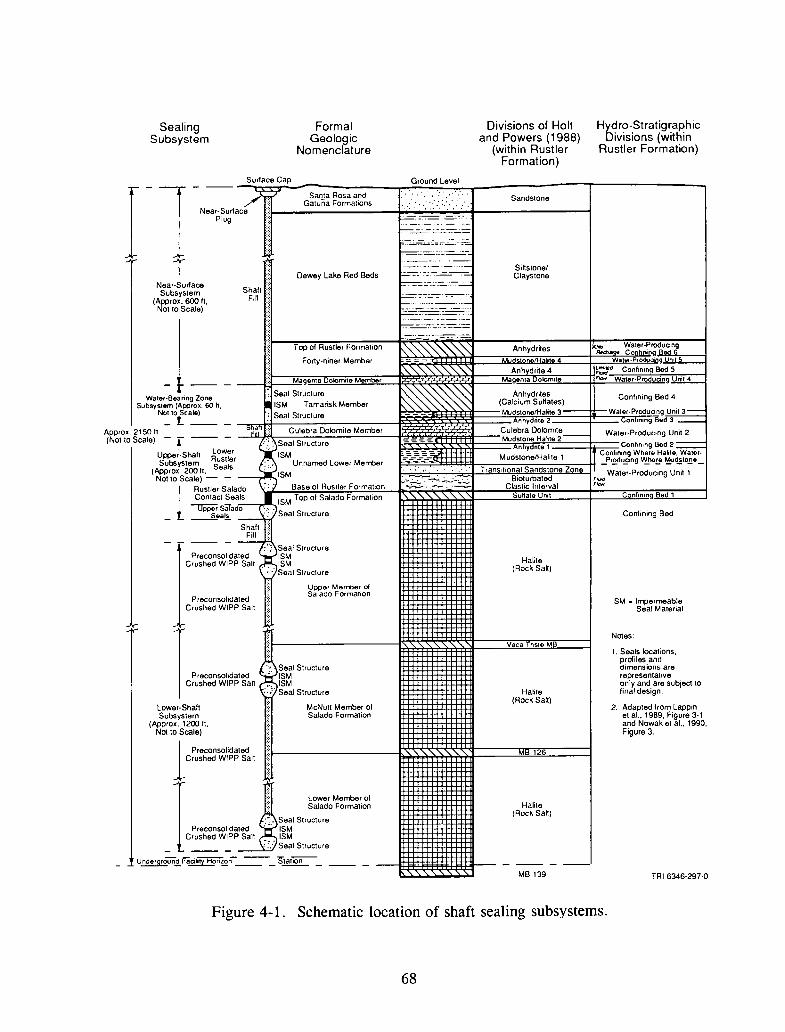
Confining Bed
Hydro-StratigraphicDivisions (within
Rustler Formation)
SittstonelClaystone
Halite(Rock Salt)
Sandstone
Anhydrites Confining Bed 4(Calcium SuHates)MudstonetHahte 3 Water-Producing Unit3-
nhydnte 2 ,Con lnln9 Bed 3 _
~~:~~~~~~it;_ Water-Producing Unit 2nhydnte 1 Conflnlng Bed.2 :::;;:==
TConfimng WherE! Ha~t8. Wator·Mudstone/Halite 1 Produang Whore Pv1udstone
Tron Itional Sandston~ 7~n~ Wat;'-Produc~ng-u~~ ~ -Bioturbated Ftaa
Clastic Interval F/ctIt
utfalo Urut Cn nflning..B"'o"'d""1__--'
Divisions of Holtand Powers (1988)
(within RustlerFormation)
7:z. 1.:z.:z..:z::j
Ground Level
._.. _--_..-"'-.'7.C,.,".-:-.:=.. .....==~~::=:.==
==::;=:~.,'- ... _.__ ....-~._=::~ .••..:..:-=~-.:;:~::~~~~
~'"'"'""'''''""" Anhydr~es x:.,,_ ~~~o::.,~u~n2W3 ·P,odu 'n9 nl
Dewey Lake Red Beds
FormalGeologic
Nomenclature
Top of Rustler Formation
Forty-niner Member
~ Seal StructureISM Tamarisk Member
: Seal Structure
Surtace Cap
ShallFill
~=M!92!~~~!!:!~~:c:=ll~'\.,'\..~'~·","~.'\..'~,'\..~'~·",'\..~·t:::=::::J~A~n~hvicd]r~~e~4~L==it~::· Confining Bed 5__--£l-!-_-"M"'agen18 olomite Member Magenta olomite Flew Water·Prod 'ng.l!!!i!..i...-
~
- --- ~ Santa Rosa and/"" [I Gatuna Formations ' ..,':", ..
Near-Surtace "'~-----------40;';';-;';';"',;",;,";'~------------lPlug ""=~=-:::=
=---:-~-.:'=.c:;=
'.7~';:::-~,:~.~-=·.':;;;'
='=;".=-
Near-SurtaceSubsystem
(Approx. 600 ft,Not to Scale)
SealingSubsystem
11J-Water·Bearing Zone
Subsystem (Approx. 60 h.Not to Scale)_t_
Approx. 2150 It ~;I ? Culebra Dolomite Member
(Not to Scale) - f --- - ~.:~":Seal StructureUpper.Shall Lower ISMSubsystem Rustler - U d L M rr/)
(Approx. 200 ft. Seals : '.- nname ower e erNot to Scale) - - . , ISM
tRustier Salado \:,,) Base of Rustler FormationContact Seals .I ISM Top of Salado FormatIOn
opp~~~~.a:~o': /:;Seal StructureShall ,::Fill:
: ~'.'" Seal StrudurePreconsol,dated ISM
Crushed WIPP Salt . ISM... : Seal Structure
ISM. ImpermeableSeal Material
1. Seals locations.profiles anddimensions arerepresentativeonly and are subject tofinal design.
2. Adapted from Lappinet al.. 1989, Figure 3-1and Nowak et aI., 1990,Figure 3.
Notes:
MR 126
Halite(Rock Salt)
Halite(RockSatt)
Vaca nsle M
Uppor Merrber ofSalado Formation
McNutt Member ofSalado Formation
Seal StructureISM
". ISM:.,:' Seal Structure
PreconsohdaledCrushed WIPP Salt
IC,;:';:""'i::I;'~"Lower-ShaftSubsystem
(Approx. 1200 ft.Not to Scale)
1PreconsolidatedCrushed WIPP Salt
1 J::: Lower Member of::= Salado Formation
.~. Seal StructurePreconsol,dated :.. ISM
Crushed WIPP Salt ISM;:.: Seal Structure
MB 139 TRI-6346-297-0
Figure 4-1. Schematic location of shaft sealing subsystems.
68
5. Provide permeability of less than 2 x 10⁻⁷ darcy (2 x 10-19 m2) in the DRZ and the
interface between the seal structure and the host rock.
Preliminary long-term criteria from the DRD for the lower-shaft seals (Bailey et al., 1992a)
are:
1. Waste release rates to be provided from calculations,
2. Crushed salt to be reconsolidated by creep closure to provide permeability of 1 x
10-8 darcy (1 x 10-20 m2), and
3. Reloading from creep closure will restore DRZ permeability to 1 x 10⁻⁸ darcy, (l
x 10-20 m2).
4.2.2 Upper-Shaft Seals
The upper-shaft seals consist of components in the Lower Rustler, the Rustler/Salado
contact, and the Upper Salado (see Figure 4-1). Multiple seals are located in the upper shaft
for redundancy. Because saturation by brine may inhibit the consolidation of emplaced salt in
the lower-shaft seal, control of brine inflow from the Rustler Formation is the principal
determinant of performance requirements for the upper-shaft seal system. The upper-shaft seals
are designed to limit groundwater flow at least until reconsolidation of the emplaced salt in the
lower shaft is sufficient for sealing effectiveness.
Preliminary criteria from the DRD for the upper-shaft seals (Bailey et al., 1992a) are:
1. Maximum allowable water flow rate from Rustler Formation to be 35 ff (l m3) per
year,
2. Withstand calculated loads from gas pressure, lithostatic, shaft fill loading, and water
pressure,
3. Contain swelling clay material loads,
4. The seal structure to provide a barrier to fluid flow equivalent to permeability of 2
x 10-7 darcy (2 x 10-19 m2),
5. An impermeable seal material to provide a permeability of 1 x 10⁻⁷ darcy (1 x 10-19
m2) or less after saturation with water, and
69
6. Provide permeability of less than 2 x H)"7 darcy (2 x 10-19 m2) in the DRZ and the
interface between the seal structure and the host rock.
4.2.3 Water-Bearing Zone Seals
The water-bearing zone sealing subsystem separates the Culebra and Magenta aquifers.
Components consist of seal structures, swelling clay, and grout placed in the DRZ at seal
locations. The components separate the aquifers by containing the swelling clay, which provides
resistance to flow.
The water-bearing zone components are located in the Tamarisk Member between the
Magenta Dolomite Member and the Culebra Dolomite Member (see Figure 4-1).
Preliminary criteria from the DRD for the water-bearing zone seals (Bailey et aI., 1992a)
are:
1. Groundwater flow between aquifers to be permanently separated.
2. Withstand calculated loads from lithostatic and shaft fill. Contain swelling clay
material loads.
3. Barrier to fluid flow equivalent to permeability 2 x 10⁻⁷ darcy (2 x 10-19 m2.)
4. Exhibit swelling clay permeability of 1 x 10⁻⁷ darcy (1 X 10-19 m2) after saturation
with water.
5. Grouting will achieve a permeability in the DRZ and interface between the seal
structure and host rock equivalent to 2 X 10⁻⁷ darcy (2 X 10-19 m2).
4.2.4 Near-SUrface Shaft Seals
Near-surface seals are placed as final cover to the shaft after all other components of the
shaft sealing systems and shaft-filling material have been emplaced. They are protective covers
on the top of the shaft and for that part of the shaft immediately below ground surface level.
The near-surface shaft seals present markers and keep surface water out of the shaft. The near
surface portion of the shaft is filled with earthen material. The near-surface sealing components
are located at the top of each of the four shafts (see Figure 4-1).
70
Preliminary criteria from the DRD for the near-surface shaft seals (Bailey et al., 1992a) are:
1. Cap, fill, and marker will meet State of New Mexico regulations,
2. Cap and marker per applicable rules and regulations, and
3. Fill shaft per applicable rules and regulations for abandonment.
4.3 Reference Design/Materials
The short-term sealing materials identified in the reference design are bentonite and concrete
(Nowak et al., 1990). The long-term sealing materials are reconsolidated crushed salt and
compressed-salt blocks placed at various elevations in the shaft from the repository level up to
the top of the Salado Formation. The short-term seal consists of a bentonite layer sandwiched
between two confining concrete plugs. The short-term seal provides structural support to the
long-term salt seal and limits groundwater flow into the crushed salt during the short-term
period. The primary requirement of the upper shaft subsystem is to limit water/brine inflow into
the lower-seal subsystem during the short-term period. The reference design consists of three
short-term seals in the lower subsystem, three in the upper subsystem, and one short-term seal
between the main aquifers.
4.3.1 Bentonite
Bentonite is the main sealing material for the short-term reference shaft seals. The use of
bentonite as a seal material in radioactive waste disposal has been studied in Sweden, Canada,
Great Britain, Germany, and the United States (e.g., Pusch, 1979, 1982; Pusch et aI., 1987;
Boisson, 1989; and Gray et al., 1984).
Bentonite is the term for montmorillonite-rich clay formed by devitrification of the natural
glass component of volcanic ash deposited in prehistoric lakes (Pusch, 1979; 1982). In the
United States, high-quality bentonite can be obtained from deposits in Wyoming and South
Dakota. Studies have been performed in Sweden using commercial bentonite powder (Volclay
MX-80) to produce samples and blocks of highly compacted clay powder. Pressures in the
range of 50 to 100 MPa have been used for compaction of blocks with densities from 2 to 2.3
g/cm3 (10 percent water content).
71
When water contacts an unrestrained, partially water-saturated, compacted bentonite body,
the bentonite will begin to swell to several times its original volume. If the bentonite is
restrained, however, the bentonite will develop considerable swelling pressure. The water
uptake proceeds until equilibrium is reached at which time the swelling pressure reaches a
maximum value: The swelling pressure for bentonite depends on the dry bulk density and the
salinity of the water and varies from 0.5 MPa to 50 MPa. Empirical formulae which define the
relationship between bulk density and swelling pressure are given by Pusch (1980) and Gray et
al. (1984). The proposed emplaced density of bentonite for the reference design seals is 1.8 to'
2.05 g/cm3•
The very low permeability of bentonite results in an essential barrier to the flow of water.
The permeability of water-saturated bentonite varies inversely with its bulk density; permeability
coefficients decrease from 1 x 10-12 to 1 X 10-14 m/sec as the density increases from 1.1 to 2.2
g/cm3 (Pusch, 1980). Permeability of bentonite to brine is about an order of magnitude higher
than for fresh water.
Field tests of bentonite plugs up to I-m-diameter were carried out in Sweden (Pusch et al.,
1987). Results obtained from the Swedish tests confirmed the sealing properties of bentonite.
Review of the Swedish results, however, prompted some points of concern regarding the use of
bentonite in the WIPP shafts.
1. Construction of a bentonite seal in a 20-ft-diameter shaft (6 m) at WIPP to a density
of about 2 g/cm3 may not be as achievable as in the I-m-diameter Swedish tests.
Yet, the swelling pressure depends on the emplaced density of the seal mass.
2. The Swedish tests showed significant nonuniformity in the distribution of water
content. Even more nonuniformity can be expected in larger WIPP shafts. A
nonuniform distribution of water will prevent a uniform build-up of swelling
pressure.
3. The development of swelling pressure in the Swedish test was relatively slow. The
recorded swelling pressures during the 12-month test ranged from 0 to a maximum
of 2.8 MPa. Until the bentonite swelling pressure becomes greater than the
hydrostatic brine pressure at the seal level, the brine could bypass the seal.
4. The bentonite swelling pressures were monitored for only 12 months so information
is not available to show that swelling pressures will develop to magnitudes in excess
of the brine pressure which is required to prevent the vertical migration of
72

water/brine under hydrostatic pressure in the WIPP shafts.
Despite these concerns, the properties and behavior of bentonite have been studied and tested
by many researchers who have concluded that bentonite should be considered as a sealing
element for nuclear waste repositories. Bentonite is a durable material and is not expected to
deteriorate in the WIPP environment. As already mentioned, the maximum recorded swelling
pressure was 50 MPa in laboratory tests. The recorded swelling pressures during the Swedish
test were surprisingly low and may be because the water distribution was nonuniform. In order
to prevent water-brine migration along the interface with the host rock, the bentonite swelling
pressure must exceed the water-brine pressure. The DRD specifies that seals must be designed
to include a safety factor of at least 1.1. The brine pressures shown in Table 4-1 indicate that
in the lower-sealing subsystem, a bentonite swelling pressure of 2.8 MPa would not meet the
DRD requirement.
Construction of a full cross-section shaft seal from bentonite will require the manufacturing
of high-density bentonite blocks and positioning them in the shaft opening in order to obtain the
high, overall emplacement density of about 2 gm/cm3• While these operations will probably be
performed with some difficulties, the manufacturing costs for the bentonite blocks will be a
significant expense. Two concrete confining components are also required: one above and one
below the bentonite layer.
Bentonite can also be used in a circumferential ring rather than a full cross section. A
bentonite ring is a confined annular strip of bentonite placed between a concrete component and
the shaft wall. The bentonite seal ring has the following advantages because of its reduced size
and geometry in comparison with a bentonite layer:
• Uniformity in the emplaced bentonite density,
• Better uniformity in the distribution of absorbed water,
• Better uniformity and higher magnitude of the swelling pressures,
• Less bentonite material (lower cost), and
• Only one concrete seal structure is required per bentonite seal (lower cost).
The disadvantages of the bentonite seal ring are as follows:
73

Table 4-1. Brine Pressures at Various Depths in Shafts.
Brine Hydrostatic Brine Required LithostaticDensity Head Pressure Seal Stress(g/cm3) @ WID Pressure(a) mill
UllilTop of Salado 1.16 492 247 272 922Formation 851 ft
Top Seal Barrier 1.18 591 302 332 1,029.Salado Formation950 ft
Seal at 1,500 ft 1.19 1,141 588 647 1,625
Seal at 1,700 ft 1.20 1,341 697 767 1,842
Seal at 1,800 ft 1.20 1,441 749 824 1,950
Seal at 1,900 ft 1.20 1,541 801 881 2,059
(a) The required seal pressure is 1.1 times the brine pressure (Bailey et al.,1992a).
• Bentonite seal rings have not been built and subjected to full-scale industrial tests,
• The adequacy of bentonite performance as a seal material for WIPP shafts has not been
established,
• An interaction with water or brine is necessary to develop swelling pressure,
• The seal ring configuration at the interface surfaces is larger than with the bentonite
layer system, and
• Only the concrete component of the bentonite seal ring provides the cross-sectional seal.
A bentonite ring is expected to perform equal to or better at the circumference of the seal
than a layer of bentonite, and the cost of the bentonite ring will be considerably lower.
74
4.3.2 Crushed Salt
Crushed salt is a primary shaft seal material because it is compatible with the host rock and
expected to consolidate into a low-permeability mass comparable to the intact salt as a result of
the creep closure of the surrounding rock mass. Crushed salt has been shown to consolidate
relatively quickly when subjected to a hydrostatic stress (e.g., Holcomb and Hannum, 1982;
Pfeifle and Senseny, 1985; Stroup and Senseny, 1987; and Holcomb and Zeuch, 1988). It is
also readily available from the mining operations. Adding bentonite may be a way to improve
the properties of pure crushed salt, as bentonite further reduces the permeability (e.g., Brodsky
and Pfeifle, 1992a; 1992b) and increases its radionuclide absorbing ability.
A barrier from crushed salt can be created by placing and compacting the salt in the shaft
opening and confining it with concrete plugs (short-term seals). Numerous studies and
laboratory tests have been performed on crushed salt and its application as a long-term seal for
the WIPP Project. As a result of these studies, it has been concluded that crushed salt will
achieve the required permeability of 1 x 10⁻⁸ darcy (1 x 10-20 m~ when it is reconsolidated
to 95 percent of intact salt density. In order to satisfy the sealing criteria within 100 years, the
crushed salt must reconsolidate to at least 95 percent of intact salt density. The critical items
for the consolidation process are:
• Initial compacted density of the crushed salt (start at 80 to 85 percent density), and
• Sufficient closure to achieve 95 percent density at 100 years.
The specified compacted density of crushed salt in the DRD is 80 percent of the intact WIPP
host rock density. Such density is obtainable for laboratory samples and salt blocks fabricated
from crushed salt; however, it may not be possible to achieve it throughout a shaft opening
several hundred feet long. The density of emplaced backfills in mine openings is generally 55
percent to 70 percent (Van Sambeek, 1992).
The creep-closure rate for shaft openings in the Salado Formation is discussed in Section
2. In particular, Figure 2-1 shows volumetric strains for various depths in the shafts assuming
a 50-year-old shaft at the time of sealing. Figure 2-1 does not include the effect of back stresses
on slowing the consolidation. With an 80 percent installed fractional density, the required
consolidation to 95 percent (15 percent volumetric strain) within 100 years would only occur up
to the 2,OOO-ft-level depth. Further, based on Figure 2-1, it can be expected that reconsolidation
from an initial 85 percent to 95 percent fractional density (10 percent volumetric strain) will be
75

reached within 100 years only to depths of about 1,800 ft and below. In order to achieve an 85
percent fractional density during the placing of crushed salt in the shaft openings, a special
method of compaction or preconsolidation will need to be developed. It must also be kept in
mind that the negative effect of even small back stresses has not been considered in the estimates
of consolidation". The final length of the long-term seal within 100 years may be significantly
reduced if back stresses develop (e.g., Sjaardema and Krieg, 1987).
The cost of the crushed-salt material will be insignificant compared to the costs of
precompacting the crushed salt in the shaft opening to achieve the required density. Direct use
of crushed salt without precompaction for the long-term seal is not considered to be feasible if
a substantial length of the emplaced-salt seal must be reconsolidated in the lOO-year time frame
(see Section 2.1.1; Figure 2-1).
4.3.3 Compressed-Salt Blocks
Compressed-salt blocks represent a precompacted form of "crushed" salt. Compressing
crushed salt into blocks yields a material with density and properties somewhere between crushed
salt and the quarried-salt blocks, which will be described later. Experience in the Small-Scale
Seal Performance Tests (SSSPT) at WIPP shows that compressed-salt blocks can be
manufactured and installed to overall fractional densities of 83 to 84 percent (Torres et al.,
1992). In order to obtain a desired fractional block density over 90 percent, a special
manufacturing method must be developed. A crushed-salt mortar will be needed to reduce the
voids between adjacent compressed-salt blocks.
The main advantage of using compressed-salt blocks is the possibility to achieve a higher
initial overall seal density compared to compacted crushed salt. As was described for crushed
salt, obtaining an overall fractional density of 85 percent is critical to obtaining a seal density
of 95 percent within 100 years. At present, only limited data and information are available on
the manufacturing method and physical properties of such salt blocks. The required fractional
density of individual compressed-salt blocks is greater than 90 percent considering a 10 percent
mortar volume. Compressed-salt blocks provide the following advantages over quarried-salt
blocks (which will be described later):
• Fabrication and storage of blocks can be on the surface and in one place,
76

• Costs for manufacturing and handling compressed blocks will be lower than for
quarrying blocks,
• Number of rejected blocks may be smaller, and
• Manufacturing tolerances can be tighter and imperfections will be smaller than those
obtained by quarrying.
The density of compressed-salt blocks will not match that of the quarried block. However, if
the fractional density of individual blocks can be kept above 90 percent, compressed-salt blocks
should be seriously considered. Based on a 90 percent overall density of compressed-salt blocks
and creep closure (see Figure 2-1), the reconsolidation process could reach 1,700-ft depth in 100
years, creating a 400-ft-Iong seal barrier.
It is anticipated that the cost of manufacturing crushed-salt blocks will be lower than
quarrying salt blocks, but will probably be higher than for compacting crushed salt in the shafts.
4.3.4 Concrete
Concrete has an important role in the WIPP shaft seals because of its characteristic rapid
development of structural properties. Concrete can be designed to suit specific performance
requirements of the WIPP environments. Properties can be changed by adjusting the mix
proportions and ingredients - chemical, phase composition, and particle characteristics of the
cementitious binder; "inert" components; coarse and fine aggregate; chemical and other
admixtures; soluble salts; and water - and the way the concrete is batched, mixed, emplaced,
and cured. A large data base and extensive experience are available in the form of American
Concrete Institute codes, standards, and special publications. The technology for use of concrete
is well established for underground uses in the oil, gas, and mining industries. Additionally,
a number of methods have been developed for nondestructive, in situ evaluation of concrete
properties. Some shortcomings or uncertainties for concrete are its geochemical compatibility
in terms of alterations and phase stability in the presence of high-ionic, high-magnesium brines,
interface problems at the contact between the concrete and host rock, and large-volume
emplacement concerns. Some of these concerns have been addressed in the concrete
formulations contained in the DBD (Bailey et al., 1992b).
The ingredients for concrete are generally abundant and inexpensive. The concrete elements
of the shaft seals can be constructed with the industrial codes and standards in the U.S. Some
77

types of concrete have been known to last for thousands of years; the Portland cement concretes
have been used throughout the world for about 200 years with good results. A large number
of contractors are also available for construction/emplacement.
Discussions of the WIPP shaft sealing system require that a distinction be made between
static abutments and the sealing elements. The principal functions of a concrete seal structure
are to confine other sealing materials (bentonite, chemical seal ring, bitumen, preconsolidated
crushed salt, or salt blocks) and to provide resistance to gas flow. As a redundant function, the
concrete seal structure provides resistance to groundwater flow. Assuming that these functions
are adequately satisfied, the dimensions of a concrete seal structure are dictated by structural
considerations. The concrete seal structure must have sufficient structural integrity, be
sufficiently impermeable to liquids and gases, and have a corrosion resistance over the duration
of the short-term period. During construction of massive concrete seal structures, the heat
generated from the exothermic hydration reaction can raise the temperature of the concrete to
high levels (Van Sambeek, 1987). This will cause thermal cracking during cooling of the mass
and lead to permanent damage. The high temperature may negatively affect other sealing
materials and increase the creep closure of the contiguous salt rock. The subject of detrimental
temperature effects on the concrete seal structure and sealing materials should be addressed in
a separate study (e.g., inspecting the results of large monolith constructions at Weeks Island,
Louisiana).
Concrete structures will be exposed to the following loads:
• Vertical pressure exerted by swelling bentonite,
• Weight of the plug itself,
• Vertical pressure exerted by the weight of overlying fill,
• Lateral rock pressures,
• Brine pressure, and
• Pressure from gases generated in the repository.
For the reference design, it was assumed that the length of a concrete plug should be greater
than the shaft diameter and not smaller than 33 ft (10 m). The assumed shape is a truncated
cone to resist vertical pressures.
78

4.3.5 Alternative Seal Materials
Materials other than those proposed for the reference shaft seals have widespread sealing
applications in construction and industry. In the mining industry, asphalt sealing systems and
the Dow Chemical Seal Ring have gained wide acceptance. Asphalt has been used for about 50
years and has successfully sealed out water inflows at high hydrostatic pressures. The Dow
Chemical Seal Ring has been used for 25 years to seal off potential water inflows at hydrostatic
pressures up to 1,370 psi (see Table 4-2). Other sealing materials are finding increasing usage
in building maintenance and underground construction. Transportation tunnels and their
ventilation shafts are waterproofed by materials such as epoxy adhesives, elastomeric sealants,
and high-density polyethylene (HDPE) membranes, the latter particularly as a gas-tight tunnel
lining membrane. These other materials appear to have restricted potential as WIPP shaft
sealing system materials. The materials under consideration in this study are asphalt, chemical
and bentonite-seal rings, and quarried-salt blocks.
Table 4-2. Dow Chemical Seal Ring Installation Locations andHydraulic Pressure Resisted
Alwinsal No.1,Saskatchewan
Alwinsal No.2,Saskatchewan
Rockenville No.1,Saskatchewan
Rockenville No.2,Saskatchewan
Cominco No.2,Saskatchewan
Dennison Mines No. 1New Brunswich
Boulby, England
DateInstalled
1967
1974
1968
1969
1982
1983
1971
79
ResistedPressure
1,040 psi
1,080 psi
1,200 psi
1,200 psi
1,100 psi
1,000 psi
1,370 psi
Reference
Storck, 1968
Potash Corporationof Saskatchewan
Pence et al., 1971
Pence et al., 1971
Cleasby et al., 1975
4.3.5.1 ASPHALT
In Europe, asphalt is favored for waterproofing mining shafts that are subject to subsequent
movement (subsidence). In these applications, the annular gap between the shaft liner and the
shaft wall is filled with asphalt to provide (1) water tightness of the shaft liner, (2) an interface
seal between the liner and the aquiclude rock to prevent downward leakage, and (3) to absorb
the effects of vertical and horizontal rock movement caused by subsidence. The experience
gained in sealing mine shaft linings is applicable to sealing nuclear waste repositories. For the
WIPP Project, asphalt can be applied as a short-term sealing component in all four shafts. In
order to prevent a seal failure due to loss of sealant by seepage into the rock mass, the asphalt
must be contained by a leak-tight liner and aquiclude rock (such as the Salado formation).
Furthermore, the asphalt seal must be able to maintain a pressure greater than the water
pressure; otherwise, the asphalt will be forced out by the water pressure resulting in leakage.
At temperatures expected in the shafts, asphalt (bitumen) is a viscoelastic material that is
both water-insoluble and chemically stable in solutions of chlorides, sulfates, and nitrates, as
well as halite and potash brine. The asphalt used as a seal in shafts is produced by mixing
bitumen at high temperatures with rock dust filler or aggregates which are neither soluble nor
expandable in water. The filler material is used to obtain the desired specific gravity to meet
the sealing requirement. Voids in the asphalt mixture between rock particles are completely
filled with bitumen due to the high bitumen content in the mixture. The specific gravity of
asphalt is greater than that of water or brine, hence for any given vertical interval, the pressure
of the asphalt column will be greater than the respective hydrostatic pressure of the formation
water. Consequently, the asphalt column forms an impervious barrier which will not allow
water or brine to penetrate or infiltrate through the asphalt itself nor through the interface
between the contiguous rock and the asphalt mass, provided the asphalt column is approximately
equal in height to the water or brine column.
A key characteristic of asphalt is its low viscosity, enabling it to penetrate into the fissures
and crevices of the DRZ in the contiguous rock and to displace the water. The depth of
penetration dependents on:
• the width of fissures,
• viscosity of bitumen/asphalt,
• pressure height of the asphalt column, and
80
• time for penetration.
Oellers (1983) presents a study on the penetration depth of bitumen in relation to the type
(viscosity) of bitumen and penetration time. The analysis indicates that after 75 years and at a
column height of 170 m (560 ft), bitumen B200 will penetrate up to 50 m (165 ft) and bitumen
B80 up to 15 m (50 ft) into a I-mm-wide fissure. The depth of asphalt penetration is expected
to be less than that for bitumen because of the filler material in asphalt.
Because asphalt is a mixture of bitumen and filler particles, the filler particles will tend to
settle in the bitumen mass as time passes. Settling results in a lower specific gravity in the
upper portion of the asphalt column and a higher specific gravity in the lower portion. Studies
were made to determine the sinking rate of filler particles (Kerkhoven, 1959; Oellers, 1983) in
a bitumen mass. The rate of settling of particles (about 4 m in 100 years) is considered
acceptable for the WIPP sealing system requirements. An example (Kerkhoven, 1959; Oellers,
1983) of sedimentation behavior of an asphalt mixture (P A = 1.3 g/cm3) with bitumen B300
(low viscosity) is that after 75 years of settling, an asphalt density greater than 1.27g/cm3 was
sustained to within 6 m from the top of the asphalt column.
The asphalt column must be confined at the bottom by a concrete structure. The height of
the asphalt column will diminish with time because of asphalt losses by penetration into the
contiguous rock. To avoid topping the asphalt column from the surface and to compensate for
the penetration losses, an additional length of asphalt column can be provided. The length of
the additional column can be evaluated from the rock condition and type of bitumen used. A
5-ft layer of fine sand and 15-ft layer of sand-asphalt barrier can be placed at the bottom of the
asphalt column to prevent escape of asphalt through the interface between the concrete plugs and
the shaft wall (Oellers and Sitz, 1985).
4.3.5.2 DOW CHEMICAL SEAL RING
The Dow Chemical Seal Ring was developed in the U.S. and Canada to provide a fluid-tight
barrier in boreholes and shafts. The seal ring may have application as short-term seals in the
lower- and upper-shaft sealing subsystems at the WIPP. The Dow Chemical seal is normally
applied as a narrow annular band, approximately 2 m in height at the interface between an
aquiclude rock and the outside surface of the shaft liner. The sealing properties result from the
swelling pressure of the chemical seal material. Chemical seal rings are widely used together
with watertight liners in shafts; example potash and salt mines are listed in Table 4-2. Chemical
seal rings were installed in the WIPP shafts in 1981. Thus, at the end of the waste emplacement
81

r.
\~ -',
phase (35 years), chemical seal rings will have been in place at least 45 years and can be
examined in situ to evaluate its durability under WIPP conditions. Currently, chemical seals are
being installed in the two Markel Isolation Bulkheads for the Strategic Petroleum Reserve at
Weeks Island, Louisiana. The seal rings have been used successfully for about 25 years. In two
instances, some repressurization was performed to obtain a satisfactory seal (Storck, 1968, and
Cleasby et al., 1975). The main purpose of the repressurization was to initiate the swelling
process.
The chemical seal ring is an elastic, polymeric material. It can be mixed and placed as a
slurry that sets and cures into a nonpermeable, rubber-like material. The engineering properties
of the cured polymer are given in Table 4-3. This polymeric compound increases its volume
(swells) when contacted by water and maintains its integrity as a sealing material in its swollen
state. In confined conditions, the swelling properties pressurize the state of the seal. This
compound is sufficiently pliable to accommodate any expansion or contraction of a confining
concrete plug.
As stated, the chemical seal ring is placed as a slurry of mixed powdered polymer. The
initial viscosity of the slurry is very low (approximately 4 poises). The setting of a chemical
ring is controlled by the addition of a catalyst to the slurry during mixing. The seal ring
material is considered to be set when the viscosity reaches 10,000 poises.
Penetration of the chemical seal ring into the fissures of the contiguous rock has not been
investigated. A low initial viscosity allows some penetration into the rock fissure before the
slurry sets. Once set, no further penetration by the rubbery ring material is possible. The seal
can be pressurized by cementitious grout after the slurry has set (Cleasby et aI., 1975).
According to manufacturer's literature (Dowell Division of the Dow Company), laboratory
tests were made of the development of swelling pressure in a confined chemical seal without
water. The swelling pressure recorded 80 days after setting was 220 psi. Field measurements
of Dow Chemical seal show that the pressure exerted against a shaft liner after setup is in the
range of 90 to 150 psi. The swelling pressure in rigidly restrained tests in the laboratory with
optimum water exposure reaches 4,000 to 5,000 psi. The swelling pressure depends on the
tightness of the confinement, amount of the entrapped air in the seal mass, and the amount of
water available.
82

Table 4-3. Properties of Dowell Chemical Seal Ring Formulations (Pence et al., 1971).
PropertyThickness, ASTM
201 System 300 SystemInches Method
Tensile Strength, Ultimate, psi 1/8 D412 61 60
Tensile Strength, Ultimate, psi 1/4 0412 80 56
Elongation, Ultimate, percent 1/8 0412 118 330
Elongation, Ultimate, percent 1/4 0412 137 335
Secant Modulus at 2 % Elongation, psi 1/4 D638 151 33
Shear Strength, psi of Shear Area 1/2 D732 192 58
Tear Resistance, lbs/in of Thickness 1/8 01004 13.1 7.8
Tear Resistance, lbs/in of Thickness 1/2 DlOO4 14.7 7.1
Hardness, Durometer A 1/2 D2240 30 10
Thermal Conductivity, BTU in/hr of If Dow Heat 3.3 2.0Flow Meter
Method(Modified)
Compressive Strength, psi at:5 % Deformation 0695 7.3 1.310% Deformation D695 15.0 2.725 % Deformation D695 44.0 8.0
Compressive Modulus, psi D695 146 27
Resistivity, ohm-em 1/4 D257 2.7 X 10⁷ 5.2 X 10⁷
Compressibility, in/in/psi 7.02 X 10⁻⁶
Density, gm/cm3 1.367 1.194lbs/gal 11.40 9.96lbs/cu ft 85.27 74.50
The life expectancy of a chemical seal ring is not known; the material is relatively new and
there is no method for determining exactly how long it will last. Manufacturers' literature
indicates that accelerated tests have been conducted for periods of 90 days to 4 years in
concentrated environments of acid, caustic brine, ozone, ammonia, hydrocarbons, and fresh
water. In all cases, the chemical seal compound has maintained its integrity and sealing
properties without any apparent deterioration.
The disadvantages of the chemical seal ring are that:
1. An interaction with water or brine is necessary to develop a high swelling pressure,
83
2. The 1oo-year longevity of the chemical seal material has not been established, and
3. The chemical seal material is proprietary to Dow Chemical and they may be the only
source of data and information.
The advantages of the chemical seal ring are that:
1. The sealing performance of chemical seal rings have been proven up to 1,370 psi
(Table 4-2),
2. No failure of a chemical seal ring has been recorded, and
3. Installation of a chemical seal ring is simple and can be accomplished in a relatively
short time.
4.3.5.3 QUARRIED-SALT BLOCKS
The principal advantage of using quarried-salt blocks as a form of emplaced salt is that their
density is essentially equal to the density of the host rock. The overall density of an assemblage
of salt blocks will be less than that of the blocks because of the joints between the blocks and
the gap at the shaft wall. A stacked salt block seal will also contain voids because of dimension
tolerances and surface and shape imperfections. These voids and joints will be eliminated by
brittle and viscoplastic deformation caused by creep closure of the shaft excavation wall, but
such deformation will result in partial destruction of the monolithic structure of the salt blocks.
Van Sambeek (1988) proposes using salt mortar between quarried blocks and in the gap at the
shaft wall. The reconsolidation of the seal barrier will then be reduced to consolidation of the
salt mortar. The salt mortar area constitutes 10 to 12 percent of the total cross-sectional seal
area in comparison to 100 percent for the crushed-salt seal area. A description of the salt mortar
properties is given by Van Sambeek (1988).
Construction of a long-term seal barrier from quarried-salt blocks probably provides the
longest and earliest long-term seal. This is because the fractional density of the blocks is equal
to that of the host rock and consolidation of the barrier is reduced to consolidation of any
crushed-salt mortar only. As a result, the consolidation time for the barrier is significantly
reduced.
To calculate whether or not reconsolidation can occur in a loo-year time frame, the
following assumptions were made concerning a quarried-salt-block seal:
84

• Joints between blocks are 3/8 in wide and are filled with a salt mortar,
• Gap between the salt blocks and the shaft wall is 3 in wide and is mortar-filled,
• Salt mortar has an initial fractional density of 50 percent,
• Horizontal joints are not considered,
• Back pressure slowing the creep closure is not considered,
• Seal installation is in a 50-year-old shaft, and
• Salt blocks are 12 x 12 x 12 in (0.03 cubic m).
Based on these assumptions, the emplaced fractional density is nearly 90 percent, but the mortar
(with a fractional density of only 50 percent) must still be consolidated to achieve a true, overall
95 percent fractional density. According to the volumetric strains for various depths in a shaft
shown in Figure 2-1, reconsolidation of the mortar to 95 percent fractional density will reach
approximately the 1,500-ft depth below the surface within 100 years. This would create a 600
ft-long seal in the lower-shaft seal subsystem.
The advantage of using the quarried-salt blocks is that within 100 years the length of the
reconsolidated salt seal barrier will be about twice that of crushed salt. The disadvantages of
quarried-salt blocks are:
• Cutting and removing blocks from an in situ location at the WIPP repository horizon and
storing them on the surface will be both troublesome and time-consuming,
• Cost of retrieving, shipping, handling, and placing blocks in the shaft can be very
significant, and
• The number of rejected blocks could be relatively high.
4.4 Description of Seal Design Alternatives
Each of the four shafts will be sealed using four sealing subsystems: a lower-shaft, an
upper-shaft, a water-bearing zone, and a near-surface sealing subsystem. The lower sealing
subsystem will consist of:
85

• A long-term, emplaced-salt seal,
• A short-term seal above the long-term, emplaced-salt seal,
• Emplaced salt above the short-term seal,
• A short-term seal above the emplaced salt, and
• Plain (unreinforced) concrete above the short-term seal.
Unless an asphalt column is used, the upper sealing subsystem will consist of a short-term
seal barrier and a plain concrete fill above the short-term seal and the water-bearing sealing
subsystem will consist of a short-term seal barrier. If asphalt is used, the upper and the water
bearing zone subsystems will consist of an asphalt column.
For all arrangements, the near-surface sealing subsystem will consist of earthen fill, a
concrete cap at the shaft collar, and a grout curtain around the collar.
4.4.1 Lower-Shaft Sealing Subsystem
The lower-shaft seals will be located between the top of the Salado Formation and stations
at the repository level (see Sketch SK-7 in Appendix D). At the top of the Salado Formation,
a reinforced concrete foundation key has been constructed in each shaft. In the conceptual
design, it is assumed that these foundation keys will remain in place but the keys are not
considered to be part of the lower-shaft sealing subsystem. The shaft station and the shaft brow
will be filled with concrete to approximately 30 to 40 ft above the station level. This concrete
plug will serve as a base for the long-term seal barrier. The following levels below the surface
are specified for the four WIPP shafts.
Top of Bottom Shaft
Salado Foundation Station
Formation Key Level
Waste Shaft 844 ft. 900 ft. 2,158 ft.
Air Intake Shaft 822 ft. 903 ft. 2,162 ft.
Exhaust Shaft 851 ft. 907 ft. 2,157 ft.
Salt Handling Shaft 851 ft. 880 ft. 2,162 ft.
86

4.4.1.1 SHORT-TERM SEAL BARRIERS
Within the Salado formation, all four shafts are unlined. The shaft walls are probably
damaged by creep, weathering, and excavation methods, and a disturbed rock zone has already
formed (see Section 2.2.1). In order to obtain a tight interface between the seal material and
the rock wall, the damaged part of the excavation wall should be removed. At present, it is
estimated that the shaft radius will have to be increased approximately 2 ft at the short-term seal
locations.
Excavated Overexcavated
Radius Increase Radius
Waste Shaft 10ft 2 ft. 12 ft
Air Intake 10ft 2 ft. 12 ft
Exhaust Shaft 7.5 ft 2 ft. 9.5 ft
Salt Handling Shaft 5.9 ft 2 ft. 7.9 ft
Two locations for the short-term seal are proposed in the lower shaft seal subsystem. One
is placed just above the long-term seal and a second one is in the upper part of the Salado
Formation below the existing foundation key. The shaft section between these two short-term
barriers will be filled with some form of WIPP salt. The shaft section between the top of the
second short-term seal barrier and bottom of the upper shaft sealing subsystem (except the
asphalt seal alternative) will be backfilled with plain concrete to provide structural competence
to the shaft lining. Locations for the short-term seal barriers will be linked together with the
top of the long-term seal barriers. That is, they should be placed at the top of the expected
reconsolidation depth of the salt barriers in the loo-year time frame.
4.4.1.1.1 Bentonite Layer Seal
The concept for a bentonite layer seal is shown on Sketch SK-8 in Appendix D (concept of
this type of seal was taken from Stormont (1988) and Nowak et al. (1990). The seal barrier is
comprised of:
• A lower, 33-ft-thick, concrete plug,
• A 13-ft-thick bentonite layer emplaced to about 2.0 g/cm3 density, and
87
• An upper 33-ft-thick concrete plug.
The lower and upper concrete plugs are designed to confine the bentonite disk and to form
redundant water-brine seals. Both plugs will be located in salt. The closure generated by creep
of the excavation wall will create a tight interface with the concrete, resulting in a positive seal.
However, structural competence should be the principal function of a concrete plug. The
bentonite layer is emplaced in the shaft after removal of any weathered salt rock within the seal
area.
The bentonite plug will be constructed from blocks compacted from air-dried bentonite
powder. The assumed size of bentonite block is 12 x 12 x 12 in. The assumed thickness of
the bentonite plug is 13 ft. The upper concrete plug will be equipped with water-injecting pipes
and a silica sand layer, 3-4 in thick, will be placed between the bentonite layer and upper
concrete plug. The silica sand will be composed of screened 0.5-2 mm particles to facilitate
effective saturation. The water-injecting pipes can be made of almost any material or they can
be just holes in concrete. After completion of the water injection operation, the pipes or holes
will be grouted and capped. As the pipes or holes are located above the bentonite layer, they
will not constitute a leakage path through the seal barrier. A detail design of the water-injecting
arrangement would be part of the design phase. The purpose of the sand layer is to evenly
distribute water from injecting pipes into the bentonite mass and to initiate the swelling process.
The suggested bulk density of the bentonite blocks is 2.0 to 2.2 g/cm3 with a 10 percent water
content. The average density of the bentonite in the seal is expected to be in the range of 1.95
to 2.0 g/cm3•
4.4.1.1.2 Bentonite Seal Ring
The bentonite seal ring barrier (see Sketch SK-9 in Appendix D) is composed of a concrete
plug with a bentonite ring on the outside of the plug. On the top of the seal ring, a thin layer
of sand will be placed. The primary function of the plug is structural support; the actual sealing
function lies with the bentonite ring. Two locations for bentonite seal rings are proposed: a
bottom seal with one bentonite ring and a top seal with two bentonite rings. The concrete plug
is assumed to be cylindrically shaped with a bottom key and be either 36 or 57 ft long,
depending on the number of bentonite seal rings.
The bentonite seal ring will be constructed from compacted bentonite powder or blocks and
will be located between the concrete and the host rock. The assumed size of the bentonite seal
ring is 10 ft long (vertically) and 16 in thick. The bentonite seal ring is expected to have an
88

average installed density that is slightly higher (2.05 g/cm3) than that of the bentonite layer seal
because it can be easily compacted in a 16-in narrow slot. Similar to the bentonite disk,
swelling of bentonite can be initiated with a 2- to 3-in sand layer and water injection pipes in
the upper part of the concrete plug. Again, the weathered salt rock within the seal area would
need to be removed.
4.4.1.1.3 Chemical Seal
The concept for a chemical seal is adopted from the sealing practice in the salt and potash
mining industry. Based on experience in shafts, the recommended size for the chemical seal ring
is 7 ft high and 6 in wide. The Dow Chemical seal ring assumed is a No. 300 system for slurry
placement mixed with silica flour particles or 3/4 in aggregate. The arrangement for the Dow
Chemical seal ring is shown in Sketch SK-IO. The concept of this seal, including water
injecting pipes, is similar to that of the bentonite seal rings.
4.4.1.2 LONG-TERM SEAL BARRIERS
The long-term seal barrier in the lower shaft system will be some form of emplaced WIPP
salt: precompacted crushed salt, compressed-salt blocks, or quarried-salt blocks. The use of
each of these materials in the long-term seal was discussed in Section 4.3.
4.4.2 Upper-Shaft Sealing SUbsystem
The upper-shaft sealing subsystem will be located in the Rustler formation and above. The
top of the existing reinforced concrete key structure is below the Culebra aquifer. Important
depths for the upper-shaft sealing subsystem are:
89
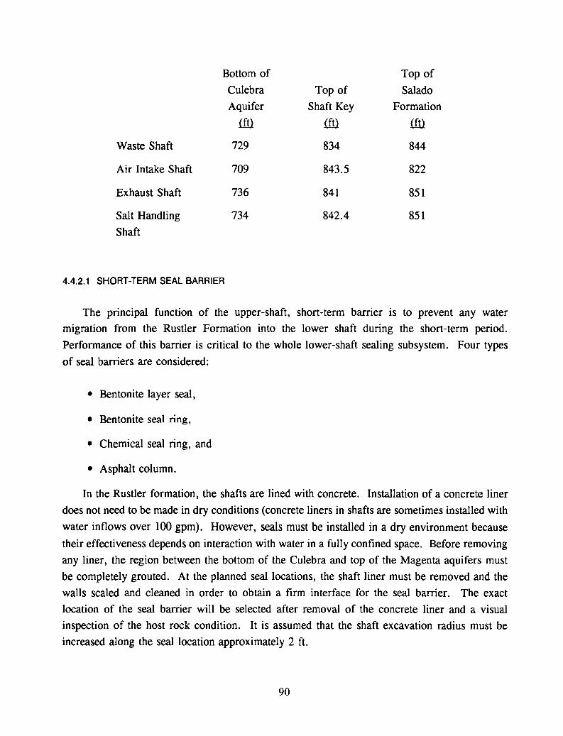
Bottom of Top of
Culebra Top of Salado
Aquifer Shaft Key Formation
!ill !ill !ill
Waste Shaft 729 834 844
Air Intake Shaft 709 843.5 822
Exhaust Shaft 736 841 851
Salt Handling 734 842.4 851Shaft
4.4.2.1 SHORT-TERM SEAL BARRIER
The principal function of the upper-shaft, short-term barrier is to prevent any water
migration from the Rustler Formation into the lower shaft during the short-term period.
Performance of this barrier is critical to the whole lower-shaft sealing subsystem. Four types
of seal barriers are considered:
• Bentonite layer seal,
• Bentonite seal ring,
• Chemical seal ring, and
• Asphalt column.
In the Rustler formation, the shafts are lined with concrete. Installation of a concrete liner
does not need to be made in dry conditions (concrete liners in shafts are sometimes installed with
water inflows over 100 gpm). However, seals must be installed in a dry environment because
their effectiveness depends on interaction with water in a fully confined space. Before removing
any liner, the region between the bottom of the Culebra and top of the Magenta aquifers must
be completely grouted. At the planned seal locations, the shaft liner must be removed and the
walls scaled and cleaned in order to obtain a firm interface for the seal barrier. The exact
location of the seal barrier will be selected after removal of the concrete liner and a visual
inspection of the host rock condition. It is assumed that the shaft excavation radius must be
increased along the seal location approximately 2 ft.
90
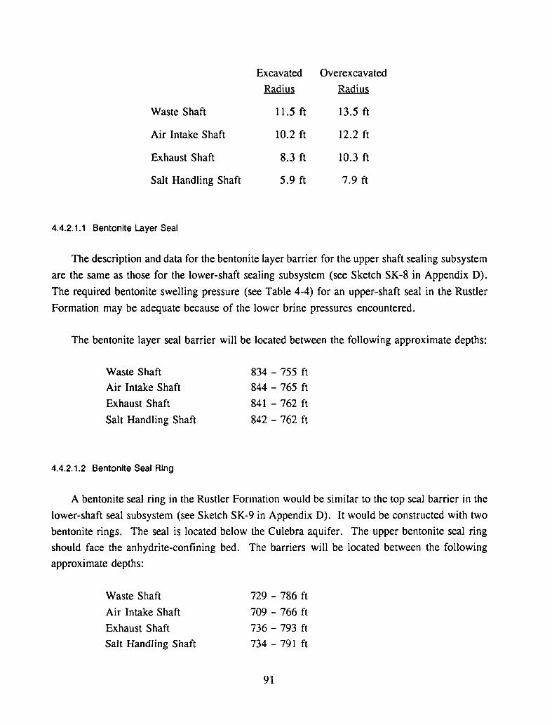
Excavated Overexcavated
Radius Radius
Waste Shaft 11.5 ft 13.5 ft
Air Intake Shaft 10.2 ft 12.2 ft
Exhaust Shaft 8.3 ft 10.3 ft
Salt Handling Shaft 5.9 ft 7.9 ft
4.4.2.1.1 Bentonite Layer Seal
The description and data for the bentonite layer barrier for the upper shaft sealing subsystem
are the same as those for the lower-shaft sealing subsystem (see Sketch SK-8 in Appendix D).
The required bentonite swelling pressure (see Table 4-4) for an upper-shaft seal in the Rustler
Formation may be adequate because of the lower brine pressures encountered.
The bentonite layer seal barrier will be located between the following approximate depths:
Waste Shaft
Air Intake Shaft
Exhaust Shaft
Salt Handling Shaft
4.4.2.1.2 Bentonite Seal Ring
834 - 755 ft
844 - 765 ft
841 - 762 ft
842 - 762 ft
A bentonite seal ring in the Rustler Formation would be similar to the top seal barrier in the
lower-shaft seal subsystem (see Sketch SK-9 in Appendix D). It would be constructed with two
bentonite rings. The seal is located below the Culebra aquifer. The upper bentonite seal ring
should face the anhydrite-confining bed. The barriers will be located between the following
approximate depths:
Waste Shaft
Air Intake Shaft
Exhaust Shaft
Salt Handling Shaft
729 - 786 ft
709 - 766 ft
736 - 793 ft
734 - 791 ft
91
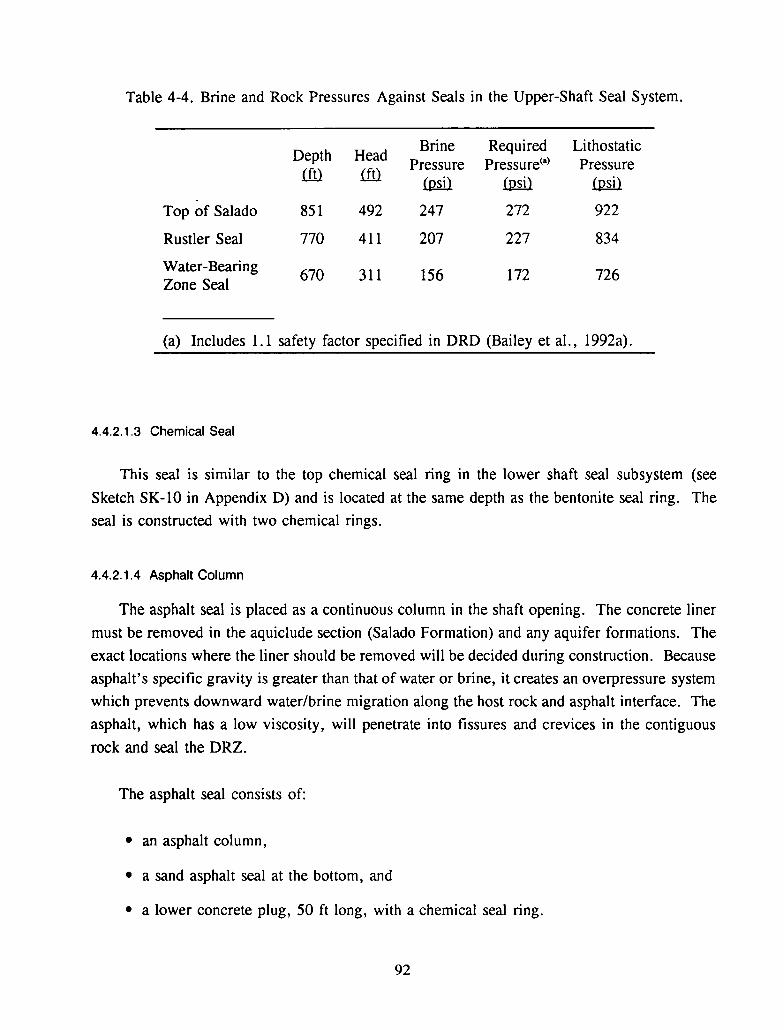
Table 4-4. Brine and Rock Pressures Against Seals in the Upper-Shaft Seal System.
Depth HeadBrine Required Lithostatic
Pressure Pressure(a) Pressureill.) ill.)
Will Will WillTop of Salado 851 492 247 272 922
Rustler Seal 770 411 207 227 834
Water-Bearing670 311 156 172 726
Zone Seal
(a) Includes 1.1 safety factor specified in DRD (Bailey et at, 1992a).
4.4.2.1.3 Chemical Seal
This seal is similar to the top chemical seal ring in the lower shaft seal subsystem (see
Sketch SK-lO in Appendix D) and is located at the same depth as the bentonite seal ring. The
seal is constructed with two chemical rings.
4.4.2.1.4 Asphalt Column
The asphalt seal is placed as a continuous column in the shaft opening. The concrete liner
must be removed in the aquiclude section (Salado Formation) and any aquifer formations. The
exact locations where the liner should be removed will be decided during construction. Because
asphalt's specific gravity is greater than that of water or brine, it creates an overpressure system
which prevents downward water/brine migration along the host rock and asphalt interface. The
asphalt, which has a low viscosity, will penetrate into fissures and crevices in the contiguous
rock and seal the DRZ.
The asphalt seal consists of:
• an asphalt column,
• a sand asphalt seal at the bottom, and
• a lower concrete plug, 50 ft long, with a chemical seal ring.
92
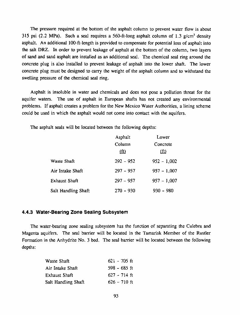
The pressure required at the bottom of the asphalt column to prevent water flow is about
315 psi (2.2 MPa). Such a seal requires a 560-ft-long asphalt column of 1.3 g/cm3 density
asphalt. An additional l00-ft-length is provided to compensate for potential loss of asphalt into
the salt DRZ. In order to prevent leakage of asphalt at the bottom of the column, two layers
of sand and sand asphalt are installed as an additional seal. The chemical seal ring around the
concrete plug is also installed to prevent leakage of asphalt into the lower shaft. The lower
concrete plug must be designed to carry the weight of the asphalt column and to withstand the
swelling pressure of the chemical seal ring.
Asphalt is insoluble in water and chemicals and does not pose a pollution threat for the
aquifer waters. The use of asphalt in European shafts has not created any environmental
problems. If asphalt creates a problem for the New Mexico Water Authorities, a lining scheme
could be used in which the asphalt would not come into contact with the aquifers.
The asphalt seals will be located between the following depths:
Asphalt Lower
Column Concrete
(ffi (ffi
Waste Shaft 292 - 952 952 - 1,002
Air Intake Shaft 297 - 957 957 - 1,007
Exhaust Shaft 297 - 957 957 - 1,007
Salt Handling Shaft 270 - 930 930 - 980
4.4.3 Water-Bearing Zone Sealing Subsystem
The water-bearing zone sealing subsystem has the function of separating the Culebra and
Magenta aquifers. The seal barrier will be located in the Tamarisk Member of the Rustler
Formation in the Anhydrite No.3 bed. The seal barrier will be located between the following
depths:
Waste Shaft
Air Intake Shaft
Exhaust Shaft
Salt Handling Shaft
621 - 705 ft
598 - 685 ft
627 - 714 ft
626 - 710 ft
93

The exact location of the seal will be established after visual inspection of the host rock during
construction.
As the seal has to be installed in a dry environment, both aquifers (Magenta and Culebra)
should be sealed by grouting before removing the existing shaft liner. To obtain an undisturbed
interface between the seal material and rock wall, part of the excavation wall must be removed.
It is assumed that the shaft excavation radius will be increased 1.5 ft at the seal barrier location.
Four alternatives for the seals are considered: a bentonite layer seal, a bentonite seal ring, a
chemical seal ring, and asphalt seal column. The installation of any of these alternatives would
be similar to that described in the lower-shaft sealing subsystem.
4.4.4 Near-Surface Shaft Sealing SUbsystem
The near-surface shaft seal prevents migration of surface water through the interface
between the shaft liner and the Santa Rosa and Gatuna Sandstone Formations. Moreover, it
should form a protective cover for the shaft. This protective cover should be built in the
existing collar structure.
The depths of the existing collars and the Santa Rosa and Gatuna Sandstone Formations are:
Waste Shaft
Air Intake Shaft
Exhaust Shaft
Salt Handling Shaft
21 ft
16 ft
10ft
Santa Rosa and
Gatuna Sandstone
54 ft
45 ft
Preventing water migration on the interface can be achieved through cementitious grouting
of the interface along the Santa Rosa and Gatuna Sandstone Formations. The protective cover
of the shaft will be in the form of a concrete cap located at the surface and built into the existing
collar structure. Below the concrete cap, the inside of the shaft will be filled with earthen fill.
94
4.5 Evaluation of Alternatives
Eight alternative sealing arrangements were considered for the WIPP shafts:
1. Bentonite layer seal and crushed salt (Sketch SK-8 in Appendix D),
2. Bentonite layer seal and quarried-salt blocks (Sketch SK-8 in Appendix D),
3. Bentonite ring seals and crushed salt (Sketch SK-9 in Appendix D),
4. Bentonite ring seals and quarried-salt blocks (Sketch SK-9 in Appendix D),
5. Chemical seal rings and crushed salt (Sketch SK-IO in Appendix D),
6. Chemical seal rings and quarried-salt blocks (Sketch SK-IO in Appendix D),
7. Asphalt seal column and crushed salt (Sketch SK-ll in Appendix D), and
8. Asphalt seal column and quarried-salt blocks (Sketch SK-ll in Appendix D).
The costs for the alternative sealing arrangements and the expected performance of the sealing
materials is described below.
4.5.1 Cost Evaluation
Order-of-magnitude capital costs for the four shafts using the eight shaft sealing alternatives
are shown below. Further breakdowns of the costs are given in Appendix B.
1. Bentonite layer seal and crushed salt . . . . . . . . . . . . . . . . . .. $42,602,000
2. Bentonite layer seal and quarried-salt blocks $69,811,000
3. Bentonite seal ring and crushed salt $33,762,000
4. Bentonite seal ring and quarried-salt blocks . . . . . . . . . . . . . .. $60,950,000
5. Chemical seal ring and crushed salt $39,132,000
6. Chemical seal ring and quarried-salt blocks . . . . . . . . . . . . . .. $66,320,000
7. Asphalt column and crushed salt $46,221,000
8. Asphalt column and quarried-salt blocks " $73,394,000
95

NOTE: The costs shown are for labor and materials only.
4.5.2 Material Performance Evaluation
Each of the eight arrangements of seal components for lower- and upper-shaft sealing
subsystems for the WIPP shafts is expected to comply with the preliminary DRD requirements.
Specific concerns about selecting the appropriate seal materials are addressed for the short-term
and long-term seals in the following subsections.
4.5.2.1 LONG-TERM SEALS
Selection of the long-term seal material ultimately depends on the required length of
reconsolidated salt above the shaft station. Three materials are considered, each with a higher
emplaced fractional density. Emplacement at a higher density results in shorter reconsolidation
times and a longer length of reconsolidated salt. The effective length of the reconsolidated
crushed-salt barrier density after 100 years is expected to be about 310 ft for an emplaced
fractional density of 85 percent. Quarried-salt blocks can be installed at nearly the same density
as intact salt, such that only the salt mortar between blocks requires reconsolidation. The length
of the reconsolidated quarried-salt barrier after 100 years is about 610 ft for an emplaced mortar
volume of 10 percent. Compressed-salt blocks are similar to quarried blocks, but with a lower
block density. The reconsolidated length after 100 years is about 410 ft for blocks with a
starting fractional density of 90 percent and a 10 percent salt-mortar volume.
If a 300-ft-Iength for the long-term salt seal is adequate, then crushed salt emplaced at 85
percent fractional density is the most economical long-term seal material. If the long-term seal
barrier must be more than 300 ft, then either quarried-salt blocks (600 ft reconsolidated length)
or compressed-salt blocks (400 ft reconsolidated length) must be considered, and a higher cost
incurred.
4.5.2.2 SHORT-TERM SEALS
Performance of the short-term barriers is crucial during the first 100 years as the barriers
cannot be monitored, modified, tested, or maintained after installation. Three materials (other
than concrete) were considered for the short-term seals: bentonite, the Dow Chemical seal, and
96
asphalt. The sealing performance of the last two materials has been confirmed through
successful applications in mine shafts. Bentonite performance has not been confirmed in mining
or similar projects.
The complexity of the confined bentonite layer seal component results in high material and
construction costs. Bentonite- and chemical-seal rings, which use a simpler and more
economical structure, provide an attractive sealing arrangement because the reduced volume of
sealing material and simpler construction. Both types of ring seals, however, block the flow
only at the interface with the shaft wall. Flow at locations other than the interface is blocked
by the concrete structures only. An advantage of the Dow Chemical seal ring over the bentonite
seal ring is that it has been successfully applied in mine shafts and has withstood water/brine
pressures up to 1,300 psi. The performance of asphalt as a sealing component has also been
proven in mine shafts. There are no known cases of failure of asphalt as a seal component in
shafts. Based on this experience, it is unlikely that the asphalt seal, if properly installed, will
fail or deteriorate. Asphalt will penetrate into the fissures and openings of the contiguous rock
and decrease the permeability of the DRZ during the short-term sealing period. Installation of
an asphalt seal column, however, is costly and time-consuming.
4.6 Conclusion and Recommendations
The proposed shaft seal alternatives are based on reference design/materials, new material
concepts, and sealing materials used in mine shafts. Sealing nuclear repository shafts is a new
and without-precedent operation. Available information on seal materials developed in
laboratories and scientific institutions is not adequate for engineering design. No engineering
description of a shaft sealing operation of the required performance is available in the literature.
In this alternatives study, additional sealing alternatives are introduced using different, promising
sealing materials. Alternatives were considered for long- and short-term seal barriers. At this
time, a fully defensible recommendation of any of the presented alternatives cannot be made.
The long-term seal alternatives are crushed salt, compressed-salt blocks, and quarried-salt
blocks. Sealing performance for all three alternatives is based on the same premises. The
sealing materials must achieve 95 percent density of the intact salt within 100 years after
emplacement. The length of the seal barrier attaining this density depends on the emplaced
density of each of the three materials.
97
The design criteria (DRD) do not define the required length of the long-term seal barriers.
The crushed salt with an emplaced density of 85 percent could form a 300-ft-Iong seal barrier
in 100 years. During small-scale compaction tests on crushed salt, greater than 85 percent
densities have not been achieved. Four considerations related to the length requirement of the
long-term seal barrier are:
• Decrease length requirement (less than 300 ft) for crushed salt,
• Develop a compacting method for emplacing crushed salt in shaft at greater than 85
percent density,
• Develop a method to fabricate compressed-salt blocks to greater than 90 percent density,
and
• Use quarried blocks.
For the short-term seal barrier, the following alternatives were considered:
• Bentonite layer with two confining plugs,
• Bentonite seal ring or rings around a concrete plug,
• Chemical seal ring or rings around a concrete plug, and
• Asphalt column in the shaft opening.
The first three alternatives are for the lower and upper sealing subsystem, the fourth one is only
for the upper sealing subsystem.
Use of bentonite as a sealing material is promising in the upper sealing subsystem. In order
to use bentonite in the lower sealing subsystem, compaction and swelling pressure tests on an
industrial scale need to be performed. The difference between a bentonite layer seal and a
bentonite ring seal will be mainly in cost. The bentonite layer seal is a full, cross-section seal,
while the bentonite ring seal is an interface (circumferential) seal only.
Chemical seal rings have been used in mine shafts with good results. Since chemical seal
rings can develop high swelling pressure, they can be used in both the lower and upper sealing
subsystems. Studies on the longevity of the chemical seal material and its interaction with brine
water are recommended.
98
Asphalt has been used successfully for sealing shaft linings. There are no known cases of
failure of asphalt as a seal component. It can be expected that asphalt will be a reliable seal in
the upper sealing subsystem including the water-bearing zone. In addition, the penetration of
asphalt into the contiguous rock will help seal the fractures in the DRZ.
99

100
5.0 BOREHOLE SEALS
The borehole seals portion of the alternatives study was performed by first identifying
and describing the purpose and requirements for the borehole seals. The purpose and
requirements described in Sections 5.1 and 5.2 were taken from the DRD (Bailey et al.,
1992a).
Secondly, the boreholes requiring sealing (Section 5.3) and sealing strategies (Section
5.4) were identified. Two schemes were evaluated: (1) the DRD borehole sealing scheme,
which involves only boreholes located within the facility boundary, and (2) a proposed
alternative scheme, which is based on Christensen et al. (1983) borehole classification.
Thirdly, four sealing alternatives, comprising cementitious grout, asphalt and
combinations of cementitious grout, crushed salt, and crushed salt/bentonite mix were
evaluated. Materials, emplacement methods, and constructibility considerations are
discussed in Section 5.6.
Finally, the alternatives are evaluated in terms of their effectiveness and costs in Section5.7, and discussions and conclusions are given in Section 5.8.
5.1 Purpose
Boreholes drilled in the vicinity of the repository are potential preferential pathways for
groundwater flow and hazardous mixed waste release to the accessible environment. To
mitigate this potential, borehole seals will be designed to limit the volume of water that
could be introduced via the boreholes to the reposito....j from the overlying water-bearingzones and the amount of contaminated brine that could move up the boreholes to either the
surface or the water-bearing zones.
This portion of the seal design alternative study examines and compares four borehole
sealing alternatives with respect to seal effectiveness, emplacement techniques, and order-of
magnitude capital cost for three cases as follows:
Case 1 - Nine boreholes located within the facility boundary as indicated in the DesignRequirements Document (DRD);
101
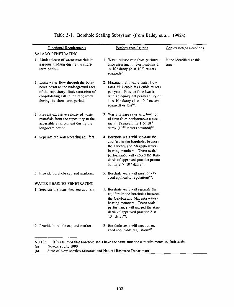
Table 5-1. Borehole Sealing Subsystem (from Bailey et aI., 1992a)
Functional Requirements
SALADO PENETRATING
1. Limit release of waste materials ingaseous medium during the shortterm period.
2. Limit water flow through the boreholes down to the underground areaof the repository; limit saturation ofconsolidating salt in the repositoryduring the short-term period.
3. Prevent excessive release of wastematerials from the repository to theaccessible environment during thelong-term period.
4. Separate the water-bearing aquifers.
5. Provide borehole cap and markers.
WATER-BEARING PENETRATING
1. Separate the water-bearing aquifers.
2. Provide borehole cap and marker.
Performance Criteria
1. Waste release rate from performance assessment. Permeability 2x 10⁻⁷ darcy (2 X 10-19 meterssquared)(a) .
2. Maximum allowable water flowrates 35.3 cubic ft (1 cubic meter)per year. Provide flow barrierwith an equivalent permeability of1 x 10-7 darcy (l x 10-19 meterssquared) or less(a).
3. Waste release rates as a functionof time from performance assessment. Permeability 1 x 10⁻⁸
darcy (10-20 meters squared)(').
4. Borehole seals will separate theaquifers in the boreholes betweenthe Culebra and Magenta waterbearing members. These seals'performance will exceed the standards of approved practice permeability 2 x 10⁻⁷ darcy(').
5. Borehole seals will meet or exceed applicable regulations(h).
1. Borehole seals will separate theaquifers in the boreholes betweenthe Culebra and Magenta waterbearing members. These seals'performance will exceed the standards of approved practice 2 x10⁻⁷ darcy(a).
2. Borehole seals will meet or exceed applicable regulations(h).
Constraints/Assumptions
None identified at thistime.
NOTE: It is assumed that borehole seals have the same functional requirements as shaft seals.(a) Nowak et aI.. 1990(b) State of New Mexico Minerals and Natural Resource Department
102

Case 2 - Twelve boreholes meeting Condition 1 (see Section 5.3); and
Case 3 - Fifteen boreholes meeting Conditions 1 and 2 (see Section 5.3).
5.2 Requirements for the Borehole Seals
Preliminary functional requirements and performance criteria for Salado penetrating and
water-bearing penetrating borehole seals are provided in the DRD (Bailey et aI., 1992a) and
reproduced here in Table 5-1. According to the DRD, the water-bearing penetrating
borehole seals (WBBS) separate the water-bearing aquifers and a borehole cap and marker
are to be provided. The DRD gives the Salado-penetrating borehole seals (SBS) the
following short-term and long-term functional requirements.
For the short term, the Salado-penetrating borehole seals shall:
• limit release of waste material in gaseous form,
• limit water flow through the boreholes down to the underground area of the
repository, and
• limit saturation of consolidating salt in the repository.
During the long-term period, the Salado-penetrating borehole seals shall prevent excessive
release of waste material from the repository to the accessible environment.
An assumption explicitly made in the DRD is that borehole seals have the same
functional requirements as shaft seals. Further definition of borehole criteria is planned by
Sandia National Laboratories and it is anticipated that modifications will be made because
of different functions and locations of boreholes. Note-worthy differences between shafts
and boreholes that have implications on sealing include:
• Location - Unlike the boreholes, the shafts are a direct link between the repository
and the upper aquifers,
• Size - According to Daemen et ai. (1983), there would be a much greater
generation of heat of hydration for cement-based plugs in shafts than in boreholes,
103

• WIPP-19
StorageBorehole Depth (tt) Area
ERDA-9 2877WIPP-19 1038WIPP-21 1046WIPP-22 1448
H-1 856H-2 795H-3 894
N
j
•H-2 Hydropad
Experimental [ ===~DDDDDI ID~~DArea 0 •WIPP-22
oLJa~ ·WIPP-21
~~~000 • ERDA-9
DOD~_ 000L...-----,---,----,DD~DDDDDDDDDDDDDD
H-1 DDDL--_~
DDDDDDDDDDDDDDDDD~_DDDL...------.
DDDDDDDDDDDDDDDDD...---_DDDl.---_DDDDDDDDDDDDDDDDD
(trom Beauheim, 1987)
Reference Depth of Repository: 2150 It •H-3 Hydropad
TRI·6330·34·3
Figure 5-1. Approximate locations of boreholes in relation to the WIPP underground (fromLappin et aI., 1989, p. 1-3).
104

• Emplacement method - As opposed to shaft sealing, borehole sealing entailsremote emplacement,
• Excavation method - Blasting during excavation for some of the shafts would cause
fracturing of surrounding rock and increase the DRZ. Field and laboratory tests
indicate only a small effect of the disturbed zone is associated with boreholes (less
than 3 percent of the borehole radius vs. 30 to 100+ percent of the radius for shafts;Christensen and Peterson, 1981; Kelsall et aI., [1982]), and
• Seal Construction Schedule - Whereas shafts must be left open during theoperational phase, boreholes can be sealed now or later.
5.3 Boreholes Requiring Sealing
Existing borehole and casing locations and depths are presented in Appendix B of
Brinster (1991) as a compilation of geohydrologic data from various sources. Coordinates
given for each borehole in Table B-1 of Brinster are Universal Transverse Coordinates
converted to the study area coordinates.
Figure 4-11 of the Data Base Document shows boreholes within the facility boundary
as those to be sealed. This figure is reproduced here as Figure 5-1.
Sketch SK-12 in Appendix D of this report presents three location figures - the WIPP
Site Boring Locations (Stormont, 1984), a General Location Map (adapted from Lappin et
aI., 1989), and a figure showing Borehole Classification as to Location (Christensen et aI.,
1983). The Borehole Classification as to Location is an alternative scheme which could be
used to determine boreholes requiring sealing.
Christensen et al. (1983) proposes plugging only those boreholes meeting either
Condition 1 or Condition 2, defined as follows.
Condition 1: Boreholes terminating in the Salado formation and within 300 m (1,000
ft) horizontally of the maximum potential lateral extent of repository development.
(This involves 12 boreholes.)
105
Condition 2: Boreholes terminating below the Salado/Castile interface within 3,168
m (2 miles) of the site center. These boreholes might link the upper and lower
aquifers and could conceivably exhibit a two-aquifer communication scenario with
faster diffusion rates than those in Condition 1. (This involves 3 additional
boreholes.)
Boreholes meeting either of these conditions are identified in Christensen et al. (1983) and
in Sketch SK-12 in Appendix D, and may be sealed in accordance with the functional
requirements and performance criteria defined in the DRD. Technically, however, the seals
for these boreholes do not need to meet the stringent requirements of the DRD.
5.4 Borehole Sealing Strategy
The conclusions reached from consideration of a worst-case, two-aquifer communication
scenario in open existing boreholes, as part of the Final Environmental Impact Statement
(FEIS, US DOE, 1980) and from a study by Intera Environmental Consultants, Inc. (1981)
are incorporated into the sealing strategy. In this scenario, an uncased, open borehole is
assumed to penetrate the Rustler, the center of the repository, and the Bell Canyon aquifer.
Such a borehole, which connects the upper and lower aquifers, might dissolve salt faster
than one penetrating only the upper aquifer because circulation could be established
between the two aquifers in the former case. Based on flow rates calculated from the FEIS
assessments for the two-aquifer communication scenario, it would take more than 1.3 My
(for the unplugged case) and 30 My (for the plugged case) to dissolve the repository
contents. The plugged case assumes that the cement grout used ultimately degrades to a
condition equivalent to that of sand. The whole-body dose received by the maximallyexposed individual is about 0.012 percent of the natural background radiation. Subsequent
hydrologic investigations and calculations by Intera (1981) indicate that the FEIS
calculations are very conservative.
None of the existing boreholes penetrate the WIPP facility. Therefore, salt has to be
dissolved between a borehole and the repository for breach of the repository to occur. In
boreholes penetrating only the upper aquifer, the dissolution is controlled by diffusion and
proceeds so slowly that it poses no threat to the WIPP even if the borehole were left open
(Stormont, 1988).
106
Since concerns regarding long-term performance are alleviated for borehole seals,
cementitious mixtures can be used as the principal seal material (Stormont, 1988).
Borehole sealing entails remote emplacement and requires the sealing materialcompletely fill the borehole and makes good contact with the borehole wall, especially in
boreholes penetrating rock susceptible to substantial washouts (Christensen et aI., 1980).
Cement grouts have known flow properties and established emplacement techniques that
produce good rock/seal contact. Even if the grout degrades into its constituents (principallysand), adequate resistance to flow should exist (Stormont, 1984).
5.5 Evaluation Considerations
To fulfill their primary functions as detailed in Section 5.2, borehole plugs should
provide a variety of secondary functions, including mechanical support for the surroundingrock, maintenance of their own physical integrity, and minimization of water movement.
5.5.1 Seal Effectiveness
The effectiveness of the seal material is examined from the following perspectives.
• Permeability of the seal - the performance criterion for borehole seals with regardsto permeability is given in the DRD as 1 x 10⁻⁷ darey (1 x 10-19 m2
) or less, ascompared to the expected permeability of the host rock salt 10-10 to 10-8 darey (10-22
to 10-20 m2).
• Stability/Longevity - prediction of long-term behavior of seal materials using
models is difficult to verify because of the diversity between the seal and rockmaterial and the long time of interest. Similarity between the seal material and itshost formation implies compatibility, which increases long-term stability of thesealing system, reduces the burden on predictive modeling, and adds confidence in
long-term isolation.
• Swell Potential - the potential of the seal material to swell, fill voids, heal fractures
within the seal and the host rock.
107
• Remediation of Disturbed Rock Zone (DRZ) - the potential for increased
permeability within a DRZ is of concern to any sealing program. Around a
borehole, the DRZ results primarily from energy imparted during drilling. Field
tests indicate only a small disturbed zone is associated with boreholes (Christensen
and Peterson, 1981).
5.5.2 Emplacement Techniques
It is not obvious that all candidate seal materials can be adequately emplaced and retain
the low permeabilities (exhibited in laboratory tests) over an extended period of time. In
particular, remote emplacement poses special problems for some seal material types
including assurance of complete filling of the void and avoiding bridging. The technology
for cementing of boreholes (whether cased or not) is well established and considerable
experience exists within contractor organizations.
5.6 Description of Alternatives
Four candidate borehole sealing alternatives (see Sketch SK-13 in Appendix D), are
considered.
• Alternative A - A cementitious grout alternative, using the reference saltwater
(BCf-lF) and freshwater (BCf-lFF) formulations described by Gulick and Wakeley
(1987).
• Alternative B - An alternative using BCf-lFF grout in combination with crushed
salt.
• Alternative C - An alternative usmg BCT-IFF grout m combination with a
bentonite-crushed-salt mixture.
• Alternative D - An alternative using asphalt.
108
5.6.1 Definition
5.6.1.1 ALTERNATIVE A: CEMENTITIOUS GROUT
Gulick and Wakeley (1987) provide the reference formulations and properties for
candidate grouts to be used in the WIPP sealing program. Both a freshwater grout (BCf
IFF) and a saltwater grout (BCf-lF) are specified. As shown in Sketch SK-13 in Appendix
D, Alternative A would place saltwater grout in the borehole to the top of the Culebra
dolomite member (approximately at 200 m (700 ft)). The use of saltwater grout in the
Salado would preclude dissolution of the host rock. The freshwater grout mix would then
be used to fill up the borehole to the ground surface (approximately the remaining nonsalt
strata). A concrete plug would be placed at the top of the borehole, as shown in Sketch SK
13 in Appendix D.
5.6.1.2 ALTERNATIVE B: FRESHWATER GROUT AND CRUSHED SALT
In Alternative B, crushed salt would replace the saltwater BCf-lF grout in Alternative
A. Crushed salt would be placed generally from the bottom of the borehole to a depth of
approximately 200 m (700 ft). To protect the underlying crushed salt from saturation by
inflow of water from the upper aquifer, a single, 4-m-Iong (13-ft) bentonite seal would be
placed above it. Calculations by Stormont and Arguello (1988) show that this length of
bentonite seal would sufficiently reduce water flow to the crushed-salt layer to allow
reconsolidation of the crushed salt. Freshwater grout mix would then be used to fill up the
borehole to the ground surface. A concrete plug would be placed at the top of the
borehole, as shown in Sketch SK-13 in Appendix D.
5.6.1.3 ALTERNATIVE C: FRESHWATER GROUT AND BENTONITE-CRUSHED SALT
Alternatives Band C are identical except that the crushed salt in Alternative B would
be replaced with a bentonite/crushed-salt mixture in Alternative C. Use of bentonite as a
sealing material is discussed in Section 4.3.1.
109
5.6.1.4 ALTERNATIVE 0: ASPHALT
Alternative D would use asphalt exclusively to seal the boreholes. Previous WIPP sealconcepts have not included asphalt, and the experimental program has not evaluated asphalt
as a candidate seal material. As previously noted by Stormont (1988), asphalt warrants
consideration as a possible seal material based on its successful applications, especially in
Germany.
Asphalt's low viscosity enables it to penetrate fissures of the DRZ in the contiguous
rock and to displace water. The degree of penetration depends on the width of fissures,
viscosity of the asphalt, pressure of the asphalt column, and the time for penetration. Useof asphalt as a sealing material is discussed in Section 4.3.5.1.
The asphalt in Alternative D is produced by mixing bitumen with limestone filler at high
temperatures. To reduce the possibility of asphalt running out into the formation
continuously leading to an incessant fall in the level of asphalt, type 80 or type 65 asphalt
should be considered. The penetration rate of the candidate asphalt decreases with
increasing penetration depth. The time at which asphalt flow into the borehole walls ceases
depends basically on the width of the fissures (Kerkhoven, 1959). The depth of asphalt
penetration will diminish when dust filler particles are included. The asphalt and limestone
filler mixture should be homogeneous, free from water, and should not foam when heated
to 370°F. Furthermore, it should conform to requirements of the American Association ofState Highway and Transportation Officials (AASHTO) and the American Society forTesting and Materials (ASTM) publications for Asphalt and Filler Materials. A concrete
plug would be placed at the surface, as shown in Sketch SK-13 in Appendix D.
5.6.2 Emplacement Considerations and Constructibility
5.6.2.1 BOREHOLE CLEANING AND CONDITIONING
Boreholes would be surveyed by downhole TV camera methods, and/or geophysical and
caliper logs taken to determine the extent of borehole deterioration, including borehole
enlargement or closure, or any other conditions which could adversely affect the emplace
ment/performance of seals. Boreholes would be cleaned and conditioned, as required, priorto sealing. This may involve washing, reaming and, if necessary, redrilling the boreholes to
provide fresh and stable borehole walls. These measures would ensure the integrity of theboreholes as it affects seal placement and performance.
110
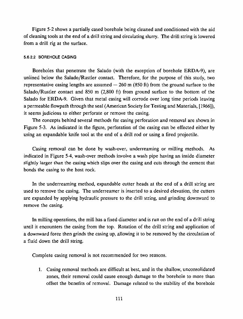
Figure 5-2 shows a partially cased borehole being cleaned and conditioned with the aid
of cleaning tools at the end of a drill string and circulating slurry. The drill string is lowered
from a drill rig at the surface.
5.6.2.2 BOREHOLE CASING
Boreholes that penetrate the Salado (with the exception of borehole ERDA-9), are
unlined below the Salado/Rustler contact. Therefore, for the purpose of this study, two
representative casing lengths are assumed - 260 m (850 ft) from the ground surface to the
Salado/Rustler contact and 850 m (2,800 ft) from ground surface to the bottom of the
Salado for ERDA-9. Given that metal casing will corrode over long time periods leaving
a permeable flowpath through the seal (American Society for Testing and Materials, [1966]),
it seems judicious to either perforate or remove the casing.
The concepts behind several methods for casing perforation and removal are shown in
Figure 5-3. As indicated in the figure, perforation of the casing can be effected either by
using an expandable knife tool at the end of a drill rod or using a fired projectile.
Casing removal can be done by wash-over, underreaming or milling methods. As
indicated in Figure 5-4, wash-over methods involve a wash pipe having an inside diameter
slightly larger than the casing which slips over the casing and cuts through the cement that
bonds the casing to the host rock.
In the underreaming method, expandable cutter heads at the end of a drill string are
used to remove the casing. The underreamer is inserted to a desired elevation, the cutters
are expanded by applying hydraulic pressure to the drill string, and grinding downward to
remove the casing.
In milling operations, the mill has a fixed diameter and is run on the end of a drill string
until it encounters the casing from the top. Rotation of the drill string and application of
a downward force then grinds the casing up, allowing it to be removed by the circulation of
a fluid down the drill string.
Complete casing removal is not recommended for two reasons.
1. Casing removal methods are difficult at best, and in the shallow, unconsolidated
zones, their removal could cause enough damage to the borehole to more than
offset the benefits of removal. Damage related to the stability of the borehole
111
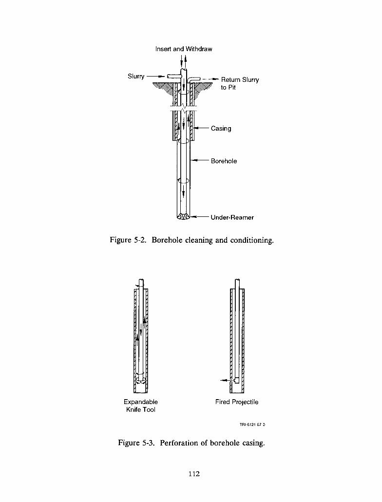
Insert and Withdraw
t-- Borehole
Under-Reamer
Figure 5-2. Borehole cleaning and conditioning.
ExpandableKnife Tool
Fired Projectile
TRI-6121-67-0
Figure 5-3. Perforation of borehole casing.
112
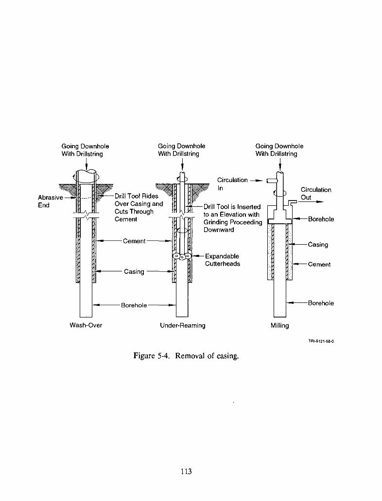
Going DownholeWith Drillstring
t
..CirculationOut
I Casing
.:--Cement
t----Borehole
L......,r---Boreholehr--cr't
Circulation In
ExpandableCutterheads
7
jt Drill Tool is Insertedto an Elevation withGrinding ProceedingDownward
Going DownholeWith Drillstring,
_. '\
o 0 0 '--
-
Drill Tool RidesOver Casing andCuts ThroughCement
.. Casing
l-tl----Cement
1-->-----Borehole
-
Going DownholeWith Drillstring
t
Wash-Over Under-Reaming Milling
TRI-6121-SS-0
Figure 5-4. Removal of casing.
113

walls and subsequent borehole enlargement would be likely in the shallower
zones; therefore, it is not recommended that milling operations be attempted as
this would require all the casing be removed. However, at greater depths where
the formations are more consolidated and certainly in the salt sections, theunderreaming method of casing removal would be possible. As a precautionary
note, it should be understood that as the depth increases, the difficulty of the
mechanical work increases, but the maximum depth of 2,800 ft is certainly within
the current technology level for the underreaming of casing.
2. Removal of the casing in any of the boreholes where fresh water is cemented
behind the casing could facilitate fresh water inflow from the upper aquifer,
making sealing of the lower portions of the boreholes difficult for Alternatives
Band C, which use crushed salt.
Well casings can be perforated as an alternative to casing removal. Each well should
be carefully evaluated to determine if perforating or selective casing removal would be the
best solution. If perforating is chosen, a fired projectile is the recommended method of
perforating. The perforation interval and the thickness of the injection zone would depend
on the sealing alternative.
It is proposed that casings be perforated with a fired projectile in all cases, except for
alternatives using the crushed salt or bentonite/crushed-salt mix, where casing removalbelow the Salado/Rustler contact would be warranted. The perforation interval andthickness of the injection zone would depend on the sealing alternative.
5.6.2.3 CEMENTITIOUS GROUT INJECTION
Figure 5-5 illustrates an emplacement concept for placing cementitious grout mix in the
borehole. The grout pipe is filled with the grout mix and lowered to the bottom of the
cleaned borehole. The mix is then deposited by opening the foot valve located at the
bottom of the grout pipe. The pipe is withdrawn as the mix is being deposited. The tip of
the pipe is maintained at a minimum of three borehole diameters below the surface of thegrout mix to ensure absence of entrapped air in the deposited mix.
114
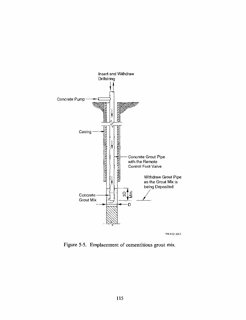
Insert and WithdrawDrillstring
H
Casing -
f-o-7-"-- Concrete Grout Pipewith the RemoteControl Foot Valve
Withdraw Grout Pipeas the Grout Mix isbeing Deposited
~_~....L---I
TRI-6121-69-Q
Figure 5-5. Emplacement of cementitious grout mix.
115
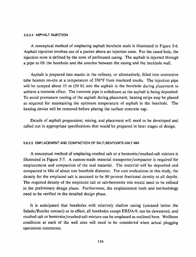
5.6.2.4 ASPHALT INJECTION
A conceptual method of emplacing asphalt borehole seals is illustrated in Figure 5-6.Asphalt injection involves use of a packer above an injection zone. For the cased hole, theinjection zone is defined by the zone of perforated casing. The asphalt is injected througha pipe to fill the borehole and the annulus between the casing and the borehole wall.
Asphalt is prepared into mastic in the refinery, or alternatively, filled into convectivetube heaters on-site at a temperature of 350°F from insulated trucks. The injection pipewill be sumped about 15 m (50 ft) into the asphalt in the borehole during placement toachieve a tremmie effect. The tremmie pipe is withdrawn as the asphalt is being deposited.To avoid premature cooling of the asphalt during placement, heating strips may be placedas required for maintaining the optimum temperature of asphalt in the borehole. Theheating device will be removed before placing the surface concrete cap.
Details of asphalt preparation, mixing, and placement will need to be developed andcalled out in appropriate specifications that would be prepared in later stages of design.
5.6.2.5 EMPLACEMENT AND COMPACTION OF SALT/BENTONITE-SALT MIX
A conceptual method of emplacing crushed salt or a bentonite/crushed-salt mixture is
illustrated in Figure 5-7. A custom-made material transporter/compactor is required foremplacement and compaction of the seal material. The material will be deposited andcompacted in lifts of about one borehole diameter. For cost evaluations in this study, thedensity for the emplaced salt is assumed to be 80 percent fractional density at all depths.
The required density of the emplaced salt or salt-bentonite mix would need to be refinedin the preliminary design phase. Furthermore, the emplacement tools and methodologyneed to be verified in the detailed design phase.
It is anticipated that boreholes with relatively shallow casing (uncased below theSalado/Rustler contact) or in effect, all boreholes except ERDA-9, can be dewatered, andcrushed salt or bentonite/crushed-salt mixture can be emplaced as outlined here. Wellbore
conditions at each of the well sites will need to be considered when actual pluggingoperations commence.
116
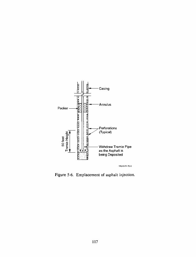
1lUl:-caSing
Packer --oi~
1:Cl--w
alI- Q)0--Il) E
~I-
.. Annulus
117Pertorations~V (Typical)
~:---;;.----- Withdraw Tremie Pipe
as the Asphalt isbeing Deposited
TRI-6121-70-0
Figure 5-6. Emplacement of asphalt injection.
117
Insert and WithdrawWireline Bailer
Raise and DropTamper
Casing ,
;;.-----Casing
Perforated or UnderReamed Interval
~---Wire Tamper
Wireline -----+-".~
Bailer ~
~
Crushed Salt/--~Bentonite Material
Step #1 Step #2
TRI·6121·71·Q
Figure 5-7. Emplacement and compaction of crushed-salt/bentonite salt mix.
118

5.7 Evaluation of Alternatives
This section will compare and evaluate the relative strengths and weaknesses of the
candidate borehole seal alternatives using the evaluation criteria identified in Section 5.5.
No attempt to either rank them or pick the best seal alternative will be made in this seal
design alternative study.
5.7.1 Seal Effectiveness
Permeability - According to the DRD, the short-term performance criterion for
limiting waterflow for boreholes is given as 1 x 10⁻⁷ darcy (1 x 10-19 m2).
Both BCf 1-FF (fresh water grout) and bentonite seals have permeabilities of 1 x 10⁻⁷
darcy (1 x 10-19 m2), which meet the short-term performance requirements. By using the
coarser available grinds of cement and using water reducers and retarders, the water-to
cement ratio in the grouts was reduced, thus reducing permeability and porosity andincreasing density and strength.
In summary, with regards to permeability, Alternative A (the cementltlOus grout
alternative) would readily satisfy the short-term performance criteria in the DRD, required
to:
• limit release of waste materials in gaseous form during the short-term period, and
• limit water flow through the boreholes, down to the underground area of the
repository, etc.
However, the sealing alternative barely satisfies performance criterion during the long-term
period. It is recognized that the physical separation of the boreholes from the repository
will likely preclude any waste material from ever entering the boreholes.
On the other hand, Alternatives Band C which would use crushed salt or bentonite
crushed salt mixture might meet both short and long-term criteria for the corresponding
functions outlined. Creep of host rock from the bottom of hole to about a 1,800-ft-depthis expected to adequately reconsolidate the crushed-salt fill (as was discussed in Section 4).
119
Asphalt (proposed in Alternative D) is a bituminous material produced by the
distillation of crude oil. Many of its properties can be tailored by the distillation process
and by the addition of weighting materials and blending and dissolving agents. Thefunctional requirements can therefore be called out in the specifications.
Stability/Longevity - Real-time observance of the long-term chemical and mechanical
stability of sealing materials in their host geologic environment is not possible. Therefore,
similarity between the seal material and the host formation enhances compatibility, which
increases long-term stability of the sealing system.
Asphalt should perform well as a long-term seal because bacterial degradation requires
micro-organisms and moisture and proceeds very slowly even when these conditions are met
(ZoBell and Molecke, 1978). To reduce the possibility of asphalt running out into the
formation and leading to an incessant fall in the level of asphalt, type 80 or type 65 asphalt
should be considered.
With regard to bentonite, clays exist naturally in geologic formations, including bedded
salt, and clay sealants have been used by man for as long as 2,100 years (Lee, 1985).
Furthermore, at nonelevated temperatures, bentonite transformations to other clays are
expected to be very slow, on the order of millions of years (Meyer and Howard, 1983).
The long-term stability of the cementitious grout formulations BCf I-F and BCf I-FF
is unknown. Even though sulfate attack is resisted by developing cements low in tricalcium
aluminate, cementitious grouts will usually not be in chemical equilibrium with their
environment (Lambert, 1980). Potential mineralogic phase changes in the plug, rock, and
groundwater system could occur.
In summary, Alternatives Band C which utilize crushed salt and bentonite, albeit in
conjunction with the freshwater grout formulation, have merit. Similarly, Alternative D,
which uses asphalt, has merit as well. However, long-term stability of Alternative A (with
its cementitious grouts) is uncertain.
Swell Potential - Mixtures containing bentonite develop swelling pressures if confined
and saturated with water. Therefore, the bentonite/crushed-salt mixture in Sealing
Alternative C should swell and fill voids, heal fractures within the bentonite seal and also,
to a limited degree, in the adjacent host rock. Consequently, the crushed-salt filler material
120

merely acts as an inert filler, and the swelling pressures of the mixture should dependprimarily on the effective clay density (Gray et a1., 1984).
Alternative C (bentonite/crushed-salt mixture in combination with BCT I-FF grout) isthe superior alternative in this regard. The Ber-IFF grout is an expansive grout, developed
to improve the interface bonding with the host rock. The expansion is based on the
form,ation of calcium aluminate phases such as ettringite (Gulick et a1., 1982). The
expansion will improve the mechanical bond and should reduce plug movement andpermeability especially at the interface.
Remediation of the DRZ - The DRZ surrounds the borehole in rock and has physicalcharacteristics differing from those of the virgin formation. The potential for increasedpermeability in this zone is of concern to the WIPP sealing program.
Effective cementitious grouts to be used in grouting fractures in the host rock need to
be developed in the preliminary design phase to supplement the data in the DBD. Crushedsalt/bentonite seals will provide backpressure which will eventually heal the DRZ.
Asphalt in Alternative D has a specific gravity that is 30 to 40 percent greater thanwater. It therefore tends to move out into the formation rather than formation watermoving into the borehole. Its low viscosity facilitates its penetration into fissures andfractures of the host rock. It will also provide some backpressure to heal the DRZ.
5.7.2 Emplacement Techniques
The desirability of a crushed-salt seal option is offset by concerns regarding inadequateremote emplacement techniques and poor consolidation when saturated with brine from thehost rock salt. Concerns over bridging during remote emplacement in a relatively smalldiameter can be reduced by initially screening the salt to eliminate large grains. However,the conceptual emplacement method discussed in Section 5.6.2.5 using a material
transporter/ compactor should be considered.
It should be noted that for Alternatives Band C, the casing in boring ERDA-9 would
have to be removed below about 213 m (700 ft), despite the difficulty anticipated with casing
removal. This would be necessary to ensure a continuous interface between the crushed-saltseal and the halite host rock in the zone occupied by the crushed-salt seal.
121
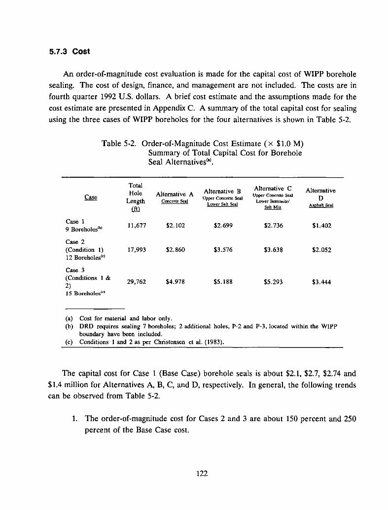
5.7.3 Cost
An order-of-magnitude cost evaluation is made for the capital cost of WIPP boreholesealing. The cost of design, finance, and management are not included. The costs are in
fourth quarter 1992 U.S. dollars. A brief cost estimate and the assumptions made for thecost estimate are presented in Appendix C. A summary of the total capital cost for sealing
using the three cases of WIPP boreholes for the four alternatives is shown in Table 5-2.
Table 5-2. Order-of-Magnitude Cost Estimate (x $1.0 M)Summary of Total Capital Cost for BoreholeSeal Alternatives(al .
Total Alternative CHole Alternative A Alternative B Alternative
Case Upper Concrete Seal
Length Concrete SealUpper Concrete Seal
Lower BentoniteJ DLower Salt Seal Asphalt Seal
® Salt Mix
Case 111,677 $2.102 $2.699 $2.736 $1.4029 Boreholes(b)
Case 2(Condition 1) 17,993 $2.860 $3.576 $3.638 $2.05212 Boreholes<C)
Case 3(Conditions 1 &
29,762 $4.978 $5.188 $5.293 $3.4442)15 Boreholes<cl
(a) Cost for material and labor only.(b) DRD requires sealing 7 boreholes; 2 additional holes, P-2 and P-3, located within the WIPP
boundary have been included.(c) Conditions 1 and 2 as per Christensen et al. (1983).
The capital cost for Case 1 (Base Case) borehole seals is about $2.1, $2.7, $2.74 and$1.4 million for Alternatives A, B, C, and D, respectively. In general, the following trendscan be observed from Table 5-2.
1. The order-of-magnitude cost for Cases 2 and 3 are about 150 percent and 250percent of the Base Case cost.
122

2. There is no significant cost difference among Alternatives A, B, and C and thecost of Alternative D is about one-third less than those of Alternatives A, B, and
C.
3. The worst case cost for WIPP borehole seals considering Conditions 1 and 2borehole seals (15 total) is about 5 million dollars in fourth quarter 1992 costs.
5.8 Discussions and Conclusions
5.8.1 Discussions
Except for Alternative D which uses asphalt exclusively, the alternatives examined in this
study use cementitious grouts, crushed salt, bentonite, and concrete in various combinations.
Alternative A - This alternative uses cementitious grout for the whole length of theborehole. The simplicity of handling and emplacement of the grout makes it an attractivealternative. It meets the short-time performance criteria called out in the DRD; however,
the geochemical and geophysical stability of the concrete for the long-term (10,000 years)performance at WIPP underground environment cannot be assured. In this study,conservative assumptions were made for the as-built borehole conditions and the unit costfor factory-packaged, nonshrink cementitious grout. The capital cost for Alternative A is
about $2.1, $2.9 and $5 million for Cases 1, 2, and 3, respectively.
Alternatives Band C - These alternatives use emplaced salt or a salt/bentonite mix
for the borehole seal and a grout seal above the salt formation. They can be designed to
meet both short-term and long-term criteria for functions called out in the DRD. However,
there is no precedence for emplacing salt in a borehole to an 80 to 90 percent fractionaldensity. The emplacement tools and methodology for the salt seal would need to bedeveloped and verified for implementation in the final design. Again conservative
assumptions are made for the cost evaluation. The capital costs for these alternatives are
about the same as those for Alternative A.
Alternative D - This alternative uses an asphalt column for the whole length of the
borehole seal. Asphalt columns have been widely used in European mines for effectivesealing of groundwater for about 50 years. The ingredients of asphalt are known to bestable. However, the asphalt placed with a unit density of about 1.3 g/cm3 produces a
123
hydraulic head which is greater than the hydrostatic pressure of the groundwater, and
therefore, it may leak out through seepage into the fissures of the host rocks. Nevertheless,
the filler material and cooling of bitumen will increase the viscosity and slow down and
eventually halt the seepage. The creep closure of salt around the asphalt column will alsoreduce the size of the fissures with time and reduce the leakage. The uppermost portion
of the borehole at the collar contains a significant portion of the total volume of the asphalt
column. The asphalt inside the collar may serve as reserve for nominal leakage during early
years after placement of the asphalt column.
The capital cost for this alternative is about $1.4, $2, and $3.4 million for Cases 1,2, and
3, respectively. It is the low-cost alternative being about one-third less than the cost of the
other three alternatives.
Cases 1. 2. and 3 - Case 1 includes nine Base Case borehole seals required by the
DRD. Cases 2 and 3 are studied only for the purpose of obtaining cost data for decision
making. From Table 5-2, it can be seen that for all four alternatives, Case 1 has the leastcost and Cases 2 and 3 cost about 50 percent and 150 percent, respectively, more than the
Base Case.
5.8.2 Conclusion
This borehole seal study indicates that Alternative D, asphalt column, is one of the
viable types of borehole seal, which could be further developed. Asphalt has been used for
a fairly long time for water-tight shaft linings but has not been widely used as a borehole
seal. The capital cost of an asphalt column seal is about one-third less than the cost of the
other three alternatives studied. Asphalt column seals can be constructed with known
technology. Seepage of asphalt into the host rock, if there is any, will take place early after
emplacement and is beneficial in terms of sealing the fractures around the borehole.
The order-of-magnitude cost for the conservative Case 3 borehole seals is about $5
million in fourth quarter 1992 U.S. dollars. However, improvements in the cost estimate canbe made by detailed examination of the as-built data and/or field verification of the
boreholes to eliminate the need for the conservative assumptions made in this study. A
summary of comparisons of all alternatives is shown in Table 5-3.
124

Table 5-3. Summary of Comparisons of Alternatives.
Alternatives
CA B BCT-IFF/
DCementitious BCT-IFF/Crushed Bentonite-
Grout Salt Crushed SaltAsphalt
Mix
Seal Effectiveness Cementitious grout Can meet both Same as B. Same as B.needs to be devel- short- and Iong-oped. Satisfies term criteria.short-term criteria.Barely satisfieslong-term criteria.
Salt DRZ Backpressure will Same as A. Same as A. Superior sealantheal DRZ. and provides
backpressureunless a breachdrains it away.
Material Stability Uncertain. Good. Good. Good.
Constructibility:
1. Removal of Removal not Required. Required. Same as A.Casing recommended,
perforationpreferred.
2. Equipment No special May require Same as B. No specialequipment custom-made equipmentrequired. material transport- required.
er/compactor
3. New Technology None required. Emplacement tool, Same as B. None required.methodology to bedeveloped andverified.
Cost:
Case 1 $2,100,000 $2,700,000 $2,740,000 $1,400,000
Case 2 $2,860,000 $3,580,000 $3,640,000 $2,050,000
Case 3 $4,980,000 $5,190,000 $5,290,000 $3,440,000
125

126

6.0 FUTURE WORK
The design and construction of all seals can be made with the prevailing industrial codesand standards in the United States. However, some assumptions made for this study,specifically Assumptions Nos. 6 and 7 of Section 3.3, need to be verified for implementation
in the detailed design of the seals.
Assumption 6 of Section 3.3 relates to the effective grouting for the operation
al/temporary drift seal. Assumption 7 of Section 3.3 provides an estimate of the upperbound unit cost for placement of the long-term salt seal. These assumptions and otherdesign issues need to be refined as follows.
1. Development of grouting for effective control of the leakage path in DRZ and
MB139. For the "LATER GROUT' type of seals (LGxx) described in Section
3 to be viable, it is necessary to identify the grout material that is compatible with
the geochemical and geophysical environment of the WIPP salt and grouting
technology. Otherwise, the design options are limited to either rigid sleeves innew drift and panel excavations or "LATER EXCAVATE" type of seals (LExx),which requires the removal of the DRZ in salt as well as the damaged MB139.It should be noted that the development of grout is occurring as part of theSandia National Laboratories' seal program for WIPP.
2. Strength testing of concrete under confining pressure to facilitate reduction of the
steel plate thickness of the rigid sleeves for improved constructibility. The stateof-the-art concrete technology uses the unconfined strength, f~, of the concrete
for the design of the rigid sleeve. The thicknesses of the steel sleeves for Type
1 seal (Section 3) ranged from 1 3/4 in to 3 1/4 in, which could pose someconstructibility problems. The loading on the rigid sleeve is applied gradually by
creep-closure of the salt and the concrete stress is subjected to the confinementpressure exerted by the steel liner. The objective of the testing is to establish adata base to increase the allowable stress of the concrete in the rigid sleeve and
reduce the thickness of the steel liner.
3. Salt Seal Emplacement Study. The objective of the study will be to evaluatealternative methods of salt seal emplacement and establish a database forestimating emplacement densities and the costs associated with achieving those
127
densities.
• Salt Block Manufacturing Study - Rock mechanics studies predict that crushedsalt will consolidate under a low pressure of about 1 MPa (150 psi) or less untilthe density of the salt reaches 95 percent fractional density, if given enough time.
The shape of the block may be a cube, a cylinder, or a hexagon prism. The
density of the salt block may be increased by increasing the time of pressureapplication.
• In-Situ Compaction of Crushed Salt - Crushed salt may be placed andconsolidated in layers of about equal thickness or by use of mechanical expansion
devices (by balloon or expanded wedges) to create the required volumetric strain
for the consolidation. Full-scale tests in a drift and/or a shaft are required toestablish the methodology for in situ compaction of crushed salt.
• Salt Block Quarrying Feasibility Study - Salt block quarrying may use a trackmounted core drill to harvest cylindrical core from the ribs of drifts in the WIPPtest area. A custom-made shearer or wire saw may be used to cut salt blocks
between two drifts. These concepts need further study, particularly in terms of
cost for cutting, handling, and storing (warehousing) of blocks for later use.
4. Development of a Non-Rigid Liner System for DRZ Control. The NRxx seals(Section 3) use a rigid sleeve system erected soon after excavation to checkdevelopment of the DRZ and to provide the back pressure for healing of theDRZ in salt. Based on rock mechanics analysis (Section 2.3), the average back
pressure (liner loading) on the rigid sleeve is between 2,500 psi and 3,500 psi.
In mining and tunneling industries, it is commonly known that a nominal 2-in
thick shotcrete can stabilize mined opening from raveling. Similarly, a nominalback pressure of approximately 150-300 psi may stop formation of DRZ in salt.
If the liner loading is limited to 150-300 psi, the thickness of the steel sleeve can
be reduced from about 2 1/2 in to about 1/2 in, which would have a significantimpact on the capital cost and constructibility. Therefore, a nonrigid liner systemshould be studied, which would produce a nominal back pressure to checkdevelopment of the DRZ. The nonrigid liner system could be made of a thinsteel shell liner with an elasto-perfectly plastic material, such as Hexcell Tube
core honeycomb or foam-concrete, between the steel shell and the host rock.The structure-salt interaction of the nonrigid liner system needs to be evaluatedby rock mechanic analysis and verified by a large-scale test program.
128
5. Development of a Large-Scale (About 150-Cubic-Yard/8-Hour Shift) ConcreteCasting Plan. The plan should be developed to include a demonstration ofplacement of approximately 50 cubic yards (or more) of concrete at the WIPPhorizon with instrumentations for monitoring the heat of hydration, expansion orcontraction, and permeability through the concrete mass. Concrete formulations
developed by Waterways Experiment Station (WES) should be used as a basis for
commercial ready-mixes of fresh-water and salt-water concrete using local(Carlsbad, New Mexico) aggregates and commercial facilities.
The concrete should be batched, mixed, and delivered in 6-cubic-yard units to the
WIPP site and placed underground at a constant rate without interruption fromstart to finish. The concrete could be transported through the Waste shaft;
however, it is preferable to use the Salt Handling shaft or the Air Intake shaftwithout interfering with the normal functions of these shafts.
129

130
7.0 REFERENCES
American Society for Testing and Materials. [1966]. Significance of Tests and Properties of
Concrete and Concrete-Making Materials. ASTM Special Technical Publication No. 169
A. Philadelphia, PA: American Society for Testing and Materials.
Argiiello, J.G. 1988. WIPP Panel Entry Seal - Numerical Simulation of Seal Composite
Interaction for Preliminary Design Evaluation. SAND87-2804. Albuquerque, NM:
Sandia National Laboratories.
Bailey, D.A., M. Grieves, and D. Mann. 1992a. "Preliminary Design Criteria for the Waste
Isolation Pilot Plant Sealing System Design Requirements Document." Albuquerque,
NM: Sandia National Laboratories.
Bailey, D.A., M. Grieves, and D. Mann. 1992b. "Preliminary Design Criteria for the Waste
Isolation Pilot Plant Sealing System Data Base Document." Albuquerque, NM: Sandia
National Laboratories.
Boisson, J.Y. 1989. "Study on the Erosion Possibilities by Flowing Ground Waters on
Bentonite Plugs Expanded From Borehole Into Fractures," NEA/CEC Workshop on
Sealing of Radioactive Waste Repositories, Brunswick, DE, May 22-25, 1989. Paris,
France: Organisation for Economic Co-Operation and Development. 229-244.
Brinster, K.F. 1991. Preliminary Geohydrologic Conceptual Model of the Los Medafios
Region Near the Waste Isolation Pilot Plant for the Purpose of Performance Assessment.
SAND89-7147. Albuquerque, NM: Sandia National Laboratories.
Brodsky, N.S., and T.W. Pfeifle. 1991a. Consolidation of the Waste Isolation Pilot Plant
Crushed Salt/Bentonite Mixtures as a Function ofConfining Pressure and Moisture Content
as Compared With Constitutive Model Predictions. SAND91-7071. Albuquerque, NM:
Sandia National Laboratories.
Brodsky, N.S., and T.W. Pfeifle. 1991b. Brine Permeahility of Consolidated Crushed Salt
from the Was-te Isolation Pilot Plant. Topical Report RSI-0408. Rapid City, SD:
RE/SPEC, Inc.
131
Callahan, G.D., A.F. Fossum, and D.K Svalstad. 1989. Documentation of SPECTROM-32:
A Finite Element Thennomechanical Stress Analysis Program. DOE/CH/I0378-2.
Argonne, IL: US Department of Energy, Chicago Operations Office. Vols. 1-2.
Christensen, CL., and E.W. Peterson. 1981. The Bell Canyon Test Summary Report.
SAND80-1375. Albuquerque, NM: Sandia National Laboratories.
Christensen, CL., R.D. Statler, and E.W. Peterson. 1980. "Down-Hole Television (DHTV)
Applications in Borehole Plugging," Proceedings of the Workshop on Borehole and Shaft
Plugging, Columbus, OH, May 7-9, 1980. SAND80-0459C Paris, France: Organisation
for Economic Co-Operation and Development. 385-387.
Christensen, CL., C.W. Gulick, and SJ. Lambert. 1983. Sealing Concepts for the Waste
Isolation Pilot Plan (WIPP) Site. SAND81-2195. Albuquerque, NM: Sandia National
Laboratories.
Cleasby, J.V., G.E. Pearse, M. Grieves, and G. Thorburn. 1975. "Shaft-Sinking at Boulby
Mine, Cleveland Potash, Ltd.," Transactions of the Institute of Mining and Metallurgy,
Section A. Vol. 84, no. 818, A7-A28.
Daemen, J.J.K, J.C Stormont, N.J. Colburn, D.L. South, S.A. Dischler, K Fuenkajorn, W.E.
Greer, G.S. Adisoma, D.E. Miles, B. Kousari, and J. Bertucca. 1983. Rock Mass Sealing
- Experimental Assessment of Borehole Plug Performance, Annual Report June 1982 - May
1983. NUREG/CR-3473. Washington, DC: Division of Health, Siting and Waste
Management, Office of Nuclear Regulatory Research, US Nuclear Regulatory
Commission.
Fossum, A.F., N.S. Brodsky, KS. Chan, and D.E. Munson. [1992.] "Experimental
Evaluation of a Constitutive Model for Inelastic Flow and Damage Evolution in Solids
Subjected to Triaxial Compression," Proceedings of the 34th U.S. Symposium on Rock
Mechanics, University of Wisconsin, Madison, WI, June 27-30, 1993. (Copy on file at the
Waste Management and Transportation Library, Sandia National Laboratories,Albuquerque, NM).
132
Gray, M.N., S.e.H. Cheung, and D.A. Dixon. 1984. The Influence of Sand Content on
Swelling Pressures and Structure Developed in Statically Compacted Na-Bentonite. AECL
7825. Pinawa, Manitoba: Whiteshell Nuclear Research Establishment, Atomic Energy
of Canada Limited.
Gulick, e.W., and L.D. Wakeley. 1987. Reference Properties of Cement-Based Plugging and
Sealing Materials for the Waste Isolation Pilot Plant (WIPP). Technical Report SL-89-17;
SAND87-2817. Vicksburg, MS: Department of the Army, Waterways Experiment
Station, Corps of Engineers.
Gulick, e.W., Jr., J.A. Boa, and A.D. Buck. 1982. Borehole Plugging Materials Development
Program Report 3. SAND81-0065. Albuquerque, NM: Sandia National Laboratories.
Holcomb, D.1., and D.W. Hannum. 1982. Consolidation of Crushed Salt Backfill Under
Conditions Appropriate to the WIPP Facility. SAND82-0630. Albuquerque, NM: Sandia
National Laboratories.
Holcomb, D.1., and M. Shields. 1987. Hydrostatic Creep Consolidation of Crushed Salt With
Added Water. SAND87-1990. Albuquerque, NM: Sandia National Laboratories.
Holcomb, D.J., and D.H. Zeuch. 1988. Consolidation of Crushed Rock Salt, Part I:
Experimental Results for Dry Salt Analyzed Using a Hot-Pressing Model. SAND88-1469.
Albuquerque, NM: Sandia National Laboratories.
Intera Environmental Consultants, Inc. 1981. Consequence Assessment of Hydrological
Communications Through Borehole Plugs. SAND81-7164. Albuquerque, NM: Sandia
National Laboratories.
Kelsall, P.e., J.B. Case, and e.R. Chabannes. [1982.] A Preliminary Evaluation of the Rock
Mass Disturbance Resulting From Shaft, Tunnel, or Borehole Excavation. ONWI-411.
[Columbus, OH: Office of Nuclear Waste Isolation,] Battelle Memorial Institute.
Kerkhoven, R.E. 1959. "Bitumen in Mine Shaft Construction," De Ingenieru. Vol. 71, no.
8. (Translation of Article published in De Ingenieur).
133
Lambert, S.l. 1980. "A Strategy for Evaluating the Long-Term Stability of Hole-Plugging
Materials in Their Geological Environments," Proceedings of the Worhhop on Borehole
and Shaft Plugging, Columbus, OH, May 7-9, 1980. SAND80-0359C Paris, France:
Organisation for Economic Co-Operation and Development. 343-352.
Lappin, A.R., R.L. Hunter, D.P. Garber, and P.B. Davies, eds. 1989. Systems Analysis,
Long-Term Radionuclide Transport, and Dose Assessments, Waste Isolation Pilot Plant
(WIPP), Southeastern New Me.xico; March 1989. SAND89-0462. Albuquerque, NM:
Sandia National Laboratories.
Lee, CF. 1985. A Ca'le History on Long-Term Effectiveness of Clay Sealant. Technical
Record TR-338. Pinawa, Manitoba: Atomic Energy of Canada Limited, Whiteshell
Nuclear Research Establishment.
Lin, M.S., and L.L. Van Sambeek. 1992a. Waste Isolation Pilot Plant: Alcove Gas Barrier
Trade-Off Study. SAND91-7099. Albuquerque, NM: Sandia National Laboratories.
Lin, M.S., and L.L. Van Sambeek. 1992b. Wa\'te Isolation Pilot Plant: Alcove Gas Barrier
Final Design Report. SAND92-7307. Albuquerque, NM: Sandia National Laboratories.
Meyer, D., and 1.1. Howard, eds. 1983. Evaluation of Clays and Clay Minerals for
Application to Repository Sealing. ONWI-486. Columbus, OH: Office of Nuclear Waste
Isolation, Battelle Memorial Institute.
Munson, D.E., and K.L. DeVries. 1990. "Progress in Validation of Structural Codes for
Radioactive Waste Repository Applications in Bedded Salt," GEOVAL 90, Safety
Assessment of Radioactive Waste Repositories, Stockholm, Sweden, May 14-17, 1990.
SAND89-2176. Paris, France: Organisation for Economic Co-Operation and
Development. 522-529.
Munson, D.E., and K.L. DeVries. 1991. "Development and Validation of a Predictive
Technology for Creep Closure of Underground Rooms in Salt," Proceedings: 7th
International Congress on Rock Mechanics, Aachen, Germany, September 12-16, 1991.
Ed. W. Wittke. SAND90-1147C Vol. 7, 127-134.
134

Munson, D.E., T.M. Torres, and RL. Jones. 1988. "Results of a Large, In Situ, Heated
Axisymmetric Pillar Test at the Waste Isolation Pilot Plant (WIPP)," Key Questions in
Rock Mechanics, Proceedings of the 29th U.S. Symposium, University of Minnesota,
Minneapolis, MN, June 13-15, 1988. Eds. P.A. Cundall, R.L. Sterling, and A.M.
Starfield. SAND87-2257C Brookfield, VT: A.A. Balkema. 641-651.
Munson, D.E., KL. DeVries, and G.D. Callahan. 1990. "Comparison of Calculations and
In Situ Results for a Large, Heated Test Room at the Waste Isolation Pilot Plant
(WIPP)," Rock Mechanics, Contributions and Challenges: Proceedings of the 31st U.S.
Symposium, Golden, CO, June 18-20, 1990. Eds. W.A. Hustrulid and G.A. Johnson.
SAND89-2268C Brookfield, VT: A.A. Balkema. 389-396.
Munson, D.E., R.L. Jones, and KL. DeVries. 1991. "Analysis of Early Creep Closures in
Geomechanically Connected Underground Rooms in Salt," Rock Mechanics as a
Multidisciplinary Science, Proceedings of the 32nd U.S. Symposium, University of
Oklahoma, Nonnan, OK, July 10-12, 1991. Ed. J-C Roegiers. SAND90-2081C
Brookfield, VT: A.A. Balkema. 881-888.
Munson, D.E., KL. DeVries, D.M. Schiermeister, W.F. DeYonge, and R.L. Jones. 1992.
"Measured and Calculated Closures of Open and Brine Filled Shafts and Deep Vertical
Boreholes in Salt," Rock Mechanics, Proceedings of the 33rd U.S. Symposium, Santa Fe,
NM, June 3-5, 1992. Eds. J.R Tillerson and W.R. Wawersik. SAND91-1869.
Brookfield, VT: A.A. Balkema. 439-448.
Nowak, E.J., J.R Tillerson, and T.M. Torres. 1990. Initial Reference Seal System Design:
Waste Isolation Pilot Plant. SAND90-0355. Albuquerque, NM: Sandia National
Laboratories.
Oellers, T. 1983. "Asphalt - An Active Sealing Medium for Shaft Construction," Glilckauf"
Zeitschrift fUr Technik und Wirtschaft des Berghaus. Vol. 119, no. 12,567-570.
Oellers, T., and P. Sitz. 1985. "Design and Calculation of Gas Tight and Liquid Tight Shaft
Seals," Shaft-Sinking and Tunneling Colloquium, Berlin, F.R. Gennany, February 21, 1985.
CONF-8502123. Essen, F.R Germany: Verlag Gliickauf. 48-56.
135
Pence, S.A., A.I. McCallum, and V. DeKorompay. 1971. "Water-Swellable Polymeric
Sealant Protects Salt In Potash Shafts," Canadian Institute of Mining and Metallurgy
Bulletin. Vol. 64, no. 714, 72-76.
Pfeifle, T.W., arid P.E. Senseny. 1985. Permeability and Consolidation Of Crushed Salt From
The WIPP Site. Topical Report RSI-0278. Rapid City, SO: RE/SPEC, Inc.
Pusch, R 1979. "Highly Compacted Sodium Bentonite For Isolating Rock-Deposited
Radioactive Waste Products," Nuclear Technology. Vol. 45, 153-157.
Pusch, R. 1980. Permeability of Highly Compacted Bentonite. SKBF/KBS 80-16.
Stockholm: Svensk KarnbdinslefOrsorjning A.B.
Pusch, R 1982. "Mineral-Water Interactions and Their Influence on the Physical Behavior
of Highly Compacted Sodium Bentonite," Canadian Geotechnical Journal. Vol. 19, no.
3, 381-387.
Pusch, R., L. Borgesson, and G. Ramqvist. 1987. Final Report of the Borehole, Shaft, and
Tunnel Sealing Test. Volume II: Shaft Plugging. SKB-SP-TR-87-02. Stockholm: Svensk
Karnbdinsleforsorjning A.B.
Ratigan, J.L., L.L. Van Sambeek, K.L. DeVries, and J.D. Nieland. 1991. The Influence of
Seal Design on the Development of the Disturbed Rock Zone in the WIPP Alcove Seal
Tests. Topical Report RSI-0400. Rapid City, SO: RE/SPEC, Inc.
Sjaardema, G.O., and RD. Krieg. 1987. A Constitutive Model for the Consolidation ofWIPP
Crushed Salt and Its Use in Analyses of Backfilled Shaft and Drift Configurations.
SAN087-1977. Albuquerque, NM: Sandia National Laboratories.
Storck, U. 1968. First Use of Double Steel and Concrete Sandwich Lining for Keeping High
Pressure Water Out of Potash Shaft. [Canadian Institute of Mining and Metallurgy.]
(Copy on file at the Waste Management and Transportation Library, Sandia National
Laboratories, Albuquerque, NM).
Stormont, J.e. 1984. Plugging and Sealing Program for the Waste Isolation Pilot Plant
(WIPP). SAN084-1057. Albuquerque, NM: Sandia National Laboratories.
136

Stormont, J.e. 1988. Preliminary Seal Design Evaluation for the Waste Isolation Pilot Plant.
SAND87-3083. Albuquerque, NM: Sandia National Laboratories.
Stormont, J.e. 1990. "Discontinuous Behaviour Near Excavations in a Bedded Salt
Formation," International Journal of Mining and Geologic Engineering. SAND89-2403.
Vol. 8, no. 1, 35-56.
Stormont, J.e., and J.G. Arguello. 1988. Model Calculations of Flow Through Shaft Seals
in the Rustler Formation. SAND87-2859. Albuquerque, NM: Sandia National
Laboratories.
Stormont, J.e., E.W. Peterson, and P.L. Lagus. 1987. Summary of and Observations About
WIPP Facility Horizon Flow Measurements Through 1986. SAND87-0176. Albuquerque,
NM: Sandia National Laboratories.
Stormont, J.e., e.L. Howard, and J.J.K. Daemen. 1991. In Situ Measurements of Rock Salt
Penneability Changes Due to Nearby Excavation. SAND90-3134. Albuquerque, NM:
Sandia National Lahoratories.
Stroup, D.E., and P.E. Senseny. 1987. Influence of Bentonite Content on Consolidation and
Penneability ofCrushed Salt from the WIPP. Topical Report RSI-0309. Rapid City, SD:
RE/SPEC, Inc.
Torres, T.M., e.L. Howard, and R.E. Finley. 1992. Development, Implementation, and Early
Results: Test Series D, Phase 1 ofthe Small-Scale Seal Petformance Tests. SAND91-2001.
Albuquerque, NM: Sandia National Laboratories.
US Department of Energy (US DOE). 1980. Final Environmental Impact Statement, Waste
Isolation Pilot Plant. DOE/EIS-0026. Washington, DC: US Department of Energy,
Assistant Secretary for Defense Programs. Vols. 1-2.
Van Sambeek, L.L. 1986. "Creep of Rock Salt Under Inhomogeneous Stress Conditions."
PhD dissertation. Golden, CO: Department of Mining Engineering, Colorado School
of Mines.
Van Sambeek, L.L. 1987. Thermal and Thermomechanical Analyses of WIPP Shaft Seals.
SAND87-7039. Albuquerque, NM: Sandia National Laboratories.
137
Van Sambeek, L.L. 1988. Considerations for the Use of Quarried Salt Blocks in Seal
Components at the WIPP. Topical Report RSI-0340. Rapid City, SD: RE/SPEC, Inc.
Van Sambeek, L.L. 1992. "Testing and Modeling of Backfill Used in Salt and Potash
Mines," Rock Support in Mining and Underground Construction, Proceedings of the
International Symposium on Rock Support, Sudbury, Ontario, Canada, June 16-19, 1992.
Eds. P.K. Kaiser and D.R. McCreath. Brookfield, VT: A.A. Balkema. 583-589.
ZoBell, C.E., and M.A. Molecke. 1978. Swvey of Microbial Degradation of Asphalts With
Notes on Relationship to Nuclear Waste Management. SAND78-1371. Albuquerque,
NM: Sandia National Laboratories.
138

APPENDIX A
A-I
A-2
jjjjjjjjjjjjjjjjjjjjjjjjjjjjjjjjjjjjjj
J

Item
!. Rigid Sleeve
UnitUnit Price
Table A-1. Order- of- Magnitude Cost EstimateType 1 °NOW RIG10° Rigid Sleeve Se81s NR12, NR14 and NR20
SeallD (WxH)_ _ NR1~_J12'xl =-2)7.---=-___ _-;;-_--=----'-'N:..:.R-'-14'------'('<-14i:-'=-xl'-"2~)____,,.____--_..-...,....,;-:-:-:.:N:.:R20==-_--'(207.:-·:=:xl==2~)~=:-::--
Base Case Allemative Ca.e Base Ca.. AIl.mative Ca.. Ba•• ea.. AIl.rnaliv. Ca••auantiti--cost- .:::O",u:::an",t:.:<itY,------,Co=.,,-t_--=O::.::u:=a::.,:nt::.;ily:L-_-=CO=.t'---_O=ua::.::nt.:;:it""Y'-----=CO=•.:..t_--=O:..:u",a::..:.ntity:..:·L-_;CO-=-.::.:t__O=u-=-a=-ntity:.::·~_--,CO:..o...:..t~_
Steel (100 ksi) TON $10,000.00 205 $2.050,000 164 $1,640,000 316 $3,160,000 252.8 $2,528,000 752 $7.520,000 602 $6,016.000
Precast Cone. CY $400.00 371 $148,400 296 $118,400 425 $170,000 340 $136,000 1163 $465,200 930 $372,160
Cement-based Grout CY
2. Monolith
$1,500.00
Subtotal
66 $99,000
$2,297,400
52.8 $79,200
$1,837,600
78 $117,000
$3,447,000
62.4 $93,600
$2.757,600
135 $202,500
$8,187,700
108 $162,000
$6,550.160
Masonry CY $600.00 23 $13,800 115 $6,900 26 $15,600 13 $7,800 40 $24,000 20 $12,000
CIP Concrete CY $400.00
Prepack Cone. CY $900.00
SI. Bulkhead (36 ksi) TON $6,000.00
67
264
27
$26.800
$237.600
$162.000
33.5
132
135
$13,400
$118,800
$81,000
79
348
27
$31,600
$313,200
$162,000
39.5
174
13.5
$15,800
$156,600
$81,000
lt9
760
33
$47.600
$684,000
$198,000
59.5
380
16.5
$23,800
$342,000
$99,000
Plain Cone. CY $400.00 131 $52,267 143 $57,244 276 $110,222
Rigid Sleeve Demolition CY $400.00 358 $143,200 358 $143,200 421 $168,400 421 $168.400 995 $398,000 995 $398,000
Ouarried Blocks CY $1,800.00 420 $756,000 420 $756,000 506 $910,800 506 $910,800 897 $1,614,600 897 $1 ,614,600
462 __~ 15,800 ~__ $538,200 598 $538,200 1465 $1.318,500

Table A-2. Order- 0'- Magnitude Cost EstimateType 2 "LATER GROUT" Grouting Sleeve Seals LG12. LG14, LG18. LG20 and LG25
8.a110 (WxH)LG1~2'xI2) L014 (14'x12) L018 (14'x18)
Unit Bas. Cas. Ah.rna~veCas. Bas. Case Ah.malive Cas. Bas.ease Alternalive Cas.It.m Unit Price QuantitL Cost Quantity eost Quantity eost Quantity eost Quantity eost Quantity eost
L§~Ql!!!!!.II.§]••v.
Steel (36 ksi) TON $6,000.00 9 $54,000 4.5 $27,000 10 $60,000 5 $30,000 15 $90,000 7.5 $45,000
CIP Concrete. CY $400.00 94 $37,600 47 $18,800 134 $53,600 67 $26,800 201 $80,400 100.5 $40,200
Cone Core-drilling LF $20000 433.3 $86,667 217 $43,333 640 $128,000 320 $64,000 960 $t92,000 480 $96,000
Salt Core-drilling LF $50.00 2167 $108,333 1083 $54,167 3200 $160,000 1600 $80,000 4800 $240,000 2400 $120,000
Grouting CY $1,200.00 5826 $69,910 29 $34,955 85.29 $102,353 43 $51,176 127.9 $153,529 64 $76,765
:> g. Monol!!!!
J:. Masonry CY $600.00 8 $4.800 4 $2,400 8 $4,800 4 $2,400 12 $7,200 6 $3,600
CIP Concrete CY $400.00 23 $9,200 11.5 $4,600 23 $9,200 11.5 $4,600 34.5 $13,800 1725 $6,900
Prepack Cone. CY $900.00 74 $66,600 37 $33,300 85 $76,500 42.5 $38,250 127.5 $114,750 63.75 $57,375
St. Bulkhead (36 ksi) TON $6,000.00 3 $18,000 1.5 $9,000 3 $18,000 1.5 $9,000 4.5 $27,000 2.25 $13,500
Plain Cone. CY $400.00 112 $44,800 124 $49,778 187 $74,667
~, ~altSeal
Excavation CY $200.00 771 $154,200 771 $154,200 934 $186,800 934 $186,800 1124 $224,793 1124 $224,793
Quarried Blocks CY $1,800.00 360 $648.000 360 $648,000 445 $801,000 445 $801,000 535.5 $963,915 536 $963,915
.~echcC0!!1pactio~ .. _ CY $900.00 699 ._~~~,lQQ. 699 $629,100 865 _.!778,SOO_ 865 $778,500 1041 $936,839 1041 _.$936,839_----.- ---_.~c~~itCos!_____ ._ ._~ __ --"-,-_..•_. -- _ . _ ~1,~8l),~lQ. ____ 1... __~Y03,65~ ___ .~~?8,753 $2,122,304 $3,044,227 $2,659,55~
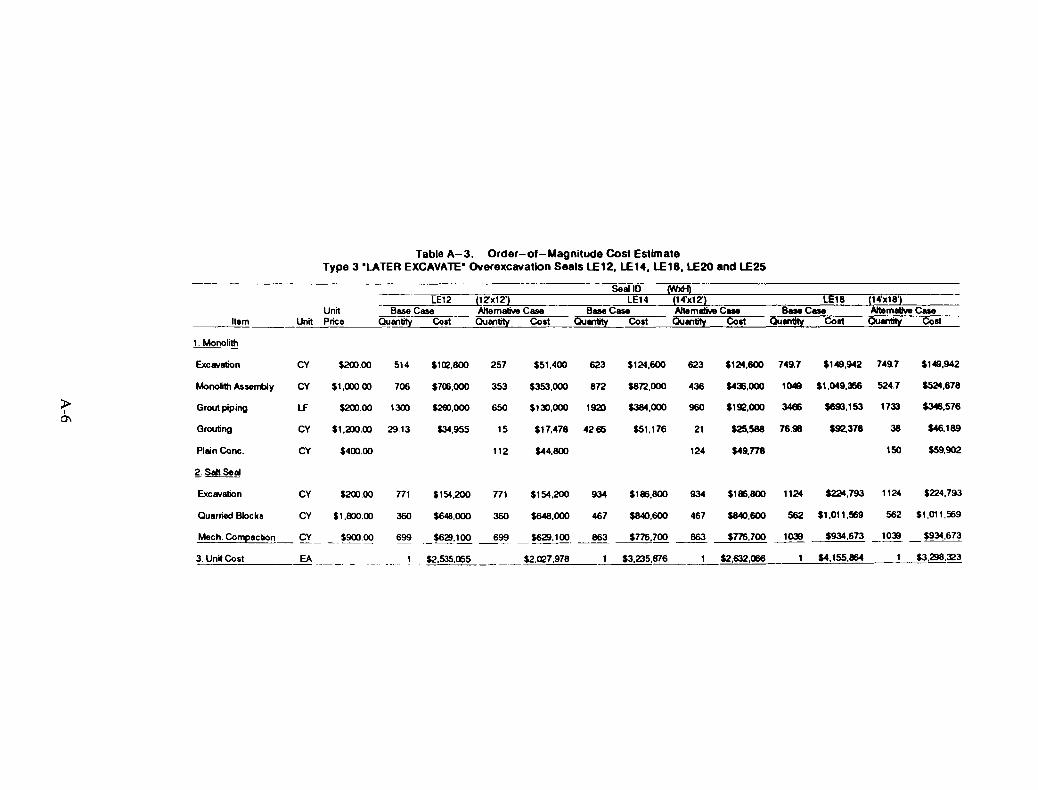
Table A-3, Order-o'-Magnitude Cost EstimateType 3 "LATER EXCAVATE" Overexcavatlon Seals L.E12. L.E14, L.E18, L.E20 and L.E25
--------- ---
Item
LE12Unit Base Case
.::U:.::nit"--:...P:.::ric=.:e'-----_---""Oulll1tiiY=:=;Co~st~
(IZxI2')A1temalMl Case
Qulll1tity Coat
SeellDLEt4
B_CaseQulntity Cost
LE18
Qulntity Coat
(14'xI8')Altemlllve CueQuantity Coat
1. Monoli1h
$200.00 1300
$1,200.00 29.13
$130,000 1920
$17,478 42.65
$44.800
$124,600 749.7 $149,942 749.7
$436,000 1049 $1,049,366 524.7
$149,942
$524.678
$346.576
$46,189
$59.902
38
150
$92,378
$693,153 1733$1912,000 3486
$25,588 76.98
$49,n8
21
124
436
960
623$124,600
5872,000
$384,000
$51,176
623
872
$51,400
$353,000
15
112
353
650
257$1Q2,8OO
$700,000
$2ro,OOO
$34,955
706
514$200.00
$400.00
$1,000.00
Lf
CY
CY
CY
CY
Plain Cone.
Exc8\lation
Monoli1h Assembly
Grou1 piping
Grouting
:>I
0'1
Ouarried Blocks
CY
CY
$200.00
$1,800.00
771
360
$154,200
$648,000
771
360
$154,200
$648,000
934
467
$186.800
$840,600
934
467
$186,800 1124 ~,793 1124 $224,793
$840,600 562 $1,011,569 562 $1,011,569
Mech. Compaction $934,673 _1~ _ $934,673$77'6,700 1~
~$2~,63=2~,066=-___=____~$4~.~155=.864=__'_____=__~$3,,298,323$3,235,8761 _ $2,535,a>5 $2,027,978
CY ~9lXlQQ
3. Unit COs:.:,t EA

Table A-3. Order-of-Magnitude Cost Estimate (Continued)Type 3 "LATER EXCAVATE" Overexcavation Seals lE12, lE14, lE18, lE20 and lE25
Seal 10 (WxH)LE20 (2O'x12J LE25 (25'x12J
Unit Base Case Alternative Case Base Case Alternative CaseItem Unit Price Quantity Cost Quantity Cost Quantity Cost Quantity Cost
1. Monolith
Excavation CY $200.00 1011 $202,200 505.5 $101,100 1405 $281,000 1405 $281,000
> Monolith Assembly CY $1,000.00 1473 $1,473,000 736.5 $736,500 2094 $2,094,000 1047 $1,047,000I-l
Grout piping LF $200.00 3150 $630,000 1575 $315,000 4715 $943,000 2358 $471,500
Grouting CY $1,200.00 106.4 $127,714 53 $63,857 192.4 $230,923 96 $115,461
Plain Cone. CY $400.00 231 $92,444 344 $137,n8
2. Salt Seal
Excavation CY $200.00 1517 $303,400 1517 $303,400 2108 $421,600 2108 $421,600
Quarried Blocks CY $1,800.00 751 $1,351,800 751 $1,351,800 1068 $1,922,400 1068 $1,922,400
Mech. Compaction CY $900.00 1459 $1,313,100 1459 $1,313,100 2074 $1,866,600 2074 $1,866,600
3. Unit Cost EA $5,401,214 $4,277,202 $7,759,523 $6,263,339

Table A-4. Order-of- Magnitude Cost Estimate,Type 4 Rigid Sleevel Overexcavation Seals HAlLE14
Seal 10 (WxH)NFVLE14 (14'x12'&2O'x12')
Unit Base Case Altemlllive CaseItem Unit Price Quantity Cost Qusntity Cost
1. Rigid Sleeve
Steel (100 ksij TON $10,000.00 127 $1,270,000 64 $635,000
Precast Conc. CY $400.00 170 $68,000 85 $34,000
Cement-based Grout CY $1,500.00 31 $46,800 16 $23,400
2. Monolith
Masonry CY $400.00 26 $10,400 13 $5,200
CIP Concrete CY $400.00 79 $31,600 39.5 $15,800
Prepack Conc. CY $900.00 348 $313,200 174 $156,600
St. Bulkhead (36 ksi) TON $6,000.00 27 $162,000 13.5 $81,000
Plain Conc. CY $400.00 143 $57,244
3. Salt Seal
Excavation CY $200.00 934 $186,800 934 $186,800
Quarried Blocks CY $1,~.00 467 $840,600 467 $840,600
Mech. Compaction CY $900.00 863 $776,700 863 5776,700
4. Unit Cost EA $3,706,100 $2,812,344
A-8
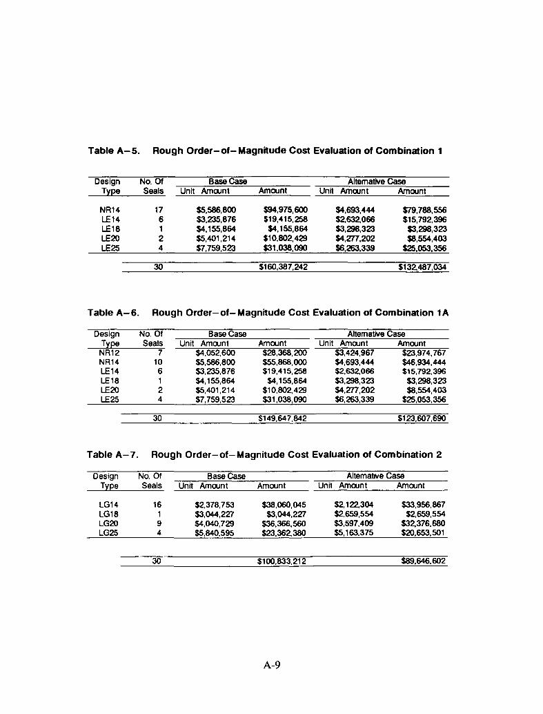
Table A-5. Rough Order-ot- Magnitude Cost Evaluation ot Combination 1
Design No. Of Base Case Altematlve CaseType Seals Unit AmOomt Amount Unit AmOomt Amount
NR14 17 $5,586,800 $94,975,600 $4,693,444 $79,788,556LE14 6 $3,235,876 $19,415,258 $2,632,066 $15,792,396LE18 1 $4,155,864 $4,155,864 $3,298,323 $3,298,323LE20 2 $5,401,214 $10,802,429 $4,277,202 $8,554,403LE25 4 $7,759,523 $31,038,090 $6,263,339 $25,053,356
30 $160,387,242 $132,487,034
Table A-5. Rough Order-ot-Magnitude Cost Evaluation ot Combination 1A
DesignTypeNR12NR14LE14LE18LE20LE25
No. OfSeals
7106124
30
Base CaseUnit AmOomt
$4,052,600$5,586,800$3,235,876$4,155,864$5,401,214$7,759,523
Amount$28,368,200$55,868,000$19,415,258
$4,155,864$10,802,429$31,038,090
$149,647,842
Altematlve CaseUnit AmClJnt Amount
$3,424,967 $23,974,767$4,693,444 $46,934,444$2,632,066 $15,792,396$3,298,323 $3,298,323$4,277,202 $8,554,403$6,263,339 $25,053,356
$123,607,690
Table A-7. Rough Order-ot-Magnitude Cost Evaluation ot Combination 2
Design No. Of Base Case Altemative CaseType Seals Unit AmClJnt Amount Unit AmClJnt Amount
LG14 16 $2,378,753 $38,060,045 $2,122,304 $33,956,867LG18 1 $3,044,227 $3,044,227 $2,659,554 $2,659,554LG20 9 $4,040,729 $36,366,560 $3,597,409 $32,376,680LG25 4 $5,840,595 $23,362,380 $5,163,375 $20,653,501
30 $100,833,212 $89,646,602
A-9
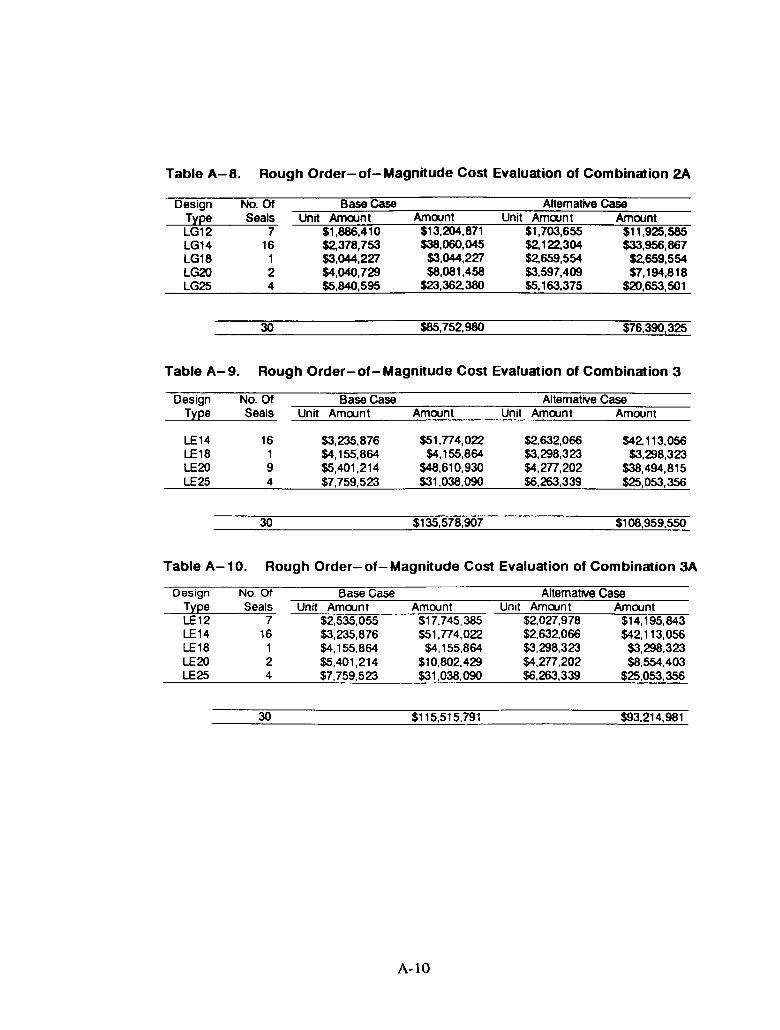
Table A-8. Rough Order-ot-Magnitude Cost Evaluation ot Combination 2A
DesignTypeLG12LG14LG18LG20LG25
No. OfSeals
716
124
30
Base CaseUnit Amount
$1,886,410$2,378,753$3,044,227$4,040,729$5,840,595
Amount$13,204,871$38,060,045
$3,044,227$8,081,458
$23,362,380
$85,752, 980
Altemative caseUnit Amount Amount
$1,703,655 $11,925,585$2, 122,304 $33,956,867$2,659,554 $2,659,554$3,597,409 $7,194,818$5,163,375 $20,653,501
$76,390,325
Table A-g. Rough Order-ot-Magnitude Cost Evaluation ot Combination 3
DesignType
LE14LE18LE20LE25
No. Of Base Case Altemative CaseSeals Unit Amount Amount Unit Amount Amount
16 $3,235,876 $51,n4,022 $2,632,066 $42, 113,0561 $4,155,864 $4,155,864 $3,298,323 $3,298,3239 $5,401,214 $48,610,930 $4,m,202 $38,494,8154 $7,759,523 $31,038.090 $6,263.339 $25,053,356
30 $135,578,907 $108,959,550
Table A-10. Rough Order-ot-Magnitude Cost Evaluation ot Combination 3A
Design No. Of Base Case Altemative CaseType Seals Unit Amount Amount Unit Amount AmountLE12 7 $2,535,055 $17,745,385 $2,027,978 $14,195,843LE14 16 $3,235,876 $51,n4,022 $2,632,066 $42, 113,056LE1a 1 $4,155,864 $4,155,864 $3,298,323 $3,298,323LE20 2 $5,401,214 $10,802.429 $4,m,202 $8,554,403LE25 4 $7,759,523 $31,038,090 $6,263,339 $25,053,356
30 $115,515,791 $93,214,981
A-lO

Table A-11. Rough Order-of-Magnitude Cost Evaluation of Combination 4
Design No. Of Base Case Altemative caseType Seals Unit Amount Amount Unit Amount Amount
NRlLE14 17 $3,706,100 $63,003,700 $2,812,344 $47,809,856LE25 4 $7,759,523 $31,038,090 $6,263,339 $25,053,356LE14 6 $3,235,876 $19,415,258 $2,632,066 $15,792,396LE18 1 $4,155,864 $4,155,864 $3,298,323 $3,298,323LE20 2 $5,401,214 $10,802,429 $4,277,202 $8,554,403
30 $128,415,342 $100.508,334
A-ll

A-12
APPENDIX B
B-1

B-2

Table B-1
Bentonite Layer Seal & Emplaced Salt Seal
Order-of-Magnitude Capital Cost Estimate for Four WIPP Shafts
Item Item Description Unit auanitity Unit Price TotalNo $ $
1 Crushed WIPP Salt CY 12000 1000 120000002 Quarried Salt Blocks (12"X12"X12" Using Rock Splitters) EA 360000 67 24120000
to 3 Bentonite Blocks (12"X12"X12") EA 80000 56 4480000I
YJ 4 Concrete CY 23000 613 140990005 Crushed WIPP Salt - Backfill in Salado Formations CY 27000 215 58050006 Lean Concrete CY 5500 538 29590007 Earthen Bcckfill CY 16700 30 5010008 Remove Concrete Liner ($75000 per day/25' per day) LF 1300 3000 39000009 Scaling Excavation Wall CY 11200 540 604800010 Grouting LF 1100 3300 363000011 Subtotal- item 3 thru item 10 41422000
Total A Item 1 + Item 11 (Bentonite Layer Seal & Crushed WIPP Salt) 53422000Total B Item 2 + Item 11 (Bentonite Layer Seal &_Quarried Salt Blocks) 65542000
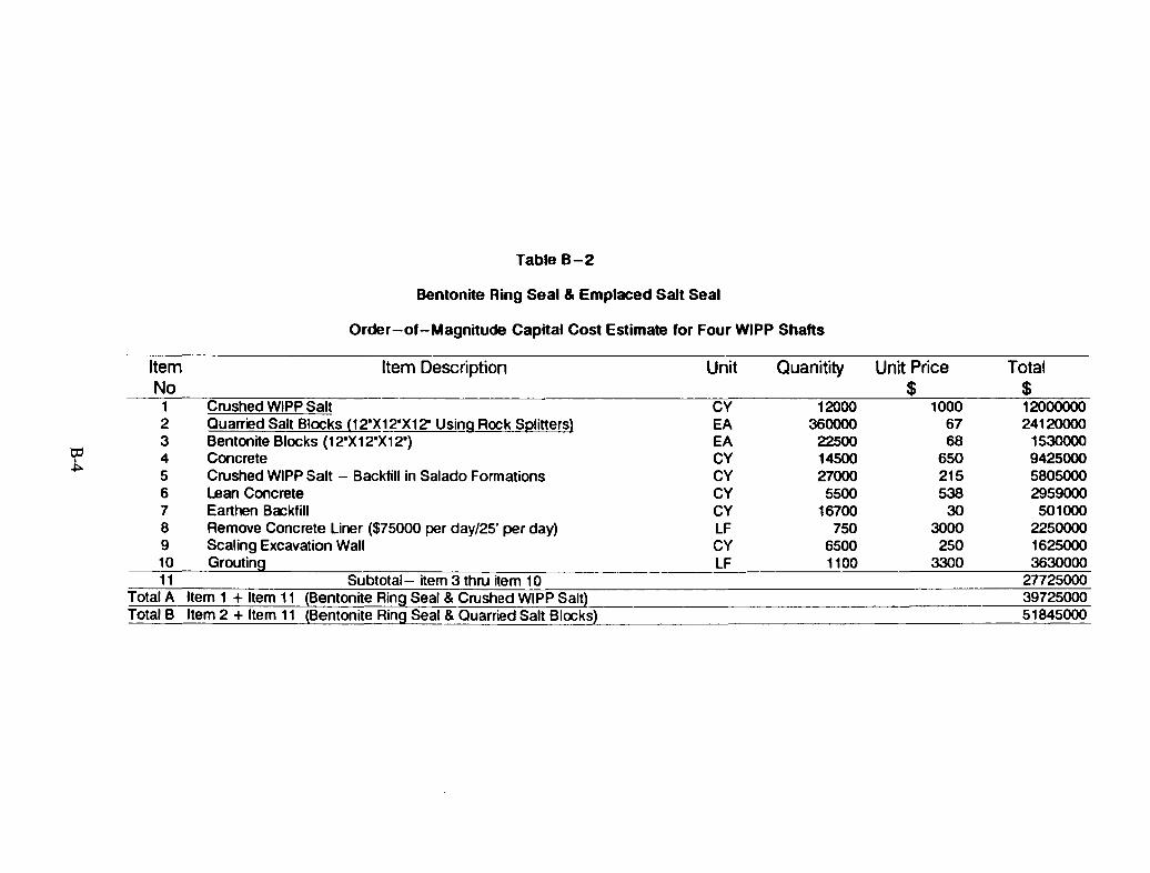
Table B-2
Bentonite Ring Seal & Emplaced Salt Seal
Order-ot-Magnitude Capital Cost Estimate tor Four WIPP Shafts
Item Item Description Unit Ouanitity Unit Price TotalNo $ $1 Crushed WIPP Salt CY 12000 1000 120000002 Quarried Salt Blocks (12"X1 ?"X12" Using Rock Splitters) EA 360000 67 241200003 Bentonite Blocks (12"X12"X12") EA 22S00 68 1530000
tp4 Concrete CY 14500 650 9425000,
~5 Crushed WIPP Salt - Backfill in Salado Formations CY 27000 215 58050006 Lean Concrete CY 5500 538 29590007 Earthen Bockfill CY 16700 30 5010008 Remove Concrete Liner ($75000 per day/25' per day) LF 750 3000 22500009 Scaling Excavation Wall CY 6500 250 162500010 Grouting LF 1100 3300 363000011 Subtotal- item 3 thru ~em 10 27725000
Total A Item 1 + Item 11 (Bentonite Ring Seal & Crushed WIPP Salt} 39725000Total B Item 2 + Item 11 (Bentonite Ring Seal & Quarried Salt Blocks) 51845000

Table B-3
Chemical Ring seal & Emplaced Salt seal
Order-of-Magnitude Capital Cost EsllmaIB for Four WlPP Shafts
Item Item Description Unit Quanitity Unit Price TotalNo $ $
1 Crushed WlPP Salt CY 12000 1000 1200000O2 Quarred Salt Blocks (12"X12"X12" Using Rock Splitters) EA 360000 67 241200003 Dow Chemical Seal Ring EA 24 250000 600000O
tI:l 4 Concrete CY 14500 613 8888500IVI 5 Crushed WlPP Salt - Backfill in Salado Formations CY 27000 215 5805000
6 Lsan Concrete CY 5500 538 29590007 Earthen Backfill CY 1660 30 498008 Remove Concrete Liner ($75000 per day/25' per day) LF 750 3000 22500009 Scaling Excavation Wall CY 6500 540 351000010 Grouting LF 1100 3300 363000011 Subtotal- item 3 thru item 10 33092300
Total A Item 1 + Item 11 (Chemical Ring Seal & Crushed W1PP Salt) 45092300Total B Item 2 + Item 11 (Chemical Ring Seal & Quarred Salt Blocks) 57212300
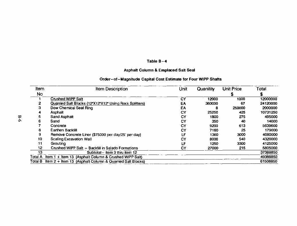
Table B-4
Asphalt Column & Emplaced Sah Seal
Order-a.-Magnitude Capital Cost Estimate 'or Four WIPP Shafts
Item Item Description Unit Quanitity Unit Price TotalNo $ $1 Crushed WIPP Salt CY 12000 1000 120000002 Quarried Salt Blocks (12"X12"X12" Using Rock Splitters) EA 360000 67 241200003 Dow Chemical Seal Ring EA 8 250000 20000004 Asphalt CY 25250 425 10731250
o:l 5 Sand Asphalt CY 1800 275 495000I
0\ 6 Sand CY 350 40 140007 Concrete CY 9200 613 56396008 Earthen Bockfill CY 7160 25 1790009 Remove Concrete liner ($75000 per day/25' per day) LF 1360 3000 408000010 Scaling Excavation Wall CY 8000 540 432000011 Grouting LF 1250 3300 412500012 Crushed WIPP Salt - Backfill in Salado Formations CY 27000 215 580500013 Subtotal- item 3 thru item 12 37388850
Total A Item 1 + Item 13 (Asphalt Column & Crushed WIPP Salt) 49388850Total B Item 2 + Item 13 (Asphalt Column & Quarried Salt Blocks) 61508850

APPENDIX C
C-l
C-2
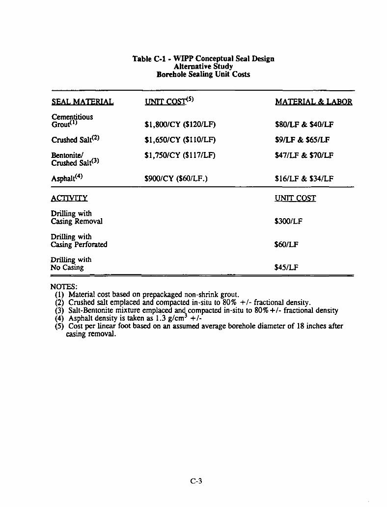
SEAL MATERIAL
CementitiousGrout(l)
Crushed Salt(2)
Bentonite!Crushed Salt(3)
Asphalt(4)
Table C-l - WIPP Conceptual Seal DesignAlternative Study
Borehole Sealing Unit Costs
UNIT COS,.<5)
Sl,SOO/CY (S120/LF)
Sl,6S0/CY (S110/LF)
S1,7S0/CY ($117/LF)
S900/CY (S60/LF.)
MATERIAL & LABOR
SSOILF & $40/LF
S9ILF & S65/LF
$471LF & S70/LF
S16/LF & S34/LF
ACTIVITY
Drilling withCasing Removal
Drilling withCasing Perforated
Drilling withNo Casing
UNIT COST
S300/LF
S60/LF
S4S/LF
NOTES:(1) Material cost based on prepackaged non-shrink grout.(2) Crushed salt emplaced and compacted in-situ to 80% +1- fractional density.(3) Salt-Bentonite mixture emplaced and compacted in-situ to 80% +1- fractional density(4) Asphalt density is taken as 1.3 g/cm3 +1-(S) Cost per linear foot based on an assumed average borehole diameter of 18 inches after
casing removal.
C-3
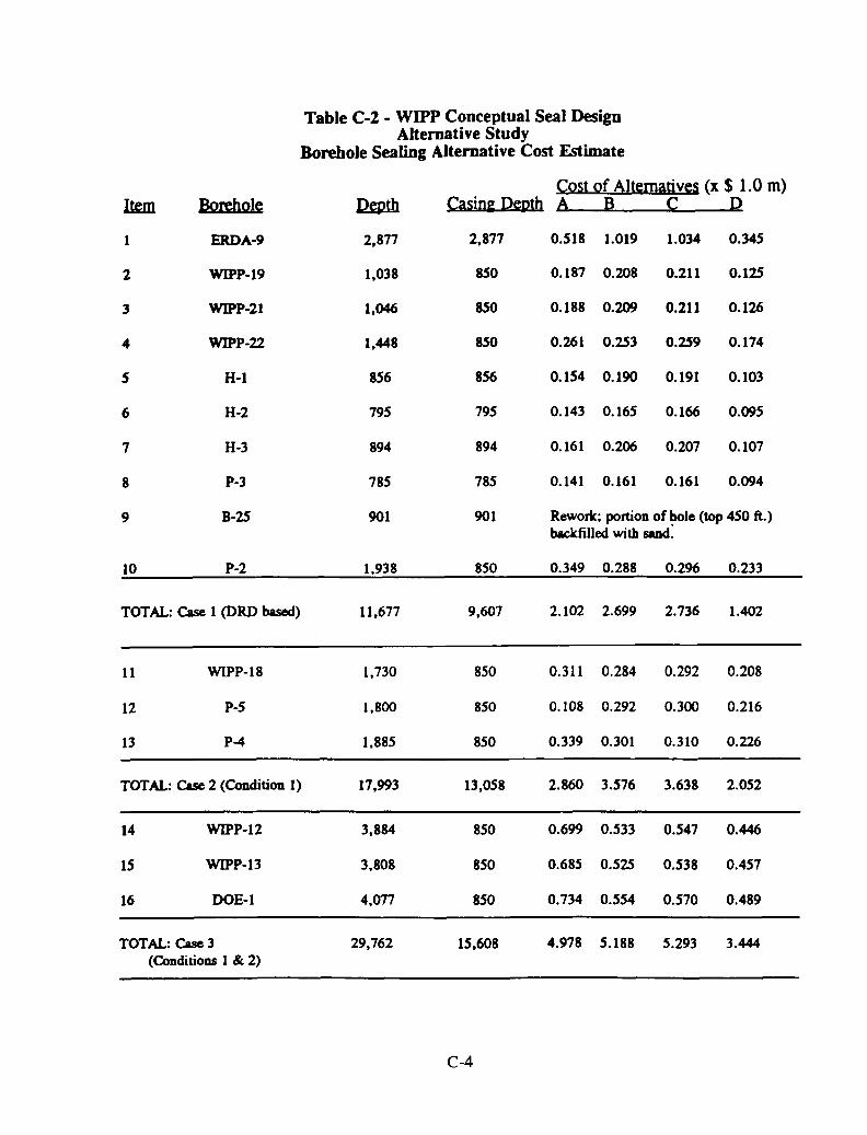
Table C-2 - WIPP Conceptual Seal DesignAlternative Study
Borehole Sealing Alternative Cost Estimate
Cost of Alternatives (x $ 1.0 m)Ilml Borehole lmUh Casin~ Depth A B C D
1 ERDA-9 2,877 2,877 0.518 1.019 1.034 0.345
2 WIPP-19 1,038 850 0.187 0.208 0.211 0.125
3 WIPP-21 1,046 850 0.188 0.209 0.211 0.126
4 WIPP-22 1,448 850 0.261 0.253 0.259 0.174
5 H-l 856 856 0.154 0.190 0.191 0.103
6 H-2 795 795 0.143 0.165 0.166 0.095
7 H-3 894 894 0.161 0.206 0.207 0.107
8 P-3 785 785 0.141 0.161 0.161 0.094
9 B-25 901 901 Rework; portion of~ole (top 450 ft.)backfilled with sand.
10 P-2 1.938 850 0.349 0.288 0.296 0.233
TOTAL: Case 1 (ORO based) 11,677 9,607 2.102 2.699 2.736 1.402
11 WIPP-18 1,730 850 0.311 0.284 0.292 0.208
12 p-s 1,800 850 0.108 0.292 0.300 0.216
13 P-4 1,885 850 0.339 0.301 0.310 0.226
TOTAL: Case 2 (Condition 1) 17,993 13,058 2.860 3.576 3.638 2.052
14 WIPP-12 3,884 850 0.699 0.533 0.547 0.446
15 WIPP-13 3,808 850 0.685 0.525 0.538 0.457
16 DOE-l 4,077 850 0.734 0.554 0.570 0.489
TOTAL: Case 3 29,762 15,608 4.978 5.188 5.293 3.444(Conditions 1 &. 2)
C-4

APPENDIX D
D-1

D-2
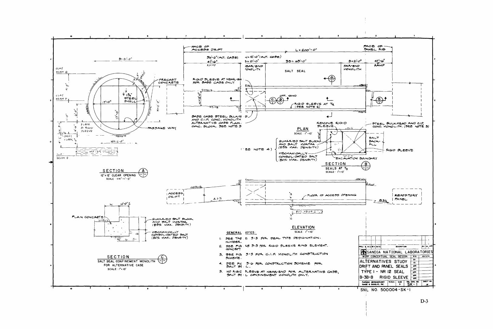
to II
eo: ZI'-O"--------!}fI'·(," (AL.i. Cfo'~ eo)41·1.~~
L.cwo'-o"
,.J:.1.z'-0"( ....~"T". e,t..~e)
~: ~I'-O"
I'fS\t I
l-.:asr I- ----1
---I
~AL.-T
~
FIL..L,..
-~ -
Fi"\f'l,.-e:ND ~""p
MCIIIOl.-ITH
L
SEALS AT TsSCALE: 1""0'
SECTION
~eMovE RI""D~l.-e.evE.
PLAN
SALT SEAL
SCALE: 1"·,0'
1GllAA,,-"'-leD ~~T ~AND ~AI--T ,'<10~"T"""~
(f:)'5% I<'1A)(. :7eN~rT"()
/V1 oc.HAN ICALL-'(<::ON501-1 ""'TeD ~Al-T
[t>or" M~. DE:N~I-r'T)
-/71'- X I OPP. >iAND
,/ ~II ®®t /l-IGrID ~L-E:eVS AT TR-(~~e: NOTe '2.)
I 'e:e NoTE: 4-)
/l-IOrIO ~L-e:eve AT Ne.a.~-I!<~"- ~A~e ~e: ONI--'T
A
-::-"}II';lJI,:;:;"~
SECTION
r-: I~.
-~II
=
o
WI P CONCEPTUAL SEAL DESIGN •.0. ••••,..
ALtERNATIVES STUDY i------=-=--:--I-----~
DRifT AND ~NEL SEALS ::rfPE I - NR 12 SEAL I-_=-.:..:...j.---t
8-38-8 RIGID SLEEVE
-'-PROJ w.o A(v OAl[ 0l~T1~ . 8'( Q(J":'
SANDIA NATIONAL LABORATORIE
SCALE I" -10'
ELEVATION
---~
',,-/ I
,/'~:- -- - - 'l----
GENERAL IOTES:
II
1. ~ee "T"Ae _ e ~-3 fr:?f/... ~e:A1- "'N'pe; :7ee'IC::oN,AiION •NLJ/V1eeR.
'2. ~ee ~Ia... ,e ~-3 fO~ ~GlIO ~L.-eeve Ii.IN~ eL-E:tv1e,...r.~NCer'T
~. ~e:~ fiG! ~-5 ~Ol&... C..I.P. MONOL,..ITr1 c.o~TR.LJCTI"N
5ct-ter<1e. .
4. ~ee F'I< ~-(p fi::l1'.. CON~R.uC:rION ~r1eMe fI:'''~AL,..'T ~e ' .L-.
5. NO "'tOrle 'L,..e:eve AT N~-E:>ND r't::'~ Al-ieIi.NAi'VS. CA5e.~L.-T ~e ' L- C4'NF-INE:>MeNi ~ONOL_J"T"ti ONL.'1'.
~r - - - ---r-"I ,ACGo~~~1
I ""-IFi Il J_- -
.!1...
'"',.- ;
;;t----''-'---=-~
SECTION C
12' x 12' CLEAR OPENINGSCALE -- 1/4" .,' - 0"
SALT SEAL CONFINEMENT MONOLITHFOR ALTERNATIVE CASE
SCALE: I"' 10'
to
A
c
D-3
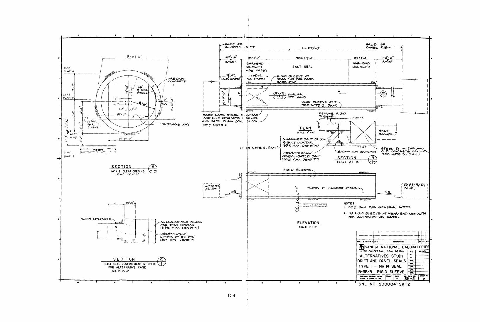
A
SNL NO· 500004 SK 2
D I • I a I I I •
~ce. ~,.
III~T - L.= 2100'-0" I'"ANeL.. ~Ie.
~"Z ~'.c?' "eo=- ",.,' -0" e.-ZJ'.O· 4~'_"''' •! AR,.-eNO 1"I""l'-I!'JNO IV'Mt"
, NOl-lTti SALT SEAL P<'1ONO L- 11''H",~e c:;o.~e)
1N~14'-o"r:IC31IO ~L.eeVe ~',a:l". ~e) N~eNO f"l:l~ """~e. (r Iu·!:t,L eA.~e. <:>NL."'I" _lEAF I
r--- -~ liii I~
UI
, I L- -@ I
.""/ I ~~IMIL.A~ I
/:-~I=== .:::>",.. I'lANO
I •~1a.IO 'L.eeVe: Ai T 1
I(,ee NC'T"e ~ J ~",,-I) t=1~IJ" I I• ,~ 7 T "I'i1'iiIFi'" I I~eMove. ~ICrIO ¥
IiE:AO~ VE" ;1111=1111 ..• OL.-I"Tl'i. I-
L.OCI'\,.. "[FB;[>(----~PLAN/ ,AL-"i 1
SCALE I" 10' ~ l-~ ~- . r-'L.L.'
c.l.~~leO ~L.T e.~YA1 U;;: \' - - --:*~L.T MOl'TA~ • n---;.~ NOTe 4, ~I<.-I ) (~r" ,...,"""". C7eN~~) C '''1-'''1/= T ~ r1~ """- .. ~ eeL.--- U'o- 0
loti eCJ-tA N I CAL.-\..--( e."~ATION eOlJNOAR'( C.IJ'", C<:'NC~e: MONOl-I"".(~e.e NCTe~, ~K-I)
C-c:'I'l50I-IDATE,O ~L.T SECTION @ceo,:, ~~. ~N51T'T')SEALS AT Ts
1'--1<3110 -5L.-E;eve. "" "=.~.. ~,'II ,'''',,,_
l- ---?...........,
, /' Ir~ep~T-fo".q-1
-~~ - fL.-Oo~ OF- ""'-Ce~~ OP~IN~. I "ANe:L.- I-~
~I I
--_.~.--_._-_._-_._-- I IL _____ ..J
1"~'-', •...T ~i...,;;;:r;r-- '--. flrll'_l --"'L NOTES:., 1= -=Me.I~"!~~
I. ,ee ~-I 1"-01' ~eN~ NC1T65.""!!-~;
~. NO R.JC!lIO ~L-E;eve, Ai l'oleAtlo.- ~ND MONOL.-I~
r't''''' AL.-T~N~I\1e. ~e_•
ELEVATIONSCALE: :', 10'
I I-~~_.- ----- "-1 .
I---- 1-1----· --I-- -I .1-"'0.1. eo w.o~v OAT~ __ ._ Olsat1P'TIQIiI _~~I~
~SANDIA NATIONAL LASaRA TORIE~W[PP CONCEPTUAL SEAL DESIGN ••0. "'~11"
ALTERNATIVES STUDY "'oc.
DRIFT AND PANEL SEALS_._.
I TYPE I - NR 14 SEAL -.I8-38-8 RIGID SLEEVE
_., _.I .- ...-- ISCALE, I SIZE
.. DWG. 110. SICE' 110-_ II 0CUGl.~s. lilt. 0 SK-2 ~
I • I • , - -
(: '
(~e;~I C?,",I~I I
I IL ..1
(A~T.~)
r-+--rI I
I I "I I ?I I -~
I I •I
~--.J~e ~e. ,-reeL.-- " .~NO C.I. Po .:;e>NCfl..e:."1"e I,
AI-T. CA~e. /"'L.-AIN COf'oI'S'ce 1'ol00e 2.
6lup..~ill-lep-~", ~L-OCA<...
ANO ~AI--r 1V1.:::>"T'-'~(~~~ /<1~)C.. t:'eN~rrf)
/<1eCl'iANICALL:(Ct?N'OI-I!A"'Te>O ~I-i
(f,oY; I<1Al(. DE:N~,T-(.l
.._--/
A
SECTION CSALT SEAL CONFINEMENT MONOLITH -
FOR ALTERNAnVE CASESCALE: I" '10'
10
-':ff, tlf
to
SECTION
+
14' X 12' CLEAR OPENINGSCALE: 1/4" 1'- 0"
II
t-~A1 I;";?E':,:,A,:"M--.:.tl~ ! ,
.1
c
D-4

~-
ID.:. -=~
: I-t-_··· -.----.-.. ------ -~-+j.-
._;-+---1-- -1---- .--------I-~·-...~, ~ W.O REv OAT( IXscal"TICJIrI IY 0] aJIfJ
r~JSANDIA NATIONAL LABORATORIESW[PP CONCEPTUAL SEAL DESIGN .... ,~·~'74
NOTES:
f. gee- ~-li ,,",,'" c:3re-N~ NO'Te:C5
~. TrlE: L-E.Nq!lT"" E:ol<.CeE:oDec;;> L...E:NGlTl-l 2OO~.cr=- Ttote e.N'T~NCS o"'I~T 'To'T1"tE: P',ANE:.l...-
3. NO "'I~ID 1~L...eeve AT NeAA..- eNO MOPljOL...liI'l1"0"- ,Al.--T~NA'TNe CA~e:_
ELEVATIONSCALE I'" 10'
.Il:::lo ,,=..U,- -'11
~L.~.~..,.--:=-o-~==.\...E=--~.. r-1I:'I~"1 ?"C- .. )
!It
I___. ...-- _P_l.-_OO_"_. ~_F_,A_cc._e_'_'_OP_e_N_IN_~~. --+-..c~
~ L-
I
1
--J---- II~ ~l.__
I
e ,A ~e CA~e: 'Tee.L ~L""I'iCA~~e.I.~. e.;,NC. to10,"""LI"""
~ ,L1'. GA'3>e. r"'L.AIlOooj c::<1NC.e.L-GlCk",
~~ee NOT~ ~
--~J--------.:..-I-----------------------1'1', ..,d,..- -I/1
~// I@\® eIMIl,..A~/t" '- IIQ57 W OPP. rlANO
'- I-~
_ 1119'i"":' III ~"1
JlI~IIf1~ ",' I~ - - _.--------..-.,....---....-------- --
7 '_ II
--.°111"'-., ".;
L~I/II~"---FiJ''L.-
<:>' ~ I....?: I
'ii' ",,' 'f------/--
I
(- ---.,
IA~I ~1t'~'~T I -
~ ~L J_'--
•L
~eG1iANICAl,..L"'(
~N~LoIC',AT~C;;> ~'T
(~1D JoI\A"'. Oe.~IT-o
t::I.LJ~~/i..lel:)-~A1-T ~
ANO ~l,..'T ""'O~T""""
(!>'''' IV1A'Io.· OeN~IT-()
I..
to'-d'z
SECTION A
_~~o'-o"
'-"'::::::.cc-.. ---,,-~--:,-:o._.--,II, - .,;- ._, ; ..-' •• ~.
20' x 12' CLEAR OPENINGSCALE'I/4"'I'-0"
I
I
-....
1- -= 1-
/17KIF-f r~PP"
t-"-i'- :<:>
'.. ~.L-,-IL- _
. .t=-- ~M~0L 1to" ....!, E-- :-:.. ---.:.-..- -- I7E-AM I:-
-J..__-..:1ll::....---J...---..:.---....J----8.:...---..L.-------:-:-:=-::------ i ",:8:",, J..I ·=- .JI ~I ..L.1 ~2---.....lI.....P"7'=";:c~e:-::c;:,.:----+
f"l'ce or-- ~Ne:'- ~Ie.,Aeces~ ~Ie. L-1I1~ ~ -2p,"'_On ('&E NOT~ ~l 'E;~ ~"_I -~Q.--" -,ee ~"'-I AI:)t"1- IN.-t>AI:)O'I- I .... P"O. !
r , --_ "'II_O~ , (J'ill, '-0' 80=-~'-0"(~ :; ::::,.....:~=::p)~-------=~:....:e.=---:.-9.'..:3~-~O=------------------t_--= .....--<7-----"t---(,-:~':r:-;-;:;----l~A/"\P N~- er C' ~-e.NO ~MP
""GlNO~IT't ei'AI-T S~A~ MONOI-ITIoi
,SECTION
SALT SEAL CONFINEMENT MONOLITHFOR ALTERNATIVE CASE
SCALE: I"" 10'
III
C
II I I
AI..;TERNATIVES STUDY:.DRIFT AND PANEL SEALS t:-~=:.=====: ~_.
TYPE 1- NR 20 SEAL 1---.:..:..'-+----1
8-38-8 RIGID SLEEVE I-==~:+--~--t
r S~L NO. 500004 - SK - 3
D-5

KEf NO.
<if
(3IFi-OVT'NG! ~e:.e"e ANI:' C'1i.Z.Cil/l..O...JT Ai"~ eNI:'~ /""Of'- e>A~e
~~e, Ai" ~-e~o ONl-"( '""'",A1...:1"e"-NA'ilve:. c:A~e ..
SNL N~ 500004-SK-4
ALTERNATIVES STUDY ~ ---DRIFT AND PANEL SEALSTYPE 2 - LG 12, 14, 18,
20,25 SEALS81-382-81 GROUTING SLEEVE
1' t i -_____ -I _ Ll I
PRO..I, '" w..~1~v o.~j DUCltIP'_lo. ._. _ d.~·l·"
;r. SANDIA NATIONAL LABORATORIEW(PP CONCEPTUAL SEAL DESIGN w.o. ..-~,14
,I
/
fl\ I
I
\
~ee FIC>'. ~-w,ft7I'. ~L-T ~I!!;AL
~N~T~u,-,TION
~,-,"1elll1E.. ---
PLANSCALE; NONE
ELEVATIONSCALE: I"' 6'
•r
//
/(14'-0")[~'-O"){~'-O"}
(I"",'-C" )
/l"I
SECTION
()I
SCALE; NONE
l~~~C;-~~=
SECTION
::;>"-I,aT0:::1-0':;"
._----
Cl-A'(~E:AM e~ _
+--lO---,.----,--~-...,....----;--~--:--f
D-6
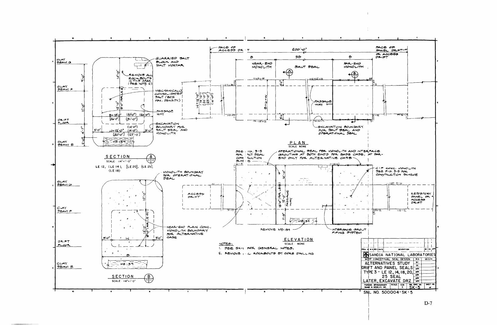
to II
Co I,.. <::.oNC, ""C"-lOL.~
~I!:>e FI"'- 3-:; F~~~1"~i,o.... ~'->1E.w1E
-,--' - --~- . - ---- - - ..-- - j-- :.__ - - I-PAQ", .W.O~~D.T_(_. .I)(~~IOJI 81'~."l~
SANDIA NATIONAL LASORA TORIE
II
- - - - - - -+-"'-==~-i 1------1
~-ihl
""',, o=--: ~orP'''P~" - pA.Nel- Of'.-
I IACCe~I C'''IFT
------~~,=="'~_~~I-------l----r:..---i '11== I'I=-.
'Ni~~ OrI"<::lUT ip'IPINC!! "Y5'relv1 I
PLANSCALE' NONE
~f"eF/.ATIONAL- ~eAL. F'~ !'I'10NOI,..IiH AND INT~r-A.c.e
ar~L"jTINCil ,AT et:rrH eNO~ ~~ ~~e CA~c, ~T ~~~O ONl-"l' POFl.. ,AL-TeFl..N,...iIVe. CA~e
(I
~ee I l<:t. ~-5
f'c:>"- '''-I.-, ~eALCON! ' "u",TIO"'l~He ' IE: -.--
;'=-11 ='"
_ l~f;I·
-ji"e:iE"
ELEVATIONNO'TE6-. SCALE' NONE
1. ~e;;e:. ~I(,-I ~fl... CloreNe~L. N~.
~. fa-eMove , ' .L. "O~~OL.T~ err co"-e OIl-ll-l-IIIlG
.iL::::,----II c.ce~~
C' 'F'II I'- J
NEA~' 61'olO PL-AIN CONe_MONOL-I"TM ~NC'A~"'(
/"1:'''- AL,eJ'NAT,vS~e:
- MONOL-ITH ~L.lN~"-r
fZ::'~ or:'e~i'IONA.I
t'E::AL.
CAVATIONeol,.lNC;>AJ'.l' F"'pF/..'5..... I..oT ~eAL. A/oO~ONOl-ITH
6lLJA~~IE::P ~L-T
!!!'~""'''''NP9""'l-T /oo'10~T~~= 1
-~ f-~ '-.I'f.e::.N1ove
"Glc::-"'-I'O~T~IN THI~ AIlEA(~~~ '~~ '2)
?=- - ---=- \III I
I
I(---~- "'I A .' ~ II ~ -l II = I
1:)-
I -~~
-----"TO------~-_!_F'.A5~e
WAr
-,S=-SC-=~=-LE.::;C_T:""1/4.:..1,.-=~....:,~..:.o-"------.,@
~"O" I
LE 12, (LE 14 J, [LE 20], {LE 2~},(LE 18)
-'
-'If""
OJ;l,IFT... CJC"-....
3'-0",-~
Ci-A"f0 ~E:AIV1 e
D-7
NO. 500004-SK- 5
WI P CONCEPTUAL SEAL DESIGN w_o. ....".
AtTERNATIVES STUDY f--'~=-1,-+---tDRifT AND PANEL SEALS 1-_-'---+,-----tTTE 3 - LE 12, 14, 18,20,1--"-'.-+-__ t
25 SEAL 1-':-'=:-'+--------1-,LAiER EXCAVATE DRZ I-_=,-+---
II
SECTIONSCALE, 1/4""1"0"
to

to
= ~~'-O", -I"'''' ""-a" ~~'_O"~~'-O" ~ - '2.' II eo e>1Z,:' (,0 -0' ,"", .....""
1o---1r--~-A-M-f'--"*"---,I--,-- . ~·l=---------~::'~":L:~:r~~';:'e.A":"'--I..=-p.:."-:T=-=T~;------------if'I--P.-A-'-~-_-c-NO--+-----;:;pl..A~---,P----~
NE:-A"- , " NlONOl-ITiolI'<'IONO\",,'
"ff:: II ~-.
A
J
~-- - ~d'j
I '
~,; ~~vl~" _~~ ~sco.."...==- __ i"' "'; ....'" SANDIA NATIONAL LASORA TORIEWIPP CONCEPTUAL SEAL DESIGN w,o. ..·.'70
________ 1-__---=::::..:'~'-=_o:_'_":..::"2::.._'--=-.: -,
lc
- --- _. -- -- -_. -4-----"'~"~,,~,,~c=:------.J
No"e~'
I. ~ee ~""-I PO"" ~"'NePl.AL.- N~e~.
:2.. I"-e,N101/E:. ~cte-.eOL-""~ e.,- c.o~e 1:7"'-'\""I..'N"'_
JPLAN
SCALE ,", 10'
SCALE'I"·"-O"
ELEVATION
___ ·_·_--I::1PE:>Fl-ATIONAL..!5eAL. pe" ~IGIO ~L.eevs
_------ .. AND C.I.P. Q:?NCR..e,e MONOLl"T\1 AT ~'n'l.-' ..---- E:;ND~ ~ ~~ CA~e:> M,,-eNO ~'"
,AL.'Te:~NATIVE Co'~e- 01'11.."'(.\I
)
;-flt>.b~~ e WA'i
-L _""'II
!II
,/
-t--:*--.--- - - -- ----- - -
~~I)N ~",. "FO"-Z.. I!:::')(C,AVAIION""T 5"1.1-1 ~E>AI...-
<:::1LJ"'~f'.I"'1:7 ~.,.
e.lA'0l<. ANO ""O~"'A"~SAL.- (f;~y., I.1M.17e.~ ,.,.,. )
e.O,""N :::',Af'."T' /"O~ NeAI'..- eNOF'l-A1N c.oN~e.Te ""'ONOL-'''''''f~ ,AL-'Te.Fl-NAT IV!: ~e
--,'I1e;;c"'AN ICAL-L-'T~AL-I ~=AL.-
(80% >/lAX. OE:.N~l"r(\
1
A
r
W:'14'-O"
SCALE: 1/'1'" ,'-0'
~.I - _ \:: l~ .
SECTIONWxH= 14'x12' CLEAR OPENING
~>I1~=AL.l.
~e.ol-~ ~IN -:"Hl~ A"-eA -?(~ee NOTe 2)
c~"1'-~
~E:A"'" F
(II ~
"I
"I I
3'-0'
l
_.By
(1(._._.-,
ALTERNATIVES STUDYDRIFT AND PANEL SEALSTYPE 4 - NR/LE SEALS81-382-8. ALT. I + 3
SCALE: 1/4", ,'-0"
SECTION
to
0-8

4- IO ..... ..... "-- "-- i 5 .L.-I • .L.-I • ..1II-. -..III-. ~
WASTE SHAFT AIR INTAKE SHAFT EXHAUST SHA" SALT HANDLING SHAFTo (FT) o (FT) ------
HEAR-SURFACE -'00 BARRIE R ~
; -'~&~C...UL
... :1 ;;:u .. z •c'-... " ...",-- ; """00 .... '" :I,,, ""," -'
0c~ -lli- J2L
u00 ... TOP MAGENTA
~ -'" AQUIFER C---_. =:WATER- BEARING ZONE700 SEALING SUBSYSTEM BOTTOM CULESRA .- ...- ---_. --- ]~- L ...!2!- ~ --ll!. -', ..
SHORT-TER.. SEAL---.-OU~ c
800 or.- .. 8= ~...... " BARRIER~~t~V't cu .BL ~ --»L C TOP SAlAOO F..... au ...!..qP SALADO .. -'c -!!.Q.'00 ....
~ --!QL BOT10M KEY FOUND----_. BOTIOM KEY fOUND
~ lOWER1000 CONC.'TE --->f
PlUG
1100
1200
1300
I~
:1400 ..
•I!lOO <> ez
::;~1600 ~ :I.. I
1700 ... I
~1800 or J.!.Q..Q... 1800 .!.!.2.Q....
-'•'900 ~ SHORT - TERM SEAL ;
BARRIER0'-.. -'
2000 u 4
~Z2'00
:o!!: ,~....
STATION ~ CJ~ c~~2200 ~ ,
- STATIO", PLUG
! I I _ ~ . .- I j.. J 1_)_' ...
fltK)J, a .,O~A(V ~u~j _ o(~I~TIQfII _ l~'f' 0,,""
ffiSANDIA NATIONAL LABORATORIESWfPP CONCEPTUAL SEAL DESIGN •.0. ..·.or.
ALTERNATIVES STUDY
SHAFT SEALS
LOCATION OF SEALS
8:cY_f-- .ex.-f-----.~-----.-.-.-.
10 f I I ISN L NO. 500004 - SK - 7
D-9

-+-_-=1Q:....--..L-_---=-_---J ......L- ...L.- j-+-_.:--_-L.._-.:.__J..-_-:-_-..l ~ +
w.o.
REMOVE WEATHEREDSALT (2'-0· ± RADIALLY)
!:il'~ceceen en, I
... Q
... '"il~~.~~ 0...J...:l!III
MATERIAL
QUARRIEDSALT BLOCKCOMPACTED
CRUSHED SALT
,.,;;". -" W:~J~.J~.J -r11 SANDIA NATIONAL LABORATORIEwlPP CONCEPTUAL SEAL DESIGN
o.es:!:1100 FT.
1500 FT. 0.90 !
TOP OF LONG-TERM SEAL FRACTIONALDEPTH DENSITY
13 FT. BENTONITEBRICK MASONRY(2.0 OA:IIl':t)
.'
.." " ,
~I__;O_LU_NG_
C
_
R
_
ET
_
E
_ ~...L--I~--'--..
CONC. PLUG INTHE STATION
55 FT
TIT:I~I~
'III
:~I!r-: EXISTING
en I' Z SHAFT WALLA.e... f-"
i,~'
ala:... LL
jili( I'--1
CONCRETEPLUG
CONCRETEPLUG
EXISTINGSHAFT WALL
13 FT. BENTONITEBRICK MASONRY
12.00/cm'! )
00 FT
100 FT
10FT.
...
.J ,
~;;;IOO_.!..!:.....,?... ~.....-c.:J"
ItC ..IIIU +~ ~:Q. c2""'-
\
,-_:- ,
- .-i.._ .__ 10FT.
~'---_Cp_~_NU_~_R_ET_E _
EXIST, R/CONC. KE~: fPLAIN CONCRETE "BACKFILL ::'j
r---=r CONCRETE
~l...._p_L_U_G _
,LJSTONE/HALITE
~REMOVE r
SHAF?
CONCRETEPLUG
MAGENTAAQUIFER
PLAIN COHCRE)BACKFILL---
CONCRETELL PLUG
'·1."----------8~~mo_- 13 FT BENTONITE
:=;.::::--=.=-:-=- BRICK MASONRY
'. 1 (2.0Q/cm3 ±)
Gf CONCRETE
~l PLUG , 6=,"==:/
I
f-'lL~WlLCONCRETE
'" PLUG'"
'"'' 'OW"3 I "" ~ ""RINGS f 'a'. lri SAL-ADO
EXIST. REINF. .. I :1 MEMBER
CONC. KEY ---tF1k±+-- PLAIN CONCRETE
~i..:.:'I...L BACKFILL
GROUTCURTAIN
SURFACECONCRETECAP
I\.--EXISTING~ SHAFT CASING
300 FT::
'1.JLL
I
I
11
~['" 'i- __ I
By
CIt................
ALTERNATIVES STUDYSHAFT SEALS
~--10--...,...------,--------,-----~-~--,
D-lO

to I I I I
-
-'>z...Z...uC(.J"- ...~ ;J""In... I« 0
~ ~en ~ I.OOH,Z II:l!l0...J :;:I--REMOVE WEATHERED~, t; SALT (2"0' t2· if RADIALLY)>- z00: ulL II:
~ 00..,en "olg>- ...JIII III gOOO FT
~!J"'c.J '"« ,In 0.t ..."-1-_ II:
,..~
~15~!"z...
I.-- ------1-+-1._-_---J-- -- - .-~. W.O lilly DAT( DI~TlQIlI Iv caj~
fii SANDIA NATIONAL LABORATORIESWI P CONCEPTUAL SEAL DESIGN •.0. .~·"'74
CONC. PLUG INTHE STATION
55 FT.
I
.ii-'-.
I
CO.NCRETEPLUG
TjTJi4 ..
«...JinC(, Z,"-,0,
"- ;::rEllISTINGi ~ SHAFT WALL:0 ~...
U +'«
~i~1lJ~
BENTONITE i.,.--;10R~NE~TI :'-'-~
t-' CONCRETE iN....-... ,',U:t\ PLUG .' TOP OF LONG-::: ~ . • TERM SEAL FRACTIONAL1C--I-------~('_'~..;...:."~. ...,.;--',~D~E:.':P__'T.!:H!--__..:D..:E.:.:N.::S.:.:IT~Y:_.____,:M:::.A~rr.:'E:.:.R.:..:I.:..:A..:L_
I ,::i:l',..; 1500 FT. 090! QUARRIED-I SA~T BLOCK
I1800 FT. 0.85:t CQMPACTED
~ ~ . . CRUSHED SALT
~~ I I>- to.Zz... Ill'"
_ 1000 FT.
11i=.BENTONITE10 FEET
T
>-.J«
:~EXISTING:~ SHAFT WALL... ,...i0... 'u' ' 1200 FT.
~I....I
:
~~ L..
CONCRETEPLUG
EXIST. REINF. CONC. KEf"o/\
PLAIN CONCRETE :1·BACKFILL I:
RINGS
MAGENTAAQUIFER
-r BENTONITE RING10 FEET
T
600 FT
...J ";::lL
z...:I:>-'"«...
~r.. ' LDn"
CONCRETE
PLUG
PLAIN CONCRETEBACKFILL
GROUTCURTAIN
SURFACE. CONCRETE
CAP
i;
;I~11/ILEXISTING~: ~ SHAFT CASING
ID
c
r...J z.J crlL ...
"""
~...J CONCRETE"z... lL z« PLUG0'":1:' ... >-"'>- tn Za: ...C( IIIIII"
L PLAIN CONCRETEBACKFILL
LEXIST, REINF.
"CONCRETE KEY.,
JAUTERNATIVES STUDY ~:-+---t
: SHAFT SEALS -. •LON~-TERM CONSOLIDATED SALT 1-=:::':":+-----1SHO~T-TERM BENTONITE RING f-7::-=-.+----1
I SEAL - .
to T I
•~-- SCofoU'1 SID 1 - -9110. ...' ........ • -..s. lilt. D SK - 01
I SN~ NO. 500004 - SK-9
D-II

8 I I I I
-
. -- j 1'- - - - ------ -- ±l-f~ ~~l~'v~ _=-=-~~ ';~lm,", --=tt:·~ ~r;;;JSANDIA NA TlONAL LASORA TORIES
WIPP CONCEPTUAL SEAL DESIGN ...0. ..-517&
-I-Z....~....uC..JlL~W,
~~)-~
~O~z ....~ ~~ REMOVED WEATHERED;i ~ SALT 12' -O"±
~':il RADIALLY)j: ....U U::...~~u
0,' a:"'0oI-(/)
:1\~ --!.Q:Q:Qfl-gI- IIl
;i,~1IIc<.(/)lL,!!:c~~
c'"~~
~l-------rrrri' ·,· ... b
0.8e ±
... QUARRIED-1500 FT. 0.90 - SALT BLOCK
COMPACTEDCRUSHED SALT
~REMOVEO WEATHEREDSALT 12"0" t RADIALLY}
...:.::1800 Ft
,I,I
)
II
I\
I
-J.1
1-..:...:I:"'" ~II DOW CHEN.
~~f RING 7 FEET
CONCRETE ..'~ TOP OF LONG-PLUG , . 'j . ~ TERM SEAL FRACTIONAL
I l DEPTH DENSITY MATERIAL
It
~DOW CHEM. RINGS; 7 FEET
I--EXISTING: SHAFT WALL
-
1:1
00 FT.
:
~,c<,Ill,
Q.'!• :0....U
,c<,.J ;
Q.~ ~....
ALLOY STEELPLATE 1/2"-
EXIST.REINF. CONC. K~y-q=
PLAIN CONCRETE +1'BACKFILL i,CONCRETE
l-' PLUG...oII>
RINGS
J r
ttll: I~~
II::--EXISTING
j I SHAfT CASINGiLz....:z:
:§ 1:~6°OM~GENTALAQUIFER
PLAIN CONCRETEBACKFILL
c<t i ~ CON CRETEIII .... '" PLUG'" :z: (/)
U
:\
PLAIN CONCRETE ~[: \BACKFILL .:'
-------- I' TOP Of SALTI' --EXIST. REINF. . '·1 . r"",. ",. ,,,"CONCRETE KEY f'; I :1 RINGS
:1'jL.IIf '900FT
-r..'C<w(/)
,.: .J CONCRETEu. ~ PLUG
~ i ALLOY STEEL~ PLATE 112"U
.,
~EXISTINGI SHAFT CASING
I :i
IL1.,1,1::
~'rJ'. I ;:
I
I::~\I
:z:' ~51 ,..... 1 .,
,~II t ::::$: ~\~.:--fL
i
r
[
"'rmt=.",' o,~<~,~ SURFACE" " . ,. CONCRETE. ". CAP
t: :.{';;o .' GROUT
III - i.! '"'''''
i~
ALTERNATIVES STUDY:.SHAFT SEAL 1--=_--1.~---t •
LONG-TERM CONSOLIDATED SALT l--=:-'-'..-+----SHORT-TERM CHEMICAL SEAL _.
III~------------------""'---------"T---------""----~----_~I ..,.. T'" ~"~:-='':.~~::INCIU:::::.:::s~.:":~'..l.SC_"'':''''''[~:l-IS~'~_1J..,:;S~K~QWG.,:':,,:I'::():'·..1..M~~~"-1'...
I I • T I. I SNL NO. 500004-SK-IO
D-12

•
69·!>114W.o.
REMOVEWEATHEREDSALT 12'-0·:tRADIALLY)
2000 FT.
:-I :~~T Ck, ",.
rIt SANDIA NATIONAL LASaRA TORIESWI P CONCEPTUAL SEAL DESIGN
55 FT.
CONCRETE PLUIN THE STATION
o'
SALl1 BLOCK
COMp,ACTEDCRU~HED SALT
,
0.85 ~
090~
FRACTIONAL IDENSITY MATERIAL
QUARRIED-1!l00 FT.
1800 FT.
TOP OF LONGTERM SEALDEPTH
>-,!::~EXISTING
...' !:1 SHAFT WALL
...J'"ero
:\ ':' ~A. ZA. O.i i='~~:~,e:
~ +1
t~::E ....... -
• r- DOW CHEM.-.i RING 7 FT.
I(\~:• EXISTING, • SHAFT WALL
CONCRETEPLUG
T"-',,-,,-,==,--,-KEY 9i -:-:::J.(1)'00(
~:::::mm===~._.. JSAND-ASPHALT' I
- BARRIER
R
'
:k---EXISTINGI SHAFTII CASING'.
I
~MAGENTAAQUIFER
,
I
z 700 FT.~~
...J0u
CULEBRA... AQUIFER...J00(:Z:,A.en00(
, lOa FT.
I
_.. I,. I TOP OF SALT
T. DOW CHEM. : ;.~RINGS
SALADO MEMBE
...~
oII:Cl
en::)
ot=...z'"::E'"ua:
'"......Cl:
ClziiiCl:uClz;:(I)
i<'"'">o::E
'"a:
~ EXIS ~ t'" EXIST REINF ~.! ~.:
CONCRETE KEY• • 900 FT
~------ -
SURFACECONCRETECAP
GROUTCURTAIN
~...oII>
to
ALTERNATIVES STUDYj SHAFT SEAL .... ,,_
LON9-TERht CONSOLIDATED SALT ::
SHORT-TERM ASPHALT COLUMN
PAfttQHS ..PCtCEIItHOf"0UA0f: .. OQUGI,.AS. INC.
SNLI
0-13
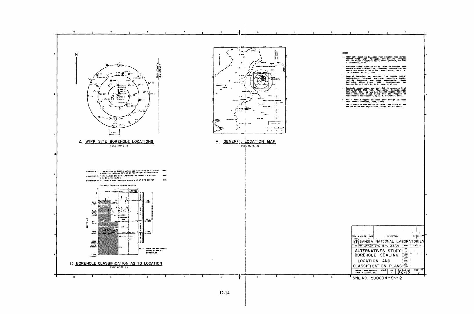
+ 1O__-.J ~__.L....__':"-__..L...-__"';""__..J...__~__ i_t-I __6__-.J1 , ..L._I__...:.·__--JI ·~__..L._I__..:.'__~
I
2. BorehOla Cl_UicaUon •• to Location section froas.urolA RI:POR'I' SAIIDIl-219~, -seal1nq conc.~ tor the•••te llaOlatlon pilot Plant (WIP') Sit.-, by c. L.e:tlrl.tanaen••t. _1.. 1982.
1. WIP' sit. Borehole Location plan aCSapted froa SAJlOIAREPORT s.\Jf1)14-1057. ·Pl\lCJ91ng and seaUnq Proqr_for tha ....tA laolaUon PUot Plant (NIPPl-. by JohnC. Sto~t, 198••
I-
-). General Locat.ion llap adopted trOll SAlfDlA RaPOItTSAllD89-oC62, ·Sy.t... Analyat., Lonqi-hra Radionuclide 't'ranapart and Dcaa .......-ne.. ttaat.IlIOlation .ilot Plant (N1P'). South...tarn ...."ldco. Karch 19"-, by A. R. lAppin, at aI.
e. Borehole c:oordina~ ara provlc1ed 1n AppIlndlx I ofSAMOlA RBPORT SAJn)-7U7. -Pralialnary Geohyc1rolQ91cConceptual JI04el of tbe 1..0- lledanoe Region ._r the....t. taolat.lon PUot Plant tor the P\l~ ofhrtol'anee ,........nt·. by It. P. BrinatAr, 1991.
5. tIPC - WI'P Pluqqlnq Criteria t... O-lqn crit.d.Requlr-.tt Docuaant, June, 1992).
SlIM - stat. of __ "'deo criteri_ (... Stat. of ....Mexico Rul.. and R-.;u.laUona, Ordar Ko. R-lll-A).
, I ...
MAP
., .1·---1
'-- ,T-.._- ,
.,__ I
'!:;? :~';- 1-.".'---' .~;
:, ......-t-.....
"'1GENERi ,I. LOCATION
iS1E NOTE 3)
8.
~ IA. WIPP SITE BOREHOLE LOCATIONS
(SEE NOTE I)
N
o
cCONDITION 1: 'T'Utlll'NATION IN SALADO WITHIN 30S ml1000 ttl OF MAX'IlIUIII WPC
POTENTIAL lATUUl EXTENT Of AI!,OSITOAY DEVElOPIIIlNT
CONDIT'ON 1: TlEllWINATtON IllOW $AlADOtCASTU.f INTf.RFACf WITH'N WPC2 MI Of SITI! CENTER
CONOITION ): ALL OTHER PENETRATIONS WITHIN 3 11I1 OF SITE C£NTfA INIlI
10
•
w.o.
..............P~OHS BRlfrtCl(ERHOf'F ISCALE: I SIZE I ~ OWG.~, I St€E T NO
QU'1l( " DOu<A&S. INC. 0 ~K- I" i Of
ALTERNATIVES STUDY ~~.BOREHOLE SEALING
LOCATION ANDCLASSIFICATION PLANS ::
II, ! i : ~
~ a .·,0 REY '~.T~ DESCIltIPTIOH IB'l'ICI(', APP
ffiSANOiA NATIONAL LABORATORIESW/PP CONCEPTUAL SEAL DESIGN
I SNL NO. 500004 - SK-12
I-
1,,"OT(: DOT I C-I IIIPRIIINT
TOTAL Dl!I'TN 0'IORINOLI.
DOE-CONTROLLED
'"
I......i •••'0' I ~ CISO)
(1000) II ::
'~.:' :·'1-- g z0
"0 f-::" t· .. N(2000) ~ "... :>12150) WI"" HORIZON I .. It
:: IcOHO'TIO"~ ~i I - I let •
Z ." ,.125'15(3000) ....
;:.. ....u
12t' 1242(4000) .. C407S)
'"..•1524 ~
(1000) "4&72
CtSOOO)
DlST ANeE FROM SITE CENTER IN WILES
•
4'77CtlOOO)
C. BOREHOLE CLASSIFICATION AS TO LOCATION(SEE NOTE 2)
D-14
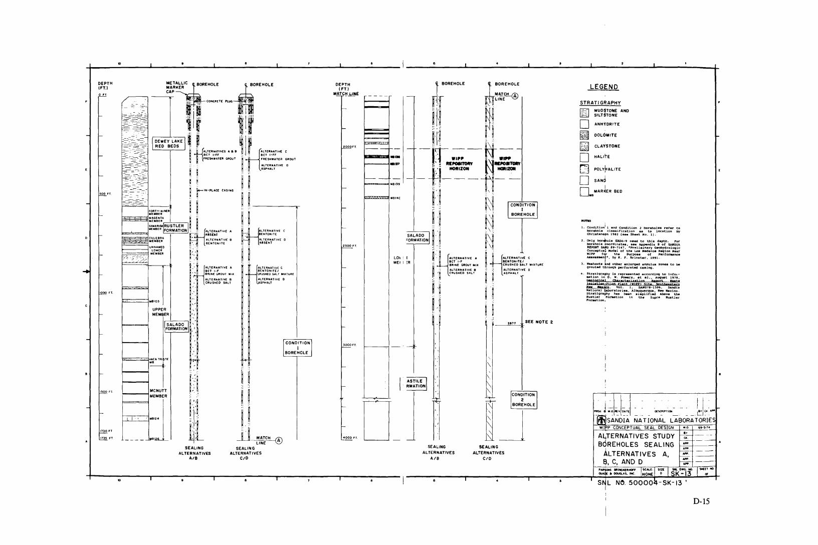
1. conditionl1 and Condition 2 boreholes refer to
borehole classific.tion •• to location byChristens,n 1982 (s.. Sheet No. 11.
2. OnIV bor",ole ERDA-9 CnH to this depth. Porborehole coordin.te., see App.ndix a at SMlDtAREPORT SAJro 89-7147, -Prelbin.ry ~ydroloqicConc.ptua~ Mod.l at tn_ Los Ned.no. Req10n ....rWIPP feu th. Purpo.e ot Pertor.-nc.Aaaea__nt-, by It. ,. Brin.t.r, 1991.
J. Washouts ind other .nlsrqed snnulus %on_ to beqrouted t.hrol)qb pertorated caalnq.
4. 9traUqraphy Is repr•••nted ac.;cordl09 to In(OI_t10n in D. W. Powera, .t al., Auquat 1971,
i:~:1:!pi1;:a:r;::'l:::Jfnsite8';~ ••:::~'ow 11I,111;;0, Vol. 1, 5.Uf071-1 !t96 , 5andl.N.t ional ~r.tories, Albuquerque, 11... Mas1co.Str.ti9ra~y has been aiapliUed at:cv. theRustl.r POr1l8tion 1n th. supra RustlerrOrallt i on.
• I 2 I,
LEGEND
STRATIGRAPHY •
~MUDSTONE AND
~.: SILTSTONE
0 ANHYDRITE
~ DoulMITE ~
~ CLAYSTONE
0 HALITE
(j POL+ALITE..£
0 SANd
Io MARKER BED118
~
IIO'nS
I
~BOREHOLE
"!ATCH ®LINE
W~ ~
III
-
I BOREHOLE
nrH~H~
- -tt W." -It- -t.~_·~,r,' "'..o.t~ l\l-.:::-r--Ti --tl--i~ ~ Ir-:--"::---'~-=-~~-~:""I
----'----,SALADOI ~ '.- ~" ~\~=ORMATIONI ~ ~ ~\~
~ -HALTERH"'VE A ~;' flO,ALTERH.. 'vE CBCT l-F BENTONITEI
~BRINE GROUT MIX CRUSHED SALT MIXTURE
;: ALTERNATIVE B :: ALTERNATIYE 0'~ COuSHEO SALT ~ ~ ASPHALT
~ ,~ H
H ::
LOIMEl
-----
----
~IIIIIIII~...!-----4.,P
2000FT.
2S00 FT
DEPTH(FT)
MATC!:lJ:l!lE
AL TE R,.AT IV( CBENTONITE ICRUS"fO SALT MIXTURE
ALTERNATIVE 0SPHALT
-= ::.,--=--=:-
UPPERMEMBER "
~:::::===j"BIO'
:=--':,:.:::--~-=-~~:=-=~-=---:-=~ ~- _..- -_.- --
METAltiLICBOREHOLE ~OREHOLEMARKERCAP
-------"
~i ~ '-'''' -mIr--~~~E~-'-i-----'~:EI~ ~ ~ _I ~
~,. t1:ALTERNATIVES" a 8 ~ H~ALTERNATIVE
BeT I~FF :;. :. BCT l-FF
FRESHWATER GROUT ij , 'RE$HWATER GROUT
:: :: ALTlRHATI'iE
~ ~ :, .. j: ASPHALT
~ H. ~ ~~ r 'H-PlACE CAS'HG
, . ~ ~FORTY·HIHER ~_ ~,. ~ ----y-MEMBER ~
~~~3§j::~~~~A ~ ~ ~ .TAMAR' RUSTLER I~ ~ ;' :
iiiii;M£MBER FORMATIONI:fH'ALTEA,.ATIVE ~LTER"'ATIVE C• ABS£MT • BENTONITE
~~~E8BE~A • • ALTERNATIVE 8 .. ALTERNATIVE" BENTONITE I ABSENT
F'::~ /::_-~ US;S;!: f~ ij ~
ALTERNATIVE ABCT I-F
'; ----'1 8R'Nf G"OUT MIX
, ALTERNATIVE BCRUSHEO SALT
10
1000 FT.
~oo Ff
DEPTH(FT.l
SALADO "FORMATION
21n
ISOO F'T
1100 FT
173S FT.
10
F=:::==Z'~:~A llU lE
-
~__.....,MCNUTTMEMBER
f---J"-'__---l,1 .,0124
3000F"T.,
-
1-1".- \
\'.
ij ~F~, \
ASTILE II \RMATION ,
~ ~\
, "
~j:::1.'
!i,! 0_~ . ~ ,
~L jJ MATCH ® 4000 FT. -LINE
SEALING SEALING SEALING SEALING
ALTERNATIVES ALTERNATIVES ALTERNATIVES ALTERNATIVESAlB CID AlB CID
II, • I
A3TERNATIVES STUDY8y -- ---r--CIt. ----
B REHOLES SEALING--- A-~ ----
ALTERNATIVES A, ~- ---t--- ._---
~, C, AND D -. ----~
PARS<:WS BRINCJ([RtICn II~AU: ISIll Iso.... NO. 19«~M)OUAO< • OClUCUS. INC. NONE 0 K - 13
• ISNL NO. 50000~-SK-13 '
D-15
PERFORMANCE ASSESSMENT DISTRIBUTION LIST(Send Distribution list changes to M.M. Gruebel, Dept. 6342, Sandia
National laboratories, PO Box 5800, Albuquerque, NM 87185-5800)
Federal Agencies
US Department of Energy (2)Office of Environmental Restoration
and Waste ManagementAttn: EM-1
C. Frank, EM-50Washington, DC 20585
US Department of Energy (3)Office of Environmental Restoration
and Waste ManagementAttn: M. Frei, EM-34 (Trevion II)Director, Waste Management ProjectsWashington, DC 20585-0002
US Department of EnergyOffice of Environmental Restoration
and Waste ManagementAttn: J. Lytle, EM-30 (Trevion II)Washington, DC 20585-0002
US Department of EnergyOffice of Environmental Restoration
and Waste ManagementAttn: S. Schneider, EM-342
(Trevion II)Washington, DC 20585-0002
US Department of Energy (3)WIPP Task ForceAttn: G.H. Daly
S. FucignaB. Bower
12800 Middlebrook Rd.Suite 400Germantown, MD 20874
US Department of Energy (4)Office of Environment, Safety and
HealthAttn: R.P. Berube, EH-20
C. Borgstrum, EH-25R. Pelletier, EH-231K. Taimi, EH-232
Washington, DC 20585
Dist-l
US Department of Energy (5)WIPP Project Integration OfficeAttn: W.J. Arthur III
R. BeckerP. DickmanL.W. GageP.J. HigginsD.A. Olona
PO Box 5400Albuquerque, NM 87115-5400
US Department of Energy (10)WIPP Project Site Office (Carlsbad)Attn: A. Hunt (4)
V. Daub (4)J. LippisK. Hunter
PO Box 3090Carlsbad, NM 88221-3090
US Department of Energy, (5)Office of Civilian Radioactive Waste
ManagementAttn: Deputy Director, RW-2
Associate Director, RW-lOOffice of ProgramAdministration andResources Management
Associate Director, RW-20Office of FacilitiesSiting and Development
Associate Director, RW-30Office of SystemsIntegration andRegulations
Associate Director, RW-40Office of ExternalRelations and Policy
Office of Geologic RepositoriesForresta1 BuildingWashington, DC 20585
US Department of EnergyAttn: National Atomic Museum LibraryAlbuquerque Operations OfficePO Box 5400Albuquerque, NM 87185
US Department of EnergyResearch & Waste Management DivisionAttn: DirectorPO Box EOak Ridge, TN 37831
US Department of Energy (2)Idaho Operations OfficeFuel Processing and Waste
Management Division785 DOE PlaceIdaho Falls, ID 83402
US Department of EnergySavannah River Operations OfficeDefense Waste Processing
Facility Project OfficeAttn: W.D. PearsonPO Box AAiken, SC 29802
US Department of Energy (2)Richland Operations OfficeNuclear Fuel Cycle & Production
DivisionAttn: R.E. Gerton825 Jadwin Ave.PO Box 500Richland, WA 99352
US Department of Energy (3)Nevada Operations OfficeAttn: J.R. Boland
D. LivingstonP.K. Fitzsimmons
2753 S. Highland DriveLas Vegas, NV 89183-8518
US Department of Energy (2)Technical Information CenterPO Box 62Oak Ridge, TN 37831
US Department of Energy (2)Chicago Operations OfficeAttn: J.C. Haugen9800 South Cass AvenueArgonne, IL 60439
US Department of EnergyLos Alamos Area Office528 35th StreetLos Alamos, NM 87544
US Department of Energy (3)Rocky Flats Area OfficeAttn: w.e. Rask
G. HuffmanT. Lukow
PO Box 928Golden, CO 80402-0928
US Department of EnergyDayton Area OfficeAttn: R. GrandfieldPO Box 66Miamisburg, OH 45343-0066
US Department of EnergyAttn: E. YoungRoom E-178GAO/RCED/GTNWashington, DC 20545
US Bureau of Land Management101 E. MermodCarlsbad, NM 88220
US Bureau of Land ManagementNew Mexico State OfficePO Box 1449Santa Fe, NM 87507
US Environmental ProtectionAgency (2)
Office of Radiation ProtectionPrograms
ANR-460Washington, DC 20460
US Nuclear Regulatory CommissionDivision of Waste ManagementAttn: H. MarsonMail Stop 4-H-3Washington, DC 20555
US Nuclear Regulatory Commission (4)Advisory Committee on Nuclear WasteAttn: D. Moeller
M.J. SteindlerP.W. PomeroyW.J. Hinze
7920 Norfolk Ave.Bethesda, MD 20814
Dist-2
Defense Nuclear Facilities SafetyBoard
Attn: D. Winters625 Indiana Ave. NWSuite 700Washington, DC 20004
Nuclear Waste Technical ReviewBoard (2)
Attn: Library1100 Wilson Blvd., Suite 910Arlington, VA 22209-2297
Energy and Science DivisionOffice of Management and BudgetAttn: K. Yuracko725 17th Street NWWashington, DC 20503
US Geological Survey (2)Water Resources DivisionAttn: C. Peters4501 Indian School NESuite 200Albuquerque, NM 87110
State Agencies
New Mexico Bureau of Minesand Mineral Resources
Socorro, NM 87801
New Mexico Energy, Minerals andNatural Resources Department
Attn: Librarian2040 South PachecoSanta Fe, NM 87505
New Mexico Energy, Minerals andNatural Resources Department
New Mexico Radioactive Task Force (2)(Governor's WIPP Task Force)Attn: A. Lockwood, Chairman
C. Wentz, Policy Analyst2040 South PachecoSanta Fe, NM 87505
Bob ForrestMayor, City of CarlsbadPO Box 1569Carlsbad, NM 88221
Dist-3
Executive DirectorCarlsbad Department of DevelopmentAttn: C. BernardPO Box 1090Carlsbad, NM 88221
New Mexico Environment DepartmentSecretary of the Environment (3)Attn: J. EspinosaPO Box 9681190 St. Francis DriveSanta Fe, NM 87503-0968
New Mexico Environment DepartmentAttn: P. McCaslandWIPP Project Site OfficePO Box 3090Carlsbad, NM 88221-3090
New Mexico State Engineer's OfficeAttn: M. ChudnoffPO Box 25102Santa Fe, NM 87504-5102
Environmental Evaluation Group (5)Attn: R. Neill7007 Wyoming Blvd. NESuite F-2Albuquerque, NM 87109
Advisory Committee on NuclearFacility Safety
John F. AhearneExecutive Director, Sigma Xi99 Alexander DriveResearch Triangle Park, NC 27709
James E. Martin109 Observatory RoadAnn Arbor, MI 48109
WIPP Panel of National Research Council'sBoard on Radioactive Waste Management
Charles Fairhurst, ChairmanDepartment of Civil and
Mineral EngineeringUniversity of Minnesota500 Pillsbury Dr. SEMinneapolis, MN 55455-0220
John O. Blomeke3833 Sandy Shore DriveLenoir City, TN 37771-9803
John D. BredehoeftWestern Region HydrologistWater Resources DivisionUS Geological Survey (MIS 439)345 Middlefield RoadMenlo Park, CA 94025
Fred M. Ernsberger1325 NY 10th AvenueGainsville, FL 32601
Rodney C. EwingDepartment of GeologyUniversity of New Mexico200 Yale NEAlbuquerque, NM 87131
B. John GarrickPLG, Inc.Suite 4004590 MacArthur Blvd.Newport Beach, CA 92660-2027
Leonard F. KonikowUS Geological Survey431 National CenterReston, VA 22092
Jeremiah O'Driscoll505 Valley Hill DriveAtlanta, GA 30350
Christopher WhippleClement International Corp.160 Spear St.Suite 1380San Francisco, CA 94105-1535
National Research Council (3)Board on Radioactive
Waste ManagementRM HA456Attn: P.B. Myers (2)
G.J. Grube2101 Constitution Ave.Washington, DC 20418
Dist-4
Performance Assessment Peer Review Panel
G. Ross HeathCollege of Ocean and
Fishery Sciences, HN-15583 Henderson HallUniversity of WashingtonSeattle, WA 98195
Thomas H. PigfordDepartment of Nuclear Engineering4159 Etcheverry HallUniversity of CaliforniaBerkeley, CA 94720
Thomas A. CottonJK Research Associates, Inc.4429 Butterworth Place NWWashington, DC 20016
Robert J. BudnitzPresident, Future Resources
Associates, Inc.2000 Center StreetSuite 418Berkeley, CA 94704
C. John MannDepartment of Geology245 Natural History Bldg.1301 West Green StreetUniversity of IllinoisUrbana, IL 61801
Frank W. SchwartzDepartment of Geology and MineralogyThe Ohio State UniversityScott Hall1090 Carmack Rd.Columbus, OH 43210
National Laboratories
Argonne National Laboratory (2)Attn: A. Smith
D. Tomasko9700 South CassBldg. 201Argonne, IL 60439
Savannah River Plant (2)Attn: R.G. Baxter
Bldg. 704-SK.W. Wierzbicki
Bldg. 703-HAiken, SC 29808-0001
MSIN P8-44
Battelle Pacific Northwest Laboratory(3)
Attn: R.E. Westerman,S. Bates
Battelle BoulevardRichland, WA 99352
83403-4000
Westinghouse-Savannah River TechnologyCenter (4)
Attn: N. BiblerJ.R. HarbourM.J. PlodinecG.G. Wicks
Aiken, SC 29802
Corporations/Members of the Public
City of AlbuquerquePublic Works DepartmentUtility Planning DivisionAttn: W.K. SummersPO Box 1293Albuquerque, NM 87103
Deuel and Associates, Inc.Attn: R.W. Prindle7208 Jefferson NEAlbuquerque, NM 87109
Benchmark Environmental Corp.Attn: C. Frederickson4501 Indian School NESuite 105Albuquerque, NM 87110
Disposal Safety, Inc.Attn: B. Ross1660 L Street NWSuite 314Washington, DC 20036
Los Alamos National LaboratoryAttn: A. MeijerPO Box 1663Mail Stop J5l4Los Alamos, NM 87545
H. LooR. Klinger
Mail Stop 5108Idaho Falls, ID
Idaho National Engineering Laboratory(2)
Attn:
Los Alamos National LaboratoryAttn: B. Erdal, CNC-llPO Box 1663Los Alamos, NM 87545
Los Alamos National LaboratoryEM-7
Attn: S. KosiewiczPO Box 1663Mail Stop J595Los Alamos, NM 87545
Los Alamos National Laboratory (3)HSE-8
Attn: M. EnorisL. SoholtJ. Wenzel
PO Box 1663Los Alamos, NM 87545
Oak Ridge National LaboratoryTransuranic Waste ManagerAttn: D.W. TurnerPO Box 2008Bldg. 3047Oak Ridge, TN 37831-6060
Ecodynamics (2)Attn: P. Roache
R. BlainePO Box 9229Albuquerque, NM 87119-9229
Pacific Northwest LaboratoryAttn: B. KennedyPO Box 999Richland, WA 99352
EG & G Idaho (3)1955 Fremont StreetAttn: C. Atwood
C. HertzlerT.I. Clements
Idaho Falls, ID 83415
Dist-5
GeomatrixAttn: K. Coppersmith100 Pine Street, Suite 1000San Francisco, CA 94111
Golder Associates, Inc. (3)Attn: M. Cunnane
R. Kqssik1. Miller
4104 l48th Avenue NERedmond, YA 98052
INTERA, Inc.Attn: A.M. LaVenue1650 University Blvd. NESuite 300Albuquerque, NM 87102
INTERA, Inc.Attn: J.F. Pickens6850 Austin Center Blvd.Suite 300Austin, TX 78731
INTERA, Inc.Attn: Y. StensrudPO Box 2123Carlsbad, NM 88221
INTERA, Inc.Attn: Y. Nelson101 Convention Center DriveSuite 540Las Vegas, NV 89109
IT Corporation (2)Attn: R.F. McKinney
J. MyersRegional Office, Suite 7005301 Central Avenue NEAlbuquerque, NM 87108
John Hart and Associates, P.A.Attn: J.S. Hart2815 Candelaria Road NYAlbuquerque, NM 87107
John Hart and Associates, P.A.Attn: K. Lickliter1009 North YashingtonTacoma, YA 98406
Dist-6
MACTEC (1)Attn: O.K. Duncan8418 Zuni Road SESuite 200Albuquerque, NM 87108
Newman and HoltzingerAttn: C. Mallon1615 L Street NYSuite 1000Washington, DC 20036
Parsons Brinckerhoff Quade andDouglas, Inc.
Attn: M.S. Lin (2)C.D. MannD.O. Luo
303 Second StreetSuite 700 NorthSan Francisco, CA 94107-1317
RE/SPEC, Inc. (2)Attn: Y. Coons4775 Indian School NESuite 300Albuquerque, NM 87110
RE/SPEC, Inc.Attn: J.L. RatiganPO Box 725Rapid City, SO 57709
RE/SPEC, Inc.Attn: L.L. Van Sambeek (2)PO Box 725Rapid City, SO 57709
Reynolds Elect/Engr. Co., Inc.Attn: E.Y. KendallBuilding 790Warehouse RowPO Box 98521Las Vegas, NV 89193-8521
Science Applications InternationalCorporation (SAIC)
Attn: H.R. Pratt10260 Campus Point DriveSan Diego, CA 92121
Science Applications InternationalCorporation (2)
Attn: D.C.RoyerC.G. Pflum
101 Convention Center Dr.Las Vegas, NV 89109
Science Applications InternationalCorporation (2)
Attn: M. DavisJ. Tollison
2109 Air Park Road SEAlbuquerque, NM 87106
Science Applications InternationalCorporation (2)
Attn: J. YoungD. Lester
18706 North Creek Parkway, Suite 110Bothell, WA 98011
Southwest Research InstituteCenter for Nuclear Waste Regulatory
Analysis (2)Attn: P.K. Nair6220 Cu1ebra RoadSan Antonio, TX 78228-0510
Systems, Science, and Software (2)
Attn: E. PetersonP. Lagus
Box 1620La Jolla, CA 92038
TASCAttn: S.G. Oston55 Walkers Brook DriveReading, MA 01867
Tech Reps, Inc. (7)Attn: J. Chapman
C. CrawfordV. GillilandD. MarchandJ. StikarP. OliverD. Scott
5000 Marble NE, Suite 222Albuquerque, NM 87110
Dist-7
Tolan, Beeson & AssociatesAttn: T.L. Tolan2320 W. 15th AvenueKennewick, WA 99337
TRW Environmental Safety Systems (2)Attn: I. Sacks, Suite 800
L. Wildman, Suite 13002650 Park Tower DriveVienna, VA 22180-7306
Westinghouse Electric Corporation (4)Attn: Library
C. CoxL. FitchR.F. Kehrman
PO Box 2078Carlsbad, NM 88221
Westinghouse Hanford CompanyAttn: D.E. WoodMSIN HO-32PO Box 1970Richland, WA 99352
Western Water ConsultantsAttn: D. Fritz1949 Sugarland Drive #134Sheridan, WY 82801-5720
Western Water ConsultantsAttn: P.A. RechardPO Box 4128Laramie, WY 82071
P. Drez8816 Cherry Hills Road NEAlbuquerque, NM 87111
D.W. PowersStar Route Box 87Anthony, TX 79821
Shirley ThiedaPO Box 2109, RR1Bernalillo, NM 87004
Jack Urichc/o CARD144 Harvard SEAlbuquerque, NM 87106
Universities
University of CaliforniaMechanical, Aerospace, and
Nuclear Engineering Department (2)Attn: W. Kastenberg
D. Browne5532 Boelter HallLos Angeles, CA 90024
University of CaliforniaMine Engineering Dept.Attn: N. CookRock Mechanics EngineeringBerkeley, CA 94720
University of Hawaii at HiloAttn: S. HoraBusiness AdministrationHilo, HI 96720-4091
University of New MexicoGeology DepartmentAttn: LibraryAlbuquerque, NM 87131
University of New MexicoResearch AdministrationAttn: H. Schreyer102 Scholes HallAlbuquerque, NM 87131
University of WyomingDepartment of Civil EngineeringAttn: V.R. HasfurtherLaramie, WY 82071
University of WyomingDepartment of GeologyAttn: J.I. DreverLaramie, WY 82071
University of WyomingDepartment of MathematicsAttn: R.E. EwingLaramie, WY 82071
Ubraries
Thomas Brannigan LibraryAttn: D. Dresp106 W. Hadley St.Las Cruces, NM 88001
Dist-8
Hobbs Public LibraryAttn: M. Lewis509 N. Ship StreetHobbs, NM 88248
New Mexico State LibraryAttn: N. McCallan325 Don GasparSanta Fe, NM 87503
New Mexico TechMartin Speere Memorial LibraryCampus StreetSocorro, NM 87810
New Mexico Junior CollegePannell LibraryAttn: R. HillLovington HighwayHobbs, NM 88240
Carlsbad Municipal LibraryWIPP Public Reading RoomAttn: L. Hubbard101 S. Halagueno St.Carlsbad, NM 88220
University of New MexicoGeneral LibraryGovernment Publications DepartmentAlbuquerque, NM 87131
NEA/Performance Assessment AdvisoryGroup (PAAG)
P. DuerdenANSTOLucas Heights Research LaboratoriesPrivate Mail Bag No. 1Menai, NSW 2234AUSTRALIA
Gordon S. LinsleyDivision of Nuclear Fuel Cycle and
Waste ManagementInternational Atomic Energy AgencyPO Box 100A-1400 Vienna, AUSTRIA
Nicolo CadelliCommission of the European Communities200, Rue de la LoiB-l049 Brussels, BELGIUM

R. HeremansOrganisme Nationale des Dechets
Radioactifs et des MatieresFissi1es
ONDRAFPlace Madou 1, Boitec 24/25B-l030 Brussels, BELGIUM
J. MarivoetCentre d'Etudes de l'Energie NucleaireCEN/SCKBoeretang 200B-2400 Mol, BELGIUM
P. ConlonWaste Management DivisionAtomic Energy Control Board (AECB)PO Box 1046Ottawa, Canada KIP 559, CANADA
A.G. WikjordManager, Environmental and Safety
Assessment BranchAtomic Energy of Canada LimitedWhiteshell Nuclear Research
EstablishmentPinewa, Manitoba ROE lLOCANADA
Jukka-Pekka Sa10Teollisuuden Voima Oy (TVO)Fredrikinkatu 51-53 BSF-OOlOO HelsinkiFINLAND
Timo VienoTechnical Research Centre of Finland
(VTT)Nuclear Energy LaboratoryPO Box 208SF-02l5l Espoo, FINLAND
Timo AiltiisTeol1isuuden Voima Oy (TVO)Fredrikinkatu 51-53 BSF-OOlOO Helsinki, FINLAND
Dist-9
M. Claude RingeardDivision de la Securite et de la
Protection de l'Environment (DSPE)Commissariat a l'Energie AtomiqueAgence Nationale pour la Gestion des
Dechets Radioactifs (ANDRA)Route du Panorama Robert SchumanB. P. No. 38F-92266 Fontenay-aux-Roses CedexFRANCE
Gerald OuzounianAgence Nationale pour la Gestion des
Dechets Radioactifs (ANDRA)Route du Panorama Robert SchumanB.P. No. 38F-92266 Fontenay-aux-Roses CedexFRANCE
Claudio PescatoreDivision of Radiation Protection and
Waste ManagementOECD Nuclear Energy Agency38, Boulevard SuchetF-750l6 Paris, FRANCE
M. Dominique GrenecheCommissariat a l'Energie AtomiqueIPSN/DAS/SASICC/SAEDB.P. No.6F-92265 Fontenay-aux-Roses CedexFRANCE
Robert FabriolBureau de Recherches Geologiques et
Minieres (BRGM)B.P. 600945060 Orleans Cedex 2, FRANCE
P. BogorinskiGesellschaft fur Reaktorsicherheit
(GRS) mbHSchwertnergasse 1D-5000 K6ln 1, GERMANY
R. StorckGSF - Institut fur TieflagerungTheodor-Heuss-Strabe 4D-3300 Braunschweig, GERMANY

Ferrucio GeraISMES S.p.AVia del Crociferi 441-00187 Rome, ITALY
Hiroyuki UmekiIsolation System Research ProgramRadioactive Waste Management ProjectPower Reactor and Nuclear Fuel
Development Corporation (PNC)1-9-13, AkasakaMinato-kuTokyo 107, JAPAN
P. Carboneras MartinezENRESACalle Emilio Vargas, 7R-28043 Madrid, SPAIN
Tanis PappSwedish Nuclear Fuel and Waste
Management Co.Box 5864S 102 48 Stockholm, SWEDEN
Conny HAggSwedish Radiation Protection Institute
(SSI)Box 60204S-104 01 Stockholm, SWEDEN
J. HadermannPaul Scherrer InstituteWaste Management ProgrammeCH-5232 Villigen PSI, SWITZERLAND
J. VigfussonUSK- Swiss Nuclear Safety InspectorateFederal Office of EnergyCH-5303 Wurenlingen, SWITZERLAND
D.E. BillingtonDepartmental Manager-Assessment
StudiesRadwaste Disposal R&D DivisionAEA Decommissioning & RadwasteHarwell Laboratory, B60Didcot Oxfordshire OXII ORAUNITED KINGDOM
Dist-10
P. GrimwoodWaste Management UnitBNFLSellafieldSeasca1e, Cumbria CA20 lPGUNITED KINGDOM
Alan J. HooperUK Nirex LtdCurie AvenueHarwell, DidcotOxfordshire, OXII ORHUNITED KINGDOM
Jerry M. BoakYucca Mountain Project OfficeUS Department of EnergyPO Box 98608Las Vegas, NV 89193
Seth M. Coplan (Chairman)US Nuclear Regulatory CommissionDivision of High-Level Waste
ManagementMail Stop 4-H-3Washington, DC 20555
A.E. Van LuikINTERA/M&OThe Valley Bank Center101 Convention Center Dr.Las Vegas, NV 89109
NEA/PSAG User's Group
Shaheed HossainDivision of Nuclear Fuel Cycle and
Waste ManagementInternational Atomic Energy AgencyWagramerstrasse 5PO Box 100A-l400 Vienna, AUSTRIA
Alexander Nies (PSAC Chairman)Gesellschaft fur Strahlen- undInstitut fur TieflagerungAbteilung fur EndlagersicherheitTheodor-Heuss-Strasse 4D-3300 Braunschweig, GERMANY
Eduard HoferGesellschaft fur Reaktorsicherheit
(GRS) MBHForschungsgelAndeD-8046 Garching, GERMANY
Andrea SaltelliCommission of the European CommunitiesJoint Resarch Centre of Ispra1-21020 Ispra (Varese) , ITALY
Alejandro AlonsoCatedra de Tecnologia NuclearE.T.S. de Ingenieros IndustrialesJose Gutierrez Abascal, 2E-28006 Madrid, SPAIN
ENRESA (2)Attn: M. A. Cunado
F. J. ElorzaCalle Emilio Vargas, 7E-28043 Madrid, SPAIN
Pedro PradoCIEMATInstituto de Tecnologia NuclearAvenida Complutense, 22E-28040 Madrid, SPAIN
Nils A. KjellbertSwedish Nuclear Fuel and Waste
Management Company (SKB)Box 5864S-102 48 Stockholm, SWEDEN
Bjorn CronhjortSwedish National Board for Spent
Nuclear Fuel (SKN)Sehlsedtsgatan 95-115 28 Stockholm, SWEDEN
Richard A. KlosPaul-Scherrer Institute (PSI)CH-5232 Villingen PSISWITZERLAND
NAGRA (2)Attn: C. McCombie
F. Van DorpHardstrasse 73CH-5430 Wettingen, SWITZERLAND
Dist-ll
N. A. ChapmanIntera Information TechnologiesPark View House, l4B Burton StreetMelton MowbrayLeicestershire, LE13 lAEUNITED KINGDOM
Daniel A. GalsonGalson Sciences Ltd.35, Market PlaceOakhamLeicestershire LEIS 6DTUNITED KINGDOM
David P. HodgkinsonIntera Information TechnologiesChiltern House45 Station RoadHenley-on-ThamesOxfordshire RG9 lAT, UNITED KINGDOM
Brian G.J. ThompsonDepartment of the Environment: HerMajesty's Inspectorate of PollutionRoom A5.33, Romney House43 Marsham StreetLondon SWlP 2PY, UNITED KINGDOM
Intera Information TechnologiesAttn: M.J.Apted3609 South Wadsworth Blvd.Denver, CO 80235
US Nuclear Regulatory Commission (2)Attn: R. Codell
N. EisenbergMail Stop 4-H-3Washington, DC 20555
Battelle Pacific NorthwestLaboratories
Attn: P.W. EslingerPO Box 999, MS K2-32Richland, WA 99352
Center for Nuclear Waste RegulatoryAnalysis (CNWRA)
Southwest Research InstituteAttn: B. SagarPO Drawer 285106220 Culebra RoadSan Antonio, TX 78284

Geostatistics Expert Working Group (GXG)
Rafael L. BrasR.L. Bras Consulting Engineers44 Percy RoadLexington, MA 02173
Jesus CarreraUniversidad Polit~cnica de CatalunaE.T.S.I. CaminosJordi, Girona 31E-08034 Barcelona, SPAIN
Alan GutjahrDepartment of MathematicsNew Mexico Institute of Mining and
TechnologySocorro, NM 87801
C. Peter JacksonHarwell LaboratoryTheoretical Studies DepartmentRadwaste Disposal DivisionBldg. 424.4Oxfordshire Didcot Oxon OXII ORAUNITED KINDGOM
Peter Kitanidis60 Peter Coutts CircleStanford, CA 94305
Civil EngineeringInstitute of Technology
02139
Civil EngineeringCalifornia94720
Dennis McLaughlinParsons LaboratoryRoom 48-209Department ofMassachusettsCambridge, MA
Rae MackayDepartment of Civil EngineeringUniversity of Newcastle Upon TyneNewcastle Upon Tyne NEl 7RUUNITED KINGDOM
Shlomo P. NeumanCollege of Engineering and MinesDepartment of Hydrology and Water
ResourcesUniversity of ArizonaTucson, AZ 85721
Yoram RubinDepartment ofUniversity ofBerkeley, CA
Christian RavenneGeology and Geochemistry DivisionInstitut Francais du Petrole1 & 4, Av. de Bois-Preau BP31l92506 Rueil Malmaison CedexFRANCE
Alain GalliCentre de GeostatistiqueEcole des Mines de Paris35 Rue St. Honore77035 Fontainebleau, FRANCE
Steve GorelickDepartment of Applied Earth SciencesStanford UniversityStanford, CA 94305-2225
Ghislain de Marsily (GXG Chairman)University Pierre et Marie CurieLaboratorie de Geologie Applique4, Place Jussieu - T.26 - 5e etage75252 Paris Cedex 05FRANCE
Gedeon DaganDepartment of Fluid Mechanics and Heat
TransferTel Aviv UniversityPO Box 39040Ramat Aviv, Tel Aviv 69978ISRAEL
Peter GrindrodINTERA Information Technologies Ltd.Chiltern House45 Station RoadHenley-an-ThamesOxfordshire, RG9 lATUNITED KINGDOM
Dist-l2

Foreign Addresses
Studiecentrum Voor KernenergieCentre D'Energie NucleaireAttn: A. BonneSCK/CENBoeretang 200B-2400 Mol, BELGIUM
Atomic Energy of Canada, Ltd. (3)Whiteshell Research Estab.Attn: M.E. Stevens
B.W. GoodwinD. Wushke
Pinewa, ManitobaROE lLO, CANADA
Esko PeltonenIndustrial Power Company Ltd.TVOFredrikinkatu 51-53SF-00100 Helsinki 10, FINLAND
Jean-Pierre OlivierOECD Nuclear Energy Agency (2)38, Boulevard SuchetF-750l6 Paris, FRANCE
D. Alexandre, Deputy DirectorANDRA31 Rue de la Federation75015 Paris, FRANCE
Claude SombretCentre D'Etudes Nucleaires
De La Vallee RhoneCEN/VALRHOS.D.H.A. BP 17130205 Bagno1s-Sur-Ceze, FRANCE
Bundesministerium fur Forschung undTechno1ogie
Postfach 200 7065300 Bonn 2, GERMANY
Bundesanstalt fur Geowissenschaftenund Rohstoffe
Attn: M. LangerPostfach 510 1533000 Hanover 51, GERMANY
Dist-13
Gesellschaft fur Reaktorsicherheit(GRS) (2)
Attn: B. BaltesW. Muller
Schwertnergasse 1D-5000 Cologne, GERMANY
Institut fur Tieflagerung (2)Attn: K. KuhnTheodor-Heuss-Strasse 40-3300 Braunschweig, GERMANY
Physikalisch-TechnischeBundesansta1t
Attn: P. BrennekePostfach 33 45D-3300 Braunschweig, GERMANY
Shingo TashiroJapan Atomic Energy Research
InstituteTokai-Mura, Ibaraki-Ken319-11, JAPAN
Netherlands Energy ResearchFoundation (ECN)
Attn: L.H. Vons3 WesterduinwegPO Box 11755 ZG Petten, THE NETHERLANDS
Johan AnderssonSwedish Nuclear Power InspectorateStatens Karnkraftinspektion (SKI)Box 27106S-102 52 Stockholm, SWEDEN
Fred KarlssonSvensk Karnbransleforsorjning
AB SKBBox 5864S-102 48 Stockholm, SWEDEN
Nationa1e Genossenschaft fur dieLagerung Radioaktiver Abfa11e(NAGRA) (2)
Attn: S. VomvorisP. Zuidema
Hardstrasse 73CH-5430 Wettingen, SWITZERLAND
AEA TechnologyAttn: J.H. ReesD5W/29 Culham LaboratoryAbingtonOxfordshire OX14 3DB, UNITED KINGDOM
AEA TechnologyAttn: W.R. Rodwell044/A31 Winfrith Technical CentreDorchesterDorset DT2 8DH, UNITED KINGDOM
AEA TechnologyAttn: J.E. TinsonB4244 Harwell LaboratoryDidcot, Oxfordshire OX11 ORAUNITED KINGDOM
D.R. KnowlesBritish Nuclear Fuels, p1cRisley, WarringtonCheshire WA3 6AS. 1002607UNITED KINGDOM
Internal
63436345634563476348635163526352640066136613661366226641714171517613 -2
8523-2930093109330
Staff (3)R.C. LincolnStaff (9)D.R. SchaferJ.T. HolmesR.E. ThompsonD.P. GarberS.E. SharptonN.R. OrtizR.M. CranwellR.L. ImanC. LeighM.S.Y. ChuR.E. Luna, ActingTechnical Library (5)Technical PublicationsDocument Processing for
DOE/OSTI (10)Central Technical FilesJ.E. PowellJ.D. PlimptonJ.D. Kennedy
120150215116000610061156119611961216121612162336300630263036303630563066312631363316341634263426343
A. NarathO.E. JonesJ.C. CwnmingsO.K. GartlingD.L. HartleyR.W. LynchP.B. DaviesE.D. GorhamStaff (14)J.R. TillersonF.D. HansenStaff (7)J.C. EichelbergerD.E. EllisL.E. ShephardS.Y. PickeringW.O. WeartS.A. GoldsteinA.L. StevensF.W. BinghamL.S. CostinP.A. DavisSandia WIPP Central Files (100)D.R. AndersonStaff (30)S.A. Orrell, Acting
Dist-14
•
•
•
•~ u.s. GOVERNMENT PRINTING OFFICE 1992-775-122180189
•