sandip tiwari [email protected]/files/nanoelectronics_tiwari_short... ·...
TRANSCRIPT

Short Course, SouthKorea, 2006
Sandip Tiwari [email protected]
A discussion of electronics and some of its devices and circuits with emphasis on nanoscale effects in the context of applications and systems
Devices and Circuits of the Nanoscale
Background on electronics and CMOS devicesNanoscale in Silicon
Nanoscale in Other MaterialsNanoscale Devices
Circuits in the Context of Systems
Sandip Tiwari; Cornell University 2Short Course, SouthKorea, 2006
Electronics
Foundation of a trillion dollar information industry: smaller area, faster & cheaper year after year: Moore’s LawLemma: An industry that works hard and spends billions at putting itself out of business
Moore's Law - Transistors per Chip
Intel μP1
109
1950 1960 1970 1980 1990 2000 2010
Avg. increaseof 57%/year
4004
8086286
386486DX Pentium
P2
P3P4
Itanium 2Madison
108
107
106
105
104
103
102
10
Source: Intel

Sandip Tiwari; Cornell University 3Short Course, SouthKorea, 2006
Electronics
10-10 10-9 10-8 10-7 10-6 10-5 10-4 10-3 10-2 10-1 1 101 102 103
100
10-3
10-6
10-9
10-12
10-15
PhysicalBehavioralStructural
QuantumMaster Eq.NEG
DeviceBoltzmannHydrodynamicDrift-DiffusionMonte CarloAtomistic
CompactASX, Spice, …
LumpedInterconnect
Noise
Chip Floor Planning
PlacementTiming
CongestionRouting
VerificationTemperature
PowerElectromagnetic
ContinuumHigh Abstraction (HDL)
Length Scale (m)
Tim
e S
cale
(s)
Sandip Tiwari; Cornell University 4Short Course, SouthKorea, 2006
Elements of an Electronic System
LogicLogic execution, Logic interfacing (drivers, bus, interface, …)
MemoryCache, Data, Code, Storage, …(dynamic and non-volatile, … fast and slow)
CommunicationOn and off chip to other chips, boards, …
InterfacesDisplay, touch, sound, keyboard, sensors, other input/output
Hierarchical system design

Sandip Tiwari; Cornell University 5Short Course, SouthKorea, 2006
Bulk Transistor
We want:High on current Ion
Low off current Ioff
Rapid control between the two states
ideal is 0 mVpractical is 60+ mV for a decade change in current
ReproducibleLow sensitivity to variationsLow energy
Source: Skotnicki et al. (2005)
Sandip Tiwari; Cornell University 6Short Course, SouthKorea, 2006
Electron Transport in FETG
ateS
ourceD
rain
SiliconSubstrate
Credit

Sandip Tiwari; Cornell University 7Short Course, SouthKorea, 2006
Transistor
Log Lg (nm)
VGS (V)
VDS (V)
I D(A
)Lo
g I D
(A)
VT
(V)
I D(A
)
Charge confinement (doping)Mobility and effective velocity
ResistancesDoping and conductivity
Mobility
Charge confinementGate control
Charge confinement (doping and body)Gate control
Photo Credit
Sandip Tiwari; Cornell University 8Short Course, SouthKorea, 2006
Nanoscale
Scaling doesn’t quite work below 100+ nmIBM T. Kuroda

Sandip Tiwari; Cornell University 9Short Course, SouthKorea, 2006
Power
Source: B. Yu
Passive power increasing at rapid rate due to gate and inter-junction leakage
Dielectrics and junctions with increasing tunneling
Source: IBM
Sandip Tiwari; Cornell University 10Short Course, SouthKorea, 2006
Interconnects: 2D
Technology scaling occurs with increasing average interconnect length and routing density and increased interconnect aspect ratio
Interconnects grow linearly with cells in ordered arrays (memories, e.g.)Interconnects grow as the square of the elements in random logic
Local (intra-block) wires scale with block size, but global (inter-block) wires do not. Global wiring and increasing buffers become an increasingly problem
Wire Length (unit of die-size)
Pro
babi
lity
0.5
Local
Global
Fringing & Coupling
Capacitances

Sandip Tiwari; Cornell University 11Short Course, SouthKorea, 2006
Throughput & Power Dissipation in Buffers
Use of repeaters means more power, and absence means increased delays with global delays more dominantIn 65 nm high speed designs, the # of buffers is ~850K
More area, power and congestion
Source: Deodhar et al.180 nm technology
Driver Receiver
Sandip Tiwari; Cornell University 12Short Course, SouthKorea, 2006
Application Dependent Limits
Source: D. Frank et al. IEDM (1998)

Sandip Tiwari; Cornell University 13Short Course, SouthKorea, 2006
Power Dissipation in Small Dimensions & Temperature
105 W/cm2 => 100 C with package at 50 C at 0.18 m dimensionArea in which this dissipation occurs critical to temperature
103 104 10550
60
70
80
90
100
110
120
130 3D: 5 m SOI: 200nm BOX 3D: 1 m under driver
and 5 m elsewhere Bulk CMOS
Tem
pera
ture
(o C)
Power density (W/cm2)
10050
60
70
80
90
100
110
120
130
140
150
160
50 500
Tem
pera
ture
(o C)
Driver pitch ( m)
Liu et al., IEEE EDL (2002)
Sandip Tiwari; Cornell University 14Short Course, SouthKorea, 2006
Energy determines density for electronic nanosystems

Sandip Tiwari; Cornell University 15Short Course, SouthKorea, 2006
Consequences of Improving Electrostatics
Higher body doping Lower carrier mobilityHigher junction capacitanceHigher junction leakage
Thinner gate dielectric Higher leakage
Shallower junctions Higher resistance
So, there are always compromises to be made
Sandip Tiwari; Cornell University 16Short Course, SouthKorea, 2006
Statics and Dynamics
ElectrostaticsGate Control
Gate dielectrics, work-functions, …Substrates
Sharp halo’s and improved junctionsThin silicon bodies
ThresholdWork functions, doping, new geometries
ElectrodynamicsTransport
Strained materials (Si, SiGe, …), new orientations, new materials (Nanotubes, Ge, III-V, …)
ParasiticsNew contact materials, raised source-drain structures, etc.

Sandip Tiwari; Cornell University 17Short Course, SouthKorea, 2006
Non-Classical CMOS (Single Gate)
Transport enhancement Substrate Enhancement:Thin Body
Source/Drain Enhancement
Strained Si, Ge, SiGe, SiCGe, …on bulk Si & SOI
Fully depleted SOI with sub-10 nm body or ultra-thin channel and buried oxide
Low barrier Schottkysource/drain or non-overlappedextensions
Source: ITRS
Sandip Tiwari; Cornell University 18Short Course, SouthKorea, 2006
Non-Classical CMOS (Multi-Gate)
Source: ITRS
Tied Gates
Channels on multiple surfaces
Channels on side-walls
Channels on planar surfaces
Vertical transistor
Independent gatessource drain
gate

Sandip Tiwari; Cornell University 19Short Course, SouthKorea, 2006
Planar Transistors
Scaling limited
Enhanced by Si/SiGechannels
Scaling limited
But improved performancethat can be enhanced by bulk-likeapproaches
Enhancedscaling limits if thin silicon and low parasiticsfeasible
Enhancedscaling limits if thin silicon, two gates and low parasiticsfeasible
Bulk Silicon on Insulators: Various Forms
Sandip Tiwari; Cornell University 20Short Course, SouthKorea, 2006
Strain by Orientation
Yang et al. (2003)

Sandip Tiwari; Cornell University 21Short Course, SouthKorea, 2006
Transport Improvement by Orientations
Bond (110) onto (100) Si – oxide basedUse epitaxy of 100 with oxide isolation for (110)
Yang et al. (IBM)
Sandip Tiwari; Cornell University 22Short Course, SouthKorea, 2006
Strain
Reduced average conductivity mass
Reduced inter-valley scattering
Higher effective mobility
Takagi (2003)

Sandip Tiwari; Cornell University 23Short Course, SouthKorea, 2006
Strained Si
K. Rim (IBM)
Strained Si on SiGe
Oxidized Si
Mobility Enhancements with Silicon(strained) on Insulator
Sandip Tiwari; Cornell University 24Short Course, SouthKorea, 2006
Strain by Process
Uniaxial Strain
Thompson et al. (2004)

Sandip Tiwari; Cornell University 25Short Course, SouthKorea, 2006
High k (Permittivity)
Gousev et al. (IBM)
HfO2 has x104 less leakage than equivalent SiO2But, large interface state issues
HfO2/SiON
Sandip Tiwari; Cornell University 26Short Course, SouthKorea, 2006
Combinations
Rim (IBM)
To date, mobility degradion with high permittivity materials is substantial

Sandip Tiwari; Cornell University 27Short Course, SouthKorea, 2006
FinFet
Sandip Tiwari; Cornell University 28Short Course, SouthKorea, 2006
Thin Si
Majkusiak (1998)

Sandip Tiwari; Cornell University 29Short Course, SouthKorea, 2006
Transport in Thin Silicon
VBG Increasing
Back InvertedFront Accumulated
Charge distributed across silicon
-3.0 V < VBG < 3.0 V
FG
BG+++
---
SiChannel
A. Kumar, et al. (2005)
Good electron transport still maintained in thin silicon
5.3 nm
7.0 nm
5.8 nm
Front Gate
Front Oxide
Silicon
Back Gate
Back Oxide
Si
F
SiSioxBSioxFoxBoxF
FBBBGFBFFGoxBoxFoxBFfronteff
QtCCCCCC
VVVVCCCQE2
1.)(
Universal Mobility
Sandip Tiwari; Cornell University 30Short Course, SouthKorea, 2006
Power: Switching and Standby and Adaptive Control
L = 90 nm with 2 nm front oxide, 5 nm back oxide, 25 nm Si, and using 21 stage ring oscillatorDevices provide tuning of standby power and switching performance with good noise margin
5 10 15 20 250.0
0.5
1.0
1.5
2.0
2.5
3.0Back-Gated MOSFETVBG = -0.5 V to 0.5 V
VDD=0.8 VDD=1.2 VDD=1.5
Ener
gy p
er s
witc
h (fJ
)
Delay (ps)
ITRS bulk
5 10 15 20 251E-14
1E-13
1E-12
1E-11
1E-10
Stan
dby
Pow
er/s
tage
(W)
ITRS Low Standby Power
ITRS Low Operating Power
Source DrainSi Channel
GateSiO2 SiO2
Back Gate
SiO2
Source: Avci et al. (2005) & Lin (2006)

Sandip Tiwari; Cornell University 31Short Course, SouthKorea, 2006
Thin Si
Uchida et al., IEDM (2004)
Sandip Tiwari; Cornell University 32Short Course, SouthKorea, 2006
Flash Non-Volatile Memories
NOR Write
NOR Erase
NAND Write
NAND Erase
Programming: ChannelHot Electron Vwl: 8-10 V, Vbl: 4-5 VTpulse: 1 us, I: 10-100 uA0.5 MB/s
Erasing: FN TunnelingVwl: -8 V, Vbody: 6-8 VTpulse: 100 ms, I: ~0 uA
Programming: FN tunnelingVwl: 18-20 V, Vbody: 0 VTpulse: 300 us, I: ~0 uA7-10 MB/s
Erasing: FN TunnelingVwl: 0 V, Vbody: 18-20 VTpulse: 2 ms, I: ~0 uA
Source: R. Bez

Short Course, SouthKorea, 2006
Nanoscale in Silicon
Sandip Tiwari; Cornell University 34Short Course, SouthKorea, 2006
Nanoscale Classical Picture
Achieving quantum confinementQuantum wells (2D)Quantum wires (1D)Quantum dots (0D)
DO
S(E
)
E
n(E)
E
n(E)
E
n(E)
E
3-D 2-D 1-D 0-D

Sandip Tiwari; Cornell University 35Short Course, SouthKorea, 2006
Confinement & Degeneracy
Degeneracy capacitance is non-geometrical
does not scale with layer thicknesses.Constant in 2-D (single subbandoccupancy)Large in n-Si because of valley degeneracy and large effective
Solomon & Laux, IEDM 2001
C2D = 4 n e2 m/ h
Sandip Tiwari; Cornell University 36Short Course, SouthKorea, 2006
Limits
Classical (semi-) physics has sufficed to dateBehavior changes when electron-wavelength approaches device dimensions
Few-electrons per device questionsquantization perpendicular to transport with confinement-energy penalties in threshold voltage control and transport.wave function penetration in transport direction introduces tunneling leakage in off-state
conflicting requirements between low mass for transport vs. tunneling.Statistics of small numbers of impurities limit reproducibility of small devicesTiming fluctuations, even though above the threshold electron individuality is lostRelated to timing, energy and power limits
dx2exp

Sandip Tiwari; Cornell University 37Short Course, SouthKorea, 2006
Nanoscale: Power and Performance
Suppose we could make devices at a 10 nm x 20 nm minimumdimension with a cell size of 50 nm x 60 nm (3.3 x 1010 cm-2)And, suppose we limit the power density to 100 W/cm2 and 1 V supply
If all elements were continuously switching the average power per device is 3.33 nW/device at 6 nA/device, or 1 electron transiting every 27 ps (TOO SLOW)Present digital design handles this by partitioning functions and allocating power according to speed desired: clocks high and cache low
Needs multiple threshold voltages and a variety of circuitsTemperature of 100 C (50 C package) in an isolated small element implies current of <0.5 A
Sandip Tiwari; Cornell University 38Short Course, SouthKorea, 2006
An Electron in a Semiconductor
Unhindered movement of a single electron is A’s of current
However, to observe it, requires constraints (barriers, e.g.) and the current drops – typically nA
A 10 nm x 10 nm x 10 nm cube of silicon has ~50 available states in ~1 eV of energy range
Variance of an ensemble of n that follows Poisson distribution is
Mean free path of a hot electron is 5-40 nm
n/1

Sandip Tiwari; Cornell University 39Short Course, SouthKorea, 2006
Discreteness
Frank et al. (2000)
Sandip Tiwari; Cornell University 40Short Course, SouthKorea, 2006
Quantum Dots – Single Electron Effects

Sandip Tiwari; Cornell University 41Short Course, SouthKorea, 2006
Charging Effects
Charging of a small particle with an extra electron requires an energy: EC = e2/2CA small particle (~10 nm) in a dielectric (SiO2, e.g.) has C =2aF, EC = 40 meV ~150 CObservations by Neugebauer and Webb (1962), Zeller and Giaver(1969) and Lambe and Jaklevic(1969)
Fulton and Dolan (1987)
S D
G
e
Sandip Tiwari; Cornell University 42Short Course, SouthKorea, 2006
Coulomb Blockade and Staircase
Blockade: no current flow until an electron can charge the particle
Staircase: When particle charged by > 1 electron
El.
Ene
rgy
z
SymmetricCoulomb
I
VGS
OscillationsBarrier
1 el.
2 el.Blockade Staircase
I
VDS
S D
G

Sandip Tiwari; Cornell University 43Short Course, SouthKorea, 2006
Impedance, Currents and Size Effects
For a clear observation of Coulomb blockadeSystem energy change much larger than eigenstate width (which is related to lifetime of state/tunnel escape rate)requires RT>> h/2 e2 or 4.1 kIn real structures, R is typically GPoor Gains (Power and Voltage) and Impedance mismatchTime constants (RC) of ns and currents of nA
Size has significant effect through charging energyEc ~1/C and Ec/Ec ~ L/L
Size has significant effect through subband energySub-band Energies: E0~1/L2 and E0 ~2 L/L
Sandip Tiwari; Cornell University 44Short Course, SouthKorea, 2006
Single Electron Transistor
n = 0
Vte/C
Q0 = CgVg
-0.5 e +0.5 e
n = 1n = -1
1/(C1+C0) 1/C2
-15 -10 -5 0 5 10 15-0.2
-0.1
0.0
0.1
0.2
Vg (V)
V(V
)
Yu. Pashkin et al. (2002)Requires atomic fab accuracy for room temperature
Low currents, but allows larger variety of materials
source drain
islandC1 C2
C0
Vg
V
gate

Sandip Tiwari; Cornell University 45Short Course, SouthKorea, 2006
Single Electron Latching Switch
-0.1 0.0 0.1 0.2 0.3-0.1
0.0
0.1
0.2
0.3
Cur
rent
(e/R
C)
Voltage (e/C)
Cc/C = 2C0/C = 1Q1 = -0.425eQ2 = -0.2ekBT/(e2/C) = 0.001
n = 0
n = 1
Vinj
Low-temperature prototype (trapping time > 12 hrs)P. Dresselhaus et al. (1994)
I-V curve within the “Orthodox” theory
single-electron transistor
-ne
VS VD
C0
single-electron trap
Cc
Sandip Tiwari; Cornell University 46Short Course, SouthKorea, 2006
Nanoscale: Classical Charge Effect
If C = 1 aF, e2/2C = 160 meVC = 1 aF is a 18 nm metal particle in free space or ~4 nm in oxideSingle electron charging occurs with blockade regions (Coulomb Blockade)
Control OxideNano-CrystalQuantum Dot
Tunnel Oxide
Channel Surface
Tiwari et al. APL (1996) Muralidhar et al., IEDM (2003)
Makes low power memories possible

Short Course, SouthKorea, 2006
Nanoscale in Other Materials
Sandip Tiwari; Cornell University 48Short Course, SouthKorea, 2006
Nanotubes
High carrier mobilityBallistic transport (<1-10μm)>10,000 cm2/V.s (>10μm )
High current carrying capabilitiesJ=109 A/cm2 (Most metal fails at <106 A/cm2)
Nearly-ideal surface (!)Wider choice of dielectrics
All atoms on surfacePotential for sensors
Can be direct bandgapPotential for optical devices
Diameter determines semiconducting (2/3) vs metallic tubes (1/3), and placement

Sandip Tiwari; Cornell University 49Short Course, SouthKorea, 2006
Carbon Nanotubes
Good transportBut, poor control of
PlacementThicknessChirality
Sandip Tiwari; Cornell University 50Short Course, SouthKorea, 2006
k semiconductingk||
E
0 gapE
nDk 2
k
Quantized k
L
gate
sourcedrain
-10 0 100.0
1.0Vacuum
G (e2 /h )
Reported max. mobilities:1,000 - 100,000 cm2/V.sVg (V)
G (e
2 /h)
Nanotube Band Structure and Mobility
GraphiteZero gap

Sandip Tiwari; Cornell University 51Short Course, SouthKorea, 2006
-10 -5 0 5 100
5
10
0.00
0.05
0.10
G(4
e2 /h)
(103
cm2 /V
-s)
Vg (V) G increases with d
d = 3.4 nm
d = 1.5 nm
L
gate
sourcedrain
Diameter Dependence
Sandip Tiwari; Cornell University 52Short Course, SouthKorea, 2006
0 1 2 3 40
5
10
15
20
(103 cm
2 /V-s
)
d (nm)
LRR KK /50300
0 1 2 3 4 50.0
0.1
0.2
d (nm)
<1/
> (
m/k
)
Gmax ~ d, peak ~ d2
Gmax versus d
peak versus d
1 2 3 4 51
10
(103 cm
2 /V-s
)
d (nm)
d2 Ref.
Diameter Dependence
Zhou et al.

Sandip Tiwari; Cornell University 53Short Course, SouthKorea, 2006
-10 -5 0 5
0.00
0.05
0.10
0.15
0.2054K
G(4
e2 /h)
Vg (V)
293K238K195K144K93K
T=
0 100 200 30030
40
50
60
RO
N(k
)
T (K)
0.004 0.008 0.0120
40
80
120
(103 cm
2 /V-S
)
1/T (1/K)Gmax ~ 1/T, peak ~ 1/T
Temperature Scaling
Sandip Tiwari; Cornell University 54Short Course, SouthKorea, 2006
Tdev
me
peak
200 48.0
*32.0
K
E
Band Structure+
Acoustic Phonon Scattering
Same as metallic NT
G. Pennington et al., Phys. Rev. B 68, 045426 (2003)V. Perebeinos et al., Phys. Rev. Lett. 94, 086802 (2005)
dvkEm 1
32
022
2*
Effective mass:
Td
Lhve
Ll
heG
dT
02
02
max
10
44
E
Model – Acoustic Phonons

Sandip Tiwari; Cornell University 55Short Course, SouthKorea, 2006
Molecules
Small, and digitized size, shape and functionality forgiving tolerance, and can perform specific electrical and mechanical functions, and can be self-assembled
But,Based on stochastic processesFragility of organic structures
Charge states depend on current flow• Stability dependent on charge/oxidation state and
temperatureMolecules are difficult to access
Interfacing difficultProximity of contacts broaden levels and induces gap states Line shapes do not have a sharp cut-off
Sandip Tiwari; Cornell University 56Short Course, SouthKorea, 2006
Molecular Rectifier
Aviram and Ratner, Chem. Phys. Lett. 29 277 (1974)
Chemical potential close to LUMO
Chemical potential close to HOMO
Analogy with semiconductor diode:

Sandip Tiwari; Cornell University 57Short Course, SouthKorea, 2006
Molecular Resonant Tunneling Diode
M. A. Reed, Proc. IEEE 87 652 (1999)
• CH2 groups act as tunnel barriers
• Negative differential resistance (NDR)
• Like a resonant tunnelling diode (RTD)
XX SHHS
Conjugatedwire
Conjugatedwire
Quantumwell
SpacerSpacer AnchorAnchor
X = CH2
Sandip Tiwari; Cornell University 58Short Course, SouthKorea, 2006
Molecular Transistors

Sandip Tiwari; Cornell University 59Short Course, SouthKorea, 2006
Single Electron Molecular Transistors
J. Park et al. (2002)
Sandip Tiwari; Cornell University 60Short Course, SouthKorea, 2006
Magnetic RAM
Stores information using the magnetic polarity of a thin, ferromagnetic layer.
Information read by measuring current or resistance across the MRAM stack.
Current determined by the rate of electron quantum tunneling, which is affected by magnetic polarity of the cell.
The “Free Layer” polarization is allowed to change, depending on if the cell is High or Low
The resistance across the stack is measured to determine the cell state

Sandip Tiwari; Cornell University 61Short Course, SouthKorea, 2006
What is MRAM? How it works
Source: Slaughter (2004)
Metal 5 BLTE
M1
Via1
M2
Via2
M3
Bit Cell
MTJ
Metal 4 DL
BVia
Sandip Tiwari; Cornell University 62Short Course, SouthKorea, 2006
Conductance in Magnetic Layers
(a) ParallelLow Resistance
(b) Anti-parallelHigh Resistance

Sandip Tiwari; Cornell University 63Short Course, SouthKorea, 2006
Variance in Magnetic Structures
W.J Gallagher et al. IBM J. R&D (2006) M .Hosomi et al. IEDM (2005)
Short Course, SouthKorea, 2006
Nanoscale Devices

Sandip Tiwari; Cornell University 65Short Course, SouthKorea, 2006
NanoCrystal Floating-Gate Memory
Gate
nano-crystals
SiliconSource Drain
Tiwari et al. IEDM (1995)
Control Oxide
Nano-CrystalFloating Gate
Injection Oxide
Channel Surface
Sandip Tiwari; Cornell University 66Short Course, SouthKorea, 2006
Charging and Erasure
Inversion layer1-2 nm thick
Quantum dot5-10 nm length scale
e
eeeeeeee
Electrostatic energy change upon addition of an electron
Hamiltonian for the system:
where
with n identifying the indices of the ladder in the inversion layer
and
with m identifying the indices of the ladder in the quantum dot
Equation of motion for the density matrix:
Sandip Tiwari; Cornell University 67Short Course, SouthKorea, 2006
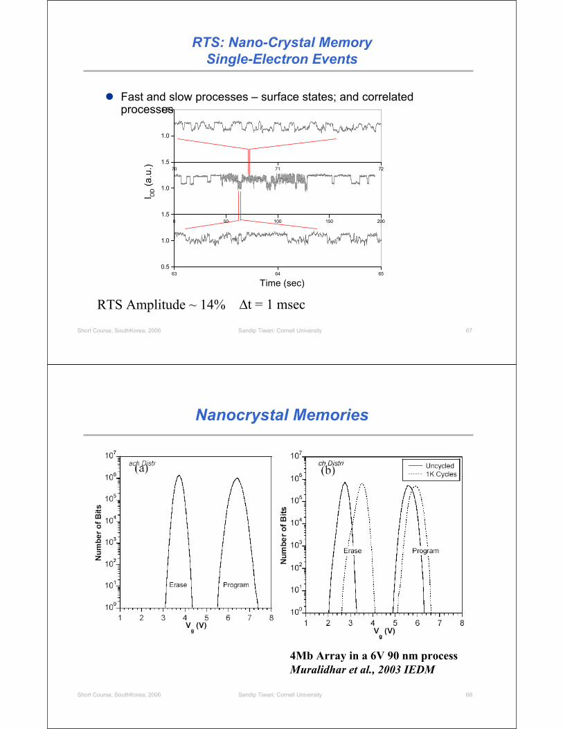
RTS: Nano-Crystal MemorySingle-Electron Events
Fast and slow processes – surface states; and correlated processes
63 64 650.5
1.0
1.5
Time (sec)
0 50 100 150 200
1.0
1.5
I DD (a
.u.) 70 71 72
1.0
1.5
t = 1 msecRTS Amplitude ~ 14%
Sandip Tiwari; Cornell University 68Short Course, SouthKorea, 2006
Nanocrystal Memories
4Mb Array in a 6V 90 nm processMuralidhar et al., 2003 IEDM

Sandip Tiwari; Cornell University 69Short Course, SouthKorea, 2006
-2 0 2 4 610-13
10-12
10-11
10-10
10-9
10-8
10-7
10-6I D
D(A
)
VG(V)
Scaled Front-Side SONOS Memories
10 nm
Poly-silicon Gate
silicon
oxidenitride
L = 46 nm, W = 33 nmONO stack = 2 / 6 / 12 nm
V = 2.7 V
Kim et al., IEEE SNW (2003)
100 101 102 103 104 1050.80.91.01.11.21.31.41.51.6
WriteErase
Thre
shol
d V
olta
ge (V
)
Write/Erase CyclingNitride
10 nm
Gate
Source
Drain
Use of higher defect density to counter statistical effects
Sandip Tiwari; Cornell University 70Short Course, SouthKorea, 2006
SONOS Memories
-2 0 2 4 610-14
10-12
10-10
10-8
10-6
I D(A
)
VG(V)
-2 0 2 4 610-14
10-12
10-10
10-8
10-6
I D(A
)
VG(V)
-2 0 2 4 610-14
10-12
10-10
10-8
10-6
I D(A
)
VG(V)-2 0 2 4 6
10-14
10-12
10-10
10-8
10-6
I D(A
)
VG(V)
W/L33nm/46nm
W/L62nm/60nm
W/L75nm/100nm
W/L90nm/100nm
A Constant Window
75electrons
Kim et al., IEEE SNW (2003)

Sandip Tiwari; Cornell University 71Short Course, SouthKorea, 2006
Memory Using Defects on Back
Silva et al. (2005)
Sandip Tiwari; Cornell University 72Short Course, SouthKorea, 2006
S = 70 mV/decade
ONO stack = 2 / 6 / 13 nm; L = 50 nm, W = 100 nm
Defects on the Back
tSi = 20 nm
VD = 1 V
Ultra-thin Si on ONO layer
-1.0 -0.5 0.0 0.5 1.010-14
10-12
10-10
10-8
10-6
I DD
, IG
(A)
VG (V)

Sandip Tiwari; Cornell University 73Short Course, SouthKorea, 2006
-1.0 -0.5 0.0 0.5 1.010-13
10-12
10-11
10-10
10-9
10-8
10-7
I DD
(A)
VG (V)
Oxide/Nitride/Oxide : 8 / 15 / 40 nm; tSi = 50 nm
VD = 100, 200 mV
0 50 100 150 2000
2
4
6
8
10
I DD
(nA)
VDD (mV)
VG – VT = 0, 0.1, …0.5 V
Single Electrons in Output Characteristics
Silva et al., IEEE SOI Conf. (2003)
Sandip Tiwari; Cornell University 74Short Course, SouthKorea, 2006
Source
Drain
InsulatorBack Gate
Carbon Nanotube
dt ~ 1.8 nm 10-nm SiO2
10-5
10-4
10-3
10-2
10-1
100
101
Id [
A]
-2 -1 0 1 2Vgs[V]
Vds = -0.9 V -0.7 V -0.5 V -0.3 V -0.1 V
Subthreshold Characteristics Output Characteristics
Carbon Nanotube Field-Effect Transistor
10
8
6
4
2
0
I d [
A]
-1.2 -0.8 -0.4 0.0Vds [V]
Vgs = 0.4 to -1.6 VStep -0.4V
200 nm
CNT
Ti Ti

Sandip Tiwari; Cornell University 75Short Course, SouthKorea, 2006
CB: conduction bandVB: valence band
Vgs < 0
h+
source drainEF VB
CB
Vds < 0
Vgs > 0
VB
CB EFe-
10-5
10-4
10-3
10-2
10-1
100
101
Id [
A]
-2 -1 0 1 2Vgs[V]
Vds = -0.9 V -0.7 V -0.5 V -0.3 V source
drain
Vds < 0
ox t~ t d
Gate oxide: 10-nm SiO2Contact metal: Ti
PRL 87, 256805 (2001)PRL 89, 106801 (2002)APL 83, 2435 (2003)
Nanotube FETs
1D (ultra-thin body) channelBallistic transport (at low Vds) Switching can be dominated by the contact Schottky barriers
Screening lengthBarrier width ~ oxide thickness tox (on-state)Ambipolar behavior
Sandip Tiwari; Cornell University 76Short Course, SouthKorea, 2006
10-7
10-6
10-5
10-4
10-3
10-2
10-1
I d (
A)
-2.0 -1.5 -1.0 -0.5 0.0
Vg-Si (V)
Vds = -0.5 V
Id vs. Si gate voltage Vg-Si
Contact Switching
S~100 mV/dec
Theoretical limit: S ~ 60 mV/dec
Drain current Id vs. Al gate voltage Vg-Al
10-8
10-7
10-6
10-5
10-4
10-3
10-2
10-1
I d (
A)
-1.2 -0.8 -0.4 0.0
Vg-Al (V)
Vgs-Si = -2.5 V
S~63 mV/dec
Bulk Switching
IBM
Performance

Sandip Tiwari; Cornell University 77Short Course, SouthKorea, 2006
Band to Band Tunneling in Nanotubes
The semiconductor is one-dimensionalThe body of the semiconductor is ultra-thinTransport in the semiconductor is ballisticThe effective masses of electrons and holes are smallThe effective masses of electrons and holes are similarThe semiconductor has a direct band gap
Sandip Tiwari; Cornell University 78Short Course, SouthKorea, 2006
Molecule as Filter
Molecular state spectrum shifts with gate potentialSymmetric molecule with unity peak resonant transmissionState spectrum fixed relative to central molecular potential.Electrochemical potentials represented by source & drain (n or p) Fermi levelsState occupancy is 0 above VP, 1 below VN and ½ between VN and VPCharge in filled state = # of electrons in orbital represented by that stateCentral Potential given by electrostatic coupling to S, D and G potentials and increased by Qsc/CPolarization by fixed diel. permittivity.
VA = 0
VB
VB
VB
VB
VG=0BGG VVV
2)1(
VG=0.3V
VG=1.0 V
Lang, Solomon, Kagan, FME & APS Mar. Mtg. (2005)

Sandip Tiwari; Cornell University 79Short Course, SouthKorea, 2006
Molecules and Self-Assembly
If molecule mimics MOSFETFor gate field to penetrate molecular channel
Dielectric thickness to be comparable to the molecular lengthIntimacy between molecule gate dielectricMolecule sufficiently long and chemically functionalized and thegate dielectric is sufficiently thick to limit tunneling between source and drain electrodes and to ensure an “OFF” state of the device and between source-gate
If self-assembly used as a technique for fabricationLow energy scales of assembly process (~ eV)Higher defect rate with consequences for larger scale
Is current sufficient
Short Course, SouthKorea, 2006
Circuits and Systems

Sandip Tiwari; Cornell University 81Short Course, SouthKorea, 2006
Stability and Signal Recovery
Analog: open & closed loop/feedbackRegenerative effects and signal stability issues
DigitalSignal restoration using gain
Feedback between input and output (Z2, e.g.) leads to a larger input load because the 180o phase shift during amplificationAt the input C appears as (K+1)C (Miller effect )
12
KZZin
Vin
VoutK
Vin
VoutK= KVin 1
1
2
1
2 111ZZ
KZZ
VV
in
out
Vin
VoutK
Z2
Z1
Sandip Tiwari; Cornell University 82Short Course, SouthKorea, 2006
Devices and Circuits
Digital CMOS design:
Only two circuit forms matter(maybe three)
Static CMOS, and Dynamic CMOS
These forms employed because:
They are not highly demanding of devices because of power gain
So they work with transistors
Robust, especially static circuitsCLK

Sandip Tiwari; Cornell University 83Short Course, SouthKorea, 2006
Sensing
Sandip Tiwari; Cornell University 84Short Course, SouthKorea, 2006
Sensing
tRAC tAA

Sandip Tiwari; Cornell University 85Short Course, SouthKorea, 2006
MRAM Designs
5001Density Index
16 +1 capacitor11+1capacitor11No. of Transistors []
44.62176.67179.37Power [uW]
70.026.166.96Read time [ns]
Self-referencingAveragingTwin
Differential Amplifier DesignTwin Cell
Averaging
Self-Referencing
Source: Sudheeran and Chang (2006)
Short Course, SouthKorea, 2006
a)
b)
10 m
Drain
Source
AlternateDrain
GateCatalyst Pad
100 m*
Vsd
50
Bias TeeSignal Generator
ImixVg
Gate
HR-Si
SiO2
SiO2
Drain
NT
Source -3 -2 -1 0
0
100
200
0
50
100
150
Gdc
SI m
ix(n
A)
I mod
el(n
A)
Vg (V)
a)
b)
0
1
2
3
4
2)(41 ac
sg
mix VVGI
f = 10 MHz
Mixing signal for ac applied to source:
ssgg
VVVVGI )2/|(|FET transistor:
NT Mixer/Transistor

Sandip Tiwari; Cornell University 87Short Course, SouthKorea, 2006
-2.0 -1.5 -1.0 -0.50
102030405060
0
1
2
3
4
G
(ps)
Vg (V)
G (
S)
Setup-limited
Device-limited
0.1 1 10
0.1
1
10
100
-0.3 V-0.5 V-0.7 V-1.2 V
-3 -2 -1 0-100
0
100
200
0
5
1010 MHz
50 GHz
I mix
(nA
)
Frequency (GHz)
Mixing signal versus frequency
High freq. roll off caused by setup,not device (except near turnoff)
Time constant of rolloff versus Vg
Device
Setup
setup = RC
NT FET mixer operates up to 50 GHzRosenblatt et al. , APL (2005)
NT Mixer/Transistor up to 50 GHz
Sandip Tiwari; Cornell University 88Short Course, SouthKorea, 2006
Classical vs. Quantum Computing
Classical bit: 1 (On) and 0 (Off)Stable pointer states of the computer hardware
Quantum bit: Qubit (superposition of two states)
Every two level system can serve as qubitFor any digital computer, its set of computational states is some set of mutually distinguishable abstract states
The specific computational state that is in use at a given time represents the specific digital data currently being processed within the machineIn quantum computing the computational state is not always a pointer state

Sandip Tiwari; Cornell University 89Short Course, SouthKorea, 2006
Classical versus Quantum Bit
Sandip Tiwari; Cornell University 90Short Course, SouthKorea, 2006
The Square Root of NOT
If input is either basis state (0 or 1) you get a state that appears random when measured…
But if you feed the output back into another N1/2 without measuring it, you get the inverse of the original value!
“How is thatpossible?”
N1/20 0 (50%)1 (50%)
N1/21 0 (50%)1 (50%)
N1/20 0 (50%)1 (50%)
N1/2 1
N1/20 0 (50%)1 (50%)
N1/2 0

Sandip Tiwari; Cornell University 91Short Course, SouthKorea, 2006
NOT1/2: Unitary Implementation
1
010
21
21
21
21
: ii
ii
N NN 10
10
01102
1002
12
1
2
21
01 ii
ii
i
NN
Prob. ½ Prob. ½
Sandip Tiwari; Cornell University 92Short Course, SouthKorea, 2006
Optical Implementation of N1/2
Beam splitters (semi-silvered mirrors) form superpositions of reflected and transmitted photon states
“0”
“1”
“1”
“1”
“0”
“0”
“1”“1”
laser
Sandip Tiwari; Cornell University 93Short Course, SouthKorea, 2006
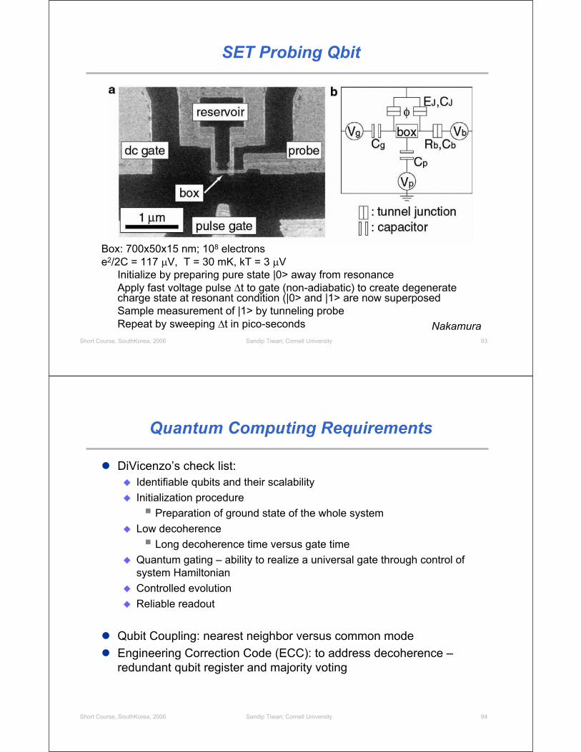
SET Probing Qbit
Box: 700x50x15 nm; 108 electronse2/2C = 117 V, T = 30 mK, kT = 3 V
Initialize by preparing pure state |0> away from resonanceApply fast voltage pulse t to gate (non-adiabatic) to create degenerate charge state at resonant condition (|0> and |1> are now superposedSample measurement of |1> by tunneling probeRepeat by sweeping t in pico-seconds Nakamura
Sandip Tiwari; Cornell University 94Short Course, SouthKorea, 2006
Quantum Computing Requirements
DiVicenzo’s check list:Identifiable qubits and their scalabilityInitialization procedure
Preparation of ground state of the whole systemLow decoherence
Long decoherence time versus gate timeQuantum gating – ability to realize a universal gate through control of system HamiltonianControlled evolutionReliable readout
Qubit Coupling: nearest neighbor versus common modeEngineering Correction Code (ECC): to address decoherence –redundant qubit register and majority voting

Short Course, SouthKorea, 2006
Systems, Hierarchy, Complexity and Architecture
A critical look
Sandip Tiwari; Cornell University 96Short Course, SouthKorea, 2006
Molecular Memories?
Memory by using switching behavior in a crosspoint configurationLogic by diode logic with open and diode cross-points and resistors (!)
Cur
rent
(mA
)
Voltage (V)
-10
-5
0
5
10
-2.0 -1.0 0.0 1.0
molecular switch
HP

Sandip Tiwari; Cornell University 97Short Course, SouthKorea, 2006
Molecular: 2 terminals or 3 terminals?
Customized combinatorial logic scales polynomiallywith function size (~N2).Array logic scales exponentially with function size(~22N)Array peripherals scale in proportion to function size
UCLA, CalTech, HP
Sandip Tiwari; Cornell University 98Short Course, SouthKorea, 2006
CMOL
CMOL combines: - (relatively sparse, but highly functional) CMOS subsystem- very dense nanowire crossbar, and- a molecular-scale device at each nanowire crosspoint
CMOSstack(onlya few metallayers
shown)
interface pins
metallicnanowiring
levels
MOSFET
self-assembledmolecular devices
interfacepin
Si wafer
Likharev (2003)

Sandip Tiwari; Cornell University 99Short Course, SouthKorea, 2006
CMOL
selectednanodevice
selected word
nanowire
selected bitnanowire interface
pin 1interface
pin 2CMOScell 2
CMOScell 1
2 FCMOS
2Fnano
pin 1
pin 2’
pin 2
2rFnano
Nanodevice addressed via two CMOS cells
Each and every nanodevice may be addressed!
Tilt = sin-1(Fnano/ FCMOS)
Likharev (2003)
Sandip Tiwari; Cornell University 100Short Course, SouthKorea, 2006
CMOL FPGACMOS inverters + nanodevice latches for (re)configuration
(a)2 FCMOS 2 FCMOS 2(r - 1)
(b)
output nanowire
inputnanowire
CMOS column 2
CMOSrow 1
CMOSinverter
CMOScolumn 1
CMOSrow 2
VDD
CMOL FPGA fabric
B
A
FF
A B
CMOS inverter
nanodevices
passtransistor
AB
F
(c)
RO
N
RpassCwire
Likharev (2005)

Sandip Tiwari; Cornell University 101Short Course, SouthKorea, 2006
NanoFabrics
deHon (2004)
Sandip Tiwari; Cornell University 102Short Course, SouthKorea, 2006
Speed Gaps in Processor Hierarchy
Source: T.C. Mowry
dRAM
sRAM
CPU

Sandip Tiwari; Cornell University 103Short Course, SouthKorea, 2006
3-D Microprocessors
Goal of improving logic-memory interactions and to compensate logic and memory performance divergence
Current designs exceedingly complex (-> power^ ) focused onSuperscalar (> 1 inst/cycle), out-of-order execution, instruction-level parallelism, hiding memory latency, …
3-D in P:High density, low latency, large bandwidth
m separationVertical connections throughout the design area
Sandip Tiwari; Cornell University 104Short Course, SouthKorea, 2006
Latency and Bandwidth
2-D: Connections on the peripheryLong global connectionsCPU to off-chip main memory with latency and misses
3-D: Connections across the areaConnections short + verticalSuitable for high-bandwidth and vector operationsNo pin cost, large block access of data
CPU
Memory
CPU
Memory
The following example uses a baseline 2-D processor core representative of current technology3 GHz CPU, 750 MHz memory, 64 KB L1I, 64 KB L1D, 1 MB L2
Latency: Important for random access (servers, e.g.), single coreBandwidth: Multiple cores, multi-threads, graphics

Sandip Tiwari; Cornell University 105Short Course, SouthKorea, 2006
Expanding L2 Cache
Performance peaks at 8 MB for integer programs with standard DRAM Example of trade-off between fitting the working data (4-16 MB for integer programs) into the cache (better performance) and increased access latency for larger caches (worse performance)
Larger working data of floating-point programs continue to improve with cache size despite cache hit latency with large cache size
Floating-point programs
2 MB 4 MB 8 MB 16 MB 32 MB 64 MB0
20
40
60
80
100
120
140
On-chip DRAMw/ 1 MB L2
Ave
rage
spe
edup
ove
rba
selin
e 2-
D p
roce
ssor
(%)
L2 cache size
Standard DRAM Standard DRAM + stream prefetch On-chip DRAM + stream prefetch
Perfect L2
C. C. Liu .. Tiwari., IEEE D&T Mag. (2005)
SPEC2000 Integer programs
2 MB 4 MB 8 MB 16 MB 32 MB 64 MB0
20
40
60
On-chip DRAMw/ 1 MB L2
Ave
rage
spe
edup
ove
rba
selin
e 2-
D p
roce
ssor
(%)
L2 cache size
Standard DRAM Standard DRAM +
stream prefetch On-chip DRAM +
stream prefetch
Perfect L2
Sandip Tiwari; Cornell University 106Short Course, SouthKorea, 2006
L2/L3 Cache Sizing with Stream Prefetching
Performance within 8-10% of perfect L2Large speedups achievable with small L2/L3 cache because of significant reduction in main memory latencyHierarchy critical to performance
Floating-point programs
2 MB 4 MB 8 MB 16 MB 32 MB 64 MB
20
40
60
80
100
120
140
On-chip DRAM w/ 1 MB L2 (no L3)
On-chip DRAM +stream prefetch
Standard DRAM +stream prefetch
Ave
rage
spe
edup
ove
rba
selin
e 2-
D p
roce
ssor
(%)
L3 cache size
L2 = 1 MB L2 = 2 MB L2 = 4 MB L2 = 8 MB
Standard DRAM
Perfect L2
C. C. Liu .. Tiwari., IEEE D&T Mag. (2005)

Sandip Tiwari; Cornell University 107Short Course, SouthKorea, 2006
Complexity
Rent’s Rule: Terminal count is related to number of gates (at all hierarchical levels)
T = t Np
(0<p<1; t is number of terminals per logic block) p=1 is un-optimized placement
Number of interconnections among a group of sub-components at any level is proportional to the total terminal count of all the sub-componentsWith placement optimization (p<1), only a fraction of logic blocks accessible
This accessibility defines how much of the circuitry do iterative testing procedures access and test for usefulnessIf logic blocks defective: Naccessible ~ ((1-dLOGIC)N)p
If wiring defective, the number of testable logic blocks: Naccessible ~ (1-dLOGIC) Np
a considerably more serious problem
Sandip Tiwari; Cornell University 108Short Course, SouthKorea, 2006
Configurability: Defects and Testing
Suppose, we work with 105 logic blocks, each employing 1000 device elementsWhat does it mean that one can work with chips that are 90% functional (or that 10% of logic blocks are faulty)
If the probability of failure is p for each element, probability of a logic block being functional is (1-p)1000
Rate of connectivity is non-linearly related to defects, and affects congestion, power, ….Probability of 90% yield in logic blocks implies 1 in 104 device level faults
We still need extremely high reproducibility and yield

Sandip Tiwari; Cornell University 109Short Course, SouthKorea, 2006
Observability in Presence of Defects
Testing of N modules in a defect-free system
Percentage of modules tested/testable in presence
of interconnect defects
Usable logic blocks of a chip reduces rapidly with interconnect defects since their correctness can not be tested.Testability is cumbersome. Kumar, DFT (2004)
Sandip Tiwari; Cornell University 110Short Course, SouthKorea, 2006
Interconnect Defect Penalty
Kumar, DFT (2004)

Sandip Tiwari; Cornell University 111Short Course, SouthKorea, 2006
Conclusion
Nanoelectronics will certainly be evolutionary, and may be revolutionary
Complex applications (beyond sensing, …) require a systematic, robust and reproducible framework that requires a number of properties across scales
Logic applications will require 3-D structures and non-Manhattan layouts
These usually do not work with “bottoms-up” approachesMultiplexing schemes to manage the interconnect pitch transformation from nano- to microscale require real estateCharge-based devices at nanoscale have inherent power dissipation problemsOther approaches, spin-based or photon-based or others, need to demonstrate size scale, gain and ability to transform signal to charge and vice versa for connection to the external world