sanitary equipment design principles checklist & glossary
TRANSCRIPT
Sanitary Equipment Design PrinciplesCHECKLIST & GLOSSARY
JANUARY 2014
EDITION
F O U N D AT I O N F O R
R E S E A R C H E D U C A T I O NM E AT P O U LT R Y
2014 Sanitary Equipment Design Taskforce
Boar’s Head Provisions Co., Inc.
Cargill Meat Solutions Ed Miniat, Inc.
Hillshire Brands Hormel Foods Corporation
Kraft Foods, Inc. Land O’Frost, Inc.
Maple Leaf Foods, Inc. OSI Group
Smithfield Foods, Inc. Tyson Foods, Inc.
Copyright © 2016 by the Foundation for Meat and Poultry Research and Education. All rights reserved.
Revised:October 2014
Recommended Citation 2013 Sanitary Equipment Design Taskforce (ed.). 2014. Sanitary equipment design principles: checklist & glossary. AMI Foundation, Washington, D.C.
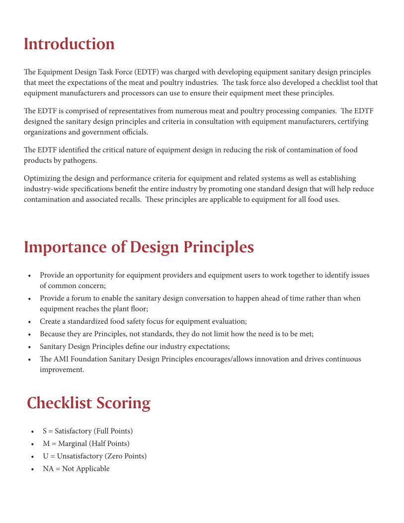
IntroductionThe Equipment Design Task Force (EDTF) was charged with developing equipment sanitary design principles that meet the expectations of the meat and poultry industries. The task force also developed a checklist tool that equipment manufacturers and processors can use to ensure their equipment meet these principles.
The EDTF is comprised of representatives from numerous meat and poultry processing companies. The EDTF designed the sanitary design principles and criteria in consultation with equipment manufacturers, certifying organizations and government officials.
The EDTF identified the critical nature of equipment design in reducing the risk of contamination of food products by pathogens.
Optimizing the design and performance criteria for equipment and related systems as well as establishing industry-wide specifications benefit the entire industry by promoting one standard design that will help reduce contamination and associated recalls. These principles are applicable to equipment for all food uses.
Importance of Design Principles• Provide an opportunity for equipment providers and equipment users to work together to identify issues
of common concern;• Provide a forum to enable the sanitary design conversation to happen ahead of time rather than when
equipment reaches the plant floor;• Create a standardized food safety focus for equipment evaluation;• Because they are Principles, not standards, they do not limit how the need is to be met;• Sanitary Design Principles define our industry expectations;• The AMI Foundation Sanitary Design Principles encourages/allows innovation and drives continuous
improvement.
Checklist Scoring• S = Satisfactory (Full Points)• M = Marginal (Half Points)• U = Unsatisfactory (Zero Points)• NA = Not Applicable
2
10 Principles of Sanitary Design
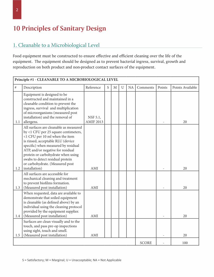
Food equipment must be constructed to ensure effective and efficient cleaning over the life of the equipment. The equipment should be designed as to prevent bacterial ingress, survival, growth and reproduction on both product and non-product contact surfaces of the equipment.
1. Cleanable to a Microbiological Level
Principle #1 - CLEANABLE TO A MICROBIOLOGICAL LEVEL
# Description Reference S M U NA Comments Points Points Available
1.1
Equipment is designed to be constructed and maintained in a cleanable condition to prevent the ingress, survival and multiplication of microorganisms (measured post installation) and the removal of allergens.
NSF 5.1, AMIF 2013 - 20
1.2
All surfaces are cleanable as measured by <1 CFU per 25 square centimeters, <1 CFU per 10 ml when the item is rinsed, acceptable RLU (device specific) when measured by residual ATP, and/or negative for residual protein or carbohydrate when using swabs to detect residual protein or carbohydrate. (Measured post installation) AMI - 20
1.3
All surfaces are accessible for mechanical cleaning and treatment to prevent biofilms formation. (Measured post installation) AMI - 20
1.4
When requested, data are available to demonstrate that soiled equipment is cleanable (as defined above) by an individual using the cleaning protocol provided by the equipment supplier. (Measured post installation) AMI - 20
1.5
Surfaces are clean visually and to the touch, and pass pre-op inspections using sight, touch and smell. (Measured post installation) AMI - 20
SCORE - 100
S = Satisfactory; M = Marginal; U = Unacceptable; NA = Not Applicable
3
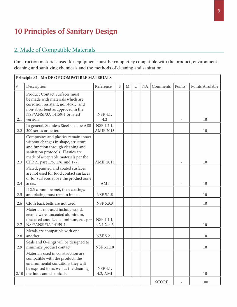
Construction materials used for equipment must be completely compatible with the product, environment, cleaning and sanitizing chemicals and the methods of cleaning and sanitation.
2. Made of Compatible Materials
Principle #2 - MADE OF COMPATIBLE MATERIALS
# Description Reference S M U NA Comments Points Points Available
2.1
Product Contact Surfaces must be made with materials which are corrosion resistant, non-toxic, and non-absorbent as approved in the NSF/ANSI/3A 14159-1 or latest version.
NSF 4.1, 4.2 - 10
2.2In general, Stainless Steel shall be AISI 300 series or better.
NSF 4.2.1, AMIF 2013 - 10
2.3
Composites and plastics remain intact without changes in shape, structure and function through cleaning and sanitation protocols. Plastics are made of acceptable materials per the CFR 21 part 175, 176, and 177. AMIF 2013 - 10
2.4
Plated, painted and coated surfaces are not used for food contact surfaces or for surfaces above the product zone areas. AMI - 10
2.5If 2.3 cannot be met, then coatings and plating must remain intact. NSF 5.1.8 - 10
2.6 Cloth back belts are not used NSF 5.3.3 10
2.7
Materials not used include wood, enamelware, uncoated aluminum, uncoated anodized aluminum, etc. per NSF/ANSI/3A 14159-1.
NSF 4.1.1, 4.2.1.2, 4.3 10
2.8Metals are compatible with one another. NSF 5.2.1 10
2.9Seals and O-rings will be designed to minimize product contact. NSF 5.1.10 10
2.10
Materials used in construction are compatible with the product, the environmental conditions they will be exposed to, as well as the cleaning methods and chemicals.
NSF 4.1, 4.2, AMI 10
SCORE - 100
10 Principles of Sanitary Design
4
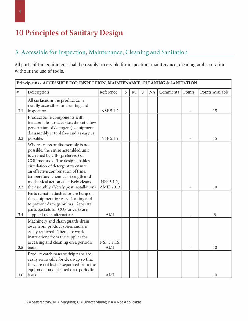
All parts of the equipment shall be readily accessible for inspection, maintenance, cleaning and sanitation without the use of tools.
3. Accessible for Inspection, Maintenance, Cleaning and Sanitation
Principle #3 - ACCESSIBLE FOR INSPECTION, MAINTENANCE, CLEANING & SANITATION
# Description Reference S M U NA Comments Points Points Available
3.1
All surfaces in the product zone readily accessible for cleaning and inspection. NSF 5.1.2 - 15
3.2
Product zone components with inaccessible surfaces (i.e., do not allow penetration of detergent), equipment disassembly is tool free and as easy as possible. NSF 5.1.2 - 15
3.3
Where access or disassembly is not possible, the entire assembled unit is cleaned by CIP (preferred) or COP methods. The design enables circulation of detergent to ensure an effective combination of time, temperature, chemical strength and mechanical action effectively cleans the assembly. (Verify post installation)
NSF 5.1.2, AMIF 2013 - 10
3.4
Parts remain attached or are hung on the equipment for easy cleaning and to prevent damage or loss. Separate parts baskets for COP or carts are supplied as an alternative. AMI - 5
3.5
Machinery and chain guards drain away from product zones and are easily removed. There are work instructions from the supplier for accessing and cleaning on a periodic basis.
NSF 5.1.16, AMI - 10
3.6
Product catch pans or drip pans are easily removable for clean-up so that they are not lost or separated from the equipment and cleaned on a periodic basis. AMI 10
10 Principles of Sanitary Design
S = Satisfactory; M = Marginal; U = Unacceptable; NA = Not Applicable
5
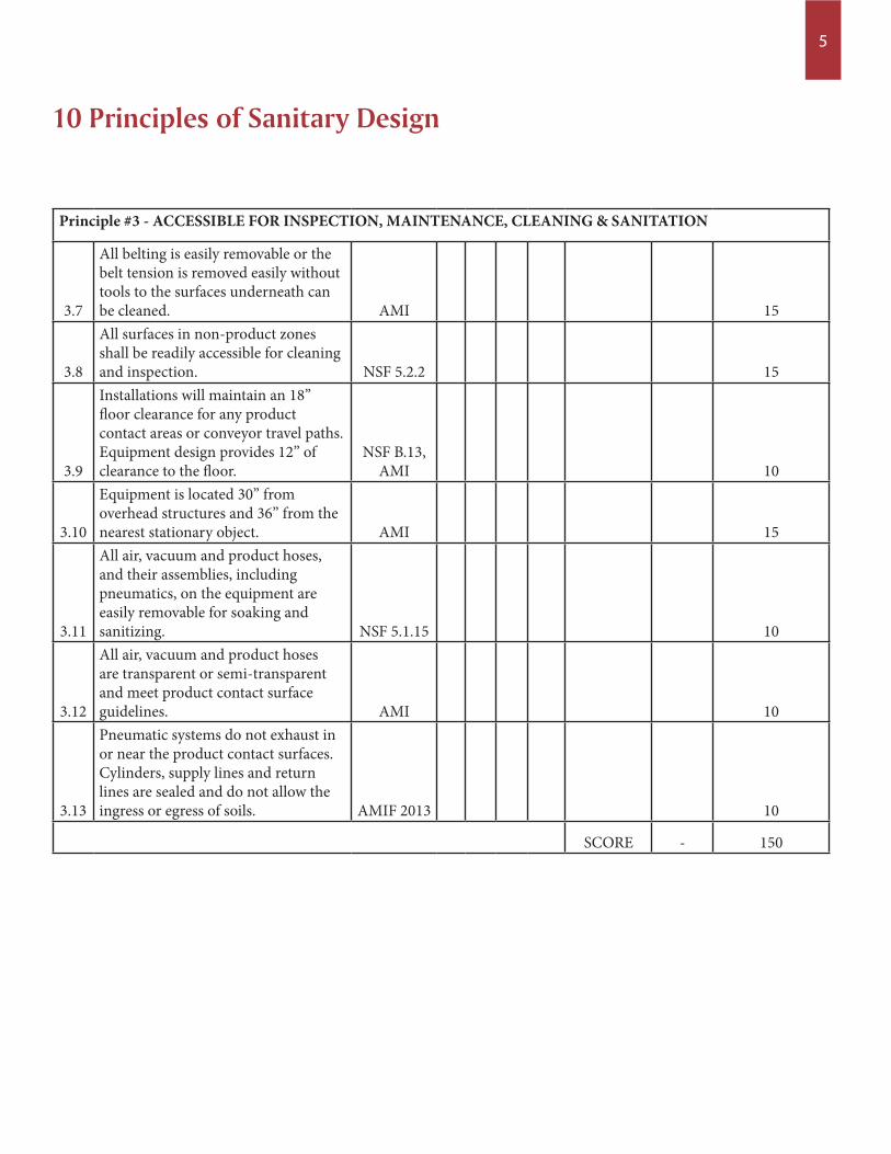
Principle #3 - ACCESSIBLE FOR INSPECTION, MAINTENANCE, CLEANING & SANITATION
3.7
All belting is easily removable or the belt tension is removed easily without tools to the surfaces underneath can be cleaned. AMI 15
3.8
All surfaces in non-product zones shall be readily accessible for cleaning and inspection. NSF 5.2.2 15
3.9
Installations will maintain an 18” floor clearance for any product contact areas or conveyor travel paths. Equipment design provides 12” of clearance to the floor.
NSF B.13, AMI 10
3.10
Equipment is located 30” from overhead structures and 36” from the nearest stationary object. AMI 15
3.11
All air, vacuum and product hoses, and their assemblies, including pneumatics, on the equipment are easily removable for soaking and sanitizing. NSF 5.1.15 10
3.12
All air, vacuum and product hoses are transparent or semi-transparent and meet product contact surface guidelines. AMI 10
3.13
Pneumatic systems do not exhaust in or near the product contact surfaces. Cylinders, supply lines and return lines are sealed and do not allow the ingress or egress of soils. AMIF 2013 10
SCORE - 150
10 Principles of Sanitary Design
6
10 Principles of Sanitary Design
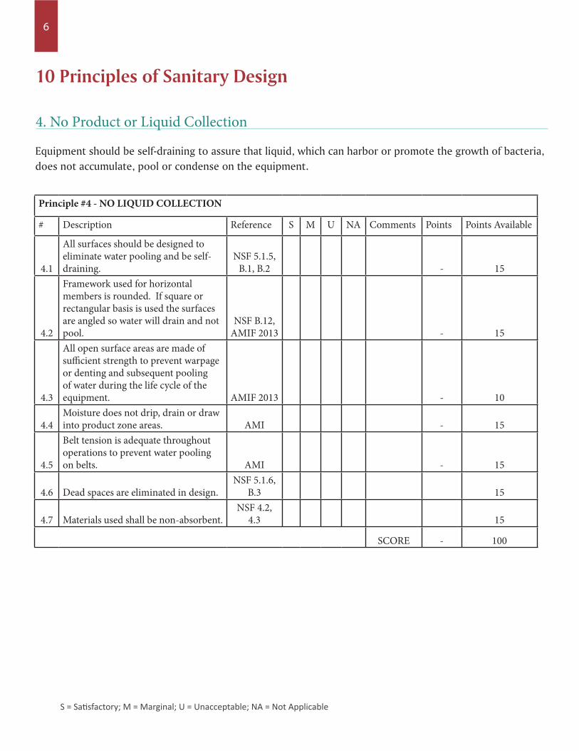
Equipment should be self-draining to assure that liquid, which can harbor or promote the growth of bacteria, does not accumulate, pool or condense on the equipment.
4. No Product or Liquid Collection
Principle #4 - NO LIQUID COLLECTION
# Description Reference S M U NA Comments Points Points Available
4.1
All surfaces should be designed to eliminate water pooling and be self-draining.
NSF 5.1.5, B.1, B.2 - 15
4.2
Framework used for horizontal members is rounded. If square or rectangular basis is used the surfaces are angled so water will drain and not pool.
NSF B.12, AMIF 2013 - 15
4.3
All open surface areas are made of sufficient strength to prevent warpage or denting and subsequent pooling of water during the life cycle of the equipment. AMIF 2013 - 10
4.4Moisture does not drip, drain or draw into product zone areas. AMI - 15
4.5
Belt tension is adequate throughout operations to prevent water pooling on belts. AMI - 15
4.6 Dead spaces are eliminated in design.NSF 5.1.6,
B.3 15
4.7 Materials used shall be non-absorbent.NSF 4.2,
4.3 15
SCORE - 100
S = Satisfactory; M = Marginal; U = Unacceptable; NA = Not Applicable
7
10 Principles of Sanitary Design
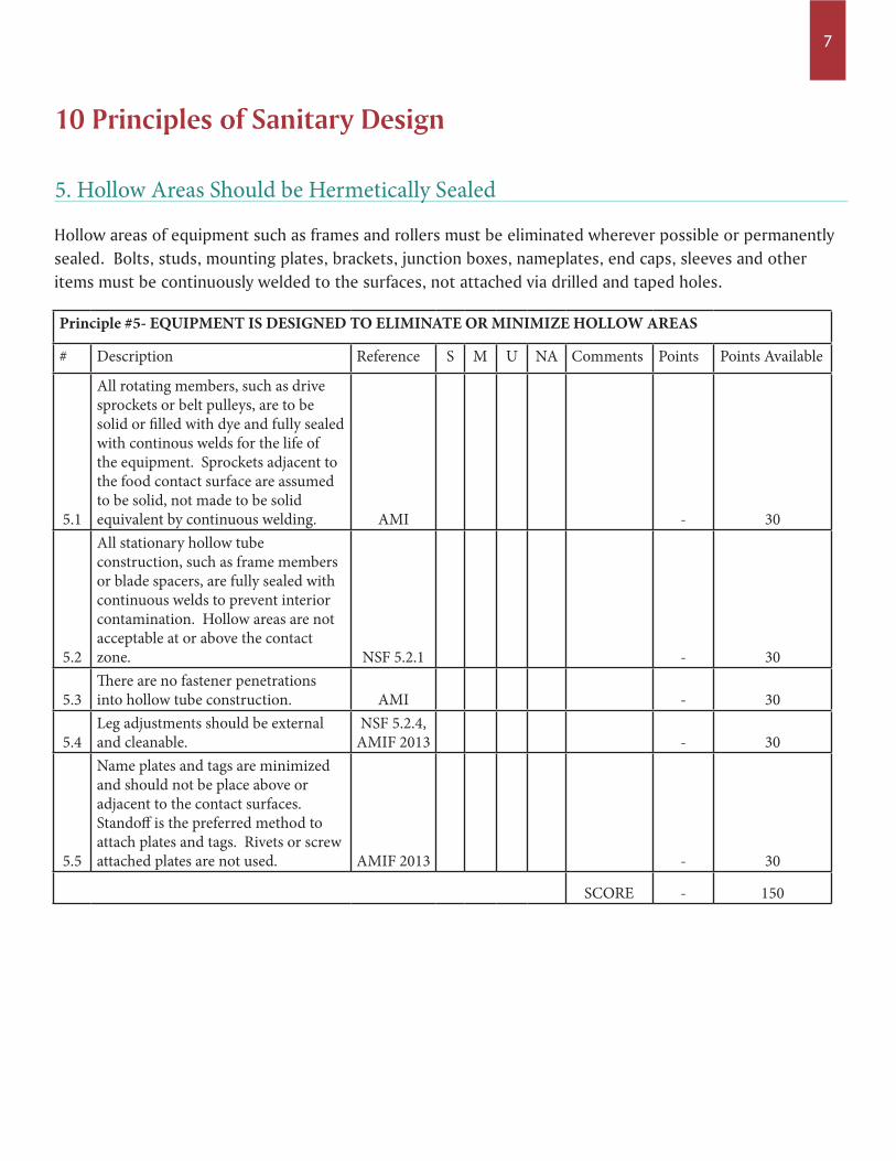
Hollow areas of equipment such as frames and rollers must be eliminated wherever possible or permanently sealed. Bolts, studs, mounting plates, brackets, junction boxes, nameplates, end caps, sleeves and other items must be continuously welded to the surfaces, not attached via drilled and taped holes.
5. Hollow Areas Should be Hermetically Sealed
Principle #5- EQUIPMENT IS DESIGNED TO ELIMINATE OR MINIMIZE HOLLOW AREAS
# Description Reference S M U NA Comments Points Points Available
5.1
All rotating members, such as drive sprockets or belt pulleys, are to be solid or filled with dye and fully sealed with continous welds for the life of the equipment. Sprockets adjacent to the food contact surface are assumed to be solid, not made to be solid equivalent by continuous welding. AMI - 30
5.2
All stationary hollow tube construction, such as frame members or blade spacers, are fully sealed with continuous welds to prevent interior contamination. Hollow areas are not acceptable at or above the contact zone. NSF 5.2.1 - 30
5.3There are no fastener penetrations into hollow tube construction. AMI - 30
5.4Leg adjustments should be external and cleanable.
NSF 5.2.4, AMIF 2013 - 30
5.5
Name plates and tags are minimized and should not be place above or adjacent to the contact surfaces. Standoff is the preferred method to attach plates and tags. Rivets or screw attached plates are not used. AMIF 2013 - 30
SCORE - 150
8
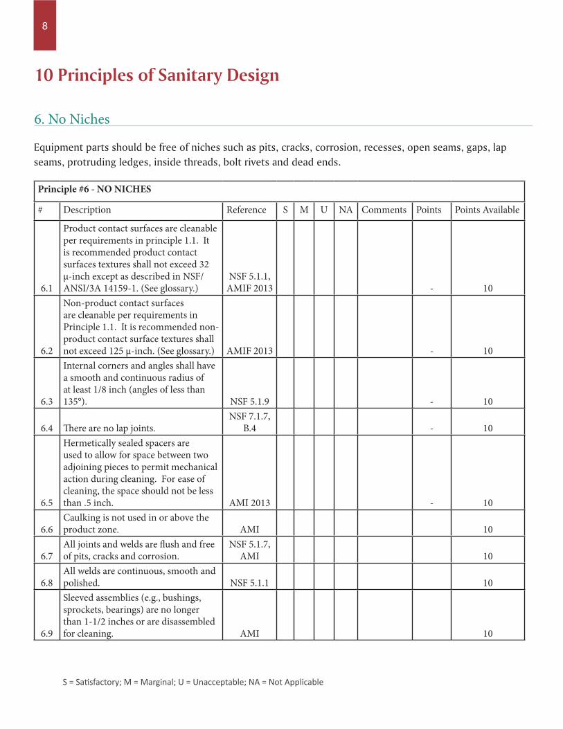
Equipment parts should be free of niches such as pits, cracks, corrosion, recesses, open seams, gaps, lap seams, protruding ledges, inside threads, bolt rivets and dead ends.
6. No Niches
Principle #6 - NO NICHES
# Description Reference S M U NA Comments Points Points Available
6.1
Product contact surfaces are cleanable per requirements in principle 1.1. It is recommended product contact surfaces textures shall not exceed 32 µ-inch except as described in NSF/ANSI/3A 14159-1. (See glossary.)
NSF 5.1.1, AMIF 2013 - 10
6.2
Non-product contact surfaces are cleanable per requirements in Principle 1.1. It is recommended non-product contact surface textures shall not exceed 125 µ-inch. (See glossary.) AMIF 2013 - 10
6.3
Internal corners and angles shall have a smooth and continuous radius of at least 1/8 inch (angles of less than 135°). NSF 5.1.9 - 10
6.4 There are no lap joints.NSF 7.1.7,
B.4 - 10
6.5
Hermetically sealed spacers are used to allow for space between two adjoining pieces to permit mechanical action during cleaning. For ease of cleaning, the space should not be less than .5 inch. AMI 2013 - 10
6.6Caulking is not used in or above the product zone. AMI 10
6.7All joints and welds are flush and free of pits, cracks and corrosion.
NSF 5.1.7, AMI 10
6.8All welds are continuous, smooth and polished. NSF 5.1.1 10
6.9
Sleeved assemblies (e.g., bushings, sprockets, bearings) are no longer than 1-1/2 inches or are disassembled for cleaning. AMI 10
10 Principles of Sanitary Design
S = Satisfactory; M = Marginal; U = Unacceptable; NA = Not Applicable
9
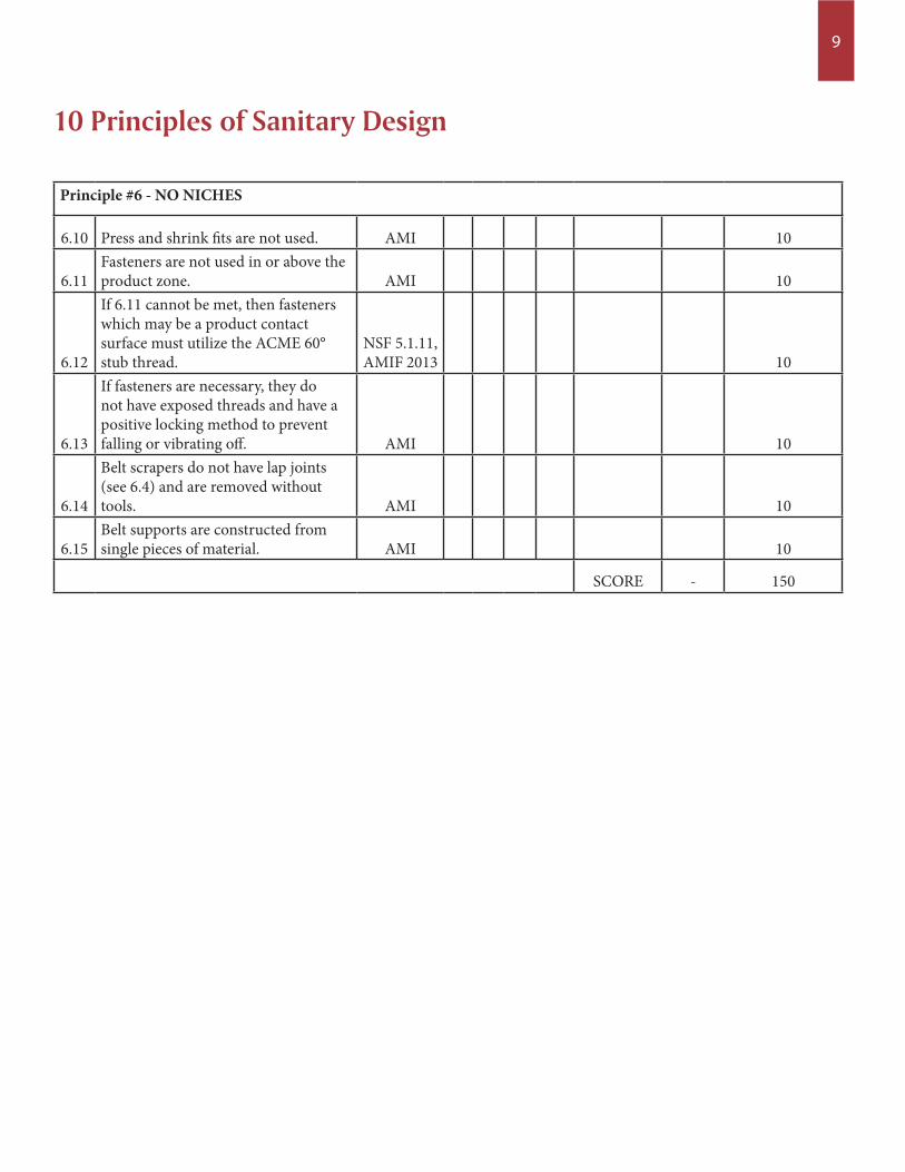
Principle #6 - NO NICHES
6.10 Press and shrink fits are not used. AMI 10
6.11Fasteners are not used in or above the product zone. AMI 10
6.12
If 6.11 cannot be met, then fasteners which may be a product contact surface must utilize the ACME 60° stub thread.
NSF 5.1.11, AMIF 2013 10
6.13
If fasteners are necessary, they do not have exposed threads and have a positive locking method to prevent falling or vibrating off. AMI 10
6.14
Belt scrapers do not have lap joints (see 6.4) and are removed without tools. AMI 10
6.15Belt supports are constructed from single pieces of material. AMI 10
SCORE - 150
10 Principles of Sanitary Design
10
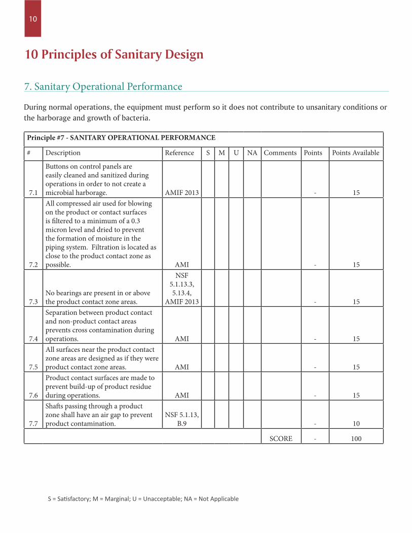
During normal operations, the equipment must perform so it does not contribute to unsanitary conditions or the harborage and growth of bacteria.
7. Sanitary Operational Performance
Principle #7 - SANITARY OPERATIONAL PERFORMANCE
# Description Reference S M U NA Comments Points Points Available
7.1
Buttons on control panels are easily cleaned and sanitized during operations in order to not create a microbial harborage. AMIF 2013 - 15
7.2
All compressed air used for blowing on the product or contact surfaces is filtered to a minimum of a 0.3 micron level and dried to prevent the formation of moisture in the piping system. Filtration is located as close to the product contact zone as possible. AMI - 15
7.3No bearings are present in or above the product contact zone areas.
NSF 5.1.13.3, 5.13.4,
AMIF 2013 - 15
7.4
Separation between product contact and non-product contact areas prevents cross contamination during operations. AMI - 15
7.5
All surfaces near the product contact zone areas are designed as if they were product contact zone areas. AMI - 15
7.6
Product contact surfaces are made to prevent build-up of product residue during operations. AMI - 15
7.7
Shafts passing through a product zone shall have an air gap to prevent product contamination.
NSF 5.1.13, B.9 - 10
SCORE - 100
10 Principles of Sanitary Design
S = Satisfactory; M = Marginal; U = Unacceptable; NA = Not Applicable
11
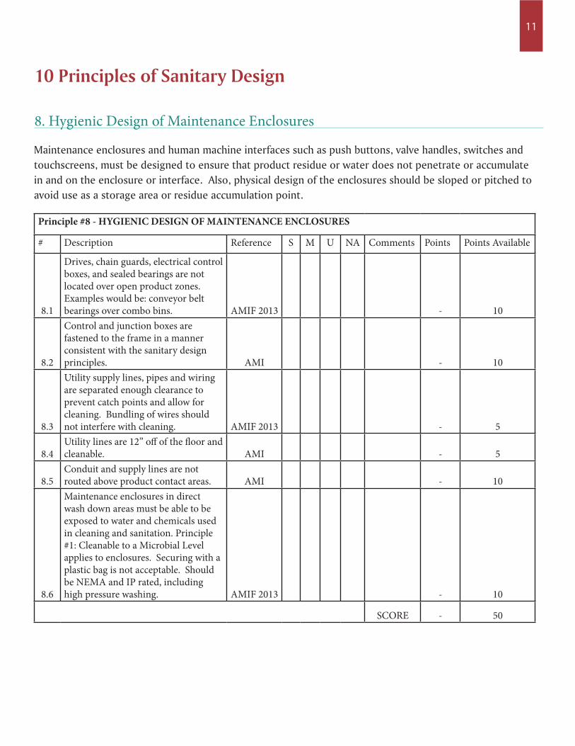
Maintenance enclosures and human machine interfaces such as push buttons, valve handles, switches and touchscreens, must be designed to ensure that product residue or water does not penetrate or accumulate in and on the enclosure or interface. Also, physical design of the enclosures should be sloped or pitched to avoid use as a storage area or residue accumulation point.
8. Hygienic Design of Maintenance Enclosures
Principle #8 - HYGIENIC DESIGN OF MAINTENANCE ENCLOSURES
# Description Reference S M U NA Comments Points Points Available
8.1
Drives, chain guards, electrical control boxes, and sealed bearings are not located over open product zones. Examples would be: conveyor belt bearings over combo bins. AMIF 2013 - 10
8.2
Control and junction boxes are fastened to the frame in a manner consistent with the sanitary design principles. AMI - 10
8.3
Utility supply lines, pipes and wiring are separated enough clearance to prevent catch points and allow for cleaning. Bundling of wires should not interfere with cleaning. AMIF 2013 - 5
8.4Utility lines are 12” off of the floor and cleanable. AMI - 5
8.5Conduit and supply lines are not routed above product contact areas. AMI - 10
8.6
Maintenance enclosures in direct wash down areas must be able to be exposed to water and chemicals used in cleaning and sanitation. Principle #1: Cleanable to a Microbial Level applies to enclosures. Securing with a plastic bag is not acceptable. Should be NEMA and IP rated, including high pressure washing. AMIF 2013 - 10
SCORE - 50
10 Principles of Sanitary Design
12
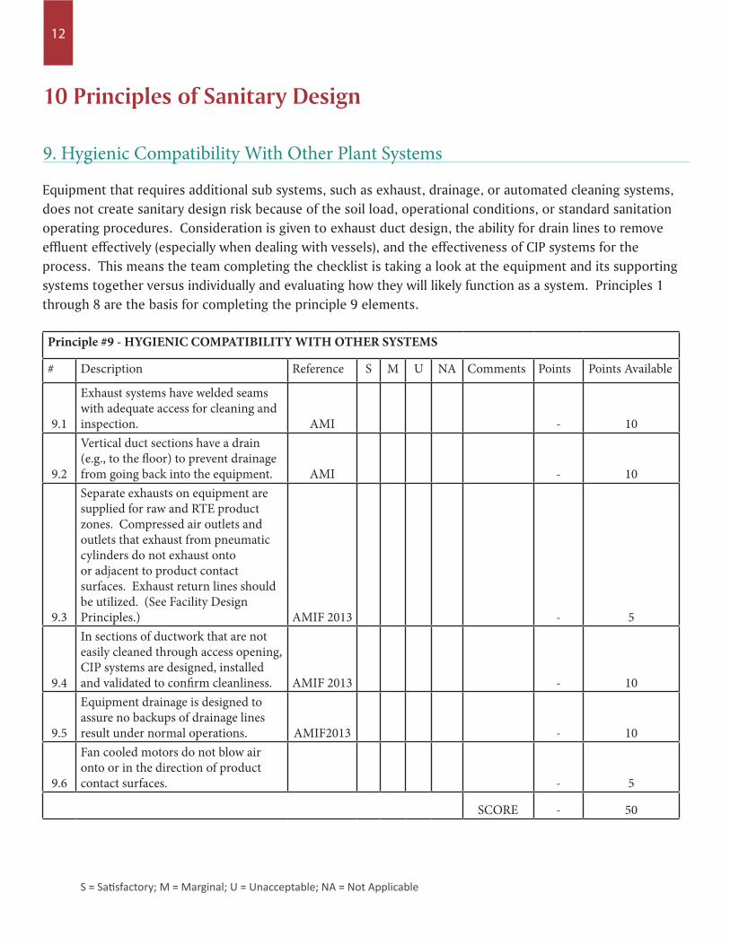
Equipment that requires additional sub systems, such as exhaust, drainage, or automated cleaning systems, does not create sanitary design risk because of the soil load, operational conditions, or standard sanitation operating procedures. Consideration is given to exhaust duct design, the ability for drain lines to remove effluent effectively (especially when dealing with vessels), and the effectiveness of CIP systems for the process. This means the team completing the checklist is taking a look at the equipment and its supporting systems together versus individually and evaluating how they will likely function as a system. Principles 1 through 8 are the basis for completing the principle 9 elements.
9. Hygienic Compatibility With Other Plant Systems
Principle #9 - HYGIENIC COMPATIBILITY WITH OTHER SYSTEMS
# Description Reference S M U NA Comments Points Points Available
9.1
Exhaust systems have welded seams with adequate access for cleaning and inspection. AMI - 10
9.2
Vertical duct sections have a drain (e.g., to the floor) to prevent drainage from going back into the equipment. AMI - 10
9.3
Separate exhausts on equipment are supplied for raw and RTE product zones. Compressed air outlets and outlets that exhaust from pneumatic cylinders do not exhaust onto or adjacent to product contact surfaces. Exhaust return lines should be utilized. (See Facility Design Principles.) AMIF 2013 - 5
9.4
In sections of ductwork that are not easily cleaned through access opening, CIP systems are designed, installed and validated to confirm cleanliness. AMIF 2013 - 10
9.5
Equipment drainage is designed to assure no backups of drainage lines result under normal operations. AMIF2013 - 10
9.6
Fan cooled motors do not blow air onto or in the direction of product contact surfaces. - 5
SCORE - 50
10 Principles of Sanitary Design
S = Satisfactory; M = Marginal; U = Unacceptable; NA = Not Applicable
13
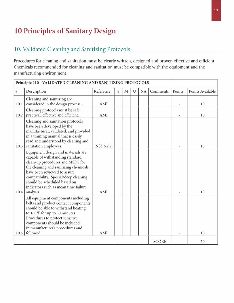
Procedures for cleaning and sanitation must be clearly written, designed and proven effective and efficient. Chemicals recommended for cleaning and sanitation must be compatible with the equipment and the manufacturing environment.
10. Validated Cleaning and Sanitizing Protocols
Principle #10 - VALIDATED CLEANING AND SANITIZING PROTOCOLS
# Description Reference S M U NA Comments Points Points Available
10.1Cleaning and sanitizing are considered in the design process. AMI - 10
10.2Cleaning protocols must be safe, practical, effective and efficient. AMI - 10
10.3
Cleaning and sanitation protocols have been developed by the manufacturer, validated, and provided in a training manual that is easily read and understood by cleaning and sanitation employees. NSF 6.2.2 - 10
10.4
Equipment design and materials are capable of withstanding standard clean-up procedures and MSDS for the cleaning and sanitizing chemicals have been reviewed to assure compatibility. Special/deep cleaning should be scheduled based on indicators such as mean time failure analysis. AMI - 10
10.5
All equipment components including belts and product contact components should be able to withstand heating to 160°F for up to 30 minutes. Procedures to protect sensitive components should be included in manufacturer’s procedures and followed. AMI - 10
SCORE - 50
10 Principles of Sanitary Design

14
Acceptable RLU : RLU is defined as “Relative Light Unit.” Standards must be developed for each operation given the ATP monitoring tools selected for use.
Principle 1.2
Sanitary Equipment Design Glossary
Stainless Steel shall be AISI 300 series or better : The American Iron and Steel Institute (AISI) assigned the designation “type 300 stainless steel” to 18-8 stainless steel. The AISI 300 series stainless steels are all variations on the original 18-8 alloy (18% chromium, 8% nickel). The higher chromium content, along with the addition of nickel, imparts greater corrosion and oxidation resistance, and superior ductility in the annealed condition. Unlike basic carbon steel or 12% Cr stainless, this alloy is non-magnetic. Typically, 304, 316 or 316L stainless steel is used in food processing.
Principle 2.2
Metals are compatible with each other : Indicates that a metal in contact with other metals must be compatible and will not result in galvanic corrosion (where metals in contact with each other oxidize or corrode).
Principle 2.8
All air, vacuum, and product hoses are transparent or semi-transparent, and meet product contact surface guidelines : Suggest the use of flexible, transparent lines for air or product to see if there are accumulations of product/moisture or water in a line that could result in a micro or water/product cross contamination issue where possible. Source: AMI
Principle 3.12
All rotating members, such as drive sprockets or belt pulleys, are to be solid or filled with dye and fully sealed with continuous welds : Filling a small percentage (15-25%) of the available space in a member with die would allow for coverage of the interior which would be evident externally if a leak occurred. The cavity does not need to be filled to achieve this. The unit should be completely welded first, then you would stand the cylinder vertically and drill a small hole in one of the cylinder ends, insert the liquid and then weld the small hole closed. Source: Joe Stout
Principle 5.1
15
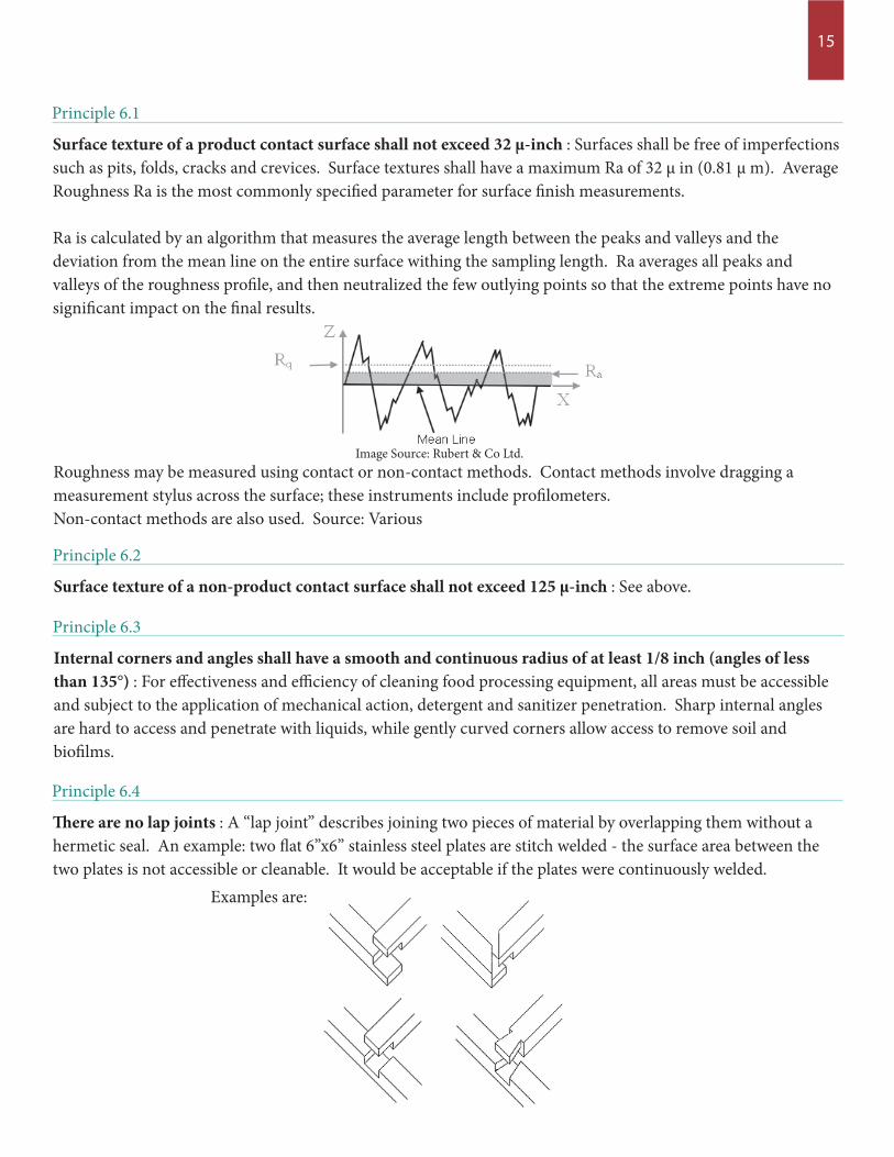
Surface texture of a product contact surface shall not exceed 32 µ-inch : Surfaces shall be free of imperfections such as pits, folds, cracks and crevices. Surface textures shall have a maximum Ra of 32 µ in (0.81 µ m). Average Roughness Ra is the most commonly specified parameter for surface finish measurements. Ra is calculated by an algorithm that measures the average length between the peaks and valleys and the deviation from the mean line on the entire surface withing the sampling length. Ra averages all peaks and valleys of the roughness profile, and then neutralized the few outlying points so that the extreme points have no significant impact on the final results.
Principle 6.1
Roughness may be measured using contact or non-contact methods. Contact methods involve dragging a measurement stylus across the surface; these instruments include profilometers. Non-contact methods are also used. Source: Various
Surface texture of a non-product contact surface shall not exceed 125 µ-inch : See above.
Principle 6.2
Internal corners and angles shall have a smooth and continuous radius of at least 1/8 inch (angles of less than 135°) : For effectiveness and efficiency of cleaning food processing equipment, all areas must be accessible and subject to the application of mechanical action, detergent and sanitizer penetration. Sharp internal angles are hard to access and penetrate with liquids, while gently curved corners allow access to remove soil and biofilms.
Principle 6.3
There are no lap joints : A “lap joint” describes joining two pieces of material by overlapping them without a hermetic seal. An example: two flat 6”x6” stainless steel plates are stitch welded - the surface area between the two plates is not accessible or cleanable. It would be acceptable if the plates were continuously welded. Examples are:
Principle 6.4
Image Source: Rubert & Co Ltd.
16
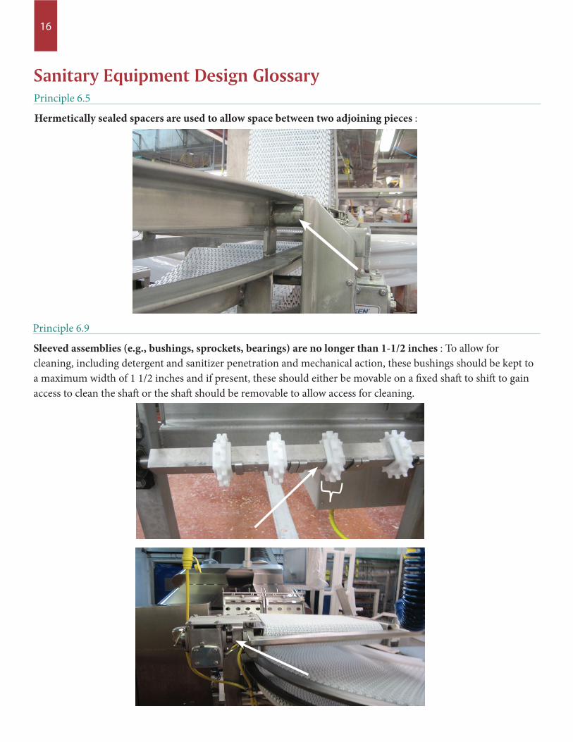
Hermetically sealed spacers are used to allow space between two adjoining pieces :
Principle 6.5
Sanitary Equipment Design Glossary
Sleeved assemblies (e.g., bushings, sprockets, bearings) are no longer than 1-1/2 inches : To allow for cleaning, including detergent and sanitizer penetration and mechanical action, these bushings should be kept to a maximum width of 1 1/2 inches and if present, these should either be movable on a fixed shaft to shift to gain access to clean the shaft or the shaft should be removable to allow access for cleaning.
Principle 6.9
17
Press and shrink fits are not used : These are not permitted for use as they do not allow for movement and associated cleaning and penetration of detergents, mechanical action or sanitizers.
Principle 6.10
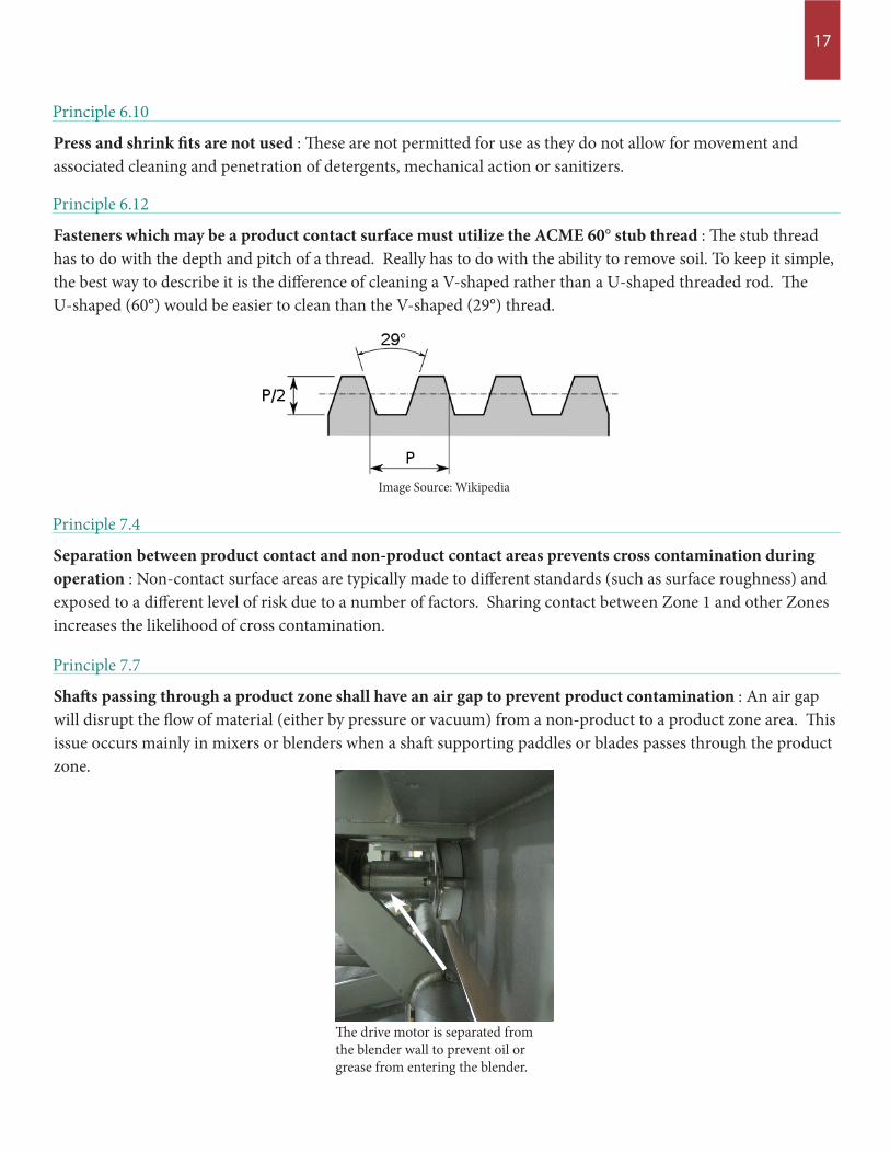
Fasteners which may be a product contact surface must utilize the ACME 60° stub thread : The stub thread has to do with the depth and pitch of a thread. Really has to do with the ability to remove soil. To keep it simple, the best way to describe it is the difference of cleaning a V-shaped rather than a U-shaped threaded rod. The U-shaped (60°) would be easier to clean than the V-shaped (29°) thread.
Principle 6.12
Image Source: Wikipedia
Separation between product contact and non-product contact areas prevents cross contamination during operation : Non-contact surface areas are typically made to different standards (such as surface roughness) and exposed to a different level of risk due to a number of factors. Sharing contact between Zone 1 and other Zones increases the likelihood of cross contamination.
Principle 7.4
Shafts passing through a product zone shall have an air gap to prevent product contamination : An air gap will disrupt the flow of material (either by pressure or vacuum) from a non-product to a product zone area. This issue occurs mainly in mixers or blenders when a shaft supporting paddles or blades passes through the product zone.
Principle 7.7
The drive motor is separated from the blender wall to prevent oil or grease from entering the blender.

1150 Connecticut Ave., NW | 12th Floor Washington, DC 20036
www.meatpoultryfoundation.org
F O U N D AT I O N F O R
R E S E A R C H E D U C A T I O NM E AT P O U LT R Y