sapip-irt instruction manual - dynamaxdynamax.com/images/uploads/papers/irt_manual.pdf · version...
TRANSCRIPT

SapIP-IRT
Dynamax, Inc
SapIP-IRT Instruction Manual
This manual provides Dynamax customers with a detailed collection of instructions on
How to set-up, collect data and make full application of the SapIP-IRT sensor.
Created: 12/14/2017
Version 8.4 8.4 – Changes from 8.3: Added quick start guide 1.3, pg 15. Drip loop on power wire Sec 4, pg 22. Changed wiring for SDI-12, better cable and color code Sec 4.3, pg 24.

SapIP – IRT Instruction Manual 1/23/2017
Page 1 Dynamax, Inc.
Table of Contents
Topic I. Introduction II. General Specifications III.
Assembly and Mounting Procedures
IV.
Sequential and Functional Descriptions
V. Updating Logging Interval Using XCTU
VI.
FAQs – Frequently Asked Questions
VII.
Troubleshooting
VIII.
Appendix A: Data Output Packets

SapIP – IRT Instruction Manual 1/23/2017
Page 2 Dynamax, Inc.
I. Introduction The new SapIP-IRT wireless infrared temperature system is the latest development in infrared
leaf temperature sensing technology for applications in irrigation scheduling and plant stress detection. As a temperature sensor, the module has many other applications and can be considered a general purpose temperature sensor.
The newest IRT( Infra-Red Temperature) module has a narrow field of aperture and has an
imbedded processor temperature controller for a calibrated digital signal. The imbedded processor provides a comparison to the reference body temperature and makes a series of readings to generate one value. This module has a very accurate reading to +/- 0.5 C, is very stable over time, and has a signal window and field of view (FOV) For example; at a 20 degrees FOV one would have a complete coverage of 95%. So, for a 1 meter wide target, a customer would have to place his or her IRT 3 meters above the item or surface being measured (20 degrees FOV).
This new system allows small IRT nodes to be distributed throughout a field, and for its recorded
data to be collected with a coordinator module then stored in a logger or transmitted to a display or controller.
There are several means of collecting the IRT’s temperature node data: communicating in a
public ZIGBEE data network, or with a serial port or by analog voltage signals. There are three versions: SAPIP-IRT Zigbee Node
Digital Data Stream
Wireless Transmission to Zigbee coordinators
SAPIP-IRT-AD
Analog Module – Volts Output
Wired connect to SAPIP-RS9, or SAPIP-RS24 Or any analog logger.
SAPIP-IRT-SD
Serial 3 wire Digital Data Stream
Wired transmission to loggers and SDI-12 field bus. (New product 4 Q 2016)
The following items support the ZigBee wireless version: SAPIP-IRT-COR Coordinator
module Central termination for ZigBee, collects data and transfers to a USB port
SAPIP-REP24-ZB Router module Repeater/Router to extend range of ZigBee networks
SPIP-IRT-WS Software application
Simple data collection program using the coordinator module

SapIP – IRT Instruction Manual 1/23/2017
Page 3 Dynamax, Inc.
Once it is transmitted the data can be calculated, displayed, and graphed on Dynamax’s customer website named Agrisensors.net. This network will consist of the customer’s SapIP network, along with the units accompanying temperature (analog) sensors.
The client also has the option to download his or her data files to a PC or an imbedded SCADA
controller. PC data collection is supported with the purchase of a coordinator module (SAPIP-IRT-COR ) and a windows software collection program, the IRT Watcher, (SPIP-IRT-WS). These data sets can be imbedded into SCADA or independent controllers to calculate plant stress models which can determine when and how often the client’s crops need irrigation. Dynamax does not plan to provide SCADA controllers, but does provide stress monitoring hardware and a WIFI broadcast manager, the SPIP-SALH – The Stress Accumulator Logger.
Further, the SapIP-IRT leaf temperature sensors can integrate as a complete stand-alone system
or as part of a SapIP wireless mesh network. The complete network contains an option for plant sap flow, sap velocity, soil moisture, weather, and leaf temperature, all which can be monitored simultaneously all in one system. Up to 40 SapIP-IRT nodes can be connected wirelessly with a single GSM modem and the nodes can be “daisy-chained” up to four levels deep, which can allow data to be transmitted from distances over a mile away.
Lastly, these SapIP systems are both versatile and flexible allowing them to be applied for
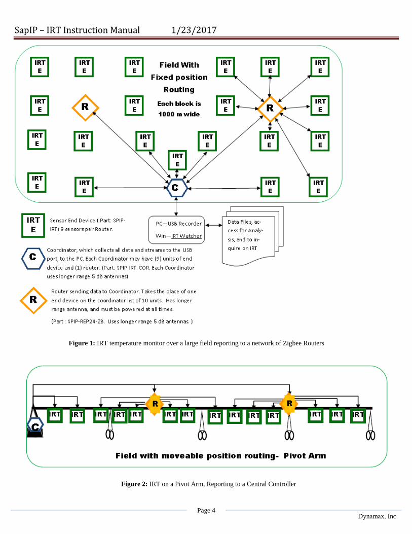
several different purposes.. Each unit is configurable for a customer’s specific applications, and records surface temperature from 0-50 C. The sensor operates over a long distance via the relay and coordinator network covering a very large field as shown in the chart Figure 1. The IRT may be arranged in a pivot system, where the data is transmitted to a central pivot controller (Figure 2). The structure of the IRT network is a mesh network so nodes can relay data from the End node to a Coordinator node. Each Coordinator node is the collection point for all data, and therefore is the concentrator for all data coming to the system. Each Router has a limit of 10 Zigbee nodes. Each Router reports its data to the Coordinator, which dumps its data into the IRT Watcher, the Windows program that creates and saves data to a PC. Each node arranges communication links upon power-up finding the shortest path to the Coordinator node.
SapIP – IRT Instruction Manual 1/23/2017
Page 4 Dynamax, Inc.
Figure 1: IRT temperature monitor over a large field reporting to a network of Zigbee Routers
Figure 2: IRT on a Pivot Arm, Reporting to a Central Controller

SapIP – IRT Instruction Manual 1/23/2017
Page 5 Dynamax, Inc.

SapIP – IRT Instruction Manual 1/23/2017
Page 6 Dynamax, Inc.

SapIP – IRT Instruction Manual 1/23/2017
Page 7 Dynamax, Inc.
II. General Specifications
1. Infrared Temperature Sensor Specifications
1.1 Purpose - The imbedded infrared temperature sensor reads an object’s temperature as well as its own
body temperature and compensates for the body temperature.
1.2 Specifications - Industrial/commercial accuracy: +/- 0.5 ˚C (0-50 degrees C). - Each unit is factory calibrated and very stable over time. (Ref USDA internal report) - Narrow field view:
o 10 Degrees (50% sensitivity) (5.6:1 View Dist:Width) o 15 Degrees for 80% sensitivity
i.e. at 15 degrees 80 % of the temp signal is included in view. (4:1 View Dist:Width)
o 20 Degrees for 95% sensitivity i.e. at 20 degrees 95% of the temp signal is included in view. (3:1 View Dist:Width)
2. Data
2.1 Purpose - The purpose of the SapIP-IRT’s data collection is to provide the user with real time data
measurements. Typically the sensor will take 2 seconds to read the temp, and then the results are either averaged or saved according to the collection steps.
- - Each set of data can be displayed in a digital format for when it is accessed wirelessly and
presented remotely in graphical format for crop temperature and stress analysis. - - Analog data will be converted to digital data and presented in crop temperature and stress
analysis calculations. Since analog data is converted from digital and then converted back to digital, it is inherently less accurate than digital and yet is very similar to non-IR rated temperature sensors.

SapIP – IRT Instruction Manual 1/23/2017
Page 8 Dynamax, Inc.
2.2 SAPIP-IRT Specifications
2.2.1 Data Collection – RF Network - Samples are taken continuously every 10 seconds, accumulated and then averaged. This
average value is then sent by radio at 1, 5, 10, 15, 30 or 60 minute intervals. The averaging accumulator is then reset.
- Settings are defined upon order from Dynamax. These settings are normally set in the factory, but are changeable in the field using the IRT watcher program. Protocol:
- Open Protocol: Data can be encrypted, coded, and read by any manufactured Zigbee device or gateway.
- The Dynamax preferred network is the Digi International Zigbee network. - - Adjacent Zigbee networks have settings for their respective network ID’s to discriminate
different signals. o Notes on Open: We have found that a variety of manufacturers have implemented
the “open” Zigbee protocol, however that does not mean that each will find the specific node you may purchase without programming. For example a Texas Instruments (TI) Zigbee may be quite difficult to program to talk to a Digi device, since the TI device may need a significant development tool to program it to accept a setting we have chosen for the Digi Device.
- In our Zigbee Format: We have chosen the Digi International since the tools, and supporting coordinator hardware is complete and fully supported with Windows software tools. Settings for the groups of agricultural networks that are close together requiring Pan and in some cases channel assignments to avoid interruption. Our application engineers and technicians are very familiar and can program your network to satisfy any requirement.
2.2.2 Output - Sensor output is a packet transmission which contains a time tick, serial number, battery
voltage target IR temperature (+/- 0.01 degrees Celsius resolution), and sensor body temperature. Each item is separated by a comma and the last character is a carriage return. i.e. “1, 17, 5.1, +32.70, +24.80/cr”
2.3 SAPIP-IRT-AD analog specifications
2.3.1 Data Collection Analog output - Samples are taken continuously every 10 seconds, accumulated then averaged. This
average value is then updated on the analog output port at 1, 5, 10, 15, 30 or 60 minute intervals. The averaging accumulator is then reset.
- Settings are defined upon order from Dynamax. These settings are normally set in the factory, but are changeable in the field using the IRT watcher program.

SapIP – IRT Instruction Manual 1/23/2017
Page 9 Dynamax, Inc.
2.3.2 Analog Output Specification A low impedance voltage scaled to represent temperature is available on the connection wiring harness. In the equation below, Vo is that output voltage which corresponds to T the target object temperature.
T = Vo/0.01 - 40.0 (T is in degrees C).
Voltage Range 0 – 1.6 V
2.4 SAPIP_IRT-SDI serial digital specifications The SDI version is a passive client, no actions are performed automatically. Commands and data are transmitted through a bi-directional serial port. The port follows the standard “SDI-12 A Serial-Digital Interface Standard For Microprocessor-Based Sensors Version 1.3”. Digital signals are on the wiring harness.
2.4.1 Data Collection Measurement collection is triggered by an “aM” or “aMC” command. The “a” is the unit address, the “C” calls for a checksum. The measurement takes 2 seconds.
2.4.2 Serial Data Output The data is held in memory and transmitted on the port after receipt of a “xD0” command. The response will be the Sensor ID, then battery voltage, and then object temperature followed by the ambient temperature in one line, terminated with a carriage return/linefeed. For example: “1+0036+6.0+22.04+21.34(CRLF)”. For the checksum version a three character checksum comes before the CRLF.
3. Radio Mesh – Wireless Network to Controller, and Network to Cloud Option
3.1 Purpose - The purpose of the Zigbee protocol is to have a method of connecting the data results from
nodes to a coordinator. The coordinator then concentrates all the data for the industrial controller, or PC to analyze the data. Users or the central controller make irrigation decisions based on the information recorded.
3.2 Specifications - Zigbee Protocol: Ultra-modern, self-healing mesh networking. Contains assignable network
PAN ID’s for comingled networks. Nodes are automatically discovered and assigned a data destination to the coordinator of the network. The Routers collect data from End nodes and transmit to the Coordinators assigned to a network.
3.3 Digimesh Range (SapIP-IRT-DM Network) - 900 MHz Range (To be announced in 2016): 6500 feet (2 kilometers).
o This new Node will have the advanced Digimesh network built –in and extends the range to 4-5x of the Zigbee. The node will have the radio transmit to a gateway protocol that will extend the data to the Agrisensors.net cloud based monitoring service. Note: 2 kilometer (1 to 2 miles) These ranges only apply when there is a direct
line of sight (LOS) which is not obstructed and the antenna is correctly

SapIP – IRT Instruction Manual 1/23/2017
Page 10 Dynamax, Inc.
aligned. Note that a high gain antenna requires alignment vertically, so that a very narrow horizontal aperture lines up with the target antenna.
3.4 Digimesh Range with Analog Signal SapIP-IRT-AD (SapIP- Agrisensors Network) 3.4.1 With the Digimesh SapIP-Network, one may attach 6 IRT-AD sensors to one network
node. 3.4.2 Each analog signal node is converted to digital, transmitted, and individually
converted to temperature at the Agrisensor.net customer Ranch Page. 3.4.3 Canopy temperatures may also be converted to Growing degree days, Crop Water
Stress Index (CWSI) , or to Degrees Above Non Stressed Plants (DANS). CWSI requires a SapIP weather node. The canopy temperature and tree trunk is converted to chill hours and are best used for freeze warnings.
4. Antenna Range
4.1 Zigbee Specifications 2.4 GHz Range. Dynamax uses a high power 2.4 transmitter. 4.1.1 Range 1600 feet (500 meters): 5 to 7 dBi antenna omnidirectional - (high gain). High
gain antennas are included with coordinators and Routers. Each high gain antenna is sealed form water and is more sensitive when it’s raining. Part Number kit is SPIP-ACC24-EW.
4.1.2 Range 300-500 ft ( 100-150 meters): 7 dbi antenna omnidirectional – with spark gap
protection, and grounding. Part no is SPIP-ACC24, and is an exposed antenna.
4.1.3 Range 150 feet (50 meters): 1 to 1.5 dBi antenna omnidirectional - (low gain, rubber duck style). Sealed water-proof rubber duck are supplied by Dynamax (Most Wi-Fi antennas are not water proof). Part no is SPIP-IRTANT24.
4.1.4 Range over 500 meters: Dynamax supplies directional antennas, which can extend
range 3-4x.
4.1.5 All Ranges are in clear air - line of sight (LOS). With vegetation, the signal should be 1-2 meters above the canopy (3-6 ft). Rain and wet canopy absorb 2.4 Ghz signals, and the signal is absorbed on a wet antenna. For increased LOS range use the DigiMesh 900 Mhz. See Section 3.3 or 3.4 for high range.
5. Power SAPIP-IRT-ZB Battery and Solar Panel
5.1 Battery Specifications – Rechargeable 4 NIMH batteries included. Typical current 2000 mAh, 4.8 V. (Typical battery pack is 4.8 V nominal, 5.2 V operational charged) Maximum battery voltage – 6.2 V during charging Minimum battery operations – 4.2 V Operational measurements and response suspended at below 3.8V,

SapIP – IRT Instruction Manual 1/23/2017
Page 11 Dynamax, Inc.
Until minimum voltage is restored (4.2 V). Only battery recharge will occur below 3.8 V.
5.2 Solar panel or DC adapter for recharge. DC Adapter – requires 100 mA at 12 V. Top-off mode requires 230mA at 12 volt. Solar 2 W (150 mA) to 5 Watt solar panel. (Most 5 W solar panels are less expensive.)
Low charge rates to minimize battery temperature. 40 mA charge current (12V), to restore batteries from a 12 V solar panel.
Top off charge is also controlled (see from external commands in ‘IRT Watcher’). 230 mA current (12 V), allowed to charge batteries 5 hours internally, or temperature rise of the battery, or up to 6.2 V whichever occurs first. Reverts to low charge rate after above.
Notes: Any reverse voltages, over voltages and/or voltage spikes are protected at inputs with resettable fuses. The IRT battery should not be discharged.
Batteries should be charged before storing. Batteries should be disconnected before storing.
6 Power SPIP-IRT-AD Analog Version Specifications – No batteries included. Logger provides power: DC from either 5 V or 12 V supply to the IRT. Logger typically switches on IRT for 2 seconds, takes a reading then stores the results. After, the logger will power down the IRT. Minimum 5 V input (this is considered typical operation).
Current 6 mA average, maximum 25 mA during readings. Maximum 12-18 V – voltage or switched supply at 12 V battery nominal.
Current 3 mA average, maximum 12 mA.
7 Power SPIP-IRT-SDI SDI 12 Digital version Specifications No batteries included. Logger typically switches on IRT for 2 seconds, then initiates a sequence to alert the IRT to wake up, then command it to send the serial SDI-12 data, and stores results. Afterward, the logger has the ability to power down the IRT if it chooses. Maximum 12-18 V – voltage or switched supply at 12 V battery nominal.
Current 4.5 mA minimum, maximum 5.8 mA during readings.
Input Volts Current (Avg.) 12.0 V Standard SDI-12 4.6 mA 6.0 V 4.6 mA 5.5 V – Minimum Operation 6.0 mA

SapIP – IRT Instruction Manual 1/23/2017
Page 12 Dynamax, Inc.
#1
#2
8. Enclosure
8.1 Specifications Completely sealed off field enclosure. Sealed to IP67, waterproof, rain proof, and weather tightened. Mounting options include a low-cost 2” EPS conduit hanger Optional gimbal mounted into a threaded socket (1/4” camera).
III. Assembly and Mounting Procedures - Each SapIP-IRT should be assembled and installed following the protocol found in the following
sections. This will ensure no problems will arise during each unit’s tenure in the field. A collection of four separate mounting procedures have been collected and illustrated below.
o Several tools will be required during installation. A general set that will be needed are
found here: Flat-head Screwdriver, (5/64”) Philips-head Screwdriver Crescent Wrench or set of Pliers Drill /Drill-bit (5/16”)
1. Dynamax Mounting Kits - The Dynamax Mounting Kit and the Adjustable Mounting Kit are the overall preferred method of
installing each SapIP-IRT unit. Each set of equipment and the procedures for its installation are described within its associated sub-section(s) below. For lower canopy crop such as cotton or wheat, a fixed height (3 ft) above ground are recommended.
Materials - When purchased, both the SapIP-IRT and Adjustable Mounting Kit come with the materials
necessary for proper installation. Each accessory needed during the installation process is included.
1.1 Dynamax SapIP-IRT Fixed - Dynamax SapIP-IRT - Each device ordered comes with the 2” EPS conduit hanger
(shown below) to fasten the unit to the mounting kit.
Included are - ¼ ” x 1-1/2” Hex-Head Bolt SS, nut and washer - 5/16 ” x 3” Hex head Bolt, Galv, Nut, and Washer - Zip-ties (customer provided - optional)
o Can be used to fasten any loose cables to the sensor cross-arm.
1.1.1 Install the EPS hanger on a vertical pole that has been pre-drilled with a 5/16” (8mm) hole at the top of a conduit (1.25” diameter) or a horizontal hurricane fence pipe (1.25” diameter).

SapIP – IRT Instruction Manual 1/23/2017
Page 13 Dynamax, Inc.
#2
#1
1.1.2 Insert the 5/16 x3 bolt and washer through the EPS hanger hole and affix to the vertical pipe as shown in #1. Tighten the lock washer and the nut to hold the IRT in a 45 degree tilt to the canopy being monitored.
1.1.3 Insert SapIP in the hanger bracket, and insert the ¼ x 1-1/2 Hex Bolt at position #2. Position the IRT and clamp the hanger so that it is balanced, and add the lock washer and nut and tighten.
1.1.4 The pole can be inserted into the ground or onto a barbed wire post or fence post for both fixed and adjustable height. See Section 2 and 3 of the installation instruction.
1.2 Dynamax Adjustable Mounting Kit - CM204-D ( See Fig 1 ) o Stainless steel sensor cross-arm o Mounting plate o Required fixtures
- User provides a 4 ft. Vertical Pipe (1”), and a
reducer 2”-1” and a 2” pipe to install into the ground. (See #2)
1.2.1 Installation - The next section illustrates the procedures
Dynamax recommends when installing the adjustable mounting kit and how to correctly fasten the SapIP-IRT to the unit.
1.2.2 Assembling the Mounting Kit - The first objective is to correctly attach the 4 ft. vertical pipe to the mounting plate. To
begin, one will need to determine where he or she wishes to place the mounting plate.
- Next, press the plate at the pre-
determined location and locate the U-shaped bolts and their associated screws (illustrated in red,(#1) below). The plate should fit securely within the vertical groove or tract (illustrated in black, (#2) below).
-
o Note: This unit will come with 4 total U-bolts which will fit around each pipe, either vertically OR horizontally.
#1

SapIP – IRT Instruction Manual 1/23/2017
Page 14 Dynamax, Inc.
- Place the U-bolts around the pipe and
through the holes of the plate. This attachment should fit very securely.
- Place a washer on each side of both bolts.
Screw the nuts tightly on top of the washers on each side of both bolts, until the plate is firmly fastened to the plate. Make sure each U-bolt’s evenly fastens the pipe in place.
o Note: The vertical groove that the pipe fits in should keep the plate and 4 ft. pipe
firmly attached while in the field.
- One now needs to place the sensor cross-arm on the opposite side of the mounting plate (perpendicular to the vertical pipe). Begin by locating the last two U-bolts and their associated washers/nuts.
- Using the same process used to fasten the vertical pipe,
start by placing a washer on each side of both bolts. Screw the nuts tightly on top of the washers on each side of both bolts, until the plate is firmly fastened to the plate. Make sure each U-bolts evenly fasten the pipe in place.
- The final mounting kit should look
somewhat identical to figure 5, illustrated below:
1.2.3 Mounting the SapIP-IRT - The first objective towards correctly
fastening the SapIP-IRT to the adjustable mounting kit is to locate a place on the pipe where one wishes to mount the IRT.
- If not done so already, one will need to
drill a hole through the pipe center using a 5/16” drill bit. Position the sensor 1 to 2 m above canopy. Drill more holes higher if the canopy will grow higher.
- After this is complete, take a hex-bolt from the parts and place a washer on it.
#2

SapIP – IRT Instruction Manual 1/23/2017
Page 15 Dynamax, Inc.
- Slide hex-head bolt is tthrough the sensor conduit hanger. Grab the 2” EPS conduit hanger and place it on the pole, insert the bolt, with the opening facing downward.
- Affix a hex-head nut on top of a washer.
- Place the IRT through the hanger and screw
together the last horizontal bolt found on the bottom of the conduit, which will grasp the IRT. This will keep it firmly in place throughout the duration it is in the field. An illustration of the last bolt that will need to be fastened is shown below as a red arrow. 1.3 QUICK START GUIDE
1.3 QUICK START GUIDE Overall Installation – sequence of operations for linking up Zigbee RF modules After installing the sensors, from either Section 1.1 to 1.2, or by installing to a fence post in 2.1 to 2.3, here are the sequences to follow to have communications start up the first time. (Powering up the IRT in Section 4). 1.3.1 – First install the Coordinator, the receiving device, and make sure that it is powered up. If you are using a Coordinator inside the SALH, make sure that the device is on, and has been reset. Both the coordinator and the SALH have coordinator chips which are programmed by Dynamax to a specific Channel and Specific list of PAN ID, and all the IRT have been programmed to respond to the coordinator address. Please make sure that the PAN ID and the SC Channels match. The Coordinator should have high gain antenna, and it should be waterproof, and should be powered on 100 % of the time. If AC power is applied thru a converter, get rid of that, and use a 120 V charger and a battery with 4 Ahr supply at 12 V to make sure it is always on. 1.3.2 Then power up the Routers. The Routers should have high gain antenna, and antenna should be waterproof, and should be powered on 100 % of the time. If AC power is applied thru a converter, get rid of that, and use a 120 V charger and a battery with 4 Ahr supply at 12 V to make sure it is always on. One may use a solar panel as well with a 4 Ahr sealed (4x5 x 6 “ size). After powering up the Routers, you may use a XBIB Zigbee module in the coordinators to scan the channels with the XCTU Configuration and Test software, to make sure all Routers are on, and what the signal strengths are. The appendix shows some of the operations of the XCTU module. 1.3.3 Finally Power up the End Nodes (Section 4) Each path of the Zigbee protocol establishes a route to the coordinator, and keeps that route until there is a network reset, or the node is turned off. Thus is required that the Routers and the Coordinator are powered on, to settle the connection and transmit data. We recommend that the closest nodes to the coordinator are turned on first.

SapIP – IRT Instruction Manual 1/23/2017
Page 16 Dynamax, Inc.
2. Hurricane Pole Attached to Fence Post - The second method of successfully installing a SapIP-IRT unit in the field is by mounting the
sensor on a hurricane pole that is vertical or attached to a fence post. Each set of equipment and the procedure(s) for its installation are described within its associated sub-section below.
2.1 Materials - When purchased, the SapIP-IRT comes with all the materials that will be required to mount it
on a medium within the field. For this instance, the customer will need to have a stable fence post firmly set in the ground with the ability for a vertical pole to be fastened to it. The IRT will be mounted to the top of this pole where it will take its measurements. Each accessory that is needed during the installation process can be found below.
2.1.1 Dynamax SapIP-IRT - Dynamax SapIP-IRT - 2” EPS conduit hanger (shown below) which will be needed in order to fasten the unit
to the mount pole.
- ¼ x 1 - 1/2” Hex-Head Bolt SS ; ¼- Hex-Nut SS; ¼ USS Flat Washer SS - 5/16 x 3” Hex head Bolt Galv.; 5/16 Hex nut Galv; 5/16 Flat Washer - Zip-ties (optional) o Can be used to fasten any loose cables to the sensor cross-arm.
2.1.2 High-Gain Antenna Kit - The high-gain antenna kit is used for applications where long-distance transmission is
required. o Note: If the client has purchased a low-gain antenna, refer to its specific installation
technique found within the section above.
- Each material found in the High-Gain Antenna Kit can be found on the quote provided by Dynamax during the time of purchase. An illustration of each piece of equipment is provided below.

SapIP – IRT Instruction Manual 1/23/2017
Page 17 Dynamax, Inc.
2.1.3 Hurricane Pole - A hurricane top rail pipe is the easiest mounting option, items which will be provided
by the customer.
- Since the IRT comes with the necessary materials to mount it on a medium these bolts require that it be mounted on a vertical pole a minimum of 1” in diameter (25 mm) (Dynamax suggests a stainless steel 1 – 1/4” hurricane fence top rail pipe as shown in the attached drawings).
- A 5/16” sized drill bit will need to be used to create a place on the cross arm where a
hex-head bolt, washer, and nut can mount the IRT. o Note: Be sure to allow 3-4” inches from the end of the pipe so one has room to
clamp the antenna’s hanger.
2.1.4 Fence Post - The next part of this assembly, a barbed wire fence post is provided by the customer. - Prepare the fence post by drilling a hole through the pipe (vertically) using a 5/16”
(8mm) drill bit. - Be certain that the fence post is secure within the ground and provides a means that
will allow it to fasten to the vertical cross-arm.
2.2 Installation - Installing the SapIP-IRT should begin with having a pre-existing fence post already firmly
planted in the ground.
- The customer must next securely fasten the hurricane pole to the fence post. It is up to the client in regards to how this is achieved; however, the connection will need to be firm enough to hold the pole securely in place for the duration of time it is in the field. An example of the finished pole and fence post attachment can be observed below.

SapIP – IRT Instruction Manual 1/23/2017
Page 18 Dynamax, Inc.
- Lastly, the assembly and mounting procedures can begin for the high gain antenna and the
IRT.
2.2.1 Mounting the SapIP-IRT - The first objective towards correctly fastening the SapIP-IRT to the vertical pole is to
locate a place on the pipe where one wishes to mount the IRT. o Note: Be sure to allow 3-4” inches from the end of the pipe so one has room to
clamp the IRT 2” EPS conduit hanger.
- If not done so already, one will need to drill a hole through the pipe (vertically) using a 5/16” (8mm) drill bit.
- After this is complete, one can grab a 5/16” hex-bolt from the mentioned set of IRT
materials and slide a washer on it. Grab the 2” EPS conduit hanger and place it with the opening facing downward. The top of the hanger has a place one can slide the bolt through.
- Place it through the sensor cross arm or the vertical pole. Screw in a hex-head nut on top
of a washer.
- Place the IRT through the hanger and insert the ¼ x 1-1/2” bolt to close the hanger, which will grasp the IRT. This will keep it firmly in place throughout the duration it is in the field. An ¼ x 1-1/2 bolt will need to be fastened within the hole at the red arrow.
We recommend the pole is fastened to the fence post with hex bolt, lock washers and nut as shown. Drill additional 5/16” holes in the pipe to extend the pole higher if the crop may be expected to grow. Additional 5/16” bolt and nuts will be supplied by customer

SapIP – IRT Instruction Manual 1/23/2017
Page 19 Dynamax, Inc.
2.2.2 Connecting the High-Gain Antenna - To begin this process, must find the item marked #1 as denoted in figure 3. Place this
small version of hinge hanger at the end of the pole and grab the lock washer associated with it. Slide the hex-head bolt through either side followed by a washer and hex-nut to firmly lock it in place.
- Next, select the RSMA antenna connector, marked as #3 within figure 3. This item should be screwed on the golden apparatus on the far end of the IRT. After turning closed your fingers, then screw it in place tightening with a small crescent wrench 1/8 of a turn. This will properly seal the silicon inside the water seal of the connector.
- Next, #4 and #6 will bolt together through the hanger hole on #1. One will need to find the washer which fits around #6. This will allow both #4 and #6 to firmly screw and hold itself together on #1. The customer will need to use a crescent wrench at the bottom, and pliers to screw the top together so the pieces are tight enough, and the antenna seal is secure from water.

SapIP – IRT Instruction Manual 1/23/2017
Page 20 Dynamax, Inc.
3. Chicken Wire Fence Post - The alternative method of installing the SapIP-IRT is by mounting the sensor aboard a
chicken wire fence post. This section will briefly describe the techniques required to correctly mount the IRT using this method. Each set of equipment and the procedure for its installation are described within its associated section below.
3.1 Materials - When purchased, the SapIP-IRT comes with all the materials that will be required to
mount it on a medium within the field. For this instance, the customer will need to have a stable chicken wire fence post where the IRT can be mounted. Each accessory that is needed during the installation process can be found below.
3.1.1 Dynamax SapIP-IRT - SapIP-IRT - 2” EPS conduit hanger (shown below) which will be needed in order to be fastened
the unit to the mounting kit.
- ¼ x 1 - 1/2” Hex-head Bolt SS ; ¼- Hex-Nut SS; ¼ USS Flat Washer SS - 5/16 x 3 “ Hex-head Bolt Galv.; 5/16 Hex nut Galv.; 5/16 Flat Washer - Zip-ties (optional)
o Can be used to fasten any loose cables to vertical pole.
3.1.2 Chicken Wire Fence Post - A fence post will be the only material that the customer will need to provide during
installation.
- Prepare the fence post by drilling a hole through the post using a 5/16” drill bit. An example of the drilled hole is illustrated by the red arrow below:
- Be certain that the fence post is securely inserted into the
ground.
3.2 Installation - Installing the SapIP-IRT should begin with having a pre-existing
fence post already firmly planted in the ground.
- The customer must install the 2” EPS conduit hanger to the top of the fence post.
SapIP – IRT Instruction Manual 1/23/2017
Page 21 Dynamax, Inc.
3.2.1 Mounting the SapIP-IRT
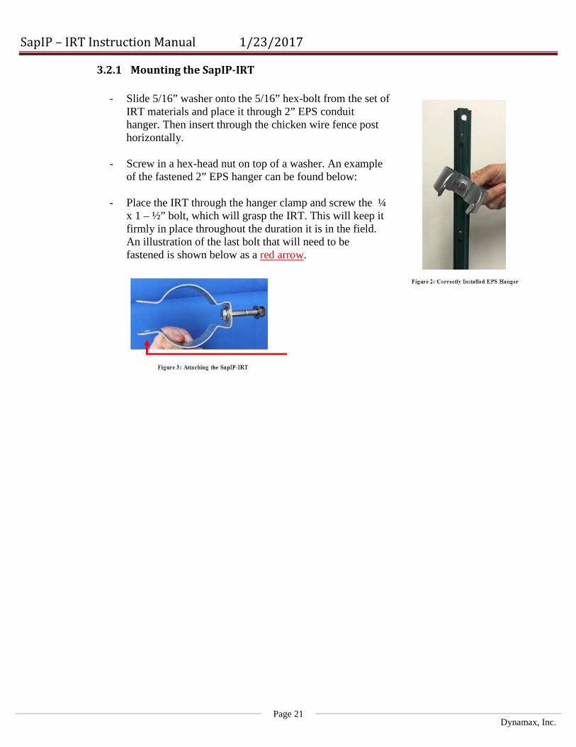
- Slide 5/16” washer onto the 5/16” hex-bolt from the set of IRT materials and place it through 2” EPS conduit hanger. Then insert through the chicken wire fence post horizontally.
- Screw in a hex-head nut on top of a washer. An example
of the fastened 2” EPS hanger can be found below:
- Place the IRT through the hanger clamp and screw the ¼ x 1 – ½” bolt, which will grasp the IRT. This will keep it firmly in place throughout the duration it is in the field. An illustration of the last bolt that will need to be fastened is shown below as a red arrow.

SapIP – IRT Instruction Manual 1/23/2017
Page 22 Dynamax, Inc.
4. Power and Attaching the SapIP-IRT - This section pertains to each of the three subsections above, and describes the basic attachment
of the cables and power up procedures of the SapIP-IRT. - Begin by attaching the charging cables ( note: each has a male connection on the SapIP-IRT): - First attach the (-) side of the solar panel to the black lead of the SapIP-IRT solar input (-). - Then attach the (+) side of the solar panel to the red lead of the SapIP-IRT input (+).
Warning: The last 6 inches of the solar input and battery wire should be coiled into a loop so that a drop of water entering the cable will not travel into the SAPIP-IRT. The drip loop should be affixed with zip ties below the SapIP-IRT. We recommend that silicone glue is squeezed into the jacket between the red/black wires.(10/14/2017 ECN) Note: If one has zip-ties, wrapping them at various locations around the sensor cross-arm will prevent any cable or wire slack while in the field.
- Locate the golden male connection end at the top of the
SapIP-IRT and screw on the antenna. Apply some silicone grease to the male threads to secure water tightness. An illustration below provides an idea of where the fixture is that the antenna will be screwed onto. See figure 7.
- Now the customer is ready to power on the IRT. First, identify the two wires pertruding from the bottom of the unit (illustrated by the red arrow in figure 8) and the small white terminals connected to the end of one wire (illustrated by the black arrow in figure 8). This white connector will be the on and off switch, which is a housing where one red wire will be screwed into.

SapIP – IRT Instruction Manual 1/23/2017
Page 23 Dynamax, Inc.
- Lastly, to power on the IRT one will need a very small flat-head screwdriver. Place the wire with the open lead end into the connector housing. Screw down the affixing screw and so the wire will be held firmly by the screw into the housing.
- This will cause a closed circuit to the battery and the IRT will power on. - Tuck the power switch housing into the cavity and secure with a putty to prevent ants from invading
your power switch housing. o Note: LEDs will blink if the unit is turned on, illustrated by the red arrow below. o The upper side next to the antenna is the Radio power LED. It initially blinks four times when in
contact with the coordinator. After normal operation, the transmit LED will blink briefly only once each minute. When transmitting the radio LED will blink on for 1/2 second.
o The lower side LED is the IRT processor and will blink every 10 seconds while taking readings. o The lower LED will also blink with signals to the user while transmitting.

SapIP – IRT Instruction Manual 1/23/2017
Page 24 Dynamax, Inc.
- One can observe a correctly installed IRT placed at the end of the sensor cross-arm, below:
4.2 Wiring the SAPIP_IRT_AD version
For the analog only version, use the same instructions above except to add wiring from the sensor to the logger. Please see the wiring diagram below. Wiring length is maximum 75 ft , AWG 22 minimum dia.: SapIP-
IRT Color Datalogger
Power+
RED Switched 12V
or 12VDC battery
Power- BLACK G Signal + WHITE 1H
Signal - GREEN 1L (-)
Shield CLEAR Shield - Drain
Note: using switched 12V, power has to be on for at least 2 seconds before reading sensors.
4.3 Wiring the SAPIP_IRT_SDI version For the serial SDI version there is no battery so the on/off switch is not used. The power and communications signals are in the cable bundle and must all be hooked to a suitable SDI capable logger. Please see wiring diagram, Wiring length is maximum 75 ft , AWG 22 minimum dia.: SapIP-
IRT Color Datalogger
Power+
RED Switched 12V
or 12VDC battery
Power- BLACK G OPEN CLEAR Shield – Drain or
(G) SDI BROWN/White SDI12 Data

SapIP – IRT Instruction Manual 1/23/2017
Page 25 Dynamax, Inc.
Signal
IV. Sequential and Functional Descriptions
1. Initialize - After resetting the hardware, all of the digital hardware is initialized to a known state that
will be ready for use.
1.1 Charge Battery Begins - First an EEPROM variable is monitored by the processor to indicate a thermistor is
embedded in the battery pack. When the command is given to top-off charge ( see 9.1 for IRT_ZB or 8 for IRT_SDI) the rapid high current charge sequence begins until termination. If the thermistor is not present then the unit will ignore temperature and stay in top-off mode until it reaches 6.2 V or charges for 5 hours (whichever occurs first). If the thermistor is present, termination can also occur if the battery exceeds maximum temperature, goes below minimum or the temperature rises too rapidly.
- All currents are set at 12 V input to the external battery charger circuit (solar panel input).
- The source of the units charge is from the solar panel (see specs).
- Charging is discontinued momentarily during the noise sensitive measurement cycle (2 seconds).
1.2 Check Battery Voltage - Battery voltage is checked to see if it is in the acceptable range. If the battery is below 3.8 V
a very slow LED blink will begin. The LED will be on for 10 milliseconds and off for 10 seconds and the charger will continue to function if it can.
- The IRT unit is frozen in this routine and will not change until the voltage rises over 4.2 volts.
1.3 Start Radio Link - Zigbee radio will then be turned on. The radio will attempt to join a network on PAN 100.
The radio is then put to sleep. o Note: Joining attempts will continue based on the unit’s profile settings.
- Radios are programmed for API mode. End device destination is set for 0= coordinator,
PAN=100, sleep mode=pin hibernate.
- Coordinator is set for PAN100, child poll timeout set to 30 minutes.

SapIP – IRT Instruction Manual 1/23/2017
Page 26 Dynamax, Inc.
2. Read Temperature - The Melaxis IR temperature sensor is read through an I2c two wire port. Six samples are
taken 10 seconds apart, averaged and stored in an accumulator (Note: 6 x 10 seconds = 1 minute.). If the EEPROM interval is set to zero, only one sample is taken.
3. Timing and Sleep Considerations - Sampling takes 2 seconds.
- The unit will sleep 8 seconds assuming the EEPROM ‘SERIAL_COMMAND MODE’ is off.
Otherwise, the unit will sleep for 1 second, then wakes up and turn on the radio for 30 milliseconds to check for any incoming commands. It will repeat this cycle 8 times, making a total of 10 seconds for sampling and sleeping
- Upon waking, the code will either receive another reading or send an output to the radio and
to the telemetry DC output. An EEPROM switch determines the number of minutes between outputs. The six samples taken 10 seconds apart are then averaged and added to an accumulator. These one minute readings are averaged in turn while waiting for the output timer. So, if the interval is 1 minute, each output is an average of 6 samples. If interval is 10 minutes then the output is an average of 60 samples, etc.
4. Format Data String - An EEPROM switch determines whether the radio is used. If it is not please skip to the
“Output DC Telemetry Signal” below. - The battery is checked exactly as it was in the initialization routine. If it fails, the program
halts (attempting to charge the battery) and the LEDs dimly blink (150 ms) every 10 seconds.
- Next, a data packet is constructed which contains the header information (see appendix), frame number, node ID, battery voltage, object temperature, sensor ambient temperature and the checksum. Each item is separated by a comma. i.e. “1, 17, 5.1, +32.70, +24.80/cr”
- Frame Number: A single digit which starts at 0 and increments during every output sample
(up to 9, restarting at 0). This number is also imbedded in the API header so that the ack/nack machinery knows which packet goes with each feedback packet.
- 4 Hex Digit / 32-bit Node ID: This is a hexadecimal ASCII string read out of the EEPROM.
The node ID identifies this particular sensor board in a network.
- Battery Voltage: Formatted as an xx.x string in volts. Maximum operational voltage is 18.0 V.
- Object Temperature: Formatted as a +/- xxx.xx string in degrees C. All data is averaged to
remove noise.
- Ambient Temperature: This is the sensor’s body temperature which is also formatted as a +/-xxx.xx string (degrees C).

SapIP – IRT Instruction Manual 1/23/2017
Page 27 Dynamax, Inc.
5. Radio to Coordinator - Before the packet transmission a delay is imposed which varies depending on the unit serial
number. o Note: Delay = serial No. Least Significant Byte x 10 ms. From to 0 to 150 ms.
- Next, the radio is then woken up from sleep mode and is followed by packet transmission.
Ack/nacks are then interpreted and is data re-transmitted if needed. - Radio is then put back to sleep. o Note: The delay previously mentioned is subtracted from 200 milliseconds and the
remainder is used for an additional delay. This makes the total delay exactly 200 milliseconds.
6. Output Analog DC Telemetry Signal - At the same timing interval as the radio outputs, an Analog DC (ADC) telemetry signal will
be updated. The conversion formula from the voltage output is: -
T = Vo/0.01 - 40.0 (T is in degrees C).
Voltage Range 0 – 1.6 V
- An EEPROM switch determines whether the ADC telemetry signal is used. If is not set, the
DAC is left asleep. The unit either does radio transmit and ADC, or just one output. - (Whichever combination is set by the two EEPROM variables: DAC_OUTPUT and
RADIO_OUTPUT).
7. Repeat sequence - Code jumps back to “Read Temperature” above. After the data is taken, formatted, and
transmitted.

SapIP – IRT Instruction Manual 1/23/2017
Page 28 Dynamax, Inc.
8. The SDI-12 Basic Command/Response Set “a” means the unit address
Name Command Response Break Continuous spacing for at
least 12 milliseconds None, sensor wakes up.
Acknowledge Active a! a<CR><LF>
Send Identification
aI! allccccccccmmmmmmvvvxxx...xx<CR><LF>
Change Address aAb! b<CR><LF>
Address Query ?! a<CR><LF>
Start Measurement * aM! atttn<CR><LF>
Ex: 2M!
Start Measurement with CRC
aMC! atttn<CR><LF> Example: 2MC!
Send Data aD0! a<values><CR><LF> or
a<values><CRC><CR><LF>
Example: 0D0!
Response:
0+39321+12.1+024.40+024.00

SapIP – IRT Instruction Manual 1/23/2017
Page 29 Dynamax, Inc.
Extended command F Fast Charge
aXF! Puts battery charge in top off mode
Extended command P Program eeprom
aXPsyyyySS S=#bytes to program, yyyy= address in EEPROM, SS is data( variable length )
Extended command X Read EEPROM
aXXsyyyy! S=#bytes to read, yyyy= address in EEPROM Response is immediate and is “aXXzz” where zz is requested data.
Low Power marking for 100msec or invalid address
none, low power isn’t supported CPU must run continuously since break isn’t an interrupt.
aMx!, aC,aCC, aCx,aCCx, aRx,aRCx
NOT SUPPORTED!

SapIP – IRT Instruction Manual 1/23/2017
Page 30 Dynamax, Inc.
8.1 Send Identification Command (aI!) - Response is “213DYNAMAX SP IRT100 36”. Thus will be, Address 2, then compatibility
13, company Dynamax, then sensor model SP IRT, then version “100” , then serial number “ 36”. See SDI-12_Specification_1.3_January_3_2012 section 4.4.2.
8.2 Start Measurement Command (aM!) - Table 9 – ttt = specified time will be 0.003 seconds, measurement nominal time is 2 seconds,
two values are returned. The response will be as follows: “a0032(CRLF)” then followed in two seconds with the service request.
- At this time, the measurement is NOT averaged. Instead it’s just like a single sample when using the radio module. So the steps are: first the charger will be turned off, then the sensor is powered up, and a single sample is taken and discarded. Lastly, after a delay another sample is taken and recorded, then the sensor will be powered down and charging will be resumed. The whole process takes 2 seconds. The FFT filters in the sensor will stabilize the measurements. See SDI-12_Specification_1.3_January_3_2012 section 4.4.5.
8.3 Aborting Measurements is NOT Supported - CPU is fully engaged in the measurement and cannot sense a “break” command during the 2
second cycle. See SDI-12_Specification_1.3_January_3_2012 section 4.4.5.1.
8.4 Service Request (a<CR><LF>) - Feedback that the measurement is complete then returns 2 seconds after the measurement
command “a(CRLF)”. See SDI-12_Specification_1.3_January_3_2012 section 4.4.6.
8.5 Send Data Command (aD0! . . . aD9!) - The response will be the object temperature followed by the ambient temperature in one line.
For example: “a +22.04 +21.34(CRLF)”. See SDI-12_Specification_1.3_January_3_2012 section 4.4.8.
8.6 Requesting a Cyclic Redundancy Check (CRC) - If desired a CRC check can be added to a measurement response. The ‘Start Measurement’
command has a ‘C’ added which enables the CRC. As in “aMC!”, any subsequent send data command( aD0!) will have a 16bit CRC added at the end. See SDI-12_Specification_1.3_January_3_2012 section 4.4.12.

SapIP – IRT Instruction Manual 1/23/2017
Page 31 Dynamax, Inc.
8.7 Example data sequence from CSI logger.
T- Transmit R- Response from ADC
T 13:45:00.03 0M! R 13:45:00.13 00034 R 13:45:02.03 0 T 13:45:02.04 0D0! R 13:45:02.34 0+39321+1.1+024.40+024.00 T 13:45:30.03 0M! R 13:45:30.13 00034 R 13:45:32.03 0 T 13:45:32.04 0D0! R 13:45:32.34 0+39321+1.2+024.50+024.00 T 13:46:00.03 0M! R 13:46:00.13 00034 R 13:46:02.03 0 T 13:46:02.04 0D0! R 13:46:02.34 0+39321+12.+024.66+024.00 T 13:46:30.03 0M! R 13:46:30.13 00034 R 13:46:32.03 0 T 13:46:32.04 0D0! R 13:46:32.34 0+39321+1.2+024.64+023.98 T 13:47:00.03 0M! R 13:47:00.13 00034 R 13:47:02.03 0 T 13:47:02.04 0D0! R 13:47:02.34 0+39321+1.2+024.46+024.02

SapIP – IRT Instruction Manual 1/23/2017
Page 32 Dynamax, Inc.
9. Miscellaneous Functions To Transmit to IRT control and settings.
9.1 Receive and Execute Remote Commands from Coordinator to a Specific IRT Node. - See Zigbee packet Ver8.xls or Ver9.xls for further details. - These commands can be addressed to particular units (by the coordinator, or by the IRT
Watcher Software) or they can be broadcasted. This requires that the EEPROM programing is read, and is specific to a particular unit which avoids confusion. The responses do not contain the unit numbers so they will have to parse by using the radio 64-bit address.
- 'S' Sample Command: Forces an immediate transmission of data, resets record counter to 0,
and restarts the sample clock.
- 'R' Reset Command: Resets software to the starting point. Hardware registers may not all initialize.
- 'V' Version Command: Sends a data packet with an ASCII string. This containing the
software version, date, and revision. Revision, however, isn't currently in the software but 'V' will still support it.
- 'P' Program Command: Programs an EEPROM location which can be a byte, word, or long
word. Its input parameters are size, and address. * o Note: The first 4 bytes are the serial number, which cannot be programmed. The
command mode switch and the radio output mode also might be non- programmable or forbidden as well (this could potentially prevent the user from programming the unit into a black hole).
- 'F' Charge Command: This command puts charger into ‘Top-off mode’. Charging will revert
to trickle when temperature or voltage termination conditions occur (6.2 V) or 5 hours Top-off charge or if a reset is given (see above).
- 'X' Read EEPROM Command: Reads an EEPROM variable which can be a byte, word, or
long word. Its output is a packet that contains data in ASCII hexadecimal form. Its input parameters are size and address.*
- * These command are not implemented in IRT Watcher as of Dec 2016.
9.2 Output Data on SDI - SDI-12 Data Sensor Serial Number:
o The sensor number is expressed as a decimal number, the GP1 logger refuses to accept hexadecimal ASCII, it requires straight decimal only. So the serial number which can be any hex number up to FFFF is converted to decimal. So the maximum for that would be FFFF = 65535.
o When the logger asks for the information packet, then the serial number is given as
hexadecimal ASCII.

SapIP – IRT Instruction Manual 1/23/2017
Page 33 Dynamax, Inc.
9.3 Intelligent Charge Termination (Based on Voltage, Temperature, and Time) The ‘Top-off charge mode’ (as implemented above in 9.1 “Charge Command) is the fastest way to manage a battery when it is depleted. The application software can decide when and if the solar panels are operational and when the battery might need a top-off charge. The top-off charge will run at approximately 0.140 amps at the charging input until one of the following five stop-top-off conditions occurs: o battery voltage exceeds 6.2 V, o five hours of charge, o With Thermistor for Battery Temp is installed (not currently provided) battery temperature exceeds 55 C, battery temperature is below -20 C, battery temperature rise exceeds 1degC/minute The battery temperature rise would be the normal expected means of termination. When it
terminates the charge mode falls back to ‘trickle mode’. NOTE: temperature measurements assume a thermistor in the battery pack, if not present, as
indicated by an EEPROM variable, and then temperature termination cannot occur.
9.4 EEPROM Configuration Switches - Configuration switches are programmed during factory assembly but can be re-programmed with
the aid of an AVR ISPmkII device. Also, most of these may be programmed remotely by the user with radio commands or serial commands for the SDI version.
#define EEPROM_SERIAL_NUMBER 0 //32bit serial number #define EEPROM_SENSOR_ID 4 //node ID, coded as two ascii digits, node id from 0-255 #define EEPROM_SERIAL_COMMAND_MODE 6 //ff undefined, 00= not command mode, 01= command mode turned on #define EEPROM_SOLAR_PANEL 7 //bool FF undefined, 00= trickle charge, 01= TopOff fast charge, 02 = No Charge #define EEPROM_UPDATE_INTERVAL 8 //int16 FFFF UNDEFINED, in minutes up to 60minutes #define EEPROM_VBAT_CALIBRATION 10// int16 FFFF undefined, 0x5929 nominal. #define EEPROM_DAC_OUTPUT 12// BOOL ff UNDEFINED, 00= don't update DAC, 01= do update DAC #define EEPROM_RADIO_OUTPUT 13// BOOL ff undefined 00= don't send data on radio, 01 do send it #define EEPROM_DAC_OFFSET 14// int16 amount to be subtracted from DAC telemetry output in milidegrees, nominal 0x001e #define EEPROM_SDI_MODE 16 //bool ff undefined, 00 no SDI mode, ordinary radio or telemetry analog, 01 = SDI serial mode #define EEPROM_SDI_ADDRESS 17 //SINGLE BYTE ASCII ADDRESS #define EEPROM_THERMISTOR 18 // if 1, thermistor is in battery 00 no battery

SapIP – IRT Instruction Manual 1/23/2017
Page 34 Dynamax, Inc.
Updating IRT Transmit Interval Using XCTU The purpose of this technical section is to step through the procedure to change an EEPROM Setting. The settings are done at the Dynamax Factory to a default of one minute transmission period, unless specified by the customer at the time of order. To change the interval, the customer technician must be familiar with the XCTU software from Digi, and have a coordinator module connected to the PC which needs to have the XCTU software running.
- Step One: Verify XCTU software version is newer than 6.1.0.
- Step Two: Connect Coordinator to PC USB port. Click “Add a radio module” icon to add coordinator to the list.

SapIP – IRT Instruction Manual 1/23/2017
Page 35 Dynamax, Inc.
- Step Three: Discover IRTs within the network using “Discover radio nodes” icon. Once desired IRTs
are discovered, click “Add Selected Device’ button to list the nodes under coordinator. Record MAC addresses of all nodes.
- Step Four: Navigate to “Consoles Working Mode” (top right) tab, then click to close “Serial Connection” (top middle).

SapIP – IRT Instruction Manual 1/23/2017
Page 36 Dynamax, Inc.
- Step Five: Click “Add New Frame” icon to bring up API frame generator. Then click blue “Create Frame” area in the pop-up window.

SapIP – IRT Instruction Manual 1/23/2017
Page 37 Dynamax, Inc.
- Step Six:
o Select: o Protocol—ZigBee
Frame Type—Transmit Request o Fill in Frame Parameters:
64-Bit destination address—MAC address of a particular node Broadcast radius—15 RF data (in HEX) - 50 02 00 08 00 05 (Last HEX value is the new interval in HEX
format) Defin 50 ..
o Click “OK” to finish.

SapIP – IRT Instruction Manual 1/23/2017
Page 38 Dynamax, Inc.
- Step Seven: Create a Frame Name and then click “Add frame” button.

SapIP – IRT Instruction Manual 1/23/2017
Page 39 Dynamax, Inc.
- Step Eight: o Highlight the new frame from “Send frame” window, click “Send selected frame” to exe-cute. o “Frames log” window shows “Transmit Request” and “Transmit Status”. Then wait for new
data. o Note: from the screen capture on the left, it will take some times for IRT node to adjust to the
new interval
- Step Nine: Repeat Step 4 through 8 for additional IRT nodes.

SapIP – IRT Instruction Manual 1/23/2017
Page 40 Dynamax, Inc.
FAQs – Frequently Asked Questions
1. When we set up the network, can one assume that the nodes will automatically associate themselves with the router?
- Yes in general, however, we do recommend starting then a router with 9 units. - Then a router, up to another 9 units. Then a router, up to another 9 units.
2. How many SapIP-IRTs can be associated to one coordinator? - 10 each. Or - 9 Each SapIP-IRT and a Router
3. What does Dynamax recommend in regards to router placement? - The arrangement should have a central relay spot in the middle of the group of nodes.
o So one group in the outer ring, with a relay node; o one group with an inner ring, with a relay node; o and then the remainder with direct to the coordinator.
4. My computer does not have XCTU, where can I download this? - ftp://ftp.dynamax.com/
5. What does Dynamax recommend for winter service ? - Make sure the battery is charged, then disconnect the battery to store the unit out of the field. - Each season, the IRT sensor should be cleaned with a Q-tip and wiped with a dab of alcohol. - A maintenance document is supplied with each SapIP - Every two year the unit should be maintained with calibration check, and desiccant change.
6. What happens when the antenna get wet? - Wifi and the 2.4 Ghz signals (and our Zigbee) do not transmit in water, in rain, or through a lot of
leaves. - Once the antenna dries out the transmission will become normal. - If you get water into the 4 inch antenna connecter, we recommend adding some silicone grease to seal it
better from water. - Dynamax supplies water-tight antennas but they so cost a bit more and are completely water proof.

SapIP – IRT Instruction Manual 1/23/2017
Page 41 Dynamax, Inc.
Troubleshooting - Rather than encumber the normal behavioral descriptions with all this verbiage, the failure timeouts
and behaviors are separately described here:
1. IRT Failures - The I2C serial data interface can tell if the IRT isn’t responding. After 10 seconds of
continuous attempts to communicate with the unit it will timeout and respond with a temperature of 1 degree Kelvin or -272 degrees Celsius. This will be averaged as normal and you’ll see a reading of very nearly absolute zero or -272 degrees C. This means the IRT temperature sensor isn’t communicating. This behavior will effectively double the 10 second sample time and throw the interval timer off accordingly. If the reading is 0 degrees K or -273.00 degrees C then the IRT is communicating but the data is all zeros.
2. Battery Failures - As discussed earlier, every time we send a radio sample packet the battery is checked. If the
battery voltage drops to its lower limits, the software will freeze in a loop waiting for the battery to heal. The charger will then be set according to the last mode it was programmed to. This could be off, fast mode, or trickle mode.
o Note: If it’s off, the client will need to contact Dynamax.
- Next, the LED will flash for 10 milliseconds after every 10 seconds. The purpose of this is to conserve what remains of the battery’s voltage (in an extremely low battery drain state) until the charger can bring the battery back.
- Lastly, brown out failures will reset the CPU. These might occur under severe battery failures and immediately after the charger begins to heal the battery. Brown-out resets could occur multiple times but then after the last one the system voltages are stable enough for the CPU to run. Very likely the unit will immediately drop into the battery voltage check discussed above and under lowest possible drain conditions allow more time to heal the battery. The code has provision to signal whether a brownout occurred but it’s commented out at this time.
3. Radio Failures - Test Condition: with no coordinator active. Then resetting the unit.
- The Radio LED will be off for several seconds then on for 6 seconds. Next, it will start the 9
blinks separating each 1 second sleep resulting in a total of 10 seconds. This time, however, the LED will stay on longer which indicates no association. During the data transmission time the LED stays on solid indicating no association.
- Test Condition: After a long time of no association, the radio will show an association failure
(blink code referenced in the Zigbee manual; section 6.4.2, pg. 80). That blink code is only readable during transmission but not during the sleep/wakeup 10 second cycle because the sleep pin turns it off before the blink code can be displayed.

SapIP – IRT Instruction Manual 1/23/2017
Page 42 Dynamax, Inc.
- Test Condition: If the coordinator is powered down right before a transmission. In that case the end radio thinks it’s associated but the connection is broken. The LED will blink fast while attempting to transmit. That is the associated blink code, but it can’t complete the transaction for whatever reason (out of range or something). After 10 seconds with no ack’s coming back, the end radio is hardware reset. So then when the coordinator and network have healed then the unit will start a normal timing cycle. That reset will prevent the end device from permanently locking out of the network.
4. Communication Failures - If there is noise on the channels data may be corrupted between end device and coordinator.
This may show up in various ways:
4.1 Data is corrupted when received at coordinator - Coordinator sends a nack, in which case the CPU substitutes an ‘N’ for the record
number and retransmits it. That re-transmission also requires an ack/nack. If four nacks in a row are received, the packet is discarded and the next measurement cycle is started. So if a record shows up at the coordinator with a record number of ‘N’ then that means that a defective packet was nack’ed and successfully retransmitted.
- Be aware that the MAC layer of the Zigbee protocol also does ack/nacks and retransmissions.
- See the Zigbee documents for details. Ref TBD.
4.2 Incoming Packet is Corrupted before Parsing - An ack/nack packet has a checksum — if it fails the checksum test then the original
outgoing data packet is retransmitted. But the record number now is a ‘C’. That could possibly result in additional packets arriving at the coordinator application layer.
5. Incoming Packet Has the Incorrect Size - The size of the ack/nack packet received is compared to the size indicated in bytes 1 &
2 of that packet. If they don’t match a ‘P’ becomes the record number data transmission, and the original packet is retransmitted.
- Occasionally a status packet comes in, for example when the network rejoins a status packet arrives with that information. That packet is ignored as well as all others that are not recognized. No action is taken.

SapIP – IRT Instruction Manual 1/23/2017
Page 43 Dynamax, Inc.
Appendix A: Data Output Packets
1. Zigbee Output Codes: - Formatted data from IRT Watcher; Date, Hour, Minute, Second, Record No., Node Index, Battery
Voltage, Temperature Object, Temperature Ambient, Comment.
- Example: 07/24/2014, 09, 17, 42, 0, 24, 5.3, +30.21, +25.76,
07/24/2014, 09, 17, 42, 1, 24, 5.3, +30.35, +25.39,
07/24/2014, 09, 18, 50, 2, 24, 5.3, +30.34, +25.17,
07/24/2014, 09, 19, 59, 3, 24, 5.3, +30.39, +25.07,
07/24/2014, 09, 21, 07, 4, 24, 5.3, +30.50, +25.05,
07/24/2014, 09, 22, 16, 5, 24, 5.3, +30.43, +24.96,
07/24/2014, 09, 23, 24, 6, 24, 5.3, +30.42, +24.94,
07/24/2014, 09, 24, 32, 7, 24, 5.3, +30.29, +24.89,
07/24/2014, 09, 25, 41, 8, 24, 5.3, +30.19, +24.79,
07/24/2014, 09, 26, 49, 9, 24, 5.3, +30.22, +24.73,
07/24/2014, 09, 27, 57, 0, 24, 5.3, +30.17, +24.64,
07/24/2014, 09, 29, 06, 1, 24, 5.2, +30.11, +24.61,
07/24/2014, 09, 30, 14, 2, 24, 5.3, +30.15, +24.68,
07/24/2014, 09, 31, 22, 3, 24, 5.3, +30.33, +24.66,
07/24/2014, 09, 32, 31, 4, 24, 5.2, +30.07, +24.70,
2. Zigbee Output Codes: Format: Zigbee-Address, Sequence reading 0-9, Serial no, Batt V, +T Target Temp , +T Body Temp.
- Example: ÿþ6, 8, 5.2, +15.81, +15.68 ÿþ6, 7, 5.0, +16.09, +16.67 ÿþ7, 8, 5.2, +15.82, +15.70 ÿþ7, 7, 5.0, +16.10, +16.79 ÿþ8, 8, 5.1, +15.83, +15.74 ÿþ8, 7, 5.0, +16.23, +16.89 ÿþ9, 8, 5.2, +15.88, +15.79 ÿþ9, 7, 5.0, +16.37, +17.02 ÿþ0, 8, 5.2, +15.75, +15.85 ÿþ0, 7, 5.0, +16.51, +17.16 ÿþ1, 8, 5.2, +15.80, +15.90 ÿþ1, 7, 5.0, +16.57, +17.29

SapIP – IRT Instruction Manual 1/23/2017
Page 44 Dynamax, Inc.
3. Data Packet Sent from UART Coordinator to End Computer Device:
Hexadecimal ASCII Description 7E
Frame start
0 Length 16 bits 28
90
API Type=RX 0 64-bit address=of end device 13
serial number confirmed 13
A2
A2 0
0
40
40 A6
a6
82
82 E0 E0 47 16 bit address not real used CE 41
Receive status = Acked + end device
31 1 Sample number 2C ,
39 9
16-bit Sensor ID hex from EEPROM_SENSOR_ID
39 9 39 9 range 0 to 0xFFFF 39 9 2C ,
20 Battery voltage 35 5 range 0-20.9 volts, Over range 99.99 2E . 31 1 2C ,
20 Temperature Object
2B + range -40.00 to +120.00, Over range = +200.00
32 2 35 5 2E . 31 1 36 6 2C ,
20 Temperature Ambient
2B + range -40.00 to +120.00, Overrange = +200.00
32 2 35 5

SapIP – IRT Instruction Manual 1/23/2017
Page 45 Dynamax, Inc.
2E . 33 3 30 0 0D
last char
0C
checksum
4. CPU Blink Codes (DS1) - Blink codes (from the CPU LED DS1) radio LED codes are separately discussed.
4.1 A PulseLED(x) function does the following: - LED is turned off for 1 millisecond. - LED is turned on for 1 millisecond. Note: Steps 1 and 2 are repeated ‘x’ times (the input parameter).
- After ‘x’ repeats the function delays 1 millisecond and then turns off the LED. Example: PulseLED(5) means that there are 5 LED pulses which are spaced 1 millisecond apart; 1 millisecond on, with the first and fifth LED being 2 milliseconds long. - Calls to the PulseLED function are placed in strategic positions to mark or signal
conditions.
4.2 Calls to PulseLED(x): Starting at Reset - Note: All the above steps occur only once after a reset has occurred.
4.3 Battery Check Blink - If the battery voltage is below 3.8 volts the processor stays in a battery charge loop until
it rises above 4.2volts. While in that loop, the LED is on for 10 milliseconds every 10 seconds (charge the battery).
4.4 Measurement Loop Initialization - LED turns on for 500 milliseconds while the IRT simultaneously wakes up. - Turns off for 1.5 seconds during the IRT measurement. - It will also be off for 8 seconds while the CPU sleeps. - If the output counter says it’s time for a radio transmission then do the following:
otherwise repeat the ‘Measurement Loop’.
- Note: The measurement loop lasts 10 seconds.
4.5 Data Transmission • First a PulseLED(x) occurs where the parameter ‘x’ is the last reset cause:
o The reset cause codes are: 0 – no pulses for power on Reset. o Code = 5 for a watchdog timer reset (not enabled so this should not happen). o Code = 10 for a brownout reset.

SapIP – IRT Instruction Manual 1/23/2017
Page 46 Dynamax, Inc.
o Code = 20 for an external reset on the hardware input pin. • Data is formatted and ready to send:
o The LED turns on while the data is formatted and sent to the radio. Note: There will be a pseudorandom delay before the data is sent.
o Then, the battery voltages are checked. If they are bad, revert to the ‘Battery Charge Loop’ (as listed above).
o Next, the LED will be turned off and the pseudorandom delay is normalized so the total delay is 200 milliseconds. The Measurement Loop restarts at the top.
o Blink Codes - DS2 is attached directly to the radio; CPU firmware does not control this LED. That LED is
called the “associate LED” in the Zigbee documentation. o Note: It is the customer’s responsibility to check the Zigbee documents.
- Context is everything when examining the radio blink codes. The client should know where
he or she is in the software loop to correctly interpret the radio blink codes. o Note: There may be reason to believe Zigbee documents are not 100% accurate.
5.1 Normal - When first powering up an IRT with a coordinator nearby waiting for association, the LED is
off for several seconds then several fast blinks will occur, indicating association.
- Next, the normal blink sequence will start: 9 short blinks separating the 10 one second sleep periods. After that is the 2 second. It then repeats until the time to transmit data. The first blink has an irregularity due to timing tricks used to tune the software for accuracy.
- When in API mode during transmission of data the LED blinks fast about 4 times depending
on packet transmission time + acks.
5.2 References to Blink Codes in the Zigbee Manual • End Device Blink Rate
o “XBee: ZB End Device Joining” pg. 48 associate blink rate is 2 times per second.
• Associate LED (pg. 80) o Shows diagrams for success and failure codes.
• Join Notification (pg. 130)
o LED is blinked rapidly on all devices that receive a JN command.
• Blink Rate Command (pg. 133)

SapIP – IRT Instruction Manual 1/23/2017
Page 47 Dynamax, Inc.
6. SDI Data packet Structure – Output package a) GP2 – Delta – T logger b) CSI CR1000 Logger Output
i. Below is an example of data output from a CR1000 data logger for 3 SPIP-IRT sensors. The column headers are : Timestamp, Record, Battery Level, Panel Temp, Sensor 1 ID, Sensor 1 Battery Level, Sensor 1Object Temp, Sensor 1 Ambient Temp, Sensor 2 ID, Sensor 2 Battery Level, Sensor 2Object Temp, Sensor 2 Ambient Temp, Sensor 3 ID, Sensor 3 Battery Level, Sensor 3Object Temp, Sensor 3 Ambient Temp.
7. SDI Code Blink Performance - The LED blinks are as follows: if attached to a fixed (continuous) power supply, every ten
seconds a short blink occurs. That operational blink tells us we are working and ready for commands.
- If not attached to a fixed supply, a short blink occurs on power up (50 ms), we are then ready
for commands.
- Upon receiving a SDI command: every correct command results in a long blink. An "aM" command will have a longer blink during the temperature measurement (2seconds).
- The blink above is broken down as follows: The LED turns on when a “break” is detected. It
is turned off when the protocol resets or when a command is executed. So, a protocol failure would result in a short blink since the protocol will detect a failure and then reset, thus a short blink. At least the blink tells us that the break was detected. The GP2 logger retries 9 times when no correct response is received.
- So, the LED will blink 9 times when a persistent error is repeated