sari-energy.orgsari-energy.org/oldsite/pagefiles/what_we_do/activities/... ·...
TRANSCRIPT

Converter Transformer

HVDC Systems for…
• Energy Transmission over long distances
• Asynchronous coupling between AC Regional networks
Power Electronic circuits are used to convert AC to DC (Rectifier circuits) or
convert DC to AC (Inverter Circuits). Both of these circuits are also called
converter circuits.
A transformer that has one of its windings connected to one of these
circuits, as a dedicated transformer, is a Converter Transformer
Converter Transformer in HVDC system….
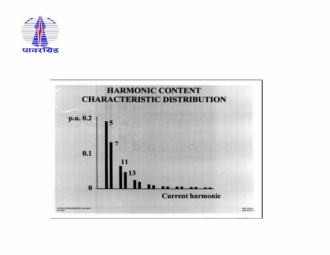
•Supply of AC voltages into two separate circuits feeding the
rectifier bridges with a phase shift of 30 electrical degrees for
reduction of low order harmonics esp. 5th & 7th harmonics.
•As a galvanic barrier between AC and DC systems to prevent
DC potential entering into the AC system
•Reactive Impedance in the AC supply to reduce short circuit
currents and to control the rate of rise in valve current during
commutation.
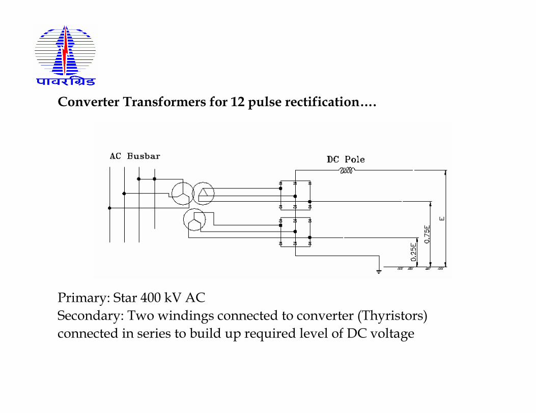
Converter Transformers for 12 pulse rectification….
Primary: Star 400 kV AC
Secondary: Two windings connected to converter (Thyristors)
connected in series to build up required level of DC voltage

– transport restrictions (dimensions and weight)
– number of necessary spare transformers
– technical possible solutions for core and windings
Choice of transformer design is mainly ruled by….
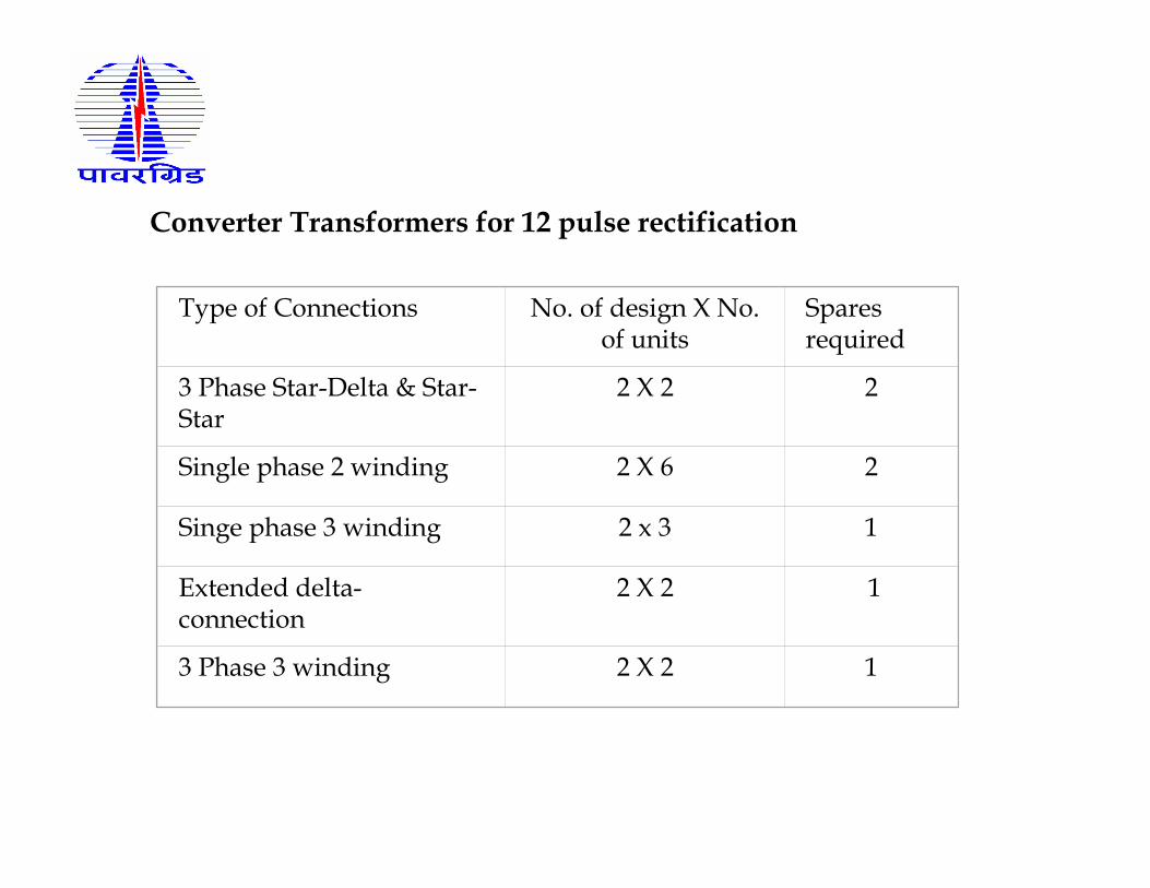
Converter Transformers for 12 pulse rectification
Type of Connections No. of design X No. of units
Spares required
3 Phase Star-Delta & Star-Star
2 X 2 2
Single phase 2 winding 2 X 6 2
Singe phase 3 winding 2 x 3 1
Extended delta-connection
2 X 2 1
3 Phase 3 winding 2 X 2 1
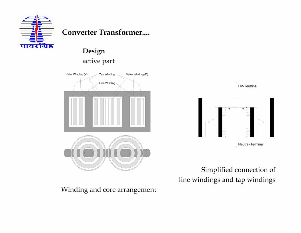
Converter Transformer....
Design
active part
Valve Winding (D)Valve Winding (Y)
Line Winding
Tap Winding
HV-Terminal
Neutral-Terminal
Simplified connection of
line windings and tap windings
Winding and core arrangement
Converter Xmer & Normal AC Xmer…..
• Polarity Reversal
• Voltage Distribution in Oil Barrier System
• Impedance variation influence
• On load Tap Changer
• Harmonic Currents
• Losses
• DC Magnetisation
• Short Circuit Forces
• DC Bushings
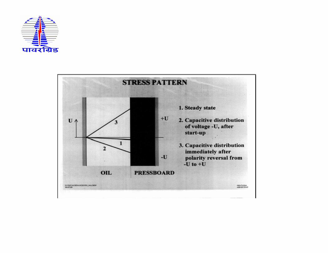
• Beginning voltage stress distributions capacitive – Oil is stressed
more than PB
• Successively change over to Resistive distribution – PB is
stressed more (almost all stress across solid insulation)
• PD stresses under DC – Sporadic pulses at random intervals
-Discharges in oil gaps under rapid changes in voltage
-Discharges in cellulose insulation due to imperfections in
insulation
-Discharges at the oil-cellulose interface
……. To meet above, special oil-barrier insulation system is required
Under Polarity Reversal…..
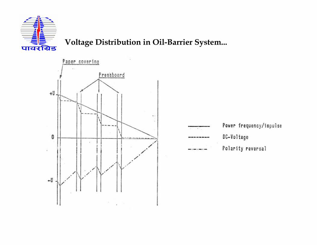
Voltage Distribution in Oil-Barrier System...

• Main duct in HVDC transformers require more PB barriers than normal AC transformers as DC voltage is taken mainly by PB. Voltage distribution is by resistivity in steady state.
- Transient DC voltages:
• Start up of converter when full DC potential from bridges is developed almost instantaneously
- DC Voltage Polarity Reversal:• When direction of power flow is changed in HVDC system, current
direction remains the same while polarity of the voltage will be reversed. • This is done within a few number of power cycles.• A sudden change in DC voltage is capacitive. • Time constant for the transition from capacitive to resistive distribution
is about an hour.
Voltage Distribution in Oil-Barrier System...
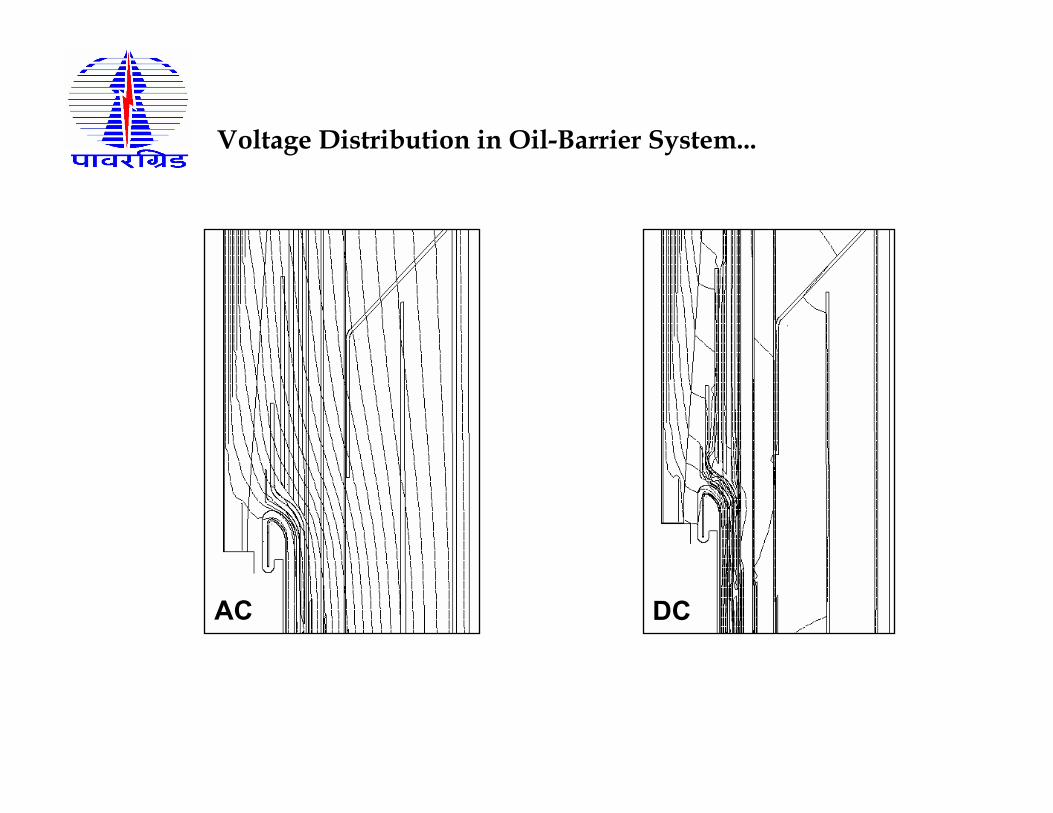
AC DC
Voltage Distribution in Oil-Barrier System...
• Valve windings to withstand AC voltages, superimposed DC
voltages on AC voltages, DC Voltage Polarity Reversal
• Composite insulation of Pressboard or Paper (Solid) and
oil (liquid)
• Voltage distribution between paper & oil under AC conditions
� depends on inverse ratio of dielectric constants of
PB/ Oil (2:1)
• Voltage distribution between oil & paper under steady state
DC voltage � depends on direct ratio of resistivities (1:10 ~ 500),
depends on oil quality, moisture content and temperature
Insulation Design
Closer Tolerance in Impedance is required between three phases and also between upper & lower bridges (star-star, star-delta circuits)
• (± 6% on special tolerance and 2-3% variation between units • (Normal transformers ± 10%)
The above is necessary :• To reduce distortion in DC voltage wave form• To reduce non-characteristic harmonics, thereby cost of AC filters • To reduce residual currents between three phases, which can act
as DC magnetization on the core.
To achieve close tolerance on impedance variation• Close dimensional tolerances in windings• Proper stabilization of windings before assembly• Better insulating material• Good winding machines
Influence of Impedance variation…

• Large voltage control requirements at converter & inverter ends.
Tapping range is large (25 ~ 30%) with small steps to give
necessary adjustments in supply voltage.
• High frequency of operation – Mechanical aspects of OLTC
should be reviewed to ensure a robust design (Contacts wear,
linkages, motor, relays, contactors, interlocks). Derating
necessary compared to normal transformer applications.
• Small step voltage permit small variation in DC voltage, valve
firing angles and reactive power demand
On Load Tap Changer….

• There is need to compensate for the reactive voltage drop in the conversion between AC & DC by changing taps.
• In OLTC, switchover from one tap to another is carried out by the diverter switch.
• When changing over from one tap to next, the current in the leavingtap has to be broken during the normal current zero passage.
• In star-star connected windings, the current is zero for a long time and the change over is smooth.
• But in star-delta connected windings, the current change from positive to negative is abrupt with very little time at zero current.
• This puts strain on diverter switch.
On Load Tap Changer…

• Additional losses due to harmonic currents in valve windings
• Stray flux from harmonic currents can heat up structural members like Yoke Clamps, Tank
• Yoke shunts are used to contain and direct the above leakageflux to core
• Harmonic stray flux can induce larger currents than power frequency stray flux
Higher Harmonic Currents….

• No-Load losses – Depends on applied AC voltage, same as normal transformer
• Load Losses – I2R + Stray loss from circulating currents in windings & metallic parts
from leakage flux
• Circulating current depend on rate of change in winding current and thus leakage
flux.
• With stepwise change in load current during commutation from one valve to
another, the induced voltages will be fairly high to create circulating currents. So
stray losses are increased compared to conventional power transformers.
• Stray losses in windings – Increase as square of harmonic number
• At 150 Hz, Stray losses (150/50)2 more than at 50 Hz current
• Stray losses in metal- varies as 0.8 of harmonic number
• High percentage of harmonic currents in the load current causes higher load losses
compared to normal transformers
Losses….

• Due to inaccuracies in valve firing.
• Results in a small residual DC current oscillating around zero.
• DC components in magnetizing current lead to core saturation, which
results in -
�high levels of vibration
�increased sound level in transformers
�marginal increase in no-load loss.
DC Magnetization….
• A short circuit across a valve or phase to ground on a valve side terminal
can result in a completely asymmetrical current for a few cycles.
• Resulting forces on the winding can be larger than for the normal power
transformers where the asymmetry decays rapidly.
Short Circuit Forces….

Mechanical forces during a short circuit may reach critical values
An inner winding buckles under radial forces
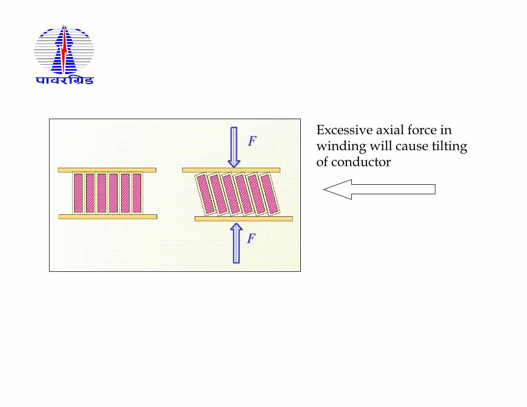
Excessive axial force in winding will cause tilting of conductor
• DC withstand voltage of contaminated insulator is 20 ~ 30% of that of AC.
• To meet this, bushings creepage used are 40 mm/kV or more (Normal
bushings are with 25mm / kV of service maximum voltage)
• To avoid chances of phase to ground short circuits, valve side bushings are
located inside the valve hall. This also reduces the pollution related
flashovers and consequent short circuit.
• IEC & IEEE standards for the DC bushings.
DC Bushing….
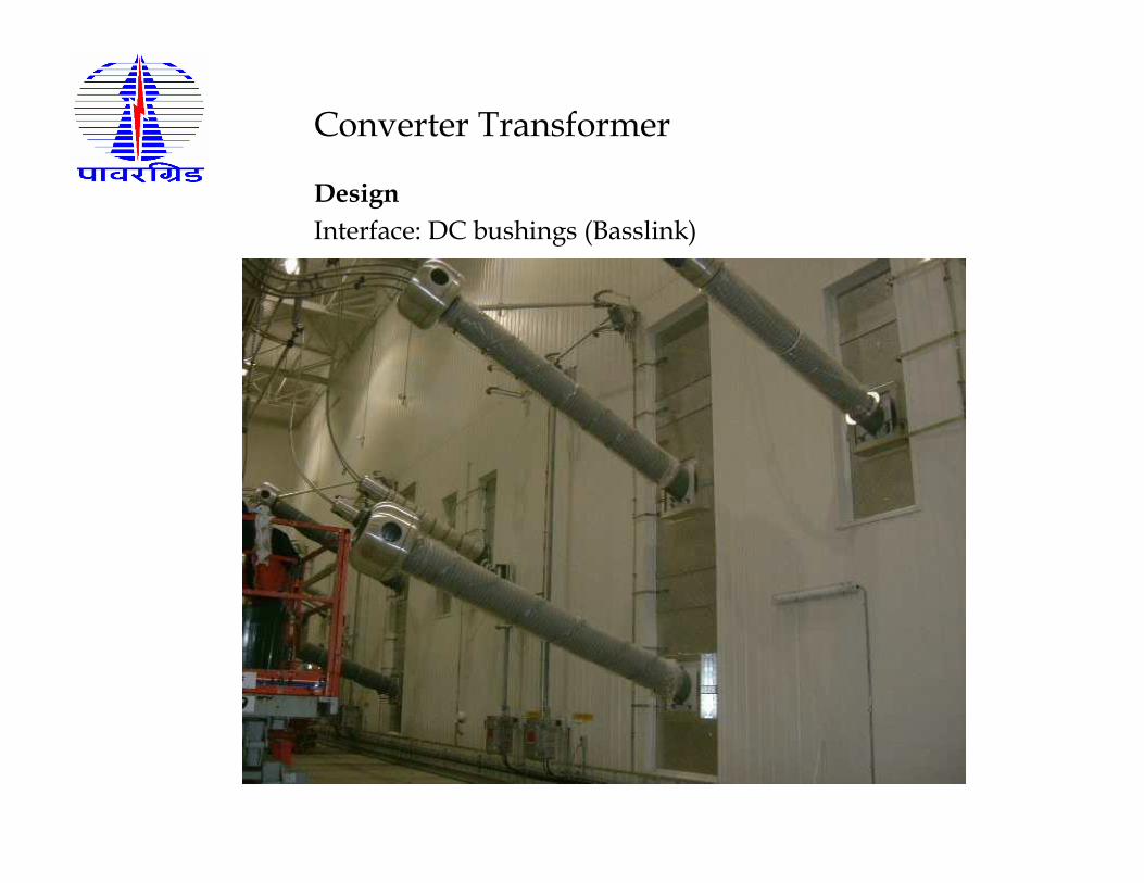
Converter Transformer
Design
Interface: DC bushings (Basslink)
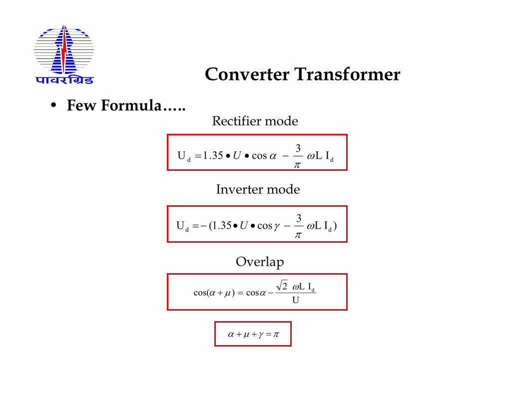
Converter Transformer
• Few Formula…..
dd I L3
cos35.1U ωπ
α −••= U
)I L3
cos35.1(U dd ωπ
γ −••−= U
Rectifier mode
Inverter mode
Overlap
U
IL2cos)cos( dω
αµα −=+
πγµα =++
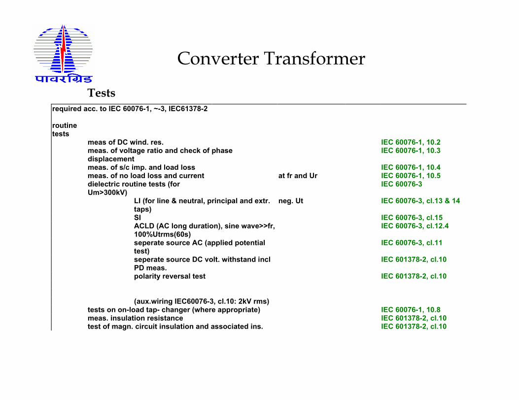
Converter Transformer
Testsrequired acc. to IEC 60076-1, ~-3, IEC61378-2
routine tests
meas of DC wind. res. IEC 60076-1, 10.2 meas. of voltage ratio and check of phase displacement
IEC 60076-1, 10.3
meas. of s/c imp. and load loss IEC 60076-1, 10.4 meas. of no load loss and current at fr and Ur IEC 60076-1, 10.5 dielectric routine tests (for Um>300kV)
IEC 60076-3
LI (for line & neutral, principal and extr. taps)
neg. Ut IEC 60076-3, cl.13 & 14
SI IEC 60076-3, cl.15 ACLD (AC long duration), sine wave>>fr,
100%Utrms(60s) IEC 60076-3, cl.12.4
seperate source AC (applied potential test)
IEC 60076-3, cl.11
seperate source DC volt. withstand incl PD meas.
IEC 601378-2, cl.10
polarity reversal test IEC 601378-2, cl.10 (aux.wiring IEC60076-3, cl.10: 2kV rms) tests on on-load tap- changer (where appropriate) IEC 60076-1, 10.8 meas. insulation resistance IEC 601378-2, cl.10 test of magn. circuit insulation and associated ins. IEC 601378-2, cl.10
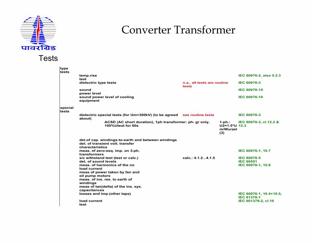
Converter Transformer
Tests type tests
temp.rise test
IEC 60076-2, also 5.2.3
dielectric type tests n.a., all tests are routine tests
IEC 60076-3
sound power level
IEC 60076-10
sound power level of cooling equipment
IEC 60076-10
special tests
dielectric special tests (for Um>300kV) (to be agreed about)
see routine tests IEC 60076-3
ACSD (AC short duration), 1ph transformer: ph- gr only, 100%Utest for 60s
1-ph.: U2=1.5*Um/Wurzel(3)
IEC 60076-3, cl.12.2 & 12.3
det.of cap. windings-to-earth and between windings det. of transient volt. transfer characteristics
meas. of zero-seq. imp. on 3-ph. transformers
IEC 60076-1, 10.7
s/c withstand test (test or calc.) calc.: 4.1.2...4.1.5 IEC 60076-5 det. of sound levels IEC 60551 meas. of harmonics of the no load current
IEC 60076-1, 10.6
meas of power taken by fan and oil pump motors
meas. of ins. res. to earth of windings
meas of tan(delta) of the ins. sys. capacitances
losses and imp.(other taps) IEC 60076-1, 10.4+10.5, IEC 61378-1
load current test
IEC 601378-2, cl.10
Standards:
1) IEC 61378-1 (1.0) 1997-09 Converter Transformers –Part I Transformers for Industrial Applications
2) IEC 61378-2 (1.0) 2001-02 Converter Transformers –Part 2 Transformers for HVDC Applications.
3) IEC 61378-3 (under issue) Converter Transformers –Part 3 Application Guide for Converter Transformers
4) IEC 62199: 2004-05 Bushings for DC Application
5) IEEE Std. C57.129-1999 General Requirements and Test code for Oil Immersed HVDC Converter Transformers.
Standards:
6) IEEE Std. 1158-1991 (R 1996) Recommended Practice for Determination of Power losses in HVDC converter stations.
7) IEEE Std. C57.19.03 - 1996 Standard Requirements, Terminology and Test Code for Bushings for DC applications.
THANK YOU