sarmad riazi, mohammad mahdi feizi, parisa … · sarmad riazi, mohammad mahdi feizi, parisa...
TRANSCRIPT
IMPROVING CRASHWORTHINESS IN RAILCAR AGAINST ROLLOVER
Sarmad Riazi, Mohammad Mahdi Feizi, Parisa Hosseini-TehraniCenter of Excellence in Railway Engineering, School of Railway Engineering,
Iran University of Science and Technology, Tehran, IranE-mail: [email protected]
Received April 2012, Accepted October 2012No. 12-CSME-47, E.I.C. Accession 3367
ABSTRACTRoof strength is critical to survival in rollover accidents in railcars. In this task using LS-DYNA software
different scenarios are examined in order to strengthen railcar roof and to improve the crashworthinessfeatures against rollover. The performance of each scenario is investigated through presenting the resultsof crushing behavior and energy absorption versus displacement response. Eventually, the best solutionproviding the highest ratio of “Energy absorption per Mass” among the studied model is presented.
Keywords: rollovers; roof strength; railcar; crashworthiness.
AMÉLIORATION DE LA RÉSISTANCE À L’IMPACT DES WAGONS DE TRAIN LORS D’UNRENVERSEMENT
RÉSUMÉLa résistance du toit des wagons de train est essentielle à la survie des passagers lors d’un renversement.
Pour cette recherche, différents scénarios sont examinés à l’aide du logiciel LS-DYNA dans le but de ren-forcer le toit des wagons et d’améliorer la résistance à l’impact lors de renversement. La performance dechaque scénario est étudiée à travers les résultats du comportement de résistance à l’écrasement et l’absorp-tion d’énergie versus la réponse de déplacement. Nous présentons la solution la meilleure, celle qui donnaitle plus haut coefficient «d’absorption d’énergie par masse» parmi les modèles étudiés.
Mots-clés : renversement ; résistance du toit ; wagon de train ; résistance à l’impact.
Transactions of the Canadian Society for Mechanical Engineering, Vol. 36, No. 4, 2012 383

1. INTRODUCTION
Roof collapse and buckling are the major cause of rollover head and neck injuries to both ejected and non-ejected occupants. In rollover occupant compartment integrity and good resistance against deformation areessential. In railway industry testing is extremely expensive, new models of railway vehicles circulate andnew passenger cars are put into service without being subjected to experimental testing. However, virtualtesting and numerical modeling may be acceptable in the design cycle.
On the other hand, various performance standards concerning crashworthiness of motor vehicles in caseof rollover accidents have been introduced. Standards like FMVSS 216 (for cars), FMVSS 220 and ECE r66(for buses) are accompanied by numerous publications on the subject.
However, currently, there are few standards and published works addressing the desired behavior of pas-senger railcars in rollover. Due to similarity between structure of transit buses and railcars, and in absenceof a comprehensive rollover test standard for the latter, in a study by Cuartero, J. et al. [1] , the Europeanstandard —ECE r66— has been implemented to study the crashworthiness of a metro car. Although theabove-mentioned study proves such railcars to be exceedingly safe when tested by this standard, an investi-gation on the Waterfall train crash poses concern on safety of the existing fleet, since in their design “rolloveris not generally envisaged or catered to”(Rechnitzer G. et al. [2]).
Inspired by the work of Cuartero et al., a recent paper by the authors of the present work implementedFE software and modified ECE r66 to study the crashworthiness of a section of a passenger railcar. Thatstudy also investigated the effectiveness of usuall methods for strengthening the structure, i.e. using thickercomponents and upgraded steel (Hosseini Tehrani,P. and Riazi, S. [3]). Moreover, in the mentioned study,without any major change in the design of the structure, a certain reinforcing component was installed andproved to be effective.
In this work, the objective is to study a wider range of possibilities for improving crashworthiness ofpassenger railcars. Initially, a variety of reinforcing components are studied without changing the originaldesign of the wagon. Afterward, some changes are made in the profile of main pillars to examine the suit-ability of alternative designs. Eventually, the best solution providing the highest ratio of “Energy absorptionper Mass” among the studied model is achieved.
2. NUMERICAL MODEL
2.1. Body PartsBased on a number of published works on buses, it is clear that it is computationally cost effective to per-
form the numerical analysis on a “segment” of a bus. This method is approved by ECE r66 (Addendum 65:Regulation No. 66, 2006). Therefore, According to the definition given in the standard for a segment, in thispaper a section of the railcar is chosen and shown in Fig. 1. The shown sections are later referred to as BaseModel and consist of the following parts:
1. The underframe, including longitudinal and lateral beams;
2. The side walls, composed of vertical pillars and horizontal rails;
3. The top flange, connecting the pillars to the roof structure;
4. The roof structure, including arches, rails and bars.
2.2. Initial and Boundary ConditionsAs illustrated in Fig. 2, a moving rigid wall hits the wagon structure at an angle of 19.5 degrees. The rigid
wall has a mass of 2580.75 kg and its initial velocity is considered 5 m/s.
384 Transactions of the Canadian Society for Mechanical Engineering, Vol. 36, No. 4, 2012

Fig. 1. Main dimensions of the chosen section (in meters), on which analyses are performed.
The wagon is assumed to be stationary and the shell elements at the lowest part of the underframe haveno degrees of freedom. This is to avoid the modeling difficulties of the tilting bench method (Addendum 65:Regulation No. 66 [4]) and to provide pure crash event resulting in shorter simulation time.
Fig. 2. The rigid wall hitting the wagon section.
2.3. ElementsThe CAD model is based on a structure used by Wagon Pars Company for passenger railcar. FE model of
this section is made by 16107 four-node shell elements with Belytschko-Tsay formulation.
3. SIMULATION SCENARIOS
3.1. Reinforcing ComponentsTable 1 shows different phases of the simulations. Analysis 0 represents base model, i.e. original railcar
as designed by the manufacturer.Analyses 1 through 3 are designed to investigate the effect of thickness change of the crossbar, a rein-
forcing component that is added to the base model as shown in Fig. 3. In these analyses the thickness isincreased by the increment of 1 mm. the thickness of crossbar used in the first model is considered 2 mm.
Analysis 4 introduces another component —the bottom stiffeners—, which strengthen the joints betweenthe underframe and the pillars as illustrated in Fig. 4. It is then followed by analysis 5 that studies anothertype of stiffeners with the same area but different dimensions as shown in Fig. 5.
Transactions of the Canadian Society for Mechanical Engineering, Vol. 36, No. 4, 2012 385

Fig. 3. The crossbar mounted on the structure.
Fig. 4. The stiffeners type 1.
Fig. 5. The stiffeners type 2.
Analysis 6 addresses the use of top stiffeners along with the crossbar type 1, to stiffen the pillar-crossbarjoints (Fig. 6). Further, analysis 7 deals with the use of the top stiffeners and crossbar type 3. Also, analy-sis 8 studies the combined effect of the crossbar, bottom and top stiffeners as indicated in Fig 7.
Fig. 6. The top stiffeners and crossbar.
386 Transactions of the Canadian Society for Mechanical Engineering, Vol. 36, No. 4, 2012

!
Analysis No.
Component
Crossbar thickness
Bottom stiffeners
Top stiffeners
Reinforcing box
Reinforcing plates
Pillar type
Material Number of roof arches
S- profile
Box- profile
St- 52 Al
2 3 4 1 2 4 5 6
0 (base model)
! ! !
1 ! ! ! !
2 ! ! ! !
3 ! ! ! !
4 ! ! ! !
5 ! ! ! !
6 ! ! ! ! !
7 ! ! ! ! !
8 ! ! ! ! ! !
9 ! ! ! ! !
10 ! ! ! ! ! !
11 ! ! ! ! !
12 ! ! ! ! !
13 ! ! ! ! ! !
14 ! ! ! !
15 ! ! ! !
16 ! ! ! !
17 ! ! ! !
!
Table!1! !Table 1. Analysis Scenarios.
The concept of a reinforcing box (Fig. 8) is introduced in analysis 9 where it is used along with bottomstiffeners.
This configuration is combined with the crossbars in analysis 10. In analysis 11, the combined effect ofbottom stiffeners and crossbars are investigated (Fig. 9).
Analysis 12 addresses the use of Reinforcing Plates and the bottom stiffeners as shown in Fig. 10, whileanalysis 13 supplements this design by the use of crossbars.
Transactions of the Canadian Society for Mechanical Engineering, Vol. 36, No. 4, 2012 387

Fig. 7. The combined use of top and bottom stiffeners and crossbar.
Fig. 8. The box-shaped reinforcements mounted on the bottom stiffeners.
Fig. 9. Bottom stiffeners and crossbar.
Fig. 10. The reinforcing plates strengthen the s-profile of the pillars.
388 Transactions of the Canadian Society for Mechanical Engineering, Vol. 36, No. 4, 2012
3.2. Alternative DesignsIn contrast to simulations presented in the former section, in alternative solutions, there will be consid-
erably less fidelity to the original design i.e. pillar profile undergoes some modifications. The last row ofTable 1 shows the simulation scenarios for the alternative designs.
Analysis 0 is the original model with s-profile used in the pillars. In Analysis 14 the s-profiles of the mainpillars are replaced with box type counterparts. In Analysis 15 aluminum box-profile pillars are used.
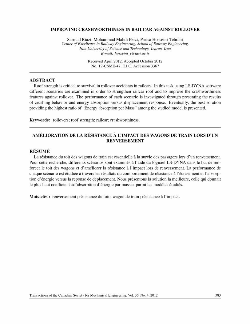
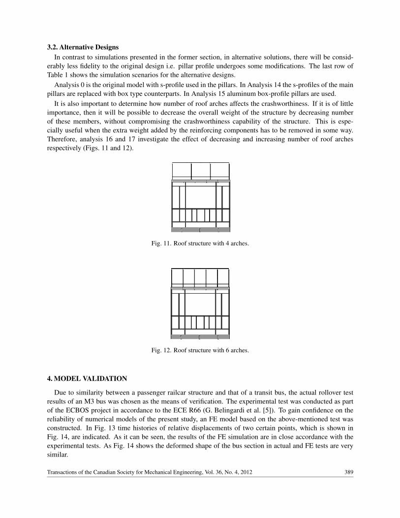
It is also important to determine how number of roof arches affects the crashworthiness. If it is of littleimportance, then it will be possible to decrease the overall weight of the structure by decreasing numberof these members, without compromising the crashworthiness capability of the structure. This is espe-cially useful when the extra weight added by the reinforcing components has to be removed in some way.Therefore, analysis 16 and 17 investigate the effect of decreasing and increasing number of roof archesrespectively (Figs. 11 and 12).
Fig. 11. Roof structure with 4 arches.
Fig. 12. Roof structure with 6 arches.
4. MODEL VALIDATION
Due to similarity between a passenger railcar structure and that of a transit bus, the actual rollover testresults of an M3 bus was chosen as the means of verification. The experimental test was conducted as partof the ECBOS project in accordance to the ECE R66 (G. Belingardi et al. [5]). To gain confidence on thereliability of numerical models of the present study, an FE model based on the above-mentioned test wasconstructed. In Fig. 13 time histories of relative displacements of two certain points, which is shown inFig. 14, are indicated. As it can be seen, the results of the FE simulation are in close accordance with theexperimental tests. As Fig. 14 shows the deformed shape of the bus section in actual and FE tests are verysimilar.
Transactions of the Canadian Society for Mechanical Engineering, Vol. 36, No. 4, 2012 389

Fig. 13. Time histories of relative displacements.
Fig. 14. Comparison between the experimental [5] and FE models.
5. SIMULATION RESULTS
Analysis 0 of Table 1 refers to the rollover test of the main model. As it is shown in Fig. 15, whilethe kinematic energy of the rigid wall decreases, the internal energy increases and the total energy remainsalmost constant. Moreover, hourglass energy is little.
According to ECE r66, the permissible amount of non-physical energy components like “hourglass”, ismaximum 5 % of total energy [4]. In analysis 0, satisfaction of this condition ensures the right energybalance. In addition, for the rest of the simulations in this research, hourglass energy is little and lieswithin the mentioned criteria. First order reduced-integration elements (which happen to be the very typeof elements generally used in explicit solvers) suffer from hourglassing. These elements only have oneintegration point; because of this the elements can shear without introducing any energy. FEA codes whichrely on 1st order reduced integration elements counter this by introducing hourglass energy. In situationswhere these elements would otherwise shear, this augmented energy keeps this from happening. This isreflected in the reported hourglass energy values. High hourglassing energy is often a sign that mesh issuesmay need to be addressed. Figure 16 depicts the results of analyses 0 through 3. As seen, the use ofcrossbar (analysis 1) has significantly increased the absorbed energy. In the absence of crossbars, for any
390 Transactions of the Canadian Society for Mechanical Engineering, Vol. 36, No. 4, 2012

Fig. 15. Energy absorption versus time.
given distance that rigid wall travels, the right sidewall undergoes more deformation than the left wall,which means less participation of the left wall in energy absorption. But, when the crossbars are present,for the same displacement of the rigid wall, the left sidewall absorbs more energy and the deformation ofthe structure is more symmetrical which leads in higher overall energy absorption (Fig. 17a,b). It can alsobe seen that thicker crossbars result in slightly higher energy absorption. It is now appropriate to define
Fig. 16. Absorbed energy for analyses 0 to 3.
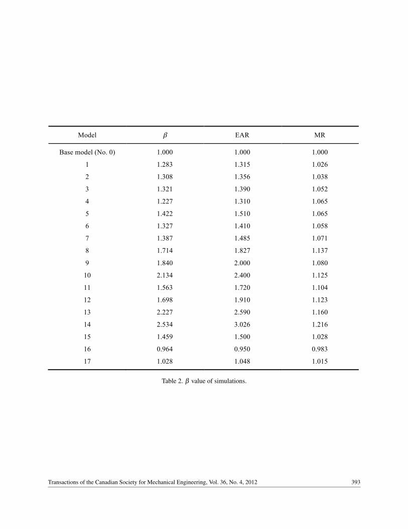
a dimensionless value of β . According to Eq. (1), a ratio of absorbed energy of each model per absorbedenergy of base model (EAR) is defined, and then in order to compute the value of β (Eq. 3) this ratio isdivided by the mass ratio (MR) which is defined by Eq. (2).
Use of dimensionless parameter β facilitates the comparison between suitability of each improvementmethod. For example as Table 2 indicates, for analysis 1 through 3, even when thicker and heavier crossbarsare used, β is increased.
EAR =internal energy o f each simulation
internal energy o f base model, (1)
MR =mass o f each simulation
mass o f base model. (2)
Transactions of the Canadian Society for Mechanical Engineering, Vol. 36, No. 4, 2012 391
(a) (b)
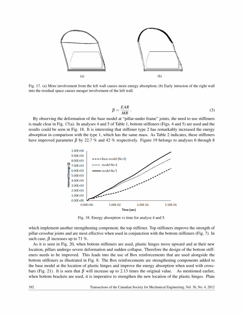
Fig. 17. (a) More involvement from the left wall causes more energy absorption; (b) Early intrusion of the right wallinto the residual space causes meager involvement of the left wall.
β =EARMR
. (3)
By observing the deformation of the base model at “pillar-under frame” joints, the need to use stiffenersis made clear in Fig. 17(a). In analyses 4 and 5 of Table 1, bottom stiffeners (Figs. 4 and 5) are used and theresults could be seen in Fig. 18. It is interesting that stiffener type 2 has remarkably increased the energyabsorption in comparison with the type 1, which has the same mass. As Table 2 indicates, these stiffenershave improved parameter β by 22.7 % and 42 % respectively. Figure 19 belongs to analyses 6 through 8
Fig. 18. Energy absorption vs time for analyse 4 and 5.
which implement another strengthening component, the top stiffener. Top stiffeners improve the strength ofpillar-crossbar joints and are most effective when used in conjunction with the bottom stiffeners (Fig. 7). Insuch case, β increases up to 71 %.
As it is seen in Fig. 20, when bottom stiffeners are used, plastic hinges move upward and at their newlocation, pillars undergo severe deformation and sudden collapse. Therefore the design of the bottom stiff-eners needs to be improved. This leads into the use of Box reinforcements that are used alongside thebottom stiffeners as illustrated in Fig. 8. The Box reinforcements are strengthening components added tothe base model at the location of plastic hinges and improve the energy absorption when used with cross-bars (Fig. 21). It is seen that β will increase up to 2.13 times the original value. As mentioned earlier,when bottom brackets are used, it is imperative to strengthen the new location of the plastic hinges. Plate
392 Transactions of the Canadian Society for Mechanical Engineering, Vol. 36, No. 4, 2012
Model β EAR MR
Base model (No. 0) 1.000 1.000 1.000
1 1.283 1.315 1.026
2 1.308 1.356 1.038
3 1.321 1.390 1.052
4 1.227 1.310 1.065
5 1.422 1.510 1.065
6 1.327 1.410 1.058
7 1.387 1.485 1.071
8 1.714 1.827 1.137
9 1.840 2.000 1.080
10 2.134 2.400 1.125
11 1.563 1.720 1.104
12 1.698 1.910 1.123
13 2.227 2.590 1.160
14 2.534 3.026 1.216
15 1.459 1.500 1.028
16 0.964 0.950 0.983
17 1.028 1.048 1.015
!
Table!2!
! !
Table 2. β value of simulations.
Transactions of the Canadian Society for Mechanical Engineering, Vol. 36, No. 4, 2012 393

Fig. 19. Absorbed energy vs. time for analyses 6 through 8.
(a) (b)
Fig. 20. Deformed shapes (a) of model 9 and (b) of model 10.
Fig. 21. Absorbed energy for analyses 9 and 10.
reinforcements in models 12 and 13 (Fig. 10) are another design to eliminate this shortcoming. As Fig. 22indicates, this design results in energy absorption of 16 KJ or about 2.5 times of the original design whenused with crossbars in model 13.
394 Transactions of the Canadian Society for Mechanical Engineering, Vol. 36, No. 4, 2012

Fig. 22. Absorbed energy vs. time for analyses 12 and 13.
It is useful to know how the original pillar profiles could affect the energy absorption during rollover.According to Table 2, in analyses 1 and 2, the s-shaped profiles have been replaced with box profiles, andinstead of the original steel in analysis 2, aluminum has been used. Table 3 states specifications of steel andaluminum used. As Fig. 23 shows, the use of steel box profile has significantly increased the absorbed
Material Density Young’s Poisson’s Yield stress (Kg/m3) Modulus (Pa) ratio (Pa)
Steel 7850 2.1E11 0.3 6.21E8
Aluminium 2700 6.9E10 0.33 2.75E7
!
Table!3!Table 3. Steel and aluminum specifications.
Fig. 23. Absorbed energy vs. time for analyses 14 and 15.
Transactions of the Canadian Society for Mechanical Engineering, Vol. 36, No. 4, 2012 395
energy, compared with the base model. Also, aluminum box-profiles have improved this feature too. Itis interesting that changing the pillar profiles increased β for 2.53 and 1.49 times the original design forsteel and aluminum pillars respectively.
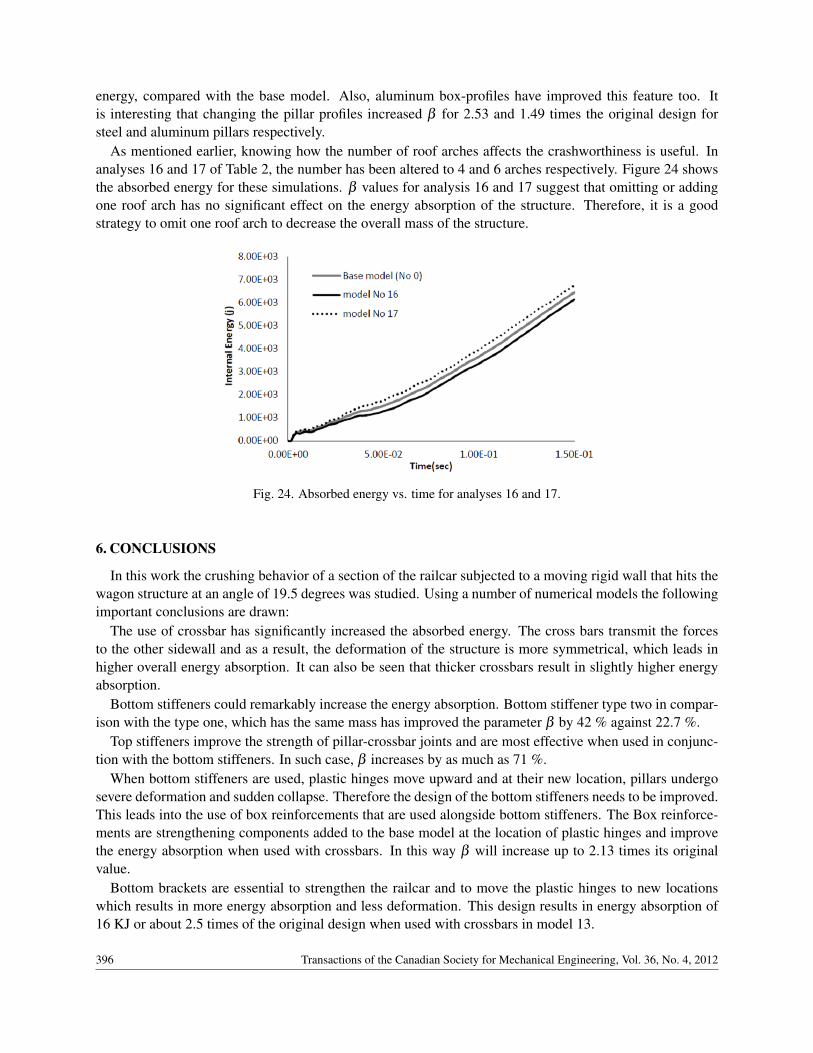
As mentioned earlier, knowing how the number of roof arches affects the crashworthiness is useful. Inanalyses 16 and 17 of Table 2, the number has been altered to 4 and 6 arches respectively. Figure 24 showsthe absorbed energy for these simulations. β values for analysis 16 and 17 suggest that omitting or addingone roof arch has no significant effect on the energy absorption of the structure. Therefore, it is a goodstrategy to omit one roof arch to decrease the overall mass of the structure.
Fig. 24. Absorbed energy vs. time for analyses 16 and 17.
6. CONCLUSIONS
In this work the crushing behavior of a section of the railcar subjected to a moving rigid wall that hits thewagon structure at an angle of 19.5 degrees was studied. Using a number of numerical models the followingimportant conclusions are drawn:
The use of crossbar has significantly increased the absorbed energy. The cross bars transmit the forcesto the other sidewall and as a result, the deformation of the structure is more symmetrical, which leads inhigher overall energy absorption. It can also be seen that thicker crossbars result in slightly higher energyabsorption.
Bottom stiffeners could remarkably increase the energy absorption. Bottom stiffener type two in compar-ison with the type one, which has the same mass has improved the parameter β by 42 % against 22.7 %.
Top stiffeners improve the strength of pillar-crossbar joints and are most effective when used in conjunc-tion with the bottom stiffeners. In such case, β increases by as much as 71 %.
When bottom stiffeners are used, plastic hinges move upward and at their new location, pillars undergosevere deformation and sudden collapse. Therefore the design of the bottom stiffeners needs to be improved.This leads into the use of box reinforcements that are used alongside bottom stiffeners. The Box reinforce-ments are strengthening components added to the base model at the location of plastic hinges and improvethe energy absorption when used with crossbars. In this way β will increase up to 2.13 times its originalvalue.
Bottom brackets are essential to strengthen the railcar and to move the plastic hinges to new locationswhich results in more energy absorption and less deformation. This design results in energy absorption of16 KJ or about 2.5 times of the original design when used with crossbars in model 13.
396 Transactions of the Canadian Society for Mechanical Engineering, Vol. 36, No. 4, 2012
The use of steel box profile has significantly increased the absorbed energy, compared with the basemodel. Also, aluminum box-profiles have improved this feature too. It is interesting that changing the pillarprofiles increased β for 2.53 and 1.49 times the original design for steel and aluminum pillars respectively.
It is shown that omitting or adding one roof arch has no significant effect on the energy absorption of thestructure. Therefore, it is a good strategy to omit one roof arch to decrease the overall mass of the structure.
REFERENCES
1. Cuartero, J., Lizaranzu, M., Castejón, L., Carrera, M. and Dieste, M.,“Evaluation of passenger railroad carrollover crashworthiness”, International Journal of Crashworthiness, Vol. 11, No. 5, pp. 419–424, 2006.
2. Rechnitzer, G., McIntosh, A., Richardson, S., Grzebieta, R. and Jaraie, J., “Crashworthiness improvements forlight and heavy rail—lessons learnt from crash investigations”, Center for auto safety report, document ID:NHTSA–2008–0015–0039, 2008.
3. Hosseini Tehrani, P. and Riazi, S., “Crashworthiness improvement of a passenger railcar against rollover” In-ternational Conference on Mechanical Automotive and Aerospace Engineering (ICMAAE’11), Kualalumpur,Malaysia, May 2011.
4. Addendum 65: Regulation No. 66, “Uniform technical prescriptions concerning the approval of large passengervehicles with regard to the strength of their superstructure”, pp. 61–95, 2006.
5. Belingardi, G., Gastaldin, D., Martella, P. and Peroni, L., “Multibody analysis of M3 bus rollover: structuralbehavior and passenger injury risk”, Proceedings of 18th International Technical Conference on the EnhancedSafety of Vehicles, Nagoya, Japan, 2003.
Transactions of the Canadian Society for Mechanical Engineering, Vol. 36, No. 4, 2012 397