sa.santhosh
TRANSCRIPT
8/4/2019 SA.SANTHOSH
http://slidepdf.com/reader/full/sasanthosh 1/41
TRAINING REPORT
SA.SANTHOSH SUMMER TRAINEE
2011
SRM UNIVERSITY
CONTROL & INSTRUMENTATION PROJECT
ENGINEERING MANAGEMENT BHEL, NOIDA

8/4/2019 SA.SANTHOSH
http://slidepdf.com/reader/full/sasanthosh 2/41
ACKNOWLEDGEMENT
I take this opportune moment to express my deep sense of gratitude to
Mr. KAMAL SHARMA (ENGINEER C&I) for his unstinted support
and encouragement to me. I express my heartfelt thanks to the
Department Head Mr. K.R. BHARADWAJ (C&I) and Mr.
S.BHATNAGAR (Section Head – I01, C&I) for being a source of
guidance and inspiration for me during this period. Their wonderful style
of mentoring has surely made my training period a great learning
experience. I would also like to offer my indebtedness to Mr. Kamal
Kumar (ENGINEER C&I) for his ever willingness to extend technical
support through out this period. I express my sincere thanks to all the
members of C&I Dept. for their friendly and helpful attitude.
29.06.11
3

8/4/2019 SA.SANTHOSH
http://slidepdf.com/reader/full/sasanthosh 3/41
ABSTRACT
The purpose of this report is to give a brief idea about what has
been done in the training. This report comprises of various
activities/orientation programmes constituting the training.
Broadly, the various activities which made a part of our training
were PEM familiarization, familiarization with work
particularly in C&I and finally the day to day learning of the
routine work in the department.
4

8/4/2019 SA.SANTHOSH
http://slidepdf.com/reader/full/sasanthosh 4/41
TABLE OF CONTENTS
ACKNOWLEDGEMENT 3
ABSTRACT 4
1. About the Company 6
2. About the Department 8
3. Role of C&I 9
4. Overview of power plant 10
5. P&ID-Introduction 18
6. KKS Identification Scheme 19
7. Instrument Schedule 20
8. Control System 22
8.1 Binary Control System 26
8.1.1 Sequence Control Scheme 28
9. Conclusion 37
5

8/4/2019 SA.SANTHOSH
http://slidepdf.com/reader/full/sasanthosh 5/41
About The Company
BHEL is the largest engineering and manufacturing enterprise in India in the
energy related/infrastructure sector, today.
BHEL’s vision is to become a world class engineering enterprise, commited to
enhance stakeholder value. The company is striving to give shape to itsaspirations and fulfill the expectation as a ‘Navratna’ Company.
BHEL manufactures over 180 products under 30 major product groups and
caters to core sectors of the Indian Economy viz., Power Generation &
Transmission, Industry, Transportation, Telecommunication, Renewable
Energy, etc.
The wide network of BHEL's 15 manufacturing divisions, four Power Sector
regional centres, over 100 project sites, eight service centres and 18 regionaloffices, enables the Company to promptly serve its customers and provide them
with suitable products, systems and services efficiently and at competitive
prices.
The high level of quality & reliability of its products is due to the emphasis on
design, engineering and manufacturing to international standards by acquiring
and adapting some of the best technologies from leading companies in the
world, together with technologies developed in its own R&D centres.
BHEL has acquired certifications to Quality Management Systems (ISO 9001),
Environmental Management Systems (ISO 14001) and Occupational Health &
Safety Management Systems (OHSAS 18001) and is also well on its journey
towards Total Quality Management.
BHEL has:
• Installed equipment for over 100,000 MW of power generation for utilities,
captive and industrial users.
6
8/4/2019 SA.SANTHOSH
http://slidepdf.com/reader/full/sasanthosh 6/41
• Supplied over 2,25,000 MVA transformer capacity and sustained
equipment operating in transmission & distribution network up to 400 KV
AC & DC.
• Supplied over 25,000 motors with Drive Control System to Power project,
Petrochemicals, Refineries, Steel, Aluminium, Fertilizer, Cement plant etc.• Supplied Traction electrics and AC/DC losses to power over 12,000 Kms
Railway network.
• Supplied over one million values to Power Plants and other industries.
BHEL’s operations are organized around three business sectors, namely:
Power, Industry including Transmission, Transportation, Telecommunication
& Renewable Energy and
Overseas Business.
This enables BHEL to have a strong customer orientation, to be sensitive to his needs
& to respond quickly to the changes in the market.
The greatest strength of BHEL is its highly skilled and committed 46,848 employees.
Every employee is given an equal opportunity to develop himself and grow in his
career. Continuous training and retraining, career planning, a positive work culture
and participative style of management. All these have engendered development of a
committed and motivated workforce setting new benchmarks in terms of productivity,
quality and responsiveness.
Project Engineering Management
Project Engineering Management Division (PEM) is a division within
the power group to provide total Systems Engineering for BHEL
equipment, as well as for procurement, erection & commissioning of non
BHEL systems & equipment for thermal power stations.
BHEL business is in the field of power generation equipment, which is
handled by the Power Group and covers all the services related to power
projects from concept to commissioning in keeping with the corporate
aim of developing BHEL into a world class engineering organization.
Power Generation Sector comprises thermal, gas, hydro and nuclear
power plant business. As of 31.3.2006, BHEL supplied sets account for
7

8/4/2019 SA.SANTHOSH
http://slidepdf.com/reader/full/sasanthosh 7/41
76,741 MW or nearly 65 percent of the total installed capacity of
1,18,561 MW in the country, as against Nil till 1969 70.
In view of the high degree of technical excellence achieved, there is an
ever increasing participation in National & International Power Projects.
About The Department
Name of the department: Control & Instrumentation(C&I)
Instrumentation & control is widely used collective term covering two
distinct aspects of plant operation. Instruments are those items attached to
8

8/4/2019 SA.SANTHOSH
http://slidepdf.com/reader/full/sasanthosh 8/41
a plant, which gives an indication to the operator of the conditions that
exists within the safety limits & operational parameters for which the
plant was designed. Examples of indicative quantities are operating
pressures, temperatures, flows & level etc.
9
8/4/2019 SA.SANTHOSH
http://slidepdf.com/reader/full/sasanthosh 9/41
Role of Control & Instrumentation (C&I)
INTRODUCTION
The main objective of C&I is to select & mark the proper instruments on process
diagrams, prepare the list of instruments, control logics (analog& binary),
control room layout, cable schedule, cable termination details etc. In C&I
dept. plant schematics are prepared by using Auto Cad software for
implementation on CRT’s for control & monitoring the plant by their
electronics division namely BHEL EDN Bangalore (sister unit).
All control logics are also being translated to software i.e. max–DNA control system
by BHEL EDN.The “unit overview” scheme shows the various equipments of the plant & Main
operating process parameters which are real time parameters in nature & all the
indications related to temperature, pressure, flow, levels etc. are displayed
automatically on CRTs, in case of some fault or malfunctioning the automatic alarm is
blinked on CRT for operator’s action in main control room.
C&I ENGINEERING OUTPUTS
1. Design philosophy for C&I.
2. Design philosophy for HMI.
3. Analog/Binary drive control philosophy.
4. Alarm.
5. Power supplies.
6. Cabling philosophy.
7. Control panels arrangement/locations and UCB
8. Marking of Instruments on P&ID’s .9. Instrument Schedule.
10. Root Valve Schedule.
11. Drive List.
12. Binary/Sequence Control Logic Diagrams including Unit
Integrated Scheme.
13. Analog Control and Measuring Schemes.
14. I/O List (Analog and Digital).
15. Control Valve data sheet.
10

8/4/2019 SA.SANTHOSH
http://slidepdf.com/reader/full/sasanthosh 10/41
16. Flow element data sheet.
17. SWAS(Steam and Water Analyser System).
18. Technical specification and BOM.
19. Control room and SWAS layout.
Overview of Power Plant
THERMAL POWER PLANT
11

8/4/2019 SA.SANTHOSH
http://slidepdf.com/reader/full/sasanthosh 11/41
12

8/4/2019 SA.SANTHOSH
http://slidepdf.com/reader/full/sasanthosh 12/41
A thermal power station near Sofia, Bulgaria
A thermal power station comprises all of the equipment and systems
required to produce electricity by using a steam generating boiler fired
with fossil fuels or biofuels to drive an electrical generator. Some prefer
to use the term energy center because such facilities convert forms of
energy, like nuclear energy, gravitational potential energy or heat energy
(derived from the combustion of fuels) into electrical energy. However,
power plant is the most common term in the United States, while power
station prevails in many Commonwealth countries and especially in the
United Kingdom.
Such power stations are most usually constructed on a very large scale
and designed for continuous operation.
13

8/4/2019 SA.SANTHOSH
http://slidepdf.com/reader/full/sasanthosh 13/41
Diagram of a typical coal fired thermal power station
Typical diagram of a coal fired therm- al power station
1. Cooling tower10. Steam control
valve19. Superheater
2. Cooling water pump11. High pressure
steam turbine
20. Forced draught
(draft) fan
3. Three phase
transmission line12. Deaerator 21. Reheater
4. Step up transformer 13. Feedwater heater22. Combustion air
intake
5. Electrical generator 14. Coal conveyor 23. Economiser
6. Low pressure steam
turbine15. Coal hopper 24. Air preheater
7. Boiler feedwater pump 16. Coal pulverizer 25. Precipitator
8. Surface condenser 17. Boiler steam drum26. Induced draught
(draft) fan
14
8/4/2019 SA.SANTHOSH
http://slidepdf.com/reader/full/sasanthosh 14/41
9. Intermediate pressure
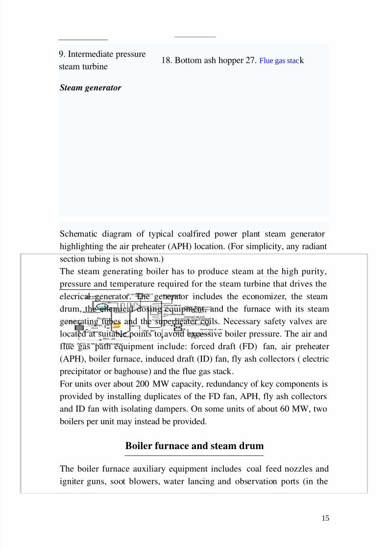
steam turbine18. Bottom ash hopper 27. Flue gas stac k
Steam generator
Schematic diagram of typical coal fired power plant steam generator
highlighting the air preheater (APH) location. (For simplicity, any radiant
section tubing is not shown.)
The steam generating boiler has to produce steam at the high purity,
pressure and temperature required for the steam turbine that drives the
elecrical generator. The generator includes the economizer, the steam
drum, the chemical dosing equipment, and the furnace with its steam
generating tubes and the superheater coils. Necessary safety valves are
located at suitable points to avoid excessive boiler pressure. The air and
flue gas path equipment include: forced draft (FD) fan, air preheater
(APH), boiler furnace, induced draft (ID) fan, fly ash collectors (electric
precipitator or baghouse) and the flue gas stack .
For units over about 200 MW capacity, redundancy of key components isprovided by installing duplicates of the FD fan, APH, fly ash collectors
and ID fan with isolating dampers. On some units of about 60 MW, two
boilers per unit may instead be provided.
Boiler furnace and steam drum
The boiler furnace auxiliary equipment includes coal feed nozzles and
igniter guns, soot blowers, water lancing and observation ports (in the
15

8/4/2019 SA.SANTHOSH
http://slidepdf.com/reader/full/sasanthosh 15/41
furnace walls) for observation of the furnace interior. Furnace explosions
due to any accumulation of combustible gases after a trip out are avoided
by flushing out such gases from the combustion zone before igniting the
coal.
The steam drum (as well as the superheater coils and headers) have air
vents and drains needed for initial startup. The steam drum has internal
devices that removes moisture from the wet steam entering the drum from
the steam generating tubes. The dry steam then flows into the superheater
coils.
Fuel preparation system
In coal fired power stations, the raw feed coal from the coal storage area
is first crushed into small pieces and then conveyed to the coal feed
hoppers at the boilers. The coal is next pulverized into a very fine
powder. The pulverizers may be ball mills, rotating drum grinders, or
other types of grinders.
Some power stations burn fuel oil rather than coal. The oil must kept
warm (above its pour point) in the fuel oil storage tanks to prevent the oil
from congealing and becoming unpumpable. The oil is usually heated to
about 100°C before being pumped through the furnace fuel oil spray
nozzles.
Boilers in some power stations use processed natural gas as their main
fuel. Other power stations may use processed natural gas as auxiliary fuel
in the event that their main fuel supply (coal or oil) is interrupted. In such
cases, separate gas burners are provided on the boiler furnaces.
Fuel firing system and igniter system
From the pulverized coal bin, coal is blown by hot air through the furnace
coal burners at an angle which imparts a swirling motion to the powdered
coal to enhance mixing of the coal powder with the incoming preheated
combustion air and thus to enhance the combustion.
To provide sufficient combustion temperature in the furnace before
igniting the powdered coal, the furnace temperature is raised by first
16

8/4/2019 SA.SANTHOSH
http://slidepdf.com/reader/full/sasanthosh 16/41
burning some light fuel oil or processed natural gas (by using auxiliary
burners and igniters provide for that purpose).
Air path
External fans are provided to give sufficient air for combustion. The
forced draft fan takes air from the atmosphere and, first warming it in the
air preheater for better combustion, injects it via the air nozzles on the
furnace wall.
The induced draft fan assists the FD fan by drawing out combustible
gases from the furnace, maintaining a slightly negative pressure in the
furnace to avoid backfiring through any opening. At the furnace outlet,and before the furnace gases are handled by the ID fan, fine dust carried
by the outlet gases is removed to avoid atmospheric pollution. This is an
environmental limitation prescribed by law, and additionally minimizes
erosion of the ID fan.
Auxiliary systems Fly ash collection
Fly ash is captured and removed from the flue gas by electrostatic
precipitators or fabric bag filters (or sometimes both) located at the outlet
of the furnace and before the induced draft fan. The fly ash is periodically
removed from the collection hoppers below the precipitators or bag
filters. Generally, the fly ash is pneumatically transported to storage silos
for subsequent transport by trucks or railroad cars.
Steam turbine driven electric generator
The steam turbine driven generators have auxiliary systems enabling
them to work satisfactorily and safely. The steam turbine generator being
rotating equipment generally has a heavy, large diameter shaft. The shaft
therefore requires not only supports but also has to be kept in position
while running. To minimise the frictional resistance to the rotation, the
shaft has a number of bearings. Oil lubrication is provided to further
17
8/4/2019 SA.SANTHOSH
http://slidepdf.com/reader/full/sasanthosh 17/41
reduce the friction between shaft and bearing surface and to limit the heat
generated.
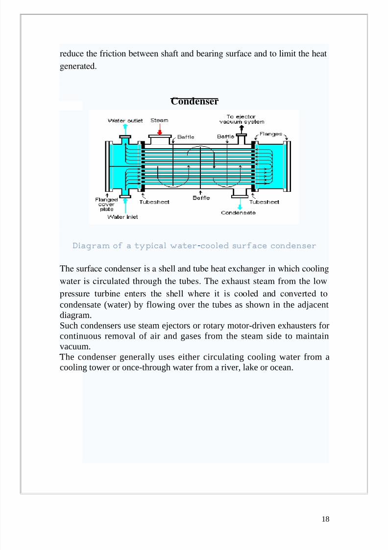
Condenser
Diagram of a typical water cooled surface condenser-
The surface condenser is a shell and tube heat exchanger in which cooling
water is circulated through the tubes. The exhaust steam from the low
pressure turbine enters the shell where it is cooled and converted to
condensate (water) by flowing over the tubes as shown in the adjacentdiagram.Such condensers use steam ejectors or rotary motor-driven exhausters forcontinuous removal of air and gases from the steam side to maintainvacuum.The condenser generally uses either circulating cooling water from acooling tower or once-through water from a river, lake or ocean.
18

8/4/2019 SA.SANTHOSH
http://slidepdf.com/reader/full/sasanthosh 18/41
DEARATOR
Diagram of boiler feed water deaerator (with vertical, domed aerationsection and horizontal water storage section
A steam generating boiler requires that the boiler feed water should be
devoid of air and other dissolved gases, particularly corrosive ones, in
order to avoid corrosion of the metal.
Generally, power stations use a deaerator to provide for the removal of
air and other dissoved gases from the boiler feedwater. A deaerator
typically includes a vertical, domed deaeration section mounted on top of
a horizontal cylindrical vessel which serves as the deaerated boilerfeedwater storage tank.
There are many different designs for a deaerator and the designs will vary
from one manufacturer to another. The adjacent diagram depicts a typical
conventional trayed deaerator. If operated properly, most deaerator
manufacturers will guarantee that oxygen in the deaerated water will not
exceed 7 ppb by weight (0.005 cm³ /L).
19

8/4/2019 SA.SANTHOSH
http://slidepdf.com/reader/full/sasanthosh 19/41
OTHER SYSTEMS :
Monitoring and alarm system
All of the major plant components and systems require pre checking for
start up during the first start or after a shut down for any reason
whatsoever. The safety aspects and the normal procedures have to be
looked into at all stages of operation. Manual intervention is also
unavoidable; however, much the system is made automatic. In view of
this necessary protection, monitoring with alarms for out of limit
parameters, and auto and manual control equipment are provided on theoperator consoles, both on the mechanical and electrical equipment.
20
8/4/2019 SA.SANTHOSH
http://slidepdf.com/reader/full/sasanthosh 20/41
P&ID- INTRODUCTION
(PROCESS & INSTRUMENTATION DIAGRAM)
A piping and instrumentation diagram/drawing (P&ID) is defined by asfollows:
A diagram which shows the interconnection of process equipment and theinstrumentation used to control the process. In the process industry, astandard set of symbols is used to prepare drawings of processes.
P&IDs play a significant role in the maintenance and modification of theprocess that it describes. It is critical to demonstrate the physical sequence
of equipment and systems, as well as how these systems connect. Duringthe design stage, the diagram also provides the basis for the developmentof system control schemes.
For processing facilities, it is a pictorial representation of
• Key piping and instrument details
• Control and shutdown schemes• Basic start up and operational information
21
8/4/2019 SA.SANTHOSH
http://slidepdf.com/reader/full/sasanthosh 21/41
KKS (Kraftwerk Kennzeichen system)
POWER PLANT IDENTIFICATION SYSTEM
The KKS Power Plant Classification Systemis a standardised system
for the classification of power stations. It serves during engineering,
construction, operation and maintenance of power stations for
identification and classification of the equipment. The system is known in
short as KKS which is the abbreviation of the German term. KKS will be
replaced in future by Reference Designation System for Power Plants,
RDS PP. RDS PP has almost same structure as KKS 90 % of the code
letters in the function key, other keys much less.
Contents
1 Structure and Format
2 Examples of codes
3 Function Key (Main Groups)
4 Function Key (Main Groups and Subgroups)
5 Equipment Unit Key (Main Groups)
6 Equipment Unit Key (Main Groups and Subgroups)
7 Component Key (Main Groups)
8 Standards and further development
9 External links
Structure and Format
The KKS has three different types of codes:
Process related code , for identification of systems and equipment
according to their functions in the power station process.
Point of installation code, for identification of points of installation of
electrical ,control and instrumentation devices
22

8/4/2019 SA.SANTHOSH
http://slidepdf.com/reader/full/sasanthosh 22/41
Location code, for identification of locations of equipment and
structures.
INSTRUMENT SCHEDULE
An instrument schedule is a list of instruments in a P&ID This list
describes all parameters of the instrument and contains following
information of each instrument.
1. Serial Number
2. Tag No (KKS Number)
3. Status
4. Type of Field instrument(level, Pressure, Flow etc)
5. Medium
6. Range
7. Set point
8. Operating parameters
9. DDCMIS control
10. Reference P&ID number
11. Srvice Description
1. KKS Number:
This column contains the unique KKS number assigned to theinstrument.
2. Field Instrument:
This column is further divided into two columns: one describing the
type of the instrument (Eg. LT: Level Tx, Cr Al: Bimetallic Strip
etc.) and the other gives the name of the division of BHEL under
whose scope this instrument is covered (Eg. EDN: BHEL EDN)
23
8/4/2019 SA.SANTHOSH
http://slidepdf.com/reader/full/sasanthosh 23/41
3. Medium:
This describes the medium that the instrument is designed to
measure the property of. Eg. Water, steam, DM water, air etc.
4. Range:
This states the range of values that the instrument is designed to
measure.
5. Operational Parameters:
This shows the temperature and pressure of the medium that is
flowing through the instrument and is designed to measure.
6. DDCMIS:
This column shows what the output of the different instruments is
going to be at different points of time in the control system. It also
controls the working of the alarm depending upon the output of the
different instruments.
7. Reference P&ID No.:
This column shows the P&ID no. of the drawing on which the
particular instrument is used.
8. Description:
It gives a brief description where the particular instrument is present
and what it is going to measure or control.
24

8/4/2019 SA.SANTHOSH
http://slidepdf.com/reader/full/sasanthosh 24/41
CONTROL SYSTEM
NEED FOR AUTOMATIC CONTROL
The Power Generating Plant's behavior can be seen by observing certain
physical parameters, which are the characteristics of the plant processes.
The important process parameters are temperature, pressure, flow; fluid
levels, rotating speeds etc. The measured values of the most significant of
these parameters are transmitted from the plant to a Central Control
Room (CCR) where these are indicated to an operator.
If the plant is to be operated at designed optimum conditions, the
measured values of each of the characteristic parameters has to be
maintained as close as possible to desired value. These requirements are
met by regulating the plant processes using process equipments like
Valves, Dampers, servo motors etc. so that the deviations of the measured
values of characteristic parameters from their desired values may be
corrected. This is done with the help of push buttons, CRT station,
controllers etc.
Due to fast varying load demands and also the inter-relationship of
behavior of various components, operator is unable to take decisionscorrectly in the short time available to him. Auto control systems provide
25

8/4/2019 SA.SANTHOSH
http://slidepdf.com/reader/full/sasanthosh 25/41
solutions for such situations. Further, many subsystems have complexity
in Start/Stop/Running e.g. BFP, CEP etc in terms of safe conditions to
start, conditions for tripping the machine for process/equipment
protection.
High capital cost of modern day power plant necessitates its having
extended life cycle. To obtain this, flexibility, efficient and safe operation,
substantial degree of Automatic Control is required to be built in.
There are two types of Control systems:
• Closed loop control System (Analog control Schemes)
• Open Loop Control System (Binary control Schemes)
CLOSED LOOP CONTROL:
System utilizes feedback to measure the actual system operating
parameter being controlled such as press, temp, flow etc. The feedback
signal is sent back to the controller where it is compared with the desired
system set point. The controller develops an demand signal that initiates
corrective action and drives the final output device to obtain desired
process value.
OPEN LOOP CONTROL:
No feedback loop is employed and system output is given to the field
devices (motors, pumps etc) The interlocks and protections are built-in
the control systems.
Closed Loop systems have the following features:
• Controller compares the system reference with the system feedback
& generates the error signal.
• Set point establishes the desired operating point around which the
system should operate.
26
8/4/2019 SA.SANTHOSH
http://slidepdf.com/reader/full/sasanthosh 26/41
• Feedback signal informs the controller of the operating point of
system (process measurement).
• Final Control Element responds to the system demand to bring the
desired process value.
• Tuning elements provide system stabilization & adjust system
response time. These are Proportional, Integral, Derivative
functions.
PROPORTIONAL CONTROL
This is primary alternative to ON/OFF control. The output is proportional
to the difference between the Desired value and the measured value.
P* (Desired – Current)
P is a constant proportional gain set by the designer. This shall determine
the time taken by the plant to reach new SP (Overshoot or Undershoot is
minimized).
The biggest problem with Proportional Control alone is that you want to
reach desired output quickly & avoid overshoot and minimize ripple. We
can derive the information of the rate of change of plant O/P. If the output
is changing rapidly, overshoot or undershoot may lie ahead. In such cases
we can reduce the size of change suggested by Proportional Controller.
PROPORTIONAL-DERIVATIVE CONTROL
The rate of change of a signal is known as its Derivative. The Derivative
at the current time is change in value from the previous sample to the
current one.
D* (Current - Previous)
27

8/4/2019 SA.SANTHOSH
http://slidepdf.com/reader/full/sasanthosh 27/41
D is a constant Derivative gain. PD controllers work well in practice. The
net effect is slower response time with far less overshoot & ripple than P
controller alone.
INTEGRATION CONTROL
PD alone may not be enough if individual error remains below the
threshold for action by the proportional term.
I* E(Desired – Current)
An integral is a sum of all past errors in the plant output. Even though
integral gain factor is small, persistent error will cause the integral term to
force a change in the drive signal.
To sum it all ON-OFF and PROPORTIONAL control are two basic
techniques of CLCS.
However, DERIVATIVE and/or INTEGRAL terms are added to
Proportional controls to improve the qualitative property of plant
response.
28

8/4/2019 SA.SANTHOSH
http://slidepdf.com/reader/full/sasanthosh 28/41
BINARY CONTROL SCHEMES
1 FD FAN A CONTROL SYSTEM
1. The steam generators supplied today are larger in size and sophisticated in nature.Failure of any equipment calls for expensive replacement and results in costlier downtime. This emphasises careful planning on the correct procedure for;
1. Safe sequence of start-up of equipments in the power plant.2. Continuous trouble free & efficient operation.3. Safe sequence of shutdown of the equipment when needed.
This also leads to provision of adequate & reliable protection to safeguard the variousplant equipments under abnormal and dangerous conditions. The operation of theprotections shall be accompanied by visual and audible annunciation, which providedefinite indication of the primary cause or causes of operation of the protection.Restarting of the equipment, which has once been tripped by protection either by remote,automatic or manual control shall be possible only after the elimination of the cause oftripping.
FD FAN INTERLOCKS
1.1 Conditions prior to starting FD fans:a) FD Fan A and FD Fan B offb) Fan blade pitch control tilted to maximum openingc) Outlet dampers are fully opend) Fan blade pitch control regulator disconnectede) Lube oil pumps of FD fans off
1.2 Starting FD fan A (FD fan B is off):
a) FD Fan A shall be prohibited from starting until the following conditions are satisfied:i. ID Fan A or ID Fan B is on
29
8/4/2019 SA.SANTHOSH
http://slidepdf.com/reader/full/sasanthosh 29/41
ii. Fan A blade pitch in the minimum positioniii. Outlet damper of fan A in closed positioniv. Fan/motor bearing temperature not very highv. Motor winding temperature not very highvi. Lube oil system permissives satisfied (Ref. Clause 6.0)
b) When FD fan A is started (FD Fan B is off) impulses shall be given for:i. Outlet gate of fan A to open after the motor reaches rated speedii. The outlet damper of FD fan B to close & blade pitch control of fan B to be driven tominimum positioniii. Connecting the blade pitch control of Fan A control drive to auto control
1.3 Starting of FD fan B (FD fan A is off):Interlocks similar to those at clause 2.2 shall hold good for this condition.
1.4 Tripping of FD fan A (FD fan B is off)a) FD fan A shall trip automatically under the following conditions:i. FD fan A bearing temperature too high (prior to this, FD fan A bearing temperature high
will be annunciated in DDCMIS)ii. FD fan A motor bearing/winding temperature too high (prior to this, FD fan A motorbearing/ winding temperature high will be annunciated in DDCMIS)iii. Both ID fans tripiv. Post purge fan tripv. Vibration level of fan or motor very high (high to be alarmed). For fan, trip shall beinitiated with a delay of 10 minutes during starting and running of fan.
b) When FD Fan A trips (FD fan B is off) impulses shall be given for:i. Disconnecting the blade pitch control drive from auto control system (output signal fromA/M station)ii. Bringing the blade pitch of Fan A to the maximum position
iii. Bringing the blade pitch of FD fan B to the maximum positioniv. Opening the outlet damper of FD fan Bv. To open the emergency scanner air dampervi. Boiler trippingvii. The outlet damper of FD fan A shall remain open.
1.5 Tripping FD fan B (FD fan A is off):Interlocks similar to those of clause 2.4 shall hold good for this condition
1.6 Starting FD fan B (FD fan A is on):a) FD fan B (FD fan A is on) shall be prohibited from starting until the following conditionsare satisfied:i. Two ID fans are onii. Fan B blade pitch control in the minimum positioniii. Outlet damper of Fan B in closed positioniv. Fan and fan motor bearing temperature not very highv. Motor winding temperature not very high.vi. Lube oil system permissive satisfied (Ref. Clause 6.0)
b) When FD fan B is started (FD fan A is on) impulses shall be given for:i. Opening the outlet damper of FD fan B after the motor reaches rated speedii. Connecting the blade pitch control drive of FD fan B to auto control
1.7 Starting FD fan A (FD fan B is on):Interlocks similar to those at clause 2.6 shall hold good for this condition.
1.8 Tripping of FD fan B (FD fan A is on):
30

8/4/2019 SA.SANTHOSH
http://slidepdf.com/reader/full/sasanthosh 30/41
(a) FD fan B shall trip (when FD fan A is on) under the following conditions:i. ID fan B tripsii. FD fan B motor bearing/winding temperature too high (prior to this, FD fan B motorbearing/winding temperature high shall be annunciated in DDCMIS)iii. FD fan B bearing temperature too high (prior to this, FD fan B bearing temperaturehigh shall be an annunciated in DDCMIS)
iv. Vibration level of fan or motor very high (high to be alarmed). For fan, trip shall beinitiated with a delay of 10 minutes during starting and running of fan.b) When FD fan B trips (FD fan A is on), impulses shall be given for:i. Disconnecting regulating impulse from acting on blade pitch control drive of fan Bii. Bringing blade pitch control of fan B to the minimum positioniii. Closing the outlet damper of fan Biv. Reducing boiler load to 50% MCR.v. Tripping coal elevation in service more than four through FSSS
2 INTERLOCKS FOR FD FAN LUBRICATING OIL SYSTEM:
2.1 FD fan A lube oil system:a) Pump A will start automatically if pump B trips provided A/M switch is in auto position
b) Pump A will start automatically with a time delay of 30 seconds if lube oil pressure fallsbelow a set value and the pump B is working provided A/M switch is in auto position.c) Pump B will start automatically if pump A trips/has not started provided A/M switch is inauto position.d) Pump B will start automatically with a time delay of 30 seconds if lube oil pressure fallsbelow a set value and the pump A is working provided A/M switch is in auto position.e) Pump A or pump B can be started/tripped by pressing the respective push buttonprovided on local pushbutton box when A/M switch is in manual position.f) FD fan A shall be prohibited from starting until the lube oil pressure is adequate.g) Both lube oil pumps shall be switched OFF automatically after a delay of 30 min. afterthe FD fan A is OFF.
2.2 FD fan B lubricating oil system:Interlocks similar to those at 6.1 (a) to (g) above shall hold good for FD fan B lubricatingoil system.
Note:
An alarm shall be initiated for the following conditions:
− after a time delay of 2 min. when both Lube oil pumps of a FD fan are running.
− when the lube oil tank level is low.
− DP across lube oil filter is high.
− Lube oil pressure is less than set value.
2.3 Tripping of FD fan A (FD fan B is on):
Interlocks similar to those at clause 1.8 shall hold good for this condition.Note: When the control oil pressure is less than the set value, the corresponding FD fanregulating device shall remain in stayput position. This is to be taken care in auto-controlsystem.
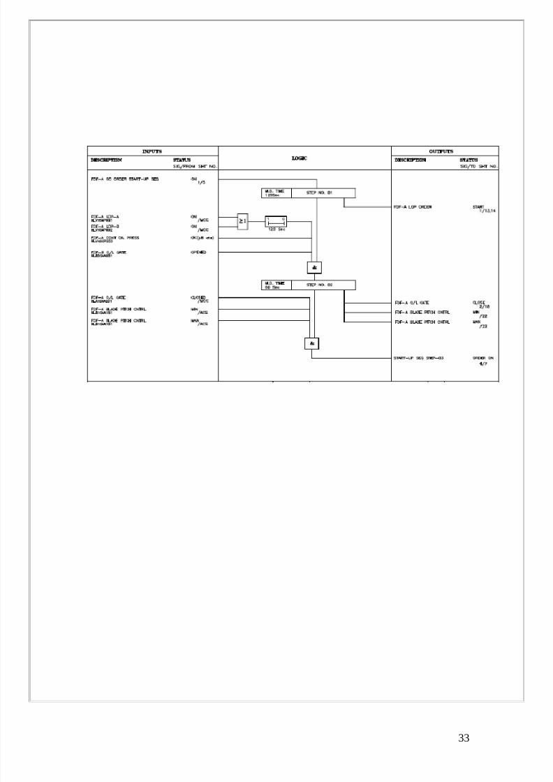
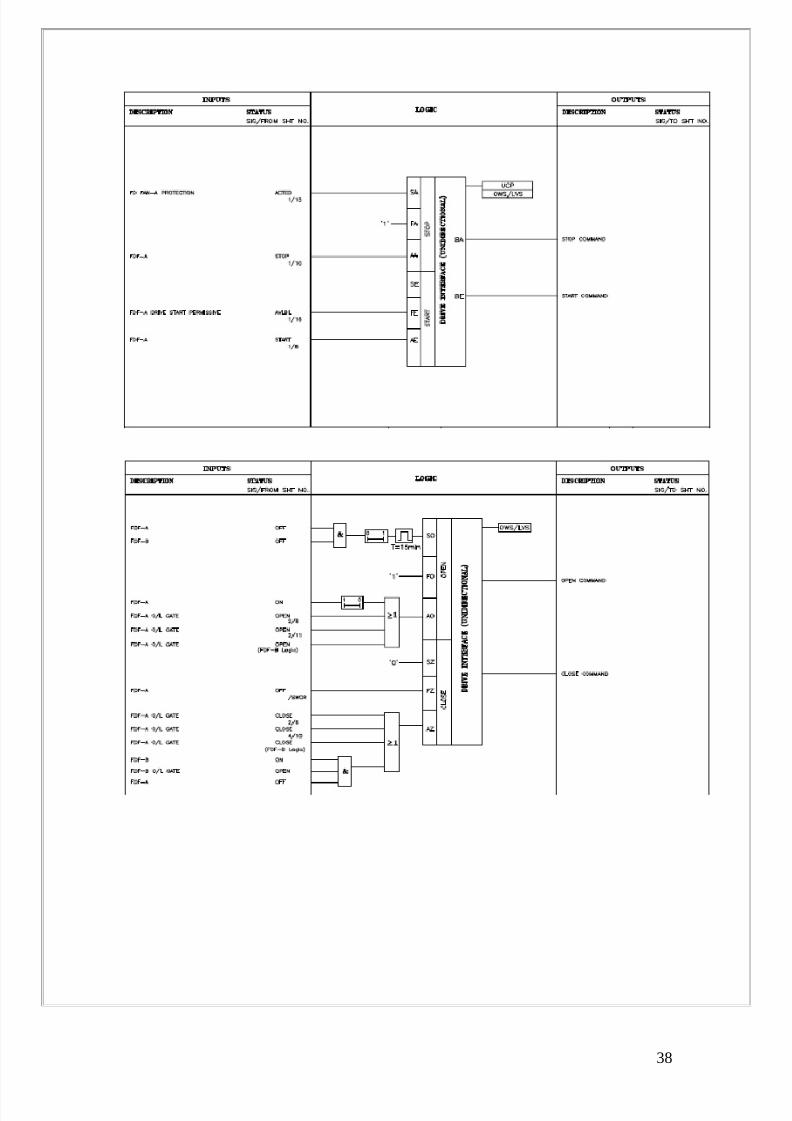
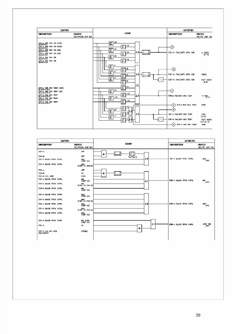
8.1.1 Sequence Control Scheme FD Fan A
31

8/4/2019 SA.SANTHOSH
http://slidepdf.com/reader/full/sasanthosh 31/41
32
8/4/2019 SA.SANTHOSH
http://slidepdf.com/reader/full/sasanthosh 32/41
33

8/4/2019 SA.SANTHOSH
http://slidepdf.com/reader/full/sasanthosh 33/41
34

8/4/2019 SA.SANTHOSH
http://slidepdf.com/reader/full/sasanthosh 34/41
35

8/4/2019 SA.SANTHOSH
http://slidepdf.com/reader/full/sasanthosh 35/41
36

8/4/2019 SA.SANTHOSH
http://slidepdf.com/reader/full/sasanthosh 36/41
37
8/4/2019 SA.SANTHOSH
http://slidepdf.com/reader/full/sasanthosh 37/41
38
8/4/2019 SA.SANTHOSH
http://slidepdf.com/reader/full/sasanthosh 38/41
39

8/4/2019 SA.SANTHOSH
http://slidepdf.com/reader/full/sasanthosh 39/41
P&ID Air & Flue gas path
40

8/4/2019 SA.SANTHOSH
http://slidepdf.com/reader/full/sasanthosh 40/41
CONCLUSION
Power plant control system is the nucleus of a power plant operation.
The reduction of operating time through the management of daily and
periodic operation, improvement and ease of maintenance, and improved
efficiency while reassuring reliability and safety are all merits of power
plant control systems.
Project Engineering Management, being the core engineering division for
design of power plant is a great platform to start the process of learningabout the power industry and the technical aspect of power plants. This
division is a hub of learning and engineering activity which enables
overall understanding and provides a summate view of a power plant.
Being part of Control & Instrumentation has enabled me to get an overall
picture of the power plant functioning and management. C&I engineering
touches almost all parts of a power plant and this makes the area of work
very vast and interesting. Power plant automation has become a very
challenging and dynamic field.
Advanced communication networks have helped the growth of power
plant automation in a phenomenal manner. The speed with which signals
flow between processors in control room and various distributed control
locations in power plant has made it possible to automate almost the
entire power plant. The advancement in the technology of transmitter and
valve actuators has simplified the overall power plant control system.
State of the art automation and control systems guarantee the simple and
the safe operation of steam power plant. The overall control of the plant
takes care of operational regulations as well as the primary systems. This
requires an integrated control of these parts. All process signals should be
managed without multiple engineering. In order to allow an easy future
expansion, the local and remote communication of the system has to be
based on modular technology.
41

8/4/2019 SA.SANTHOSH
http://slidepdf.com/reader/full/sasanthosh 41/41
In the changing social scenario, continuous demand of power has made
longer down time of power plant impossible. This in turn has made the
job of power plant automation very demanding. The failures of
equipments have to be either prevented or be reported immediately. This
all is leading to a rise in the challenges of power plant automation.
The challenge is not only towards the automation of new plants but there
is an additional challenge to modernize the control system of the existing
plants.