satellite link design - wordpress.com · in satellite communications, three factors influence...
TRANSCRIPT

SATELLITE LINK DESIGN
Dr. Marwah Ahmed Networks and
Communication
Department
1

Outlines
26-May-16 Networks and Communication Department
2
Introduction
Basic Transmission Theory
System Noise Temperature and G/T Ratio
Design of Downlinks
Satellite Communication Link Budget
Introduction
26-May-16 Networks and Communication Department
3
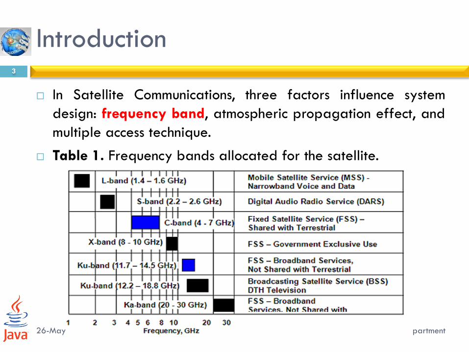
In Satellite Communications, three factors influence system
design: frequency band, atmospheric propagation effect, and
multiple access technique.
Table 1. Frequency bands allocated for the satellite.
Satellite Communications, 2/E by
Timothy Pratt, Charles Bostian, &
Jeremy Allnutt
Copyright © 2003 John Wiley & Sons.
Inc. All rights reserved.
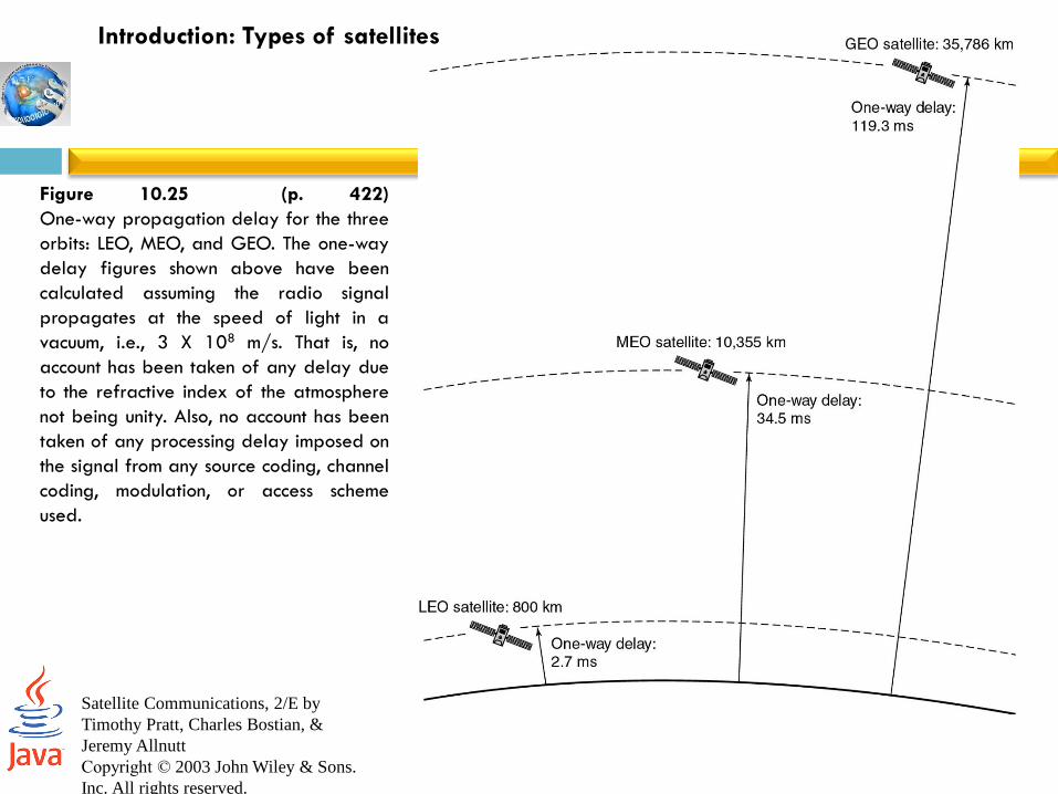
Figure 10.25 (p. 422)
One-way propagation delay for the three
orbits: LEO, MEO, and GEO. The one-way
delay figures shown above have been
calculated assuming the radio signal
propagates at the speed of light in a
vacuum, i.e., 3 X 10⁸ m/s. That is, no
account has been taken of any delay due
to the refractive index of the atmosphere
not being unity. Also, no account has been
taken of any processing delay imposed on
the signal from any source coding, channel
coding, modulation, or access scheme
used.
Introduction: Types of satellites
26-May-16 Networks and Communication Department
5
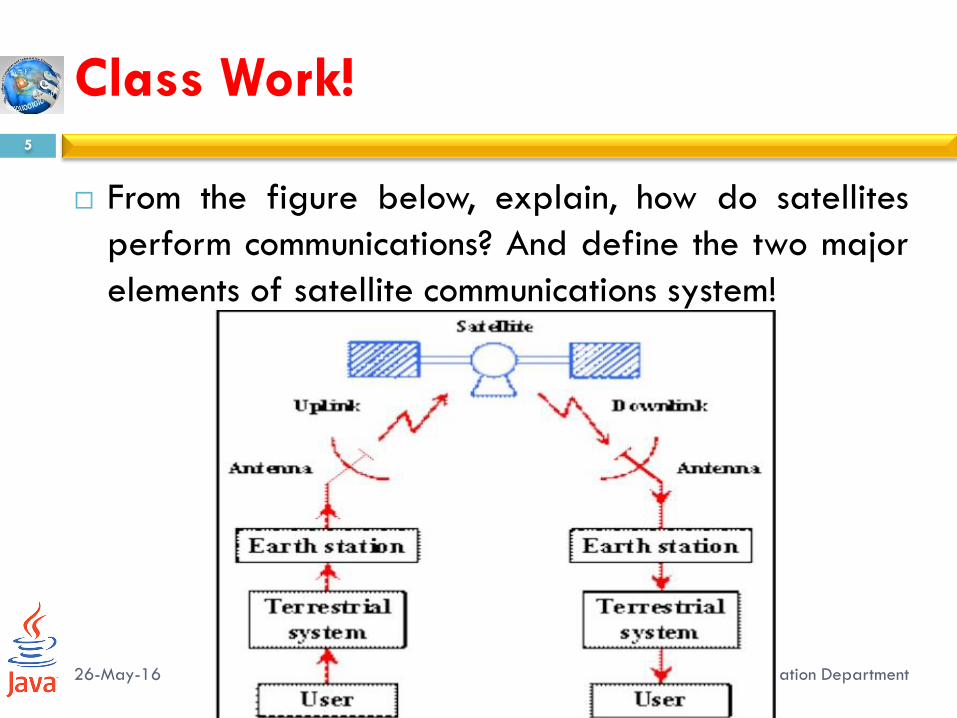
From the figure below, explain, how do satellites
perform communications? And define the two major
elements of satellite communications system!
Class Work!

Basic Transmission Theory
26-May-16
6
Networks and Communication Department
Basic Transmission Theory
26-May-16 Networks and Communication Department
7
The calculation of the power received by an earth
station from a satellite transmitter is fundamental to
the understanding of satellite communications.
Consider a transmitting source, in free space,
radiating a total power 𝑃𝑡 watts uniformly in all
directions as shown in Figure 4.2.

Satellite Communications, 2/E by
Timothy Pratt, Charles Bostian, &
Jeremy Allnutt
Copyright © 2003 John Wiley & Sons.
Inc. All rights reserved.
Figure 4.2 (p. 101)
Flux density produced by
an isotropic source.

26-May-16 Networks and Communication Department
9
At a distance 𝑅 meters from the hypothetical
isotropic source transmitting RF power 𝑃𝑡 watts, flux
density crossing the surface of a sphere with radius
𝑅 is given by:
𝐹 = 𝑃𝑡
4𝜋𝑅2 𝑊 𝑚2
Basic Transmission Theory
26-May-16 Networks and Communication Department
10
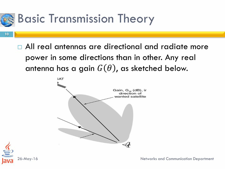
All real antennas are directional and radiate more
power in some directions than in other. Any real
antenna has a gain 𝐺 𝜃 , as sketched below.
Basic Transmission Theory

26-May-16 Networks and Communication Department
11
For a transmitter with output 𝑃𝑡 watts driving a
lossless antenna with gain 𝐺𝑡, the flux density in the
direction of the antenna boresight at distance 𝑅
meter is:
𝐹 = 𝑃𝑡𝐺𝑡4𝜋𝑅2
The product 𝑃𝑡𝐺𝑡 is often called the effective
isotopically radiated power or EIRP
Basic Transmission Theory
Satellite Communications, 2/E by
Timothy Pratt, Charles Bostian, &
Jeremy Allnutt
Copyright © 2003 John Wiley & Sons.
Inc. All rights reserved.
Figure 4.3 (p. 102)

26-May-16 Networks and Communication Department
13
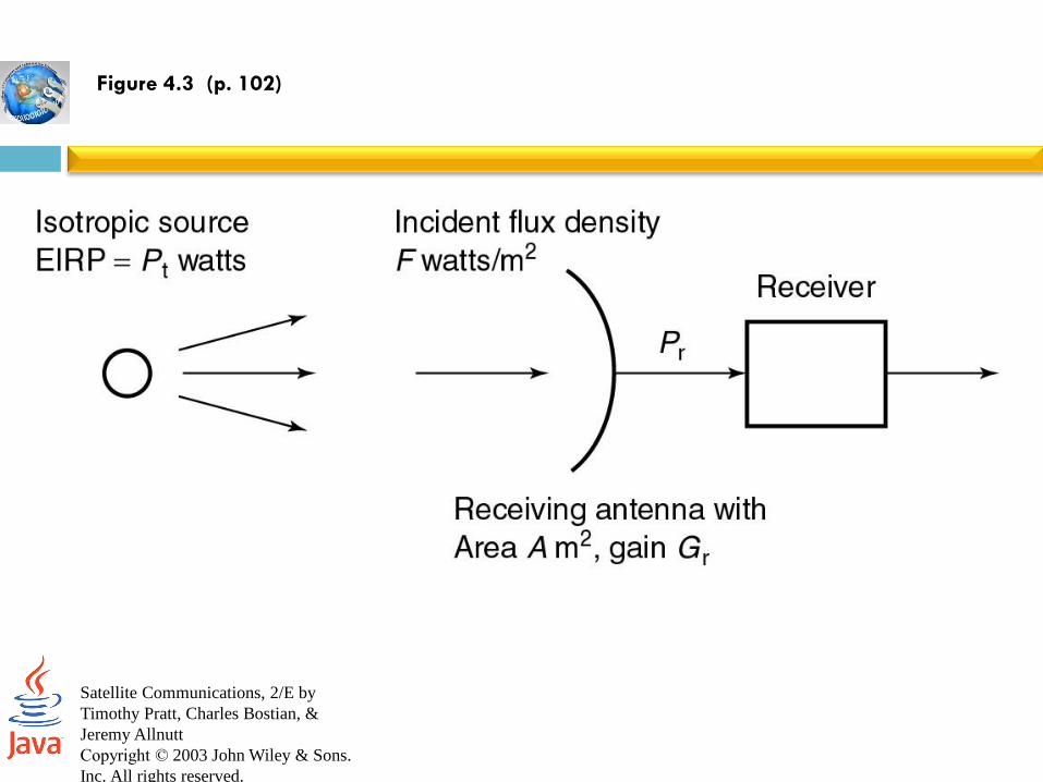
If we had an ideal receiving antenna with an aperture area of 𝐴 𝑚2, as shown in Figure 4.3, we will collect power 𝑃𝑟 watts given by:
𝑃𝑟 = 𝐹 × 𝐴 watts
A practical antenna with a physical aperture area of 𝐴𝑟 𝑚
2 will not deliver the power transmitted, and some is absorbed by lossy components. This reduction in efficiency is described by using an effective aperture 𝐴𝑒 where:
𝐴𝑒 = 𝜂𝐴 𝐴𝑟
And 𝜂𝐴 is the aperture efficiency of the antenna.
Basic Transmission Theory
26-May-16 Networks and Communication Department
14
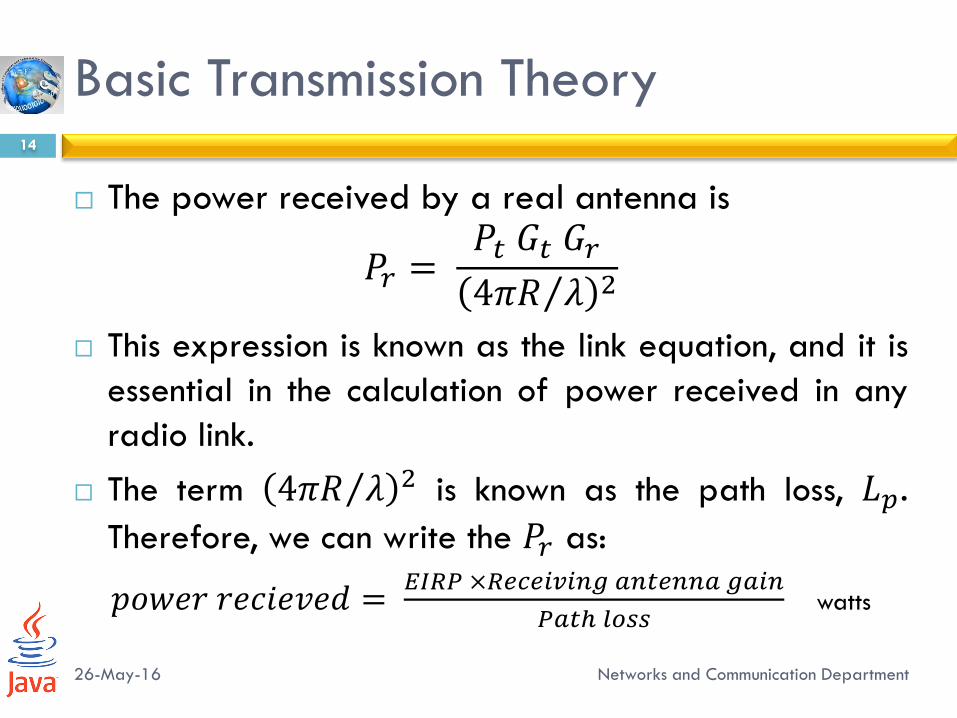
The power received by a real antenna is
𝑃𝑟 = 𝑃𝑡 𝐺𝑡 𝐺𝑟4𝜋𝑅 𝜆 2
This expression is known as the link equation, and it is
essential in the calculation of power received in any
radio link.
The term 4𝜋𝑅 𝜆 2 is known as the path loss, 𝐿𝑝.
Therefore, we can write the 𝑃𝑟 as:
𝑝𝑜𝑤𝑒𝑟 𝑟𝑒𝑐𝑖𝑒𝑣𝑒𝑑 = 𝐸𝐼𝑅𝑃 ×𝑅𝑒𝑐𝑒𝑖𝑣𝑖𝑛𝑔 𝑎𝑛𝑡𝑒𝑛𝑛𝑎 𝑔𝑎𝑖𝑛
𝑃𝑎𝑡ℎ 𝑙𝑜𝑠𝑠 watts
Basic Transmission Theory

26-May-16 Networks and Communication Department
15
In Communication systems, decibel quantities are commonly
used to simplify calculations:
𝑃𝑟 = 𝐸𝐼𝑅𝑃 + 𝐺𝑟 − 𝐿𝑝 dBW
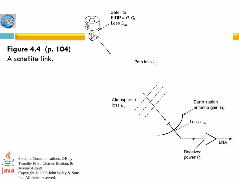
In practice, we will need to take account of more complex
situation in which we have losses in the atmosphere due to
attenuation by oxygen, water vapor, and rain, losses in the
antennas at each end of the link.
𝑃𝑟 = 𝐸𝐼𝑅𝑃 + 𝐺𝑟 − 𝐿𝑝 − 𝐿𝑎 − 𝐿𝑡𝑎 − 𝐿𝑟𝑎 dBW
where 𝐿𝑎 is the attenuation in the atmosphere, and 𝐿𝑡𝑎 , 𝐿𝑟𝑎 are
the losses associated with the transmitting and receiving,
respectively.
Basic Transmission Theory
Satellite Communications, 2/E by
Timothy Pratt, Charles Bostian, &
Jeremy Allnutt
Copyright © 2003 John Wiley & Sons.
Inc. All rights reserved.
Figure 4.4 (p. 104)
A satellite link.
System Noise Temperature and G/T
26-May-16
17
Networks and Communication Department

26-May-16 Networks and Communication Department
18
Is a useful concept in communications receivers, since it provides a way to determining how much thermal noise is generated by active and passive devices in the receiving system.
The noise power is given by:
𝑃𝑛 = 𝑘𝑇𝑠 𝐵𝑛
where 𝑘 denotes Boltzman’s constant = 1.39× 10⁻²³ J/K = -228.6 dB W/K/Hz, 𝑇𝑠 is the system noise temperature of source in kelvin degrees, and 𝐵𝑛 represents the noise bandwidth in which the noise power is measured, in Hz
Noise Temperature

Research Work!
26-May-16 Networks and Communication Department
19
Calculate the total noise power at the output of the
IF amplifier of the receiver in the below figure.

G/T Ratio for Earth Stations
26-May-16 Networks and Communication Department
20
The link equation can be rewritten in terms of 𝐶𝑁 at the
earth station:
𝐶
𝑁=
𝑃𝑡𝐺𝑡𝐺𝑟𝑘𝑇𝑠 𝐵𝑛
𝜆
4𝜋𝑅
2
= 𝑃𝑡𝐺𝑡𝑘 𝐵𝑛
𝜆
4𝜋𝑅
2𝐺𝑟𝑇𝑠
Thus, 𝐶 𝑁 ∝ 𝐺𝑟 𝑇𝑠 , and can be used to specify the quality of a
receiving earth station or a satellite receiving system.

Design of Downlink
26-May-16
21
Networks and Communication Department
Design of Downlinks
The design of any satellite communication is based on meeting a minimum C/N ratio for a specified percentage of time.
Any satellite link can be designed with very large antenna to achieve high C/N ratios under all conditions, but cost will be high.
The art of good system design is to reach the best compromise of system parameters that meet the specification at the lowest cost.
For example if a satellite link is designed with sufficient margin to overcome a 20 dB rain fade rather than a 3 dB fade, earth station antennas with seven times the diameter are required.

Design of Downlinks
All satellite communication links are affected by rain
attenuation.
In the 6/4 GHz band the effect of rain on the link is small
In the 14/11GHz (Ku) band and even more in the 30/20 GHz
(Ka) band, rain attenuation becomes important.
Rain attenuation is very variable phenomenon, both with time
and place.

Link Budget
26-May-16
24
Networks and Communication Department
Link Budgets
C/N is simplified by the used of link budget
A link budget is a tabular method for evaluating the received
power and noise power in a radio link.
Link budget must be calculated for an individual transponder,
and must be repeated for each of the individual links.
Link budgets are usually calculated for the worst case, the one
in which the link will have the lowest C/N ratio.
Link Budgets
Factors which contribute to a worst case scenario include: an
earth station located at the edge of the satellite coverage
zone where the received signal is typically 3 dB lower than the
center of the zone.
This is because the satellite antenna pattern, maximum path
length from the satellite to the earth station, low elevation
angle at the earth station giving the highest atmospheric path
attenuation in clear air and maximum rain attenuation on the
link causing loss of received signal power and increase in
receiving system noise temperature.
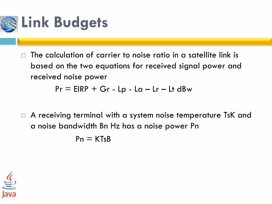
Link Budgets
The calculation of carrier to noise ratio in a satellite link is
based on the two equations for received signal power and
received noise power
Pr = EIRP + Gr - Lp - La – Lr – Lt dBw
A receiving terminal with a system noise temperature TsK and
a noise bandwidth Bn Hz has a noise power Pn
Pn = KTsB
Q & A
26-May-16
28
Networks and Communication Department