satisfying non-functional requirements in model … university licentiate thesis¨ no.150 satisfying...
TRANSCRIPT

Malardalen University Licentiate ThesisNo.150
Satisfying Non-FunctionalRequirements in Model-Driven
Development of Real-TimeEmbedded Systems
Mehrdad Saadatmand
May 2012
School of Innovation, Design and EngineeringMalardalen University
Vasteras, Sweden

Copyright c©Mehrdad Saadatmand, 2012ISSN 1651-9256ISBN 978-91-7485-066-6Printed by Arkitektkopia, Vasteras, SwedenDistribution: Malardalen University Press

Abstract
Design of real-time embedded systems is a complex and challenging task. Partof this complexity originates from their limited resources which incurs han-dling a big range of Non-Functional Requirements (NFRs). Therefore, sat-isfaction of NFRs plays an important role in the correctness of the design ofthese systems. Model-driven development has the potential to reduce the de-sign complexity of real-time embedded systems by increasing the abstractionlevel, enabling analysis at earlier phases of development and code generation.In this thesis, we identify some of the challenges that exist in model-driven de-velopment of real-time embedded systems with respect to NFRs, and providetechniques and solutions that aim to help with the satisfaction of NFRs. Ourend goal is to ensure that the set of NFRs defined for a system is not violatedat runtime.
First, we identify and highlight the challenges of modeling NFRs intelecommunication systems and discuss the application of a UML-based ap-proach for modeling them. Since NFRs have dependencies, and the design de-cisions to satisfy them cannot be considered in isolation, we propose a model-based approach for trade-off analysis of NFRs. The approach enables the com-parison of different design models with respect to the satisfaction level of theirNFRs. Following the issue of evaluating the interdependencies of NFRs, wealso propose solutions for establishing and maintaining balance between differ-ent NFRs. In this regard, we categorize our suggested solutions into static anddynamic methods. The former refers to a static design and set of features whichensures and guarantees (by construction) the balance of NFRs, while the lattermeans establishing balance at runtime by reconfiguring the system and runtimeadaptation. Finally, we discuss the role of the execution platform in preserva-tion and monitoring of timing properties in real-time embedded systems andpropose an approach to enrich the platform with necessary mechanisms formonitoring them.
i


To my parents...


Acknowledgments
I would like to start by thanking and appreciating the work of all the peopleat IDT department for making it a very friendly and cooperative research andeducational environment which I believe can serve as a role model for otherinstitutes.
Many special thanks to my main supervisor, Mikael Sjodin, who has beenvery supportive and encouraging beyond just academical work and also to myassistant supervisors Antonio Cicchetti and Radu Dobrin for all their guidance.Working with you all is a great pleasure.
Thanks to Per Wolde who has been a great friend of mine since the veryfirst days that I came to Sweden and his support for me to start this work. Tomy office mates, Federico and again Antonio, with whom I have had greatmemories especially from all the travels that we had together; thank you.
I would like to also thank my managers and colleagues at Enea & Xdin:Barbro Claesson, Erik Netz, Anders Tornqvist, Thomas Barna, Celi, MathiasL., Daniel B., Joel H., Detlef; also all the great people at IDT whose acquain-tance I treasure: Barbara, Farhang, Moris, Saad, Rafia, Asa, Gunnar, Malin,Monika, Carola, Ingrid, Susanne, Andreas J., Thomas N., Ivica, Dag, Gordana,Jan C., Jan G., Hans, Frank L., Paul, Cristina S., Kristina L., Mats, Bjorn, Lars,Adnan, Aida, Aneta, Severine, Nima, Jagadish, Yue Lue, Thomas L., Etienne,Mikael A., Juraj, Josip, Ana, Luka, Leo, Huseyin , Hongyu, Kivanc, AndreasG., Daniel, Sasi, Sara, Stefan, Abhilash...
A very special thanks to Nazanin for being by my side with her positivespirit; my life in Sweden would have not been the same without you.
My deepest gratitudes to my family who have always been there for me nomatter what. Without them I could have never reached this far.
Mehrdad SaadatmandVasteras, May, 2012
v


List of Publications
Papers Included in the Licentiate Thesis 1 2
Paper A UML-Based Modeling of Non-Functional Requirements in Telecom-munication Systems. Mehrdad Saadatmand, Antonio Cicchetti andMikael Sjodin. The Sixth International Conference on Software Engi-neering Advances (ICSEA 2011), Barcelona, Spain, October, 2011.
Paper B Modeling and Trade-off Analysis of NFRs. Mehrdad Saadatmand,Antonio Cicchetti and Mikael Sjodin. MRTC report ISSN 1404-3041ISRN MDH-MRTC-267/2012-1-SE, Malardalen Real-Time ResearchCentre, Malardalen University, April, 2012. 3
Paper C Modeling Security Aspects in Distributed Real-Time Component-Based Embedded Systems. Mehrdad Saadatmand and Thomas Leveque.The Ninth International Conference on Information Technology : NewGenerations (ITNG), Las Vegas, Nevada, USA, April, 2012.
Paper D Design of Adaptive Security Mechanisms for Real-Time EmbeddedSystems. Mehrdad Saadatmand, Antonio Cicchetti and Mikael Sjodin.The Fourth International Symposium on Engineering Secure Softwareand Systems (ESSoS), Eindhoven, The Netherlands, February, 2012.
Paper E The Role of Schedulers in Model-Driven Development of Real-Time Systems. Mehrdad Saadatmand, Mikael Sjodin and Naveed Ul
1A licentiate degree is a Swedish graduate degree halfway between M.Sc. and Ph.D.2The included articles have been reformatted to comply with the licentiate layout.3Under submission for conference publication. Also partially published as a WiP paper in
the Sixteenth IEEE International Conference on Emerging Technology & Factory Automation(ETFA11), Toulouse, France, September, 2011.
vii

viii
Mustafa. MRTC report ISSN 1404-3041 ISRN MDH-MRTC-264/2012-1-SE, Malardalen Real-Time Research Centre, Malardalen University,March, 2012.

ix
Additional Papers, Not Included in the LicentiateThesis• On Generating Security Implementations from Models of Embedded Sys-
tems. Mehrdad Saadatmand, Antonio Cicchetti and Mikael Sjodin. TheSixth International Conference on Software Engineering Advances (IC-SEA 2011), Barcelona, Spain, October, 2011.
• Enabling Trade-off Analysis of NFRs on Models of Embedded Systems.Mehrdad Saadatmand, Antonio Cicchetti and Mikael Sjodin. The Six-teenth IEEE International Conference on Emerging Technology & Fac-tory Automation (ETFA11), WiP session, Toulouse, France, September,2011.
• A Methodology for Designing Energy-aware Secure Embedded Sys-tems. Mehrdad Saadatmand, Antonio Cicchetti and Mikael Sjodin. TheSixth IEEE International Symposium on Industrial Embedded Systems(SIES11), Vasteras, Sweden, June, 2011.
• Toward a Tailored Modeling of Non-Functional Requirements forTelecommunication Systems. Mehrdad Saadatmand, Antonio Cicchettiand Mikael Sjodin. The Eighth International Conference on InformationTechnology : New Generations (ITNG), Las Vegas, USA, April, 2011.
• On the Need for Extending MARTE with Security Concepts. MehrdadSaadatmand, Antonio Cicchetti and Mikael Sjodin. The Second Interna-tional Workshop on Model Based Engineering for Embedded SystemsDesign (M-BED 2011), Grenoble, France, March, 2011.


Contents
I Thesis 1
1 Introduction 31.1 Basic Terms and Definitions . . . . . . . . . . . . . . . . . . 31.2 Background and Motivation . . . . . . . . . . . . . . . . . . 61.3 Problems and Contributions Overview . . . . . . . . . . . . . 71.4 Thesis Outline . . . . . . . . . . . . . . . . . . . . . . . . . . 8
2 Research Overview 112.1 Research Goals . . . . . . . . . . . . . . . . . . . . . . . . . 122.2 Research Contributions . . . . . . . . . . . . . . . . . . . . . 162.3 Research Methodology . . . . . . . . . . . . . . . . . . . . . 18
3 Conclusions 213.1 Future Work . . . . . . . . . . . . . . . . . . . . . . . . . . . 22
Bibliography 25
II Included Papers 27
4 Paper A:UML-Based Modeling of Non-Functional Requirements inTelecommunication Systems 294.1 Introduction . . . . . . . . . . . . . . . . . . . . . . . . . . . 314.2 Motivations . . . . . . . . . . . . . . . . . . . . . . . . . . . 33
4.2.1 Telecommunication Systems . . . . . . . . . . . . . . 334.2.2 Problems with Non-Functional Requirements . . . . . 34
4.3 Related Work . . . . . . . . . . . . . . . . . . . . . . . . . . 35
xi

xii Contents
4.4 Suggested UML profile . . . . . . . . . . . . . . . . . . . . . 374.4.1 Modeling Traceability Using SysML . . . . . . . . . 384.4.2 MARTE for Non-functional Requirements and Analy-
sis Support . . . . . . . . . . . . . . . . . . . . . . . 394.4.3 Covering Security Aspects . . . . . . . . . . . . . . . 40
4.5 Modeling a Security Requirement Using the Suggested Profile 414.6 Discussion . . . . . . . . . . . . . . . . . . . . . . . . . . . . 434.7 Conclusion and Future Work . . . . . . . . . . . . . . . . . . 45Bibliography . . . . . . . . . . . . . . . . . . . . . . . . . . . . . 47
5 Paper B:Modeling and Trade-off Analysis of NFRs 515.1 Introduction . . . . . . . . . . . . . . . . . . . . . . . . . . . 535.2 Non-Functional Requirements . . . . . . . . . . . . . . . . . 555.3 Characteristics of the Solutions . . . . . . . . . . . . . . . . . 575.4 Suggested Profile . . . . . . . . . . . . . . . . . . . . . . . . 585.5 Implementation and Usage Example . . . . . . . . . . . . . . 615.6 Related Work . . . . . . . . . . . . . . . . . . . . . . . . . . 655.7 Conclusion and Future work . . . . . . . . . . . . . . . . . . 675.8 Acknowledgements . . . . . . . . . . . . . . . . . . . . . . . 68Bibliography . . . . . . . . . . . . . . . . . . . . . . . . . . . . . 69
6 Paper C:Modeling Security Aspects in Distributed Real-Time Component-Based Embedded Systems 736.1 Introduction . . . . . . . . . . . . . . . . . . . . . . . . . . . 756.2 Motivations . . . . . . . . . . . . . . . . . . . . . . . . . . . 766.3 Automatic Payment System . . . . . . . . . . . . . . . . . . . 776.4 Approach . . . . . . . . . . . . . . . . . . . . . . . . . . . . 79
6.4.1 General Approach . . . . . . . . . . . . . . . . . . . 796.4.2 ProCom Component Model . . . . . . . . . . . . . . 806.4.3 Data Model . . . . . . . . . . . . . . . . . . . . . . . 826.4.4 Physical Platform And Deployment Modeling . . . . . 846.4.5 Security Properties . . . . . . . . . . . . . . . . . . . 856.4.6 Cost of Security Implementations . . . . . . . . . . . 876.4.7 Security Implementation Strategy . . . . . . . . . . . 886.4.8 Transformation . . . . . . . . . . . . . . . . . . . . . 89
6.5 Implementation . . . . . . . . . . . . . . . . . . . . . . . . . 916.6 Related Work . . . . . . . . . . . . . . . . . . . . . . . . . . 92

Contents xiii
6.7 Conclusion . . . . . . . . . . . . . . . . . . . . . . . . . . . 94Bibliography . . . . . . . . . . . . . . . . . . . . . . . . . . . . . 95
7 Paper D:Design of Adaptive Security Mechanisms for Real-Time EmbeddedSystems 997.1 Introduction . . . . . . . . . . . . . . . . . . . . . . . . . . . 1017.2 Background and Motivation . . . . . . . . . . . . . . . . . . 1027.3 Approach . . . . . . . . . . . . . . . . . . . . . . . . . . . . 103
7.3.1 Log Information and Adaptation Mechanism . . . . . 1057.3.2 Implementation Details . . . . . . . . . . . . . . . . . 1077.3.3 Evaluation . . . . . . . . . . . . . . . . . . . . . . . 108
7.4 Discussion . . . . . . . . . . . . . . . . . . . . . . . . . . . . 1117.5 Related Work . . . . . . . . . . . . . . . . . . . . . . . . . . 1127.6 Conclusion and Future Work . . . . . . . . . . . . . . . . . . 114Bibliography . . . . . . . . . . . . . . . . . . . . . . . . . . . . . 115
8 Paper E:The Role of Schedulers in Model-Driven Development of Real-Time Systems 1198.1 Introduction . . . . . . . . . . . . . . . . . . . . . . . . . . . 1218.2 Background and Motivation . . . . . . . . . . . . . . . . . . 122
8.2.1 CHESS Project . . . . . . . . . . . . . . . . . . . . . 1228.2.2 OSE Real-Time Operating System . . . . . . . . . . . 1248.2.3 Goal . . . . . . . . . . . . . . . . . . . . . . . . . . . 125
8.3 Scheduler Design and Implementation . . . . . . . . . . . . . 1268.3.1 System Components . . . . . . . . . . . . . . . . . . 1298.3.2 Signals and Communications . . . . . . . . . . . . . . 1318.3.3 Priority Assignment . . . . . . . . . . . . . . . . . . 1328.3.4 Scheduling of Tasks . . . . . . . . . . . . . . . . . . 1328.3.5 Monitoring of Tasks . . . . . . . . . . . . . . . . . . 135
8.4 Experiment and Monitoring Results . . . . . . . . . . . . . . 1368.5 Related Work . . . . . . . . . . . . . . . . . . . . . . . . . . 1418.6 Discussion and Conclusion . . . . . . . . . . . . . . . . . . . 1438.7 Acknowledgements . . . . . . . . . . . . . . . . . . . . . . . 144Bibliography . . . . . . . . . . . . . . . . . . . . . . . . . . . . . 145


I
Thesis
1


Chapter 1
Introduction
The main goal in the design of a software system is to deliver a product whichsatisfies all the requirements of different stakeholders. Requirements are gen-erally categorized into functional and non-functional. Although non-functionalrequirements usually receive less attention in the design of many types of sys-tems (for example in desktop applications) they play an important role in cer-tain domains; particularly, real-time embedded systems. Satisfaction of non-functional requirements, such as timing, is critical in these systems and candetermine the success or failure of the final product. In this thesis, we look atdifferent challenges of satisfying non-functional requirements within the con-text of model-driven development of real-time embedded systems. In our workwhich extends from the system model down to the execution platform, we pro-pose solutions and methods that help to better satisfy non-functional require-ments.
1.1 Basic Terms and Definitions
In this section, we provide definitions for some of the key terms that are usedthroughout the thesis.
We consider two categories of requirements: functional and non-functional. In the simplest form, functional requirements are those which de-fine what the system should do, while the term non-functional requirementis used for requirements which specify how a system should perform, or assuggested in [1] ”a non-functional requirement is an attribute of or a con-
3

4 Chapter 1. Introduction
straint on a system”. There is a big number of suggested definitions for non-functional requirements which are discussed in [2]. These requirements areusually described with terms that end with ’ility’ such as availability, ’ity’ suchas atomicity while a few other ones such as performance and user-friendlinessdo not follow this pattern. According to the IEEE standards, 610.12-1990 andISO/IEC/IEEE 24765:2010(E) [3, 4], the following definitions are providedfor requirement, functional and non-functional requirement, and also derivedrequirement:
• Requirement:
1. a condition or capability needed by a user to solve a problem orachieve an objective.
2. a condition or capability that must be met or possessed by a system,system component, product, or service to satisfy an agreement,standard, specification, or other formally imposed documents.
3. a documented representation of a condition or capability as in (1)or (2).
4. a condition or capability that must be met or possessed by a sys-tem, product, service, result, or component to satisfy a contract,standard, specification, or other formally imposed document.
• Functional Requirement:
1. a statement that identifies what a product or process must accom-plish to produce required behavior and/or results.
2. a requirement that specifies a function that a system or system com-ponent must be able to perform.
• Non-Functional Requirement: a software requirement that describes notwhat the software will do but how the software will do it (i.e., designconstraints). Examples: software performance requirements, softwareexternal interface requirements, software design constraints, and soft-ware quality attributes. Non-functional requirements are sometimes dif-ficult to test, so they are usually evaluated subjectively.
• Derived Requirement:
1. a lower-level requirement that is determined to be necessary for atop-level requirement to be met.
1.1 Basic Terms and Definitions 5
2. a requirement that is not explicitly stated in customer requirements,but is inferred from contextual requirements (such as applicablestandards, laws, policies, common practices, and management de-cisions) or from requirements needed to specify a product or ser-vice component.
In this thesis, we use the term extra-functional as a synonym to non-functional, however, to be consistent with the style that is used in the literature,we use it as an adjective for properties as in the phrase ”extra-functional prop-erties”. This brings us to the next term which is property. It is defined in IEEEstandard ISO/IEC/IEEE 24765:2010(E) [3] as:
A responsibility that is an inherent or distinctive characteristic or traitthat manifests some aspect of an object’s knowledge or behavior (respon-sibility: A generalization of properties (attributes, participant properties,and operations) and constraints. An instance possesses knowledge, ex-hibits behavior, and obeys rules. These are collectively referred to as theinstances responsibilities. A class abstracts the responsibilities in com-mon to its instances. A responsibility may apply to each instance of theclass (instance-level) or to the class as a whole (class-level) [5]).
In this work, we distinguish between requirements and properties by con-sidering the former as an expression of a need (possibly informal), and the lat-ter as a statement that is usually asserted formally and can be therefore provenand analyzed (e.g., calculated response time of a component). This impliesthat ”a requirement can require that a certain property holds (e.g., absence ofdeadlock, meeting deadline, not overflowing a queue, etc.) and that in orderfor a property to hold a number of requirements may have to be met, which wenormally neither express nor assert formally”1.
Based on these definitions, we use the term satisfaction for requirementsand preservation for extra-functional properties (i.e., to keep properties withintheir acceptable and valid ranges and protect them from violation). Accord-ingly, ”response time of a component should not exceed 2ms” is a requirement,while ”response time of component A never exceeds 2ms” and ”response timeof component B is equal to 1ms” are expressions of properties in a system.
Balancing trade-offs among requirements can incur adjusting system prop-erties that are related to those requirements. Moreover, we consider a rela-tionship between an NFR and extra-functional properties of the system in thesense that, in order to satisfy an NFR, its related extra-functional properties
1These definitions have been provided and formulated with the help of Prof. Tullio Vardanega.

6 Chapter 1. Introduction
should have valid values. For example, to satisfy performance requirements ofa real-time system, execution and response time values (among others) shouldremain within a valid range. Moreover, a property per se does not tell muchabout its validity. Only when a property is considered along with its relatedNFR or NFRs, it becomes possible to evaluate whether it is valid for a spe-cific system and design or not. For example, a component with the worst-caseexecution time of 100ms can be acceptable in designing one system but thesame component can violate the requirements of another system and may notbe appropriate for it.
1.2 Background and Motivation
Embedded computer systems are systems that are designed to operate as partof other devices. These systems are usually designed for specific and dedicatedfunctions, and interact with their external environment through sensors and ac-tuators [6, 7]. This interaction often brings along real-time requirements. How-ever, besides real-time requirements, resource constraints in these systems alsointroduce other limitations with respect to properties such as energy consump-tion, performance, and safety. Due to resource constraints that these systemshave, the correct functionality of the whole system depends heavily on the sat-isfaction of its NFRs. On the other hand, NFRs are often interconnected andcannot be considered in isolation. An example of such interconnection and de-pendency can be observed more explicitly between security and performancerequirements in a system. Therefore, in satisfying a requirement, its impactson other requirements should also be taken into account, and trade-off analysisamong NFRs needs to be done [2, 8]. Handling a big range of requirements,establishing balance among them and performing trade-off analysis contributeto the high design complexity of real-time embedded systems and make it achallenging task [7].
Model-Driven Development (MDD) is a promising approach in raising ab-straction level and reducing design complexity of real-time embedded systems,which also enables analysis of the system at earlier phases of development.This helps with the identification of problems in the system design beforereaching the implementation phase [9, 10]. The implementation of the systemcan also be generated from the design models through a set of model transfor-mations. In this context, non-functional requirements are captured by expres-sion of extra-functional properties that are attached to model elements. In anintegrated model-driven and component-based approach, the model elements

1.3 Problems and Contributions Overview 7
that extra-functional properties are annotated on can be components.However, in order to ensure correctness of the generated system, it is im-
portant to ensure that in each step, extra-functional properties that are specifiedon the model are preserved. This means that for each transformation, inputproperties should be preserved in the output of the transformation. It also in-cludes the system execution at runtime which is the result of executing thegenerated source code. This implies that the execution platform should be ableto actively monitor and enforce extra-functional properties at runtime. To thisend, the execution platform also requires to be semantically aware of the spec-ified properties and related events in order to monitor them and detect theirprobable deviations.
1.3 Problems and Contributions Overview
There are several challenges in satisfying non-functional requirements usinga model-driven development method for real-time embedded systems. Thesechallenges include (but are not limited to) issues such as how to model NFRs,how to model their interdependencies, and also how to ensure that the imple-mentation that is generated from the model behaves as expected during execu-tion and not in a way that impairs the satisfactions of NFRs at runtime.
As the first step, we introduce an approach using Unified Modeling Lan-guage (UML) for modeling non-functional requirements and extra-functionalproperties in telecommunication systems (as an example and sub-domain ofreal-time embedded systems). It is done by suggesting adoption from andcombining several already existing UML-based languages. In satisfying anNFR, its impacts on other NFRs should also be taken into account. To enablemodel-based trade-off analysis of NFRs, we propose a UML profile for model-ing dependencies and impacts of NFRs and functional parts that contribute tothe satisfaction of each NFR in a positive or negative way. The concepts thatare provided in this UML profile are based on the Soft-goal InterdependencyGraph (SIG) approach that is used in the NFR Framework [11].
As an example of interdependency of NFRs, we consider security and tim-ing requirements in real-time embedded systems. To satisfy security require-ments certain mechanisms, such as encryption, should be applied. However,adding such security mechanisms may result in the violation of the timing re-quirements of the system. In the context of an integrated model-driven andcomponent-based approach, we propose an approach to automatically derivethe component model of a system that includes components implementing se-

8 Chapter 1. Introduction
curity mechanisms (from an original component model without security com-ponents). This is done by identifying and annotating sensitive data flows in themodel. The derived component model uses the same meta-model as the orig-inal model, and therefore, enables using the same timing analysis applicableto the original model. This way, timing impacts of added security componentscan be analyzed at earlier phases and before the implementation phase.
Modeling NFRs and including them along with functional elements, andanalyzing the model do not guarantee that the system that is generated fromthe model is capable of satisfying those NFRs. Violations in this respect cannot only happen during transformations to generate intermediate models andfinally code, but also during execution of the generated code on the platform.To mitigate such violations, extra-functional properties of the system can beenforced and monitored during runtime. Upon detection of such violations,adaptation and reconfiguration of the system may be performed as a counter-active measure. We have developed an adaptive approach for balancing the se-curity level of a system with its timing requirements at runtime. The approachis based on keeping a history of the timing behaviors of encryption algorithmsand using a weaker but less time-consuming one when a timing violation oc-curs. The introduced adaptation mechanism is suitable for complex real-timesystems where timing analysis is not practical or not much information abouttiming characteristics of each individual task is available.
On the other hand, in order to monitor and detect violation of extra-functional properties at runtime, the execution platform should have certaincapabilities. We discuss these capabilities for timing requirements which areof great importance in real-time embedded systems. We also introduce theconcept of second-layer scheduler for monitoring of real-time events, such asdeadline misses and execution time overruns, on top of a real-time operatingsystem with a priority-based preemptive scheduling policy to provide such ca-pabilities.
1.4 Thesis Outline
The thesis is organized into two parts:Part I includes three chapters. Chapter 1 provided an introduction to the thesisand formulated the research problem. In Chapter 2, the research overviewdescribing detailed research goals and contributions is offered. In Chapter 3we summarize the work and present suggestions for the future work.Part II presents the technical contributions of the thesis in detail in the form of

1.4 Thesis Outline 9
research papers which are organized in Chapters 4-8.


Chapter 2
Research Overview
In this thesis, we target some of the challenges related to the satisfaction ofnon-functional requirements in the context of model-driven development ofreal-time embedded systems. Towards this goal, we also discuss techniquesthat help with the preservation of extra-functional properties in these systemsand mitigate their deviations from the desired behavior. The importance ofthis research objective becomes more obvious and is motivated considering thefollowing points:
• Satisfaction of non-functional requirements is important in the design ofreal-time embedded systems. A system design which cannot satisfy itsnon-functional requirements (e.g., timing requirements) can mean failureof the end product.
• The non-functional requirements are mapped to architectural models andcaptured by extra-functional properties.
• Analysis is performed on models of embedded systems in order to cal-culate extra-functional properties of the system and its components,such as response time, and to evaluate satisfaction feasibility of its non-functional requirements. Analyses are based on some assumptions andpreconditions. Violation of these assumptions equals to the violation andinvalidation of the analysis results.
• At runtime, several factors such as transient loads, difference betweenthe ideal execution environment (taken into account for analysis) and the
11

12 Chapter 2. Research Overview
actual one, can lead to violation of the assumptions that were used toperform analysis [12].
• It may not be practical and/or economical to perform analysis on all typesof extra-functional properties. In such cases, runtime monitoring andhandling of violations can be used to preserve extra-functional proper-ties.
In this context, the term preserve that we use in our work implies and isbased on the assumption that there is some knowledge about valid and invalidvalues (e.g., range of values) that an extra-functional property can have in aspecific design.
Satisfaction of non-functional requirements in real-time embedded systemshas been considered in this thesis in the context of model-driven developmentand particularly Model-Driven Architecture (MDA) methodology that is sug-gested by Object Management Group (OMG) [13]. UML is the key modelinglanguage at the heart of MDA. Figure 2.1 depicts the MDA design flow thatdefines the development context of this thesis.
As shown in figure 2.1, different types of analyses are performed at differ-ent levels throughout the transformation chain for code generation to ensurecorrectness of the design. The idea here is to provide a read-only Platform-Specific Model (PSM) to the user, and also make the manual editing of the codeunnecessary. This is important in order to maintain design consistency. As aconsequence, the results of the analyses are propagated back to the Platform-Independent Model (PIM), so that the user can identify parts of the model thatneed to be modified in order to achieve the desired behavior.
2.1 Research GoalsAligned with the context that was described in the previous section the follow-ing research goals have been defined:
G1: Evaluation of UML approaches for modeling NFRs in telecommu-nication systems: In order to include NFRs in the design models of a sys-tem, the modeling language that is used to design the system should provideconcepts for modeling of NFRs. Considering the characteristics of telecom-munication systems and the problems that were observed in developing suchsystems in terms of their NFRs, we have proposed a UML-based approach us-ing a combination of several existing UML profiles [14] for modeling of NFRs

2.1 Research Goals 13
Figure 2.1: Model-driven development context
in these systems. We did this by looking at the EAST-ADL [15] modeling lan-guage which is defined for automotive domain using a similar approach and byadopting from a set of different UML profiles. We have also touched upon ben-efits and drawbacks of using UML profiles for defining new modeling conceptscompared to defining a Domain-Specific Language (DSL) [16] from scratch.
G2: Providing an approach for model-based trade-off analysis of NFRs:To model interdependency of NFRs and identify their impacts on each other,

14 Chapter 2. Research Overview
we have proposed a UML profile. The profile offers necessary concepts tomodel an NFR along with it refinements which can include one or several otherNFRs as well as functional parts that contribute to its satisfaction. This way,it enables to create a hierarchy of NFRs, form child-parent relationship amongthem, and also establish relationships to the functional elements in the modelthat provide realization and implementations of NFRs.
To enable trade-off analysis of NFRs in a quantitative manner, we intro-duce numerical properties as part of the defined stereotypes in the profile. Thisallows to calculate the satisfaction level of an NFR by taking into account boththe contribution degree of each of its children NFRs and any negative or posi-tive impact that other NFRs in the system may have on it.
G3: Identification and development of methods for balancing extra-functional properties of real-time embedded systems: Timing propertiesare of utmost importance in real-time embedded systems. Also as mentionedearlier, interdependencies of different extra-functional properties cannot be ne-glected in the design of these systems. Therefore, for this research goal, wehave specifically looked at the interdependency of timing and security prop-erties as an example of such relationships and how we can establish balanceamong them. Basically, we categorize the approaches for the aforementionedproblem into static and dynamic (adaptive), which are explained below andmay also be applicable for other extra-functional properties as well.
• One approach to establish balance between timing and security proper-ties in a system is to identify parts of the system (i.e., sensitive data)in the model that need to be protected, add security features to protectthem, and finally perform timing analysis on the derived model to ensurethat the added security features do not violate the timing requirements.This method leads to a static design in the sense that a specific secu-rity mechanism, which is analyzed, and thus, known to execute withinits allowed time budget is always used in each execution. We have pro-posed and implemented a method to automatically derive the componentmodel of the system including components that implement its securityrequirements. The original component model of the system is used asinput for a transformation that considers the sensitive data flows in theoriginal system model and adds appropriate security components. Thekey ideas here are to facilitate implementation of security features fornon-security experts, bring security considerations into earlier phases ofdevelopment, and thus most importantly enable timing analysis of the

2.1 Research Goals 15
system including security components at the model level. This helps de-signers to identify problems and imbalance between timing and securityat the model level and fix it before reaching the implementation phase.
• The static method may not be practical for systems with high complexitywhich are hardly analyzable or systems with unknown timing behaviorsof their components. Instead, for such systems, a dynamic way to selectappropriate security mechanisms, based on the state of the system, canbe used to adapt its behavior at runtime, and stay within the timing con-straints. To this end, we have suggested an approach, along with its im-plementation for selecting appropriate encryption algorithms at runtime(in terms of their timing behaviors) in an adaptive way. In this approach,the timing behavior of each execution of the encryption procedures islogged, and used as feedback for selecting a more suitable encryptionalgorithm in the next execution.
G4: Identification and development of methods for runtime monitoringof extra-functional properties, focusing on timing properties: The abovementioned methods are not enough per se for runtime preservation and en-forcement of extra-functional properties and require some support mechanismsfrom the underlying platform, which brings us to the next problem that existsin achieving this goal. Many of the real-time operating systems that are used asexecution platform provide support for a priority-based scheduling paradigm.However, in such platforms, there is often no explicit specification on how todefine and introduce different types of real-time tasks (i.e., periodic, sporadic,aperiodic) in the system. Therefore, for example, periodic behavior is actuallyimplemented by using timer interrupts and this way a periodic task is created.This means that the platform has no concept of periodic task and there is noobservable runnable entity in the system as a periodic task. Since the platformhas no awareness about the type of task it is scheduling and its timing parame-ters such as deadline and worst-case execution time, monitoring and detectionof real-time events such as deadline misses and execution time overruns are notsupported and need to be implemented by end users in arbitrary ways. Monitor-ing of timing behavior of the system at runtime is necessary in order to ensurepreservation of timing requirements. We have proposed the idea of the second-layer scheduler which enables users to specify real-time tasks in detail usingtheir timing parameters (period, deadline, etc.). By having awareness about thetype of each real-time task that is defined in the system, the second-layer sched-uler is capable of providing detailed monitoring information. This monitoringinformation, among others, include deadline misses, execution time overruns,

16 Chapter 2. Research Overview
task preemptions, and completion times.
2.2 Research ContributionsThe following published research results cover the research goals described inthe previous section, as summarized in Table 2.1.
Research Goals PapersG1 AG2 BG3 C, DG4 E, D
Table 2.1: Mapping of published papers to research goals
• Paper A: UML-Based Modeling of Non-Functional Requirementsin Telecommunication Systems; Mehrdad Saadatmand, Antonio Cic-chetti, Mikael Sjodin; The Sixth International Conference on SoftwareEngineering Advances (ICSEA 2011), Barcelona, Spain, October, 2011
Abstract: In this paper, we propose a UML-based solution, consistingof different modeling languages, to model non-functional requirementsin telecommunication domain, and discuss different challenges and is-sues in the design of telecommunication systems that are related to theserequirements.
Contribution: I have been the initiator and main author of the paper.
• Paper B: Modeling and Trade-off Analysis of NFRs; Mehrdad Saa-datmand, Antonio Cicchetti, Mikael Sjodin; MRTC report ISSN 1404-3041 ISRN MDH-MRTC-267/2012-1-SE, Malardalen Real-Time Re-search Centre, Malardalen University, April, 2012
Abstract: In this paper, we focus on establishing balance and enablingtrade-off analysis of Non-Functional Requirements(NFR) and identifywhat information about NFRs is required in order to perform trade-offanalysis. We propose and explain an approach to incorporate this in-formation into system models in order to enable trade-off analysis. Ourapproach is based on UML profiling method to annotate model elementswith necessary information.

2.2 Research Contributions 17
Contribution: I have been the initiator and main author of the paper.
• Paper C: Modeling Security Aspects in Distributed Real-TimeComponent-Based Embedded Systems; Mehrdad Saadatmand,Thomas Leveque; 9th International Conference on Information Technol-ogy : New Generations (ITNG), Las Vegas, Nevada, USA, April, 2012
Abstract: This paper introduces concepts and mechanisms that allow tomodel security specifications and derive automatically the correspondingsecurity implementations by transforming the original component modelinto a secured one taking into account sensitive data flows in the system.The resulted architecture ensures security requirements by constructionand is expressed in the original meta model; therefore, it enables usingthe same timing analysis and synthesis as with the original componentmodel.
Contribution: I have been the initiator and co-author of the paper. Theimplementations were mainly done by the main author.
• Paper D: Design of Adaptive Security Mechanisms for Real-TimeEmbedded Systems; Mehrdad Saadatmand, Antonio Cicchetti, MikaelSjodin; 4th International Symposium on Engineering Secure Softwareand Systems (ESSoS’12), Eindhoven, The Netherlands, February, 2012
Abstract: In this paper, we target the timing requirements of real-timeembedded systems, and introduce an approach for choosing appropri-ate encryption algorithms at runtime, to achieve satisfaction of timingrequirements in an adaptive way, by monitoring and keeping a log oftheir behaviors. The approach enables the system to adopt a less or moretime consuming (but presumably stronger) encryption algorithm, basedon the feedback on previous executions of encryption processes. This isparticularly important for systems with high degree of complexity whichare hard to analyze statistically.
Contribution: I have been the initiator and main author of the paper.
• Paper E: The Role of Schedulers in Model-Driven Development ofReal-Time Systems; Mehrdad Saadatmand, Mikael Sjodin, Naveed UlMustafa; MRTC report ISSN 1404-3041 ISRN MDH-MRTC-264/2012-1-SE, Malardalen Real-Time Research Centre, Malardalen University,March, 2012
Abstract: Model-driven development is a promising approach to copewith the design complexity of these systems. It helps to raise abstrac-
18 Chapter 2. Research Overview
tion level, perform analysis at earlier phases of development, and en-ables generation of code from the models. In this context, capabilitiesof schedulers, as part of the underlying platform, play an important role.They can affect the complexity of code generators, and how the model isimplemented on the platform. Also, the way a scheduler monitors tim-ing behaviors of tasks, and schedules them can facilitate extraction ofruntime information. This information is then used as feedback to theoriginal model, in order to identify parts of the model that may requireto be re-designed and modified. This is especially important for round-trip support in model-driven development of real-time systems. In thispaper, we describe our work in providing these features by introduc-ing a second layer scheduler on top of OSE real-time operating systemsscheduler. The approach contributes to the predictability of the systemby bringing more awareness to the scheduler about the type of real-timetasks (i.e., periodic, sporadic, and aperiodic) that are to be scheduled,and the information that should be monitored and logged for each type.
Contribution: I have been the initiator and main author of the paper.
2.3 Research MethodologyFigure 2.2 depicts and summarizes the key steps that have taken place in per-forming this research work.
Identification of NFRs in telecommunication systems, the general and spe-cific challenges related to them, and the investigation of the state of the artand practice to understand what has been done to cope with those challengesresulted in a set of preliminary research goals. Providing and implementingsolutions for those research goals also required investigation of the state of artand practice for other challenges and problems as well. The future work anddirections which have been identified after implementing a solution for a re-search goal also resulted in new research goals which in turn required moreinvestigation.

Figure 2.2: Research Methodology


Chapter 3
Conclusions
In this research work, we focused on the importance of NFRs in real-time em-bedded systems. We discussed different steps and points during the processof model-driven development of these systems where problems leading to theviolation of the requirements can occur. It was shown how at the system modellevel, NFRs can be modeled along with other parts of the system, and trace-ability links among them can be established. Since the satisfaction of an NFR,especially in real-time embedded systems, can often affect the satisfaction ofother NFRs of the system, we proposed a generic approach that enables systemdesigners to compare design models with respect to the satisfaction level oftheir NFRs and perform trade-off analysis. This is achieved by considering theinterdependencies of NFRs as well as the impact of the functional parts. Thisempowers system designers to make better decisions before continuing withthe rest of the development process and generating implementations.
Focusing on timing and security requirements, two approaches for estab-lishing balance between these NFRs were also introduced. These approachestarget the problem of interdependency of NFRs and ensuring the balanceamong them. We believe that the suggested solutions can also be consideredand modified for some other NFRs as well, but this needs to be further evalu-ated.
Regarding the proposed second layer scheduler, while it adds the miss-ing necessary mechanisms that are required for detailed monitoring of timingevents, its added overhead and performance costs should also be taken intoaccount. For different systems, this additional overhead may be or not be ac-ceptable. This solution is especially interesting for RTOSes where it is not
21

22 Chapter 3. Conclusions
possible or not desirable to modify the kernel and the core scheduler. On theother hand, an alternative solution would be to instead include the features thatwe introduced as part of the second layer scheduler inside the core schedulerwhich helps with the reduction of the overheads. One point to note is that anyadded feature such as monitoring capabilities will have its performance costsanyway. This emphasizes the importance of efficient monitoring of systemproperties in real-time embedded systems which deserves further studies.
3.1 Future Work
While here we mainly looked at different steps during model-driven develop-ment of real-time embedded systems where violation of NFRs can occur, tofurther mitigate such violations it is also important to look at the transitions be-tween each of these steps which in this context is model transformation (bothmodel-to-model and model-to-text transformations). Investigation of transfor-mation rules that preserve extra-functional properties of the system and thuscan contribute to the satisfaction of NFRs is an interesting extension to thiswork. Such transformations that can be proven and provide preservation guar-antees are of special interest in the development of safety-critical systems andin certification of the development process.
Also, by introducing our approach for trade-off analysis of NFRs and com-paring different design alternatives, it would be interesting as a future work tostudy methods that help with the optimization of design models with respect totheir NFRs. One of the problems in this direction that needs to be consideredis the scalability of the approach for large systems and issues of state explo-sion type. Providing a more precise and detailed approach for quantificationof NFRs is another topic for further research. Moreover, performing trade-offanalysis of NFRs at runtime to re-configure the system according to differentstates/modes and match different Quality of Service (QoS) levels (e.g., if theavailable energy level goes below a certain limit) is another interesting futurework.
Here we took timing and security requirements as an example of NFRs, todiscuss dependencies and their impacts on each other and provided solutions(static and dynamic) for establishing balance among them. Another directionof this work could be to evaluate the applicability of the suggested methods forother NFRs such as timing and energy consumption.
Regarding the runtime monitoring of extra-functional properties, there aresome issues that deserve special attention as future work. For some properties

3.1 Future Work 23
and in some systems, the difference between the time point when the value ofa property is requested and the time when the value is actually monitored andobtained can affect the accuracy and usefulness of the monitored value. This isimportant considering that the monitoring task needs also to compete with the(main) tasks that implement an application. Therefore, for such situations, weare considering to address this problem by providing a priority-based monitor-ing in the sense that by assigning priorities for different properties, the user canspecify that the accuracy of which properties to monitor are more important forhim. Based on these priorities, the monitoring task can perform differently toincrease the accuracy of the monitored value while reducing the response timefor obtaining it. We leave the implementation and evaluation of this method asa future work.


Bibliography
[1] Martin Glinz. On non-functional requirements. In 15th IEEE Interna-tional Requirements Engineering Conference, pages 21–26, New Delhi,India, October 2007.
[2] Lawrence Chung and Julio Cesar Prado Leite. Conceptual modeling:Foundations and applications. chapter On Non-Functional Requirementsin Software Engineering, pages 363–379. Springer-Verlag, Berlin, Hei-delberg, 2009.
[3] Systems and software engineering – Vocabulary (IEEE Standard).ISO/IEC/IEEE 24765:2010(E), 15 2010.
[4] IEEE Standard Glossary of Software Engineering Terminology. IEEE Std610.12-1990, 1990.
[5] IEEE Standard for Conceptual Modeling Language Syntax and Semanticsfor IDEF1X/Sub 97/ (IDEF/Sub Object/). IEEE Std 1320.2-1998, 1998.
[6] S. Heath. Embedded systems design. EDN series for design engineers,ISBN: 9780750655460. Newnes, 2003.
[7] Thomas Henzinger and Joseph Sifakis. The embedded systems designchallenge. In Jayadev Misra, Tobias Nipkow, and Emil Sekerinski, edi-tors, FM 2006: Formal Methods, volume 4085 of Lecture Notes in Com-puter Science, pages 1–15. Springer Berlin / Heidelberg, 2006.
[8] Luiz Marcio Cysneiros and Julio Cesar Sampaio do Prado Leite. Non-functional requirements: From elicitation to conceptual models. In IEEETransactions on Software Engineering, volume 30, pages 328–350, 2004.
25

[9] Bran Selic. The pragmatics of model-driven development. IEEE Soft-ware, 20:19–25, September 2003.
[10] Martin Torngren, DeJiu Chen, and Ivica Crnkovic. Component-basedvs. model-based development: A comparison in the context of vehicularembedded systems. In Software Engineering and Advanced Applications,2005. 31st EUROMICRO Conference on. IEEE, August 2005.
[11] Lawrence Chung, Brian A. Nixon, Eric Yu, and John Mylopoulos. Non-Functional Requirements in Software Engineering, volume 5 of Interna-tional Series in Software Engineering. Springer, 1999.
[12] S.E. Chodrow, F. Jahanian, and M. Donner. Run-time monitoring of real-time systems. In Real-Time Systems Symposium, 1991, pages 74 –83, dec1991.
[13] Model-Driven Architecture (MDA). http://www.omg.org/mda/,Accessed: February 2012.
[14] Bran Selic. A systematic approach to domain-specific language designusing UML. In Proceedings of the 10th IEEE International Symposiumon Object and Component-Oriented Real-Time Distributed Computing,Washington, DC, USA, 2007. IEEE Computer Society.
[15] EAST-ADL Specification V2.1. http://www.atesst.org, Ac-cessed: November 2011.
[16] Ingo Weisemoller and Andy Schurr. A comparison of standard compliantways to define domain specific languages. pages 47–58, Berlin, Heidel-berg, 2008. Springer-Verlag.

II
Included Papers
27


Chapter 4
Paper A:UML-Based Modeling ofNon-FunctionalRequirements inTelecommunication Systems
Mehrdad Saadatmand, Antonio Cicchetti and Mikael SjodinThe Sixth International Conference on Software Engineering Advances (IC-SEA 2011), Barcelona, Spain, October, 2011.
29

Abstract
Successful design of real-time embedded systems relies heavily on the success-ful satisfaction of their non-functional requirements. Model-driven engineeringis a promising approach for coping with the design complexity of embeddedsystems. However, when it comes to modeling non-functional requirementsand covering specific aspects of different domains and types of embedded sys-tems, general modeling languages for real-time embedded systems may not beable to cover all of these aspects. One solution is to use a combination of mod-eling languages for modeling different non-functional requirements as is donein the definition of EAST-ADL modeling language for automotive domain. Inthis paper, we propose a UML-based solution, consisting of different mod-eling languages, to model non-functional requirements in telecommunicationdomain, and discuss different challenges and issues in the design of telecom-munication systems that are related to these requirements.

4.1 Introduction 31
4.1 Introduction
The nature of embedded systems such as resource constraints, close integrationand interaction with the environment through sensors and actuators (which canalso incur requirements on safety), timing characteristics and lack of traditionaluser interfaces all bring with themselves requirements that make the design ofthese systems complicated [1]. Much of this complexity is due to handlinga big range of different requirements, solving conflicts and finding the rightbalance and trade-offs among them. Especially non-functional requirementssuch as security usually cross cut organizational structures and developmentteams. Thus traditional functional decompositions do not suit them. However,compared to functional requirements not much work has been done on non-functional requirements and lack of proper methods and techniques for model-ing of non-functional requirements and their integration into the developmentlifecycle are felt [2].
UML profile for Modeling and Analysis of Real-Time Embedded systems(MARTE) [3] is one of the recent and major efforts on modeling Real-TimeEmbedded Systems (RTES) and the non-functional properties in these systems.MARTE enables detailed modeling of RTES and facilitates their analysis. Onthe other hand, there is a big variety of systems in RTES domain and to coverthe specific aspects and needs of each group of those systems (subdomains), acustomized modeling approach is necessary. Such an approach has been usedin the automotive domain, leading to the definition of EAST-ADL profile [4]for modeling of vehicular systems.
This paper focuses on telecommunication systems and the aspects thatmodeling approaches for such systems should be able to cover regarding theirnon-functional requirements. We propose a UML-profiling approach consist-ing of features from different modeling languages to answer broader aspects inmodeling non-functional requirements of telecommunication systems. One ofthese aspects is security. We will focus on security in this paper as an exam-ple for one of the intrinsic characteristics of telecommunication domain that isalso not supported in EAST-ADL. Through an example, we show how it willbe possible to model security requirements along with other aspects such aspower, in one model while establishing traceability between high requirementsand their refinements (lower level ones).
Regardless of the set of non-functional requirements that a subdomain inRTES has, modeling approaches for these systems should provide requirementstraceability. This becomes even more important due to limited resources thatsystems in this domain have; while in other systems, it is usually a lot easier

32 Paper A
to add extra resources to the system such as additional memory and that wayfulfill a requirement. Therefore, a more careful balance and trade-off analysisbetween requirements is necessary in order to satisfy all of them in RTES do-main. Having traceability links among requirements and also between require-ments and design artifacts facilitates to perform impact analysis and identifythe effects a change on one requirement can have on other parts of the system.
To cover different aspects regarding non-functional requirements intelecommunication systems, we suggest a UML profiling solution consistingof concepts from SysML [5] for traceability, and MARTE for modeling generalnon-functional properties and their analysis. For security requirements, whichare inherent in telecommunication domain but are not covered by MARTE, weadopt from available UML profiles for security, namely UMLsec [6]. Alsosince MARTE, SysML and UMLsec are UML profiles, they are faster for de-velopers using UML to catch on and they also serve as a possible unifyingfactor between development departments. A comparison of different ways todefine Domain Specific Languages (DSL) and the benefits of each approachare provided in [7, 8]. It is also important to note here that combining differentUML profiles is not a trivial task as it may seem and it can incur different prob-lems such as semantic conflicts. These issues are discussed in an interestingwork in [9].
The contributions of this paper can be summarized in the following points:
• Showing an approach on how to model non-functional requirements intelecommunication systems
• Identification of issues that should be taken into account in modelingthose requirements and the modeling concepts to cover them
As a guideline we use our observations during a project we have done at Er-icsson plus the results of other studies such as [10, 2] to describe the modelingchallenges. In Section 4.2, we provide a deeper understanding of telecom-munication systems, its characteristics and needs, and the problems observedaround non-functional requirements in those systems. We discuss the relatedwork and have a look at some modeling solutions in automotive domain in Sec-tion 4.3. In Section 4.4, we describe the ingredient concepts of our proposedapproach for modeling non-functional requirements in telecommunication do-main by highlighting some key relevant concepts offered in SysML, MARTEand UMLsec. Section 4.5 shows the application of the method as a usage ex-ample. In Section 4.6, we compare the features of our suggested approach with
4.2 Motivations 33
those of EAST-ADL in automotive domain, and finally, in Section 4.7 we sum-marize the work and suggest different areas that need to be studied as futurework.
4.2 MotivationsThe observations and results in this section are achieved through collaborationwith Ericsson engineers (Stockholm, Sweden) and gathered through severalmeetings with different teams, such as Radio Base Stations (RBS) developmentgroup, during CHESS project [11] at Ericsson.
4.2.1 Telecommunication Systems
As a type of real-time embedded systems, telecommunication systems havespecific characteristics, which incur certain requirements and prioritization ofsome requirements over the others. These systems need to be secure, are highlydistributed, have a dynamic nature, require massive processing capacity andhigh availability (99.999% availability, which is sometimes referred to as fivenines), and need to be scalable. The distribution in these systems can be re-garded in two perspectives: the distribution inside one node (such as usingmulticore solutions and distribution of software functions among different pro-cessing units) and also the geographical distribution of nodes across differentregions and the communication among them.
Typically, telecommunication networks consist of many different types ofnodes such as Radio Base Stations (RBS), Radio Network Controllers (RNC),Media Gateways (MGW) and others that span across a big geographical areaand communicate over different kinds of lines.
Regardless of the integration and interconnection of different nodes in thenetwork, design of each node is a big complex challenge in itself. For example,an RNC can easily contain between 500 to 700 CPUs, with software functionsspanning across several CPUs. This number, however, is decreasing as newprocessors with higher capacities are produced. This reduction is important forthe total cost, power consumption and heat generation of systems. As for func-tionality and services, in a typical telecommunication system a big number ofconnections should be established, routed and managed per second. Besides,cost calculation should also be done on them. Moreover, a typical telecommu-nication system can have a life span of about 20-30 years. Thus upgrade-abilityand maintenance of such systems is also of great importance. Software upgrade

34 Paper A
should be done in such a way to have the least effect on the availability of thesystem. That is why requirements such as hot-swapping and plugging and theability to perform restarts at different granularity levels (a single board, collec-tion of boards or a complete node) are highly desirable and demanded in thisdomain.
4.2.2 Problems with Non-Functional RequirementsDue to the hierarchical and subsystem structure of telecommunication systems,first overall non-functional requirements are defined on the system and thenthey should be refined several times and in each step more concrete and design-decision information is added. However, not all requirements get refined, andas discussed in [10], this leads to weak traceability chains. What can happenis that the requirements that are defined on the system model are consumed(meaning that they are read and implemented in the system) and no explicitconnection between the design artifact and the requirement leading to that de-sign decision gets established. Also for verification, most of the requirementsare tested on a reference configuration and then if some requirements are notmet, changes are applied on the system model and again a reference configura-tion is built with the new requirements. Basically, there are two general issueswith this current approach:
• Poor support for traceability of requirements to design artifacts
• The feedback loop for analysis of non-functional requirements takesmuch time and effort and the wish is to be able to perform verification ofnon-functional requirements at earlier phases
The organization in large companies usually have a hierarchical structure,which suits the actual system hierarchical structure as mentioned above. Ac-cording to the study done in [2], this organizational structure matches the sys-tem structure well, as subsystems tasks and modules are allocated to specificdepartments and thus is more suitable for functional requirements. However,this is not the case for non-functional requirements. The problem as men-tioned in [2] is that the autonomy of departments at the lowest levels of hier-archy makes management of non-functional requirements harder and that thedecisions about these requirements should be done at higher levels of hier-archy and aligned and managed from top to down. This problem becomesmore obvious with certain types of requirements such as security, usability anduser-interface characteristics, which should be aligned in different subsystems.

4.3 Related Work 35
Thus, non-functional requirements can easily cross-cut organizational structureof a company and therefore a methodology that works for functional decom-position may stop to work for non-functional requirements.
In such organizations, it also happens that different teams may have differ-ent interpretations and definitions for some non-functional requirements, whichcan cause problems for communication between the teams. On the other hand,this also means that people from different teams may talk about a specific re-quirement using different terms. If we can provide a consistent way of mod-eling non-functional requirements and a mechanism to establish associationsbetween a requirement or a design artifact and its source requirement, suchproblems can be mitigated and detected more easily. Also as can be implicitlynoticed from the discussion in previous section, there are many requirementsthat have conflict with others, and trade-off decisions to balance them need tobe taken. However, these compromisations and decisions, which may be madeinside a subgroup, are somewhat unknown to upper levels and are only knownby some engineers working in that section. For example, it is quite commonthat specific tweaking and settings in the code on bandwidth or memory usageare applied to ensure a certain level of balance between performance and main-tainability of the system. Such decisions even if documented are hard to followand track later on, especially for upper levels in the organizational hierarchy.On the other hand, some requirements that are decided on higher levels are lostin the transition to go to development teams in lower levels of hierarchy. Thisobservation is also in alignment and confirmed by the study in [10], whichstates the problem as non-functional requirements ”are not always availablewhen needed”. These issues can be alleviated by applying traceability (whichcan be traversed back and forth) between requirements and using a better formfor representation and documentation of non-functional requirements.
4.3 Related Work
Requirement Modeling: Telecommunication Standardization Sector (ITU-T)have offered several languages for system modeling in telecommunication do-main. Each of these languages try to target different aspects and phases insystem development. For example, Message Sequence Chart (MSC) is usedfor modeling asynchronous interaction scenarios. Specification and Descrip-tion Language (SDL), which has both textual and graphical representations,uses block, process, channel and signal concepts to describe behavior in com-municating real-time systems. At higher abstraction layers and for model-

36 Paper A
ing requirements, ITU-T has suggested User Requirements Notation (URN).URN consists of two notations: Goal-oriented Requirement Language (GRL)to model goals and non-functional requirements and Use Case Maps (UCM) todescribe functional scenarios. GRL is used to capture informal system goals,specification and rationals. We refer interested readers to ITU-T website [12]for more information on these languages. Some efforts have been done to de-fine these languages as UML profiles such as [13].
As for general UML-based approaches in RTES domain, MARTE with itsexpressive power and formal semantics enables capturing non-functional re-quirements in more formal ways and with necessary details for performinganalysis earlier in system development phases. For system engineering, mod-eling general requirements and the relationships among them, SysML offersRequirements model, and semantics and notations for requirements traceabil-ity.
Modeling Security Requirements: There have been efforts on modeling andanalysis of security aspects using UML to bring them into earlier phases of de-velopment . For example, SecureUML [14] focuses on modeling Role-BasedAccess Control (RBAC) by extending UML as a profile, while AuthUML [15]is a framework for analysis of access control in the specification phase andthus less suited for code generation. UMLsec on the other hand, uses stereo-types and tag values for modeling general security aspects such as secure links,connections, RBAC, secure information exchange, etc. to enable analysis andearly automatic verification (which also matches our goal for early analysis ofrequirements). A comparison between SecureUML and UMLsec for model-ing role-based access control is done in [16]. The UMLsec analysis tool suitecan help to identify parts of the model that do not match a specified secu-rity requirement. This enables to perform a level of security analysis on themodel and find inconsistencies before going into implementation phases. Asfor other works in this area, the study in [17], for example, introduces stereo-types to specify vulnerabilities so that developers can notice them and avoidin implementation. It also claims that these specifications can be used to gen-erate test cases for security. Article [18] tries to merge Mandatory AccessControl (MAC) and Discretionary Access Control (DAC) with RBAC. It is agood work for modeling access control aspects, but lacks other security aspectsof UMLsec and their analysis. Doan and Demurjian [19], on the other hand,discuss security analysis based on RBAC and MAC in use-case and class di-agrams. Houmb and Hansen [20] introduce SecurityAssessmentUML, whichis intended to capture and document the results of risk (i.e., vulnarabiltiies,threats, etc.) identification and analysis. Discussion and comparisons of differ-

4.4 Suggested UML profile 37
ent UML-based security models can be found in the related work sections in[14, 6, 17, 18, 19].
Requirement Modeling in Automotive Domain: As an example of a UML-based domain-tailored approach, EAST-ADL has been developed in automo-tive domain for modeling software architecture and electronic parts of a system.By complementing and making use of general available modeling solutions inRTES domain, EAST-ADL tries to cover the specific requirements of automo-tive domain. It adopts concepts from UML, AADL [21] and SysML to providemodeling semantics aligned with AUTOSAR [22] specification. AUTOSARfocuses on lower design levels such as component model, software modules,control units, APIs and implementation parts of automotive systems.
For modeling requirements, EAST-ADL makes use of SysML require-ments semantics and specializes them to match automotive domain (e.g., defi-nition of timing, delay and safety requirements). However, it does not provideenough features to enable some analyses such as scheduling and timing verifi-cations earlier than implementation phase [23]. There are studies such as [23]that suggest decorating EAST-ADL models with some features from MARTEsuch as timing and allocation packages to enable early scheduling analysis.TIMMO project [24] is one of the efforts using this idea to complement timingmodel of EAST-ADL for automotive domain. In general, EAST-ADL and itsrequirement model may not be appropriate and compatible as a whole for re-quirements in telecommunication domain. It does not cover security aspects,which are important for telecommunication systems, is aligned with EAST-ADL’s specific abstraction levels, and is based on concepts like ECU, Vehicle-Feature, AutosarSystem, and Sensor which are not relevant for telecommuni-cation systems. In order to better capture requirements of telecommunicationsystems that originate from their specific characteristics such as intensive per-formance demands, distribution, use of multicore solutions, virtualization andhierarchical schedulers, etc. a tailored solution for this (sub)domain is required.
4.4 Suggested UML profile
Adopting a model-based approach for the development of telecommunicationsystems helps to raise the abstraction level and cope with the design complex-ity. This also targets the challenge to shorten the feedback loop and enableanalysis in earlier phases of development.
In this section, the key concepts that a desired UML profile for telecommu-nication systems should be able to offer are discussed. We explain traceabil-

38 Paper A
ity concepts from SysML, modeling general non-functional requirements withMARTE highlighting its relevant and interesting features for telecommunica-tion domain and how to model security aspects along with an example of itsanalysis. Later in section 6, we compare the features of our suggested UMLprofile with EAST-ADL.
4.4.1 Modeling Traceability Using SysML
For modeling of requirements, SysML provides a specific diagram, whichcan be a solution to the issues regarding management of non-functional re-quirements of telecommunication systems identified in previous sections. Animportant feature of SysML is to represent requirements as first-class modelelements. So requirements are included as parts of the system architectureand have semantics [25]. This also enables establishing relationships be-tween requirements and other model elements showing, for example, designartifacts implementing and satisfying a requirement. It is possible to decom-pose requirements and create a hierarchy of requirements, which is needed tocope with the complexity of requirements faced in telecommunication domain.SysML provides different types of associations among requirements, whichinclude: copy, deriveReqt, satisfy, verify, refine and trace.
The counterpart of these associations are derivedFrom, satisfiedBy, re-finedBy, tracedTo, verifiedBy and master properties that a requirement elementcan have. For example, satisfiedBy property of a requirement element containsthe information of the model element that satisfies this requirement (counter-part of satisfy association). This way, SysML facilitates traversing back andforth between requirements and also model elements from high level depart-ments in organizational hierarchy to lower level departments and developmentteams.
Another feature that SysML provides is requirements table. Require-ments table provides traceability information for requirements in a single view,which is very helpful in managing the big number of versatile requirementsin telecommunication systems. In this tabular representation of requirements,information such as requirements properties and types, dependency relation-ships with other elements/requirements and other information such as designrationale and test procedures may be included. By going through this table,it is possible to analyze the change (e.g., modification, deleting) effect of onerequirement on other requirements in the systems. So basically, by providingdifferent types of association and dependency and the tabular representationof requirements, SysML can answer problems identified for traceability and

4.4 Suggested UML profile 39
impact analysis of requirements in a complex and hierarchical telecommuni-cation system. Moreover, by using stereotypes it is possible to extend SysML,which makes it very flexible to add new semantics such as new types of associ-ations or requirements. An example of this extension is provided in [25], wherethree stereotypes for functional requirements, non-functional requirements andexternal interface are defined and used to model a system.
4.4.2 MARTE for Non-functional Requirements and Analy-sis Support
To represent the properties of non-functional requirements such as timing con-straints in a formal way, MARTE provides rich modeling semantics. MARTEprofile consists of different subpackages and in this section we try to identifypackages and semantics in them, which serve to represent the type of non-functional requirements we identified in a telecommunication system.
MARTE NFP Types, Value Specification Language (VSL) and the stereo-types defined in NFP package (Non-Functional Properties) help to define dif-ferent non-functional properties specific to different domains. NFP packagemakes it possible to define percentage, dimensions, measurement precision andsimilar concepts for non-functional properties. Examples of basic NFP typesalready defined in MARTE type library can be power, frequency, duration, en-ergy, weight, length, arrivalpattern (periodic,aperiodic, sporadic), price, etc.For time specifications, MARTE offers the time package and representation oftime in MARTE can be in the form of a physical (continuous or discretized)or logical clocks (processor cycles, engine rotation, algorithmic steps. . . ). Theconcept of multiform time provided in MARTE is very useful for telecom-munication domain, which has already started heading for multi- and many-core solutions. The semantics to model the execution platform (operating sys-tem, virtual machines, hardware) are packaged in Generic Resource Modeling(GRM), Software Resource Modeling (SRM) and Hardware Resource Mod-eling (HRM). With SRM it is possible to model concepts such as resources,services, concurrency and mutual exclusion features in a Real-Time OperatingSystem (RTOS) as well as virtual machines, which are used in telecommunica-tion systems. The stereotypes in HRM package enable modeling of processingunits, different levels of memory, devices and their physical aspects such aslayout in the system, power consumption, and heat dissipation. These conceptscan be used to target non-functional requirements such as cost sensitivity, exe-cution capacity, and environmental requirements (layout, size, structure, etc.).
An interesting feature provided in GRM is the modeling of primary and

40 Paper A
secondary schedulers, which enables modeling of systems having hierarchicalschedulers. This is helpful for telecommunication domain in which, use ofhypervisors and virtual operating systems on top of another operating systemis common.
To model dependability requirements (reliability, availability, maintainabil-ity, safety), which is an important feature of telecommunication systems, thereis a suggestion for an extension to MARTE, that is introduced in [26] as De-pendability and Analysis Modeling (DAM) (sub)profile and offers relevantconcepts such as threats (fault, failure, error, hazard, accident), maintenance,redundancy, etc.
4.4.3 Covering Security AspectsSecurity in embedded systems is becoming more important and gaining greaterattention. More mechanical parts are replaced by computer systems and the useof wireless technologies for communication between different units is becom-ing a dominant trend. In automotive domain for example, features such as traf-fic and accidents notification systems, built-in bluetooth devices and distancecalculator between cars are representatives of such cases that require communi-cation with other cars and devices. Such features along with electronic accesscontrols (e.g., access to the vehicle internal bus and electronic locks) also openup the system for more security threats.
Due to the nature of systems in telecommunication domain, which natu-rally involve long distance communications and at a big level of distributionand scalability with many nodes and access points on the way, security as-pects have always been an unavoidable part. A single telecommunication nodesuch as a Radio Base Station (RBS) can serve different requests from differentsources and these operations should be kept separate from each other keepingdata intact and safe from interference. It becomes more critical when we addto the picture other services in the system such as call cost calculation for usersand (recently) data traffic including images, emails, and other sensitive and per-sonal information. However, in the design of a system, security considerationsshould not be considered as an add-on, but they should be taken into accountfrom early phases of design.
UMLsec covers a broad scope and has a versatile tool suite for analysis.Using that we can complement modeling of security requirements as first classentities. With the help of SysML, relationships between them and other non-functional requirements and also design artifacts can be added and detailednon-functional properties using MARTE can be specified for them if neces-

4.5 Modeling a Security Requirement Using the Suggested Profile 41
sary. So for example, it becomes possible to model nodes in a system as re-sources using MARTE GRM package, and then define necessary users, rolesand communication security requirements between the nodes using UMLsecprofile. The relation between these elements and the source requirement ele-ment incurring such security design can be established using SysML require-ments concepts.
UMLsec offers several stereotypes such as Internet, wire, LAN, encryptedfor physical links between nodes. These concepts can be applied on commu-nication links in telecommunication systems. Each link type in UMLsec is de-fined as prone to different types of threats (read, insert, delete) from differentattackers. For example, a link stereotyped as LAN or wire, has no threat froma default (external) attacker. However, an insider attacker can still pose read,insert and delete threats regarding the packets and information transferred onsuch a link. If it is needed to define new types of links, attackers or threats,UMLsec allows this. The new concepts can be defined in the UMLsec ap-propriate format in an XML file, so that the analysis tool can perform correctanalysis based on these custom concepts on a model that makes use of them. Inthis sense, the analysis tool is flexible and extensible. Secrecy stereotype that isused on dependency relationships applies a secrecy/confidentiality requirementon the elements of dependency base class. This way, we specify that there is asecrecy requirement for the involved elements.
4.5 Modeling a Security Requirement Using theSuggested Profile
In a typical 3G telecommunication network, different groups of Radio BaseStation (RBS), Radio Network Controller (RNC) and Media Gateway (MGW)nodes are connected and communicate. When a Mobile Equipment (ME) wantsto join the network, it starts communicating with RBS and authenticating itselfto the system. Security operations such as key exchange take place through thecommunication path from the mobile equipment to the RNC. In our case study,we have two RBS 3202 nodes that communicate with an RNC. The outputpower requirements for RBS 3202 are as follows:Req1: Optimized Power 15W, Standard Power 20W, High Power 30W andDual High Power 60W.One of the security requirements that exist for the connection between the RBSand RNC is:Req2: Data communication between RBS nodes and RNC should only be

42 Paper A
Figure 4.1: Security Requirement on RBS Nodes
readable by inspection group.The second requirement incurs that no one from outside and also inside
of the network should be able to read the data traffic on the links betweenRNC and RBS except users in the inspection group. Thus the data should beencrypted using a specific key for this group. We try to violate this in ourexample model by using unencrypted links and then perform analysis on themodel.
As shown in Figure 4.1, the requirements and the relationships betweenthem and design artifacts are modeled using SysML concepts. MARTE non-functional concepts (i.e., nfp, nfpconstraint, PowerUnitKind and NFP Power)are used for modeling output power requirements of RBS nodes. Security con-cepts in our model are represented using UMLsec stereotypes. The link be-tween RBS1 and RNC is marked with wire stereotype and the one betweenRBS2 and RNC is marked with LAN stereotype (in UMLsec wire and LAN aretwo different security stereotypes that can incur different security characteris-tics).
Doing analysis using UMLsec analysis tool on the model yields the resultthat is shown in Figure 4.2. The important part in this analysis output (markedwith *) is that LAN and wire links are not readable by a default (external)attacker thus the model satisfies the secrecy requirement for this attacker type,
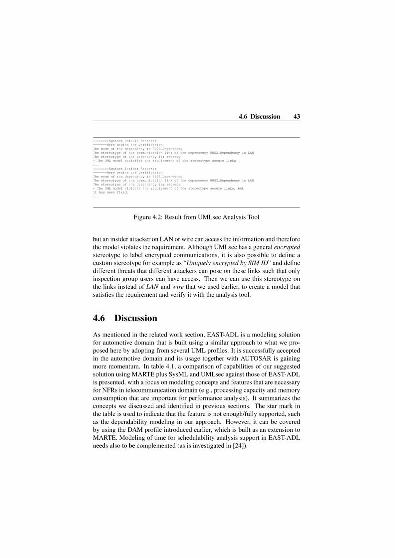
4.6 Discussion 43
::::::::Against Default Attacker=======Here begins the verificationThe name of the dependency is RBS2_DependencyThe stereotype of the communication link of the dependency RBS2_Dependency is LANThe stereotype of the dependency is: secrecy
* The UML model satisfies the requirement of the stereotype secure links....::::::::Against Insider Attacker=======Here begins the verificationThe name of the dependency is RBS2_DependencyThe stereotype of the communication link of the dependency RBS2_Dependency is LANThe stereotype of the dependency is: secrecy
* The UML model violates the requirement of the stereotype secure links, butit has been fixed....
Figure 4.2: Result from UMLsec Analysis Tool
but an insider attacker on LAN or wire can access the information and thereforethe model violates the requirement. Although UMLsec has a general encryptedstereotype to label encrypted communications, it is also possible to define acustom stereotype for example as “Uniquely encrypted by SIM ID” and definedifferent threats that different attackers can pose on these links such that onlyinspection group users can have access. Then we can use this stereotype onthe links instead of LAN and wire that we used earlier, to create a model thatsatisfies the requirement and verify it with the analysis tool.
4.6 Discussion
As mentioned in the related work section, EAST-ADL is a modeling solutionfor automotive domain that is built using a similar approach to what we pro-posed here by adopting from several UML profiles. It is successfully acceptedin the automotive domain and its usage together with AUTOSAR is gainingmore momentum. In table 4.1, a comparison of capabilities of our suggestedsolution using MARTE plus SysML and UMLsec against those of EAST-ADLis presented, with a focus on modeling concepts and features that are necessaryfor NFRs in telecommunication domain (e.g., processing capacity and memoryconsumption that are important for performance analysis). It summarizes theconcepts we discussed and identified in previous sections. The star mark inthe table is used to indicate that the feature is not enough/fully supported, suchas the dependability modeling in our approach. However, it can be coveredby using the DAM profile introduced earlier, which is built as an extension toMARTE. Modeling of time for schedulability analysis support in EAST-ADLneeds also to be complemented (as is investigated in [24]).

44 Paper A
Modeling Feature Our Approach EAST-ADL
Generic NFRs (SysML Style) X XTraceability of NFRs X XTiming, Clock, Schedulability Support X *Memory consumption X 7Processing capacity X 7Power consumption X 7Virtual machines and hierarchical schedulers X 7Hardware platform X XMulticore X 7Allocation and Deployment X XCommunication media X 7Safety 7 XSecurity X 7Variability (product families) 7 XMethodology (e.g., abstraction levels) 7 XDependability (e.g., fault, error... ) * XSynchronization mechanisms X 7Arbitrary Non-Functional Properties X 7Component model X (AUTOSAR)
Table 4.1: Comparison of the suggested UML-based modeling solution withEAST-ADL of Automotive domain.
From the table, it can be seen that by tailoring a UML profile for telecom-munication systems based on the concepts in the three available profiles wediscussed in this paper (MARTE, SysML and UMLsec), it is possible to bettercover the requirements of telecommunication systems, than just re-using onlyEAST-ADL modeling semantics from automotive domain, which are tailoredfor the needs of systems in that domain. Security is one of the specific needs oftelecommunication systems that is not supported by EAST-ADL and has notbeen in the main focus in automotive domain (so far). While on the other hand,safety requirements, which are very important for automotive systems, are ex-plicitly supported in EAST-ADL. For differences between safety and securityrequirements, interested readers can refer to [27].
While in this paper, we discussed a UML-based solution by adopting andtailoring already existing profiles, other methods of defining a specific lan-guage for modeling telecommunication systems are, of course, possible. How-ever, although designing a domain specific language from scratch may matchthe needs of telecommunication systems better, it also implies the need to de-sign dedicated modeling tools, and additional costs for training the users tolearn the new language. On the other hand, some of the benefits of a solutionbased on UML are that many users are already familiar with UML, and thus,
4.7 Conclusion and Future Work 45
the learning curve is smaller. Also, there are already many tools for creatingUML models which can be used ’out of the box’ [7, 8]. One point to remem-ber though is that, as mentioned before, combining different UML profiles canbe problematic in some cases. For example, there is FlowPort both in SysMLand MARTE. However, the semantics of FlowPort in SysML are different fromthose of MARTE. A systematic approach is suggested in [9] to ensure consis-tency in merging UML profiles.
Regarding the management of models, based on the features of the model-ing tool, there can be several scenarios. For example, different models can becreated for different aspects of the system. This can also help with the analysis,as one model for each type of analysis can be created. However, maintainingconsistency between different models of the system and redundant informationmodeling are some of the challenges of this approach. Another scenario couldbe to have one single model for the system, and then have the modeling toolprovide different views of the core model. This way, a user can just focus on theaspects of his/her interest in each view, while modifications are persisted intoone single model representing the system. This method is under developmentin CHESS project [11].
As for the analysis of the models, although this topic is not the main focusof this paper, but we provide some hints here. Basically, the process of anal-ysis can be different for various analysis tools, and depending on which typesof analysis are of interest for different end-users. In case of having just onesingle model of the system, if an analysis tool can ignore non-relevant modelelements and perform analysis on the relevant parts, the model can be fed as in-put to the analysis tool directly. However, if non-relevant model elements maycause problems for the analysis, then it is possible to use model transformationto extract only the relevant ones into a new model appropriate as input for theanalysis tool. Also, if the input model of any analysis tool has its own specificmeta-model, then model transformation techniques can again be used to trans-form the original model into a new model conforming to the meta-model of theanalysis tool.
4.7 Conclusion and Future Work
In this paper, we discussed several challenges in modeling non-functional re-quirements in telecommunication domain. We also suggested a modeling ap-proach for representation of non-functional requirements and their propertiesin this domain. Our approach was to consider telecommunication systems

46 Paper A
as a subdomain of RTES and therefore adopt from available modeling solu-tions for non-functional requirements and their analysis that already exist inRTES domain. Some concepts of MARTE that can cover the requirements oftelecommunication systems were highlighted. For traceability aspects, SysMLand the features it provides in establishing traceability in modeling of non-functional requirements were introduced. Finally, as a specific and intrinsicrequirement in telecommunication domain, it was shown how it is possibleto model and analyze security that is addressed in our suggested approach byadopting UMLsec. This way, we showed not only how it is possible to modeldifferent types of non-functional requirements, but also how model-based anal-ysis can help with the need to perform analysis of non-functional requirementsat earlier phases of development and therefore reduce time and cost. In CHESSEuropean project [11], we are developing a similar solution by using subsetsfrom MARTE, SysML and DAM profile (without security considerations yet)to generate code for telecommunication systems (in this case, Ericsson plat-forms) considering and preserving non-functional requirements modeled usingthe mentioned subsets.
As further studies, it is necessary to augment the suggested approach inthis paper, such as introducing it as part of a well-structured methodology sim-ilar to the methodology suggested in [28]. This methodology is more suitedfor automotive domain as it makes use of EAST-ADL and its abstraction lev-els. Applicability of the same concepts to telecommunication domain could bean interesting topic to investigate. Especially that EAST-ADL offers conceptsfor modeling variability requirements, which can be very useful in telecom-munication domain for modeling product families, targeting cost-sensitivitynon-functional requirements and performing cost analysis.
Also other challenges that exist regarding non-functional requirements ina model-based development approach can be guaranteeing and preservation ofthese requirements on the target platform, introducing runtime adaptability andreconfiguration based on the requirements and handling their violations.
As a last note, in this paper we set the basis for a UML-based solutionfor telecommunication systems similar to EAST-ADL in automotive domain.While it was demonstrated how we can relate high-level and abstract represen-tation of an NFR such as security with its lower level realizations and performsecurity analysis on it, a full scale solution needs contributions from differ-ent industrial partners active in the domain as has been done in the process ofdefining EAST-ADL and AUTOSAR.

Bibliography
[1] Tom Henzinger and Joseph Sifakis. The embedded systems design chal-lenge. In Proceedings of the 14th International Symposium on FormalMethods (FM), Lecture Notes in Computer Science. August 2006.
[2] Andreas Borg, Angela Yong, Par Carlshamre, and Kristian Sandahl. Thebad conscience of requirements engineering : An investigation in real-world treatment of non-functional requirements. In Third Conferenceon Software Engineering Research and Practice in Sweden (SERPS’03),Lund :, 2003.
[3] MARTE specification version 1.0 (formal/2009-11-02). http://www.omgmarte.org, Accessed: August 2011.
[4] EAST-ADL Specification V2.1. http://www.atesst.org, Ac-cessed: August 2011.
[5] OMG SysML Specifcation V1.2. http://www.sysml.org/specs.htm, Accessed: August 2011.
[6] Jan Jurjens. Secure Systems Development with UML, ISBN: 978-3-540-00701-2. Springer, 2005.
[7] Ingo Weisemoller and Andy Schurr. A comparison of standard compliantways to define domain specific languages. pages 47–58, Berlin, Heidel-berg, 2008. Springer-Verlag.
[8] Bran Selic. A systematic approach to domain-specific language designusing uml. In Proceedings of the 10th IEEE International Symposiumon Object and Component-Oriented Real-Time Distributed Computing,2007.
47

48 Bibliography
[9] Florian Noyrit, Sebastien Gerard, Francois Terrier, and Bran Selic. Con-sistent modeling using multiple uml profiles. In Model Driven Engineer-ing Languages and Systems. 2010.
[10] Andreas Borg, Mikael Patel, and Kristian Sandahl. Good practice and im-provement model of handling capacity requirements of large telecommu-nication systems. In RE ’06: Proceedings of the 14th IEEE InternationalRequirements Engineering Conference, Washington, DC, USA, 2006.
[11] CHESS Project: Composition with Guarantees for High-integrity Embed-ded Software Components Assembly. http://chess-project.ning.com/, Accessed: August 2011.
[12] Telecommunication Standardization Sector (ITU-T). http://www.itu.int/en/pages/default.aspx, Accessed: June 2011.
[13] Muhammad R. Abid, Daniel Amyot, Stephane S. Some, and GunterMussbacher. A uml profile for goal-oriented modeling. In Procs. ofSDL’09, 2009.
[14] Torsten Lodderstedt, David A. Basin, and Jurgen Doser. Secureuml: Auml-based modeling language for model-driven security. In Proceedingsof the 5th International Conference on The Unified Modeling Language,UML ’02, 2002.
[15] Khaled Alghathbar and Duminda Wijesekera. authuml: a three-phasedframework to analyze access control specifications in use cases. In FMSE’03: Proceedings of the 2003 ACM workshop on Formal methods in se-curity engineering, pages 77–86, New York, NY, USA, 2003. ACM.
[16] A. Cenys, A. Normantas, and L. Radvilavicius. Designing role-basedaccess control policies with uml. In Journal of Engineering Science andTechnology Review, volume 2, pages 48–50, 2009.
[17] Karine P. Peralta, Alex M. Orozco, Avelino F. Zorzo, and Flavio M.Oliveira. Specifying security aspects in uml models, September 2008.
[18] S. Demurjian, J. Pavlich-Mariscal, and L. Michel. Enhancing uml tomodel custom security aspects. In Proceedings of the 11th InternationalWorkshop. on Aspect-Oriented Modeling, October 2007.

[19] Thuong Doan and Steven Demurjian. A.: Mac and uml for secure soft-ware design. In In: Proc. of 2nd ACM Wksp. on Formal Methods inSecurity Engineering, pages 75–85. ACM Press, 2004.
[20] Siv Hilde Houmb and Kine Kvernstad Hansen. Towards a uml profile forsecurity assessment. In Workshop on Critical Systems Development withUML, 2003.
[21] AADL. The Architecture Analysis & Design Language: An Introduction. http://www.aadl.info/aadl/currentsite/aadlstd.html, Accessed: August 2011.
[22] AUTOSAR Home Page. http://www.autosar.org/, Accessed:August 2011.
[23] Saoussen Ansi, Arnaud Albinet, Sara Tucci-Pergiovanni, ChokriMraidha, Sebastien Gerard, and Francois Terrier. Completing east-adl2 with marte for enabling scheduling analysis for automotive applica-tions. In Embedded Real Time Software and Systems Conference (ERTS),Toulouse, France, 2010.
[24] TIMMO Project. http://www.timmo.org/, Accessed: August2011.
[25] Michel dos Santos Soares and Jos L. M. Vrancken. Model-driven userrequirements specification using sysml. Journal of Software, 3:57–68,2008.
[26] S. Bernardi, J. Merseguer, and D. Petriu. A dependability profile withinmarte. Journal of Software and Systems Modeling, 2009.
[27] Eirik Albrechtsen. Security vs safety. NTNU - Norwegian Universityof Science and Technology http://www.iot.ntnu.no/users/albrecht/, Accessed: May 2011.
[28] A. Albinet, J-L. Boulanger, H. Dubois, M-A. Peraldi-Frati, Y. Sorel, andQ-D. Van. Model-based methodology for requirements traceability inembedded systems. In Procs. of ECMDA’07, Haifa, Israel, June 2007.


Chapter 5
Paper B:Modeling and Trade-offAnalysis of NFRs
Mehrdad Saadatmand, Antonio Cicchetti and Mikael SjodinMRTC report ISSN 1404-3041 ISRN MDH- MRTC-267/2012-1-SE,Malardalen Real-Time Research Centre, Malardalen University, April, 2012.
51

Abstract
In this paper we introduce a generic approach to analyze system design modelswith regard to the satisfaction of their Non-Functional Requirements (NFRs)to enable the evaluation of their NFRs’ trade-offs. NFRs and their satisfactionbecome especially critical and deserve more attention in certain application do-mains such as real-time and embedded systems. This is mainly due to the con-straints and resource limitations in these systems. A design that cannot achievethe functionality of the system under these limitations can mean a failure. How-ever, one big issue is that NFRs are interconnected and cannot be considered inisolation as they can have direct impacts on each other like security and perfor-mance. This means that a careful balance and trade-off analysis among NFRsis necessary. In doing so, the role of functional parts that contribute and areimplemented to satisfy an NFR should also be taken into account. We focus onthese needs and identify what information about NFRs is required in order toperform trade-off analysis and comparison of design models. We propose andexplain our approach to incorporate this information into system models usingUML profiling method to annotate model elements with necessary informa-tion and then calculate satisfaction values of NFRs using model transformationtechnique.

5.1 Introduction 53
5.1 Introduction
The role of Non-Functional Requirements (NFR) throughout the software de-velopment process is gaining more and more attention, especially that the im-proper handling of NFRs has been identified as an important source of failurein many projects [1, 2]. However, NFRs are still rarely taken into accountseriously and treated as first-class elements in software development, and aremostly considered as an after-thought in the final phases of development [3, 4].There are several reasons that contribute to this fact. For example, NFRs areusually stated in an informal way and at a high abstraction level, therefore, ap-propriate methods and tools are required that can incorporate them at earlierphases of development and along with functional requirements. The impor-tance of the integration of NFRs with functional parts becomes more apparentwhen we realize that different NFRs on the same functionality can result indifferent design decisions and implementations [5].
Proper handling of NFRs is even critical in certain domains such as em-bedded and real-time systems. Successful design of these systems dependsheavily on the satisfaction of their non-functional requirements. This is mainlydue to the constraints and limitations of these systems in terms of available re-sources [6]. Therefore, an embedded system needs to achieve its functionalityunder these limitations and NFRs. The problem is that each design decisioncan have impact on the system’s NFRs and the system designer should be ableto identify and evaluate these impacts. For example, if there is an executiontime constraint on a component responsible for sorting numbers, then choos-ing a slower algorithm than a more time-optimized one can lead to the viola-tion of system requirements and deviation of its behavior from the desired one.This situation becomes more complicated when we realize that NFRs not onlycrosscut different parts of a system, but can also have mutual impacts on eachother. For example, choosing a time-optimized and faster sorting algorithmcan help with the satisfaction of the timing requirements but may require morememory and thus violate memory constraints. Also, an NFR such as securitycrosscuts different parts of a system (e.g., user interface, database, communi-cations and network transmissions) and affects some other NFRs like perfor-mance [7]. Therefore, the tools and methods that are suggested for handling ofNFRs should not only be able cover and cope with their informal nature, highabstraction level, and integration with functional ones, but also should be ableto help with identifying their dependencies and impacts on each other to enableanalysis of their trade-off.
Model-Based Development (MBD) helps to raise the abstraction level and

54 Paper B
cope with the design complexity of systems. This can make it especially in-teresting for the design of real-time embedded systems which can have highdegree of complexity. By raising the abstraction level, MBD also enables anal-ysis at earlier phases of development which in turn enables identification ofproblems before reaching the implementation phase [8]. Since NFRs have ahigh abstraction level [3] and also MBD provides views of the system at higherabstraction levels, providing an MBD approach to incorporate NFRs into mod-els is deemed more appropriate especially in integrating NFRs with functionalaspects of the system.
In this paper, we propose a UML profile [9] for trade-off analysis of genericNFRs. The analysis in this work implies analyzing the dependencies and im-pacts of NFRs (irrespective of their type, e.g., performance, security. . . ) aswell as the functional features of the system to provide system designers with abetter insight into how good a system design is in terms of the satisfaction levelof its NFRs. The main contributions can thus be summarized in the followingpoints:
• providing an approach to capture and model NFRs in an open andgeneric way and include them with functional features as well as thedependencies and relationships among them,
• enabling designers to evaluate and compare different design models withregard to their NFRs and identify designs which can result in better over-all satisfaction of NFRs,
• identifying deviations in the satisfaction of system’s NFRs and highlight-ing potentially problematic parts that deserve more attention.
Enabling trade-off analysis of NFRs through a UML profile has severalkey benefits. UML is a standard modeling solution already adopted by in-dustry and there are many design and analysis tools based on it. By offeringa UML-based solution for trade-off analysis of NFRs, it becomes possible tomake use of currently available tools. Also, the learning curve for developersalready using UML will be less which implies both cost and time savings forcompanies [9]. Moreover, the approach we propose here tries to extend designmodels with necessary information to enable trade-off analysis of NFRs, andthus can enable using already designed system models and can save modelingefforts. We propose stereotypes in our profile by which model elements can bedecorated and related with the necessary information that enable designers toconsult models for specific information about NFRs and trade-off analysis ofthem.

5.2 Non-Functional Requirements 55
The remainder of the paper is structured as follows. In Section 5.2, wehave a look at NFRs in general, including their definition, characteristics, andthe issues around them. In Section 5.3, we discuss the required characteristicsand information that a solution for managing trade-offs of NFRs should beable to offer. Section 5.4 explains the profile structure and concepts. Section5.5 shows an application of the profile in a portion of a mobile phone designand the analysis is then performed on the annotated model. In Section 5.6, wewill have a look at other related works and finally in Section 5.7, conclusionsare made and future directions are explained.
5.2 Non-Functional RequirementsRequirements are generally divided into two main categories: functional andnon-functional. In the simplest form, functional requirements are those whichdefine what the system should do, while the term non-functional requirementis used for requirements which specify how a system should perform or assuggested in [10] ”a non-functional requirement is an attribute of or a con-straint on a system”. There is a big number of suggested definitions for non-functional requirements which are discussed in [11]. These requirements areusually described with terms that end with ’ility’ such as availability, ’ity’ suchas atomicity, while a few other ones such as performance and user-friendlinessdo not follow this pattern. According to the IEEE standards, 610.12-1990 andISO/IEC/IEEE 24765:2010(E) [12, 13], the following definitions is providedfor non-functional requirements: ”a software requirement that describes notwhat the software will do but how the software will do it (i.e., design con-straints)”.
One concept that is often confused with NFR is the concept of Non-Functional/Extra-Functional Property (NFP/EFP). The former can be consid-ered as an expression of a need (possibly informal), and the latter as a statementthat is usually asserted formally and can be therefore proven and analyzed (e.g.,calculated response time of a component). This implies that ”a requirement canrequire that a certain property holds (e.g., absence of deadlock, meeting dead-line, not overflowing a queue, etc.) and that in order for a property to holda number of requirements may have to be met, which we normally neitherexpress nor assert formally” 1. For example, ”response time of a componentshould not exceed 2ms” is a requirement, while ”response time of component
1These definitions have been provided and formulated with the help of Prof. Tullio Vardanega,University of Padova, Italy

56 Paper B
A never exceeds 2ms” and ”response time of component B is equal to 1ms”are expressions of properties in a system. In [14], NFP is used instead of NFRwhen talking about the final product implying that the requirement has beenconcretized and become an actual property of it.
NFRs have several characteristics that make their consideration in softwaredevelopment process a challenging task. While Functional Requirements (FRs)are typically realized and implemented one by one and step by step as part ofthe software product, NFRs do not usually follow this pattern and the designdecisions taken to implement the functionality of the software affect their sat-isfaction. Similarly, while FRs normally have localized effects, NFRs are basi-cally specifications of global constraints (e.g., performance, security, availabil-ity, etc.) to be satisfied by the software [3]. In this regard, NFRs can crosscutdifferent parts of the system (e.g., security). Also, NFRs are interconnected andthere are dependencies among them which implies that the satisfaction of oneNFR can conflict and impair the satisfaction of other ones. Therefore, trade-off analysis is required to identify such impacts and establish balance amongNFRs in a system.
On the other hand, NFRs are usually specified in an abstract and informalway [3, 14] and thus, providing a more formal approach using model-baseddevelopment which tries to raise the abstraction level of systems can help withthe treatment of NFRs during the software development. There are several rea-sons for incorporating NFRs in the development process and explicitly dealingwith them. Among them are the increasing number of applications such asin real-time embedded systems where NFRs play a critical role, and also thestrong interaction between functional and non-functional requirements. More-over, an explicit treatment of NFRs facilitates prediction of quality propertiesof the final product in a more reliable and reasonable way [14].
The approaches that are suggested for the explicit treatment of NFRs aresometimes categorized into two groups: product-oriented and process-oriented[15]. The former approaches try to formalize NFRs in the final product inorder to perform evaluation on the degree to which requirements are met. Inthe latter approaches, NFRs are considered along with functional requirementsto justify design decisions and guide and rationalize the development processand construction of the software in terms of its NFRs [15, 14].

5.3 Characteristics of the Solutions 57
5.3 Characteristics of the Solutions
Based on the identified challenges that were discussed previously, in this sec-tion we formulate the key characteristics that a model-based solution for rep-resentation and trade-off analysis of NFRs should have.
Traceability of design decisions related to an NFR: considering that NFRsusually crosscut different parts of the system, the designer should be able to un-derstand which parts of the system contribute (both positively and negatively)to a specific NFR; for example, an encryption component that is intended tosatisfy security requirements. With this information, after trade-off analysis,the designer can identify parts of the systems that should be removed, replaced,improved or kept.
Traceability among NFRs: throughout the whole design process of a sys-tem, higher level NFRs are refined and broken down into more concrete ones,particularly in a top-to-bottom approach. For example, a high level and abstractNFR such as security can be refined into access control or encryption require-ments at lower levels. Therefore, in order to check the satisfaction of securityin the system, it is necessary to keep track of its refinements and lower levelrequirements that cover different aspects of security along with information onhow much each one contributes towards its parent NFR.
Satisfaction level of an NFR: it should be possible to evaluate the totalsatisfaction level/degree of an NFR in the system. This is necessary to comparecurrent design against system specification and customer requirements as wellas different design alternatives. In the end, the goal is that the designer gets anidea to what extent each NFR is satisfied. Judging where this level is acceptableor not is done as the next step after applying the approach we suggest in thispaper and probably by checking it with the stakeholders.
Impact of an NFR on other NFRs: as mentioned before, NFRs cannot beconsidered in isolation in a system without taking into account their impactson each other. Therefore, it is required to identify and evaluate the effects thata model element and design decision that is used to satisfy one NFR, has onanother NFR in the system. For example, performing heavy computations byan encryption component in an embedded system can also mean consumingmore battery. Therefore, the side effects of such design decision should beidentifiable for the designer.
Priority of an NFR: not all NFRs have the same importance in the system.In order to increase the overall satisfaction of NFRs and also to resolve con-flicts among NFRs (reduce the impact of one NFR in favor of another), it isnecessary to know the importance of each NFR and compare them. Consid-

58 Paper B
ering priority for NFRs is also important in order to capture the preferencesof customers/users. Similarly, priorities can also be considered for differentfeatures implemented to satisfy an NFR.
Coherent terms for NFRs: one subtle problem with NFRs that is more oftennoticed in large enterprises is that different (sub)departments may have differ-ent interpretations for an NFR term or use different terms to refer to an NFR[16]. Therefore, it is important to provide a coherent and consistent notationfor defining NFRs and relating them to design elements.
Coherent measurements of NFRs: to compare different NFRs and performtrade-off analysis among them, evaluation of the satisfaction degree and im-pacts of NFRs should follow a coherent representation. In other words, thecriteria or metrics used should be such that to allow pair-wise comparison ofNFRs (e.g. using the same types, scales and units, or a convertible format).
5.4 Suggested Profile
Figure 5.1 shows the structure of our profile to include the necessary informa-tion mentioned in the previous section in models to enable trade-off analysis ofNFRs.
satisfactionValue: Double{readOnly}rationale: Stringpriority: IntegerdeviationIndicator: Double{readOnly}
«stereotype»NFR
«metaclass»UML::Classes::Kernel::Classifier
NFR Profile
«metaclass»UML::Classes::Dependencies::Realization
contributionValue: Double
«stereotype»NFRContributes «stereotype»
NFRApplies
parentNFR
0..1
childNFR
0..*
«stereotype»System
satisfactionValue:Double{readOnly}
satisfactionValuel: Double{readOnly}rationale: Stringpriority: IntegerdeviationIndicator: Double{readOnly}
«stereotype»Feature
0..*
1..*
childFeature
0..*
parentFeature
0..*
0..1
«metaclass»UML::Classes::Dependencies::Dependency
«stereotype»NFRCooperates
«stereotype»NFRImpacts
impactValue: Double
Figure 5.1: Profile for Trade-off analysis of NFRs
System: this stereotype is used to annotate the system which is the con-text of the analysis and to which different NFRs belong. It includes satisfac-

5.4 Suggested Profile 59
tionValue tagged value to represent quantitatively the total satisfactions of thesystem’s NFRs.
NFR: each NFR is identified using this stereotype. A higher level NFR(in terms of abstraction level) can be refined into one or more other NFRs.Therefore, there is an association relationship to itself (reflexive aggregation).
Feature: this stereotype represents a feature in the system that con-tributes to the satisfaction of an NFR and is an equivalent of Operationaliza-tion concept in NFR framework and Softgoal Interdependency Graph (SIG)[17] (described later in the paper) or tactics as used in [4].
NFRContributes: this stereotype which is used on relationships be-tween model elements shows that an element (NFR or Feature) contributesdirectly to the satisfaction of another element. The contributionValue propertyof this stereotype is used to specify the degree of this contribution.
NFRImpacts: this is similar to NFRContributes stereotype but is used toinclude the impact of a model element on other NFRs in the system in a quan-titative manner. In other words, this stereotype is defined to capture the sideeffects of features and NFRs. ImpactValue property of this stereotype showsthe degree of the impact. A positive value for the ImpactValue implies a posi-tive side effect, and a negative one implies a negative side effect accordingly.
NFRCooperates: is used to relate two or more elements that cooper-ate together to satisfy an NFR. This is similar to the AND relation in NFRframework and SIG.
NFRApplies: the relation between NFR related model elements andfunctional ones can be modeled using NFRApplies stereotype (e.g. an NFRthat applies to a component).
Rationale: this property and tagged value in NFR and Feature stereo-types can be used to include the description and rationale for an NFR, its re-finements into other NFRs or Features implementing it.
Priority: this property in NFR and Feature stereotypes is used to cap-ture customer preferences and priorities in terms of the importance of NFRsand Features. This helps to identify less important parts in case modificationand removal of some features or NFRs is necessary.
DeviationIndicator: is a read-only property which is calculatedand set automatically. DeviationIndicator takes into account the priority andsatisfaction value, and provides a number which indicates to the designer theimportance and magnitude of how much the satisfaction of an NFR or Fea-ture has deviated/violated. While the satisfaction value does not reflect userpreferences and priorities, the deviation indicator value shows which parts ofthe system deviated more from the specification (i.e., being fully satisfied) and

60 Paper B
need to be modified to achieve a better satisfaction level.There are also several rules on the elements and their relationships de-
scribed above:
• The allowed range of values to set is between -1 and 1 (except for pri-ority). For example a negative value on the NFRImpacts relationshipshows the negative impact of the source element on the target element.
• The satisfaction value for each leaf node is considered to be 1.
• Allowed values for priority are: 1 (very low), 2 (low), 3 (medium), 4(high), 5 (very high).
• The sum of contribution values of the links connecting children nodes(refinement/lower level elements) to their parent should be less or equalto 1 (maximum is 1).
• Contribution of a child node to its parent is calculated as the satisfac-tionValue of the child node multiplied by its contributionValue or im-pactValue.
• The satisfactionValue of a node is, therefore, calculated as the sum of thecontributions from all of its children nodes plus the sum of the impacts ofall other nodes, divided by the total number of NFRImpacts relationshipsto it plus 1. In other words, if sk is the satisfaction value for each childnode of a node, lk is the value on the link that connects the child node k toits parent node (NFRContributes), and ij is the impact value of anothernode on this parent node, the satisfaction value of the parent node iscalculated as:
∑sk ∗ lk +
∑nij
n+ 1(5.1)
This calculation is performed starting from leaf nodes (considering thatthe satisfaction of leaf nodes is 1) and is calculated recursively upwardstoward the top element which is the system.
• The DeviationIndicator is calculated after the calculation of satisfactionvalue using the following formula:
DeviationIndicator =
Priority − Priority ∗ SatsifactionV alue(5.2)

5.5 Implementation and Usage Example 61
Based on this calculation and considering that the SatisfactionValue isalways between -1 and 1 and priority is an integer value between 1 and5, the value of DeviationIndicator will be in the range of [0, 10]. Theperfect situation is when the DeviationIndicator value is 0, and the morethis value increases the more is the deviation from the desired design,and thus, it indicates a bigger and more severe problem.
5.5 Implementation and Usage Example
The profile concepts described in the previous section were implemented inMDT Papyrus [18]. In Figure 5.2 an example usage of the profile is shown onparts of a mobile phone system. Two NFRs are defined. One on the quality ofthe taken camera picture and the other one on the battery life. There are twofeatures that contribute to the quality of taken photos: usage of a flash and typeof the lens. Also two features are considered for Battery Life: adjustmentof screen’s brightness level and auto standby feature. The contribution of eachfeature to its parent NFR is annotated using NFRContributes stereotype andits contributionValue attribute. In this system, the use of flash consumes lotsof battery. The impact of the Flash feature on Battery Life is thereforespecified using NFRImpacts stereotype and its impactValue attribute which is-0.8. Preferences of the customer in terms of the relative importance of NFRsand Features are captured through the priority property of each model element.For example, Battery Life has priority level 5 which means it is moreimportant than the Camera Picture Quality which has priority level 4.Satisfaction and DeviationIndicator values are initially 0 as no calculation hasyet been done on the model.
One point here is that, although these values are assigned subjectively bythe system designer, there are methods such as sensitivity analysis [4] that helpto increase the confidence in the chosen decision. Now what we need to under-stand is the impact that having the Flash feature has on the system.
By having the necessary information in the model, it is now possible to per-form analysis on the model to determine impacts of each design decision on thesystem and evaluate their dependencies. To traverse the model and perform cal-culations, we have developed a model-to-model (M2M) transformation usingQVT Operational language (QVT-O)[19] in Eclipse [20]. It reads as input aUML model annotated with our profile, traverses the nodes and calculates sat-isfaction values and writes the results back in the same model. In other words,we use an in-place transformation (i.e. input and output models are the same).

62 Paper B
Figure 5.2: Example usage of NFR profile for a Mobile Phone (before calcula-tions)
To calculate the satisfaction values, a recursive algorithm is used in themodel transformation based on the rules mentioned in the previous section. Foreach node, all the incoming links that have NFRImpacts or NFRContributesstereotypes are retrieved. If a node does not have any such links (meaning thatit is a leaf node), its satisfaction value is set to 1. Otherwise, the source ofthe link, which is another node, is retrieved and the algorithm continues bycalculating the satisfaction value of the source node; hence the recursion.
The algorithm basically applies Formula 5.1 which is mentioned in the pre-vious section. For example, in Figure 5.2, the satisfaction values for AutoStandby and Brightness Level features are set to 1, since they are leafnodes. The satisfaction value of Battery Life is then calculated as thesatisfaction value of Brightness Level (1) multiplied by the value onthe link that connects it to Battery Life (0.5), plus the same multiplica-tions for Auto Standby (1*0.5) and Flash (1*-0.8) which results in 0.20.The discrepancy observed between this calculated value (0.20) and the one inFigure 5.3 (0.199. . . ) which is calculated automatically through the in-placemodel transformation on the model is due to the OCL implementation of real

5.5 Implementation and Usage Example 63
numbers that QVT-O uses.
Figure 5.3: Analyzed model of the system
By performing the transformation on the whole model, the satisfaction val-ues are calculated for each node and propagated upwards toward the systemelement as shown in Figure 5.3:
(1 ∗ 0.4 + 1 ∗ 0.6) ∗ 0.3 + ((1 ∗ 0.5 + 1 ∗ 0.5)− 0.8) ∗ 0.7 = 0.44
Therefore, the total satisfaction value in this case will be 0.44. Trying theprocedure again on the same model but without having the Flash featureresults in:
(1 ∗ 0.6) ∗ 0.3 + (1 ∗ 0.5 + 1 ∗ 0.5) ∗ 0.7 = 0.88
Similarly, as soon as the satisfaction value for a feature or NFR is calcu-lated, the deviationIndicator property value is also calculated using Formula 5.2and set in the model. For the leaf nodes, since their satisfaction values are al-ways 1, their deviationIndicator value will always result in 0. For the CameraPicture Quality NFR, the deviationIndicator value is calculated as:

64 Paper B
4− 4 ∗ 1.0 = 0
which means that there has been no deviation from the desired design.However, for the Battery Life NFR, this value will be:
5− 5 ∗ 0.2 = 5− 1 = 4
This value shows that there exists some deviation which in this case is dueto the side effects of having the Flash feature on Battery Life. Basedon the specification of the actual system that is being developed, this could, forinstance, imply that the type of flash is not good enough in terms of energyconsumption for this system and needs re-consideration.
Since the calculation of the deviation indicator is based on the priority ofeach NFR or Feature, in a larger model where deviations in several parts ofthe system are observed, the user can understand on which parts of the model,modifications should be done and in which order. In other words, parts withhigher deviation value indicate more critical problems and deserve more atten-tion.
Figure 5.4: Analyzed model of the system without the Flash feature

5.6 Related Work 65
Figure 5.4 shows performing the analysis on the same model but withoutthe Flash feature. This model could, for example, represent another family ofmobile phones or another usage scenario. It can be seen that the total satisfac-tion level of the system is higher in this case: 0.88 versus 0.44 in the previouscase. The removal of the Flash feature, however, also causes some deviation(1.6) for the Camera Picture Quality NFR.
Based on these calculations, our suggested approach enables a more accu-rate comparison of design alternatives considering the interdependencies andtrade-offs among different NFRs of the systems helping designers to make bet-ter decisions. Also the introduced modeling concepts and calculations aboveprovide for several interesting features. One feature is the possibility to opti-mize the total satisfaction of the system considering different design alterna-tives. For example, in the mobile phone system described, if the designer needsto select among several possible solutions that contribute to better image qual-ity, he/she can find the ones that lead to the highest satisfaction value of thesystem. Another possibility is to have run-time adaptability or re-configurationbased on different quality of service levels. For example, if the battery levelgoes low beyond a certain limit, the system can go into a power-saving modeusing features that incur minimum impact on battery consumption or replacingactive components with back-up/standby ones which may provide lower quali-ty/fewer services but consume less battery (e.g., in design diversity techniques[21]). Without the analysis introduced here, such a decision may not only behard, but also will be blind in the sense that the side effects of a feature/com-ponent replacement on other aspects of the system will be unknown.
5.6 Related Work
There are versatile research works that try to target different issues regardingNFRs. [22] focuses on the problem of informal and separated documentationof design decisions and NFRs. To alleviate the problem, it introduces two pro-files to model design decisions and generic NFRs to treat them as first-classentities in software architectures and maintain the traceability of design deci-sions and architectural elements. NFR framework proposed in [17] is one ofthe fundamental works in the area of NFRs which is a process-oriented andgoal-oriented approach. It uses Softgoal Interdependancy Graph (SIG) to rep-resent NFRs, their refinements and entities that NFRs are applied to (termedas Operationalization), and the interdependencies among them to include theirimpacts and relations. The dependencies and contributions of NFRs are spec-

66 Paper B
ified using make, hurt, help, break and undetermined relationship types. Be-sides NFR softgoals, and operationalizating softgoals, NFR framework alsointroduces claim softgoals which convey the rationale and argument for oragainst a design decision. It provides notations to mark critical NFRs in thegraph and also an evaluation procedure to determine satisfaction and conflictsof NFRs. The approach suggested in NFR framework is basically a quali-tative approach. Moreover, the criticality concept in NFR framework seemsmore suitable for developers and does not convey enough information for pri-oritization of NFRs particularly from the customer’s perspective and also forperforming trade-off analysis[4]. [23] offers a UML profile for modeling SIGand concepts of NFR framework to represent NFRs as UML elements in or-der to integrate them with functional parts of the system (that are modeled inUML). T. Marew et al. [4] introduces Q-SIG which is a quantified versionof SIG that enables quantitative evaluation of impacts and trades-offs amongNFRs. In this paper, we introduced modeling concepts that enable designers toapply the Q-SIG approach in the form of UML models, and provided a toolingsolution for evaluation and trade-off analysis of NFRs on these models usingthis approach. ProcessNFL that is introduced in [3] is a textual language fordescribing non-functional properties during the software development. It of-fers templates for describing three abstractions that capture different aspectsof non-functional properties: NF-Attributes, NF-Properties and NF-Actions.Moreover, the language enables to express the relationships between these ab-stractions to include dependencies and impacts of non-functional properties inthe system. The language is an effort for explicit treatment of non-functionalproperties during software development.
While deciding on the satisfaction of NFRs is mainly considered to be sub-jective, there are several works that try to provide quantifications for NFRs toease their evaluation and analysis. Kassab et al. in [1, 24] offer a method toquantify NFR size in a software project based on the functional size measure-ment method to help with the estimation of effects of NFRs on the effort ofbuilding the software in a quantitative manner. [2] makes use of RequirementsHierarchy Approach (RHA) as a quantifable method to measure and manipu-late the effects that NFRs have on a system. It does so by capturing the effectsof functional requirements. In [25], an approach for quantifying NFRs basedon the characteristics of and information from execution domain, applicationdomain and component architectures is suggested.
SysML [26] which is a UML profile for system engineering also includesa package for generic modeling of requirements (both NFRs and FRs) and therelationships among them. These relationships mainly capture the traceabil-

5.7 Conclusion and Future work 67
ity and hierarchy of requirements (e.g., refinement). While SysML does notspecifically focus on NFRs and analysis of them, our approach and SysML canbe used together to complement each other.
5.7 Conclusion and Future work
In this paper, a UML profile for modeling NFRs and their dependencies wasintroduced to enable performing trade-off analysis among them. It was shownhow it can help to compare different design models, determine which onesachieve a higher satisfaction of the NFRs, and identify parts of the model whichmight be good candidates for modification to reach a higher satisfaction levelin the system.
One point to note about the proposed approach is the issue of scalabilityand evaluating how it can be applicable for very complex and large systems.While this is basically a general concern in model-driven engineering, there aresome solutions for management of large models which can be considered suchas using a multi-view approach and providing better degree of separation ofconcerns by defining different views over the model of a system [27]. Also inthis work, we assumed that the designer can provide values (though subjective)for contribution and impact relationships among NFRs and functional features.As mentioned, there are some techniques that help system designers in pro-viding such quantitative information. However, this may also imply that oursuggested approach can be especially more applicable for component-basedsystems where systems are built out of already existing components and thusmore knowledge about their characteristics and behaviors are available (e.g.,memory usage, execution time). Moreover, our approach can also be usefulin the analysis of software architecture evolution, when new requirements orfeatures are introduced into a system or existing ones are modified [28].
As the continuation of this work, we plan to develop an analysis tool as anEclipse plug-in that can read as input, models annotated with our NFR trade-off profile and provide total satisfaction values for different NFRs, identifyparts contributing negatively to an NFR, and perform calculations for overalloptimization of NFRs in the system considering different design alternativesand scenarios. With the help of the tool, when some parts of the system need tobe changed and updated, the user can identify the side effects of such changeson other parts and the system as a whole in terms of NFRs, at model level andbefore implementing the intended changes. The defined profile depicted in thispaper is the first step toward enabling such features.

68 Paper B
Using the introduced modeling concepts here along with a back-annotationmechanism in model-based development of embedded systems will also be aninteresting topic to further investigate and work on. Having such a mechanism,it would be possible to monitor the system and provide feedbacks to the designmodel about possible violations in the system (or any of its subsystems) interms of satisfaction levels of their NFRs. Also, the usage of the suggestedapproach for run-time adaptability and re-configuration of systems is anotherdirection for further investigation.
5.8 AcknowledgementsThis work has been partially supported by the CHESS European Project(ARTEMIS-JU100022) [29] and Xdin AB [30].

Bibliography
[1] Mohamad Kassab, Olga Ormandjieva, Maya Daneva, and Alain Abran.Software process and product measurement. chapter Non-FunctionalRequirements Size Measurement Method (NFSM) with COSMIC-FFP,pages 168–182. Springer-Verlag, Berlin, Heidelberg, 2008.
[2] Andrew J. Ryan. An approach to quantitative non-functional require-ments in software development. In Proceedings of the 34th Annual Gov-ernment Electronics and Information Association Conference, 2000.
[3] N.S. Rosa, P.R.F. Cunha, and G.R.R. Justo. Processnfl: a language fordescribing non-functional properties. In System Sciences, 2002. HICSS.Proceedings of the 35th Annual Hawaii International Conference on,pages 3676 – 3685, jan. 2002.
[4] Tegegne Marew, Joon-Sang Lee, and Doo-Hwan Bae. Tactics basedapproach for integrating non-functional requirements in object-orientedanalysis and design. The Journal of Systems and Software, 82:1642–1656, October 2009.
[5] Yi Liu, Zhiyi Ma, and Weizhong Shao. Integrating non-functional re-quirement modeling into model driven development method. In SoftwareEngineering Conference (APSEC), 2010 17th Asia Pacific, pages 98 –107, December 2010.
[6] Thomas Henzinger and Joseph Sifakis. The embedded systems designchallenge. In Jayadev Misra, Tobias Nipkow, and Emil Sekerinski, edi-tors, FM 2006: Formal Methods, volume 4085 of Lecture Notes in Com-puter Science, pages 1–15. Springer Berlin / Heidelberg.
69

70 Bibliography
[7] Jongdeog Lee, Krasimira Kapitanova, and Sang H. Son. The price ofsecurity in wireless sensor networks. Journal of Computer and Telecom-munications Networking, 54:2967–2978, December 2010.
[8] Bran Selic. The pragmatics of model-driven development. IEEE SoftwareJournal, 20:19–25, September 2003.
[9] Bran Selic. A systematic approach to domain-specific language designusing uml. In Object and Component-Oriented Real-Time DistributedComputing, 2007. ISORC ’07. 10th IEEE International Symposium on,pages 2 –9, May 2007.
[10] Martin Glinz. On non-functional requirements. In 15th IEEE Interna-tional Requirements Engineering Conference, pages 21–26, New Delhi,India, October 2007.
[11] Lawrence Chung and Julio Cesar Prado Leite. Conceptual modeling:Foundations and applications. chapter On Non-Functional Requirementsin Software Engineering, pages 363–379. Springer-Verlag, Berlin, Hei-delberg, 2009.
[12] IEEE Standard Glossary of Software Engineering Terminology. IEEE Std610.12-1990, 1990.
[13] Systems and software engineering – Vocabulary (IEEE Standard).ISO/IEC/IEEE 24765:2010(E), 15 2010.
[14] Nelson S. Rosa, George R. R. Justo, and Paulo R. F. Cunha. A frameworkfor building non-functional software architectures. In Proceedings of the2001 ACM symposium on Applied computing, SAC ’01, pages 141–147,New York, NY, USA, 2001. ACM.
[15] J. Mylopoulos, L. Chung, and B. Nixon. Representing and using nonfunc-tional requirements: a process-oriented approach. Software Engineering,IEEE Transactions on, 18(6):483 –497, jun 1992.
[16] Mehrdad Saadatmand, Antonio Cicchetti, and Mikael Sjodin. Uml-basedmodeling of non-functional requirements in telecommunication systems.In The Sixth International Conference on Software Engineering Advances(ICSEA 2011), October 2011.

Bibliography 71
[17] Lawrence Chung, Brian A. Nixon, Eric Yu, and John Mylopoulos. Non-Functional Requirements in Software Engineering, volume 5 of Interna-tional Series in Software Engineering. Springer, October 1999.
[18] MDT Papyrus . http://www.eclipse.org/modeling/mdt/papyrus/, Accessed: February 2012.
[19] QVT Operational Language. http://www.eclipse.org/m2m/,Accessed: February 2012.
[20] Eclipse Modeling Framework Project (EMF). http://www.eclipse.org/modeling/emf/, Accessed: February 2012.
[21] John P. J. Kelly, Thomas I. McVittie, and Wayne I. Yamamoto. Imple-menting design diversity to achieve fault tolerance. IEEE Software Jour-nal, 8:61–71, July 1991.
[22] Liming Zhu and Ian Gorton. Uml profiles for design decisions and non-functional requirements. In Proceedings of the Second Workshop onSHAring and Reusing architectural Knowledge Architecture, Rationale,and Design Intent, SHARK-ADI ’07, pages 8–, Washington, DC, USA,2007. IEEE Computer Society.
[23] Sam Supakkul. A uml profile for goal-oriented and use casedriven rep-resentation of nfrs and frs. In In Proceedings of the 3rd InternationalConference on Software Engineering Research, Management and Appli-cations, pages 112–121, 2005.
[24] M. Kassab, M. Daneva, and O. Ormandjieva. Early quantitative assess-ment of non-functional requirements, June 2007.
[25] Raquel Hill, Jun Wang, and Klara Nahrstedt. Quantifying non-functionalrequirements: A process oriented approach. In Proceedings of theRequirements Engineering Conference, 12th IEEE International, pages352–353, Washington, DC, USA, 2004. IEEE Computer Society.
[26] OMG SysML Specifcation V1.2. http://www.sysml.org/specs.htm, Accessed: March 2012.
[27] Marco Panunzio and Tullio Vardanega. A metamodel-driven process fea-turing advanced model-based timing analysis. In Reliable Software Tech-nologies Ada Europe 2007, volume 4498 of Lecture Notes in ComputerScience, pages 128–141. Springer Berlin / Heidelberg, 2007.

[28] Hongyu Pei-Breivold, Ivica Crnkovic, and Magnus Larsson. A systematicreview of software architecture evolution research. Journal of Informa-tion and Software Technology, July 2011.
[29] CHESS Project: Composition with Guarantees for High-integrity Embed-ded Software Components Assembly. http://chess-project.ning.com/, Accessed: March 2012.
[30] Xdin AB. http://xdin.com/, Accessed: April 2012.

Chapter 6
Paper C:Modeling Security Aspects inDistributed Real-TimeComponent-BasedEmbedded Systems
Mehrdad Saadatmand and Thomas LevequeThe Ninth International Conference on Information Technology : New Gener-ations, Las Vegas, Nevada, USA, April, 2012.
73

Abstract
Model Driven Engineering (MDE) and Component Based Software Develop-ment (CBSD) are promising approaches to deal with the increasing complexityof Distributed Real-Time Critical Embedded Systems. On one hand, the func-tionality complexity of embedded systems is rapidly growing. On the otherhand, Extra-Functional Properties (EFP) must be taken into account and re-source consumption must be optimized due to limited resources. However,EFP are not independent and impact each other. This paper introduces con-cepts and mechanisms that allow to model security specifications and deriveautomatically the corresponding security implementations by transforming theoriginal component model into a secured one taking into account sensitive dataflow in the system. The resulted architecture ensures security requirements byconstruction and is expressed in the original meta model; therefore, it enablesusing the same timing analysis and synthesis as with the original componentmodel.

6.1 Introduction 75
6.1 Introduction
Design of real-time embedded systems is a challenging task. This is mainlydue to the complexity of these systems that originate from different range ofextra-functional properties that they need to satisfy, while taking into accounttheir limitations of resources. This gets even more complex when we realizethat the extra-functional properties in these systems are tightly inter-connectedand cannot be considered in isolation [1]. Due to the nature of real-time em-bedded systems (e.g. usage of sensors and actuators and interacting with theenvironment), timing properties in these systems are of utmost importance.However, implications of other properties and aspects, such as security, ontiming properties should also be taken into account to ensure a correct design.
Security aspects in embedded systems are gaining more and more attentionespecially when they are distributed. Introducing security in the design of anembedded system has impacts on other properties such as timing, performance,memory usage, and energy consumption. On the other hand, the usage and hos-tile operational environment of embedded systems makes them also exposed tospecific attacks that might not be that relevant for other systems [2]. For exam-ple, smart cards and wireless sensor networks which are physically exposed,are quite tamper-prone compared to a bank database server which is protectedfrom access and isolated physically in a separate room. There is a need toinclude security properties in the design of a distributed real-time embeddedsystem while still enabling prediction of timing properties.
Model-Driven Engineering (MDE) and Component-Based Development(CBD) are two promising approaches that can be used orthogonally to allevi-ate the design complexity of real-time embedded systems. Component-BasedDevelopment enables reuse of already existing software units (components)by developing a system as an assembly of components instead of building thesystem from scratch. Model-Driven Engineering, on the other hand, helps toraise the abstraction level and perform analysis at earlier phases of develop-ment. This enables the identification of problems in the system design beforereaching the implementation phase [3, 1, 4].
Using benefits of these two approaches, we propose to specify securityneeds as annotations on the ProCom component model [5] and derive theequivalent component model which implements the security specification. Us-ing our approach, the designer specifies sensitive data flows with required se-curity properties and selects an implementation strategy to fulfill these require-ments. Based on this information, a component model conforming to the orig-inal meta-model is generated which satisfies the security specification and the

76 Paper C
Worst Case Execution Time (WCET) of the resulted components is computed.Therefore, same tools and analyses such as timing analysis and synthesis areapplicable for the original component model and the derived one. As a result,timing implications of specified security properties are predictable. This ap-proach facilitates system designers in bringing security aspects into the designmodel.
The remainder of the paper is structured as follows. In Section 6.2, moti-vation of this work and security challenges in the design of embedded systemsare discussed. Section 6.3, introduces Automatic Payment System as an ex-ample of distributed real-time embedded systems with security requirements.The suggested approach is described in detail in Section 6.4. Implementationand analysis results are explained in Section 6.5. Section 6.6 discusses relatedwork. Finally, we conclude the paper and describe future work and directionsof this work in Section 6.7.
6.2 Motivations
Security is an aspect that is often neglected in the design of embeddedsystems. However, the use of embedded systems for critical applications suchas controlling power plants, vehicular systems control, and medical devicesmakes security considerations even more important. This is due to the fact thatthere is now a tighter relationship between safety and security in these systems(refer to [6] for definitions of security and safety and their differences). Alsobecause of the operational environment of embedded systems, they are proneto specific types of security attacks such as physical and side channel attacks[7] that might be less relevant for other types of systems. Increase in use anddevelopment of distributed networked and connected embedded devices alsoopens them up to new types of security issues. Features and devices in a carthat communicate with other cars (e.g. the car in front) or traffic data centersto gather traffic information of roads and streets, use of mobile phones beyondjust making phone calls and for purposes such as buying credits, paying bills,and transferring files (e.g. pictures, music,etc.) are tangible examples of suchusages in a distributed networked environment.
Because of the constraints and resource limitations in embedded systems,satisfying a non-functional requirement such as security requires careful bal-ance and trade-off with other properties and requirements of the systems suchas performance and memory usage. Therefore, introducing security bringsalong its own impacts on other aspects of the systems. This further empha-

6.3 Automatic Payment System 77
sizes the fact that security cannot be considered as a feature that is added laterto the design of a system and needs to be considered from early stages of de-velopment and along with other requirements. Considering the characteristicsof embedded systems, major impacts of security features in these systems areon performance, power consumption, flexibility and maintainability, and cost[7]. Therefore in the design of embedded systems, implications of introducingsecurity decisions should be taken into account and analyzed.
Today, security is mostly taken into account at code level which requiresdetailed knowledge about security mechanisms while there is a need to raisethe abstraction level to deal with the complexity of security implementation.
6.3 Automatic Payment SystemAn example of a distributed embedded system with real-time and security re-quirements is the Automatic Payment System that is being designed for tollroads as depicted in Figure 6.1. In this system, the purpose is to reduce thewaiting time and thus traffic that is caused by that at tolling stations.
Figure 6.1: Automatic Payment System for Toll Roads.
For each tolling station, a camera is used that detects a vehicle as it ap-proaches the station (e.g. at 100/200 meter distance), and scans and reads itslicense plate information. This information is passed to the payment station

78 Paper C
subsystem which then sends the toll fee to the vehicle through a standardly de-fined wireless communication channel. The vehicle shows the amount to pay tothe driver through its User Interface (UI) and the driver inserts a credit card andaccepts the payment to be done. The credit card number is then sent securely tothe payment station which then performs the transaction on it through a (thirdparty) merchant (through a wired Internet connection at the station). The driveris then notified about the success of the transaction and receives an OK mes-sage to go. Different objects in this system and the interactions between themare shown in Figure 6.2.
Figure 6.2: Automatic Payment System for Toll Roads.
The system should perform all these operations in a certain time limit inorder to allow a smooth traffic flow. Such time constraints can be calculatedconsidering the specifications of camera and required time for detection, trafficand safety regulations (e.g, allowed speed), and other similar factors. For ex-ample, if the vehicle is detected at 100 meter distance from the station, and theallowed speed at that point is 20 km/h, then the system has a strict time win-dow during which it should be able to store the vehicle information, establishcommunication, and send the payment information to it. Different scenarioscan happen in this system. For example, it could happen that the driver/vehiclefails to provide credit card information, or the credit card is expired. In this

6.4 Approach 79
case, the system can log the vehicle information in a certain database and sendthe bill later to the owner, or even it can be set to not open the gate for the vehi-cle to pass and also show a red light for other cars approaching that toll stationto stop. Besides the mentioned timing constraints that exist in this system, thecommunication between different nodes and transfer of data need to be securedand protected. In this system, we have the following security requirements:
1. Sensitive data such as credit card information should not be available tounauthorized parties.
2. The vehicle only accepts transactions initiated by the payment station.
To achieve these requirements, the station needs to authenticate itself to thevehicle so that the vehicle can trust and send the credit card information. More-over, sensitive information that is transferred between different parts shouldalso be encrypted.
6.4 Approach
6.4.1 General ApproachOur approach aims to introduce security concerns in the design of embed-
ded systems. The main idea is to identify the different data entities whichneed to be confidential and/or that the sender must be authenticated. Fromthe specification of security needs at data level and physical platform level,a transformation is applied on the component model in order to add securityimplementation. The resulted system ensures the security specification.
Figure 6.3 shows the overall process of the approach. The system is de-scribed in several models based on ProCom component model [5]. While theapproach is not ProCom specific, it relies on the main assumption that a compo-nent model transformation to introduce security implementation exists whichhas been proved in ProCom but remains as future work for other componentmodels. In the remaining, we will refer to component model to represent thearchitecture model. Security needs are specified as annotations on top of thedata model and the physical platform model. A benefit of the ProCom compo-nent model is his ability thanks to its attribute framework to extend any elementwith additional attribute. We use this mechanism to specify our annotations.Having this information in the model, the following steps are then performed:

80 Paper C
Component
Model
Data Model
Security
Annotations
Step 1: Transformation
Step 2:
Analyze
Step 3:
Synthesis
Secured
Component
Model
Physical
Input/Output Transformation
/ComputationModel Annotates
Physical
Platform Model
Security
Annotations
Analysis
Results
back annotationsSystem
Figure 6.3: Approach Process.
1. The component model which specifies the functional and extra-functional part of the system is transformed in a functional equivalentmodel with added security implementations;
2. Analysis can be performed on the secured component model whose re-sult is back annotated (for example with timing properties) to the originalmodel; and
3. Finally, the system is synthesized.
The considered process is iterative and allows to refine security specificationafter evaluating resulted system properties such as timing properties.
6.4.2 ProCom Component ModelWhile the approach principles seem to be component model generic, we
implemented it using ProCom. The ProCom component model targets dis-tributed embedded real-time system domain. In particular, it enables to deal

6.4 Approach 81
with resource limitations and requirements on safety and timeliness concerns.ProCom is organized in two distinct layers that differ in terms of architecturalstyle and communication paradigm. For this paper, however, we consider onlythe upper layer which aims to provide a high-level view of loosely coupledsubsystems. This layer defines a system as a set of active, concurrent subsys-tems that communicate by asynchronous message passing, and are typicallydistributed. Figure 6.4 shows ProCom design of the Automatic Payment Sys-tem example.
Input Message Port
MerchantSubSystem
PaymentStation
Subsystem
VehicleSubSystem CI
Output Message Port
CC
I
Ask C
CI
PT
Ask CI
PI
TA
VIP
S
CameraSubsystem
UserInterface
Subsystem
Message Channel
SubSystem
CI: Customer InfoPT: Payment TicketTA: Transaction acknowledgement
CCI: Customer Card InfoPI: Payment InfoPS: Payment Status
VI: Vehicle Info
Figure 6.4: Component Model of the System using ProCom.
A subsystem can internally be realized as a hierarchical composition of othersubsystems or built out of entities from the lower layer of ProCom. Figure 6.5shows the implementation of the subsystem E as an assembly of two compo-nent C1 and C2. Data input- and output ports are denoted by small rectangles,and triangles denote trigger ports. Connections between data- and trigger portsdefine transfer of data and control, respectively. Fork and Or connectors, de-picted as small circles specify control over the synchronization between thesubcomponents.

82 Paper C
C1
C2
Subsystem E
(a) (b)
Figure 6.5: ProCom SubSystem Implementation.
6.4.3 Data ModelAs components are usually intended to be reused, data should also be
reused. To this end, we propose to extend the approach described in [8]. Ev-ery data entity is stored in a shared repository. Its description contains its type(String, int...), its maximum size and its unit. A data entity can also be a com-posite entity defined as a list of data entities. Table 6.1 and Table 6.2 show dataentities of our example. As described in the last section, subsystems communi-
Data Entity Type Max Size UnitCCNumber String 16 byte
ExpirationDate String 4 byteAskCI Empty 0 byte
AskCCI Empty 0 bytePaymentStatus boolean 1 byte
VehicleNumber String 20 byteVehicleType Enum 8 byte
AmountToPay float 4 euro
Table 6.1: Primitive Data Entities.
cate through asynchronous message passing represented by message channels.A message channel is associated with a list of data entities which defines themessage content. Table 6.3 presents mapping between message channels anddata entities for our example. We can observe that the same data entity can beused several times in different message channels. The mapping between data

6.4 Approach 83
Data Entity ContainsCreditCard CCNumber, ExpirationDate
CustomerInfo VehicleNumber, CreditCardPaymentTicket AmountToPay, PaymentStatus
PaymentRequest AmountToPay, CreditCard
Table 6.2: Composite Data Entities.
Message Channel Data EntitiesAskCI AskCI
CI CustomerInfoPT PaymentTicket
AskCCI AskCCIPS PaymentStatus
CCI CreditCardVI VehicleNumber, VehicleTypeTA CCNumber, AmountToPay, PaymentStatusPI PaymentRequest
Table 6.3: Mapping between Data Entities and Message Channels.

84 Paper C
Bank
ECU1 ECU3ECU4
CA
N
TC
P/IP
WIFI IPSec
Inter Physical PlatformConnection
Physical Platform
Vehicle Station
ECU4ECU2
ECUComputation Unit allocation(= Physical Node)
Intra Physical PlatformConnection
Figure 6.6: Physical Platform Model of the System.
ports of message ports and data entities is based on naming convention whichenables to distinguish between data ports that require to encrypt/decrypt theirdata and those that do not. We call data model the set of data entities which areused in the related design.
6.4.4 Physical Platform And Deployment ModelingThe physical entities and their connections are described in a separate
model called Physical Platform Model (see Figure 6.6). This model definesthe different Electronic Computation Unit (ECU) called Physical Node includ-ing their configuration such as processor type and frequency, the connectionsbetween physical nodes and the physical platforms which represents a set ofECU fixed together.
ProCom system deployment is modeled in two steps, introducing an inter-mediate level where subsystems are allocated to virtual nodes that, in turn, areallocated to physical nodes. In a similar way, message connections are allo-cated to virtual message connections which, in turn, are allocated to physical

6.4 Approach 85
connections. Figure 6.7 defines the physical platform and related mapping ofAutomatic Payment System model. To simplify the example, we assume oneto one mapping between virtual node and physical node.
Merchant
SubSystem
Payment
StationSubsystem
VehicleSubSystem
PT
PI
TA
Bank
CI
Ask CI
WIFI IPSec
ECU1 ECU3 ECU4
VI
CC
I
Ask C
CI
PS
CA
N
TC
P/IP
Camera
Subsystem
User
Interface
Subsystem
Inter Physical PlatformConnection
Physical Platform
Vehicle Station
ECU4ECU2
ECUComputation Unit allocation(= Physical Node)
Intra Physical PlatformConnection
Figure 6.7: Deployment Model of the System depicting allocation to PhysicalPlatforms.
6.4.5 Security Properties
Instead of defining the security properties on the architecture, i.e. the com-ponent model, we propose to annotate the data model and compute the requiredsecurity properties on the architecture, based on these security requirements. Itis an original part of our approach where designer can think about sensitivedata without considering the architecture models. The designer applies secu-rity properties to identify and annotate sensitive data in the system, which re-quire to be protected using some security mechanisms (e.g., confidentiality andencryption, authentication, integrity, etc.). We consider two types of securityproperties:

86 Paper C
• Confidentiality ensures that the considered information can not be readby any external person of the system; and
• Authentication which ensures that the considered information comesfrom the expected sender.
Table 6.4 shows security annotations associated to data entities for our ex-ample. In addition to security properties on the data model, we define the
Data Entity Security propertiesCCNumber ConfidentialityVehicleNumber AuthenticationAskCI AuthenticationAskCCI AuthenticationPaymentRequest AuthenticationPaymentStatus Authentication
Table 6.4: Data Entity Security Properties.
security properties related to the physical platform which are independent ofany application:
• Exposed defines that the physical platform is potentially accessible toexternal persons and that they may be able to open it and modify physicalparts.
• NotAccessible defines that the physical platform is not considered asaccessible to unauthorized persons.
In a similar way, physical connections are annotated:
• NotSecured defines that the physical connection protocol does not im-plement reliable security.
• Secured defines that the physical connection is considered as secureddue to its intrinsic security implementation.
Using these properties, the responsible of the physical platform annotatesphysical entities and the physical connections between them in the platformmodel. Thanks to these annotations, we can deduce which parts do not needadditional security implementations if it is already provided. For example, if alink is established using mere TCP/IP, it is annotated as NotSecured, while in

6.4 Approach 87
case that IPSec protocol suite is used for a link, that link is annotated as Se-cured. This means that the link is considered trusted and already secured, andno security component is necessary to be added for the link. Table 6.5 showsthe security properties of Automatic Payment System physical platforms.
Physical Platform or Connection Security propertiesVehicle ExposedStation NotAccessibleBank NotAccessibleWIFI NotSecuredIPSec SecuredTCP/IP NotSecuredCAN NotSecured
Table 6.5: Security Properties of Physical Entities.
6.4.6 Cost of Security Implementations
To satisfy the identified security properties in the system, different securitymechanisms, namely encryption/decryption algorithms in this paper, can beused. As stated before, using a security mechanism in the system has itsown costs in terms of timing and performance, power consumption and soon. Therefore, choosing an appropriate security mechanism is critical in orderto ensure the satisfaction of timing requirements of the system while fulfillingthe security requirements. For this purpose, and to take into account the timingcosts of different security mechanisms, we rely on the results of studies such as[9] that have performed these cost measurements. Based on such methods, weassume the existence of such timing measurements for the platforms used inour system in the form of the Table 6.6. We assume that execution time can becomputed knowing targeting platform, algorithm, key size and data size. Wesuggest to provide a timing estimation toolkit which enable to provide estimatebased on measurements. It can be observed that depending on the targetedplatform, some algorithms may not be supported.
Table 6.6 shows estimates based on results presented in [9]. These resultsare related to a specific platform. We do not aim to explain how to get suchtable. However we assume that it is possible to get such estimates.

88 Paper C
Strength Rank Algorithm Key Size ET-P1 ET-P2 ET-Pn1 AES 128 NS 480 . . .2 3DES 56 292 198 . . .3 DES 56 835 820 . . .
. . .(ET-Px: Executime Time on Platform x in bytes per second, NS: Not Supported on corresponding platform)
Table 6.6: Execution times and strength ranking of different security algo-rithms for a specific platform
6.4.7 Security Implementation StrategyAs mentioned previously, based on the selected strategy, a security mech-
anism is chosen from the table and the components implementing it are addedto the component model. The user can then perform timing analysis on the de-rived component model to ensure that the overall timing constraints hold andare not violated. We propose several strategies to help choosing between allpossible security implementations:
• The StrongestSecurity strategy selects the strongest security implemen-tation available on the platforms;
• The StrongestSecurityAndLimitImplemNbstrategy selects the strongest security implementation available on theplatforms which ensures that we use as few as possible different securityimplementations since each message channel can use a different encryp-tion algorithm;
• The LowestExecTime strategy selects the security implementationavailable on the platforms which has the lowest execution time;
• The LowestExecTimeAndLimitImplemNb strategy selects the lowestexecution time implementation available on the platforms which ensuresthat we use as few as possible different security implementations; and
• The StrongestSecuritySchedulable strategy selects the strongest secu-rity implementation available on the platforms where the system remainsschedulable.
The selection is driven by the fact that the same algorithm must be used forthe sender and receiver components which may be deployed on different plat-forms which in turn may not support the same algorithms. The StrongestSe-curitySchedulable strategy is hard to implement and will be part of our future

6.4 Approach 89
works. However, it is the most interesting one. More complex security imple-mentation strategies can be considered but are not covered by this paper. Inparticular, our future works will try to define required security strength associ-ated to data and message channels.
6.4.8 Transformation
The transformation is performed in four steps:
1. First, we identify the part of message which needs to be confidential orauthenticated and on which communication channels;
2. Then, we add components in charge of encryption, decryption of theidentified communication channels;
3. Then, the strategies are used to choose which encryption algorithm touse and generate the code of added components; and
4. Finally, the Worst Case Execution Time (WCET) of added componentsis estimated.
It relies on the following assumptions:
• The confidentiality is ensured using asymmetric keys; and
• The authentication is ensured using electronic certificates.
The transformation aims to ensure that data decryption is performed onceand only once before that data will be consumed and that data encryption isperformed once and only once when a message should be sent. To illustratethe algorithm, let’s consider the example in Figure 6.8. We assume that onlydata D1 need to be confidential. The pseudo algorithm of the transformation isdescribed in Listing 6.1.
Encryption/Decryption (in EnD1 and DeD1) is done only for confidentialdata while other data are just copied. An additional port is used to send digestused for authentication. The decryption component (DeD1) ensures that allmessage data will be available at the same time thought output data ports. Thisimplementation ensures the original operational semantic of the componentmodel. Then, the security strategy is used to choose which encryption/decryp-tion algorithm must be used and what its configuration will be.

90 Paper C
(a) Before transformation, no security
C2
C1
C2
D1
D1
C1D2
D2
D2
C2
(b) After transformation, secured system
C1
C2
EnD1
Original elementsGenerated elements
ED1
ED1 DeD1
C1
Digest
Digest
D2
D2
D2
Figure 6.8: Transformation.
Listing 6.1: Transformation Pseudo Algorithm
msgToSecure = {}f o r a l l c h a n n e l s M i n component model {P = M. a l l o c a t e d P h y s i c a l C h a n n e l ;i f ( (M. g e t C o n f i d e n t i a l D a t a ( ) <> {} ) o r
(M. g e t A u t h e t i c a t e d D a t a ( ) <> {} ) and( P . i s N o t S e c u r e d ( ) ) and( ( P . i s I n t r a P l a t f o r m ( ) and
P . s o u r c e P o r t . p l a t f o r m . i s E x p o s e d ( ) ) o r( P . i s I n t e r P l a t f o r m ( ) ) )
add M i n msgToSecure ;}
f o r a l l M i n msgToSecure {P = M. a l l o c a t e d P h y s i c a l C h a n n e l ;

6.5 Implementation 91
Source = M. s o u r c e P o r t ;EnD = c r e a t e component
wi th same p o r t s a s Source ;i f (M. g e t A u t h e t i c a t e d D a t a ( ) <> {} )
add one o u t p u t p o r t D i g e s t t o EnDadd one i n p u t p o r t D i g e s t t o Source
EnD . i n C o n n e c t i o n s = Source . i n C o n n e c t i o n s ;c r e a t e c o n n e c t i o n s where EnD . o u t P o r t s
a r e c o n n e c t e d t o c o r r e s p o n d i n gSource . i n P o r t s ;
g e n e r a t e EnD i m p l e m e n t a t i o n code
Des t = M. d e s t P o r t ;DeD = c r e a t e component
wi th same p o r t s a s Des t ;i f (M. g e t A u t h e t i c a t e d D a t a ( ) <> {} )
add one o u t p u t p o r t D i g e s t t o Des tadd one i n p u t p o r t D i g e s t t o DeD
DeD . o u t C o n n e c t i o n s = Des t . o u t C o n n e c t i o n s ;c r e a t e c o n n e c t i o n s where Des t . o u t P o r t s
a r e c o n n e c t e d t o c o r r e s p o n d i n gDeD . i n P o r t s ;
g e n e r a t e DeD i m p l e m e n t a t i o n code}
6.5 ImplementationThis approach has been experimented partially in PRIDE, the ProCom de-
velopment environment. The feasability at model level of the approach hasbeen validated while the code generation part remains as future works. The se-curity annotations have been added using the Attribute framework[10] whichallows to introduce additional attribute to any model element in ProCom. Themodel transformation has been implemented using a QVTo[11] transformationplugged at the end of the process described in [12]. These experiments aims toshow the benefits at design level of the approach where timing properties of theoverall system can be analysed. The current implementation only supports theLowestExecTime and StrongestSecurity strategies. The analysis of estimate

92 Paper C
accuracy is out of the scope of this paper.This paragraph presents some ideas to generate code of security compo-
nents. In order to keep the approach generic, we intend to let certificate spec-ification and other encryption algorithm specific parameters to be filled in thegenerated code. One generator is associated for each algorithm. The suitabilityfor timing analysis of the generated component code need to be planned butat least will allow for measurement based timing analysis as any other Pro-Com component. While the system functionality remains the same, the systemneeds to react to authentication errors. This problem could be partially solvedby letting opportunity to the developer to add code to manage authenticationerrors in the generated code which leads to define what must be the output datain this specific case.
6.6 Related Work
With the growing complexity of real-time embedded systems, managementof run-time data in these systems has become more important than before andhas gained more attention. It has become extremely hard for one person tokeep track of all data that is passing through different parts of the systems.Currently, most design methods based on component models focus on func-tional structuring of the system without considering data flow meaning andsemantics[8]. [8] introduces a data-centric approach which models data andproposes to use real time database for data management at runtime in real-time embedded systems. It introduces an architectural view for data entities tocomplement component-based views. Unfortunately, it does not address extra-functional properties such as security. Our work follows a similar approach tomodel data entities as a basis to define security specification.
For modeling security features in general, several solutions have been of-fered such as UMLsec [13] that is a UML profile for the specification of se-curity relevant information in UML diagrams. It is one of the major works inthis area and also comes with a tool suite which enables evaluation of securityaspects and their violations. There are other similar approaches that have nar-rower focus like SecureUML [14] that enables modeling of role-based accesscontrols. However, modeling security requirements in isolation (from other as-pects of the system) is not enough and become problematic to predict impact onother extra-functional properties especially for real-time embedded. There areworks such as [2] and [7] that discuss security issues unique to embedded sys-tems. In [15] we have proposed and discussed benefits of extending MARTE
6.6 Related Work 93
[16] modeling language with security annotations to cover the modeling needsof embedded systems. This work focused on providing UML stereotypes tospecify confidentiality property of message communication and related tim-ing estimates. Contrasting, our work models confidentiality and authenticationproperties at higher abstraction level enabling the designer to focus on sen-sitive data without thinking about the security implementation which will beautomatically generated.
In [17], a method is introduced to specify security requirements on UMLmodels and check their satisfaction by relating model-level requirements tocode level implementations. UMLsec is used to include security requirementsat model level, and JML annotation language is used to relate code blocks backto the security requirements specification, therefore enables evaluation of secu-rity requirement assurance. While this work is also an MDE based approach fordefining security requirements, it does not provide timing impacts of securityimplementation and does not automatically derive security implementation.
The work described in [18] considers security issues in model-based de-velopment of service-oriented applications. It proposes a process meta-modelfor modeling service orchestration as a workflow and another one for model-ing high-level security properties. In addition, a more detailed model is usedto specify low level security specification and the tool generates the securityimplementation from these models. Our approach is similar to this work inthe sense that it aims to define security properties at high level of abstraction.While they focus on automatic service selection and other security propertiessuch as integrity, our objective is to compute timing impact of security im-plementation and target another application domain. In addition, we identifysensitive part of messages which need to be secured.
The work in [19], highlights the need to identify sensitive data and intro-duces an extension to include security concerns as a separate model view forweb-services based on Web-Services Business Process Execution Language(WS-BPEL). However, it does not take into account consequences of securitydesign decisions on timing.
Studies [9, 20] are two examples of works that measure the costs of securityalgorithms. [9] provides performance comparisons of several encryption algo-rithms, and [20] compares energy consumptions of encryption algorithms ontwo sensor motes used for building wireless sensor networks. While the focusin these works is not on system design, MDE, and CBD methods, in our workthey serve as hints and examples on how to get costs of security algorithms.

94 Paper C
6.7 ConclusionModeling of data in embedded systems is mainly done by specifying the
type of data, while the semantics of transferred data is needed for securityconcerns such as identification of sensitive data. Security, as a non-functionalrequirement, spans different parts of a system and needs to be modeled at alllevels (component architecture, data model, physical platform. . . ). In this pa-per, we presented an approach which allows to define security specification ofembedded systems at high level of abstraction and to produce automaticallythe security implementation.
Our contributions are
• To propose to model data semantic on top of ProCom architecture model;
• To propose a way to model security properties and needs as annotationson the different models;
• To provide a transformation of component model which ensures by con-struction security specification; and
• To enable timing analysis on secured component model by computingtiming estimates of security components.
All these features help system designers to focus more on system architec-ture and timing properties which are critical in real-time embedded systems,and at the same time, consider and apply security mechanisms in the designmodels, without the need to have deep knowledge about how to implementdifferent security mechanisms. This also contributes to the aim and trend ofbringing security considerations in higher levels of abstraction.
As future works, we aim to provide analysis to compute security systemproperties such as robustness of the system to a specific attack, to provide analgorithm for the StrongestSecuritySchedulable, evaluation on an industrial usecase and to consider other extra functional properties such as power consump-tion of security implementations and to provide trade-off analysis between se-curity properties and other extra-functional properties.

Bibliography
[1] Markus Voelter, Christian Salzmann, and Michael Kircher. Model drivensoftware development in the context of embedded component infrastruc-tures. In Colin Atkinson, Christian Bunse, Hans-Gerhard Gross, andChristian Peper, editors, Component-Based Software Development forEmbedded Systems, volume 3778 of Lecture Notes in Computer Science,pages 143–163. Springer Berlin / Heidelberg, 2005.
[2] Sigrid Gurgens, Carsten Rudolph, Antonio Mana, and Simin Nadjm-Tehrani. Security engineering for embedded systems: the secfutur vision.In Proceedings of the International Workshop on Security and Depend-ability for Resource Constrained Embedded Systems, S&D4RCES ’10,pages 7:1–7:6, New York, NY, USA, 2010. ACM.
[3] Martin Torngren, DeJiu Chen, and Ivica Crnkovic. Component-basedvs. model-based development: A comparison in the context of vehicularembedded systems. In Software Engineering and Advanced Applications,2005. 31st EUROMICRO Conference on. IEEE, August 2005.
[4] Bran Selic. The pragmatics of model-driven development. IEEE Soft-ware, 20:19–25, September 2003.
[5] Severine Sentilles, Aneta Vulgarakis, Tomas Bures, Jan Carlson, andIvica Crnkovic. A Component Model for Control-Intensive DistributedEmbedded Systems. In Michel R.V. Chaudron and Clemens Szyperski,editors, Proceedings of the 11th International Symposium on Compo-nent Based Software Engineering (CBSE2008), pages 310–317. SpringerBerlin, October 2008.
95
96 Bibliography
[6] Eirik Albrechtsen. Security vs safety. NTNU - Norwegian Universityof Science and Technology http://www.iot.ntnu.no/users/albrecht/, Accessed: May 2011.
[7] Paul Kocher, Ruby Lee, Gary McGraw, and Anand Raghunathan. Secu-rity as a new dimension in embedded system design. In Proceedings ofthe 41st annual Design Automation Conference, DAC ’04, pages 753–760, New York, NY, USA, 2004. ACM. Moderator-Ravi, Srivaths.
[8] Andreas Hjertstrom, Dag Nystrom, and Mikael Sjodin. A data-entity ap-proach for component-based real-time embedded systems development.In Proceedings of the 14th IEEE international conference on Emergingtechnologies & factory automation, ETFA’09, pages 170–177, Piscat-away, NJ, USA, 2009. IEEE Press.
[9] A. Nadeem and M.Y. Javed. A performance comparison of data encryp-tion algorithms. In Information and Communication Technologies, 2005.ICICT 2005. First International Conference on, pages 84 – 89, aug. 2005.
[10] Severine Sentilles, Petr Stepan, Jan Carlson, and Ivica Crnkovic. Inte-gration of Extra-Functional Properties in Component Models. In 12thInternational Symposium on Component Based Software Engineering.Springer, 2009.
[11] Ivan Kurtev. State of the art of QVT: A model transformation languagestandard. In Applications of Graph Transformations with Industrial Rel-evance, volume 5088 of Lecture Notes in Computer Science, pages 377–393. Springer Berlin, 2008.
[12] Thomas Leveque, Jan Carlson, Severine Sentilles, and Etienne Borde.Flexible semantic-preserving flattening of hierarchical component mod-els. In 37th EUROMICRO Conference on Software Engineering and Ad-vanced Applications (SEAA). IEEE Computer Society, August 2011.
[13] Jan Jurjens. Umlsec: Extending uml for secure systems development. InUML ’02: Proceedings of the 5th International Conference on The Uni-fied Modeling Language, pages 412–425, London, UK, 2002. Springer-Verlag.
[14] Torsten Lodderstedt, David A. Basin, and Jurgen Doser. Secureuml: Auml-based modeling language for model-driven security. In Proceedingsof the 5th International Conference on The Unified Modeling Language,UML ’02, pages 426–441, London, UK, 2002. Springer-Verlag.

[15] Mehrdad Saadatmand, Antonio Cicchetti, and Mikael Sjodin. On the needfor extending marte with security concepts. In International Workshop onModel Based Engineering for Embedded Systems Design (M-BED 2011),March 2011.
[16] MARTE specification version 1.0 (formal/2009-11-02). http://www.omgmarte.org.
[17] John Lloyd and Jan Jurjens. Security analysis of a biometric authenti-cation system using umlsec and jml. In Proceedings of the 12th Interna-tional Conference on Model Driven Engineering Languages and Systems,MODELS ’09, pages 77–91, Berlin, Heidelberg, 2009. Springer-Verlag.
[18] Stephanie Chollet, Philippe Lalanda, and Gabriel Pedraza. Secure Inte-gration of Service-Oriented Application. September 2009.
[19] Meiko Jensen and Sven Feja. A security modeling approach for web-service-based business processes. In Proceedings of the 2009 16th An-nual IEEE International Conference and Workshop on the Engineering ofComputer Based Systems, ECBS ’09, pages 340–347, Washington, DC,USA, 2009. IEEE Computer Society.
[20] Jongdeog Lee, Krasimira Kapitanova, and Sang H. Son. The price ofsecurity in wireless sensor networks. Journal of Computer Networks,54:2967–2978, December 2010.


Chapter 7
Paper D:Design of Adaptive SecurityMechanisms for Real-TimeEmbedded Systems
Mehrdad Saadatmand, Antonio Cicchetti and Mikael SjodinThe Fourth International Symposium on Engineering Secure Software and Sys-tems (ESSoS), Eindhoven, The Netherlands, February, 2012.
99

Abstract
Introducing security features in a system is not free and brings along its costsand impacts. Considering this fact is essential in the design of real-time em-bedded systems which have limited resources. To ensure correct design ofthese systems, it is important to also take into account impacts of security fea-tures on other non-functional requirements, such as performance and energyconsumption. Therefore, it is necessary to perform trade-off analysis amongnon-functional requirements to establish balance among them. In this paper,we target the timing requirements of real-time embedded systems, and intro-duce an approach for choosing appropriate encryption algorithms at runtime, toachieve satisfaction of timing requirements in an adaptive way, by monitoringand keeping a log of their behaviors. The approach enables the system to adopta less or more time consuming (but presumably stronger) encryption algorithm,based on the feedback on previous executions of encryption processes. This isparticularly important for systems with high degree of complexity which arehard to analyze statistically.

7.1 Introduction 101
7.1 Introduction
Security is gaining more and more attention in the design of embedded sys-tems. Embedded systems are nowadays everywhere. They are used in control-ling systems of power plants, vehicular systems and medical devices, as wellas, mobile phones and music players. The operational environment, physicalaccessibility, and mobility of embedded systems make them prone to certaintypes of attacks which might be less relevant for ordinary computer systems,such as side channel attacks, time and power analysis to determine securitykeys and algorithms [1]. Also, the increasing use of embedded devices as partsof networked and interconnected devices makes them prone to new types ofsecurity issues [2].
On the other hand, introducing security in embedded systems requires care-ful considerations, trade-off analysis, and balance with other aspects such asperformance, power consumption, and so on. This is mainly due to the re-source constraints and limitations that these systems have. For example, choos-ing an encryption algorithm that performs heavy computations, requires lotsof memory, and, as a result, consumes more energy, may impair the correctfunctionality of the system and violate its specified requirements. This is ba-sically because of the fact that non-functional requirements, such as security,are not independent and cannot be considered in isolation [3]. Therefore, itis important to understand the impacts and consequences of designed securitymechanisms on other aspects of the systems.
In real-time embedded systems, where timing requirements are critical,choice of security mechanisms is important in terms of satisfaction of timingrequirements. One way to achieve this, is to find a security mechanism that fitsand matches the timing requirements of the system (e.g., by performing timinganalysis), and then implement it [4]. This method leads to a static design in thesense that a specific security mechanism, which is analyzed, and thus, known toexecute within its allowed time budget, is always used in each execution. How-ever, this method may not be practical for systems with high complexity, whichare hardly analyzable or systems with unknown timing behaviors of their com-ponents. Instead, for such systems, an adaptive approach to select appropriatesecurity mechanisms, based on the state of the system, can be used to adapt itsbehavior at runtime and stay within the timing constraints. In this paper, weintroduce this approach, and describe its implementation for selecting appro-priate encryption algorithms at runtime (in terms of their timing behaviors) inan adaptive way, using OSE real-time operating systems [5]. To this end, thetiming behavior of each execution of the encryption procedures is logged, and

102 Paper D
used as feedback for selecting a more suitable encryption algorithm in the nextexecution.
The rest of the paper is structured as follows. Section 7.2 describes the mo-tivation and background of this work. In Section 7.3, we discuss the approach,describe how the adaptation mechanism in the proposed approach works. Im-plementation and experimental results are also explained in this section. Sec-tion 7.4, discusses the context where the proposed approach can be more ap-plicable and suit well. In Section 7.5, related work is discussed, and finallyin Section 7.6, conclusions are drawn, and pointers to future directions of thiswork are provided.
7.2 Background and Motivation
Designing security for real-time embedded systems is a challenging task. Thisis due to the fact that security features have impacts on other aspects of the sys-tem, such as timing, and if these impacts are not identified, analyzed, or man-aged properly, they can lead to violations of other non-functional requirements,and thus failure of the system. While in small and simple systems timing andschedulability analysis, covering security algorithms, can be done to ensuresatisfaction of timing requirements, when it comes to very complex systems,such static and offline analyses might not be practical and feasible [6]. Even incases where they are feasible, the results of such analyses may be invalidatedat run-time, due to several factors such as transient loads, difference betweenthe ideal execution environment (taken into account for analysis) and the ac-tual one, which leads to violation of the assumptions that are used to performanalysis [7].
Telecommunication systems are examples of systems with high complexitythat require massive execution capacity and have security requirements. Dueto the complexity of these systems, the main focus in their design is to be ableto handle massive connection requests and data loads that arrive in a bursty andunpredictable fashion, than just trying to merely perform analysis of all possi-ble conditions in the system [8]. Therefore, it is important that such systemsare designed in an adaptive way, so that they can reconfigure themselves atruntime to continue providing their services, although under different Quality-of-Service (QoS) levels. Also, most of the real-time tasks in these systems havesoft deadlines. This means it is acceptable, in general, for the functionality ofthe system, if some tasks complete their jobs within a reasonable margin aftertheir deadlines, and the result of a single deadline miss is not catastrophic.

7.3 Approach 103
OSE is a Real-Time Operating System (RTOS) developed by Enea [9],which is used heavily in telecommunication systems, especially by Ericsson,from Radio Network Controllers, and Radio Based Stations (RBS) to mobiledevices. In this paper, focusing on the needs of such systems that require run-time adaptation, an approach is suggested to select encryption algorithms atruntime based on how they behave in terms of their time constraints. To im-plement and evaluate the approach, OSE is used as the base platform. It is anexample of a RTOS which is designed from scratch to provide the necessarydeterminism level required for fault-tolerant real-time embedded systems withhigh availability, particularly in telecommunication domain.
7.3 ApproachTo design a system that can adapt itself and adjust the balance between its timeconstraints and security level, the approach depicted in Figure 7.1 is suggested.
Figure 7.1: Adaptive design of encryption algorithms
When an application needs to encrypt some data, it sends the data alongwith the allowed execution time for the encryption procedure to the main en-cryption process. Based on the received time constraint, this process will then
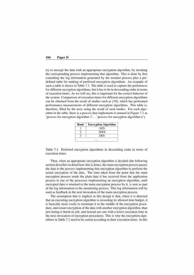
104 Paper D
try to encrypt the data with an appropriate encryption algorithm, by invokingthe corresponding process implementing that algorithm. This is done by firstconsulting the log information generated by the monitor process plus a pre-defined table for ranking of preferred encryption algorithms. An example ofsuch a table is shown in Table 7.1. The table is used to capture the preferencesfor different encryption algorithms, but it has to be in descending order in termsof execution times. As we will see, this is important for the correct behavior ofthe system. Comparison of execution times for different encryption algorithmscan be obtained from the result of studies such as [10], which has performedperformance measurements of different encryption algorithms. This table is,therefore, filled by the user, using the result of such studies. For each algo-rithm in the table, there is a process that implements it (named in Figure 7.1 as’process for encryption algorithm 1’. . . ’process for encryption algorithm n’).
Rank Encryption Algorithm1 AES2 3DES3 DES
. . .
Table 7.1: Preferred encryption algorithms in descending order in terms ofexecution times.
Then, when an appropriate encryption algorithm is decided (the followingsection describes in detail how this is done), the main encryption process passesthe data to the process implementing that encryption algorithm to perform theactual encryption of the data. The time taken from the point that the mainencryption process sends the plain data it has received from the applicationprocess to one of the processes implementing an encryption algorithm, untilencrypted data is returned to the main encryption process by it, is sent as partof the log information to the monitoring process. This log information will beused as feedback in the next invocation of the main encryption process.
The assumption that is implicit in this design is that, when it is detectedthat an executing encryption algorithm is exceeding its allowed time budget, itis basically more costly to terminate it in the middle of the encryption proce-dure, and restart encryption of the data with another encryption algorithm, thanjust letting it finish its job, and instead use one with a lower execution time inthe next invocation of encryption procedures. This is why the encryption algo-rithms in Table 7.1 need to be sorted according to their execution times. In this

7.3 Approach 105
way, the system first tries to encrypt all data with the algorithm at the top ofthe table. If it is observed that it cannot fulfill the specified time constraint, thesecond ranked algorithm (which has shorter execution time) will be chosen forencryption in the next invocation.
On the other hand, if an encryption algorithm completes its job sooner thanits specified time limit, the unused portion of its time budget is used to calculateand determine whether it is feasible to go back to the previous higher rankedalgorithm for the next encryption job or not. Using this approach, the systemtries to adapt itself based on the feedback it receives regarding its timing behav-ior. Therefore, when a burst of processing loads arrive, the system adapts itselfto this higher load, and when the processing load decreases, it can gradually goback to using more time-consuming (and presumably more secure) encryptionalgorithms. This is, for example, very useful in telecommunication systems,where lots of other services (than the one(s) using encryption) are active andneed to be responsive at the same time, where task pre-emption and contextswitches increase dramatically and interfere with the encryption job.
7.3.1 Log Information and Adaptation MechanismThe information that is logged by the monitor process has the following format:
Timestamp, Encryption algorithm, Time constraint, Actual execution timeAn Example of the generated log information is shown in Table 7.2.
10360, AES, 50, 9011800, 3DES, 80, 7014500, 3DES, 60, 7021353, DES, 60, 1022464, 3DES, 90, 4023112, AES, 50, 5028374, AES, 60, 58
Table 7.2: Sample log information.
The table shows that the system has first performed encryption using AESalgorithm, with a time constraint of 50 time units, but the actual execution timehas been 90; in other words, it has violated its time constraint. Therefore, inthe next execution, 3DES is automatically chosen for encryption (as it is thefirst lower ranked algorithm under AES in Table 7.1), which has finished itsjob in 70 time units while having 80 as its time constraint. Hence, no change

106 Paper D
in the encryption algorithm is observed and the same algorithm (3DES) is usedfor the third execution as well. The fifth and sixth rows in Table 7.2 (whichrepresent the fifth and sixth executions) show that the system has chosen toapply a higher ranked encryption algorithm (fourth to fifth: DES->3DES, andfifth to sixth: 3DES->AES).
In the log that is kept in memory from the log information generated aboveby the monitoring process, if an encryption algorithm is again selected for thenext invocation, its latest log record will replace the previous one. In otherwords, for each two consequent log records for a certain encryption algorithm,only the most recent one is kept. This is done to only keep the informationthat is necessary, which also leads to having only log information indicatingchanges of encryption algorithms being stored. Table 7.3, shows what is ac-tually necessary from the generated log information shown in Table 7.2, formaking adaptation decisions.
10360, AES, 50, 9014500, 3DES, 60, 7021353, DES, 60, 1022464, 3DES, 90, 4028374, AES, 60, 58
Table 7.3: Necessary portion of log information for making adaptation deci-sions.
Considering the last row from the log as:
ts, alg, t, e(ts: timestamp, alg: encryption algorithm, t: time constraint, e: actual execution time)
the decision that the system should adopt a lower ranked algorithm is madeusing the following formula:
(i) e > t ⇒ move down in the encryption algorithms table and select thenext algorithm with a lower rank.
Also, considering the two log records described as follows:ts(l), alg(l), t(l), e(l) : representing the last log record
ts(h), alg(h), t(h), e(h) : representing the log record for the first encryption al-gorithm with a higher rank that was used before the last log record
the decision to adopt a higher ranked algorithm is made using the followingformula:

7.3 Approach 107
(ii) e(l) < t(l)∧ t(l)− e(l) > abs(e(h)− t(h))⇒ move up in the encryp-tion algorithms table and select the previous higher ranked algorithm.
For example, in Table 7.3, applying formula (i) on row 1 (i.e., 90>50)shows that AES has taken more time than it was allowed to; therefore, a lowerranked algorithm (3DES) is used for the next invocation. However, for row 4,and the higher ranked algorithm just before it, which is AES at row 1, formula(ii) holds (i.e., 90-40>abs(90-50)); therefore, at the next invocation (corre-sponding to row 5), AES algorithm was used again.
7.3.2 Implementation DetailsThe implementation of the approach is done on OSE real-time operating sys-tems [5]. The OSE edition that is used is OSE Soft Kernel (OSE SFK), whichis a simulation of the actual environment to be downloaded to the target em-bedded hardware, and is possible to run on a host machine (e.g., on Windowsor Linux).
The execution unit in OSE corresponding to a real-time task is called pro-cess. For all the processes depicted in Figure 7.1, an OSE process is imple-mented. OSE offers two types of processes: static and dynamic. Static pro-cesses are created upon system startup, cannot be terminated, and last as longas the system is up and running. On the other hand, dynamic processes canbe created and killed on the fly by another process using OSE APIs. Mainapplication, main encryption process, and monitoring process, are created asstatic processes. Each encryption algorithm is implemented as dynamic pro-cesses, which are, in turn, created by the main encryption process at runtime asneeded. This is just a design choice to reduce the number of active processesin the system, as encryption algorithms can also be well created as static pro-cesses, in which case, the overhead of creating them for each invocation willbe reduced, while increasing the total scheduling overhead and memory usageof the system.
An interesting feature of OSE is offering the concept of load module. Loadmodules are relocatable program units that can be loaded into a running systemand dynamically bound to that system. A loadable module can be uploaded,rebuilt, and quickly downloaded while the remainder of the system continuesto run [5]. A load module can be considered similar to Windows .exe or .dllfiles. Once installed, the program (consisting of one or more processes) thatthey contain, can be created and started. In the case of our system, this meansthat security designers can add new encryption algorithms to the system dy-

108 Paper D
namically or update them on the fly, while the system is active and running.Such a feature is very important in high-availability systems, where updatesand upgrades (e.g., patching security issues) should affect the up-time of thesystem to the least degree possible.
Also, the direct and asynchronous message passing mechanism in OSE,makes this real-time operating system a great choice for use in distributed sys-tems. This further facilitates the scalability of systems that are built on OSE.Data between processes are passed as signals using three basic OSE APIs forsignal passing: send, receive, and alloc (to create signals containing data). TheInter-Process Communication protocol (IPC) used in OSE, makes the locationof processes transparent to the user; meaning that no matter whether two pro-cesses are located on the same board or on different ones, the communicationbetween them is done using the same set of APIs and code. Using this feature,the proposed approach is implemented without the need to use shared mem-ory among processes. The communication between processes is implementedusing the three above-mentioned APIs. This brings along the possibility todeploy the processes shown in Figure 7.1 on different processors and boardswithout affecting the generality of the approach, which is important for highly-distributed real-time embedded systems such as telecommunication systems.
Using the aforementioned features, several signals have been defined forsynchronization, and to pass data between processes. For example, signal HIS-TORY INFO REQUEST is defined which is sent from the main encryptionprocess to the monitoring process to request log information. In case of receiv-ing this signal, the monitoring process sends last log record, and the log recordfor the first encryption algorithm with a higher rank, used before the last record,to the main encryption process using HISTORY INFO REPLY signal. Usingthis signaling mechanism also allows to deploy processes on different nodes ifneeded. This is possible since the necessary information to make adaptationdecisions such as the time it takes to encrypt is passed between processes aspart of the signals, making the actual location of processes in different nodesunimportant and transparent for the approach to work. The rank table for en-cryption algorithms is actually implemented using enumerations in C/C++ inthe main encryption process.
7.3.3 Evaluation
To test the behavior of the system, a tool called CPU Killer [11] was used tocreate desired percentage of CPU loads at desired times. Moreover, Optima,which is a debugging, profiling, and monitoring tool developed by Enea for

7.3 Approach 109
OSE, was also used to monitor and observe, in the form of graphs and tables,CPU usage levels at different system ticks from the startup of OSE. The systemwas run two times: once without having adaptation and the second time usingadaptation. At each time, CPU loads of 10%, 50%, 70%, and then back to50%, and 10% were applied. The results are shown in Figure 7.2.
Figure 7.2: Results of running the system with and without adaptation.
The columns for each log record identify: system time (ticks), encryptionalgorithm, time constraint (ticks), and actual execution time (ticks). As men-tioned in the previous section, an enumeration in the form of ”enum algorithms{ AES=1, THREEDES=2, DES=3 };” was used to represent the informationof Table 7.1 in the code. The logs are decorated here with additional marks tofacilitate explanation and understanding of the results.
In case I, where no adaptation was applied, AES (as number 1 in the sec-

110 Paper D
ond column) algorithm is constantly used for encryption. This is because thegoal is to provide the maximum level of security, and therefore, the systemis designed to prefer and choose the topmost encryption algorithm (wheneverpossible) from the table, which represents the strongest one. The system wasstarted while applying 10% CPU load, and as can be seen from the figure, en-cryption is done within its time constraint of 300 and no violation is observed.However, when CPU load is increased to 50%, encryption starts violating itstime constraint. Violations are marked with * mark in the figure. In case of thefirst violation, it can be seen that encryption was completed in 305 ticks whilethe time constraint is 300 ticks. Violations get worse (with more time margins)at 70% CPU load. It is only after going back to 10% CPU load, that encryptioncan meet its constraint again.
In the second case (II), where adaptation was used, it can be easily under-stood at the first sight that the number of violations have decreased. The firstviolation occurs when the CPU load is set to 50%, however, the system adaptsitself to this new load and uses 3DES (as number 2 in the second column),which helps the system to perform within its time constraint again. When CPUload is set to 70%, violations are again observed. Therefore, the system adaptsitself by using DES (as number 3 in the second column) instead of 3DES,to stay within the time constraint. Even using DES, the system still fails tomeet its constraint, however, within a smaller time margin. In spite of viola-tions, since no lower rank algorithm than DES was defined in this experiment,the system keeps using it as the last possible choice. When the CPU load isreduced back to 50%, using the two formulas described at the beginning ofthe section, the system realizes that it can go back to using a higher rankedalgorithm (3DES in this case; hence number 2 is again observed in the sec-ond column as the used algorithm) without causing any violations. Finally, byreducing the CPU load further to 10%, the systems goes back to using AESagain.
Two rows are marked with A (at time 2111 and 5950) to show anomalyin the results. The first one which shows a violation for AES algorithm under10% load, while previous rows show that it can meet its constraint under thisload. This can be due to some background services doing some work in thesystem at that point, which has affected AES to perform encryption as before,and thus, resulted in a violation. Or, it can be because of a relatively slowmovement of the slider in the CPU Killer application, which is used to raisethe CPU load to 50% manually, and thus resulting in the system working in aCPU load between 10% and 50% for a short while at that moment. This canalso be the reason for the anomaly observed in the next row marked with A (at
7.4 Discussion 111
time 5950). In this case, this row shows that DES has managed to completewithin its time constraint under 70% CPU load. While, it could not perform soin the previous rows related to this algorithm (having number 3 in the secondcolumn). This can again be because of the relatively gradual decrease of theCPU load from 70% to 50%, causing the system to work at some CPU load inbetween.
Also another interesting observation from this result is that, as the conse-quence of using adaption, more encryption jobs have been performed in thesecond case (II), under a shorter period of time.
7.4 Discussion
Our suggested approach and the way we implemented it, gives this flexibil-ity to have different time constraints for each invocation of encryption proce-dures. This may not, however, be needed in all systems, and only a fixed value(e.g., originating from a system level requirement) might seem to be enoughfor many situations, but other systems can well benefit from this flexibility.
The whole adaptation mechanism can also be used as an option; in thesense that, if a system detects certain patterns in CPU load variations and vio-lation of timing constraints in the applied encryption algorithm, it can turn onadaptation mechanism and let the system decide which encryption algorithm touse. Moreover, use of the suggested adaptation mechanism may be most bene-ficial when there are many requests for encryption and frequency of CPU loadchanges are such that they make the overhead of adaptation mechanism accept-able. On the other hand, if there are only a few encryption requests or thereare not big changes in CPU load (or the range of changes is very small andknown beforehand), using a fixed encryption algorithm may be more desirable(to remove the overhead cost of adaptation).
The security level of the system, originating from the choice of encryptionalgorithms, is actually determined by the list of encryption algorithms that de-signers choose to include in the described encryption algorithms table. So, forexample, if for a system only AES and 3DES are acceptable, the table can beconstructed using only these two algorithms. This also defines what is the rangeof strongest and weakest encryption algorithms that the system may be usingat any moment. Moreover, while we only focused on the algorithm itself, anddid not discuss key length or block length explicitly, these factors (even thenumber of rounds), where applicable, can easily be taken into account usingthe table. For example, instead of just having AES, we can put AES256 and

112 Paper D
AES128 as items in the table, to bring into picture the role of key length, andthe system will choose each when decided appropriate.
Providing adaptations on encryption algorithms, also automatically leadsto some sort of security through obscurity (note the famous quote of ”securitythrough obscurity is not security”) [12, 13]. One interesting topic that we leaveas a future direction of this work to be investigated, is that whether adaptivemechanisms, as the one described here, can lead to weaknesses in the sys-tem and facilitate the job of attackers. For instance, issues such as this canbe analyzed more throughly that if attackers get to know the details of adapta-tion mechanisms, they might force the system into adopting the lowest ranked(weakest) encryption algorithm by creating CPU loads, and making it easierfor themselves to break into the system.
7.5 Related Work
Designing security features for embedded systems has its unique challengesand requires specific engineering methods and considerations. These issueshave been the subject of many studies such as [14, 1, 2]. [14] and [1], focus onthese unique challenges of security in embedded systems in general, and dis-cuss them under the processing gap, battery gap, flexibility, tamper resistance,assurance gap, and cost titles. [14] also provides workload analysis of SSLprotocol, and examples for energy consumption of different ciphers, to discussand illustrate the impacts of security features in embedded systems. The vi-sion for security engineering of embedded systems in the scope of a project isdescribed in [2].
[15] and [10] are examples of works that study the impacts of securitymechanisms on specific aspects of a system. Measurement and comparisonof memory usage and energy consumption of different encryption algorithmson two different sensor nodes (MicaZ and TelosB motes) are performed anddiscussed in [15], and [10] offers performance and timing comparisons of en-cryption algorithms on two Pentium machines. The approach we proposed inthis paper, relies on the results from the performance and timing comparisonsof encryption algorithms as provided in the aforementioned study.
In this paper, an adaptive way to deal with the timing costs and require-ments on security mechanisms was introduced. It should, however, be men-tioned that there are other ways for taking into account these timing costs,which might suit very well other types of systems than discussed here. Insystems with less complexity which are analyzable, a static and non-adaptive

7.5 Related Work 113
structure can be designed (i.e., a fixed set of security features will be used allthe time e.g., to encrypt data). The idea we proposed in [4] is basically anexample of such approach and systems.
The use of adaptive approaches and feedback mechanism for better CPUutilization and task scheduling in dynamic systems, where execution times oftasks can change a lot at runtime, has also been the topic of many studies inthe real-time systems domain, such as [16]. One of the interesting works in thearea of security for real-time embedded systems which uses an adaptive methodis the study done in [17]. One difference between our work and [17] is that,there, the focus is on a set of periodic tasks with known real-time parameters,whereas, our main target is complex systems consisting of periodic, sporadicand aperiodic tasks. Therefore, the analysis and formulas they offered in thatwork may not be applicable or need to be extended to support the type of sys-tems we discussed here. Also, they consider the security level of the system asa QoS value explicitly, while in this paper, it is considered implicitly and left tothe user through the use of a sorted table for encryption algorithms. Moreover,the main adaptation component of the system in that work is key length, whilein our work it is the encryption algorithms that are adaptively replaced, and caneasily include key length or any other relevant parameters as well. One of theinteresting and close studies to our work is [18]. They basically use a similartype of adaptation mechanism as ours. However, the main focus in this workis on client-server scenarios using a database, and to manage performance oftransactions. Also, security level adjustment in this work is done periodicallyusing a security manager component, while in our method, adaptation mecha-nism executes per request and is not active when application has no request forencryption. Moreover, in that work, while security level switch is occurring,it can lead to use of an inappropriate encryption method by a client, which issolved by rejecting it, through passing several acknowledgment messages andrepeating the process. Therefore, synchronization and message loss due of outof order arrival of messages are problematic for the security manager, which ishandled by re-sending of data and applying other means.
As another approach for managing security in real-time systems, Tao Xieand Xiao Qin, has basically incorporated timing management of security mech-anisms as part of the scheduling policy and developed a security-aware sched-uler in [19].

114 Paper D
7.6 Conclusion and Future WorkIn this paper, we discussed security, as a non-functional requirement, in thedesign of real-time embedded systems, and particularly, how the choice of en-cryption algorithms, can affect timing requirements in these systems. An adap-tive approach for selection of encryption algorithms was suggested for systemswhich need to balance their services at runtime in order to achieve their timeconstraints. It was shown how the approach can help the system to react todifferent processing loads and perform its encryption procedures within thedefined time constraints. While, OSE RTOS was used as the base platformfor implementation of the approach, there is nothing that stops it from beingimplemented on other platforms.
In the suggested approach here, a gradual increase or decrease of the rankof encryption algorithms was used. In other words, in each adaptation step, thesystem chooses either the next higher or lower ranked algorithm. As a futurework, it can be evaluated how the approach would perform, if in each adapta-tion, the lowest or highest ranked algorithm was selected instead. For example,if it is observed that the system completes its encryption job earlier than itstime constraint, it jumps to the top of the rank table and chooses the highestranked algorithm for the next invocation. It would be interesting to study forwhich systems/situations, each of these methods work better and categorizesystems accordingly. Calculating the overhead of adaptation mechanisms andoptimizing them is also left as a future study.
Moreover, in this work we focused on complex systems with not muchinformation about timing properties of each individual task in the system toperform analysis. This situation was observed in the design of a telecommu-nication sub-system during our work in the CHESS project [20]. Accordingly,the approach that is suggested in this paper tries to improve satisfaction of tim-ing constraints of the system by keeping a history of the timing behavior ofthe system. There is room to improve the suggested adaptation mechanism bytaking into account more information about the system than was used here, andalso more knowledge about the task that requires encryption when available.
Another direction of this work is to introduce other factors besides time forperforming adaptations. These factors may include energy consumption, mem-ory usage, and even situations where a system is under attack. Moreover, it wasdiscussed whether and how adaptation mechanisms might actually help attack-ers to break more easily into a system. This issue can serve as an interestingtopic for more careful investigations.

Bibliography
[1] Paul Kocher, Ruby Lee, Gary McGraw, and Anand Raghunathan. Secu-rity as a new dimension in embedded system design. In Proceedings ofthe 41st annual Design Automation Conference, DAC ’04, pages 753–760, 2004. Moderator-Ravi, Srivaths.
[2] Sigrid Gurgens, Carsten Rudolph, Antonio Mana, and Simin Nadjm-Tehrani. Security engineering for embedded systems: the secfutur vision.In Proceedings of the International Workshop on Security and Depend-ability for Resource Constrained Embedded Systems, S&D4RCES ’10,pages 7:1–7:6, New York, NY, USA, 2010. ACM.
[3] Luiz Marcio Cysneiros and Julio Cesar Sampaio do Prado Leite. Non-functional requirements: From elicitation to conceptual models. In IEEETransactions on Software Engineering, volume 30, pages 328–350, 2004.
[4] Mehrdad Saadatmand, Antonio Cicchetti, and Mikael Sjodin. On gen-erating security implementations from models of embedded systems. InThe Sixth International Conference on Software Engineering Advances(ICSEA 2011), October 2011.
[5] Enea. The architectural advantages of enea ose in telecom applica-tions. http://www.enea.com/Templates/Landing.aspx?id=27011, Last Accessed: September 2011.
[6] Anders Wall, Johan Andersson, Jonas Neander, Christer Norstrom, andMartin Lembke. Introducing temporal analyzability late in the lifecycleof complex real-time systems. In Proceedings of RTCSA 03, February2003.
115

116 Bibliography
[7] S.E. Chodrow, F. Jahanian, and M. Donner. Run-time monitoring of real-time systems. In Real-Time Systems Symposium, 1991. Proceedings.,Twelfth, pages 74 –83, dec 1991.
[8] Mehrdad Saadatmand, Antonio Cicchetti, and Mikael Sjodin. Uml-basedmodeling of non-functional requirements in telecommunication systems.In The Sixth International Conference on Software Engineering Advances(ICSEA 2011), October 2011.
[9] Enea. http://www.enea.com, Last Accessed: September 2011.
[10] A. Nadeem and M.Y. Javed. A performance comparison of data encryp-tion algorithms. In First International Conference on Information andCommunication Technologies, ICICT 2005., pages 84 – 89, 2005.
[11] CPU Killer. http://www.cpukiller.com/, Last Accessed:September 2011.
[12] Rebecca T. Mercuri and Peter G. Neumann. Security by obscurity.In Commun. ACM, volume 46, New York, NY, USA, November 2003.ACM.
[13] Hissam S, Weinstock C., Plakosh D., Jayatirtha A. Perspectiveson open source. Software Engineering Institute, Carnegie Mel-long http://www.sei.cmu.edu/library/abstracts/reports/01tr019.cfm, Published: November 2001, Last Ac-cessed: September 2011.
[14] Srivaths Ravi, Anand Raghunathan, Paul Kocher, and Sunil Hattangady.Security in embedded systems: Design challenges. ACM Transactions onEmbedded Computing Systems (TECS), 3:461–491, August 2004.
[15] Jongdeog Lee, Krasimira Kapitanova, and Sang H. Son. The price ofsecurity in wireless sensor networks. In Journal of Computer Networks,volume 54, pages 2967–2978, New York, NY, USA, December 2010.Elsevier North-Holland, Inc.
[16] Nima Moghaddami Khalilzad, Thomas Nolte, Moris Behnam, andMikael Asberg. Towards adaptive hierarchical scheduling of real-timesystems. In 16th IEEE International Conference on Emerging Technolo-gies and Factory Automation (ETFA’11), September 2011.

[17] Kyoung-Don Kang and Sang H. Son. Towards security and qos optimiza-tion in real-time embedded systems. In SIGBED Rev., volume 3, pages29–34, New York, NY, USA, January 2006. ACM.
[18] Sang H. Son, Robert Zimmerman, and Jorgen Hansson. An adaptablesecurity manager for real-time transactions. In Euromicro Conference onReal-Time Systems, pages 63–70, 2000.
[19] T. Xie and X. Qin. Scheduling security-critical real-time applications onclusters. In IEEE Transactions on Computers, volume 55, pages 864 –879, july 2006.
[20] CHESS Project: Composition with Guarantees for High-integrity Embed-ded Software Components Assembly. http://chess-project.ning.com/, Last Accessed: August 2011.


Chapter 8
Paper E:The Role of Schedulers inModel-Driven Developmentof Real-Time Systems
Mehrdad Saadatmand, Mikael Sjodin and Naveed Ul MustafaMRTC report, ISSN 1404-3041 ISRN MDH- MRTC-264/2012-1-SE,Malardalen Real-Time Research Centre, Malardalen University, March, 2012.
119

Abstract
Design of real-time embedded systems is a complex and challenging task.Model-driven development has the potential to reduce the design complexity ofreal-time embedded systems by increasing the abstraction level, enabling anal-ysis at earlier phases of development, and automatic generation of code fromthe models. In this context, capabilities of schedulers as part of the underly-ing platform play an important role. They can affect the complexity of codegenerators and how the model is implemented on the platform. Also, the waya scheduler monitors timing behaviors of tasks and schedules them can facil-itate extraction of runtime information. This information can then be used asfeedback to the original model in order to identify parts of the model that mayrequire to be re-designed and modified. In this paper, we describe our workin providing these features by introducing a second layer scheduler on top ofOSE real-time operating system’s scheduler. The approach can also contributeto the predictability of systems by bringing more awareness to the schedulerabout the type of real-time tasks (i.e., periodic, sporadic, and aperiodic) thatare to be scheduled, and the information that should be monitored and loggedfor each type.

8.1 Introduction 121
8.1 Introduction
Model-Driven Development (MDD) is a promising approach to cope with thedesign complexity of real-time embedded systems. It helps to raise the abstrac-tion level and also perform analysis at earlier phases of development. There-fore, problems in the design of a system can be identified before the implemen-tation phase [1].
Automatic code generation is also one of the end goals in model-drivendevelopment. In the context of real-time systems, this means generation ofperiodic, sporadic and aperiodic tasks. However, most (industrial) Real-TimeOperating Systems (RTOS) such as VxWorks, RTEMS, RT-Linux, WindowsCE, OSE, and FreeRTOS do not explicitly support the definition of differenttypes of real-time tasks (i.e., periodic, sporadic, and aperiodic) and specifica-tion of timing properties for them including period, deadline, Worst-Case Exe-cution Time (WCET), etc. While in theory, a real-time task is simply specifiedby its timing parameters, in practice and when it comes to implementations,these parameters are introduced in the system in different ways. For example,a periodic task may be implemented in the form of an interrupt while its periodis actually set by having a timer to trigger the interrupt periodically. For codegeneration, this means that for every model element defined as periodic, whatis actually generated is an interrupt handler that behaves in a periodic way.Therefore, when we look at these systems at runtime, no tangible and singlerunnable entity as a real-time periodic task is actually observed. In other words,the semantic mapping of a periodic task at model level and such an entity atruntime becomes weak.
Moreover, other parameters of a real-time task, such as deadline, are lostand not present at the implementation level, or taken into account and definedin arbitrary and different ways in each implementation. This is because amongall these parameters, what is usually supported explicitly by most real-timeoperating systems, is to specify only priority for a task. Other parameters areleft to be defined and implemented by system designers in arbitrary ways, suchas using timer interrupts and delays to enforce periodicity or Minimum Inter-Arrival Time (MIAT). The problem becomes even more evident when it comesto runtime monitoring of real-time systems and where a system needs to detectevents such as deadline misses, execution time overruns, etc.
To cope with these problems, we propose a second layer scheduler whichtakes as input specification and implementation of real-time tasks, includingall of their temporal parameters, and schedules and executes them using theunderlying scheduler of the operating system. With this design, the code gen-

122 Paper E
erators can then generate tangible real-time tasks according to a well-definedspecification (e.g., definition of a task as: task(task type, period, deadline, exe-cution time)), regardless of whether, for instance, they are going to be actuallyimplemented as a timer interrupt or some other mechanism. This way, an ac-tual real-time task along with its parameters will be present and identifiable atthe code level. The top-level scheduler schedules the task and uses its param-eters to manage and report events such as deadline misses or execution timeoverruns. In this approach, even if the underlying platform changes and imple-mentation of real-time tasks (e.g., as timer interrupt) are modified, it will notrequire any changes in the code generators, and also specification of real-timetasks. This improves the portability of the generated code and transformationengines, making them as platform-independent [2] as possible.
In this work, we highlight the role of schedulers in model-driven develop-ment of real-time systems and how they fit and contribute to different phasesof this approach. We also describe the suggested second layer scheduler webuilt on OSE real-time operating system [3], and demonstrate how it improvesmonitoring the timing behaviors of tasks at runtime and detecting events suchas deadline misses which are critical in real-time systems.
The remainder of the paper is as follows. In Section 8.2, we discuss thebackground context and motivation of the work. Section 8.3 describes the pro-posed approach along with its design and implementation details. In Section8.4, an example is demonstrated and the implementation and behavior of thesuggested approach is evaluated. In Section 8.5 we have a look at the relatedwork, and finally in Section 8.6, we summarize the work and describe its futureextensions and directions.
8.2 Background and Motivation
8.2.1 CHESS Project
This work has been done in the context of CHESS European project [4]. Thisproject is about model-driven and component based development of real-timeembedded systems for telecommunication, space, railway, and automotive do-mains which focuses on preservation and guarantee of extra-functional proper-ties [5]. This is done by performing static analysis on design models and mon-itoring the behavior of the generated system at runtime. The idea is to back-annotate monitored results back to the model to inform the designer whichmodeled features have led to the violation of specified requirements and may
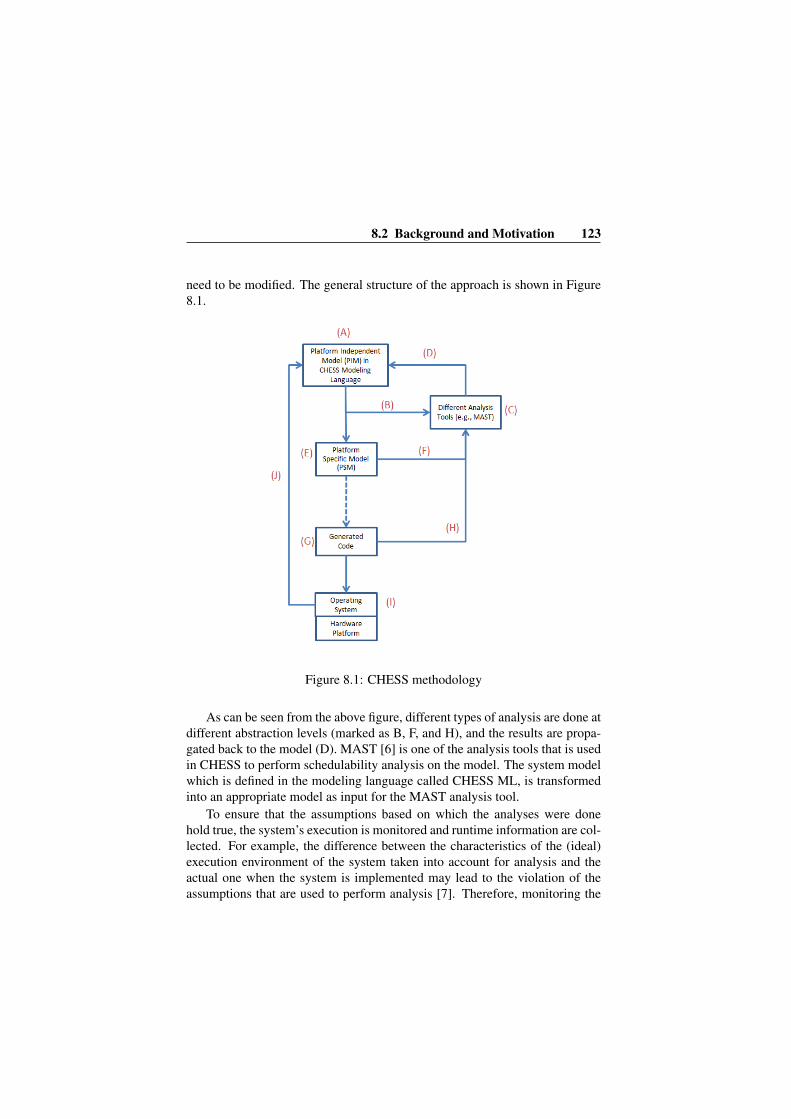
8.2 Background and Motivation 123
need to be modified. The general structure of the approach is shown in Figure8.1.
Figure 8.1: CHESS methodology
As can be seen from the above figure, different types of analysis are done atdifferent abstraction levels (marked as B, F, and H), and the results are propa-gated back to the model (D). MAST [6] is one of the analysis tools that is usedin CHESS to perform schedulability analysis on the model. The system modelwhich is defined in the modeling language called CHESS ML, is transformedinto an appropriate model as input for the MAST analysis tool.
To ensure that the assumptions based on which the analyses were donehold true, the system’s execution is monitored and runtime information are col-lected. For example, the difference between the characteristics of the (ideal)execution environment of the system taken into account for analysis and theactual one when the system is implemented may lead to the violation of theassumptions that are used to perform analysis [7]. Therefore, monitoring the
124 Paper E
behavior of the system at runtime is important in preservation of system prop-erties.
Timing properties are of utmost importance in real-time embedded sys-tems. In order to extract and collect information about runtime timing behav-iors for back-annotation to the model, the platform should be able to providethis information. Among the most important timing data for back-annotationthat are of interest are deadline misses, actual response time, and executiontime overruns. However, such a feature is not present explicitly in many com-mercial real-time operating systems today and needs to be implemented in dif-ferent ways by system developers. In the scope of this work, we narrow ourfocus on Part I of Figure 8.1.
8.2.2 OSE Real-Time Operating System
OSE is a real-time operating system developed by Enea [8]. It has been de-signed from the ground up for use in fault-tolerant distributed systems that arecommonly found in telecommunication domain, ranging from mobile phonesto radio base stations and is embedded in millions of devices around the world[3]. It provides preemptive priority-based scheduling of tasks. OSE offersthe concept of direct and asynchronous message passing for communicationand synchronization between tasks, and OSE’s natural programming model isbased on this concept. Linx, which is the Interprocess Communication Proto-col (IPC) in OSE, allows tasks to run on different processors or cores, utilizingthe same message-based communication model as on a single processor. Thisprograming model provides the advantage of not needing to use shared mem-ory among tasks.
The runnable real-time entity equivalent to a task is called process in OSE,and the messages that are passed between processes are referred to as signals(thus, the terms process and task in this paper can be considered interchange-ably). Processes can be created statically at system start-up, or dynamicallyat runtime by other processes. Static processes last for the whole life time ofthe system and cannot be terminated. Types of processes that can be created inOSE are: interrupt process, prioritized process, background process, and phan-tom process. One interesting feature of OSE is that the same programmingmodel is used regardless of the type of process. Of the timing properties thatwe have been discussing so far, only priority can be assigned for prioritizedprocesses. Periodic behavior can be implemented by using timer interrupt pro-cesses. Information such as task completion time, deadline misses and such, isnot reported by default and it needs to be implemented using system level APIs

8.2 Background and Motivation 125
for events such as process swap in and swap out which are triggered when aprocess starts and stops running (i.e., context switches).
8.2.3 GoalFigure 8.2 shows the target system that is built in the scope of this work. Asdiscussed before, most real-time operating systems, such as OSE, only allowspecification of priority for real-time tasks. In other words, semantically, thereis no parameter or kernel level value that represents deadline, execution time,or period of a task. Similarly, the monitoring information and logs that aregenerated by the system do not contain information about deadline misses, orexecution time overruns, because these concepts are not actually understoodby the kernel and have no meaning for it. Therefore, it is the job of a program-mer to implement such features and collect information by also implementingevent handlers that monitor when a task gets CPU time and when it is pre-empted, and then calculate deadline misses or execution time overruns throughthis information.
The proposed solution that is shown in Figure 8.2 solves this situation byintroducing a second layer scheduler. The interface to this scheduler layerrepresenting the specification of a real-time task is in the form of: Task(releasetime, period/MIAT, execution time, relative deadline, task type). Consideringthese parameters, the second layer scheduler then schedules the tasks using thepriority-based scheduling mechanism of the core scheduler.
The code generator on the other hand, generates real-time tasks (from themodel) according to this specification, and need not care how such a task isactually implemented on the core scheduler, hence more portability and re-usability of the analyzed model and generated code are obtained.
From the monitoring perspective, since the second layer scheduler is re-sponsible for scheduling tasks according to the described specification, it isaware of concepts such as deadline, and can therefore, produce log informa-tion representing events such as deadline misses. This generated log informa-tion from the second layer scheduler can then be used to propagate necessaryinformation back to the model.
We believe that the suggested added layer in our approach can also helpwith decreasing the gap between theoretical aspects of real-time systems andtheir actual implementations by providing more semantics to parameters andspecifications of real-time tasks at implementation level and thus increasingthe applicability of theoretical knowledge such as schedulability analysis tech-niques.

126 Paper E
Figure 8.2: Interfaces between different parts in the suggested approach
8.3 Scheduler Design and Implementation
In this section, the internal mechanism and design details of the second layerscheduler are described.
The second layer scheduler developed on top of OSE, schedules a given setof tasks (S) by releasing tasks to OSE core scheduler according to a selectedscheduling policy. S can contain three kinds of tasks: Periodic, Sporadic, andAperiodic tasks. Task parameters such as period and execution time are gen-erated for the second layer scheduler from the model as input parameter fileswith .prm extension.
As shown in Figure 8.3, the system consists of a few other componentsbesides the second layer scheduler process.
At system startup, first process creator is started. Process creator createsan OSE process for each of the tasks that are specified as a set of input files.

8.3 Scheduler Design and Implementation 127
Figure 8.3: Components of The Design
Initially, all these processes will be in the waiting mode (to receive a signalfrom the second layer scheduler process). From this point on, the second layerscheduler process, which has the highest priority in the system, controls thesystem. Based on a specified scheduling policy (e.g., EDF), the second layerscheduler selects an appropriate task from the queue of waiting tasks, and sendsa start signal to it. It then enters a waiting state itself using OSE receive w tmo(receive with timeout) system call. This system call makes the caller processwait until it either receives a signal or the specified timeout expires. We make a

128 Paper E
specific use of this system call in our design by setting its timeout value equalto the time interval available before arrival of a new instance of a higher priorityperiodic task. Also, whenever a task finishes execution, it sends a completionsignal back to the second layer scheduler process. Therefore, if the runningtask finishes its job before arrival of the next instance of a higher priority pe-riodic task, the second layer scheduler will receive a completion signal (at thereceive w tmo system call), and continues its job (scheduling next tasks). Oth-erwise, if the running task takes too much time, the timeout which is set in thereceive w tmo command in the second layer scheduler will expire, and sincethe second layer scheduler process has the highest priority in the system, it pre-empts the running task, takes the CPU, checks the list of waiting tasks again,and selects the next appropriate task to run.
Right after receiving the completion signal by the second layer schedulerprocess, it generates log information about the behavior of the task which hasjust completed. Since the second layer scheduler has access to (and thus isaware of) all the real-time parameters of each task (e.g., periodic/MIAT, dead-line, execution time), it can gracefully detect deadline misses, execution timeoverruns, and events of this kind, mark them in the log information and reportthem. This way, all this critical log information about the behavior of the sys-tem are also centralized, which can then be easily queried. This is an importantfeature which is absent in many real-time operating systems today.
Creation of monitoring log files and persistence of the collected informa-tion are done by the monitor process using the information that is sent to itby the second layer scheduler process in the form of signals. In this design,two separate log files are actually created: scheduling log file, and monitoringlog file. Scheduling log file contains listing of schedules generated by the sec-ond layer scheduler by stating the time points at which a task in the task set isscheduled, completed or preempted. This log file is generated by the secondlayer scheduler. Events related to task deadlines can be investigated by exam-ining the monitoring log file generated by the scheduler. Monitoring log file isupdated with new information only when an instance of a task is completed,and scheduling log file is updated whenever a task is scheduled, preempted,resumed or completed.
The scheduling policy that the second layer scheduler uses for periodictasks is selectable and not fixed. Same is the case with the scheduling mech-anism for aperiodic and sporadic tasks. The selected policy is read as a con-figuration value at system startup. This makes the suggested approach flexi-ble. Currently Rate Monotonic Scheduling (RMS) and Earliest Deadline First(EDF) policies are supported for periodic tasks while aperiodic and sporadic

8.3 Scheduler Design and Implementation 129
tasks can be scheduled using background [9] or polling server [9, 10] schemes.Other policies can also be added to design.
In the following sections, the role of different components in our design aredescribed in detail.
8.3.1 System ComponentsProcess Creator
Each task in a task set is specified by two files.
• Parameter File: A file with .prm extension provides task parameters in-cluding release time, period/MIAT, execution time, relative deadline andtype of the task.
Type of task can have four valid values. Different task types and the val-ues by which, each task type is represented in the system are mentionedin Table 8.1.
Task Type ValuePeriodic 0Sporadic 1Aperiodic 2
Polling Server 3
Table 8.1: Values for different task types
• Body File: A file with .c extension contains the body of the task. In otherwords, .prm file of a task contains its timing non-functional specificationwhile .c file contains its functional implementation.
Process creator reads the parameters for each task from its .prm file intoa data structure, called ”constraints”, and creates a prioritized OSE processagainst each user defined task. Moreover, It also creates following four OSEprioritized processes:
• Second layer scheduler process
• Sporadic queue holding process

130 Paper E
• Aperiodic queue holding process
• Monitor process
None of the created OSE processes is started by process creator except thesecond layer scheduler process. Task parameters and Process Identifiers (PIDs)for all processes are then passed to the second layer scheduler in the form of“constraints” data structure.
Second Layer Scheduler
After receiving “constraints” structure and PIDs of all OSE processes createdby process creator, the second layer scheduler schedules the tasks by releasingthem to core OSE scheduler according to selected scheduling algorithm. Thedesign provides options to select between RMS or EDF algorithm.
To schedule sporadic and aperiodic tasks, the second layer scheduler sup-ports background scheduling and polling server for scheduling sporadic andaperiodic tasks.
Sporadic Queue Holder
Task set can contain periodic, aperiodic and sporadic tasks. Sporadic queueholder is a prioritized OSE process which maintains a list of sporadic taskswaiting for scheduling, by using a queue. Each element of queue contains twoparameters for a sporadic task: PID corresponding to the given task, and re-lease time of sporadic task.
To release a sporadic task, its PID and release time is to be placed in queue.An interrupt process (in case of hardware driven sporadic tasks) or a prioritizedprocess (in case of software driven sporadic tasks) may initiate this placementby sending a signal to sporadic queue holder.
Upon receiving this signal, sporadic queue holder extracts the PID and re-lease time of sporadic task from signal and updates the queue with extractedinformation.
The second layer scheduler checks if there is a sporadic task to be sched-uled by making a query to sporadic queue holder process.
Aperiodic Queue Holder
Aperiodic queue holder has the same structure and mechanism as the sporadicqueue holder, except that it maintains a list of aperiodic tasks. Also separatesignals are defined for use with aperiodic and sporadic queue holders.

8.3 Scheduler Design and Implementation 131
Monitor
Monitor process generates a log file to state whether specified timing con-straints for each task in task set S are met or not. For example, if the specifiedMIAT parameter, in case of a sporadic task, is violated then monitor recordsthis violation in a monitoring log file.When a task is released to the core OSE scheduler for execution, the secondlayer scheduler observes its timing parameters. As soon as a task completesits execution, the second layer scheduler sends a signal to the monitor process.This signal contains start time, completion time, desired deadline, desired ex-ecution time, desired MIAT, actual execution time, and actual MIAT of com-pleted task. These timing values are extracted from .prm file of the task undermonitoring (i.e., desired deadline and execution time) and measured by the sec-ond layer scheduler (i.e., actual deadline and execution time). Monitor extractsthese timing values from the received signal and saves the relevant monitoringstatements in a monitoring log file.
8.3.2 Signals and CommunicationsTo achieve the scheduling of tasks in a reliable way, several signals are definedand used by system. These signals play two important roles: carry requireddata from one component to another, and ensure synchronous execution of allcomponents.
These signals are described below.
• start exe sig: Start execution signal. This signal is sent by the secondlayer scheduler to a process to be scheduled on core OSE scheduler.Target process can start execution only if it has received start exe sigsignal.
• comp sig: Completion signal. This signal is sent as an acknowledgmentto the second layer scheduler upon completion by a process which iscreated against a user defined task.
• aper update sig: Update signal for aperiodic queue holder. To releasean aperiodic task, an interrupt process or prioritized process sends theaper update sig signal to aperiodic queue holder process. This signalcontains the PID and release time of an aperiodic task to be scheduled.This signal is also used as a response to the second layer scheduler byaperiodic queue holder on receiving start exe sig from scheduler.

132 Paper E
• spor update sig: Update signal for sporadic queue holder. To releasea sporadic task, an interrupt process or prioritized process sends thespor update sig signal to sporadic queue holder process. This signal con-tains the PID and release time of sporadic task to be scheduled.This signal is also used as a response to the second layer scheduler bysporadic queue holder on receiving start exe sig from scheduler.
• qupdate confirm sig: Queue update confirmation signal. This con-firmation signal is sent back to the sender of an update signal, af-ter receiving aper update sig (in case of aperiodic queue holder) orspor update sig (in case of sporadic queue holder). Confirmation sig-nal informs sender if queue is updated successfully. In case of failure,sender can send aper update sig again with same content after waitingfor a finite amount of time.
• monitor info sig: Monitoring information signal. This signal is sent bythe second layer scheduler to the monitor, every time a task completesits execution. Monitor uses the information contained in this signal todetermine if a completed task has met its constraints, such as deadlineand WCET.
8.3.3 Priority AssignmentIn OSE, there are 32 priority levels. Priority 0 is considered the highest while31 is considered as the lowest priority level. In our system, process creatorcreates one OSE process for each task in the input task set. All such processesare assigned priority level of 1. Similarly, sporadic queue holder process andaperiodic queue holder process have priority level of 1. However, the secondlayer scheduler process has priority level of 0 which is the highest possiblepriority level. The reason for assigning priority level 0 to the scheduler is tomake it non preemptable by any other prioritized OSE process.
Monitor behaves as a background OSE process and hence has the lowestpriority level. This ensures that monitoring is performed only when no task isready and the scheduler is idle. This reduces the effect of monitoring on thescheduling of tasks.
8.3.4 Scheduling of TasksAs described in the previous section, all OSE processes are created by Processcreator but not started by it. Process creator starts only the second layer sched-

8.3 Scheduler Design and Implementation 133
uler process and passes “constraints” structure along with PIDs of all OSEprocesses.
Scheduling of Periodic Tasks
The second layer scheduler examines the “type” parameter of all tasks to iden-tify periodic tasks among the task set. Tasks are scheduled by releasing them tocore OSE scheduler according to specified scheduling algorithm, for exampleRMS.
The second layer scheduler sends start exe sig to the the process repre-senting the user defined task which has highest priority according to selectedscheduling algorithm. Then scheduler waits for receiving comp sig back fromtarget OSE process but with a finite waiting time called “timeout”.
If comp sig is received before the timeout is expired, it implies that thetarget process has completed. Hence the second layer scheduler releases to thecore OSE scheduler the next ready OSE process representing the user definedperiodic task. If comp sig is not received within the timeout duration and aprocess representing a user defined task with higher priority is ready, then theformer process is preempted and second layer scheduler releases to core OSEscheduler the process with higher priority.
Scheduling of Sporadic and Aperiodic Tasks
To schedule a sporadic task, it is necessary that its corresponding PID andrelease time are placed in the sporadic processes queue maintained by sporadicqueue holder. This can be achieved by sending a spor update sig signal to thesporadic queue holder containing release time and PID of the OSE processcorresponding to the task. Signal, spor update sig, can be sent to the sporadicqueue holder either by an interrupt OSE process or a prioritized OSE process.In the first case, target sporadic task becomes interrupt driven while in secondcase it behaves as a program driven sporadic task. The above discussion isvalid also for achieving interrupt and program driven behavior for aperiodictasks.
Sporadic and aperiodic tasks can be scheduled by using one of followingtwo approaches:
• Background Scheme: One approach to schedule sporadic and aperiodictasks is to use time slots in which no periodic task is ready to run. Insuch case, the second layer scheduler first makes query to sporadic queue

134 Paper E
holder by sending start exe sig to find if there is any ready sporadic task.The spor update sig signal is sent back by sporadic queue holder to thesecond layer scheduler, indicating availability status of sporadic task.If there is a ready sporadic task, the second layer scheduler releases spo-radic task to OSE core scheduler and waits until either it completes itsexecution or a periodic task becomes ready. If sporadic task is completedand no periodic task is ready to run, second layer scheduler again makesquery to sporadic queue holder to find if there are any more sporadictasks waiting in the queue.If sporadic task queue is empty and no periodic task is ready to run, thesecond layer scheduler makes query to aperiodic queue holder by send-ing start exe sig. Availability status of aperiodic task is communicatedback to the second layer scheduler by sending aper update sig from ape-riodic queue holder. If aperiodic queue is not empty and aperiodic task atthe head of the queue is ready to run, the second layer scheduler releasesthat aperiodic task to core OSE scheduler.If there is no periodic, sporadic and aperiodic task to execute, Monitorprocess is released to core OSE scheduler by the second layer scheduler.
• Polling Server Scheme: An alternative approach to schedule sporadicand aperiodic tasks is to use polling server. Polling server is a periodictask like any other periodic task. It has a period Ps and execution timeEs. Execution time of polling server is known as its budget.Polling server is scheduled along with all other periodic tasks accordingto selected scheduling algorithm. However, when polling server gets thechance to execute, the second layer scheduler makes query to sporadicand aperiodic queue holding processes to find if there is any ready spo-radic or aperiodic task. If sporadic or aperiodic task is ready to run, thesecond layer scheduler releases that task to OSE core scheduler and bud-get of polling server keeps declining per unit time.If sporadic or aperiodic task completes its execution before budget is ex-pired, the second layer scheduler picks next ready sporadic or aperiodictask to release to OSE core scheduler. This sequence continues until ei-ther there is no sporadic or aperiodic task or budget of server is expiredor a higher priority periodic task becomes ready to execute.At the start of each period of the polling server, its budget is set equalto its execution time. If at that time point, no sporadic or aperiodic taskis ready to run then budget immediately declines to zero. Otherwise thebudget decreases one level per time unit.

8.3 Scheduler Design and Implementation 135
8.3.5 Monitoring of TasksOn completion of a task, independent of its type, the second layer schedulersends monitor info sig signal to Monitor. Monitor is implemented as a back-ground OSE process. Hence, it can execute only when there is no periodic,sporadic or aperiodic task ready to run. Monitor continuously checks its in-put message queue for monitor info sig signal. This message carries followinginformation to the monitor process regarding completed task:
• start time of the task
• completion time of the task
• specified deadline parameter for the task
• specified MIAT parameter for the task
• specified execution time for the task
• actual execution time for task
• actual deadline for task
• actual MIAT for the task
Monitor uses this information to make decision if a completed task has met itsparameters or violated them. In any case, monitor records the information in amonitoring log file.
Operation of the scheduler is summarized by the sequence diagram of Fig-ure 8.4. In this diagram, the task set consists of two periodic tasks T1 and T2,one sporadic task T3 and an aperiodic task T4. Timing parameters of the tasksdefined in this task set are listed below using the specification convention: Task(Release Time, Period, WCET, Relative deadline, Task type).
Periodic task: T1(0, 12, 3, 8, 0)Periodic task: T2(0, 4, 1, 3, 0)
Sporadic task: T3(0, 15, 2, 6, 1)Aperiodic task: T4(0, 0, 1, 6, 2)
This figure shows a valid sequence of execution when RMS is used as thescheduling policy for periodic tasks, while sporadic and aperiodic tasks arescheduled using background scheme. As is evident from the sequence diagram,monitor gets the chance to execute only when no other process is in ready state.

136 Paper E
Figure 8.4: Sequence diagram to demonstrate operation of the scheduler
8.4 Experiment and Monitoring Results
The described approach has been implemented and tested on OSE SoftKernel(SFK) version 5.5.1 [8]. In this section, we show an example of a task setwhich is implemented based on the specification of the proposed second layerscheduler. The way the task set is scheduled and the log information that isgenerated for the behaviour of tasks are illustrated.
A task set consisting of four tasks is created. Periodic tasks in the taskset are configured to be scheduled using RMS while aperiodic and sporadictasks are to be scheduled using polling server scheme (this can be changed bychanging configuration parameters).

8.4 Experiment and Monitoring Results 137
Timing constraints for tasks are given below (last parameter identifies thetype of task):
• T1(0, 10, 2, 5, 3) : Polling server with release time=0, period=10,WCET/Budget=2, Relative Deadline=5, Task type=3.
• T2(0, 5, 2, 4, 0) : Periodic Task with release time=0, period=5,WCET=2, Relative Deadline=4, Task type=0.
• T3(0, 5, 2, 4, 1) : Sporadic Task with release time=0, MIAT=5,WCET=2, Relative Deadline=4, Task type=1. Two instances of Spo-radic task T3 are released at time 0;
• T4(0, 0, 2, 7, 2) : Aperiodic Task with release time=0, period= 0 (NotApplicable), WCET=2, Relative Deadline=7, Task type=2.
As mentioned before, these timing parameters are actually specified in the.prm file of each task (i.e., t1.prm, . . . , t4.prm). Process creator opens thesefiles and populates ”constraints” data structure with these data.
Using the implemented second layer scheduler to schedule this task set, thefollowing log files are automatically generated:
• Scheduling log file: Scheduling log file provides the time points foreach task at which it is scheduled, preempted/not completed, resumed orcompleted. Parts of the scheduling log information generated for the taskset are shown in Listing 8.1. To make it easier to follow and understandthe information in the log file, the PIDs that are assigned to each task bythe system are also mentioned below:
– PID of process representing T1 = 65595.
– PID of process representing T2 = 65596.
– PID of process representing T3 = 65597.
– PID of process representing T4 = 65598.
Listing 8.1: Scheduling log filet a s k PID=65596Schedu led f o r 5 t i c k s a t t i c k s =1115t a s k PID=65596Completed a t t i c k s =1117t a s k PID=65597Schedu led wi th b udg e t = 2 t i c k s a t t i c k s =1117t a s k PID=65597

138 Paper E
Not comple t ed a t t i c k s =1119Remaining E x e c u t i o n Time i n t i c k s =1t a s k PID=65596Schedu led f o r 5 t i c k s a t t i c k s =1120t a s k PID=65596Completed a t t i c k s =1122t a s k PID=65596Schedu led f o r 5 t i c k s a t t i c k s =1125t a s k PID=65596Completed a t t i c k s =1127t a s k PID=65597Resumed wi th bu dg e t = 2 t i c k s a t t i c k s =1127t a s k PID=65597Completed a t t i c k s =1128t a s k PID=65597Schedu led wi th b udg e t = 1 t i c k s a t t i c k s =1128t a s k PID=65597Not comple t ed a t t i c k s =1129Remaining E x e c u t i o n Time i n t i c k s =1t a s k PID=65596Schedu led f o r 5 t i c k s a t t i c k s =1130t a s k PID=65596Completed a t t i c k s =1132t a s k PID=65596Schedu led f o r 5 t i c k s a t t i c k s =1135t a s k PID=65596Completed a t t i c k s =1137t a s k PID=65597Resumed wi th bu dg e t = 2 t i c k s a t t i c k s =1137t a s k PID=65597Completed a t t i c k s =1138t a s k PID=65598Schedu led wi th b udg e t = 1 t i c k s a t t i c k s =1138t a s k PID=65598Not comple t ed a t t i c k s =1139Remaining E x e c u t i o n Time i n t i c k s =1t a s k PID=65596Schedu led f o r 5 t i c k s a t t i c k s =1140t a s k PID=65596Completed a t t i c k s =1142
• Monitoring log file: On completion of each instance of a task, mon-itoring log file lists type of task, PID of process representing that taskin system, start time of the task, specified deadline, completion time ofthe task, specified WCET for the task, actual execution time consumedby the task, response time of the task, specified MIAT/period and actualinterval between two consecutive invocations of the task. Listing 8.2shows parts of the monitoring log information generated for the task set.
Listing 8.2: Monitoring log filePID =65596Type of t a s k =0s t a r t t ime i n t i c k s =1115

8.4 Experiment and Monitoring Results 139
s p e c i f i e d d e a d l i n e i n t i c k s =1119c o m p l e t i o n t ime i n t i c k s =1117s p e c i f i e d WCET i n t i c k s =2a c t u a l e x e c u t i o n t ime i n t i c k s =2Response t ime i n t i c k s =2s p e c i f i e d P e r i o d / MIAT i n t i c k s =5I n t e r v a l be tween two c o n s e c u t i v e i n v o c a t i o n s i n t i c k s =5PID =65596Type of t a s k =0s t a r t t ime i n t i c k s =1120s p e c i f i e d d e a d l i n e i n t i c k s =1124c o m p l e t i o n t ime i n t i c k s =1122s p e c i f i e d WCET i n t i c k s =2a c t u a l e x e c u t i o n t ime i n t i c k s =2Response t ime i n t i c k s =2s p e c i f i e d P e r i o d / MIAT i n t i c k s =5I n t e r v a l be tween two c o n s e c u t i v e i n v o c a t i o n s i n t i c k s =5PID =65596Type of t a s k =0s t a r t t ime i n t i c k s =1125s p e c i f i e d d e a d l i n e i n t i c k s =1129c o m p l e t i o n t ime i n t i c k s =1127s p e c i f i e d WCET i n t i c k s =2a c t u a l e x e c u t i o n t ime i n t i c k s =2Response t ime i n t i c k s =2s p e c i f i e d P e r i o d / MIAT i n t i c k s =5I n t e r v a l be tween two c o n s e c u t i v e i n v o c a t i o n s i n t i c k s =5PID =65597Type of t a s k =1s t a r t t ime i n t i c k s =1117s p e c i f i e d d e a d l i n e i n t i c k s =1121c o m p l e t i o n t ime i n t i c k s =1128s p e c i f i e d WCET i n t i c k s =2a c t u a l e x e c u t i o n t ime i n t i c k s =3Response t ime i n t i c k s =11s p e c i f i e d P e r i o d / MIAT i n t i c k s =5I n t e r v a l be tween two c o n s e c u t i v e i n v o c a t i o n s i n t i c k s =10PID =65596Type of t a s k =0s t a r t t ime i n t i c k s =1130s p e c i f i e d d e a d l i n e i n t i c k s =1134c o m p l e t i o n t ime i n t i c k s =1132s p e c i f i e d WCET i n t i c k s =2a c t u a l e x e c u t i o n t ime i n t i c k s =2Response t ime i n t i c k s =2s p e c i f i e d P e r i o d / MIAT i n t i c k s =5I n t e r v a l be tween two c o n s e c u t i v e i n v o c a t i o n s i n t i c k s =5PID =65596Type of t a s k =0s t a r t t ime i n t i c k s =1135s p e c i f i e d d e a d l i n e i n t i c k s =1139c o m p l e t i o n t ime i n t i c k s =1137s p e c i f i e d WCET i n t i c k s =2a c t u a l e x e c u t i o n t ime i n t i c k s =2Response t ime i n t i c k s =2s p e c i f i e d P e r i o d / MIAT i n t i c k s =5I n t e r v a l be tween two c o n s e c u t i v e i n v o c a t i o n s i n t i c k s =5PID =65597

140 Paper E
Type of t a s k =1s t a r t t ime i n t i c k s =1128s p e c i f i e d d e a d l i n e i n t i c k s =1132c o m p l e t i o n t ime i n t i c k s =1138s p e c i f i e d WCET i n t i c k s =2a c t u a l e x e c u t i o n t ime i n t i c k s =2Response t ime i n t i c k s =10s p e c i f i e d P e r i o d / MIAT i n t i c k s =5I n t e r v a l be tween two c o n s e c u t i v e i n v o c a t i o n s i n t i c k s =9
The first four lines in the generated scheduling log information shown inListing 8.1 indicates that the periodic task T2 with PID of 65596, which isstarted at tick time 1115, has completed at 1117. The next task which is sched-uled is T3 with PID of 65597. The polling server has the capacity of two timeunit at this time instance, therefore, the sporadic task T3 can run until tick time1119, and at 1120 another instance of T2 arrives which causes the second layerscheduler to preempt T3. However, at 1119, T3 has not managed to completeits job, and therefore, it is marked as ’Not completed’.
On the other hand, the monitoring information in Listing 8.2, among otherthings, can be used to check whether any deadline miss has occurred or not. Forexample, it shows that the first two instances of T2 (PID=65596) have met theirdeadlines. The first instance has finished its job at 1117 and finished before itsdeadline which is 1119. The deadline for the second instance is at 1124, andit has managed to complete its job at 1122, and therefore, meet its deadline.However, the deadline of the sporadic task T3, with PID of 65597, has been1121 while it has managed to finish its job at 1128. Its actual execution timehas also been three time units which is one time unit more than its specifiedWCET. This shows that there has been execution time overrun for this task andthere is something wrong with the specified WCET value of it, and it needsto be re-considered. Such information are hardly provided by default in anyreal-time operating system.
Figure 8.5 visualizes the schedule generated by the scheduler. This figureis created (manually) using the information available in the scheduling log filegenerated by the scheduler. The scheduling log file shows that the first task isreleased at 1115 system ticks. To make this schedule easier to understand inthe figure, subtraction of 1115 ticks is performed at every time point.
As is indicated by a cloud symbol in Figure 8.5, actual execution time con-sumed by first instance of sporadic task is 3 ticks instead of 2 ticks as specifiedin timing constraint of WCET=2. Therefore, it misses its deadline of 5 ticksand is completed at 13 ticks. Second instance of sporadic task is scheduledimmediately after completion of the first instance. This is because MIAT of 10

8.5 Related Work 141
Figure 8.5: Schedule generated by the design using second layer scheduler
ticks is already elapsed (10+2=12). The diagram in the lower part of Figure 8.5indicates the replenishment and decrease of budget with passage of time as isdefined for the behavior of polling servers.
Now that the necessary information about the runtime behavior of tasks isprovided in the log files generated by the system, a user can easily query them,extract desired parts, and draw conclusions. For example, it is very easy to findout the number of deadline misses, execution time overruns, the task with max-imum number of deadline misses, etc. by using the log files as the data source.Similarly, at any time point, the number of periodic, sporadic, and aperiodictasks in the system can easily be requested from the second layer scheduler; asimple but important feature which is not provided by default in many RTOSestoday. Also, it is now possible to identify and report the time period duringwhich maximum number of deadline misses have occurred, and examine aswell how the system has been behaving in terms of context switches and pre-emptions during that period. These are features whose implementations can bevery hard and complex without having the necessary monitoring informationand using the suggested approach.
8.5 Related WorkMany of the operating systems and also programming languages today providesupport for measuring the CPU time a runnable entity (i.e., thread, etc.) con-sumes to perform its function. However, the monitoring facilities and eventhandling mechanisms provided by these platforms are not usually integrated

142 Paper E
with their scheduling facilities [11]. As a result, the platform cannot enforceand monitor real-time properties of threads such as their allowed executiontimes and deadlines. Real-Time Specification for Java (RTSJ) [11] is intro-duced to integrate scheduling of threads with the execution time monitoringfacilities and enforce execution budgets on them in Java.
The work described in [12] is an attempt to implement sporadic servers inAda. It also uses the concept of queues to manage sporadic and aperiodic tasksas we did here. However, it does not discuss real-time applications built onthis design and using these servers; i.e., how sporadic and aperiodic tasks aredefined and introduced to the system. [13], which also targets sporadic tasks inAda, highlights the problem that we mentioned in this paper which many real-time platforms suffer from. It states the issue by claiming that the underlyingkernel needs to provide complex execution time monitoring mechanisms atruntime and that ”such mechanisms are not generally supported by Ada 9X”.
One of the closest works to our approach is the implementation of a newscheduling class called SCHED DEADLINE for the Linux kernel that addsEDF scheduling policy support to Linux [14]. It is also motivated by acknowl-edging the fact that due to limited support for specifying timing constraints forreal-time tasks (e.g., deadline) and lack of control over them, feasibility studyof the system under development and guaranteeing the timing requirementsof tasks are not possible. There are however several differences between thiswork and ours. It focuses only on mechanisms for adding EDF scheduling pol-icy to the Linux kernel, while we target the problem in a more general mannerand allowing the scheduling policy to be configurable. Our focus is mainlyon improving the monitoring of real-time events by providing more controlover real-time tasks and more knowledge about their timing constraints to thescheduler regardless of the scheduling policy. Moreover, we try to provide anabstraction layer around the core scheduler to hide platform-dependent imple-mentation details from the user, while SCHED DEADLINE tries to solve adifferent problem and is basically added as a separate module to the system.
One concept which also introduces different levels of abstraction around acore scheduler is Hierarchical Scheduling Framework (HSF) [15, 10]. Thereare fundamental differences between what we introduced here and HSF. HSFis a modular approach in which a system is divided into several subsystems.The subsystems are scheduled by a global (core) scheduler, while the tasksin each subsystem are scheduled by local (sub-system) level schedulers. Thestructure that we introduced here does not try to divide a system into differentsubsystems where each of these subsystems may be scheduled differently by adifferent scheduler.

8.6 Discussion and Conclusion 143
There are also studies that focus on execution monitoring of real-time sys-tems. Many of these studies, such as [16], try to predict timing violationsin the system in different ways, for example, using statistical models. Oursuggested approach does not to try to predict violations and produces precisemonitoring information for behavior of real-time tasks and violation of timingconstraints. The monitoring part in our approach is coupled with the schedulerand by bringing awareness to the scheduler about the type of tasks it is schedul-ing, monitoring such information becomes a natural and straightforward partof the scheduler.
8.6 Discussion and Conclusion
In this paper, we introduced the concept of the second layer scheduler as an ap-proach to bring semantics and awareness for different types of real-time tasksand their parameters to the scheduler. It was shown how this awareness im-proves the monitoring capabilities of the system to help with the detection ofcritical events such as deadline misses, and execution time overruns. While theapproach was motived and described in the context of model-driven develop-ment of real-time systems, and how it can contribute to ease code generationand enable back-annotation of data, it does not necessarily need to be used inthis context and the concept of the second layer scheduler is applicable andpractical per se.
Considering a larger set of timing parameters for scheduling of tasks andgenerating detailed log information in the second layer scheduler can bringalong their own overheads. Measurement of these overheads and evaluation ofthe price of these added features are left to be done as a future work. Especiallywe plan to perform two overhead measurements: startup overhead (readingconfigurations and initializing tasks), and context switch and scheduling deci-sions overheads. It should however be noted that the actual logging is done bythe monitor process in our design which behaves as a background process. Thesecond layer scheduler only sends out a signal (including needed information)to the monitor process and continues its job (asynchronously) without usingany critical section for data sharing by using message passing mechanisms ofOSE. This way, the overhead of creating log information in the second layerscheduler process is tried to be mitigated.
Generation of such detailed monitoring information can also help with thepredictability of real-time systems at runtime. For instance, even in caseswhere no deadline misses occur in the system, it becomes possible to ob-

144 Paper E
serve how close tasks are to missing their deadlines and whether this gap isdecreasing or increasing. Based on such analysis of monitoring information,the system can also adapt itself in order to prevent deadline misses.
One issue that we did not discuss in this paper is the priority inversion prob-lem. This problem is handled automatically by OSE for communication amongperiodic tasks, but for sporadic and aperiodic tasks, the priority inversion issueshould be more investigated. Also the way the system is designed for the back-ground scheme, periodic tasks will have higher priority over sporadic tasks,and the priority of sporadic tasks will be higher than aperiodic ones. When thepolling server scheme is used, the priority of sporadic tasks will be dependenton the priority of their periodic server, but still higher than aperiodic ones. Thiscan also be extended to be configurable by the user. Moreover, in this work,since the tasks were assumed to be generated from a model, the task set wasconsidered to be known and static. We leave the extension of the implemen-tation to accept new tasks dynamically as a future work. Also, the possibilityto have different numbers and types of servers for sporadic and aperiodic taskscould be another future work.
Since the suggested approach is designed to be flexible in terms of theused scheduling algorithms, it would be interesting as a future direction ofthis work, to investigate the possibility to let the system intelligently selectan appropriate/optimal scheduling algorithm based on the requirements at themodel level, and generate code accordingly, especially that the back-annotationmechanism can also be used as a feedback loop.
8.7 AcknowledgementsThis work has been partially supported by the CHESS European Project(ARTEMIS-JU100022) [4] and Enea Services Stockholm AB [8].

Bibliography
[1] Bran Selic. The pragmatics of model-driven development. IEEE Soft-ware, 20:19–25, September 2003.
[2] A. Kleppe, J. Warmer, and W. Bast. MDA Explained: The Model DrivenArchitecture - Practice and Promise. 2003.
[3] Enea. The architectural advantages of enea ose in telecom applica-tions. http://www.enea.com/software/products/rtos/ose/, Last Accessed: February 2012.
[4] CHESS Project: Composition with Guarantees for High-integrity Embed-ded Software Components Assembly. http://chess-project.ning.com/, Last Accessed: February 2012.
[5] Luiz Marcio Cysneiros and Julio Cesar Sampaio do Prado Leite. Non-functional requirements: From elicitation to conceptual models. In IEEETransactions on Software Engineering, volume 30, pages 328–350, 2004.
[6] Modeling and Analysis Suite for Real-Time Applications (MAST).http://mast.unican.es/, Last Accessed: February 2012.
[7] S.E. Chodrow, F. Jahanian, and M. Donner. Run-time monitoring of real-time systems. In Real-Time Systems Symposium (RTSS). Proceedings.,Twelfth, pages 74 –83, dec 1991.
[8] Enea. http://www.enea.com, Last Accessed: February 2012.
[9] Brinkley Sprunt. Aperiodic task scheduling for real-time systems. Tech-nical report, Ph.D. thesis, Carnegie Mellon Univ, 1990.
145

[10] Robert Davis and Alan Burns. Hierarchical fixed priority pre-emptivescheduling. In In Proceedings of the 26 th IEEE International Real-TimeSystems Symposium (RTSS’05), pages 389–398, 2005.
[11] Andy J. Wellings, Gregory Bollella, Peter C. Dibble, and David Holmes.Cost enforcement and deadline monitoring in the real-time specificationfor java. In 7th IEEE International Symposium on Object-Oriented Real-Time Distributed Computing (ISORC), pages 78–85. IEEE Computer So-ciety, 12-14 May 2004.
[12] B. Sprunt and L. Sha. Implementing sporadic servers in Ada. Technicalreport. Carnegie Mellon University, Software Engineering Institute, 1990.
[13] A. Burns and A. J. Wellings. Implementing analysable hard real-timesporadic tasks in ada 9x. Ada Letters., XIV:38–49, January 1994.
[14] Dario Faggioli, Fabio Checconi, Michael Trimarchi, and ClaudioScordino. An EDF scheduling class for the Linux kernel. In Proceedingsof the Eleventh Real-Time Linux Workshop, Dresden, Germany, Septem-ber 2009.
[15] Thomas Nolte, Moris Behnam, Mikael Asberg, Reinder J. Bril, and InsikShin. Hierarchical scheduling of complex embedded real-time systems.In Ecole d’Ete Temps-Reel (ETR’09), pages 129–142, August 2009.
[16] Yue Yu, Shangping Ren, and Ophir Frieder. Prediction of timing con-straint violation for real-time embedded systems with known transienthardware failure distribution model. In Real-Time Systems Symposium,2006. RTSS ’06. 27th IEEE International, pages 454 –466, dec. 2006.

