satpal controller - radio matériel qg-idlu-spal03... · setup of lnb for sat meter ... settings...
TRANSCRIPT
Quick Guide
SatPal Controller5415 IDLU-SPAL03-OOOBT-OPPItem: 5415

2
En
3
CONTENTS
English
Notices ..........................................................................................................................................4
Quick User Guide .............................................................................................................................6
Install the application .......................................................................................................................6
SatPal™ Controller ..........................................................................................................................6
Connect the SatPalTM Controller ........................................................................................................8
Start the application .........................................................................................................................8
Connect the application with the SatPal™ Controller .......................................................................8
Home screen ....................................................................................................................................9
Sat meter .......................................................................................................................................10
Setup of LNB for Sat meter ............................................................................................................10
Sat meter signal meters ..................................................................................................................11
Sat meter Options ..........................................................................................................................11
Sat meter Spectrum .......................................................................................................................12
Install & Report ..............................................................................................................................12
Report History ................................................................................................................................19
Unicable II Configuration ...............................................................................................................20
Unicable II configuration with LNB .................................................................................................20
Unicable II Configuration with Multiswitch .....................................................................................23
Unicable II Configuration Diagnostic ..............................................................................................25
Unicable II Configuration Diagnostic Spectrum ...............................................................................26
Unicable II Configuration Diagnostic Usage Information .................................................................27
Unicable II Reset to Factory Defaults ...............................................................................................27
Unicable II Configuration Editor .....................................................................................................27
Configuration Editor examples with MSW ......................................................................................30
Settings .........................................................................................................................................30
SatPal™ Controller ........................................................................................................................31
Firmware upgrade ..........................................................................................................................32
TP Configuration ............................................................................................................................32
User Button Function .....................................................................................................................34
Reset to Factory Defaults ................................................................................................................34
Specifications ...............................................................................................................................35
Abbreviations ..............................................................................................................................36
4
NOTICES
CopyrightNo part of this manual may be copied, reproduced, used or translated in part or whole without FTA Communication Technologies S.à.r.l (hereinafter “FTA”) prior consent in writing.
CE Declaration of ConformityHereby,FTA Communication Technologies S.à.r.l declares that the SatPal™ Controller is in compliance with the essential requirements of Directives 2014/30/EU (EMC), 2014/35/EU (LVD), Eco-Design Directive (2009/125/EC), Radio Equipment Directive (2014/53/EU) and Radio and Telecommunication Terminal Equipment (R&TTE 1999/5/EG).
WEEEThe product you have purchased is subject to Directive 2012/19/EU of the European Parliament and the Council of the European Union on Waste Electrical and Electronic Equipment (WEEE) and, in jurisdic-tions adopting that Directive, should not be disposed of as unsorted municipal waste. The disposal of wore out products, the unit shall be handed over to the applicable collection point for the recycling of electrical and electronic equipment. By ensuring this product is disposed of correctly, you will help prevent potential negative consequences for the environment and human health, which could otherwise be caused by inappropriate waste handling of this product. For more detailed infor-mation about recycling of this product, please contact your local Civic Office, your household waste disposal service, or the shop where you purchased the product.
Safety instructions▪ Avoid short circuits at the input and output ports of the device.▪ Do not connect the power bank or the ac/dc adapter to the PC data micro USB port.▪ Make sure that your satellite installation (i.e. dish, LNB/Multiswitch and interconnecting
cables) is grounded.▪ Do not leave the SatPal Controller exposed to direct sun as it may heat up beyond its
operational temperature, shut down until cooled and may damage the device.▪ Do not expose the SatPal Controller to rain otherwise it may damage the device.▪ Never open the device under any circumstances. This may result in electrical hazard.
Liability is not accepted for damage caused by faulty connections or inappropriate handling of the device.
▪ Never work with the product, TV set or other powered devices during or before a storm. A lightning strike into the antenna may cause dangerous over-voltage over the product’s metallic/conductive parts.
▪ Power supply: Any usage with voltage level outside of the specified voltage range is at your own risk. If you use a power bank or ac/dc adapter to power the SatPal™ Controller, make sure to read and follow carefully the safety instructions of the respec-tive suppliers.
▪ Do not hang the device over its connected cables (DC or coax).▪ The product shall be serviced by qualified experts only.
WarrantyFTA warrants the product as being free from defects in material and workmanship for a period of 24 months starting from the date of production indicated on it (encoded into the serial number printed on the unit). This product is designed for the reception and measurement of satellite television and radio signals in satellite TV installations. The warranty does not apply for products used for other purposes than those specified herein. The user/installer shall be responsible for any damage incurred as a result of not using the product according to the instructions in this manual. This warranty does not cover parts

5
En
En
which may become defective due to misuse of the product, use of non-suitable accessories or instal-lation in a defective or faulty system (e.g. power supply, switches,…) or external cause beyond FTA’s control such as drops, accidents, lightning, fire, etc.. If during the warranty period, the product proves defective, under normal use, due to defective materials or workmanship, FTA, at its sole discretion, will repair or replace the product. For warranty claim, return the product to your local dealer for reparation. Please retain the original packaging, should it be necessary at some stage to return the unit.
Product supportFor any further product support and inquiries, please contact us at any of the following options:
FTA Communication Technologies S.à.r.l18 DuchscherstroossWecker 6868Luxembourg
Tel.: +352 264 367 1 Fax: +352 264313 68 Mail: [email protected] www.inverto.tv
6
QUICK USER GUIDEInstall the applicationDownload and install the application on your smartphone from the Apple iTunes store or android Google Play Store by searching for SatPal™ from Inverto Digital Labs. Note: Layouts and usage of the SatPal™ application are slightly different between iOS and android OS, moreover appearance depend on your screen size. You may need to scroll with your finger to see items. This quick guide is based on iOS.
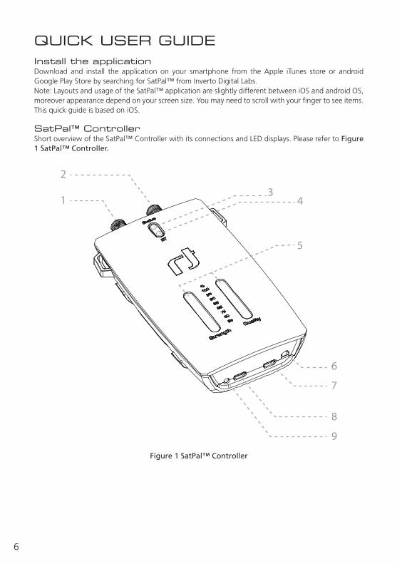
SatPal™ ControllerShort overview of the SatPal™ Controller with its connections and LED displays. Please refer to Figure 1 SatPal™ Controller.
Figure 1 SatPal™ Controller

7
En
En1. LNB/Switch (DC Out) – F-type
Connect to the LNB/ Multiswitch to be setup/programmed.
2. Receiver (DC IN, RF Loop) – F-typeRF signal loop-through and power supply (10-20V/13W max.) from receiver or power inserter.
3. Status LEDBlinking yellow: communication with LNB/Multiswitch.Steady green: configuration of connected dCSS device is same as configuration stored in SatPalTM Controller (standalone mode).
4. Bluetooth connection status LED:Blinking blue: not connected.Steady blue: connected.
5. Signal Strength and Quality LED barsIndicate signal strength and quality in standalone modesee, see Figure 2 Signal Strength:
Figure 2 Signal Strength
6. User ButtonUser button function can be setup in the SatPalTM application.
7. PC (Data only) – micro USBConnect to a PC to use SatPalTM Controller with PC application (power supply for the SatPalTM Controller only, not powering the connected LNB/Multiswitch).
8. DC in – micro USBPower supply (5-6V/13W max.) from battery pack or AC/DC adapter.
9. Power Status LEDred: Power supply not sufficient for connected device.yellow: Power supply sufficient to power connected device.
8
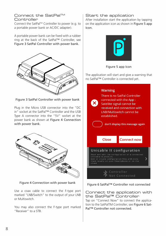
Connect the SatPalTM ControllerConnect the SatPalTM Controller to power (e.g. to a portable power bank or AC/DC adapter).
A portable power bank can be fixed with a rubber ring at the back of the SatPal™ Controller, see Figure 3 SatPal Controller with power bank.
Figure 3 SatPal Controller with power bank
Plug in the Micro USB connector into the “DC in” socket at the SatPal™ Controller and the USB Type A connector into the “5V” socket at the power bank as shown at Figure 4 Connection with power bank.
Figure 4 Connection with power bank
Use a coax cable to connect the F-type port marked “LNB/Switch” to the output of your LNB or Multiswitch.
You may also connect the F-type port marked “Receiver” to a STB.
Start the applicationAfter installation start the application by tapping on the application icon as shown in Figure 5 app Icon.
Figure 5 app Icon
The application will start and give a warning that no SatPal™ Controller is connected yet.
Figure 6 SatPal™ Controller not connected
Connect the application with the SatPal™ ControllerTap on “Connect Now” to connect the applica-tion to the SatPalTM Controller; see Figure 6 Sat-Pal™ Controller not connected.
9
En
!Attention! Connecting over Bluetooth is only possible via the application and not from the ge-neric iOS/Android Bluetooth settings.
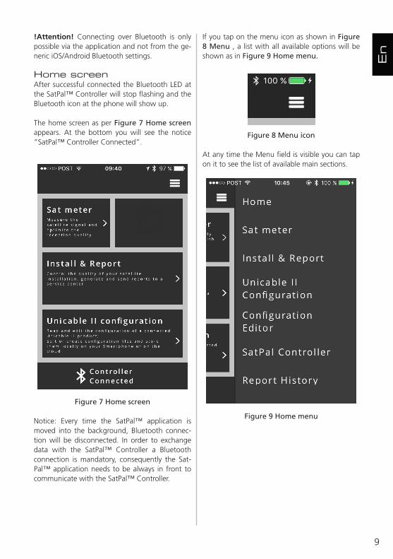
Home screenAfter successful connected the Bluetooth LED at the SatPal™ Controller will stop flashing and the Bluetooth icon at the phone will show up.
The home screen as per Figure 7 Home screen appears. At the bottom you will see the notice “SatPal™ Controller Connected”.
Figure 7 Home screen
Notice: Every time the SatPal™ application is moved into the background, Bluetooth connec-tion will be disconnected. In order to exchange data with the SatPal™ Controller a Bluetooth connection is mandatory, consequently the Sat-Pal™ application needs to be always in front to communicate with the SatPal™ Controller.
If you tap on the menu icon as shown in Figure 8 Menu , a list with all available options will be shown as in Figure 9 Home menu.
Figure 8 Menu icon
At any time the Menu field is visible you can tap on it to see the list of available main sections.
Figure 9 Home menu
10
Sat meterHome » Sat meter
The Sat meter function allows to measure satel-lite signals and to optimize the reception quality if needed. See Figure 10 Sat meter menu.
Figure 10 Sat meter menu
Use the wheel below section “Select satellite” to scroll and select the satellite you want to receive and below section “Select transponders (up to 4)” to select up to four transponders by scrolling the respective wheels.
Hint: If your satellite is not available on the list, you can select ‘Custom’ at the end of the list and then click on ‘Edit TP List’ at the bottom of the screen to freely customize its transponders’ pa-rameters.
Two signal bars, one for the signal strength and one for the signal quality, are displayed next to each of the four transponders.
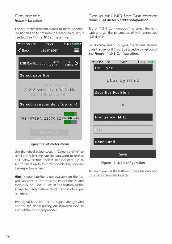
Setup of LNB for Sat meterHome » Sat meter » LNB Configuration
Tap on “LNB Configuration” to select the right type and set the parameters of your connected LNB device.
For Unicable and dCSS types, the desired Interme-diate Frequency (IF) must be typed in by keyboard. See Figure 11 LNB Configuration.
Figure 11 LNB Configuration
Tap on “Save” at the bottom to save the data and to go one screen backwards.

11
En
Sat meter signal metersHome » Sat meter » ‘signal bars’
Tapping on the “signal bars” at Figure 10 Sat meter menu will display detailed signal meters as seen on Figure 12 Signal meter.
At the top there is a sliding bar for all transpon-ders available over the selected satellite.
Home » Sat meter » ‘signal bars’ » ‘loud-speaker symbol’
Tap on “‘loudspeaker symbol’” to hear a sound, either for signal strength or MER (loudspeaker source is configurable under “Options”). Fre-quency or interval of sound will change according amplitude of chosen source and can be helpful when optimizing the dish alignment.
Figure 12 Signal meter
Sat meter OptionsHome » Sat meter » ‘signal bars’ » Options
Tap on “Options” as shown in Figure 12 Signal meter to change parameters for the Signal meters and buzzer. See Figure 13 Signal meter settings.
Figure 13 Signal meter settings
Signal Strength Smoothing: Use the “Slider” from 1 to 25 to set the level of responsiveness of the meter display for changes in signal strength per your preferences.
12
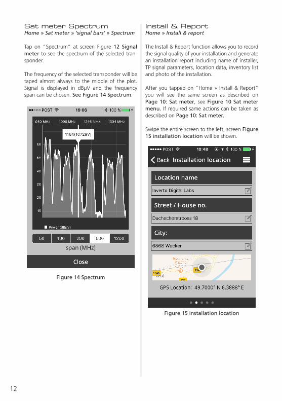
Sat meter SpectrumHome » Sat meter » ‘signal bars’ » Spectrum
Tap on “Spectrum” at screen Figure 12 Signal meter to see the spectrum of the selected tran-sponder.
The frequency of the selected transponder will be taped almost always to the middle of the plot. Signal is displayed in dBµV and the frequency span can be chosen. See Figure 14 Spectrum.
Figure 14 Spectrum
Install & ReportHome » Install & report
The Install & Report function allows you to record the signal quality of your installation and generate an installation report including name of installer, TP signal parameters, location data, inventory list and photo of the installation.
After you tapped on “Home » Install & Report” you will see the same screen as described on Page 10: Sat meter, see Figure 10 Sat meter menu. If required same actions can be taken as described on Page 10: Sat meter.
Swipe the entire screen to the left, screen Figure 15 installation location will be shown.
Figure 15 installation location

13
En
Tap on “+” to add a new equipment item. Figure 17 New equipment will appear.
Figure 17 New equipment
If the device has a barcode sticker you can tap on “scan” and use your smartphone camera to-wards the barcode to scan it. A successful scan will be noticed by a sound or vibration of the smartphone. Moreover you can see then the se-rial number at the field “Serial”, see Figure 19 After device scan.
!Attention! You have to allow the SatPal™ ap-plication to access the camera. Please refer to the related smartphone user manual for further instructions if the application has no access to the smartphone camera.
Type in your location data like “Location name”, “Street / House no.” and “City” to be shown in the site installation report.
Tap on the respective field to insert your data.
Swipe again the screen to the left and you will see the input screen for the “Equipment list” as shown in Figure 16 Equipment list.
Figure 16 Equipment list

14
If you have an Inverto LNB or Multiswitch device tap on “+” for Model. Screen Figure 18 New equipment Items# appears.
Figure 18 New equipment Items#
Enter Inverto’s 4 digit item number by scrolling the wheels accordingly. Afterwards the right de-scription and the respective model number will be displayed automatically.
Tap “Select” at the bottom to select the data and to go one screen backwards. See Figure 19 After device scan as example.
Figure 19 After device scan
!Attention! The “Description” field is mandato-ry. If not filled in automatically, information has to be typed in by keyboard.
15
En
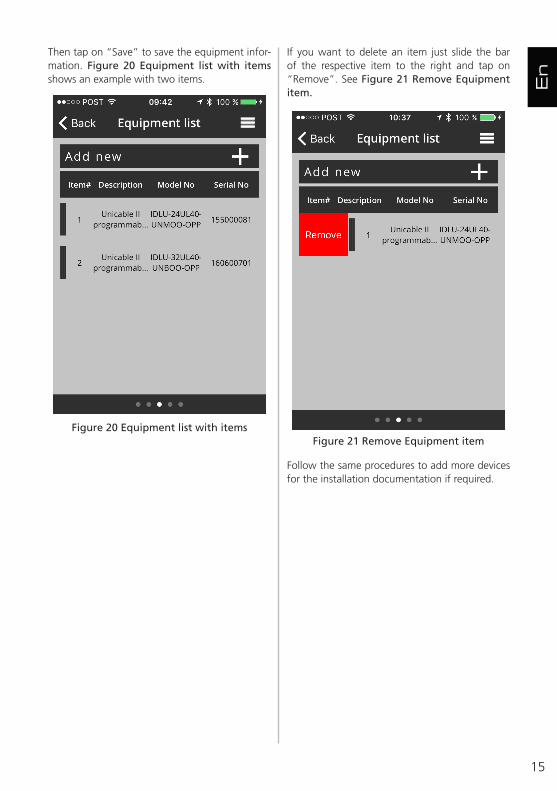
If you want to delete an item just slide the bar of the respective item to the right and tap on “Remove”. See Figure 21 Remove Equipment item.
Figure 21 Remove Equipment item
Follow the same procedures to add more devices for the installation documentation if required.
Then tap on “Save” to save the equipment infor-mation. Figure 20 Equipment list with items shows an example with two items.
Figure 20 Equipment list with items

16
Swipe again the screen to the left for the “Photo documentation” and take one or more pictures by tapping on “Take Photo”, see Figure 22 Photo documentation.
Figure 22 Photo documentation
Pictures can be deleted or re-taken at this section if needed.
Swipe again the screen to the left, see Figure 23 Installation summary.
Figure 23 Installation summary
You can check again the “Signal Quality” of max. 4 TP’s and you will see the location data used for the report.

17
En
Tap on “Send” to send the report. Screen as shown in Figure 24 Send Installation Report will be shown.
Figure 24 Send Installation Report
The report will be sent to the email address set at ‘target e-mail’ under the section Settings (“Home » Settings”, or described on Page 30: Settings).
18
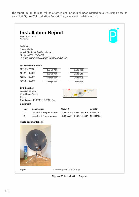
The report, in PDF format, will be attached and includes all prior inserted data. As example see an excerpt at Figure 25 Installation Report of a generated installation report.
Installation ReportSent: 2017-04-18At: 10:14
InstallerName: Martine-mail: [email protected]: 00352123456789ID: 758C5840-CD17-4A43-9E38-B7808E4DC24F
TP Signal Parameters
10719 V 27500 Strength 79% Quality 76%
10727 H 30000 Strength 79% Quality 51%
12245 H 29900 Strength 83% Quality 72%
12054 H 29900 Strength 65% Quality 78%
GPS LocationLocation name: aStreet house/no.: bCity: cCoordinates: 49.6999° N 6.3889° En
Equipment
No. Description Model # Serial #1 Unicable II programmabble IDLU-24UL40-UNMOO-OPP 1550000812 Unicable II Programmable IDLU-UWT110-CUO1O-32P 164001195
Photo documentation:
This report was generated by the SatPal app Page 1/1
Figure 25 Installation Report

19
En
Report HistoryHome » Report History
At this section you will find a list of sent reports stamped with date, time and location. See Figure 26 Report History.
Figure 26 Report History
By tapping on “Purge History” at the bottom you can purge all sent reports. A window to confirm will pop up prior deletion.
Tapping on a particular record on the list will dis-play the respective report. See Figure 27 Sent report as example.
Figure 27 Sent report
20
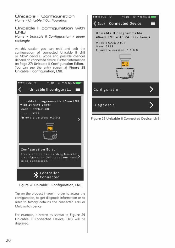
Unicable II ConfigurationHome » Unicable II Configuration
Unicable II configuration with LNBHome » Unicable II Configuration » upper rectangle
At this section you can read and edit the configuration of connected Unicable II LNB or MSW devices. Scope and possible changes depend on connected device. Further information on Page 27: Unicable II Configuration Editor.You can see the entry screen at Figure 28 Unicable II Configuration, LNB.
Figure 28 Unicable II Configuration, LNB
Tap on the product image in order to access the configuration, to get diagnosis information or to reset to factory defaults the connected LNB or Multiswitch device.
For example, a screen as shown in Figure 29 Unicable II Connected Device, LNB will be displayed.
Figure 29 Unicable II Connected Device, LNB

21
En
Tap on “Mode” to change the operating mode of the LNB. For an Unicable II LNB either “Dynamic” or “Static” mode. See Figure 31 Mode LNB.
Figure 31 Mode LNB
Tap on the desired “Mode” and then tap on “Save Changes” to save changes.
Tap on “Configuration” to read the configuration of the connected device.
The configuration data will be displayed on the screen as at Figure 30 Configuration, LNB.
Figure 30 Configuration, LNB
You can see the operating mode of the device and further down a list of configured UB’s with assigned Unicable protocol type(s), UB frequency and bandwidth.

22
Tap on a particular UB row below the section “Output” to change the particular UB configura-tion. See Figure 32 Configuration User Band, LNB.
Figure 32 Configuration User Band, LNB
At this section you can change via scrolling wheels the protocols supported by the UB (Unica-ble I (EN50494), Unicable II (EN50607) or both) as well as its frequency and bandwidth.
By tapping “Save” at the bottom the changes will be saved.
To disable a user band swipe the row of the re-quired UB to the right and tap on “Disable”, see Figure 33 Disable, Enable UB.
Figure 33 Disable, Enable UB
To enable a user band again do it vice versa by tapping on “Enable”.Afterwards tap on “Save Changes” to save changes.

23
En
A screen as shown at Figure 35 Unicable II Con-nected Device, MSW will be displayed.
Figure 35 Unicable II Connected Device,MSW
Tap on “Configuration” in order to read the con-figuration from the connected Multiswitch device.
Unicable II Configuration with MultiswitchHome » Unicable II Configuration
When an Unicable II Multiswitch is connected to the SatPal™ Controller, the screen at Figure 34 Unicable II Configuration, MSW will be displayed.
Figure 34 Unicable II Configuration, MSW
Tap on the product image in order to access the configuration or diagnosis information of the connected Multiswitch device.

24
When reading the configuration data is com-pleted, a screen as at Figure 36 Configuration, MSW will be displayed.
Figure 36 Configuration, MSW
On this screen, you can set the type of LNB that is connected to the Multiswitch (e.g. Quattro, Wideband), the functionality of the output ports (options depend on the specific Multiswitch mod-el, e.g. dual independent Unicable, dual shared Unicable, Unicable + Legacy) and the operating mode of the Multiswitch (static or dynamic). You can see the configured mode of the device and further down a list of configured UB’s with as-signed Unicable protocol type(s), occupied IF of mapped UB and bandwidth.
Tap on a particular UB row in order to edit the set-tings of that UB. See Figure 37 Configuration User Band, MSW.
Figure 37 Configuration User Band, MSW
By tapping “Save” at the bottom the changes will be saved.

25
En
Unicable II Configuration DiagnosticHome » Unicable II Configuration » ‘upper rectangle’ » Diagnostic
After tapping on “Unicable II Configuration” fol-lowed by tapping on the “upper rectangle” of connected device tap on “Diagnostic”.
At this section you have diagnostic tools available to see the occupied spectrum and to get detailed graphical information about temperature, re-sets and occupied UB’s of connected device. See Figure 39 Diagnostic for the Diagnostic entry screen.
Figure 39 Diagnostic
To disable a user band swipe the row of the re-quired UB to the right and tap on “Disable”, see Figure 38 Disable, Enable UB, MSW.
Figure 38 Disable, Enable UB, MSW
To enable a user band again do it vice versa by tapping on “Enable”.
Afterwards tap on “Save Changes” to save changes.

26
Unicable II Configuration Diagnostic SpectrumHome » Unicable II Configuration » ‘upper rectangle’ » Diagnostic » Spectrum
Tap on “Spectrum” to display in real time the spectrum at the input of the connected LNB or Multiswitch Figure 40 Spectrum diagnosis.
Figure 40 Spectrum diagnosis
To change the capture parameters tap on “Change” at Spectrum display. You will see changeable parameters as shown at Figure 41 Spectrum Capture Parameter.
Figure 41 Spectrum Capture Parameter
Tap on “Apply” to apply settings.
27
En
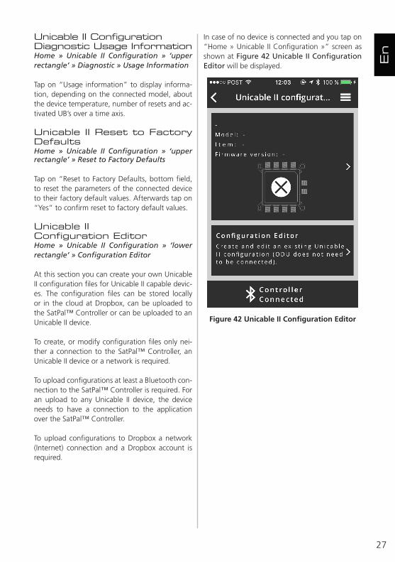
In case of no device is connected and you tap on “Home » Unicable II Configuration »” screen as shown at Figure 42 Unicable II Configuration Editor will be displayed.
Figure 42 Unicable II Configuration Editor
Unicable II Configuration Diagnostic Usage InformationHome » Unicable II Configuration » ‘upper rectangle’ » Diagnostic » Usage Information
Tap on “Usage information” to display informa-tion, depending on the connected model, about the device temperature, number of resets and ac-tivated UB’s over a time axis.
Unicable II Reset to Factory DefaultsHome » Unicable II Configuration » ‘upper rectangle’ » Reset to Factory Defaults
Tap on “Reset to Factory Defaults, bottom field, to reset the parameters of the connected device to their factory default values. Afterwards tap on “Yes” to confirm reset to factory default values.
Unicable II Configuration EditorHome » Unicable II Configuration » ‘lower rectangle’ » Configuration Editor
At this section you can create your own Unicable II configuration files for Unicable II capable devic-es. The configuration files can be stored locally or in the cloud at Dropbox, can be uploaded to the SatPal™ Controller or can be uploaded to an Unicable II device.
To create, or modify configuration files only nei-ther a connection to the SatPal™ Controller, an Unicable II device or a network is required.
To upload configurations at least a Bluetooth con-nection to the SatPal™ Controller is required. For an upload to any Unicable II device, the device needs to have a connection to the application over the SatPal™ Controller.
To upload configurations to Dropbox a network (Internet) connection and a Dropbox account is required.

28
Tap on “Home » Unicable II Configuration » Con-figuration Editor ‘lower rectangle’’” to come to the section “Local File System” as shown at Figure 43 Local File System. As example two configuration files are stored locally.
Figure 43 Local File System
To create a new configuration file tap on “+” and screen as displayed at Figure 44 New Configu-ration will appear.
Figure 44 New Configuration
At this screen you can chose the Unicable II de-vice for which a configuration should be gener-ated and later maybe modified. Scroll the wheel under “Device:” until the desired 4 digit inverto item number is displayed.
Under field “File Name:” type in a filename. As hint: A filename should always include Inverto’s 4 digit item number a date, and or a brief hint about the configuration or location.
By choosing the item number the application will generate a standard configuration with factory default settings and will store it with the given filename.
For instant, a configuration file for the LNB with the item number 5228 will be in dynamic mode with 24 UB’s. The first eight UB’s with the proto-col type I+II, UB’s 9 until 24 with protocol type II.
29
En
To upload the configuration file to the device (ODU) tap on “Upload to ODU”.
To upload the configuration file to the SatPal™ Controller tap on “Upload to SatPal Controller”.
To copy the configuration file to a prior linked Dropbox account tap on “Copy to Dropbox” (to link a Dropbox account refer to section “Home » Settings”).
If a Dropbox account has been linked you can see also a section for files stored at the Dropbox ac-count.
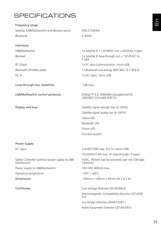
If you swipe a filename of the Dropbox account to the right you can tap on “Delete” to delete the file at the Dropbox account or you can tap on “Copy to Local File System” to copy the file to the local file system. See Figure 46 With Dropbox account linked.
Figure 46 With Dropbox account linked
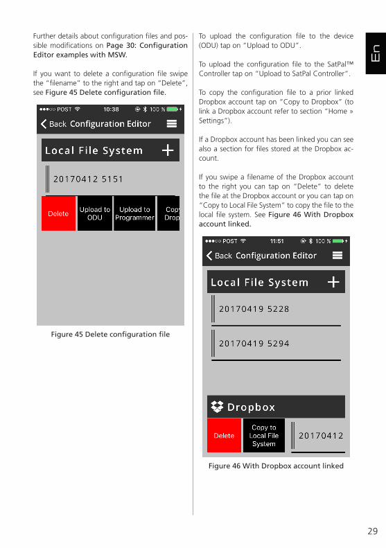
Further details about configuration files and pos-sible modifications on Page 30: Configuration Editor examples with MSW.
If you want to delete a configuration file swipe the “filename” to the right and tap on “Delete”, see Figure 45 Delete configuration file.
Figure 45 Delete configuration file

30
Configuration Editor examples with MSWDepending on the type of connected MSW de-vice, the configuration options will be displayed. !Attention! Creating/editing a product configu-ration requires a proper planning in advance to avoid a parameter overlapping which might cause misbehavior or loss of signals of the entire system and for the connected consumer devices.
!Attention! Each time you tap on “Save Chang-es” changed parameters will be stored to the file
finally. An undo is not possible.
SettingsHome » Settings
At this section you can see connected SatPal™ Controller, enter personal details of the installer, set the e-mail address where to send the instal-lation reports to, to link with a Dropbox account.
Tap “Home” to see the “Settings” menu item. See Figure 47 Home menu items.
Figure 47 Home menu items

31
En
SatPal™ ControllerHome » SatPal Controller
At this section you can trigger a firmware upgrade of the SatPal™ Controller, to set a TP Configura-tion for standalone mode, to define the function of the “User button” at the SatPal™ Controller and to reset the SatPal™ Controller to factory de-faults, see Figure 49 SatPal™ Controller Menu.
Figure 49 SatPal™ Controller Menu
Tap on “Settings” to enter the setting section. See Figure 48 Setting section.
Figure 48 Setting section
At each section you can tap on each header to insert the required data accordingly. For instant, tap on “Target e-mail” below the section “Re-porting” to enter the target e-mail where to send the reports to.

32
Firmware upgradeHome » SatPal Controller » Firmware upgrade
Tap on “Firmware upgrade” at “Home » Control-ler” to change to the firmware upgrade section.
To start the firmware upgrade tap on “Start”.The firmware upgrade will start. While the firm-ware is being uploaded you can see a progress bar starting from 1 until 1000. After successful upload the SatPal™ Controller will restart.
After successful upload the SatPal™ Controller will restart. Afterwards a pop up window will in-form about the finished update, just tap on “OK” to confirm.
Firmware upgrades are provided over the Sat-Pal™ application.
TP ConfigurationHome » SatPal Controller » TP Configuration
At this section you can configure four TP’s for the toggling mode while the SatPal™ Controller is used in standalone mode as described on Page 35: User Button Function.
Each of the four configurable TP’s can be either assigned to one LNB (dCSS capable or Universal LNB) or can be assigned to four different LNB’s.
!Attention! Any configuration of these data re-quires a proper planning in advance to avoid a parameter overlapping which might cause misbe-havior or loss of signals of the entire system and for the connected consumer devices in case of.
Tap on “TP Configuration” at “Home » SatPal Controller” and a configuration screen as shown at Figure 50 TP Configuration will be displayed.
Figure 50 TP Configuration

33
En
For instance, to setup a configuration for TP1, tap on the “row of TP1”. A screen as shown at Figure 51 TP Configuration TP1 will be dis-played.
Figure 51 TP Configuration TP1
Tap on “LNB Configuration” to configure the LNB type and LNB related parameters. Almost all pa-rameters can be chosen per scrolling wheel in this section.
LNB Type:You can choose between dCSS Dynamic or Universal. If you choose Universal you can assign the satellite position, e.g. “A”.
If you choose dCSS Dynamic you can assign the satellite position, UB frequency (by typing in the frequency value), UB number (1 to max. 32) and the Unicable protocol type (I or II).
See Figure 52 TP Configuration LNB Type as example for dCSS LNB setup.
Figure 52 TP Configuration LNB Type
Tap on “Save” at the bottom to save the config-uration and to go back to Figure 51 TP Config-uration TP1 to set up desired satellite and tran-sponder for TP1.
At the middle of the screen below the section “Se-lect Satellite” you have a scrolling wheel whereby you can choose desired satellite. After the satellite is chosen you can choose below the section “Se-lect transponder” the desired transponder.
Hint: Satellite data and related transponder data are provided by the SatPal™ application.

34
Tap on “Select” to apply your selection.
After all TP’s have been assigned and configured accordingly you have to tap on “Send to SatPal Controller” at Figure 50 TP Configuration to send the configuration to the SatPal™ Controller and to be able to toggle twhe TP’s as described on Page 34: User Button Function.
User Button FunctionHome » SatPal Controller » User Button Func-tion
The SatPal™ Controller has a small button, right beside the Micro USB socket for “PC (Data Only)”. This button can be programmed to use it either for sending a prior uploaded configuration to an ODU device or to toggle between four TP’s when using the SatPal™ Controller in a stand-alone mode (i.e. not through the application). See Figure 53 User Button Function.
Setup of TP’s to be toggled are described on Page 32: TP Configuration.
Figure 53 User Button Function
Chose with the scrolling wheel either “TP Tog-
gle” or “Send Config” and then tap on “Send to SatPal Controller” at the bottom to upload the setting to the SatPal™ Controller.
A window to confirm the upload will pop up. Tap on “Close” to close that window.
While toggling the TP’s as configured on Page 32: TP Configuration.And without a smartphone connected you can see signal strength and signal quality at the front panel SatPal™ Controller, see Figure 1 SatPal™ Controller, item 5.
Reset to Factory DefaultsHome » SatPal Controller » Reset to Factory Defaults
In some cases it might be required to reset the SatPal™ Controller to the factory default settings.
Tap on “Reset to Factory Defaults” at “Home » SatPal Controller”. A window with a warning will pop up. To trigger the “reset to factory defaults” tap on “Yes”. See Figure 54 Reset to Factory Defaults .
Figure 54 Reset to Factory Defaults
35
En
En
SPECIFICATIONSFrequency range
Satellite (LNB/Multiswitch and Receiver ports) 950-2150MHz
Bluetooth 2.4GHz
Interfaces
LNB/Multiswitch 1x Satellite IF + 13/18VDC out + 0/22kHz, F-type
Receiver 1x Satellite IF loop-through out + 13/18VDC in, F-type
PC (Data) 1x PC data communication, micro USB
Bleutooth (Wireless data) 1x Bluetooth low energy (IEEE 802.15.1 BT4.0)
DC In 1x DC input, micro USB
Loop-through loss (Satellite) 1dB max.
LNB/Multiswitch control protocols DiSEqC™ 2.0, EN50494 (Unicable/SatCR) ,EN50607 (Unicable II/dCSS)
Display and keys Satellite signal strength bar (0-100%)
Satellite signal quality bar (0-100%)
Status LED
Bluetooth LED
Power LED
Function button
Power Supply
DC input 5-6VDC/13W max. (DC In, micro USB)
10-20VDC/13W max. (IF loop-through, F-type))
SatPal Controller (without power supply to LNB/Multiswitch)
5VDC, 350mA (can be powered over the USB data interface)
Power supply to LNB/Multiswitch 14V-18V, 400mA max.
Operating temperature -10°C ~ 40°C
Dimensions 150mm x 100mm x 30mm (W x D x H)
Certificates Low Voltage Directive (2014/35/EU)
Electromagnetic Compatibility Directive (2014/30/EU)
Eco-Design Directive (2009/125/EC)
Radio Equipment Directive (2014/53/EU)

36
ABBREVIATIONS BER Bit Error RateC/N Carrier to Noise ratiodCSS Digital Channel Stacking SystemIF Intermediate FrequencyLNB Low Noise Block ConverterMER Modulation Error RatioMSW MultiswitchODU Outdoor Unit: e.g. LNB, MultiswitchSTB Set-Top-BoxTP TransponderUB User Band

37
En
En

38
For purpose of brevity, some product descriptions in this sheet remain at platform level and may not be referred to as detailed datasheets of the products. Inverto Digital Labs reserves the right to amend, omit or add products, product-lines, and / or fea-tures without notice. As product specifications may change without notice, always contact Inverto to obtain the latest product specification sheets.
For further details contact: [email protected]
FTA Communication Technologies S.à.r.l Tel. +352 264 367 1 Fax. +352 264 313 68
V090517