sauter modulo system description · sauter modulo system description system overview d100402674...
TRANSCRIPT
SAUTER modulo system description
Overview of the SAUTER modulo product line
Document number D100374772

SAUTER modulo system description
Introduction
D100402674
2/98
SAUTER modulo system description
Introduction
D100402674
3/98
Contents
Contents ........................................................................................................................................... 3
1 Introduction ............................................................................................................................... 7
2 System overview ....................................................................................................................... 9
2.1 Topology ...................................................................................................................... 10
2.2 Description ................................................................................................................... 11
3 Building automation ............................................................................................................... 15
3.1 modulo 6 Automation Stations ..................................................................................... 17
3.1.1 Overview ...................................................................................................................... 17
3.1.2 modu680-AS modular BACnet automation station and web server (EY6AS80F021) 19
Technical data .......................................................................................................................... 19
Description ............................................................................................................................... 20
3.1.3 modu660-AS modular BACnet automation station (EY6AS60F011) .......................... 22
Technical data .......................................................................................................................... 22
Description ............................................................................................................................... 23
3.2 modulo 6 Integration Solutions .................................................................................... 25
3.2.1 Overview ...................................................................................................................... 25
3.2.2 modu612-LC IP Coupler for IO-Modules with Webserver (EY6LC12F011) ................ 27
Technical data .......................................................................................................................... 27
Description ............................................................................................................................... 28
3.2.3 modu601-LC module for separated I/O module supply (EY6LC01F001) ................... 29
Technical data .......................................................................................................................... 29
Description ............................................................................................................................... 29
3.2.4 modu602-LC coupling kit I/O modules in cabinet (EY6LC02F001) ............................. 30
Technical data .......................................................................................................................... 30
Description ............................................................................................................................... 30
3.3 modulo 6 I/O Modules .................................................................................................. 31
3.3.1 Overview ...................................................................................................................... 31
3.3.2 modu630-IO 16 x DI/CI inputs I/O module (EY6IO30F001) ........................................ 35
Technical data .......................................................................................................................... 35
Description ............................................................................................................................... 35
3.3.3 modu631-IO 8 x UI(DI/CI/AI) + 8 x DI/CI I/O module (EY6IO31F001) ........................ 36
Technical data .......................................................................................................................... 36
Description ............................................................................................................................... 36
3.3.4 modu650-IO 6 x relay (2A) outputs I/O module (EY6IO50F001)................................. 37
Technical data .......................................................................................................................... 37
Description ............................................................................................................................... 37
3.3.5 modu670-IO 8 x DI/CI/DO(OC) + 8 x DI/CI I/O module (EY6IO70F001)..................... 38
Technical data .......................................................................................................................... 38
SAUTER modulo system description
Introduction
D100402674
4/98
Description ............................................................................................................................... 38
3.3.6 modu671-IO 8 x AO + 8 x DI/CI IO-Module (EY6IO71F001) ...................................... 39
Technical data .......................................................................................................................... 39
Description ............................................................................................................................... 39
3.3.7 modu672-IO 4 x UO(DO/AO) + 4 x UI(DI/CI/AI) IO-Module (EY6IO72F001).............. 40
Technical data .......................................................................................................................... 40
Description ............................................................................................................................... 40
3.3.8 modu600-LO, operating and indicating unit for I/O modules (EY6LO00F001) ........... 42
Technical data .......................................................................................................................... 42
Description ............................................................................................................................... 42
3.4 modulo 6 Communication Modules ............................................................................. 44
3.4.1 Overview ...................................................................................................................... 44
3.4.2 modu620-CM Modbus-RTU (RS-485) Communication Module (EY6CM20F011) ...... 46
Technical data .......................................................................................................................... 46
Description ............................................................................................................................... 46
3.4.3 modu630-CM SLC-(EY6CM30F031) communication module (EY6CM30F031) ........ 48
Technical data .......................................................................................................................... 48
Description ............................................................................................................................... 48
3.4.4 modu640-CM KNX-TP communication module (EY6CM40F041) .............................. 49
Technical data .......................................................................................................................... 49
Description ............................................................................................................................... 49
3.4.5 modu660-CM SLC-communication module (EY6CM60F061) .................................... 51
Technical data .......................................................................................................................... 51
Description ............................................................................................................................... 51
3.4.6 modu650-CM SLC-communication module (EY6CM50F051) .................................... 53
Technical data .......................................................................................................................... 53
Description ............................................................................................................................... 53
3.5 modulo 6 Web Operation and Services ....................................................................... 55
3.5.1 moduWeb Unity ........................................................................................................... 55
Overview .................................................................................................................................. 55
System management ............................................................................................................... 56
moduWeb Unity Visualisation .................................................................................................. 57
moduWeb Unity Network ......................................................................................................... 58
4 Room automation ................................................................................................................... 59
4.1 ecos 5 room automation .............................................................................................. 59
4.1.1 ecos500, ecos502, ecos504/505 Room Automation Station ...................................... 59
4.1.2 ecoUnit room operating units ....................................................................................... 63
4.1.3 ecoUnit-Touch room operating units ........................................................................... 66
4.1.4 Remote ecoLink I/O modules ...................................................................................... 67
5 Building Management and Control ....................................................................................... 70
5.1 SAUTER Vision Center – central building management and visualisation ................. 70
SAUTER modulo system description
Introduction
D100402674
5/98
5.2 SAUTER Engineering Suite ......................................................................................... 72
6 System integration ................................................................................................................. 73
6.1 Overview ...................................................................................................................... 74
6.2 modulo 5 ...................................................................................................................... 74
6.3 Legacy (novaNet) ........................................................................................................ 75
6.4 Fieldbus, SLC .............................................................................................................. 75
6.5 Industrial ...................................................................................................................... 75
6.6 SAUTER Vision Center allows the integration of third-party systems with the OPC UA
industrial protocol IoT and the Cloud ........................................................................... 75
6.7 Network services ......................................................................................................... 75
7 Integrated CASE Suite service .............................................................................................. 77
7.1 CASE Builder ............................................................................................................... 78
7.2 CASE Engine ............................................................................................................... 78
7.3 CASE Vision ................................................................................................................ 79
7.4 CASE Library Management ......................................................................................... 79
7.5 Components ................................................................................................................ 79
7.5.1 CASE VAV ................................................................................................................... 79
7.5.2 CASE VAV Factory ...................................................................................................... 80
7.5.3 CASE TPC (Touch Panel Configurator) ...................................................................... 80
7.5.4 CASE Drives ................................................................................................................ 80
7.5.5 CASE Sensors ............................................................................................................. 80
7.6 CASE Tools ................................................................................................................. 80
7.6.1 CASE Export ................................................................................................................ 80
7.6.2 CASE Export BACnet .................................................................................................. 81
7.6.3 CASE Export novaNet ................................................................................................. 81
7.6.4 CASE Import ................................................................................................................ 81
7.6.5 BACnet Server Configurator ........................................................................................ 81
7.7 Communication ............................................................................................................ 81
7.7.1 CASE HWC (hardware commissioning) ...................................................................... 81
7.7.2 CASE Sun .................................................................................................................... 81
7.7.3 novaMit29x .................................................................................................................. 82
7.7.4 Virtual Port Configurator .............................................................................................. 82
8 Further information ................................................................................................................ 83
8.1 BACnet Communication Protocol ................................................................................ 83
8.1.1 BACnet......................................................................................................................... 83
8.1.2 Native BACnet ............................................................................................................. 84
8.1.3 BACnet/IP .................................................................................................................... 84
8.1.4 BACnet/MSTP ............................................................................................................. 85
8.1.5 BACnet/SC .................................................................................................................. 86
8.2 MQTT Communication Protocol .................................................................................. 89

SAUTER modulo system description
Introduction
D100402674
6/98
Glossary ......................................................................................................................................... 92
List of figures ................................................................................................................................. 95
List of tables .................................................................................................................................. 96
SAUTER modulo system description
Introduction
D100402674
7/98
1 Introduction
EY-modulo 6 is the high-end building management system from SAUTER. With new
automation stations and a new system topology, modulo 6 offers extended flexibility and
scalability. The SAUTER modulo system family covers all applications in regulation and
control technology from HVAC, building and energy management to flexible solutions in
integrated room automation. Welcome to the age of BIoT, Building IoT.
modulo 6 moves the digital transformation of building automation one step further.
While the previous generation already provided innovative Internet-based functions such
as BACnet/IP, email notifications and embedded web servers, modulo 6 extends
modularity and interoperability via the Internet and the cloud by permitting the relocation
of I/O and COM modules via the network. The standard communication of modulo 6 is
based on the standard BACnet/IP protocol. Special functions such as email notifications,
text messages and network synchronisation as well as the web server and RESTful API
are based fully on IP communication.
Digitalisation, and in particular the Internet of Things (IoT), open new applications in the
areas of data processing in the cloud, operation via end devices such as smartphones
and tablets, integration of communicative, smart sensors and networking with cloud
services such as data analytics or voice services such as Amazon Alexa and Google
Home. However, they also involve new threats. For this reason, security was a main
focus when developing modulo 6. The security by design policy, following the
IEC 62443 standard, is a key attribute of the modulo 6 development, resulting in a set of
hardware and software features, all oriented to make the use of modulo 6 as safe as
possible.
Tooling is also a critical aspect of the realisation of building automation solutions.
Productivity is a key factor for efficient, error-free project processing. The new version
(4) of CASE is also downwards-compatible and enables the migration of existing
modulo 5 projects to modulo 6.
SAUTER Vision Center (SVC) is the powerful solution for building and energy
management. SVC also offers important functions for maintenance management and
data analysis. SAUTER Vision Services provide these functions in the cloud.
The SAUTER Cloud Solutions will provide new ways of working and interacting with the
building environment. New solutions are provided “as a Service”, both for technicians
and for end users. The SAUTER Portal offers access to immediately usable functions
and libraries and enables all devices to be managed via the cloud. Mobile Building
Solutions ensures the operation of the heating and climate functions, including lighting
and sunshading in rooms and apartments, via smartphone and tablet.
Exciting new possibilities are in reach with modulo 6.

SAUTER modulo system description
Introduction
D100402674
8/98
SAUTER modulo system description
System overview
D100402674
9/98
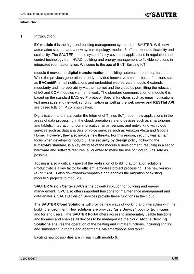
2 System overview
SAUTER modulo system description
System overview
D100402674
10/98
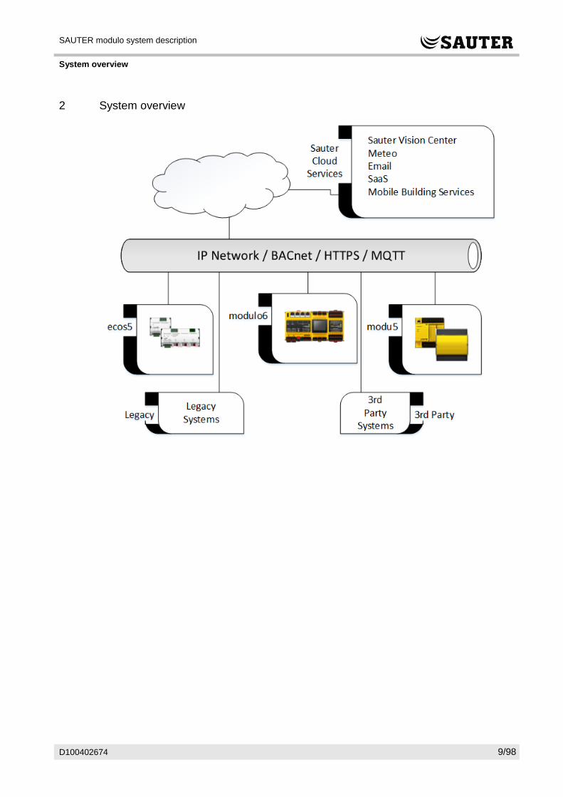
2.1 Topology
SAUTER modulo system description
System overview
D100402674
11/98
2.2 Description
modulo 6 provides the solutions to respond to these needs in the age of the Internet of
Things and the 4.0 industrial revolution. The new controllers provide enhanced
automation power. Furthermore, the connectivity between modulo 6 and modulo 5 is
secured by BACnet/IP interoperability.
modulo 6 in the era of digitalisation
modulo 6 Automation Stations are the foundation of the complete modulo 6 system
family for interconnected regulation, control and monitoring of building automation
systems (BAS).
The system includes the following product lines:
Sauter modulo 6 product line of modular Automation Stations and modules
Sauter Vision Center building and energy management control system
SAUTER CASE Suite engineering software
SAUTER solution libraries
Intelligent actuators
Intelligent sensors and terminals
SAUTER Cloud solutions
SAUTER modulo system description
System overview
D100402674
12/98
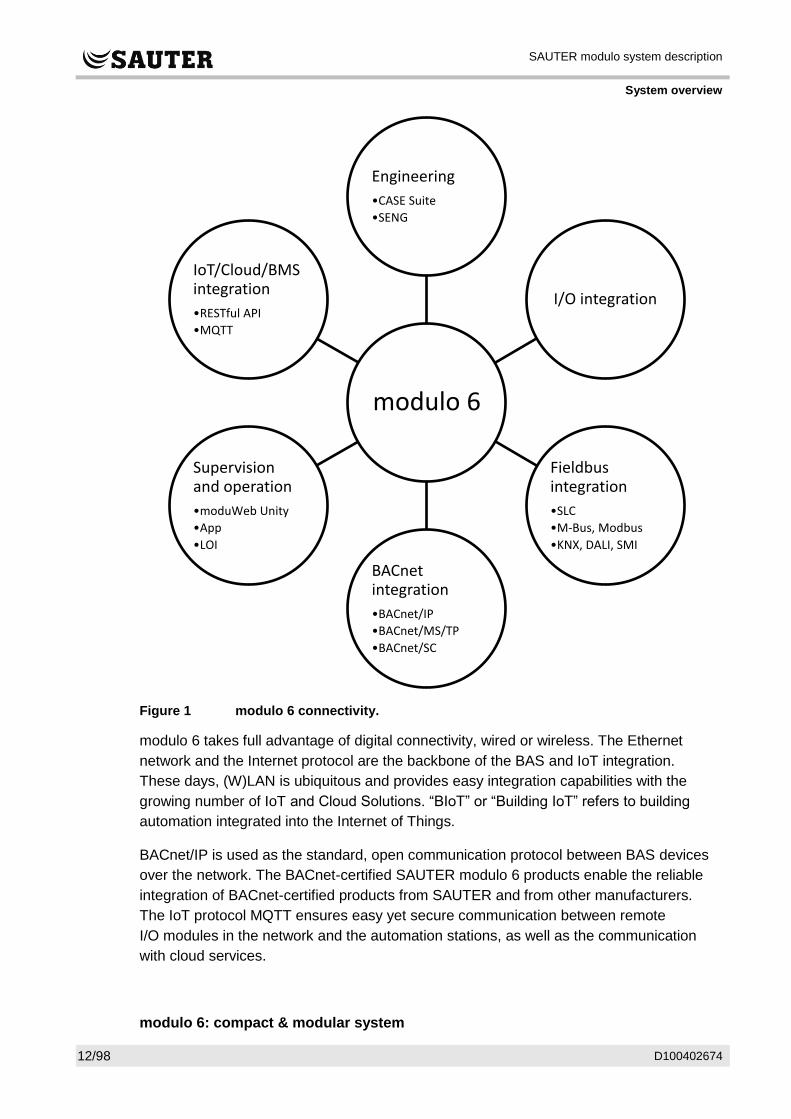
Figure 1 modulo 6 connectivity.
modulo 6 takes full advantage of digital connectivity, wired or wireless. The Ethernet
network and the Internet protocol are the backbone of the BAS and IoT integration.
These days, (W)LAN is ubiquitous and provides easy integration capabilities with the
growing number of IoT and Cloud Solutions. “BIoT” or “Building IoT” refers to building
automation integrated into the Internet of Things.
BACnet/IP is used as the standard, open communication protocol between BAS devices
over the network. The BACnet-certified SAUTER modulo 6 products enable the reliable
integration of BACnet-certified products from SAUTER and from other manufacturers.
The IoT protocol MQTT ensures easy yet secure communication between remote
I/O modules in the network and the automation stations, as well as the communication
with cloud services.
modulo 6: compact & modular system
modulo 6
Engineering
•CASE Suite
•SENG
I/O integration
Fieldbus integration
•SLC
•M-Bus, Modbus
•KNX, DALI, SMI
BACnet integration
•BACnet/IP
•BACnet/MS/TP
•BACnet/SC
Supervision and operation
•moduWeb Unity
•App
•LOI
IoT/Cloud/BMS integration
•RESTful API
•MQTT
SAUTER modulo system description
System overview
D100402674
13/98
The modu680-AS station is the flagship of the modulo 6 Automation Stations. It is
intended for the regulation and control of both HVAC primary energy preparation
applications as well as IRC demand applications. Two different, separate networks
enable the clear separation of the exchange of operation data for the building automation
and the requirements of external systems, e.g. BMS or web clients. The large capacity
and the multi-process capability enable multiple applications to be implemented with a
single controller. Thanks to the modular structure and the flexibility of the fitting, any
topology is possible. Up to 24 modules can be directly attached. Up to 5 communication
modules for fieldbus integration can be directly attached. Integration of SAUTER devices
using the SAUTER Local Communication bus (SLC) and a Modbus RTU or
BACnet/MSTP is directly available on the station.
The modu660-AS station is the optimised station supporting the core functionality for
more decentralised topologies. Up to 24 modules can be attached to the station, and
also over the SLC Interface. The station remains tightly integrated over BACnet.
The modu612-LC provides additional topology flexibility to remotely communicate with
I/O modules over LAN as well as over the cloud. It also enables direct communication
with cloud services. The modu612-LC and the I/O modules attached to it are assigned to
an Automation Station as part of its dataset.
modulo 6 devices are built using an industrial grade, high performance CPU. They have
been designed for long-term availability and for applications in automation areas using
multiple communication protocols.
modulo 6 hardware reduces installation and commissioning overheads thanks to the:
Compact, standardised form factor (DIN 43880)
Frontal slide-in assembly with spring contacts
Protection cover for I/O bus termination
Pluggable, push-in spring connectors
modu602-LC line-break kit
modu601-LC power injection module
modu600-LO universal operation and indication unit
The modu600-LO Local Operation and Indication unit is a universal LOI that can be set
on any of the modu6** I/O modules. With its simplified user interface and a high-
resolution colour LCD screen, the unit enables the easily visualisation of the I/O module
and its signals , and allows to operate the signals directly. The same function can be
done with the mobile App1 via the Bluetooth interface or the commissioning web server.
moduWeb Unity and the Visualization of Things
moduWeb Unity is the embedded web server accessible with any HTML5 web browser.
It includes most of the functions of PC-based SCADA systems but is directly accessible
via the web server. The core functionality provides any user with an easy to use
graphical user interface for interacting with the system. Buildings and spaces within a
1 Sauter Commissioning modulo 6 App for iOS and Android. Available on AppleStore and GooglePlay.
SAUTER modulo system description
System overview
D100402674
14/98
building, such as complete floors or individual rooms, as well as technical installations,
can be graphically represented and operated intuitively. BACnet objects are mapped
structurally. Specialised views for schedules, calendars and Trend Logs make day-to-day
use of these functions a piece of cake. Alarms have their own dedicated view and can be
notified to registered users by e-mail or text messaging.
moduWeb Unity facilitates the commissioning of all IP-capable modulo 6 devices.
Setting up the station and make wiring tests is made easy, even before the final
application is loaded. Part of the commissioning includes the security settings such as
user creation and rights assignment for the station and web server, enabling of
communication interfaces and protocols, loading encryption certificates or application
backup and restoration.
modulo 6 and Cybersecurity
The Internet has opened up a new universe of possibilities but has also brought a new
range of threats with it. modulo 6 has been designed with this in mind from the very
beginning. IEC 62443 has been used as a guideline. Sensitive data is stored in
encrypted form, while the TLS technology is used for communication encryption.
Further features of modulo 6 also provide additional security. modu680-AS has an
integrated network separation for Internet and building automation. Interfaces that are
not being used can be deactivated by authorised users. Access control lists (black list,
white list) can also be set up to limit the communication between devices.

SAUTER modulo system description
Building automation
D100402674
15/98
3 Building automation
modulo 6 Automation Page 17
EY6AS80F021
modu680-AS
Modular BACnet
automation
station and web
server
EY6AS60F011
modu660-AS
modular BACnet
automation
station
modulo 6 Integration Solutions Page 25
EY6LC12F011
modu612-LC
IP coupler for
I/O modules with
web server
EY6LC01F001
modu601-LC
Module for
separate
I/O module
supply
EY5LC02F001
modu602-LC
Coupling kit for
I/O modules in
cabinet
modulo 6 I/O Modules Page 31
EY6IO30F001
modu630-IO
16 x DI/CI inputs
I/O module
EY6IO31F001
modu631-IO
8 x UI(DI/CI/AI)
and 8 x DI/CI
I/O module
EY6IO50F001
modu650-IO
6 x relay (2A)
outputs I/O
module
EY6IO70F001
modu670-IO
8 x DI/CI/DO
(OC) and
8 x DI/CI
I/O module
EY6IO71F001
modu671-IO
8 x AO and
8 x DI/CI I/O
module
EY6IO72F001
modu672-IO
4 x UO(DO/AO)
and
4 x UI(DI/CI/AI)
I/O module
EY6LO00F001
modu600-LO
Local operating
and indicating
unit for
I/O modules
SAUTER modulo system description
Building automation
D100402674
16/98
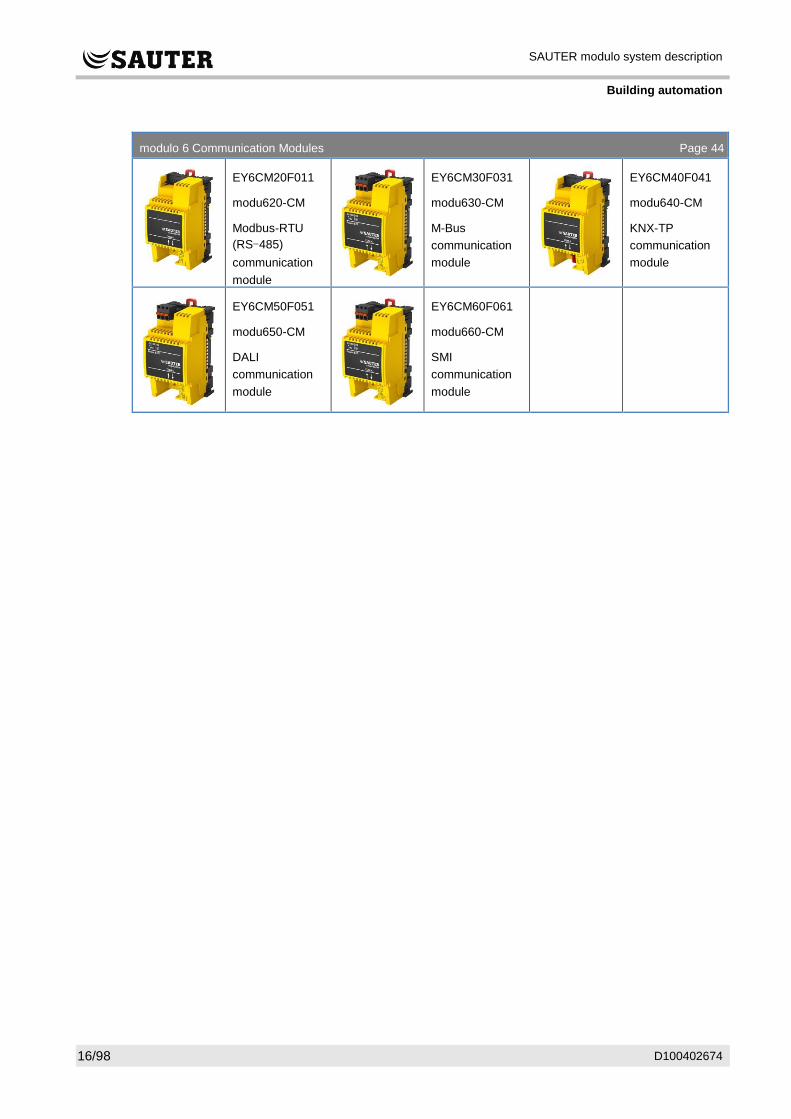
modulo 6 Communication Modules Page 44
EY6CM20F011
modu620-CM
Modbus-RTU
(RS-485)
communication
module
EY6CM30F031
modu630-CM
M-Bus
communication
module
EY6CM40F041
modu640-CM
KNX-TP
communication
module
EY6CM50F051
modu650-CM
DALI
communication
module
EY6CM60F061
modu660-CM
SMI
communication
module
SAUTER modulo system description
Building automation
D100402674
17/98
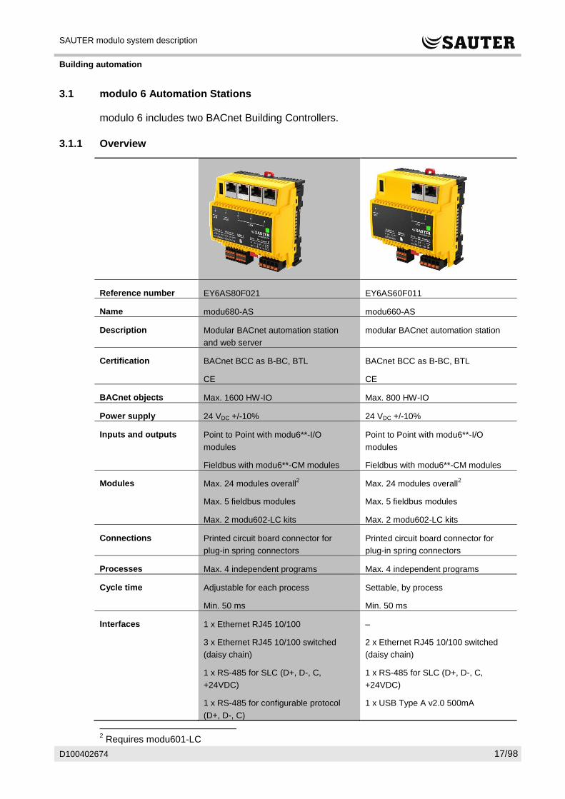
3.1 modulo 6 Automation Stations
modulo 6 includes two BACnet Building Controllers.
3.1.1 Overview
Reference number EY6AS80F021 EY6AS60F011
Name modu680-AS modu660-AS
Description Modular BACnet automation station
and web server
modular BACnet automation station
Certification BACnet BCC as B-BC, BTL
CE
BACnet BCC as B-BC, BTL
CE
BACnet objects Max. 1600 HW-IO Max. 800 HW-IO
Power supply 24 VDC +/-10% 24 VDC +/-10%
Inputs and outputs Point to Point with modu6**-I/O
modules
Fieldbus with modu6**-CM modules
Point to Point with modu6**-I/O
modules
Fieldbus with modu6**-CM modules
Modules Max. 24 modules overall2
Max. 5 fieldbus modules
Max. 2 modu602-LC kits
Max. 24 modules overall2
Max. 5 fieldbus modules
Max. 2 modu602-LC kits
Connections Printed circuit board connector for
plug-in spring connectors
Printed circuit board connector for
plug-in spring connectors
Processes Max. 4 independent programs Max. 4 independent programs
Cycle time Adjustable for each process
Min. 50 ms
Settable, by process
Min. 50 ms
Interfaces 1 x Ethernet RJ45 10/100
3 x Ethernet RJ45 10/100 switched
(daisy chain)
1 x RS-485 for SLC (D+, D-, C,
+24VDC)
1 x RS-485 for configurable protocol
(D+, D-, C)
–
2 x Ethernet RJ45 10/100 switched
(daisy chain)
1 x RS-485 for SLC (D+, D-, C,
+24VDC)
1 x USB Type A v2.0 500mA
2 Requires modu601-LC

SAUTER modulo system description
Building automation
D100402674
18/98
1 x USB Type A v2.0 500mA
1 x microSD
1 x Bluetooth
1 x microSD
1 x Bluetooth
Alive Signal 0, 1…5 Hz Max. 24 V 0, 1…5 Hz Max. 24 V
RTC Yes
CR2032 battery (exchangeable)
Yes
CR2032 battery (exchangeable)
Dimensions W (↔) 87.5 mm (5 TE)
L (↕) 100 mm
H (↨) 58.3 mm
W (↔) 87.5 mm (5 TE)
L (↕) 100 mm
H (↨) 58.3 mm
Important information
modu680-AS and modu660-AS can power-up up to 12 COM and I/O modules, including
the LOI on I/O modules. To power-up the maximum supported 24 modules, the
modu601-LC module is needed.
The SD-Card support includes hot plugging the SD-Card. The SD card can also be
changed during operation. The data is stored locally and then synchronised with the new
storage medium at a later time. The local storage capacity is limited to 64 MB which
under normal load can represent up to 3 days.
The battery is only for powering the internal clock. The battery is designed for a
serviceable life of up to 10 years but it can be replaced. This is done by removing the
cover and inserting a new battery. Be aware of the danger of explosion of the cell battery
during removal if short-circuited!
The SLC interface does not support older versions of ecoLink modules. Check
compatibility when upgrading older installations. Check the list of supported devices
below:
Device Critical characteristic Production
EY-EM510, EY-EM511, EY-EM512,
EY-EM520, EY-EM521, EY-EM526
Firmware V1.21 and newer Since June 2015
EY-EM522 Firmware V1.02 and newer Since September 2014
EY-EM514, EY-EM515, EY-EM523,
EY-EM527
Any
EY-EM580 Index G 2017 and newer
SAUTER modulo system description
Building automation
D100402674
19/98
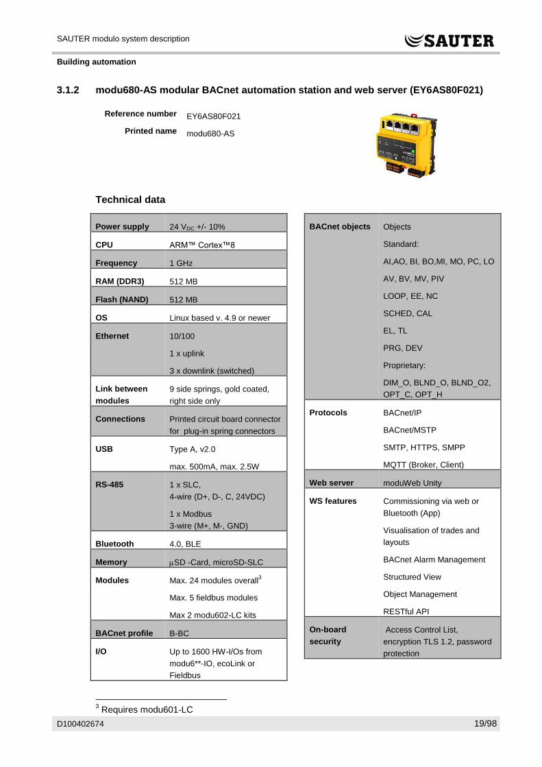
3.1.2 modu680-AS modular BACnet automation station and web server (EY6AS80F021)
Reference number EY6AS80F021
Printed name modu680-AS
Technical data
Power supply 24 VDC +/- 10%
CPU ARM™ Cortex™8
Frequency 1 GHz
RAM (DDR3) 512 MB
Flash (NAND) 512 MB
OS Linux based v. 4.9 or newer
Ethernet 10/100
1 x uplink
3 x downlink (switched)
Link between
modules
9 side springs, gold coated,
right side only
Connections Printed circuit board connector
for plug-in spring connectors
USB Type A, v2.0
max. 500mA, max. 2.5W
RS-485 1 x SLC,
4-wire (D+, D-, C, 24VDC)
1 x Modbus
3-wire (M+, M-, GND)
Bluetooth 4.0, BLE
Memory SD -Card, microSD-SLC
Modules Max. 24 modules overall3
Max. 5 fieldbus modules
Max 2 modu602-LC kits
BACnet profile B-BC
I/O Up to 1600 HW-I/Os from
modu6**-IO, ecoLink or
Fieldbus
3 Requires modu601-LC
BACnet objects Objects
Standard:
AI,AO, BI, BO,MI, MO, PC, LO
AV, BV, MV, PIV
LOOP, EE, NC
SCHED, CAL
EL, TL
PRG, DEV
Proprietary:
DIM_O, BLND_O, BLND_O2,
OPT_C, OPT_H
Protocols BACnet/IP
BACnet/MSTP
SMTP, HTTPS, SMPP
MQTT (Broker, Client)
Web server moduWeb Unity
WS features Commissioning via web or
Bluetooth (App)
Visualisation of trades and
layouts
BACnet Alarm Management
Structured View
Object Management
RESTful API
On-board
security
Access Control List,
encryption TLS 1.2, password
protection
SAUTER modulo system description
Building automation
D100402674
20/98
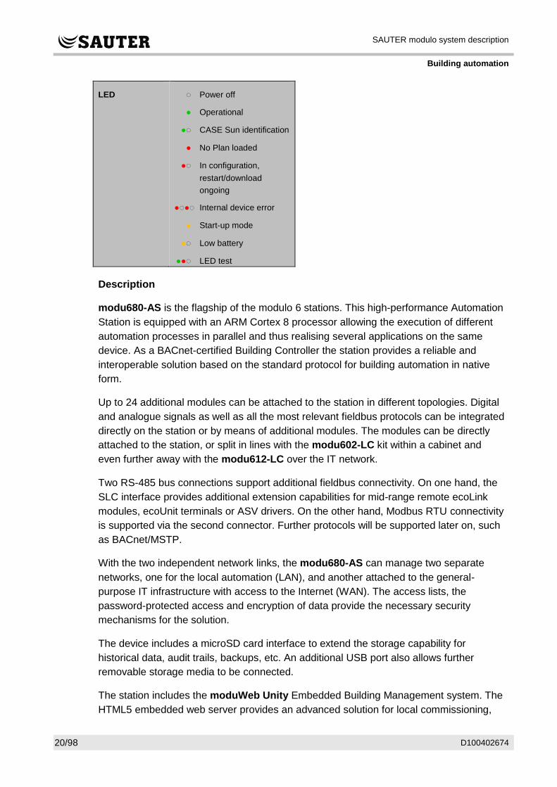
LED ◌ Power off
● Operational
●◌ CASE Sun identification
● No Plan loaded
●◌ In configuration,
restart/download
ongoing
●◌●◌ Internal device error
● Start-up mode
●◌ Low battery
●●◌ LED test
Description
modu680-AS is the flagship of the modulo 6 stations. This high-performance Automation
Station is equipped with an ARM Cortex 8 processor allowing the execution of different
automation processes in parallel and thus realising several applications on the same
device. As a BACnet-certified Building Controller the station provides a reliable and
interoperable solution based on the standard protocol for building automation in native
form.
Up to 24 additional modules can be attached to the station in different topologies. Digital
and analogue signals as well as all the most relevant fieldbus protocols can be integrated
directly on the station or by means of additional modules. The modules can be directly
attached to the station, or split in lines with the modu602-LC kit within a cabinet and
even further away with the modu612-LC over the IT network.
Two RS-485 bus connections support additional fieldbus connectivity. On one hand, the
SLC interface provides additional extension capabilities for mid-range remote ecoLink
modules, ecoUnit terminals or ASV drivers. On the other hand, Modbus RTU connectivity
is supported via the second connector. Further protocols will be supported later on, such
as BACnet/MSTP.
With the two independent network links, the modu680-AS can manage two separate
networks, one for the local automation (LAN), and another attached to the general-
purpose IT infrastructure with access to the Internet (WAN). The access lists, the
password-protected access and encryption of data provide the necessary security
mechanisms for the solution.
The device includes a microSD card interface to extend the storage capability for
historical data, audit trails, backups, etc. An additional USB port also allows further
removable storage media to be connected.
The station includes the moduWeb Unity Embedded Building Management system. The
HTML5 embedded web server provides an advanced solution for local commissioning,
SAUTER modulo system description
Building automation
D100402674
21/98
visualisation and control. The functionality can be extended to make a full-featured, local
management system for small and mid-sized projects out of the modu680-AS.
Commissioning and maintenance are made easy over the wireless Bluetooth connection
that provides access to the commissioning web server. It allows the visualisation of
modules and signals on the terminals as well as other configuration possibilities. As with
modu600-LO, the signals on the I/O modules can be overridden with the App over the
Bluetooth connection or with the web server.
The “Alive” signal can be used to monitor overall system functionality by another station.
The new CASE Suite paves the way for highly efficient engineering. A large library of
pre-defined solutions provides proven automation solutions for HVAC applications.
Maximum configuration
Up to 2 line breaks with the modu602-LC kit
Up to 24 modules overall (using modu601-LC)
Up to 5 Fieldbus modules directly attached to the station
Additional extension capability over SLC bus with up to 12 devices, including ASV
drives, ecoLink modules, ecoUnit terminals or FCCP200 terminals
Line terminator delivered with station (to be set up on the last module)
microSD interface
USB 2.0 interface
Bluetooth interface
SAUTER modulo system description
Building automation
D100402674
22/98
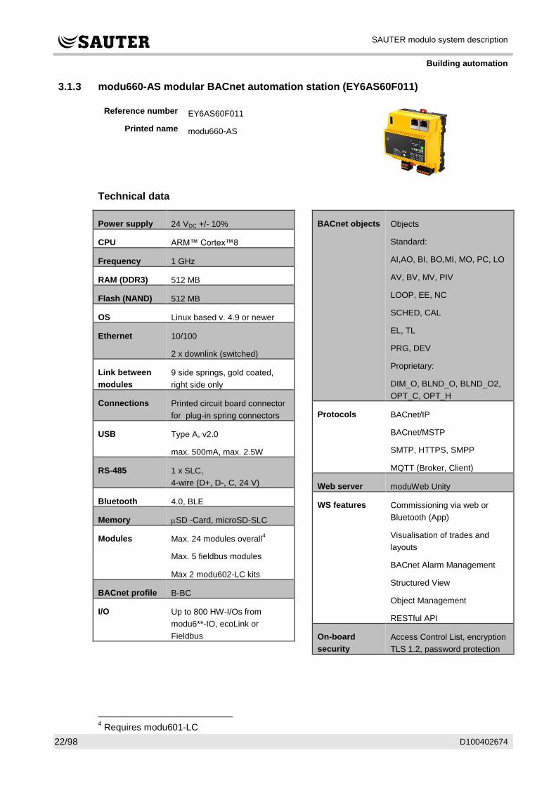
3.1.3 modu660-AS modular BACnet automation station (EY6AS60F011)
Reference number EY6AS60F011
Printed name modu660-AS
Technical data
Power supply 24 VDC +/- 10%
CPU ARM™ Cortex™8
Frequency 1 GHz
RAM (DDR3) 512 MB
Flash (NAND) 512 MB
OS Linux based v. 4.9 or newer
Ethernet 10/100
2 x downlink (switched)
Link between
modules
9 side springs, gold coated,
right side only
Connections Printed circuit board connector
for plug-in spring connectors
USB Type A, v2.0
max. 500mA, max. 2.5W
RS-485 1 x SLC,
4-wire (D+, D-, C, 24 V)
Bluetooth 4.0, BLE
Memory SD -Card, microSD-SLC
Modules Max. 24 modules overall4
Max. 5 fieldbus modules
Max 2 modu602-LC kits
BACnet profile B-BC
I/O Up to 800 HW-I/Os from
modu6**-IO, ecoLink or
Fieldbus
4 Requires modu601-LC
BACnet objects Objects
Standard:
AI,AO, BI, BO,MI, MO, PC, LO
AV, BV, MV, PIV
LOOP, EE, NC
SCHED, CAL
EL, TL
PRG, DEV
Proprietary:
DIM_O, BLND_O, BLND_O2,
OPT_C, OPT_H
Protocols BACnet/IP
BACnet/MSTP
SMTP, HTTPS, SMPP
MQTT (Broker, Client)
Web server moduWeb Unity
WS features Commissioning via web or
Bluetooth (App)
Visualisation of trades and
layouts
BACnet Alarm Management
Structured View
Object Management
RESTful API
On-board
security
Access Control List, encryption
TLS 1.2, password protection
SAUTER modulo system description
Building automation
D100402674
23/98
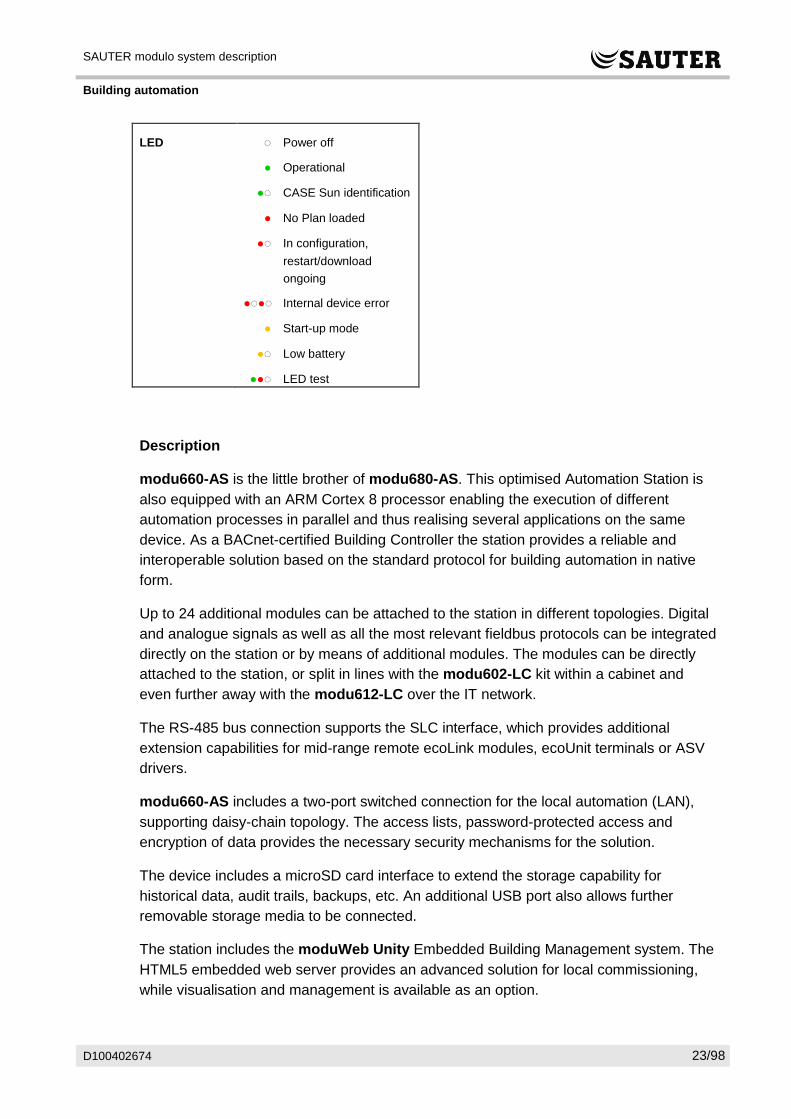
LED ◌ Power off
● Operational
●◌ CASE Sun identification
● No Plan loaded
●◌ In configuration,
restart/download
ongoing
●◌●◌ Internal device error
● Start-up mode
●◌ Low battery
●●◌ LED test
Description
modu660-AS is the little brother of modu680-AS. This optimised Automation Station is
also equipped with an ARM Cortex 8 processor enabling the execution of different
automation processes in parallel and thus realising several applications on the same
device. As a BACnet-certified Building Controller the station provides a reliable and
interoperable solution based on the standard protocol for building automation in native
form.
Up to 24 additional modules can be attached to the station in different topologies. Digital
and analogue signals as well as all the most relevant fieldbus protocols can be integrated
directly on the station or by means of additional modules. The modules can be directly
attached to the station, or split in lines with the modu602-LC kit within a cabinet and
even further away with the modu612-LC over the IT network.
The RS-485 bus connection supports the SLC interface, which provides additional
extension capabilities for mid-range remote ecoLink modules, ecoUnit terminals or ASV
drivers.
modu660-AS includes a two-port switched connection for the local automation (LAN),
supporting daisy-chain topology. The access lists, password-protected access and
encryption of data provides the necessary security mechanisms for the solution.
The device includes a microSD card interface to extend the storage capability for
historical data, audit trails, backups, etc. An additional USB port also allows further
removable storage media to be connected.
The station includes the moduWeb Unity Embedded Building Management system. The
HTML5 embedded web server provides an advanced solution for local commissioning,
while visualisation and management is available as an option.
SAUTER modulo system description
Building automation
D100402674
24/98
Commissioning and maintenance are made easy over the wireless Bluetooth connection
that provides access to the commissioning web server. It allows the visualisation of
modules and signals on the terminals as well as other configuration possibilities. As with
modu600-LO, the signals on the I/O modules can be overridden with the App over the
Bluetooth connection or with the web server.
The “Alive” signal can be used to monitor overall system functionality by another station.
The new CASE Suite paves the way for highly efficient engineering. A large library of
pre-defined solutions provides proven automation solutions for HVAC applications.
Maximum configuration
Up to 2 line breaks with the modu602-LC kit
Up to 24 modules overall (using modu601-LC)
Up to 5 fieldbus modules directly attached to the station
Additional extension capability over SLC bus with up to 12 devices, including ASV
drives, ecoLink modules, ecoUnit terminals or FCCP200 terminals
Line terminator delivered with station (to be set up on the last module)
microSD interface
USB 2.0 interface
Bluetooth interface
SAUTER modulo system description
Building automation
D100402674
25/98
3.2 modulo 6 Integration Solutions
The modulo 6 integration solutions provide additional flexibility in the configuration of the
automation set-up. The modu602-LC kit allows the splitting of I/O module lines into
different rows within the cabinet, providing short-range connectivity over a point-to-point
connection. modu612-LC, on the other hand, enables long-range connections to be set
up via the IP network. modu601-LC provides additional flexibility, facilitating a power
supply to the I/O modules during short station interruptions, or even having a separated
supply.
3.2.1 Overview
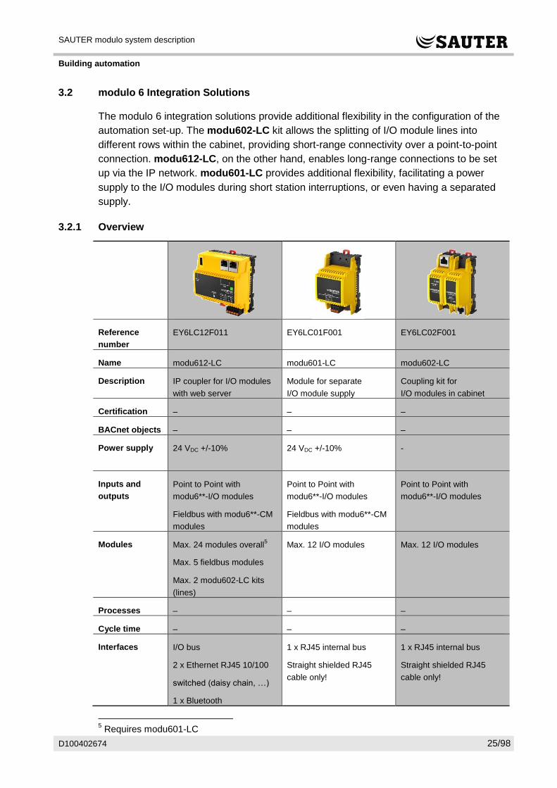
Reference
number
EY6LC12F011 EY6LC01F001 EY6LC02F001
Name modu612-LC modu601-LC modu602-LC
Description IP coupler for I/O modules
with web server
Module for separate
I/O module supply
Coupling kit for
I/O modules in cabinet
Certification – – –
BACnet objects – – –
Power supply 24 VDC +/-10% 24 VDC +/-10% -
Inputs and
outputs
Point to Point with
modu6**-I/O modules
Fieldbus with modu6**-CM
modules
Point to Point with
modu6**-I/O modules
Fieldbus with modu6**-CM
modules
Point to Point with
modu6**-I/O modules
Modules Max. 24 modules overall5
Max. 5 fieldbus modules
Max. 2 modu602-LC kits
(lines)
Max. 12 I/O modules Max. 12 I/O modules
Processes – – –
Cycle time – – –
Interfaces I/O bus
2 x Ethernet RJ45 10/100
switched (daisy chain, …)
1 x Bluetooth
1 x RJ45 internal bus
Straight shielded RJ45
cable only!
1 x RJ45 internal bus
Straight shielded RJ45
cable only!
5 Requires modu601-LC
SAUTER modulo system description
Building automation
D100402674
26/98
RTC CR2032 battery
(exchangeable)
– –
Dimensions W (↔) 87.5 mm (5 TE)
L (↕) 100 mm
H (↨) 58.3 mm
W (↔) 55.7 mm (3 TE)
L (↕) 100 mm
H (↨) 58.3 mm
W (↔) 29.45 mm (1.5
TE)
L (↕) 100 mm
H (↨) 58.3 mm
SAUTER modulo system description
Building automation
D100402674
27/98
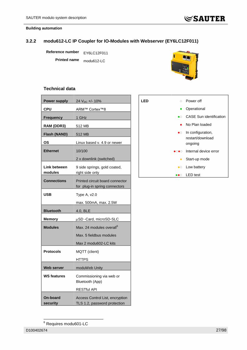
3.2.2 modu612-LC IP Coupler for IO-Modules with Webserver (EY6LC12F011)
Reference number EY6LC12F011
Printed name modu612-LC
Technical data
Power supply 24 VDC +/- 10%
CPU ARM™ Cortex™8
Frequency 1 GHz
RAM (DDR3) 512 MB
Flash (NAND) 512 MB
OS Linux based v. 4.9 or newer
Ethernet 10/100
2 x downlink (switched)
Link between
modules
9 side springs, gold coated,
right side only
Connections Printed circuit board connector
for plug-in spring connectors
USB Type A, v2.0
max. 500mA, max. 2.5W
Bluetooth 4.0, BLE
Memory SD -Card, microSD-SLC
Modules Max. 24 modules overall6
Max. 5 fieldbus modules
Max 2 modu602-LC kits
Protocols MQTT (client)
HTTPS
Web server moduWeb Unity
WS features Commissioning via web or
Bluetooth (App)
RESTful API
On-board
security
Access Control List, encryption
TLS 1.2, password protection
6 Requires modu601-LC
LED ◌ Power off
● Operational
●◌ CASE Sun identification
● No Plan loaded
●◌ In configuration,
restart/download
ongoing
●◌●◌ Internal device error
● Start-up mode
●◌ Low battery
●●◌ LED test
SAUTER modulo system description
Building automation
D100402674
28/98
Description
modu612-LC is a Link Coupler allowing the remote installation of COM- and I/O modules
and allowing communication with a Building Controller over the IP network, for example a
modu680-AS, or to the SAUTER Cloud. The modu612-LC supports the same number
of COM and I/O modules (24) as the Building Controller and is intended to extend the
number of data points controlled by a Building Controller.
modu612-LC relies on the lightweight MQTT protocol to communicate with the parent
Building Controllers (modu680-AS, modu660-AS) or to the Sauter Cloud which act as
MQTT brokers. modu612-LC operates as a MQTT client, publishing the values of the
I/Os and subscribing to relevant properties of the related BACnet objects in the station.
Thus, the Automation Station has updated values from the sensors and the modu612-
LC can provide the information needed to the I/O modules and the attached modu600-
LOs. MQTT is one of the most widespread protocols for BIoT and also supports TLS
encryption, thus providing the required privacy of the communication, even over the
Internet to the Cloud.
Maximum configuration
Up to 2 line breaks with the modu602-LC kit
Up to 24 modules overall (using modu601-LC)
Up to 5 fieldbus modules directly attached to the station
Line terminator delivered with station (to be set on the last module)
USB 2.0 interface
Bluetooth interface
SAUTER modulo system description
D100402674
29/98
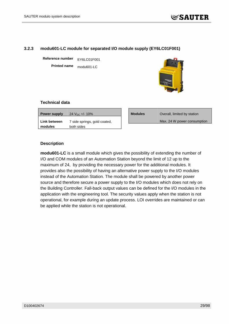
3.2.3 modu601-LC module for separated I/O module supply (EY6LC01F001)
Reference number EY6LC01F001
Printed name modu601-LC
Technical data
Power supply 24 VDC +/- 10%
Link between
modules
7 side springs, gold coated,
both sides
Modules Overall, limited by station
Max. 24 W power consumption
Description
modu601-LC is a small module which gives the possibility of extending the number of
I/O and COM modules of an Automation Station beyond the limit of 12 up to the
maximum of 24, by providing the necessary power for the additional modules. It
provides also the possibility of having an alternative power supply to the I/O modules
instead of the Automation Station. The module shall be powered by another power
source and therefore secure a power supply to the I/O modules which does not rely on
the Building Controller. Fall-back output values can be defined for the I/O modules in the
application with the engineering tool. The security values apply when the station is not
operational, for example during an update process. LOI overrides are maintained or can
be applied while the station is not operational.
SAUTER modulo system description
D100402674
30/98
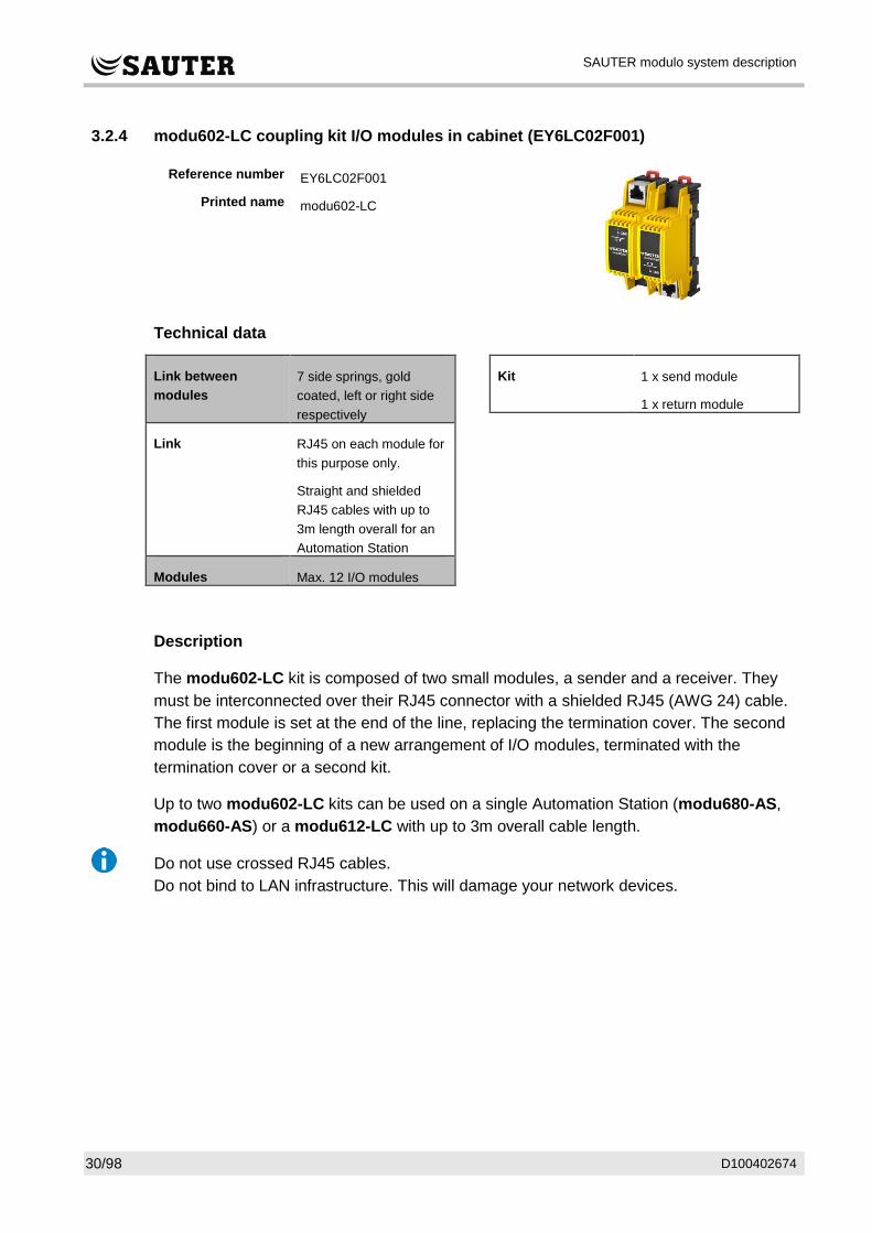
3.2.4 modu602-LC coupling kit I/O modules in cabinet (EY6LC02F001)
Reference number EY6LC02F001
Printed name modu602-LC
Technical data
Link between
modules
7 side springs, gold
coated, left or right side
respectively
Link RJ45 on each module for
this purpose only.
Straight and shielded
RJ45 cables with up to
3m length overall for an
Automation Station
Modules Max. 12 I/O modules
Kit 1 x send module
1 x return module
Description
The modu602-LC kit is composed of two small modules, a sender and a receiver. They
must be interconnected over their RJ45 connector with a shielded RJ45 (AWG 24) cable.
The first module is set at the end of the line, replacing the termination cover. The second
module is the beginning of a new arrangement of I/O modules, terminated with the
termination cover or a second kit.
Up to two modu602-LC kits can be used on a single Automation Station (modu680-AS,
modu660-AS) or a modu612-LC with up to 3m overall cable length.
Do not use crossed RJ45 cables.
Do not bind to LAN infrastructure. This will damage your network devices.
SAUTER modulo system description
D100402674
31/98
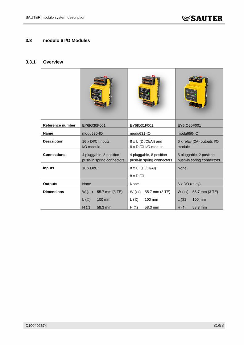
3.3 modulo 6 I/O Modules
3.3.1 Overview
Reference number EY6IO30F001 EY6IO31F001 EY6IO50F001
Name modu630-IO modu631-IO modu650-IO
Description 16 x DI/CI inputs
I/O module
8 x UI(DI/CI/AI) and
8 x DI/CI I/O module
6 x relay (2A) outputs I/O
module
Connections 4 pluggable, 8 position
push-in spring connectors
4 pluggable, 8 position
push-in spring connectors
6 pluggable, 2 position
push-in spring connectors
Inputs 16 x DI/CI 8 x UI (DI/CI/AI)
8 x DI/CI
None
Outputs None None 6 x DO (relay)
Dimensions W (↔) 55.7 mm (3 TE)
L (↕) 100 mm
H (↨) 58.3 mm
W (↔) 55.7 mm (3 TE)
L (↕) 100 mm
H (↨) 58.3 mm
W (↔) 55.7 mm (3 TE)
L (↕) 100 mm
H (↨) 58.3 mm
SAUTER modulo system description
D100402674
32/98
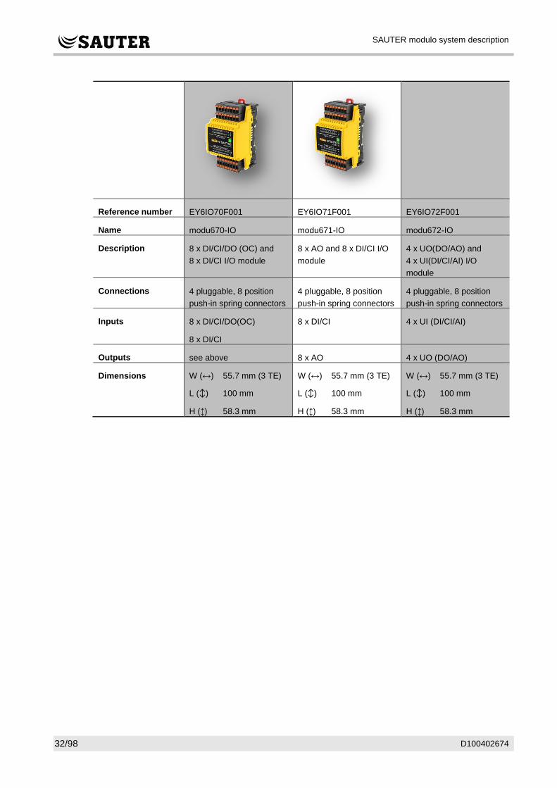
Reference number EY6IO70F001 EY6IO71F001 EY6IO72F001
Name modu670-IO modu671-IO modu672-IO
Description 8 x DI/CI/DO (OC) and
8 x DI/CI I/O module
8 x AO and 8 x DI/CI I/O
module
4 x UO(DO/AO) and
4 x UI(DI/CI/AI) I/O
module
Connections 4 pluggable, 8 position
push-in spring connectors
4 pluggable, 8 position
push-in spring connectors
4 pluggable, 8 position
push-in spring connectors
Inputs 8 x DI/CI/DO(OC)
8 x DI/CI
8 x DI/CI 4 x UI (DI/CI/AI)
Outputs see above 8 x AO 4 x UO (DO/AO)
Dimensions W (↔) 55.7 mm (3 TE)
L (↕) 100 mm
H (↨) 58.3 mm
W (↔) 55.7 mm (3 TE)
L (↕) 100 mm
H (↨) 58.3 mm
W (↔) 55.7 mm (3 TE)
L (↕) 100 mm
H (↨) 58.3 mm
SAUTER modulo system description
D100402674
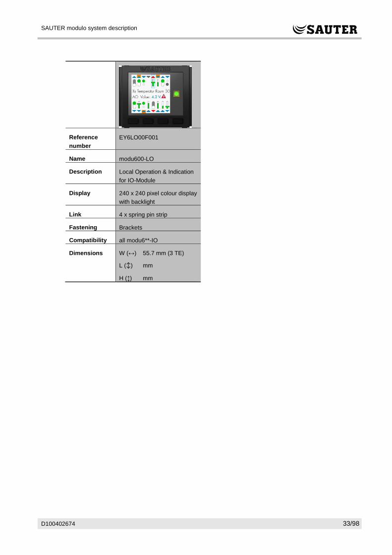
33/98
Reference
number
EY6LO00F001
Name modu600-LO
Description Local Operation & Indication
for IO-Module
Display 240 x 240 pixel colour display
with backlight
Link 4 x spring pin strip
Fastening Brackets
Compatibility all modu6**-IO
Dimensions W (↔) 55.7 mm (3 TE)
L (↕) mm
H (↨) mm
SAUTER modulo system description
D100402674
34/98
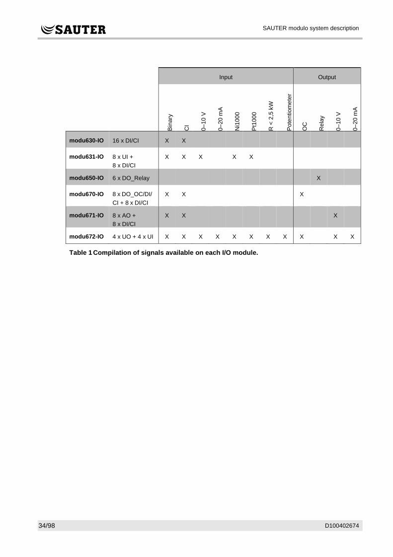
Input Output
Bin
ary
CI
0–
10
V
0–
20
mA
Ni1
00
0
Pt1
00
0
R <
2,5
kW
Po
ten
tio
me
ter
OC
Re
lay
0–
10
V
0–
20
mA
modu630-IO 16 x DI/CI X X
modu631-IO 8 x UI +
8 x DI/CI
X X X X X
modu650-IO 6 x DO_Relay X
modu670-IO 8 x DO_OC/DI/
CI + 8 x DI/CI
X X X
modu671-IO 8 x AO +
8 x DI/CI
X X X
modu672-IO 4 x UO + 4 x UI X X X X X X X X X X X
Table 1 Compilation of signals available on each I/O module.
SAUTER modulo system description
D100402674
35/98
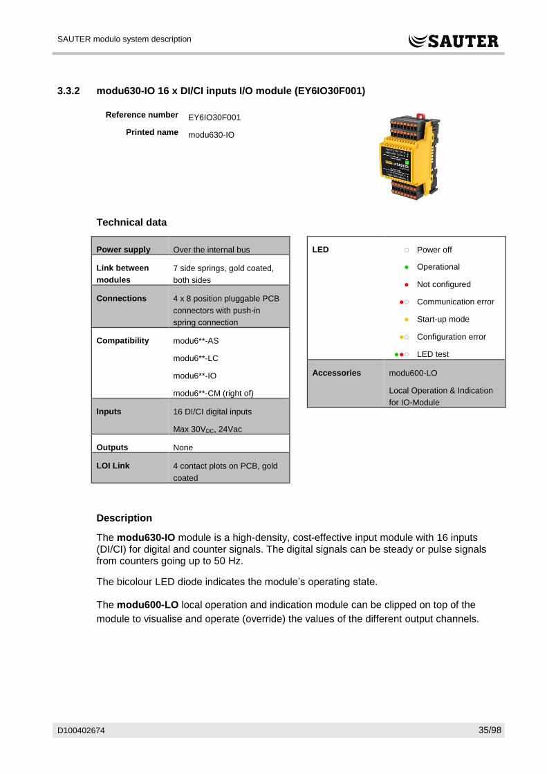
3.3.2 modu630-IO 16 x DI/CI inputs I/O module (EY6IO30F001)
Reference number EY6IO30F001
Printed name modu630-IO
Technical data
Power supply Over the internal bus
Link between
modules
7 side springs, gold coated,
both sides
Connections 4 x 8 position pluggable PCB
connectors with push-in
spring connection
Compatibility modu6**-AS
modu6**-LC
modu6**-IO
modu6**-CM (right of)
Inputs 16 DI/CI digital inputs
Max 30VDC, 24Vac
Outputs None
LOI Link 4 contact plots on PCB, gold
coated
LED ◌ Power off
● Operational
● Not configured
●◌ Communication error
● Start-up mode
●◌ Configuration error
●●◌ LED test
Accessories modu600-LO
Local Operation & Indication
for IO-Module
Description
The modu630-IO module is a high-density, cost-effective input module with 16 inputs (DI/CI) for digital and counter signals. The digital signals can be steady or pulse signals from counters going up to 50 Hz.
The bicolour LED diode indicates the module’s operating state.
The modu600-LO local operation and indication module can be clipped on top of the
module to visualise and operate (override) the values of the different output channels.
SAUTER modulo system description
D100402674
36/98
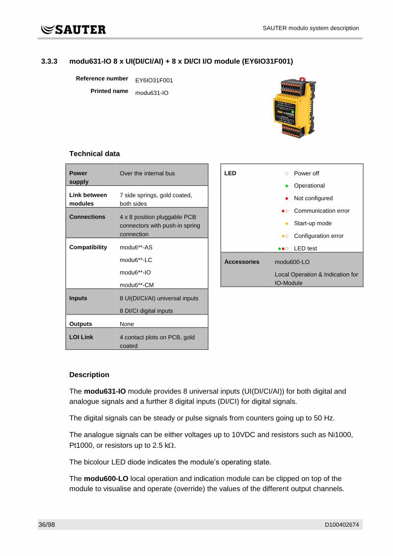
3.3.3 modu631-IO 8 x UI(DI/CI/AI) + 8 x DI/CI I/O module (EY6IO31F001)
Reference number EY6IO31F001
Printed name modu631-IO
Technical data
Power
supply
Over the internal bus
Link between
modules
7 side springs, gold coated,
both sides
Connections 4 x 8 position pluggable PCB
connectors with push-in spring
connection
Compatibility modu6**-AS
modu6**-LC
modu6**-IO
modu6**-CM
Inputs 8 UI(DI/CI/AI) universal inputs
8 DI/CI digital inputs
Outputs None
LOI Link 4 contact plots on PCB, gold
coated
LED ◌ Power off
● Operational
● Not configured
●◌ Communication error
● Start-up mode
●◌ Configuration error
●●◌ LED test
Accessories modu600-LO
Local Operation & Indication for
IO-Module
Description
The modu631-IO module provides 8 universal inputs (UI(DI/CI/AI)) for both digital and
analogue signals and a further 8 digital inputs (DI/CI) for digital signals.
The digital signals can be steady or pulse signals from counters going up to 50 Hz.
The analogue signals can be either voltages up to 10VDC and resistors such as Ni1000,
Pt1000, or resistors up to 2.5 k.
The bicolour LED diode indicates the module’s operating state.
The modu600-LO local operation and indication module can be clipped on top of the
module to visualise and operate (override) the values of the different output channels.
SAUTER modulo system description
D100402674
37/98
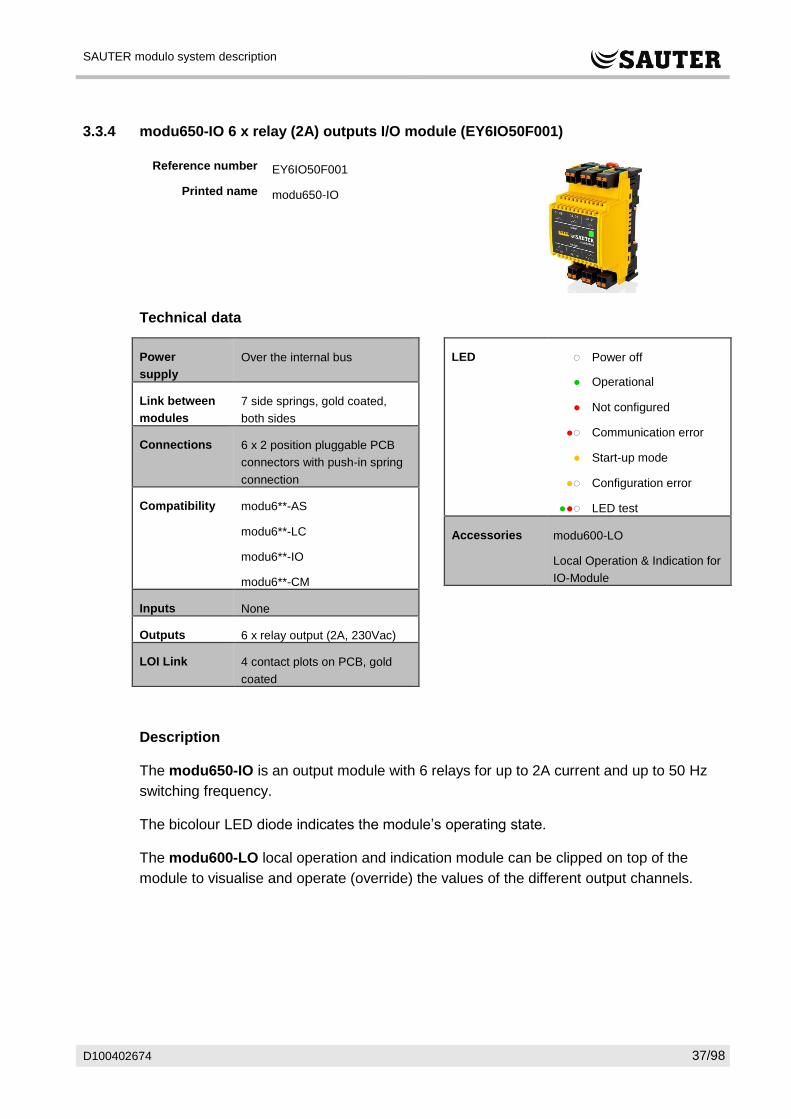
3.3.4 modu650-IO 6 x relay (2A) outputs I/O module (EY6IO50F001)
Reference number EY6IO50F001
Printed name modu650-IO
Technical data
Power
supply
Over the internal bus
Link between
modules
7 side springs, gold coated,
both sides
Connections 6 x 2 position pluggable PCB
connectors with push-in spring
connection
Compatibility modu6**-AS
modu6**-LC
modu6**-IO
modu6**-CM
Inputs None
Outputs 6 x relay output (2A, 230Vac)
LOI Link 4 contact plots on PCB, gold
coated
LED ◌ Power off
● Operational
● Not configured
●◌ Communication error
● Start-up mode
●◌ Configuration error
●●◌ LED test
Accessories modu600-LO
Local Operation & Indication for
IO-Module
Description
The modu650-IO is an output module with 6 relays for up to 2A current and up to 50 Hz
switching frequency.
The bicolour LED diode indicates the module’s operating state.
The modu600-LO local operation and indication module can be clipped on top of the
module to visualise and operate (override) the values of the different output channels.
SAUTER modulo system description
D100402674
38/98
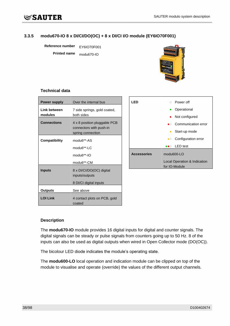
3.3.5 modu670-IO 8 x DI/CI/DO(OC) + 8 x DI/CI I/O module (EY6IO70F001)
Reference number EY6IO70F001
Printed name modu670-IO
Technical data
Power supply Over the internal bus
Link between
modules
7 side springs, gold coated,
both sides
Connections 4 x 8 position pluggable PCB
connectors with push-in
spring connection
Compatibility modu6**-AS
modu6**-LC
modu6**-IO
modu6**-CM
Inputs 8 x DI/CI/DO(OC) digital
inputs/outputs
8 DI/CI digital inputs
Outputs See above
LOI Link 4 contact plots on PCB, gold
coated
LED ◌ Power off
● Operational
● Not configured
●◌ Communication error
● Start-up mode
●◌ Configuration error
●●◌ LED test
Accessories modu600-LO
Local Operation & Indication
for IO-Module
Description
The modu670-IO module provides 16 digital inputs for digital and counter signals. The
digital signals can be steady or pulse signals from counters going up to 50 Hz. 8 of the
inputs can also be used as digital outputs when wired in Open Collector mode (DO(OC)).
The bicolour LED diode indicates the module’s operating state.
The modu600-LO local operation and indication module can be clipped on top of the
module to visualise and operate (override) the values of the different output channels.

SAUTER modulo system description
D100402674
39/98
3.3.6 modu671-IO 8 x AO + 8 x DI/CI IO-Module (EY6IO71F001)
Reference number EY6IO71F001
Printed name modu671-IO
Technical data
Power supply Over the internal bus
Link between
modules
7 side springs, gold coated,
both sides
Connections 4 x 8 position pluggable PCB
connectors with push-in
spring connection
Compatibility modu6**-AS
modu6**-LC
modu6**-IO
modu6**-CM
Inputs 8 DI/CI digital inputs
Outputs 8 x AO analogue outputs
LOI Link 4 contact plots on PCB, gold
coated
LED ◌ Power off
● Operational
● Not configured
●◌ Communication error
● Start-up mode
● Configuration error
●●◌ LED test
Accessories modu600-LO
Local Operation & Indication
for IO-Module
Description
The modu671-IO provides up to 8 analogue outputs (AO) for both voltages up to 10V
and current up to 20 mA. An additional 8 digital inputs (DI/CI) are also available. The
digital signals can be steady or pulse signals from counters going up to 50 Hz.
The bicolour LED diode indicates the module’s operating state.
The modu600-LO local operation and indication module can be clipped on top of the
module to visualise and operate (override) the values of the different output channels.
SAUTER modulo system description
D100402674
40/98
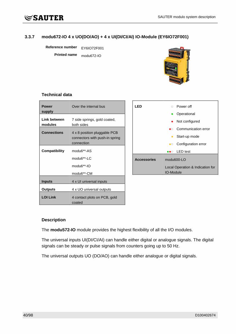
3.3.7 modu672-IO 4 x UO(DO/AO) + 4 x UI(DI/CI/AI) IO-Module (EY6IO72F001)
Reference number EY6IO72F001
Printed name modu672-IO
Technical data
Power
supply
Over the internal bus
Link between
modules
7 side springs, gold coated,
both sides
Connections 4 x 8 position pluggable PCB
connectors with push-in spring
connection
Compatibility modu6**-AS
modu6**-LC
modu6**-IO
modu6**-CM
Inputs 4 x UI universal inputs
Outputs 4 x UO universal outputs
LOI Link 4 contact plots on PCB, gold
coated
LED ◌ Power off
● Operational
● Not configured
●◌ Communication error
● Start-up mode
●◌ Configuration error
●●◌ LED test
Accessories modu600-LO
Local Operation & Indication for
IO-Module
Description
The modu572-IO module provides the highest flexibility of all the I/O modules.
The universal inputs UI(DI/CI/AI) can handle either digital or analogue signals. The digital
signals can be steady or pulse signals from counters going up to 50 Hz.
The universal outputs UO (DO/AO) can handle either analogue or digital signals.
SAUTER modulo system description
D100402674
41/98
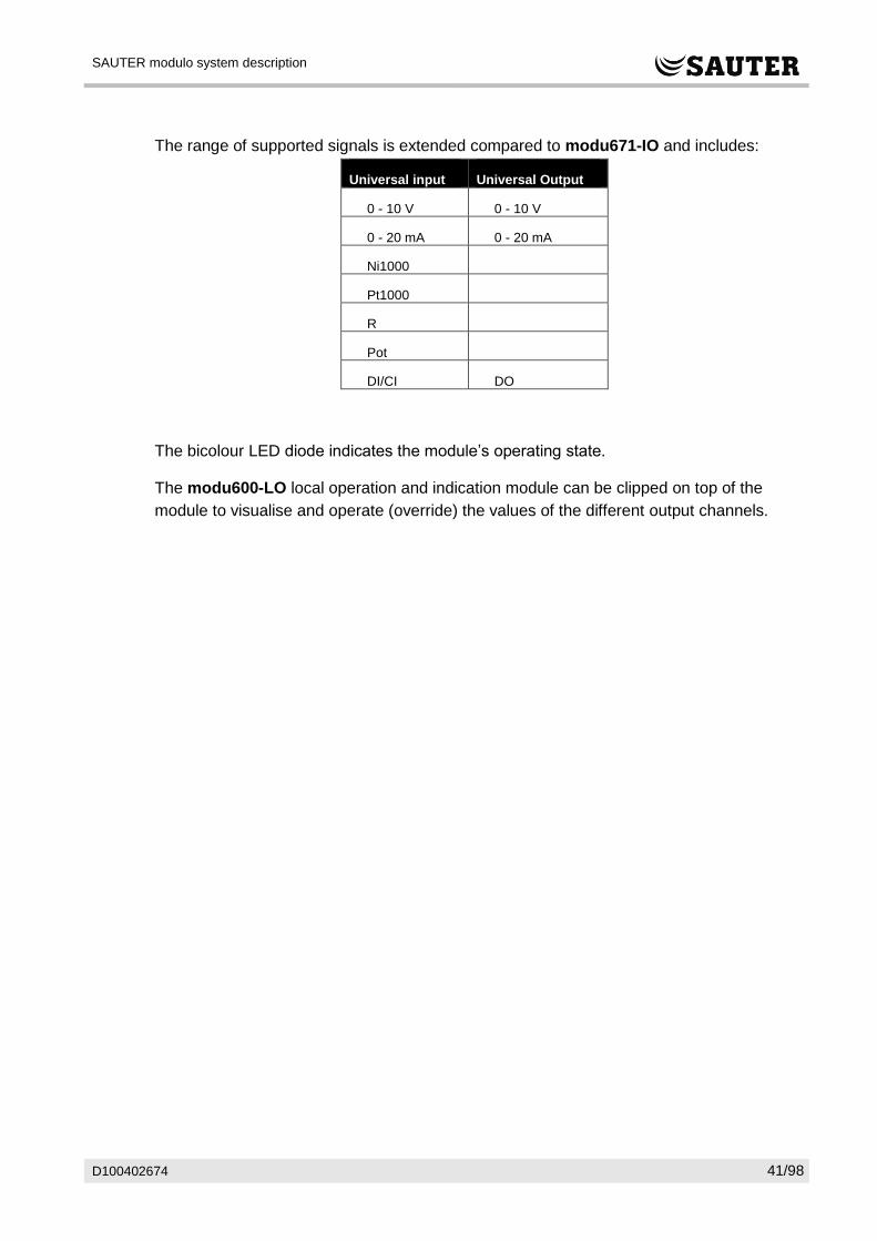
The range of supported signals is extended compared to modu671-IO and includes:
Universal input Universal Output
0 - 10 V 0 - 10 V
0 - 20 mA 0 - 20 mA
Ni1000
Pt1000
R
Pot
DI/CI DO
The bicolour LED diode indicates the module’s operating state.
The modu600-LO local operation and indication module can be clipped on top of the
module to visualise and operate (override) the values of the different output channels.
SAUTER modulo system description
D100402674
42/98
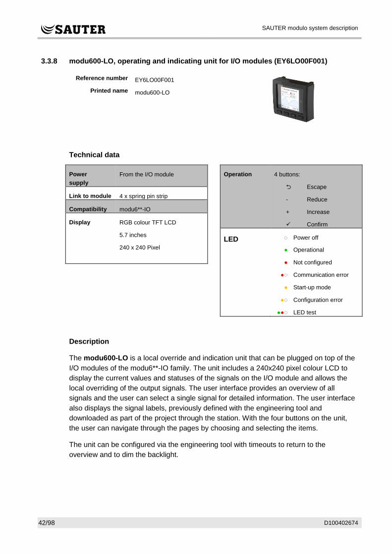
3.3.8 modu600-LO, operating and indicating unit for I/O modules (EY6LO00F001)
Reference number EY6LO00F001
Printed name modu600-LO
Technical data
Power
supply
From the I/O module
Link to module 4 x spring pin strip
Compatibility modu6**-IO
Display RGB colour TFT LCD
5.7 inches
240 x 240 Pixel
Operation 4 buttons:
Escape
- Reduce
+ Increase
Confirm
LED ◌ Power off
● Operational
● Not configured
●◌ Communication error
● Start-up mode
●◌ Configuration error
●●◌ LED test
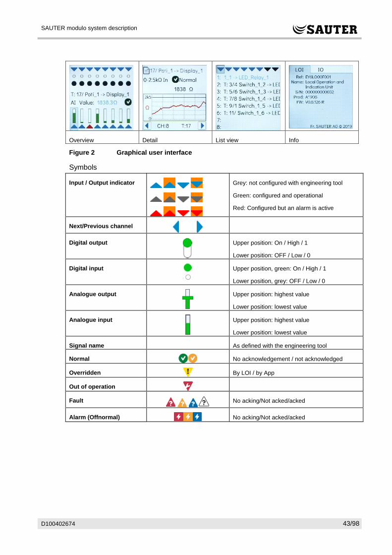
Description
The modu600-LO is a local override and indication unit that can be plugged on top of the
I/O modules of the modu6**-IO family. The unit includes a 240x240 pixel colour LCD to
display the current values and statuses of the signals on the I/O module and allows the
local overriding of the output signals. The user interface provides an overview of all
signals and the user can select a single signal for detailed information. The user interface
also displays the signal labels, previously defined with the engineering tool and
downloaded as part of the project through the station. With the four buttons on the unit,
the user can navigate through the pages by choosing and selecting the items.
The unit can be configured via the engineering tool with timeouts to return to the
overview and to dim the backlight.
SAUTER modulo system description
D100402674
43/98
Overview Detail List view Info
Figure 2 Graphical user interface
Symbols
Input / Output indicator
Grey: not configured with engineering tool
Green: configured and operational
Red: Configured but an alarm is active
Next/Previous channel
Digital output
Upper position: On / High / 1
Lower position: OFF / Low / 0
Digital input
Upper position, green: On / High / 1
Lower position, grey: OFF / Low / 0
Analogue output
Upper position: highest value
Lower position: lowest value
Analogue input
Upper position: highest value
Lower position: lowest value
Signal name As defined with the engineering tool
Normal No acknowledgement / not acknowledged
Overridden By LOI / by App
Out of operation
Fault
No acking/Not acked/acked
Alarm (Offnormal) No acking/Not acked/acked
SAUTER modulo system description
D100402674
44/98
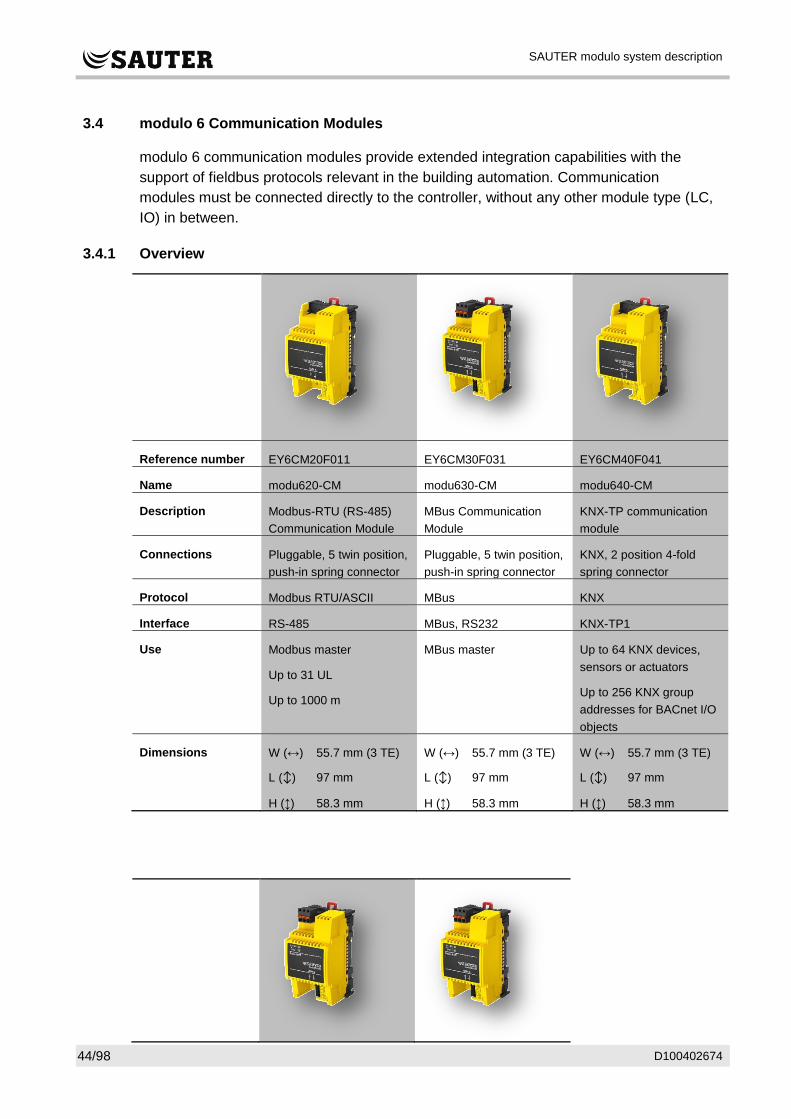
3.4 modulo 6 Communication Modules
modulo 6 communication modules provide extended integration capabilities with the
support of fieldbus protocols relevant in the building automation. Communication
modules must be connected directly to the controller, without any other module type (LC,
IO) in between.
3.4.1 Overview
Reference number EY6CM20F011 EY6CM30F031 EY6CM40F041
Name modu620-CM modu630-CM modu640-CM
Description Modbus-RTU (RS-485)
Communication Module
MBus Communication
Module
KNX-TP communication
module
Connections Pluggable, 5 twin position,
push-in spring connector
Pluggable, 5 twin position,
push-in spring connector
KNX, 2 position 4-fold
spring connector
Protocol Modbus RTU/ASCII MBus KNX
Interface RS-485 MBus, RS232 KNX-TP1
Use Modbus master
Up to 31 UL
Up to 1000 m
MBus master Up to 64 KNX devices,
sensors or actuators
Up to 256 KNX group
addresses for BACnet I/O
objects
Dimensions W (↔) 55.7 mm (3 TE)
L (↕) 97 mm
H (↨) 58.3 mm
W (↔) 55.7 mm (3 TE)
L (↕) 97 mm
H (↨) 58.3 mm
W (↔) 55.7 mm (3 TE)
L (↕) 97 mm
H (↨) 58.3 mm
SAUTER modulo system description
D100402674
45/98
Reference number EY6CM50F051 EY6CM60F061
Name modu650-CM modu660-CM
Description DALI communication
module
SMI communication
module
Connections 4 position spring-cage
connector
4 position spring-cage
connector
Protocol DALI SMI
Interface DALI SMI
Use DALI ballasts and sensors Up to 16 actuators
Up to 128 SMI functions
for BACnet I/O objects for
up to 16 single and group
addresses each
Dimensions W (↔) 55.7 mm (3 TE)
L (↕) 97 mm
H (↨) 58.3 mm
W (↔) 55.7 mm (3 TE)
L (↕) 97 mm
H (↨) 58.3 mm
SAUTER modulo system description
D100402674
46/98
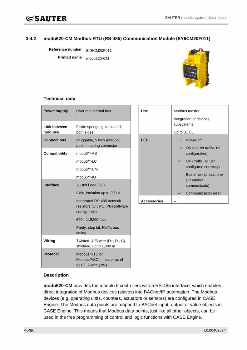
3.4.2 modu620-CM Modbus-RTU (RS-485) Communication Module (EY6CM20F011)
Reference number EY6CM20F011
Printed name modu620-CM
Technical data
Power supply Over the internal bus
Link between
modules
9 side springs, gold coated,
both sides
Connections Pluggable, 5 twin position,
push-in spring connector
Compatibility modu6**-AS
modu6**-LC
modu6**-CM
modu6**-IO
Interface ½ Unit Load (UL)
Galv. Isolation up to 300 V
Integrated RS-485 network
resistors (LT, PU, PD) software
configurable
600 - 115200 bit/s
Parity, stop bit, Rx/Tx bus
timing
Wiring Twisted, 4-/3-wire (D+, D-, C),
shielded, up to 1,000 m
Protocol Modbus/RTU or
Modbus/ASCII, master as of
v1.02, 2-wire (2W)
Use Modbus master
Integration of devices,
subsystems
Up to 31 UL
LED ◌ Power off
● OK (but no traffic, no
configuration)
●◌ OK (traffic, all DP
configured correctly)
● Bus error (at least one
DP cannot
communicate)
●◌ Communication error
Accessories –
Description
modu620-CM provides the modulo 6 controllers with a RS-485 interface, which enables
direct integration of Modbus devices (slaves) into BACnet/IP automation. The Modbus
devices (e.g. operating units, counters, actuators or sensors) are configured in CASE
Engine. The Modbus data points are mapped to BACnet input, output or value objects in
CASE Engine. This means that Modbus data points, just like all other objects, can be
used in the free programming of control and logic functions with CASE Engine.
SAUTER modulo system description
D100402674
47/98
The RS-485 network for fieldbus protocols must be implemented according to
ANSI/TIA/EIA-485-A (half-duplex (D+/D-), galvanically isolated (COM reference),
network resistors with pull-up (PU), pull-down (PD), line end resistors (LT: line
termination)). With the Modbus module configuration, the resistors can be switched on or
off via software. It is recommended to use a shielded twisted cable (1x2+1 wire, 2x2
wire) specifically for RS-485. JYST-Y cables with a cable impedance of 100 - 120 Ohm
and sufficient diameter (0.8 mm2 resp. 0.5 mm2) are also possible. The cable must be
routed in a line topology and the shield must be connected to the earth in one place. The
maximum cable length is 1000 m. The baud rate can be 600 up to 115.2 k bit/s. The
Modbus module as the master also supports different communication parameters
simultaneously (e.g. baud rates, device timings, Modbus mode (RTU/ASCII)).
Before commissioning, the Modbus devices and their supported functions must be
checked and the devices addressed and configured. The supported functions are then
parameterised in CASE Engine. The Modbus master function is configured in the module
configuration, the individual specific device parameters in the device table, and the
Modbus function (function code) in the BACnet I/O/V blocks.
For easy commissioning and maintenance, a virtual serial port can be activated on the
station so that conventional Modbus master tools can set up a direct connection to the
Modbus devices via IP/Ethernet without additional RS-485 converters.
SAUTER modulo system description
D100402674
48/98
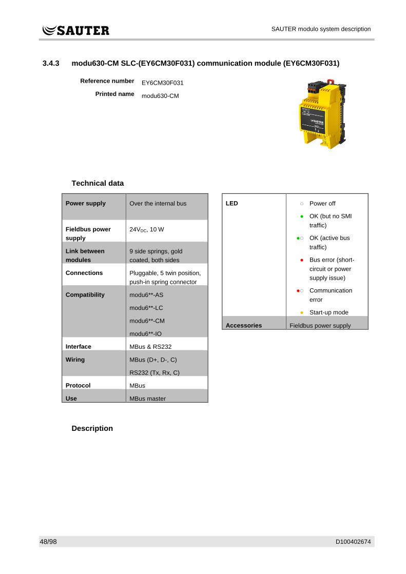
3.4.3 modu630-CM SLC-(EY6CM30F031) communication module (EY6CM30F031)
Reference number EY6CM30F031
Printed name modu630-CM
Technical data
Power supply Over the internal bus
Fieldbus power
supply
24VDC, 10 W
Link between
modules
9 side springs, gold
coated, both sides
Connections Pluggable, 5 twin position,
push-in spring connector
Compatibility modu6**-AS
modu6**-LC
modu6**-CM
modu6**-IO
Interface MBus & RS232
Wiring MBus (D+, D-, C)
RS232 (Tx, Rx, C)
Protocol MBus
Use MBus master
LED ◌ Power off
● OK (but no SMI
traffic)
●◌ OK (active bus
traffic)
● Bus error (short-
circuit or power
supply issue)
●◌ Communication
error
● Start-up mode
Accessories Fieldbus power supply
Description
SAUTER modulo system description
D100402674
49/98
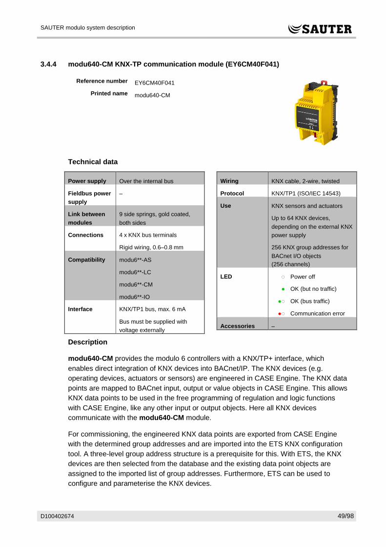
3.4.4 modu640-CM KNX-TP communication module (EY6CM40F041)
Reference number EY6CM40F041
Printed name modu640-CM
Technical data
Power supply Over the internal bus
Fieldbus power
supply
–
Link between
modules
9 side springs, gold coated,
both sides
Connections 4 x KNX bus terminals
Rigid wiring, 0.6–0.8 mm
Compatibility modu6**-AS
modu6**-LC
modu6**-CM
modu6**-IO
Interface KNX/TP1 bus, max. 6 mA
Bus must be supplied with
voltage externally
Wiring KNX cable, 2-wire, twisted
Protocol KNX/TP1 (ISO/IEC 14543)
Use KNX sensors and actuators
Up to 64 KNX devices,
depending on the external KNX
power supply
256 KNX group addresses for
BACnet I/O objects
(256 channels)
LED ◌ Power off
● OK (but no traffic)
●◌ OK (bus traffic)
●◌ Communication error
Accessories –
Description
modu640-CM provides the modulo 6 controllers with a KNX/TP+ interface, which
enables direct integration of KNX devices into BACnet/IP. The KNX devices (e.g.
operating devices, actuators or sensors) are engineered in CASE Engine. The KNX data
points are mapped to BACnet input, output or value objects in CASE Engine. This allows
KNX data points to be used in the free programming of regulation and logic functions
with CASE Engine, like any other input or output objects. Here all KNX devices
communicate with the modu640-CM module.
For commissioning, the engineered KNX data points are exported from CASE Engine
with the determined group addresses and are imported into the ETS KNX configuration
tool. A three-level group address structure is a prerequisite for this. With ETS, the KNX
devices are then selected from the database and the existing data point objects are
assigned to the imported list of group addresses. Furthermore, ETS can be used to
configure and parameterise the KNX devices.
SAUTER modulo system description
D100402674
50/98
It is not necessary to set up a connection between the KNX devices via ETS. This would
actually be disadvantageous because all logical connections and control functions are
contained in the CASE Engine program to enable greater clarity and flexibility.
The KNX network is thus a local field bus for the locations regulated by a modu6**
Automation Station. KNX line and area couplers may no longer be necessary with this
BACnet topology. This means that there can be multiple KNX segments in a building. For
simple commissioning and maintenance, all KNX segments can be directly accessed
from the shared BACnet/IP (Ethernet).
SAUTER modulo system description
D100402674
51/98
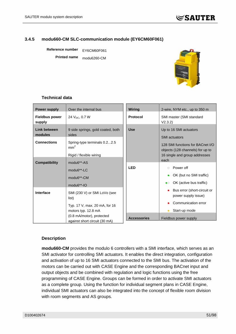
3.4.5 modu660-CM SLC-communication module (EY6CM60F061)
Reference number EY6CM60F061
Printed name modu6260-CM
Technical data
Power supply Over the internal bus
Fieldbus power
supply
24 VDC, 0.7 W
Link between
modules
9 side springs, gold coated, both
sides
Connections Spring-type terminals 0.2...2.5
mm2
Rigid / flexible wiring
Compatibility modu6**-AS
modu6**-LC
modu6**-CM
modu6**-IO
Interface SMI (230 V) or SMI LoVo (see
list)
Typ. 17 V, max. 20 mA, for 16
motors typ. 12.8 mA
(0.8 mA/motor), protected
against short circuit (30 mA)
Wiring 2-wire, NYM etc., up to 350 m
Protocol SMI master (SMI standard
V2.3.2)
Use Up to 16 SMI actuators
SMI actuators
128 SMI functions for BACnet I/O
objects (128 channels) for up to
16 single and group addresses
each
LED ◌ Power off
● OK (but no SMI traffic)
●◌ OK (active bus traffic)
● Bus error (short-circuit or
power supply issue)
● Communication error
● Start-up mode
Accessories Fieldbus power supply
Description
modu660-CM provides the modulo 6 controllers with a SMI interface, which serves as an
SMI activator for controlling SMI actuators. It enables the direct integration, configuration
and activation of up to 16 SMI actuators connected to the SMI bus. The activation of the
motors can be carried out with CASE Engine and the corresponding BACnet input and
output objects and be combined with regulation and logic functions using the free
programming of CASE Engine. Groups can be formed in order to activate SMI actuators
as a complete group. Using the function for individual segment plans in CASE Engine,
individual SMI actuators can also be integrated into the concept of flexible room division
with room segments and AS groups.
SAUTER modulo system description
D100402674
52/98
The SMI-easyMonitor (download from www.standard-motor-interface.com) is required for
the commissioning and addressing of the SMI actuators. The tool can use a virtual serial
port to access the SMI bus directly via modu6** controllers (tunnelling) and perform the
addressing of the SMI actuators. No USB-SMI converter is required. The configuration of
the end stops of the individual hangings (window blinds, roller shutters, etc) must be
carried out on site directly on the motors using the individual setting tools to be obtained
from the respective manufacturer. The commissioning via SMI-easyMonitor should be
carried out first. The parallel operation of SMI-easyMonitor and the modulo 6 program for
activating SMI motors is not supported. The adjustment of the position and angle of the
hangings (e.g. window blinds/slats) can be carried out individually using CASE Engine
Plan. All SMI actuators can be used as with ecos-SMI (see ecos-SMI compatibility list
D100370158).
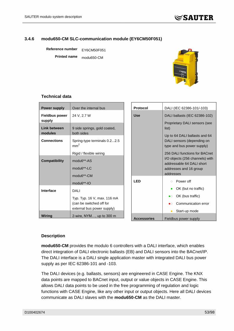
SAUTER modulo system description
D100402674
53/98
3.4.6 modu650-CM SLC-communication module (EY6CM50F051)
Reference number EY6CM50F051
Printed name modu650-CM
Technical data
Power supply Over the internal bus
Fieldbus power
supply
24 V, 2.7 W
Link between
modules
9 side springs, gold coated,
both sides
Connections Spring-type terminals 0.2...2.5
mm2
Rigid / flexible wiring
Compatibility modu6**-AS
modu6**-LC
modu6**-CM
modu6**-IO
Interface DALI
Typ. Typ. 16 V, max. 116 mA
(can be switched off for
external bus power supply)
Wiring 2-wire, NYM…, up to 300 m
Protocol DALI (IEC 62386-101/-103)
Use DALI ballasts (IEC 62386-102)
Proprietary DALI sensors (see
list)
Up to 64 DALI ballasts and 64
DALI sensors (depending on
type and bus power supply)
256 DALI functions for BACnet
I/O objects (256 channels) with
addressable 64 DALI short
addresses and 16 group
addresses
LED ◌ Power off
● OK (but no traffic)
●◌ OK (bus traffic)
●◌ Communication error
● Start-up mode
Accessories Fieldbus power supply
Description
modu650-CM provides the modulo 6 controllers with a DALI interface, which enables
direct integration of DALI electronic ballasts (EB) and DALI sensors into the BACnet/IP.
The DALI interface is a DALI single application master with integrated DALI bus power
supply as per IEC 62386-101 and -103.
The DALI devices (e.g. ballasts, sensors) are engineered in CASE Engine. The KNX
data points are mapped to BACnet input, output or value objects in CASE Engine. This
allows DALI data points to be used in the free programming of regulation and logic
functions with CASE Engine, like any other input or output objects. Here all DALI devices
communicate as DALI slaves with the modu650-CM as the DALI master.
SAUTER modulo system description
D100402674
54/98
For commissioning, the engineered DALI data points, with the defined DALI short
addresses and DALI group addresses, are exported from CASE Engine and are
imported with the integrated, web-based DALI commissioning page. Thus, the
engineered DALI addresses with their corresponding installation location can be
assigned to the devices actually installed. The related DALI parameters are also loaded
onto the DALI devices in this way.
The DALI network is thus a local field bus for the lighting within the rooms or room
segments that are regulated by a modulo 6 controller via a modu650-CM. This means
that many DALI bus segments can exist in a building. For simple commissioning and
maintenance, all DALI segments can be directly accessed from the shared BACnet/IP
(Ethernet). The work station with CASE Engine and a web browser for the web server
commissioning tool is connected with the Ethernet network and the corresponding IP
address of the modulo 6 controller. This means that it is not necessary to be locally
connected to every individual DALI segment.
The modu650-CM with the DALI module has an integrated DALI bus power supply (up
to 116 mA). The internal DALI bus power supply can also be switched off via CASE or
DALI-COT in order to use an external DALI power supply module. Note that all power
supplies connected to the bus must not supply a combined total of more than 250 mA.
The internal DALI bus power supply has short-circuit monitoring as per IEC 62386-101
(section 6.6.2). Therefore, when operating simultaneously with an internal and an
external power supply, the external power supply must not have a short-circuit switch-off.
All DALI ballast devices according to IEC 62386-102 can be used with the ecos DALI.
The following must be considered:
Supported DALI functions (see table)
No support for DALI ballast additional functions as per IEC 62386-2xx
Design of the DALI bus power supply
Number of DALI addresses and functions to be used
Consideration of the bus bandwidth via optimum settings for the DALI master
functions (query intervals, priority etc.)
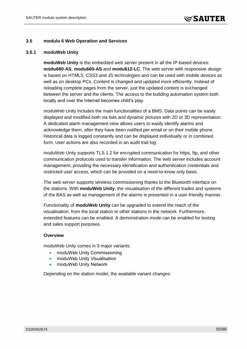
SAUTER modulo system description
D100402674
55/98
3.5 modulo 6 Web Operation and Services
3.5.1 moduWeb Unity
moduWeb Unity is the embedded web server present in all the IP-based devices:
modu680-AS, modu660-AS and modu612-LC. The web server with responsive design
is based on HTML5, CSS3 and JS technologies and can be used with mobile devices as
well as on desktop PCs. Content is changed and updated more efficiently. Instead of
reloading complete pages from the server, just the updated content is exchanged
between the server and the clients. The access to the building automation system both
locally and over the Internet becomes child’s play.
moduWeb Unity includes the main functionalities of a BMS. Data points can be easily
displayed and modified both via lists and dynamic pictures with 2D or 3D representation.
A dedicated alarm management view allows users to easily identify alarms and
acknowledge them, after they have been notified per email or on their mobile phone.
Historical data is logged constantly and can be displayed individually or in combined
form. User actions are also recorded in an audit trail log.
moduWeb Unity supports TLS 1.2 for encrypted communication for https, ftp, and other
communication protocols used to transfer information. The web server includes account
management, providing the necessary identification and authentication credentials and
restricted user access, which can be provided on a need-to-know only basis.
The web server supports wireless commissioning thanks to the Bluetooth interface on
the stations. With moduWeb Unity, the visualisation of the different trades and systems
of the BAS as well as management of the alarms is presented in a user-friendly manner.
Functionality of moduWeb Unity can be upgraded to extend the reach of the
visualisation, from the local station to other stations in the network. Furthermore,
extended features can be enabled. A demonstration mode can be enabled for testing
and sales support purposes.
Overview
moduWeb Unity comes in 3 major variants:
moduWeb Unity Commissioning
moduWeb Unity Visualisation
moduWeb Unity Network
Depending on the station model, the available variant changes:
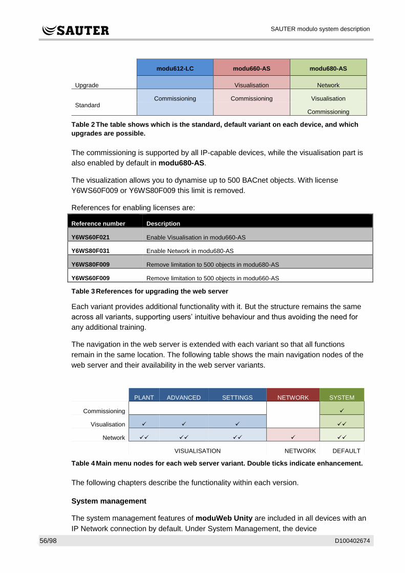
SAUTER modulo system description
D100402674
56/98
modu612-LC modu660-AS modu680-AS
Upgrade Visualisation Network
Standard Commissioning Commissioning Visualisation
Commissioning
Table 2 The table shows which is the standard, default variant on each device, and which
upgrades are possible.
The commissioning is supported by all IP-capable devices, while the visualisation part is
also enabled by default in modu680-AS.
The visualization allows you to dynamise up to 500 BACnet objects. With license
Y6WS60F009 or Y6WS80F009 this limit is removed.
References for enabling licenses are:
Reference number Description
Y6WS60F021 Enable Visualisation in modu660-AS
Y6WS80F031 Enable Network in modu680-AS
Y6WS80F009 Remove limitation to 500 objects in modu680-AS
Y6WS60F009 Remove limitation to 500 objects in modu660-AS
Table 3 References for upgrading the web server
Each variant provides additional functionality with it. But the structure remains the same
across all variants, supporting users’ intuitive behaviour and thus avoiding the need for
any additional training.
The navigation in the web server is extended with each variant so that all functions
remain in the same location. The following table shows the main navigation nodes of the
web server and their availability in the web server variants.
PLANT ADVANCED SETTINGS NETWORK SYSTEM
Commissioning
Visualisation
Network
VISUALISATION NETWORK DEFAULT
Table 4 Main menu nodes for each web server variant. Double ticks indicate enhancement.
The following chapters describe the functionality within each version.
System management
The system management features of moduWeb Unity are included in all devices with an
IP Network connection by default. Under System Management, the device
SAUTER modulo system description
D100402674
57/98
commissioning is made possible directly via the web user interface, without any
additional tooling. Attached modules can also be detected and commissioned. No project
is needed at this stage. Also important is the possibility to upgrade the web server
functionality with license activation, as long as the device allows it.
The following list provides an overview of features under the System management menu:
User Management
Management of user accounts, user role, access rights and notification methods
(mail, phone)
Network and security settings
All related to IP settings, servers, proxies and certificates
General device settings
Other devices settings like time and date.
Commissioning
Commissioning of device and attached modules
License Management
Upgrading web server functionality, when supported
moduWeb Unity Visualisation
With moduWeb Unity visualization functions, the application can be represented in 2D
or 3D images. Die umfangreichen grafischen Möglichkeiten ermöglichen die Realisierung
dynamischer Bilder, die den effektiven Status darstellen. Users can interact via this user
interface and change values like set-points or switching lights on or off. The information
can be structured to ease reading and obtain quick access to the relevant information.
Changes made by any user are logged in an audit trail.
Dedicated views and optimised wizards allow the most important functions to be easily
managed. The system and application alarms have dedicated views, for the current
alarms and for the alarms history. The user can select the chronological or structured
view. The current alarm status and messages are displayed on the list and alarms can
be acknowledged. Schedules and Calendars also have dedicated views for quick
identification of the operating status.
The visualisation mode is standard in modu680-AS and can be activated on modu660-
AS, where it is also available in demonstration mode for a limited time.
Alarm management
Displays current alarms and alarms history. Acknowledges alarms and exports
alarm list
Alarm notification
Sends alarms to selected users’ email or phone account
Plant visualisation and dynamization
Structured navigation across dynamic pictures of the plant. Visualisation and
manipulation of object and value lists
Charts
Graphical representation of values history
SAUTER modulo system description
D100402674
58/98
Audit trail
List of user operations. Export list
Advanced functions
Configuring Schedules & Calendars, Trend Logs or simple Commands
Project settings
moduWeb Unity Network
moduWeb Unity can be extended on modu680-AS to include other modulo 6 and
BACnet devices in the network. Thus, a single point of access is provided to the
moduWeb Unity visualisation, alarming and notification functionality. Additionally, this
extension also allows a centralised management of the modulo 6 devices which also
supports moduWeb Unity. It is possible to share and manage user credentials and
rights for the other devices.
Common alarm list
Alarm consolidation in one list for all registered devices
Common visualisation
Visualisation solution including local and remote devices
Remote device management
Network scan and device embedding
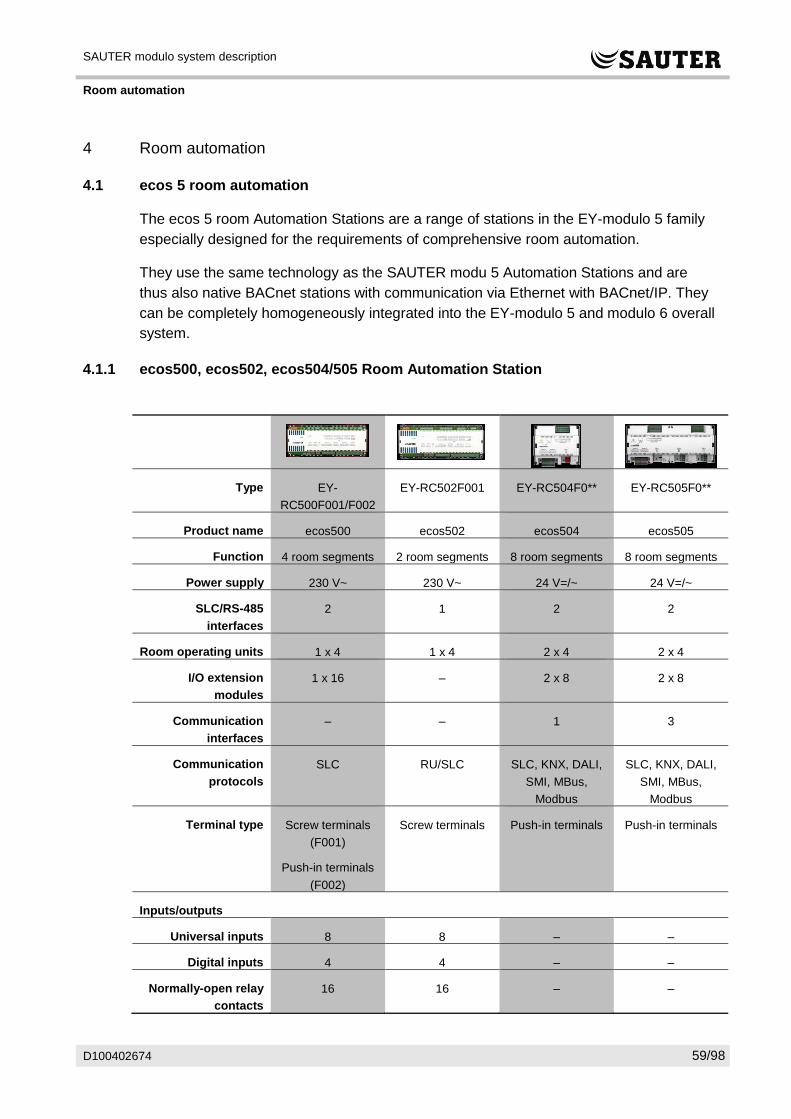
SAUTER modulo system description
Room automation
D100402674
59/98
4 Room automation
4.1 ecos 5 room automation
The ecos 5 room Automation Stations are a range of stations in the EY-modulo 5 family
especially designed for the requirements of comprehensive room automation.
They use the same technology as the SAUTER modu 5 Automation Stations and are
thus also native BACnet stations with communication via Ethernet with BACnet/IP. They
can be completely homogeneously integrated into the EY-modulo 5 and modulo 6 overall
system.
4.1.1 ecos500, ecos502, ecos504/505 Room Automation Station
Type EY-
RC500F001/F002
EY-RC502F001 EY-RC504F0** EY-RC505F0**
Product name ecos500 ecos502 ecos504 ecos505
Function 4 room segments 2 room segments 8 room segments 8 room segments
Power supply 230 V~ 230 V~ 24 V=/~ 24 V=/~
SLC/RS-485
interfaces
2 1 2 2
Room operating units 1 x 4 1 x 4 2 x 4 2 x 4
I/O extension
modules
1 x 16 – 2 x 8 2 x 8
Communication
interfaces
– – 1 3
Communication
protocols
SLC RU/SLC SLC, KNX, DALI,
SMI, MBus,
Modbus
SLC, KNX, DALI,
SMI, MBus,
Modbus
Terminal type Screw terminals
(F001)
Push-in terminals
(F002)
Screw terminals Push-in terminals Push-in terminals
Inputs/outputs
Universal inputs 8 8 – –
Digital inputs 4 4 – –
Normally-open relay
contacts
16 16 – –
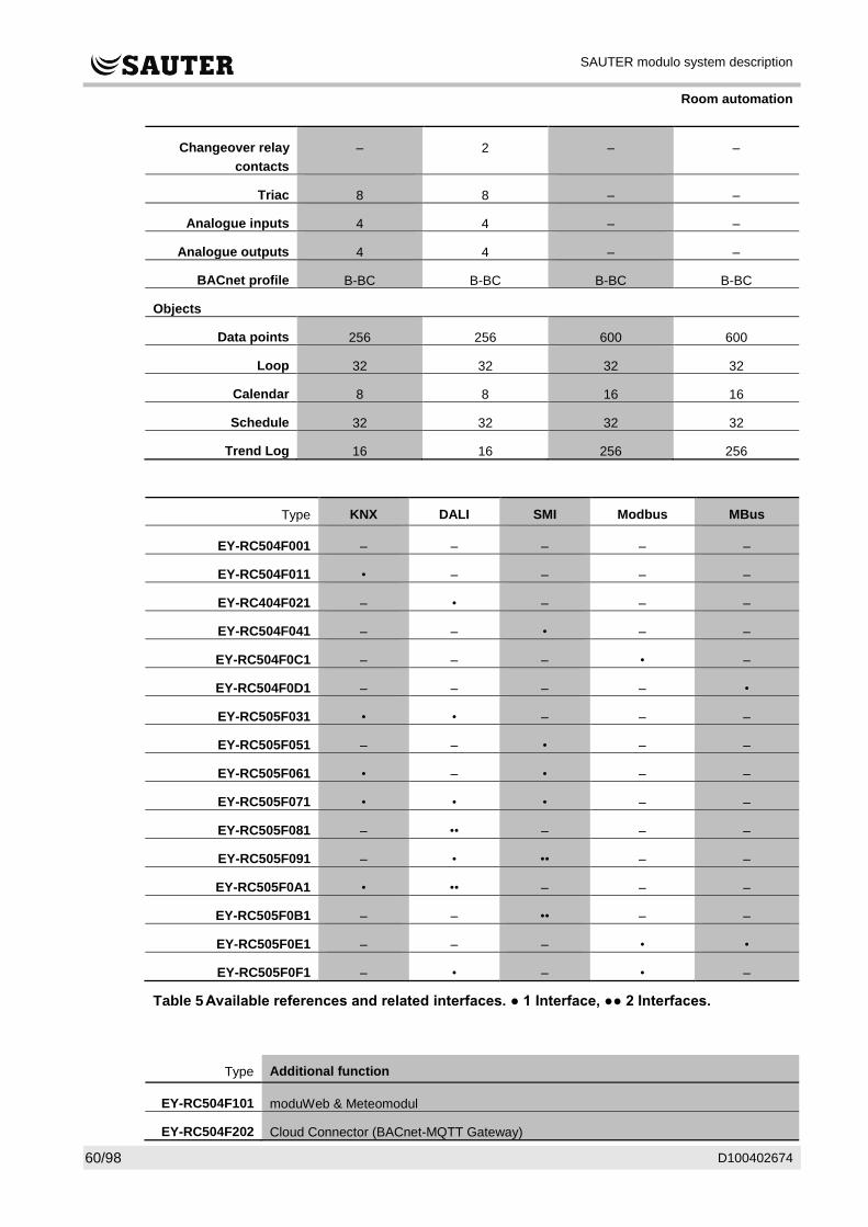
SAUTER modulo system description
Room automation
D100402674
60/98
Changeover relay
contacts
– 2 – –
Triac 8 8 – –
Analogue inputs 4 4 – –
Analogue outputs 4 4 – –
BACnet profile B-BC B-BC B-BC B-BC
Objects
Data points 256 256 600 600
Loop 32 32 32 32
Calendar 8 8 16 16
Schedule 32 32 32 32
Trend Log 16 16 256 256
Type KNX DALI SMI Modbus MBus
EY-RC504F001 – – – – –
EY-RC504F011 • – – – –
EY-RC404F021 – • – – –
EY-RC504F041 – – • – –
EY-RC504F0C1 – – – • –
EY-RC504F0D1 – – – – •
EY-RC505F031 • • – – –
EY-RC505F051 – – • – –
EY-RC505F061 • – • – –
EY-RC505F071 • • • – –
EY-RC505F081 – •• – – –
EY-RC505F091 – • •• – –
EY-RC505F0A1 • •• – – –
EY-RC505F0B1 – – •• – –
EY-RC505F0E1 – – – • •
EY-RC505F0F1 – • – • –
Table 5 Available references and related interfaces. ● 1 Interface, ●● 2 Interfaces.
Type Additional function
EY-RC504F101 moduWeb & Meteomodul
EY-RC504F202 Cloud Connector (BACnet-MQTT Gateway)

SAUTER modulo system description
Room automation
D100402674
61/98
Table 6 Functions additionally activated in EY-RC504
The ecos 5 room Automation Stations are designed for temperature regulation and for
controlling lights, blinds etc. in individually regulated rooms.
The ecos500 and ecos502 provide all inputs and outputs for room automation compactly
and directly on the device.
The ecos502 is designed for the control of 2 rooms or 2 segments (i.e. the I/O mix of
the ecos502 is adapted for 2 rooms or 2 segments); the ecos500 is designed for 4
rooms or 4 segments.
On the ecos500 and ecos502 stations, 8 of the 12 inputs are universal inputs (UI) that
can be parameterised freely as temperature, voltage or current measurement inputs or
binary inputs. This offers the option of optimum use of the I/O mix of the station.
On the ecos500, the I/O mix can also be expanded for more complex applications using
decentrally mountable ecoLink input/output modules. The ecoLink modules are
connected to the ecos 5 in bus form (RS-485 interface) and can be located up to 500 m
away from the station (See section 4.2: Remote ecoLink I/O modules)
ecos504 and ecos505 are modular stations and have neither inputs nor outputs. The
inputs/outputs are modular with the remote ecoLink I/O modules and the integrated
communication interfaces for DALI, KNX, SMI, MBus and Modbus. ecos504 and
ecos505 are designed for controlling up to 8 rooms or room segments.
In addition to the control and regulation functions, comprehensive time and calendar
functions are also available. Up to 32 BACnet time programme objects (Schedule) and
8 BACnet Calendar objects (Calendar) can be created in the Automation Station.
4 or 2 x 4 connectable room operating units of type ecoUnit 3 (EYRU3F***) or ecoUnit 1
(EY-RU1F***) are used for room-temperature measurement and allow individual
adjustment of the room climate to the user’s requirements (see section ecoUnit room
operating units)
Powerful function modules in the ecos 5 stations enable energy-optimised room
control. The following also aid the optimisation of the energy consumption of the
controlled rooms: presence function, window contact monitoring, demand-controlled
switching of fan speeds, control of lighting and window blinds, and time-dependent
setpoint specification.
The complete user program and the different parameterisations (BACnet objects, etc.)
are created using CASE Suite. Up to 256 or 600 BACnet data points incl. hardware
inputs and outputs can be used. For programming/parameterisation in CASE Suite,
comprehensive regulating libraries are available.
The user program and the changed data (e.g. changed by the BACnet client) are stored
persistently in the flash memory. An insertable lithium button-cell battery ensures that
the RTC for time programmes (Scheduler/Calendar) and data such as meters, e.g.
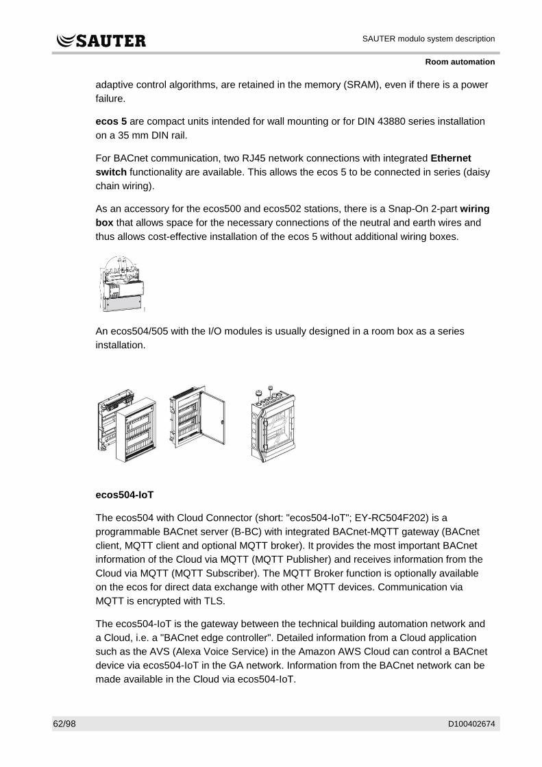
SAUTER modulo system description
Room automation
D100402674
62/98
adaptive control algorithms, are retained in the memory (SRAM), even if there is a power
failure.
ecos 5 are compact units intended for wall mounting or for DIN 43880 series installation
on a 35 mm DIN rail.
For BACnet communication, two RJ45 network connections with integrated Ethernet
switch functionality are available. This allows the ecos 5 to be connected in series (daisy
chain wiring).
As an accessory for the ecos500 and ecos502 stations, there is a Snap-On 2-part wiring
box that allows space for the necessary connections of the neutral and earth wires and
thus allows cost-effective installation of the ecos 5 without additional wiring boxes.
An ecos504/505 with the I/O modules is usually designed in a room box as a series
installation.
ecos504-IoT
The ecos504 with Cloud Connector (short: "ecos504-IoT"; EY-RC504F202) is a
programmable BACnet server (B-BC) with integrated BACnet-MQTT gateway (BACnet
client, MQTT client and optional MQTT broker). It provides the most important BACnet
information of the Cloud via MQTT (MQTT Publisher) and receives information from the
Cloud via MQTT (MQTT Subscriber). The MQTT Broker function is optionally available
on the ecos for direct data exchange with other MQTT devices. Communication via
MQTT is encrypted with TLS.
The ecos504-IoT is the gateway between the technical building automation network and
a Cloud, i.e. a "BACnet edge controller". Detailed information from a Cloud application
such as the AVS (Alexa Voice Service) in the Amazon AWS Cloud can control a BACnet
device via ecos504-IoT in the GA network. Information from the BACnet network can be
made available in the Cloud via ecos504-IoT.
SAUTER modulo system description
Room automation
D100402674
63/98
The Cloud Connector includes the following additional features with respect to the
standard ecos504.
MQTT Client (MQTT Publisher, MQTT Subscriber)
MQTT protocol V3.1.1 encrypted via TLS 1.2
Optionally connectible MQTT Broker (server)
4.1.2 ecoUnit room operating units
ecoUnits are the room operating units for the ecos 5 room Automation Stations. They
are used to measure the room’s temperature and, depending on the type, have different
operating options and a display with information about the room condition.
The range of room operating units comprises three basic variants:
devices with LED indicator (ecoUnit310...316):
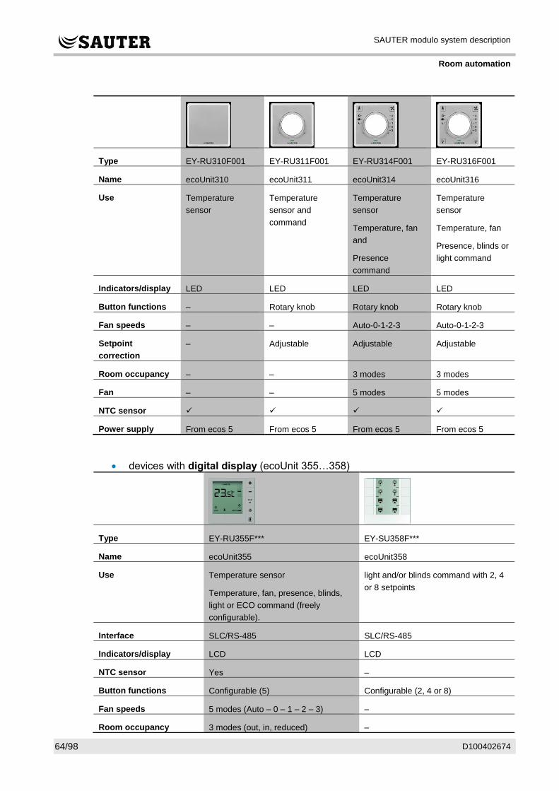
SAUTER modulo system description
Room automation
D100402674
64/98
Type EY-RU310F001 EY-RU311F001 EY-RU314F001 EY-RU316F001
Name ecoUnit310 ecoUnit311 ecoUnit314 ecoUnit316
Use Temperature
sensor
Temperature
sensor and
command
Temperature
sensor
Temperature, fan
and
Presence
command
Temperature
sensor
Temperature, fan
Presence, blinds or
light command
Indicators/display LED LED LED LED
Button functions – Rotary knob Rotary knob Rotary knob
Fan speeds – – Auto-0-1-2-3 Auto-0-1-2-3
Setpoint
correction
– Adjustable Adjustable Adjustable
Room occupancy – – 3 modes 3 modes
Fan – – 5 modes 5 modes
NTC sensor
Power supply From ecos 5 From ecos 5 From ecos 5 From ecos 5
devices with digital display (ecoUnit 355…358)
Type EY-RU355F*** EY-SU358F***
Name ecoUnit355 ecoUnit358
Use Temperature sensor
Temperature, fan, presence, blinds,
light or ECO command (freely
configurable).
light and/or blinds command with 2, 4
or 8 setpoints
Interface SLC/RS-485 SLC/RS-485
Indicators/display LCD LCD
NTC sensor Yes –
Button functions Configurable (5) Configurable (2, 4 or 8)
Fan speeds 5 modes (Auto – 0 – 1 – 2 – 3) –
Room occupancy 3 modes (out, in, reduced) –
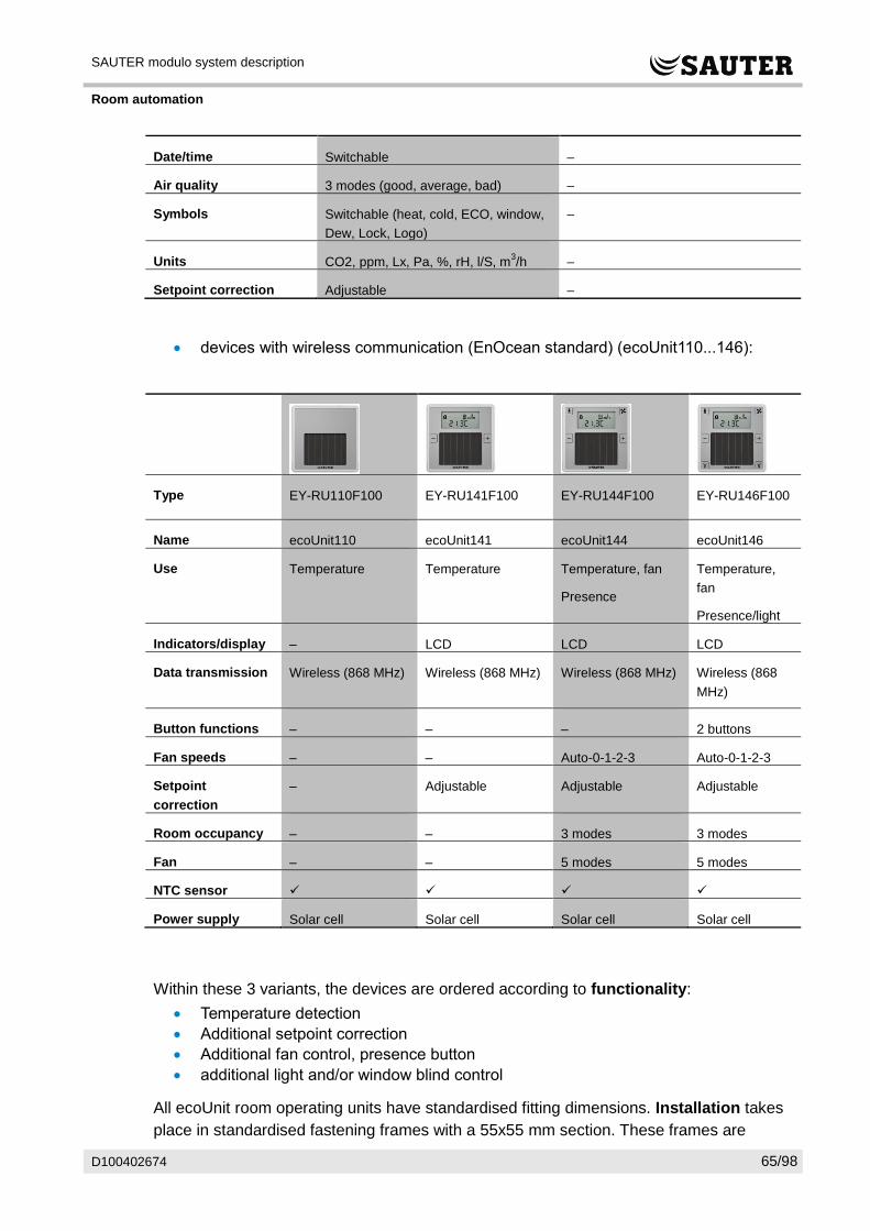
SAUTER modulo system description
Room automation
D100402674
65/98
Date/time Switchable –
Air quality 3 modes (good, average, bad) –
Symbols Switchable (heat, cold, ECO, window,
Dew, Lock, Logo)
–
Units CO2, ppm, Lx, Pa, %, rH, l/S, m3/h –
Setpoint correction Adjustable –
devices with wireless communication (EnOcean standard) (ecoUnit110...146):
Type EY-RU110F100 EY-RU141F100 EY-RU144F100 EY-RU146F100
Name ecoUnit110 ecoUnit141 ecoUnit144 ecoUnit146
Use Temperature Temperature Temperature, fan
Presence
Temperature,
fan
Presence/light
Indicators/display – LCD LCD LCD
Data transmission
Wireless (868 MHz) Wireless (868 MHz) Wireless (868 MHz) Wireless (868
MHz)
Button functions – – – 2 buttons
Fan speeds – – Auto-0-1-2-3 Auto-0-1-2-3
Setpoint
correction
– Adjustable Adjustable Adjustable
Room occupancy – – 3 modes 3 modes
Fan – – 5 modes 5 modes
NTC sensor
Power supply Solar cell Solar cell Solar cell Solar cell
Within these 3 variants, the devices are ordered according to functionality:
Temperature detection
Additional setpoint correction
Additional fan control, presence button
additional light and/or window blind control
All ecoUnit room operating units have standardised fitting dimensions. Installation takes
place in standardised fastening frames with a 55x55 mm section. These frames are
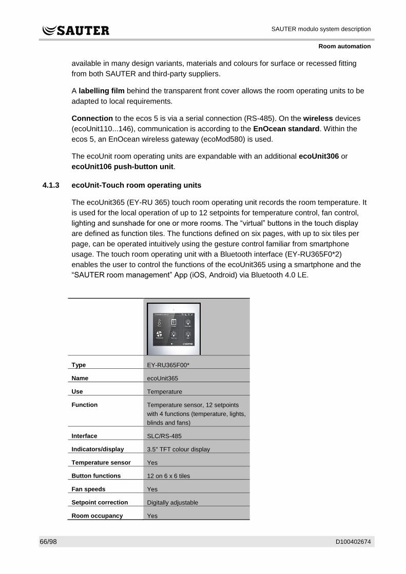
SAUTER modulo system description
Room automation
D100402674
66/98
available in many design variants, materials and colours for surface or recessed fitting
from both SAUTER and third-party suppliers.
A labelling film behind the transparent front cover allows the room operating units to be
adapted to local requirements.
Connection to the ecos 5 is via a serial connection (RS-485). On the wireless devices
(ecoUnit110...146), communication is according to the EnOcean standard. Within the
ecos 5, an EnOcean wireless gateway (ecoMod580) is used.
The ecoUnit room operating units are expandable with an additional ecoUnit306 or
ecoUnit106 push-button unit.
4.1.3 ecoUnit-Touch room operating units
The ecoUnit365 (EY-RU 365) touch room operating unit records the room temperature. It
is used for the local operation of up to 12 setpoints for temperature control, fan control,
lighting and sunshade for one or more rooms. The “virtual” buttons in the touch display
are defined as function tiles. The functions defined on six pages, with up to six tiles per
page, can be operated intuitively using the gesture control familiar from smartphone
usage. The touch room operating unit with a Bluetooth interface (EY-RU365F0*2)
enables the user to control the functions of the ecoUnit365 using a smartphone and the
“SAUTER room management” App (iOS, Android) via Bluetooth 4.0 LE.
Type EY-RU365F00*
Name ecoUnit365
Use Temperature
Function Temperature sensor, 12 setpoints
with 4 functions (temperature, lights,
blinds and fans)
Interface SLC/RS-485
Indicators/display 3.5" TFT colour display
Temperature sensor Yes
Button functions 12 on 6 x 6 tiles
Fan speeds Yes
Setpoint correction Digitally adjustable
Room occupancy Yes
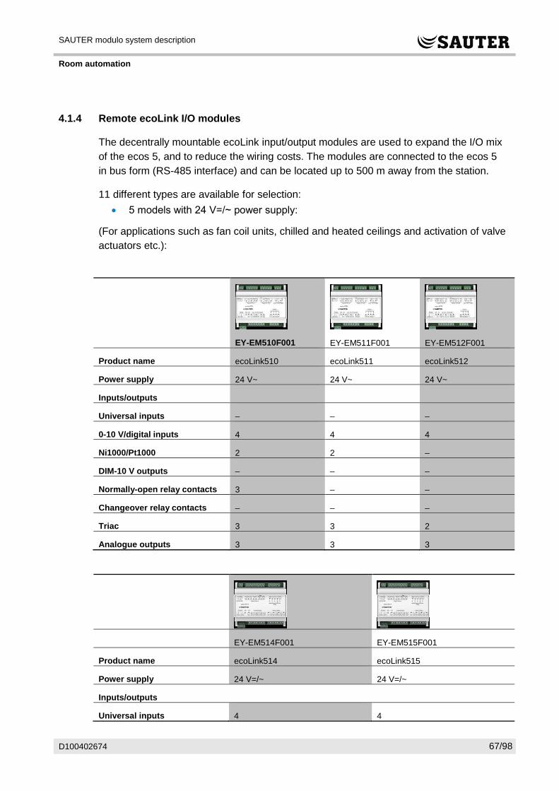
SAUTER modulo system description
Room automation
D100402674
67/98
4.1.4 Remote ecoLink I/O modules
The decentrally mountable ecoLink input/output modules are used to expand the I/O mix
of the ecos 5, and to reduce the wiring costs. The modules are connected to the ecos 5
in bus form (RS-485 interface) and can be located up to 500 m away from the station.
11 different types are available for selection:
5 models with 24 V=/~ power supply:
(For applications such as fan coil units, chilled and heated ceilings and activation of valve
actuators etc.):
EY-EM510F001
EY-EM511F001
EY-EM512F001
Product name ecoLink510 ecoLink511 ecoLink512
Power supply 24 V~ 24 V~ 24 V~
Inputs/outputs
Universal inputs – – –
0-10 V/digital inputs 4 4 4
Ni1000/Pt1000 2 2 –
DIM-10 V outputs – – –
Normally-open relay contacts 3 – –
Changeover relay contacts – – –
Triac 3 3 2
Analogue outputs 3 3 3
EY-EM514F001 EY-EM515F001
Product name ecoLink514 ecoLink515
Power supply 24 V=/~ 24 V=/~
Inputs/outputs
Universal inputs 4 4
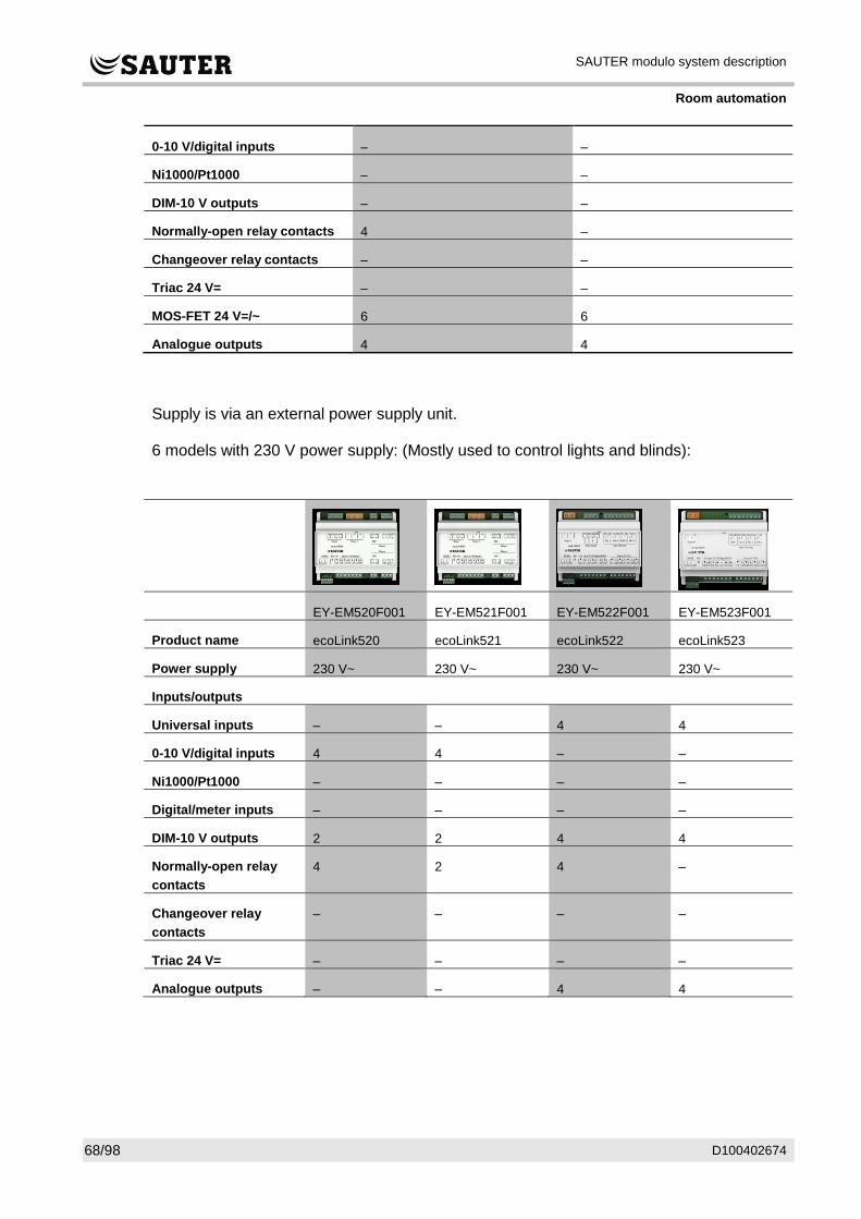
SAUTER modulo system description
Room automation
D100402674
68/98
0-10 V/digital inputs – –
Ni1000/Pt1000 – –
DIM-10 V outputs – –
Normally-open relay contacts 4 –
Changeover relay contacts – –
Triac 24 V= – –
MOS-FET 24 V=/~ 6 6
Analogue outputs 4 4
Supply is via an external power supply unit.
6 models with 230 V power supply: (Mostly used to control lights and blinds):
EY-EM520F001 EY-EM521F001 EY-EM522F001 EY-EM523F001
Product name ecoLink520 ecoLink521 ecoLink522 ecoLink523
Power supply 230 V~ 230 V~ 230 V~ 230 V~
Inputs/outputs
Universal inputs – – 4 4
0-10 V/digital inputs 4 4 – –
Ni1000/Pt1000 – – – –
Digital/meter inputs – – – –
DIM-10 V outputs 2 2 4 4
Normally-open relay
contacts
4 2 4 –
Changeover relay
contacts
– – – –
Triac 24 V= – – – –
Analogue outputs – – 4 4
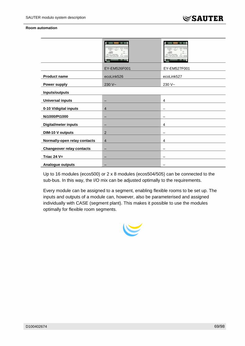
SAUTER modulo system description
Room automation
D100402674
69/98
EY-EM526F001 EY-EM527F001
Product name ecoLink526 ecoLink527
Power supply 230 V~ 230 V~
Inputs/outputs
Universal inputs – 4
0-10 V/digital inputs 4 –
Ni1000/Pt1000 – –
Digital/meter inputs – 4
DIM-10 V outputs 2 –
Normally-open relay contacts 4 4
Changeover relay contacts – –
Triac 24 V= – –
Analogue outputs – –
Up to 16 modules (ecos500) or 2 x 8 modules (ecos504/505) can be connected to the
sub-bus. In this way, the I/O mix can be adjusted optimally to the requirements.
Every module can be assigned to a segment, enabling flexible rooms to be set up. The
inputs and outputs of a module can, however, also be parameterised and assigned
individually with CASE (segment plant). This makes it possible to use the modules
optimally for flexible room segments.
SAUTER modulo system description
Building Management and Control
D100402674
70/98
5 Building Management and Control
5.1 SAUTER Vision Center – central building management and visualisation
SAUTER Vision Center is a web-based building management solution in the HTML5
standard. It allows platform-independent operation on smartphones, tablets or desktop
PCs without setting up inconvenient plug-ins. This means that personnel always have
access to the new, individually configurable dashboards as a central information
interface for system operation, energy consumption, associated alarms and key figures
and lots more. Other detailed information such as alarm reports, interactive object lists,
diagrams and reports can also be accessed directly.
Projects of all sizes
SAUTER Vision Center is suitable for both larger single buildings and entire real estate
parks or decentralised premises. Typical areas of use are office complexes, business
parks, college and industrial campuses, airports, railway stations, hospitals or
internationally distributed branch networks. The modular concept allows the software to
be extended precisely to meet the customer requirements of every installation.
SAUTER Vision Center sends alarms directly via e-mail or SMS to mobile phones
according to the responsibilities assigned. With its many user-defined settings and
dashboards that can be customised with drag & drop, SAUTER Vision Center
guarantees maximum user convenience. This enables complete concentration on the
monitoring and evaluation of the installations, as well as their optimum operation, and
contributes to efficient, sustainable building and energy management.
Building, energy and maintenance management
The functionalities of SAUTER Vision Center go far beyond the usual tasks of a building
management system, such as the visualisation, monitoring, logging and controlling of
installations: With its own energy management module the solution supports system
operators efficiently during energy and maintenance management. Users can map
consumption values and KPIs on their own charts and dashboards and check current
values hourly if required. The different views are organised in building, energy or user-
defined navigation structures and can be selected directly.
During service planning, the maintenance management also supports service tasks and
creates task orders based on the building management system data that can be
assigned and monitored by the service manager.
Communication protocols
With the certified BACnet client in SAUTER Vision Center and the OPC UA client,
practically all devices and information sources in the building can be connected.
SAUTER modulo system description
Building Management and Control
D100402674
71/98
The standardised protocols enable both SAUTER and non-SAUTER devices to be
incorporated. Vision Center has an OPC UA / DA gateway for the integration of older
OPC DA servers. SAUTER Vision Center additionally offers operation as an OPC UA
server to enable all building management information to be integrated for other
applications via an OPC UA client.
This range of integration options with many different protocols such as M-Bus, Modbus,
LON and system-specific OPC servers, as well as BACnet, enables the highest level of
flexibility for controlling various building parts and system generations using the building
management software. This enables the plannable, successive migration of building
parts and premises to the central SAUTER Vision Center building management.
Naturally, SAUTER Vision Center also supports connection via the SAUTER novaNet
communication protocol, so that even older installations can benefit from the innovations
of this state-of-the-art building management software.
SAUTER Vision Center also has a REST API for connecting applications that use
building management information for their own purposes. Thus, SAUTER Vision Center
can be incorporated into the processes and application structures of companies as a
central component.
Highlights:
For projects of all sizes:
SVC is suitable for buildings of all types – from single buildings to multi-site premises and
big projects, and from administration buildings to research labs.
Easy to operate for all users:
With personalised views and navigations such as dashboards, lists etc., each user can
put together the information relevant to their range of tasks and view all of it at the same
time.
Scenario Manager for very simple operation:
The Scenario Manager enables scenarios to be defined and assigned with a few clicks in
SVC, providing even more flexible system management.
Access regardless of location:
SVC provides information on all conventional end devices such as desktops, laptops,
tablets, smartphones and smart watches.
Centralised building, energy and maintenance management:
SVC has a modular structure and is freely scalable. The integration of specialised
auxiliary modules enables it to be used for different tasks in the building.
SAUTER modulo system description
Building Management and Control
D100402674
72/98
Room management:
SVC supports the segment concept of SAUTER room automation allowing room
segment assignments to be immediately adjusted to the customer’s needs via the
building management without any engineering work. For example, the adjustment of
office sizes when tenants change or particular controlling of rooms when empty for the
purpose of energy optimisation.
Precise insights for smart building management:
SVC creates user-specific evaluations for owners, managers and users and supports
them in optimising building operation.
Security and compliance:
With special functions for traceability and gap-free data acquisition, SVC provides
increased security for business-critical systems and processes.
Investment security thanks to standards and expandability:
SVC is BACnet-certified, also uses OPC UA and supports the connection of SAUTER
novaNet for a heterogeneous system landscape. This is what we mean by successive
extension and gentle migration for ultimate investment security.
5.2 SAUTER Engineering Suite
The SAUTER CASE Suite engineering software with various modules for
SAUTER devices and software packages is optimised for use with SVC. In particular,
CASE Vision can be used to engineer all SAUTER Vision Center projects and the
visualisation libraries can be used to set them up efficiently and uniformly. In addition,
Vision Center Studio offers a local engineering tool for direct installation on the SVC
server in order to make small, quick changes or extensions online.
For an extended description of the engineering toolchain, read the chapter on Integrated
CASE Suite service.
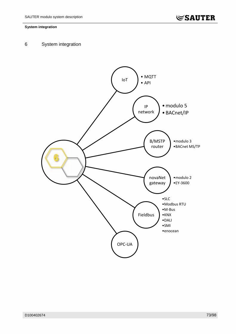
SAUTER modulo system description
System integration
D100402674
73/98
6 System integration
IoT • MQTT
• API
IP network
•modulo 5
•BACnet/IP
B/MSTP router
•modulo 3
•BACnet MS/TP
novaNet gateway
•modulo 2
•EY-3600
Fieldbus
•SLC
•Modbus RTU
•M-Bus
•KNX
•DALI
•SMI
•enocean
OPC-UA
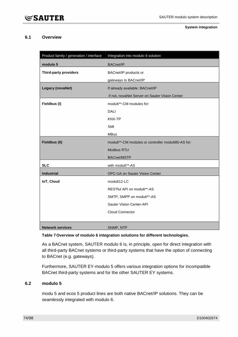
SAUTER modulo system description
System integration
D100402674
74/98
6.1 Overview
Product family / generation / interface Integration into modulo 6 solution
modulo 5 BACnet/IP
Third-party providers BACnet/IP products or
gateways to BACnet/IP
Legacy (novaNet) If already available: BACnet/IP
if not, novaNet Server on Sauter Vision Center
Fieldbus (I) modu6**-CM modules for:
DALI
KNX-TP
SMI
MBus
Fieldbus (II) modu6**-CM modules or controller modu680-AS for:
Modbus RTU
BACnet/MSTP
SLC with modu6**-AS
Industrial OPC-UA on Sauter Vision Center
IoT, Cloud modu612-LC
RESTful API on modu6**-AS
SMTP, SMPP on modu6**-AS
Sauter Vision Center-API
Cloud Connector
Network services SNMP, NTP
Table 7 Overview of modulo 6 integration solutions for different technologies.
As a BACnet system, SAUTER modulo 6 is, in principle, open for direct integration with
all third-party BACnet systems or third-party systems that have the option of connecting
to BACnet (e.g. gateways).
Furthermore, SAUTER EY-modulo 5 offers various integration options for incompatible
BACnet third-party systems and for the other SAUTER EY systems.
6.2 modulo 5
modu 5 and ecos 5 product lines are both native BACnet/IP solutions. They can be
seamlessly integrated with modulo 6.
SAUTER modulo system description
System integration
D100402674
75/98
6.3 Legacy (novaNet)
novaNet based installations can be integrated following different strategies:
Using further legacy products that support BACnet/IP o EY-AM300, EYK300
Using further legacy products that can communicate with a PC running SAUTER Vision Center
o EY-BU291, EY-BU292 o novaNet Server
6.4 Fieldbus, SLC
Modulo 6 Building Controllers support the SLC protocol both on-board and with fieldbus
modules. Modbus RTU and BACnet/MSTP are also supported by modulo 6 stations both
on-board and with fieldbus modules. Other fieldbus protocols are supported with
dedicated fieldbus modules. See the chapter on modulo 6 Communication Modules for
details.
6.5 Industrial
6.6 SAUTER Vision Center allows the integration of third-party systems with the OPC
UA industrial protocol IoT and the Cloud
modulo 6 provides a RESTful API for integration of Cloud Solutions. As soon as the
standard is released, BACnet/SC (Secure Communication) will also be supported.
modulo 6 Automation Stations use MQTT as the protocol to link the modu612-LC. As
they are also MQTT brokers, they can integrate 3rd party devices like sensors using this
same protocol.
The ecos504-IoT (EY-RC504F202) also supports MQTT for IoT and cloud integration.
6.7 Network services
modulo 6 supports different IP Network related services.
Meteomodul This service is supplied by Sauter and provides a 3-day weather forecast for a given
location to the Automation Station.
Hail warning This service, available only in Switzerland, provides up-to-date information on the risk of
hail at a given location to protect assets.
e-mail client
SMTP
moduWeb Unity supports the configuration of an email client to send alarm notifications to
registered users.
SMS via
gateway
moduWeb Unity supports the configuration of an email to SMS gateway to send alarm
notifications to registered users.
SMPP moduWeb Unity supports the configuration of an SMS client to send alarm notifications to
registered users.
SAUTER modulo system description
System integration
D100402674
76/98
NTP moduWeb Unity supports the configuration of an NTP client to synchronise time over the
Internet.
SNMP moduWeb Unity supports the configuration of an SNMP agent for the IT network
management.
Table 8 Network services that can be optionally supported by some modulo 6 stations.
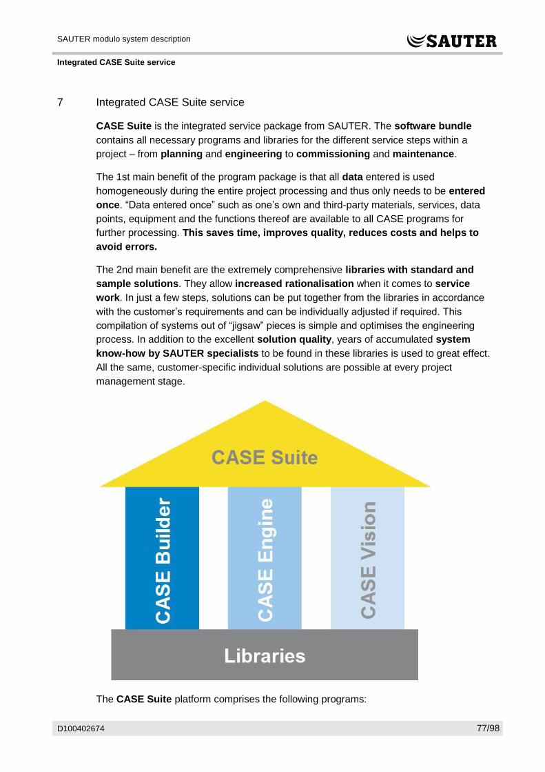
SAUTER modulo system description
Integrated CASE Suite service
D100402674
77/98
7 Integrated CASE Suite service
CASE Suite is the integrated service package from SAUTER. The software bundle
contains all necessary programs and libraries for the different service steps within a
project – from planning and engineering to commissioning and maintenance.
The 1st main benefit of the program package is that all data entered is used
homogeneously during the entire project processing and thus only needs to be entered
once. “Data entered once” such as one’s own and third-party materials, services, data
points, equipment and the functions thereof are available to all CASE programs for
further processing. This saves time, improves quality, reduces costs and helps to
avoid errors.
The 2nd main benefit are the extremely comprehensive libraries with standard and
sample solutions. They allow increased rationalisation when it comes to service
work. In just a few steps, solutions can be put together from the libraries in accordance
with the customer’s requirements and can be individually adjusted if required. This
compilation of systems out of “jigsaw” pieces is simple and optimises the engineering
process. In addition to the excellent solution quality, years of accumulated system
know-how by SAUTER specialists to be found in these libraries is used to great effect.
All the same, customer-specific individual solutions are possible at every project
management stage.
The CASE Suite platform comprises the following programs:
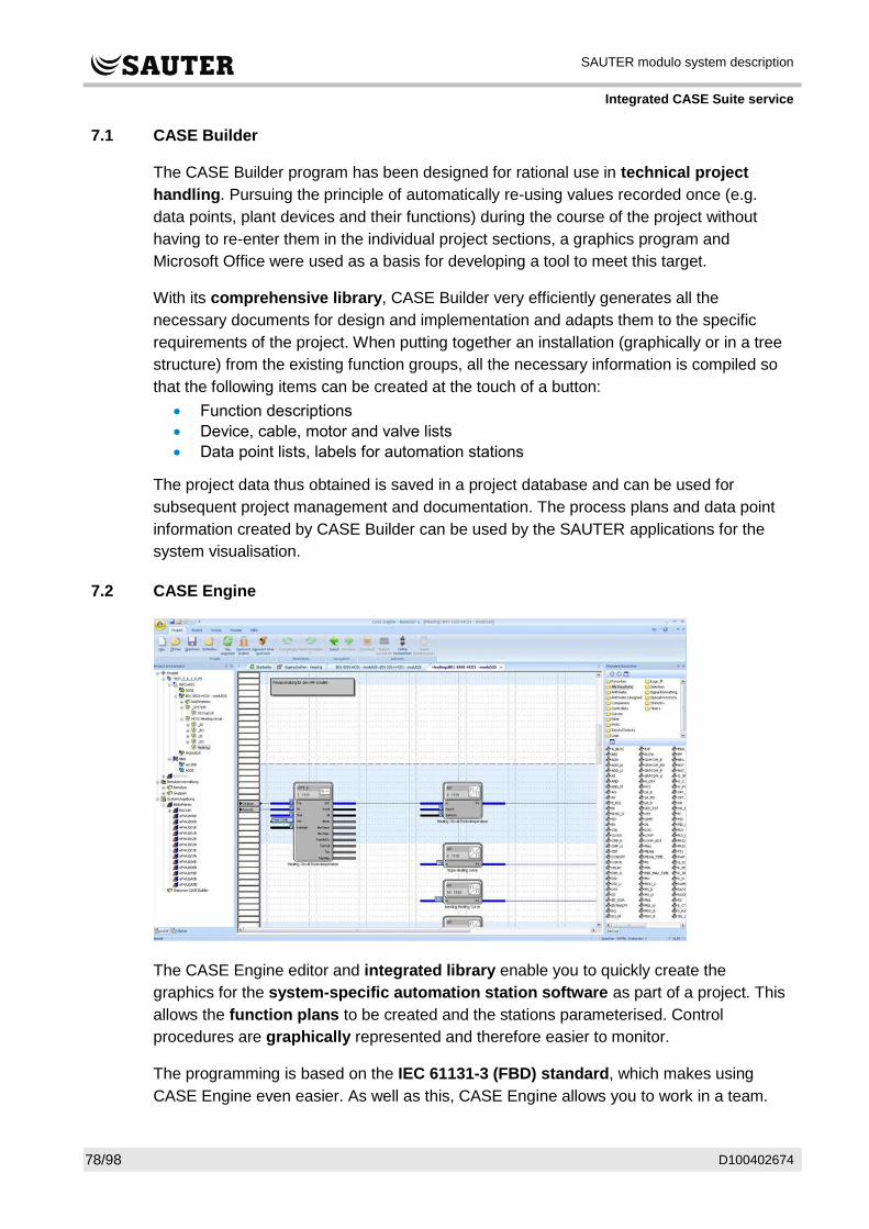
SAUTER modulo system description
Integrated CASE Suite service
D100402674
78/98
7.1 CASE Builder
The CASE Builder program has been designed for rational use in technical project
handling. Pursuing the principle of automatically re-using values recorded once (e.g.
data points, plant devices and their functions) during the course of the project without
having to re-enter them in the individual project sections, a graphics program and
Microsoft Office were used as a basis for developing a tool to meet this target.
With its comprehensive library, CASE Builder very efficiently generates all the
necessary documents for design and implementation and adapts them to the specific
requirements of the project. When putting together an installation (graphically or in a tree
structure) from the existing function groups, all the necessary information is compiled so
that the following items can be created at the touch of a button:
Function descriptions
Device, cable, motor and valve lists
Data point lists, labels for automation stations
The project data thus obtained is saved in a project database and can be used for
subsequent project management and documentation. The process plans and data point
information created by CASE Builder can be used by the SAUTER applications for the
system visualisation.
7.2 CASE Engine
The CASE Engine editor and integrated library enable you to quickly create the
graphics for the system-specific automation station software as part of a project. This
allows the function plans to be created and the stations parameterised. Control
procedures are graphically represented and therefore easier to monitor.
The programming is based on the IEC 61131-3 (FBD) standard, which makes using
CASE Engine even easier. As well as this, CASE Engine allows you to work in a team.
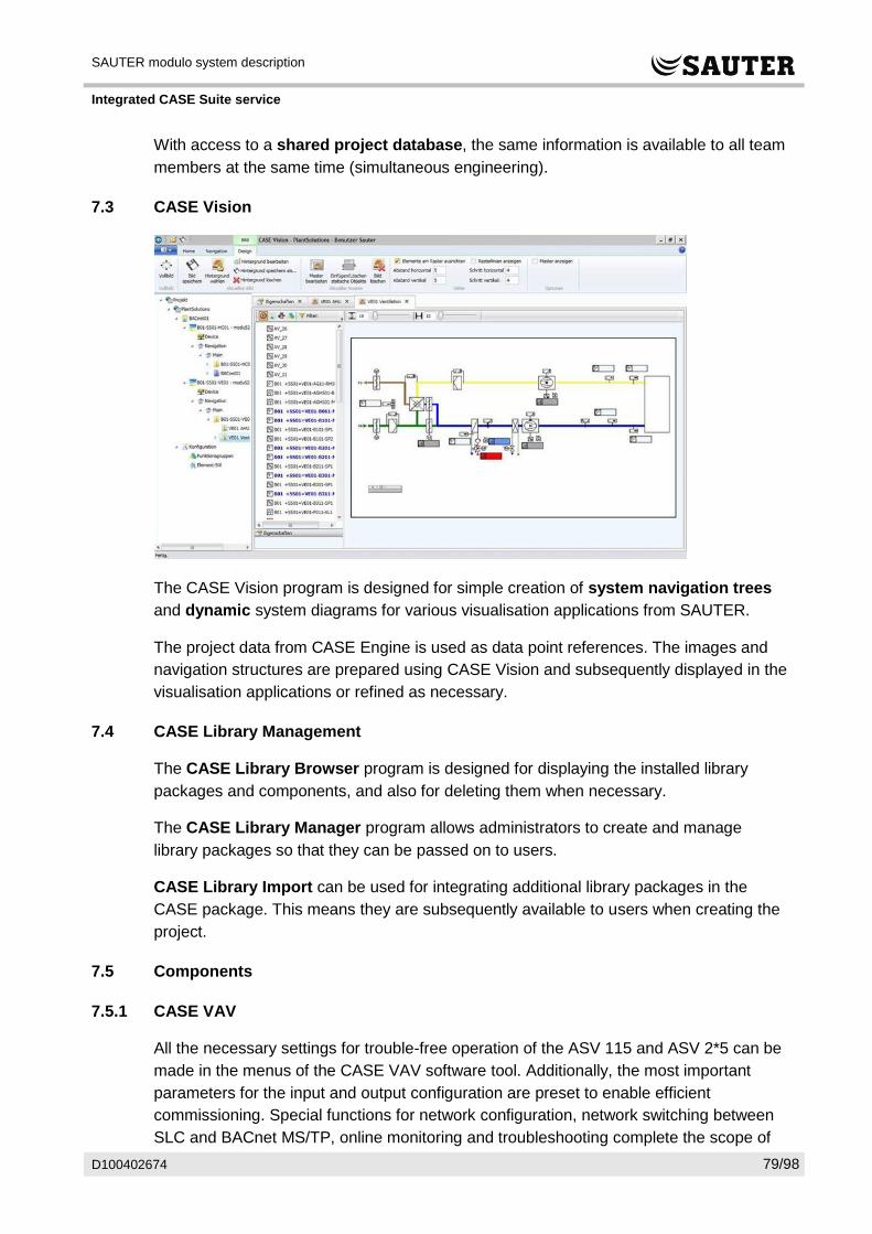
SAUTER modulo system description
Integrated CASE Suite service
D100402674
79/98
With access to a shared project database, the same information is available to all team
members at the same time (simultaneous engineering).
7.3 CASE Vision
The CASE Vision program is designed for simple creation of system navigation trees
and dynamic system diagrams for various visualisation applications from SAUTER.
The project data from CASE Engine is used as data point references. The images and
navigation structures are prepared using CASE Vision and subsequently displayed in the
visualisation applications or refined as necessary.
7.4 CASE Library Management
The CASE Library Browser program is designed for displaying the installed library
packages and components, and also for deleting them when necessary.
The CASE Library Manager program allows administrators to create and manage
library packages so that they can be passed on to users.
CASE Library Import can be used for integrating additional library packages in the
CASE package. This means they are subsequently available to users when creating the
project.
7.5 Components
7.5.1 CASE VAV
All the necessary settings for trouble-free operation of the ASV 115 and ASV 2*5 can be
made in the menus of the CASE VAV software tool. Additionally, the most important
parameters for the input and output configuration are preset to enable efficient
commissioning. Special functions for network configuration, network switching between
SLC and BACnet MS/TP, online monitoring and troubleshooting complete the scope of
SAUTER modulo system description
Integrated CASE Suite service
D100402674
80/98
functions. An integrated BACnet browser enables configuration of the ASV in BACnet
MS/TP mode.
7.5.2 CASE VAV Factory
User interface for downloading, with predefined parameterisation using CASE VAV, for
the ASV 115 and ASV 2*5 VAV compact controllers. Ideal for OEM customers and for
operation by users with little or no experience in VAV applications. The application offers
the following advantages:
The settings for ASV 115 and ASV 2*5 can be made with a few mouse-clicks and
without entering parameters.
Optimised throughput time when pre-setting the ASV 115 and ASV 2*5 at VAV box
manufacturers
Documentation of downloads in a log
7.5.3 CASE TPC (Touch Panel Configurator)
The CASE TPC software is designed for programming the EYT250 graphically. The
software not only makes it easy to create the function interface, but also to configure and
commission the EYT250 and to modify structures and parameters.
7.5.4 CASE Drives
CASE Drives is a program for commissioning the SAUTER ASM105SF132 and
ASM115SF132 damper actuators and the AVM105SF132 and AVM115SF132 valve
actuators. CASE Drives allows you to set and read the actuator parameters on site.
Connection is made using a serial interface on the PC.
7.5.5 CASE Sensors
CASE Sensors allows you to configure and monitor SAUTER sensors. All parameters
that can be modified using hardware operating elements can be set using this
application. It also makes other parameters available for setting, depending on the
device. CASE Sensors supports the following sensors: SGUF010/011 sash sensor and
EGP and SDX differential pressure sensors.
7.6 CASE Tools
The CASE tools offer various useful functions, including:
7.6.1 CASE Export
CASE Export allows information from the automation stations such as parameters of I/O
modules (house address, address text, dimensions etc.) to be made available to other
applications.
SAUTER modulo system description
Integrated CASE Suite service
D100402674
81/98
7.6.2 CASE Export BACnet
The CASE Export BACnet program creates EDE (Engineering Data Exchange) files
(Format 2) for BACnet stations (SAUTER EY-modulo 3, EY-modulo 5 and modulo 6) and
makes them available to other applications.
7.6.3 CASE Export novaNet
CASE Export novaNet provides three functions: Exporting BMT parameters without
groups (BMT 5.1), exporting BMT parameters with all tables (BMT 5.1 All Tables) and
exporting the EDE file.
7.6.4 CASE Import
During modernisation projects or if an old Automation Station fails, stations from the
EY2400 system are often replaced with state-of-the-art stations from the EY- modulo 5
system.
This is where CASE Import is used. The address designations of the EY2400 station do
not have to be typed in again, but can be transferred from the EY2400- FuPlan project to
a current EY-modulo 5 project with CASE Builder. As well as this, a terminal list with the
old and new terminal numbers is created so that the existing equipment can be very
easily connected to the EY-modulo 5 station.
7.6.5 BACnet Server Configurator
The IP address and other parameters of the novaNet-BACnet application master (EY-
modulo 5: EY-AM 300) are configured using the SAUTER BACnet Server Configurator
software module.
The configuration is transferred via the serial COM port (DB9 connector) or the Ethernet /
IP port and saved in a flash memory where it is protected from power failure. Data
transfer via IP takes place using the fixed TCP port 51966.
7.7 Communication
7.7.1 CASE HWC (hardware commissioning)
The hardware commissioning program is used to efficiently check the automation
stations (novaNet AS) of the system and the connected field devices. After the hardware
is commissioned, the program can be used for troubleshooting any initial errors.
7.7.2 CASE Sun
CASE Sun is the configuration tool for the Automation Stations and ecos stations in the
SAUTER EY-modulo 5 range. CASE Sun enables you to perform the Ethernet network
configuration, the 1:1 test during commissioning and update of the firmware on the
stations if necessary. CASE Sun is designed both for SAUTER service engineers and for
electricians on site.
SAUTER modulo system description
Integrated CASE Suite service
D100402674
82/98
The CASE TCM (CASE Touch Configuration Manager) application can be called up
directly from CASE Sun. CASE TCM is used for configuring the touch screen operating
devices for moduWeb Vision.
The SAUTER Licence Manager application can be used to license devices detected by
CASE Sun.
novaNet292 Configurator
The novaNet292 Configurator is for configuring the novaNet292 Ethernet access device,
setting the IP address of the port number etc.
novaVPort
novaVPort starts the communication driver for virtual COM ports. After selecting the
configured driver to be started, you can use the novaNet292 VirtualPort Monitor to view
the status and various information (such as version information) regarding novaNet292. If
no application is using the port, users can stop the novaVPort driver.
7.7.3 novaMit29x
novaMit29x is an analysis tool for the novaNet communication protocol. It can record
data transfer from the network and then analyse it.
7.7.4 Virtual Port Configurator
The Virtual Port Configurator visualises the settings of the virtual COM-Port drivers and
allows you to change them. The following ways to configure the virtual ports are
supported:
Communication with the moduNet292 device (novaVPort driver)
Communication between CASE VAV and the ASV actuators on the SLC bus connected to an ecos station
Communication between the SMI commissioning tool (Easy Monitor) and the devices on the SMI bus of an ecos communication module
SAUTER modulo system description
Further information
D100402674
83/98
8 Further information
The following topics are briefly summarised here:
BACnet communication protocol. The backbone of building automation.
8.1 BACnet Communication Protocol
8.1.1 BACnet
The BACnet used by the SAUTER modulo automation and room Automation Stations is
an open data communication protocol for building automation (Building Automation and
Control network). This manufacturer-neutral communication standard defines and
describes a “shared language” that supports data communication between different
systems (heating, ventilation, fire alarm and security) and, particularly, between devices
from different manufacturers. The aim is to keep installations open in the event of
expansions, replacements etc.
The BACnet standard is a development from ASHRAE (ASHRAE, 2016) (American
Society of Heating, Refrigerating and Air-Conditioning Engineers). It was established in
1987. In 1995, BACnet became an ASHRAE/ANSI standard and, in 2003, an
international standard (ISO 16484-5) and a European standard (EN ISO 16484-5). The
BACnet standard is developed continuously in different working groups.
For the mapping of the various elements of the BAS, the BACnet standard defines
standardised objects for the different data point types and for specific functions. Inputs,
outputs and setpoints have standardised objects for all of the supported data types, e.g.
analogue input object, binary output object and multi-state value object. Standardised
objects are also defined for schedules, calendars, PID control loops, protocols etc. Each
object has a set of properties, some of which are obligatory for the individual objects in
order to define them uniquely (Object_Identifier, Object_Type, Object_Name and
Property_List).
The standard also defines BACnet services for access to objects or for the execution of
functions. A total of 38 services are available (e.g. reading and writing object properties
or executing functions on other devices, such as restart, login for alarms etc.). In addition
to reading properties (e.g. the current value), there is also, and in particular, a service for
subscribing to a value. The value (the property) is then automatically reported by the
original object to the subscriber as soon as it changes (COV notification).
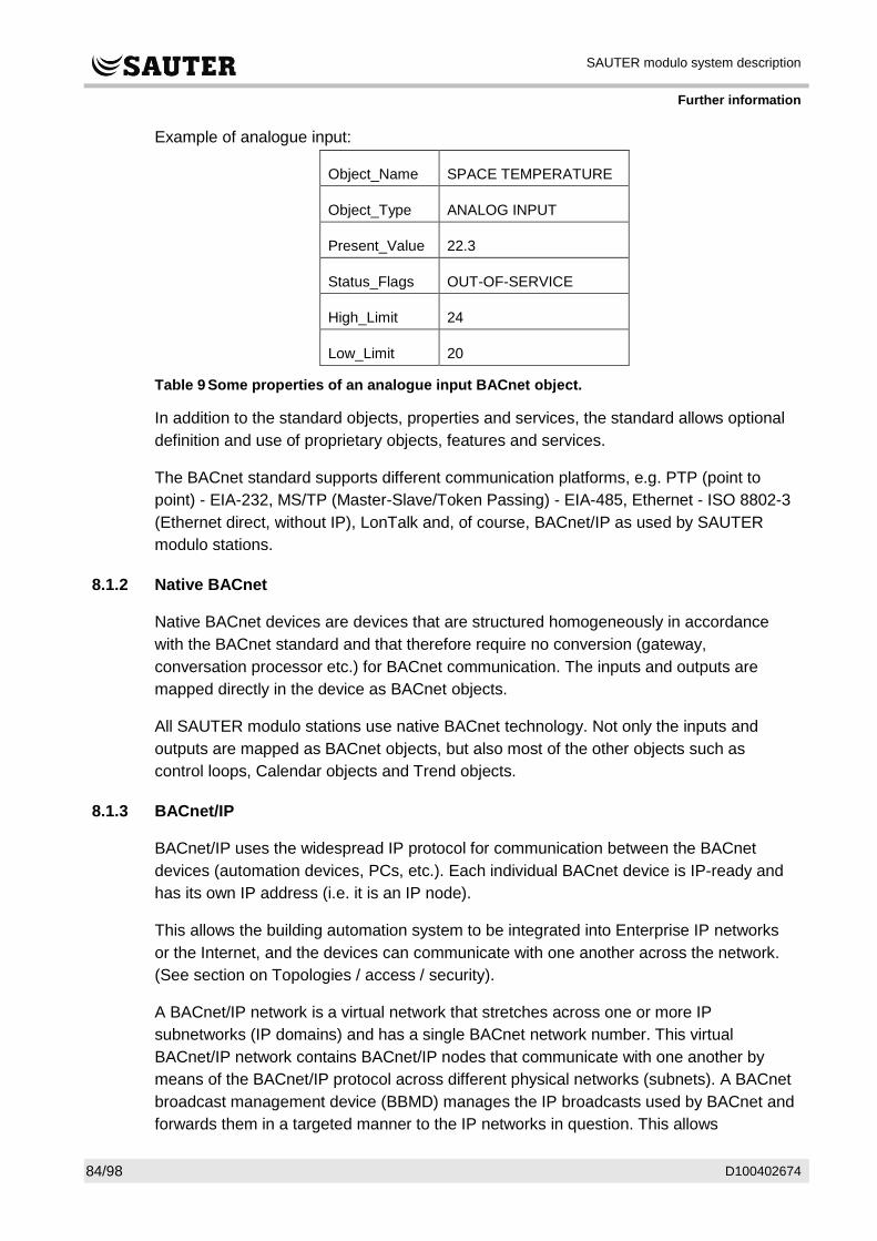
SAUTER modulo system description
Further information
D100402674
84/98
Example of analogue input:
Object_Name SPACE TEMPERATURE
Object_Type ANALOG INPUT
Present_Value 22.3
Status_Flags OUT-OF-SERVICE
High_Limit 24
Low_Limit 20
Table 9 Some properties of an analogue input BACnet object.
In addition to the standard objects, properties and services, the standard allows optional
definition and use of proprietary objects, features and services.
The BACnet standard supports different communication platforms, e.g. PTP (point to
point) - EIA-232, MS/TP (Master-Slave/Token Passing) - EIA-485, Ethernet - ISO 8802-3
(Ethernet direct, without IP), LonTalk and, of course, BACnet/IP as used by SAUTER
modulo stations.
8.1.2 Native BACnet
Native BACnet devices are devices that are structured homogeneously in accordance
with the BACnet standard and that therefore require no conversion (gateway,
conversation processor etc.) for BACnet communication. The inputs and outputs are
mapped directly in the device as BACnet objects.
All SAUTER modulo stations use native BACnet technology. Not only the inputs and
outputs are mapped as BACnet objects, but also most of the other objects such as
control loops, Calendar objects and Trend objects.
8.1.3 BACnet/IP
BACnet/IP uses the widespread IP protocol for communication between the BACnet
devices (automation devices, PCs, etc.). Each individual BACnet device is IP-ready and
has its own IP address (i.e. it is an IP node).
This allows the building automation system to be integrated into Enterprise IP networks
or the Internet, and the devices can communicate with one another across the network.
(See section on Topologies / access / security).
A BACnet/IP network is a virtual network that stretches across one or more IP
subnetworks (IP domains) and has a single BACnet network number. This virtual
BACnet/IP network contains BACnet/IP nodes that communicate with one another by
means of the BACnet/IP protocol across different physical networks (subnets). A BACnet
broadcast management device (BBMD) manages the IP broadcasts used by BACnet and
forwards them in a targeted manner to the IP networks in question. This allows
SAUTER modulo system description
Further information
D100402674
85/98
communication via several physical IP networks without placing unnecessary strain on
the overall network.
Topologies / access / security
BACnet/IP can, in principle, be operated in every IP network. (Even the moduWeb Unity
functions of the AS (operation with browser, e-mail) generally fit easily into every IP LAN
/ WAN / Internet environment.)
Due to the open design of BACnet/IP, SAUTER urgently recommends preventing all
BACnet/IP traffic with the Internet and all external access from the Internet to the
BACnet/IP network. SAUTER recommends following the recommendations of the
IEC 62443 standard. Customers should evaluate the dangers and the risks of their
solution and formulate the requirements accordingly.
One of the recommendations is to properly split the network into zones with strong
restrictions for the communication between zones. For example, it is common to split the
office LAN (IT, Enterprise Network) from the operations LAN (OT, Production LAN,
Building Automation LAN). Within the BA Network, only Building Automation devices are
connected and while this condition is respected, the use of BACnet/IP does not represent
a threat. To provide access to operational information from outside the network, either
Sauter Vision Center or the embedded web servers moduWeb, moduWeb Vision or
moduWeb Unity provide secure access and encrypted communication.
Depending on the project’s risk evaluation and cost, the BA may be directly integrated
into the customer’s IT infrastructure. During integration into an existing customer IP
network, it is generally recommended that the BMS components be logically separated
from the office LAN by bundling the building controllers and the BMS operating stations
into a VLAN (virtual LAN).
Except for very small systems, the bypassing of NAT router(s) and/or firewall(s) requires
either a BACnet router, or a VPN needs to be set up for access. Access via VPN is also
a very advisable solution. On the one hand, this is due to the clear delineation and thus
increased security and, on the other hand, due to the simpler configuration. Access via
VPN means that the operating stations on the Internet are integrated virtually in the
LAN/VLAN of the stations using appropriate VPN client drivers.
In any event, in order to allow external access, appropriate measures and configurations
must be performed for the Internet access and firewall.
For this reason, discussion and collaboration with the customer’s IT managers – even
during the planning phase – is indispensable for the implementation in the customer’s IT
environment.
8.1.4 BACnet/MSTP
BACnet/MSTP uses the widespread RS-485 as the physical layer (see Figure 5). In
contrast to IP, the reduced bandwidth and linear topology present significant restrictions
SAUTER modulo system description
Further information
D100402674
86/98
that limit the reactivity of the BACnet communication. Important latency times compared
to BACnet/IP must be taken into account.
The operating principle of BACnet/MSTP is firstly based on differentiating between
master and slave participants, whereby master devices exclusively send requests and
slave devices can exclusively respond. Secondly, the token is passed from device to
device and only the device with the token can send requests. There is no need to have
the token to send answers. This operating mode supports basic BACnet functions such
as device restoring. However, the limitations of RS-485 and MSTP mean that
BACnet/MSTP is not designed for LAN operation. Instead, it is well suited for short
branches with a limited number of devices like sensors and actuators.
8.1.5 BACnet/SC
The digital revolution has brought many benefits but also some additional risks.
Cybersecurity is a critical topic when strategic assets and facilities are at stake. With
BACnet Secure Communication, the BACnet protocol is encrypted and can be easily
integrated into the IT topology and the Internet.
Based on WebSockets and TLS, this evolution of the BACnet protocol provides BACnet
with standardised security mechanisms for encryption to secure data confidentiality.
BACnet/SC is described in Addenda 135-2016bj and includes important changes with
respect to BACnet/IP (see Figure 6). The use of TLS is not an option but intrinsic to the
Secure Communication. Thus, certificate management is one of the requirements that
must be fulfilled when setting up a BACnet/SC network. Further, TCP is used instead of
UDP. Because WebSockets are used, standard port 443 is used instead of 47808
(BAC0). Another important aspect is that communication is basically centralised in a hub,
following a hub and spoke model. Nevertheless, node to node communication is still
possible.
Fehler! Verweisquelle konnte nicht gefunden werden. represents a topology
combining BACnet/SC and BACnet/IP networks. A routing device must be used between
the two networks. For security reasons, the routing is not completely transparent, as it
would make no sense that an unsecured device in the BACnet/IP network would be
allowed to send commands to the BACnet/SC network.
An additional benefit of BACnet/SC is that it can work in IPv4 and IPv6 networks. Figure
6 represents the construction of BACnet/SC following the OSI layer model.
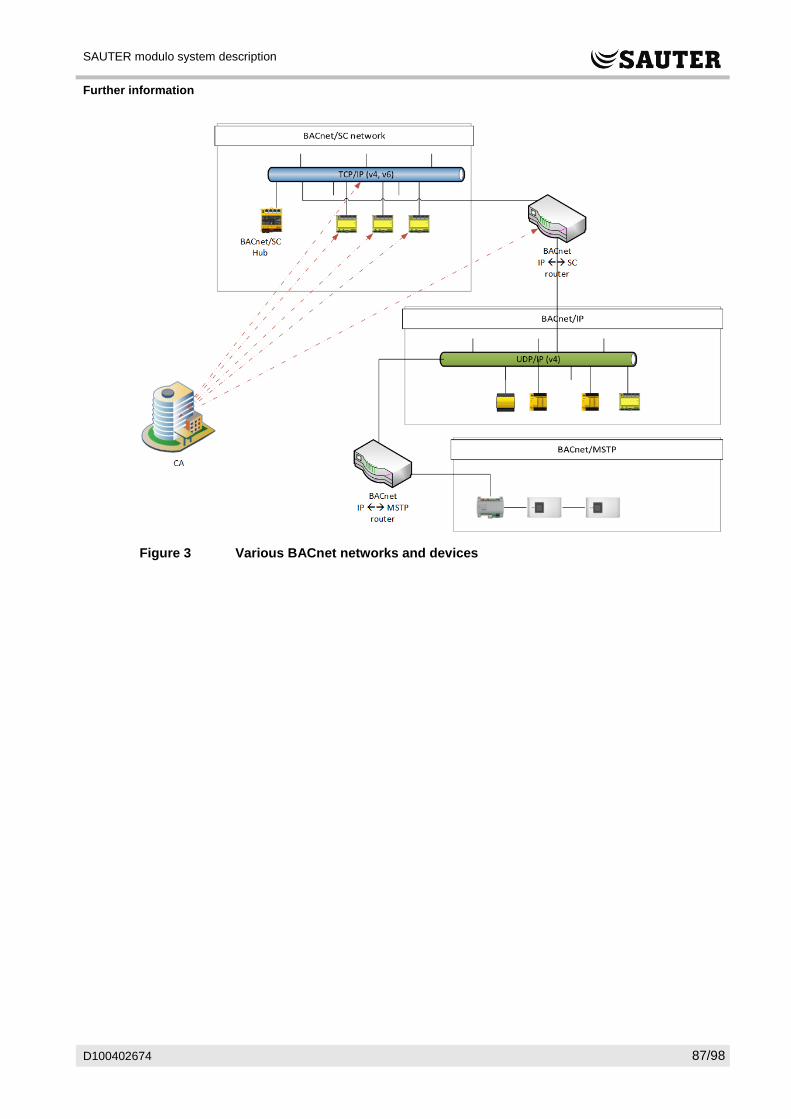
SAUTER modulo system description
Further information
D100402674
87/98
Figure 3 Various BACnet networks and devices

SAUTER modulo system description
Further information
D100402674
88/98
Figure 4 Hub and spoke topology of BACnet/SC. While the BACnet/SC
communication is centralised in the hub, the BACnet/IP communication is station to
station or broadcast.
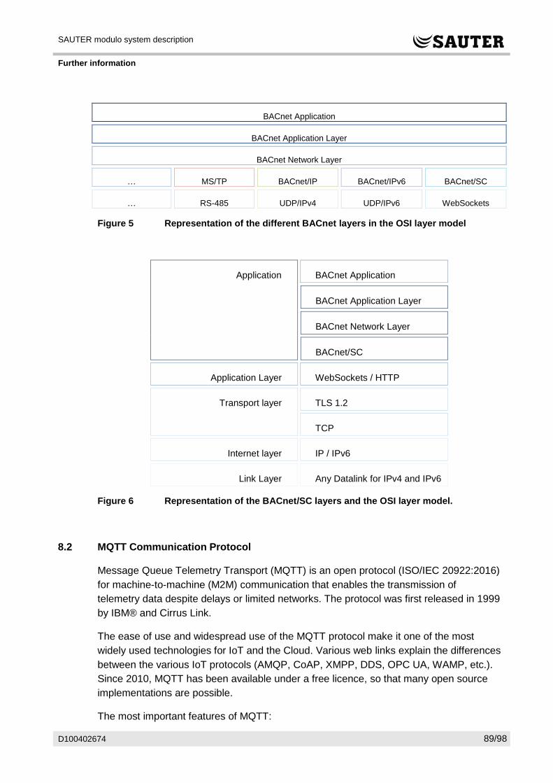
SAUTER modulo system description
Further information
D100402674
89/98
BACnet Application
BACnet Application Layer
BACnet Network Layer
… MS/TP BACnet/IP BACnet/IPv6 BACnet/SC
… RS-485 UDP/IPv4 UDP/IPv6 WebSockets
Figure 5 Representation of the different BACnet layers in the OSI layer model
Application BACnet Application
BACnet Application Layer
BACnet Network Layer
BACnet/SC
Application Layer WebSockets / HTTP
Transport layer TLS 1.2
TCP
Internet layer IP / IPv6
Link Layer Any Datalink for IPv4 and IPv6
Figure 6 Representation of the BACnet/SC layers and the OSI layer model.
8.2 MQTT Communication Protocol
Message Queue Telemetry Transport (MQTT) is an open protocol (ISO/IEC 20922:2016)
for machine-to-machine (M2M) communication that enables the transmission of
telemetry data despite delays or limited networks. The protocol was first released in 1999
by IBM® and Cirrus Link.
The ease of use and widespread use of the MQTT protocol make it one of the most
widely used technologies for IoT and the Cloud. Various web links explain the differences
between the various IoT protocols (AMQP, CoAP, XMPP, DDS, OPC UA, WAMP, etc.).
Since 2010, MQTT has been available under a free licence, so that many open source
implementations are possible.
The most important features of MQTT:
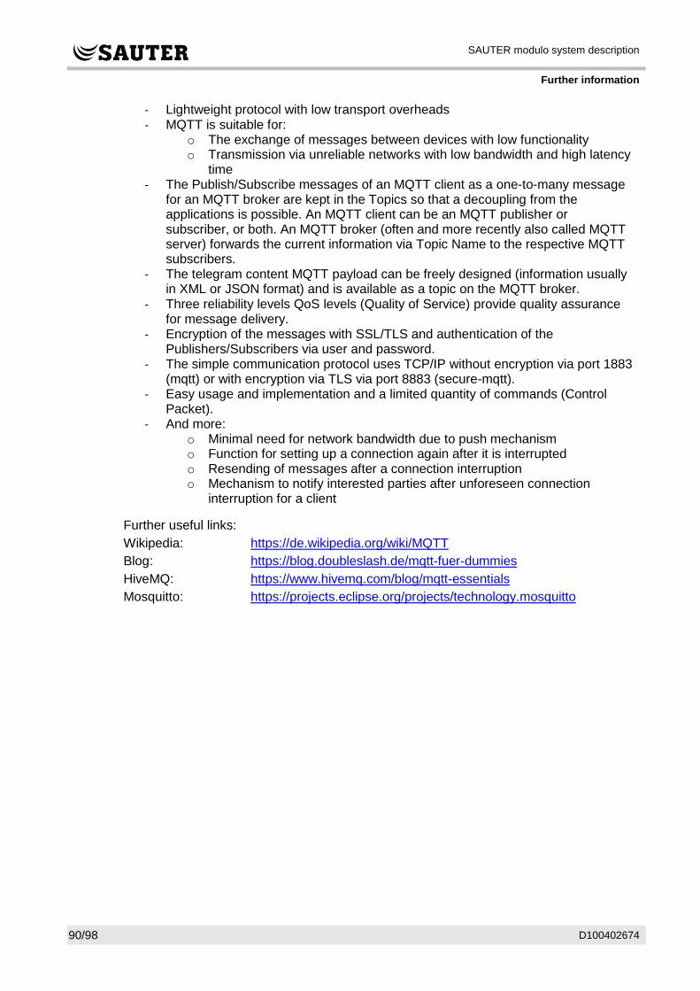
SAUTER modulo system description
Further information
D100402674
90/98
- Lightweight protocol with low transport overheads - MQTT is suitable for:
o The exchange of messages between devices with low functionality o Transmission via unreliable networks with low bandwidth and high latency
time - The Publish/Subscribe messages of an MQTT client as a one-to-many message
for an MQTT broker are kept in the Topics so that a decoupling from the applications is possible. An MQTT client can be an MQTT publisher or subscriber, or both. An MQTT broker (often and more recently also called MQTT server) forwards the current information via Topic Name to the respective MQTT subscribers.
- The telegram content MQTT payload can be freely designed (information usually in XML or JSON format) and is available as a topic on the MQTT broker.
- Three reliability levels QoS levels (Quality of Service) provide quality assurance for message delivery.
- Encryption of the messages with SSL/TLS and authentication of the Publishers/Subscribers via user and password.
- The simple communication protocol uses TCP/IP without encryption via port 1883 (mqtt) or with encryption via TLS via port 8883 (secure-mqtt).
- Easy usage and implementation and a limited quantity of commands (Control Packet).
- And more: o Minimal need for network bandwidth due to push mechanism o Function for setting up a connection again after it is interrupted o Resending of messages after a connection interruption o Mechanism to notify interested parties after unforeseen connection
interruption for a client
Further useful links:
Wikipedia: https://de.wikipedia.org/wiki/MQTT
Blog: https://blog.doubleslash.de/mqtt-fuer-dummies
HiveMQ: https://www.hivemq.com/blog/mqtt-essentials
Mosquitto: https://projects.eclipse.org/projects/technology.mosquitto
SAUTER modulo system description
Further information
D100402674
91/98
Further useful sources:
ISO/IEC 20922:2016: https://www.iso.org/standard/69466.html
MQTTOrganisation: http://mqtt.org/
OASIS Organisation: https://www.oasis-
open.org/committees/tc_home.php?wg_abbrev=mqtt
Since MQTT is a public, licence-free standard, there are many community platforms in
addition to the commercial Cloud platforms (Amazon AWS, IBM Cloud/Bluemix, Google
Cloud, Microsoft Azure, etc).
SAUTER modulo system description
Further information
D100402674
92/98
Glossary
A
AI Analog Input ........................................... 36, 40
BACnet Analog Input .............................. 19, 22
AMQP Advanced Message Queuing Protocol .......... 89
ANSI American National Standards Institute .... 47, 83
AO Analog Output ......................................... 39, 40
BACnet Analog Output ........................... 19, 22
API Application programming Interface .. 19, 22, 27,
71, 74, 75
Application Programming Interface ................. 7
ASHRAE American Society of Heating, Refrigerating and
Air-Conditioning Engineers ....................... 83
AV BACnet Analog Value ............................. 19, 22
B
BACnet Building automation and control network . 7, 11,
12, 13, 14, 17, 19, 20, 22, 23, 25, 28, 44,
45, 46, 47, 49, 50, 51, 53, 54, 58, 59, 60,
61, 62, 63, 74, 75, 79, 80, 81, 83, 84, 85,
86, 87, 88, 89
BAS Building Automation System ............. 11, 12, 55
B-BC BACnet Building Controller ........................... 19
BI BACnet Binary Input ............................... 19, 22
BLND_O Sauter Blind Output (Proprietary)............ 19, 22
BLND_O2 Sauter Blind Output 2 (Proprietary)......... 19, 22
BMS Building Management System .......... 13, 55, 85
BO BACnet Binary Output ............................ 19, 22
BV BACnet Analog Value ............................. 19, 22
C
CAL BACnet Calendar.................................... 19, 22
CASE Computer Aided Sauter Engineering 11, 21, 24
CI Counter Input .............................. 35, 36, 39, 40
CoAP Constrained Application Protocol.................. 89
CSS3 Cascading Style Sheets Level 3 ................... 55
D
DALI Digital Addressable Lighting Interface ... 16, 45,
53, 54, 59, 60, 61, 74
DDS Data Distribution Service .............................. 89
DEV BACnet Device ....................................... 19, 22
DI Digital Input ................................ 35, 36, 39, 40
DIM_O Sauter Dimmable Output (Proprietary) ... 19, 22
DO Digital Output ................................................ 38
E
EE BACnet Event Enrollment ....................... 19, 22
EIA Electronic Industries Alliance .................. 47, 84
EL BACnet Event Log .................................. 19, 22
F
ftp File Transfer Protocol ................................... 55
G
GND Earth ............................................................. 19
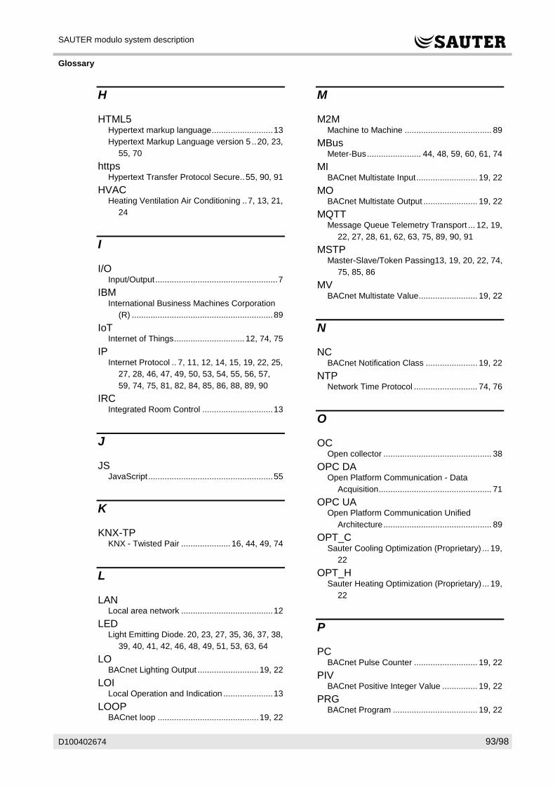
SAUTER modulo system description
Glossary
D100402674
93/98
H
HTML5 Hypertext markup language .......................... 13
Hypertext Markup Language version 5 .. 20, 23,
55, 70
https Hypertext Transfer Protocol Secure.. 55, 90, 91
HVAC Heating Ventilation Air Conditioning .. 7, 13, 21,
24
I
I/O Input/Output .................................................... 7
IBM International Business Machines Corporation
(R) ............................................................ 89
IoT Internet of Things .............................. 12, 74, 75
IP Internet Protocol .. 7, 11, 12, 14, 15, 19, 22, 25,
27, 28, 46, 47, 49, 50, 53, 54, 55, 56, 57,
59, 74, 75, 81, 82, 84, 85, 86, 88, 89, 90
IRC Integrated Room Control .............................. 13
J
JS JavaScript ..................................................... 55
K
KNX-TP KNX - Twisted Pair ..................... 16, 44, 49, 74
L
LAN Local area network ....................................... 12
LED Light Emitting Diode . 20, 23, 27, 35, 36, 37, 38,
39, 40, 41, 42, 46, 48, 49, 51, 53, 63, 64
LO BACnet Lighting Output .......................... 19, 22
LOI Local Operation and Indication ..................... 13
LOOP BACnet loop ........................................... 19, 22
M
M2M Machine to Machine ..................................... 89
MBus Meter-Bus ....................... 44, 48, 59, 60, 61, 74
MI BACnet Multistate Input .......................... 19, 22
MO BACnet Multistate Output ....................... 19, 22
MQTT Message Queue Telemetry Transport ... 12, 19,
22, 27, 28, 61, 62, 63, 75, 89, 90, 91
MSTP Master-Slave/Token Passing13, 19, 20, 22, 74,
75, 85, 86
MV BACnet Multistate Value ......................... 19, 22
N
NC BACnet Notification Class ...................... 19, 22
NTP Network Time Protocol ........................... 74, 76
O
OC Open collector .............................................. 38
OPC DA Open Platform Communication - Data
Acquisition ................................................ 71
OPC UA Open Platform Communication Unified
Architecture .............................................. 89
OPT_C Sauter Cooling Optimization (Proprietary) ... 19,
22
OPT_H Sauter Heating Optimization (Proprietary) ... 19,
22
P
PC BACnet Pulse Counter ........................... 19, 22
PIV BACnet Positive Integer Value ............... 19, 22
PRG BACnet Program .................................... 19, 22
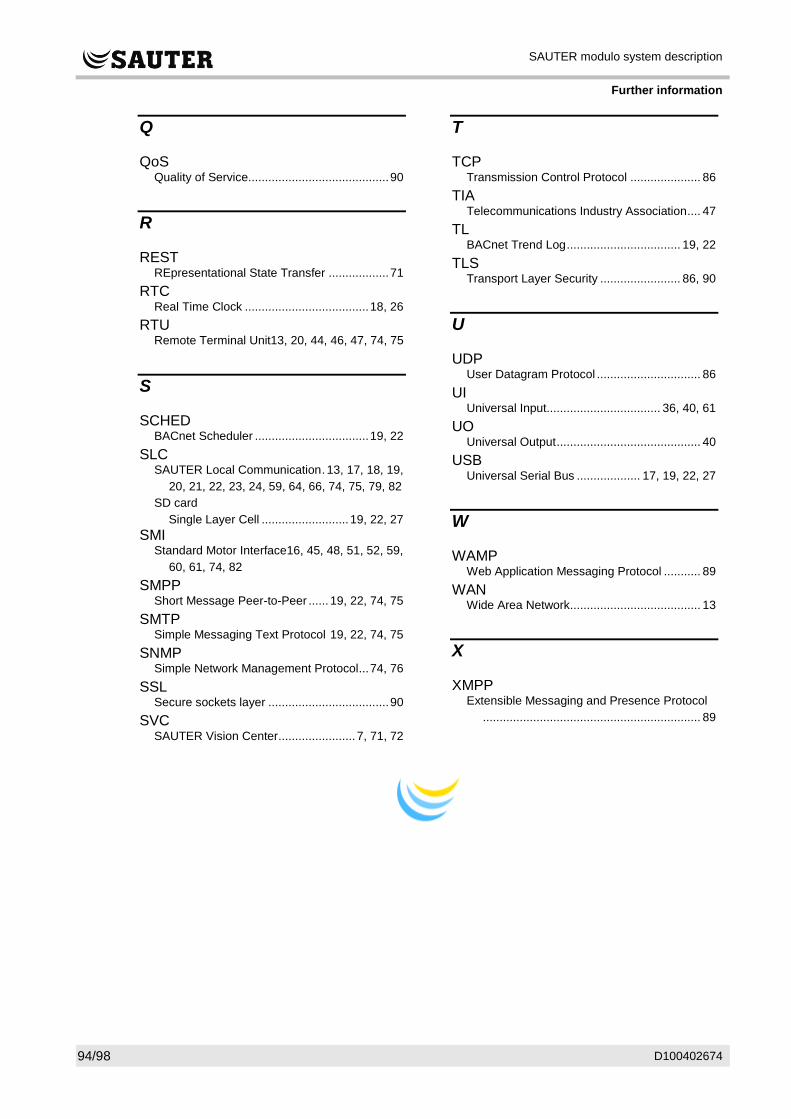
SAUTER modulo system description
Further information
D100402674
94/98
Q
QoS Quality of Service.......................................... 90
R
REST REpresentational State Transfer .................. 71
RTC Real Time Clock ..................................... 18, 26
RTU Remote Terminal Unit13, 20, 44, 46, 47, 74, 75
S
SCHED BACnet Scheduler .................................. 19, 22
SLC SAUTER Local Communication . 13, 17, 18, 19,
20, 21, 22, 23, 24, 59, 64, 66, 74, 75, 79, 82
SD card
Single Layer Cell .......................... 19, 22, 27
SMI Standard Motor Interface16, 45, 48, 51, 52, 59,
60, 61, 74, 82
SMPP Short Message Peer-to-Peer ...... 19, 22, 74, 75
SMTP Simple Messaging Text Protocol 19, 22, 74, 75
SNMP Simple Network Management Protocol ... 74, 76
SSL Secure sockets layer .................................... 90
SVC SAUTER Vision Center ....................... 7, 71, 72
T
TCP Transmission Control Protocol ..................... 86
TIA Telecommunications Industry Association .... 47
TL BACnet Trend Log .................................. 19, 22
TLS Transport Layer Security ........................ 86, 90
U
UDP User Datagram Protocol ............................... 86
UI Universal Input.................................. 36, 40, 61
UO Universal Output ........................................... 40
USB Universal Serial Bus ................... 17, 19, 22, 27
W
WAMP Web Application Messaging Protocol ........... 89
WAN Wide Area Network ....................................... 13
X
XMPP Extensible Messaging and Presence Protocol
................................................................. 89
SAUTER modulo system description
List of figures
D100402674
95/98
List of figures
Figure 1 modulo 6 connectivity. ............................................................................................. 12
Figure 2 Graphical user interface .......................................................................................... 43
Figure 3 Various BACnet networks and devices ................................................................... 87
Figure 4 Hub and spoke topology of BACnet/SC. While the BACnet/SC
communication is centralised in the hub, the BACnet/IP communication is
station to station or broadcast. ................................................................................ 88
Figure 5 Representation of the different BACnet layers in the OSI layer model ................... 89
Figure 6 Representation of the BACnet/SC layers and the OSI layer model. ....................... 89
SAUTER modulo system description
Further information
D100402674
96/98
List of tables
Table 1 Compilation of signals available on each I/O module. ............................................ 34
Table 2 The table shows which is the standard, default variant on each device, and
which upgrades are possible. .................................................................................. 56
Table 3 References for upgrading the web server ............................................................... 56
Table 4 Main menu nodes for each web server variant. Double ticks indicate
enhancement. .......................................................................................................... 56
Table 5 Available references and related interfaces. ● 1 Interface, ●● 2 Interfaces. .......... 60
Table 6 Functions additionally activated in EY-RC504 ........................................................ 61
Table 7 Overview of modulo 6 integration solutions for different technologies. ................... 74
Table 8 Network services that can be optionally supported by some modulo 6
stations. ................................................................................................................... 76
Table 9 Some properties of an analogue input BACnet object. ........................................... 84

SAUTER modulo system description
D100402674
98/98
© Fr. Sauter AG Im Surinam 55 CH-4016 Basle Tel. +41 61 - 695 55 55 Fax +41 61 - 695 55 10 www.sauter-controls.com
nte
d in
Sw
itze
rla
nd