save energy and reduce electricity costs - abb group€¦ · save energy and reduce electricity...
TRANSCRIPT

Save energy and reduceelectricity costs
Power factor correction
Improve energy efficiency
Reduces system currents and saves kw losses.
Eliminates reactive power charges
Excess kvar charges and power factor adjustments
all eliminated. Supply kVA reduced.
Releases additional capacity
Operating current capacity in transformers,
switchgear and supply cables made available.
Security of supply
Reduces peak currents to prevent fuse failure and
loss of supply.
Environmentally friendly
Reduces kwh losses on the system and consequent
harmful generation of CO2.
00010 Emtac flyerv1.indd 100010 Emtac flyerv1.indd 1 10/4/06 9:26:08 am10/4/06 9:26:08 am
2 ABB
Power factor is the relationship between working (active) power and total power consumed (apparent power). Essentially, power factor is a measurement of how effectively electrical power is being used. The higher the power factor, the more effectively electrical power is being used and vice versa. A distribution system’s operating power is composed of two parts: Active (work-ing) power and reactive (non-working) magnetising power. The ACTIVE power performs the useful work ... the REACTIVE power does not as its only function is to develop magnetic fields required by inductive devices.
Why improve low power factor?
Low power factor means poor electrical efficiency.
The lower the power factor, the higher the apparent
power drawn from the distribution network.
When low power factor is not corrected, the
utility must provide the non-working reactive power
in addition to the working active power. This results
in the use of larger generators, transformers, bus
bars, cables, and other distribution system devices,
that otherwise would not be necessary. As the
utility’s capital expenditures and operating costs are
going to be higher, they are going to pass these
higher expenses down the line to industrial users in
the form of power factor penalties.
Basic concept
Most loads on an electrical distribution system can
be placed in one of three categories: Resistive,
Inductive or Capacitive.
The most common of these three on modern
systems is the inductive load. Typical examples
include transformers, fluorescent lighting and AC
induction motors. All inductive loads require two
kinds of power to function properly:
• Active power (kW) - actually performs
the work
• Reactive Power (kvar) - sustains the
electro-magnetic field
As an example with an unloaded AC motor, one
might expect the no-load current to drop near zero.
In truth, however, the no-load current will generally
show a value between 25% and 30% of full load
current. This is because of the continuous demand
for magnetising current by any induction load.
How to produce reactive power
In electrical terms, capacitance is
also considered as a “reactive power”
component but in fact its characteristic
in an electric circuit is to neutralise
or compensate for the inductive
reactive power.
Thus we have an item of electrical
equipment which can be used to
effectively offset a proportion of the
reactive power drawn from the supply.
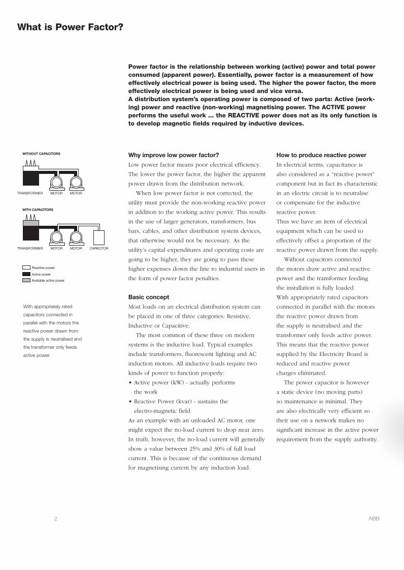
Without capacitors connected
the motors draw active and reactive
power and the transformer feeding
the installation is fully loaded.
With appropriately rated capacitors
connected in parallel with the motors
the reactive power drawn from
the supply is neutralised and the
transformer only feeds active power.
This means that the reactive power
supplied by the Electricity Board is
reduced and reactive power
charges eliminated.
The power capacitor is however
a static device (no moving parts)
so maintenance is minimal. They
are also electrically very efficient so
their use on a network makes no
significant increase in the active power
requirement from the supply authority.
REMROFSNART
SROTICAPAC TUOHTIW
SROTICAPAC HTIW
REMROFSNART
ROTOM
rewop evitcaeR
rewop evitcA
evitca elbailavA rewop
ROTOM
ROTICAPACROTOMROTOM
What is Power Factor?
With appropriately rated
capacitors connected in
parallel with the motors the
reactive power drawn from
the supply is neutralised and
the transformer only feeds
active power.
00010 Emtac flyerv1.indd 200010 Emtac flyerv1.indd 2 10/4/06 9:26:09 am10/4/06 9:26:09 am

3ABB
Powerful and compact
• High power density
– small dimensions
• Proven technology
CLMD capacitors
Easy to select
• 4 executions: 2 wall mount
& 2 floor mount cubicles
• Complete range
• Acute regulation
Easy to install
• Complete factory tested unit
ready for connection
• Ample wiring space
• Wall fixations (A50, A100)
• Lifting lugs and floor mount
(A200, A400)
• Bottom cable entry
(optional top entry)
Easy to operate
RVC PF controller with
• Complete auto set-up
• Easy commissioning
• User-friendly interface
• Easy access to parameters
for manual setting
Reliable and safe
• IP42 protection (closed door)
• Protected against direct
contact (open door)
• HRC fuses
• Use of ABB components:
– PF Controller
– CLMD capacitors
The user-friendly PF controller
• Easy commissioning
• Complete auto set-up (starting current-C/k,
number of active outputs, type of switching
sequence, phase shift, special connections).
• Easy to use thanks to a user-friendly
interface and ease of access to parameters for
manual setting
• Highly efficient switching strategy combining
integral, direct and circular switching. This
allows to:
– control the cos ϕ in presence of rapidly
varying loads
– reduce the number of switchings
– avoid unnecessary intermediary switchings
– increase the lifetime of the capacitors
and contactors
• Suitable for hot environments thanks to max.
ambient temperature rating of 70°C
• Insensitivity to the presence of harmonics
• Overvoltage and undervoltage protection
• An alarm contact is closed when the target
cos ϕ is not reached within 6 minutes after all
outputs have been switched on, the internal
temperature of the RVC rises above 85°C or the
power supply is out of range
Advance automatic capacitor banks
PowerIT factor controller RVC, the user friendly PF controller
Cubicle protective device
MCCB can be included within the
enclosure and interlocked with the
main access door to provide complete
cubicle protection.
Auto control
Each ADVANCE Automatic cubicle has
standard stage modules complete with
appropriate contactors, line fuses and
control circuitry.
Control relay
A multi-stage reactive kVAR control relay
can be provided inside the assembly with
PFI and stage on indication.
Selector switches
Each stage can be provided with selector
switches and stage on indication.
Future extension
Modular switching section trays
incorporating appropriate capacitor
units, contactors and line fuses and are
available for future extension.
Advance PFC equipment range
00010 Emtac flyerv1.indd 300010 Emtac flyerv1.indd 3 10/4/06 9:26:10 am10/4/06 9:26:10 am

ABB LimitedRossmore Road East, Ellesmere PortSouth Wirral CH65 3DDTel: +44 (0)151 357 8400Fax: +44 (0)151 355 9137
email [email protected]/uk
A comprehensive solution for active filtering of harmonics
The ABB Power Quality Filter offers unprecedented ability to clean the network from
harmonics. The PQF actively eliminates the harmonics present in the supply system in
a controlled way. It is insensitive to large network impedance changes due to change
in network topology like paralleling of sources, or switching between mains supply and
generator operation.
The PQF monitors the line current in real time
and processes the measured harmonics as digital
signals in a high-power multi-DSP (Digital Signal
Processor) based system. The digital controller
generates Pulse Width Modulated (PWM) signals
that drive IGBT power modules which through line
reactors inject harmonic currents in the network with
exactly the opposite phase to the components that
are to be filtered.
The PQF also offers communication facilities with
the customer’s existing communication network. This
feature which uses Modbus RTU, allows the PQF to
be easily monitored and controlled from a remote
location. The Modbus communication feature can
be used by means of an RS-232 to RS-485 converter
(optional).
Advantages of the PQF
• Filters up to 20 harmonics simultaneously
• Filters up to the 50th harmonic
• Harmonic attenuation factor better than 97%
• Fulfilment of International Guidelines like G5/4,
IEEE 519, etc
• Filters with closed loop control for best accuracy
• Is not overloadable
• Has a programmable filtering strategy and free
choice of harmonics selection
• Fault and event logging with real time stamp
• Direct connection up to 690V
• Top or bottom cable entry (optional for PQFI)
• Easy commissioning – Auto-detection of network
frequency and CT Polarity
• May filter without generation of reactive power
• May generate reactive power and control
power factor
• May balance the load current across the phases
• Has programmable task priorities
• Does not require detailed network analysis
• Does not require special CTs
• Is easy to extend on site
• Comes factory tested
• Auto-adaptation to network impedance changes
• Optical fibre isolation between power and
control stages
• Programmable stand-by and re-start functions
• Programmable digital I/O interface
• Modbus RTU communication compatible
• Two sets of compensation parameters for different
load type compensation.
PowerIT PQF range LV Active Filters PQFS – PQFI – PQFM – PQFK
00010 Emtac flyerv1.indd 400010 Emtac flyerv1.indd 4 10/4/06 9:26:12 am10/4/06 9:26:12 am