say cheese!: experiences with a robot photographer · say cheese!: experiences with a robot...
TRANSCRIPT
Say Cheese!: Experiences with a Robot Photographer
Zachary Byers and Michael Dixon and William D. Smart and Cindy M. GrimmDepartment of Computer Science and Engineering
Washington University in St. LouisSt. Louis, MO 63130
United States{zcb1,msd2,wds,cmg }@cse.wustl.edu
Abstract
We have developed an autonomous robot system that takeswell-composed photographs of people at social events, suchas weddings and conference receptions. The robot, Lewis,navigates through the environment, opportunistically takingphotographs of people. In this paper, we outline the over-all architecture of the system and describe how the variouscomponents inter-relate. We also describe our experiences ofdeploying the robot photographer at a number of real-worldevents.
IntroductionIn this paper, we describe our experiences with an au-tonomous photography system mounted on a mobile robot.The robot navigates around social events, such as weddingreceptions and conference receptions, opportunistically tak-ing photographs of the attendees. The system is capable ofoperating in unaltered environments, and has been deployedat a number of real-world events.
This paper gives an overview of the entire robot photog-rapher system, and details of the architecture underlying theimplementation. We discuss our experiences with deployingthe system in several environments, including a scientificconference and an actual wedding, and how it performed.We also attempt to evaluate the quality of the photographstaken, and discuss opportunities for improvement.
The system is implemented with two digital cameras (onestill and one video), mounted on an iRobot B21r mobilerobot platform. The robot stands slightly over four feet tall,and is a bright red cylinder approximately two feet in di-ameter. The cameras are mounted on top of the robot on aDirected Perception pan/tilt unit. All computation is doneon-board, on a Pentium-III 800MHz system. The only sen-sors used for this project are the cameras and a laser range-finder, which gives 180 radial distance measurements overthe front 180◦ of the robot, in a plane approximately onefoot above the floor. The robot communicates with a remoteworkstation, where photographs can be displayed, using awireless Ethernet link.
At a high level, the system works as follows. The robotnavigates around the room, continually looking for “good”
Copyright c© 2003, American Association for Artificial Intelli-gence (www.aaai.org). All rights reserved.
photograph opportunities. A face-detection system thatfuses data from a video camera and the laser range-finderlocates the position of faces in the scene. These faces arethen analyzed by a composition system, based on a few sim-ple rules from photography, and a “perfect” framing of thescene is determined. The camera then pans, tilts and zoomsin an attempt to match this framing, and the photograph istaken.
In the remainder of the paper, we discuss our motivationfor undertaking this project and describe the various aspectsof the system. We then describe some of the major deploy-ments of the system, and show examples of the photographsthat it took. Finally, we offer some conclusions, based onour experiences, attempt to evaluate the performance of thecurrent system, and suggest future directions for research.
MotivationWhy robot photography? Our primary research interestsare in the areas of long-term autonomy, autonomous navi-gation, and robot-human interaction. The robot photogra-pher project started as a framework within which we coulddo that research. It was also designed to be appealing toundergraduates, and to encourage them to get involved inresearch. Automated photography is a good choice of ap-plication, since it incorporates all of the basic problemsof mobile robotics (such as localization, navigation, path-planning,etc.), is easily accessible to the general public (ev-eryone knows what a photographer does), and has a multi-disciplinary element (how do you automate the skill of pho-tograph composition).
Because the concept of a robot photographer is easily un-derstood by the public, it is an excellent umbrella underwhich to study human-robot interaction. Members of thepublic who have seen the system have responded very pos-itively to it, and have been very willing to interact with therobot. Since the application is accessible to people withouttechnical knowledge of robotics and computer science, theinteractions that people have with the system tend to be verynatural.
Our original goals were to create a system that was able toautonomously navigate crowded rooms, taking candid, well-composed pictures of people. The intent was to have an au-tomated event photographer, and to catch pictures of peopleinteracting with each other, rather than standard “mug-shot”
IAAI 2003 65

GUI
VideoCamera
FaceFinder
SelectionDestination
DigitalCamera
PathPlanning Navigation
Framing
Take Picture
Image LocationGrab
WirelessLink
Photography System
World Location
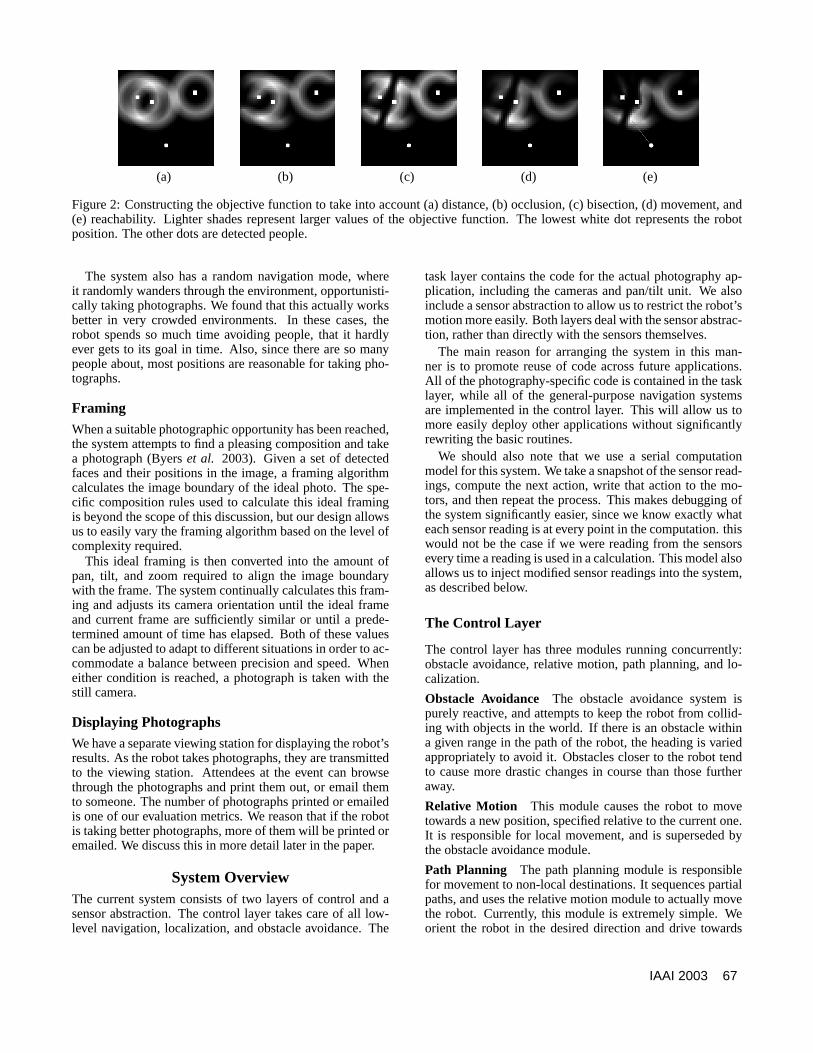
Figure 1: An overview of the photography system architec-ture.
types of photos.We feel that we should note that there is a lot of room
for improvement in the current system. Many of the algo-rithms are quite basic, and the performance of the systemwould be improved if they were improved or replaced. Webelieve it is useful to present the system in its current statebecause it illustrates the overall level of performance thatcan be achieved with very simple components working to-gether. When working on a mobile robot, there is also util-ity in using algorithms that are as computationally simple aspossible. Computation costs power, and can lead to signifi-cantly shorter battery lifetimes. We are, therefore, interestedin the simplest algorithm that we can get away with, even ifperformance is not quite as good.
Now that the basic system is in place we are finding that itis a good platform for general mobile robotics research. Thesystem is purposefully designed to be modular, so that moreadvanced algorithms can be easily added and evaluated. Italso provides a vehicle for research into areas not specifi-cally tied to the photography project, such as navigation andpath-planning. Our efforts are currently directed at evalu-ating the system, and the effects that adding more sophisti-cated algorithms will have, in terms of overall performance,battery life, responsiveness,etc.
Robot PhotographyWe have broken the task of photography into the followingsequential steps: locating potential subjects, selecting a pho-tographic opportunity, navigating to the opportunity, fram-ing and taking a shot, and displaying the final photograph.These are summarized in figure 1.
Locating Potential SubjectsIn order to locate potential subjects, we search for faces inthe images from the video camera. A common strategy inface detection is to use skin color to help isolate regions aspotential faces. Because skin occupies an easily definableregion in color space, we are able to define a look-up tablewhich maps from a color’s chromaticity to its likelihood ofbeing skin. Applying this function to each pixel of an imageallows us to construct a binary image representing each pixelas either skin or non-skin. We then segment this image intocontiguous regions with each region representing a potentialface.
The next step is to determine the size and relative locationin space of the object associated with each skin region in
the image. The pixel location of a region can be translatedinto a ray extending from the camera through the center ofthe object. This ray’s projection onto the ground plane canthen be associated with one of the 180 rays of laser data. Ifwe make the assumption that all perceived objects extend tothe floor, as is usually the case with the bodies associateswith faces, then this laser reading will tell us the horizontaldistance to the object. Knowing this distance allows us tocalculate the position in space and the absolute size of eachobject.
All regions whose geometric and spatial properties fallwithin the range of expected face sizes and heights are clas-sified as faces.
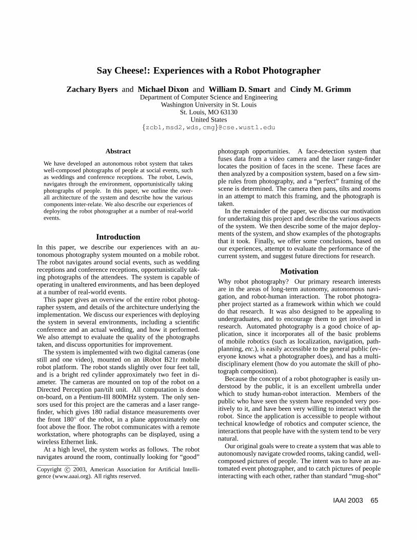
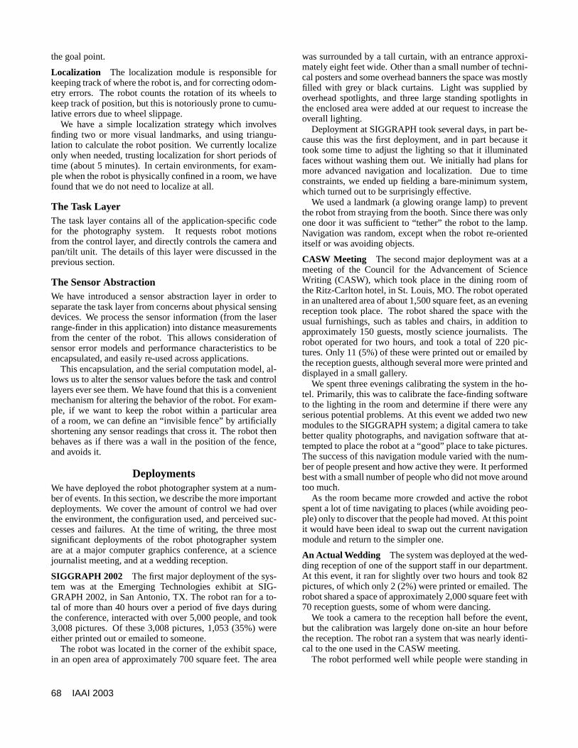
Selecting a Photographic OpportunityThe relative positions of potential photographic subjects arethen used to calculate the location of the best photographicopportunity. We discretize the floor plane into a grid withsquares 20cm on a side. For each grid square within a givenrange of the robot, we calculate the value of an objectivefunction that measures the potential quality of a photographtaken from that position. This objective function is calcu-lated using knowledge about good picture composition.
• The best pictures are taken between 4 and 7 feet from thesubject.
• One subject should not occlude another.
• Photographs should not be taken from the perpendicularbisector of two subjects.
• Positions that are closer to the current robot positionshould be preferred.
• If the direct path to a position is obstructed, that positionshould be less desirable.
These rules are encoded as parts of the objective function.For example, the first rule could be implemented by calcu-lating the distance,di, from the position under considera-tion to each person in the environment. This rule wouldthen contribute a value,v1, to the objective function, where
v1 =∑i exp
(− (d− 5.5)2
). There will be one such term,
vj , for each of the rules above, and the total value,v, is justthe sum of them,v =
∑5j=1 vj . This is illustrated in fig-
ure 2. Once we calculate values for all cells within a set dis-tance of the robot, we select the one with the highest valueas the next destination.
NavigationGiven a photographic opportunity, the system will attempt tomove the robot to the given destination while avoiding obsta-cles. If obstacles prevent the robot from traveling along theideal heading, a clear heading nearest to the ideal is choseninstead. The system continually reassesses the ideal head-ing, choosing either that or the closest clear heading untilthe desired position is achieved. After a specified number ofdeviations from the ideal heading, the robot will give up onthat photograph, preventing it from endlessly trying to reachan impossible position.
66 IAAI 2003
(a) (b) (c) (d) (e)
Figure 2: Constructing the objective function to take into account (a) distance, (b) occlusion, (c) bisection, (d) movement, and(e) reachability. Lighter shades represent larger values of the objective function. The lowest white dot represents the robotposition. The other dots are detected people.
The system also has a random navigation mode, whereit randomly wanders through the environment, opportunisti-cally taking photographs. We found that this actually worksbetter in very crowded environments. In these cases, therobot spends so much time avoiding people, that it hardlyever gets to its goal in time. Also, since there are so manypeople about, most positions are reasonable for taking pho-tographs.
FramingWhen a suitable photographic opportunity has been reached,the system attempts to find a pleasing composition and takea photograph (Byerset al. 2003). Given a set of detectedfaces and their positions in the image, a framing algorithmcalculates the image boundary of the ideal photo. The spe-cific composition rules used to calculate this ideal framingis beyond the scope of this discussion, but our design allowsus to easily vary the framing algorithm based on the level ofcomplexity required.
This ideal framing is then converted into the amount ofpan, tilt, and zoom required to align the image boundarywith the frame. The system continually calculates this fram-ing and adjusts its camera orientation until the ideal frameand current frame are sufficiently similar or until a prede-termined amount of time has elapsed. Both of these valuescan be adjusted to adapt to different situations in order to ac-commodate a balance between precision and speed. Wheneither condition is reached, a photograph is taken with thestill camera.
Displaying PhotographsWe have a separate viewing station for displaying the robot’sresults. As the robot takes photographs, they are transmittedto the viewing station. Attendees at the event can browsethrough the photographs and print them out, or email themto someone. The number of photographs printed or emailedis one of our evaluation metrics. We reason that if the robotis taking better photographs, more of them will be printed oremailed. We discuss this in more detail later in the paper.
System OverviewThe current system consists of two layers of control and asensor abstraction. The control layer takes care of all low-level navigation, localization, and obstacle avoidance. The
task layer contains the code for the actual photography ap-plication, including the cameras and pan/tilt unit. We alsoinclude a sensor abstraction to allow us to restrict the robot’smotion more easily. Both layers deal with the sensor abstrac-tion, rather than directly with the sensors themselves.
The main reason for arranging the system in this man-ner is to promote reuse of code across future applications.All of the photography-specific code is contained in the tasklayer, while all of the general-purpose navigation systemsare implemented in the control layer. This will allow us tomore easily deploy other applications without significantlyrewriting the basic routines.
We should also note that we use a serial computationmodel for this system. We take a snapshot of the sensor read-ings, compute the next action, write that action to the mo-tors, and then repeat the process. This makes debugging ofthe system significantly easier, since we know exactly whateach sensor reading is at every point in the computation. thiswould not be the case if we were reading from the sensorsevery time a reading is used in a calculation. This model alsoallows us to inject modified sensor readings into the system,as described below.
The Control Layer
The control layer has three modules running concurrently:obstacle avoidance, relative motion, path planning, and lo-calization.
Obstacle Avoidance The obstacle avoidance system ispurely reactive, and attempts to keep the robot from collid-ing with objects in the world. If there is an obstacle withina given range in the path of the robot, the heading is variedappropriately to avoid it. Obstacles closer to the robot tendto cause more drastic changes in course than those furtheraway.
Relative Motion This module causes the robot to movetowards a new position, specified relative to the current one.It is responsible for local movement, and is superseded bythe obstacle avoidance module.
Path Planning The path planning module is responsiblefor movement to non-local destinations. It sequences partialpaths, and uses the relative motion module to actually movethe robot. Currently, this module is extremely simple. Weorient the robot in the desired direction and drive towards
IAAI 2003 67
the goal point.
Localization The localization module is responsible forkeeping track of where the robot is, and for correcting odom-etry errors. The robot counts the rotation of its wheels tokeep track of position, but this is notoriously prone to cumu-lative errors due to wheel slippage.
We have a simple localization strategy which involvesfinding two or more visual landmarks, and using triangu-lation to calculate the robot position. We currently localizeonly when needed, trusting localization for short periods oftime (about 5 minutes). In certain environments, for exam-ple when the robot is physically confined in a room, we havefound that we do not need to localize at all.
The Task LayerThe task layer contains all of the application-specific codefor the photography system. It requests robot motionsfrom the control layer, and directly controls the camera andpan/tilt unit. The details of this layer were discussed in theprevious section.
The Sensor AbstractionWe have introduced a sensor abstraction layer in order toseparate the task layer from concerns about physical sensingdevices. We process the sensor information (from the laserrange-finder in this application) into distance measurementsfrom the center of the robot. This allows consideration ofsensor error models and performance characteristics to beencapsulated, and easily re-used across applications.
This encapsulation, and the serial computation model, al-lows us to alter the sensor values before the task and controllayers ever see them. We have found that this is a convenientmechanism for altering the behavior of the robot. For exam-ple, if we want to keep the robot within a particular areaof a room, we can define an “invisible fence” by artificiallyshortening any sensor readings that cross it. The robot thenbehaves as if there was a wall in the position of the fence,and avoids it.
DeploymentsWe have deployed the robot photographer system at a num-ber of events. In this section, we describe the more importantdeployments. We cover the amount of control we had overthe environment, the configuration used, and perceived suc-cesses and failures. At the time of writing, the three mostsignificant deployments of the robot photographer systemare at a major computer graphics conference, at a sciencejournalist meeting, and at a wedding reception.
SIGGRAPH 2002 The first major deployment of the sys-tem was at the Emerging Technologies exhibit at SIG-GRAPH 2002, in San Antonio, TX. The robot ran for a to-tal of more than 40 hours over a period of five days duringthe conference, interacted with over 5,000 people, and took3,008 pictures. Of these 3,008 pictures, 1,053 (35%) wereeither printed out or emailed to someone.
The robot was located in the corner of the exhibit space,in an open area of approximately 700 square feet. The area
was surrounded by a tall curtain, with an entrance approxi-mately eight feet wide. Other than a small number of techni-cal posters and some overhead banners the space was mostlyfilled with grey or black curtains. Light was supplied byoverhead spotlights, and three large standing spotlights inthe enclosed area were added at our request to increase theoverall lighting.
Deployment at SIGGRAPH took several days, in part be-cause this was the first deployment, and in part because ittook some time to adjust the lighting so that it illuminatedfaces without washing them out. We initially had plans formore advanced navigation and localization. Due to timeconstraints, we ended up fielding a bare-minimum system,which turned out to be surprisingly effective.
We used a landmark (a glowing orange lamp) to preventthe robot from straying from the booth. Since there was onlyone door it was sufficient to “tether” the robot to the lamp.Navigation was random, except when the robot re-orienteditself or was avoiding objects.
CASW Meeting The second major deployment was at ameeting of the Council for the Advancement of ScienceWriting (CASW), which took place in the dining room ofthe Ritz-Carlton hotel, in St. Louis, MO. The robot operatedin an unaltered area of about 1,500 square feet, as an eveningreception took place. The robot shared the space with theusual furnishings, such as tables and chairs, in addition toapproximately 150 guests, mostly science journalists. Therobot operated for two hours, and took a total of 220 pic-tures. Only 11 (5%) of these were printed out or emailed bythe reception guests, although several more were printed anddisplayed in a small gallery.
We spent three evenings calibrating the system in the ho-tel. Primarily, this was to calibrate the face-finding softwareto the lighting in the room and determine if there were anyserious potential problems. At this event we added two newmodules to the SIGGRAPH system; a digital camera to takebetter quality photographs, and navigation software that at-tempted to place the robot at a “good” place to take pictures.The success of this navigation module varied with the num-ber of people present and how active they were. It performedbest with a small number of people who did not move aroundtoo much.
As the room became more crowded and active the robotspent a lot of time navigating to places (while avoiding peo-ple) only to discover that the people had moved. At this pointit would have been ideal to swap out the current navigationmodule and return to the simpler one.
An Actual Wedding The system was deployed at the wed-ding reception of one of the support staff in our department.At this event, it ran for slightly over two hours and took 82pictures, of which only 2 (2%) were printed or emailed. Therobot shared a space of approximately 2,000 square feet with70 reception guests, some of whom were dancing.
We took a camera to the reception hall before the event,but the calibration was largely done on-site an hour beforethe reception. The robot ran a system that was nearly identi-cal to the one used in the CASW meeting.
The robot performed well while people were standing in
68 IAAI 2003
the buffet line, but after this the lights were lowered and wehad to re-calibrate the system again. At this point, most peo-ple were sitting so there were few potential shots. Then thelighting was lowered again for dancing, and the face-findingsystem was unable to function at those lighting levels.
SuccessesThe modules that are least susceptible to environmentchanges are the low-level people-avoidance routines, cameracontrol, image-capture communication, and the random nav-igation. Framing shots is also fairly robust, provided the facedetection algorithm is functioning. The localization systemworked well in the SIGGRAPH environment, but was notneeded at the other events, because of the configuration ofthe environment. Random navigation worked surprisinglywell in crowded situations.
FailuresThe most fragile component of the system is face-finding,which is highly dependent on the color and intensity of thelights and the background wall colors. In most environmentswe had very little control over the lighting. Even at SIG-GRAPH we were constrained to use the types of lights theycould provide us, although we could position them wherewe wanted to.
The other area where we had variable success was high-level navigation. Our two navigation strategies perform bestin different environments — crowded versus sparse. Atthe CASW event and the wedding the number of peoplechanged throughout the evening. In this case it would havebeen very useful to be able to automatically swap navigationstrategies depending on the situation.
EvaluationA system like the robot photographer is inherently hard toevaluate. Most natural characterizations of performanceare highly subjective. We also know of no similar systemwith which to compare ours. Based on the performance atSIGGRAPH, approximately one third of the pictures thatthe robot takes are at least good enough to qualify as sou-venirs. This agrees with some recent evaluations we havebegun. People were asked to classify randomly-selectedphotographs from the robot’s portfolio as either “very bad”,“bad”, “neutral”, “good”, or “very good”. Roughly one thirdof the photographs were classified as “good” or “very good”.While this is certainly not conclusive, we believe that it isencouraging, especially given the early stage of the overallsystem.
We are currently planning more extensive evaluations.These include double-blind studies, where some human-taken photographs will be randomly mixed in with therobot’s to see if people have a significant preference. Wealso plan evaluations by subjects who do not know a robottook the photographs, to see if there is a bias in our currentresults.
Conclusions and Further WorkSeveral other robots have been fielded in similar real-worlddeployments. For example, Minerva gave tours of the
Smithsonian Museum of American History over a period of14 days (Burgardet al. 1999). This is certainly a longerdeployment than we have had, with a similar level of en-vironmental complexity. Other robots have been deployedfor longer, but generally with much simpler tasks and envi-ronments (Hada & Yuta 2000). Another notable long-termdeployment involves a robot that provides assistance for el-derly persons (Montemerloet al. 2002), which included sev-eral day-long deployments.
Although each of these robot systems has proven verysuccessful, they all share something in common. They areall designed for a single environment, or for a very simi-lar set of environments. This allows them to be optimizedfor that particular task. We believe that our experiences in arange of widely different indoor environments adds a dimen-sion that this previous work does not address: the beginningsof general design principles for a robot system that must bedeployed across several different environments.
Our robot photography system is still very much a work-in-progress. However, based on a number of real-world de-ployments, we believe that there are a few general designrules that can be extracted from our experiences. Thesespecifically apply to the design and implementation of anautonomous mobile robot system that must accomplish acomplex task in an unaltered environment, while still beingportable to other environments. More details of the system,and example photographs, are available on the project website athttp://www.cse.wustl.edu/ ∼lewis .
Adaptable to the Environment The complexity that anysuccessful robot system must deal with is a combination ofthe complexities of both the task and the environment. Evensimple tasks can be hard to accomplish in complex environ-ments. Although we have control over the task complexity,we often have little or no control over the environment.
Even simple environments, such as our SIGGRAPH de-ployment, can have hidden complexities. These are almostimpossible to predict with accuracy ahead of time. This ar-gues for a software architecture that can be altered easily atthe site of the deployment. Since we really do not want tobe writing and compiling code on-site, we would like thatsystem to be composed of relatively small modules that canbe combined as necessary to get everything working.
Our experiences also argue for using as simple a systemas possible to accomplish the task. Any complete robot sys-tem is, by definition, a complex collection of software thatmust all work at the same time. The fewer elements that arepresent, the less there is to go wrong.
Highly Modular Framework On-site customization ismuch easier if the system is designed to be highly modu-lar. It also allows it to be more readily expandable, as newsensors and algorithms become available. More importantly,however, it allows new experimental modules to be easilyadded to the system and evaluated. For example, a studentworking on a new navigation algorithm can add it to the sys-tem, and quickly be able to evaluate it against all of the cur-rent strategies, in the context of a whole application.
Being highly modular also suggests an incremental designstrategy. As new problems crop up due to new environmen-
IAAI 2003 69
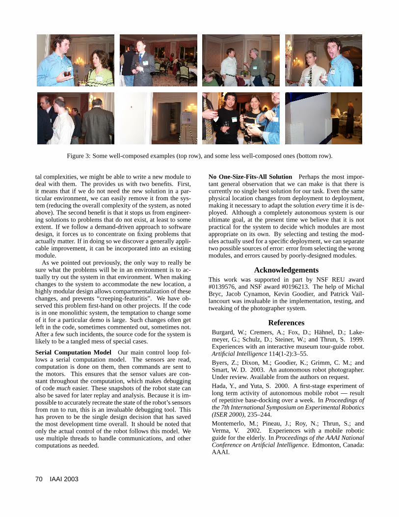
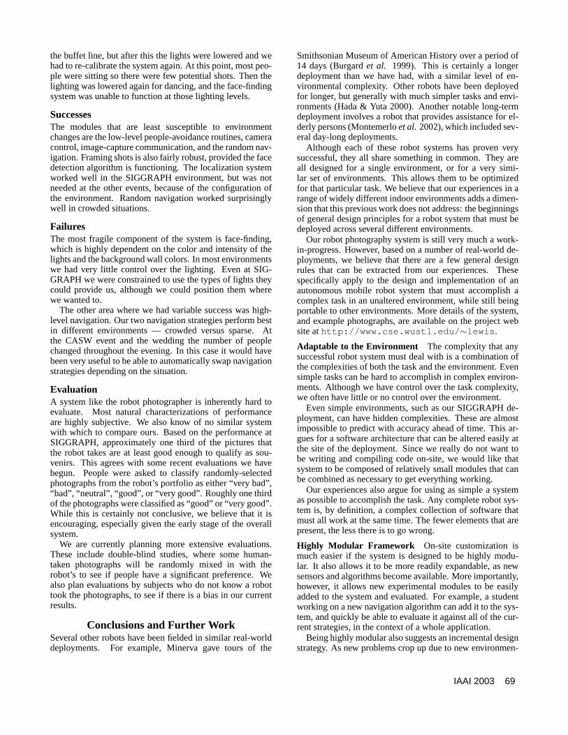
Figure 3: Some well-composed examples (top row), and some less well-composed ones (bottom row).
tal complexities, we might be able to write a new module todeal with them. The provides us with two benefits. First,it means that if we do not need the new solution in a par-ticular environment, we can easily remove it from the sys-tem (reducing the overall complexity of the system, as notedabove). The second benefit is that it stops us from engineer-ing solutions to problems that do not exist, at least to someextent. If we follow a demand-driven approach to softwaredesign, it forces us to concentrate on fixing problems thatactually matter. If in doing so we discover a generally appli-cable improvement, it can be incorporated into an existingmodule.
As we pointed out previously, the only way to really besure what the problems will be in an environment is to ac-tually try out the system in that environment. When makingchanges to the system to accommodate the new location, ahighly modular design allows compartmentalization of thesechanges, and prevents “creeping-featuritis”. We have ob-served this problem first-hand on other projects. If the codeis in one monolithic system, the temptation to change someof it for a particular demo is large. Such changes often getleft in the code, sometimes commented out, sometimes not.After a few such incidents, the source code for the system islikely to be a tangled mess of special cases.
Serial Computation Model Our main control loop fol-lows a serial computation model. The sensors are read,computation is done on them, then commands are sent tothe motors. This ensures that the sensor values are con-stant throughout the computation, which makes debuggingof codemucheasier. These snapshots of the robot state canalso be saved for later replay and analysis. Because it is im-possible to accurately recreate the state of the robot’s sensorsfrom run to run, this is an invaluable debugging tool. Thishas proven to be the single design decision that has savedthe most development time overall. It should be noted thatonly the actual control of the robot follows this model. Weuse multiple threads to handle communications, and othercomputations as needed.
No One-Size-Fits-All Solution Perhaps the most impor-tant general observation that we can make is that there iscurrently no single best solution for our task. Even the samephysical location changes from deployment to deployment,making it necessary to adapt the solutioneverytime it is de-ployed. Although a completely autonomous system is ourultimate goal, at the present time we believe that it is notpractical for the system to decide which modules are mostappropriate on its own. By selecting and testing the mod-ules actually used for a specific deployment, we can separatetwo possible sources of error: error from selecting the wrongmodules, and errors caused by poorly-designed modules.
AcknowledgementsThis work was supported in part by NSF REU award#0139576, and NSF award #0196213. The help of MichalBryc, Jacob Cynamon, Kevin Goodier, and Patrick Vail-lancourt was invaluable in the implementation, testing, andtweaking of the photographer system.
ReferencesBurgard, W.; Cremers, A.; Fox, D.; Hahnel, D.; Lake-meyer, G.; Schulz, D.; Steiner, W.; and Thrun, S. 1999.Experiences with an interactive museum tour-guide robot.Artificial Intelligence114(1-2):3–55.Byers, Z.; Dixon, M.; Goodier, K.; Grimm, C. M.; andSmart, W. D. 2003. An autonomous robot photographer.Under review. Available from the authors on request.Hada, Y., and Yuta, S. 2000. A first-stage experiment oflong term activity of autonomous mobile robot — resultof repetitive base-docking over a week. InProceedings ofthe 7th International Symposium on Experimental Robotics(ISER 2000), 235–244.Montemerlo, M.; Pineau, J.; Roy, N.; Thrun, S.; andVerma, V. 2002. Experiences with a mobile roboticguide for the elderly. InProceedings of the AAAI NationalConference on Artificial Intelligence. Edmonton, Canada:AAAI.
70 IAAI 2003