sba accumulator safety blocks -...
TRANSCRIPT

Catalog HY10-1630/USIntroduction
Parker HannifinGlobal Accumulator DivisionUnited States85
OverviewSBA Accumulator Safety Blocks
IN THIS SECTIONOverview 85
Technical Data 87
Models & Dimensions
SBA10 89
SBA20 90
SBA32 91
SBAT3L 92
SBAT3P 93
Adapters 94
Ordering Information 96
SBA Accumulator Safety BlocksFor working pressures up to 350 Bar (5075 PSI)
SB
A S
afet
y B
lock
s
Features• Available in 3 Sizes• SAE and BSPP Porting• CE Certified Relief Valve• Lockout/Tagout Optional• Buna or Fluorocarbon Seals• Electrical Discharge Option
Catalog HY10-1630/USIntroduction
Parker HannifinGlobal Accumulator DivisionUnited States86
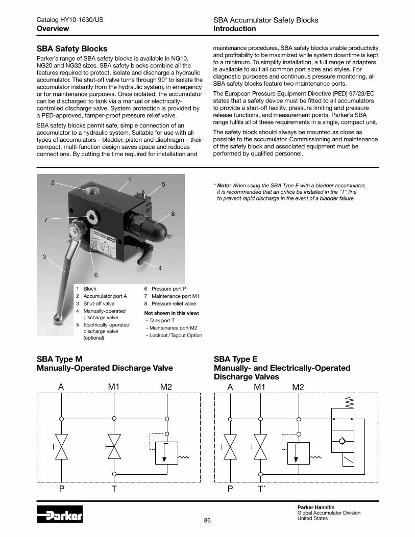
1 Block
2 Accumulator port A
3 Shut-off valve
4 Manually-operated discharge valve
5 Electrically-operated discharge valve (optional)
6 Pressure port P
7 Maintenance port M1
8 Pressure relief valve
Not shown in this view: – Tank port T
– Maintenance port M2
– Lockout /Tagout Option
OverviewSBA Accumulator Safety Blocks
SBA Safety BlocksParker’s range of SBA safety blocks is available in NG10, NG20 and NG32 sizes. SBA safety blocks combine all the features required to protect, isolate and discharge a hydraulic accumulator. The shut-off valve turns through 90° to isolate the accumulator instantly from the hydraulic system, in emergency or for maintenance purposes. Once isolated, the accumulator can be discharged to tank via a manual or electrically-controlled discharge valve. System protection is provided by a PED-approved, tamper-proof pressure relief valve.
SBA safety blocks permit safe, simple connection of an accumulator to a hydraulic system. Suitable for use with all types of accumulators – bladder, piston and diaphragm – their compact, multi-function design saves space and reduces connections. By cutting the time required for installation and
maintenance procedures, SBA safety blocks enable productivity and profitability to be maximized while system downtime is kept to a minimum. To simplify installation, a full range of adapters is available to suit all common port sizes and styles. For diagnostic purposes and continuous pressure monitoring, all SBA safety blocks feature two maintenance ports.
The European Pressure Equipment Directive (PED) 97/23/EC states that a safety device must be fitted to all accumulators to provide a shut-off facility, pressure limiting and pressure release functions, and measurement points. Parker’s SBA range fulfils all of these requirements in a single, compact unit.
The safety block should always be mounted as close as possible to the accumulator. Commissioning and maintenance of the safety block and associated equipment must be performed by qualified personnel.
12
4
3
6
7 8
5
SBA Type E Manually- and Electrically-Operated Discharge Valves
SBA Type M Manually-Operated Discharge Valve
A M1 M2
P T
A M1 M2
P T
* Note: When using the SBA Type E with a bladder accumulator, it is recommended that an orifice be installed in the "T" line to prevent rapid discharge in the event of a bladder failure.
*
Catalog HY10-1630/US
Parker HannifinGlobal Accumulator DivisionUnited States87
SBA Accumulator Safety BlocksSBA SeriesTechnical Data
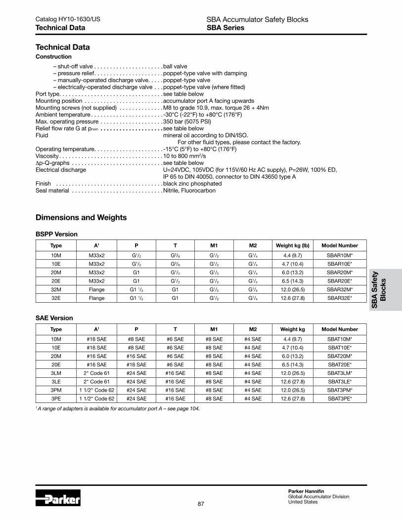
1 A range of adapters is available for accumulator port A – see page 104.
Technical DataConstruction
– shut-off valve . . . . . . . . . . . . . . . . . . . . . .ball valve – pressure relief. . . . . . . . . . . . . . . . . . . . . .poppet-type valve with damping – manually-operated discharge valve. . . . .poppet-type valve – electrically-operated discharge valve . . .poppet-type valve (where fitted)Port type. . . . . . . . . . . . . . . . . . . . . . . . . . . . . . . . .see table belowMounting position . . . . . . . . . . . . . . . . . . . . . . . . .accumulator port A facing upwardsMounting screws (not supplied) . . . . . . . . . . . . . .M8 to grade 10.9, max. torque 26 + 4NmAmbient temperature . . . . . . . . . . . . . . . . . . . . . . . -30°C (-22°F) to +80°C (176°F)Max. operating pressure . . . . . . . . . . . . . . . . . . . .350 bar (5075 PSI)Relief flow rate G at pnom . . . . . . . . . . . . . . . . . . . .see table belowFluid mineral oil according to DIN/ISO. For other fluid types, please contact the factory.Operating temperature. . . . . . . . . . . . . . . . . . . . . . -15°C (5°F) to +80°C (176°F)Viscosity . . . . . . . . . . . . . . . . . . . . . . . . . . . . . . . . .10 to 800 mm2/s∆p-Q-graphs . . . . . . . . . . . . . . . . . . . . . . . . . . . . .see table belowElectrical discharge U=24VDC, 105VDC (for 115V/60 Hz AC supply), P=26W, 100% ED, IP 65 to DIN 40050, connector to DIN 43650 type AFinish . . . . . . . . . . . . . . . . . . . . . . . . . . . . . . . . . .black zinc phosphatedSeal material . . . . . . . . . . . . . . . . . . . . . . . . . . . . .Nitrile, Fluorocarbon
Type A1 P T M1 M2 Weight kg (lb) Model Number
10M M33x2 G1/2 G3/8 G1/2 G1/4 4.4 (9.7) SBAR10M*
10E M33x2 G1/2 G3/8 G1/2 G1/4 4.7 (10.4) SBAR10E*
20M M33x2 G1 G1/2 G1/2 G1/4 6.0 (13.2) SBAR20M*
20E M33x2 G1 G1/2 G1/2 G1/4 6.5 (14.3) SBAR20E*
32M Flange G1 1/2 G1 G1/2 G1/4 12.0 (26.5) SBAR32M*
32E Flange G1 1/2 G1 G1/2 G1/4 12.6 (27.8) SBAR32E*
Type A1 P T M1 M2 Weight kg Model Number
10M #16 SAE #8 SAE #6 SAE #8 SAE #4 SAE 4.4 (9.7) SBAT10M*
10E #16 SAE #8 SAE #6 SAE #8 SAE #4 SAE 4.7 (10.4) SBAT10E*
20M #16 SAE #16 SAE #6 SAE #8 SAE #4 SAE 6.0 (13.2) SBAT20M*
20E #16 SAE #16 SAE #6 SAE #8 SAE #4 SAE 6.5 (14.3) SBAT20E*
3LM 2" Code 61 #24 SAE #16 SAE #8 SAE #4 SAE 12.0 (26.5) SBAT3LM*
3LE 2" Code 61 #24 SAE #16 SAE #8 SAE #4 SAE 12.6 (27.8) SBAT3LE*
3PM 1 1/2" Code 62 #24 SAE #16 SAE #8 SAE #4 SAE 12.0 (26.5) SBAT3PM*
3PE 1 1/2" Code 62 #24 SAE #16 SAE #8 SAE #4 SAE 12.6 (27.8) SBAT3PE*
SAE Version
Dimensions and Weights
BSPP Version
SB
A S
afet
y B
lock
s

Catalog HY10-1630/US
Parker HannifinGlobal Accumulator DivisionUnited States88
SBA Accumulator Safety BlocksSBA SeriesTechnical Data
Pressure Relief ValveThe function of the pressure relief valve is to protect the accumulator in service. If pressure exceeds the relief valve setting, the valve lifts off its seat and fluid is discharged to tank, allowing pressure in the system to fall to a safe level.
Because of its cartridge design, the pressure relief valve can be readily replaced by a valve with a different pressure setting, selected from the table. A new approval under PED 97/23/EC is not required following this change. The pre-set relief pressure, in bar, is stamped onto the identification plate.
Type ApprovalThe pressure relief valve is checked and securely sealed following approval, according to pressure vessel regulations. It carries a CE mark, type approval number and serial number. All valves are supplied with a certificate
showing the pressure setting. The documents supplied with the pressure relief valve must be retained by the manufacturer, as they will be required in the event of repeat tests.
Manual and Electrical Discharge ValvesThe discharge valve allows fluid stored in the accumulator to be discharged to tank. All models of SBA safety block are fitted with a manually-operated discharge valve. As an optional feature, an electrical discharge valve is available in addition to the manual valve. An electrical discharge valve should be specified where the safety block is to be mounted in a remote or inaccessible location. Manual-only versions of the SBA safety block are denoted by an M in the model code, see page 96, while models with both a manual and an electrical discharge valve are designated E.
0123456789
10
0 50(12.5)
100(25)
150(37.5)
200(50)
Q l/min (g/min)
Δp
bar psi
145131116102877358442915
0123456789
10
Δp
bar psi
0 50(12.5)
200(50)
300 (75)
400(100)
Q l/min (g/min)
500(125)
145131116102877358442915
0123456789
10
Δp
bar psi
0 100(25)
200(50)
300 (75)
400(100)
Q l/min (gpm)
500(125)
145131116102877358442915
0123456789
10
Δp
bar psi
0 100(25)
200(50)
300 (75)
400(100)
Q l/min (gpm)
500(125)
145131116102877358442915
0
50
100
150
200
250
300
350
400
0 10(2.5)
20(5)
30(7.5)
40(10)
50(12.5)
60(15)
70(17.5)
80(20)
90(22.5)
100(25)
110(27.5)
120(30)
Δp
bar psi
Q l/min (gpm)
5800
5075
4350
3625
2900
2175
1450
725
0
50
100
150
200
250
300
350
400
0 10(2.5)
20(5)
30(7.5)
40(10)
50(12.5)
60(15)
70(17.5)
80(20)
90(22.5)
100(25)
110(27.5)
120(30)
Δp
bar psi
Q l/min (gpm)
5800
5075
4350
3625
2900
2175
1450
725
Flow – Accumulator (A) to Pressure Port (P)
Flow Limits for Safety Valve SV – All Models
SBA10
SBA20
SBA32, 3L, 3P
Pressure p bar (PSI) Item Number
50 (725) SV050
70 (1015) SV070
100 (1450) SV100
120 (1740) SV120
140 (2030) SV140
160 (2320) SV160
200 (2900) SV200
210 (3045) SV210
250 (3625) SV250
280 (4060) SV280
300 (4350) SV300
330 (4785) SV330
Pressure Settings

Catalog HY10-1630/US
Parker HannifinGlobal Accumulator DivisionUnited States89
SBA Accumulator Safety BlocksSBA10Models & Dimensions
25.0
(1.0
)
51.0
(2.0
)
120.
0 (4
.7)
190
(7.5
) max
Handle radius of swing (Handle shown in closed position)
28.0(1.1)
93.0(3.7)
21.7(0.9)
125 (4.9) max
17.0 (0.7)
28.0 (1.1)
20.0
(0.8
)
26.5
(1
.0) 10
5 (4
.1) m
ax
53.0
(2.1
)4.
0(0
.2)
25.0
(1.0
)
25.0
(1.0
)
104.
0 (4
.1)
8.0
(0.3
)
110
(4.3
) max
55.5(2.2)
50.0(2.0)
40.0(1.6)
Ø9.
0 (x
2)[(Ø
0.4
(x2)
]
Manual discharge valve
Pressure relief valve
79.0
(3.1
)
7.0
(0.3
)
35.0 (1.4)
31.25(1.2)
(20.0)(0.8)
26.5(1.0)
25.0
(1.0
)
25.0
(1.0
)
51.0
(2.0
)
120.
0 (4
.7)
190
(7.5
) max
Handle radius of swing (Handle shown in closed position)
28.0(1.1)
93.0(3.7)
21.7(0.9)
125 (4.9) max
17.0 (0.7)
28.0 (1.1)
20.0
(0.8
)
26.5
(1
.0) 10
5 (4
.1) m
ax
53.0
(2.1
)4.
0(0
.2)
25.0
(1.0
)
25.0
(1.0
)
104.
0 (4
.1)
8.0
(0.3
)
110
(4.3
) max
55.5(2.2)
50.0(2.0)
40.0(1.6)
Ø9.
0 (x
2)[(Ø
0.4
(x2)
]
Manual discharge valve
Pressure relief valve
79.0
(3.1
)
7.0
(0.3
)
35.0 (1.4)
31.25(1.2)
(20.0)(0.8)
26.5(1.0)
25.0
(1.0
)
All dimensions are in millimeters (inches).
Reference Dimensions – SBAR10 and SBAT10
Han
dle
rad
ius
of s
win
g (H
and
le s
how
n in
clo
sed
pos
itio
n)
Optional Electric Discharge Valve
Man
ual d
isch
arge
va
lve
Pre
ssur
e re
lief
valv
e
G1/
2 (B
SP
)
Shu
t-o
ff v
alve
25.0
(1
.0)
51.0
(2.0
)12
0.0
(4.7
)
190
(7.5
) max
125 (4.9) max
28.0(1.1)
93.0(3.7)
21.7(0.9)
25.0
(1.0
)
110
(4.3
) max
79.0
(3.1
)
7.0
(0.3
)
35.0(1.4)
31.25(1.2)
(20.0)(0.8)
8.0
(0.3
)
50.0(2.0)
40.0(1.6)
56.5(2.2)
25.0
(1.0
)
104.
0 (4
.1)
79.0
(3.1
)
26.5(1.0)
55.5(2.2)
28.0(1.1)
26.5
(1.0
)
163
(6.4
) max
163 (6.4) max
53.0
(2
.1)
65 (2
.6) m
ax
20.0
(0.8
)
17.0(0.7)
Electrical discharge valve
Connector to EN 175301-803(DIN 43650/ISO 4400 Type A)
SB
A S
afet
y B
lock
s
25.0
(1.0
)
51.0
(2.0
)
120.
0 (4
.7)
190
(7.5
) max
Handle radius of swing (Handle shown in closed position)
28.0(1.1)
93.0(3.7)
21.7(0.9)
125 (4.9) max
17.0 (0.7)
28.0 (1.1)
20.0
(0.8
)
26.5
(1
.0) 10
5 (4
.1) m
ax
53.0
(2.1
)4.
0(0
.2)
25.0
(1.0
)
25.0
(1.0
)
104.
0 (4
.1)
8.0
(0.3
)
110
(4.3
) max
55.5(2.2)
50.0(2.0)
40.0(1.6)
Ø9.
0 (x
2)[(Ø
0.4
(x2)
]
Manual discharge valve
Pressure relief valve
79.0
(3.1
)
7.0
(0.3
)
35.0 (1.4)
31.25(1.2)
(20.0)(0.8)
26.5(1.0)
25.0
(1.0
)
119.30(4.7)
226.94(8.9)
101.96(4.0)
Outer Lock Plate to be oriented as shown relative to the handle (Handle is shown in closed position) typical all series
NOTE: Lockout/Tagout device is provided as an option

Catalog HY10-1630/US
Parker HannifinGlobal Accumulator DivisionUnited States90
28.0(1.1)
93.0(3.7)
31.2(1.2)
125 (5.0) max
165
(6.5
) max
30.0
(1.2
)62
.0(2
.4)
130.
0(5
.1)
200
(7.9
) max
Handle radius of swing (Handle shown in closed position)
Shut-off valve
17.0(0.7)
28.0(1.1)
21.5
(0.8
)
36.5
(1.4
)
135
(5.3
)max
63.0
(2.5
)4.
0(0
.2)
30.5(1.2)
30.0
(1.2
)
30.0
(1.2
)
30.0
(1.2
)
114.
0 (4
.5)
8.0
(0.3
)
55.5(2.2)
34.0(1.3)
32.0(1.3)
Ø9.
0 (x
2)[Ø
0.4
(x2)
]
89.0
(3.5
)
7.0
(0.3
)
39.5(1.6)
30.6(1.2)
21.5(0.8)
Manual discharge valve
Pressure relief valve
28.0(1.1)
93.0(3.7)
31.2(1.2)
125 (5.0) max
165
(6.5
) max
30.0
(1.2
)62
.0(2
.4)
130.
0(5
.1)
200
(7.9
) max
Handle radius of swing (Handle shown in closed position)
Shut-off valve
17.0(0.7)
28.0(1.1)
21.5
(0.8
)
36.5
(1.4
)
135
(5.3
)max
63.0
(2.5
)4.
0(0
.2)
30.5(1.2)
30.0
(1.2
)
30.0
(1.2
)
30.0
(1.2
)
114.
0 (4
.5)
8.0
(0.3
)
55.5(2.2)
34.0(1.3)
32.0(1.3)
Ø9.
0 (x
2)[Ø
0.4
(x2)
]
89.0
(3.5
)
7.0
(0.3
)
39.5(1.6)
30.6(1.2)
21.5(0.8)
Manual discharge valve
Pressure relief valve
G1
(BS
P)
28.0(1.1)
93.0(3.7)
31.2(1.2)
125 (4.9) max
200
(7.9
) max
30.0
(1.2
)
62.0
(2.4
)
130.
0(5
.1)
195
(7.7
) max
195 (7.7) max
Han
dle
rad
ius
of s
win
g (H
and
le s
how
n in
clo
sed
pos
itio
n)
Shu
t-o
ff
valv
e
30.0
(1.2
)
89.0
(3.5
)
7.0
(0.3
)
39.5(1.6)
30.6(1.2)
(21.5)(0.9)
17.0(0.7)
28.0(1.1)
21.5
(0.8
)
36.5
(1.4
) 63.0
(2.5
)65
(2.6
) max
Man
ual
dis
char
ge v
alve
Pre
ssur
e re
lief v
alve
30.0
(1.2
)
114.
0 (4
.5)
8.0
(0.3
)
55.5(2.2)
34.0(1.3)
53.0(2.1)
Ø9.
0 (x
2)[(Ø
0.4)
(x2
)]
32.0(1.3)
165
(6.5
) max
30.5(1.2)
Ele
ctric
al
dis
char
ge
valv
e
Electrical discharge valve
Co
nnec
tor
to E
N 1
7530
1-80
3(D
IN 4
3650
/IS
O 4
400
Typ
e A
)
Connector to EN 175301-803(DIN 43650/ISO 4400 Type A)
89.0
(3.5
)
Optional Electric Discharge Valve
SBA Accumulator Safety BlocksModels & Dimensions SBA20
All dimensions are in millimeters (inches).
Reference Dimensions – SBAR20 and SBAT20
30.60(1.2)
68.50(2.7)
126.46(5.0)
124.00(4.9)
236.60(9.3)
Outer Lock Plate to be oriented as shown relative to the handle (Handle is shown in closed position) typical all series
NOTE: Lockout/Tagout device is provided as an option
Catalog HY10-1630/US
Parker HannifinGlobal Accumulator DivisionUnited States91
Handle radius of swing (Handle shown in closed position)
Shut-off valve
Manual discharge valve
Pressure relief valve
18.0(0.7)
108.0(4.3)
40.0(1.6)
155 (6.1) max
265
(10.
4) m
ax
50.0
(2.0
)
150.
0(5
.9)
17.0(0.7)
46.5
(1.8
)
58.0
(2.3
)
185
(7.3
)max
108.
0(4
.3)
28.0(1.1)
50.0
(2.0
)
38.0(1.5)
32.0(1.3)
Ø10
.0 (x
2)(Ø
0.4)
(x2)
130.
0(5
.1)
10.0
(0.4
)
60.0(2.4)
50.0
(2.0
)
117.
0(4
.6)
7.0
(0.3
)71.0(2.8)
62.0(2.4)
(46.5)(1.8)
215
(8.5
) max
Ø30
.0(Ø
1.2)
Ø10
5.0
(Ø4.
1)
50.0
(2.0
)
45.0
°
58.0(2.3)
M16 x 2 - 6H (x4) thread depth 22.5 min
50.0
(2.0
)109.
0 (4
.3)
Man
ual
dis
char
ge v
alve
G11 /
2 (B
SP
)
Han
dle
rad
ius
of s
win
g (H
and
le s
how
n in
clo
sed
pos
itio
n)
Shu
t-o
ff
valv
e
18.0(0.7)
108.0(4.3)
40.0(1.6)
155 (4.5) max
265
(10.
4) m
ax
50
.0(2
.0)
150.
0 (6
.0)
17.0(0.7)
46.5
(1.4
)
58.0
(2.3
)
250
(9.8
) max
250 (9.8) max
108.
0(4
.3)
28.0(1.1)
65 m
ax(2
.6)
50.0
(2.0
)11
7.0
(4.6
)
7.0
(0.3
)
71.0(2.8)
62.0(2.4)
46.5(1.8)
215
(8.5
) max
Ø30
.0(Ø
1.2)
Ø10
5.0
(Ø4.
1)
50.0
(2.0
)
45.0
°
58.0(2.3)
M16
x 2
- 6
H (x
4)
thre
ad d
epth
22
.5 m
in
Man
ual
dis
char
ge v
alve
Pre
ssur
e re
lief v
alve
38.0(1.5)32.0(1.3)
Ø10
.0 (x
2)(Ø
0.4)
(x2)
130.
0(5
.1)
10.0
(0.4
)
54.0(2.1)
60.0(2.4)
Ele
ctric
al
dis
char
ge
valv
e
Electrical discharge valve
Co
nnec
tor
to E
N 1
7530
1-80
3(D
IN 4
3650
/IS
O 4
400
Typ
e A
)
Connector to EN 175301-803(DIN 43650/ISO 4400 Type A)
Optional Electric Discharge Valve
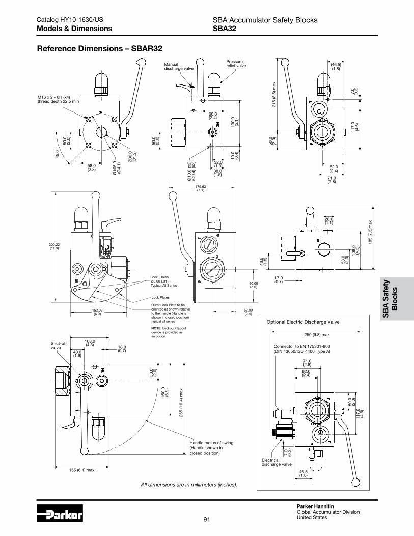
SBA Accumulator Safety BlocksSBA32Models & Dimensions
Handle radius of swing (Handle shown in closed position)
Shut-off valve
Manual discharge valve
Pressure relief valve
18.0(0.7)
108.0(4.3)
40.0(1.6)
155 (6.1) max
265
(10.
4) m
ax
50.0
(2.0
)
150.
0(5
.9)
17.0(0.7)
46.5
(1.8
)
58.0
(2.3
)
185
(7.3
)max
108.
0(4
.3)
28.0(1.1)
50.0
(2.0
)
38.0(1.5)
32.0(1.3)
Ø10
.0 (x
2)(Ø
0.4)
(x2)
130.
0(5
.1)
10.0
(0.4
)
60.0(2.4)
50.0
(2.0
)
117.
0(4
.6)
7.0
(0.3
)
71.0(2.8)
62.0(2.4)
(46.5)(1.8)
215
(8.5
) max
Ø30
.0(Ø
1.2)
Ø10
5.0
(Ø4.
1)
50.0
(2.0
)
45.0
°
58.0(2.3)
M16 x 2 - 6H (x4) thread depth 22.5 min
Handle radius of swing (Handle shown in closed position)
Shut-off valve
Manual discharge valve
Pressure relief valve
18.0(0.7)
108.0(4.3)
40.0(1.6)
155 (6.1) max
265
(10.
4) m
ax
50.0
(2.0
)
150.
0(5
.9)
17.0(0.7)
46.5
(1.8
)
58.0
(2.3
)
185
(7.3
)max
108.
0(4
.3)
28.0(1.1)
50.0
(2.0
)38.0(1.5)
32.0(1.3)
Ø10
.0 (x
2)(Ø
0.4)
(x2)
130.
0(5
.1)
10.0
(0.4
)
60.0(2.4)
50.0
(2.0
)
117.
0(4
.6)
7.0
(0.3
)
71.0(2.8)
62.0(2.4)
(46.5)(1.8)
215
(8.5
) max
Ø30
.0(Ø
1.2)
Ø10
5.0
(Ø4.
1)
50.0
(2.0
)
45.0
°
58.0(2.3)
M16 x 2 - 6H (x4) thread depth 22.5 min
Reference Dimensions – SBAR32
All dimensions are in millimeters (inches).
Handle radius of swing (Handle shown in closed position)
Shut-off valve
Manual discharge valve
Pressure relief valve
18.0(0.7)
108.0(4.3)
40.0(1.6)
155 (6.1) max
265
(10.
4) m
ax
50.0
(2.0
)
150.
0(5
.9)
17.0(0.7)
46.5
(1.8
)
58.0
(2.3
)
185
(7.3
)max
108.
0(4
.3)
28.0(1.1)
50.0
(2.0
)
38.0(1.5)
32.0(1.3)
Ø10
.0 (x
2)(Ø
0.4)
(x2)
130.
0(5
.1)
10.0
(0.4
)
60.0(2.4)
50.0
(2.0
)
117.
0(4
.6)
7.0
(0.3
)
71.0(2.8)
62.0(2.4)
(46.5)(1.8)
215
(8.5
) max
Ø30
.0(Ø
1.2)
Ø10
5.0
(Ø4.
1)
50.0
(2.0
)
45.0
°58.0(2.3)
M16 x 2 - 6H (x4) thread depth 22.5 min
SB
A S
afet
y B
lock
s
62.00(2.4)
90.00(3.5)
179.63(7.1)
Lock HolesØ8.00 (.31)Typical All Series
Lock Plates
152.02(6.0)
300.22(11.8)
Outer Lock Plate to be oriented as shown relative to the handle (Handle is shown in closed position) typical all series
NOTE: Lockout/Tagout device is provided as an option

Catalog HY10-1630/US
Parker HannifinGlobal Accumulator DivisionUnited States92
SBA Accumulator Safety BlocksSBAT3L Models & Dimensions
All dimensions are in millimeters (inches).
Reference Dimensions – SBAT3L
62.00(2.4)
90.00(3.5)
179.63(7.1)
Lock HolesØ8.00 (.31)Typical All Series
Lock Plates
152.02(6.0)
300.22(11.8)
Outer Lock Plate to be oriented as shown relative to the handle (Handle is shown in closed position) typical all series
NOTE: Lockout/Tagout device is provided as an option
117.
0(4
.606
)
(2.795)71.0
(1.831)46.5
7.0
(0.2
76)
(1.260)32.0
(1.496)38.0
10.0
(0.3
94)
130.
0(5
.118
)
(2.756)70.0
50.0
(1.9
69)
(2.126)54.0
108.
0(4
.252
)
179.
2(7
.054
)
(1.102)28.0
58.0
(2.2
83)
46.5
(1.8
31)
(0.669)17.0
1.5
(0.0
60)
(1.575)40.0
(1.496)38.0
(4.252)108.0
50.0
(1.9
69)
150.
0(5
.906
)
218.
1(8
.587
)
HANDLE RADIUS OF SWING(HANDLE SHOWN IN CLOSED POSITION)
(5.945)151.0
117.
0(4
.606
)
(2.795)
240.8(9.480)
71.0
(1.831)46.5
7.0
(0.2
76)
Electrical discharge valv e
Connector to EN 175301-803(DIN 43650/ISO 4400 Type A)
Optional Electric Discharge Valve

Catalog HY10-1630/US
Parker HannifinGlobal Accumulator DivisionUnited States93
SBA Accumulator Safety BlocksSBAT3PModels & Dimensions
Reference Dimensions – SBAT3P
All dimensions are in millimeters (inches).
SB
A S
afet
y B
lock
s
62.00(2.4)
90.00(3.5)
179.63(7.1)
Lock HolesØ8.00 (.31)Typical All Series
Lock Plates
152.02(6.0)
300.22(11.8)
Outer Lock Plate to be oriented as shown relative to the handle (Handle is shown in closed position) typical all series
NOTE: Lockout/Tagout device is provided as an option
117.
0(4
.606
)
(2.795)71.0
(1.831)46.5
7.0
(0.2
76)
(1.260)32.0
(1.496)38.0
10.0
(0.3
94)
130.
0(5
.118
)
(2.362)60.0
50.0
(1.9
69)
(2.283)58.0
108.
0(4
.252
)
179.
2(7
.054
)
(1.102)28.0
58.0
(2.2
83)
46.5
(1.8
31)
(0.669)17.0
1.5
(0.0
60)
(1.575)40.0
(1.496)38.0
(4.252)108.0
50.0
(1.9
69)
150.
0(5
.906
)
218.
1(8
.587
)
HANDLE RADIUS OF SWING(HANDLE SHOWN IN CLOSED POSITION)
(5.945)151.0
117.
0(4
.606
)
(2 .795)71.0
(9.480)240.8
(1.831)46.5
7.0
(0.2
76)
Connector to EN 175301-803(DIN 43650/ISO 4400 Type A)
Electrical discharge valv e
Optional Electric Discharge Valve
Catalog HY10-1630/US
Parker HannifinGlobal Accumulator DivisionUnited States94
SBA Accumulator Safety BlocksSBA SeriesAdapters
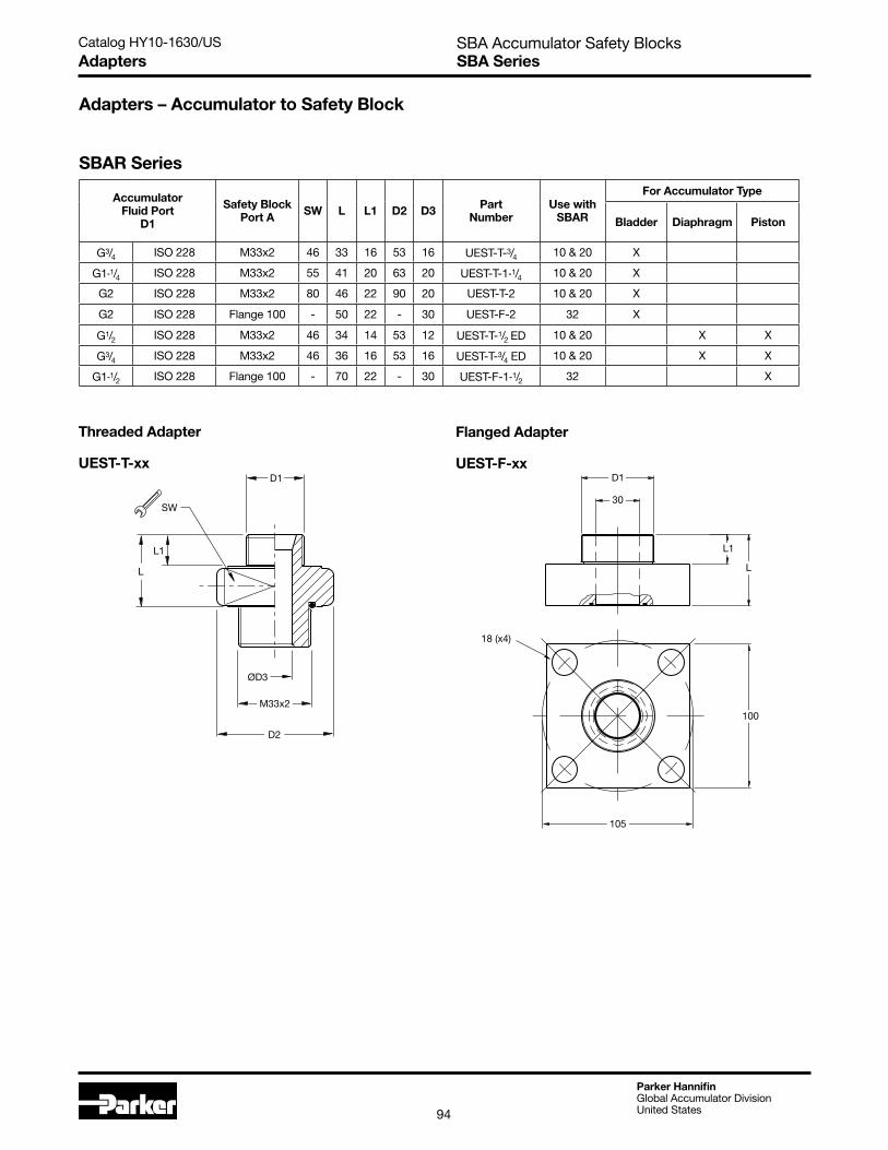
Adapters – Accumulator to Safety Block
SBAR Series
Accumulator Fluid Port
D1
Safety Block Port A SW L L1 D2 D3 Part
NumberUse with
SBAR
For Accumulator Type
Bladder Diaphragm Piston
G3/4 ISO 228 M33x2 46 33 16 53 16 UEST-T-3/4 10 & 20 X
G1-1/4 ISO 228 M33x2 55 41 20 63 20 UEST-T-1-1/4 10 & 20 X
G2 ISO 228 M33x2 80 46 22 90 20 UEST-T-2 10 & 20 X
G2 ISO 228 Flange 100 - 50 22 - 30 UEST-F-2 32 X
G1/2 ISO 228 M33x2 46 34 14 53 12 UEST-T-1/2 ED 10 & 20 X X
G3/4 ISO 228 M33x2 46 36 16 53 16 UEST-T-3/4 ED 10 & 20 X X
G1-1/2 ISO 228 Flange 100 - 70 22 - 30 UEST-F-1-1/2 32 X
Threaded Adapter
UEST-T-xx
Flanged Adapter
UEST-F-xx
SW
L1
L
D2
ØD3
D1
M33x2
D1
30
L1
L
18 (x4)
100
105
Catalog HY10-1630/US
Parker HannifinGlobal Accumulator DivisionUnited States95
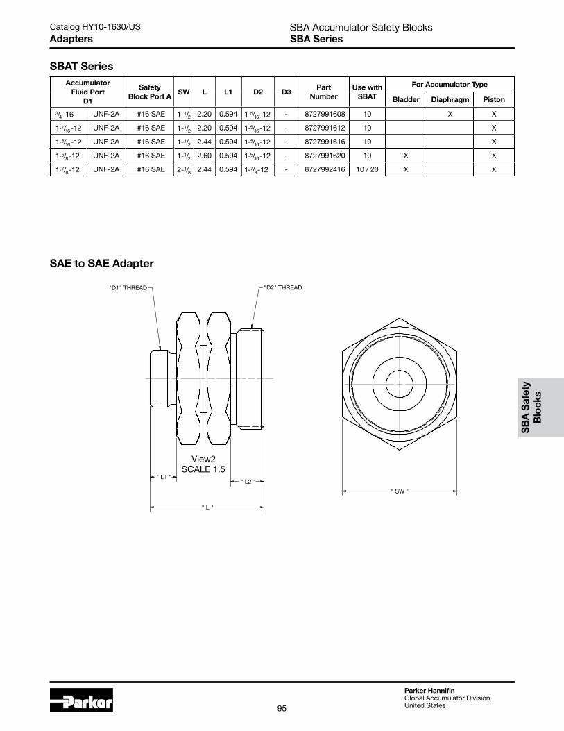
SBA Accumulator Safety BlocksSBA SeriesAdapters
SBAT SeriesAccumulator
Fluid Port D1
Safety Block Port A
SW L L1 D2 D3Part
NumberUse with
SBAT
For Accumulator Type
Bladder Diaphragm Piston
3/4 -16 UNF-2A #16 SAE 1-1/2 2.20 0.594 1-5/16 -12 - 8727991608 10 X X
1-1/16 -12 UNF-2A #16 SAE 1-1/2 2.20 0.594 1-5/16 -12 - 8727991612 10 X
1-5/16 -12 UNF-2A #16 SAE 1-1/2 2.44 0.594 1-5/16 -12 - 8727991616 10 X
1-5/8 -12 UNF-2A #16 SAE 1-1/2 2.60 0.594 1-5/16 -12 - 8727991620 10 X X
1-7/8 -12 UNF-2A #16 SAE 2-1/8 2.44 0.594 1-7/8 -12 - 8727992416 10 / 20 X X
SAE to SAE Adapter
View2SCALE 1.5
" L "
" L2 "" L1 "
"D2" THREAD"D1" THREAD
" SW "
SB
A S
afet
y B
lock
s

Catalog HY10-1630/US
Parker HannifinGlobal Accumulator DivisionUnited States96
SBA Accumulator Safety BlocksSBA SeriesOrdering Information
How to Order – Safety Block Model Code Structure
PRODUCT TYPE
SBA - SAFETY BLOCK
DISCHARGE VALVE M1------MANUAL E1------24V DC N/O E2------24V DC N/C E3------115V AC N/O E4------115V AC N/C
PRESSUREPORT
T - THREADED
SEAL COMPOUND 1---NITRILE 5---FLUOROELASTOMER
PRESSURE SETTING (CE APPROVED PRESET) (RELIEF VALVE TYPE "T") 050------SET @ 50 BAR [725 PSI] 070------SET @ 70 BAR [1015 PSI] 100------SET @ 100 BAR [1450 PSI] 120------SET @ 120 BAR [1740 PSI] 140 -----SET @ 140 BAR [2030 PSI] 160------SET @ 160 BAR [2320 PSI] 200 -----SET @ 200 BAR [2900 PSI] 210 -----SET @ 210 BAR [3045 PSI] 250 -----SET @ 250 BAR [3625 PSI] 280------SET @ 280 BAR [4061 PSI] 300 -----SET @ 300 BAR [4351 PSI] 330------SET @ 330 BAR [4786 PSI]
RELIEF VALVE TYPE T-----PRESET PRESSURE (CE APPROVED) A-----ADJUSTABLE (NON-CE)
SBA TT 1 200 A3L E1 - - DESIGN NUMBER 1----STANDARD***--SPECIAL DESIGN
1
ACCUMULATOR PORTING T---------SAE PORTS R---------BSPP PORTS
T
ADJUSTABLE (NON-CE) (RELIEF VALVE TYPE "A") 050-----26 TO 50 BAR [377 TO 725 PSI] RANGE 100-----51 TO 100 BAR [740 TO 1450 PSI] RANGE 200-----101 TO 200 BAR [1465 TO 2900 PSI] RANGE 300-----201 TO 315 BAR [2915 TO 4568 PSI] RANGE 330-----316 TO 345 BAR [4582 TO 5003 PSI] RANGE THE NON-CE PRESSURE RELIEF VALVE ONLY IS SET TO THE BOTTOM OF THE RANGE LISTED ABOVE AT THE FACTORY FOR ADJUSTMENT: CLOCKWISE WILL INCREASE PRESSURECOUNTERCLOCKWISE WILL DECREASE PRESSURE
SIZE 10------NG10 (SBAT & SBAR) 20----- NG20 (SBAT & SBAR) 32------NG32 (SBAR ONLY) 3L------NG32 W/ 2" CODE 61 (SBAT ONLY) 3P------NG32 W/ 1.5" CODE 62 (SBAT ONLY)
DESIGN MODIFICATION A--STANDARDL---LOCK-OUT TAG-OUT PLATESS--SPECIAL