sbas test-bed demonstration project · 6 sbas test-bed technical report 1 introduction a satellite...
TRANSCRIPT

0 <Insert Report Title>
SBAS TEST-BED DEMONSTRATION PROJECT
Christopher Marshall, Lachlan Ng and Eldar Rubinov FrontierSI
TECHNICAL REPORT - FRONTIERSI SBAS TESTING CAMPAIGN

1 SBAS Test-bed Technical Report
Table of Contents
1 INTRODUCTION ..................................................................................................................................... 6
2 EQUIPMENT AND OBSERVATION ENVIRONMENT ..................................................................................... 8
GNSS receiver and antenna hardware ................................................................................................. 8
Observation Environment ................................................................................................................... 9
3 TESTING CAMPAIGN DESCRIPTIONS ..................................................................................................... 10
Static testing of SBAS L1, DFMC and PPP........................................................................................... 10
Kinematic testing of SBAS L1, DFMC and PPP .................................................................................... 10
Kinematic forestry testing of SBAS L1 and PPP ................................................................................... 10
4 TESTING METHODOLOGY ..................................................................................................................... 11
Static testing with SBAS L1, DFMC and PPP ....................................................................................... 11
Static testing of consumer and mid-range equipment with SBAS L1 service .................................. 11
Static antenna testing with SBAS L1........................................................................................... 13
Static SBAS L1 vs DFMC test ..................................................................................................... 14
Static PPP test via GEO, SISNeT and RTCM ................................................................................ 14
Kinematic testing with SBAS L1, DFMC and PPP ................................................................................. 14
Forestry testing with SBAS L1 and PPP .............................................................................................. 17
5 RESULTS .............................................................................................................................................. 20
Static testing results ......................................................................................................................... 20
Static testing of consumer and mid-range equipment results ....................................................... 20
Static antenna testing with SBAS L1 results ................................................................................ 34
Static SBAS L1 vs DFMC test results ........................................................................................... 40
Static PPP test results ............................................................................................................... 42
Kinematic testing results .................................................................................................................. 46
Kinematic results of mid-range receivers with SBAS L1 ............................................................... 46
Kinematic results for DFMC ....................................................................................................... 52
Kinematic results for PPP .......................................................................................................... 60
Forestry testing results ..................................................................................................................... 63
6 DISCUSSION ........................................................................................................................................ 67
Static Analysis ................................................................................................................................. 67
Kinematic Analysis ........................................................................................................................... 67
Forestry Analysis .............................................................................................................................. 68
7 CONCLUSION ....................................................................................................................................... 69
8 REFERENCES ........................................................................................................................................ 70

2 SBAS Test-bed Technical Report
List of Figures
Figure 1. SBAS test-bed configuration (credit: Geoscience Australia). ............................................................... 6
Figure 2. Consumer receivers used for testing. ............................................................................................... 8
Figure 3. Mid-range receivers used for testing. ............................................................................................... 8
Figure 4. Septentrio AsteRx-U receiver used for testing. .................................................................................. 9
Figure 5. Antennas used for testing. ............................................................................................................... 9
Figure 6. Antenna location for the static receiver testing. .............................................................................. 11
Figure 7. Consumer-grade receiver setup for static testing. ........................................................................... 12
Figure 8. Mid-range receiver setup for static testing. ..................................................................................... 12
Figure 9. Various antenna configurations including Topcon G3-1A (A), Tallysman TW7972 with GP (B), patch
with GP (C) and patch without GP. ............................................................................................................... 13
Figure 10. Hardware setup for kinematic test 1 (left), and tests 2 and 3 (right). ............................................. 15
Figure 11. Antenna setup on the vehicle for kinematic tests 1, 2 and 3. ......................................................... 15
Figure 12. Kinematic test route. ................................................................................................................... 16
Figure 13. Images of various environments during kinematic test (A) urban canyon, (B) inner suburbs, (C)
vegetated suburbs, (D) open freeway, (E) outer suburbs (credit: Google street view). .................................... 16
Figure 14. Thinned forest track and control points. ....................................................................................... 17
Figure 15. Unthinned and native forest tracks and control points. .................................................................. 18
Figure 16. Forestry testing using magicUTs (left) and the Geode (right). ........................................................ 19
Figure 17. Consumer test 1 horizontal coordinate differences for Antenova, Quectel, SkyTraq and U-blox
receivers. ................................................................................................................................................... 22
Figure 18. Consumer test 2 horizontal plots for Quectel, SkyTraq and U-blox receivers. .................................. 23
Figure 19. Consumer test 3 horizontal plots for Quectel, SkyTraq and U-blox receivers. .................................. 24
Figure 20. Consumer test 1 vertical plots for Antenova, Quectel, SkyTraq and U-blox receivers. ...................... 25
Figure 21. Consumer test 2 vertical plots for Quectel, SkyTraq and U-blox receivers. ...................................... 26
Figure 22. Consumer test 3 vertical plots for Quectel, SkyTraq and U-blox receivers. ...................................... 27
Figure 23. Mid-range test 1 horizontal plots for Arrow Gold, Geode and magicUT receivers. ............................ 28
Figure 24. Mid-range test 2 horizontal plots for Arrow Gold, Geode and magicUT receivers. ............................ 29
Figure 25. Mid-range test 3 horizontal plots for Arrow Gold, Geode and magicUT receivers. ............................ 30
Figure 26. Mid-range test 1 vertical plots for Arrow Gold, Geode and magicUT receivers. ................................ 31
Figure 27. Mid-range test 2 vertical plots for Arrow Gold, Geode and magicUT receivers. ................................ 32
Figure 28. Mid-range test 3 vertical plots for Arrow Gold, Geode and magicUT receivers. ................................ 33
Figure 29. Horizontal plots for Topcon G3-1A antenna. .................................................................................. 35
Figure 30. Horizontal plots for Tallysman TW7972 antenna with ground plane. ............................................... 35
Figure 31. Horizontal plots for Tallysman TW7972 antenna without ground plane. .......................................... 36
Figure 32. Horizontal plots for Tallysman patch antenna with ground plane. ................................................... 36
Figure 33. Horizontal plots for patch antenna without ground plane. .............................................................. 37
Figure 34. Vertical plots for Topcon G3-1A antenna. ...................................................................................... 38
Figure 35. Vertical plots for Tallysman TW7972 with ground plane antenna. ................................................... 38
Figure 36. Vertical plots for Tallysman TW7972 without ground plane antenna. .............................................. 39
Figure 37. Vertical plots for patch antenna with ground plane. ....................................................................... 39
Figure 38. Vertical plots for patch antenna without ground plane. .................................................................. 40
Figure 39. SBAS L1 vs DFMC Plots for horizontal and vertical positioning. ....................................................... 41
Figure 40. PPP horizontal results for GEO, SISNeT and RTCM. ....................................................................... 43
Figure 41. PPP vertical Results for GEO, SiSNeT, RTCM. ................................................................................ 44
Figure 42. PPP positioning error for GEO, SiSNeT, RTCM. .............................................................................. 45

3 SBAS Test-bed Technical Report
Figure 43. Kinematic horizontal results for mid-range receivers – Drive 1. ...................................................... 47
Figure 44. Kinematic horizontal results for mid-range receivers – Drive 2. ...................................................... 48
Figure 45. Kinematic horizontal results for mid-range receivers – Drive 3. ...................................................... 49
Figure 46. Kinematic vertical results for mid-range receivers – Drive 1. .......................................................... 50
Figure 47. Kinematic vertical results for mid-range receivers – Drive 2. .......................................................... 51
Figure 48. Kinematic vertical results for mid-range receivers – Drive 3. .......................................................... 52
Figure 49. Kinematic horizontal DFMC results – Drive 1. ................................................................................ 54
Figure 50. Kinematic horizontal DFMC results – Drive 2. ................................................................................ 55
Figure 51. Kinematic horizontal DFMC results – Drive 3. ................................................................................ 56
Figure 52. Kinematic vertical DFMC results – Drive 1. .................................................................................... 57
Figure 53. Kinematic vertical DFMC results – Drive 2. .................................................................................... 58
Figure 54. Kinematic vertical DFMC results – Drive 3. .................................................................................... 59
Figure 55. Kinematic horizontal PPP results – Drives 1, 2 and 3. .................................................................... 61
Figure 56. Kinematic vertical PPP results – Drives 1, 2 and 3. ........................................................................ 62
Figure 57. Forestry testing results, thinned pine environment. ....................................................................... 64
Figure 58. Forestry testing results, unthinned pine environment. ................................................................... 65
Figure 59. Forestry testing results, native forest environment. ....................................................................... 66
List of Tables
Table 1. Equipment classifications. ................................................................................................................. 8
Table 2. Observation environment classifications. ........................................................................................... 9
Table 3. Consumer receiver static results...................................................................................................... 21
Table 4. Mid-range receiver static results. .................................................................................................... 21
Table 5. Septentrio Horizontal Results. ......................................................................................................... 34
Table 6. U-blox Horizontal Results. ............................................................................................................... 34
Table 7. Septentrio Vertical Results. ............................................................................................................. 34
Table 8. U-blox Vertical Results.................................................................................................................... 34
Table 9. Mid-range receiver static results. .................................................................................................... 40
Table 10. PPP testing results. ...................................................................................................................... 42
Table 11. SBAS L1 kinematic accuracy results. .............................................................................................. 46
Table 12. SBAS L1 kinematic availability results. ........................................................................................... 46
Table 13. DFMC kinematic accuracy results. ................................................................................................. 53
Table 14. DFMC kinematic availability results by area. ................................................................................... 53
Table 15. PPP kinematic positioning error results. ......................................................................................... 60
Table 16. PPP kinematic availability results by area. ...................................................................................... 60
Table 17. Forestry test 1 results – Thinned pine. ........................................................................................... 63
Table 18. Forestry test 2 results– Unthinned pine. ........................................................................................ 63
Table 19. Forestry test 3 results – Native forest. ........................................................................................... 63
Table 20. Forestry testing availability Statistics. ............................................................................................ 63

4 SBAS Test-bed Technical Report
List of Acronyms
Aus-NZ Australia and New Zealand
CORS Continuously Operating Reference Station
COTS Commercial off-the-shelf
DFMC Dual Frequency Multi Constellation
GDA Geocentric Datum of Australia
GEO Geostationary satellite
GNSS Global Navigation Satellite System
IMU Inertial Motion Unit
IoT Internet of Things
MGA Map Grid of Australia
NMEA National Marine Electronics Association
POI Point of interest
PPP Precise Point Positioning
RINEX Receiver INdependent Exchange
RMS Root Mean Square
RTCM Radio Technical Commission for Maritime Services
SBAS Satellite Based Augmentation System
SISNeT Signal in Space through the Internet

5 SBAS Test-bed Technical Report
List of Definitions
Term Description
Absolute
positioning
Absolute positioning refers to the method of positioning using a single GNSS
receiver. The position is determined using only the measurements made on that
receiver. It is the opposite to the relative positioning for which the receiver
position is determined relative to another receiver whose position is known.
Accuracy
Closeness of a measured position to the true position. It is commonly quantified
using the mean of measured positions over a specified period of time.
Accuracy levels have been defined as follows:
• Centimetre-level: 0-10cm
• Decimetre-level: 10-30cm
• Sub-metre level: 30cm-1m
• Metre-level: 1-10 m
Availability
The percentage of time the system is usable for positioning within a given
period. This can be affected both by issues with the provision of signals and by
the receiver environment.
Precision Refers to the spread of repeatedly measured positions around their mean. It is
commonly quantified using the standard deviation.
Test-bed A test-bed is a platform for conducting rigorous, transparent, and replicable
testing of new technologies. The use of SBAS test-beds is a well-established
method for reducing risk by evaluating technical performance and assessing costs
and benefits for an operational SBAS.

6 SBAS Test-bed Technical Report
1 Introduction
A Satellite Based Augmentation System (SBAS) is a correction service that can improve standalone Global
Navigation Satellite System (GNSS) positioning in a number of ways including accuracy, integrity and availability.
The service works by computing corrections to the satellite orbits and clocks from a set of ground based reference
stations, uploading the corrections to a geostationary satellite (GEO) via an uplink station, and disseminating the
corrections to users. This process is shown graphically in Figure 1.
Figure 1. SBAS test-bed configuration (credit: Geoscience Australia).
Since its inception as an aviation technology designed to improve landing safety, SBAS has since found use in
many non-aviation applications. Currently SBAS is implemented in several regions around the world including
North America, Europe, India and Japan.
Between January 2017 and January 2019, the Australian and New Zealand governments ran a two year (SBAS)
test-bed to test SBAS technology in the region. Throughout the course of the test-bed, three different signals were
evaluated:
• SBAS Legacy L1: the SBAS L1 signal is the single frequency service currently available in other
regions of the world. This signal provides sub-metre horizontal accuracy in real-time.
• Dual Frequency Multi-Constellation (DFMC): DFMC SBAS is the second generation SBAS
technology where two different frequencies and two (or more) constellations are used. In the case of
the Australia and New Zealand test-bed, L1/L2 GPS and E1/E5a Galileo signals were used to make
use of all available satellites. This signal also provides sub-metre horizontal accuracy in real-time.
• Precise Point Positioning (PPP): the PPP signal provides users with decimetre-level horizontal
accuracy in near real-time in clear sky conditions after an initial period of solution convergence, which
is typically 30-40 minutes.
The SBAS L1 signal was first broadcast in June 2017, followed by DFMC SBAS and PPP from October 2017 through
to January 2019. The signals were available from the Inmarsat 4F1 geostationary satellite as well as from the
internet via a standard protocols such as SISNeT (Signal in Space through the Internet) and RTCM (Radio Technical
Commission for Maritime Services). In case of RTCM, only the PPP service was available. While, SBAS is based
primarily on a space-based communications link, the added internet capability was useful to test various
parameters such as the effect of latency on the final positioning accuracy.

7 SBAS Test-bed Technical Report
FrontierSI was responsible for coordinating 27 projects across 10 different industry sectors testing SBAS
technology (FrontierSI, 2019) as well as overseeing an economic benefits study of the value that the technology
would bring to the economy of both countries (EY, 2019).
Aside from these industry projects, FrontierSI also carried out specific testing to evaluate the performance of the
currently commercially available consumer and mid-range GNSS receivers. The testing carried out by FrontierSI is
complementary to that done by the demonstrator projects. The purpose of this report is to detail the results of
FrontierSI’s testing of a selection of GNSS receivers across a range of different environments.
Three testing campaigns with a number of tests in each were carried out as part of the program. The first campaign
was aimed at testing static accuracy of a number GNSS receivers and antennas with SBAS L1, DFMC and PPP. The
second campaign investigated kinematic performance by driving a car through a range of road environments,
examining SBAS L1, DFMC and PPP performance. The third test looked at SBAS L1 accuracy in a selection of
typical forestry environments.

8 SBAS Test-bed Technical Report
2 Equipment and observation environment
Positioning performance of any satellite based navigation system depends on two key factors, which are
observation environment and the quality of GNSS receiver and antenna hardware. Both of these are explained
and categorised in this section.
GNSS receiver and antenna hardware
GNSS hardware varies significantly depending on the application. For the purpose of the testing, equipment was
broken into three categories which were; consumer-grade, mid-range and professional. Table 1 shows these three
categories including approximate price range and applications where these devices are often used.
Table 1. Equipment classifications.
Equipment Description
Consumer < $100 - consumer applications, mobile phones, IoT, trackers, etc.
Mid-range $100-$3,000 - GIS, mapping, forestry, robotics etc.
Professional > $3,000 - geodetic, surveying, high-precision applications
A number of receivers and antennas were used in the testing described in this report and these are introduced
below. Four consumer-grade receivers were used including Antenova M20050, Quectel L76-L, SkyTraq V838 and
U-blox M8N. These are shown in Figure 2.
Antenova M20050 Quectel L76-L SkyTraq V838 U-blox M8N
Figure 2. Consumer receivers used for testing.
Four mid-range receivers were used in the testing including EoS Arrow Gold, ComNav G100, Juniper Systems
Geode and GMV magicUT. The magicUT receiver is a prototype receiver developed by GMV for the Aus-NZ SBAS
test-bed, whilst the other three are commercial off-the-shelf (COTS) receivers targeted at the mid-range mapping
market. These receivers can only track the SBAS L1 signal, whereas the magicUT receiver can track and decode
all three services – SBAS L1, DFMC and PPP. The mid-range receivers are shown in Figure 3.
EOS Arrow Gold ComNav G100 Juniper Geode GMV MagicUT
Figure 3. Mid-range receivers used for testing.
9 SBAS Test-bed Technical Report
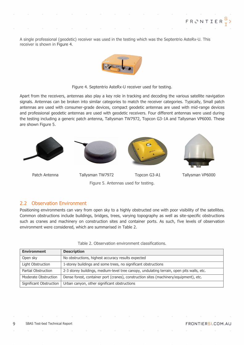
A single professional (geodetic) receiver was used in the testing which was the Septentrio AsteRx-U. This
receiver is shown in Figure 4.
Figure 4. Septentrio AsteRx-U receiver used for testing.
Apart from the receivers, antennas also play a key role in tracking and decoding the various satellite navigation
signals. Antennas can be broken into similar categories to match the receiver categories. Typically, Small patch
antennas are used with consumer-grade devices, compact geodetic antennas are used with mid-range devices
and professional geodetic antennas are used with geodetic receivers. Four different antennas were used during
the testing including a generic patch antenna, Tallysman TW7972, Topcon G3-1A and Tallysman VP6000. These
are shown Figure 5.
Patch Antenna Tallysman TW7972 Topcon G3-A1 Tallysman VP6000
Figure 5. Antennas used for testing.
Observation Environment
Positioning environments can vary from open sky to a highly obstructed one with poor visibility of the satellites.
Common obstructions include buildings, bridges, trees, varying topography as well as site-specific obstructions
such as cranes and machinery on construction sites and container ports. As such, five levels of observation
environment were considered, which are summarised in Table 2.
Table 2. Observation environment classifications.
Environment Description
Open sky No obstructions, highest accuracy results expected
Light Obstruction 1-storey buildings and some trees, no significant obstructions
Partial Obstruction 2-3 storey buildings, medium-level tree canopy, undulating terrain, open pits walls, etc.
Moderate Obstruction Dense forest, container port (cranes), construction sites (machinery/equipment), etc.
Significant Obstruction Urban canyon, other significant obstructions

10 SBAS Test-bed Technical Report
3 Testing campaign descriptions
Three separate testing campaigns were carried out which tested the various aspects on the Aus-NZ SBAS test-bed
including receiver and antenna performance of the various commercial equipment currently available as well as
the performance of different signals under different environments. These tests are described in detail below.
Static testing of SBAS L1, DFMC and PPP
A static testing campaign was carried out to examine the performance of various receivers, antennas and signals
in a static mode under open sky conditions. These tests were designed to gauge the best positioning performance
that could be obtained in a particular configuration under ideal conditions. A number of different tests were carried
out which are listed below:
• Static testing of consumer-grade and mid-range receivers with SBAS L1 service
• Static testing of various antennas with SBAS L1 service
• Static test of SBAS L1 and DFMC services using magicUT
• Static test of the PPP service via GEO, SISNeT and RTCM using magicUT
Kinematic testing of SBAS L1, DFMC and PPP
Three separate kinematic runs were carried out by driving a test vehicle around Melbourne through a series of
different environments while recording SBAS L1, DFMC and PPP signals. The logged data was used to perform the
following tests:
• Kinematic testing of SBAS L1 service using mid-range receivers
• Kinematic testing of DFMC service using mid-range and professional receivers
• Kinematic testing of PPP service using mid-range receivers
Kinematic forestry testing of SBAS L1 and PPP
The forestry testing was undertaken to test the accuracy of SBAS L1 and PPP under the dense canopy common
to forestry environments. DFMC testing was not attempted due to time constrains. Both standalone GNSS and
SBAS-augmented positioning are currently used for a range of activities associated with commercial forest
management around the world. The Aus-NZ test-bed has presented the opportunity to provide sub-metre
positional accuracy on COTS devices in harsh GNSS signal conditions where forestry personnel operate. A test-
bed project has been conducted by Forestry Corporation NSW, to determine whether receivers currently available
were suitable for use in the forestry industry. However, these tests provided inconclusive results and prompted
further testing by FrontierSI described in this report. The test methodology was developed in consultation with
forestry experts to best align with the real-world forestry practice.
The testing was carried out using MagicUT and Geode receivers in SBAS L1 and PPP modes in December 2018
across varied plantation and native forest environments at Neerim plantation, Victoria. This report describes the
methodology, results, and analysis of these tests in terms of kinematic performance.

11 SBAS Test-bed Technical Report
4 Testing methodology
This section describes the methodology of the various testing campaigns in detail, including the equipment used,
the signals tested and data processing methodology.
Static testing with SBAS L1, DFMC and PPP
Four static tests in two separate locations were completed as part of the static testing campaign. The tests were
aimed at investigating the performance of different receivers, antennas and signals in an ideal open sky
observing environment. These tests are described in detail below.
Static testing of consumer and mid-range equipment with SBAS L1 service
Prior to conducting the receiver tests, a separate static GNSS session was undertaken to establish the ground
truth of the control point for use as a reference. This involved a 24 hour observation session using the magicUT
receiver. The data was logged in a Receiver Independent Exchange (RINEX) format and was processed using the
Geoscience Australia’s AUSPOS1 online processing service. Figure 6 shows the antenna setup and testing location.
The static consumer and mid-range grade receiver tests were each conducted at a control point and compared to
the post-processed ground truth. A Topcon G3-A1 antenna on tribrach was mounted to a chimney on a single
storey residential roof in Doncaster East, Victoria. On both occasions, the receivers were connected to the antenna
via 4-way signal splitter to ensure each device experienced identical satellite conditions during the tests. Each
receiver was configured to log data simultaneously at a frequency of 1Hz using Septentrio RxTools Data Link
software.
Figure 6. Antenna location for the static receiver testing.
For the consumer receiver sessions each receiver was individually connected to a tablet via a USB hub as shown
in Figure 7. Each receiver logged data and received power via USB connection while connected to the antenna via
1 AUSPOS - http://www.ga.gov.au/bin/gps.pl

12 SBAS Test-bed Technical Report
the signal splitter. Prior to testing, the Antenova and Quectel receivers required the SBAS correction function to
be toggled on through commands in their proprietary software. Additionally, the Antenova, Quectel and SkyTraq
receivers also required commands to disable a navigation speed or position pinning threshold, which, if enabled,
would cause the receiver to repeatedly log the same position while the receiver was stationary. After configuration
and ensuring each receiver was receiving an SBAS positioning signal, the coordinates were logged in a standard
National Marine Electronics Association (NMEA) output through the Data Link software. Three independent 24
hour sessions were logged to ensure test repeatability. During the consumer test the Antenova receiver lost SBAS
fix after the first 24-hour session, so the subsequent sessions have been omitted from the analysis.
Figure 7. Consumer-grade receiver setup for static testing.
For the mid-range receiver sessions, the receivers were connected to the tablet via Bluetooth for data logging in
Data Link, with the exception of the MagicUT which logged data internally. The receivers were configured internally
through their proprietary software prior to testing. Each receiver was connected to the antenna via a passive
splitter, ensuring the same observing conditions. Like the consumer tests, three independent sessions of 24-hours
duration were logged to separate files for each receiver. The testing setup is shown in Figure 8.
Figure 8. Mid-range receiver setup for static testing.

13 SBAS Test-bed Technical Report
Static antenna testing with SBAS L1
The static antenna tests were carried out at a control point located on a residential rooftop in Maribyrnong, Victoria.
The tribrach with antenna adapter was securely mounted and levelled on a control point allowing the antennas to
be easily swapped between sessions without moving from the measured position. Two receivers, Septentrio
AsteRx-U and U-blox M8N, were connected to each antenna setup via 4-way signal splitter and logged data at
1Hz. For each antenna test the receivers were configured to log coordinate data with SBAS L1 corrections for a
period of four hours, and then the test was repeated without SBAS corrections (i.e. standalone mode). The purpose
of the tests was two-fold. Firstly, it aimed to investigate how various antennas affect the positioning quality, and
secondly to quantify the impact SBAS L1 corrections have on consumer and professional receivers.
Three different antennas were tested including a patch antenna (consumer), Tallysman TW7972 (mid-range) and
Topcon G3-1A (professional). Additionally, patch and Tallysman TW7972 were tested in two modes, with a ground
plane (GP) and without, to quantify the effect a GP can have on the positioning quality. As such, five separate
antenna configurations were tested. Four of these are shown in Figure 9.
Figure 9. Various antenna configurations including Topcon G3-1A (A), Tallysman TW7972 with GP (B), patch
with GP (C) and patch without GP.

14 SBAS Test-bed Technical Report
Static SBAS L1 vs DFMC test
A single 24-hour static SBAS L1 vs DFMC test was carried out over the same control point as the consumer and
mid-range grade receiver test, utilising the same antenna setup in Doncaster East, Victoria. Two magicUT receivers
were connected to the antenna via 4-way signal splitter. The first magicUT was configured to log positions with
SBAS L1 corrections and the second was configured to log positions using DFMC. Both receivers logged data at a
frequency of 1Hz for 24 hours. The purpose of the test was to compare how DFMC compares to SBAS L1 in terms
of accuracy and availability.
Static PPP test via GEO, SISNeT and RTCM
The static PPP test was conducted at the residential rooftop control point in Maribyrnong, Victoria. A tribrach was
securely mounted and levelled to hold a Topcon G3-A1 antenna, which was connected to three magicUTs via a 4-
way signal splitter. The first magicUT was setup to receive PPP corrections via GEO, the second to receive PPP via
SISNeT and the third to use PPP via the RTCM. The receivers positioning with PPP via SISNeT and RTCM were
connected to the local internet connection to enable the reception of PPP corrections. Once set up, the receivers
were simultaneously initialised for logging for approximately 5.5 hours. The PPP data was then compared to the
ground truth determined through post-processing the raw observations of one of the static sessions.
Corrections received via SISNeT are the same as those transmitted via the GEO, except they are received through
the internet. In that sense, the only difference is the latency with which the signals are received, which for GEO
corrections is typically 5-6 seconds, whereas for SISNeT is around 1 second. RTCM on the other hand provides a
different set of messages, based on the RTCM standard.. With the GEO broadcast, the PPP corrections are tacked
onto the SBAS corrections, hence there is some limitation to the amount of data that can be fit into the message.
With the RTCM PPP corrections there is no such limitation, and hence it is expected that PPP via RTCM would
perform better than that via GEO or SISNeT,
Apart from accuracy and availability, a key parameter for any PPP solution is the convergence time. For the
purposes of the testing, the solution was deemed to have converged when the horizontal error was less than 0.2m
and vertical error was less than 0.3m for at least 10 minutes.
Kinematic testing with SBAS L1, DFMC and PPP
The kinematic testing campaign was separated into three separate tests that ran simultaneously. The first test
focused on SBAS L1 service with mid-range receivers including the Arrow Gold, ComNav G100, Geode and
magicUT. All receivers were connected to a Tallysman VP6000 antenna through a 4-way signal splitter. The second
test focused on DFMC positioning with three different receiver configurations including:
• Septentrio AsteRx-U with DFMC via GEO
• magicUT with DFMC via GEO
• magicUT with DFMC via SISNeT
All three receivers were connected to a second Tallysman VP6000 antenna via a 4-way signal splitter. The purpose
of this test was two-fold. Firstly, to compare the performance of DFMC positioning on different receivers, and
secondly to compare the performance of DFMC positioning from two correction sources, GEO and SISNeT.
Finally, the third test looked at the performance of PPP in a kinematic environment. A single magicUT receiver
was configured in PPP mode via GEO and was connected to the second Tallysman VP6000 antenna through the
remaining port on the signal splitter. Figure 10 and Figure 11 show the receiver and antenna setup for the
kinematic tests.

15 SBAS Test-bed Technical Report
Figure 10. Hardware setup for kinematic test 1 (left), and tests 2 and 3 (right).
Figure 11. Antenna setup on the vehicle for kinematic tests 1, 2 and 3.
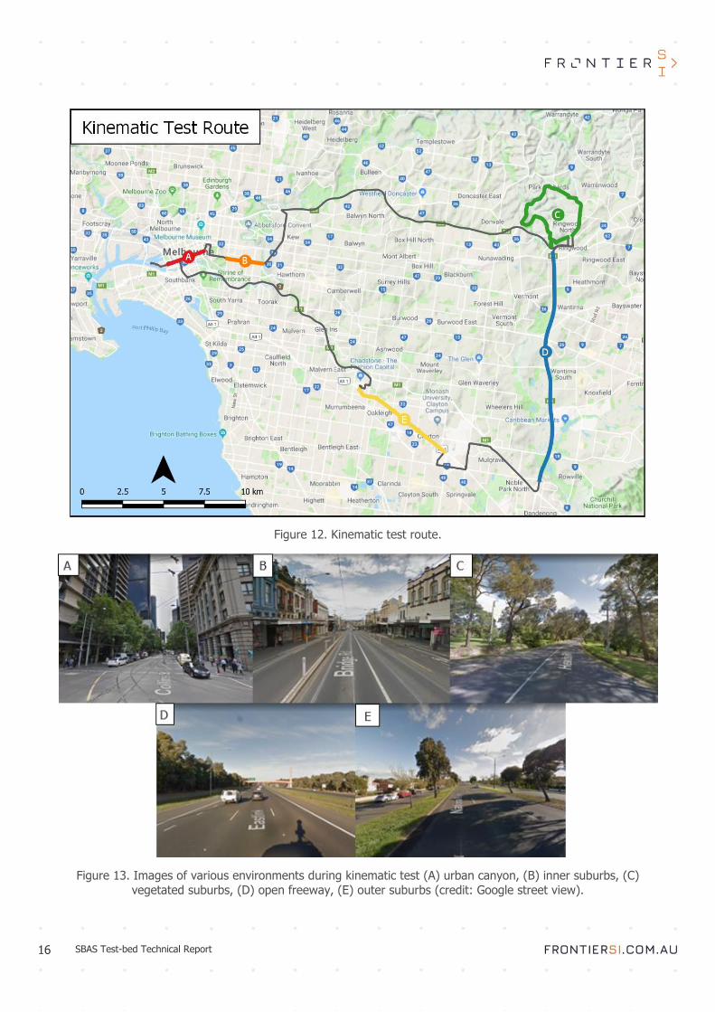
The kinematic tests used the receivers to log the position of the vehicle when driving through metropolitan
Melbourne for approximately two hours (see Figure 12). The route included a range of observing conditions
designated by letters A through to E on Figure 12 and Figure 13, which refer to the following environments,
classified as per Table 2:
A. Urban canyon (significant obstructions).
B. Inner suburbs (moderate obstructions). C. Vegetated suburbs (partial to moderate obstructions).
D. Freeway (open sky). E. Outer suburbs (open sky to moderate obstructions).
Prior to starting the drive the vehicle was stopped for approximately 30 minutes to allow the PPP receiver to converge. The route was driven on three separate occasions, providing a total of three sets of kinematic data for
each test.
16 SBAS Test-bed Technical Report
Figure 12. Kinematic test route.
Figure 13. Images of various environments during kinematic test (A) urban canyon, (B) inner suburbs, (C)
vegetated suburbs, (D) open freeway, (E) outer suburbs (credit: Google street view).

17 SBAS Test-bed Technical Report
Forestry testing with SBAS L1 and PPP
The SBAS receiver forestry tests aimed to imitate the typical scenario where foresters walk along under dense
canopy and need to have accurate and instantaneous positioning. Since it would be almost impossible to get
accurate reference position for a kinematic test under canopy, linear tracks of 100m length were established with
five pegs along each track roughly at 20m intervals. These points were measured accurately by a land survey
traverse using a total station and were used as a ground truth for subsequent SBAS measurements. Three tracks
were established in different forestry environments including unthinned pine plantation, thinned pine plantation
and native forest. Thinning operations remove every fifth row of trees, resulting in improved GNSS conditions.
Pine plantation rows oriented east-west were desirable to emulate the worst-case positioning scenario, since the
SBAS satellite (oriented approximately north) would be obstructed by the forest canopy for the majority of the
test duration. Figure 14 and Figure 15 show the unthinned, thinned and native forest tracks and the established
control points.
Figure 14. Thinned forest track and control points.

18 SBAS Test-bed Technical Report
Figure 15. Unthinned and native forest tracks and control points.
Prior to conducting the receiver tests, a total station survey was undertaken in each forest environment to establish
the ground truth position of the five forest-track control points along each linear track. The control survey involved
a two-hour static GNSS session over two control points located along a road with moderately clear overhead
conditions. Two magicUTs recorded data simultaneously with Leica AS10 antennas on tripods. These static control
points were placed so that their baseline was approximately perpendicular to the control points along the forest
track. The raw observations from the static survey were processed relative to the Ellinbank2 and Thomson Dam
reference stations from the Victorian Continuously Operating Reference Station (CORS) network GPSnet2 using
Effigis EZSurv post-processing software.
The tests were conducted using two magicUT receivers, one in SBAS L1 and one in PPP mode connected to a
single Tallysman VP6000 antenna on a survey pole logging data internally. The tests were repeated using the
Geode receiver mounted to the survey pole, logging data to an Android phone. The testing involved traversing
each forest track, stopping and levelling the pole over the control points using a bipod and recording a point of
interest (POI) for each peg. Each POI comprised of a single measurement, no averaging over a number of epochs
was done, in order to simulate the accuracy that would be achieved by walking through the forest. For the
magicUTs test, 30 minute initialisation time was needed to allow the PPP solution to converge. Figure 16 shows
the equipment used for the testing.
2 GPSnet - http://gnss.vicpos.com.au/

19 SBAS Test-bed Technical Report
Figure 16. Forestry testing using magicUTs (left) and the Geode (right).
Each track was walked three times in both directions giving a total of six measurements over each point for each
receiver. Due to time restrictions, the native forest track was only traversed using the Geode receiver.

20 SBAS Test-bed Technical Report
5 Results
Results of all the testing campaigns are presented in this section. In all cases, whether static or kinematic, the
measurements were compared to the ground truth and the differences computed. In the case of the static
experiments, the ground truth was a single point and in case of kinematic tests, the ground truth was a reference
trajectory. The results have been quantified in terms of three metrics – accuracy, precision and availability. The
accuracy is measure of closeness of a measured position to the truth and quantified by the mean of the observation
differences. Precision is a measure of the spread of the observations and is typically quantified by a standard
deviation or sigma. The outliers were removed from the dataset at a 3-sigma level, i.e. any measurement that
was more than three standard deviations away from the mean was considered an outlier and removed from the
dataset. The mean and standard deviation of the differences were calculated to quantify each receiver’s accuracy
and precision respectively.
Another useful figure that is commonly used in measurement sciences to denote the quality of the measurement
is the Root Mean Square (RMS), which is computed using:
𝑥𝑟𝑚𝑠 = √1
𝑛 (𝑥1
2 + 𝑥22 + ⋯ + 𝑥𝑛
2)
RMS is a useful quantity as it gives a combined measure of accuracy and precision in a single figure.
Finally, the availability of the dataset was computed as the number of actual measurements from the number of
available measurements rom each given dataset, after the removal of outliers.
Whilst the ComNav G100 receiver was configured to receive SBAS corrections in consultation with manufacturer;
after analysing the results it was found that the receiver was not applying those corrections correctly. As such,
the positioning performance was at the level of a standalone receiver. After discussions with the manufacturer it
was concluded, that more development work in needed in order for this receiver to be fully functional with the
Aus-NZ SBAS signal. As such, all ComNav results have been excluded from the analysis.
Static testing results
Results of the four static tests are described in this section. The signal availability for all tests was 100%, which
was expected for a static receiver in an open sky environment. As such, the availability is not reported for individual
tests in this section.
Static testing of consumer and mid-range equipment results
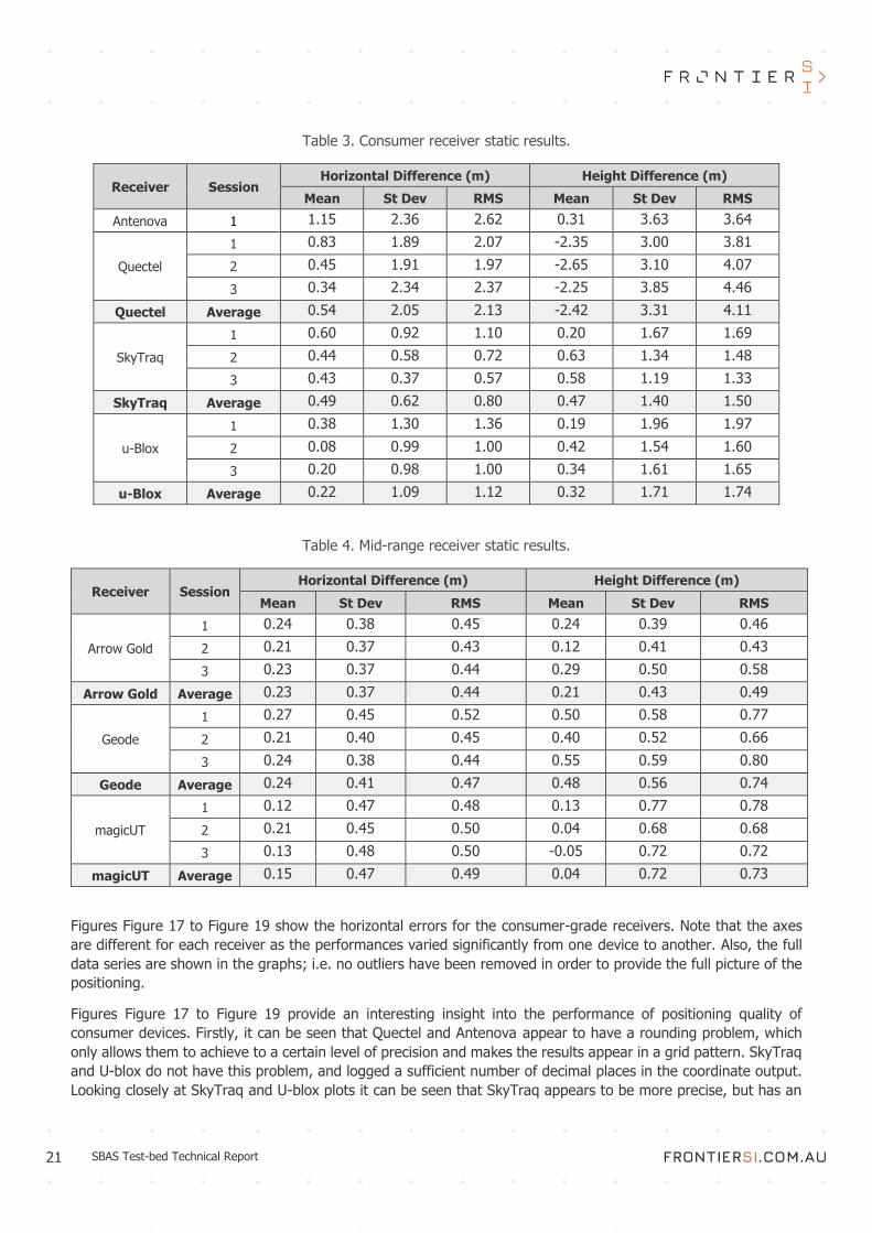
Table 3 and Table 4 give the mean, standard deviation and RMS of horizontal and vertical differences for the
consumer-grade receiver testing. The tables show the results for each of the three individual experiments as well
as the combined overall figures. Antenova results are only shown for the first experiment as the receiver failed to
output data for any future tests.
21 SBAS Test-bed Technical Report
Table 3. Consumer receiver static results.
Receiver Session Horizontal Difference (m) Height Difference (m)
Mean St Dev RMS Mean St Dev RMS
Antenova 1 1.15 2.36 2.62 0.31 3.63 3.64
Quectel
1 0.83 1.89 2.07 -2.35 3.00 3.81
2 0.45 1.91 1.97 -2.65 3.10 4.07
3 0.34 2.34 2.37 -2.25 3.85 4.46
Quectel Average 0.54 2.05 2.13 -2.42 3.31 4.11
SkyTraq
1 0.60 0.92 1.10 0.20 1.67 1.69
2 0.44 0.58 0.72 0.63 1.34 1.48
3 0.43 0.37 0.57 0.58 1.19 1.33
SkyTraq Average 0.49 0.62 0.80 0.47 1.40 1.50
u-Blox
1 0.38 1.30 1.36 0.19 1.96 1.97
2 0.08 0.99 1.00 0.42 1.54 1.60
3 0.20 0.98 1.00 0.34 1.61 1.65
u-Blox Average 0.22 1.09 1.12 0.32 1.71 1.74
Table 4. Mid-range receiver static results.
Receiver Session Horizontal Difference (m) Height Difference (m)
Mean St Dev RMS Mean St Dev RMS
Arrow Gold
1 0.24 0.38 0.45 0.24 0.39 0.46
2 0.21 0.37 0.43 0.12 0.41 0.43
3 0.23 0.37 0.44 0.29 0.50 0.58
Arrow Gold Average 0.23 0.37 0.44 0.21 0.43 0.49
Geode
1 0.27 0.45 0.52 0.50 0.58 0.77
2 0.21 0.40 0.45 0.40 0.52 0.66
3 0.24 0.38 0.44 0.55 0.59 0.80
Geode Average 0.24 0.41 0.47 0.48 0.56 0.74
magicUT
1 0.12 0.47 0.48 0.13 0.77 0.78
2 0.21 0.45 0.50 0.04 0.68 0.68
3 0.13 0.48 0.50 -0.05 0.72 0.72
magicUT Average 0.15 0.47 0.49 0.04 0.72 0.73
Figures Figure 17 to Figure 19 show the horizontal errors for the consumer-grade receivers. Note that the axes
are different for each receiver as the performances varied significantly from one device to another. Also, the full
data series are shown in the graphs; i.e. no outliers have been removed in order to provide the full picture of the
positioning.
Figures Figure 17 to Figure 19 provide an interesting insight into the performance of positioning quality of
consumer devices. Firstly, it can be seen that Quectel and Antenova appear to have a rounding problem, which
only allows them to achieve to a certain level of precision and makes the results appear in a grid pattern. SkyTraq
and U-blox do not have this problem, and logged a sufficient number of decimal places in the coordinate output.
Looking closely at SkyTraq and U-blox plots it can be seen that SkyTraq appears to be more precise, but has an

22 SBAS Test-bed Technical Report
offset of the mean (i.e. not centred around zero), whereas U-blox appears more accurate, but the spread of the
points is much wider. This is also reflected by the respective mean and standard deviation figures in Table 3.
Figure 17. Consumer test 1 horizontal coordinate differences for Antenova, Quectel, SkyTraq and U-blox
receivers.
It is also apparent that the SkyTraq appears to have recorded significantly less measurements than the U-blox.
Through examining the coordinate output , it was found that the SkyTraq appears to bin the outputs by time; i.e.
instead of providing an individual solution every second, it would provide the same solution for 30-60 seconds at
a time. This problem was discovered during the testing, however after discussion with the manufacturer, no
immediate solution seemed possible. The same problem was also present in Quectel and Antenova devices, which

23 SBAS Test-bed Technical Report
meant that only U-blox was able to provide an independent coordinate solution on a second-by-second basis. One
potential explanation is that these consumer-grade devices are targeted at kinematic applications, i.e. only
providing coordinate output when the device is moving. This assumption was not able to be verified during this
testing campaign.
Figure 18. Consumer test 2 horizontal plots for Quectel, SkyTraq and U-blox receivers.

24 SBAS Test-bed Technical Report
Figure 19. Consumer test 3 horizontal plots for Quectel, SkyTraq and U-blox receivers.
From the results in Table 3 and Figure 17 to Figure 19 it can be concluded that SkyTraq has provided the best
performance with SBAS L1 positioning with an average RMS of 0.79m, but it failed to provide an independent
coordinate output on an second-by-second basis. U-blox was the only device that able to provide an independent
output, but the spread of the results was larger with an average RMS of 1.12m.
Figure 20 to Figure 22 show the graphs for vertical positioning for the consumer devices.

25 SBAS Test-bed Technical Report
Figure 20. Consumer test 1 vertical plots for Antenova, Quectel, SkyTraq and U-blox receivers.

26 SBAS Test-bed Technical Report
Figure 21. Consumer test 2 vertical plots for Quectel, SkyTraq and U-blox receivers.

27 SBAS Test-bed Technical Report
Figure 22. Consumer test 3 vertical plots for Quectel, SkyTraq and U-blox receivers.
The vertical results reflect the picture seen in the horizontal scenario. Quectel and Antenova have the worst
performance with the vertical RMS of 4.05m and 3.64m respectively. SkyTraq has the best performance with the
RMS of 1.41m, followed by U-blox with 1.70m. U-blox time-series appear much noisier than the SkyTraq due to
the binning that is applied to the coordinates by the SkyTraq receiver.
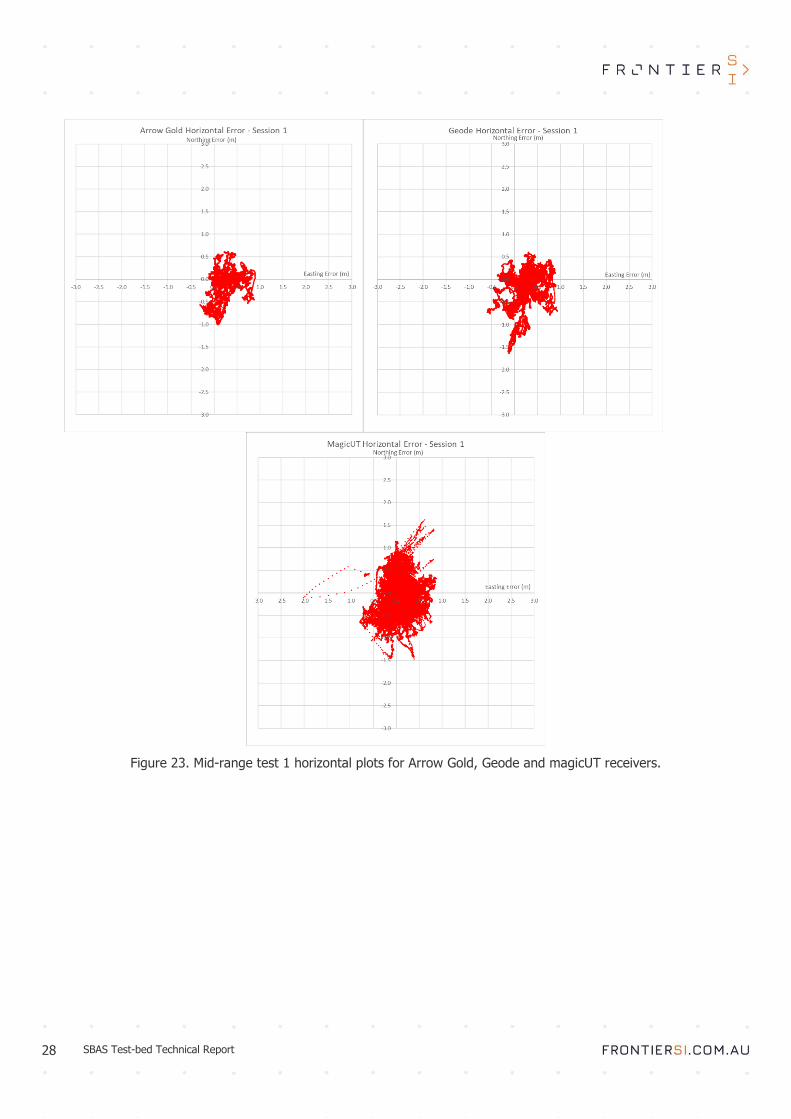
Figure 23 to Figure 25 show corresponding horizontal plots for the mid-range receivers.
28 SBAS Test-bed Technical Report
Figure 23. Mid-range test 1 horizontal plots for Arrow Gold, Geode and magicUT receivers.
29 SBAS Test-bed Technical Report
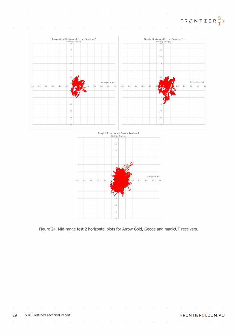
Figure 24. Mid-range test 2 horizontal plots for Arrow Gold, Geode and magicUT receivers.

30 SBAS Test-bed Technical Report
Figure 25. Mid-range test 3 horizontal plots for Arrow Gold, Geode and magicUT receivers.
It can be seen that the performance of the mid-range devices with SBAS L1 positioning is improved significantly
when compared to the consumer devices, both in terms of accuracy and precision. The Arrow Gold and the Geode
have produced almost identical results with RMS values of 0.43m and 0.44m for each device. This is potentially
due to the fact that both devices are based on the same Hemisphere GNSS board. The magicUT had very similar
performance of 0.49m RMS. This shows that mid-range devices are capable of providing horizontal positioning at
~0.5m level with SBAS L1 positioning.
Figure 26 to Figure 28 show the vertical time series for the mid-range devices.

31 SBAS Test-bed Technical Report
Figure 26. Mid-range test 1 vertical plots for Arrow Gold, Geode and magicUT receivers.

32 SBAS Test-bed Technical Report
Figure 27. Mid-range test 2 vertical plots for Arrow Gold, Geode and magicUT receivers.

33 SBAS Test-bed Technical Report
Figure 28. Mid-range test 3 vertical plots for Arrow Gold, Geode and magicUT receivers.
In the vertical domain the results were more spread than in the horizontal. Arrow Gold provided the best
performance with an RMS of 0.46m, followed by the Geode with 0.60m and magicUT with 0.69m. magicUT data
proved visibly noisier compared to both Geode and Arrow Gold. Similarly to the horizontal, Arrow Gold and the
Geode have shown very similar characteristics, having spikes at the same time in the time series.

34 SBAS Test-bed Technical Report
Static antenna testing with SBAS L1 results
The impact of the antenna on GNSS positioning quality was tested using one consumer-grade and one professional
receiver. Septentrio AsteRx-U and U-blox M8N receivers were connected to a number of different antennas from
patch to geodetic quality via a splitter. Two 4-hour datasets were recorded for each antenna, the first with both
receivers configured to receive SBAS L1 corrections, and the second with both receivers in standalone mode. Table
5 to Table 8 show the results of both receivers in horizontal and vertical modes.
Table 5. Septentrio Horizontal Results.
Antenna Setup Septentrio – SBAS L1 Septentrio – Standalone
Mean (m) St Dev (m) RMS (m) Mean (m) St Dev (m) RMS (m)
Topcon G3-A1 0.22 0.27 0.35 0.34 0.50 0.60
Tallysman TW7972 with GP 0.37 0.33 0.50 0.58 0.52 0.78
Tallysman TW7972 0.86 0.39 0.95 0.57 0.88 1.05
Patch with GP 0.37 0.45 0.58 1.16 0.32 0.97
Patch 0.99 0.47 1.09 2.47 0.58 2.53
Table 6. U-blox Horizontal Results.
Antenna Setup U-blox – SBAS L1 U-blox – Standalone
Mean (m) St Dev (m) RMS (m) Mean (m) St Dev (m) RMS (m)
Topcon G3-A1 0.21 0.72 0.75 0.90 1.43 1.69
Tallysman TW7972 with GP 0.11 0.99 1.00 0.92 1.15 1.47
Tallysman TW7972 0.79 0.84 1.15 0.66 0.85 1.07
Patch with GP 0.25 1.42 1.44 1.60 1.29 1.39
Patch 0.47 1.24 1.33 1.53 1.53 2.16
Table 7. Septentrio Vertical Results.
Antenna Setup Septentrio – SBAS L1 Septentrio – Standalone
Mean (m) St Dev (m) RMS (m) Mean (m) St Dev (m) RMS (m)
Topcon G3-A1 0.48 0.27 0.53 -0.25 0.99 1.02
Tallysman TW7972 with GP 0.99 0.26 1.02 0.35 0.35 0.49
Tallysman TW7972 0.21 0.75 0.77 -0.91 1.20 1.51
Patch with GP 1.53 0.43 1.59 -0.19 0.37 0.41
Patch 0.81 0.87 1.18 -1.11 0.49 1.22
Table 8. U-blox Vertical Results.
Antenna Setup U-blox – SBAS L1 U-blox – Standalone
Mean (m) St Dev (m) RMS (m) Mean (m) St Dev (m) RMS (m)
Topcon G3-A1 0.45 1.18 1.26 -0.11 2.11 2.12
Tallysman TW7972 with GP 1.89 1.67 2.52 -2.25 1.57 2.74
Tallysman TW7972 0.97 1.53 1.81 -2.37 1.23 2.67
Patch with GP 1.90 1.70 2.55 -1.68 2.04 2.64
Patch 1.96 2.48 3.16 -0.88 2.96 3.09
Figures Figure 29 to Figure 33 show the horizontal results for all antennas with SBAS L1 and standalone modes.

35 SBAS Test-bed Technical Report
Figure 29. Horizontal plots for Topcon G3-1A antenna.
Figure 30. Horizontal plots for Tallysman TW7972 antenna with ground plane.

36 SBAS Test-bed Technical Report
Figure 31. Horizontal plots for Tallysman TW7972 antenna without ground plane.
Figure 32. Horizontal plots for Tallysman patch antenna with ground plane.

37 SBAS Test-bed Technical Report
Figure 33. Horizontal plots for patch antenna without ground plane.
The analysis of the results shows that the quality of positioning performance increases gradually as the quality of
antenna increases. With the Septentrio receiver the RMS of the horizontal solution with SBAS L1 went from 0.35m
with the geodetic antenna to 1.09m with a patch antenna. Respective results for U-blox receiver were 0.75m to
1.33m. Another interesting finding is that with the Septentrio receiver, the impact of introducing the ground plane
to the Tallysman and patch antenna improved the results by a factor of two, whereas on the U-blox receiver the
effect was minimal.
From the Tallysman antenna experiment there was a bias evident in the Northing component, potentially caused
by the satellite geometry, which impacted the horizontal mean for both Septentrio and U-blox coordinates. The
SBAS L1 performance was generally twice as good as the standalone performance with the same antenna for both
Septentrio and U-blox receivers.
Figure 34 to Figure 38 show corresponding vertical results for the antenna testing.

38 SBAS Test-bed Technical Report
Figure 34. Vertical plots for Topcon G3-1A antenna.
Figure 35. Vertical plots for Tallysman TW7972 with ground plane antenna.

39 SBAS Test-bed Technical Report
Figure 36. Vertical plots for Tallysman TW7972 without ground plane antenna.
Figure 37. Vertical plots for patch antenna with ground plane.

40 SBAS Test-bed Technical Report
Figure 38. Vertical plots for patch antenna without ground plane.
With the vertical results, more variation was observed between the various antenna models. In general the
geodetic antenna provided the best results as expected, with the results decreasing as the antenna grade
decreased. Septentrio observed RMS values of 0.5-1.5m with both SBAS L1 and standalone, interestingly, in some
cases better standalone values were observed compared to SBAS L1 values. With U-blox, the values varied
between 1.2m to 3.1m for SBAS L1, and between 2.1m to 3.1m for standalone.
Static SBAS L1 vs DFMC test results
Table 9 and Figure 39 show the results of SBAS L1 and DFMC testing. Two magicUT receivers were connected to
the same antenna via a splitter (each configured to the respective SBAS service) and logged data for 24 hours.
The resulting coordinates were compared to the ground truth and the differences quantified.
Table 9. Mid-range receiver static results.
SBAS Service Horizontal Difference (m) Height Difference (m)
Mean St Dev RMS Mean St Dev RMS
SBAS L1 0.50 0.50 0.70 -0.66 0.51 0.83
DFMC 0.07 0.38 0.38 -0.31 0.77 0.83
41 SBAS Test-bed Technical Report
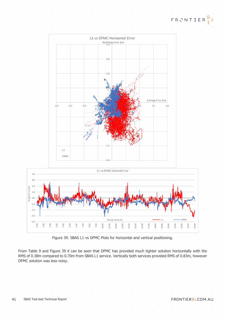
Figure 39. SBAS L1 vs DFMC Plots for horizontal and vertical positioning.
From Table 9 and Figure 39 it can be seen that DFMC has provided much tighter solution horizontally with the
RMS of 0.38m compared to 0.70m from SBAS L1 service. Vertically both services provided RMS of 0.83m, however
DFMC solution was less noisy.

42 SBAS Test-bed Technical Report
Static PPP test results
In this test the different service delivery mechanisms – GEO, SISNeT and RTCM, were examined on their effect
on the resulting positioning performance of a PPP solution. Convergence time was measured to provide an
indication of how long it would take to achieve the indicative performance. Table 10 shows the statistics for PPP
testing, and Figure 40 and Figure 41 show the plots of horizontal and vertical positioning. The horizontal position
graph shows the positions after convergence.
Table 10. PPP testing results.
PPP Service Horizontal Difference (m) Height Difference (m) Convergence
Time (min) Mean St Dev RMS Mean St Dev RMS
PPP via GEO 0.015 0.038 0.041 0.022 0.071 0.074 72
PPP via SISNeT 0.020 0.042 0.047 -0.003 0.085 0.086 83
PPP via RTCM 0.016 0.033 0.037 -0.051 0.051 0.072 29
From Table 10 it follows that all three solutions have provided very similar results at ~4cm horizontal and 7-8cm
vertical RMS figures. The biggest difference was in convergence time, where RTCM method was a clear winner
with 29 minutes compared to the 72 and 83 minutes achieved by GEO and SISNeT. This was the expected result,
as RTCM provides a more complete set of correction messages compared to the other two methods.
Figure 40 to Figure 42 show that horizontally the RTCM solution was less noisy compared to both GEO and SISNeT
solutions, which was also expected result.

43 SBAS Test-bed Technical Report
Figure 40. PPP horizontal results for GEO, SISNeT and RTCM.

44 SBAS Test-bed Technical Report
Figure 41. PPP vertical Results for GEO, SiSNeT, RTCM.

45 SBAS Test-bed Technical Report
Figure 42. PPP positioning error for GEO, SiSNeT, RTCM.

46 SBAS Test-bed Technical Report
Kinematic testing results
The results for all the kinematic tests are presented in this section.
Kinematic results of mid-range receivers with SBAS L1
The accuracy and availability of the kinematic testing campaign for Arrow Gold, Geode and magicUT receivers are
presented in Table 11 and Table 12. The results of the ComNav receiver are left out as the receiver did not function
properly in SBAS L1 mode. Kinematic availability was calculated for each road environment shown in Figure 12,
i.e. urban canyon, inner suburbs, vegetated suburbs, open freeway and outer suburbs.
Table 11. SBAS L1 kinematic accuracy results.
Receiver Drive Horizontal Difference (m) Height Difference (m)
Mean St Dev RMS Mean St Dev RMS
Arrow Gold
1 0.20 0.29 0.53 1.52 0.60 1.64
2 0.38 0.37 0.72 1.31 0.65 1.46
3 0.30 0.14 0.43 0.98 0.70 1.20
Arrow Gold Average 0.29 0.27 0.56 1.27 0.65 1.43
Geode
1 0.10 0.16 0.32 0.33 0.41 0.53
2 0.25 0.20 0.44 1.10 0.54 1.23
3 0.07 0.13 0.30 0.57 0.38 0.69
Geode Average 0.14 0.16 0.35 0.67 0.44 0.82
magicUT
1 0.21 0.42 0.73 0.74 1.10 1.34
2 0.19 0.43 0.78 0.71 1.30 1.48
3 0.28 0.34 0.67 0.71 0.76 1.04
magicUT Average 0.23 0.40 0.73 0.72 1.05 1.29
Table 12. SBAS L1 kinematic availability results.
Receiver Drive Urban Canyon Inner
Suburbs (%)
Vegetated Suburbs
(%)
Open Freeway
(%) Outer Suburbs (%)
(%)
Arrow Gold
1 68.4 100 100 98.5 100
2 87.8 100 100 98.7 100
3 53.4 100 100 98.4 100
Arrow Gold Average 69.9 100 100 98.5 100
Geode
1 55.1 100 100 98.3 100
2 65.9 100 100 98.3 100
3 28.8 100 100 98.4 100
Geode Average 49.9 100 100 98.3 100
magicUT
1 3.3 91.8 70.3 96.9 100
2 8.3 100 73.8 100 100
3 10.5 88.5 63.9 99.8 100
magicUT Average 7.4 93.4 69.3 98.9 100
From Table 12 it follows that Geode and Arrow Gold receivers achieved 98-100% availability in each of the test
environments shown in Table 12, with the exception of the urban canyon, where the average availability dropped

47 SBAS Test-bed Technical Report
to 50% and 70% respectively. The magicUT achieved over 90% availability in inner suburbs, open freeway and
outer suburbs, but in the vegetated suburbs the availability dropped to 69%. In the urban canyon, the magicUT
struggled to acquire position achieving only 7% availability.
Figure 43 to Figure 45 show the horizontal positioning errors for the mid-range receivers with the SBAS L1 service
for the three drives.
Figure 43. Kinematic horizontal results for mid-range receivers – Drive 1.

48 SBAS Test-bed Technical Report
Figure 44. Kinematic horizontal results for mid-range receivers – Drive 2.

49 SBAS Test-bed Technical Report
Figure 45. Kinematic horizontal results for mid-range receivers – Drive 3.
It is worth noting that availability figures were computed by defining a region for each observation environment
(see Figure 12) and computing how many valid epochs of data were observed as the car was driven through that
particular environment. Any position that was recorded outside of the road was considered an outlier and removed
from computation. On the other hand the horizontal positioning performance was carried out by computing a
reference trajectory (by post-processing the kinematic data from a nearby CORS) and comparing the observed
SBAS data to the trajectory. In cases where the trajectory could not be computed, the analysis could not be carried
out. A good example of that is the first 20 minutes of the drive (following convergence) as the car was in the
urban canyon environment and the reference trajectory could not be computed, but that does not necessarily

50 SBAS Test-bed Technical Report
mean that the position was not available. As such, the graphs in Figure 43 to Figure 45 do not correlate to the
availability statistics in Table 12.
From Table 11 and Figure 43 to Figure 45 it can be seen that the Geode receiver provided the best results with a
horizontal RMS of 0.35m, followed by Arrow Gold with 0.56m and magicUT with 0.73m. magicUT has proved to
be much noisier compared to the other two solutions, but an important finding was that all three receivers have
managed to maintain sub-metre horizontal positioning, which opens the door to many applications where lane-
level accuracy is required, such as road pricing. Figure 46 to Figure 48 show the corresponding vertical results for
the three receivers.
Figure 46. Kinematic vertical results for mid-range receivers – Drive 1.

51 SBAS Test-bed Technical Report
Figure 47. Kinematic vertical results for mid-range receivers – Drive 2.

52 SBAS Test-bed Technical Report
Figure 48. Kinematic vertical results for mid-range receivers – Drive 3.
The Geode receiver again achieved the best performance with a vertical RMS of 0.82m. The Arrow Gold and
magicUT receivers reported 1.43m and 1.29m vertical RMS respectively. This is a reasonable result in a challenging
environment, although generally the vertical accuracy is not as critical for transport applications. Horizontal
accuracy is of interest in most cases for automated driving and intelligent transport support; though the vertical
component is potentially necessary to aid in distinguishing between overpassing roadways and tunnels. These
obstructed environments are already challenging for GNSS positioning, suggesting integration with Inertial
Measurement Unit (IMU) to support high-accuracy tracking regardless of sky visibility.
Kinematic results for DFMC

53 SBAS Test-bed Technical Report
The accuracy and availability of the kinematic testing campaign using DFMC service is presented in Table 13 Table
14. Three receivers were used in the test – magicUT with DFMC via GEO, magicUT with DFMC via SISNeT and
Septentrio with DFMC via GEO. Kinematic availability was calculated for each road environment shown in Figure
12 as per the explanation in section 5.2.1.
Table 13. DFMC kinematic accuracy results.
Receiver Drive Horizontal Difference (m) Height Difference (m)
Mean St Dev RMS Mean St Dev RMS
magicUT DFMC via GEO
1 0.31 0.62 1.12 -0.11 1.91 1.92
2 0.12 0.66 1.31 0.02 2.84 2.84
3 0.09 0.77 1.25 0.04 2.05 2.05
magicUT DFMC via GEO Average 0.17 0.68 1.23 -0.02 2.27 2.27
magicUT DFMC via SISNeT
1 0.30 0.87 1.50 -0.21 2.78 2.79
2 0.32 0.63 1.21 0.51 3.16 3.2
3 0.29 0.76 1.28 0.26 2.65 2.66
magicUT DFMC via SISNeT Average 0.30 0.75 1.33 0.19 2.86 2.88
Septentrio DFMC via GEO
1 0.03 0.37 0.42 -0.83 1.34 1.57
2 0.34 0.46 0.84 0.18 1.77 1.78
3 0.17 0.56 0.89 -0.26 1.36 1.39
Septentrio DFMC via GEO Average 0.18 0.46 0.72 -0.30 1.49 1.58
Table 14. DFMC kinematic availability results by area.
Receiver Drive
Urban Canyon
Inner Suburbs
(%)
Vegetated Suburbs
(%)
Open Freeway
(%)
Outer Suburbs
(%) (%)
magicUT DFMC via GEO
1 6.0 94.6 56.9 98.5 100.0
2 2.6 94.6 78.6 94.1 100.0
3 0.9 95.0 59.3 96.8 100.0
magicUT DFMC via GEO Average 3.2 94.7 64.9 96.5 100.0
magicUT DFMC via SISNeT
1 13.0 89.2 45.7 97.9 100.0
2 13.6 100.0 81.3 97.8 100.0
3 0.0 94.4 56.1 96.4 100.0
magicUT DFMC via SISNeT Average 8.9 94.5 61.0 97.4 100.0
Septentrio DFMC via GEO
1 0.1 81.3 87.0 90.8 100.0
2 0.0 78.5 85.8 81.3 98.1
3 5.4 87.5 86.0 95.6 100.0
Septentrio DFMC via GEO Average 1.8 82.4 86.3 89.2 99.4
From Table 14 it can be seen that the availability statistics are worse than those for SBAS L1. This is especially
evident in the vegetated suburbs and urban canyon environment. This could be due to the fact that DFMC is still
a very new technology, for which performance is expected to improve over time as the algorithms are developed
further and bugs in the systems are eliminated. It can also be seen that the DFMC performance of the magicUT
via GEO and SISNeT were very similar, whereas the DFMC on a Septentrio receiver improved upon the accuracy
provided by both magicUT solutions. Figure 49 to Figure 51 show the horizontal performance of the three DFMC
receivers.

54 SBAS Test-bed Technical Report
Figure 49. Kinematic horizontal DFMC results – Drive 1.

55 SBAS Test-bed Technical Report
Figure 50. Kinematic horizontal DFMC results – Drive 2.

56 SBAS Test-bed Technical Report
Figure 51. Kinematic horizontal DFMC results – Drive 3.
From the figures above, it can be seen that the DFMC on a Septentrio receiver has provided superior performance
with an RMS of 0.72m, compared to the solutions from the magicUT, which appeared quite noisy and had an RMS
of 1.2-1.3m. It can also be seen that during the third drive a limited number of epochs were able to be post-
processed compared to the previous two drives. The reason for this result remains unknown. Figure 52 to Figure
54 show the corresponding vertical results.

57 SBAS Test-bed Technical Report
Figure 52. Kinematic vertical DFMC results – Drive 1.

58 SBAS Test-bed Technical Report
Figure 53. Kinematic vertical DFMC results – Drive 2.

59 SBAS Test-bed Technical Report
Figure 54. Kinematic vertical DFMC results – Drive 3.
Similar behaviour is observed in the vertical results with Septentrio DFMC solution providing the best performance.

60 SBAS Test-bed Technical Report
Kinematic results for PPP
A single magicUT receiver was used in the PPP mode during the three kinematic tests. The results of the PPP
positioning are shown in this section. Kinematic availability was calculated for each road environment shown in
Figure 12, i.e. urban canyon, inner suburbs, vegetated suburbs, open freeway and outer suburbs.
Table 15. PPP kinematic positioning error results.
Receiver Drive Horizontal Difference (m) Height Difference (m)
Mean St Dev RMS Mean St Dev RMS
magicUT PPP via GEO
1 0.25 0.19 0.45 -0.3 0.83 0.88
2 0.50 0.21 0.67 -0.45 1.16 1.25
3 0.33 0.41 0.73 -0.5 0.73 0.89
magicUT PPP via GEO Average 0.36 0.27 0.62 -0.42 0.91 1.01
Table 16. PPP kinematic availability results by area.
Receiver Drive
Urban Canyon
Inner Suburbs
(%)
Vegetated Suburbs
(%)
Open Freeway
(%)
Outer Suburbs
(%) (%)
magicUT PPP via GEO
1 13.2 98.0 58.1 94.3 99.5
2 19.5 98.6 78.0 94.8 97.3
3 1.05 97.8 58.5 93.2 99.83
magicUT PPP via GEO Average 11.3 98.1 64.9 94.1 98.9
From Table 15 and Table 16, it can be seen that the horizontal RMS was 0.62m, which is in the same range as
SBAS L1 and DFMC solutions. Whilst in static mode PPP can provide sub-decimetre level accuracy, however driving
through obstructed or partially obstructed environments is more challenging, as the solution is forced to repeatedly
re-converge, and hence the accuracy drops to the level of the SBAS solution. The availability figures were also
found to be similar to the SBAS solutions on the magicUT receivers. These results indicate that PPP may not
provide a substantial improvement over SBAS L1 or DFMC for automotive applications under challenging GNSS
environments.
Figure 55 and Figure 56 display the horizontal and vertical results for the PPP respectively.

61 SBAS Test-bed Technical Report
Figure 55. Kinematic horizontal PPP results – Drives 1, 2 and 3.

62 SBAS Test-bed Technical Report
Figure 56. Kinematic vertical PPP results – Drives 1, 2 and 3.

63 SBAS Test-bed Technical Report
Forestry testing results
The results from the forestry testing are presented in this section. The data analysis required transforming the
POI horizontal coordinates from ITRF2014 to GDA94, then converting the coordinates from geographic to Map
Grid of Australia (MGA). Subsequently, the horizontal difference in metres between the observed POI coordinates
and the truth was calculated. Since each POI represents the first epoch over a control point, the results emulate
those from a kinematic scenario, i.e. a forester walking through the environment without stopping. The mean and
standard deviation of the horizontal differences are calculated and quantify each receiver’s horizontal accuracy
and precision respectively. It should be noted that any POI further than 5m from its ground truth was deemed an
outlier and removed from the analysis. For the magicUT L1 results 13 of 60 coordinates were outliers, for the
magicUT PPP results 25 of 60 coordinates were outliers, and for the Geode L1 no coordinates were outliers.
Table 17 to Table 19 and Figure 57 to Figure 59 show the accuracy and precision statistics for each of the tested
scenarios and Table 20 shows the availability results for all three scenarios.
Table 17. Forestry test 1 results – Thinned pine.
Point magicUT L1 magicUT PPP Geode L1
Mean (m) Std Dev (m) Mean (m) Std Dev (m) Mean (m) Std Dev (m)
1 1.76 1.27 0.55 1.06 0.39 0.48
2 0.77 2.16 0.57 1.56 0.35 0.94
3 1.91 1.20 0.80 2.71 0.29 0.87
4 1.48 1.92 1.38 1.91 0.23 0.70
5 2.66 2.27 0.70 0.88 0.18 1.60
Table 18. Forestry test 2 results– Unthinned pine.
Table 19. Forestry test 3 results – Native forest. Table 20. Forestry testing availability Statistics.
Point Geode L1
Mean (m) Std Dev (m)
1 0.44 1.06
2 0.56 1.16
3 0.85 0.93
4 1.23 0.69
5 1.13 1.02
Test Receiver SBAS Availability
Thinned Pine
magicUT L1 88.5%
magicUT PPP 81.9%
Geode L1 100.0%
Unthinned Pine
magicUT L1 77.5%
magicUT PPP 60.2%
Geode L1 100.0%
Native Forest Geode L1 100.0%
Results from the testing indicate that dense forests present a difficult environment for all services tested, generally
with the results lying in the 1-2m range. The Geode with SBAS L1 has provided better performance than either of
the magicUT receivers and in some cases, was able to achieve sub-metre positioning.
Point magicUT L1 magicUT PPP Geode L1
Mean (m) Std Dev (m) Mean (m) Std Dev (m) Mean (m) Std Dev (m)
1 1.56 2.19 0.59 2.53 1.00 1.59
2 0.72 3.33 1.45 1.88 0.65 1.77
3 1.44 1.93 2.22 4.01 0.45 1.31
4 1.69 1.45 1.93 2.97 1.03 1.15
5 2.42 1.78 3.22 3.06 0.27 0.95

64 SBAS Test-bed Technical Report
Figure 57. Forestry testing results, thinned pine environment.

65 SBAS Test-bed Technical Report
Figure 58. Forestry testing results, unthinned pine environment.
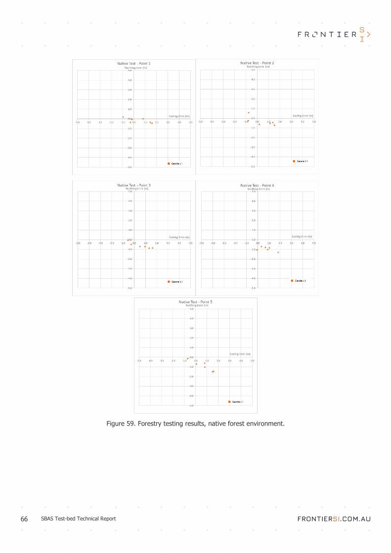
66 SBAS Test-bed Technical Report
Figure 59. Forestry testing results, native forest environment.

67 SBAS Test-bed Technical Report
6 Discussion
This section discusses the results achieved in each of the testing campaigns.
Static Analysis
Out of the consumer-grade receivers tested, the best horizontal and vertical accuracy and precision were achieved
by the SkyTraq receiver, which improved upon the standard deviation of the other receivers by 1m on average in
the horizontal component, and by 1.1m in the vertical. The Antenova, Quectel and SkyTraq receivers were still
subject to the navigational speed threshold despite disabling the setting, which meant that these receivers
recorded the same position for approximately 30-60 seconds before updating. Moreover, the Antenova and Quectel
receivers recorded NMEA coordinates to only four decimal places, which affected their precision results and caused
their scatter plot results to be in a regular grid pattern.
For the mid-range receiver static tests, the Geode and Arrow Gold provided very similar results in both horizontal
and vertical positioning. The magicUT had the lowest mean, but the standard deviations were 0.1-0.2m higher
than the other receivers. The Geode and Arrow Gold have returned very similar figures for both accuracy and
precision in the horizontal domain, though the Arrow Gold achieved smaller horizontal and vertical RMS.
The results of the static SBAS L1 vs DFMC test suggests that the magicUT positioning with DFMC provided
considerably more accurate and precise horizontal results than SBAS L1. The two receivers performed similarly in
terms of the vertical component, with the SBAS L1 slightly outperforming the DFMC receiver. Furthermore, the
SBAS L1 receiver was more reliable during testing, as the DFMC receiver lost SBAS fix multiple times during the
final 24-hours, whilst the SBAS L1 receiver maintained fix for the entire duration of testing. The performance of
DFMC is expected to continue to improve over time as the surrounding technologies mature.
The results of the PPP test provided similar results for each PPP data transfer format. PPP via RTCM had the most
precise horizontal and vertical results, confirmed through the reduced spread observed in Figure 40, Figure 41,
and Figure 42. PPP via RTCM produced a tighter clustering of positions around the ground truth and also fewer
coordinate outliers, while the scatter plots for the magicUT PPP via GEO and magicUT PPP via SISNeT were very
similar. The PPP via GEO and PPP via SISNeT results were comparable in terms of horizontal precision, while the
GEO solution performed marginally better in vertical precision. PPP via RTCM took the shortest time to converge,
taking less than half that required for PPP via GEO and PPP via SISNeT. Overall, these results indicate that the
RTCM format is the most efficient PPP data transfer format of those tested, providing more precise coordinate
solutions and a significantly shorter convergence time. However, for regions without reliable mobile network
coverage, PPP via GEO will be able to provide significant improvements over standalone GNSS.
Antenna testing showed that the receivers performed as expected in the horizontal domain. The Septentrio and
U-blox receivers both achieved the most precise results with the high-quality geodetic antenna. It is evident that
there is a trend of degrading positional quality with lower quality antennas for the horizontal results, whereby the
geodetic grade Topcon antenna often performed the best, followed by the compact Tallysman and patch antennas.
The vertical results showed similar behaviour, though with a greater degree of inconsistency. Often better
horizontal results were recorded for antennas with a ground plane, which is expected due to the reduction of
multipath error, however in some cases the ground plane did not improve vertical positioning quality significantly.
Overall, the horizontal positioning results were significantly better with SBAS compared to standalone. This
improvement was of a larger magnitude for the u-Blox receiver.
Kinematic Analysis
During the SBAS L1 kinematic tests the most accurate and precise horizontal results were from the Geode receiver.
The Arrow Gold and magicUT performed similarly, all providing a sub-metre horizontal accuracy and precision.
The Arrow Gold and the Geode receivers showed nearly 100% availability in all environments apart from the urban
68 SBAS Test-bed Technical Report
canyon, where the availability figures dropped to 70% and 50% respectively. The magicUT has showed reduced
availability compared to the other receivers.
For the DFMC kinematic tests the best results were recorded using the Septentrio DFMC via GEO, slightly out-
performing the magicUT in terms of both horizontal and vertical precision. The magicUT PPP outperformed the
DFMC receivers as expected. The magicUT receivers suffered from a large number of loss of SBAS fix notifications,
reflective of fragmentation of the satellite availability in harsher GNSS conditions.
Kinematic positioning in a moving vehicle presents the most difficult environment for any satellite-based
positioning due to the fast-changing nature of the environment and many obstructions. However, both SBAS and
PPP positioning have shown promising results at sub-metre level with good availability. The degraded performance
under challenging observation environments suggests that GNSS by itself will not be enough to position vehicles
within their lane safely and securely at all times, especially in built-up areas. The next area of research in this field
would be to integrate an Inertial Measurement Unit (IMU) to help with positioning in environments where GNSS
is lost, such as tunnels, parking garages, or urban canyons.
Forestry Analysis
Dense forest canopy also presents a difficult observing environment for many GNSS applications. Limitations in
achievable accuracy mean that foresters cannot do many tasks efficiently and introduce potential for errors. The
forestry testing carried out also produced some promising results in this area.
The most accurate and precise results under forestry conditions were achieved using the Geode Multi-GNSS; which
recorded a sub-metre accuracy at 11 of 15 forest check-points. The Geode performed best in the thinned forest
and worst in the more heavily obstructed native forest, as expected. The Geode was also the most reliable of the
receivers as it did not record any outliers, maintained an SBAS correction fix for the entire duration of all tests,
and tracked the greatest number of satellites during all tests compared to the other receivers. The magicUT PPP
results provided moderate accuracy results, recording five of 10 forest points with a sub-metre accuracy. The
magicUT PPP performed better in the thinned forest compared to the unthinned forest, as expected. The magicUT
PPP suffered significantly from loss of SBAS fix particularly during the unthinned test and it also tracked the lowest
number of satellites compared to the other solutions tested. The magicUT SBAS L1 performed most poorly out of
the tested solutions, recording only two of 10 forest points with sub-metre accuracy. The receiver performed
similarly in unthinned and thinned forest. The SBAS L1 receiver also suffered from loss of SBAS fix, observed in
the field with several loss of SBAS fix notifications occurring at the receiver during all tests.

69 SBAS Test-bed Technical Report
7 Conclusion
A series of testing campaigns including static, kinematic and forestry were carried out by FrontierSI using a variety
of receivers from consumer-grade to professional, aimed at testing SBAS L1, DFMC and PPP signals as part of the
two year Australia and New Zealand SBAS Test-bed.
A series of static tests has been conducted from March 2018 to January 2019 to quantify the static positioning
performance of a range of consumer, mid-range and professional-grade GNSS receivers and antennas. From the
results in Table 3 and Figure 17 to Figure 19 it can be concluded that SkyTraq has provided the best performance
with SBAS L1 positioning with an average RMS of 0.80m, but it failed to provide an independent coordinate output
on an second-by-second basis. U-blox was the only device that able to provide an independent output, but the
spread of the results was larger with an average RMS of 1.12m. The Arrow Gold receiver provided the best
accuracy and precision of the mid-range receivers tested; achieving a horizontal RMS of 0.44m and a vertical RMS
of 0.49m. The SBAS L1 vs DFMC tests determined that the DFMC receiver outperformed the L1 receiver in the
horizontal domain and showed a slight improvement in the vertical domain. From the PPP tests it was determined
that there are slight differences between the accuracy of the three PPP formats, with PPP via RTCM providing the
most precise results and the fastest convergence time. The antenna tests found that the horizontal positioning
quality of the antennas was significantly improved with SBAS L1 compared to standalone for each receiver, with
similar improvement in the vertical domain, though with increased inconsistency in the results. It was also shown
that the quality of antenna also plays a significant role in the resulting positioning performance.
The forestry testing was conducted in December 2018 at Neerim Plantation, Victoria, in order to assess receiver
performance under various plantation and native forest conditions. The Geode with its internal antenna offered
the highest accuracy results with sub-metre horizontal accuracies for the majority of the forest points. It was also
the most reliable receiver, as it did not lose SBAS fix throughout testing in any of the test environments. These
results suggest that the Geode using SBAS L1 positioning is capable of providing a sub-metre horizontal accuracy
in harsh GNSS conditions, thereby presenting high potential for improving the forestry industry’s operational
efficiency and safety.
Two kinematic tests were undertaken in January 2019 to quantify and compare the kinematic positioning
performance of various SBAS signals and GNSS receivers. From the SBAS L1 tests it was found that the most
accurate and precise horizontal and vertical results were from the Geode receiver, with the Arrow Gold performing
to a similar standard. The Geode and Arrow Gold receivers also performed the best in terms of availability,
recording good results even in very poor GNSS conditions. The DFMC and PPP tests determined that the most
accurate horizontal and vertical results were recorded by the magicUT PPP via GEO, followed closely by the
Septentrio DFMC. The availability analysis found variations in receiver performance across the range of test
environments, with the best result by a slight margin achieved by the magicUT PPP via GEO, followed by the
magicUT DFMC via SISNeT.
The FrontierSI testing campaign has determined that the SBAS signals provide clear benefits over standalone
GNSS in terms of accuracy, precision, and availability. These benefits vary significantly depending on the
equipment (Receiver and Antenna), and the environment in which they are operated. Each of SBAS signals
analysed in the Test-bed have shown promise for widespread use across industry. Future improvements to the
technology will likely accelerate this uptake, and deliver improved positioning, navigation, and timing for users
throughout Australia and New Zealand in the coming years.

70 SBAS Test-bed Technical Report
8 References
Digikey (2019).Antenova M20050-EVB. [image] Original available at:
https://media.digikey.com/photos/Antenova%20Photos/M20050-EVB-1.jpg [Accessed 23 Jan. 2019].
Digikey (2019).Tallysman TW7972. [image] Available at:
https://media.digikey.com/Photos/Tallysman%20Wireless/MFG_TW2x00.jpg [Accessed 23 Jan. 2019].
Quectel (2019). L76 Series EVB Kit. [image] Available at:
https://www.quectel.com/UploadImage/Product/20170413103422158.png [Accessed 23 Jan. 2019].
RF-Design (2019).EVK-M8: u-Blox M8 GNSS Evaluation Kit. [image] Available at:
https://rf-design.co.za/wp-content/uploads/2016/03/EVK-M8.jpg [Accessed 23 Jan. 2019].
Juniper Systems (2019).Geode Real-Time Sub-Metre GPS Receiver. [image] Available at:
http://www.junipersys.com/design/new_junipersys/images/2018/geode/geode.png [Accessed 23 Jan. 2019].
MGISS (2019).Arrow Gold. [image] Available at:
https://mgiss.co.uk/wp-content/uploads/2018/04/arrow-gold-front-HD.jpg [Accessed 23 Jan. 2019].
ComNav Technology (2019). G100 GNSS Receiver. [image] Available at:
http://www.comnavtech.com/UploadFile/201821224033688.jpg [Accessed 23 Jan. 2019].
TOPCON (2019).G3-A1 Antenna. [image] Available at:
http://www.topconcare.com/files/cache/20074ea5001140281c68a9b60e095f3c_f14307.jpg [Accessed 23 Jan.
2019].
Septentrio (2018). AsteRx-U. [image] Available at:
https://www.septentrio.com/sites/default/files/products/product/image_asterx-u_left_orientation_website.png
[Accessed 23 Jan. 2019].
Google. (2019). Melbourne Eastern Suburbs, VIC. Terrain basemap, Available at:
https://www.google.com/maps [Accessed 29 January 2019]
Google. (2019). Collins Street, Melbourne, VIC. Street View imagery, Available at:
https://www.google.com/maps [Accessed 7 February 2019]
Google. (2019). Bridge Road, Richmond, VIC. Street View imagery Available at:
https://www.google.com/maps [Accessed 7 February 2019]
Google. (2019). Heads Road, Donvale, VIC. Street View imagery, Available at:
https://www.google.com/maps [Accessed 7 February 2019]
Google. (2019). Eastlink, Ringwood, VIC. Street View imagery, Available at:
https://www.google.com/maps [Accessed 7 February 2019]
Google. (2019). Princes Highway, Oakleigh, VIC. Street View imagery, Available at:
https://www.google.com/maps [Accessed 7 February 2019]