sbc linear actuator catalog en - servotechnica.ru key feature of sbc linear actuator low cost-fast...
TRANSCRIPT
SBC LinearActuator
C - 1
C
C - 3
C
C - 2
I.The key feature of SBC Linear actuator
LOW COST-FAST DELIVERY
As all of our actuator products have been developed around or own SBC linear rail system wemaintain total quaility control, in-house supply lines for fast deliveries and a cost control basekeeping SBC actuators extremely price competitive
HIGH ACCURACY-HIGH REPEATABILITY
VERSATILE LOAD/SPEED CAPABILITY
HIGH RIGIDITY
DESIGN ADVANTAGES
DRIVE UNIT COMPATIBILITY
ULTIMATE CHOICE
Advantages derived through R&D gains across our liner rail and other SBC lines are immediatelytransferred into our actuators keeping them at the forefront of technology benefit. As SBC hasspecialized in Linear Rail Systems since incorporation our actuators offer the same high runningaccuracy achieved in our rail guides. Repeatability of 0.02(mm) is our standard platform.
A wide variety of rail & carraige combinations, running accuracies and sealing options means we canoffer the most versatile product combinations within the SBC actuator range. We offer products thancan handle slow moving high load applications as well as high speed high accuracy units that canhandle up to 2000mm/sec
SBC actuators utilise the strength of high grade aluminum alloy to form the external body ofeach unit supporting the inherent rigidity within our rail system.
Using a pre-designed actuator system eliminates the need for individual component matchingand the associated costs of individual item supply, assembly time, alignment time and most ofall design time. The wide range of SBC actuators means that there is inevitably a unit to suit alltypes of requirement whether system bulk or compactness is the real need.
SBC Actuators can be driven by the widest range of motor types depending on your applicationneeds. Any AC or DC, Servo or Stepper motors can be used along with whatever controlsystems are required for specific application needs
The wide range of SBC actuator models allows you to select a specific unit that best suits your needs.
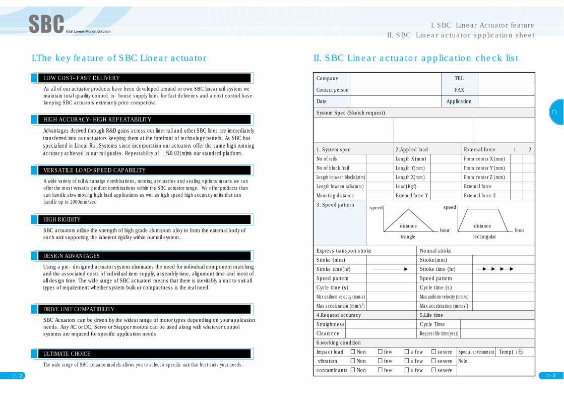
II. SBC Linear actuator application check list
triangle
distance
speed
hour hour
speed
distance
rectangular
I. SBC Linear Actuator featureII. SBC Linear actuator application sheet
Company TEL
Contact person FAX
Date Application
System Spec (Sketch request)
1. System spec 2.Applied load External force 1 2No of rails Length X (mm) From center X (mm)No of block /rail Length Y(mm) From center Y (mm)Length between blocks(mm) Length Z(mm) From center Z (mm)Length btween rails(mm) Load(Kgf) External force Mounting distance External force Y External force Z3. Speed pattern
Express transport stroke Normal strokeStroke (mm) Stroke(mm) Stroke time(hr) Stroke time (hr)Speed pattern Speed pattern Cycle time (s) Cycle time (s)Max unifrom velocity (mm/s) Max uniform velocity (mm/s)Max acceleration (mm/s2) Max acceleration (mm/s2) 4.Request accuracy 5.Life timeStraightness Cycle TimeClearance Request life time(year)6.working conditionImpact load ▫ Non ▫ few ▫ a few ▫ severe Special environment Temp( )vibration ▫ Non ▫ few ▫ a few ▫ severe contaminants ▫ Non ▫ few ▫ a few ▫ severe
Note.

C - 5
C
C - 4
1. MAX. PAY LOAD : kgf2. MAX. SPEED : mm/s3. STROKE : mm4. MAX. REPEATABILITY : mm5. Assembling : X, Y, Z axis.6. Driving force : Ball Screw / Timming Belt7. Check the external force8. Check the dimension(Select the Base )
BASIC DATA
Motor selection
III. Selection of SBC Linear Actuator
Picture 1.
1. Calculating Torque(TL)Select a motor with an appropriate drive torque rating, (TL) calculation . An undersized motorwill trip out under driving load<Calculating the Applied Torque for Ball Screw operation>
Picture 2
XY
Z
Equation of Torque
(Horizontal load) S F(safety factor) : 2~2.5
(Vertical load)
Calculating the torque for timing belt
Calculating the Torque for Ball Screw
TL Applied Torque (kgf/cm)F Axial load (kgf) = x W
( : LM coeffecient factor, W : load)
PB Ball Screw Lead (mm)
Ball Screw efficiency
0 Preload nut inside of coefficent factor
F0 Preload load.
i Deceleration rate
Ball Screw Effect ( )
Ground Ball Screw 0.9 ~ 0.95
Rplled Ball Screw 0.7 ~ 0.8
Picture2
Equation 1
Calculating the Torque for Ball Screw torque equation 2
TL = + x [kgf•cm]F•PB
21i
0FOPB
2{ }
TL= X X S•FF•PB
21i
TL= X X 2 X S•FF•PB
21i
III. Selection of SBC Linear Actuator

Important details to consider before your final selection decision
C - 7
C
C - 6
Timming Belt Torque calculaton
TL applied Torque (kgf cm)
F axial load (kg)
Timming Belt efficiency
D Pully diameter
i reduction rate
LM Guide and Timming Belt pully coefficient of friction
equation 3
Calculating the motor power (W) equation 5
Timming Belt Torque calculatonequation 4
(1) Calculation of motor power(W) After calcuating the applied torque, calculating the motor power using below equation.
W = 0.1047 x R(rpm) x Torque[N.m]
(horizontal load) S F(safety) : 2~2.5
(vertical load, but = non care, F = W)
TL = x [kgf•cm]F2
Di = FD
2 i
TL= x F xD2
1 x x S•F1i
TL= x F xD2
1 x x 2 x S•F1i
F = x W [kgf]1. Ensure that the linear actuator is suited to the working environment.
예⃞ Basic data
load : 5 kgVelocity : 500 mm/sRepeatability : 0.02 (mm)Assembling : X axis. (vertical)Stroke : 500 (mm)Driving force : Ball Screw
Motor connection : Motor direct connect.Base size(select model) : 60 ~ 90 (mm)Working conditiion: Spray machinery.
Selecting
2.Select modelCheck that linear actuator model selected can handle the parameters in the check ilst above.,if appropriate consider using SS90-D1-10-500 .3. Select motor.After selecting a linear actuator you must then consider what type of motor and controlsystem will best suit the application ensuring that the motor has appropriate torque
Using equation, calculate the Torque
Select the motor fitting for this Torque
Motor should be selected after calculating the Torque reruied to drive the loaded actuator
Check the model issuitable for the workingenvironment
Check that loads andstroke requirementsare met.
Check the basicdata(stroke, pay load, maxspeed etc)
Select the subordinateassembling model
Check the position andthe size to be suitable
for the application
Ensure that requiredaccessories such as assemblinc
bracket, cables etc
TL= x x S•FF•PB
21i
TL= x5•102 0.9
11 x 2 = 17.69[kgf•cm]
Making a selection to suit the application environment
III. Selection of SBC Linear Actuator

C - 9
C
C - 8
Important guidelines when selecting a linear actuator
1. Setting up your axes stroke range •Always keep to the minimum stroke length required to optimize the working area.•Assembling multiple axes, always keep the stroke range for Y and Z axes shorter than that
of X.•Always consider speed requirements where the long stroke moves are required.
2. Consideration of system loads•Do not exceed the catalogue load for any individual axis•Always consider additional load effects in horizontal and vertical axes.•Be aware of the effects of load under acceleration and deceleration.
3. Speed•Never exceed the allowable speed rating of the individual actuator.
4. Care on installation•Inproper installation can shorten the life of the unit regardless of the fact that it operates
within its specified load limits.
5. Environment•Always consider the working environment, heat, dust, condensation and vibration will all
have an adverse effect on any system and play an important part when selecting a suitbalemodel.
- The maximum stroke is standard length for any given actuator. The maximum error betweenthe actual moving distance and instruction value from the reference position is shown iinabsolute value.
- Halve the value of maximum difference of the measured stopping position by positioningthe carriage 7 times from a random point to the same direction along the axis. This maximumvalue can be shown with sign.
. The General Technical Data
Positioning accuracy
Repeatability accuracy
. The General Technical Data
C - 11
C
C - 10
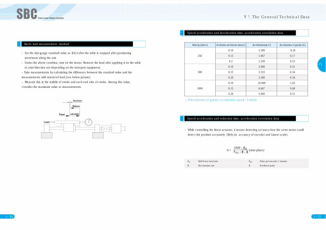
- Set the dial gauge standard value as 0 after the table is stopped after positioningmovement along the axis
- Under the above condtion, turn on the motor. Remove the load after applying it on the tableto axial direction not depending on the transport equipment.
-Take measurements by calculating the difference between the standard value and themeasurements with remval of load.(see below picture)- Measure this in the middle of stroke and each end side of stroke. Among this value,consider the maximum value as measurements.
Back-lash measurement method
Speed acceleration and deceleration time. acceleration correlation data
Speed acceleration and reduction time. acceleration correlation data
- While controlling the linear actuator, it means detecting accuracy how the servo motor coulddetect the position accurately (Rely on accuracy of encoder and Linear scale)
A = (mm/pluse)1000 PBPPG R K
Acceleration of gravity=acceleration speed / 9.8(m/s2)
PB Ball Screw Lead (m) PPG Pulse per encoder 1 rotation
R Decelaration rate K Feedback pulse
Velocity (mm/s) Acceleration and reduction time(sec) Accelertaion(m/s2) Acceleration of gravity (G)
0.10 2.500 0.26
250 0.15 1.667 0.17
0.2 1.250 0.13
0.10 5.000 0.51
500 0.15 3.333 0.34
0.20 2.500 0.34
0.10 10.000 1.02
1000 0.15 6.667 0.68
0.20 5.000 0.51
. The General Technical Data
C - 13
C
C - 12
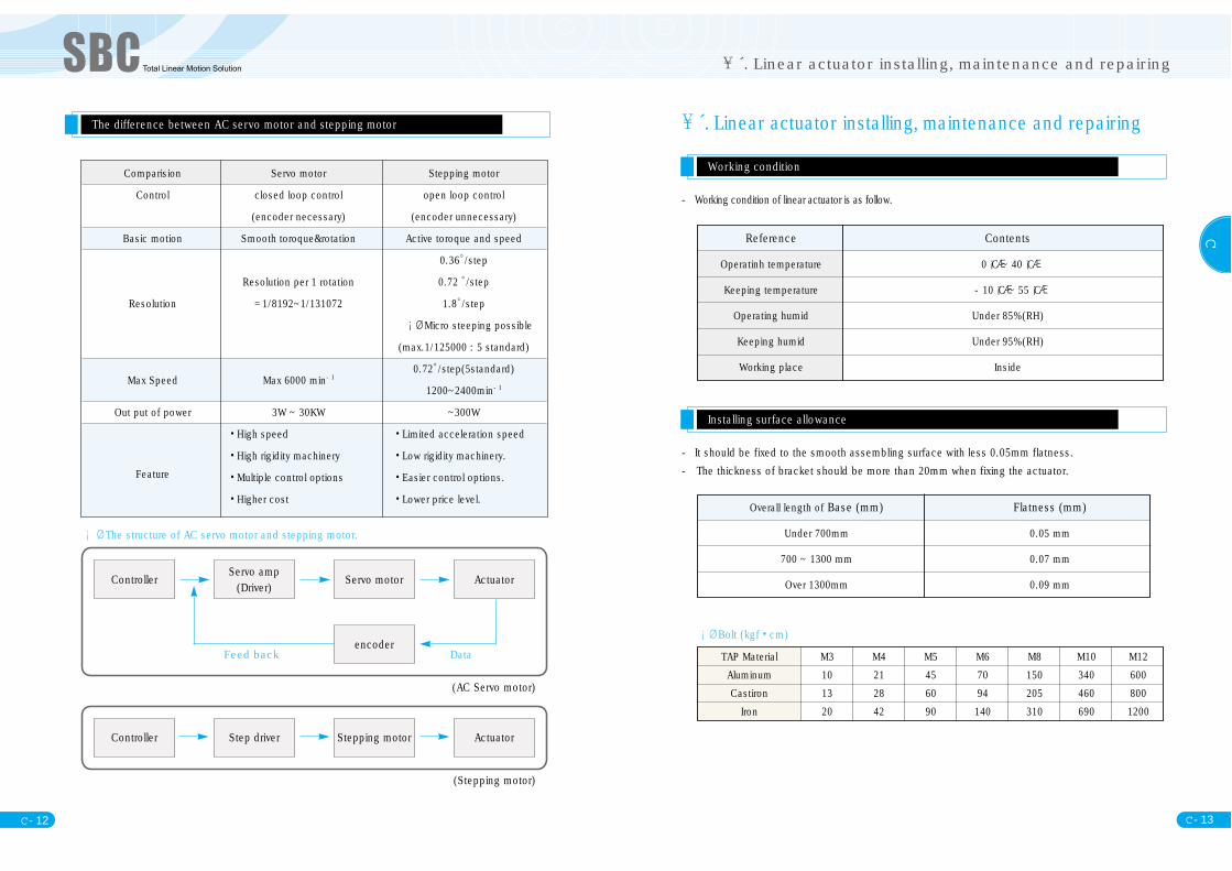
The difference between AC servo motor and stepping motor
The structure of AC servo motor and stepping motor.
(AC Servo motor)
Controller Servo amp(Driver) Servo motor
encoder
Actuator
(Stepping motor)
Controller Step driver Stepping motor Actuator
Feed back Data
Comparision Servo motor Stepping motor
Control closed loop control open loop control
(encoder necessary) (encoder unnecessary)
Basic motion Smooth toroque&rotation Active toroque and speed
0.36。/step
Resolution per 1 rotation 0.72 。/step
Resolution =1/8192~1/131072 1.8。/step
Micro steeping possible
(max.1/125000 : 5 standard)
Max Speed Max 6000 min-10.72。/step(5standard)
1200~2400min-1
Out put of power 3W ~ 30KW ~300W
•High speed •Limited acceleration speed
•High rigidity machinery •Low rigidity machinery.Feature •Multiple control options •Easier control options.
•Higher cost •Lower price level.
TAP Material M3 M4 M5 M6 M8 M10 M12Aluminum 10 21 45 70 150 340 600Castiron 13 28 60 94 205 460 800
Iron 20 42 90 140 310 690 1200
Reference Contents
Operatinh temperature 0 C ~ 40 C
Keeping temperature -10 C ~ 55 C
Operating humid Under 85%(RH)
Keeping humid Under 95%(RH)
Working place Inside
. Linear actuator installing, maintenance and repairing
Working condition
- Working condition of linear actuator is as follow.
Installing surface allowance
- It should be fixed to the smooth assembling surface with less 0.05mm flatness.- The thickness of bracket should be more than 20mm when fixing the actuator.
Bolt (kgf•cm)
Overall length of Base (mm) Flatness (mm)
Under 700mm 0.05 mm
700 ~ 1300 mm 0.07 mm
Over 1300mm 0.09 mm
. Linear actuator installing, maintenance and repairing
C - 15
C
C - 14
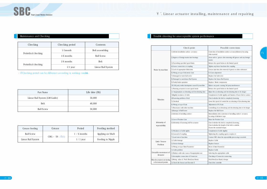
Grease feeding Grease Period Feeding method
Ball ScrewCRG - 50 (1)
1 / 6 months Applying on Shaft
Linear Rail System 1 / 1 year Feeding to Nipple
Part Name Life time (Hr)
Linear Rail System (LM Guide) 50,000
Belt 40,000
Ball Screw 50,000
Checking Checking period Contents
Periodical checking1/1month Bolt assembling
1/6 months Ball Screw
Periodical checking1/6 months Belt
1/1 year Linear Rail System
Maintenance and Checking
Checking period can be differenct according to wroking condition.Noise by machine
Vibration
Inferiority of repeatability
Limit SensorProblem
Unstable movement ofActuator
When the actuator is not movingto the instructed position
Check point Possible corrections
Trouble shooting for unacceptable system performance
1) Inferior installation surface accuracy Correction of installation surface accuracy(flatness) by using shim material
2) Ingress of foreign matter into bearings clean and re-grease after removing old grease and any foreign matter
3) Exceeding specified speed limits Reduce the speed below to the limited speed
4) Loose connectors or coupling Tighten any loose bracketor the coupling
5) Lack of appropriate lubrication Grease injection after removal of grease or alien substance
6) Wrong set up of electronic Gain P,I Gain adjustment
7) Damaged or worn ball screw Replace the ball screw
8) Damaged or wornLinear Rail System Replace the Linear Rail System
9) Faulty brake operation Replace Brake components
10) 3rd party storke interruption caused by machine Rplace any parts causing 3rd party interferencet
1) Running actuators in over speed mode Reduce the speed below to the limited speed
2) Inappropriate acceleratiing and decelerating time Adjust the accelerating and decelerating time to be longer
3)Rigidity weakness of table Complement of table rigidity and fixation of basic bolt to surface
4)Fastening problem of bolt Check whether the bolt is completely faxtening
5) Overload Lower the speed of control the accelerating of decelerating time
6) Wrong set up of Gain Adjustment of P,I Gain
7) Resonance with other machine Controllong of accelerationg and decelerating time to be longer1)Damage of Ball Screw Replace the Ball Screw
2) Inferioty of installing surface Reinstallation after correction of installing surface accuracy by using of thickness tape
3) Low of Position Gain Raise the Position Gain
4) Inferiority of fastening bolf for actuator Check whether the bolt is completely fastening. Check whether the length of the bolt is suitable.Fasten the standard torque.
5) Weakness of table rigidty Complement of table riigidity
6) Loosend of coupling Tightening the coupling again or replace it
7) Lead error of machine Contact SBC when the repeatability processing is needed.
1) Cable damage Replace Cable
2) Sensor damage Replace Sensor
3) Wrong set up of limit Parameter Reset of limit Parameter
1) Cable problem Replace Cable
2) Broken cable wire cause of inappropriate use Selecting the appropriiate cable
3) Incomplete connection of Connector Checking of Connector connecting
1)Wrong value of Pitch//Rev(Gear Ratio) Pitch/Rev(Gear Ratio) change
2) Check the Sensor and Encoder Z Check the controller
. Linear actuator installing, maintenance and repairing

MA
C - 17
C
C - 16
. Mini Linear actuator
Basic data
. Mini Linear actuator
Ball-Screw Type MA Series Belt Type MA Series
Ball-Screw Type MA Series
<Mini Linear actuator spec>
The MA series is the SBC miniaturised Linear Drive Unit of the same width and height. It ssmall and compact size package suits many application requirements. The ball screw driveunits can utilise varying leads offering stroke speed versatility. The belt drive model, usingparabolic RPP-belts, offer high-load, low-noise and precision movement. MA series can besupplied with a drive motor to suit the user s control package
40
60
75
Ground Ball Screw( 8)
RolledBall Screw( 8)
Ground Ball Screw( 12)
RolledBall Screw( 12)
Timming BeltGround
Ball Screw( 12)Rolled
Ball Screw( 12)
5 8 12 5 8 12
5 8 12
5 10 20
5 8 12
5 8 12
74.98
0.02
0.05
120
270
480
480
480
480
400
Load(kg)Lead
5
5
driving forceBody SizeBody Type
8
8
8
13
13
Repeatability(mm) Max Stroke(mm)
0.02
0.05
0.1
0.02
0.05
2. MINI Linear Actuator Structure
CouplingHigh deformation rigidity-backlash 0Clamp type-easy motormounting.Please specify diameter formotor shaft when ordering
Install PositionThe linear actuator has no positional limitationswhen working within the specified load and momentload. Vertical mounting positions must considerpossible back driving load effect on ball screws andload limits on belts. Brake motors or externallocking elements need to be considered in theseinstances..
Maintenance Both the ball screw and liner guide should bechecked periodically(400 hours operation or 3months). The stainless steel cover sheet shouldalso be checked at these times for any wear effect.
Maximum force & momentsSuyggested max load and moments loads havebeen selected based on distance from the centrepoint of the slide table. If there are loads ormoments from alternate directions, it is suggestedthat load and moment de-ratings of up to 60%should be applied against the maximumspecifications.
TemperatureMA series Mini linear actuator can be used intemperature ranging from 0~40 C. However it isrecommended to operate as close to ambient aspossible. Motors can sometimes generate hightemperatures and we recommend units to beinstalled away from external heat sources 100C
Linear GuideHigh-precision and high-loadminiature series is applied. Superaccuracy can be achieved by usingH or P grade guides(option)Achieves long, maintenance free lifeby using the ball retainer series ofminiature guide Low friction sealprovides ultimate protection and isappropriate for low motor power
Sensor(Option)Application of a photoelectricsensor-high reliability and highdurability, not affected byenvironment.Any sensor type can be fitted
Dustproof Cover*Stainless Sheet is usedPreventing dust and alien materials from gettinginside the linear actuator. Achieving longer life timeand longer maintenance intervals*Suction Ports(Option) - Using a suction port, itis more applicable for 10 class clean room
Ball ScrewVarious leadsavailable(1mm~30mm)-pleaseinquire before selecting.Preload type are available(optional).C3~C10 rrolled and ground ballscrew offers versatile lead accuracy.Low-friction and clean roomgrease can be used
C - 19
C
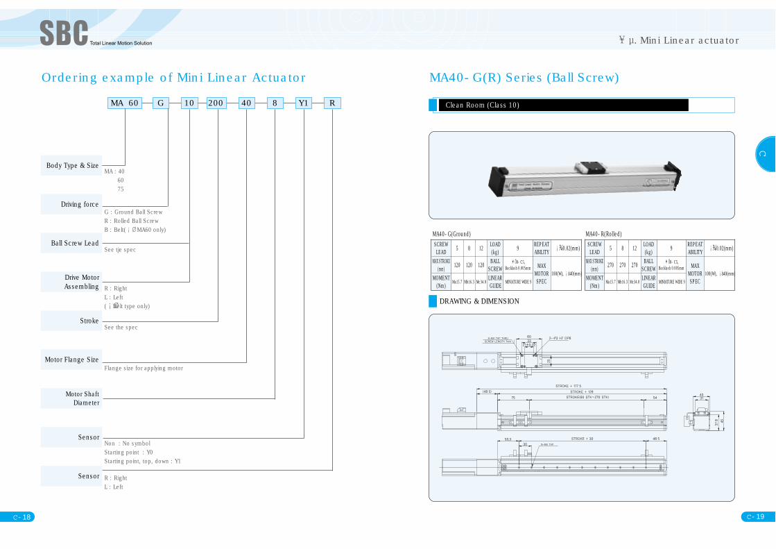
Ordering example of Mini Linear Actuator
MA 60 G 10 200 40 8 Y1 R
MA : 406075
G : Ground Ball ScrewR : Rolled Ball ScrewB : Belt( MA60 only)
See tje spec
R : Right L : Left( Belt type only)
See the spec
Flange size for applying motor
Non : No symbolStarting point : Y0Starting point, top, down : Y1
R : RightL : Left
Body Type & Size
Driving force
Ball Screw Lead
Drive MotorAssembling
Stroke
Motor Flange Size
Motor ShaftDiameter
Sensor
Sensor
C - 18
. Mini Linear actuator
MA40-G(R) Series (Ball Screw)
Clean Room (Class 10)
DRAWING & DIMENSION
MA40-G(Ground) MA40-R(Rolled)SCREW LEAD 5 8 12 LOAD
(kg) 9 REPEATABILITY 0.02(mm)
MAX STROKE(mm) 120 120 120 BALL
SCREW8-C5,
Backlash 0.005mm MAXMOTORSPEC
100(W), 40(mm)MOMENT
(Nm)Ma15.7 Mb16.3 Mc34.8
LINEARGUIDE
MINIATURE WIDE 9
SCREW LEAD 5 8 12 LOAD
(kg) 9 REPEATABILITY 0.02(mm)
MAX STROKE(mm) 270 270 270 BALL
SCREW8-C5,
Backlash 0.005mm MAXMOTORSPEC
100(W), 40(mm)MOMENT
(Nm)Ma15.7 Mb16.3 Mc34.8
LINEARGUIDE
MINIATURE WIDE 9

C - 21
C
C - 20
MA60-G(R) Series (Ball Screw)
Clean Room (Class 10)
DRAWING & DIMENSION
. Mini Linear actuator
MA40-G(Ground) MA40-R(Rolled)SCREW LEAD 5 10 20 LOAD
(kg) 9 REPEATABILITY 0.02(mm)
MAX STROKE(mm) 440 440 480 BALL
SCREW8-C5,
Backlash 0.005mm MAXMOTORSPEC
100(W), 40(mm)MOMENT
(Nm)Ma16.4 Mb18.6 Mc47.1
LINEARGUIDE
MINIATURE WIDE 9
SCREW LEAD 2 5 10 LOAD
(kg) 9 REPEATABILITY 0.05(mm)
MAX STROKE(mm) 480 480 480 BALL
SCREW12-C7,
Backlash 0.005nm MAXMOTORSPEC
100(W), 40(mm)MOMENT
(Nm)Ma16.4 Mb18.6 Mc47.1
LINEARGUIDE
MINIATURE WIDE 9
MA60-B-R Series (Belt)
High apply load, Timming Belt for high precision feed line, Clean Room (Class 10)
DRAWING & DIMENSION
MODEL BELTLEAD
MAXS TROKE(mm)
LOAD(kg) BELT LINEAR GUIDE MOMENT(Nm) REPEATABILITY MAX MOTOR SPEC
MA60-B-R 74.98 1000 8 RPP5-10 MINIATURE WIDE 12 Ma16.4 Mb18.6 Mc47.1 0.1(mm) 100(W), 40(mm)

C - 23
C
C - 22
MA60-B-L Series (Belt)
High apply load, Timming Belt for high precision feed line, Clean Room (Class 10)
DRAWING & DIMENSION
. Mini Linear actuator
MODEL BELTLEAD
MAXS TROKE(mm)
LOAD(kg) BELT LINEAR GUIDE MOMENT(Nm) REPEATABILITY MAX MOTOR SPEC
MA60-B-L 74.98 120 8 RPP5-10 MINIATURE WIDE 12 Ma16.4 Mb18.6 Mc47.1 0.1(mm) 100(W), 40(mm)
MA75-G(R) Series (Ball Screw)
Compact design, Clean Room(Class 10)
DRAWING & DIMENSION
MA75-G(Ground) MA75-R(Rolled)SCREW LEAD 2 5 10 LOAD
(kg) 9 REPEATABILITY 0.02(mm)
MAX STROKE(mm) 400 400 400 BALL
SCREW12-C7,
Backlash 0.005mm MAXMOTORSPEC
100(W), 40(mm)MOMENT
(Nm) 35.2 38.2 137LINEARGUIDE MINIATURE WIDE 15
SCREW LEAD 5 10 20 LOAD
(kg) 13 REPEATABILITY 0.02(mm)
MAX STROKE(mm) 400 400 400 BALL
SCREW12-C5,
Backlash 0.005mm MAXMOTORSPEC
100(W), 40(mm)MOMENT
(Nm) 35.2 38.2 137LINEARGUIDE MINIATURE WIDE 15
C - 25
C
C - 24
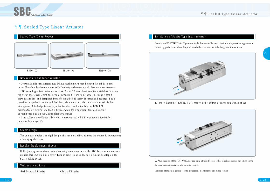
. Sealed Type Linear Actuator
Sealed Type (Clean Robot)
New revolution in linear actuator
Simple design
Resolve the slackness of cover
Various driving force
•Conventional linear actuators usually have much empty space between the unit base andcover. Therefore they become unsuitable for dusty environments and clean room requirements•SBC sealed type linear actuators such as SS and SB series have adopted a stainless cover ontop of the base cover w hich has been designed to be stick to the base. The result is that itprevents any dust and dampness from effecting the ball screw, linear rail and bearings. It cantherefore be applied in automated feed lines where dust and other contaminants exist in theatmosphere. This design is also very effective when used in the fields of LCD, PDP,semiconductor, medical and food industries where the requirement for clean workingenvironments is paramount.(clean class 10 achieved)•If the ball screw and linear rail system are raydent-treated, it is even more effective forcorrosive free longer life.
SS90-D2 SS140-P1 SB140-D3
The compact design and rigid design give more stability and suits the cosmetic requirementof many applications.
Unlikely many conventional actuators using aluminum cover, the SBC linear actuators usesan ultra thin SUS stainless cover. Even in long stroke units, no slackness develops in theSUS sealing cover.
•Ball Screw : SS series •Belt : SB series
. Sealed Type Linear Actuator
Installation of Sealed Type linear actuator
Insertion of FLAT NUT into T grooves in the bottom of linear actuator body provides appropriatemounting points and allow for positional adjustment to suit the length of the actuator
1. Please insert the FLAT NUT to T groove in the bottom of linear actuator as above
2. After insertion of the FLAT NUTS, use appropriately sized(see specifications) cap screws or bolts to fix the
linear actuator at positions suitable to the length
For more information, please see the installation, maintenance and repair section
insert
adjus
C - 27
C
C - 26
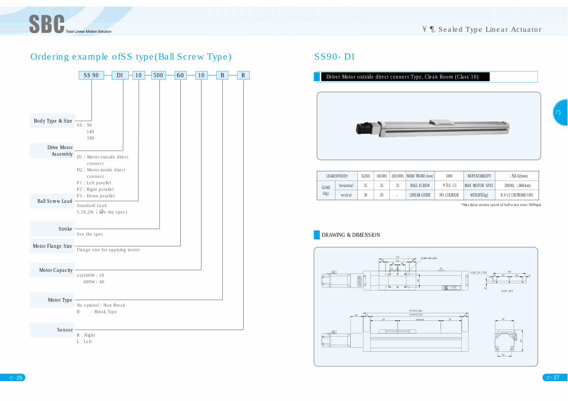
Ordering example ofSS type(Ball Screw Type)
SS 90 D1 10 500 60 10 B R
SS : 90140 180
D1 : Motor outside directconnect
D2 : Motor inside directconnect
P1 : Left parallelP2 : Right parallelP3 : Down parallel
Standard Lead5,10,20( see the spec)
See the spec
Flange size for applying motor
ex)100W : 10400W : 40
No symbol : Non BreakB : Break Type
R : RightL : Left
Body Type & Size
Drive MotorAssembly
Ball Screw Lead
Stroke
Motor Flange Size
Motor Capacity
Sensor
Motor Type
. Sealed Type Linear Actuator
SS90-D1
Driver Motor outside direct connect Type, Clean Room (Class 10)
*Max linear motion speed of ball screw verse 3000rpm
DRAWING & DIMENSION
FLAT NUT
LEAD(SPEED)* 5(250) 10(500) 20(1000) MAXS TROKE (mm) 1000 REPEATABILITY 0.02(mm)
LOAD(kg)
horizontal 35 35 25 BALL SCREW 15-C5 MAX MOTOR SPEC 200(W), 60(mm)
vertical 30 20 - LINEAR GUIDE NO.15X2BX1R WEIGHT(kg) 8.3+(1.1XSTROKE/100)
C - 29
C
C - 28
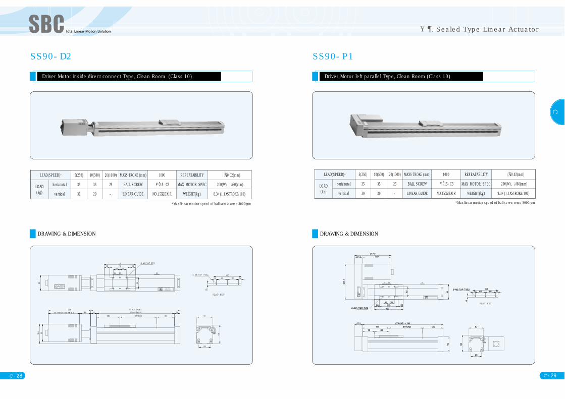
SS90-D2
Driver Motor inside direct connect Type, Clean Room (Class 10)
DRAWING & DIMENSION
*Max linear motion speed of ball screw verse 3000rpm
. Sealed Type Linear Actuator
FLAT NUT
LEAD(SPEED)* 5(250) 10(500) 20(1000) MAXS TROKE (mm) 1000 REPEATABILITY 0.02(mm)
LOAD(kg)
horizontal 35 35 25 BALL SCREW 15-C5 MAX MOTOR SPEC 200(W), 60(mm)
vertical 30 20 - LINEAR GUIDE NO.15X2BX1R WEIGHT(kg) 8.3+(1.1XSTROKE/100)
SS90-P1
Driver Motor left parallel Type, Clean Room (Class 10)
DRAWING & DIMENSION
*Max linear motion speed of ball screw verse 3000rpm
FLAT NUT
LEAD(SPEED)* 5(250) 10(500) 20(1000) MAXS TROKE (mm) 1000 REPEATABILITY 0.02(mm)
LOAD(kg)
horizontal 35 35 25 BALL SCREW 15-C5 MAX MOTOR SPEC 200(W), 60(mm)
vertical 30 20 - LINEAR GUIDE NO.15X2BX1R WEIGHT(kg) 9.3+(1.1XSTROKE/100)
C - 31
C
C - 30
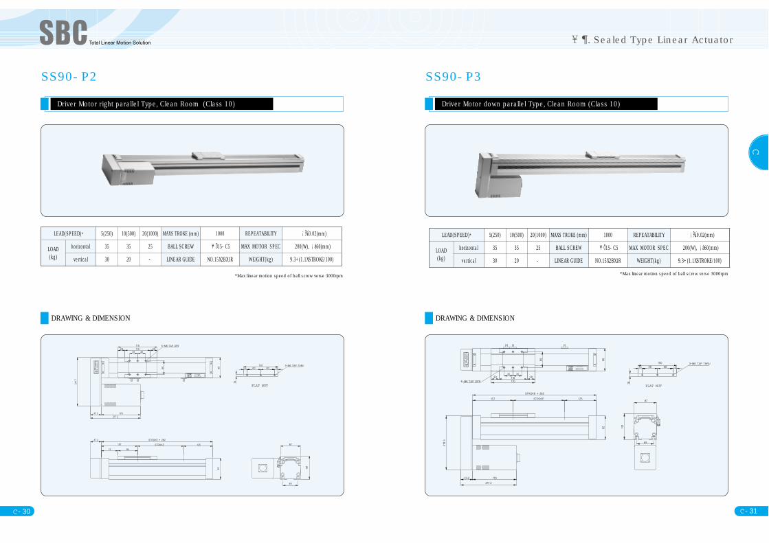
SS90-P2
Driver Motor right parallel Type, Clean Room (Class 10)
DRAWING & DIMENSION
*Max linear motion speed of ball screw verse 3000rpm
. Sealed Type Linear Actuator
FLAT NUT
LEAD(SPEED)* 5(250) 10(500) 20(1000) MAXS TROKE (mm) 1000 REPEATABILITY 0.02(mm)
LOAD(kg)
horizontal 35 35 25 BALL SCREW 15-C5 MAX MOTOR SPEC 200(W), 60(mm)
vertical 30 20 - LINEAR GUIDE NO.15X2BX1R WEIGHT(kg) 9.3+(1.1XSTROKE/100)
SS90-P3
Driver Motor down parallel Type, Clean Room (Class 10)
DRAWING & DIMENSION
*Max linear motion speed of ball screw verse 3000rpm
FLAT NUT
LEAD(SPEED)* 5(250) 10(500) 20(1000) MAXS TROKE (mm) 1000 REPEATABILITY 0.02(mm)
LOAD(kg)
horizontal 35 35 25 BALL SCREW 15-C5 MAX MOTOR SPEC 200(W), 60(mm)
vertical 30 20 - LINEAR GUIDE NO.15X2BX1R WEIGHT(kg) 9.3+(1.1XSTROKE/100)
C - 33
C
C - 32
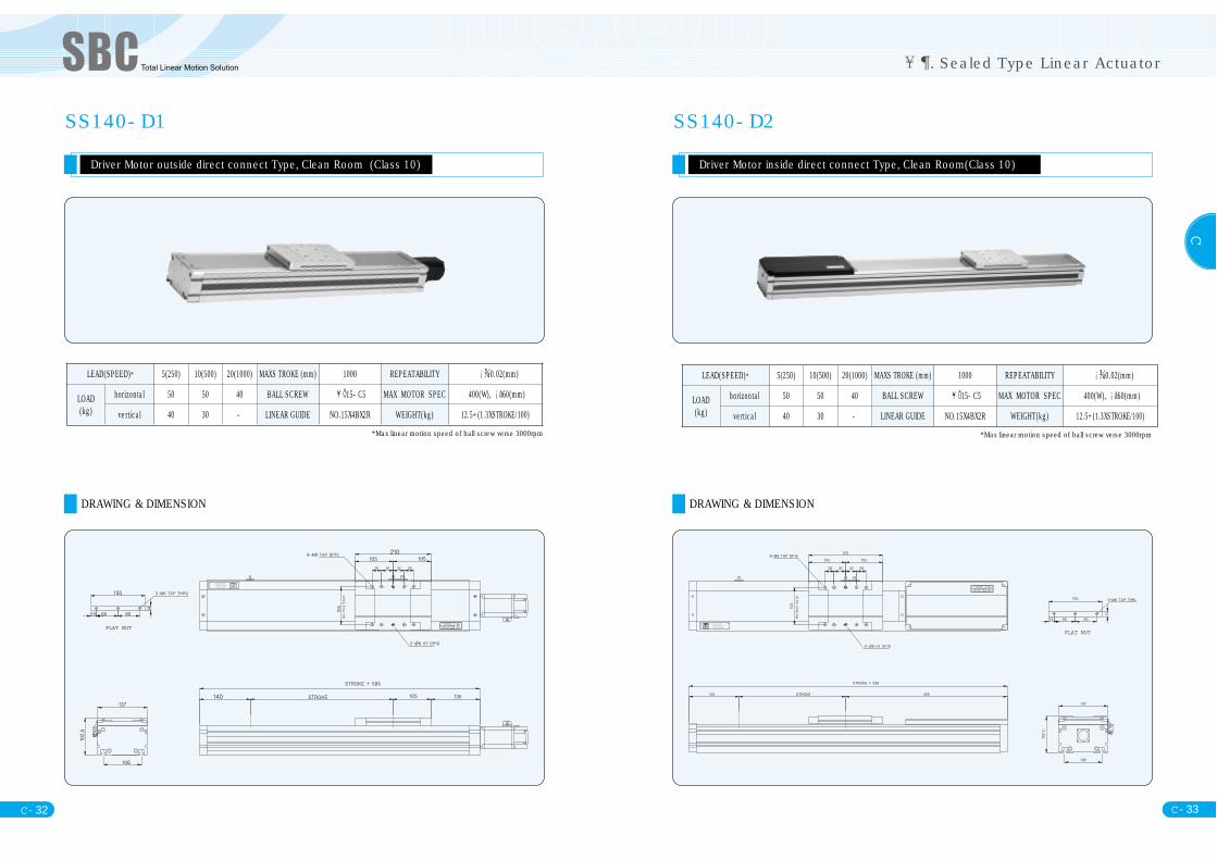
SS140-D1
Driver Motor outside direct connect Type, Clean Room (Class 10)
DRAWING & DIMENSION
*Max linear motion speed of ball screw verse 3000rpm
. Sealed Type Linear Actuator
FLAT NUT
LEAD(SPEED)* 5(250) 10(500) 20(1000) MAXS TROKE (mm) 1000 REPEATABILITY 0.02(mm)
LOAD(kg)
horizontal 50 50 40 BALL SCREW 15-C5 MAX MOTOR SPEC 400(W), 60(mm)
vertical 40 30 - LINEAR GUIDE NO.15X4BX2R WEIGHT(kg) 12.5+(1.3XSTROKE/100)
SS140-D2
Driver Motor inside direct connect Type, Clean Room(Class 10)
DRAWING & DIMENSION
*Max linear motion speed of ball screw verse 3000rpm
FLAT NUT
LEAD(SPEED)* 5(250) 10(500) 20(1000) MAXS TROKE (mm) 1000 REPEATABILITY 0.02(mm)
LOAD(kg)
horizontal 50 50 40 BALL SCREW 15-C5 MAX MOTOR SPEC 400(W), 60(mm)
vertical 40 30 - LINEAR GUIDE NO.15X4BX2R WEIGHT(kg) 12.5+(1.3XSTROKE/100)
C - 35
C
C - 34
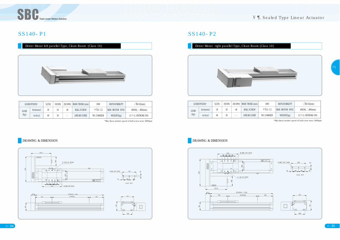
SS140-P1
Driver Motor left parallel Type, Clean Room (Class 10)
DRAWING & DIMENSION
*Max linear motion speed of ball screw verse 3000rpm
. Sealed Type Linear Actuator
FLAT NUT
LEAD(SPEED)* 5(250) 10(500) 20(1000) MAXS TROKE (mm) 1000 REPEATABILITY 0.02(mm)
LOAD(kg)
horizontal 50 50 40 BALL SCREW 15-C5 MAX MOTOR SPEC 400(W), 60(mm)
vertical 40 30 - LINEAR GUIDE NO.15X4BX2R WEIGHT(kg) 13.7+(1.3XSTROKE/100)
SS140-P2
Driver Motor right parallel Type, Clean Room (Class 10)
DRAWING & DIMENSION
*Max linear motion speed of ball screw verse 3000rpm
FLAT NUT
LEAD(SPEED)* 5(250) 10(500) 20(1000) MAXS TROKE (mm) 1000 REPEATABILITY 0.02(mm)
LOAD(kg)
horizontal 50 50 40 BALL SCREW 15-C5 MAX MOTOR SPEC 400(W), 60(mm)
vertical 40 30 - LINEAR GUIDE NO.15X4BX2R WEIGHT(kg) 13.7+(1.3XSTROKE/100)

C - 37
C
C - 36
SS140-P3
Driver Motor down parallel Type, Clean Room (Class 10)
DRAWING & DIMENSION
*Max linear motion speed of ball screw verse 3000rpm
. Sealed Type Linear Actuator
FLAT NUT
LEAD(SPEED)* 5(250) 10(500) 20(1000) MAXS TROKE (mm) 1000 REPEATABILITY 0.02(mm)
LOAD(kg)
horizontal 50 50 40 BALL SCREW 15-C5 MAX MOTOR SPEC 400(W), 60(mm)
vertical 40 30 - LINEAR GUIDE NO.15X4BX2R WEIGHT(kg) 13.7+(1.3XSTROKE/100)
SS180-D1
Driver Motor outside direct connect Type, Clean Room (Class 10)
DRAWING & DIMENSION
*Max linear motion speed of ball screw verse 3000rpm
FLAT NUT
LEAD(SPEED)* 5(250) 10(500) 20(1000) MAXS TROKE (mm) 1000 REPEATABILITY 0.02(mm)
LOAD(kg)
horizontal 90 85 65 BALL SCREW 15-C5 MAX MOTOR SPEC 750(W), 60(mm)
vertical 48 40 - LINEAR GUIDE NO.20X4BX2R WEIGHT(kg) 21.8+(2.1XSTROKE/100)

C - 39
C
C - 38
. Sealed Type Linear Actuator
SS180-D2
Driver Motor inside direct connect Type, Clean Room (Class 10)
DRAWING & DIMENSION
*Max linear motion speed of ball screw verse 3000rpm
FLAT NUT
LEAD(SPEED)* 5(250) 10(500) 20(1000) MAXS TROKE (mm) 1000 REPEATABILITY 0.02(mm)
LOAD(kg)
horizontal 90 85 65 BALL SCREW 20-C5 MAX MOTOR SPEC 750(W), 60(mm)
vertical 48 40 - LINEAR GUIDE NO.20X4BX2R WEIGHT(kg) 21.8+(2.1XSTROKE/100)
SS180-P1
Driver Motor Left Pareller Type,: Clean Room (Class 10)
DRAWING & DIMENSION
*Max linear motion speed of ball screw verse 3000rpm
FLAT NUT
LEAD(SPEED)* 5(250) 10(500) 20(1000) MAXS TROKE (mm) 1000 REPEATABILITY 0.02(mm)
LOAD(kg)
horizontal 90 85 65 BALL SCREW 20-C5 MAX MOTOR SPEC 750(W), 60(mm)
vertical 48 40 - LINEAR GUIDE NO.20X4BX2R WEIGHT(kg) 21.8+(2.1XSTROKE/100)
C
. Sealed Type Linear Actuator
C- 40 C- 41
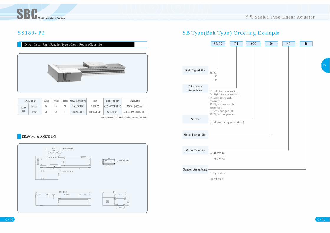
SS180-P2
Driver Motor Right Parallel Type : Clean Room (Class 10)
DRAWING & DIMENSION
*Max linear motion speed of ball screw verse 3000rpm
FLAT NUT
LEAD(SPEED)* 5(250) 10(500) 20(1000) MAXS TROKE (mm) 1000 REPEATABILITY 0.02(mm)
LOAD(kg)
horizontal 90 85 65 BALL SCREW 20-C5 MAX MOTOR SPEC 750(W), 60(mm)
vertical 48 40 - LINEAR GUIDE NO.20X4BX2R WEIGHT(kg) 22.8+(2.1XSTROKE/100)
SB Type(Belt Type) Ordering Example
SB 90 P4 1000 60 40 R
SB:90140180
D3:Left direct connectionD4:Right direct connectionP4:Left upper parallelconnectionP5:Right upper parallelconnectionP6:Left down parallelP7:Right down parallel
( See the specification)
ex)400W:40
750W:75
R:Right side
L:Left side
Body Type&Size
Drive MotorAssembling
Stroke
Motor Flange Size
Motor Capacity
Sensor Assembling
C
. Sealed Type Linear Actuator
C- 42 C- 43
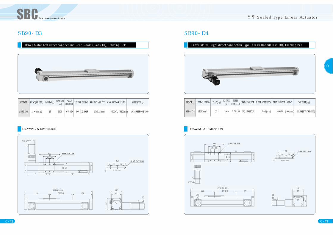
SB90-D3
Driver Motor Left direct connection: Clean Room (Class 10), Timming Belt
DRAWING & DIMENSION
FLAT NUT
MODEL LEAD(SPEED) LOAD(kg) MAX STROKE(mm)
PULLYDIAMETER LINEAR GUIDE REPEATABILITY MAX MOTOR SPEC WEIGHT(kg)
SB90-D3 1500(mm/s) 25 3000 44.56 NO.15X2BX1R 0.1(mm) 400(W), 60(mm) 10.3+(1.1XSTROKE/100)
DRAWING & DIMENSION
SB90-D4
Driver Motor Right direct connection Type : Clean Room(Class 10), Timming Belt
FLAT NUT
MODEL LEAD(SPEED) LOAD(kg) MAX STROKE(mm)
PULLYDIAMETER LINEAR GUIDE REPEATABILITY MAX MOTOR SPEC WEIGHT(kg)
SB90-D4 1500(mm/s) 25 3000 44.56 NO.15X2BX1R 0.1(mm) 400(W), 60(mm) 10.3+(1.1XSTROKE/100)

C
. Sealed Type Linear Actuator
C- 44 C- 45
SB90-P4
Driver Motor Left upper parallel Type: Clean Room (Class 10), Timming Belt
DRAWING & DIMENSION
FLAT NUT
MODEL LEAD(SPEED) LOAD(kg) MAX STROKE(mm)
PULLYDIAMETER LINEAR GUIDE REPEATABILITY MAX MOTOR SPEC WEIGHT(kg)
SB90-P4 1500(mm/s) 25 3000 44.56 NO.15X2BX1R 0.1(mm) 400(W), 60(mm) 10.3+(1.1XSTROKE/100)
SB90-P5
Driver Motor Right upper parallel Type: Clean Room (Class 10), Timming Belt
DRAWING & DIMENSION
FLAT NUT
MODEL LEAD(SPEED) LOAD(kg) MAX STROKE(mm)
PULLYDIAMETER LINEAR GUIDE REPEATABILITY MAX MOTOR SPEC WEIGHT(kg)
SB90-P3 1500(mm/s) 25 3000 44.56 NO.15X2BX1R 0.1(mm) 400(W), 60(mm) 10.3+(1.1XSTROKE/100)

C
. Sealed Type Linear Actuator
C- 46 C- 47
SB90-P6
Driver Motor Left down parallel Type: Clean Room (Class 10), Timming Belt
DRAWING & DIMENSION
FLAT NUT
MODEL LEAD(SPEED) LOAD(kg) MAX STROKE(mm)
PULLYDIAMETER LINEAR GUIDE REPEATABILITY MAX MOTOR SPEC WEIGHT(kg)
SB90-P6 1500(mm/s) 25 3000 44.56 NO.15X2BX1R 0.1(mm) 400(W), 60(mm) 10.3+(1.1XSTROKE/100)
SB90-P7
Driver Motor Right down parallel Type: Clean Room (Class 10), Timming Belt
DRAWING & DIMENSION
FLAT NUT
MODEL LEAD(SPEED) LOAD(kg) MAX STROKE(mm)
PULLYDIAMETER LINEAR GUIDE REPEATABILITY MAX MOTOR SPEC WEIGHT(kg)
SB90-P7 1500(mm/s) 25 3000 44.56 NO.15X2BX1R 0.1(mm) 400(W), 60(mm) 10.3+(1.1XSTROKE/100)

C
. Sealed Type Linear Actuator
C- 48 C- 49
SB140-D3
Driver Motor Left direct connection Type: Clean Room(Class 10), Timming Belt
DRAWING & DIMENSION
FLAT NUT
MODEL LEAD(SPEED) LOAD(kg) MAX STROKE(mm)
PULLYDIAMETER LINEAR GUIDE REPEATABILITY MAX MOTOR SPEC WEIGHT(kg)
SB140-D3 2000(mm/s) 25 1000 44.56 NO.15X4BX2R 0.1(mm) 400(W), 60(mm) 12.5+(1.3XSTROKE/100)
SB140-D4
Driver Motor Right direct connection Type: Clean Room(Class 10), Timming Belt
DRAWING & DIMENSION
FLAT NUT
MODEL LEAD(SPEED) LOAD(kg) MAX STROKE(mm)
PULLYDIAMETER LINEAR GUIDE REPEATABILITY MAX MOTOR SPEC WEIGHT(kg)
SB140-D4 2000(mm/s) 25 1000 44.56 NO.15X4BX2R 0.1(mm) 400(W), 60(mm) 12.5+(1.3XSTROKE/100)

C
. Sealed Type Linear Actuator
C- 50 C- 51
SB140-P4
Driver Motor Left upper parallel Type: Clean Room (Class 10), Timming Belt
DRAWING & DIMENSION
FLAT NUT
MODEL LEAD(SPEED) LOAD(kg) MAX STROKE(mm)
PULLYDIAMETER LINEAR GUIDE REPEATABILITY MAX MOTOR SPEC WEIGHT(kg)
SB140-P4 2000(mm/s) 25 1000 44.56 NO.15X4BX2R 0.1(mm) 400(W), 60(mm) 12.5+(1.3XSTROKE/100)
SB140-P5
Driver Motor Right upper parallel Type: Clean Room (Class 10), Timming Belt
DRAWING & DIMENSION
FLAT NUT
MODEL LEAD(SPEED) LOAD(kg) MAX STROKE(mm)
PULLYDIAMETER LINEAR GUIDE REPEATABILITY MAX MOTOR SPEC WEIGHT(kg)
SB140-P5 2000(mm/s) 25 1000 44.56 NO.15X4BX2R 0.1(mm) 400(W), 60(mm) 12.5+(1.3XSTROKE/100)
C
. Sealed Type Linear Actuator
C- 52 C- 53
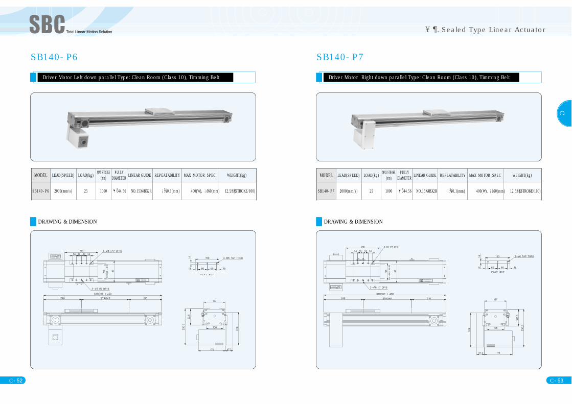
SB140-P6
Driver Motor Left down parallel Type: Clean Room (Class 10), Timming Belt
DRAWING & DIMENSION
FLAT NUT
MODEL LEAD(SPEED) LOAD(kg) MAX STROKE(mm)
PULLYDIAMETER LINEAR GUIDE REPEATABILITY MAX MOTOR SPEC WEIGHT(kg)
SB140-P6 2000(mm/s) 25 1000 44.56 NO.15X4BX2R 0.1(mm) 400(W), 60(mm) 12.5+(1.3XSTROKE/100)
SB140-P7
Driver Motor Right down parallel Type: Clean Room (Class 10), Timming Belt
DRAWING & DIMENSION
FLAT NUT
MODEL LEAD(SPEED) LOAD(kg) MAX STROKE(mm)
PULLYDIAMETER LINEAR GUIDE REPEATABILITY MAX MOTOR SPEC WEIGHT(kg)
SB140-P7 2000(mm/s) 25 1000 44.56 NO.15X4BX2R 0.1(mm) 400(W), 60(mm) 12.5+(1.3XSTROKE/100)

C
. Sealed Type Linear Actuator
C- 54 C- 55
SB180-D3
Driver Motor left direct connection Type: Clean Room(Class 10), Timming Belt
DRAWING & DIMENSION
FLAT NUT
MODEL LEAD(SPEED) LOAD(kg) MAX STROKE(mm)
PULLYDIAMETER LINEAR GUIDE REPEATABILITY MAX MOTOR SPEC WEIGHT(kg)
SB180-D3 2000(mm/s) 50 3000 44.56 NO.20X4BX2R 0.1(mm) 750(W), 80(mm)28.7+(2.17XSTROKE/100)
SB180-D4
Driver Motor Right direct connection Type, Clean Room (Class 10), Timming Belt
DRAWING & DIMENSION
FLAT NUT
MODEL LEAD(SPEED) LOAD(kg) MAX STROKE(mm)
PULLYDIAMETER LINEAR GUIDE REPEATABILITY MAX MOTOR SPEC WEIGHT(kg)
SB180-D4 2000(mm/s) 50 3000 44.56 NO.20X4BX2R 0.1(mm) 750(W), 80(mm)28.7+(2.17XSTROKE/100)
C
. Sealed Type Linear Actuator
C- 56 C- 57
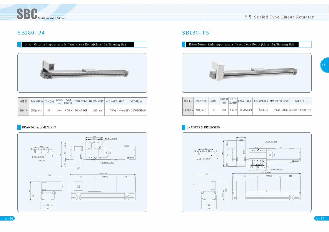
SB180-P4
Driver Motor Left upper parallel Type: Clean Room(Class 10), Timming Belt
DRAWING & DIMENSION
FLAT NUT
MODEL LEAD(SPEED) LOAD(kg) MAX STROKE(mm)
PULLYDIAMETER LINEAR GUIDE REPEATABILITY MAX MOTOR SPEC WEIGHT(kg)
SB180-P4 2000(mm/s) 50 3000 44.56 NO.20X4BX2R 0.1(mm) 750(W), 80(mm)28.7+(2.17XSTROKE/100)
SB180-P5
Driver Motor Right upper parallel Type: Clean Room (Class 10), Timming Belt
DRAWING & DIMENSION
MODEL LEAD(SPEED) LOAD(kg) MAX STROKE(mm)
PULLYDIAMETER LINEAR GUIDE REPEATABILITY MAX MOTOR SPEC WEIGHT(kg)
SB180-P5 2000(mm/s) 50 3000 44.56 NO.20X4BX2R 0.1(mm) 750(W), 80(mm)28.7+(2.17XSTROKE/100)
C
. Sealed Type Linear Actuator
C- 58 C- 59
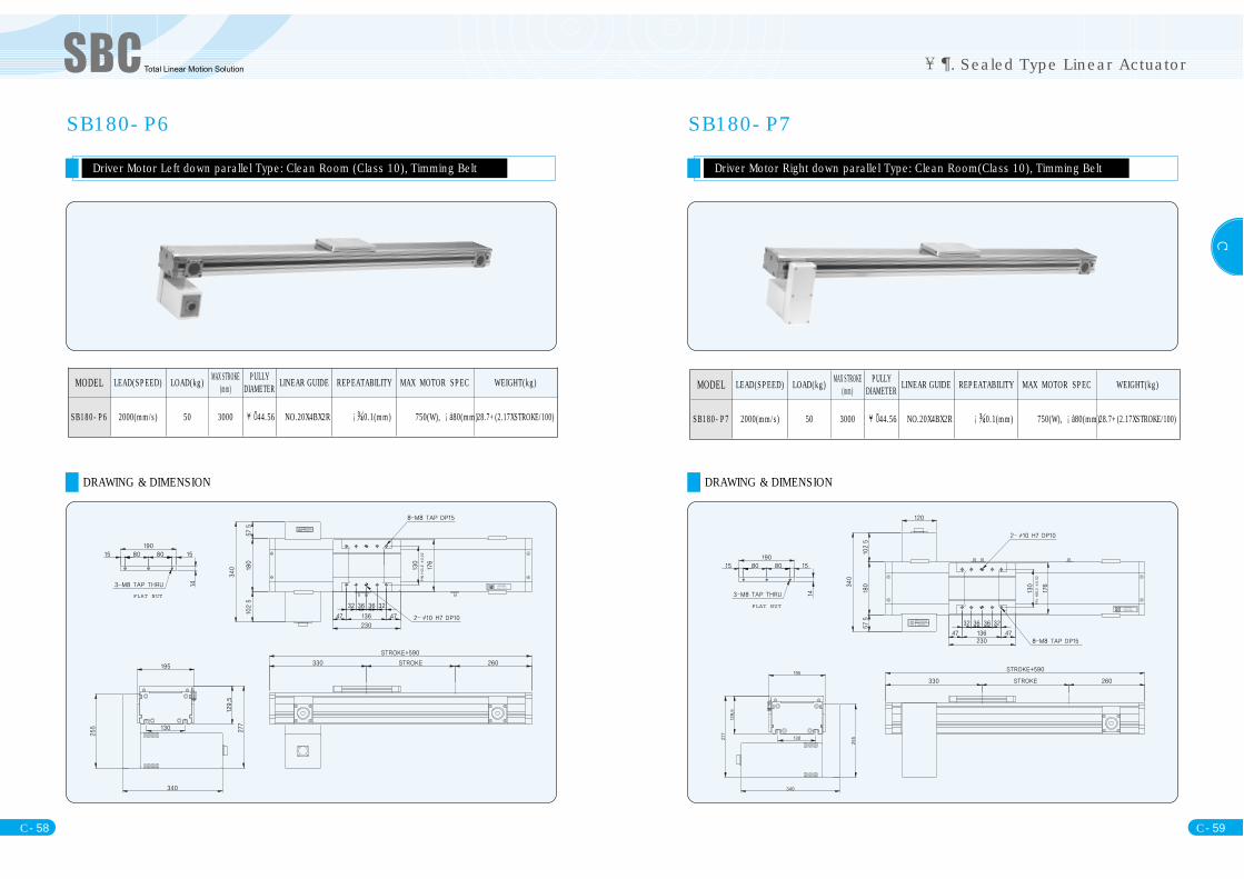
SB180-P6
Driver Motor Left down parallel Type: Clean Room (Class 10), Timming Belt
DRAWING & DIMENSION
FLAT NUT
MODEL LEAD(SPEED) LOAD(kg) MAX STROKE(mm)
PULLYDIAMETER LINEAR GUIDE REPEATABILITY MAX MOTOR SPEC WEIGHT(kg)
SB180-P6 2000(mm/s) 50 3000 44.56 NO.20X4BX2R 0.1(mm) 750(W), 80(mm)28.7+(2.17XSTROKE/100)
SB180-P7
Driver Motor Right down parallel Type: Clean Room(Class 10), Timming Belt
DRAWING & DIMENSION
FLAT NUT
MODEL LEAD(SPEED) LOAD(kg) MAX STROKE(mm)
PULLYDIAMETER LINEAR GUIDE REPEATABILITY MAX MOTOR SPEC WEIGHT(kg)
SB180-P7 2000(mm/s) 50 3000 44.56 NO.20X4BX2R 0.1(mm) 750(W), 80(mm)28.7+(2.17XSTROKE/100)

C. Linear Actuator Accessory
. Linear Actuator assembling example
C- 60 C- 61
. Linear Actuator Accessory
ROBO Cable
- Body connector ofSBC Linear Actuator is standard. If necessary, extended cable can be supplied.- Standard 1m, 3m, 5m, 7m, 19m
Motion cable - In case cable need lots of movementNon-motion cable - In case cable movement is few or cable is fixed,
Ordering) 3m Motion cable orderingOrdering example : RMC-3MA
When you place an order, please order it with motor model.Pin Map is supplied according to Motor model or Pin Ma iis indicated on the cable.
RMC : ROBO Cable Cable length Meter A:Motion typeB: Non-motion type
RMC M A
. Linear Actuator assembling example
SSW-XY1 SSW-XY2 SSW-XY3
SSW-XY4 SSW-XZ1 SSW-XZ2
SSW-XZ3 SSW-YZ4 SSW-XYZ1
XYZ2 XYZ3 XYZ4
C- 62
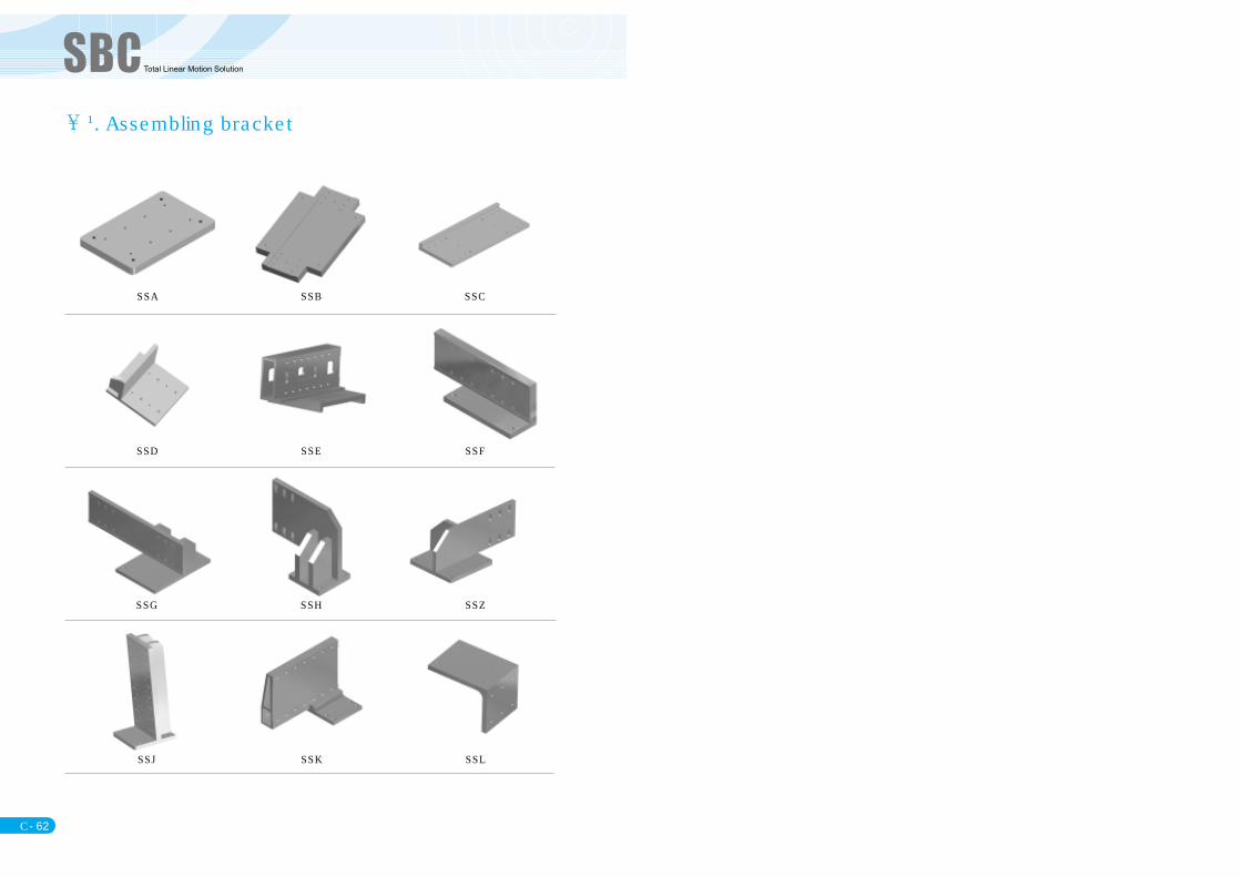
SSA SSB SSC
SSD SSE SSF
SSG SSH SSZ
SSJ SSK SSL
. Assembling bracket