sc re chap18- immiscible displ
DESCRIPTION
HW reservoir 18TRANSCRIPT

c ACTODD
Immiscible DisplacementImmiscible Displacement
Adrian C ToddAdrian C Todd
Heriot-Watt UniversityHeriot-Watt University
INSTITUTE OF PETROLEUM ENGINEERING
Heriot-Watt UniversityHeriot-Watt University
INSTITUTE OF PETROLEUM ENGINEERING

c ACTODD
Immiscible displacementImmiscible displacement Context: water displacing oil.Context: water displacing oil.
Water drive a very effective recovery mechanism.Water drive a very effective recovery mechanism.
Water injection a very common oilfield practise.Water injection a very common oilfield practise.
Modelling water drive is often carried out within Modelling water drive is often carried out within reservoir simulators.reservoir simulators.
Objective: to understand the mechanisms rather Objective: to understand the mechanisms rather than blindly using the ‘black box’.than blindly using the ‘black box’.
Useful texts; Dake & Chierici.Useful texts; Dake & Chierici.

c ACTODD
Reasons for Water InjectionReasons for Water Injection Main intervention method.Main intervention method.
High recovery & available fluids.High recovery & available fluids.
Historically considered as a secondary recovery process.Historically considered as a secondary recovery process.
Using water to sweep out previously unrecovered oil.Using water to sweep out previously unrecovered oil.
Todays perspective is keeping reservoir pressure above Todays perspective is keeping reservoir pressure above bubble point.bubble point.
Pressure maintenance. Voidage replacementPressure maintenance. Voidage replacement
Prevents solution gas drive.Prevents solution gas drive.

c ACTODD
Technical challenges of water InjectionTechnical challenges of water Injection
Water is produced.Water is produced.
Environmental. A disposal challenge of Environmental. A disposal challenge of contaminated water.contaminated water.
Reinjection of produced water.Reinjection of produced water.
Chemical incompatibility -scaleChemical incompatibility -scale
CorrosionCorrosion
BacteriaBacteria
c ACTODD
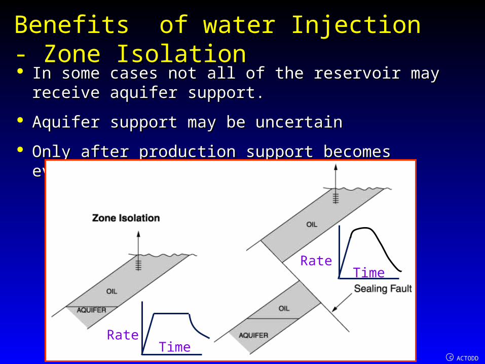
Benefits of water InjectionBenefits of water Injection- Zone Isolation- Zone Isolation In some cases not all of the reservoir may receive aquifer In some cases not all of the reservoir may receive aquifer
support.support.
Aquifer support may be uncertainAquifer support may be uncertain
Only after production support becomes evident.Only after production support becomes evident.
TimeRate
RateTime

c ACTODD
High PermeabilityHigh Permeability
kA dPq
dl
High injection / production ratesHigh injection / production rates
Wide well spacingWide well spacing
Rapid fluid movementRapid fluid movement
Accelerated developmentAccelerated development
Qi Qp

c ACTODD
Oil viscosityOil viscosity
Low oil viscosity leads to Low oil viscosity leads to good mobility ratio.good mobility ratio.
'rw w'ro o
k /Mobility Ratio, M
k /
Krw’Kro’
M < 1 gives piston like displacement
1-Sor
Sw
Swc
x
OilWaterKrw’
Kro’
Oil

c ACTODD
Undersaturated Undersaturated Reservoirs Reservoirs
Pressure surveys Pressure surveys can give an can give an excellent insight excellent insight into communication into communication in the reservoir.in the reservoir.
Enables layered Enables layered nature so important nature so important in waterflooding to in waterflooding to be defined.be defined.

c ACTODD
Overpressured ReservoirsOverpressured Reservoirs
Can let the pressure fall significantly Can let the pressure fall significantly to get a ‘feel’ of the reservoir.to get a ‘feel’ of the reservoir.
P
Time
5500psi
3500psi
4500psi
Pressure
De
pth
1000-2000psiN. Viking Graben-N.Sea

c ACTODD
Reservoir DepthReservoir Depth In offshore environments In offshore environments
facilities very costly.facilities very costly.
In waterflooding injection In waterflooding injection wells at the extremes of the wells at the extremes of the formation.formation.
Well slots have to be Well slots have to be capable of reaching these capable of reaching these limits.limits.
Horizontal wells now enable Horizontal wells now enable shallower accumulations to shallower accumulations to be reachedbe reached

c ACTODD
Facility DesignFacility Design
Issues:Issues:
Where to inject.Where to inject.
Ability to inject.Ability to inject.
When and how much water is produced.When and how much water is produced.
How to handle it.How to handle it.

c ACTODD
Thermal FracturingThermal Fracturing Experience over recent years has Experience over recent years has
shown that water injection injectivity shown that water injection injectivity has been better than expected.has been better than expected.
The cold water has cooled the The cold water has cooled the formation such that injection formation such that injection pressures have been able to pressures have been able to overcome fracture pressure, which overcome fracture pressure, which reduces when cooled.reduces when cooled.
Thermal fracturing.Thermal fracturing.
Provides a higher injection area Provides a higher injection area than for a radial injection geometry than for a radial injection geometry

c ACTODD
Water HandlingWater Handling Water handling- one of the Water handling- one of the
major technical challenges major technical challenges of the oil industry.of the oil industry.
Environmental pressures Environmental pressures increasing in relation to oil increasing in relation to oil emissions.emissions.
Reservoir engineers need Reservoir engineers need to predict water production to predict water production to enable design.to enable design.
When and how much.When and how much.

c ACTODD
Basic Waterdrive TheoryBasic Waterdrive Theory Method applicable to gas injection as well as water injection.Method applicable to gas injection as well as water injection.
Immiscible processImmiscible process
No mixing of the respective injection and displaced fluids.No mixing of the respective injection and displaced fluids.
Miscible processMiscible process where injected phases mix with displaced phase where injected phases mix with displaced phase by mass transfer of components.by mass transfer of components.
In our calculations we are combining properties, measurements and In our calculations we are combining properties, measurements and application over a huge range of physical scales.application over a huge range of physical scales.
This is the case in oil recovery predictions.This is the case in oil recovery predictions.
Important not to make ‘unrealsitic’ jumps in application of dataImportant not to make ‘unrealsitic’ jumps in application of data

c ACTODD
In water-oil displacement we are dealing with a process which takes place at In water-oil displacement we are dealing with a process which takes place at a range of scales.a range of scales.
Pore or microscopic scalePore or microscopic scale..
Isolation and movement of fluids is dependant on, IFT, wettability, viscosity, Isolation and movement of fluids is dependant on, IFT, wettability, viscosity, pore size and shape.pore size and shape.
Larger, macroscopic scaleLarger, macroscopic scale..
Behaviour at laboratory level scale, e.g. core plug scale. Permeability, relative Behaviour at laboratory level scale, e.g. core plug scale. Permeability, relative permeability and capillary pressure.permeability and capillary pressure.
Field Scale, or behavioural scaleField Scale, or behavioural scale..
Quantum leap of scale. Heterogeneous formations.Quantum leap of scale. Heterogeneous formations.
Vertical segregation over large thickness.Vertical segregation over large thickness.
Basic Waterdrive TheoryBasic Waterdrive Theory

c ACTODD
Levels of viewing Levels of viewing displacementdisplacement
Field scale
Electron microscope
scale
Core scale

c ACTODD
Water Oil Displacement at Microscopic and Water Oil Displacement at Microscopic and Macroscopic levelsMacroscopic levels
Trapped oil in swept area held by capillary Trapped oil in swept area held by capillary and IFT forces.and IFT forces.
Residual saturation SorResidual saturation Sor
10-40% of the pore space10-40% of the pore space

c ACTODD
Water Oil Water Oil Displacement at Displacement at Microscopic levelMicroscopic level

c ACTODD
Water Oil Displacement at Reservoir LevelWater Oil Displacement at Reservoir Level

c ACTODD
Factors that Dictate Flooding EfficiencyFactors that Dictate Flooding Efficiency
Mobility RatioMobility Ratio
HeterogeneityHeterogeneity
GravityGravity

c ACTODD
Relative PermeabilityRelative Permeability Darcy’s law for 100% single Darcy’s law for 100% single
phase saturation.phase saturation.
Relative permeability used to Relative permeability used to relate absolute permeability ( relate absolute permeability ( single phase ) to the effective single phase ) to the effective permeability when more than permeability when more than on phase present.on phase present.
Q k pu
A l
ewrw
kk
k

c ACTODD
Relative Relative PermeabilityPermeability Darcy’s law for linear Darcy’s law for linear
flow for two fluids in flow for two fluids in an inclined an inclined configuration.configuration.
ro oo o
o
rw ww w
w
kk A pq gSin
x
kk A pq gSin
x

c ACTODD
Relative Relative PermeabilityPermeability
End point relative End point relative permeabilities, krw’ & kro’.permeabilities, krw’ & kro’.
Limiting saturations of the Limiting saturations of the respective phasesrespective phases
Relative permeabilities from Relative permeabilities from 1D core floods.1D core floods.
Either viscous displacement or Either viscous displacement or steady state co-injection of steady state co-injection of fluids.fluids.
Unlikely to be representative Unlikely to be representative of reservoirof reservoir

c ACTODD
Relative PermeabilityRelative Permeability
SwcSorA
L
'rw w'ro o
k /Mobility Ratio, M
k /
Express volumes in the core plug as pore
volumes, PV.
PV AL
or wcMovable oil volume, MOV. PV 1 S S
End point rel. perm. values represent maximum velocity of the water flow compared to the maximum velocity of the oil.

c ACTODD
Fractional FlowFractional Flow For flow in core plug or a reservoir. Ratio of flow of water at any For flow in core plug or a reservoir. Ratio of flow of water at any
point is termed:point is termed:
fractional flowfractional flow..
ww
w o
qf
q q
o t wq q q
Subtracting Darcy equations for water and oil, P atmos.
c o wP p p
x x x
w o where
w o t o cw 6
rw ro ro
q P gSinq A
kk kk kk x 1.0133 10

c ACTODD
Fractional FlowFractional Flow
Values now inserted into fractional flow equation
ww
w o
qf
q q
ro c
6t o
wro w
rw o
kk A P gSin1
q x 1.0133 10f
k1
k
Dake simplified this to; wro w
rw o
1 Gf
k1
k
4 ro
t o
kk A gSinG 4.886 10
q
G = positive gravity number
qt/A=velocity term

c ACTODD
Impact of parameters on fractional flowImpact of parameters on fractional flow
Angle of dipAngle of dip
Water injected downdip gravity term is positive-Water injected downdip gravity term is positive-reduces fractional flow.reduces fractional flow.
If gas injection downdip gravity term positive If gas injection downdip gravity term positive increasing fractional flow of gas.increasing fractional flow of gas.
If dip angle zero, horizontal flow, gravity term is zeroIf dip angle zero, horizontal flow, gravity term is zero
4 ro
t o
kk A gSinG 4.886 10
q

c ACTODD
Impact of parameters on fractional flow- Impact of parameters on fractional flow- Capillary pressureCapillary pressure
Capillary pressure increases fractional flow of water
c c w
w
P P S
x S x
ro c6
t ow
ro w
rw o
kk A P gSin1
q x 1.0133 10f
k1
k

c ACTODD
Impact of parameters on fractional flow- Impact of parameters on fractional flow- velocityvelocity
For edge water drive velocity much higher than For edge water drive velocity much higher than bottom water drive- e.g. v=0.2ft/dbottom water drive- e.g. v=0.2ft/d
G=0.22G=0.22
For bottom water much lower velocity v= 0.004 ft/dFor bottom water much lower velocity v= 0.004 ft/d
G=10.29G=10.29
Leads to piston displacement for bottom water Leads to piston displacement for bottom water drive.drive.
Problem here however is well bore coningProblem here however is well bore coning
4 ro
t o
kk A gSinG 4.886 10
q

c ACTODD
Fractional FlowFractional Flow
If angle of dip and If angle of dip and capillary pressure capillary pressure effects ignored. effects ignored.
Fractional flow Fractional flow equation becomesequation becomes
ww ro
o rw
1f
k1
k

c ACTODD
Relationship between capillary pressure,relative Relationship between capillary pressure,relative permeability and fractional flowpermeability and fractional flow

c ACTODD
Relationship Relationship between capillary between capillary pressure, relative pressure, relative permeability and permeability and fractional flowfractional flow
At A the well only produces oil
At B,45%saturation both oil & water produced with water cut of 50%.
At C advancing water isolated irreducible oil saturation

c ACTODD
Displacement TheoriesDisplacement Theories Assumptions:Assumptions:
Displacement is incompressibleDisplacement is incompressible..
qqtt=q=qoo+q+qww=q=qii
qqtt=total flow rate in reservoir.=total flow rate in reservoir.
qqoo=oil flow rate in reservoir.=oil flow rate in reservoir.
qqww=water flow rate in reservoir.=water flow rate in reservoir.
qqii=water injection flow rate in reservoir.=water injection flow rate in reservoir.
Diffuse FlowDiffuse Flow
The saturations at any point are uniformly distributed The saturations at any point are uniformly distributed over the thickness.over the thickness.

c ACTODD
Diffuse FlowDiffuse Flow Enables a 1 dimensional simple analysis.Enables a 1 dimensional simple analysis.
A simple core flood this assumption not A simple core flood this assumption not unreasonable.unreasonable.
Can be encountered in a reservoir injection Can be encountered in a reservoir injection where rates are high and vertical equilibrium where rates are high and vertical equilibrium not able to be established.not able to be established.
For low injection rates where the thickness is For low injection rates where the thickness is small compared to transition zone.small compared to transition zone.

c ACTODD
Buckley-Leverett TheoryBuckley-Leverett Theory
Established in 1942 for displacement calculations.Established in 1942 for displacement calculations.
Theory for linear one dimensional displacement.Theory for linear one dimensional displacement.
Total flow rate is constant. (Incompressible ).Total flow rate is constant. (Incompressible ).
Theory determines the velocity of a plane of constant Theory determines the velocity of a plane of constant water saturation moving through a linear system.water saturation moving through a linear system.
e.g. a core.e.g. a core.
Well founded on principle of conservation of massWell founded on principle of conservation of mass
c ACTODD
Buckley-Leverett TheoryBuckley-Leverett Theory
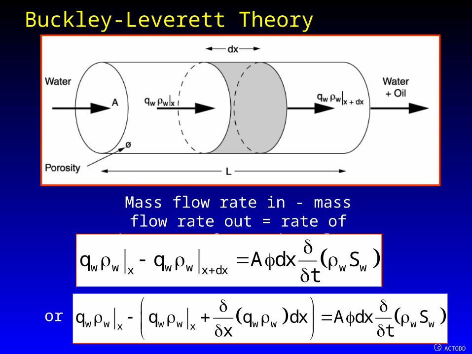
Mass flow rate in - mass flow rate out = rate of increase of mass in volume
w w w w w wx x dxq q A dx S
t
or w w w w w w w wx xq q q dx A dx S
x t

c ACTODD
Buckley-Leverett TheoryBuckley-Leverett Theory
w w w wq A Sx t
For incompressible flow , wconstant
w w
t x
q SA
x t
Differential of water saturation is
w ww t
x
S SdS dx dt
x t

c ACTODD
Buckley-Leverett TheoryBuckley-Leverett TheoryWe are examining the advancement of a particular saturation.
Sw is constant therefore dSw=0, therefore
w w
Swx
S S dx
t x dt
Alsow w w
t w t
q q S
x S t
Combining in w w
t x
q SA
x t
givesw
Swt
q xA
S t
For incompressible flow qt is constant.
Water flow rate is total flow times fractional flow, qw=qt x fw.
t wSw
Sw w Sw
q fdxv
dt A S
VSw is the velocity of the plane of saturation,Sw

c ACTODD
Buckley-Leverett TheoryBuckley-Leverett Theory
This is the Buckley-Leverett equation.This is the Buckley-Leverett equation.
Also called the Equation of Characteristics.Also called the Equation of Characteristics.
It indicates the velocity of a plane of saturation It indicates the velocity of a plane of saturation moving through the linear system.moving through the linear system.
It enables the calculation of Sw as a function of time It enables the calculation of Sw as a function of time and distance.and distance.
It indicates the dependance on the derivative of the It indicates the dependance on the derivative of the fractional flow curve.fractional flow curve.
t wSw
Sw w Sw
q fdxv
dt A S

c ACTODD
Equation of CharacteristicsEquation of Characteristics
Clierici has given a thorough analysis of the Clierici has given a thorough analysis of the displacement process for three fractional flow displacement process for three fractional flow curve types.curve types.
Important to understand the initial boundary Important to understand the initial boundary conditionsconditions
L
w wiS S for o<x L, t o w orS 1 S for x=0, t o
w wiS S for o<x L, t o w orS 1 S for x=0, t o

c ACTODD
Equation of CharacteristicsEquation of Characteristics
If the initial conditions at t=0 are applied to the general equation
t wSw
Sw w Sw
q fdxv
dt A S
and the equation is then integrated a general solution of the displacement process is obtained for the calculation of Sw in
terms of x and t.Velocity x time =distance.
t ww 0 wt
w Sw
q dfx S x S t
A dS
This equation describes a series of straight lines, the characteristics, with an initial ordinate value of 0 wx S
and slope oft w
w Sw
q df
A dS

c ACTODD
Viscous OilsViscous Oils Viscosity of displaced phase much greater Viscosity of displaced phase much greater
than injected water phase.than injected water phase.
Fractional flow curve has a concave Fractional flow curve has a concave downward slope.downward slope.
Its gradient fw’ increases from Sw=1-Sor. To a Its gradient fw’ increases from Sw=1-Sor. To a maximum at Sw=Swi+maximum at Sw=Swi+SwiSwi

c ACTODD
Viscous Oils
Cierici

c ACTODD
Velocity of Sw increases from its value at Sw=1-Sor to its maximum Velocity of Sw increases from its value at Sw=1-Sor to its maximum at Sw just greater than Swi.at Sw just greater than Swi.
Heavy oil produces water very early and steadily increases until too Heavy oil produces water very early and steadily increases until too high levels of water.high levels of water.
Viscous OilsViscous Oils
Cierici

c ACTODD
Very light oilsVery light oils
Low relative viscosity to injected water.Low relative viscosity to injected water.
Large gravitational effects.Large gravitational effects.
Low velocityLow velocity
Concave upward fractional flow curve.Concave upward fractional flow curve.
fw’ curve decreasing from value at Sw=1-Sor fw’ curve decreasing from value at Sw=1-Sor to a minimum at Sw just greater than Swi.to a minimum at Sw just greater than Swi.

c ACTODD
Very light oils
Cierici
upwards

c ACTODD
Fastest saturation 1-Sor quickly overtakes other saturations.Fastest saturation 1-Sor quickly overtakes other saturations.
Shock front developed.Shock front developed.
Until shock front arrives water free oil productionUntil shock front arrives water free oil production
Very light oilsVery light oils
Cierici

c ACTODD
Typical Medium Density OilsTypical Medium Density Oils Displacement velocities not unlike field Displacement velocities not unlike field
valuesvalues
S shaped fractional flow curveS shaped fractional flow curve
Two curvaturesTwo curvatures
Derivative curve, fw’. Slope Derivative curve, fw’. Slope increases from its starting value increases from its starting value Sw=1-Sor and then decreases.Sw=1-Sor and then decreases.
Cierici

c ACTODD
Typical Medium Density OilsTypical Medium Density Oils Development of the saturation would be a steady increase in Development of the saturation would be a steady increase in
the velocity of the increasing saturation.the velocity of the increasing saturation.
This would reach a maximum at Swf whereSwi<Swf<(1-Sor)This would reach a maximum at Swf whereSwi<Swf<(1-Sor)
Behind this velocities decrease with increasing Sw. Behind this velocities decrease with increasing Sw.
Cierici

c ACTODD
Typical Medium Density OilsTypical Medium Density Oils A shock front is developed at value of Swf.A shock front is developed at value of Swf.
The saturations greater than this moving at a lower velocity.The saturations greater than this moving at a lower velocity.
Behind this shock front a steady increase in the saturations Behind this shock front a steady increase in the saturations moving at decreasing velocitymoving at decreasing velocity
Cierici

c ACTODD
Water free oil is produced until breakthrough at Water free oil is produced until breakthrough at saturation saturation SSwfwf and fractional flow of and fractional flow of ffwbtwbt..
Saturation then climbs until irreducible oil saturation Saturation then climbs until irreducible oil saturation value, when only water is produced.value, when only water is produced.
Typical Medium Density OilsTypical Medium Density Oils
Cierici

c ACTODD
Velocity of shock frontVelocity of shock front Material balance across Material balance across
the shock front.the shock front.
R ahead L behind.R ahead L behind.
Velocity of front vf=dxf/dt
w,L w,R w,L w,R fq dt q dt A S S dx
Sincetw wq q f
w,L w,Rtf
f
w,L w,F
f fqdxv
dt A S S
Since t tq Au
w,L w,Rtff
w,L w,F
f fudxv
dt S S
Rankine-Hugoniot
condition for velocity of shock fronts

c ACTODD
Velocity of shock frontVelocity of shock front
Limiting conditionsLimiting conditions
w,L or w,R wi
w,L w,R
S 1 S S S
f 1 f 0
Therefore
w,L w,R
or wiw,L w,R
f f 1tan
1 S SS S

c ACTODD
From Buckley Leverett equation1 Sor
t wSw
1 Sor w 1 Sor
u fdxv
dt S
Combining equations
w,L w,Rt w t t t1 Sor
1 Sor w or wiw,L w,R1 Sor
f fu f u u udx 1v tan
dt S 1 S SS S
If we apply the Rankine-Hugonoit condition to the medium oil viscosity condition, the S shaped fw curve
w,L wf w,R wi
w,L w wf w,R
S S S S
f f S f 0
w,L w,Rt w t t wf twf
wf w wf wiw,L w,Rwf
f fu f u u f udxv tan
dt S S SS S

c ACTODD
Graphical ProcedureGraphical Procedure Examination of these equations provides a convenient Examination of these equations provides a convenient
procedure to determine conditions at the shock frontprocedure to determine conditions at the shock front
w wf
w wf wiwf
df ftan
dS S S
w wf
w wf wiwf
df ftan
dS S S
Tangent drawn to the fractional flow curve from Swi,0, meets the curve at
shock front conditions.
Time for breakthough to producer
wf wibt
f t w swf
S SL Lt
v u f

c ACTODD
Welge AnalysisWelge Analysis Welge provided a method to obtain average saturation Welge provided a method to obtain average saturation
behind shock front.behind shock front.
Useful for oil recovery calculations.Useful for oil recovery calculations.
Water injected at a rate of qw
Time for breakthrough, tbt wf wi
btf w w swf
S SL ALt
v q f

c ACTODD
Welge Welge AnalysisAnalysis
Before water arrives at producer, the volume of
oil produced is equivalent to volume of water injected, Wi=qw x t.
At breakthrough volume of oil produced, Np is also the difference between the initial oil volume, (AL(1-Swi). Less
that remaining in terms of the average water saturation, Sw, (AL(1-Swavg)
pbt w btN q t
pbt w wiN AL S S

c ACTODD
Welge Welge AnalysisAnalysis
wf wipbt w bt w wi
w swf
S SN q t AL AL S S
f
Therefore wf wiw wi
wf
S SS S
f
From a previous equation w wf
w wf wiwf
df ftan
dS S S
Therefore w wi
w
w Swf
1S S
dfdS

c ACTODD
Welge Welge AnalysisAnalysis
Combining equations gives
wf wi w wf wwf wbt wf
w wi w wi w Swf
S S S S df1 f 1 S S
S S S S dS
Rearranging gives wfwbt wf
w
w Swf
1 fS S
dfdS
w wf
w wbt wf wbt wiSwf
df 1 f 1
dS S S S S

c ACTODD
Welge Welge AnalysisAnalysis
This provides another graphical significance enabling the average saturation to be determined.
w wf
w wbt wf wbt wiSwf
df 1 f 1
dS S S S S
The line of the tangent at breakthrough also cuts the fw=1 line at
Sw=Sw avg

c ACTODD
Oil Recovery CalculationsOil Recovery Calculations Analysis so far is for displacement process for a small Analysis so far is for displacement process for a small
core plug of oil by watercore plug of oil by water
In recovery calculations useful to express volumes in In recovery calculations useful to express volumes in pore volumes, PVpore volumes, PV
SwcSorA
L
PV A L
c ACTODD
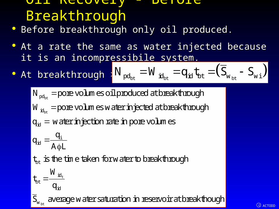
Oil Recovery - Before BreakthroughOil Recovery - Before Breakthrough Before breakthrough only oil produced.Before breakthrough only oil produced.
At a rate the same as water injected because it is an At a rate the same as water injected because it is an incompressibile system.incompressibile system.
At breakthrough >At breakthrough > bt bt btpd id id bt w wiN W q t S S
bt
bt
pd
id
id
iid
bt
idbt
N pore volumes oil produced at breakthrough
W pore volumes water injected at breakthrough
q water injection rate in pore volumes
A L
t is the time taken for water to breakthrough
Wt
t
bt
id
w
q
S average water saturation in reservoir at breakthough

c ACTODD
Oil Recovery - Before BreakthroughOil Recovery - Before Breakthrough At breakthrough when x=LAt breakthrough when x=L
In Buckley-Leverett eqn.In Buckley-Leverett eqn.
t bt w wiSw bt bt Sbt
Sw w wSw Sw
q t f fdx Wv t t x L
dt A S A S
iid
w
w Swbt
W 1W
LA dfdS
Oil recovery at breakthrough equal to inverse of the slope of breakthrough characteristic, the slope of line drawn from Swi to
tangent of fractional flow curve.

c ACTODD
Oil Recovery - Before BreakthroughOil Recovery - Before Breakthrough
t bt tpd id id bt w wibt
w
w Swbt
1N W q t S S
dfdS

c ACTODD
Oil Recovery - After BreakthroughOil Recovery - After Breakthrough After breakthrough the saturation at the exit of the After breakthrough the saturation at the exit of the
core increases until irreducible oil saturation reached.core increases until irreducible oil saturation reached.
From Welge equationw Swe
w we
w
w Swe
1 fS S
dfdS

c ACTODD
Oil Recovery - Oil Recovery - After BreakthroughAfter Breakthrough
In terms of pore volumes
w we w idSweS S 1 f W
Oil recovery
pd w wi we wi w idSweN S S S S 1 f W

c ACTODD
Oil Recovery - After BreakthroughOil Recovery - After BreakthroughThis equation pd w wi we wi w idSwe
N S S S S 1 f W
Also gives a useful construction to
determine average saturation
w Swew
w w weSwe
1 fdf
dS S S
w Swew
w w weSwe
1 fdf
dS S S
A line tangential to the FF curve at the exit water saturation intersects fw=1 at the S avg value.

c ACTODD
Oil Recovery Calculation procedureOil Recovery Calculation procedure 1. Generate a fractional flow vs. water saturation curve 1. Generate a fractional flow vs. water saturation curve
using appropriate rel.perm . data.using appropriate rel.perm . data.
2. Draw a tangent to the fractional flow curve from the 2. Draw a tangent to the fractional flow curve from the point Sw=Swi position at fw=0point Sw=Swi position at fw=0
(i) fw=fwbt, Sw=Swbt(i) fw=fwbt, Sw=Swbt
(ii)extrapolation of line to fw=1 gives average (ii)extrapolation of line to fw=1 gives average saturation value.saturation value.
(iii)(iii) t bt t
wpd id id bt w wibt
w Swbt
dfN W q t S S 1/
dS
(iii) Time for breakthrough is btidbt
id
Wt
q

c ACTODD
Oil Recovery Calculation procedureOil Recovery Calculation procedure After breakthrough.After breakthrough.
Select a saturation greater than breakthrough value and:Select a saturation greater than breakthrough value and:
(i) fw=fwe, Sw=Swe and extrapolation of tangential line to fw=1 (i) fw=fwe, Sw=Swe and extrapolation of tangential line to fw=1 gives average saturation value.gives average saturation value.
(ii) Oil recovery is (ii) Oil recovery is
pd w wi we wi w idSweN S S S S 1 f W
iid
w
w Swe
W 1W
LA dfdS
(iii) Time for breakthrough is
e
e
idbt
id
Wt
q
This step is repeated for increasing values of Swe up to Sw=1-Sor.

c ACTODD
Oil RecoveryOil Recovery
Up to breakthrough the recovery is linear as the oil recovered is equal to water injected.
After breakthrough recovery determined by fractional flow curve.

c ACTODD
Impact of ViscosityImpact of Viscosity Viscosity has a very significant impact on the fractional flow curve
A - high oil/water viscosity ratio.
Dense, viscous oilunstable displacement.
Would require many pore
voumes of water to displace oil
M>>1
Improving recovery by reducing viscosity.
Thermal recovery EOR.Effect on oil greater than
water

c ACTODD
Impact of ViscosityImpact of Viscosity Viscosity has a very significant impact on the fractional flow curve
B - medium viscosity ratio.
More stable favourable displacement.
Shock front developed
M around 1

c ACTODD
Impact of ViscosityImpact of Viscosity Viscosity has a very significant impact on the fractional flow curve
C - very low oil:water viscosity ratio.
Light oil
Fractional flow curvature opposite to case A
Very stable displacement.
Piston like
M < 1

c ACTODD
Impact of ViscosityImpact of Viscosity

c ACTODD
Shape of the Fractional Flow for Most Common Shape of the Fractional Flow for Most Common Flooding Condition (M<1)Flooding Condition (M<1)
At point of chord contact
pd w wcN S S (PV)
pd or wcN 1 S S =1 (MOV)
Piston like displacement

c ACTODD
Shape of the Very Worst Type of Flooding Shape of the Very Worst Type of Flooding Condition (M>>1)Condition (M>>1)
Concave downward shape:implies that all saturations can be seen to have independent mobility

c ACTODD
Application to reservoir systemsApplication to reservoir systemsAnalysis so far is for one dimensional situations where a uniform saturation distribution can be assumed over the flow cross section. Diffuse flow.
For example a core plug.
Reservoirs generally cannot be handled with such simplicity.
The reservoirs have thickness and vertical permeability, giving rise to segregated flow.
The reservoirs may not be homogeneous but made up of layers which may or may not be in communication

c ACTODD
Two dimensional behaviour segregated flowTwo dimensional behaviour segregated flow In diffuse flow uniform saturation distributed over thickness.In diffuse flow uniform saturation distributed over thickness.
Need to scale up to 2 dimensions to give more realistic Need to scale up to 2 dimensions to give more realistic perspective.perspective.
Segregated flowSegregated flow
Leads to saturation distribution over the thickness.Leads to saturation distribution over the thickness.
DietzDietz
A sharp interface is assumed between oil bearing and A sharp interface is assumed between oil bearing and flooded part of formationflooded part of formation

c ACTODD
Segregated flow-Segregated flow-DietzDietz
Oil + immobile connatewater
Water + immobile residual oil
Core plug 1 dimensional
h
Assumptions:Homogeneous formation
Strong gravity segregationZero capillary pressure

c ACTODD
Segregated flowSegregated flow
Vertical equilibrium assumed to exist.
-large density contrast between
displacing fluid and oil.
High vertical permeability
Low oil viscosityLow fluid velocity

c ACTODD
Comparison of forcesComparison of forces
A useful indicator of dominating forces is the relation of viscous to capillary forces
ovc
uN
Cos
and viscous to gravity forces
o
vgo w o
uN
k g
Nvc and Nvg are the capillary and gravity numbers
In vertical equilibrium both of these are low.

c ACTODD
Segregated flowSegregated flowIn flooded part of the reservoir only water is
flowing.kw=kk’rw
In the unflooded zone only oil is flowing.ko=kk’ro
Distinct interface between oil and water
No capillary transition zone.

c ACTODD
Displacement Calculations for Displacement Calculations for Segregated FlowSegregated Flow
Consider a point in the displacement
path.We have a sharp interface over the
formation thicknessAt any point x, hw
represents fractional thickness below water
oil interface
Average saturation over this formation
thickness h is:
w w or w wcS h 1 S 1 h S
Solving for hw gives:w wc
wor wc
S Sh
1 S S
Since Sor & Swc are constant hw proportional to
Savg

c ACTODD
Displacement Calculations for Displacement Calculations for Segregated FlowSegregated Flow
w
'rw w rwS
k h k
Average relative permeability Average relative permeability over the thickness, the over the thickness, the
thickness averaged relative thickness averaged relative permeabilitypermeability is for water; is for water;
w
rw w rw w rwSw 1 Sor Sw SwcSk h k 1 h k
'rw wc rw rw w ork 0 at S and k k at S 1 S
Therefore
w
'rw w rwS
k h k k’rw is the end point
relative permeability to water

c ACTODD
Displacement Calculations for Displacement Calculations for Segregated FlowSegregated Flow
Average relative permeability Average relative permeability over the thickness, the over the thickness, the
thickness averaged relative thickness averaged relative permeabilitypermeability is for oil; is for oil;
w
ro w ro w roSw 1 Sor Sw SwcSk h k 1 h k
'rw ro wc ro w ork k at S and k 0 at S 1 S
k’ro is the end point
relative permeability to oil
Therefore w
'ro w rwS
k 1 h k

c ACTODD
Displacement Calculations for Displacement Calculations for Segregated FlowSegregated Flow
If hww is now replaced in:
w wcw
or wc
S Sh
1 S S
w
'w wcrw rwS
or c
S Sk k
1 S S
we have
w
'w wcrw rwS
or wc
S Sk k
1 S S
and
w
'or wro roS
or wc
1 S Sk k
1 S S
Relative permeability linear functions of average water saturation

c ACTODD
Displacement Calculations for Segregated FlowDisplacement Calculations for Segregated Flow
Relative permeability linear functions of average water saturation
Diffuse flow curves
Linear thickness averaged relative permeability some times calledpseudo relative permeability

c ACTODD
Displacement Calculations for Segregated FlowDisplacement Calculations for Segregated Flow
ProcedureProcedure
Using core determined relative permeability curves Using core determined relative permeability curves generate linear thickness averaged relative permeability generate linear thickness averaged relative permeability lineslines
Only end point values required for thisOnly end point values required for this
Calculate fractional flow curve using the Calculate fractional flow curve using the pseudo( thickness) averaged relative permeabilities.pseudo( thickness) averaged relative permeabilities.
Apply one dimensional calculations to determine Apply one dimensional calculations to determine breakthrough and recovery.breakthrough and recovery.

c ACTODD
Reservoir HeterogeneityReservoir Heterogeneity Because of the depositional process reservoir formations are Because of the depositional process reservoir formations are
heterogeneous.heterogeneous.
This has considerable impact on displacement process.This has considerable impact on displacement process.
Two types of heterogeneityTwo types of heterogeneity
Vertical heterogeneityVertical heterogeneity
Horizontal heterogeneity.Horizontal heterogeneity.
The total recovery Np of the fluids in place N, is a combination The total recovery Np of the fluids in place N, is a combination of the recovery in the respective dimensionsof the recovery in the respective dimensions
pV A
NE E
N EA is the areal sweep efficiency,EV is
the vertical sweep efficiency
Formations swept by water leaves oil at irreducible saturation.Unswept oil at the original satuation

c ACTODD
Reservoir HeterogeneityReservoir Heterogeneity

c ACTODD
Vertical HeterogeneityVertical Heterogeneity The process of formation generates considerable variations in rock The process of formation generates considerable variations in rock
properties.properties.
Major impact on the permeability.Major impact on the permeability.
Permeability variation has considerable impact on water drive.Permeability variation has considerable impact on water drive.
Vital that this heterogeneity perspective is well characterised.Vital that this heterogeneity perspective is well characterised.
A layer in the formation of very high permeability can have a very A layer in the formation of very high permeability can have a very serious impact on the oil recovery process.serious impact on the oil recovery process.
Another aspect of importance is the connectivity between layersAnother aspect of importance is the connectivity between layers
Open hole pressure surveys very powerful after production has started Open hole pressure surveys very powerful after production has started in identifying layers in identifying layers

c ACTODD
Pressure Pressure profilesprofiles

c ACTODD
Examples of Examples of pressure pressure surveyssurveys

c ACTODD
Areal HeterogeneityAreal Heterogeneity
Areal heterogeneity also effects sweep Areal heterogeneity also effects sweep efficiencyefficiency
Other impacts from well spacing and Other impacts from well spacing and configuration.configuration.
More uncertainty in areal sweep than vertical.More uncertainty in areal sweep than vertical.
Dake has suggested vertical calculations are Dake has suggested vertical calculations are done in combination with production data to done in combination with production data to history match areal sweep efficiency.history match areal sweep efficiency.

c ACTODD
Vertical Sweep Displacement CalculationsVertical Sweep Displacement Calculations
Methods used for diffuse flow can be used for Methods used for diffuse flow can be used for layered systems.layered systems.
For layers with communication.For layers with communication.
Cross flowCross flow
and for layers with no communicationand for layers with no communication
No cross flowNo cross flow
The first step is to identify the layers and their The first step is to identify the layers and their individual characteristicsindividual characteristics

c ACTODD
Vertical Sweep Displacement CalculationsVertical Sweep Displacement Calculations
hi
Thickness
ki
Permeability
i
Porosity
Swci
Connate water saturation
Sori
Irreducible oil saturation
k’rwi
End point relative permeability water
End point relative permeability oil
k’roi
i th layer

c ACTODD
Vertical Sweep Displacement CalculationsVertical Sweep Displacement CalculationsConsider vertical pressure communication between layers decide if there is cross flow or no cross flow.
Decide flooding order of layers
Generate thickness average saturations and relative permeabilties.
As each layer floods out
J is the ordering of the flooding
layers
j j
n
n N
j j or j j wcj 1 j n 1
w N
j jj 1
h 1 S h S
Sh

c ACTODD
Vertical Sweep Displacement CalculationsVertical Sweep Displacement Calculations
j
nwn
n'
j j rwj 1
rw NS
j j1
h k k
kh k
and
j
nwn
N'
j j roj n 1
ro NS
j j1
h k k
kh k
These average saturations and thickness averaged relative
permeabilities are then used to generate fractional flow curve
The problem can now be solved using the I-D approach

c ACTODD
Vertical Sweep Displacement Calculations - Vertical Sweep Displacement Calculations - Ordering of the layersOrdering of the layers
The engineer has some control on the ordering of the layers
If there is very strong vertical equilibrium with strong segregation then the layers will flood out from the bottom layer.

c ACTODD
Vertical Sweep Displacement Calculations - Vertical Sweep Displacement Calculations - Ordering of the layers- No cross flowOrdering of the layers- No cross flow
When there is no communication between layers then the layers will flood out according to the velocity of displacement of each layer.
Velocity of each layer i, is given by
i
i i
'i rw
i
i or wc
k kv
1 S S
‘Stiles’ then flooded out the natural layers in order of decreasing velocity. A mobility ratio around 1 is assumed.

c ACTODD
Ordering of the layers- No cross flowOrdering of the layers- No cross flow
Natural order
Increasing velocity

c ACTODD
Ordering of the layers- No cross flowOrdering of the layers- No cross flow
Increasing velocity
Ordering of layers impacts on the pseudo relative permeabilities, which results in a subsequent fractional flow curve.When fractional flow curve generated breakthrough and recovery analysis as for 1-D case.

c ACTODD
Impact of Capillary Pressure in Homogeneous Impact of Capillary Pressure in Homogeneous systemssystems
So far neglected capillary pressure for diffuse flow where So far neglected capillary pressure for diffuse flow where saturation uniformly distributed over thickness.saturation uniformly distributed over thickness.
And segregated flow where we have an oil-water contact.And segregated flow where we have an oil-water contact.
If capillary pressure significant then the transition zone If capillary pressure significant then the transition zone cannot be ignored.cannot be ignored.
If reservoir thin relative to transition zone-diffuse flow If reservoir thin relative to transition zone-diffuse flow conditions.conditions.
If transition zone negligible displacement segregatedIf transition zone negligible displacement segregated

c ACTODD
Impact of Capillary Pressure in Homogeneous Impact of Capillary Pressure in Homogeneous systemssystems
If neither of these two extremes exist capillary If neither of these two extremes exist capillary pressure needs to be considered.pressure needs to be considered.
Dake gives a full account. Based on moving the Dake gives a full account. Based on moving the transition zone in stages and at each stage transition zone in stages and at each stage determining average saturations and average relative determining average saturations and average relative permeabilities. These form the basis of new fractional permeabilities. These form the basis of new fractional flow curve then treated as 1-D case.flow curve then treated as 1-D case.
Impact is between diffuse flow and segregated flow.Impact is between diffuse flow and segregated flow.

c ACTODD
Impact of Capillary Impact of Capillary Pressure in Pressure in Homogeneous systemsHomogeneous systems
Dake
Dake

c ACTODD
Impact of relative position of high permeability Impact of relative position of high permeability layerslayers Figures of pseudo rel. perms. below for cross flow cases of Figures of pseudo rel. perms. below for cross flow cases of
the impact of the high permeability layer being at the top as the impact of the high permeability layer being at the top as compared to the base.compared to the base.
An example from ‘Dake’ of a three layer system is illustrated.An example from ‘Dake’ of a three layer system is illustrated.
High perm at top High perm at base
Dake

c ACTODD
Impact of relative position of high permeability Impact of relative position of high permeability layerslayers Fractional flow curvesFractional flow curves
Very early breakthroughShock front developed
Dake

c ACTODD
Impact of Permeability Distribution on Impact of Permeability Distribution on WaterfloodingWaterflooding
Previous layered illustration demonstrated impact Previous layered illustration demonstrated impact of relative position of layers in a heterogeneous of relative position of layers in a heterogeneous system.system.
Absolute values of k not so significant more the Absolute values of k not so significant more the relative contrast in permeability.relative contrast in permeability.

c ACTODD
Impact of Permeability Distribution on Waterflooding - Impact of Permeability Distribution on Waterflooding - Unfavourable permeability distributionUnfavourable permeability distribution

c ACTODD
Impact of Permeability Distribution on Waterflooding - Impact of Permeability Distribution on Waterflooding - Favourable permeability distributionFavourable permeability distribution
Archer

c ACTODD
Impact of Impact of Permeability Permeability Distribution on Distribution on WaterfloodingWaterflooding
Dake

c ACTODD
Impact of Permeability Distribution on Impact of Permeability Distribution on WaterfloodingWaterflooding
Fractional flow curve determines quality of water Fractional flow curve determines quality of water flood.flood.
Demonstrated by saturation at breakthrough and Demonstrated by saturation at breakthrough and subsequent production.subsequent production.
Shape of FF curve influenced by various factors.Shape of FF curve influenced by various factors.
Relative viscositiesRelative viscosities
endpoint relative permeabilitiesendpoint relative permeabilities
permeability distributionpermeability distribution

c ACTODD
Impact of Permeability Distribution on Impact of Permeability Distribution on WaterfloodingWaterflooding
Impact of mobility ratio ( viscosity effect) and permeability Impact of mobility ratio ( viscosity effect) and permeability distribution illustrated belowdistribution illustrated below
Coarsening down Coarsening upward
Very early breakthrough
even with favourable M
Shock front even at high M
Piston like displacement
Dake

c ACTODD
Impact of Permeability Distribution on Impact of Permeability Distribution on WaterfloodingWaterflooding
Impact on water Impact on water production.production.
Early water Early water breakthrough at low breakthrough at low water cut requires a water cut requires a long time to displace long time to displace oil.oil.
Coarsening up with Coarsening up with favourable mobility favourable mobility ratio leads to delayed ratio leads to delayed breakthrough then breakthrough then rapid increaserapid increase

c ACTODD
Application to Field PerformanceApplication to Field Performance The displacement equations can be used to examine actual field The displacement equations can be used to examine actual field
waterflood performance of fields in production.waterflood performance of fields in production.
Then used to generate information to determine future waterflood Then used to generate information to determine future waterflood strategy.strategy.
Development of a reservoir fractional flow curve..Development of a reservoir fractional flow curve..
Production data provides;Production data provides;
Oil production, NpOil production, Np
Water injection, WiWater injection, Wi
Exit fractional flow, fwsExit fractional flow, fws

c ACTODD
Application to Field PerformanceApplication to Field Performance
Using recovery equation
pd w wi we wi w idSweN S S S S 1 f W
The unknown Swe can be obtained, enabling a fw vs. Sw curve to be generated
This curve is much smoother than a typical eratic water cut vs. production curve

c ACTODD
Application to Field PerformanceApplication to Field PerformanceTypical water cut curve
Dake
Difficult to analyse

c ACTODD
Reservoir Fractional Flow CurveReservoir Fractional Flow Curve
Extrapolated Sw avgIncreased Sw avg due to increased water injection
Core data Sor

c ACTODD
Reservoir Fractional FlowReservoir Fractional Flow
Core data Sor
Allowing water cut to increase to high value would yield increased
recovery.However it would take a considerable time.
Another option is to increase injection rate if
facilties can be upgraded
. This would reduce time
to achieve recovery increase.
The option for the operator to progress round the reservoir FF curve is an
interesting approach

c ACTODD
Immiscible displacement in gas drive systemsImmiscible displacement in gas drive systems Method as generated for water-oil displacement can be Method as generated for water-oil displacement can be
used for gas-oil displacement.used for gas-oil displacement.
Mobility ratio for gas is very unfavourable because of large Mobility ratio for gas is very unfavourable because of large viscosity differenceviscosity difference
Gas drive is very unstable.Gas drive is very unstable. ' 'rg ro
g o
k k 0.5 1M / / 20
0.25 1
Fractional flow curve is also very unfavourable g
g ro
o rg
1f
k1
k

c ACTODD
gg ro
o rg
1f
k1
k
Immiscible displacement in gas drive systemsImmiscible displacement in gas drive systemsFractional flow curve is also very unfavourable
The full laboratory rel. perm. curves are not used since only the end point values used as gravity dominates leading to
segregated flow.

c ACTODD
Immiscible displacement in gas drive systemsImmiscible displacement in gas drive systems
Recovery calculations same as for water-oil.Recovery calculations same as for water-oil.
Can use the Buckley-Leverett and associated Can use the Buckley-Leverett and associated Welge analysis.Welge analysis.
Recovery of oil in gas drive equation is :Recovery of oil in gas drive equation is :
pd ge ge idN S 1 f G
Gid is the pore volumes of gas injected.
Equal to reciprocal of the slope of the FF curve at the exit gas saturation.

c ACTODD
Immiscible displacement in gas drive systems -Immiscible displacement in gas drive systems -Gravity segregationGravity segregation This is the dominant This is the dominant
perspective in gas driveperspective in gas drive
In gas cap drive the In gas cap drive the velocities are very low velocities are very low giving stable interface.giving stable interface.
When gas is injected When gas is injected along bedding.along bedding.
Unfavourable mobility plus Unfavourable mobility plus large gravity impact.large gravity impact.
Tendency for gas override.Tendency for gas override.

c ACTODD
Immiscible displacement in gas drive systems -Immiscible displacement in gas drive systems -Predicting performancePredicting performance
Carried out same way as for water-oil.Carried out same way as for water-oil.
Thickness average relative permeabilities generatedThickness average relative permeabilities generated
Layers flooded from the Layers flooded from the toptop..
Fractional flow curve generated.Fractional flow curve generated.
Calculations reduced to 1-D formCalculations reduced to 1-D form
j j
n
n
j j or wcj 1
g N
j jj 1
h 1 S S
Sh
j
n
n'
j j rgj 1
rg N
j j1
h k k
kh k
j
n
N'
j j roj n 1
ro N
j j1
h k k
kh k

c ACTODD
Immiscible displacement in gas drive systems -Immiscible displacement in gas drive systems -Gravity ImpactGravity Impact
gro g
rg o
1 Gf
k1
k
G is a positive gravity number 3 ro
o
kk A sinG 2.743 10
v
v is average Darcy velocity q/A at the injection front.
Actual velocity is: '
or wc
qv
A 1 S S
Oil recovery 'g g id
pdwc
S 1 f GN
1 S
'g gS and f are the averaged saturations and fractional flows
on the fractional flow curve after breakthrough

c ACTODD
Immiscible displacement in gas drive systems -Immiscible displacement in gas drive systems -
Impact of HeterogeneityImpact of Heterogeneity
Whereas for water-oil coarsening down gives rise to early water Whereas for water-oil coarsening down gives rise to early water breakthrough for gas injection it improves the flood profile.breakthrough for gas injection it improves the flood profile.
Higher permeability in lower layers counteracts density difference Higher permeability in lower layers counteracts density difference perspectiveperspective
Other parametersOther parameters
Stability of front affected by: k,q,Stability of front affected by: k,q,oo and and
Also affected by injection rateAlso affected by injection rate
c ACTODD
Immiscible Immiscible displacement in displacement in gas drive gas drive systemssystems
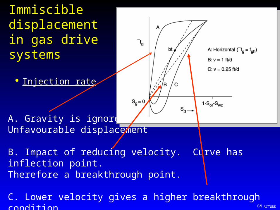
Injection rateInjection rate
A. Gravity is ignored.Unfavourable displacement
B. Impact of reducing velocity. Curve has inflection point.Therefore a breakthrough point.
C. Lower velocity gives a higher breakthrough condition

c ACTODD
Gas CyclingGas Cycling
Gas cycling is a possible Gas cycling is a possible option in the development option in the development of gas condensate of gas condensate reservoirs with a high reservoirs with a high condensate to gas ratiocondensate to gas ratio
In this process we have dry gas displacing wet gas.Very costly.Key issues are when does the dry gas arrive at the producer.?Although a miscible process can be analysed using the Buckley -Leverett approach.Usually modeled with a full compositional simulator

c ACTODD
Miscible Dry Gas-Wet gas DisplacementMiscible Dry Gas-Wet gas Displacement Core relative permeabilities are simple linear Core relative permeabilities are simple linear
functions since no residual gas saturations remains functions since no residual gas saturations remains after contact with dry gas.after contact with dry gas.
Mobilty ratio gives a reasonable displacement perspective
' 'rgd rgw
gd gw
k k 1 1M / / 1.5
0.02 0.03

c ACTODD
Miscible Dry Gas-Wet gas DisplacementMiscible Dry Gas-Wet gas Displacement Permeability variation has a Permeability variation has a
big impact.big impact.
High permeability at the top High permeability at the top favours early breakthrough.favours early breakthrough.
High permeability at the base High permeability at the base counterbalances slight counterbalances slight density impact.density impact.
High permeability layers High permeability layers within formation like water within formation like water flooding can give rise to early flooding can give rise to early breakthoughbreakthough